Workbook JXi Pool & Spa Heater
|
|
|
- Terence Godfrey Cook
- 5 years ago
- Views:
Transcription


1 Workbook JXi Pool & Spa Heater 1
2 2

3 Zodiac Pool Systems Inc Regional ext. Instructor: ext. Sales Representatives: ext. ext. ext. Service Manager: ext. ext. 3

4 Introduction The Jandy Pro Series JXi pool/spa heater is a blower assisted, internal combustion chamber, residential heater. Available Model Sizes: 200, 260 & 400K BTU's Model Numbers JXI200N, JXI200P, JXI260N, JXI260P, JXI330N, JXI330P, JXI400N, JXI400P Model BTU's JXI 400 N Gas Type N= Natural P = Propane General All gas fired appliances require correct installation to assure safe operation. The requirements for this pool heater include the following: Indoor vent adapter required for indoor installation. Must be vented with Type B Double wall for Category 1 venting or stainless steel vent pipe for Category 3. Water piping can be Schedule 40 PVC. Can be wired 120VAC or 240 VAC The JXi CAN be installed on combustable surfaces. Field Assembly - Properly size gas pipe to supply gas from the meter to the heater. - Gas shut-off valve (ball-cock) must be installed in-line outside of the heater jacket. - Suitable gas union must be installed to connect gas line to heater outside of the heater jacket. - Gas sediment trap (drip leg) in gas line between shut-off valve and heater. - Supplied power 120VAC or 240VAC (as local code requires) Proper Gas Pipe Sizing For LP gas, reduce pipe diameter by one size, but maintain a minimum 3/4 inch diameter. Heater Size Distance from Gas Meter 0-50 feet (0-15 m) feet (15-30 m) feet (30-60 m) in. mm in. mm in. mm / / / / / / / / / / /2 38 4
 70, or in Canada, the Canadian Electrical Code (CSA C22.1) unless local code requirements indicate otherwise.")
5 Installation Requirements (Field Assembly) Supplied power 120VAC or 240VAC Electrical wiring must be in accordance with the latest edition of the National Electric Code (NEC ), ANSI / National Fire Protection Association (NFPA ) 70, or in Canada, the Canadian Electrical Code (CSA C22.1) unless local code requirements indicate otherwise. The heater comes factory-wired intended for use with 240 Vot, 60 Hz AC field electrical supply. To use 120 Vot, 60 Hz AC requires changing the position of the voltage selector board on the power distribution board. This must be done by a certi ied electrician. Electrical Filter Filter Pump JXi Heater Power Distribution Board Conversion from 240 VAC to 120 VAC 10 1 FOR 240 VAC FOR 120 VAC
6 Installation Requirements PLUMBING Heater must be plumbed down steam of filter. Heater must be installed so that when the filter pump is off so to is the heater. All electrical equipment must be grounded and bonded. Plumbing Filter Filter Pump JXi Heater The JXi heater is Versa Plumb ready. The Versa Plumb System reduces hydraulic resistance by up to 50% versus other equipment sets in its class. The Versa Plumb System's increased hydraulic efficiency allows for up to a 1/2 HP smaller pump to achieve the same level of flow, resulting in greater energy savings. Faster installation with our pre-assembled plumbing kits, which enable quick and consistent equipment plumbing design to reduce installation costs. Innovatively designed system requires less plumbing pipe and fittings, while increasing hydraulic efficiency. 6
7 Installation Requirements Appropriate site location Clearances/ Combustable sufaces In both indoor installations (US) and outdoor shelter installations (Canada), the heater must be placed to provide clearances on all sides for maintenance and inspection, as well as maintain minimum distances from combustible surfaces. The following minimum clearances must be maintained from combustible surfaces during operation. Minimum Clearances for combustible surfaces TOP: EXHAUST SIDE: HEADER SIDE: DOOR PANELS: 6 inches (15 cm) 6 inches (15 cm) from surface of the exhaust vent 6 inches (15 cm) 6 inches (15 cm) Combustion and Ventilation requirements. Clearances Minimum vertical clearance = 36 inches Minimum clearance to at least one door panel = 18 inches Water Inlet Water Flow Model Min gpm (lpm) Max gpm (lpm) (114) 120 (454) (114) 120 (454) (114) 120 (454) (114) 120 (454) Water Outlet 7
8 Clearances to Openings Distance from heater to door, window or other opening to living structure. Dimension A 4 minimum A A Distance from heater to forced air inlet or other vented opening. Dimension B May be any distance if dimension C is 3 or more. Dimension B Must be at least 10 if dimension C is less than 3. C B Forced air inlet 8
 260 7\" (18cm) 330 8\" (20cm) 400 8\" (20cm) Table 2.")
9 Category l Venting 2 10 Vent Cap 1/4 inch minimum pitch per foot of horizontal pipe. 12 inches from ceiling Type B Double Wall Vent Pipe. Adequate air into room See next slide 12 inches from floor Heater Size Vent Size 200 6" (15cm) 260 7" (18cm) 330 8" (20cm) 400 8" (20cm) Table 2. Category I Vent Pipe Sizing Table Vertical or Horizontal Venting (Category III) When the installation requires horizontal venting in excess of what is allowed for Category I installations or calls for horizontal discharge, the JXi may be installed with a Category III venting system. See Table 3 for recommended vent size and run lengths without elbows. For each elbow installed, reduce the run length by 12 feet (3.7m) Heater Size Vent Size Special Gas Vent Length (vertical or horizontal) in feet (metres) 200 4" (10cm) TBD (m) 260 4" (10cm) 50ʹ (15m) 330 4" (10cm) TBD (m) 400 4" (10cm) 50ʹ (15m) Table 3. Category III Vent Pipe Sizing Table 9
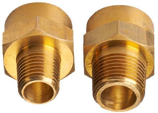
10 Vent Connection and Pipe Sizing Vent Pipe or Elbow Increaser Installation (Category I and Category III) 1. Remove the exhaust body. 2. Remove the exhaust rain shield.(figure 1) Exhaust Vent Rain Shield Figure 2. Remove Exhaust Body and Rain Shield 3. Category I: Install a draft hood connector and an increaser to meet the vent size requirements per Table 2. (See Figure 2.) Category III: Install vent connector or elbow to the flue colla according to the specific i stallation instructions from the vent connector or elbow component manufacturer. Figure 1 Figure 2. Remove Exhaust Body and Rain Shield 4. Wipe the socket of the vent body with rubbing alcohol using a clean cloth or paper towel, then. dry with a different clean cloth. 5. Connect the vent connector to the lue collar and fasten with three (3) sheet metal screws, as shown in Figure (3). Figure 2 Figure 3. Correct positioning of screws on vent collar 6. Apply high temperature silicone RTV at the connection to seal, as shown in Figure 4. TE: Use a minimum 600 F (315 C) temperature rated RTV. Figure 4. Seal Connection with RTV Figure 3 Figure 4 10

11 ON ON Connection to Controls JXi CONNECTED TO AQUALINK RS AT RS 485 LINE There are two ways of connecting a Jandy JXi heater to the AquaLink RS. One way is to connect at the Pool and Common terminals of the Power Interface Board. This type of connection is shown on the next page. The other way is to connect to the RS 485 line (red terminal bar) as shown here. When connected at the RS 485 line, the JXi and AquaLink RS become smart in that the control knows if the heater is malfunctioning. When connecting to the RS 485 line, the AquaLink RS firmware must be Rev N or newer. To establish communication between the LXi and AquaLink RS do either of the following: After making connection turn power off then on to the AquaLink RS. Hold the MENU button down for 5 seconds, then simply follow the screen prompts. Connection to Jandy Control - RS 485 J12 CONFIG J10 Air/Coil J 9 H2O GREEN YELLOW BLACK RED J17 RESET AUTO POOL MODE SPA MODE J16 SERVICE TIME OUT HEATER SOLAR SPA DRAIN SPA FILL J15 J 6 Power Interface Board (PIB) FIL- PMP AUX 1 AUX 2 AUX 3 AUX 4 AUX 5 AUX 6 AUX 7 INTAKE RETURN CLEANER SOLAR SLR-PMP E-HTR SPARE J 3 11
12 ON ON JXi Connected to Fireman s Switch J12 CONFIG J10 Air/Coil J 9 H2O J17 RESET POOL MODE J16 AUTO SPA MODE SPA POOL COMMON J15 J 6 Power Interface Board (PIB) SERVICE TIME OUT HEATER SOLAR SPA DRAIN SPA FILL FIL- PMP AUX 1 AUX 2 AUX 3 AUX 4 AUX 5 AUX 6 AUX 7 INTAKE RETURN CLEANER SOLAR SLR-PMP E-HTR SPARE J 3 JXi HEATER CONNECTION AT FIREMAN S SWITCH At the JXi Power Interface Board connect one end of two wires to terminals POOL and COMMON (J6). Connect the other end of these two wires to terminals 1 and 2 of the AquaLink RS Green terminal bar. Set pool thermostat to maximum (104 F). Set the JXi to recognize this type of connection by holding down MENU, POOL, and SPA buttons together for 7 to 10 seconds at the JXi s User Interface. Set REMOTE to T-Stat. Press POOL button to exit. HEATER IS OFF PRESS POOL OR SPA SELECT SERVICE SETUP REMO TE SELECT SERVICE SETUPREMOTE TSTAT * REMOTE * TSTAT ENABL * ED * 12


 Water Temp Diff F & C = +1 to +5 Hold down the POOL, MENU and SPA buttons for 5 to 10 seconds to enter the hidden")
13 DISPLAY BEZEL w/gasket & COVER P/N = R End User Menu, Universal Control, JXi LXi Hold down the Menu Button for 5 to 10 Seconds English Language Spanish French Temperature Scale Fahrenheit Celsius HEATER IS OFF PRESS POOL OR SPA Spa Timer Display Light Continuous 0:15 to 23:00 Hours On Off Hold down the MENU buttons for 5 to 10 seconds to enter the menu. 2 Minute Delay Installer/Technician Menu, Universal Control, LXi JXi Hold down the Pool, Menu, & Spa Button for 5 to 10 Seconds Maintain Temp Disable Enable Load Defaults No Yes F = + or - 4 Maintain Temp Delay 0:00 to 2:00 Hours Air Temp Cal C = + or - 4 Off F = + or - 4 HEATER IS OFF PRESS POOL OR SPA Remote Hi-Lo-Com Water Temp Cal C = + or - 2 Remote T-Stat Freeze Protect Off On (34º - 42º) Water Temp Diff F & C = +1 to +5 Hold down the POOL, MENU and SPA buttons for 5 to 10 seconds to enter the hidden menu. Disable Statistics Gas Valve on time (# of hours). Cycles (# of times heater fires). Louver Enable Last Fault * * * * 13

 R0589700 Heat Exchanger R0589402-05 As with all pool heaters")


14 Components - Water Flow Bypass Kit with Shaft, C-Clip and Poppet R Heat Exchanger Model 200 = 3 tubes Model 260 = 4 tubes Model 330 = 5 tubes Model 400 = 6 tubes Thermal Regulator Valve (TRV) R Heat Exchanger R As with all pool heaters water velocity and flow through the heat exchanger are controlled by an automatic bypass. The automatic bypass consists of a disk and spring and is located between the Inlet/Outlet header. A thermal regulator valve is also incorporated into this heater in the Inlet/Outlet header. Its purpose is to hold water in the exchanger during initial heat up to reduce the amount of condensate created at the heat exchanger. 14


15 Components - Electrical Release Button Ignition Control Power Interface Board Power Distribution Board Raceway Release Button Press to release 15

16 Power Distribution Circuit Board P/N = R To covert from 240 VAC to 120 VAC wiring, snip the wire tie holding the conversion board in place. Remove the conversion board, flip it over and reinsert FOR 240 VAC FOR 120 VAC 1 10 Power Interface Board (PIB) R

17 Ignition Control R Pre-Purge: 15 Sec. Ignition: 7 Sec. Interpurge: 15 Sec. Heat-Up: 40 Sec. Input : 24 VAC 50/60 Hz 300 ma Valve: 24 VAC, 2.0 A max. Inducer: 120/240 VAC, 3.0 A, ¼ HP Ignitor: 120 VAC, 5.0 A max. 50/60 Hz FENWAL Pre-Purge: 15 Sec. Ignition: 7 Sec. Interpurge: 15 Sec. Heat-Up 40 Sec. Input : 24 VAC 50/60 Hz 300 ma Valve: 24 VAC, 2.0 A max. Inducer: 120/240 VAC, 3.0 A, ¼ HP Ignitor: 120 VAC, 5.0 A max. 50/60 Hz GND VAL W PS IGN/FS To Gas Valve From Thermostat From Air Pressure Switch FC L2 Blower ON Pre-Purge 15 seconds 24 VAC F2 F1 L1 IGN/ 120 Hot Surface Igniter 40 seconds Heat Up To HSI out of phase with 120 VAC 17


 of the")


18 Transformer P/N = R This transformer is a center tap primary. When connected to the Power Distribution Board, this transformer provides 120 VAC to terminals L1 and L2 of the Ignition Control, whether the incoming power is 120 or 240 VAC. The secondary (24 VAC) of the transformer provides power to the Power Interface Board and the Ignition Control. In-Line Fuse - 2 amp P/N = R Fuse and Harness P/N = R Water Temperature Sensor R K Ohms thermistor Water Pressure Switch R


19 High Limit Temperature Sensors Kit R High Limit 150 F High Limit 135 F High Limit 150 F High Limit 135 F 19


20 Fuel Components Air Blower Air Pressure Switch Air Orifice Union Gas Orifice is located here Gas Valve 20


21 Blower Assembly R BLOWER INTAKE ORIFACE KIT BTU NATURAL LP 200 R R R R R R R R FUEL ORIFACE KIT BTU NATURAL LP 200 R R R R R R R R


 R0457500")
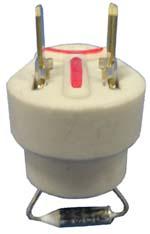
22 Air Pressure Switch R Gas Valve R Hot Surface Igniter (HSI) R Range 50 to 500 Ohms 22


23 Burner R Exhaust Temperature Switch R
 240 or 120 VAC between Black (C) wire and Red (B) wire on Power STEP 2- Check Transformer 24 VAC between Red (2) wire and Yellow (1) wire on Transformer?")
24 JXi Troubleshooting Guide TE: If Blower is on Go to Step 13 STEP 1- Check Power at Dist. Brd. (make certain filter pump motor is on) 240 or 120 VAC between Black (C) wire and Red (B) wire on Power STEP 2- Check Transformer 24 VAC between Red (2) wire and Yellow (1) wire on Transformer? STEP 3- Check Fuse 24 VAC between Red (3) wire on PIB and Yellow (1) wire on Transformer? STEP 4- Check power to Water Press. Sw. 24 VAC between Purple (4) wire on PIB and Yellow (1) wire on Transformer? STEP 5- Check Water Pressure Switch 24 VAC between Gray (5) wire on PIB and Yellow (1) wire on Transformer? STEP 6- Check power to Fusible Link 24 VAC between Orange (6) wire on PIB and Yellow (1) wire on Transformer? STEP 7- Check Fusible Link 24 VAC between Blue (7) wire on PIB and Yellow (1) wire on Transformer? Make certain filter pump is on. Correct wiring If wired 240 VAC check voltage between Black (E) wire and Blue (F) wire. If wired 120 VAC check voltage between Black (E) and White (D) wires. If the correct voltage is present, replace Transformer, if not check Conversion Board position Locate and correct short circuit, replace Fuse. Recheck at Red (3) wire, if voltage is 24 VAC replace PIB. Back Pressure Test, if pressure is higher than 2 PSI, replace Water Pressure Switch, if less clean filter, baskets or repair pressure problem Recheck voltage at Gray (5) wire, if voltage is 24 VAC replace PIB. Check Vent Limit and replace failed part if necessary. STEP 8- Check Power to High Limits 24 VAC between Black (8) wire on PIB and Yellow (1) wire on Transformer? STEP 9- Check High Limits 24 VAC between Black (9) wire on PIB and Yellow (1) wire on Transformer? STEP 10- Check Power to Ignition Control 24 VAC between Black/Yellow(10) wire on PIB and Yellow (1) wire on Transformer? STEP 11- Check Power at Ignition Control 24 VAC between Black/Yellow (11) at W terminal of Ignition Control and Yellow of Transformer? STEP 12- Check Blower Is Blower ON? Correct incoming power problem. STEP 13- Check Air Pressure Switch Recheck power at Blue (7) wire. If 24 VAC at Blue but not Black, replace PIB. Replace both High Limits. Do a Temp. Rise Test. Recheck power at Black (9) wire. If 24 VACat Black, but not Black/Yellow(10), replace PIB. Correct problem with Black/Yellow wire or its connectors. Check voltage between F2 terminal of Ignition Control and ground (A0. Is voltage 105 VAC or higher? Check voltage between F1 terminal of Ignition Control and ground (A). Is voltage 105 VAC or higher? If no, replace Ignition Control, if yes check voltage between Black (L) to Blower PDB and white wire. Wired 120, voltage range is 105 to 130, when wired 240 range is 210 to 250. If voltage is correct replace Blower. If not check PDB and wires.
25 Blower is ON Start on Step 13 STEP 13- Check Air Pressure Switch 24 VAC between Orange () wire at the Air Pressure Switch and Yellow (1) wire on Transformer? STEP 14- Check Power to PSW 24 VAC between Orange (12) wire at the Ignition Control and Yellow (1) wire on Transformer? STEP 15- Check Hot Surface Igniter After Blower comes on wait at least 15 seconds (pre-purge). Is Igniter glowing? STEP 16- Check for Ignition After the HIS begins to glow, wait approximately 40 seconds. Did the burners ignite? JXi Troubleshooting Guide Make certain Blower s on and combustion chamber is sealed. Check air tubes for kinks or holes. Make certain front air tube is connected to the positive (+) side and back/lower air tube is connected to negative (-) side of the Air Pressure Switch. If all are OK replace the Air Pressure Switch. Check wire connections. Replace Orange wire. Check voltage between K and J of the Ignition Control. If 105 to 130 VAC, check wires and connectors to the Igniter, if OK, replace Igniter. If voltage is less than 105 VAC check incoming voltage between L1 and L2, if voltage is 105 to 130 VAC replace Ignition Control. Check voltage on Brown (13) wire at terminal VAL of the Ignition Control. Is there 24 VAC at VAL? Replace Ignition Control. Check supply gas pressure. If OK, replace Gas Valve. STEP 17- Check Burners operation Do Burners stay on beyond 7 seconds? Step 18 Verify heating Heater is operating properly. Heater is not recognizing the flame (flame rectification). Any of the following can prevent flame rectification: Low gas pressure. Poorly connected or missing ground wire. Corroded or dirty Flame Sense Rod. Ignition Control not sending flame sense signal. Or there is insufficient current when the gas valve is powered. Current loss can be caused by any of the following: Excessive corrosion on wire terminals. Frayed or over heated wires. Pitting contact points, usually at the Water Pressure Switch or High Limits. To determine whether the problem is lack or rectification or loss or current, check voltage at the Black/Yellow(11) wire at Ignition Control. Keep the meter probe at this location and watch the reading. If, after the gas valve receives power, the voltage slowly drops until the gas valve shuts off, then returns to normal, the problem is due to loss of current. Note: If the Blower runs continuously, unplug F1/F2 connector from the Ignition Control, if the Blower goes off replace the Ignition Control. Of the Blower stays on, check for shorted wires between the Ignition Control and PDB or from the PDB and the Blower. Service Codes DISPLAY FUALT CAUSE REMEDY Fault- Pump 1. Pump is not running 1. This is a normal display when the control is in Maintain Temp mode. SERVICE REQUIRED. Flow Rates (gpm) BTUs MIN MAX FLOW FAULT HIGH LIMIT 1. Pump is not running 2. Low pump pressure. 3. Pressure switch fault 1. Water Temperature in heater exceeds the Internal limit. 2. Limit switch fault. 1. Check breakers and power source, recheck wiring, set time clock and current time. 2. Clean filter, clear blockages, check position of all valves in plumbing system 3. Adjust or replace pressure switch. Refer to qualified service personnel. 1. Verify function of high limit switches. Perform temperature rise test. Identify and correct cause of overheating. 2. Identify loose connections or replace switches. Refer to qualified Service Personnel GAS PRESSURE Inches of Water Column Natural LP Max Inlet Min Inlet 4 4 Gas Offset FAULT- FUSELINK/FIEL D FAULT- CHECK IGN CONTROL Fault- Shorted H2O Sensor Or Open Water Sensor 1. Vent Limit fault. 1. Broken, split, pinched or disconnected fan/switch tubing. 2. Fan not operating. 3. Fan running slow or premature fan failure. 4. Air flow restricted at intake or discharge. 5. Oscillating pump pressure. 6. Low gas supply pressure. 7. No flame at burners. 1. aulty wiring or connection. 2. Failed sensor. 1. Identify loose connections or replace Vent Limit. Refer to qualified Service Personnel. 1. Check tubing and replace if necessary. 2. Correct fault or replace fan. Refer to qualified service personnel. 3. Verify proper wiring for 120 or 240 VAC. Refer to qualified service personnel. 4. Check for proper clearances around heater and for adequate room ventilation if enclosed. Inspect for blockages or restriction at discharge of flue. Refer to qualified service personnel. 5. Clean filter or identify and repair cause of pump oscillation. 6. Identify and correct loose wiring connections, or problems with igniter, flame sensor, gas valve, or ignition control. Refer to qualified service personnel. 1. Inspect sensor wiring. Ensure sensor is connected into Power Interface Board. 2. Replace temperature sensor. Refer to qualified service personnel.
26
Instructor: Sales person: Phone: Sales person: Phone: Sales person: Phone: Sales person: Phone: Service Manager: Phone: Service Manager: Phone:
 LRZE HEATER Zodiac Pool Systems, Inc. 1-800-822-7933 Regional Extension www.zodiacpoolsystems.com Zodiac Academy zodiac.academy@zodiac.com www.zodiacacademy.com Instructor: Email: Sales person: Phone:
Internet Version for Reference Only INDUCED DRAFT COMMERCIAL WATER HEATERS SUPPLEMENT INSTRUCTIONS TO PART #
 INDUCED DRAFT COMMERCIAL WATER HEATERS SUPPLEMENT INSTRUCTIONS TO PART #238-39387-00 THIS INSTRUCTION SUPPLEMENT IS ONLY INTENDED TO GIVE INSTALLATION INSTRUCTIONS AND INFORMATION RELATED TO THE INDUCED
Jandy Pro Series JXi Gas-Fired Pool and Spa Heater Models 200, 260, 400
 INSTALLATION AND OPERATION MANUAL Jandy Pro Series JXi Gas-Fired Pool and Spa Heater Models 200, 260, 400 If these instructions are not followed exactly, a fire or explosion may result, causing property
Jandy Pro Series JXi Gas-Fired Pool and Spa Heater Models 200, 260, 400
 INSTALLATION AND OPERATION MANUAL Jandy Pro Series JXi Gas-Fired Pool and Spa Heater Models 200, 260, 400 WARNING IF THESE INSTRUCTIONS ARE NOT FOLLOWED EXACTLY, A FIRE OR EXPLOSION MAY RESULT, CAUSING
50M Integrated Single or Two-Stage HSI Integrated Furnace Control Kit INSTALLATION INSTRUCTIONS
 50M56-743 Integrated Single or Two-Stage HSI Integrated Furnace Control Kit INSTALLATION INSTRUCTIONS FAILURE TO READ AND FOLLOW ALL INSTRUCTIONS CAREFULLY BEFORE INSTALLING OR OPERATING THIS CONTROL COULD
M3RL Series TECHNICAL SPECIFICATIONS. FEATURES and BENEFITS. High Efficiency / Direct Vent Condensing Downflow Gas Furnace
 TECHNICAL SPECIFICATIONS M3RL Series High Efficiency / Direct Vent Condensing Downflow Gas Furnace Induced Draft - 90+ AFUE Input 60,000 & 80,000 Btuh The high efficiency downflow gas furnace is especially
TECHNICAL SPECIFICATIONS
 TM TECHNICAL SPECIFICATIONS Model PGF1TE 2 Stage Series Upflow/Horizontal M1010 Product Line High Efficiency / 95.1 AFUE Direct Vent or Non Direct Vent Condensing Furnace 10 YEAR WARRANTY WORRY-FREE PERFORMANCE
WARNING WARNING TROUBLESHOOTING GUIDE INTEGRATED FURNACE CONTROL MODULE
 TROUBLESHOOTING INTEGRATED FURNACE Failure to read and follow all instructions carefully before installing or operating this control, could cause personal injury and/ or property damage. 50A55 INTEGRATED
For More Information Click Here or Call General Supply M7RL Series TECHNICAL SPECIFICATIONS. FEATURES and BENEFITS
 TECHNICAL SPECIFICATIONS M7RL Series High Efficiency / Direct Vent Condensing Downflow Gas Furnace Induced Draft - 95%+ AFUE Input 45,000 thru 7,000 Btuh The high efficiency downflow gas furnace is especially
KG6TE Series. High Efficiency / Direct Vent or Non Direct Vent 2-Stage Condensing Gas Furnace with Variable Speed Blower TECHNICAL SPECIFICATIONS
 TECHNICAL SPECIFICATIONS KG6TE Series High Efficiency / Direct Vent or Non Direct Vent 2-Stage Condensing Gas with Variable Speed Blower 95.1 Upflow/Horizontal The high effi ciency 2-Stage gas furnace
RG7D 1-Stage Heat Series
 TECHNICAL SPECIFICATIONS RG7D 1-Stage Heat Series High Efficiency / Direct Vent Condensing Downflow Gas Furnace Induced Draft - 9%+ AFUE Input 4,000 thru 7,000 Btuh The high efficiency downflow gas furnace
Zodiac JXi Gas-Fired Pool and Spa Heater Models 200, 370
 INSTALLATION AND OPERATION MANUAL Zodiac JXi Gas-Fired Pool and Spa Heater Models 200, 370 IF THESE INSTRUCTIONS ARE NOT FOLLOWED EXACTLY, A FIRE OR EXPLOSION MAY RESULT, CAUSING PROPERTY DAMAGE, PERSONAL
FINNED WATER-TUBE POOL HEATERS
 HI DELTA, TYPE P - MODELS 992C-2342C SUGGESTED SPECIFICATIONS Catalog No.: 6000.611 Effective: 10-31-16 Replaces: NEW FINNED WATER-TUBE POOL HEATERS - GENERAL 1.1 SUMMARY A. Section includes gas-fired,
50M56U-843 INSTALLER MUST READ DESCRIPTION PRECAUTIONS WARNING CAUTION
 50M56U-843 Universal Single Stage HSI Integrated Furnace Control Kit INSTALLATION INSTRUCTIONS INSTALLER MUST READ PAGE 3 CONTAINS WIRING HARNESS AND BLOWER CONNECTION INSTRUCTIONS FOR ALL APPLICATIONS
TECHNICAL GUIDE MODELS: P*DH GAS-FIRED CONDENSING / HIGH EFFICIENCY DOWNFLOW / HORIZONTAL FURNACES 91 AFUE DESCRIPTION WARRANTY FEATURES
 036-1354-001 Rev. D (110) Heating TECHNICAL GUIDE MODELS: P*DH GAS-FIRED CONDENSING / HIGH EFFICIENCY DOWNFLOW / HORIZONTAL FURNACES 91 AFUE NATURAL GAS 37-111 MBH OUTPUT Air Conditioning EFFICIENCY RATING
Electronic Pellet Burner Controller NPBC-V3M
 Electronic Pellet Burner Controller NPBC-V3M SOFTWARE VERSION 3.3a/3.2 page of 27 CHANGES IN THE USER MANUAL OR IN THE CONTROLLER'S SOFTWARE Version of the user manual Changes Page 2.2. The software version
KG6RC Series TECHNICAL SPECIFICATIONS FEATURES AND BENEFITS
 TECHNICAL SPECIFICATIONS KG6RC Series High Efficiency / Direct Vent or Non Direct Vent Condensing Upflow/ Horizontal Gas Furnace Induced Draft - 92+ AFUE Input 40,000-120,000 Btuh The high effi ciency
Aqua Balance. AquaBalance TM CONTROL MODULE QUICK START GUIDE LEGEND
 Aqua Balance AquaBalance TM CONTROL MODULE QUICK START GUIDE 10 1 Domestic Hot Water temperature setpoint decreasing button 2 Domestic Hot Water temperature setpoint increasing button 3 Central Heating
GPC PASTA PRO INSTALLATION & USER OPERATION MANUAL
 GPC-14/18/20 GPC PASTA PRO INSTALLATION & USER OPERATION MANUAL GPC-18 shown with optional rinse station. NOTICE! After installation of your equipment, immediately contact your local gas supplier to obtain
Initial Troubleshooting
 Initial Troubleshooting nly qualified, trained service technicians with appropriate test equipment should service the heater. emember that all parts of the system affect heater operation. Before starting
OWNER S MANUAL. Vintage Signature Series models: AC750, AC1050, AC1100, AC1250, AC1500, AC1750. Proudly Made in the USA.
 OWNER S MANUAL Vintage Signature Series models: AC750, AC1050, AC1100, AC1250, AC1500, AC1750 Proudly Made in the USA support@aquacomfort.com 888-475-7443 Manufacturing High Quality, High Efficiency Heat
LATTNER BOILER COMPANY 9.5 HP Low-NOx Installation and Start-Up Checklist for Dry Cleaners
 1 1. General Installation Information (to be completed by technician) Date installed: Location (city & state): Cleaner s name: National Board number (boiler): Installed by (company): Installed by (technician):
OWNER S MANUAL. Models: AC110, AC125, AC150 made from 2003 through Proudly Made in the USA
 OWNER S MANUAL Models: AC110, AC125, AC150 made from 2003 through 2010 Proudly Made in the USA support@aquacomfort.com www.aquacomfort.com/service-and-support/ (888) 475-7443 Manufacturing High Quality,
FINNED WATER-TUBE POOL HEATERS
 HI DELTA, TYPE P - MODELS 502C-902C SUGGESTED SPECIFICATIONS Catalog No.: 6000.601A Effective: 07-12-18 Replaces: 10-31-16 FINNED WATER-TUBE POOL HEATERS - GENERAL 1.1 SUMMARY A. Section includes gas-fired,
WATER-TUBE POOL HEATERS
 XTHERM, TYPE P - MODELS 1005A-2005A SUGGESTED SPECIFICATIONS Catalog No.: 6000.63B Effective: 3-01-15 Replaces: 9-01-09 WATER-TUBE POOL HEATERS PART 1 - GENERAL 1.1 SUMMARY A. Section includes condensing,
G6RC Series TECHNICAL SPECIFICATIONS
 TECHNICAL SPECIFICATIONS G6RC Series High Efficiency / Direct Vent or Non Direct Vent Condensing Upflow/ Horizontal Gas Furnace Induced Draft - 92+ AFUE Input 40,000-120,000 Btuh The high effi ciency upfl
OWNER S MANUAL Manufactured Home Downflow Gas Furnace: MGD-B Series
 OWNER S MANUAL Manufactured Home Downflow Gas Furnace: MGD-B Series Heat Controller, Inc. 1900 Wellworth Ave. Jackson, MI 49203 (517)787-2100 www.heatcontroller.com Owner s Manual MGD-B SERIES GAS FURNACE
50A Integrated Furnace Control
 50A56-956 Integrated Furnace Control INSTALLATION INSTRUCTIONS FAILURE TO READ AND FOLLOW ALL INSTRUCTIONS CAREFULLY BEFORE INSTALLING OR OPERATING THIS CONTROL COULD CAUSE PERSONAL INJURY AND/OR PROPERTY
OWNER S MANUAL. Vintage Classic HEAT COOL models. Proudly Made in the USA
 OWNER S MANUAL Vintage Classic HEAT COOL models Proudly Made in the USA support@aquacomfort.com www.aquacomfort.com/service-and-support 888-475-7443 Manufacturing High Quality, High Efficiency Heat Pump
Operator: Save these instructions for future use!
 WHITE-RODGERS 50A55-474 & 50A55-571 Integrated Furnace Controls INSTALLATION INSTRUCTIONS Operator: Save these instructions for future use! FAILURE TO READ AND FOLLOW ALL INSTRUCTIONS CAREFULLY BEFORE
TECHNICAL SPECIFICATIONS
 TECHNICAL SPECIFICATIONS Model PGF1RA Series M1010 Product Line High Efficiency / Upflow / Horizontal Gas Furnace Induced Draft - 80+ AFUEurnace 2 10 YEAR WARRANTY WORRY-FREE PERFORMANCE 5 YEAR DEPENDABILITY
Weil-McLain part numbers are found in Weil-McLain Boilers and Controls Repair Parts Lists.
 gas-fired water boiler Manual Replacement parts Replacement parts must be purchased through a local Weil-McLain distributor. When ordering, specify boiler model and size and include description and part
WATER-TUBE POOL HEATERS
 XTHERM, TYPE P - MODELS 2505-4005 SUGGESTED SPECIFICATIONS Catalog No.: 6000.70 Effective: 09-15-16 Replaces: NEW WATER-TUBE POOL HEATERS - GENERAL 1.1 SUMMARY A. Section includes condensing, gas-fired
SUPER HIGH EFFICIENCY WATER HEATERS SUPPLEMENT TO INSTRUCTION MANUAL P/N (Replaces pg. 2 in instruction manual.) CONGRATULATIONS!
 CONGRATULATIONS!") SUPER HIGH EFFICIENCY WATER HEATERS SUPPLEMENT TO INSTRUCTION MANUAL P/N 238-44219-00 (Replaces pg. 2 in instruction manual.) CONGRATULATIONS! You have just purchased one of the finest water heaters on
SUPER HIGH EFFICIENCY WATER HEATERS SUPPLEMENT TO INSTRUCTION MANUAL P/N 238-44219-00 (Replaces pg. 2 in instruction manual.) CONGRATULATIONS! You have just purchased one of the finest water heaters on
Hot Surface Ignition (HSI) System Booklet
 System Booklet") Hot Surface Ignition (HSI) System Booklet American Dryer Corporation 88 Currant Road Fall River MA 02720-4781 Telephone: (508) 678-9000 / Fax: (508) 678-9447 E-mail: techsupport@amdry.com 010298MFM/abe
Hot Surface Ignition (HSI) System Booklet American Dryer Corporation 88 Currant Road Fall River MA 02720-4781 Telephone: (508) 678-9000 / Fax: (508) 678-9447 E-mail: techsupport@amdry.com 010298MFM/abe
INSTALLATION MANUAL. G&F Manufacturing 7902 Interstate Court North Fort Myers, Florida
 INSTALLATION MANUAL G&F Manufacturing 7902 Interstate Court North Fort Myers, Florida Heat Pump Services 990 NW 53rd Street Fort Lauderdale, Florida 33309 G&F Manufacturing 7902 Interstate Court North
Operator: Save these instructions for future use!
 WHITE-RODGERS 50A55-286 Integrated Furnace Control INSTALLATION INSTRUCTIONS Operator: Save these instructions for future use FAILURE TO READ AND FOLLOW ALL INSTRUCTIONS CAREFULLY BEFORE INSTALLING OR
Now Available as a Mobile App:
 Tool Box Quick Reference Guide Raypak/Rheem Digital Gas Pool Heaters Now Available as a Mobile App: WATER CHEMISTRY (Corrosive water voids all warranties) For your health and the protection of your pool
Owner s Guide Installation & Operation
 Owner s Guide Installation & Operation Hot Top HHT Series Hestan Commercial Corporation 3375 E. La Palma Ave Anaheim, CA 92806 (888) 905-7463 RETAIN THIS MANUAL FOR FUTURE REFERENCE P/N 002130 REV 1 IMPORTANT
G I E TECHNICAL GUIDE 95.5% AFUE SINGLE STAGE RESIDENTIAL GAS FURNACES MULTI-POSITION MODELS: TG9S DESCRIPTION FEATURES WARRANTY SUMMARY
 G I E TECHNICAL GUIDE 95.5% AFUE SINGLE STAGE RESIDENTIAL GAS FURNACES MULTI-POSITION MODELS: TG9S NATURAL GAS 60-120 MBH INPUT Due to continuous product improvement, specifications are subject to change
Q - Series Boiler. Troubleshooting Manual
 Q - Series Boiler Troubleshooting Manual WARNING There are a number of live tests that are required when fault finding this product. Extreme care should be used at all times to avoid contact with energized
Operator: Save these instructions for future use!
 50A66-743 Integrated Furnace Control Operator: Save these instructions for future use! FAILURE TO READ AND FOLLOW ALL INSTRUCTIONS CAREFULLY BEFORE INSTALLING OR OPERATING THIS CONTROL COULD CAUSE PERSONAL
SUPER HIGH EFFICIENCY WATER HEATERS SUPPLEMENT TO INSTRUCTION MANUAL P/N (Replaces pg. 2 in instruction manual.) CONGRATULATIONS!
 CONGRATULATIONS!") SUPER HIGH EFFICIENCY WATER HEATERS SUPPLEMENT TO INSTRUCTION MANUAL P/N 238-51012-00 (Replaces pg. 2 in instruction manual.) CONGRATULATIONS! You have just purchased one of the finest w ater heaters on
SUPER HIGH EFFICIENCY WATER HEATERS SUPPLEMENT TO INSTRUCTION MANUAL P/N 238-51012-00 (Replaces pg. 2 in instruction manual.) CONGRATULATIONS! You have just purchased one of the finest w ater heaters on
FG6T(C,L) Series. High Efficiency / Direct Vent or Non Direct Vent 2-Stage Condensing Gas Furnace with Variable Speed Blower TECHNICAL SPECIFICATIONS
 Series. High Efficiency / Direct Vent or Non Direct Vent 2-Stage Condensing Gas Furnace with Variable Speed Blower TECHNICAL SPECIFICATIONS") TECHNICAL SPECIFICATIONS FG6T(C,L) Series High Efficiency / Direct Vent or Non Direct Vent 2-Stage Condensing Gas with Variable Speed Blower 92+ Upflow/Horizontal 90+ Downflow The high effi ciency 2-Stage
TECHNICAL SPECIFICATIONS FG6T(C,L) Series High Efficiency / Direct Vent or Non Direct Vent 2-Stage Condensing Gas with Variable Speed Blower 92+ Upflow/Horizontal 90+ Downflow The high effi ciency 2-Stage
Operator: Save these instructions for future use!
 50V64-743 Integrated Furnace Control for Furnaces with Variable Fan Speed INSTALLATION INSTRUCTIONS Operator: Save these instructions for future use FAILURE TO READ AND FOLLOW ALL INSTRUCTIONS CAREFULLY
XTHERM, TYPE WH - MODELS 1005A- 2005A DIVISION COMMERCIAL, WATER-TUBE, CONDENSING GAS DOMESTIC WATER HEATERS
 XTHERM, TYPE WH - MODELS 1005A- 2005A Catalog No.: 3500.801 Effective: 11-15-14 Replaces: NEW PART 1 - GENERAL 1.1 SUMMARY DIVISION 23 34 36.29 COMMERCIAL, WATER-TUBE, CONDENSING GAS DOMESTIC WATER HEATERS
DM80HE. Two-Stage Convertible Multi-Speed ECM Gas Furnace 80% AFUE. Heating Input: 60, ,000 BTU/h
 Two-Stage Convertible Multi-Speed ECM Gas Furnace 80% AFUE Heating Input: 60,000 100,000 BTU/h Contents Nomenclature... 2 Product Specifications... 3 Dimensions... 4 Airflow Data... 5 Wiring Diagram...
21D83M-843 Integrated Single Stage Furnace Control Replacement Kit INSTALLATION INSTRUCTIONS
 21D83M-843 Integrated Single Stage Furnace Control Replacement Kit INSTALLATION INSTRUCTIONS FAILURE TO READ AND FOLLOW ALL INSTRUCTIONS CAREFULLY BEFORE INSTALLING OR OPERATING THIS CONTROL COULD CAUSE
100T399-SOLA SUPPLEMENT TO INSTALLATION & OPERATION MANUAL INCLUDED WITH WATER HEATER (SERIAL NUMBERS BEGINNING LK AND LATER)
") 100T399-SOLA SUPPLEMENT TO INSTALLATION & OPERATION MANUAL INCLUDED WITH WATER HEATER (SERIAL NUMBERS BEGINNING LK AND LATER) WARNING If the information in these instructions is not followed exactly, a
100T399-SOLA SUPPLEMENT TO INSTALLATION & OPERATION MANUAL INCLUDED WITH WATER HEATER (SERIAL NUMBERS BEGINNING LK AND LATER) WARNING If the information in these instructions is not followed exactly, a
Model Universal Oil Primary Control
 Model 70200 Universal Oil Primary Control Installation and Operating Instructions For Use By Qualified Service Technicians Only Universal Replacement for Carlin, Beckett, Honeywell and ICM Controls On-Board
MASTERTEMP 125 HIGH PERFORMANCE HEATER INSTALLATION AND USER S GUIDE
 MASTERTEMP 25 HIGH PERFORMANCE HEATER INSTALLATION AND USER S GUIDE FOR YOUR SAFETY - READ BEFORE OPERATING If you do not follow these instructions exactly, a fire or explosion may result, causing property
X341119P10 Gas Furnace Var. Speed Blower Var. Speed Inducer Two Stage Heat Direct Vent Models:
 Service Facts X349P0 Gas Furnace Var. Speed Blower Var. Speed Inducer Two Stage Heat Direct Vent Models: *UY060R9V3W *UY080R9V3W *UY00R9V4W *UY20R9V5W * First letter may be A or T *DY060R9V3W *DY080R9V3W
Operator: Save these instructions for future use!
 031-01284-000/50A55-241 Integrated Furnace Control INSTALLATION INSTRUCTIONS Operator: Save these instructions for future use! FAILURE TO READ AND FOLLOW ALL INSTRUCTIONS CAREFULLY BEFORE INSTALLING OR
50A Integrated Furnace Control
 Goodman White-Rodgers 0130F00005 PCBBF110 PCBBF123 50A55-743 0130F00005S PCBBF110S PCBBF123S 50A55-289 B1809926 PCBBF112 50T55-289 B1809926S PCBBF112S 50A55-743 Integrated Furnace Control INSTALLATION
ELECTRONIC FIREPLACE DAMPER
 ELECTRONIC FIREPLACE DAMPER Model: FSE Series The Flue Sentinel Electronic Fireplace Damper is designed to increase the comfort and energy efficiency of residential homes with gas-fired fireplaces. Consisting
NAVIEN AMERICA INC FITCH AVENUE IRVINE, CALIFORNIA, USA
 Navien America Inc. Specification Details for the Navien models: CR-210 CR-210A For Indoor Installation Only For Potable Water Heating and Space Heating NAVIEN AMERICA INC. 17855 FITCH AVENUE IRVINE, CALIFORNIA,
TECHNICAL SPECIFICATIONS
 TECHNICAL SPECIFICATIONS Model PGF1TA 2 Stage Series Upflow/Horizontal M1010 Product Line High Efficiency / 80+ Upflow/Horizontal 2 Stage Gas Furnace with Variable Speed Blower 2 10 YEAR WARRANTY WORRY-FREE
80% AFUE. Multi-Position, Dual$aver. Heating Input: 70, ,000 BTU/h
 Series 80% AFUE Multi-Position, Dual$aver Multi-Speed Gas Furnace Heating Input: 70,000 115,000 BTU/h Standard Features Dual-diameter tubular heat exchanger Two-stage gas valve that allows installer to
PVE SERIES POWER VENTER SYSTEM MANUAL
 PVE SERIES POWER VENTER SYSTEM MANUAL Contents Page I. Typical Venting System Components 2 II. System Operation 3 III. Power Venter Sizing 3,4 IV. Installation Safety Instructions 5,6 V. Installation of
DIVISION FINNED WATER-TUBE BOILERS
 MVB, TYPE H - MODELS 503A-2003A SUGGESTED SPECIFICATIONS Catalog No.: 2000.932C Effective: 04-01-14 Replaces: 07-15-13 DIVISION 23 52 33.13 FINNED WATER-TUBE BOILERS PART 1 - GENERAL 1.1 SUMMARY A. Section
ADSH8. Two-Stage Convertible. Heating Input: 40, ,000 BTU/h
 ADSH8 Heating Input: 40,000 100,000 BTU/h Two-Stage Convertible Multi-Speed Gas Furnace 80% AFUE Standard Features Two-stage convertible gas valve automatically adjusts to high or low stage Durable SureStart
Series RE Infrared Heater
 Series RE Infrared Heater Installation, Operation and Service Instructions WARNING: If the information in these instructions are not followed exactly, a fire or explosion may result causing property damage,
Operator: Save these instructions for future use!
 21M51U-843 Universal Integrated Two-Stage 120Volt Hot Surface Ignition Control Kit INSTALLATION INSTRUCTIONS Operator: Save these instructions for future use! FAILURE TO READ AND FOLLOW ALL INSTRUCTIONS
ELECTRONIC FIREPLACE DAMPER
 ELECTRONIC FIREPLACE DAMPER Model: FSE Low Profile Series The Flue Sentinel Electronic Fireplace Damper is designed to increase the comfort and energy efficiency of residential homes with gas-fired fireplaces.
Model 60200FR Gas Primary Control Data Sheet
 Programmable, Microprocessor Based Gas Burner Primary Controls On-Board LCD Screen Easy to Understand Icons for Inputs and Outputs Displays micro-amp Flame reading Display operational information Fault
50M56U-843 Universal Single Stage HSI Integrated Furnace Control Kit INSTALLATION INSTRUCTIONS
 50M56U-843 Universal Single Stage HSI Integrated Furnace Control Kit INSTALLATION INSTRUCTIONS INSTALLER MUST READ PAGE 3 CONTAINS WIRING HARNESS AND BLOWER CONNECTION INSTRUCTIONS FOR ALL APPLICATIONS
Technical Manual MAY 2008 Edition
 SPECIFICATION - GMP SERIES MULTI POSITION INDUCED DRAFT GAS FURNACE EARLY MODELS WITH HOT SURFACE IGNITION AND LATER MODELS WITH DIRECT SPARK IGNITION A.G.A. Approval No. 5113 Technical Manual MAY 2008
COMMERCIAL MODELS: XTHERM 1005 THROUGH 2005
 COMMERCIAL MODELS: XTHERM 1005 THROUGH 2005 CATALOG NO. 9300.742 Effective: 08-05-10 Replaces: 09-29-09 RAYPAK ILLUSTRATED PARTS LIST MODEL SIZES: 1005, 1505 & 2005 MODEL TYPES: MODULATING VERTICAL BOILER
WARNING If these instructions are not followed exactly, a fire or explosion may result, causing property damage, personal injury, or death.
 Installation and Operation Manual WARNING FOR YOUR SAFETY - This product must be installed and serviced by authorized personnel, qualified in pool/spa heater installation. Improper installation and/or
INSTALLATION AND SERVICE MANUAL
 INSTALLATION AND SERVICE MANUAL HORIZONTAL COMBUSTION AIR INLET KITS CATEGORY III VENTING FOR SEPARATED COMBUSTION TUBULAR GAS FIRED UNIT HEATERS USE 5 INCH KIT FOR UNITS WITH CAPACITIES 100,000 TO 250,000
DIVISION FINNED WATER-TUBE BOILERS
 MVB, TYPE H - MODELS 2503-4003 SUGGESTED SPECIFICATIONS Catalog No.: 2000.934A Effective: 04-01-14 Replaces: 06-01-13 DIVISION 23 52 33.13 FINNED WATER-TUBE BOILERS PART 1 - GENERAL 1.1 SUMMARY A. Section
BGH Series Hot Surface Ignition Control
 Installation Instructions BGH Series Issue Date April 14, 2011 BGH Series Hot Surface Ignition Control Application The BASO Gas Products BGH Series Hot Surface Ignition (HSI) control is microprocessor
Line Pressure ( w.c.) Gas Supply Min. Max. Pressure ( w.c.) Natural Gas Propane Gas
 Gas Supply Min. Max. Pressure ( w.c.) Natural Gas Propane Gas") HVAC Guideline Specifications WHISPER-JET: SET SERIES Two Stage Positive Pressure Gas-Fired Infrared Radiant Tube Type Heater Commercial/Industrial Applications Technical Summary Input Range: 80,000/60,000
HVAC Guideline Specifications WHISPER-JET: SET SERIES Two Stage Positive Pressure Gas-Fired Infrared Radiant Tube Type Heater Commercial/Industrial Applications Technical Summary Input Range: 80,000/60,000
POWER VENTER. Model: PVE Series
 POWER VENTER Model: PVE Series CONTENTS Typical Venting System Components... System Operation... Power Venter Sizing... Installation Safety Instructions... Installation of Power Venter... Connecting Power
INSTALLATION INSTRUCTIONS
 MASTERTEMP & MAX-E-THERM HEATER DIRECT AIR INTAKE DUCT WITH 3-INCH PVC PIPE KIT MASTERTEMP HEATER [KIT P/N 461031) MASTERTEMP 125 HEATER [KIT P/N 474845) MAX-E-THERM HEATER [KIT P/N 475002) INSTALLATION
940ES Tankless Water Heater
 Engineering Submittal Sheet Dimensions and Connections B C D C Combustion air inlet Exhaust outlet Optional combustion air inlet Top view Top view A Hot water outlet Cold water inlet E F Front view Side
95M-200. Gas-Fired Direct Vent Modulating Hot Water Boiler. Control Manual And Troubleshooting Guide. P/N , Rev.
 95M-200 Gas-Fired Direct Vent Modulating Hot Water Boiler Control Manual And Troubleshooting Guide P/N 24000604, Rev. C [04/09] WARNING! Revise boiler control parameters only if you fully understand the
B-40/B-41 Modulating Temperature Controller
 INSTALLATION & OPERATING INSTRUCTIONS B-40/B-41 Modulating Temperature Controller For Raytherm Boilers & Water Heaters H2 514-4001 WH2 2100-4001 Catalog No. 5000.70 Effective: 12-21-11 Replaces: NEW P/N
C1210ES Tankless Water Heater
 Engineering Submittal Sheet Dimensions and Connections B C D C Combustion air inlet Exhaust outlet Optional combustion air inlet Top view Top view A E Hot water outlet Cold water inlet F H J C I K G Front
C1050ES Tankless Water Heater
 Engineering Submittal Sheet Dimensions and Connections B C D C Combustion air inlet Exhaust outlet Optional combustion air inlet Top view Top view A E F Hot water outlet Cold water inlet Inlet water filter
MASTERTEMP HEATER REPLACEMENT PARTS
 0 Section. Maintenance/Replacement Parts Electrical System (Key Nos. through 4), See Page 2 Burner System (Key Nos. through ), See Page 4 Water System (Key Nos. through ), see Page 2 Repair Parts are available
Product Data. 58EFA Horizontal Gas Furnace. 50, ,000 Btuh Input
 Product Data 58EFA Horizontal Gas Furnace 50,000 125,000 Btuh Input GAS SUPPLY MANUAL SHUTOFF VALVE SEDIMENT TRAP UNION Carrier presents the 58EFA, a dedicated horizontal gas furnace that excels in the
PDV(S,T) MODEL SERIES AND INDUCED DRAFT (D80T725, D65T625) MODEL SERIES WATER HEATERS WITH HONEYWELL INTEGRATED CONTROL SYSTEM
 MODEL SERIES AND INDUCED DRAFT (D80T725, D65T625) MODEL SERIES WATER HEATERS WITH HONEYWELL INTEGRATED CONTROL SYSTEM") PDV(S,T) MODEL SERIES AD IDUCED DRAFT (D80T725, D65T625) MODEL SERIES WATER HEATERS WITH HOEYWELL ITEGRATED COTROL SYSTEM SERVICE MAUAL Troubleshooting Guide and Instructions for Service (To be performed
PDV(S,T) MODEL SERIES AD IDUCED DRAFT (D80T725, D65T625) MODEL SERIES WATER HEATERS WITH HOEYWELL ITEGRATED COTROL SYSTEM SERVICE MAUAL Troubleshooting Guide and Instructions for Service (To be performed
INSTALLATION AND SERVICE MANUAL
 INSTALLATION AND SERVICE MANUAL VERTICAL COMBUSTION AIR INLET KITS CATEGORY III VENTING FOR SEPARATED COMBUSTION TUBULAR GAS FIRED UNIT HEATERS USE 5 INCH KIT FOR UNITS WITH CAPACITIES 100,000 TO 250,000
Models CHB/CCB APPLICATION GUIDE WALL MOUNTED GAS BOILER
 Models CHB/CCB APPLICATION GUIDE WALL MOUNTED GAS BOILER This manual has been prepared for use with the appropriate Installation, Operation and Maintenance Manual. For use with CCB/CHB Boilers ONLY. Manufactured
Operator: Save these instructions for future use!
 50A65-843 Universal Integrated Furnace Control INSTALLATION INSTRUCTIONS Operator: Save these instructions for future use! FAILURE TO READ AND FOLLOW ALL INSTRUCTIONS CAREFULLY BEFORE INSTALLING OR OPERATING
KEES, INC. Installation & Maintenance Manual DFG Series Direct Gas Fired Make-up Air Heaters. Table of Contents FOR YOUR SAFETY.
 KEES, INC. Installation & Maintenance Manual DFG Series Direct Gas Fired Make-up Air Heaters Table of Contents FOR YOUR SAFETY Page # Topic If you smell gas: 1 Description of Operation 1 Receiving the
A.O. Smith Water Products Company
 FPD, FPST, FPSH, FPSE, FPCR Residential BTF-75, BTI-80, BTI-100 Commercial Service Handbook Models FPST, FPSH 40/50, FPCR, FPD, FPSE 75, FPSH 75 Series 250-261 Models BTF 75, BTI 80, BTI 100 Series 100-105
USER S INFORMATION MANUAL
 USER S INFORMATION MANUAL UPFLOW/HORIZONTAL & DOWNFLOW TWO STAGE INDUCED DRAFT GAS FURNACES Recognize this symbol as an indication of Important Safety Information If the information in this manual is not
940ES Tankless Water Heater
 Engineering Submittal Sheet Overview and Certifications LOW-LEAD U P C C US Massachusetts Plumbing Board Approved Engineering Specifications Water heater shall be a Model Therm 940 ES. Plant shall consist
DIVISION WALL-HUNG STAINLESS STEEL HEATING BOILERS
 XPAK FT TYPE H - MODELS 088AR-398A SUGGESTED SPECIFICATIONS Catalog No.: 2100.91 Effective: 05/01/15 Replaces: new DIVISION 23 52 33.13 WALL-HUNG STAINLESS STEEL HEATING BOILERS PART 1 - GENERAL 1.1 SUMMARY
Installation & Operation Manual Models: 502, 752, 1002, 1302, 1501, 1701, and 2001 Up To 5:1 Turndown
 PBX-PFX-I-O_100161632_2000016130_Rev M Installation & Operation Manual Models: 502, 752, 1002, 1302, 1501, 1701, and 2001 Up To 5:1 Turndown WARNING: This manual supplies information for the installation,
INSTALLATION AND OPERATION INSTRUCTIONS FOR ZERO CLEARANCE AND INSERT UNITS
 INSTALLATION AND OPERATION INSTRUCTIONS FOR ZERO CLEARANCE AND INSERT UNITS ZECL-26-2923-BG ZECL-30-3226-BG ZECL-33-3624-BG ZECL-39-4134-BG ZECL-2939-BG INSERT-26-3825-BG INSERT-30-4026-BG INSERT-33-4230-BG
DIVISION COMMERCIAL, GRID-TYPE, FINNED-TUBE, GAS DOMESTIC WATER HEATERS
 MVB, TYPE WH - MODELS 503A-2003A SUGGESTED SPECIFICATIONS Catalog No.: 3500.952C Effective: 06-25-15 Replaces: 12-22-09 DIVISION 23 34 36.29 COMMERCIAL, GRID-TYPE, FINNED-TUBE, GAS DOMESTIC WATER HEATERS
SERVICE AND INSTALLATION MANUAL MODELS HDO(H) OIL FOR YOUR SAFETY
 OIL FOR YOUR SAFETY") Bousquet Technologies Inc. 2121, Nobel, Ste Julie, Quebec, Canada, J3E1Z9 SERVICE AND INSTALLATION MANUAL MODELS HDO(H) OIL Oil-Fired air heater for industrial and commercial use. FOR YOUR SAFETY Do not
Bousquet Technologies Inc. 2121, Nobel, Ste Julie, Quebec, Canada, J3E1Z9 SERVICE AND INSTALLATION MANUAL MODELS HDO(H) OIL Oil-Fired air heater for industrial and commercial use. FOR YOUR SAFETY Do not
INSTALLATION AND OPERATION INSTRUCTIONS FOR SAFETY INFORMATION WARNING
 INSTALLATION AND OPERATION INSTRUCTIONS FOR 102735-XS 102745-XS 102755-XS 102765-XS SAFETY INFORMATION WARNING If the information in these instructions are not followed exactly, a fire or explosion may
TECHNICAL SUPPORT: SERVICE BULLETIN #4 (v ) AB2017 HOT SURFACE IGNITION MODULE OVERVIEW
 AB2017 HOT SURFACE IGNITION MODULE OVERVIEW") TECHNICAL SUPPORT: 1-800-403-3279 SERVICE BULLETIN #4 (v 1.80405) AB2017 HOT SURFACE IGNITION MODULE OVERVIEW WARNING Installation of this ignition control module may only be performed by a qualified and
TECHNICAL SUPPORT: 1-800-403-3279 SERVICE BULLETIN #4 (v 1.80405) AB2017 HOT SURFACE IGNITION MODULE OVERVIEW WARNING Installation of this ignition control module may only be performed by a qualified and
Columbia Boiler Company
 EMG Series Boilers Available in Natural Gas & Propane Rev 12012 Columbia Boiler Company PO Box 1070 Pottstown, PA 19464 Tel (610) 473-8457 Fax (610) 367-6800 Website www.columbiaboiler.com Email cbcsales@ptd.net
SWIMMING POOL & SPA HEAT PUMPS INSTALLATION MANUAL
 PROLOGIC CONTROL POWER PROLOGIC CONTROL POWER POOL SPA HEATING POOL SPA HEATING NO WATER FLOW NO WATER FLOW FAULT FAULT POWER POOL SPA HEATING NO WATER FLOW FAULT PROLOGIC CONTROL POWER POOL SPA HEATING
Quick Reference Guide. Application. Gas Furnaces Boilers Water Heaters Commercial Cooking. Features
 Installation Instructions E14QRG Issue Date June 28, 2018 Quick Reference Guide The Direct Spark Gas Ignition control module is designed for direct burner ignition and supervision. It can be used in new