User manual and Installation instructions
|
|
|
- Cori Dickerson
- 5 years ago
- Views:
Transcription
1 Wall hung, fan flue, room sealed, high efficiency gas boiler User manual and Installation instructions GARDA HE MK2 Models M96A.24SM/B Combi boiler M96A.28SM/B Combi boiler
2 Congratulations on your choice. GARDA HE MK2 are condensing high efficiency sealed chamber fan flue gas boilers. They are fully electronically controlled and have electronic ignition. Thematerialstheyaremadeofandthecontrolsystemstheyareequippedwithgiveyousafety, a high level of comfort and energy savings to allow you to get the greatest benefit out of independent heating. GARDA HE MK2 allow a higher efficiency by reducing the flue gas temperature such that the water vapour formed during the combustion is condensed out. This allows a gain of useful heat that otherwise would be lost. Remember that... n The manual --- must be read thoroughly, so that you will be able to use the boiler in a safe and sensible way; --- must be carefully kept. It may be necessary for reference in the future. n First lighting up must be carried out by competent and responsible engineer. n The manufacturer --- disclaim all liability for any translations of the present manual from which incorrect interpretation may occur --- cannot be held responsible for non---observance of instructions contained in this manual or for the consequences of any procedure not specifically described. Using the boiler... n Before lighting the boiler you are advised to have a professionally qualified person check that the installation of the gas supply --- is gas---tight; --- is of the correct gauge for the flow to the boiler; --- is fitted with all the safety and control devices required by the current Regulations. n Ensure that --- the installer has connected the pressure relief valve outlet to a drain pipe. The manufacturers are not responsible for damage caused by opening of the pressure relief valve and consequent escape of water, if not connected correctly to the drain. --- the installer has connected the condensate outlet to a suitable drain pipe. n On detecting the smell of gas --- don t operate any electrical switches, the telephone or any device that may produce sparks; --- open the windows and doors at once to create a draught of air which will purge the area; --- shut off the gas cocks; --- get the assistance of a qualified person. n Do not touch the appliance with parts of thebodythatarewetordampand/orbare feet. n Do not block or modify the condensate outlet and pipework n In case of structural work or maintenance near the exhaust duct and/or fume exhaust devices or their attachments, turn off the appliance. On completion of the work, have a professionally qualified person check their efficiency. n Repairs (under guarantee) must be carried out only by an approved engineer, using genuine spare parts. Thus do no more than switching off the boiler yourself (see the instructions). n Your boiler allows heating up of water to a temperature less than boiling point; --- must be connected to a central heating system and/or a hot water supply system, compatible with its performance and output;
3 --- can be used only for those purposes for which it has been specially designed; --- must not be touched by children or by those unfamiliar with its operation; --- must not be exposed to weather conditions. n During the operation it is quite normal that the boiler produces a white plume of condensation vapour from the flue terminal. This is due to the high efficiency of the appliance and may be particularly evident with low outdoor temperatures. Safe handling of appliance When handling or lifting always use safe techniques --- keep your back straight, bend your knees, don t twist --- move your feet, avoid bending forwards and sideways and keep the load as close to your body as possible. Wherepossibletransporttheboilerusingasack truck or other suitable trolley. Always grip the boiler firmly, and before lifting feel where the weight is concentrated to establish the centre of gravity, repositioning yourself as necessary. Safe handling of substances These products are manufactured in accordance with ISO 9000 and do not, and will not, contain any hazardous materials or substances such as asbestos, mercury or C.F.C. s. The appliance packaging does not contain any substances, which may be considered a hazard to health. Combustion chamber panels Material: mineral fibres Known hazards --- Some people can suffer reddening and itching of the skin. Fibre entry into the eye will cause foreign body irritation, which can cause severe irritation to people wearing contact lenses. Irritation to respiratory tract. Precautions --- Dust goggles will protect eyes. People with a history of skin complaints may be particularly susceptible to irritation. High dust levels are only likely to arise following harsh abrasion. In general, normal handling and use will not present high risk, follow good hygiene practices, wash hands before, touching eyes, consuming food, drinking or using the toilet. Firstaid--- Medicalattentionmustbesoughtfollowing eye contact or prolonged reddening of the skin. Thermostat / Temperature gauge Description --- Sealed phial and capillary containing liquid. Known hazards --- irritating to skin, eyes and throat. Vapour is harmful. Inflammable --- do not extinguish with water. Precautions --- Do not incinerate. Avoid contact with broken/leaking phials. Do not purposely puncture. Firstaidmedicalattentionmustbesoughtfollowing eyes/skin contact, wash with clean water. Appliance category II 2H3+ Gas G20 20 mbar, G30 29 mbar, G31 37 mbar Country of destination: United Kingdom (GB) Ireland (IE) This appliance conforms with the following EEC directive: D Gas appliance Directive 90/396/CEE D Boiler Efficiency Directive 92/42/CEE D Electromagnetic Compatibility Directive 89/336/CEE D Low voltage Directive 73/23/CEE The manufacturer, in the continuous process to improve his products, reserves the right to modify the data expressed in the present documentation at any time and without prior notice. The present documentation is an informative support and it cannot be considered as a contract towards third parties.
4 Boiler installation and commissioning tips n The installation must be carried out by a qualified person who will be responsible for observing the current Regulations. Installing the boiler... n Donotforgettoremovethetransitcaps and plugs from the boiler connections these are fitted to every boiler. n Keep the boiler clear of dust during installation and in particular do not allow any dust or debris to enter the top of the boiler where the flue connection is made. It is recommended that you put a dust sheet over the top of the boiler until you are ready to make the flue connection. n Because every boiler is fired and tested live at the factory, a small amount of water remains within the boiler. It is possible for this water to initially cause the pump to seize. It is therefore recommended that the pump rotor be manually turned to free its rotation before turning the boiler on. n Remember to release the auto air purge before filling the boiler. See the instructions to identify the location of this device. n Do not remove the cap of the pressure test points of the air switch (top left side of the boiler). n You are strongly advised to flush out the system both cold and hot in order to remove system and installation debris. n It is also sensible to initially fire and commission the boiler before connecting any external controls such as a room thermostat. By this method if you have a subsequent problem following the addition of an external control you can eliminate the boiler from your fault analysis. n Donotforgettorangeratetheboilerto suit the system requirements. This procedure is covered in the commissioning section of the installation manual. n If the boiler is fitted with a digital programmer, when setting the times for automatic operation, remember that for every ON time there must be an OFF time to follow and that on every occasion you enter a time you must also indicate which days that you want the boiler to follow the timed settings. n Some products incorporate an anti cycling time delay. It is normal when first switching the boiler on for the boiler to operate on heating for a few seconds then switch off. After minutes has elapsed the boiler will then re ignite and operate perfectly normally. The ignition delay cycle does not prevent normal operation of the boiler to provide d.h.w. n If you are in any doubts as to the installation or operation of the boiler please read the instruction manuals thoroughly and then if necessary contact Biasi UK for advice and assistance. Please remember that if you are in any doubt about the installation of this product you can contact our Technical Helpline on tel
5 TABLE OF CONTENTS 1 Appliance description Overview Control panel Isolation valves Technical data Operation lights Instructions for use Warnings Useful advice Central heating Frost protection Condensate drain Periodic maintenance External cleaning Operational faults Technical information Overview Main diagram Hydraulic specifications Expansion vessel Technical data mod. M96A.24SM/ Technical data mod. M96A.28SM/ General requirements Related documents Location of appliance Flue system Gas supply Air supply Ventilation Condensate drain Water circulation (c.h.) Domestic water Water treatment Gas conversion Warnings Procedures Maintenance Warnings Dismantling the external panels Emptying the d.h.w. system Emptying the c.h. system Refilling procedure Ignition C.h. circuit temperature D.h.w. temperature Extinguishing Built in time switch A Built in time switch B Electrical supply Installation Warnings Precautions for installation Installing the bracket Overall dimensions Joints Mounting the boiler Fitting the flue system Choice of flue Electrical connections External frost protection Commissioning Electrical installation Gas supply installation Filling the d.h.w. system Initial filling of the system Condensatepipeandtraps Lighting the boiler Checking the gas pressure at the burner Checking the burner ignition Checking the ignition device Checking the flue system Checking the condensate drain pipe Instructing the user Combustion analysis check Cleaning the primary heat exchanger Checking the pressurisation in the expansion vessel Cleaning the burner Checking the flue Drain pipe inspection Visual inspection of appliance Gas pressures and tightness USE INSTALLATION MAINTENANCE Abbreviations used in the manual C.h. = Central heating D.h.w. = Domestic hot water D.c.w. = Domestic cold water 1
6 1 APPLIANCE DESCRIPTION 1.1 Overview 10 Appliance operation lights 1.3 Isolation valves USE Fig Case front panel 2 Control panel 3 Control panel cover 1.2 Control panel 4 C.h. circuit temperature and pressure gauge 5 Time switch (c.h. control) 6 Lock--- out signal lamp 7 Lockout reset button 8 Function selector and c.h. temp. control knob 9 D.h.w. temperature control knob Fig. 1.2 (bottom view of the boiler) 11 Condensate drain pipe 12 C.h. return valve 13 D.c.w. inlet valve 14 Gas inlet valve 15 D.h.w. outlet pipe 16 C.h. flow valve 1.4 Technical data For detailed technical data see section 4.5 or 4.6 of this manual. Fig
7 Appliance description 1.5 Operation lights Three lights (10 in Fig. 1.3) give detailed indication regarding the operation of the boiler. The following table gives the relationship between each of the possible light combinations and their meaning. A short pulse every 4 seconds: stand--- by condition Function selector in position. Anti--- freeze system active 1 second pulse every 2 seconds: normally operating boiler. Function selector in or position C.h. operation D.h.w. operation Frost protect operation D.h.w. operation Excessive temperature on primary circuit If the lights combination observed is not included in the above table a fault may be indicated. Reference should be made to the following table. In this case switch off the boiler, as described in section 2.6 on page 6 and call a competent and responsible Service Engineer. Meaning of symbols Lamp OFF Lamp ON Faulty c.h. temperature probe NTC Faulty d.h.w temperature probe NTC Faulty flue temperature probe NTC Faulty primary circuit (no water or low c.h. pressure) Faulty primary circuit (absence of flow) Faulty air pressure sensor Lack of burner ignition (no ignition signal from the full seqence ignition device) Safety thermostat lock out Flue temperature probe NTC lock out Flame detection error Other faults Lack of power supply or fauly electr. control p.c.b. Flashing lamp, alone or simultaneously with an other lamp. Flashing lamp, alternate with another lamp. USE 3
8 USE 2 INSTRUCTIONS FOR USE 2.1 Warnings Our Company supports the Benchmark initiative. The Benchmark Log Book is located at the back of this manual and should be completed by the Installing/Commisssioning Engineer and handed over to the User for future reference by other visiting Engineers. Also included is the Service Interval Record card that should be completed by the Service Engineer following the annual service maintenance of the boiler and system. All CORGI Registered Installers carry a CORGI ID card, and have a registration number. Both should be recorded in your Benchmark Log Book. You can check your installer is registered by calling CORGI direct on In order to guarantee safety and correct operation, it is essential that all the tests are carried out by a competent and responsible service engineer before lighting up the boiler. The tests are described in the installation instructions in section 7 commissioning. Ensure that the c.h. circuit is regularly filled with water (even if the boiler is only used for d.h.w. supply) checking that the pressure indicated on the temperature and pressure gauge 4 is not lower than that shown in Fig If the pressure reading on the pressure gauge is below that shown in Fig. 2.2, then the system will require topping up. A filling loop is normally provided by the installer for this purpose. If you are in any doubt regarding this procedure you are advised to contact your Installer or an Approved Engineer. This appliance is provided with a built in anti--- freeze system that operates the boiler when the temperature is below 5 C Therefore, when the boiler is not lit or used in cold weather, with consequent risk of freezing do not switch off the boiler at the fused spur isolation switch or close the gas inlet cock. When you do not expect to use the boiler for a long period and the boiler is not to be used for frost protection then follow the instructions giveninsection2.6onpage Refilling procedure 1 Isolate the boiler from the electrical supply at the fused spur. Reconnect the filling loop as demonstrated in Fig Supply pipe (cold water inlet) Control valve Double check valve Temporary connection C.h. return pipe Control valve Fig Open the valves of the filling loop and watch the gauge until it reaches normal filling pressure as shown in Fig Normal filling pressure Fig Close the valves and remove the filling loop. If you experience any difficulty with the operation of the boiler, switch off the boiler immediately at the fused spur isolation switch and contactyourinstalleroranapprovedservice Engineer Air introduced into the boiler during this filling process will vent through the automatic air purger fitted to the boiler. You may also find it necessary to vent air from your radiator circuit using your radiator key, however be aware that excessive venting will cause the pressure in the system to drop. Always ensure that the pressure gauge is set at the required pressure. 4
9 Instructions for use 2.3 Ignition 1 Check that the valves located in the lower part of the boiler are open (Fig. 2.3). Open position Fig Turn on the electricity supply to the boiler, switching on the fused spur isolation switch. The appliance operation light 10 (Fig. 2.4) will flash every 4 seconds (stand---by condition). 3 If the boiler is to be used for c.h. and d.h.w, position the function selector 8 as in Fig The appliance operation light 10 will flash every 2 seconds (operating boiler). 2.4 C.h. circuit temperature The output temperature of c.h. water is adjustable from a minimum of about 40 C to a maximum of about 85 C (Fig. 2.6), by turning the function selector (8). Adjustment of c.h. output on the boiler is automatic. The greatest output pre---set in the factory can, however, be reduced in level according to actual system requirements; this does not affect the maximum output in d.h.w. operation. Such adjustments must be carried out by a qualified person; therefore we advise you to contact yourinstallerorserviceagent. Adjustment of the boiler temperature alters the gas flow at the burner according to the thermal demand in the system. So it is usual to see the burner lit at the minimum level for more or less long periods. Minimum USE 10 8 Maximum Fig. 2.6 Fig If d.h.w. supply only is required, position the function selector 8 as in Fig The appliance operation light 10 will flash every 2 seconds (operating boiler). Adjustment In order to achieve optimal settings for economy and comfort, we recommend adjusting the operating temperature of the c.h. water according to the outside temperature, positioning the knob as follows: From 5 to 15 C Between and +5 C Fig Fig. 2.7 Lower than C 5
10 Instructions for use USE Your qualified installer will be able to recommend the most suitable adjustment for your system. The temperature and pressure gauge (4, Fig. 1.3 on page 2) will allow you to check that the set temperature is obtained. 2.5 D.h.w. temperature The temperature of the d.h.w. leaving the boiler can be varied from a minimum of about 35 C toa maximum of about 55 C (Fig. 2.8), by turning the temperature control knob 9. Minimum Maximum Fig. 2.8 Adjustment of the d.h.w. temperature is completely separate from that of the c.h. circuit. The adjustment system integrated within the boiler automatically controls the flow of gas to the burner in order to keep the temperature of d.h.w. delivered constant, between the limits of maximum and minimum output. Where the demand is at a low level or with the temperature set to the minimum, it is normal to see a cycle of lighting and extinguishing of the burner when running. Adjustment It is advisable to adjust the d.h.w. temperature to a level commensurate with the demand, minimising the need to mix with cold water. In this way, the automatic control facilities will be fully exploited. Moreover, where the amount of limescale present in the water may be particularly great, not exceeding the position in Fig. 2.9 of the d.h.w. temperature control knob 9 corresponding to about 50 C 9 (Fig. 2.9), minimises annoying incidences of scale deposits and clogging. Fig. 2.9 In these cases, however, it is advisable to install a small water treatment device or softener. With such a device you should avoid periodic descaling. Consequently, the d.h.w. heat exchanger will keep its performance consistent for a longer period of time with resulting gas savings. If the demand for d.h.w. is so great as to prevent reaching a high enough temperature, have the appropriate output limiting valve installed by your installer or an Authorised Service Engineer. 2.6 Extinguishing To turn the boiler off set the function selector 8 to the position shown in Fig The appliance operation light 10 will flash every 4 seconds Fig When you do not expect to use the boiler for a long period: 1 Switch off the electricity supply to the boiler, by means of the fused spur isolation switch; 2 Shut off the gas supply cock 14 and the valves for the water circuits fitted under the boiler (Fig. 2.11). 9 6
11 Instructions for use 3 Empty the water circuits, if necessary, as showninsectiongeneral access and emptying hydraulic circuits in the service manual. Setting the current time Note: with a new unit or when the reset button B has been pressed and the selector switch A is to the position, the time display G is flashing. Set the mode selector switch A to the position and press the buttons D or E until the current time appears in the display G. The clock starts by moving the switch A to the AUTO position. Setting example shown in Fig. 2.13: Current time USE 14 Fig Closed position A 2.7 Built in time switch A The boilers are equipped with a built in electronic time switch (5, Fig. 1.3 on page 2) which controls the c.h. operation. G H Fig Setting the switching time 20 memory locations are available, corresponding to 10 on--- off sequences. Set the mode selector switch A to the C1 position. The symbols shown in Fig appears in the display. A A Fig F E D Fig Display and control panel A Mode selector switch B Reset button C Enter button D Increase + setting button E Decrease --- setting button F On --- off button G Time display H ON --- OFF display C B Press the buttons D or E to set the desired ON time. Press the enter button C to confirm the setting and to continue programming the OFF time. SettheOFFtimeasexplainedabovefortheON setting and confirm by pressing the enter button C. Proceed in the same way for other settings. Setting example shown in Fig. 2.15: A --- ON time B --- OFF time
12 Instructions for use USE Fig A Activating the timed settings Set the mode selector switch A to the AUTO position shown in Fig The current time appears in the display. The ON--- OFF display H indicates the current state of operation (according to the settings). Fig Note: when the mode selector switch A is in the AUTO position and the boiler is switched off at the fused spur isolation switch, the display H indicates only the OFF state. The other indications are blanked. Reading the timed settings Set the mode selector switch A to the C1 position. The symbols shown in Fig appears in the display. Press the enter button C. Each time the button is pressed the display shows the details of the next setting. Changing or deleting the timed settings Set the mode selector switch A to the C1 position. The symbols shown in Fig appears in the display. Press the enter button C until the display shows the setting to be modified or deleted. Thetimesettingcanbemodifiednowbypressing button D or E and the operation can be switched on or off by pressing the button F. To delete a time set press the button D or E until the symbols shown in Fig appears in the time display G. The new settings are memorized by moving the switch A to a different position. B A Manual operation The operation of the time switch can be forced on or off constantly or for a timed period. To force constantly on or off the timer operation set the mode selector switch A to the TIMER position. The symbols shown in Fig appears on the display. Fig The operation can be switched permanently on or off by pressing the button F and leaving the switch AintheTIMER position. To force atimeddelayon or off operation, set the mode selector switch A in the TIMER position. Set the time delay by pressing the button D or E and the operation can be forced on or off by pressing the button F. Thetimedelaycanbesetwithinthefollowing ranges: 1to23hourswithstepsof1hour 1to27dayswithstepsof1day The time delay setting is activated by moving the switch A to the AUTO position. The ON--- OFF display H flashes indicating that the current state of operation has been forced. To delete the timed delay setting, set the mode selector switch A in the TIMER position, press the button D or E until the symbols shown in Fig appears in the display and then set the mode selector switch A to the AUTO position Setting example shown in Fig. 2.18: forced ON state for 4 hours. Fig Resetting To completely reset the timer, press the reset button with a pointed object (pencil). CAUTION: pushing the reset button will completely erase the settings as well as all the data, including the current time. 8
13 Instructions for use 2.8 Built in time switch B The combi boilers are equipped with a built in electronic time switch which controls the c.h. operation. H G Setting the switching time 28 memory locations are available, corresponding to 14 on--- off sequences. Press repeatedly the button A until the display shows the symbol C1 (Fig. 2.21) The symbols shown in Fig appears in the display. A USE A F Fig Display and control panel A Mode selector switch B Reset button C OK button D Increase + setting button E Decrease --- setting button F On --- off button G Time display H ON --- OFF display D Setting the current time Press repeatedly the button A until the display shows the symbol Press the buttons D or E until the current time appears in the display G. The clock starts by pressing the button A to show the symbol AUTO. Setting example shown in Fig. 2.20: Current time 16.30, day Thursday. E C B Fig Press the buttons D or E to set the desired ON time. Press the OK button C to confirm the setting and to continue programming the OFF time. SettheOFFtimeasexplainedabovefortheON setting and confirm by pressing the enter button C. Proceed in the same way for other settings. Setting example shown in Fig. 2.22: A --- ON time B --- OFF time Fig A Activating the timed settings The current time appears in the display. The ON--- OFF display H indicates the current state of operation (according to the settings). B A Fig A Fig Note: when the display shows the symbol AUTO and the boiler is switched off at the fused spur isolation switch, the display H indicates only the OFF state. The other indications are blanked. Reading the timed settings 9
14 Instructions for use USE Press repeatedly the button A until the display shows the symbol C1 (Fig. 2.21) The symbols shown in Fig appears in the display. Press the OK button C. Each time the button is pressed the display shows the details of the next setting. Changing or deleting the timed settings Press repeatedly the button A until the display shows the symbol C1 (Fig. 2.21) The symbols shown in Fig appears in the display. Press the OK button C until the display shows the setting to be modified or deleted. Thetimesettingcanbemodifiednowbypressing button D or E and the operation can be switched on or off by pressing the button F. To delete a time set press the button D or E until the symbols shown in Fig appears in the time display G. The new settings are memorised by pressing the button A. To force atimeddelayon or off operation, press repeatedly the button A until the display shows the symbol TIMER. Set the time delay by pressing the button D or E and the operation can be forced on or off by pressing the button F. Thetimedelaycanbesetwithinthefollowing ranges: 1to23hourswithstepsof1hour 1to27dayswithstepsof1day Press the button A until the display shows the symbol AUTO. The ON--- OFF display H flashes indicating that the current state of operation has been forced. To delete the timed delay setting, press repeatedly the button A until the display shows the symbol TIMER, press the button D or E until the symbols showninfig.2.25appearsinthedisplayandthen press the button A until the display shows the symbol AUTO. Setting example shown in Fig. 2.25: forced ON state for 4 hours. Manual operation The operation of the time switch can be forced on or off constantly or for a timed period. To force constantly on or off the timer operation press repeatedly the button A until the display shows the symbol TIMER. The symbols shown in Fig appears on the display. Fig A A Note:If during manual operation, power supply turns off, timer must be set again following previous steps Fig The operation can be switched permanently on or off by pressing the button F and leaving the display shows the symbol TIMER. Resetting To completely reset the timer, press the reset button with a pointed object (pencil). CAUTION: pushing the reset button will completely erase the settings as well as all the data, including the current time. 10
15 3 USEFUL ADVICE 3.1 Central heating For reasonably economical service install a room thermostat. Never shut off the radiator in the area where the room thermostat is installed. If a radiator (or a convector) does not heat up, check that no air is present in it and that its valve is open. If the ambient temperature is too high, do not alter the radiator valves. Reduce the central heating temperature instead by means of the room thermostat and the function selector (8 in Fig. 3.1). 8 During the service, the most important components of the boiler will be inspected and cleaned. This service can be part of a maintenance contract. In particular, you are advised to have the following checks carried out: --- primary heat exchanger; --- domestic hot water heat exchanger; --- burner; --- exhaust fume duct and flue; --- pressurisation of the expansion tank; --- filling up of the central heating circuit; --- bleeding of air from the central heating system; --- general check of the appliance s operation. USE 3.5 External cleaning Fig Frost protection This appliance is provided with a built in anti--- freeze system that operates the boiler when the temperature is below 5 C Therefore, when the boiler is not lit and used in cold weather, with consequent risk of freezing do not switch off the boiler at the fused spur isolation switch or close the gas inlet cock. 3.3 Condensate drain Thecondensatedrainmustnotbemodifiedor blocked. Blockage of the condensate drain, caused by debris or freezing, can cause automatic shutdown of the boiler. If freezing is suspected and the pipe run is accessible an attempt may be made to free the obstruction by pouring hot water over the exposed pipe an cleaning any blockage from the end of the pipe. If this fails to remedy the problem the assistance of a CORGI registered installer or in IE a competent person should be sought. 3.4 Periodic maintenance For efficient and continuous operation of the boiler, it is advisable to arrange maintenance and cleaning by an Authorised Service Centre Engineer, at least once a year. Before carrying out any cleaning, disconnect the appliance from the electrical mains, using the fused spur isolation switch fitted adjacent to the appliance. To clean the external panels, use a cloth soaked in soapy water. Do not use solvents, abrasive powders or sponges. Do not carry out cleaning of the appliance and/or its parts with readily flammable substances (for example petrol, alcohols, naphtha, etc.). 3.6 Operational faults If the lock---out signal lamp comes on this indicates that the safety lock--- out 6 (Fig. 3.2) has stopped the boiler To re---start the boiler, it is necessary to press the boiler reset button 7 (Fig. 3.2). 6 7 Fig. 3.2 For the first lighting up and following maintenance procedures for the gas supply, it may be necessary to repeat the resetting operation several times so as to remove the air present in the pipework. After five consecutive resetting attempts the reset button is inhibited. To restore its function it is necessary to switch the boiler off and on from the 11
16 Useful advice USE electrical mains, using the fused spur isolation switch fitted adjacent to the appliance. Safety lock---out may occour even in case of an blockage of the condensate drainage (e.g. plugged drain pipe). It is advisable to check the condensate drainage pipe and traps for cleaness. In case of persistent lock--- out call a competent and responsible service engineer. If noises due to air bubbles are heard during operation... you should check that the pressure on the temperature and pressure gauge (Fig. 2.2 on page 4) is not below the correct setting. If required, top up the system correctly, as described in the section 2.2 of this manual. Bleed any air present in the radiators, if necessary. If the pressure on the temperature and pressuregauge(4onpage2)hasgonedown... it is necessary to top up the appliance with water again, so as to raise the pressure to an adequate level as described in the section 2.2 of this manual. If topping up with water has to be done very frequently, have the system checked for leaks. If water comes out of the pressure relief valve Check on the temperature and pressure gauge (4 on page 2) that the pressure in the central heating circuit is not close to 3 bars. In this case, temperature rise in the circuit can cause the pressure relief valve to open. So that this does not happen and to decrease the pressure to a normal value, it is advisable to vent some of the water in the appliance through the bleed valves present in the radiators. If in time, a reduction in domestic hot water supply is observed... The likely causes may be impurities caught in the domestic hot water flow switch filter or limescale deposited in the domestic hot water heat exchanger. It is advisable to have the appliance cleaned out by an Authorised Service Centre Engineer. If water should occasionally leak from the boiler... shut off the valves positioned under the boiler (Fig on page 7) and call an Authorised Service Centre Engineer. If the left appliance operation light 10 (Fig. 3.3) flashes very quickly the boiler is detecting a fault. 10 Fig. 3.3 In this case or in case of problems other than those mentioned here, switch off the boiler, as describedinsection2.6onpage6andcalla competent and responsible service engineer. 12

17 4 TECHNICAL INFORMATION 4.1 Overview Fig Condensate drain pipe 12 C.h. return valve 13 Domestic cold water inlet valve Gas inlet valve 15 D.h.w. outlet pipe 16 C.h. flow valve 17 Fan 18 Air pressure sensor test points 19 Air pressure sensor 20 Flue temperature probe NTC 21 Condensing heat exchanger 22 Safety thermostat 23 C.h. temperature probe NTC 24 Main circuit drain valve 25 Condensate trap 26 Automatic air purger valve 27 Pump vent plug 28 Pump 29 C.h. pressure relief valve 30 D.h.w. flow switch 31 Modulation gas valve 32 Modulation operator 33 Gas valve outlet pressure test point 34 Gas valve inlet pressure test point 35 D.h.w. temperature probe NTC 36 Three --- way diverter valve 37 D.h.w. heat exchanger 38 Primary circuit pressure switch 39 Flame---detecting electrode 40 Burner 41 Ignition electrodes 42 Combustion chamber 43 Primary heat exchanger 44 C.h. expansion tank 45 By --- pass valve 46 Fan pressure connection 47 Domestic water circuit filter 48 D.h.w. flow limiter 49 Flue outlet pipe 50 Air intake pipe INSTALLATION 13
18 Technical information 4.2 Main diagram INSTALLATION Fig
19 Technical information 4.3 Hydraulic specifications kpa bar Fig. 4.3 The hydraulic specifications in Fig. 4.3 represent the pressure (available head for the central heating system) as a function of the flow rate. The load loss due to the boiler has already been subtracted. Output with thermostat cocks shut off The boiler is fitted with an automatic by--- pass valve (45 on page 13), which protects the primary heat exchanger. In case of excessive reduction or total blockage of water circulation in the central heating system owing to closure of the thermostatic valves or system component cocks, the by---pass valve ensures a minimum flow of water through the primary heat exchanger. l/h 4.4 Expansion vessel Note: this boiler is designed for operation only in a sealed central heating system The height difference between the pressure relief valve and the highest point in the system may be 10m at most. For greater differences, increase the pre---load pressure in the expansion vessel (44 on page 13) and the system, when cold, by 0.1 bar for each additional 1m. For 24 Kw and 28 Kw Capacity l 6,0 Pre --- load pressure kpa bar 100 1,0 Maximum volume of water in the system * l 94 Tab. 4.1 * Where conditions are: --- Average maximum temperature of the system is 85 C --- Initial temperature when filling up the system is 10 C For systems (24 Kw and 28 Kw) with volumes greater than 94 l, an additional expansion vessel must be provided. INSTALLATION 15
20 INSTALLATION Technical information 4.5 Technical data mod. M96A.24SM/... Heat input (A) Nominal Minimum Useful output Maximum Minimum Maximum condensing Minimum condensing kw BTU/h kw BTU/h kw BTU/h kw BTU/h kw BTU/h kw BTU/h 25, , , , , , Central heating Maximum flow temp. C 85 Minimum flow temp. C 40 Minimum return temp. C 40 Maximum pressure Minimum pressure Available head (in 1000 l/h) Seasonal efficiency G20 (B) Seasonal efficiency G30 G31 (B) kpa bar kpa bar kpa bar band % band % 250 2,5 30 0,3 25 0,25 B 87,5 B 88,4 Domestic hot water Maximum temperature C 55 Minimum temperature C 35 Maximum pressure Minimum pressure Flow rate kpa bar kpa bar ,3 minimum l/min 2,5 30 rise (C) l/min 11,6 35 rise (C) l/min 10,0 40 rise (C) l/min 8,7 Gas supply pressures Gas Norm. Max Min. Pa mbar Pa mbar Pa mbar Natural G Butane G mbar approximately equals 10 mm H 2 O Propane G (A) referred to the net calorific value at 15 C and 1013,25 mbar G 20 = 34,02 MJ/m 3, G 30 = 45,6 MJ/kg, G 31 = 46,4 MJ/kg (B) The value is used in the UK Government s Standard Assessment Procedure (SAP) for energy rating of dwellings. The test data from which it has been calculated have been certified by a notified body. (C) Values subject to tolerance 16
21 Technical information Gas pressures at the burner Gas Max. Min. Ignition Pa mbar Pa mbar Pa mbar Natural G , , ,5 Butane G , , ,1 1 mbar approximately equals 10 mm H 2 O Gas rate Gas Natural G20 m 3 /h Butane G30 kg/h Propane G , , ,0 Propane G31 kg/h Max. 2,65 1,97 1,94 Min. 1,16 0,87 0,85 Injectors mm/100ø Natural G Butane G30 77 Propane G31 77 Electrical Data Voltage V~ 230 Frequency Hz 50 Power consumption W 140 Protection degree IPX4D External fuse rating A 3 Internal fuse rating A F1---F2 3,15 AF Flue design Type C12 C32 C42 C52 C82 Flue pipe diameter Coaxial mm 60/100 Twin split pipes mm 80 Roof mm 80/125 Nominal heat flow rate (A)(D) kw 25,0 Exhaust temperature (D) C 71 Mass flow rate (D) g/s 16,0 Flue gas figures Nominal heat input (A)(D) kw 25,0 CO 2 content % 6,5 O 2 content % 9,3 CO content ppm 75 Exhaust temperature (D) C 71 NO x class 2 Weighted NO x ppm 99 Other specifications Height mm 803 Width mm 400 Depth mm 350 Weight (dry) kg 42,5 Water volume in the boiler l(kg) 4,0 (up to 1 bar) INSTALLATION (D) Values refer to tests with a 1 m chimney working at the nominal heat input 17
22 INSTALLATION Technical information 4.6 Technical data mod. M96A.28SM/... Heat input (A) Nominal Minimum Useful output Maximum Minimum Maximum condensing Minimum condensing kw BTU/h kw BTU/h kw BTU/h kw BTU/h kw BTU/h kw BTU/h 29, , , , , , Central heating Maximum flow temp. C 85 Minimum flow temp. C 40 Minimum return temp. C 40 Maximum pressure Minimum pressure Available head (in 1000 l/h) Seasonal efficiency G20 (B) Seasonal efficiency G30 G31 (B) kpa bar kpa bar kpa bar band % band % 250 2,5 30 0,3 25 0,25 B 88,4 B 89,4 Domestic hot water Maximum temperature C 55 Minimum temperature C 35 Maximum pressure Minimum pressure Flow rate kpa bar kpa bar ,3 minimum l/min 2,5 30 rise (C) l/min 13,6 35 rise (C) l/min 11,6 40 rise (C) l/min 10,2 Gas supply pressures Gas Norm. Max Min. Pa mbar Pa mbar Pa mbar Natural G Butane G mbar approximately equals 10 mm H 2 O Propane G (A) referred to the net calorific value at 15 C and 1013,25 mbar G 20 = 34,02 MJ/m 3, G 30 = 45,6 MJ/kg, G 31 = 46,4 MJ/kg (B) The value is used in the UK Government s Standard Assessment Procedure (SAP) for energy rating of dwellings. The test data from which it has been calculated have been certified by a notified body. (C) Values subject to tolerance 18
23 Technical information Gas pressures at the burner Gas Max. Min. Ignition Pa mbar Pa mbar Pa mbar Natural G , , ,5 Butane G , , ,1 1 mbar approximately equals 10 mm H 2 O Gas rate Gas Natural G20 m 3 /h Butane G30 kg/h Propane G , , ,0 Propane G31 kg/h Max. 3,07 2,29 2,25 Min. 1,38 1,03 1,01 Injectors mm/100ø Natural G Butane G30 77 Propane G31 77 Electrical Data Voltage V~ 230 Frequency Hz 50 Power consumption W 150 Protection degree IPX4D External fuse rating A 3 Internal fuse rating A F1---F2 3,15 AF Flue design Type C12 C32 C42 C52 C82 Flue pipe diameter Coaxial mm 60/100 Twin split pipes mm 80 Roof mm 80/125 Nominal heat flow rate (A)(D) kw 29,0 Exhaust temperature (D) C 69 Mass flow rate (D) g/s 17,8 Flue gas figures Nominal heat input (A)(D) kw 29,0 CO 2 content % 6,8 O 2 content % 8,8 CO content ppm 52 Exhaust temperature (D) C 69 NO x class 2 Weighted NO x ppm 92 Other specifications Height mm 803 Width mm 400 Depth mm 350 Weight (dry) kg 44,5 Water volume in the boiler l(kg) 4,1 (up to 1 bar) INSTALLATION (D) Values refer to tests with a 1 m chimney working at the nominal heat input 19
24 5 GENERAL REQUIREMENTS INSTALLATION Our Company supports the Benchmark initiative. The Benchmark Log Book is located at the back of this manual and should be completed by the Installing/Commisssioning Engineer and handed over to the User for future reference by other visiting Engineers. Also included is the Service Interval Record card that should be completed by the Service Engineer following the annual service maintenance of the boiler and system. For Ireland (IE), it is necessary to complete a Declaration of Conformity to indicate compliance to I.S This appliance must be installed by a competent person in accordance with the Gas Safety (installation & Use) Regulations. 5.1 Related documents The installation of this appliance must be in accordance with the relevant requirements of the current Gas Safety (Installation & Use) Regulations, the Local Building Regulations, the current I.E.E. Wiring Regulations, the Regulations and by---laws of the local water undertaking, and in Scotland, in accordance with the Building Standards (Scotland) Regulation. Health and safety document n 635 Electricity at work regs.. It should also be in accordance with the British Standard Codes of Practice: In Ireland (IE). The installation must be carried out by a Competent Person and installed in accordance with the current edition of I.S Domestic Gas Installations the current Building Regulations and reference should be made to the current ETCI rules for electrical installations. 5.2 Location of appliance The appliance may be installed in any room or internal space, although particular attention is drawn to the requirements of the current I.E.E. Wiring Regulations, and in Scotland, the electrical provisions of the Building Regulations applicable in Scotland, with respect to the installation of the combined appliance in a room containing a bath or shower. For Ireland (IE), reference should be made to the current edition of I.S and the current ETCI rules for electrical installations. Where a room---sealed appliance is installed in a room containing a bath or shower, any electrical switch or appliance control, utilising mains electricity should be so situated that it cannot be touched by a person using the bath or shower. The location must permit the provision of an adequate flue and termination. For unusual locations special procedures may be necessary and BS 6798 gives detailed guidance on this aspect. A compartment used to enclose the appliance must be designed specifically for this purpose. This appliance is not suitable for external installation. 5.3 Flue system The provision for satisfactory flue termination must be made as described in BS 5440 part 1. For Ireland (IE), refer to I.S The appliance must be installed so that the flue terminal is exposed to external air. It must not be installed so that the terminal discharges into an other room or space as an outhouse or lean--- to. It is important that the position of the terminal allows a free passage of air across at all times. The terminal should be located with due regard for the damage or discoloration that might occur to building products in the vicinity. In cold and/or humid weather water vapour may condense on leaving the flue terminal; the effect of such steaming must be considered. Pluming may easily occur at the terminal. Where possible, terminal position which could cause a nuisance should be avoided. 20 rev
25 General requirements The minimum acceptable spacing from the terminal to obstructions and ventilation openings are specified in Fig Fig. 5.1 G E JK L BC Terminal position D O A Q F P N M I I H mm A. Directly below a window or other opening B. Below gutters, soil pipes or drain pipes C. Below eaves D. Below balconies* E. Below car port roof... NO F. From vertical drain pipes and soil pipes G. From internal corners** H. From external corners I.. Above ground or balcony level J. From a surface facing a terminal K. From a terminal facing a terminal L. From an opening in the car port (e.g.door,window)intodwelling... NO M Vertically from a terminal in the same wall N. Horizontally from a terminal in the same wall. 300 O. Above the roof pitch with roof slope less than or equal to Above the roof pitch with roof slope more than P. From wall face Q. From,aboveortosideofanopening *Wherever practicable to do so, the flue should be extended beyond the perimeter of the balcony ** Consideration should be given to adding protection against condensate to the adjacent structure 5.4 Gas supply The Gas meter is connected to the service pipe by the local gas region or a local gas region contractor. If the gas supply for the boiler serves other appliances ensure that an adequate supply is available both to the boiler and the other appliance when they are in use at the same time. Pipework must be of adequate size. Pipes of a smaller size than the boiler inlet connection should not be used. Installation pipes should be fitted in accordance with BS 6891 and the complete installation should be tested for tightness. For Ireland (IE), refer to I.S Air supply The room in which the boiler is installed does not require a purpose provided air vent. 5.6 Ventilation If installed in a cupboard or compartment, it is not necessary to provide additional ventilation for cooling for this particular product. However consideration must be given to clearance requirements for maintenance (see section 6.2) and under no circumstances must stored articles be allowed to come into contact with the boiler or flue pipe. 5.7 Condensate drain Ensure that the condensate discharge complies with the national or local regulations in force. The condensate pipe must be fitted in accordance with Building Regulations. Drainpipe material should be resistant to acid as the condensate is slightly acid with a ph less than 6.5. The boiler includes a trap (25 on page 13) that prevents the combustion products entering the drain. The boilers incorporate a condensate trap a 75mm seal ti comply with BS Two schematic diagrams of possible connections are given in Fig. 5.2 and Fig The length of the condensate pipe should be kept at minimum. To avoid condensate being trapped: --- the drainpipe should be run with a fall of at least 2.5 (45 mm/m) away from the boiler; --- the number of bends and joints should be kept at minimum; --- the drainpipe should be adequately fixed to pevent pipe sagging. INSTALLATION rev
26 General requirements INSTALLATION If a part of the drainpipe runs externally this part should be kept as short as possible and protected to reduce the risk of freezing. Connection of condensate drainage pipe to internal soil and vent stack. A C Condensate drain B Dimensions in mm Fig. 5.2 A Boiler B Internal soil and vent stack C Invert D 450 mm up to three storeys Connection of condensate drainage pipe downstream of a sink waste trap E Condensate drain Dimensions in mm Fig. 5.3 A Boiler E Sink F Open end of condensate drainage pipe direct into gully below grating but above water level 450 A D F 5.8 Water circulation (c.h.) Detailed recommendations are given in BS 6798 and BS 5449; the following notes are given for general guidance. For Ireland (IE), refer to I.S Pipework The return temperature must not be lower of 40 C. Copper tubing to BS EN 1057 is recommended for water pipes. Jointing should be either with capillary soldered or with compression fittings. Where possible pipes should have a gradient to ensure air is carried naturally to air release points and water flows naturally to drain taps. The appliance has a built--- in automatic air release valve, it should be ensured as far as possible that the appliance heat exchanger is not a natural collecting point for air. Except where providing useful heat, pipes should be insulated to prevent heat loss and to avoid freezing. Particular attention should be paid to pipes passing through ventilated spaces in roofs and under floors. By --- pass The appliance includes an automatic by---pass valve which protects the main heat exchanger in case of reduced or interrupted water circulation through the heating system due to the closing of thermostatic valves or cock--- type valves within the system. The by---pass is calibrated to assure a minimum flow of lts/hr through the main heat exchanger. If you are installing a system that includes thermostatic radiator valves (TRV) and/or small bore ( mm) it may be necessary to fit an external by--- pass to facilitate correct operation of the boiler. The fitting of an external bypass helps to prevent and limit system noise. Air release points Thesemustbefittedatallhighpointswhereairwill natural collect and must be sited to facilitate completefillingofthesystem. 22 rev
27 General requirements Expansion vessel The appliance has an integral sealed expansion vessel to accommodate the increase of water volume when the system is heated. Refer to Tab. 4.1 on page 15 for its technical data. If the heating circuit has an unusually high water content, calculate the total expansion and add an additional sealed expansion vessel with adequate capacity. Mains water feed: central heating There must be no direct connection to the mains water supply even through a non return valve, without the approval of the Local Water Authority. Mains water feed: hot water supply The domestic section of the boiler is designed to withstand an internal domestic water pressure of 10 bar. Where it is likely that the mains domestic water pressure may exceed 5 bar, it is possible due to internal water hammer effects that the pressure within the domestic system can increase to a level in excess of the 10 bar limit. In these circumstances it is therefore recommended that a 3 bar pressure reducing valve be fitted to the incoming mains water supply and a mini expansion vessel installed on the domestic circuit. These devices will protect the boiler and the domestic system from damage due to excessive domestic water pressure. Filling A method for initially filling the system and replacing water lost during servicing must be provided and it must comply with local water authority regulations. The correct method is shown in Fig The temporary connection must be removed immediately after filling. Supply pipe (cold water inlet) C.h. return pipe Fig. 5.4 Control valve Double check valve Temporary connection Control valve The installer should ensure that no leaks exist either inside the boiler or on the system as frequent filling of the system could cause premature scaling of the heat exchanger. 5.9 Domestic water The domestic water installation must be in accordance with the relevant recommendations of BS Copper tubing to BS EN 1057 is recommended for water carrying pipework and must be use for pipework carrying potable water. For Ireland (IE), refer to I.S Water treatment Central heating circuit Where a new boiler is fitted to a new system with either plastic or copper pipes, it is important the system is fully flushed, on completion, to ensure flux residues, swarfs, oils and other installation debris is removed. Where a new boiler is fitted to an existing system, it is important the debris from the existing system is fully removed in order to ensure the efficiency of the new appliance is maintained. Details on flushing procedure are given in the section 7.4 of this manual. Domestichotwatercircuit(scaleprotection) In areas where the water is hard (i.e. more than 200 ppm total hardness as defined by BS 7593: 1993 Table 2) it is recommended that a proprietary scale---reducing device is fitted into the boiler cold supply, within the requirements of the local water company Electrical supply Warning, this appliance must be earthed. External wiring to the appliance must be carried out by a competent person and be in accordance with the current I.E.E. Regulations and any local regulations which apply. Reference should be made to the current ETCI rules for electrical installations. For Ireland (IE), refer to I.S The boiler is supplied for connection to a 230 V~ 50 Hz supply. The supply must be fused at 3A. The method of connection to the electricity supply must facilitate complete electrical isolation of the INSTALLATION rev
28 General requirements appliance by the use of a fused spur isolation switch. Its installation permits a complete switching off in the conditions of the overvoltage category III. Alternatively it can be used a 3A fused three pin plug and unswitched shuttered socket outlet both complying with BS The point of connection to the electricity supply must be readily accessible and adjacent to the appliance except were the appliance is installed in a bathroom this must then be sited outside the bathroom. INSTALLATION 24 rev
29 6 INSTALLATION 6.1 Warnings The use of gas appliances is subject to statutory control; it is essential to observe the current regulations and laws in force (see also chapter 5). The appliance must discharge combustion products directly outside or into a suitable exhaust duct designed for this purpose. Combustion products must be discharged using original flue kits only, since they are integral parts of the boiler. For LPG, the appliance must also conform with the requirements of the distributors and comply with current Regulations and laws in force. The safety relief valve and the condensate drain must be connected to a suitable drain, or discharge in a safe manner. The electrical wiring must conform with current Regulations, in particular: --- the boiler must be earthed using the correct bonding clamp. --- Adjacent to the boiler a fused spur isolation switch must be installed which permits a complete switching off in the conditions of the overvoltage category III. Refer to section 6.9 in this chapter for the electrical connections. In no circumstances will the manufacturer be held responsible if the warnings and instructions contained in this manual have not been complied with. 6.2 Precautions for installation For the installation proceed as follows: --- The boiler must be fixed to a strong wall. --- The dimensions for the exhaust fume duct detailed in section 6.7 and the correct procedures for installing the duct, depicted in the instruction leaflet included with the flue kit, must be complied with during installation. --- To allow maintenance procedures it is necessary to leave the minimum gaps indicated in Fig Fig. 6.1 (all dimensions in mm) --- When installing the boiler in a cupboard, cover or alcove allow at least 50mm permanent clearance from the front face of the boiler. Also ensure sufficient clearance to allow free access for servicing and the lowering of the front control panel. --- If the boiler is installed outside, cover the appliance to protect it against the elements and add some special anti---freeze (neutralised) to the c.h. system. --- Before installing the boiler on an existing c.h. system, flush it out thoroughly before fitting the boiler, so as to remove muddy deposits. --- It is advisable to equip the system with a sediment filter, or use a water--- treatment product in the circulating water. The latter option in particular, not only cleans out the system, but also has an anti---corrosive effect by promoting formation of a protective skin on metal surfaces and neutralising gases present in the water. We recommend the use of a suitable universal inhibitory to protect the c.h. system from corrosion. 6.3 Installing the bracket Precautions Before mounting the bracket, check that the dimensions for fitting the exhaust fume duct are complied with (refer to the leaflet included with the flue kit, packed separately). Utilise the paper template supplied with the boiler to determine the fixing position for the bracket and boiler. Securely mount the bracket to the wall using appropriate fixings suitable for the type of wall construction and capable of supporting the total (wet) load. Refer to the weight given in the technical data tables specific for each model. INSTALLATION 25
30 Installation INSTALLATION 6.4 Overall dimensions C.h. flow C 47 ø Electric connection area D.h.w. outlet ø80 B ø Cold water C.h. Gas inlet return A 198 A, B and C 350 Condensate drain connection area A --- air intake/flue outlet pipe (co --- axial) B --- flue outlet pipe ø 80 mm (twin kit) C --- air intake pipe ø 80 mm (twin kit) Fig. 6.2 (all dimensions in mm) Boiler front 6.5 Joints Functions Gas, c.h. return, c.h. flow D.c.w. inlet D.h.w. outlet Pressure relief valve Condensate drain Tab. 6.1 (sizes in mm o.d.) Pipe sizes (o.d) ø22 ø15 ø15 ø Mounting the boiler ø25(plastic) 1 Take the protective caps off the boiler pipework. 2 Thoroughly clean the connections. 3 Mount the boiler on its bracket. 4 Fix the c.h. valves A and gas cock B (¾ ) to the boiler using the ¾ gaskets (Fig. 6.3) 5 Fix the ø 22 mm pipes C (c.h. circuit) to the c.h. valves A and the ø 22 mm pipe D (gas) to the cock B using the ¾ gaskets. 6 Repeat the above procedure for the d.c.w. inlet utilising the ½ cold water inlet valve E, the ø 15 mm copper tail F with its connection nut and two ½ gaskets. 7 Fix the ø 15 mm copper tail G with the ½ connection nut and a ½ gasket. A B C G D F C E A Fig Connect the pipe H (Fig. 6.4) from the pressure relief valve to the safety discharge pipework. 9 Fit the condensate drain 11 (Fig. 6.4) in the air brake connected to the drainage pipework. See also section 5.7 in this manual. 26
31 Installation Fig Fitting the flue system H 11 Refer to the assembly instructions contained within the chosen flue kit packaging for the correct assembly and installation. In general, it has to be taken in consideration that the horizontal sections of the flue pipe must have an horizontal sloping not less than 1.5 deg. (25 mm per metre) towards the boiler. In the standard horizontal flue kit (Fig. 6.6A) the flue pipe is angled within the air duct therefore the air duct must be horizontally installed. Ifoneormoreextensionshavetobeusedthey must be adequately supported so that there is no sag in the flue pipe and a minimum fall of 1,5 deg. (25 mm per metre) over the whole length towards the boiler is ensured. Before fitting the flue system, ensure that the flue gasket shown in Fig. 6.5 (given with the boiler) is fitted to the boiler. Fig Choice of flue The following flue kits are available for connecting to the boiler: Standard horizontal flue kit (Fig. 6.6A) Co--- axial 60/100mm --- nominal length 1m This kit is normally supplied with the boiler and can be fitted to allow discharge to the rear or either side of the boiler via the flanged boiler adapter elbow. Minimum length required is 0.3 m. Maximum equivalent length of 2,7 metres (for M96A.24SM/... and M96A.28SM/...) can be achieved utilising extensions. This flue system can only be used to discharge horizontally, it is not designed to enable termination in the vertical plane. Vertical kit with 90 elbow (Fig. 6.6B) Co--- axial 60/100 mm Supplied with a straight flanged adapter a co--- axial elbow and a co---axial pipe with terminal, this kit allows for a vertical rise of 0,5 m from the boiler. In all circumstances the flue terminal must discharge horizontally and the equivalent flue length must not exceed 2,7 metres (for M96A.24SM/... and M96A.28SM/...). INSTALLATION 27
32 Installation INSTALLATION Elbows 45 &90 (Fig. 6.6C) Co---axial 60/100mm. Elbow kits enable the standard flue kits to be offset to overcome obstructions or ensure the correct clearances for the flue terminal. Each elbow used in addition to the standard flanged elbow reduces the overall acceptable length of the flue system as follows: 45 reduce length by 0,5 m. 90 reduce length by 1 m. Type C12 ø 60/100 B Min = 0,3 m Max = 2,7 m A 90 = m ø 60/ = --- 0,5 m If either an additional 45 or 90 accessory elbow is used then the maximum permissible length of either pipe must be reduced by 0.90 m or 1,65 m respectively. N.B: The air intake and the flue outlet must not terminate on opposite sides of the building. Type C42 Type C52 90 =---1,65 m 45 =---0,90 m Fig. 6.6 C Twin pipe kits ø 80 mm (Fig Fig. 6.8) Various twin (split) pipes kits and optional accessories (elbows) are available to assist in the termination of the flue where the boiler is installed in a location remote to an outside wall. These kits allow for separation of the air supply pipe from the pipe that discharges the exhaust gasses. Consequently it is possible to extend the flue system to a greater distance than that provided by the standard horizontal co---axial flue. Type C12 Type C82 Fig. 6.8 Fig. 6.7 Two restrictors with different size are supplied with the twin pipe kit and have to be installed between the boiler and the air intake adapter (Fig. 6.9). 28
33 Installation Air intake adapter Restrictor Gasket Fig. 6.9 For the correct use of the restrictors with twin pipes refer to Tab This kit allows vertical termination of the flue pipe through the roof. The kit is 1.2 m in length. Extension pieces (Co---axial) are also available which allows the flue system to be extended to a total overall maximum permissible length. Optional 45 and 90 elbows can be used to offset theflueroute. Each additional elbow reduces the overall acceptable length of the flue system as follows: 45 reduce length by 0,5 m. 90 reduce length by 1 m. Pluming kit (Fig. 6.11) Co---axial ø 60/100mm + vertical part ø 60mm (flue outlet) Type C52 INSTALLATION For M96A.24SM/..., M96A.28SM/... Equivalent length (air duct + flue duct) Restrictor 90 =---0,85 m ø60mm Between 1 and 15 m ø50mm 45 =---0,65 m More than 15 m up to 30 m ø55mm 90 = m Tab. 6.2 Vertical--- roof kit (Fig. 6.10) ø 60/100 mm Type C32 45 = --- 0,5 m 90 = m Fig max =8,5 m Thiskitallowsthecomburentairtobesuckedup and expel the burnt gasses directly to the outside through a telescopic co --- axial flue ( mm). ø 125 Fig = --- 0,5 m In the last section, the fumes are expelled through a vertical section. Extensions and elbows can be added to extend the kit s length. The chart of Fig gives the allowable dimensionsoftheducts a and b offig
34 Installation a vertical length (m) Loosen the screws K. 4 Remove the side panels or move the lower part of the side panels as indicated in Fig and pull the control panel. When completely pulled out, the panel can rotate 45 downwards to facilitate the operations on the internal parts INSTALLATION Allowed values b horizontal length (m) Fig Each additional elbow reduces the overall acceptable length of the flue system as follows: 45 (60/100 mm) reduce length by 0,5 m. 90 (60/100 mm) reduce length by 1 m. 45 (60 mm) reduce length by 0,65 m. 90 (60 mm) reduce length by 0,85 m. 6.9 Electrical connections Connection to the electricity supply 1 Remove the front panel of the case (see the section 9.2 in this manual). 2 Remove the screws I and J (Fig. 6.13). Fig Loosen the screws L and remove the service panel (Fig. 6.15). L I 30 J Fig K Fig For the electrical connection to the boiler use electric wires which conform to the current regulations, with flexible cord, each core having a cross section area notlessthan0,75mm 2. 6 Connect the electrical supply flexible cord coming from the fused spur isolation switch to the power supply terminal block of the boiler (Fig. 6.16) keeping the same connections for the live (brown wire) and the neutral (blue
35 Installation wire). External 3 A fuse or fused plug with same current rating is recommended. Do not connect live wires to terminals to which the room thermostat must be connected. 7 Connect the earth wire (yellow/green). 9 Route the electrical supply flexible cord and the external control flexible cord as illustrated in Fig Lock the flexible cords in place with the flexible cord clamps Connection of a room thermostat The room thermostat must be connected to the terminal block situated next to the control panel. When connecting any type of external control, the link M in Fig must be removed. M To fused spur isolation switch L N Power supply terminal block To the external control device Fig To the fused spur isolation switch INSTALLATION External controls terminal block Fig Connect the room thermostat between terminals 1 and 3 as shown in Fig Do not connect live wires to terminals to which the room thermostat must be connected. Room thermostat Power supply terminal block L N 6.10 External frost protection 10 Connect the frost thermostat between terminals 1 and 2 as shown in Fig Do not connect live wires to terminals to which the room thermostat must be connected. Frost thermostat Room thermostat T T L N 3 T 2 1 External controls terminal block Power supply terminal block External controls terminal block Fig Fig

36 INSTALLATION 7 COMMISSIONING WARNING The commissioning of this boiler and system must only be undertaken by a professionally qualified person in accordance with the requirements of the Gas Safety Installation and Use Regulations and be approved by C.O.R.G.I. Ensure that the Benchmark Log Book is satisfactorily completed during the commissioning process. The Log Book is located at the end of this manual. This manual should be handed to the User following completion of the installation and commissioning process. Failure to comply with these requirements may invalidate the manufacturers guarantee. For Ireland (IE), it is necessary to complete a Declaration of Conformity to indicate compliance to I.S Electrical installation Preliminary electrical system checks to ensure electrical safety shall be carried out by a competent person. i.e. polarity, earth continuity, resistance to earth and short circuit. If a fault has occurred on the appliance the fault finding procedure should be followed as specified in the service manual. 7.2 Gas supply installation 1 Inspect the entire installation including the gas meter, test for tightness and purge, all as described in BS 6891; For Ireland (IE), refer to I.S Open the gas cock 14 (Fig. 7.1) on the appliance and check the gas connector on the appliance for leaks. Fig Open position 7.3 Filling the d.h.w. system 1 Close all hot water draw--- off taps. 2 Open the cold water inlet valve 13 (Fig. 7.1). 3 Slowly open each draw---off tap and close it only when clear water, free of bubbles, flows out. 7.4 Initial filling of the system 1 Open the c.h. flow and return valves. 2 Remove the front panel of the case (see the section 9.2 in this manual. 3 Unscrew the cap on the automatic air purger valve 26 (Fig. 7.2) one full turn and leave open permanently. 4 Gradually open stopcock at the filling point connection to the c.h. system until water is heard to flow; do not open fully Fig Open each radiator air vent starting at the lowest point of the system and close it only when clear water, free of bubbles, flows out. 6 Purge the air from the pump by unscrewing the pump plug 27 (Fig. 7.2); release the pump shaft by turning in the direction indicated by the arrow on the information plate. 7 Replace the pump plug. 8 Continue filling the system. The actual reading should ideally be 1,3 bar and not less than 0,3 bar. 9 Close all air release valves on the c.h. system. 10 Inspect the boiler and the system for water soundness and remedy any leaks discovered. 32
37 Commissioning 11 Cold flush the system to remove any loose particles and any system debris before starting the boiler for the first time The flushing procedure must be in line with BS7593 Treatment of Water in d.h.w. c.h. Systems. When the installation and second filling are completed turn on the c.h. system and run it until the temperature has reached the boiler operating temperature. The system must then be immediately flushed through. This procedure must be repeated twice more. During this operation we highly recommend the use of a c.h. flushing detergent in the quantities as specified by the appropriate manufacturer, whose function it is to dissolve any foreignmatterwhichmaybeinthesystem. The above operation could save the invalidation of your boilers guarantee and will also prevent problems which you may experience in the future if an inhibitory is not used. 7.5 Condensate pipe and traps The full length of the condensate pipe should be check for leaks. The boiler has a built--- in condensate trap provided with a ball valve that prevents the escape of combustion products when the trap is empty. It is however recommended that any other trap in the drain system is correctly filled with water before to run the boiler. 7.6 Lighting the boiler Some products incorporate an anti cycling time delay. It is normal when first switching the boiler on for the boiler to operate on heating for a few seconds then switch off. After minutes has elapsed the boiler will then re ignite and operate perfectly normally. The ignition delay cycle does not prevent normal operation of the boiler to provide d.h.w.. If external controls are fitted (e. g. Timeclock, room thermostat) ensure they call for heat. 1 Turn on the electricity supply to the boiler, switching on the fused spur isolation switch. The appliance operation light 10 will flash every 4 seconds. 2 Turn the function selector 8 as in Fig The appliance operation light 10 will flash every 2 seconds Fig. 7.3 The boiler will now go through an ignition sequence and the burner will light. If during the ignition attempt period the boiler fails to light, the full sequence control p.c.b. will go to lockout and the lock---out signal lamp 6 will appear. To reset the boiler press and release the boiler reset button Checking the gas pressure at the burner This boiler has been tested to the highest quality control standards. The maximum and minimum gas pressures are already set during this quality control process however the checking procedure must be followed to ensure maximum operating efficiency from the boiler. 1 Remove the front panel of the case (see section 9.2 in this manual) and the sealed chamber lid. 2 Loosen the internal screw 33 (Fig. 7.4) on the Outlet Pressure Test Point of the Gas Valve and connect a pressure gauge using a suitable hose. 3 Set the d.h.w. and c.h. temperature control knobs to their maximum position. If external controls are fitted (e. g. Timeclock, room thermostat) ensure they call for heat. 4 Switchontheboilerandopenatleastonehot water tap fully. INSTALLATION 33
, accordingly with the model of boiler installed. 6 Check the maximum gas flow at the gas meter and compare the value indicated in the sections 4.5 or 4.")
38 INSTALLATION Commissioning 5 Check the maximum gas pressure and compare the value on the gauge with the value indicated in the sections 4.5 or 4.6 (gas pressures at the burner), accordingly with the model of boiler installed. 6 Check the maximum gas flow at the gas meter and compare the value indicated in the sections 4.5 or 4.6 (gas rate), accordingly with the model of boiler installed. 7 Switch off the boiler. 8 Disconnect the gas modulator coil by removing the electrical connector A (Fig. 7.4). 33 A technical data (sections 4.5 or 4.6) then adjustment will be necessary. A full explanation of the gas pressure adjustment procedure is given in the Gas Valve section of the service manual. If maximum and/or minimum gas pressures are adjusted then the ignition gas pressure must be checked and adjusted if necessary. Important: after the gas pressure checks and any adjustment operations, all of the test points and adjustment devices must be sealed. Replace the adjustment protection cap. 7.8 Checking the burner ignition 1 Turn the boiler OFF 2 Open the gas valve outlet pressure test point 33 (Fig. 7.4) and connect the gauge. 3 Turn the boiler ON positioning the control selectors 8 in the positions as shown in as in Fig. 7.5 and ensure that the timer selector switch and room thermostat, if fitted, are set to heat demand. Fig Switchontheboiler. 10 Check the minimum gas pressure and compare the value on the gauge with the value indicated in the sections 4.5 or 4.6 (gas pressures at the burner), accordingly with the model of boiler installed. 11 Switch off the boiler and re--- connect the electrical connector A to the modulator coil. 12 Switch on the boiler. 13 Check that the boiler lights up uniformly. If not refer to section Ignition gas pressure adjustment of the Service Manual for the necessary adjustment procedures. 14 Switch off the boiler, turn off the hot water tap(s) and disconnect the pressure gauge. 15 Reassemble the sealed chamber lid and the front panel of the case (see section 9.2 in this manual). If the maximum and minimum gas pressures measured above are not in accordance with the 34 Fig Watch the gauge and check to see if the ignition pressure registered corresponds to the values as given in the Technical Data. Turn off the boiler and reignite it by turning the function selector 8 to the OFF position and then back to that indicated in Fig Repeat this process two to three times leaving 30 second intervals between each ignition. Check the ignition pressures and visually check that the burner lights uniformly and in a controlled manner. 6 If the burner ignition is not uniformly controlled then checks should be made to: --- the flue installation and termination. --- that the flue gasket as shown in Fig. 6.5 page 27 is in place. --- that the burner and injectors are clean. --- that the boiler is set for the correct gas used (see Section Gas Conversion of this manual)
39 Commissioning 7 If the ignition pressure recorded is not as indicated in the Technical Data then refer to section Ignition gas pressure adjustment of the Service Manual for the necessary adjustment procedures. Important: after the gas pressure checks and any adjustment operations, all of the test points must be sealed and replace the adjustment protection cap. 7.9 Checking the ignition device With the burner on high flame close the gas cock. After three ignition attempts (within about three minutes), the lock--- out signal lamp 6 (Fig. 1.3 on page 2) must appear. To reset the boiler press and release the boiler reset button 7 (Fig. 1.3 on page 2) Checkingthefluesystem Thefluesystemshouldbevisuallycheckedfor soundness. Check all clamps, gaskets and fixing aresecureandtight. Ensure that the flue terminal is sited correctly in accordance with the flue fitting instructions and Fig. 5.1 on page 21 of this manual. To carry out a combustion check refer to the instructions given in the section 9.5 of this manual. Reference figures are given in the sections 4.5 or 4.6 of this manual (Flue gas figures) Checking the condensate drain pipe Check the soundness and integrity of the condensate drain pipe. Verify the cleanness and correct filling of the condensate traps Instructing the user Hand over this combined User & Installation manual and the Service manual to the end user and explain how to use the unit in both c.h. and d.h.w. modes. Take the User step by step through the lighting instructions. Show the User how to switch off the appliance quickly and indicate the position of the electric supply isolator. Explain the proper use and adjustment of all system controls; this will ensure the greatest possible fuel economy. Explain the function and use of the function selector. Explain and demonstrate the function of time and temperature controls (if fitted). Explain how to turn off the appliance for both short and long periods and advise on the precautions necessary to prevent damage should the appliance be inoperative when freezing conditions may occur. Fill in the details required on the Boiler Guarantee Certificate and hand to the User advising them to return the correct section for boiler Guarantee registration. Finally, advise the User that, for continued safe and efficient operation, the appliance must be serviced by a competent person at least once a year. INSTALLATION 35

40 8 GAS CONVERSION 8.1 Warnings The commissioning of this boiler and system must only be undertaken by a professionally qualified person in accordance with the requirements of the Gas Safety Installation and Use Regulations and be approved by C.O.R.G.I. Components used to adapt it to the type of gas available must be genuine parts only. 8 Turn the boiler OFF positioning the function selector 8 as indicated in Fig Procedures 1 Check that the gas cock (14 in Fig. 8.1) fitted under the boiler is turned off and the appliance is switched off at the mains isolating spur. Fig Disconnect the electrical connectors of the C.h. temperature probe NTC 23 in Fig. 8.3 MAINTENANCE 14 Closed position Fig Remove the front panel of the case (see the section General access and emptying hydraulic circuits in the service manual). 3 Takeoffthelidofthesealedchamber. 4 Take the front panel of the combustion chamber off and remove the burner (40 on page 13). See section Ignition and detection electrodes in the service manual for detailed instructions. 5 Carry out the conversion for the type of gas, replacing the burner injectors correctly. 6 Re---assemble the burner, the front panel of the combustion chamber. 7 Switch on the appliance at the mains isolating spur. 23 Fig Keep pressed the reset button 7 for about 10 seconds until the lock---out signal lamp 6 blinks. 11 Connect the the elctrical connectors of the C.h. temperature probe NTC 23 in Fig Press the reset button 7 repeatedly (4 times) until the lamps 10 give the indication as in Fig. 8.4 (gas type mode). Where: Lamp OFF Lamp ON Fig. 8.4 At this step it is possible to visualize the current setting by keeping the reset button 7 pressed for 36
41 Gas conversion more than 5 seconds. The lamps 10 will flash a number of times corresponding to the setting of the knob 9 in Fig. 8.5 Gas type Setting No. L.P.G. 15 Open the gas cock (14 in Fig. 8.7) NATURAL Fig. 8.5 Gas supply Natural gas Position of knob ma L.P.G ma Approx. Max current through the modulator device Fig To change the setting turn the knob 9 on a position corresponding to the gas used as shown in Fig. 8.5 By turning the knob 9, the lock---out signal lamp 6 blinks quickly (2 per seconds) indicating that the setting has changed and must be memorised. 14 To memorize the setting keep pressed the reset button 7 for about 5 seconds until the lamps 10 briefly blinks simultaneously. 14 Open position Fig To reset the boiler to the normal operation turn it ON by the function selector 8 on the desired operation and checking the ignition pressure and that the burner lights up uniformly. In any case, the boiler automatically resets to its normal operation after 10 minutes. Factory setting = Natural gas (as illustrated) 17 Calibrate the gas valve according to the instructions given in the service manual, section Modulating gas valve --- Adjustment. 18 Re---assemble the lid of the sealed chamber. 19 Replace the self---adhesive label indicating the type of gas, and the gas pressures to which the appliance has been set with the label included with the conversion kit. The label is placed on the botton of the appliance. 20 Replace the adjustment protection cap. 21 Replace the front panels of the case. MAINTENANCE 37
42 9 MAINTENANCE 9.1 Warnings The procedures detailed in this chapter must be carried out only by a professionally qualified person. Thus you are advised to contact an Authorised Service Agent. 3 Loosen the screws B. Bring the bottom of the panels away from the boiler and lift them, freeingthemfromthetophooks(fig.9.2). For Ireland (IE), the servicing work must be carried out by a competent Person For efficient and continuous operation of the boiler you are advised to have, at least once a year, maintenance and cleaning done by an Approved Service engineer. Isolate the appliance from the electricity supply by turning off the fused spur isolation switch adjacent to the appliance and turn off the gas cock, before carrying out any procedures, whatsoever, for cleaning, maintenance, opening or dismantling boiler panels. MAINTENANCE 9.2 Dismantling the external panels Front panel 1 Loosen the three screws A (Fig. 9.1). 2 Lift and remove the panel. Air--- Flue exhaust Sampling points Fig Emptying the d.h.w. system 1 Turn off the d.c.w. inlet isolating valve (13 in Fig. 9.3) and turn on the hot water taps and any drain cocks. B Closed position A Fig Emptying the c.h. system Fig. 9.1 Side panels 1 Close the c.h. isolating valves (12 and 16 in Fig. 9.3). 2 Open the central heating drain cock (24 in Fig. 9.4). 3 A small quantity of water will remain in the d.h.w. heat exchanger after draining. If the boiler is being drained to prevent freezing, the 38

43 Maintenance d.h.w. heat exchanger must be removed and inverted to drain fully or an antifreeze solution added. Fig Combustion analysis check If it is necessary to carry out a combustion analysis remove the plugs indicated in Fig Reference figures are given in the sections 4.5, 4.6 of this manual (Flue gas figures). 9.6 Cleaning the primary heat exchanger 1 Takeoffthefrontofthecase. 2 Take off the removable front of the sealed chamber and the front panel of the combustion chamber. If you notice dirt on the fins of the primary heat exchanger (43 on page 13): 3 cover the sloping surfaces of the burner (40 on page 13) entirely in a protective layer (sheets of newspaper or similar). 4 Brush out the primary heat exchanger (43 on page 13) with a bristle paintbrush. 9.7 Checking the pressurisation in the expansion vessel Empty the central heating system as described in section 9.4 of this chapter and check that the pressure in the expansion vessel is not less than 1 bar. See also section 4.4 page 15 of this manual. 24 If the pressure is lower, take steps to correct the pressure level. 9.8 Cleaning the burner The sloping and multi---gas type burner (40 on page 13) does not need special maintenance, but it is sufficient to dust it with a bristle paintbrush. To reach the burner: 1 Takeoffthefrontofthecase. 2 Take off the removable front of the sealed chamber and the front panel of the combustion chamber. 3 Brush out the burner with a bristle paintbrush. 9.9 Checking the flue Have the integrity of the flue outlet pipe (49 on page 14) air intake pipe (50 on page 14), checked periodically, the air pressure sensor* (19 on page 13) and the efficiency of the flue safety circuit checked at least once a year. * For details see the section Fan and air pressure sensor in the service manual. For all the above maintenance operations it is advisable to call an approved Service Engineer Drain pipe inspection Check the soundness and integrity of the condensate drain pipe. Verify the cleaness and correct filling of the condensate traps Visual inspection of appliance Visually inspect all water joints, seals and connections for any evidence of leakage and retighten, grease or replace them as necessary Gas pressures and tightness Check appliance for gas tightness. Recheck operational pressures and adjust as necessary as described in section 7.7 page 33 of this manual. MAINTENANCE 39
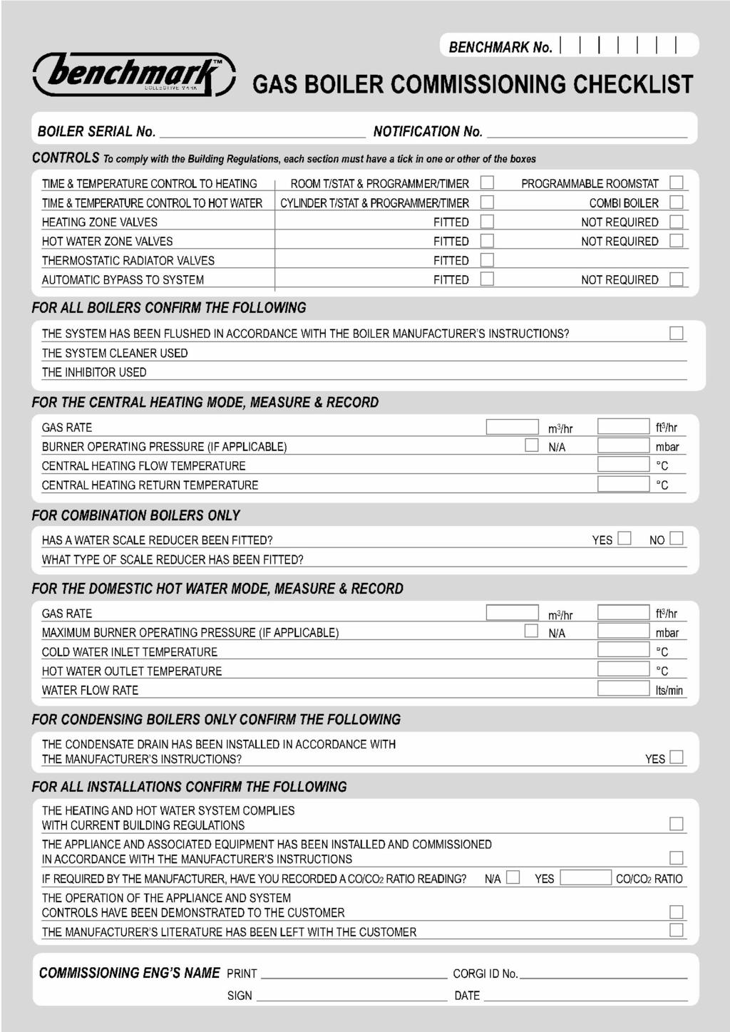
44

45
User manual and Installation instructions
 Wall hung, fan flue, room sealed, high efficiency gas boiler User manual and Installation instructions Models M96.24SM/P M96.28SM/P M96.32SM/P Congratulations on your choice. PARVA HE are condensing high
User manual and Installation instructions
 Wall hung, fanflue, roomsealed, high efficiency gas boiler User manual and Installation instructions GARDA PLUS HE Models G.C. Appl. No. M110B.24SM/E 47---583---13 M110B.32SM/E 47---583---14 Congratulations
User manual and Installation instructions RIVA PLUS. Models: M90D.24S M90D.28S M90D.24SR M90D.28SR
 User manual and Installation instructions RIVA PLUS Models: M90D.24S M90D.28S M90D.24SR M90D.28SR Congratulations on your choice. Your boiler is electronically controlled and has electronic ignition.
User manual and Installation instructions
 Wall hung, fanflue, roomsealed, high efficiency gas boiler User manual and Installation instructions Advance Plus Models G.C. Appl. No. Advance Plus 16S 41-583-22 Advance Plus 25S 41-583-23 Advance Plus
User manual and Installation instructions
 Wall hung, fan flue, room sealed, high efficiency gas boiler User manual and Installation instructions RIVA COMPACT HE Models M96.24SM/C M96.28SM/C M96.28SR/C This product has an energy rating B on a scale
User manual and Installation instructions
 Wall hung, fanflue, roomsealed, high efficiency gas boiler User manual and Installation instructions ActivA Models G.C. Appl. No. Activ A 12OV 41-583-14 Activ A 15OV 41-583-15 Activ A 20OV 41-583-16 Activ
Mikrofill Ethos Condensing combination boiler
 Mikrofill Ethos Condensing combination boiler User Instructions 24cc CE Mark Mikrofill gas appliances comply with the requirements contained in CE Mark documents contained with European directives applicable
User manual and Installation instructions
 Wall hung, fanflue, roomsealed, high efficiency gas boiler User manual and Installation instructions ADVANCE Models G.C. Appl. No. ADVANCE 25C 47-583-43 COMBI BOILER ADVANCE 30C 47-583-44 COMBI BOILER
USERS GUIDE. LOGIC+ Combi 24, 30, 35
 USERS GUIDE LOGIC+ Combi 24, 30, 35 When replacing any part on this appliance, use only spare parts that you can be assured conform to the safety and performance specification that we require. Do not use
Logic+ Combi
 USER GUIDE Logic+ Combi 24 30 35 When replacing any part on this appliance, use only spare parts that you can be assured conform to the safety and performance specification that we require. Do not use
USER GUIDE VOGUE COMBI GEN2 C26 C32 C40
 USER GUIDE VOGUE COMBI GEN2 C26 C32 C40 When replacing any part on this appliance, use only spare parts that you can be assured conform to the safety and performance specification that we require. Do not
Baxi System 100 HE Plus. User s Operating Instructions. Wall Mounted Powered Flue Condensing Gas Fired Central Heating Boiler
 User s Operating Instructions Baxi System 100 HE Plus Wall Mounted Powered Flue Condensing Gas Fired Central Heating Boiler Please keep these instructions safe. Should you move house, please hand them
USER INSTRUCTIONS & CUSTOMER CARE GUIDE Si II SERIES
 24-28Si II SERIES G.C. NUMBERS APPLIANCE NATURAL GAS L.P.G. 24Si II 47 311 65 47 311 66 28Si II 47 311 67 47 311 68 USER INSTRUCTIONS & CUSTOMER CARE GUIDE EXCELLENCE COMES AS STANDARD CONTENTS Page No.
USER GUIDE VOGUE MAX SYSTEM
 USER GUIDE VOGUE MAX SYSTEM 15 18 26 32 When replacing any part on this appliance, use only spare parts that you can be assured conform to the safety and performance specification that we require. Do not
USERS GUIDE 24, 30. For installation guide see reverse of book
 USERS GUIDE 24, 30 For installation guide see reverse of book When replacing any part on this appliance, use only spare parts that you can be assured conform to the safety and performance specification
5 YEAR ADVANCE PLUS WARRANTY. High efficiency condensing combi and system boilers
 5 YEAR WARRANTY ADVANCE PLUS High efficiency condensing combi and system boilers Android Apple WALL HUNG BOILERS Advance Plus ADVANCE PLUS HIGH EFFICIENCY BOILER RANGE The Advance Plus range is the latest
Compact HE. High efficiency combi boiler. Installation & Servicing Instructions THESE INSTRUCTIONS TO BE RETAINED BY USER
 Compact HE High efficiency combi boiler Installation & Servicing Instructions THESE INSTRUCTIONS TO BE RETAINED BY USER Vokèra is a licensed member of the Benchmark scheme which aims to improve the standards
Baxi Maxflow Combi FS
 Baxi Maxflow Combi FS Gas Fired Floor Standing Combination Boiler with Unvented Hot Water Storage Please keep these instructions safe. Should you move house, please hand them over to the next occupier.
System s30. User Guide FAN POWERED HIGH EFFICIENCY MODULATING DOMESTIC CONDENSING GAS SYSTEM BOILER
 System s30 User Guide FAN POWERED HIGH EFFICIENCY MODULATING DOMESTIC CONDENSING GAS SYSTEM BOILER When replacing any part on this appliance, use only spare parts that you can be assured conform to the
Baxi Maxflow Combi WM
 Baxi Maxflow Combi WM Gas Fired Wall Mounted Combination Boiler with Unvented Hot Water Storage Please keep these instructions safe. Should you move house, please hand them over to the next occupier. User
User's Instructions. Alpha CD24C/32C. Range of Wall Mounted, Fan Assisted, Room Sealed, Gas Fired, High Efficiency Condensing Combination Boilers
 User's Instructions Alpha CD24C/32C Range of Wall Mounted, Fan Assisted, Room Sealed, Gas Fired, High Efficiency Condensing Combination Boilers For Technical help or for Service call... ALPHA HELPLINE
Combi C30 & C35. User Guide FAN POWERED HIGH EFFICIENCY MODULATING DOMESTIC CONDENSING GAS COMBINATION BOILER
 Combi C30 & C35 User Guide FAN POWERED HIGH EFFICIENCY MODULATING DOMESTIC CONDENSING GAS COMBINATION BOILER When replacing any part on this appliance, use only spare parts that you can be assured confirm
USERS GUIDE. Esprit eco 24, 30. For installation guide see reverse of book
 USERS GUIDE Esprit eco 24, 30 For installation guide see reverse of book When replacing any part on this appliance, use only spare parts that you can be assured conform to the safety and performance specification
5 YEAR GUARANTEE. Inovia. High efficiency condensing combi and system boilers
 * 5 YEAR GUARANTEE Inovia High efficiency condensing combi and system boilers WALL HUNG BOILERS Inovia INOVIA HIGH EFFICIENCY BOILER RANGE The Inovia range is the latest in intelligent gas boiler technology
The guarantee on this appliance is valid for 12 months from the first day of installation.
 Users Manual Dear Customer, Thank you for choosing an ARISTON boiler. We guarantee that your boiler is a reliable and technically sound product. This Users Manual provides detailed instructions and recommendations
USER GUIDE LOGIC HEAT H
 USER GUIDE LOGIC HEAT H 12 15 18 24 30 When replacing any part on this appliance, use only spare parts that you can be assured conform to the safety and performance specification that we require. Do not
User's Instructions. Alpha CB50
 User's Instructions Alpha CB50 Wall Mounted, Fan Assisted, Room Sealed, Gas Fired Combination Boiler with Unvented Hot Water Storage (From Boiler Serial No. 27B32500001) For Technical help or for Service
USER GUIDE. IMAX XTRA EL kW. For Installation Guide see reverse of book
 USER GUIDE IMAX XTRA EL 320-620kW For Installation Guide see reverse of book When replacing any part on this appliance, use only spare parts that you can be assured conform to the safety and performance
Baxi Combi 133 HE Plus Baxi Combi 100 HE Plus Baxi Combi 80 HE Plus. User s Operating Instructions
 User s Operating Instructions Baxi Combi 133 HE Plus Baxi Combi 100 HE Plus Baxi Combi 80 HE Plus Gas Fired Wall Mounted Condensing Combination Boiler Please keep these instructions safe. Should you move
Compact 24 SE. Standard efficiency combi boiler. Users Instructions. Installation & Servicing Instructions. GC No
 Compact 24 SE Standard efficiency combi boiler Users Instructions Installation & Servicing Instructions GC No. 47-364-06 THESE INSTRUCTIONS TO BE RETAINED BY USER Vokèra is a licensed member of the Benchmark
i 24, i 30, i 35 combination boilers USER GUIDE For Installation Guide see reverse of book UIN A05 October 2017
 24 1 2 23 3 4 5 20 6 I 19 7 18 8 9 15 14 11 13 12 i 24, i 30, i 35 combination boilers USER GUIDE For Installation Guide see reverse of book i 24 OFF MAX E STATUS BURNER RESET MIN PRE MIN MAX HEAT PREHEAT
User's Instructions. Alpha CD25X/28X. Range of Wall Mounted, Fan Assisted, Room Sealed, Gas Fired, High Efficiency Condensing Combination Boilers
 User's Instructions Alpha CD5X/8X Range of Wall Mounted, Fan Assisted, Room Sealed, Gas Fired, High Efficiency Condensing Combination Boilers For Technical help or for Service call... ALPHA HELPLINE Tel:
WHE 2.24 / WHE 2.24 FF
 EN Wall-hung gas boilers WHE 2.24 WHE 2.24 FF User Guide 300011777-001-C . Contents 1 Introduction.............................................................................3 1.1 Symbols used...........................................................................................3
Installation and Servicing Instructions. Alpha CB50
 Installation and Servicing Instructions Alpha CB50 Wall Mounted, Fan Assisted, Room Sealed, Gas Fired Combination Boiler with Unvented Hot Water Storage For Technical help or for Service call... ALPHA
Gas Instantaneous Water Heater
 6 720 607 823 GB (06.06) SM Installation and Operating Instructions Gas Instantaneous Water Heater WR10..B... WR11..B... With electronic ignition and triple safety system consisting of ionisation detector,
Installation and Servicing Instructions. Alpha CD50
 Installation and Servicing Instructions Alpha CD50 Wall Mounted, Fan Assisted, Room Sealed, Gas Fired, High Efficiency, Condensing Combination Boiler with Unvented Hot Water Storage For Technical help
Mikrofill Ethos Condensing combination boiler. Maintenance Instructions 24cc
 Mikrofill Ethos Condensing combination boiler Maintenance Instructions 24cc IMPORTANT Benchmark Installation, Commissioning and Service Record Log Book is enclosed in your customer information pack. This
Baxi Bahama 100. Gas Fired Wall Mounted Combination Boiler. User s Operating Instructions
 Baxi Bahama 100 Please keep these instructions safe. Should you move house, please hand them over to the next occupier. Gas Fired Wall Mounted Combination Boiler User s Operating Instructions Natural Gas
TEMPRA. Wall Mounted Fan Flue System boiler. Wall mounted fanned flue boiler INSTALLATION AND USE INSTRUCTIONS. Appr. nr. B A - CE 0063 AQ 2150
 Wall Mounted Fan Flue System boiler Appr. nr. B 94.04 A - CE 0063 AQ 2150 Phone numbers: Installer Service Engineer Serial N Wall mounted fanned flue boiler INSTALLATION AND USE INSTRUCTIONS Please read
iheat 25c iheat 30c iheat 35c
 iheat 25c iheat 30c iheat 35c Combination Condensing Boilers User Instructions G.C. NUMBER iheat 25c N 47-260-16 iheat 30c N 47-260-17 iheat 35c N 47-260-18 These instructions should be left with the user
Alpha CD13R,18R and 24R
 Installation and Servicing Instructions Alpha CD3R,8R and 24R Wall Mounted, Fan Assisted, Room Sealed, Gas Fired, High Efficiency Condensing Regular Boiler Range For Technical help or for Service call...
Baxi Combi 80Eco. Gas Fired Wall Mounted Combination Boiler. User s Operating Instructions
 Baxi Combi 80Eco Please keep these instructions safe. Should you move house, please hand them over to the next occupier. Gas Fired Wall Mounted Combination Boiler User s Operating Instructions Natural
Performa 24. Gas Fired Wall Mounted Combination Boiler. User s Operating Instructions
 Performa Gas Fired Wall Mounted Combination Boiler User s Operating Instructions Please keep these instructions safe. Should you move house, please hand them over to the next occupier. Natural Gas Potterton
Greenstar 12i/24i System
 USER INSTRUCTIONS & CUSTOMER CARE GUIDE Greenstar 12i/24i System WALL HUNG GAS-FIRED CONDENSING SYSTEM BOILER FOR SEALED CENTRAL HEATING SYSTEMS & INDIRECT FED DOMESTIC HOT WATER THIS BOILER IS USED WITH
Greenstar 25Si/30Si USER INSTRUCTIONS & CUSTOMER CARE GUIDE
 USER INSTRUCTIONS & CUSTOMER CARE GUIDE Greenstar 25Si/30Si WALL HUNG GAS-FIRED CONDENSING COMBINATION BOILER FOR SEALED CENTRAL HEATING SYSTEMS & DOMESTIC HOT WATER THIS BOILER IS USED WITH NATURAL GAS
Heat 45 & 55. User Instructions FAN POWERED HIGH EFFICIENCY MODULATING DOMESTIC CONDENSING GAS COMBINATION BOILER
 Heat 45 & 55 User Instructions FAN POWERED HIGH EFFICIENCY MODULATING DOMESTIC CONDENSING GAS COMBINATION BOILER CE/PI No. 86-CN-69 Heat 45 - GC No. 41-930-40 Heat 55 - GC No. 41-930-41 These instructions
GREENSTAR HIGHFLOW 440/550CDi
 FLOOR STANDING RSF GAS-FIRED CONDENSING COMBINATION BOILER GREENSTAR HIGHFLOW 440/550CDi FOR SEALED CENTRAL HEATING SYSTEMS AND MAINS FED DOMESTIC HOT WATER THE APPLIANCE IS FOR USE WITH NATURAL GAS OR
Installation and Servicing Instructions
 Installation and Servicing Instructions Alpha HE CB25/33 and HE SY25 Wall Mounted, Fan Assisted, Room Sealed, Gas Fired, High Efficiency Condensing Boiler Range For Technical help or for Service call...
Open Vented Condensing Boilers
 Dimplex 18 OV Dimplex 32 OV Open Vented Condensing Boilers User s Operating Instructions These instructions should be left with the user Dimplex Boilers 2008 CONTENTS SECTION DESCRIPTION PAGE 1.0 Using
USERS MANUAL FOR GAS BOILERS
 USERS MANUAL FOR GAS BOILERS PLEASE READ THE MANUAL CAREFULLY: IT CONTAINS IMPORTANT INFORMATION REGARDING SAFETY, INSTALLATION, USE AND MAINTENANCE OF THE APPLIANCE MODELS: NOVADENS 24 NOVADENS 24C NOVADENS
Ultracom cxi. Instructions for Use. High Efficiency Condensing System Boilers. To b e l e f t w i t h t h e u s e r.
 Ultracom cxi High Efficiency Condensing System Boilers Instructions for Use To b e l e f t w i t h t h e u s e r WARNING GAS LEAK OR FAULT Turn off the gas emergency control valve immediately. Eliminate
Residential Gas Condensing Boiler Greenstar ZBR16/21/28/35/42-3A... ZWB28/35/42-3A...
 70 80 99-00-O Residential Gas Condensing Boiler ZBR//8/35/4-3A... ZWB8/35/4-3A... 70 80 993 (03/03) CA/US Operating Instructions Contents Contents Key to symbols and safety instructions............................
24CDi, 28CDi & 35CDi II COMBI
 Vote for your Installer of the year at www.worcester-bosch.co.uk 24CDi, 28CDi & 35CDi II COMBI Worcester supports the Benchmark code of practice G.C. NUMBERS APPLIANCE NATURAL GAS L.P.G. 24CDi Fanned Flued
GB24 & GB30. User Manual
 GB24 & GB30 User Manual BOILER OUTPUT To Domestic Hot Water:To Central Heating: GB24/30 Minimum 8.0 kw (27,296 Btu/h) GB24 Maximum 24.2 kw (82,570 Btu/h) GB30 Maximum 30.3 kw (103,384 Btu/h) GB24/30 Minimum
Compact. Installation & Servicing Instructions THESE INSTRUCTIONS TO BE RETAINED BY USER
 Compact Installation & Servicing Instructions THESE INSTRUCTIONS TO BE RETAINED BY USER Contents Design principles and operating sequence Page 1.1 Principle components 2 1.2 Central heating mode 2 1.3
Service manual. Riva Plus HE. M296.28SR/C System boiler. Wall hung, fanflue, roomsealed, high efficiency gas boiler
 Wall hung, fanflue, roomsealed, high efficiency gas boiler Service manual Riva Plus HE Models G.C. ppl. No. M296.24SR/C 41-583-18 System boiler M296.28SR/C 41-583-19 System boiler Leave this manual adjacent
USER INSTRUCTIONS & CUSTOMER CARE GUIDE HIGHFLOW 400 ELECTRONIC SERIES
 HIGHFLOW 400 ELECTRONIC SERIES G.C. NUMBERS APPLIANCE NATURAL GAS L.P.G. Fanned Flue (RSF) 47 311 61 47 311 64 Balanced Flue (BF) 47 311 62 Open Flue (OF) 47 311 63 USER INSTRUCTIONS & CUSTOMER CARE GUIDE
INSTALLATION AND MANINTENANCE INSTRUCTIONS
 INSTALLATION AND MANINTENANCE INSTRUCTIONS Appr. Nr. A 9503 T - 0085 AQ 0765 PEGASUS F2 T HIGH EFFICIENCY GAS-FIRED CAST-IRON BOILERS Models 51-68 - 85-102 2 Contents 1. General technical data 2. Dimensional
Installation and Servicing Instructions. Alpha CD24C/32C
 Installation and Servicing Instructions Alpha CD24C/32C Range of Wall Mounted, Fan Assisted, Room Sealed, Gas Fired, High Efficiency Condensing Combination Boilers For Technical help or for Service call...
Installation, Servicing and Operating Instructions. Type C Boilers LEAVE THESE INSTRUCTIONS WITH THE END USER
 Installation, Servicing and Operating Instructions Type C Boilers COMBI A 24 MFFI G.C.N: 47-116-44 COMBI A 30 MFFI G.C.N: 47-116-45 LEAVE THESE INSTRUCTIONS WITH THE END USER Country of destination: GB/IE
CONDENSING COMBINATION BOILER. Installation, Servicing and User Instructions
 SARGON 24 / 30 / 35 PRE-MIX CONDENSING COMBINATION BOILER Installation, Servicing and User Instructions Natural Gas Heatline Sargon 24 / 30 / 35 Pre-mix Condensing Combination Boiler British Gas Service
Wall hung combination boilers. This is a CAT II2H3+ appliance USER, INSTALLATION AND SERVICING INSTRUCTIONS SUPPORTED BY
 Wall hung combination boilers This is a CAT II2H3+ appliance SUPPORTED BY USER, INSTALLATION AND SERVICING INSTRUCTIONS Index Introduction... 3 User instructions...3 Introduction... 4 Controls and lighting...
Vote for your Installer of the year at. 9/14, 14/19 & 19/24CBi. Worcester supports the Benchmark code of practice
 Vote for your Installer of the year at www.worcester-bosch.co.uk 9/14, 14/19 & 19/24CBi Worcester supports the Benchmark code of practice G. C. NUMBERS APPLIANCE NATURAL GAS LPG 9/14CBi 41 311 50 41 311
MULTIPOINT BF Gas Fired Balanced Flue Water Heater
 Please leave these instructions with the user MULTIPOINT BF Gas Fired Balanced Flue Water Heater User Operating, Installation and Servicing Instructions 6 720 607 090 (03.12) JS Natural Gas Main Multipoint
Unvented Calorifier Range. Operating and Maintenance Manual. For Models & 500
 Unvented Calorifier Range. Operating and Maintenance Manual. For Models 125 300 & 500 Telephone 08456 448802 Fax 08456 448803 Emial info@mhgheating.co.uk Web www.mhgheating.co.uk TABLE OF CONTENTS. Section
Operating instructions
 The energy you need Operating instructions Betacom 3 24c -A (H-GB) 30c -A (H-GB) GB, IE Contents Contents 1 Safety... 3 1.1 Action-related warnings... 3 1.2 Intended use... 3 1.3 General safety information...
CBX 24, 32 & 38 SBX 30
 751030 MANUAL (NEW) 21/9/10 08:39 Page 1 Eden X Type CBX 24, 32 & 38 SBX 30 INSTALLATION AND SERVICING INSTRUCTIONS TO BE GIVEN TO THE USER 0086 EC 87/BP/35 G.C. Appliance No. 47-260-05 (Eden CBX 24) G.C.
JANUS 3 CIRCULATOR WATER HEATER INSTALLATION, COMMISSIONING & SERVICING INSTRUCTIONS G.C. No
 JANUS 3 CIRCULATOR WATER HEATER INSTALLATION, COMMISSIONING & SERVICING INSTRUCTIONS G.C. No 53 416 06 Publication No. ZZ 180/17 May 2000 These appliances are tested and certified by B G Technology for
Osprey 2 CFL
 Osprey 2 CFL 125-150 - 180-220 Gas Fired Floor Standing Boiler Users Operating Instructions Please leave these instructions with the user Natural Gas Potterton Osprey 2 CFL 125 G.C.N o 41 590 54 Potterton
condens Instructions for Use Betacom 2 24 G.C. No Betacom 2 28 G.C. No
 condens Instructions for Use Betacom 2 24 G.C. No. 47-019-16 Betacom 2 28 G.C. No. 47-019-17 table of contents READ CAREFULLY BEFORE USING 1 Read me...3 1.1 Welcome... 3 1.2 Guarantee Pack... 3 1.3 Servicing...
Installation and Servicing Instructions. Alpha 240/280. Range of Wall Mounted, Fan Assisted, Room Sealed, Gas Fired Combination Boilers
 Installation and Servicing Instructions Alpha 240/280 Range of Wall Mounted, Fan Assisted, Room Sealed, Gas Fired Combination Boilers For Technical help or for Service call... ALPHA HELPLINE Tel: (0322)
British Gas 330+ High Efficiency Condensing Boiler. Instructions for Use. To b e l e f t w i t h t h e u s e r. British Gas Service Tel:
 0020051423-02 10.07 British Gas 330+ High Efficiency Condensing Boiler Instructions for Use To b e l e f t w i t h t h e u s e r British Gas Service Tel: 0845 9500400 WARNING GAS LEAK OR FAULT Turn off
Ultracom 2. sxi. Instructions for Use. 12sxi. 18sxi. 30sxi. High Efficiency Condensing System Boilers. To be left with the user. G.C. No.
 Ultracom 2 sxi Instructions for Use To be left with the user 12sxi G.C. No. 41-019-12 18sxi G.C. No. 41-019-13 30sxi G.C. No. 41-019-14 High Efficiency Condensing System Boilers www.glow-worm.co.uk TABLE
kw Btu/h Metres Feet l/min. Gal/min C C
 80ic RSF WALL MOUNTED COMBINATION BOILER FOR CENTRAL HEATING AND MAINS FED DOMESTIC HOT WATER INSTALLATION AND SERVICING INSTRUCTIONS 6 720 605 553 PT 2000 11 Cat: II 2H3+ GC NUMBER NG: 47 311 43 LPG:
ProCon Streamline Gas Condensing Boiler. Installation and Operating Manual.
 1 MHG Heating Ltd ProCon Streamline Gas Condensing Boiler. Installation and Operating Manual. Unit 4 Epsom Downs Metro Centre, Waterfield, Tadworth, Surrey, KT20 5LR Telephone 08456 448802 Fax 08456 448803
Instructions for Use Installation and Servicing
 0020004886A 18.01.05 Instructions for Use Installation and Servicing To be left with the user 12563 115-150-175-200-250-300 Unvented hot water storage cylinders Glow-worm, Nottingham Road, Belper, Derbyshire.
E-COMBI EVO E-SYSTEM EVO
 E-COMBI EVO E-SYSTEM EVO User s manual CONDENSING WALL-HUNG GAS BOILER G.C.N.:47-116-68 (24 kw) G.C.N.:47-116-69 (30 kw) G.C.N.:47-116-70 (38 kw) G.C.N.:41-116-39 (24 kw) G.C.N.:41-116-40 (30 kw) Country
Greenstar 12i system / 24i system
 Greenstar 12i system / 24i system WALL HUNG GAS-FIRED CONDENSING SYSTEM BOILER FOR SEALED CENTRAL HEATING SYSTEMS & INDIRECT FED DOMESTIC HOT WATER THIS APPLIANCE IS FOR USE WITH NATURAL GAS OR LPG (Cat
Operating instructions
 Operating instructions Capriz 2 24c 28c GB, IE Contents Contents 1 Safety... 3 1.1 Action-related warnings... 3 1.2 Intended use... 3 1.3 General safety information... 4 2 Notes on the documentation...
WARMCAIR. Condensing Air & Water Heater. High Efficiency Downflow Condensing Air & Water Heater USERS INSTRUCTIONS
 WARMCAIR Condensing Air & Water Heater Publication No. ZZ 1449-2 September 2016 High Efficiency Downflow Condensing Air & Water Heater USERS INSTRUCTIONS Warmcair C10DW - G.C. No. 43-417-59 Warmcair C16DW
Ultracom hxi. Instructions for Use. High Efficiency Condensing System Boilers. To b e l e f t w i t h t h e u s e r.
 Ultracom hxi High Efficiency Condensing System Boilers Instructions for Use To b e l e f t w i t h t h e u s e r WARNING GAS LEAK OR FAULT Turn off the gas emergency control valve immediately. Eliminate
SIME FORMAT WALL HUNG BOILERS MODEL 34i AND MODEL 34e. cod A
 cod. 6272262A GENERAL DATA Heating Data Heat Output Input (Adjustable) (Adjustable) Format 34i 11.2 34KW 45 145MJ/hr Format 34e 11.2 34KW 45 145MJ/hr General Specifications FORMAT 34i 34e Main burner injectors
Supplied by HeatingSpares247.com
 Users Guide Installation and Servicing Instructions G.C. Number 47-6-30 G.C. Number 47-6-3 Manufacturered by Merloni TermoSanitari spa - Italy Country of destination: GB - IE TABLE OF CONTENTS USERS GUIDE.
Mynute. Installation & Servicing Instructions. 28e THESE INSTRUCTIONS TO BE RETAINED BY USER
 28e Installation & Servicing Instructions THESE INSTRUCTIONS TO BE RETAINED BY USER Contents Design principles & operating sequence Page 1.1 Principle components 2 1.2 Mode of operation 2 1.3 Safety devices
Powermax HE 85, 115 & 150 Litre Condensing Boilers with Integrated Hot Water Storage
 User s Instructions Quick Guide to the Controls When the Powermax was installed, the Installer should have - left or given you these and other instructions including the Benchmark Log Book and Potterton
WALL-HUNG HIGH EFFICIENCY GAS BOILERS. Elegant, efficient and intelligent
 CLAS HE WALL-HUNG HIGH EFFICIENCY GAS BOILERS Elegant, efficient and intelligent The high efficiency boiler that saves on energy and costs With specified intelligence, CLAS HE adapts to the householder's
Operating instructions
 Operating instructions For the operator Operating instructions HOME SYSTEM GB, IE Publisher/manufacturer Vaillant GmbH Berghauser Str. 40 D-42859 Remscheid Tel. +49 21 91 18 0 Fax +49 21 91 18 28 10 info@vaillant.de
TAHITI CONDENSING KR 55 - KR 85
 IST 03 C 351-01 TAHITI CONDENSING KR 55 - KR 85 GB INSTALLATION USE AND MAINTENANCE Dear Customer, Thank you for choosing and buying one of our boilers. Please read these instructions carefully. They will
SERVICE MANUAL RIVA COMPACT M90E.24S M90E.28S M90E.32S Wall hung, fan flue, room sealed gas boiler
 Wall hung, fan flue, room sealed gas boiler SERVICE MNUL RIV COMPCT Models: G.C. ppl. No. M90E.24S 47--970--17 M90E.28S 47--970--18 M90E.32S 47--970--21 Leave this manual adjacent to the gas meter iasi
OWNER GUIDE. Model 750. INSET LIVE FUEL EFFECT GAS FIRE Fitted with Harmony, Avignon or Style fascia. (GC No )
") 5112499/01 OWNER GUIDE Model 750 INSET LIVE FUEL EFFECT GAS FIRE Fitted with Harmony, Avignon or Style fascia (GC No. 32-032-58) THIS APPLIANCE IS FOR USE WITH NATURAL GAS (G20) WHEN CONVERTED USING CONVERSION
5112499/01 OWNER GUIDE Model 750 INSET LIVE FUEL EFFECT GAS FIRE Fitted with Harmony, Avignon or Style fascia (GC No. 32-032-58) THIS APPLIANCE IS FOR USE WITH NATURAL GAS (G20) WHEN CONVERTED USING CONVERSION
Service manual GARDA HE MK2. M96A.24SM/B Combi boiler M96A.28SM/B Combi boiler
 Wall hung, fan flue, room sealed, high efficiency gas boiler Service manual GRD HE MK2 Models: G.C. ppl. No. M96.24SM/ 47---583---15 Combi boiler M96.28SM/ 47---583---16 Combi boiler Leave this manual
Linea ONE. High efficiency combi boiler. Installation & Servicing Instructions THESE INSTRUCTIONS TO BE RETAINED BY USER
 Linea ONE High efficiency combi boiler Installation & Servicing Instructions THESE INSTRUCTIONS TO BE RETAINED BY USER Vokèra is a licensed member of the Benchmark scheme which aims to improve the standards
User Manual FLOWMAX-90. for model. Condensing water heater 85,000 BTU. Installation, operating, commissioning and maintenance instructions.
 User Manual for model FLOWMAX-90 Condensing water heater 85,000 BTU WARNING If the information in these instructions is not followed exactly, a fire or explosion may result, causing property damage, personal
This is a Wall Mounted Powered Flue Condensing Combination Boiler Gas Fired Central Heating Unit.
 Installation & Service Instructions Performa System HE This is a Wall Mounted Powered Flue Condensing Combination Boiler Gas Fired Central Heating Unit. The boiler meets the requirements of Statutory Instrument
With a power output ranging from 13kW to 24kW, they provide the flexible answer for the majority of traditional installation scenarios.
 Alpha Regular Boilers CDR Range CDR heating-only boilers are for use on open-vented or using the Alpha sealed system kit sealed systems. When fitted with a storage cylinder, they are capable of supplying
FEB-24E UK SUPERCOMPACT COMBINATION BOILER USER MANUAL
 FEB-24E UK SUPERCOMPACT COMBINATION BOILER USER MANUAL Morco Products Ltd Riverview Road, Beverley, East Yorkshire, HU17 0LD Telephone 01482 325456 Fax 01482 212869 1 2 CONTENTS Section Page 1 USERS INSTRUCTIONS
Riva ADVANCE COMBI USER MANUAL AND INSTRUCTIONS WALL HUNG GAS BOILER FOR CENTRAL HEATING SUPPLY
 USER MANUAL AND INSTRUCTIONS Riva ADVANCE COMBI WALL HUNG GAS BOILER FOR CENTRAL HEATING SUPPLY Please Read Instructions Carefully Save for Future Reference WARNING: If the information in this manual is
WALL-HUNG HIGH EFFICIENCY GAS COMBINATION BOILERS. Efficient, economical and easy
 E-COMBI WALL-HUNG HIGH EFFICIENCY GAS COMBINATION BOILERS Efficient, economical and easy Reliable, advanced Easy to install Easy installation, commissioning and servicing The E-COMBI range has been designed
Instructions for Use Installation and Servicing To be left with the user
 Instructions for Use Installation and Servicing To be left with the user 2000225000B.02.02 23c 10139 Fanned Flue Combination Boiler G.C. No. 47-047-18 This is a Cat I 2H Appliance The instructions consist
Mynute 24m Installation & Servicing Instructions
 Mynute 24m Installation & Servicing Instructions THESE INSTRUCTIONS TO BE RETAINED BY USER Contents Design principles & operating sequence Page 1.1 Principle components 2 1.2 Mode of operation 2 1.3 Safety