INSTALLATION OPERATION AND SERVICE MANUAL
|
|
|
- Quentin Chandler
- 5 years ago
- Views:
Transcription


1 INSTALLATION OPERATION AND SERVICE MANUAL ADVANTUS SERIES GAS FIRED FIRE TUBE COMMERCIAL CONDENSING STAINLESS STEEL BOILERS HYDRONIC HEATING Models; AVH 500, 600, 800, 1000, 1200, 1400, 1600, 1800, 2000, 2500, 3000, 3500, 4000 HOT WATER HEATER Models; AVW 500, 600, 800, 1000, 1200, 1400, 1600, 1800, 2000, 2500, 3000, 3500, 4000 H HLW WARNING: If the information in these instructions is not followed exactly, a fire or explosion may result causing property damage, personal injury or death. Do not store or use gasoline or other flammable vapors and liquids in the vicinity of this or any other appliance. WHAT TO DO IF YOU SMELL GAS: Do not try to light any appliance, Do not touch any electrical switch; do not use any phone in your building, Immediately call your gas supplier from a neighbor s phone. Follow the gas supplier s instructions, If you cannot reach your gas supplier, call the fire department. Only a Qualified installer, service agency or the gas supplier must perform installation and service. To the Installer: After installation, these instructions must be given to the end user or left on or near the appliance. To the End User: This booklet contains important information about this appliance. Retain for future reference Netherhart Road Mississauga, Ontario L5T 1B7 Canada P: F: REV.01
2
3 Table of Contents PART 1 GENERAL INFORMATION INTRODUCTION SPECIAL INSTRUCTIONS TO OWNER CHECKING EQUIPMENT HOW IT OPERATES (SEQUENCE OF OPERATION) HEAT TRANSFER PROCESS END OF SEQUENCE CODES WARRANTY REMOVAL OF EXISTING APPLIANCE BOILER ROOM OPERATING CONDITION CLEARANCE FROM COMBUSTIBLE MATERIAL INSTALLATION PROCEDURE AND LOCATION OF UNIT... 7 PART 2 VENTING & AIR SUPPLY GENERAL VENTING GUIDE CATEGORY II AND CATEGORY IV VENTING VENTING GUIDELINES FOR CATEGORY II AND/OR IV VENTING APPROVED VENTING MATERIALS VENT TERMINATION CLEARANCES INLET CAP FOR ROOFTOP TERMINATION LOCATION OF A ROOFTOP AIR INLET AND VENT CAPS AIR INLET DAMPER MASONRY CHIMNEY INSULATIONS VERTICAL VENTING TERMINATION COMBINED COMBUSTION AIR INLET DRAIN TEE CONVENTIONAL VENTING (INDOOR) INSTALLATIONS AIR REQUIRED FOR COMBUSTION AND VENTILATION EXHAUST FANS OUTDOOR VENTING SIDEWALL VENTING SIDEWALL VENT TERMINAL & SIDEWALL INTAKE AIR TERMINAL LOCATION OF A SIDEWALL VENT TERMINATION LOCATION OF A SIDEWALL AIR INLET TERMINAL LENGTH OF AIR INLET PIPE PART 3 GAS CONNECTIONS GAS CONNECTION GAS PIPING INSTALL PIPING AIR/GAS RATIO VALVE... 19
4 3.5 OPERATION OF NEGATIVE PRESSURE AND DIFFERENTIAL PRESSURE VALVES GAS MANIFOLD DIFFERENTIAL PRESSURE ADJUSTMENT (AV1000-AV4000) CHECKING GAS SUPPLY PRESSURE REGULATED GAS SUPPLY PRESSURES FOR ADVANTUS BOILERS & WATER HEATERS CHECKING DIFFERENTIAL AIR AND GAS PRESSURES (AV800-AV4000) GAS TRAIN AND CONTROLS VENTING OF GAS VALVES AND PRESSURE SWITCHES BURNER PART 4 WATER CONNECTION FREEZE PROTECTION WARNING REGARDING CHILLED WATER AND HEATING COIL SYSTEMS INLET AND OUTLET CONNECTIONS MINIMUM PIPE SIZE REQUIREMENTS HEAT EXCHANGER LOW WATER TEMPERATURE SYSTEMS INSTANTANEOUS WATER HEATER WATER HEATER THERMOSTAT SETTING WATER FLOW SWITCH (shipped loose) LOW WATER CUTOFF (If Equipped) RELIEF VALVE CIRCULATING PUMP SELECTION CIRCULATING PUMP OPERATION OF HEAT EXCHANGER T HEAT EXCHANGER ALGORITHM PART 5 ELECTRICAL & CONTROLS ELECTRICAL CONNECTIONS VARIABLE FREQUENCY DRIVE (AV ) LOW AIR DIFFERENTIAL PRESSURE SWITCH BLOCKED FLUE SWITCH HIGH AND LOW GAS PRESSURE SWITCHES HIGH LIMIT Advantus SOLA SERVICE PARTS IGNITION MODULE LOCKOUT FUNCTIONS Advantus CONTROLLER ERROR TABLE PART 6 CONTROL PANEL APPLIANCE TEMPERATURE CONTROLLER CONFIGURE MENU SYSTEM IDENTIFICATION & ACCESS PUMP CONFIGURATION STATISTICS CONFIGURATION... 49
5 6.2.4 BURNER CONTROL TIMING AND RATES BURNER CONTROL IGNITION SENSOR CONFIGURATION LEAD LAG SETUP LOCAL/REMOTE SWITCH MODBUS, BACNET IP, BACNET MSTP, LONWORKS, METASYSN2 INTEGRATION VARIABLE FREQUENCY DRIVE (AV ) FROST PROTECTION PART 7 COMPONENTS HOT SURFACE IGNITOR (GLOW BAR) UV SCANNER STAGING RELAY OUTER JACKET VENTING TRANSITION CONDENSATION COLLECTION COMBUSTION AIR FAN PART 8 FIELD STARTUP PROCEDURES CHECKING THE INSTALLATION CHECKING THE CONSTRUCTION GAS VALVE ADJUSTMENT PROCEDURE COMISSIONING APPLIANCE PART 9 TROUBLESHOOTING PART 10 MAINTENANCE EXAMINE THE VENTING SYSTEM VISUALLY CHECK MAIN BURNER FLAMES FLUE GAS PASSAGEWAYS CLEANING PROCEDURES CONDENSATION TREATMENT CONDENSATE VOLUME BURNER MAINTENANCE BURNER REMOVAL BURNER CLEANING PROCEDURE CHANGING THE HOT SURFACE IGNITER RE-INSTALLING THE IGNITER HEAT EXCHANGER INSPECTION RE-INSTALL HEAT EXCHANGER COMBUSTION AIR FAN COMBUSTION AND VENTILATION AIR CONTROL CIRCUIT VOLTAGE COMBUSTIBLE MATERIALS FREEZE PROTECTION FREEZE PROTECTION FOR A HEATING BOILER SYSTEM (Optional)... 74
6 PART 11 INSTALLATIONS CHECKING THE INSTALLATION CHECKING THE INSTALLTION INSPECT & RECHARGE CONDENSATE COLLECTION & NEUTRALIZING RESERVOIR HEATING BOILER INSTALLATIONS WATER CONNECTIONS PIPING LENGTHS INTERMITTENT PUMP OPERATION SUMMARY DOMESTIC HOT WATER HEATER WATER THERMOSTAT SETTING WATER FLOW CONTROL TEMPERATURE RISE AT FULL FIRING RATE WATER HEATERS PART 12 EXPLODED VIEW CONDENSING BOILER LIMITED WARRANTY... 95

7 PART 1 GENERAL INFORMATION 1.1 INTRODUCTION The Advantus is a condensing, forced draft, fire tube appliance utilizing a premix power burner based on a push through design which offers several venting options. Heat output is controlled by air/gas ratio control gas valves which provide seamless modulation. The Advantus provides central heating or domestic hot water at working pressures up to 160 PSI. It is designed for use with a pumped and pressurized system. The boiler/water heater will automatically modulate to provide heat outputs between 100% and down to 10% for models AV500 & AV600 and down to 4.5% for models AV800 to AV1800 and 4.0% for models AV2000 to AV4000. The Advantus models 500 & 600 use a single automatic gas valve and operate on the principle of negative pressure. As the fan varies in speed it generates a varying negative pressure at the fan suction which draws in a corresponding amount of gas. The Advantus models use two automatic gas valves - one at the low end and one at the high end. The High-End Gas Valve works on the principle of differential pressure. Operation of the fan generates a differential air pressure, which the air/gas ratio control gas valve matches on the gas side. The steady state efficiency is maintained across the entire range of modulation. Air and gas are metered in precise proportion (1:1 Ratio) to modulation signal, allowing combustion characteristics which determine efficiency to remain the same over the entire operating range. The low end the gas valve works on the principle of negative pressure. Figure 1: Advantus 1.2 SPECIAL INSTRUCTIONS TO OWNER This manual supplies information for the installation, operation and servicing of the appliance. It is strongly recommended that this manual be reviewed completely before proceeding with an installation. CAUTION It is important that all gas appliances are installed by a qualified installer/technician that is trained by Camus Hydronics Limited. It is in your own interest and that of safety to ensure that all local codes, and all the following NOTES and WARNINGS are complied with. Installing, servicing or adjusting this appliance should be performed only by a qualified installer/technician that is trained by Camus Hydronics Limited. The serviceman must utilize a combustion analyzer with CO2, CO, and draft gauge to set the appliance according to Camus Hydronics Limited s recommendations, prior to commissioning. NOTE RETAIN THIS MANUAL FOR FUTURE REFERENCE 1

8 1.3 CHECKING EQUIPMENT Check for signs of shipping damage upon receiving equipment. Pay particular attention to parts accompanying the boiler, which may show signs of being hit or otherwise being mishandled. Verify total number of pieces shown on packing slip with those actually received. In case there is damage or a shortage, immediately notify carrier. Figure 2: Checking the Advantus Do not attempt to pry any panel off. To begin disassembly, you must first remove the two top panels (which can be lifted off without the use of tools). Only then will you be able to remove the front and two side panels. Once you have removed the two top panels, carefully check and confirm that all ¼ copper tubing connections are intact and have not broken or loosened in shipment. Leaks at any connections on these lines will result in erratic appliance operation. 1.4 HOW IT OPERATES (SEQUENCE OF OPERATION) 1. Supply power connection as per table The power switch is placed in the ON position VAC power is supplied to the control transformer VAC is supplied to the ignition module and low voltage controls for all models. 5. After the appliance water pump starts, flow is proven by the Flow Switch and Water Pressure Switch. The Water Pressure Switch is set to close at 30 PSI and is installed in the unit. The Flow Switch is mounted at the outlet of the appliance. If installing a Flow Switch, take care to properly trim the Flow Switch Paddles so as not to jam the switch in the tee. The normally open dry contacts in the Low Water Cutoff (LWCO) are to be wired in series with the normally open contacts of the Flow Switch. Locate the probe type LWCO in the piping above the boiler inlet/outlet connection. In all cases, check with local codes. 6. The Advantus controller receives a call for heat via the remote operator contacts and the Demand parameter reads Central Heating, DHW, or Lead Lag Slave. 7. a) AV500-AV600: The Advantus controller energizes the pump contacts and starts to ramp up the voltage to the EC DC motor of the Combustion Fan after internal safety checks are satisfied. b) AV800-AV4000: The Advantus controller closes the pump contacts to start the pump which then causes the Flow Switch to close once minimum flow is reached. If all limit controls are made including temperature, water pressure and water flow, the controller closes the blower contacts to initiate the VFD and allows 60 seconds for the variable frequency drive (VFD) to ramp up the frequency to the 3 phase motor of the Combustion Fan using the modulating signal provided by the on board modulating control or the remote operating system. If the Low Air Switch contacts are made within the 60 seconds, the VFD will run at Pre-Purge speed until the Pre-Purge timer is satisfied. 8. Once the Pre-Purge Timer is satisfied, the Advantus controller will target the ignition fan speed. 9. a) AV500-AV600 (Direct Ignition): The Hot Surface Igniter will be energized for 22 seconds followed by opening of the gas valve. A signal of 0.8 Vdc minimum must be recognized by the controller at the UV Scanner to keep the gas valve in an open position. The fan is kept at ignition speed as long as it receives a minimum modulation signal. As demand increases the modulation signal increases until full fire is reached. As target temperature is approached, the demand signal is reduced and the gas valve modulates downwards. b) AV800 AV2500 (Direct Ignition): The Advantus controller will activate the Hot Surface Igniter for 28 seconds followed by energizing the Low-End Gas Valve. A signal of 0.8 Vdc minimum must be recognized by the controller at the UV Scanner to keep the Low-End Gas Valve in the open position. The fan is kept at ignition speed until the flame is stabilized. As demand increases the modulation signal causes the Low-End Gas Valve to draw more gas. If the Low-End Gas Valve cannot satisfy demand, at a preset point the staging relay activates the hot surface igniter to provide seamless transition to the high end gas valve. The fan inlet damper opens and directs power to the High-End Gas Valve while shutting off the Low-End Gas Valve. 2
9 As target temperature is approached the demand signal is reduced and at a pre-set point the hot surface ignitor is activated, the High-End Gas Valve shuts off and the Low-End Gas Valve is energized. At the same time the fan inlet damper is closed. As demand continues to decrease the low end gas valve shuts off and the boiler proceeds to post purge. c) AV AV4000 (Proven Pilot): The Advantus controller will activate the Hot Surface Igniter for 22 seconds followed by energizing the Pilot Valve for 10 seconds, whereupon a signal of 0.8 Vdc must be recognized by the controller at the UV Scanner to keep the Pilot Valve in an open position. The fan is kept at ignition speed until the stabilization timer is satisfied. After the stabilization timer expires the Low-End Gas Valve is opened and the Pilot Valve is deactivated. As demand increases, the modulation signal causes the Low-End Valve to draw more gas and the sequence as detailed in (b) above is followed. 10. If the flame signal is not reached, the module will stop the ignition sequence after the Main Gas On period & recycle. 11. The fan speed will slowly decrease as the temperature nears the target. The modulation rate is controlled via a 4-20 ma signal. If the heat demand is sustained without change, the boiler firing rate will reach a point of steady-state and the fan will rotate at constant speed. 12. When the heat demand is satisfied or the remote enable is removed, the burner will shut off and the fan speed will ramp up to the preset Post-Purge speed until the Post-Purge timer is satisfied. 13. The pump continues to circulate until the Post-Purge time is satisfied. 14. The boiler will then go into Standby as it waits for the next heat demand or remote enable. NOTE The Hot Surface Igniter is energized with 115V AC when control is switching to/from the High-End Gas Valve to the Low-End Gas Valve. To avoid shock do not contact bare Ignitor wires at this time Figure 3: Advantus Ignition Cycle NOTE: 1. If a flame signal is detected at the end of the Pre-Purge period, an error will occur. 2. If at the end of the safety period (4 sec) no flame is detected, the control will go to Post-Purge to remove the unburned gas. After this, a re-ignition attempt is started following the same cycle. The number of re-ignition attempts is Limited to 2 after which a lockout occurs. 3. The burner can only be on continuously for a period of 24 hours. After this, the burner is switched off and a restart sequence follows. 4. The Hot Surface Igniter is de-energized at the end of the ignition period to allow for ionization detection HEAT TRANSFER PROCESS 1. Burner input rate continues to increase until water temperature reaches the set point temperature. 2. Burner input rate may stabilize at a fixed rate when demand equals input. 3. Burner input rate will decrease when water temperate approaches temperature set point END OF SEQUENCE 1. Set point temperature is reached. 2. Power to the gas valve is turned off. 3
10 3. Combustion air fan ramps to a stop over the factory pre-programmed time period. 4. Thermostat is now in a standby mode waiting for the next Call for Heat. WARNING To minimize the possibility of serious personal injury, fire or damage to your appliance, never violate the following safety rules. WARNING IMPROPER INSTALLATION, ADJUSTMENT, ALTERATION, SERVICE OR MAINTENANCE can cause injury or property damage. Refer to this manual. For additional information, consult a qualified installer, service agency or gas supplier. DO NOT Do not use this appliance if any part of it has been under water. The possible damage to a flooded appliance can be extensive and present numerous safety hazards. Any appliance that has been under water must be replaced. WHAT TO DO IF YOU SMELL GAS Do not try to light any appliance. Do not touch any electric switch. Do not use any phone in your building. Immediately call your gas supplier from a neighbor s phone. Follow the gas supplier s instructions. If you cannot reach your gas supplier, call the fire department. IMPORTANT Consult and follow local Building and Fire Regulations and other Safety Codes that apply to this installation. Contact the local gas utility company to authorize and inspect all gas and flue connections. Installation and service must be performed by Camus Hydronics Limited qualified factory trained service technicians. WARNING Should overheating occur or the gas supply fails to shut off, DO NOT turn off or disconnect the electrical supply to the pump. Shut off the gas supply at a location external to the appliance. Boilers and water heaters are heat producing appliances. To avoid damage or injury, do not store materials against the appliance or the vent-air intake system. Use proper care to avoid unnecessary contact (especially children) with the appliance and vent-air intake components. Never cover your appliance, lean anything against it, store trash or debris near it, stand on it or in any way block the flow of fresh air to your appliance. UNDER NO CIRCUMSTANCES may flammable materials such as gasoline or paint thinner be used or stored in the vicinity of this appliance, vent-air intake system or any location from which fumes could reach the appliance or vent-air intake system. A gas appliance that draws combustion air from the equipment room where it is installed must have an adequate supply of fresh air circulating around it during burner operation for proper gas combustion and proper venting. 1.5 CODES The equipment shall be installed in accordance with those installation regulations enforced in the local area where the installation is to be made. These shall be carefully followed in all cases. Authorities having jurisdiction shall be consulted before installations are made. In the absence of such requirements, the installation shall conform to the latest edition of the National Fuel Gas Code, ANSI Z223.1 and/or CAN/CGAB149 Installation Code. All electrical wiring must be done in accordance with the requirements of the authority having jurisdiction or, in the absence of such requirements, with National Electrical Code, ANSI/NFPA70 and/or the Canadian Electrical Code part 1 CSA C22.1. Where required by the authority having jurisdiction, the installation must conform to the American Society of Mechanical Engineers Safety Code for Controls and Safety Devices for Automatically Fired Boiler, ASME CSD-1. All boilers conform to the latest edition of the ASME Boiler and Pressure Vessel Code, Section II & IV. Where required by the authority having jurisdiction, the installation must comply with the CSA International, CAN/CGA-B149 and/or local codes. This appliance meets the safe lighting performance criteria with the gas manifold and control assembly provided, as specified in the ANSI standards for gasfired units, ANSI Z21.13 & ANSI Z WARRANTY Factory warranty (shipped with unit) does not apply to units improperly installed or improperly operated. Factory warranty shall apply only when the appliance is installed in accordance with local plumbing and building codes, ordinances and regulations, the printed instructions provided with it and good industry practices. Excessive water hardness causing a lime build-up on the stainless steel tubes is not a fault of the appliance and is not covered by warranty. Consult the factory for recommendations for use in hard water areas (See Water Treatment and Water Chemistry). Using or storing corrosive chemicals in the vicinity of this appliance can rapidly attack the stainless steel tubes and voids warranty. Damage caused by freezing or dry firing voids warranty. This appliance is not to be used for temporary heating of buildings under construction. 4
11 The manufacturer shall NOT be held liable for any personal injury or property damage due to ice formation or the dislodging of ice from the vent system or the vent termination. 1.7 REMOVAL OF EXISTING APPLIANCE When an existing appliance is removed from a common venting system, the common venting system is likely to be too large for proper venting of the appliances remaining connected to it. At the time of removal of an existing appliance the following steps must be followed with each appliance remaining connected to the common venting system placed in operation, while the other appliances remaining connected to the common venting system are not in operation. Seal any unused opening in the common venting system. Visually inspect the venting system for proper size and horizontal pitch and determine that there is no blockage, restriction, leakage, corrosion or other deficiency, which could cause an unsafe condition. Insofar as is practical, close all building doors and windows and all doors between the space in which the appliances remaining connected to the common venting system are located and other spaces of the building. If applicable, turn on the clothes dryers and any appliances not connected to the common venting system. Turn on any exhaust fans, such as range hoods and bathroom exhausts, so they will operate at maximum speed. Do not operate a summer exhaust fan. Close fireplace dampers. Place in operation the appliance being inspected. Follow the lighting instructions. Adjust thermostat so that the appliance operates continuously. If provided, test for spillage at the draft control device relief opening after 5 minutes of main burner operation. Use a cold mirror, the flame of a match, or candle or smoke from a cigarette. After it has been determined that each appliance remaining connected to the common venting system properly vents when tested as outlined above, return doors, windows, exhaust fans, fireplace dampers and any other gas-burning appliance to their previous condition of use. Any improper operation of the common venting system should be corrected so that the installation conforms to the National Fuel Gas Code, ANSI Z223.1/NFPA 54 and/or the Natural Gas and Propane Installation Code, CAN/CGA B149.1, Installation Codes. When resizing any portion of the common venting system, the common venting system should be resized to approach the minimum size as determined using the appropriate tables in Chapter 13 of the National Fuel Gas Code, ANSI Z223.1/NFPA 54 and/or the Natural Gas and Propane Installation Code, CAN/CGA B149.1, Installation Codes. Heat exchanger surfaces and vent piping should be checked every six months for deterioration and carbon deposits. Remove all soot or other obstructions from chimney and flue, which might impede draft action. Replace any damaged or deteriorated parts of the venting system. A qualified service technician should follow this procedure when inspecting and cleaning the heat exchanger and vent pipe. 1. Turn off electrical power and main gas shut-off and allow appliance to cool down. 2. Remove the vent pipe running to the chimney and check heat exchanger, vent and chimney for obstruction and clean as necessary. 3. Remove burner from appliance and carefully clean as required. Never brush or wipe the knitted metal fiber surface use a garden hose and wash instead. Caution: Never use a pressure washer to clean the burner. 4. Use a pressure washer to clean heat exchanger if necessary. 5. Reinstall parts removed in steps 2 and 3. Be sure that vent pipe has proper pitch and is properly sealed. Replace any damaged gasket. Note that the burner is supplied with two gaskets; a high temperature graphite coated ceramic paper gasket under the burner flange, and a stamped silicon gasket between the burner flange and fan flange. Tighten fan flange mounting nuts to 20 ft-lb (Models 500 & 600), 25 ft-lb (Models ). 6. Restore electrical power and gas supply to appliance. 7. Place appliance in operation using lighting instructions provided. 8. Confirm proper operation of all safety devices. 9. Check for gas leaks and proper vent operation. NOTE Experience has shown that improper installation or system design, rather than faulty equipment, is the cause of most operating problems. 1.8 BOILER ROOM OPERATING CONDITION Due to low jacket losses from the appliance, temperatures in a typical boiler room may drop significantly; supplemental heat is required to maintain ambient temperature at acceptable levels. Camus Advantus boilers and water heaters are approved at 95% efficiency and are required to be vented as a Category II or IV condensing appliance. 5
 must be")
12 1.9 CLEARANCE FROM COMBUSTIBLE MATERIAL This appliance is suitable for alcove (a closet without a door) installation with minimum clearances to combustibles as follows: Table 1: Clearance from combustibles Clearance from Combustibles TOP 12 REAR 12 SIDES 12 VENT 1 Figure 4: Clearance from Combustibles When placing the appliance, be aware that a minimum clearance of 24 (60 cm) must be provided at the front to allow easy access to the heat exchanger. When installed directly on carpeting, the appliance shall be installed on a metal or wood panel extending beyond the full width and depth of the appliance by at least 3 inches (76.2 mm) in any direction, or if the appliance is installed in an alcove or closet, the entire floor shall be covered by the panel. The panel must be strong enough to carry the weight of the heater when full of water. Note: Clearances from combustible construction are noted on the appliance rating plate. Maintain minimum specified clearances for adequate operation. All installations must allow sufficient space for servicing the vent connections, water pipe connections, circulating pump, bypass piping and other auxiliary equipment, as well as the appliance. Table 2: Servicing Clearances Service Clearances Model Service Clearance, Inches (cm) Top Right Side Left Side Back Front
13 1.10 INSTALLATION PROCEDURE AND LOCATION OF UNIT Install this appliance in a clean, dry location with adequate air supply. Do not locate this appliance in an area where it will be subject to freezing unless precautions are taken. Radiant losses from the Advantus are minimal and should not be relied on to keep the appliance room warm. The appliance should be located close to a floor drain in an area where leakage from the appliance or connections will not result in damage to the adjacent area or to lower floors in the structure. It is recommended that a suitable drain pan, adequately drained, be installed under the unit. Under no circumstances is the manufacturer to be held responsible for water damage in connection with this unit, or any of its components. If the appliance is installed above the level of the buildings radiation system, a low water cut-off device must be installed above the heat exchanger inlet/outlet connections. Some local codes require the installation of a low water cut-off on all systems. When placing the appliance be aware that a minimum clearance of 24 must be provided at the front to allow easy access to the heat exchanger. The appliance must be installed so that the ignition system components are protected from water (dripping, spraying, etc.) during appliance operation and service (circulator replacement, control replacement, etc.) Appliances located in a residential garage or in adjacent spaces that open to the garage and are not part of the living space of a dwelling unit, must be installed so that all burners and burner ignition devices have a minimum clearance of not less than 18 (46 cm) above the floor. The appliance must be located or protected so that it is not subject to physical damage by a moving vehicle. DO NOT install this appliance in any location where gasoline or flammable vapors are likely to be present. Appliance must be installed on a level floor. Maintain required clearances from combustible surfaces. The appliance designed for indoor installation (Indoor Models) must be installed indoors where it is protected from exposure to wind, rain and weather. The appliance designed for outdoor installation (Outdoor Models) must be installed outdoors. For outdoor installations, always consider the use of a shelter such as a garden shed to prevent direct exposure of the appliance to the elements. The additional protection afforded by the shelter will help to minimize nuisance problems with electrical connections and will allow easier servicing of the appliance under severe weather conditions. 7
![J Box Model A [in.] B [in.] C [in.] D [in.) Table 3: Appliance Dimensions and Specifications E [in.] F [in.] G [in.] H [in.] I [in.] J [in.] K [in.] "M" [in.] N [in.] P [in.](/docs-images/82/84788900/images/14-0.jpg "] 500 29 ½ 34 60 39 ½ 54 ½ 37 ½ 50 9 ½ 5 15 6 19 1/8 9 22 ½ 37½ 2 1 830 600 29 ½ 34 60 39 ½ 54 ½ 37 ½ 50 9 ½ 5 15 6 19 1/8 9 22 ½ 37½ 2 1 860 800 30 34 83 61 74 59 ½ 68 ½ 4 21½ 15½ 6 19 9 22 37½ 2 1")
14 J Box Model A [in.] B [in.] C [in.] D [in.) Table 3: Appliance Dimensions and Specifications E [in.] F [in.] G [in.] H [in.] I [in.] J [in.] K [in.] "M" [in.] N [in.] P [in.] ½ ½ 54 ½ 37 ½ 50 9 ½ / ½ 37½ ½ ½ 54 ½ 37 ½ 50 9 ½ / ½ 37½ ½ 68 ½ 4 21½ 15½ ½ ½ 68 ½ 4 21½ 15½ ½ ½ 15½ ½ ½ 2½ ½ 15½ ½ ½ 2½ 1¼ ½ ½ 16 ½ ½ ½ 3 1¼ ½ ½ 16 ½ ½ ½ 3 1¼ ½ ½ ½ ½ 3 1¼ ½ ½ ½ ½ 3 1½ ½ 26 5 ½ ½ 27½ ½ ½ 26 5 ½ ½ 27½ (Natural Gas) 4000 (Propane) ½ 26 5 ½ ½ 27 ½ ½ ½ 26 5 ½ ½ 27 ½ Air Inlet up to 100 ft. Equiv. Length Model "L" [in.] Air Inlet Ø Dim. "V" (in.) Vent CAT IV up to 100ft [As shipped] [Required] - As Shipped Equiv. Length (Natural Gas) (Propane) R [in.] "W" [Øin.] Water "X" [Ø in.] Gas Weight [lbs.] Ø Dim. "V" (in.) Vent CAT. II
, cellular core CPVC or Radel (polyphenosulfone) in venting systems is prohibited 2.")
15 PART 2 VENTING & AIR SUPPLY DANGER It is extremely important to follow these venting instructions carefully. Failure to do so can cause severe personal injury, death or substantial property damage. DANGER Use of cellular core PVC (ASTM F891), cellular core CPVC or Radel (polyphenosulfone) in venting systems is prohibited 2.1 GENERAL VENTING GUIDE Figure 5: Venting Configurations OUTDOOR VENTING STANDARD VENTING SIDEWALL VENTING AND COMBUSTION AIR INLET The Advantus is a Category II Condensing Appliance that is up to 99% efficient. The Advantus may be vented with manufactured prefabricated UL/ULC listed vents of AL29-4C or 316L stainless steel or with plastic vent certified to UL/ULC S636, such as, IPEX System 636 CPVC or IPEX System 636 PP as permitted by local jurisdictions. The Advantus boiler must be vented and supplied with combustion and ventilation air as described in this section. Ensure that the venting and combustion air supply complies with these instructions regarding the vent system, air system, and combustion air quality. Vent installations for connection to gas vents or chimneys must be in accordance with Part 7, Venting of Equipment of the latest edition of the National Fuel Gas Code, ANSI Z223.1, in Canada, the latest edition of CAN/CGA Standard B149 Installation Codes for Gas Burning Appliances and Equipment or applicable provisions of the local building codes. The distance of the vent terminal from adjacent building, windows that open and building openings MUST comply with the latest edition of the National Fuel Gas Code, ANSI Z223.1, in Canada, the latest edition of CAN/CGA Standard B149 Installation Codes for Gas Burning Appliances and Equipment. Vent connection is made directly to the flue outlet opening on the back of the unit. For indoor installations, venting must be in accordance with Part 7, Venting of Equipment, of the National Fuel Gas Code, ANSI Z223.1, or Section 7, Venting of Equipment and Air Supply for Appliances, of the CAN/CGA B149, Installation Codes, or applicable provisions of the local building codes. Horizontal runs of vent pipe shall be securely supported (approximately every 4 feet) to prevent sagging and maintain a minimum upward slope of ¼ per foot from the appliance to the vent terminal. The weight of the venting system must not rest on the unit. Adequate support of the venting system must be provided in compliance with local codes and other applicable codes. All connections should be secured and sealed per the vent manufacturer s specifications. When a positive vent system is disconnected for any reason, the flue must be reassembled and resealed according to the vent manufacturer s instructions. Do not use an existing chimney as a raceway if another appliance or fireplace is vented though the chimney. 9
16 2.1.1 CATEGORY II AND CATEGORY IV VENTING A Category II venting system operates with a negative pressure in the vent. A Category IV venting system operates with positive pressure generated by the internal combustion air fan which operates the combustion process and also exhausts the flue products from the building. The Category II flues from multiple appliances can be combined into a common vent. This special venting system must be engineered by venting manufacturer and to be approved by local authority. The Category IV flues from multiple appliances CAN NOT be combined into a common vent. The Category IV flue must be a dedicated stack. The Category IV flue appliance must have all vent joints and seams sealed gas tight. The flue products in the vent system will be cooled below their dew point and will form condensate in the flue. Flue construction must be of AL29-4C, 316L Stainless, S636 CPVC, S636 PPE. The flue from a Category II and IV vent system must have a condensate drain with provisions to properly collect, neutralize and dispose of any condensate that may occur VENTING GUIDELINES FOR CATEGORY II AND/OR IV VENTING This installed length of the positive pressure flue from the appliance to the point of termination, outside of the building, must not exceed a maximum of 100 equivalent feet (30.5 m) in length. Depending on diameter and centerline radius subtract from 7 to 19 feet per 90 elbow using published data. Subtract half this value for each 45 elbow. The flue may terminate either vertically at the roof top or horizontally on a SIDEWALL. See the information about the specific vent termination location for recommended location and clearances. For direct vent applications, the maximum wall thickness must be between (1.2 cm to 30 cm) APPROVED VENTING MATERIALS Exhaust Vent for Use for Advantus Category II or IV Installations 1. Manufactured prefabricated UL/ULC listed vent of AL29-4C or equivalent, Single or Double wall L Stainless Steel is Limited to use in applications where there is no possibility of contaminants in the air such as refrigerants, chlorine etc. 3. BH type 4. CPVC Schedule 40 or 80 approved to ULC S CPVC Schedule 40 approved to comply with ANSI/ASTM F441. (US Jurisdictions ONLY when permitted) 6. Polypropylene approved to comply with ULC S636 up to 12 diameter. NOTE 1) Use of cellular core PVC (ASTM F891), cellular core CPVC or Radel (polyphenosulfone) in venting systems is prohibited. 2) Covering non-metallic vent pipe and fittings with thermal insulation is prohibited. Table 4: Maximum Flue Temperatures for Various Vent Materials Vent Material Maximum Flue Temperature ( F) CPVC 194 Polypropylene 230 AL29-4C 300+, Limited only by rating of seals 316L Stainless Steel 300+, Limited only by rating of seals Stack temperature is generally F above boiler inlet temperature when operating at steady state at full fire. Vent Material Selection When selecting vent material, take into consideration that appliances installed near a corrosive or potentially corrosive air supply must be isolated from it or they will suffer damage to the appliance and the venting system. The corrosion resistance of AL29-4C is typically higher than that of 316L. Always choose the venting system which best satisfies the requirements of the application. This recommendation does not supersede local codes or the provision of the B149 in Canada or the National Fuel Gas Code in the United States. 10
17 Intake Air (Supply Air, or Fresh Air) Piping NOTE Air Intake material must be of a type listed by a nationally recognized testing agency 1. PVC Non Foam Core Pipe. 2. CPVC Non Foam Core Pipe. 3. Polypropylene 4. ABS (Acrylonitrile-Butadiene-Styrene) Single Wall air intake pipes are to be insulated 5 feet from wall toward the interior of the building to minimize external sweating VENT TERMINATION CLEARANCES Do not terminate the vent in a window well, stairwell, alcove, courtyard or other recessed area. The vent cannot terminate below grade. The bottom of the vent terminal shall be located at least 12 inches (30 cm) above grade and above normal snow levels. In all cases, the appliance shall be installed in accordance with local codes. The vent outlet MUST NOT terminate below a forced air inlet at any distance. The vent cannot terminate below grade. Position the vent termination where vapors will not damage walls or plants or may otherwise be objectionable. The vent terminal shall not be installed closer than 3 feet (1 m) from an inside corner of an L-shaped structure, window well, stairwell, alcove, courtyard or other recessed area as wind eddies could affect boiler performance or cause recirculation. DO NOT terminate closer than 4 feet (1.25 m) horizontally and vertically from any electric meter, gas meter, regulator, relief valve, or other equipment. In all cases, local codes take precedence. Position terminations so they are not likely to be damaged by foreign objects, or exposed to a build-up of debris. The vent piping must terminate in an elbow pointed outward or away from the air inlet. To avoid a blocked flue condition, keep the vent cap/terminal clear of snow, ice, leaves, debris etc. Flue gases from this appliance may contain large amounts of water vapor that will form a white plume in winter. Plume could obstruct a window view. Flue gas condensate can freeze on exterior walls or on the vent cap. Frozen condensate on the vent cap can result in a blocked flue condition. Some discoloration to exterior building surfaces can be expected. Adjacent brick or masonry surfaces should be protected with a rust resistant sheet metal plate INLET CAP FOR ROOFTOP TERMINATION The air inlet cap consists of two 90 elbows installed at the point of termination for the air inlet pipe. The first 90 elbow is installed on the rooftop at the highest vertical point of the air inlet pipe and turned horizontal; the second 90 elbow is screened and is installed on the horizontal outlet of the first elbow and turned down. A 90 elbow and a 90 street elbow may be used to make this assembly. If a straight piece of pipe is used between the two elbows, it should not exceed 6 (150 mm) in length LOCATION OF A ROOFTOP AIR INLET AND VENT CAPS The point of termination for the combustion air inlet cap MUST be at least 3 feet (0.91 m) below the point of flue gas termination (vent cap) if it is located within a 5 foot (1.5 m) radius of the flue outlet. Use care to ensure that the 90 elbow assembly is properly installed on the air inlet pipe. The termination point of the combustion air inlet cap must be installed at least 3 feet (0.91 m) above the rooftop and above normal snow levels. The vent cap assembly MUST be listed by nationally recognized agencies. The combustion air cap and vent cap MUST be located on the same roof top surface and in the same pressure zone. Combustion air supplied from outdoors must be free of contaminants. To prevent recirculation of flue products in to the combustion air inlet, follow all instructions in this section. Incorrect installation and/or location of the air inlet cap can allow flue products to be drawn back into the appliance. This can result in incomplete combustion and potentially hazardous levels of carbon monoxide in the flue products. This will cause operational problems with the appliance and if left uncorrected, will lead to conditions that can cause personal injury or death. Figure 6: Vertical Direct Venting Configuration Vent Air Intake Air inlet must be 36 min. below vent opening 11

18 2.1.7 AIR INLET DAMPER In cold climates, it is essential to provide a motorized air Inlet Damper to control the supply of combustion air and prevent nuisance condensation. Each air Inlet Damper is designed to serve only one appliance and it must be electrically wired to the Air Inlet Damper Connection inside the junction box. All electrical wiring must be done in accordance with the requirements of the authority having jurisdiction or, in the absence of such requirements, with National Electrical Code, ANSI/NFPA70 and/or the Canadian Electrical Code part 1 CSA C22.1. A minimum clearance of not less than 6 (152 mm) between the air Inlet Damper and combustible construction must be maintained for service of the vent damper device. Figure 7: Air Inlet Damper Connection inside J-Box MASONRY CHIMNEY INSULATIONS NOTE Damper must be in open position when appliance main burner is operating. Always follow local codes when venting this appliance into a masonry chimney. A standard masonry chimney must NOT be used to vent the products of combustion from the flue of a condensing, positive or negative pressure appliance (Category II or IV). If a masonry chimney is to be used, the chimney MUST use a sealed, corrosion resistant liner system to vent flue products from this high efficiency appliance. Sealed, metallic, corrosion resistant liner systems (AL29-4C or equivalent, single wall or double wall, or flexible or rigid metallic liners) must be rated for use with a high efficiency condensing, positive pressure vent system. Corrosion resistant chimney liner systems are typically made from a high grade of corrosion resistant stainless steel such as AL29-4C or equivalent. The corrosion resistant liner must be properly sized and fully sealed throughout the entire length. If the flue is contained within the masonry chimney, both the top and the bottom of the masonry chimney must be capped and sealed to provide a dead air space around the sealed corrosion resistant liner. Consult with local code officials to determine code requirements or the advisability of using a masonry chimney with a sealed corrosion resistant liner system VERTICAL VENTING TERMINATION Follow Category II or IV vent termination and all General Instructions. The vent terminal should be vertical and exhaust outside the building at least 2 feet (0.61 m) above the highest point of the roof within a 10 foot (3.05 m) radius of the termination. The vertical termination must be a minimum of 3 feet (0.91 m) above the point of exit. A vertical termination less than 10 feet (3.05 m) from a parapet wall must be a minimum of 2 feet (0.61 m) higher than the parapet wall COMBINED COMBUSTION AIR INLET The air inlet pipes from multiple appliances can be combined to a single common connection if the common air inlet pipe has a cross sectional area equal to or larger than the total area of all air inlet pipes connected to the common air inlet pipe. Equivalent pipe diameter = Sq Root [(d1) 2 + (d2) 2 + (d3) 2 + (d4) (dn) 2 ], d, pipe diameter Example: What is equivalent pipe diameter of three air inlet pipes, 8 (20.3 cm), 10 (25.4 cm) and 12 (30.5 cm) o Equivalent pipe diameter = Sq Root [(8) 2 + (10) 2 + (12) 2 ] = Sq Root (308) = 17.5, Select 18 (82.8 cm) diameter pipe or larger. The air inlet point for multiple boiler air inlets must be provided with an exterior opening which has a free area equal to or greater than the total area of all air inlet pipes connected to the common air inlet. This exterior opening for combustion air must connect directly to the outdoors. The total length of the combined air inlet pipe must not exceed a maximum of 100 equivalent feet (30.5 m). You must deduct the restriction in area provided by any screens, grills or louvers installed in the common air inlet point. Screens, grills or louvers installed in the common air inlet can reduce the free area of the opening from 25% to 75% based on the materials used. Calculate and compensate accordingly for the restriction. 12
19 DRAIN TEE Figure 8: Drain T and Neutralizer Cartridge Installation A drain line must be connected to the boiler condensate drain and to a tee installed in the vent pipe to collect and dispose of any condensate that may occur in the boiler and vent system. The drain tee should be installed at the point where the flue turns vertical for a roof top termination or as one of the first fittings in a horizontal flue that will terminate on a SIDEWALL. Ensure that horizontal portions of the vent are properly sloped away from the appliance to allow condensate to be evacuated at the drain tee. Plastic drain tubing, sized per the vent manufacturer s instructions, shall be provided as a drain line from the tee and from the boiler condensate line. The drain tubing from the tee must have a trap provided by a 4 (10 cm) diameter circular trap loop in the drain tubing and the boiler drain shall be normal with no loop and tied into the tee drain tubing with a tee at a point after the 4 loop and before the neutralizer. Prime the trap loop by pouring a small quantity of water into the drain hose before assembly to the vent. Secure the trap loop in position with nylon ties. Use caution not to collapse or restrict the condensate drain line with the nylon wire ties. The common condensate drain must be routed to the condensate neutralization system or a suitable drain for the disposal of condensate that occurs in both the boiler and in the vent system. Ensure that the drain from the condensate tee is not exposed to freezing temperature. 13
20 2.2 CONVENTIONAL VENTING (INDOOR) INSTALLATIONS The Advantus is a category II appliance and is approved for venting into a common chimney. On single appliance installations with dedicated chimney, if drafts are excessive (above negative 0.15 inches W.C.), we recommend a single acting barometric damper. A qualified professional using a proven vent-sizing program with input of accurate operating parameters must properly determine sizing of the venting system. In applications where flue gas temperatures are lower than can support a Category II with conventional negative draft, it will be determined at the venting design stage that a positive pressure will be developed in the vent. It will then be necessary to either provide separate vents as for Category IV, pressurize the room or to provide an extractor at the chimney outlet interlocked with the appliance operating circuit in order to maintain a negative draft in the chimney and allow common venting. Approval of the installation will be at the discretion of authorities having jurisdiction. IN GENERAL The operation of exhaust fans, compressors, air handling units etc. can rob air from the room, creating a negative pressure condition leading to reversal of the natural draft action of the venting system. Under these circumstances, an engineered air supply is necessary. If the appliance is to be installed near a corrosive or potentially corrosive air supply, the appliance must be isolated from it and outside air should be supplied as per code. Potentially corrosive atmospheres will result from exposure to permanent wave solution, chlorinated waxes and cleaners, chlorine, water softening chemicals, carbon tetrachloride, halogen based refrigerants, Freon cleaning solvents, hydrochloric acid, cements and glues, masonry washing materials, antistatic fabric softeners, dry cleaning solvents, degreasing liquids, printing inks, paint removers, etc. The equipment room MUST be provided with properly sized openings to assure adequate combustion air and proper ventilation when the unit is installed with a proper venting system AIR REQUIRED FOR COMBUSTION AND VENTILATION If air is taken directly from outside the building with no duct, provide two permanent openings: a) Net free area for combustion air opening shall be in accordance with all applicable codes. In the absence of such codes, provide combustion air opening with a minimum free area of one square inch per 30,000 Btuh input (1.3 cm per kw) of the total rated input of the power burner. This opening must be ducted no higher than 18 nor less than 6 above the floor. Provide a ventilation air opening located as high as practical in the room sized no less than 10% of the air supply opening. b) Provision for combustion and ventilation must be in accordance with: Applicable sections of The National Fuel Gas Code ANSI Z223.1 Applicable sections of CAN/CGA B149 installation codes Applicable provisions of the local building codes NOTE Outside air openings shall directly communicate with the outdoors CAUTION Under no circumstances should the mechanical room ever be under a negative pressure. Particular care should be taken where exhaust fan, attic fans, clothes dryers, compressors, air handling units, etc., may take away air from the unit EXHAUST FANS Any fan or equipment which exhausts air from the equipment room may deplete the combustion air supply and/or cause a downdraft in the venting system through a barometric damper if installed. Spillage of flue products from the venting system into an occupied living space can cause a very hazardous condition that must be immediately corrected. 2.3 OUTDOOR VENTING The Advantus windproof cabinet protects the unit from weather, when fitted with the factory supplied air intake and UL approved vent cap ( ), it will be self-venting and suitable for outdoor installation. 1. Outdoor models must be installed outdoors and must use the air intake and vent cap supplied by Camus Hydronics. 2. Periodically check to ensure that air intake and vent cap are not obstructed. 3. Locate appliance at least 3 feet away from any overhang. 4. Locate appliance at least 10 feet away from building air intake. 5. Avoid installation in areas where runoff from adjacent building can spill onto appliance. For outdoor installations, always consider the use of shelter such as a garden shed to prevent direct exposure of the appliance to the elements. The additional protection afforded by the shelter will help to minimize nuisance problems with electrical connections and will allow easier servicing of the appliance under severe weather conditions. 14
21 2.4 SIDEWALL VENTING When fitted with the factory supplied vent terminal, the Advantus can vent up to 100 equivalent feet. Elbows can range from 7 to 19 feet in equivalent length depending on centerline radius. Refer to table 3 for vent sizes. Appliances may be installed with either a horizontal sidewall vent or vertical roof top vent. Terminals differ with each application. Use approved single wall or double wall vent. Periodically check to ensure that the vent terminal is unobstructed. This venting system uses the appliance s internal combustion air fan to force the flue products out horizontally. The Advantus fan generates a positive pressure in the flue. Combustion air is drawn from the equipment room. Sidewall terminations are available from the factory. Refer to local codes for proper installation and location of vent terminals SIDEWALL VENT TERMINAL & SIDEWALL INTAKE AIR TERMINAL The opening through the wall for installation of the sidewall vent terminal must provide an air space clearance of 1 inch (2.5 cm) to combustible material around the flue pipe. The diameter of the opening for the air inlet will be the same as the nominal size of the pipe. Install the proper vent pipe to the vent terminal provided by Camus Hydronics. Follow all requirements in the General Venting sections for venting flue products to the outdoors LOCATION OF A SIDEWALL VENT TERMINATION The vent terminal shall terminate at least 3 feet (1 m) above any forced air inlet within 10 feet (3 m) horizontally. The vent terminal MUST NOT terminate below a forced air intake at any distance. Do not terminate the vent in a window well, stairwell, alcove, courtyard or other recessed area. The vent cannot terminate below grade. Do not terminate the vent near soffit vents or crawl space vents or other areas where condensate or vapour could create a nuisance or hazard or cause property damage. Do not terminate the vent where condensate or vapour could cause damage or could be detrimental to the operation of regulators, relief valves or other equipment. The vent shall not terminate less than 7 feet above a public walkway due to the normal formation of water vapor in the combustion process. The vent system shall terminate at least 3 feet (1 m) above normal snow levels and least 7 feet (2.15 m) above grade when located adjacent to public walkways. The vent terminal shall not be installed closer than 3 feet (1 m) from an inside corner of an L-shaped structure. The vent terminal should have a minimum clearance of 4 feet (1.25 m) horizontally from and in no case above or below, unless a 4 foot (1.25 m) horizontal distance is maintained from electric meters, gas meters, regulators and relief equipment. In all cases, local codes take precedence. Flue gas condensate can freeze on exterior walls or on the vent terminal. Frozen condensate on the vent cap can result in a blocked flue condition. Some discoloration to exterior building surfaces can be expected. Adjacent brick or masonry surfaces should be protected with a rust-resistant sheet metal plate. Direct Vent Terminal Clearances Canadian Installations 1 US Installations 2 A Clearance above grade, veranda, porch, deck, or 12 (30 cm) 12 (30 cm) balcony B Clearance to window or door that may be opened 36 (91 cm) 12 (30 cm) C Clearance to window or door that may be opened * * 15
22 D Clearance to permanently closed window * * E Clearance to unventilated soffit * * F Clearance to outside corner * * G Clearance to inside corner * * H Clearance to each side of center line extended above meter/regulator assembly 3 (91 cm) within a height of 15 (4.5 m) above the meter/ regulator assembly I Clearance to service regulator vent outlet 36 (91 cm) * J Clearance to non-mechanical air supply inlet to building or the combustion air inlet to any other appliance 36 (91 cm) 12 (30 cm) K Clearance to a mechanical air supply inlet 6 (1.83 m) 3 (91 cm) above if within 10 (3 m) horizontally L Clearance above paved sidewalk or paved driveway 7 (2.13 m) α * located on public property M Clearance under veranda, porch deck, or balcony 12 (30 cm) β * 1 In accordance with the current CSA B149.1 Natural Gas and Propane Installation Code 2 In accordance with ANSI Z223.1/ NFPA 54 National Fuel Gas Code α A vent shall not terminate directly above a sidewalk or paved driveway that is located between two single family dwellings and serves both dwellings β Permitted only if veranda, porch, deck, or balcony is fully open on a minimum of two sides beneath the floor. * For clearances not specified in ANSI Z223.1/ NFPA 54 or CSA-B Clearance in accordance with local installation codes and the requirements of the gas supplier Room Air, Vent Terminal Clearances Canadian Installations 1 US Installations 2 A Clearance above grade, veranda, porch, deck, or 12 (30 cm) 12 in (30 cm) balcony Clearance to window or door that may be opened 36 (91 cm) 4 (1.2 m) below or to side of B opening; 1 (30 cm) above opening C Clearance to window or door that may be opened * * D Clearance to permanently closed window * * E Clearance to unventilated soffit * * F Clearance to outside corner * * G Clearance to inside corner * * Clearance to each side of center line extended above 36 (91 cm) within a height of * H meter/ regulator assembly 15 (4.5 m) above the meter/ regulator assembly I Clearance to service regulator vent outlet 36 (91 cm) * J Clearance to non-mechanical air supply inlet to building or the combustion air inlet to any other appliance 36 (91 cm) 4 (1.2 m) below or to side of opening; 1 (30 cm) above opening K Clearance to a mechanical air supply inlet 6 (1.83 m) 3 (91 cm) above if within 10 (3 m) horizontally L Clearance above paved sidewalk or paved driveway 7 (2.13 m) α * located on public property M Clearance under veranda, porch deck, or balcony 12 (30 cm) β * 1 In accordance with the current CSA B149.1 Natural Gas and Propane Installation Code 2 In accordance with ANSI Z223.1/ NFPA 54 National Fuel Gas Code α A vent shall not terminate directly above a sidewalk or paved driveway that is located between two single family dwellings and serves both dwellings β Permitted only if veranda, porch, deck, or balcony is fully open on a minimum of two sides beneath the floor. * For clearances not specified in ANSI Z223.1/ NFPA 54 or CSA-B Clearance in accordance with local installation codes and the requirements of the gas supplier LOCATION OF A SIDEWALL AIR INLET TERMINAL The termination point of the sidewall air inlet must be installed a minimum of 3 feet above normal levels of snow accumulation. Models : The point of termination for the sidewall combustion air inlet terminal MUST be located a minimum 18 inches (0.45 m) below the point of flue gas termination (vent cap). Models : The point of termination for the sidewall combustion air inlet terminal MUST be located a minimum of 3 feet (1 m) below the point of flue gas termination (vent cap). The sidewall vent and air termination must be purchased with the boiler to ensure reliable boiler operation. * 16
23 Vent Air Intake Models : 18 (45 cm) Minimum Models : 36 (90 cm) Minimum 36" LENGTH OF AIR INLET PIPE Normal Snow Level The maximum total length of the sidewall or vertical roof top combustion air inlet pipe as installed from the appliance to the air inlet terminal must not exceed 100 equivalent feet (30.5 m) in length. Subtract 7 (2.13 m) to 19 feet (5.8 m) of equivalent length depending on centerline radius for each 90 elbow installed in the air inlet pipe system. Pressure drop in 45 elbow will be half as much. 17
24 PART 3 GAS CONNECTIONS Verify that the appliance is supplied with the type of gas specified on the rating plate. Consult factory for installations at high altitude. 3.1 GAS CONNECTION Safe operation of unit requires properly sized gas supply piping. See gas line sizing data. Gas pipe size may be larger than appliance connection. Installation of a union at the appliance gas line connection is required for ease of service and removal of the gas train. Install a manual main gas shutoff valve, outside of the appliance gas connection as required by local codes. A trap (drip leg) MUST be provided in the inlet gas connection to the appliance. Optional gas controls may require routing of bleeds and vents to the atmosphere, outside the building when required by local codes. Larger models of this appliance may be supplied with a gas pressure relief valve. This valve is designed to relieve lockup pressure in excess of the high gas pressure switch setting. It must be piped to discharge excess gas pressure through the valve to a safe location in accordance with local codes. Follow table 5 for sizing the vent line. Table 5: Gas Pressure Relief Valve Vent Manifold Sizing Chart Size of Combined Vent Line (Sch. 40 pipe)* Qty of Pressure Relief Valves being combined Pressure Relief Valve Size ¾ NPT Pressure Relief Valve Size - 1 NPT 1 ¾ ¼ 3 1 ¼ 1 ½ 4 1 ¼ ½ ½ ½ ½ *Up to 50 feet. Increase by one pipe size for every 50 feet or part thereof that the vent line extends beyond the initial 50 feet. The increase is to be made at the connection to the relief valve. Table 6: Recommended Gas Pipe Size Single Appliance Installation (For distance from natural gas meter or propane second stage regulator) Input feet feet feet Btu/Hr x 1000 NAT. L.P. NAT. L.P. NAT. L.P ½ 1 ¼ 2 1 ½ 2 1 ½ ½ 1 ¼ 2 1 ½ 2 1 ½ ½ 2 1 ½ 2 ½ ½ 2 1 ½ 2 ½ ½ 2 ½ 2 2 ½ ½ 2 2 ½ ½ ½ ½ 3 2 ½ ½ ½ 3 2 ½ ½ ½ 3 2 ½ ½ 3 2 ½ 3 ½ ½ 3 2 ½ 3 ½ ½ 3 ½ ½ ½ ½ 4 3 ½ 3.2 GAS PIPING All gas connections must be made with pipe joint compound resistant to the action of liquefied petroleum and natural gas. All piping must comply with local codes and ordinances. 18
25 3.3 INSTALL PIPING The gas line should be sufficient to handle the total installed capacity. Verify pipe size with gas supplier. Use new, properly threaded black iron pipe free from burrs. Avoid flexible gas connections. Internal diameter of flexible gas lines may not provide appliance with proper volume of gas. Install a manual main gas shutoff valve at the appliance gas inlet, outside of the appliance and before the gas valve. Install a joint union at the appliance gas line connection for ease of service and removal of the gas train. Run gas pipe to appliance gas inlet. Install a sediment trap in the supply line to the appliance gas inlet. Apply a moderate amount of good quality pipe compound. For LP gas, consult your LP gas supplier for expert installation. The appliance and its individual gas shutoff valve must be disconnected from the supply piping when pressure testing the gas supply piping at pressures above ½ PSI. Table 7: Gas Pressures at Inlet to Appliance PROPANE NATURAL GAS Minimum (inches W.C.) 11 4 Maximum (inches W.C.) The gas supply line must be of adequate size to prevent undue pressure drop and must never be smaller than the size of the connection on the appliance. Sizing based on Table 6 is recommended. Before operating the appliance, the complete gas train and all connections must be tested using soap solution. Verify that the appliance is supplied with the type of gas specified on the rating plate. Heating values of local natural gas are to be between 950 and 1010 Btu/ft 3. Consult factory if heating values are outside this range or if a gas with a mixture of constituents is being used. 3.4 AIR/GAS RATIO VALVE Models 500 & 600 utilize a dual seat negative pressure air/gas ratio control valve. Operation of the gas valve in combination with the combustion air fan allows the burner input rate to vary from 10% to 100% based on temperature demand. Model 800 utilizes a low end and a high end dual seat negative pressure air/gas ratio control valves. Operation of the valve in combination with the combustion air fan allows the burner input to vary from 4.5% to 100% based on temperature demand. At a predetermined point control is passed from the Low-End Valve to the High-End Valve and at the same time the fan air Inlet Damper is gradually opened. Models utilize a dual seat negative pressure air/gas ratio control valve at the low end and an air/gas ratio control valve at the high end. This combination allows the Low-End Valve to fire down to 4.5% for the AV and 4.0% for AV2000 and above of full input to achieve a 22:1 and 25:1 turndown, respectively. At a pre-determined point control is passed from the Low-End Valve to the High-End Valve and at the same time the fan air Inlet Damper is gradually opened. The High-End Valve controls the pressure difference across a flow orifice in the manifold supply line as a function of the pressure difference across the combustion air supply to the burner. The High-End Valve actuator maintains a matching 1:1 air to gas ratio as the volume of air changes based on the operation of the combustion air fan. The air/gas ratio of both low and High-End Valves is preset at the factory and adjustment is not usually required if gas supply pressure is maintained within the specified range. There are no serviceable parts on the dual seat negative pressure air/gas ratio control valves. A reduction of up to 30% is permitted in the inlet gas pressure between light off and full fire conditions. If the manifold differential pressure is to be measured, refer to section 3.8 Checking Differential Air and Gas Pressures for Proper Measurement. 19
 Gas Inlet Figure 10: AV1000 4000: 1:1 Air/Gas Ratio Control Valve 3.")
26 Figure 9: AV :1 Negative Pressure Air Gas Ratio Control Valve Lift top cover to access high fire air/gas ratio adjustment (use 3mm allen key for adjustment, counter-clockwise increases CO 2) Low fire air/gas ratio adjustment (use T-40 for adjustment, clockwise increases CO 2) Gas Inlet Figure 10: AV : 1:1 Air/Gas Ratio Control Valve 3.5 OPERATION OF NEGATIVE PRESSURE AND DIFFERENTIAL PRESSURE VALVES Advantus models 500 & 600 both operate on the principle of negative pressure. As the fan varies in speed it generates a varying negative pressure at the fan suction which draws in a corresponding amount of gas. Advantus 800 utilizes two negative pressure gas valves. As the fan varies in speed it generates a varying negative pressure at the fan suction which draws in a corresponding amount of gas. Advantus models utilize both a negative pressure gas valve and a 1:1 air/gas ratio control valve. At the low end these models operate on the principle of negative pressure and at the high end they operate on the principle of differential pressure. The differential air pressure measurement is made between the high and low pressure taps across the fan discharge and the fan static discharge. There are two pressure taps at the fan discharge and care must be taken to tee into the correct line. The correct line may be identified by tracing it back to the ratio control valve where the identification of the tapping is stamped into the die cast actuator. The differential gas pressure measurement is made between the high and low pressure taps across the inline metering gas orifice. Check this value to confirm that it matches the differential air pressure while the appliance is firing. The controls on this appliance may fire the burner from 4.0% up to 100% of rated input. Differential manifold gas pressure will be reduced as burner input is reduced. All reference gas pressure measurements must be made at 100% of rated burner input. The differential gas manifold pressure is preset at the factory through the ratio gas valve. Adjustment of manifold pressure is not normally required for proper operation. It may be necessary to adjust the low fire adjustment screw located on the ratio control valve actuator in order to achieve acceptable light off under field conditions. Always check settings posted on boiler test label. 3.6 GAS MANIFOLD DIFFERENTIAL PRESSURE ADJUSTMENT (AV1000-AV4000) Tampering with gas valve adjustments after startup and commissioning will void the warranty on the gas valve assembly and the burner. The appliance s manifold gas pressure IS NOT field adjustable after startup and commissioning. The gas valve pressure ratios have been factory set with an internal bias adjustment to ensure a 1:1 air/gas ratio on operation. Tampering with this adjustment will void the warranty on the gas valve assembly and the burner. An appliance supplied with a properly sized gas line, properly sized meter and a minimum gas supply pressure (see table 7 for minimum allowable inlet gas supply pressure) while firing at full rate will ensure full burner input. The manifold pressure supplied to the burner is a differential pressure. This pressure is the result of the difference in two gas pressure measurements. A differential manifold gas pressure measurement should not be made until you have measured the gas supply pressure. Gas supply pressure must be at least at minimum allowed with all appliances on the gas line firing at full rate before a manifold pressure measurement is made. Use the following procedure to check gas supply pressure with a manometer connected to the inlet pressure tap on the gas line connection at the rear of the appliance. 20
27 3.7 CHECKING GAS SUPPLY PRESSURE Turn the main power to the OFF position. Shut off gas supply at the manual gas cock in the gas piping to the appliance. If fuel supply is LP gas, shut off gas supply at the tank. The boiler and its individual shutoff valve must be disconnected from the gas supply piping system during any pressure testing of that system at test pressures in excess of ½ psi (3.5 kpa). The boiler must be isolated from the gas supply piping system by closing its individual manual shutoff valve during any pressure testing of the gas supply piping system at test pressure equal to or less than ½ psi (3.5 kpa). Remove the 1/8 hex plug from the gas pressure test port located on the inlet gas supply connection at the rear of the appliance. Install a fitting in the inlet pressure tapping suitable to connect to a manometer or magnehelic gauge. Range of scale should be 0 to 14 inch W.C. or greater to check inlet pressure. Turn on gas supply at the field installed manual gas cock; turn on LP gas at tank if required. Turn the power switch to the ON position. Adjust the thermostat set point to call for heat. Observe the gas supply pressure as the burner fires at 100% of rated input. Ensure inlet pressure is within specified range. Minimum and maximum gas supply pressures are specified in Table 7. If gas pressure is out of range, contact the gas utility, gas supplier, qualified installer or service agency to determine necessary steps to provide proper gas pressure to the control. If gas supply pressure is within normal range, proceed to remove gas manometer and replace pressure tap fittings in the gas piping to the appliance. Turn on gas supply at the manual valve; turn on LP gas at tank if required. Turn the power switch to the ON position. Adjust the thermostat temperature set point to the desired water temperature so that the appliance will call for heat. Check appliance performance by cycling the system while you observe burner response. The burner should ignite promptly. Flame patterns should be stable, see Maintenance-Normal Flame Pattern. Turn system off and allow burner to cool, then cycle burner again to ensure proper ignition and flame characteristics. IMPORTANT Upon completion of any testing on the gas system, leak test all gas connections with a soap solution while the main burner is firing. Immediately repair any leak found in the gas train or related components. DO NOT operate an appliance with a leak in the gas train, valves, or related gas piping REGULATED GAS SUPPLY PRESSURES FOR ADVANTUS BOILERS & WATER HEATERS A stable gas supply pressure is important to avoid rough starts with machines like the Advantus which use a 1:1 ratio control valve for internal gas pressure regulation. Camus requires that all Advantus models be supplied with no more than 14 w.c. supply pressure. This means that lockup pressure must not exceed 14 w.c. It is paramount that maximum lockup pressure be confirmed before any attempt is made to start up the appliance. Operating the Advantus at lockup pressures exceeding 14 w.c. is not recommended and could lead to delayed ignitions and damage to the appliance. 21

28 3.8 CHECKING DIFFERENTIAL AIR AND GAS PRESSURES (AV800-AV4000) Figure 11: Checking Differential Air and Gas Pressures (AV800 AV4000) Connections for Differential Gas Pressure Measurement Connections for Differential Gas Pressure Measurement The 1:1 air/gas ratio control actuator has embossed markings identifying + air, - air, + gas & - gas connections. Using a test hose assembly fitted with tees, connections can be made from the manometer to the appropriate ports on the actuator. Using tees connect a hose from the positive air and the negative air to each of the two sides of a monometer. This will allow the two pressure points to be measured while at the same time the actuator still receives the proper operating signal. If a second manometer is available, it can be connected to the appropriate gas ports. Typically, the gas signal will closely follow the air signal on all models. If the incoming gas pressure reduces significantly as the VFD accelerates to maximum speed, the gas signal may lag behind the air signal by up to 15%. This will occur once the actuator has driven downwards as far as it can go. The amount that the actuator has opened is registered by an indicator arm which is visible through the view window. As the appliance comes on and fires, record the maximum inches of water column which is achieved at maximum speed on the VFD using startup report form ( ). To adjust this differential pressure when commissioning the appliance, use the adjusting screw on the air shutter to the fan. In all cases, the final adjustment is to be made using a combustion analyzer. Depending on field conditions differential pressures will have to be adjusted accordingly. Typically with long lateral runs, the differential signal as read will be reduced from the value shown on the rating plate. The opposite will occur with tall stacks where drafts exceed negative 0.15 W.C. If the appliance will not light off it will be necessary to adjust the low fire as explained in the detailed startup procedure. 22
29 3.9 GAS TRAIN AND CONTROLS NOTE: Illustrations below do not reflect actual gas train assemblies on these models. Figure 12: Typical Gas Train (models AV500 & AV600) Figure 13: Typical Gas Train (Model AV800) 23

30 Figure 14: Typical Gas Train (Models AV ) Figure 15: Typical Gas Train (Models AV ) 3.10 VENTING OF GAS VALVES AND PRESSURE SWITCHES The optional gas pressure switches may be provided with threaded termination points to be vented to the atmosphere, outside the building. The gas pressure regulation function is provided by the ratio gas valve which does not require installation of a vent line. The optional gas pressure switches are installed in the upper chamber of the appliance. Threaded vent line connections from components requiring an external vent line are provided on the component. These vent line connection points may be accessed by removing the top of the appliance. Local codes may require the routing of these bleeds and vents to the atmosphere, outside the building. Proper routing of vent lines to the atmosphere from the factory supplied termination points is the responsibility of the installing contractor. 24

31 3.11 BURNER Figure 16: Burner This appliance uses a single cylindrical burner installed vertically into the cavity located in the center of the heat exchanger. The burner consists of a round mounting flange welded to a mixing tube. The top side of the mixing tube provides the transition which mounts the discharge from the combustion air fan into the burner. The bottom side of the mixing tube is attached to a stainless steel perforated sleeve. This stainless steel sleeve is covered with a metal fiber alloy material that forms the burner port surface. The burner port material is a metal fiber material which is a unique alloy of iron, chrome, aluminum and several rare earth metals. This alloy is designed to operate stress free as a burner port surface. The burner port surface can sustain operation from a blue flame down to infrared conditions as the burner input varies. Infrared operation will occur only as turndown is increased. Model : Direct ignition is standard. The burner mounting flange provides a flame view port and the mounting point for the Hot Surface Igniter and the UV Scanner. Model : Proven pilot ignition is standard. The burner mounting flange provides a flame view port, the mounting point for the Hot Surface Igniter, a connection to the pilot tube and the UV Scanner. The Hot Surface Igniter and UV Scanner are removable from the burner mounting flange without removing the burner assembly from the heat exchanger. Never use an open flame (match, lighter, etc.) to check gas connections, use a soap solution instead. 25
.")
32 PART 4 WATER CONNECTION Check all applicable local heating, plumbing and building safety codes before proceeding. If the appliance is installed above radiation level, it must be provided with a low water cut-off device at the time of appliance installation (available from factory). Some local codes require the installation of a low water cut off on all systems. A pressure relief valve is supplied with each Advantus. The relief valve must be mounted in a vertical position and piped to the floor in a manner acceptable to the enforcing authority. Minimum water operating system pressure should not drop below 30 PSIG. A minimum water pressure relief valve setting of 50 PSIG is recommended. Be sure to provide unions and gate valves at inlet and outlet to the appliance so that it can be easily isolated for service. The provision of a flow setter valve at the appliance outlet will facilitate setting of the proper flow at the desired temperature rise at high fire. Special attention to minimum water flow rates will ensure that temperature rise is not excessive. See Table 8. To eliminate trapped air, install venting devices at high points in the system as well as in the piping on the suction of the pump and in the piping on the discharge of the appliance. Use suitable pipe hangers or floor stands to support the weight of all water and gas piping. Always pump toward the heat exchanger inlet. Never pump away from the exchanger since this will result in a low-pressure zone, which will allow localized boiling and result in heat exchanger damage. The Advantus must be installed so that the gas ignition system components are protected from water (dripping, spraying, rain, etc.) during appliance operation and service (circulator replacement, control replacement, etc.) Figure 17: Typical Space Heating System 4.1 FREEZE PROTECTION Appliance installations are not recommended outdoors in areas where danger of freezing exists unless precautions are taken. Maintaining a mixture of 50% water and 50% propylene glycol is the preferred method of freeze protection in hydronic systems. This mixture will protect the appliance to approximately -35ºF (-37ºC). To maintain the same temperature rise across the appliance increase the GPM flow by 15% and the head loss by 20%. The following example demonstrates the procedure to follow for calculating the revised head for the heat exchanger when using a water/glycol mixture. Given that Camus is showing a heat exchanger flow and head loss of feet Increasing the flow by 15% now results in a head loss of 13 feet at 115 gpm (from B&G system syzer). At this increased flow Camus now recommends to increase the head loss by 20%. The requirement for the heat exchanger with water / glycol mixture will now be feet. (ie. 1.2 x 13 ft. = 15.6 ft.) A similar procedure must be followed to calculate the additional head loss in pipe and fittings in order to arrive at the proper pump selection. 26
33 For outdoor installations in colder climates a snow screen should be installed to prevent snow and ice accumulation on and around the appliance. Regular inspections should be made to ensure that air intake and vent are free of snow and ice. Always consider the use of a shelter such as a garden shed in lieu of direct exposure of the appliance to the elements. The additional protection afforded by the shelter will help to minimize nuisance problems with electrical connections and will allow easier servicing of the appliance under severe weather conditions. 4.2 WARNING REGARDING CHILLED WATER AND HEATING COIL SYSTEMS When an appliance is connected to a refrigeration system where the same water is used for heating and cooling, the chiller must be piped in parallel with the appliance. Appropriate flow control valves; manual or motorized must be provided to prevent the chilled water from entering the appliance. The appliance piping system of a hot water boiler connected to heating coils located in air handling units where they may be exposed to refrigerated air circulation must be equipped with flow control valves or other automatic means to prevent gravity circulation of the boiler water during the cooling cycle. Return Figure 18: Chilled Water System Supply System Pump 4.3 INLET AND OUTLET CONNECTIONS All water connections are groove-lock fittings. For ease of service, install unions on inlet and outlet of the appliance. The connection to the appliance marked Inlet on the header should be used for return from the system. The connection on the header marked Outlet is to be connected to the supply side of the system. 4.4 MINIMUM PIPE SIZE REQUIREMENTS The equivalent number of straight feet of pipe for each valve and fitting in the connecting piping must be considered to properly arrive at the total equivalent feet of straight pipe in the field installed piping to the appliance. See the piping requirements in Part 11 - Installation section of this manual. Consult factory if longer piping distances are required for a specific application. 4.5 HEAT EXCHANGER The heat exchanger is of fully welded construction, and is cylindrical in appearance. The heat exchanger is a vertical, two-pass, counter-flow, fire-tube design and consists of an integral combustion chamber with an inner tube bundle for primary heat transfer and an outer tube bundle to extract latent heat from flue gases. This heat exchanger is designed to withstand 160 PSIG working pressure. A factory recommended circulating pump ensures proper water flow during burner operation so as not to exceed maximum recommended temperature rise. Scale formation in the heat exchanger is controlled by proper water treatment. 4.6 LOW WATER TEMPERATURE SYSTEMS In applications where the heating system requires supply water temperatures below 110 F, connections may be made directly to the Advantus. At incoming temperatures of 120 F or lower the Advantus achieves maximum efficiency. Inlet temperatures must not drop below 40 F to prevent freezing. 27

34 4.7 INSTANTANEOUS WATER HEATER An instantaneous water heater is designed to deliver hot water without the use of a storage tank. It is suitable for applications with variable load such as restaurants, condominiums, apartments and motels and typically used in conjunction with tempering valves to achieve temperature control. In some applications it may be appropriate to provide a flow through tank to act as a buffer. Consult factory for recommendations. (See Figure 19) Figure 19: Typical Instantaneous Water Heating System Table 8: Flow and Pressure Drop (Ft.) at a Given Temperature Rise (AV ) Model Absolute Minimum Flow (10 F T at 1/23rd input) Pressure Drop P Flow at 20 F T (Maximum Input) Pressure Drop P Flow at 40 F T (Maximum Input) Pressure Drop P Flow at 60 F (Maximum Input) Pressure Drop P 500 n/a n/a n/a n/a WATER HEATER THERMOSTAT SETTING 1. This appliance is provided with an electronic temperature controller as detailed in Section The maximum setting for this water heater is 140 F. 3. There is a hot water scald potential if the temperature controller is set too high. 4.9 WATER FLOW SWITCH (shipped loose) A water Flow Switch is to be installed in the outlet piping on all heating boilers and hot water supply boilers. The Flow Switch is wired in series with the 24VAC safety control circuit. 28
35 4.10 LOW WATER CUTOFF (If Equipped) If this boiler is installed above radiation level, a low water cut-off device must be installed at the time of boiler installation. Some local codes require the installation of a low water cut-off on all systems. Electronic low water cut-offs are available as a factory supplied option on all models. Low water cut-offs should be tested every six months, including flushing of float types. The normally open switch contact of the low water cutoff is to be wired in series with the flow switch. A Hold condition message will be indicated on the control display on a low flow condition. Caution Remove jumper when connecting to 24 VAC circuit. Figure 20: Low Water Cut Off Electrical Connections (Watts) Connection detail for placing L.W.C.O in 24V circuit WARNING: Be sure to remove the jumper between H and P1 Figure 21: Low Water Cut Off Electrical Connections (ITT) 4.11 RELIEF VALVE This appliance is supplied with a relief valve sized in accordance with ASME Boiler and Pressure Vessel Code, Section IV ( Heating Boilers ). The relief valve is to be installed in the vertical position and mounted in the hot water outlet. No valve is to be placed between the relief valve, and the appliance. To prevent water damage, the discharge from the relief valve shall be piped to a suitable floor drain for disposal when relief occurs. No reducing couplings or other restrictions shall be installed in the discharge line. The discharge line shall allow complete drainage of the valve and line. Relief valves should be manually operated at least once a year. If a relief valve discharges periodically, this may be due to thermal expansion in a closed water supply system. Contact the water supplier or local plumbing inspector on how to correct this situation. Do not plug the relief valve. CAUTION Avoid contact with hot discharge water 29
36 4.12 CIRCULATING PUMP SELECTION The appliance has a stainless steel heat exchanger for fast response and high heat absorption. Selecting the proper pump will ensure that temperature rise does not exceed the maximum recommended for the application CIRCULATING PUMP OPERATION OF HEAT EXCHANGER MOST IMPORTANT This appliance is designed for continuous pump operation when the burner is firing. The pump control option allows the appliance circulating pump to be cycled ON prior to the burner firing and cycled OFF sometime after the set point is satisfied. The operation of the circulating pump is controlled by the Advantus temperature control (SOLA). When the appliance is activated by a remote operating signal the pump will start and run for the operating cycle and for a post purge period based on temperature difference between inlet and outlet connections to the appliance. The SOLA can directly operate pumps up to 1/6 HP. Larger pumps will require a separate relay or contactor. To select the proper pump, it is strongly recommended to consider the following: Need to know the required flow (GPM) and pressure drop for your appliance (see Table 8) Type of application: hydronic heating or domestic hot water (DHW). For hydronic heating and DHW applications with normal water hardness choose a pump which will result in a temperature rise across the main heat exchanger of 20ºF to 40ºF (11.1ºC ºC) depending on the size of the heater. If necessary, use a flow setter valve to achieve the desired temperature rise. For DHW applications with other than normal water hardness consult the factory for recommendations. NOTE The use of a system sensor is required in lead lag operation 1. When variable speed main circulators ARE NOT used the system sensor is to be placed into the return system piping. 2. When variable speed main circulators are used the system sensor is to be placed into the supply system piping T HEAT EXCHANGER ALGORITHM The Advantus is constantly monitoring the inlet and outlet water temperatures. When the T approaches 60 F the burner will modulate down to prevent tripping of the high limit. Figure 22: Recommended Piping with Variable Primary/Secondary 30
37 Figure 23: Recommended Piping with Reverse/Return and Variable Primary Flow 31
38 PART 5 ELECTRICAL & CONTROLS DANGER IT IS EXTREMELY IMPORTANT THAT THIS UNIT BE PROPERLY GROUNDED! 5.1 ELECTRICAL CONNECTIONS Table 9: Minimum Power Requirements Maximum Over Current Model Voltage Requirement Protection Full Load Amps [Amperes] [Amperes] VAC, 60Hz Δ 208/230VAC, 60Hz, 1 Phase* /230VAC, 60Hz, 1 Phase* Δ 208/230VAC, 60Hz, 3 Phase** /230VAC, 60Hz, 3 Phase** *This is a 4-wire power supply requiring two (2) lives, a neutral and a ground **This is a 5-wire power supply requiring three (3) lives, a neutral and a ground Δ Optional power supply Advantus boilers supplied at 460/3/60 voltage, differ from the standard unit per the following: CAUTION While working with 460V circuits, it is imperative that extra precautions be taken Ensure that lock-out/tag-out procedures are strictly enforced Only properly trained and authorized personnel should be permitted to work on live electrical circuits All electrical workers should be trained in electrical rescue techniques and CPR. Each unit has a back mounted 500VA transformer to supply the single leg 115V necessary for the ignition circuit, which is factory mounted. The boiler itself is a single point power connection. A 460V/3/60 variable frequency drive replaces the standard VFD, and the combustion blower fan has been configured to operate at 460/3/60V (using the standard fan). Part numbers as well as FLA and MOCP information is below. 500VA transformer: DC0500UH VFD: Model Range: n/a AV500 AV600 ESV371N04TXB AV800 (0.5hp) ESV751N04TXB AV1000 AV1600 (1hp) ESV112N04TXB AV1800 AV2000 (1.5hp) ESV222N02YXB AV2500 AV3500 (3hp) ESV402N02TXB AV4000 (5hp) Maximum Over Current Advantus Model Voltage Requirement Protection Full Load Amps (Amperes) (Amperes) n/a VAC, 60Hz, 3 Phase The combustion air fan motor operates on 230 VAC, 3 phase, 60Hz on models AV Three phase voltage is generated by the VFD and supplied directly to the fan motor on models Refer to Table 9 for appropriate supply voltage to the appliance. The appliance, when installed, must be electrically grounded in accordance with the requirements of the authority having jurisdiction or in the absence of such requirements, with the latest edition of the National Electrical Code ANSI/NFPA No. 70. When the unit is installed in Canada, it must conform to the Canadian Electrical Code, C22.1, Part 1 and/or local Electrical Codes. All wiring between the appliance and field installed devices shall be made with wire having minimum 220 F (105 C) rating. Line voltage wire external to the appliance must be enclosed in approved conduit or approved metal clad cable. The pump must run continuously when appliance is firing. To avoid serious damage, DO NOT ENERGIZE the appliance until the system is full of water. Ensure that all air is removed from the heat exchanger pump housing and piping before beginning initial operation. Serious damage may result if the appliance is operated prior to purging of all air. Provide the appliance with proper overload protection. 32


39 5.2 VARIABLE FREQUENCY DRIVE (AV ) This appliance uses a VFD which provides power to the combustion fan. The fan motor operates on 230VAC 3 phase power. This three phase voltage is generated by the VFD and supplied directly to the fan motor. The VFD receives a 4-20mA modulating signal from the SOLA to vary the frequency of the voltage supplied to the fan motor. This varies the output of the combustion air fan from 4% up to 100% of capacity corresponding to the same variation in burner input. Once the self-checks are completed by the SOLA, the VFD is provided with a signal to operate at soft start level for initial burner ignition. After main burner ignition is established, the modulating signal is generated by the VFD to vary fan speed based on desired water temperature set point. CAUTION The voltage output from the variable frequency drive to the combustion air fan is 230VAC, 3 Phase. AVOID contact with high voltage wiring. 5.3 LOW AIR DIFFERENTIAL PRESSURE SWITCH Models 500 & 600 use a normally open differential air pressure switch to prove air flow. A pressure transducer coupled with an electronic controller is used to prove operation of the combustion air fan on the AV The pressure switch sensing points are installed at the fan outlet housing for models 500 & 600 and they are installed at the fan intake for models One point measures total pressure (+air) and is connected to a pitot tube facing the flow. The other point measures static pressure. Differential pressure at the switch will be affected by blockages in the intake pipe or at the flue discharge. A minimum differential pressure across the sensing points of the pressure switch proves operation of the combustion air fan. The diagnostics display will exhibit a status of an open Interrupted Air Switch (LCI OFF) when the differential pressure switch detects a sustained low air condition. This condition could be caused by a number of factors including: Sensing line broken or loose fitting Dirty filter or blocked vent Steady high wind condition Incorrectly set switch Figure 24: Low Air Proving Switch (AV500 & 600) The staging relay utilizes 4 individual relays. Relay 1 operates the high end gas valve and the air inlet damper. Relay 2 and 3 activate/deactivate the hot surface igniter during the gas valve transition sequence. Relay 4 is dedicated to low air switch operation and ensures that if a low air condition occurs the control will enter into an automatic reset error. Figure 25: Electronic Low Air Switch (AV ) - Large red numbers indicate actual real-time differential air pressure reading - Small green numbers indicate differential air pressure setting - 1 indicates air switch is open. 33


40 5.4 BLOCKED FLUE SWITCH All models use a normally closed automatic reset blocked flue switch to shut down the appliance under the following conditions: 1. Air intake 50% blocked 2. Vent outlet 80% blocked When the blocked flue switch has tripped check the venting and/or air intake piping for obstructions before placing the unit into operation. Power must be shut off to the boiler and gas supply to the appliance must be closed before attempting to investigate reason for blocked flue condition. If the boiler cannot be restored to normal operating condition after removal of obstruction, please contact a qualified service agency. Figure 26: Blocked Flue Switch 5.5 HIGH AND LOW GAS PRESSURE SWITCHES A manual reset high gas pressure switch is standard on AV models and available as an option on AV models. If gas pressure exceeds the maximum setting of the pressure switch, the appliance will shut down and an open gas pressure switch will be shown on the display. A low gas pressure switch is standard and monitors the minimum incoming gas supply pressure supplied to the gas train. If gas pressure falls below the minimum setting of the pressure switch, the appliance will shut down and an open gas pressure switch will be shown on the display. 5.6 HIGH LIMIT A high limit Aquastat control is located at the back of the appliance and the control bulb is installed in a dry well in the heat exchanger header outlet. The setting of this control limits maximum discharge water temperature. A manual reset high limit will have a red reset button which must be pushed whenever water temperature has exceeded the set point of the manual reset limit. The temperature of the water in the heat exchanger must drop a minimum of 15 F (8.3 C) below the setting of the high limit control before the reset function can be activated. Whenever an appliance is supplied with both an auto reset and manual reset high limit, always set the auto reset limit 10 F (5.5 C) below the manual reset limit to prevent nuisance tripping. 5.7 Advantus SOLA AV500-AV2500 models utilize a Hot Surface ignition system. AV3000-AV4000 models utilize a proven pilot. The ignition control proves the presence of the flame using a flame rectification voltage (0.8Vdc), energizes the main gas valve, proves the presence of main burner flame, and provides for lockouts. The alarm light will be lit on the ignition control module in the event of a fault. Figure 27: Ignition Module 34
41 5.7.1 SERVICE PARTS The electronic ignition module is not repairable. Any modification or repairs will invalidate the warranty and may create hazardous conditions that result in property damage, personal injury, fire, explosion and/or toxic gases. A faulty Hot Surface Igniter or ignition module MUST BE replaced with a new factory approved unit only. A factory approved igniter, ignition control module and UV Scanner for this specific unit is available from your local distributor. DO NOT use general purpose field replacement ignition modules, igniters or UV Scanners. Each appliance has one ignition module, one Hot Surface Igniter and one UV Scanner IGNITION MODULE LOCKOUT FUNCTIONS The ignition module may lockout in either a hard lockout condition requiring pushing of the reset button to recycle the control for a CSD- 1 requirement or a soft lockout condition which may be reset automatically once the error clears. A typical hard lockout fault can occur with a single trial for ignition CSD-1 module. Pushing the reset button on the ignition control is the only way to reset an ignition module that is in a hard lockout condition. The reset button is located on the ignition module. Turning the main power OFF and the ON or cycling the thermostat will not reset a hard lockout condition. Wait until the display shows the temperatures on screen before pushing the reset button when the ignition module is in a hard lockout. 5.8 Advantus CONTROLLER Table 10: Connector Description Connector Connector Description J1 UV Scanner, Ground J2 Fan Modulation (AV500 & 600) J3 Display, Lead Lag, Modbus Communication J4 24VAC Power, Pump, VFD J5 Gas Valve, Safety Interlock String J6 Safety Annunciation, Remote Operator J8 24 VAC Power, Inlet, Outlet Sensor J9 DHW, Stack Sensor 5.9 ERROR TABLE The following tables provide a description of all the possible errors with the Advantus appliance. Errors can be divided into two groups. Alert errors (will disappear when error is gone) and lockout errors (can only be reset by the RESET button). When the control is in error, the pump will be running. This is done to prevent the freezing of the central heating circuit when the boiler is in error during the winter period. For some non-volatile lockouts, the pump will not be running. See table below for more details. Table 11: Lockout Codes # Description 1 Unconfigured safety data 2 Waiting for safety data verification 3-46, 58-60, 97-99, , Internal Fault. Replace SOLA Controller 47 Flame rod to ground leakage 48 Static Flame 49 24VAC low/high 50 Modulation Fault 64 Fan speed not proved, ignition failure 67 Interlock Off, safety circuit is open 79 Heater Outlet high limit tripped 82 Stack limit tripped (PVC: 149 o F, CPVC: 194 o F, 250 o F) 105 Flame detected out of sequence 106 Flame lost if Main Flame Establishing Period (MFEP) 107 Flame lost early in run 108 Flame lost in run 109, 110 Ignition failed 112 Pilot test flame timeout 113 Flame circuit timeout 137 Interlock failed to close, safety circuit is open 149 Flame detected 35
![Figure 28: Lockout Condition (Home screen) Figure 29: Lockout Condition (Lockout screen) To eliminate the lockout error, 1. Press the red bar, as circled above 2. Press the [Lockouts] button 112.](/docs-images/82/84788900/images/42-0.jpg "Press [Clear Lockout] Table 12: Alert Codes # Description 29 Burner switch turned OFF 30 Burner switch turned ON 50 Modulation Fault (AV500 600 ONLY) 61 Anti-short Cycle 62 Fan speed not proved 63")
42 Figure 28: Lockout Condition (Home screen) Figure 29: Lockout Condition (Lockout screen) To eliminate the lockout error, 1. Press the red bar, as circled above 2. Press the [Lockouts] button 112. Press [Clear Lockout] Table 12: Alert Codes # Description 29 Burner switch turned OFF 30 Burner switch turned ON 50 Modulation Fault (AV ONLY) 61 Anti-short Cycle 62 Fan speed not proved 63 LCI off, safety circuit is open 68 Setpoint was overridden due to sensor fault 69 Modulation was overridden due to sensor fault 81 Delta-T limit exceeded (70 o F) 110 Ignition failure occurred 123 Modulation rate was limited due to outlet limit 124 Modulation rate was limited due to Delta-T limit 215 No Lead Lag slaves available to service demand 219 Using backup Lead Lag header sensor due to sensor failure 229 Lead lag slave communication timeout LCI off, safety circuit is open 283 Demand off during measured purge time 291 Abnormal Recycle: Flame was not on at end of Ignition period 292 Abnormal Recycle: Flame was lost during Main Flame Establishing Period 293 Abnormal Recycle: Flame was lost early in Run 294 Abnormal Recycle: Flame was lost during Run Interlock Off, safety circuit is open 324, Hardware flame bias. Flame sensor wire needs to be re-routed Stack sensor fault Outlet sensor fault DHW sensor fault Inlet sensor fault 460 LCI lost in run 550 Delta T inlet/outlet limit was exceeded 614 Lead boiler was rotated due to measured run time * If an internal hardware fault is detected, contact Camus Technical Support for troubleshooting procedure. + The alarm LED and alarm contacts closed and remain closed until the RESET button is pressed. 36
 slotted screws and swinging the door open.")
43 PART 6 CONTROL PANEL 6.1 APPLIANCE TEMPERATURE CONTROLLER The appliance is provided with a control panel at the front. Operating controls are installed inside the control box and are accessible by undoing the (2) slotted screws and swinging the door open. The diagnostic information center as well as the on/off switch and the appliance temperature controls reside on the control box door. The ignition module, VFD, transformer and relays are mounted on the internal panel. Figure 30: Control Panel Front The SOLA icons will appear in one of four colors indicating the boiler status: Blue: Normal operation Red: Lockout Condition Yellow: Holding Mode Grey: Communication Error The Boiler Temperature Controller for this appliance is the Honeywell SOLA. It initiates the local call for heat and sets the target return (appliance inlet) water temperature. This controller offers a range of operation modes which provides set point as well as modulating control. It provides the following: Readings of inlet and outlet water temperatures as well as flame signal. Operation as an auto reset limit Operation as a control for inlet water temperature, outlet temperature, system temperature. 70 F ΔT heat exchanger protection algorithm Available storage tank mounted sensor used in conjunction with inlet sensor. Adjustable: target temp, inter-stage differential, on delay between stages, minimum on time per stage, minimum off time per stage. Display of run hours for maintenance purposes. Counter wraps around at hours. Flame failure signal JST and Molex connectors for ease of service. Error message display in text. Manual override of boiler input rate for combustion. Pump exercising feature runs pump 10 seconds every three days in the event of no pump operation. Levels of access Two levels of access to simplify the use of the boiler. User: Access to general boiler and display settings and adjustments to the central heating, domestic hot water, and lead lag setpoint. Installer: Access to all user parameters and allows for changes to additional boiler parameters to allow for ease of startup and serviceability. NOTE Due to the sensitivity of the touchscreen controller, using a stylus is recommended for accuracy 37
 Lead Lag Current Status of Advantus Target Firing Rate (AV800-4000) Actual Firing Rate (AV500-600) Inlet Water Temperature [ F] Outlet Water Temperature [ F] Stack")
44 Figure 31: Home Screen Parameter Demand Burner State Firing Rate Fan Speed Inlet Outlet Stack DHW Header Outdoor Button Configure Operation Diagnostics Details Description Central Heating (AVH) Domestic Hot Water (AVW) Lead Lag Current Status of Advantus Target Firing Rate (AV ) Actual Firing Rate (AV ) Inlet Water Temperature [ F] Outlet Water Temperature [ F] Stack Temperature [ F] DHW Temperature [ F] if equipped Header Temperature [ F] if equipped Outdoor Temperature [ F] if equipped Description Access Advantus parameters (CH Parameters, DHW Parameters, Outdoor Reset, Pump Configuration etc.) Details of boiler operation (Set point, Firing Rate, Pump Status, Safety Circuit) Manual firing rate, Analog/Digital Status History, Pump Status, Outlet Temperature Sequence of Operation Pump B: Advantus Pump Pilot Valve: (AV ) 38
 Press and Modulates on boiler 3) Press [CH Central Heat Configuration] inlet sensor (default) 4) Press the to arrive at Setpoint Heat demand is 5) Select Setpoint source:")

 2) Connect outdoor sensor to System/Outdoor contacts Place toggle switch to LOCAL Modulates on inlet sensor (default) Heat demand is generated when inlet temperature drops below setpoint minus on")
 9) Select Outdoor boost maximum off point (Design Max.")
45 Hydronic Heating Modulation: Boiler Inlet, Boiler Fixed Setpoint Operation (Standalone) Description Electrical Connection(s) Programming Instructions Boiler operates at a 1) Place toggle switch to LOCAL fixed CH setpoint 2) Press and Modulates on boiler 3) Press [CH Central Heat Configuration] inlet sensor (default) 4) Press the to arrive at Setpoint Heat demand is 5) Select Setpoint source: Local generated when inlet 6) Enter desired Setpoint temperature drops 7) Place toggle switch to REMOTE for remote enable operation (if required) below setpoint minus on hysteresis If set to local enable constant pumping is required For remote enable intermittent pumping is allowed. Modulation: Boiler Inlet, Outdoor Reset Operation (Standalone) Description Electrical Connection(s) Programming Instructions Boiler operates with variable setpoint determined by outdoor reset curve 1) 2) Connect outdoor sensor to System/Outdoor contacts Place toggle switch to LOCAL Modulates on inlet sensor (default) Heat demand is generated when inlet temperature drops below setpoint minus on hysteresis 3) Press and 4) Press Outdoor Reset Configuration 5) Select Enable: Enable 6) Select Maximum outdoor temperature (WWSD) 7) Select Minimum outdoor temperature (Outdoor Design) 8) Select Low Water Temperature (Min. Water Temp.) 9) Select Outdoor boost maximum off point (Design Max.) 10) Press [CH Central Heat Configuration] 11) Select Outdoor Reset = Enabled 12) Set CH Setpoint = Outdoor boost maximum off point 13) Press Sensor Configuration 14) Select Outdoor temperature source = S5 (J8-11) sensor 15) Place toggle switch to REMOTE for remote operation (if required) Modulation: System Sensor, Outdoor Reset Operation (Standalone) NOTE: Outdoor Reset Module required (PN: W8735S1000) Description Electrical Connection(s) Programming Instructions Boiler operates with variable setpoint determined by outdoor reset curve 1) 2) 3) 4) Connect Remote Operator Connect System sensor to System/Outdoor contacts Connect Outdoor Sensor to J3 ECOM connector Place toggle switch in LOCAL Modulates on system sensor Heat demand is generated when system temperature drops below setpoint minus on hysteresis 5) Press and 6) Press Outdoor Reset Configuration 7) Select Enable: Enable 8) Select Maximum outdoor temperature (WWSD) 9) Select Minimum outdoor temperature (Outdoor Design) 10) Select Low Water Temperature (Min. Water Temp.) 11) Select Outdoor boost maximum off point (Design Max.) 39
![12) Press [Show Line] to confirm reset curve 13) Press Sensor Configuration 14) Selet S5 (J8-11) sensor: 10K NTC](/docs-images/82/84788900/images/46-1.jpg "single non-safety 15) Select Outdoor temperature source = EnviraCOM outdoor sensor 16) Place toggle switch to")
 Programming Instructions Method to enable 1) Press and system sensor for 2) Press [Sensor")
![Configuration] Standalone applications 3) Select S5 (J8-11) Sensor: 10K NTC Single Non-Safety 4) The control will](/docs-images/82/84788900/images/46-3.jpg "proceed into a Lockout 2 condition 5) Press [Verify] > [Begin] > [Yes] 6) Press the reset button on the ignition")
46 12) Press [Show Line] to confirm reset curve 13) Press Sensor Configuration 14) Selet S5 (J8-11) sensor: 10K NTC single non-safety 15) Select Outdoor temperature source = EnviraCOM outdoor sensor 16) Place toggle switch to REMOTE for remote enable operation (if required) System Sensor Enable (Standalone) Description Electrical Connection(s) Programming Instructions Method to enable 1) Press and system sensor for 2) Press [Sensor Configuration] Standalone applications 3) Select S5 (J8-11) Sensor: 10K NTC Single Non-Safety 4) The control will proceed into a Lockout 2 condition 5) Press [Verify] > [Begin] > [Yes] 6) Press the reset button on the ignition control within the alotted time 40
 Heat demand is generated when inlet temperature drops below setpoint minus on hysteresis and 4-20mA or 0-10Vdc signal is present.")
 Press and 3) Press [CH Central Heat Configuration] 4) Press the to arrive at Setpoint 5) Select Setpoint Source = S2 (J8-6) 4-20mA 6) Select 4mA water temperature 7) Select 20mA water temperature")
 Place 2) Press and 3) Press [CH Central Heat Configuration] 4) Press the to arrive at Modulation 5) Select Modulation Rate Source =")
47 4-20mA/ 0-10Vdc Setpoint Operation (Standalone) Description Electrical Connection(s) Programming Instructions Boiler operates with variable setpoint determined by 4-20mA incoming signal 1) Place toggle switch to LOCAL Modulates on boiler inlet sensor (default) Heat demand is generated when inlet temperature drops below setpoint minus on hysteresis and 4-20mA or 0-10Vdc signal is present. If set to local enable constant pumping is required For remote enable intermittent pumping is allowed. 2) Press and 3) Press [CH Central Heat Configuration] 4) Press the to arrive at Setpoint 5) Select Setpoint Source = S2 (J8-6) 4-20mA 6) Select 4mA water temperature 7) Select 20mA water temperature 8) Place toggle switch to REMOTE for remote operation (if required) 4-20mA/ 0-10Vdc Firing Rate Operation (Standalone) Description Electrical Connection(s) Programming Instructions Boiler operates with variable firing rate determined by 4-20mA incoming signal 1) Place toggle switch to LOCAL Modulates on boiler inlet sensor (default) Heat demand is generated when inlet temperature drops below setpoint minus on hysteresis and 4-20mA or 0-10Vdc signal is present. If set to local enable constant pumping is required For remote enable intermittent pumping is allowed. 2) Press and 3) Press [CH Central Heat Configuration] 4) Press the to arrive at Modulation 5) Select Modulation Rate Source = S2 (J8-6) 4-20mA and burner on/off 6) Place toggle switch to REMOTE for remote operation (if required) 41
 Press and Modulates on boiler Inlet Sensor operation inlet sensor (default) 3) Press [DHW Domestic Hot Water Configuration] Heat demand is 4) Select Demand Switch: Modulation")
48 DHW Modulation: Boiler Inlet or DHW Sensor, Fixed Setpoint Operation (Standalone) Description Electrical Connection(s) Programming Instructions Boiler operates at a 1) Place toggle switch to LOCAL fixed DHW setpoint 2) Press and Modulates on boiler Inlet Sensor operation inlet sensor (default) 3) Press [DHW Domestic Hot Water Configuration] Heat demand is 4) Select Demand Switch: Modulation sensor only generated when inlet 5) Select Modulation sensor: Inlet Sensor. Proceed to Step 17 temperature drops below setpoint minus on hysteresis. For inlet sensor operation constant pumping is required For DHW sensor/aquastat operation intermittent pumping is allowed DHW Sensor/Stat, if required DHW Sensor/Stat operation 6) Press [Sensor Configuration] 7) Select S6S7 (J9-1,3) Sensor (DHW): 10K NTC Single Non-Safety 8) The control will proceed into a Lockout 2 condition 9) Press [Verify] > [Begin] > [Yes] 10) Press the reset button on the ignition control within the alotted time DHW Sensor operation 11) Press [DHW Domestic Hot Water Configuration] 12) Select Demand Switch: Modulation sensor only 13) Select Modulation sensor: DHW Sensor. Proceed to Step 17 DHW Stat operation 14) Press [DHW Domestic Hot Water Configuration] 15) Select Demand Switch: DHW (S6) switch 16) Select Modulation sensor: Inlet sensor 17) Enter desired Setpoint (Maximum setpoint is Limited to 140 o F) 42

49 AV(H,W) Lead lag Operation Master Boiler Description Electrical Connection(s) Programming Instructions Master boiler lead lag 1) Place toggle switch to LOCAL setup Modulates on system sensor connected to master boiler System temperature sensor must be connected to boiler #1. Outdoor temperature sensor must be connected to boiler #2. 2) Press and 3) Select System Identification & Access 4) Verify MB1 Modbus address = 1 5) Verify MB2 Modbus address = 1 6) Select Lead Lag Master Configuration 7) Select Master Enabled = Enabled Fixed Setpoint operation 8) Enter CH Setpoint (Fixed setpoint) 4-20mA/ 0-10Vdc setpoint operation 9) Select [Advanced Settings >] 10) Press the to arrive at Central Heat 11) Select Setpoint Source = S2 (J8-6) 4-20mA 12) Select 4mA water temperature 13) Select 20mA water temperature 14) Select Lead Lag Slave Configuration 15) Select Slave enabled = Enable slave for built-in Lead Lag master 43
 Verify Modbus address. To be in sequential order connected to boiler #1. Outdoor temperature sensor must be connected to boiler #2.")
 Select Pump Configuration 8) Press [Advanced Options >>] 9) Press the to arrive at Central Heat Pump or DHW Pump 10) On Options: Local burner demand 11) On Options: Local Lead Lag Service Active")
50 Slave Boiler Description Electrical Connection(s) Programming Instructions Slave boiler lead lag 1) Place toggle switch to LOCAL setup 2) Press and System temperature 3) Select System Identification & Access sensor must be 4) Verify Modbus address. To be in sequential order connected to boiler #1. Outdoor temperature sensor must be connected to boiler #2. 5) Select Lead Lag Slave Configuration 6) Select Slave Enabled = Enable slave for built-in Lead Lag master The following steps are performed at the factory and verifying on site will be sufficient: 7) Select Pump Configuration 8) Press [Advanced Options >>] 9) Press the to arrive at Central Heat Pump or DHW Pump 10) On Options: Local burner demand 11) On Options: Local Lead Lag Service Active 12) Force On: Outlet high limit Master Boiler, System Sensor (Connected to Master Boiler #1) Description Electrical Connection(s) Programming Instructions Master boiler system 1) Press and sensor configuration 2) Press [Sensor Configuration] System temperature 3) Select S5 (J8-11) Sensor sensor must be 4) Connector Type: 10K NTC Single Non-Safety connected to boiler #1. Outdoor temperature sensor must be connected to boiler #2. 5) The control will proceed into a Lockout 2 condition 6) Press [Verify] > [Begin] > [Yes] 7) Press the reset button on the ignition control within the alotted time Outdoor Sensor connected to Slave boiler 2 (AVH ONLY) Description Electrical Connection(s) Programming Instructions Slave boiler outdoor Slave Boiler sensor configuration 1) Press and Outdoor temperature 2) Press Sensor Configuration sensor must be 3) Select S5 (J8-11) Sensor connected to boiler #2. 4) Select Connector type = 10K single non-safety When done correctly, the outdoor temperature will be shown on the Master boiler 44
![5) The control will proceed into a Lockout 2 condition 6) Press [Verify] > [Begin] > [Yes] 7) Press the reset button on the ignition control within](/docs-images/82/84788900/images/51-0.jpg "the alotted time Master Boiler 8) Press and 9) Press [Lead Lag Master Configuration] 10) Press [Advanced Settings >] 11) Press the to arrive at")
 16) Select Outdoor boost maximum off point (Design max.")
![) 17) Press [Show Line] to confirm reset curve 18) Press the to arrive at Warm Weather Shutdown 19) Select Enable = Shutdown after demand ends](/docs-images/82/84788900/images/51-2.jpg "Rotation schedule adjustment Description Electrical Connection(s) Programming Instructions Standard rotation schedule is based on equalizing run")
![time on a 1-hour schedule To vary the rotation to a fixed schedule based on (hours, days) 1) Press and 2) Press [Lead Lag Master Configuration] 3)](/docs-images/82/84788900/images/51-3.jpg "Press [Advanced Settings >] 4) Press the to arrive at Algorithms 5) Select Lead selection method: Sequence order 6) Select Lag selection method:")
51 5) The control will proceed into a Lockout 2 condition 6) Press [Verify] > [Begin] > [Yes] 7) Press the reset button on the ignition control within the alotted time Master Boiler 8) Press and 9) Press [Lead Lag Master Configuration] 10) Press [Advanced Settings >] 11) Press the to arrive at Outdoor Reset 12) Select Enable: Enabled 13) Select Maximum outdoor temperature (WWSD) 14) Select Minimum outdoor temperature (Outdoor design) 15) Select Low Water Temperature (Min. water temp) 16) Select Outdoor boost maximum off point (Design max.) 17) Press [Show Line] to confirm reset curve 18) Press the to arrive at Warm Weather Shutdown 19) Select Enable = Shutdown after demand ends Rotation schedule adjustment Description Electrical Connection(s) Programming Instructions Standard rotation schedule is based on equalizing run time on a 1-hour schedule To vary the rotation to a fixed schedule based on (hours, days) 1) Press and 2) Press [Lead Lag Master Configuration] 3) Press [Advanced Settings >] 4) Press the to arrive at Algorithms 5) Select Lead selection method: Sequence order 6) Select Lag selection method: Sequence order 7) Select Lead rotation time: (user defined) 45
![Base load rate adjustment Description Electrical Connection(s) Programming Instructions Upon a call for heat the 1) Press and lead boiler will fire up to 2) Press [Lead Lag Master Configuration] the](/docs-images/82/84788900/images/52-1.jpg "specified base load 3) Press [Advanced Settings >] rate (80%).")

52 Base load rate adjustment Description Electrical Connection(s) Programming Instructions Upon a call for heat the 1) Press and lead boiler will fire up to 2) Press [Lead Lag Master Configuration] the specified base load 3) Press [Advanced Settings >] rate (80%). If the 4) Press the to arrive at Rate Allocation temperature is not 5) Select Base load common: (user defined) within Error threshold (5 o F) of setpoint after Interstage delay (2 minutes) a lag boiler will be brought online and will also fire up to the base load rate specified. Modulation of boilers will only occur after all boilers in the Lead Lag system are firing up to the specified base load rate (80%). Adjust staging of boilers Description Electrical Connection(s) Programming Instructions Upon a call for heat the 1) Press and lead boiler will fire up to 2) Press [Lead Lag Master Configuration] the specified base load 3) Press [Advanced Settings >] rate (80%). If the 4) Press the to arrive at Add Stage temperature is not 5) Select Error threshold within Error threshold (5 o 6) Select Interstage delay F) of setpoint after Interstage delay (2 minutes) a lag boiler will be brought online and will also fire up to the base load rate specified. This method will then be repeated for the next lag boiler, if available. Boiler Pump Operation (ALL Boilers) Description Electrical Connection(s) Programming Instructions To activate the boiler 1) Select Pump Configuration pump on a call for heat. 2) Press [Advanced Options >>] This function also 3) Press the to arrive at Central Heat Pump or DHW Pump includes a post pump 4) On Options: Local burner demand feature. 5) On Options: Local Lead Lag Service Active 6) Force On: Outlet high limit 46
 contacts 2. Remote Operator closes to initiate call for heat 3.")
 for a period of time (Add Stage: Interstage delay) 5.")

53 Isolation Valve Operation (ALL Boilers) Description Electrical Connection(s) Programming Instructions Building pump varies flow through boiler based on demand Sequence of operation where two or more boilers or programmed to operate in lead lag 1. Lead isolation valve is opened using Pump B (Central Heat Pump) contacts 2. Remote Operator closes to initiate call for heat 3. Prepurge, Honeywell SOLA checks that all boiler safeties are closed before ignition attempt 4. Lead boiler fires up to base load rate (Default: 80%) for a period of time (Add Stage: Interstage delay) 5. An additional boiler is needed when: Lead lag temp < (Lead lag setpoint Add stage Error threshold) AND (Interstage delay timer has expired) 6. Lag boiler is called to start second delay exists between a call for heat and closure of Pump B contacts 8. Lag boiler performs prepurge, Honeywell SOLA checks that all boiler safeties are closed before ignition attempt 9. Lead boiler fires up to base load rate and both boilers modulate in unison up to 100% or as low as 4% based on heating demand 10. Lag boiler shuts down first when: Lead lag temp > (Lead lag setpoint + Drop stage Error threshold) 11. Lag boiler isolation valve remains open for overrun time (Default: 1 minute) 12. All boilers off: Lead lag temp > (Lead lag setpoint + off hysteresis) 13. Lead boiler isolation valve remains open for overrun time (Default: 1 minute). Lag boiler isolation valve also opens for overrun time to remove any residual heat that may have accumulated inside boiler. 14. Lag boiler electronic isolation valve is closed, and lead boiler electronic isolation valve remains open 1) Press and 2) Select Pump Configuration 3) Scroll to Central Heat Pump 4) Select Pump start delay. Change this to 15 seconds a. If the Pump start delay parameter does not appear on screen, use the following steps: b. Go to the Home Screen c. Press d. Press e. Press f. Enter Register Address: 292 g. Press h. Enter Register Value: 15 i. Press 5) Select 6) Uncheck CH: Demand* 7) Uncheck CH: Service Active* 8) Uncheck Local Lead Lag: Service Active* 9) Aux pump: X is set 47

54 6.2 CONFIGURE MENU Figure 32: Configure Menu SYSTEM IDENTIFICATION & ACCESS Menu Group Selection Parameter Description Product Type Commercial Hydronic Boiler OS number Part Number of SOLA Controller System Identification & Access Software Version Software version Date Code: Release date of software Boiler Name Advantus Model Number PUMP CONFIGURATION Menu Group Selection Pump Configuration Pump Configuration Sub-Menu Group Selection Central Heat Pump Boiler Pump DHW Pump Parameter Selection Description Assigns the method for SOLA to control a Central Heating pump Pump Control Auto (Default: Auto, Pump is activated whenever a call for heat is present) ON ON: Pump is constantly powered Pump Output Pump B Specify pump contact Over run time 1..5 min Post pump time (Default: 1 min) Use for local (Stand-alone) demands Use for Lead Lag Master demands Pump Control Auto Refer to above (Default) ON Refer to above Pump Output Pump A Specify pump contact Over run time 1..5 min Post pump time (Default: 1 min) Use for local (Stand-alone) demands Use for Lead Lag Master demands Pump Control Auto Refer to above (Default) ON ON: Pump is constantly powered Pump Output Pump B Specify pump contact Over run time 1..5 min Post pump time (Default: 1 min) 48

55 6.2.3 STATISTICS CONFIGURATION Menu Group Selection Statistics Configuration Sub-Menu Group Selection Parameter Selection Description Boiler pump cycles Burner cycles Burner run time CH pump cycles DHW pump cycles Displays the number of cycles the boiler pump has been activated Displays the number of cycles the burner has been activated Displays burner run time in hours Displays the number of cycles the CH pump has been activated Displays the number of cycles the DHW pump has been activated BURNER CONTROL TIMING AND RATES Figure 33: Burner Control Timing and Rates Menu Group Selection Burner Control Timing and Rates Sub-Menu Group Selection Parameter Selection Description Prepurge rate Prepurge time 3000 RPM 25 sec.. 5 mins Prepurge fan speed (Default: AV : 3000 RPM, AV : 60.0%) Prepurge time (Default: 25 sec) Run Stabilization Time 10 sec Main flame establishing period Postpurge rate Postpurge time 3000 RPM 25 sec.. 5 mins Postpurge fan speed (Default: AV : 3000 RPM, AV : 60.0%) Postpurge time (Default 25 sec) BURNER CONTROL IGNITION Menu Group Selection Sub-Menu Group Selection Parameter Selection Description Burner Control Ignition Lightoff rate AV : 3000 RPM AV : Consult factory test sticker Ignition Fan speed 49
56 6.2.6 SENSOR CONFIGURATION Menu Group Selection Sensor Configuration Sub- Menu Group Selection Parameter Selection Description S1 (J8-4) sensor 10K NTC single non-safety Inlet Sensor S2 (J8-6) sensor 4-20mA 4-20mA Input Signal S3S4 (J8-8, 10) sensor 10K NTC dual safety Outlet Sensor S5 (J8-11) sensor 10K NTC single non-safety Outdoor Sensor: Standalone boiler or Slave boiler Header sensor: Master boiler S6S7 (J9-1,3) sensor 10K NTC single non-safety DHW Sensor (AVW Only) S8S9 (J9-4,6) sensor 10K NTC single non-safety Stack Sensor 6.3 LEAD LAG SETUP All SOLA controllers are programmed with a default adress of 1. The address of the slave controllers in the system must have a unique address (1..8). Sequence of Operation: When a boiler is set as Lead Lag Master = Enabled and Modbus address =1, the controller of this boiler will drive the lead lag operation. The outdoor temperature sensor connected to the slave boiler 2 (ie. B-2) will be the outdoor sensor for the lead lag system. The system temperature sensor connected to boiler 1 (the master) in terminals labeled Outdr/Sys in the junction box will be the control sensor for lead lag operaiton. The start/stop signal connected to boiler 1 (the master) at terminals labeled Remote Operator will be the enable signal for lead lag operation. When the enable signal is present and there is a heat demand, the lead boiler will start and uses the lead lag parameters for boiler modulation. After a period of Interstage delay the master boiler compares the lead lag temperature with the lead lag set point and will check if: 1. An additional boiler is needed: Lead lag temperature < Lead lag setpoint Add stage Error Threshold 2. Number of boilers remain the same: Lead lag temperature > Lead lag setpoint Add Stage Error Threshold AND Lead lag < Lead lag setpoint + Drop Stage Error Threshold 3. A boiler should stop: Lead lag temperature > Lead lag setpoint + Drop Stage Error Threshold 4. All boilers off: Lead lag temperautre > Lead lag setpoint + Off Hysteresis If the lead lag master system is interrupted, the remaining boilers will operate as standalone boilers based on the Central Heat or DHW parameters when set to Enabled. Rotation Rotation time is configurable based on equalized run time (default) or a fixed rotation schedule. Interstage Delay The length of time to wait between requesting a slave SOLA to fire. (Default: 2 minutes) Base load rate When a call for heat is initiated the lead boiler runs up to the desired base load rate (default: 80%) and continues to operate in this fashion based on the above 4 scenarios. If the lead lag temperature is not satisfied a second boiler is fired and they would both operate up to 80% fire rate. Slave State Unknown Available Add Stage Suspend Stage Disabled Recovering Slave Status Manager Table entry is unused or empty Slave is operational and ready to use Stage is getting ready to fire Stage was getting ready but is not needed Slave is locked out or disabled Slave is in time delay to verify that it is operational before considered to be available 50
 NOTE Recycle power on all boilers after programming is complete if lag boilers are not discovered automatically NOTE CH Setpoint or")
57 Wiring the Lead Lag Setup Use Cascade terminals in the juntion box to wire lead lag appliances J3, MB2 Master Slave 2.. Slave 7 A A.. A B B.. B C C.. C Figure 34: Lead Lag Wiring Setup (Left: Master, Right: Slave) NOTE Recycle power on all boilers after programming is complete if lag boilers are not discovered automatically NOTE CH Setpoint or DHW Setpoint must match Setpoint located in Lead Lag Master Configuration in order for the system to operate correctly. NOTE The Local/Remote switch (explained below) must be set in the Local position on ALL lag boilers LOCAL/REMOTE SWITCH The local remote switch mounted inside the control box is designed to deliver an enable signal either relying on an external contact closure (Remote) or enabling the boiler locally (local). When Remote is selected via the DPDT switch, the Remote Operator contacts must close to deliver an enable signal. When Local is selected via the DPDT switch, a constant enable signal is present. When troubleshooting the Advantus, it is recommended to switch to Local mode. 6.5 MODBUS, BACNET IP, BACNET MSTP, LONWORKS, METASYSN2 INTEGRATION For more instructions on interfacing with Modbus/Bacnet/LonWorks/MetasysN2 Network: 51
58 6.6 VARIABLE FREQUENCY DRIVE (AV ) The VFD has 50 parameters, which can be adjusted. At present, only the following are pertinent: Table 13: Variable Frequency Drive Parameters Parameter # Function Settings 100 Sets terminal strip as start/stop control Sets 4-20 ma as standard reference source Min Freq. Refer to factory test sticker/report 103 Max Freq. Refer to factory test sticker/report 104 Acceleration time Deceleration time Stop method will use value in Parameter # Follows 0-10Vdc output freq Speed at minimum signal Refer to factory test sticker/report 161 Speed at maximum signal Refer to factory test sticker/report 181 Skip Frequency 1 Refer to factory test report 184 Skip Frequency Bandwidth Refer to factory test report 1) To enter/exit parameter menu use M 2) Use and to arrive desired parameter and adjust value 2) If stop activated in run condition, must reset power to clear stop 6.7 FROST PROTECTION The Advantus is equipped with a heat exchanger frost protection algorithm where if the boiler inlet or outlet temperature sensors drop below 41 F (5 C) the boiler pump is enabled. If the temperature continues to drop to 38 F (3.3 C) the burner will be fired to bring the inlet and outlet temperatures to 50 F (10 C) to prevent freezing of the heat exchanger. 52


59 PART 7 COMPONENTS 7.1 HOT SURFACE IGNITOR (GLOW BAR) The silicon carbide igniter is inserted directly through the fan flange and held in place by two screws. A hold down bracket as well as sealing gasket above and below the igniter assures a good seal. Care must be taken when removing and/or installing the igniter since the silicon carbide element is brittle. Always remove the igniter prior to removing the fan assembly for inspection of the burner and heat exchanger. A properly prepared igniter will have a bead of silicone sealing the end mounting bracket to the ceramic shaft. Ceramic gaskets above and below the metal flange prevent the escape of hot combustion products. Figure 35: Hot Surface Ignitor During trial for ignition a properly operating igniter will generate 3.2+/-0.2A which is above the current required for reliable ignition. It is recommended that the Hot Surface Igniter be replaced every 4,000 hours of appliance operation to maintain peak ignition efficiency. 7.2 UV SCANNER The UV Scanner is screwed on a ½ NPT pipe nipple and is screwed into the fan flange. Care must be taken when installing the UV Scanner, to align it parallel to the ½ NPT pipe nipple and not to over tighten. Always remove the UV Scanner prior to removing the fan assembly for inspection of the burner and heat exchanger. Figure 36: UV Scanner The ignition module relies on the UV Scanner to provide a flame rectification signal. Oxide deposits, improper placement or damaged ceramic insulator will result in insufficient signal leading to ignition module lock out. For proper operation minimum 0.8 Vdc must be fed back to the module. Oxide deposit on the detector window must be removed with a soft, clean cloth. The inside of the sight pipe must be cleaned before re-installing the UV Scanner. The UV Scanner has a life expectancy of 40,000 hours. 53

60 7.3 STAGING RELAY Figure 37: Staging Relay The Advantus models feature a staging relay card which provides additional logic to open and close relays at factory set pre-determined points based on a Vdc signal provided by the VFD. These relays provide a means to activate/deactivate at various points in the boiler operation: 1) R1: Low end and high end gas valves 2) R2 & R3: Re-light igniter ( ), Re-light pilot ( ) 3) R4: Electronic air switch To maintain longevity and reliable operation of the hot surface igniter (HSI) the HSI is only activated during the transition from one gas valve to another through the use of R2 and R3 relays. 7.4 OUTER JACKET The outer jacket assembly is constructed from mirror finish stainless steel. This ensures a long life for the jacket assembly, with full integrity. 7.5 VENTING TRANSITION All appliances are shipped with a female vent outlet pipe. Depending on the appliance category, an increaser will be required for the proper vent configuration. Please refer to Table 3 dimensions and specifications. 7.6 CONDENSATION COLLECTION Depending on water temperatures and firing rate there may be large volumes of condensate generated. At high fire with condensing inlet water temperatures less than 130 o F, condensate will be ejected from the vent outlet pipe and into the vent. It is recommended that provisions be made for collection and disposal of condensate from the vent. At low fire with condensing inlet water temperature condensate will be generated within the secondary pass of the heat exchanger and will fall into the bottom collection pan. This condensate will be collected in the condensate box provided with the Advantus. The condensate box provided with the Advantus has two connections. One connection (flex metal) removes condensate from the bottom pan and the other connection (flexible plastic) removes condensate from the vent outlet pipe. 54

61 7.7 COMBUSTION AIR FAN AV Uses a modulating air fan to provide combustible air/gas mix to the burner and push the products of combustion through the heat exchanger and venting system. The fan assembly consists of a sealed housing and fan wheel constructed from spark resistant cast aluminum. The fan is operated by a fully enclosed 120 VAC, Single Phase EC/DC electric motor. The fan housing and motor assembly is fully sealed and SHOULD NOT be field serviced. The power draw of the motor is proportional to the modulated gas input rate of the appliance. AV Figure 38: Fan, Burner, Hot Surface Igniter and UV Scanner Arrangement (AV ) Uses a sealed air fan to provide combustible air/gas mix to the burner and push the products of combustion through the heat exchanger and venting system. The fan assembly consists of a sealed housing and fan wheel constructed from spark resistant cast aluminum. The fan is operated by a fully enclosed 230 VAC, 3-phase electric motor. The fan housing and motor assembly is fully sealed and SHOULD NOT be field serviced. The power draw of the motor is proportional to the modulated gas input rate of the appliance. 55
62 PART 8 FIELD STARTUP PROCEDURES 8.1 CHECKING THE INSTALLATION Inspect the connections for water, gas and electricity. Confirm that water is being pumped toward the heat exchanger inlet. Never pump away from the exchanger since this will result in a low-pressure zone, which will allow localized boiling and result in heat exchanger damage. Power to the boiler and pump must be from the same circuit to prevent the boiler firing in case the pump is inadvertently shut off. Vent all air from the heat exchanger prior to firing using the two air vents provided on the heat exchanger. Both air vents can be accessed by removing the top cover and they are located on top of the Advantus heat exchanger. Inlet gas pressure must be a minimum of 4.0 W.C. for natural gas and 11 W.C. for propane. With the boiler off, open the main gas supply valve and vent the trapped air from the piping leading to the boiler. Confirm that all gas connections to the heater are tight and that there are no missing test plugs. AV : Connect a manometer to obtain the differential air pressure between negative and positive ports, See Figure 11. The air/gas ratio controller automatically adjusts to match the air signal on the gas side. In this way true mass flow control of air/gas mix is achieved. All boilers are test fired and factory set. A test sticker with actual reading is affixed to the unit. 8.2 CHECKING THE CONSTRUCTION Check the boiler wiring to see that it agrees with the wiring diagram supplied. Confirm that all terminal strips and field connections are identified. Confirm that the Advantus controller is set in the proper mode. Auto reset limits are fixed in all modes. With the low end firing valve in the off position, switch on power to the boiler. The fan motor will accelerate until the Interrupted Air Switch icon becomes green. Once all lights past the STAT are green, the SOLA will try for ignition. When the igniter is hot enough, the gas valve actuator is energized and if ignition is accomplished the Burner State will show Run. If ignition is not accomplished, the Burner State will show Safe Startup. It is normal during initial startup, when air is being purged from the piping, to require two to three tries before successful ignition. With the boiler running, check for flue gas leaks around the flue outlet. Some minor leakage is acceptable. Repair any major leaks prior to the next step. At the factory adjustments were made to achieve proper input and acceptable burner performance at full input and at minimum input. 8.3 GAS VALVE ADJUSTMENT PROCEDURE Table 14: Combustion Values Advantus Combustion Values Natural Gas Propane CO2 CO CO2 CO Max Fire 9.0% - 9.5% <100 PPM 10.5% % <100 PPM Min Fire 8.0% - 8.5% <100 PPM 10.0% % <100 PPM If adjustment of the gas valve is required, use the following procedure. It is imperative that the coldest system water temperature possible is used when setting up low fire combustion. These cold system temperatures create large amounts of flue condensate resulting in large amounts of condensate build up on the stainless steel heat transfer tubes. These conditions create the highest back pressure through the boiler and makes for the most critical combustion set up point when running 10% input on models and 4.0% input on models This set up must be achieved quickly to ensure low system temperatures are maintained throughout the setup of single or multiple boiler installations. Models Light off the boiler and make the initial adjustment to the low fire bias to obtain the specified CO2, CO, at minimum gas input. Allow the boiler to run for 5 minutes at 10% and then make the final low fire adjustment according to the combustion values above. Allow the boiler to run up to high fire and set the combustion according to the combustion values above. 56

63 Model 800 Light off the boiler and adjust the Low-End Valve as described above for models After the low fire settings are stable, ramp the boiler firing rate to 100% using the boiler control and bring system temperatures up to 130 o F or to highest system design temperatures to minimize or eliminate condensate. Models Light off the boiler and adjust the Low-End Valve as described above for models Once the interface relay has switched to the High-End Valve, while maintaining the lowest possible water temperature, observe the differential gas pressure when running with the High-End Valve. The differential gas pressure must not drop below a minimum of 0.25 W.C. Once the boiler has run for at least 5 minutes with dead cold water, there should be a maximum amount of condensate in the heat exchanger. At this point adjust the combustion for CO2. The boiler must continue to run with stable combustion without making any howling noise which usually happens from an overly rich mixture. Once settings are complete at low fire, continue to run the machine for at least 5 more minutes and record the final low fire input and the combustion data. To ensure the coldest possible water temperatures for set up on multiple boiler systems, the low fire combustion should be established on all boilers before setting any boiler high fire combustion rates. In order to perform adjustments to the gas valve, the Advantus must be firing before proceeding. Figure 39: AV Low End Gas Valve Low fire air/gas ratio adjustment (use T-40 for adjustment, clockwise increases CO 2) High fire air/gas ratio adjustment (use slotted screwdriver for adjustment, counter-clockwise increases CO 2) Figure 40: AV , 1000 High End Gas Valve & Low End Gas Valve Lift top cover to access high fire air/gas ratio adjustment (use 3mm allen key for adjustment, counter-clockwise increases CO 2) Low fire air/gas ratio adjustment (use T-40 for adjustment, counter-clockwise increases CO 2) Gas 57
64 To adjust the low fire setting (AV ) Use the Advantus Control Panel: 1. Press [DIAGNOSTICS] button 2. Press [Diagnostic Tests] button 3. Press [Minimum Modulation] button 4. Press [start test] to operate the boiler at minimum fire for 5 minutes The Advantus should respond immediately and fire at minimum RPM. When this is achieved, locate the low fire adjustment screw. Increase CO2 Decrease CO2 Low Fire Adjustment Clockwise Counter-Clock Wise When the correct combustion values are achieved replace the screw cap back on to the gas valve. This boiler is designed for low fire soft start. At the start of trial for ignition the fan will decelerate to minimum fire and will light off at soft start speed before ramping up towards full input through the PWM signal from the controller. Shut power off to the heater and open the firing valve. Switch power back on and allow the burner to fire. Ignition should be smooth. Always make adjustments to meet the recommended CO2 levels. Adjust low fire first followed by high fire adjustment. To adjust the high-fire setting (AV ) After the low fire settings are stable, ramp the boiler firing rate to 100% using the boiler control and bring the system temperatures up to 130 F or to highest system design temperatures to minimize or eliminate condensate. Use the Advantus Control Panel: 1) Press [DIAGNOSTICS] button 2) Press [Diagnostic Tests] button 3) Press [Maximum Modulation] button 4) Press [Start Test] to operate the boiler at max fire for 5 minutes. Locate the input adjustment screw on the top side of the gas valve. Increase CO2 Decrease CO2 High Fire Adjustment Counter-Clock Wise Clockwise After adjusting the screw wait a moment for the combustion levels to stabilize before attempting to make any further adjustments. Continue this procedure until combustion levels are satisfied. To adjust the low-fire setting of the High-End Valve (AV800) 1) Press [DIAGNOSTICS] button 2) Press [Diagnostic Tests] button 3) Move the firing rate slider to firing rate (%) indicated on test reports. 4) Press [Start Test] to operate the boiler at max fire for 5 minutes. Increase CO2 Decrease CO2 Low Fire Adjustment Clockwise Counter-Clock Wise When the correct combustion values are achieved replace the screw cap back on to the gas valve. 58
65 To adjust the high-fire setting of the High-End Valve (AV800) 1) Press [DIAGNOSTICS] button 2) Press [Diagnostic Tests] button 3) Press [Maximum Modulation] button 4) Press [Start Test] to operate the boiler at max fire for 5 minutes. High Fire Adjustment Increase CO2 Counter- Clockwise Decrease CO2 Clock Wise With the appliance firing at high fire check the manifold pressure at the discharge of the High-End Gas Valve and compare it to the manifold pressure provided on the rating plate. When the correct combustion values are achieved replace the cap back on to the gas valve. To adjust the low fire setting of the Low-End Valve (AV ) Use the Advantus Control Panel 1. Press [DIAGNOSTICS] button 2. Press [Diagnostic Tests] button 3. Move the firing rate slider to firing rate (%) indicated on test reports. 4. Press [Start Test] to operate the boiler at this firing rate for 5 minutes. Low Fire Adjustment Increase CO2 Clockwise Decrease CO2 Counter-Clock Wise After adjusting the screw wait a moment for the combustion levels to stabilize before attempting to make any further adjustments. Continue this procedure until combustion levels are satisfied. When the correct combustion values are achieved replace the screw cap back on to the gas valve. To adjust the high fire setting of the Low-End Valve (AV ) The high fire setting of the Low-End Gas Valve must be set at a point just before the Siemens gas valve is activated. This will vary from model to model and the installer will need to monitor at which point on the VFD that the transition occurs. It is advised to set the High- End Gas Valve at 2 Hz below where the transition occurs. This transition has been set and tested at the factory and should normally not require adjustment Use the Advantus Control Panel 1. Press [DIAGNOSTICS] button 2. Press [Diagnostic Tests] button 3. Move the firing rate slider to firing rate (%) indicated on test reports. 4. Press [Start Test] to operate the boiler at this firing rate for 5 minutes. High Fire Adjustment Increase CO2 Counter- Clockwise Decrease CO2 Clock Wise After adjusting the screw wait a moment for the combustion levels to stabilize before attempting to make any further adjustments. Continue this procedure until combustion levels are satisfied. When the correct combustion values are achieved replace the screw cap back on to the gas valve. 59
 sensing line 4. Connection for the gas pressure (-) sensing line 5. Connection for the gas pressure (+) sensing line 6.")
66 To adjust the low-fire setting of the High-End Valve (AV ) Figure 41: SKP55 Gas Valve 1. Adjustment of low fire bias 2. Connection for air pressure (+) sensing line 3. Connection for the air pressure (-) sensing line 4. Connection for the gas pressure (-) sensing line 5. Connection for the gas pressure (+) sensing line 6. Position indicator All these connections are stamped on the aluminum casting Use the Advantus Control Panel 1) Press [DIAGNOSTICS] button 2) Press [Diagnostic Tests] button 3) Move the firing rate slider to firing rate (%) indicated on test reports. 4) Press [Start Test] to operate the boiler at max fire for 5 minutes. Increase CO2 Decrease CO2 Low Fire Adjustment Clockwise Counter-Clock Wise When the correct combustion values are achieved replace the screw cap back on to the gas valve. To adjust the high-fire setting of the High-End Valve (AV ) Two manometers should be connected to the Advantus before proceeding to the next step to simultaneously monitor the air and gas signal. Refer to Section 3.8 of this manual for details on connecting manometers. After the low fire settings are stable, ramp the boiler firing rate to 100% using the boiler control and bring the system temperatures up to 130 F or to highest system design temperatures to minimize or eliminate condensate. Use the Advantus Control Panel: 5) Press [DIAGNOSTICS] button 6) Press [Diagnostic Tests] button 7) Press [Maximum Modulation] button 8) Press [Start Test] to operate the boiler at max fire for 5 minutes. Increase CO2 Decrease CO2 High Fire Adjustment Counter-Clock Wise Clockwise Turn the metering valve 1/8 turn in either way for each adjustment to keep track of the adjustments. After adjusting the valve wait a moment for the combustion levels to stabilize before attempting to make any further adjustments. Continue this procedure until combustion levels are satisfied. 60
 Figure 43: Typical Gas Train (Models")
67 NOTE: Illustrations below do not reflect actual gas train assemblies on these models. Figure 42: Typical Gas Train (Models AV ) Figure 43: Typical Gas Train (Models AV800) 61
")
68 Figure 44: Typical Gas Train (Models AV ) Figure 45: Typical Gas Train (Models AV ) 62
69 To reset the metering valve to factory settings refer to the chart below and the step-by-step instructions that follow. Table 15: Inline metering valve setting* Model LP Gas (Propane) Natural Gas # of Turns Clockwise # of Turns Clockwise ½ ¾ 4 ½ /8 4 ½ ½ ¾ 7 ½ /8 7 ½ Step 1: Fully open inline metering valve (counter-clockwise) Step 2: Close inline metering valve to preset level Step 3: Above table shows initial settings only, fine-tuning will be required with the use of an analyzer. *NOTE: Metering valve is factory set and should not normally require adjustment This boiler is designed for low fire soft start. At the start of trial for ignition the fan will decelerate to minimum fire and will light off at soft start speed before ramping up towards full input through the 4-20mA from the controller. Shut power off to the heater and open the firing valve. Switch power back on and allow the burner to fire. Ignition should be smooth. Normally the differential gas pressure will be identical to the differential air pressure. Actual differential pressure may vary from the numbers on the test label due to the field conditions and sample variations. Always make adjustments to meet the recommended CO2 levels. Adjust high fire first followed by low fire adjustment. Allow the water temperature to rise so that the heater cycles on the operator. Check the temperature rise across the heat exchanger. This will be indicated by taking a difference between the inlet and outlet temperatures on the Advantus control. Allow the unit to cycle on the limit. This can be done by gradually restricting outlet water flow to raise outlet temperature and then slowly rotating the limit dial. The auto reset limits are set at 200ºF for domestic hot water and hydronic heating. At full fire, block 50% of the fan inlet opening. The display should show LCI OFF. If it does not, slowly turn the adjustment on the normally closed blocked flue switch counter clockwise until the blocked flue switch light goes out. Check the air proving switch. Remove the restriction from the fan inlet and reset the power on the control panel. A properly set air proving switch will permit the boiler to continue running when it is running at minimum fire or 10% for models and 4% for models Check the ignition retries circuit. Shut the main gas off to the unit and allow it to try for ignition. Trial for ignition should commence within 30 seconds. 8.4 COMISSIONING APPLIANCE Remove manometers and replace inlet gas pressure test plug. Fill out start up report for each heater. Be sure to record all settings and readings. Retain a copy of report for future reference. Startup is now complete and heater may be placed into service. 63
70 PART 9 TROUBLESHOOTING COMPONENT FAILURE MODE ANALYSIS Incoming Power Two wires interchanged No effect on safety Live and Neutral wires are interchanged. The 24 Volts and 120 Volts wired Transformer are interchanged Tripped Alert: 49 Breaker on transformer trips Lockout: 53 Relief Valve Flow Switch Water Pressure Switch Flame Failure Flame Disappears During a Run Cycle System pressure exceeds relief valve setting Flow Switch contacts are open Alert: 63, , 460 LCI OFF Pressure Switch contacts are open Alert: 63, , 460 LCI OFF The boiler has failed to ignite the burner Alert: 110, The Advantus boiler was running and flame signal suddenly disappeared. Lockout: 106, 107, 108, 109 Replace the standard relief valve with a higher rated valve up to the maximum pressure of the heat exchanger. Improperly sized expansion tank. Verify that pump is operating Verify for closed valves or obstructions in boiler piping Verify that all air has been purged from the system Verify that wiring is correct Verify that minimum water pressure exceeds 30 PSI Verify that pump is operating Verify for closed valves or obstructions in boiler piping Verify that all air has been purged from the system Verify that wiring is correct To reset the module, refer to section 5.9 Verify that all air has been purged from gas line Inspect Hot Surface Igniter and related wiring for damage and connection errors AV : Verify igniter is glowing AV : Verify pilot is lit Inspect UV Scanner and associated wiring. Replace if necessary Remove the detector and clean the viewing window with a soft, clean cloth Clean the inside of the sight pipe before re-installing the detector Verify that boiler is properly grounded Verify incoming gas supply pressure and that it coincides with Table 7. Verify that the vent/ air inlet piping (if equipped) are correctly installed and obstructions are not present. Verify 24 VAC is being supplied to the Low-End Gas Valve relay from the Advantus Controller during ignition. Check wiring from Advantus Controller and Gas Valve Relay. If a signal cannot be detected, the Advantus Controller needs to be replaced If 24 VAC is present, check the outlet of the valve to ensure that gas is flowing. When the valve is energized a change in pressure should occur, if no change is detected the gas valve has failed to open or it is passing insufficient amount of gas. If this is an initial startup increase the low fire gas setting by ¼ turn clockwise. Inspect the burner. Refer to Burner Maintenance in section 10.5 Replace the Advantus Controller, if necessary Verify that all air has been purged from gas line Verify that boiler is properly grounded Inspect UV Scanner and associated wiring. Replace if necessary Remove the detector and clean the viewing window with a soft, clean cloth Clean the inside of the sight pipe before re-installing the detector Adjust the blocked flue switch. Turn clockwise to reduce sensitivity Verify incoming gas supply pressure and that it coincides with Table 7. Verify that the gas line connections to the boiler are adequate. Refer to Table 6. Verify that the vent/ air inlet piping (if equipped) are correctly installed and obstructions are not present Verify that 24 VAC is being supplied to the Low-End Gas Valve during operation. If a signal cannot be detected, the transformer needs to be replaced Verify that 115 VAC is being supplied to the High-End Gas Valve during operation Inspect the burner. Refer to Burner Maintenance in section 10.5 Replace the Advantus Controller if necessary 64
71 COMPONENT FAILURE MODE ANALYSIS Supply Gas Issue Refer to Part 3 Gas Connection in this manual. Natural Gas Pressure reads between 4 w.c. and 14 w.c. L.P. Gas Pressure should be at 11 w.c. Refer to Section 8.3 Gas Valve Adjustment Procedure for proper Air/Gas Mixture Issue Noisy Operation combustion setting. Air Inlet and/or Vent configuration Refer to Part 2 Venting and Air Supply Refer to Burner Maintenance in section 10.5 of this manual for the Dirty/ Damaged Burner burner removal and inspection procedure. Clean or replace the burner, if required. Air in the piping system Purge all air from the piping system Verify that the system is full of water and that all air has been properly purged from the system. Verify that T does not exceed 60 F across the heat exchanger Auto Reset High Limit Trips The outlet temperature has exceeded the set point temperature specified. Alert: 67, 79, 137, ILK OFF Verify that the boiler is piped properly. Verify that 120 VAC is being supplied to the boiler pump on a call for heat. If voltage cannot be detected check wiring. Verify that the pump is circulating when 120VAC is detected. If not, pump impeller may be stuck. If 120 VAC is present during a call for heat, but the pump still does not circulate, replace the pump. Check outlet sensor for proper functionality. At 77 o F (25 o C) the sensor will show 10kΩ of resistance. Manual Reset High Limit Trips (if equipped) Delta-T Limit Tripped Temperature Overshoot Sensor Not Connected Fan Not Turning Manual Reset Safety High Limit tripped, outlet temperature in excess of 210 o F Alert: 67, 79, 137, ILK OFF Inlet and Outlet temperature has exceeded 70 o F Alert: 124 Stack temperature has exceeded the limit temperature. Alert: 125 Outlet temperature has exceeded target temperature. Alert: 67, 79, 137, ILK OFF Inlet sensor, Alert: 91 Outlet sensor, Alert: 92 DHW sensor, Alert: 93 Flue sensor, Alert: 95 Outdoor sensor, Alert: 96 Fan refuses to rotate Alert 122, 123, 128, 129, 130, 131, 132 Verify that the system is full of water and that all air has been properly purged from the system. Verify that the boiler is piped properly. Verify that 120 VAC is being supplied to the boiler pump on a call for heat. If voltage cannot be detected check wiring. Verify that the pump is circulating when 120 VAC is supplied. If so, pump impeller may be stuck. Use a flat head screwdriver on face of pump to turn impeller manually. If 120 VAC is present during a call for heat, but the pump still does not circulate, replace pump. Verify that the system is full of water and that all air has been properly purged from the system. Verify that the boiler is piped properly. Verify that 120VAC is being supplied to the boiler pump on a call for heat. If voltage cannot be detected check wiring. Verify that the pump is circulating when 120VAC is detected. If not, pump impeller may be stuck. If 120VAC is present during a call for heat, but the pump still does not circulate, replace the pump. Purge all air from the piping Verify boiler water pressure exceeds 30 PSI The stack temperature has exceeded the maximum temperature allowed. CPVC: 194 o F PPE: 230 o F AL29-4C, Stainless Steel: 300 o F+ Measure the resistance of the flue sensor at room temperature, it should be approximately 10kΩ. Check outlet sensor. It should be firmly inserted in well Water flow may be too low and allows burner to run longer than required creating a reservoir of hot water in the center of the heat exchanger. Check Central Heat and/or DHW PID parameters P=60, I = 20, D=0 provides quickest response. Lower target to modulate burner off sooner If modulating pump is supplied, increase the pump speed to prevent outlet temperature overshoot. Verify sensors are connected Verify wiring. Measure resistance of sensors at room temperature, 10kΩ sensors. Replace sensor if necessary Check fan power wires Fan signal wires are interchanged Minimum fan speed must be greater than 800 RPM 65
72 COMPONENT FAILURE MODE ANALYSIS Air Proving Switch Blocked Flue Switch opens at full speed Flame Detection is out of Sync Blank Display Screen Internal Fault Interrupted Air Switch error Alert: 63, , 460 LCI OFF Alert: 63, 137, LCI OFF Flame detection is present when no visible signs of a flame exist Lockout: 105, 158 Blank display screen Lockout: 3-46, 58-60, 97-99, , Air Switch wire(s) is/are loose Air Switch is set too tight Models : Reduce sensitivity by turning screw ¼ turn counter-clockwise. Models : An electronic air switch is used, check that air switch returns to w.c. when the blower is off. If not, contact factory for further information. Check for blockage in the vent and/or air intake, if applicable. Remove restriction from vent and /or air intake. Blocked Flue Switch wire(s) is/are loose Blocked Flue Switch is set too sensitive, reduce sensitivity by turning screw ¼ turn clockwise. Verify supply voltage for proper polarity. Check external wiring for voltage feedback Check internal wiring for proper connections Check the UV Scanner and verify that viewing window is clean and scanner is not flashing Replace scanner Check wire connections from Advantus Controller to touchscreen display Reset SOLA, If fault persists, replace SOLA Table 16: Lockout Codes # Description 1 Unconfigured safety data 2 Waiting for safety data verification 3-46, 58-60, 97-99, , * Internal Fault. Replace SOLA Controller 47 Flame rod to ground leakage 48 Static Flame 49 24VAC low/high 50 Modulation Fault 64 Fan speed not proved, ignition failure 67 Interlock Off, safety circuit is open 79 Heater Outlet high limit tripped 82 Stack limit tripped (PVC: 149 o F, CPVC: 194 o F, 250 o F) 105 Flame detected out of sequence 106 Flame lost if Main Flame Establishing Period (MFEP) 107 Flame lost early in run 108 Flame lost in run 109, 110 Ignition failed 112 Pilot test flame timeout 113 Flame circuit timeout 137 Interlock failed to close, safety circuit is open 149 Flame detected * If an internal hardware error is detected contact Camus technical support for troubleshooting procedure. 66
73 Table 17: Alert Codes # Description 29 Burner switch turned OFF 30 Burner switch turned ON 50 Modulation Fault (DR ONLY) 61 Anti-short Cycle 62 Fan speed not proved 63 LCI off, safety circuit is open 68 Setpoint was overridden due to sensor fault 69 Modulation was overridden due to sensor fault 81 Delta-T limit exceeded (70 o F) 110 Ignition failure occurred 123 Modulation rate was Limited due to outlet limit 124 Modulation rate was Limited due to Delta-T limit 215 No Lead Lag slaves available to service demand 219 Using backup Lead Lag header sensor due to sensor failure 229 Lead lag slave communication timeout LCI off, safety circuit is open 283 Demand off during measured purge time 291 Abnormal Recycle: Flame was not on at end of Ignition period 292 Abnormal Recycle: Flame was lost during Main Flame Establishing Period 293 Abnormal Recycle: Flame was lost early in Run 294 Abnormal Recycle: Flame was lost during Run Interlock Off, safety circuit is open 324, Hardware flame bias. Flame sensor wire needs to be re-routed Stack sensor fault Outlet sensor fault DHW sensor fault Inlet sensor fault 460 LCI lost in run 550 Delta T inlet/outlet limit was exceeded 614 Lead boiler was rotated due to measured run time + The alarm LED and alarm contacts are closed and will remain closed until the RESET button is pressed. 67
74 Alert 291: Abnormal Recycle: Flame was not on at end of ignition Alert 294: Abnormal Recycle: Flame was lost during Run Alert 324: Abnormal Recycle: Hardware flame bias Alert 377: Abnormal Recycle: Hardware flame bias delta This error occurs when a flame signal is not detected by the UV Scanner. A minimum signal of 0.8Vdc must be detected by the UV Scanner to prove the flame. Check UV Scanner wire Within harness bundle Move UV Scanner wire away from harness bundle Separated from harness bundle Check hot surface igniter for minimum 3.0A reading No Replace igniter Yes Check UV Scanner viewing window for carbon deposit Yes Clean and/or replace * Models : For High-End Valve. Staging relay switch over is factory set and normally does not require field adjustment. 68


75 Hold 63: LCI OFF (Load Control Input, Flow Switch, Interrupted Air Switch Blocked Flue Switch) Hold 67: ILK OFF (High Limit, Gas Pressure Switch) Alert : Abnormal Recycle: ILK off Alert 460: LCI lost in run This error occurs when one of more of the boiler safety switches are in an open condition when it is to be in a closed condition before the ignition sequence is allowed to proceed. F Grey Open Flow switch Check flow switch Check flow switch paddle Closed Green Check Low Water Cutoff (if equipped) Open Check system water level/ LWCO location Closed Check water pressure switch Open Must have minimum 30 PSIG in water system Check blocked flue switch Green Grey Check vent & air intake for obstruction Grey Open High Limit Check high limit Reset high limit Green Gas pressure switch Grey Low gas switch Open Check inlet gas pressure > 4 w.c. Closed Green High gas switch Open Check inlet gas pressure < 14 w.c. Air Switch Grey Check air proving switch Green Check J5-2 connector SOLA for 24 VAC signal Green Proceed to ignition sequence 69

76 Alert 354: Abnormal Recycle Delta-T limit This safety was breached as the inlet and outlet temperature difference exceeded 70 F. This is done to prevent damage to the heat exchanger. Before this error appears, the combustion air blower would have slowed down in an effort to prevent such an error from occurring. Verify pump motor load to pump rated load Low current reading Purge air from water lines Check pump wiring Current reading within spec Check pump curves to compare with flow and pressure drops in Part 4 of Advantus IOM Out of spec Upgrade pump 70
77 PART 10 MAINTENANCE CAUTION It is important that all gas appliances to be serviced by a Camus trained service technician. It is in your own interest and that of safety to ensure that all local codes, and all the NOTES and WARNINGS in this manual are complied with. To service or adjust this appliance, it is imperative that the Camus trained service technician utilize a combustion analyzer to read CO2, CO and flue pressure according to Camus Hydronics recommendation. CAUTION Label all wires prior to disconnection when servicing controls. Wiring errors can cause improper and dangerous operation, verify proper operation after servicing. Listed below are items that must be checked to ensure safe reliable operations. Verify proper operation after servicing EXAMINE THE VENTING SYSTEM Examine the venting system at least once a year. Check more often in the first year to determine inspection interval. Check all joints and pipe connections for tightness, corrosion or deterioration. Flush the condensate drain hose with water to clean. Clean screens in the venting air intake system as required. Have the entire system, including the venting system, periodically inspected by a qualified service agency VISUALLY CHECK MAIN BURNER FLAMES At each start up after long shutdown periods or at least every six months. A burner view port is located on the burner mounting flange. CAUTION The area around the burner view port is hot and direct contact could result in burns. Figure 46: Normal Burner Flame Profile (short dense and blue at full fire, infrared at low fire) Normal Flame: A normal flame at 100% of burner input is blue, with slight yellow tips and a well-defined flame, no flame lifting Yellow Tip: Yellow tipping can be caused by blockage or partial obstruction of air flow to the burner. Yellow Flames: Yellow flames can be caused by blockage of primary air flow to the burner or excessive gas input. This condition MUST be corrected immediately Lifting Flames: Lifting flames can be caused by over firing the burner, excessive primary air or high draft in excess of negative 0.15 w.c. If improper flame is observed, examine the venting system; ensure proper gas supply and adequate supply of combustion and ventilation air. Periodic visual check of pilot and burner flame is recommended to ensure trouble-free operation FLUE GAS PASSAGEWAYS CLEANING PROCEDURES Any sign of soot around the flue pipe connections, burner or in the combustion chamber indicates a need for cleaning. The following cleaning procedure must only be performed by a Camus trained service technician. Proper service is required to maintain safe operation. Properly installed and adjusted units seldom need flue cleaning. NOTE All gaskets/sealant on disassembled components or jacket panels must be replaced with new gaskets/sealant on re-assembly. Gasket and sealant kits are available from the factory. CAUTION When the vent system is disconnected for any reason it must be reassembled and resealed according to vent manufacturer s instruction. 71
78 10.4 CONDENSATION TREATMENT This high efficiency appliance may operate as a condensing appliance for extended periods of time based on return water temperatures. Condensate occurs when the products of combustion are cooled below their dew point in the heat transfer process. The liquid condensate formed from this high efficiency heat transfer process is mildly acidic. The condensate will typically have a ph ranging from 4.0 to 5.0 as it is discharged from the condensate drain at the rear of the appliance. The neutralizer/condensate box where condensate is collected is constructed from a corrosion resistant stainless steel it contains neutralizer medium that must be replaced periodically. All materials external to the appliance in contact with the condensate must be corrosion resistant. This is typically accomplished by using PVC or CPVC plastic pipe and synthetic tubing. Condensate must be able to flow freely from the appliance. All condensate flow is accomplished by gravity requiring a minimum downward slope of ¼ per foot (21 mm/m) to ensure proper flow to the condensate management system and/or a suitable drain. The neutralizer condensate box MUST always be mounted lower than the bottom of the appliance cabinet. All condensate piping and connections must be easily accessible for routine maintenance and inspection CONDENSATE VOLUME There are several factors affecting the amount of condensation created by the appliance however for rough approximation use. Condensation Volume, US Gallon/Hr = Input, MBH/1000 x 5.0. Many codes will require the acidic condensate to be neutralized before it can be placed in a drain system. An additional supplementary neutralizer to control the ph of the liquid discharged to a drain system is recommended with every appliance. The neutralizer consists of an industrial grade, non-corrosive reservoir for additional treatment of the condensate. As the reservoir fills, it provides an extended residency time to neutralize the condensate. The neutralized condensate exits from the reservoir outlet. The neutralizer/ condensate box supplied with the Advantus provides a P trap to prevent flue gas escape as well as initial neutralization of the condensate. When the condensate level in the reservoir rises to the drain, it spills out into the condensate bin and from there exits to the external neutralizer. As the ph number increases in numerical value, the relative acidity of the discharge decreases. The neutralized condensate may then be discharged into a suitable drain system without fear of damage to the drain system. Always check with local codes for specific ph requirements. Neutralizers may be used in series to raise ph BURNER MAINTENANCE The burner should be removed for inspection and cleaning on an annual basis. An appliance installed in a dust or dirt contaminated environment will require inspection and cleaning on a more frequent schedule. The fan assisted combustion process may force airborne dust and dirt contaminants, contained in the combustion air, into the burner. With sustained operation, non-combustible contaminants may reduce burner port area, reduce burner input or cause non-warrantable damage to the burner. Airborne contaminants such as dust, dirt, concrete dust or dry wall dust can be drawn into the burner with the combustion air and block the burner port area. An external combustion air filter is provided with the appliance and may be washed in the sink under the tap. This filter should be checked and cleaned at the time of appliance commissioning and on a six-month interval or more often in a contaminated environment BURNER REMOVAL NOTE Check torque on fan mounting nuts using a torque wrench. AV : 20 lb-ft, AV : 25 lb-ft Access to the burner will require the following steps: Turn off main electrical power to the appliance. Turn off main manual gas shutoff to the appliance Remove the top cover. Disconnect the gas supply connection to the fan inlet. Disconnect the fan motor power wires at the harness. Remove the Hot Surface Igniter and the UV Scanner. Remove the sensing tubes from the air ratio gas valve to the combustion air fan. Remove the nuts holding the fan assembly to the heat exchanger and remove the fan assembly. On occasion the red silicone gasket may adhere to the underside of the fan s flange. Carefully pry the flange away from the gasket prior to removing the fan assembly. The burner can now be lifted vertically out of the heat exchanger cavity. A graphite backed ceramic paper gasket is located directly under the burner flange. This gasket must be replaced if it is damaged. A solid black graphite gasket sits directly on the heat exchanger top plate. Use care to prevent damage to the knitted metal fiber of the burner surface. Check all gaskets and replace as necessary. Gaskets affected by heat will not reseal properly and must be replaced. Replace the burner in the reverse order that it was removed. Insert the igniter and UV Scanner before doing the final tightening on the fan mounting nuts. Evenly tighten the nuts to 20 ft-lbs (models ) and 30 ft-lbs (models ) 72
79 NOTE When the combustion air fan is removed for any reason, the inlet to the burner must be covered to prevent further foreign objects from falling into the burner. Always look inside the burner to check for dents. Do not place a burner back into operation if the inner distribution screen has been dented during the service operation, call the factory for recommendations. Use care when removing and handling the burner, Sharp objects or impact may damage or tear the metal fiber surface rendering the burner unfit for service BURNER CLEANING PROCEDURE Remove any visible dust or dirt blockage from the surface of the burner using water from a garden house. Wash the burner with low pressure water. Never wipe or brush the surface of the burner nor use high pressure water or air. The burner may best be cleaned by immersing the burner port area in a solution of dishwashing detergent and hot water. Allow the burner to remain in the solution for a short period of time to remove dust, dirt and oil or grease laden contaminants. Rinse the burner thoroughly with clean water to remove any residue from the detergent cleaner. The burner should be air dried after removal from the cleaning solution and rinsing. DO NOT use chlorine based solvents or cleaning agents on the burner CHANGING THE HOT SURFACE IGNITER The Hot Surface Igniter is to be checked at least after every 4000 hours of operation and more frequently under high cycling conditions. This will maintain peak ignition efficiency. Turn off main electrical power to the appliance. Turn off main manual gas shutoff to the appliance. Locate the Hot Surface Igniter. Disconnect the two power leads to the Hot Surface Igniter. Loosen and remove the two screws that hold the igniter. Lift the igniter vertically out of the burner mounting flange. Use care, do not hit or break the silicon carbide igniter. DO NOT pull out by leads RE-INSTALLING THE IGNITER Confirm that the end of the replacement igniter has a bead of silicone sealing the gap between the metal mounting flange and the ceramic shaft of the igniter. Ensure that the ceramic paper gaskets used to seal the base and top of the igniter are reinstalled on the new igniter. Carefully insert the igniter into the mounting point on the burner flange and push into position on top of the fan s flange Reinstall the two mounting head screws and tighten by hand only. Ensure that the igniter ceramic paper gaskets are properly installed and seal the point of contact between the igniter and fan mounting flange. Reconnect the power leads to the igniter. Turn on main gas supply. Turn on main power. Test fire the appliance to ensure proper operation. The igniter must generate minimum 3A to reliably light the main burner (AV ) or pilot (AV ) HEAT EXCHANGER INSPECTION The heat exchanger should be inspected at the time of burner maintenance. Turn off all power to the appliance. Turn off main gas to the appliance. Remove top cover. Remove fan assembly and burner as detailed in the Burner and Cleaning section. Check the heat exchanger tubes and combustion chamber. If soot is present, heat exchanger must be cleaned Remove the front outer jacket door. Use detergent water pressure wash to remove soot from heat exchanger tubes and combustion chamber. Disconnect condensate/ neutralizer box and allow dirty wash water to drain away Reinstall the burner and fan assembly. Reassemble all gas piping. Test for gas leaks. Reassemble outer jacket panels. Keep top cover off. Cycle unit and check for proper operation. Once proper operation is confirmed replace the top cover. 73
80 10.8 RE-INSTALL HEAT EXCHANGER Carefully reinstall the heat exchanger if removed from the appliance Cycle unit and check for proper operation Replace the top cover 10.9 COMBUSTION AIR FAN Combustion air fan should be checked every 6 months. Clean the inlet screen and damper plate as required when installed in a dust or dirt contaminated location. The motor and bearings on the combustion air fan are sealed and permanently lubricated requiring no addition of oil or lubricants COMBUSTION AND VENTILATION AIR Check frequently to be sure that the flow of combustion and ventilation air to the appliance is not obstructed. Combustion and ventilation air must be provided to the mechanical room with openings sized per the requirements of the B149 or National Fuel Gas Code. The optional outdoor air kit brings combustion air from the outdoors directly to the appliance CONTROL CIRCUIT VOLTAGE This appliance uses a transformer to supply a low voltage control circuit. The voltage on the secondary side should be 24 to 28VAC when measured with a voltmeter. A secondary voltage of 21VAC or less supplied to 24VAC components may cause operational problems. A 4A circuit breaker is provided on the secondary side of the transformer. A tripped circuit breaker indicates a short in the 24VAC controls and must be corrected COMBUSTIBLE MATERIALS CAUTION Keep appliance clear from combustible materials; do not store GASOLINE and other flammable vapors and liquids in the proximity of the appliance FREEZE PROTECTION Installations are not recommended in areas where the danger of freezing exists. Proper freeze protection must be provided for appliances installed outdoors, in unheated mechanical rooms or where temperatures may drop to the freezing point or lower. If freeze protection is not provided for the system, a low ambient temperature alarm is recommended for the mechanical room. Damage to the appliance by freezing is non-warrantable. Location - Heating boilers, hot water supply boilers or water heaters must be located in a room having a temperature of at least 50ºF (10ºC) Caution - A mechanical room operating under a negative pressure may experience a downdraft in the flue of an appliance that is not firing. The cold outside air may be pulled down the flue and freeze a heat exchanger. This condition must be corrected to provide adequate freeze protection. Freeze protection for the appliance using an indirect coil can be provided by using hydronic system antifreeze. Follow the manufacturer s instructions. DO NOT use undiluted or automotive type antifreeze. Shut-down and draining - If for any reason, the unit is to be shut off where danger of freezing exists, the following precautionary measures must be taken: o Shut off gas supply o Shut off water supply o Shut off electrical supply o Drain the heat exchanger completely o Ensure the pump and connecting piping are fully drained FREEZE PROTECTION FOR A HEATING BOILER SYSTEM (Optional) Use only properly diluted inhibited glycol antifreeze designed for hydronic systems. Follow the instructions from the antifreeze manufacturer. Quantity of antifreeze required is based on total system volume including expansion tank volume. Antifreeze is denser than water and changes the viscosity of the system. The addition of antifreeze will decrease heat transfer and increase frictional loss in the boiler and related piping. Where antifreeze has been used, to maintain the temperature rise across the appliance confirm that the recommended GPM for pure water has been increased by 15% and the head loss by 20%. Local codes may require a back flow preventer or actual disconnect from city water supply when antifreeze is added to the system. When filling or topping-up the system with water mixed with the antifreeze always used distilled or RO (reverse osmosis) water. This will prevent the reaction of the water with antifreeze which can create sludge. 74
81 PART 11 INSTALLATIONS WARNING Before starting the boiler smell near the floor, the interior of the boiler and around the boiler for any gas odors or any unusual odor. If there is any sign of a gas leak, do not proceed with startup. Repair all the leaks before attempting to start the boiler WARNING Propane boilers ONLY Your local propane supplier adds an odorant to the propane gas to allow for propane gas leak detection. In some cases, the added odorant can fade and the gas may not give off any noticeable odor. Before startup have the local propane supplier check for the correct odorant level in the gas CHECKING THE INSTALLATION Inspect the connections for water, gas and electricity. Inlet gas pressure should be 7 W.C. for natural gas and 11 W.C. for propane. With the boiler off, open the main gas supply valve and vent the trapped air from the piping leading to the boiler. Confirm that all gas connections to the heater are tight and that there are no missing test plugs. Refer to Section 8.3 Gas Valve Adjustment Procedure of the manual for recommendations on setting combustion characteristics 11.2 CHECKING THE INSTALLTION Check the boiler wiring to see that it agrees with the wiring diagram supplied. Confirm that all terminal strips and field connections are identified. With the boiler running, check for flue gas leaks around the flue outlet. Repair any leaks prior to proceeding to the next step. At the factory, adjustments were made to achieve proper input and acceptable burner performance at full input and at minimum input INSPECT & RECHARGE CONDENSATE COLLECTION & NEUTRALIZING RESERVOIR 1. Inspect the connections to the neutralizer/ condensate box. 2. Remove screws holding lid on to condensate collection box. Remove lid from the condensate collection box. 3. Fill with fresh water until the water begins to flow out of drain. Recharge with neutralizer medium as required. 4. Re-install the lid and hold-down screw on the neutralizer condensate collection box. 5. Inspect the condensate neutralizer supplied on site and confirm that it contains sufficient calcium carbonate to operate effectively to neutralize condensate to required level. 6. Check ph level of condensate. WARNING The neutralizer condensate collection box must be filled with water to prevent flue gas emissions from escaping during boiler operation. CAUTION A leak in a boiler heating System will cause the fill system to introduce fresh water constantly, which may cause the tubes to accumulate a lime/scale build up. Lime/scale buildup leading to heat exchanger failure is NOT covered by warranty HEATING BOILER INSTALLATIONS It is recommended that this appliance be installed in a primary/secondary reverse return piping system for proper operation. Before beginning the installation, consult local codes for specific plumbing requirements. The installation should provide unions and valves at the inlet and outlet of the appliance so it can be isolated for service. An air separation device must be supplied in the installation piping to eliminate trapped air in the system. Locate a system air vent at the highest point in the system. The system must also have a properly sized expansion tank installed. Typically, an air charged diaphragm-type expansion tank is used. The expansion tank must be installed close to the boiler and on the suction side of the system pump (appliance Inlet) to ensure proper operation. Caution: This appliance should not be operated at less than 30 PSIG. Water piping must be supported by suitable hangers or floor stands, NOT by the appliance. Pipe systems will be subject to considerable expansion and contraction. Pipe supports could allow the pipe to slide resulting in noise transmitted into the system. Padding is recommended. The boiler pressure relief valve must be piped to a suitable floor drain. See Part 4. CAUTION 1) If boiler pumps are not operated when treated water is introduced a corrosion cell may be created in the boilers leading to a failure which is not covered by warranty. 2) Target water quality of treated water to be stable and neutral with regards to corrosive/scaling properties. Damage to or failure of the heat exchanger as a result of scaling or corrosive water quality is not covered by warranty. 75
82 11.5 WATER CONNECTIONS All models have groove locked inlet and outlet stainless steel connections. Pipe size must be in accordance with Table 3 and, between supply and return lines, must not exceed 80 feet of equivalent length. Any reduction in recommended pipe size may decrease flow resulting in high water temperatures, boiler noise, flashing to steam and non-warrantable heat exchanger damage PIPING LENGTHS The appliance circulator provides the water flow from the system piping, through the boiler and back to the system. Pipe diameter and length are critical to ensure proper flow through the boiler. The secondary loop piping to and from the appliance must have a fully ported ball valve installed in both the inlet and outlet side piping and will be used for isolation only. The ball valves must be the same diameter as the installed piping. If flow control is required, other means of flow control such as globe valve or flow setter should be used INTERMITTENT PUMP OPERATION An intermittent pump operation signal is standard and can be used to operate a separate pump contactor. A 1/6 hp pump delay relay is standard, and a 1 hp pump delay relay is available. When utilizing this feature, the boiler s integral circulating pump will cycle on each call for heat, before the burner fires. The pump will continue to operate while the burner is firing. The pump will run for a post-pump period after the temperature set point is satisfied. This will remove any residual heat from the combustion chamber before turning the pump off. See wiring diagram shipped with the unit SUMMARY a) Typical Boiler Installations General Plumbing Rules 1. Check all local codes. 2. For serviceability of boiler, always install unions. 3. Always pipe pressure relief valve to an open drain. 4. Locate system air vents at highest point of system. 5. Expansion tank must be installed near the boiler and on the suction side of the system pump. 6. Support all water piping. b) Placing the Boiler in Operation Pre-Start Check List 1. Review the location of the boiler, clearances from combustible surfaces and available service clearances. 2. Review Part 2 Venting and Air Supply. Ensure that all vent components are fabricated from the correct category of materials with adequate clearance from combustibles. 3. Ensure that the boiler condensate drain and all vent system condensate drains are properly routed to an acceptable floor drain or neutralization system. 4. Review the vent termination point for proper location and clearances. 5. Ensure that proper volumes of combustion and ventilation air are provided to the mechanical room. If a separate combustion air pipe is used, ensure that it is properly sized, sealed and terminated. 6. Review the water piping from the boiler to the system. The boiler must be installed in a primary/ secondary piping system. Review the diameter and equivalent length of the installed piping to and from the boiler for proper flow. 7. Ensure that a properly sized primary system pump is installed with an expansion tank. 8. Check system pressure. Ensure a minimum of 30 PSIG with the system hot and not more than 90% of the rated pressure of the relief valve. 9. Review the installed gas piping from the meter to the boiler. Ensure that the gas pipe, meter and any regulators are adequately sized. 10. Review the field wiring and electrical service for both the boiler controls and pump. Ensure that the electrical service(s) is adequately sized. Boiler Set-Up 1. Ensure that the boiler and piping system are full of water. Bleed all air from the pump housing and secondary loop. 2. Check system for any water leaks. 3. Check system for installation of glycol or water treatment where required. Where glycol has been used to maintain the temperature rise across the appliance confirm that the recommended flow for pure water has been increased by 15% and the head loss by 20%. 4. Turn on power to the primary system pump and the appliance secondary pump and verify operation. 76

. 7.")
83 Boiler Operational Checks 1. Turn the boiler main power switch to the ON position. 2. Program the adjustable points. 3. Turn the switch to the ON position to start boiler operation. 4. Push the resets for low water level, high water temperature and alarm. 5. Install a manometer on the gas supply to the boiler and verify minimum gas supply pressure as the burner fires at 100% of rated input. 6. Verify operation of safeties as necessary (low water cut-off, high limit, gas pressure, blocked flue switch, etc). 7. With the firing valve closed allow the boiler to proceed through 3 ignition attempts. After the third failed ignition attempt the boiler will proceed to an Ignition Error fault. After this has been verified, recycle power on the boiler and open the firing valve. 8. Once the boiler is running and the flame has stabilized, open the UV Scanner wires at an interconnection point in the harness. Main flame must extinguish within 4 sec. If flame does not extinguish replace the ignition control. Boiler Operation 1. Appliance should begin the start-up process for the sequence of operation. 2. The boiler will fire down to approximately 20% on initial start-up and adjust input as required to meet system demand. 3. Based on system demand, the appliance will modulate accordingly. 4. As system demand is satisfied, the burner will cycle off and the combustion air fan will decelerate at a pre-programmed rate before the appliance shuts down. AV500 AV

84 AV3000 AV DOMESTIC HOT WATER HEATER Hot water heaters are designed for installation with a storage tank. The operation of the properly sized circulating pump, the piping between the tank and heater and the control of water velocity, as explained below, are important for correct operation of your hot water heater WATER THERMOSTAT SETTING 1. This appliance is provided with an electronic temperature controller as detailed in Section The maximum setting for this water heater is 140 F. 3. There is a hot water scald potential if the temperature controller is set too high WATER FLOW CONTROL To ensure proper water flow through the heat exchanger, it is necessary to select the proper pump. Temperature rise at full fire will be an indication of flow. This must be done on initial installation and periodically rechecked. Excessive lime/scale build-up in the heat exchanger is a result of improper water treatment or improper pump operation. Care should be taken to maintain proper water treatment and proper pump operation: 78
85 11.12 TEMPERATURE RISE AT FULL FIRING RATE 1. The pump must run continuously when the burner is firing. 2. With the pump running and the burner in the appliance in the off cycle, the inlet temperature and outlet temperature readings on the display should read approximately the same temperatures. 3. Turn the hot water heater on and allow time for the temperature to stabilize. Check the temperature rise when the burner is firing at 100% of rated input. 4. Compare the temperature rise on the Advantus display with the expected temperature rise. If the temperature rise is too high, adjust as follows: 1. Check for flow restrictions. Check for debris in strainers 2. Check diameter and equivalent length of the piping between the storage tank and hot water heater. 3. Be sure all valves are open between the hot water heater and the storage tank. Ensure that all ball valves are fully ported. 4. Check the pump to be sure it is running properly and that the pump motor is running in the proper direction. 5. Be sure the pipes between the hot water heater and storage tank are not more than a total of 80 equivalent feet between inlet and outlet lines. If maximum equivalent length for the specified pipe diameter is exceeded, larger diameter pipe may have to be installed to achieve correct flow and temperature rise. 6. Common manifold piping for multiple unit installations will require larger minimum pipe sizes and tank circulating tapping to ensure proper flow. 7. Check PID settings and on/off hysteresis. If the temperature rise is too low, adjust as follows: 1. Temperature rise can be increased by slowly closing the flow control valve (globe valve or flow setter) in the outlet piping from the hot water heater to the storage tank to achieve the proper temperature rise. The required temperature rise and the recommended pump size are based on the heating of potable water with normal hardness. Consult the factory when heating potable water exceeding these specifications. For DHW applications with other than normal hardness, choose a pump for the local water hardness conditions. Alternatively, soften the water to normal levels. Damage to the heat exchanger as a result of scaling or corrosive water conditions in non-warrantable. CAUTION Temperature rise cannot be adjusted when the burner is firing at less than 100% of input rate WATER HEATERS The manufacturer recommends the use of a properly sized thermostatic mixing valve to supply domestic hot water at temperatures less than 140 F (60 C). Storing the water at a higher temperature and thermostatically mixing the water will decrease the size of the storage tank and increase the available quantity of mixed hot water. Piping components connected to the water heater for a space heating application shall be suitable for use with potable water. Toxic chemicals, used for boiler treatment, shall not be introduced into the potable water used for space heating A water heater which will be used to supply potable water shall not be connected to any heating system or component(s) previously used with a non-potable water heating appliance When a system requires water for space heating at temperatures higher than required for other uses, a means such as a mixing valve shall be installed to temper the water for those uses in order to reduce scald hazard potential. CAUTION Adequate care MUST be taken to prevent potential scald injury when storing water at 140 F (60 C) and hotter. WARNING Should overheating occur or the gas supply fail to shut off, do not turn off or disconnect the electrical supply to the pump, instead, shut off the gas supply at a location external to the appliance. 79
86 PART 12 EXPLODED VIEW Figure A 80
87 Figure B FAN/BURNER ASSEMBLY, AV (some items may not be as shown) 81
88 Figure C FAN/BURNER ASSEMBLY, AV (some items may not be as shown) 82
89 Figure D Figure E 83
90 Figure F Figure G 84

91 Figure H CONTROL BOARD ASSEMBLY 85
92 ADVANTUS PARTS LIST ITEM # FIGURE (S) Part Description Part Number All Advantus Models x x x x x x 1 A Primary Heat Exchanger x x x x x x x SPARE PARTS 2 B, C Hot Surface Igniter x 3 B, C 4 Not Shown UV Scanner (c/w UV CERAMIC SHIELD & SILICONE RING GASKET ) On/Off Switch (with rainproof cover) C7027A1049/U ESWRB141D1121/ACC-F 5 H Sola Controller R7910A1001 x Not Shown Not Shown Not Shown Not Shown Inlet Sensor Z/U x Outlet Dual Sensor /B x Blocked Flue Switch x Differential Pressure Switch NS x x x x x x x x x x x x x x x 10 Not Shown Stack Sensor NTC-SENSOR-003 x x x x x 11 B,C Graphite Gasket x x x x x x x x x x x x x 12 B, C Red Silicone Gasket x x x x x x 13 B, C 14 A White Ceramic Gasket with Graphite Facing Outer Jacket Base Stiffener (Long) x x x x x x x x x x x x x x x x SHELL - SHEET METAL COMPONENTS x x x x x x x x x x x x x x x x x 15 A Condensate Tray Assembly x x x x x x x x x 16 A Electrical Box Assembly DR x x DR x x x x x x x x x x x 86
93 ITEM # FIGURE (S) Part Description Part Number All Advantus Models x x x x 17 A Heat Exchanger Riser x x x x x x x x x 18 A Junction Box Assembly DF A x x x x x 19 A Outer Jacket Back Panel x x x x x x x x x x x x x 20 A Outer Jacket Base x x x x x x x x x 21 A Outer Jacket Base Stiffener x x x x x x x x x x x x x 22 A 23 A 24 Not Shown 25 A Outer Jacket Base Support (Left) Outer Jacket Base Support (Right) Outer Jacket Base Support (Center) Outer Jacket Front Panel (Bottom) x x x x x x x x x x x x x x x x x x x x x x x x x x x x x x x x x x x x x x x x 26 A Outer Jacket Front Panel (Top) x x x x x x x x x x x x x 27 A 28 A Outer Jacket Left Panel (Bottom) Outer Jacket Left Panel (Top) x x x x x x x x x x x x x x x x x x x x x x x x x x 87
94 ITEM # FIGURE (S) Part Description Part Number All Advantus Models A Outer Jacket Right Panel (Bottom) x x x x x x x x x x x x x x x x x 30 A Outer Jacket Right Panel (Top) x x x x x x x x x x x x x x x 31 A Top Cover x x x x x x 32 A Literature Pocket DR x x x x DR x x 33 A Bezel (Bottom) DR x x x x x x 34 A Bezel (Top) DR x DR x x x x x 35 A Top Cover Front (Plastic) x x x x x x x x x x x x x 36 A Condensate Box Assembly x COMBUSTION CHAMBER , (4 ) x x x x 37 B, C Burner Flange , (5-1/2 ) x x , (8 ) x x x x 38 B, C 39 B, C Hot Surface Igniter Mounting Plate Primary Burner (incl. Burner Flange) , (10 ) x x x x x x x x x x x x x x x x (4 ) x x (4 ) x x (5-1/2 ) x x (8 ) x x (8 ) x x (10 ) x (10 ) x x 40 B Mixing Chamber x x x x x x x x 41 C Aluminum Fan Flange (AF10) x x x x x x x 88
95 ITEM # FIGURE (S) Part Description Part Number All Advantus Models x x AF9 (1HP) x 42 B, C Blower AF10 (1HP) x x x x AF10 (1.5HP) x x AF10 (3HP) x AF12 (3HP) x x AF15 (5HP) x 43 H Control Box Mounting Plate x 44 Not Shown Pilot Regulator (Combination Control) 45 F Solenoid Valve CV100B6N x x x V4295A1049 x x x x x V4295A1056 x x x x 46 G Gas Valve Regulator SKP25 x x 47 B Venturi B x VMU300A1046 x 50-GB5-01A x x x x x 48 D - G A-Valve 50-GB6-01A x x x x 50-GB7-01A x x 49 D - G 50 F, G Firing Valve (Ball Valve) Metering Valve (Brass Gate Valve) 50-GB8-01A x x USA x x L L L L USA L L L L L L L USA H H H H H USA H H H H USA H H x x x x x x x x x x LP Nat 51 D Dual Gas Valve V8730C1007 V8730C1023 x x 52 E, F, G High End Gas Valve SKP55.011U1 x x x x x x x x x x x VGG10.404U x x x x x x x x 53 F, G High End Gas Valve Body VGG10.504U x LP VGD40.065U x Nat VR8615VB1044B x x x x V8730C1007 x 54 E - G Low End Gas Valve V8730C1015 x V8730C1023 x x x V8730C1031 x x 89
96 ITEM # FIGURE (S) Part Description Part Number All Advantus Models F, G Low End Gas Valve Flange x x x x x x x 56 D - G Low Gas Pressure Switch C6097A1012 x 57 D - G Differential High Gas Pressure Switch HGP-A or C6097A D - G High Gas Pressure Switch C6097B1028 x 59 B, C Sight Glass TG x 60 B, C Sight Glass Holder 61 B 1/8" Red Gasket for Mixing Chamber x x x x x x x x x x x x x x x x 62 B Air Inlet to Fan Adapter x 63 B 1/8" Red Gasket x 64 B Air Inlet to Fan Adapter x 65 B RG148 Fan Gasket x 66 Not Shown ELECTRICAL / ELECTRONIC COMPONENTS 2-10Vdc Converter ETISO-V x 67 H Pump Delay Relay (up to 1hp) x 68 Not Shown Snap-Action Thermostat EKA x 69 A Sola Display S7999D1006 x 70 H Transformer (75VA) HCT-01J2BB07 x 71 Not Shown Wiring Harness x Advantus Harness Kit x x x x x x x x x x X 72 C Air Inlet Damper Assembly (Includes Siemens Electronic Damper Actuator) x x x x x x x x x x x AF09 FAN KIT x x x x 73 C AF Fan Kit AF10 FAN KIT x x x x AF12 FAN KIT x x AF15 FAN KIT x DM x x 74 A Air Inlet Filter Assembly DM x x DF x x x x DF x x x x x ESV371N01SXB x ESV751N01SXB x x x x VFD ESV112N01SXB x x ESV222N02YXB x x x 75 H ESV402N02TXB ESV371N04TXB x x ESV751N04TXB x x x x VFD (460 Vac) ESV112N04TXB x x ESV222N04TXB x x x ESV402N04TXB x 90
97 ITEM # FIGURE (S) Part Description Part Number All Advantus Models B Air/Gas Mixing Tube Not Shown Not Shown Not Shown Not Shown x x x x x x x x x x x Mixing Tube Ring x x x x Mixing Tube Ring- downstream x Air Vent (inlet) FV-4M1 x Air Vent (Outlet) x 81 A Manual reset high limit L4008E1305 (Boiler) L4008E1313 (DHW) x x 82 A Auto reset high limit L4008A1460 (Boiler) L6008A1242 (DHW) x x 83 H Contactor Relay T92P7A22-24 x x x x 84 H Gas Valve Staging Control RIBMN24Q4C-PX x x x x x x x x x x x Not Shown Not Shown Indoor Flow Switch F61KB-11C x Water Pressure Switch HB26A218L x 87 H Interface Relay LY2F x x x x x x x x x x x MISCELLANEOUS PARTS VIC77-2 x x x x 88 A Victaulic Coupling VIC x x VIC77-3 x x x x x 89 A 90 A External Pipe Assembly - INLET External Pipe Assembly - OUTLET VIC77-4 x x EXT x x x x EXT x x x x x x x x x EXT x x x x EXT x x x x x x x x x * L = LOW END GAS TRAIN / H = HIGH END GAS TRAIN 91

98 PART 13 ELECTRICAL DIAGRAMS 92
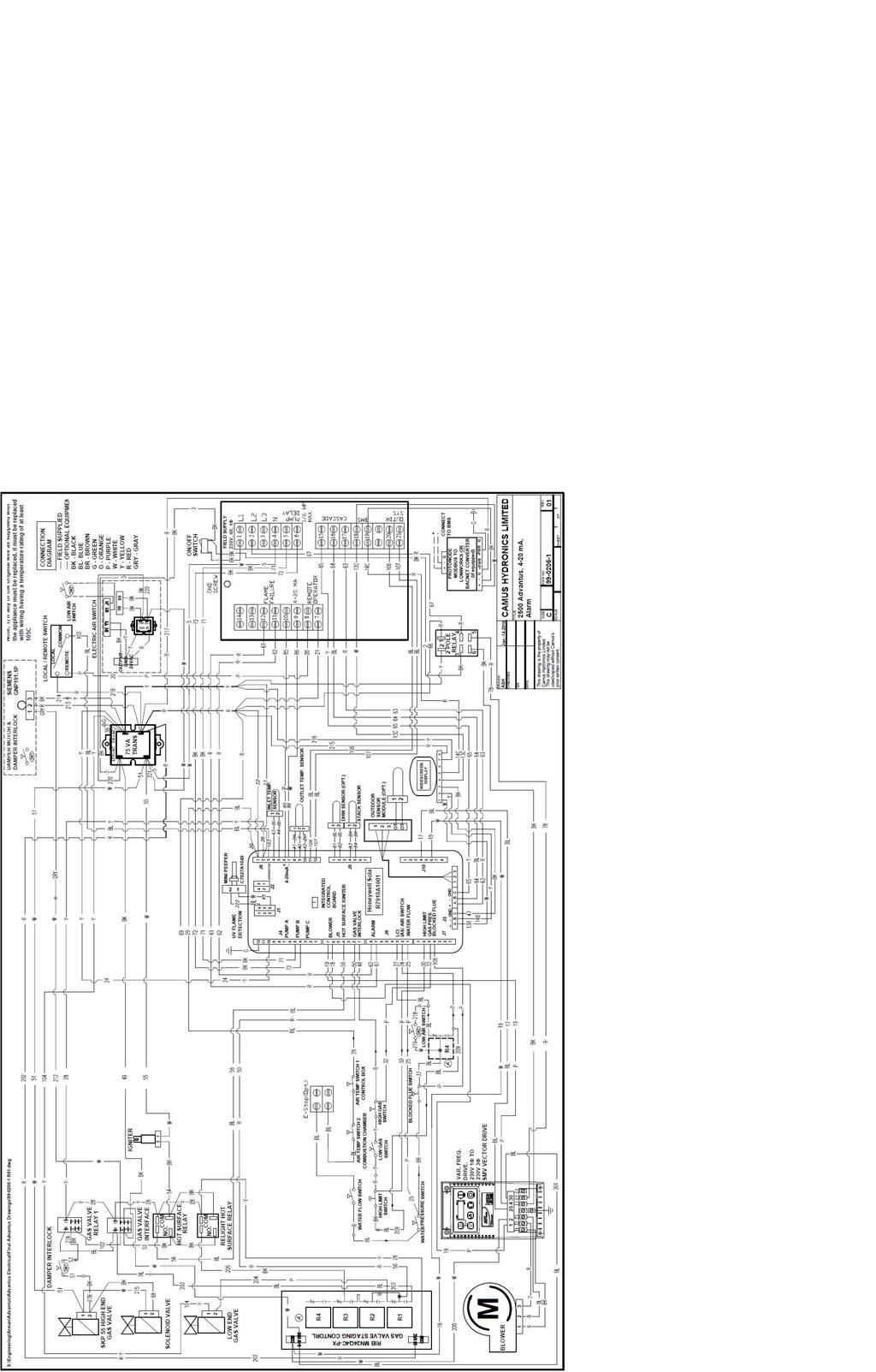
99 93
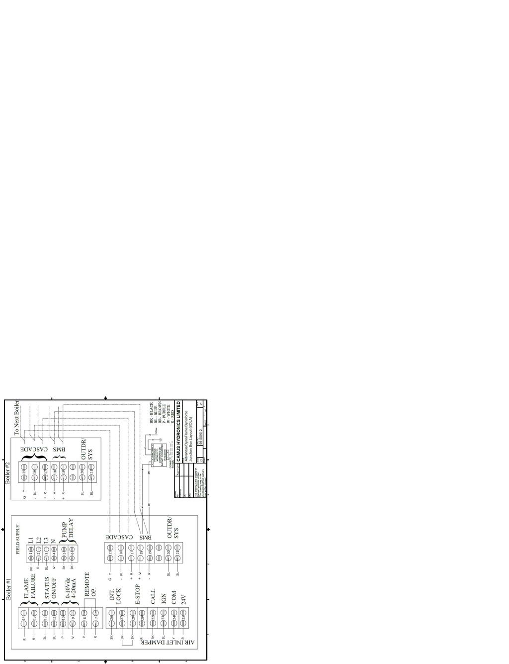
100 94
101 CONDENSING BOILER LIMITED WARRANTY GENERAL Camus Hydronics Limited ( Camus ) extends the following LIMITED WARRANTY to the owner of this appliance, provided that the product has been installed and operated in accordance with the Installation Manual provided with the equipment. Camus will furnish a replacement for, or at Camus option repair, any part that within the period specified below, shall fail in normal use and service at its original installation location due to any defect in workmanship, material or design. The repaired or replacement part will be warranted for only the unexpired portion of the original warranty. This Limited warranty does not cover failures or malfunctions resulting from: (1) Failure to properly install, operate or maintain the equipment in accordance with Camus manual; (2) Abuse, alteration, accident, fire, flood, foundation problems and the like; (3) Sediment or lime build-up, freezing, or other conditions causing inadequate water circulation; (4) Pitting and erosion caused by high water velocity; (5) Failure of connected systems devices, such as pump or controller; (6) Use of non-factory authorized accessories or other components in conjunction with the system; (7) failing to eliminate air from, or replenish water in, the connected water system; (8) Chemical contamination of combustion air or use of chemical additives to water; (9) Production of noise, odors, discoloration or rusty water; (10) Damage to surrounds or property caused by leakage or malfunction; (11) All labor costs associated with the replacement and/or repair of the unit; (12) Any failed component of the hydronic system not manufactured as part of the boiler. HEAT EXCHANGER Within 10 years of the appliance having declared FOB from Camus, a heat exchanger shall prove upon examination by Camus to be defective in material or workmanship, Camus will exchange or repair such part or portion if deemed warranty based on the number of years the appliance has been in service. Years In Years In Advantus Service Service Advantus 1 100% 6 100% 2 100% 7 100% 3 100% 8 100% 4 100% 9 100% 5 100% % The exchanged or repaired heat exchanger will carry the balance of the remaining original warranty provided with the appliance based on the FOB date. In the event a replacement heat exchanger is delivered and if the defective heat exchanger is deemed to be repairable by Camus the repaired heat exchanger will be returned to the customer and a credit will not be issued. Heat Exchanger shall be warranted for (20) years of the appliance having declared FOB from Camus against Thermal Shock (excluded, however, if caused by appliance operation at large changes exceeding 150ºF between the water temperature at inlet and appliance temperature or operating at temperatures exceeding 210 o F (AVH & AVW). BURNER If within FIVE years of the appliance having declared FOB from Camus to be defective in material or workmanship, Camus will exchange or repair such part or portion. ANY OTHER PART If any other part fails within one (1) year after installation, or eighteen (18) months of the appliance having declared FOB from Camus whichever comes first Camus will furnish a replacement or repair that part. Replacement parts will be shipped FOB our factory. DURATION OF LIMITED WARRANTY Any Limited warranty, including the warranty of merchantability imposed on the sale of the boiler under the laws of the state or province of sale are Limited in duration to one year from date of original installation. STATE LAW & LIMITED WARRANTY Some states or provinces do not allow: a) Limitations on how long an implied warranty lasts b) Limitations on incidental or consequential damages. The listed limitations may or may not apply to you. This warranty gives you specific legal rights, and you may also have other rights which may vary from state to state and province to province. CONDITIONS We will not: a) Repair or replace any boiler, or part, subject to conditions outlined in This Limited Warranty Does Not Cover b) Reimburse any costs associated with repair and/or replacement c) Replace and/or repair any boiler without complete model number/serial number d) Replace any boiler without prior receipt of actual rating plate from the appliance. HOW TO MAKE A CLAIM Any claim under this warranty shall be made directly to Camus Hydronics Limited Canadian Head Office SERVICE LABOR RESPONSIBILITY Camus shall not be responsible for any labor expenses to service, repair or replace the components supplied. Such costs are the responsibility of the owner. DISCLAIMERS Camus shall not be responsible for any water damage. Provisions should be made that in the event of a water/appliance or fitting leak, the resulting flow of water will not cause damage to its surroundings. Name of Owner: Name of Dealer: Address: Model Number: Serial Number: Date of Installation: Date of Initial Operation: Camus Hydronics Ltd., 6226 Netherhart Road, Mississauga, Ontario, L5T 1B7, CANADA 95


102 CAMUS Hydronics is a manufacturer of replacement parts for most copper finned and stainless steel water heaters and heating boilers as well as a supplier of specialty HVAC products. Our service line is open 24 hours, 7 days a week! The CAMUS CERTIFIED! Seal assures you that Reliability, Efficiency & Serviceability are built into every single unit! For more information on our innovative products from CAMUS Hydronics Limited, call today!
INSTALLATION OPERATION AND SERVICE MANUAL
 INSTALLATION OPERATION AND SERVICE MANUAL GAS FIRED COMMERCIAL CONDENSING STAINLESS STEEL TUBE BOILERS DynaForce SERIES HYDRONIC HEATING Models; DRH300, 350 400, 500, 600, 800, 1000, 1200, 1400, 1600,
INSTALLATION OPERATION AND SERVICE MANUAL
 INSTALLATION OPERATION AND SERVICE MANUAL GAS FIRED WALL HUNG & FLOOR MOUNT RESIDENTIAL COMMERCIAL STAINLESS STEEL BOILERS DynaMax HS SERIES HYDRONIC HEATING Models; DMH081, 101, 151, 201, 251, 211, 261,
INSTALLATION OPERATION AND SERVICE MANUAL ADVANTUS SERIES GAS FIRED FIRE TUBE COMMERCIAL CONDENSING STAINLESS STEEL BOILERS
 INSTALLATION OPERATION AND SERVICE MANUAL ADVANTUS SERIES GAS FIRED FIRE TUBE COMMERCIAL CONDENSING STAINLESS STEEL BOILERS HYDRONIC HEATING Models; AVH 500, 600, 800, 1000, 1200, 1400, 1600, 1800, 2000,
INSTALLATION OPERATION AND SERVICE MANUAL
 INSTALLATION OPERATION AND SERVICE MANUAL TH SERIES GAS FIRED RESIDENTIAL AND COMMERCIAL STAINLESS STEEL TANK HEATERS HOT WATER SUPPLY Models; TH082,102, 152, 202, 252, 292, 392, 502 H HLW WARNING: If
Power-Fin 4:1 HOT WATER HEATING BOILERS DOMESTIC HOT WATER SUPPLY BOILERS 1,500,000, 1,700,000 and 2,000,000 Btu/hr MODELS
 PBE/PFE-i&s-03 INSTALLATION AND SERVICE MANUAL Power-Fin 4:1 HOT WATER HEATING BOILERS DOMESTIC HOT WATER SUPPLY BOILERS 1,500,000, 1,700,000 and 2,000,000 Btu/hr MODELS FIG. 1 Front View 1,500,000-2,000,000
INSTALLATION OPERATION AND SERVICE MANUAL
 INSTALLATION OPERATION AND SERVICE MANUAL GAS FIRED COMMERCIAL COPPER TUBE AND STAINLESS STEEL BOILERS DynaFlame SERIES NON-CONDENSING Models; DFH/W500, 750, 1100, 1200, 1500, 1750, 2000, 2500, 3000, 3500,
INSTALLATION AND SERVICE MANUAL. Hot Water Heating Boilers Domestic Hot Water Supply Boilers 399, ,000 Btu/hr Models
 INSTALLATION AND SERVICE MANUAL CF/CH(P)i&S-02 Hot Water Heating Boilers Domestic Hot Water Supply Boilers 399,999 750,000 Btu/hr Models Installation and service must be performed by a qualified service
INSTALLATION AND SERVICE MANUAL
 INSTALLATION AND SERVICE MANUAL CHF2-i&s-02 Hot Water Heating Boilers Domestic Hot Water Supply Boilers 300,000 and 990,000 2,070,000 BTU Models Installation and service must be performed by a qualified
USER S INFORMATION MANUAL
 USER S INFORMATION MANUAL HOT WATER HEATING BOILERS DOMESTIC WATER HEATERS 150,000-300,000 Btu/hr MODELS EB-EWU-02 IMPORTANT INSTALLER - AFFIX INSTALLATION MANUAL ADJACENT TO THE BOILER CONSUMER - RETAIN
INSTALLATION AND SERVICE MANUAL
 INSTALLATION AND SERVICE MANUAL HOT WATER HEATING BOILERS Domestic Water Heaters 150,000-300,000 Btu/hr MODELS EB-EW-I-S-09 IMPORTANT: This is a gas appliance and should be installed by a licensed electrician
User s Information Manual Models: 45, ,000 Btu/hr
 SBR-USER_100161678_2000017137_Rev C User s Information Manual Models: 45,000-260,000 Btu/hr If the information in this manual is not followed exactly, a fire or explosion may result causing property damage,
Installation & Operation Manual Models: 502, 752, 1002, 1302, 1501, 1701, and 2001 Up To 5:1 Turndown
 PBX-PFX-I-O_100161632_2000016130_Rev M Installation & Operation Manual Models: 502, 752, 1002, 1302, 1501, 1701, and 2001 Up To 5:1 Turndown WARNING: This manual supplies information for the installation,
Vent Supplement Ultra-80, -105, -155, -230 & -310
 Gas-fired water boiler Vent Supplement Ultra-80, -105, -155, -230 & -310 Installation of: Vent piping Air piping with This document must only be used by a qualified heating installer/service technician.
Installation & Operation Manual Models: Up To 4:1 Turndown
 VFS-I-O_100161775_2000019057_Rev D Installation & Operation Manual Models: 500-2000 Up To 4:1 Turndown WARNING: This manual supplies information for the installation, operation, and servicing of the appliance.
User s Information Manual Models: ER152, ER202, ER252, ER302, and ER402
 ERP-USER_100161005_2000003726_Rev D User s Information Manual Models: ER152, ER202, ER252, ER302, and ER402 If the information in this manual is not followed exactly, a fire or explosion may result causing
User Manual Models: 502, 752, 1002, 1302, 1501, 1701, and 2001 Up To 5:1 Turndown
 PBX-PFX-USER Rev D User Manual Models: 502, 752, 1002, 1302, 1501, 1701, and 2001 Up To 5:1 Turndown If the information in this manual is not followed exactly, a fire or explosion may result causing property
Installation & Operation Manual Models: ER152, ER202, ER252, ER302, and ER402
 ERP-I-O-Rev G Installation & Operation Manual Models: ER152, ER202, ER252, ER302, and ER402 WARNING: This manual supplies information for the installation, operation, and servicing of the appliance. It
User s Information Manual Lynx Direct-Vent Sealed Combustion Condensing Boiler Model LX-90, LX-120, LX-150
 Residential Gas fired Hot Water Boilers User s Information Manual Lynx Direct-Vent Sealed Combustion Condensing Boiler Model LX-90, LX-120, LX-150 FOR YOUR SAFETY: Before operating this boiler, READ this
PVC, CPVC, PP & SS Vent Supplement
 PVC, CPVC, PP & SS Vent Supplement L I S T E D This document is intended to be used by a qualified heating contractor or service technician. Read all instructions within this document and within the PRESTIGE
TRIAD Boiler Systems, Inc Atlantic Drive, Unit 2 West Chicago, IL
 TRIIUMPH SERIIES AIIR SUPPLY AND VENTIING GUIIDE C.S.A Design-Certified Complies with ANSI Z21.13/CSA 4.9 Gas-Fired Low Pressure Steam & Hot Water Boilers ASME Code Section IV C.S.A Design-Certified Complies
Typical Specifications For: ADVANTUS TM DOMESTIC HOT WATER SUPPLY Models AV(W)0500 AV(W)4000
0500 AV(W)4000") s AV(W)0500 AV(W) The domestic hot water boiler shall be a Camus ADVANTUS TM model having a recovery capacity of gph (lph) at 100ºF (56ºC) for DHW The domestic hot water boiler shall be design certified
s AV(W)0500 AV(W) The domestic hot water boiler shall be a Camus ADVANTUS TM model having a recovery capacity of gph (lph) at 100ºF (56ºC) for DHW The domestic hot water boiler shall be design certified
User s Information Manual
 User s Information Manual Gas-Fired Storage Water Heater, Tankless Water Heater, Heating Appliance, and Combination Appliance Models IF THE INFORMATION IN THIS MANUAL IS NOT FOLLOWED EXACTLY, A FIRE OR
INSTALLATION AND SERVICE MANUAL
 INSTALLATION AND SERVICE MANUAL HORIZONTAL COMBUSTION AIR INLET KITS CATEGORY III VENTING FOR SEPARATED COMBUSTION TUBULAR GAS FIRED UNIT HEATERS USE 5 INCH KIT FOR UNITS WITH CAPACITIES 100,000 TO 250,000
INSTALLATION AND SERVICE MANUAL
 INSTALLATION AND SERVICE MANUAL VERTICAL COMBUSTION AIR INLET KITS CATEGORY III VENTING FOR SEPARATED COMBUSTION TUBULAR GAS FIRED UNIT HEATERS USE 5 INCH KIT FOR UNITS WITH CAPACITIES 100,000 TO 250,000
Commercial Water Heaters. Genesis. Water Heater Design Guide
 Commercial Water Heaters Genesis Water Heater Design Guide Dear Customer, This Genesis Water Heater Design Guide is intended to explain, simplify and help in the planning and the installation of our Genesis
User s Information Manual
 User s Information Manual Series 3 Models 550 and 750 MBH Commercial Condensing Gas-fired water boilers If the information in this manual is not followed exactly, a fire or explosion may result, causing
Typical Specifications For: ADVANTUS TM DOMESTIC HOT WATER SUPPLY Models AV(W)0500 AV(W)4000
0500 AV(W)4000") s AV(W)0500 AV(W) The domestic hot water boiler shall be a Camus ADVANTUS TM model having a recovery capacity of gph (lph) at 100ºF (56ºC) for DHW The domestic hot water boiler shall be design certified
s AV(W)0500 AV(W) The domestic hot water boiler shall be a Camus ADVANTUS TM model having a recovery capacity of gph (lph) at 100ºF (56ºC) for DHW The domestic hot water boiler shall be design certified
Residential Gas Hybrid Water Heater
 Residential Gas Hybrid Water Heater USER S INFORMATION MANUAL WGRGH20NG75F / WGRGH20NG76F / WGRGH20NG100F WGRGHNG75F / WGRGHNG76F / WGRGHNG100F Models* *A suffix of LP denotes propane gas NOTICE: Westinghouse
Direct Exhaust Venting Kit Instructions
 CONDENSING GAS BOILER 220/299/300/399 Direct Exhaust Venting Kit Instructions Evergreen 220/299/300/399 Kit part number 383-500-769 STOP! Read before proceeding Hazard definitions The following defined
Direct Vent System Required
 CB-200A Cottage Base Installation Instructions IMPORTANT: Read all instructions carefully before beginning the installation. This base must be installed by a qualified installing agency and in accordance
Installation & Operation Manual Models:
 CPX-I-O_100160928_2000001946_Rev R Installation & Operation Manual Models: 502-2072 WARNING: If the information in these instructions is not followed exactly, a fire or explosion may result causing property
Universal Fire Tube Boiler Wall Mount Models
 Universal Fire Tube Boiler Wall Mount Models USER S INFORMATION MANUAL Models WBRU**80W / 100W / 120W / 140W / 175W / 199W **NG denotes Natural Gas Model, LP Denotes Propane Model Heat Exchanger Bears
User s Information Manual
 Gas-fired Water boiler Series 2 NOTICE: Series 1/Series 2 identification Read the boiler rating plate to determine the series number. The rating plate is located on the right side of the boiler. User s
ProLine XE Combi Boiler
 100298581_2000552611_Rev A ProLine XE ProLine XE User Manual Models: 110-150 - 199 If the information in this manual is not followed exactly, a fire or explosion may result causing property damage, personal
CAMUS. two-pass counter flow fire tube commercial boilers. for hydronic heating and hot water supply TURNDOWN RATIO! HYDRONICS LTD. Rev.
 UP TO 25:1 TURNDOWN RATIO! CAMUS ADVANTUS HYDRONICS LTD. for hydronic heating and hot water supply two-pass counter flow fire tube commercial boilers Rev.03 Rev.00 FEATURES & CONTROLS get connected In
Elite. User s Information Manual. Elite and Elite VWH* All Models
 Elite User s Information Manual Elite and Elite VWH* All Models Heat Exchanger Bears the ASME H Stamp IF THE INFORMATION IN THIS MANUAL IS NOT FOLLOWED EXACTLY, A FIRE OR EXPLOSION MAY RESULT, CAUSING
Gas Fired Residential Combi Boiler Floor and Wall Mount Models
 Gas Fired Residential Combi Boiler Floor and Wall Mount Models USER S INFORMATION MANUAL Models WBRC**140W WBRC**199W WBRC**140F WBRC**199F ** NG Refers to Natural Gas Operation LP Refers to Propane Gas
User s Information Manual
 User s Information Manual Series 2 Models 1000-2000 MBH Commercial Condensing Gas-fired water boilers If the information in this manual is not followed exactly, a fire or explosion may result, causing
POWER VENTER. Model: PVE Series
 POWER VENTER Model: PVE Series CONTENTS Typical Venting System Components... System Operation... Power Venter Sizing... Installation Safety Instructions... Installation of Power Venter... Connecting Power
User s Information Manual
 User s Information Manual CONDENSING GAS BOILER 220/299/300/399 If the information in this manual is not followed exactly, a fire or explosion may result, causing property damage, personal injury or loss
Internet Version for Reference Only INDUCED DRAFT COMMERCIAL WATER HEATERS SUPPLEMENT INSTRUCTIONS TO PART #
 INDUCED DRAFT COMMERCIAL WATER HEATERS SUPPLEMENT INSTRUCTIONS TO PART #238-39387-00 THIS INSTRUCTION SUPPLEMENT IS ONLY INTENDED TO GIVE INSTALLATION INSTRUCTIONS AND INFORMATION RELATED TO THE INDUCED
EL195UHE SERIES GAS FURNACE WARNING WARNING
 2012 Lennox Industries Inc. Dallas, Texas, USA 506737-01 12/2012 Supersedes 06/2011 EL195UHE SERIES GAS FURNACE Improper installation, adjustment, alteration, service or maintenance can cause property
P.O. Box , Dallas, TX USER'S INFORMATION MANUAL Single-Stage Warm Air Gas Furnaces
 P.O. Box 799900, Dallas, TX 75379-9900 USER'S INFORMATION MANUAL Single-Stage Warm Air Gas Furnaces This is a safety alert symbol and should never be ignored. When you see this symbol on labels or in manuals,
Do not use this vent pipe or fittings for venting incinerators of any kind.
 ! CAUTION! Do not use this vent pipe or fittings for venting incinerators of any kind. C.S.A. Certified For Natural Gas Or Propane Tested For 100 LBS. ASME Working Pressure For correct installation of
Installation & Operation Manual Models:
 AWII-I-O Rev G Installation & Operation Manual Models: 151-801 : If the information in this manual is not followed exactly, a fire or explosion may result causing property damage, personal injury or loss
XTHERM, TYPE WH - MODELS 1005A- 2005A DIVISION COMMERCIAL, WATER-TUBE, CONDENSING GAS DOMESTIC WATER HEATERS
 XTHERM, TYPE WH - MODELS 1005A- 2005A Catalog No.: 3500.801 Effective: 11-15-14 Replaces: NEW PART 1 - GENERAL 1.1 SUMMARY DIVISION 23 34 36.29 COMMERCIAL, WATER-TUBE, CONDENSING GAS DOMESTIC WATER HEATERS
ASX7-4-IOM-6 J
 INSTALLATION INSTRUCTIONS 4" COMBUSTION AIR INLET KIT TUBULAR GAS FIRED DIRECT SPARK PROPELLER UNIT HEATERS UNIT CONVERSION & CATEGORY III VENTING FOR SEPARATED COMBUSTION For 30,000 to 75,000 BTU/HR SUPPLEMENT
ML180UH SERIES GAS FURNACE WARNING WARNING
 2017 Lennox Industries Inc. Dallas, Texas, USA 506525-01 04/2017 Supersedes 10/2015 ML180UH SERIES GAS FURNACE Improper installation, adjustment, alteration, service or maintenance can cause property damage,
EL296UHV SERIES GAS FURNACE WARNING WARNING
 2011 Lennox Industries Inc. Dallas, Texas, USA 506769 01 08/2012 Supersedes 10/2011 EL296UHV SERIES GAS FURNACE Improper installation, adjustment, alteration, service or maintenance can cause property
INSTALLATION OPERATION AND SERVICE MANUAL MICOFLAME SERIES 2
 INSTALLATION OPERATION AND SERVICE MANUAL MICOFLAME SERIES 2 GAS FIRED COMMERCIAL COPPER TUBE BOILERS FOR HYDRONIC HEATING Models; MFH800, 1000, 1200, 1400, 1600, 1800, 2000 HOT WATER SUPPLY Models; MFW800,
User s Information Manual
 TM User s Information Manual Commercial Condensing Gas-fired water boilers If the information in this manual is not followed exactly, a fire or explosion may result, causing property damage, personal injury
Boiler Manual Installation and Operation Instructions
 XLF-I0M-10 82-0317 Finned Copper Tube Gas Boilers (MB) & Water Heaters (MW) Boiler Manual Installation and Operation Instructions Also read and follow: HeatNet Control Manual This manual is intended only
ZG Shown READ ALL INSTRUCTIONS IN THIS MANUAL AND RETAIN FOR FUTURE REFERENCE WARNING
 See unit nameplate for manufacturer and address. 507258-04 7/2018 Supersedes 10/2017 ZG 036, 048, 060, 072, 074 (3, 4, 5 and 6 Tons) ZG 092, 102, 120, 150 (7-1/2, 8-1/2, 10 and 12 Tons) ROOFTOP UNITS ZG
GWS. Venting Manual. Gas-Fired Water Boilers. Hazard definitions. Contents. Venting method definitions
 GWS Gas-Fired Water Boilers Venting Manual Hazard definitions Contents Page Hazards that will cause severe personal injury, death or substantial property damage. Hazards that can cause severe personal
Installation & Operation Manual Models:
 CFX-CHX-I-O_100161845_2000001375_Rev L Installation & Operation Manual Models: 402-2072 WARNING: If the information in these instructions is not followed exactly, a fire or explosion may result causing
USER S INFORMATION MANUAL
 2017 Lennox Industries Inc. Dallas, Texas, USA 506737-01 04/2017 Supersedes 03/2017 USER S INFORMATION MANUAL EL195UHE SERIES GAS FURNACE Improper installation, adjustment, alteration, service or maintenance
SLP98UH SERIES VARIABLE CAPACITY GAS FURNACE WARNING WARNING
 2015 Lennox Industries Inc. Dallas, Texas, USA 506443-01 01/2015 Supersedes 08/2012 SLP98UH SERIES VARIABLE CAPACITY GAS FURNACE Improper installation, adjustment, alteration, service or maintenance can
EL195DFE SERIES GAS FURNACE WARNING
 2011 Lennox Industries Inc. Dallas, Texas, USA 506739 01 06/2011 EL195DFE SERIES GAS FURNACE Litho U.S.A. FIRE OR EXPLOSION HAZARD. Failure to follow safety warnings exactly could result in serious injury,
INSTALLATION OPERATION AND SERVICE MANUAL
 INSTALLATION OPERATION AND SERVICE MANUAL MODULATING MICOFLAME SERIES GAS FIRED RESIDENTIAL AND COMMERCIAL COPPER TUBE BOILERS FOR HYDRONIC HEATING Non-Condensing Models; MFH400, 500, 600 Condensing Models;
ASX7-5-IOM-3 J
 INSTALLATION INSTRUCTIONS 5" CONCENTRIC VENT TERMINAL KIT TUBULAR GAS FIRED DIRECT SPARK PROPELLER UNIT HEATERS UNIT CONVERSION & CATEGORY III VENTING FOR SEPARATED COMBUSTION For 90,000 to 120,000 BTU/HR
PVE SERIES POWER VENTER SYSTEM MANUAL
 PVE SERIES POWER VENTER SYSTEM MANUAL Contents Page I. Typical Venting System Components 2 II. System Operation 3 III. Power Venter Sizing 3,4 IV. Installation Safety Instructions 5,6 V. Installation of
User s Information Manual Models:
 FB-USER Rev C User s Information Manual Models:1.5-5.0 WARNING: If the information in these instructions is not followed exactly, a fire or explosion may result causing property damage, personal injury
GOLD. Venting Supplement. Water Boiler Series 3 & 4. for 3" venting
 GOLD GV Water Boiler Series 3 & 4 Venting Supplement for 3" venting Special gas vent system vent and combustion air supplement for 3" diameter venting. The following manufacturers AL29-4C Stainless Steel
Aqua Balance. User s Information Manual. WMB-155C Wall Mount Gas-Fired Combination Boiler Heating and Domestic Hot Water
 Aqua Balance WMB-155C Wall Mount Gas-Fired Combination Boiler Heating and Domestic Hot Water User s Information Manual * Low Lead Content If the information in this manual is not followed exactly, a fire
Venting Supplement Saf-T Vent 3" venting Special gas vent system vent and combustion air supplement for 3" diameter venting Hazard definitions
 GOLD GV Water Boiler Series 3 & 4 Venting Supplement 3" venting Special gas vent system vent and combustion air supplement for 3" diameter venting Heat-Fab, Inc. AL29-4C Stainless Steel Special Gas Vent
Tankless Water Heater
 Tankless Water Heater USER S INFORMATION MANUAL Models WGRT**150 / WGRT**199 / WGRTC**199 **A suffix of LP denotes propane gas **A suffix of NG denotes natural gas NOTICE: Westinghouse reserves the right
POWER VENTER SYSTEM. Model: PVO-300, PVO-600
 POWER VENTER SYSTEM Model: PVO-300, PVO-600 Included is one ETL and cetl listed Power Venter to be used primarily with a single 120VAC controlled oil fired furnace, boiler, or water heater. The PVO may
INSTALLATION OPERATION AND SERVICE MANUAL
 INSTALLATION OPERATION AND SERVICE MANUAL MICOFLAME SERIES 2 GAS FIRED COMMERCIAL COPPER TUBE BOILERS FOR HYDRONIC HEATING Models; MFH800, 1000, 1200, 1400, 1600, 1800, 2000 HOT WATER SUPPLY Models; MFW800,
User s Information Manual
 User s Information Manual Gas-fired water boilers Series 4 Featuring Flexibility Series 4 If the information in this manual is not followed exactly, a fire or explosion may result, causing property damage,
EL195UH SERIES GAS FURNACE WARNING
 2010 Lennox Industries Inc. Dallas, Texas, USA 506597 01 11/2010 EL195UH SERIES GAS FURNACE Litho U.S.A. FIRE OR EXPLOSION HAZARD. Failure to follow safety warnings exactly could result in serious injury,
GOLD GV. Venting Supplement. Water boiler Series 3. Special gas vent system vent and combustion air supplement. Hazard definitions.
 GOLD GV Water boiler Series 3 Venting Supplement Special gas vent system vent and combustion air supplement ProTech Systems AL29-4C Stainless Steel Special Gas Vent System may be used in new installations
GOLD GV. Venting Supplement for 3 venting. Water Boiler Series 3 & 4
 GOLD GV Water Boiler Series 3 & 4 Venting Supplement for 3 venting Special gas vent system vent and combustion air supplement for 3 diameter venting. The following manufacturers AL29-4C Stainless Steel
DESIGNER S GUIDE COPPER-FIN
 DESIGNER S GUIDE COPPER-FIN BOILER 495,000 2,065,000 Btu/hr Dear Specifier/Project Manager, At Lochinvar, we have long recognized the importance of innovation to any product or service. Those who enter
SAMPLE SPECIFICATION FOR RIELLO ARRAY MODULATING BOILER
 SAMPLE SPECIFICATION FOR RIELLO ARRAY MODULATING BOILER PART 1 GENERAL 1.01 RELATED DOCUMENTS A. ANSI Z21.13 American National Standard for Gas-Fired Low Pressure Steam and Hot Water Boilers B. ASME Section
Boiler Manual. Finned Copper Tube Gas Boilers (MB) & Water Heaters (MW) Installation and Operation Instructions. HeatNet Control Manual
 & Water Heaters (MW) Installation and Operation Instructions. HeatNet Control Manual") XLF-I0M-6 82-0317 Finned Copper Tube Gas Boilers (MB) & Water Heaters (MW) Boiler Manual Installation and Operation Instructions Also read and follow: HeatNet Control Manual This manual is intended only
XLF-I0M-6 82-0317 Finned Copper Tube Gas Boilers (MB) & Water Heaters (MW) Boiler Manual Installation and Operation Instructions Also read and follow: HeatNet Control Manual This manual is intended only
Introduction Engineering and Design Manual
 Genesis Engineering and Design Manual Introduction Engineering and Design Manual Dear A. O. Smith Customer, This Engineering and Design Manual has been written to aid in designing and specifying A. O.
WARNING FIRE OR EXPLOSION HAZARD.
 2017 Lennox Industries Inc. Dallas, Texas, USA 506897-01 04/2017 Supersedes 10/2015 EL280DF SERIES GAS FURNACE Improper installation, adjustment, alteration, service or maintenance can cause property damage,
MC Series Gas-Fired Heating Appliance
 MC Series Gas-Fired Heating Appliance USER S INFORMATION MANUAL MC Series Models MC50 / MC80 MC99 / MC120 NOTICE: HTP reserves the right to make product changes or updates without notice and will not be
DIVISION COMMERCIAL, GRID-TYPE, FINNED-TUBE, GAS DOMESTIC WATER HEATERS
 MVB, TYPE WH - MODELS 503A-2003A SUGGESTED SPECIFICATIONS Catalog No.: 3500.952C Effective: 06-25-15 Replaces: 12-22-09 DIVISION 23 34 36.29 COMMERCIAL, GRID-TYPE, FINNED-TUBE, GAS DOMESTIC WATER HEATERS
Installing, Operating & Maintaining MUNCHKIN VWH HIGH EFFICIENCY HOT WATER SUPPLY BOILER
 Installing, Operating & Maintaining MUNCHKIN VWH HIGH EFFICIENCY HOT WATER SUPPLY BOILER WARNING If the information in this manual is not followed exactly, a fire or explosion may result causing property
USER S INFORMATION MANUAL Model: HSE 125 N/P, HSE 145 N/P Gas-fired, Condensing Boiler and Instantaneous Water Heater
 USER S INFORMATION MANUAL Model: HSE 125 N/P, HSE 145 N/P Gas-fired, Condensing Boiler and Instantaneous Water Heater Contents Section Page Major Components... 2 1 About Our Manual... 2 2 Refractory Handling...
G61MPV SERIES GAS FURNACE WARNING
 2003 Lennox Industries Inc. Dallas, Texas, USA 504,809M 03/2009 Supersedes 06/2003 G61MPV SERIES GAS FURNACE Litho U.S.A. FIRE OR EXPLOSION HAZARD. Failure to follow safety warnings exactly could result
Noble Fire Tube Boiler and Combi Installation & Service Manual NKC NKB
 100275091_2000533998_Rev R FIRE TUBE Noble Fire Tube Boiler and Combi NKC 110-199 NKB 80-150 This manual must only be used by a qualified heating installer / service technician. Read all instructions in
INSTALLATION INSTRUCTIONS
 INSTALLATION INSTRUCTIONS G1D91BT, CG90TB, & G1D93BT High Efficiency 90+ Condensing Gas Furnace WARNING Improper installation, adjustment, alteration, service, or maintenance can cause injury or property
GOLD. User s Information Manual. Water Boiler Series 4
 GV Water Boiler Series 4 User s Information Manual If the information in this manual is not followed exactly, a fire or explosion may result, causing property damage, personal injury or loss of life. Do
HIGH-EFFICIENCY UPFLOW FURNACE INSTALLER'S INFORMATION MANUAL
 HIGH-EFFICIENCY UPFLOW FURNACE INSTALLER'S INFORMATION MANUAL Model Numbers WMVSA054NH3R WMVSA072NH3R, WMVSA072NH4R WMVSA090NH3R, WMVSA090NH4R WMVSA108NH5R DESIGN WMVSA126NH5R C E R TI F I ED ATTENTION,
WATER-TUBE POOL HEATERS
 XTHERM, TYPE P - MODELS 1005A-2005A SUGGESTED SPECIFICATIONS Catalog No.: 6000.63B Effective: 3-01-15 Replaces: 9-01-09 WATER-TUBE POOL HEATERS PART 1 - GENERAL 1.1 SUMMARY A. Section includes condensing,
If the information in this manual is not followed exactly, a fire or explosion may result causing property damage, personal injury or loss of life.
 prestige User s Information Manual If the information in this manual is not followed exactly, a fire or explosion may result causing property damage, personal injury or loss of life. FOR YOUR SAFETY Do
DIVISION FINNED WATER-TUBE BOILERS
 MVB, TYPE H - MODELS 504A-2004A SUGGESTED SPECIFICATIONS Catalog No.: 2000.933C Effective: 06-25-15 Replaces: 12-21-09 DIVISION 23 52 33.13 FINNED WATER-TUBE BOILERS PART 1 - GENERAL 1.1 SUMMARY A. Section
DIVISION FINNED WATER-TUBE BOILERS
 MVB, TYPE H - MODELS 2503-4003 SUGGESTED SPECIFICATIONS Catalog No.: 2000.934A Effective: 04-01-14 Replaces: 06-01-13 DIVISION 23 52 33.13 FINNED WATER-TUBE BOILERS PART 1 - GENERAL 1.1 SUMMARY A. Section
INSTALLATION INSTRUCTIONS G2D93CT, G2D93CU, G2D95CT, & G2D95CU High Efficiency Multiposition Gas Furnace with System Sentry Control System WARNING
 INSTALLATION INSTRUCTIONS G2D93CT, G2D93CU, G2D95CT, & G2D95CU High Efficiency Multiposition Gas Furnace with System Sentry Control System Save these instructions for future reference WARNING Improper
Trinity Lx400 High Efficiency Gas Condensing Boiler & Water Heater
 Part I - General Part II - Product Part III - Installation Project Name: Location: Engineer: Contractor: I. GENERAL Rep: Date: A. Supply and install modulating and condensing boiler(s)/water heater(s)
FINNED WATER-TUBE POOL HEATERS
 HI DELTA, TYPE P - MODELS 502C-902C SUGGESTED SPECIFICATIONS Catalog No.: 6000.601A Effective: 07-12-18 Replaces: 10-31-16 FINNED WATER-TUBE POOL HEATERS - GENERAL 1.1 SUMMARY A. Section includes gas-fired,
WATER-TUBE POOL HEATERS
 XTHERM, TYPE P - MODELS 2505-4005 SUGGESTED SPECIFICATIONS Catalog No.: 6000.70 Effective: 09-15-16 Replaces: NEW WATER-TUBE POOL HEATERS - GENERAL 1.1 SUMMARY A. Section includes condensing, gas-fired
User s Information Manual Models:
 FB-USER_100161014_2000004599 Rev F User s Information Manual Models: 2500-6000 WARNING: If the information in these instructions is not followed exactly, a fire or explosion may result causing property
USER S INFORMATION MANUAL
 USER S INFORMATION MANUAL UPFLOW/HORIZONTAL & DOWNFLOW TWO STAGE INDUCED DRAFT GAS FURNACES Recognize this symbol as an indication of Important Safety Information If the information in this manual is not
Mod Con INSTALLATION START-UP MAINTENANCE PARTS. Mod Con Models 300 / 500 / 850 LP / HL / LPHL
 Mod Con INSTALLATION START-UP MAINTENANCE PARTS Mod Con Models 300 / 500 / 850 LP / HL / LPHL This manual must only be used by a qualified heating installer/service technician. Read all instructions in
Contents. Hazard definitions
 GWS-090E Gas-Fired Water Boiler Boiler Manual Contents Page 1 Prepare boiler location...2 2 Prepare boiler...8 3 Install water piping...9 4 Venting and combustion air...12 5 Gas piping...12 6 Field wiring...13
Suggested Specifications Prestige Excellence 110
 Suggested Specifications Prestige Excellence 110 General Requirements A. Furnish and install (qty) completely assembled, modulating, sealed combustion, high efficiency, combination gas-fired boiler(s)
INSTALLATION AND OPERATING INSTRUCTIONS TABLE OF CONTENTS IMPORTANT
 C US This manual must be left with owner and should be hung on or adjacent to the boilerfor reference. COMMON VENTING MODELS CHS-300 through CHS-399 INSTALLATION AND OPERATING INSTRUCTIONS TABLE OF CONTENTS