Z-VENT MODEL SVE SERIES III INSTALLATION AND MAINTENANCE INSTRUCTIONS
|
|
|
- Reynard Crawford
- 5 years ago
- Views:
Transcription

1 Z-VENT MODEL SVE SERIES III INSTALLATION AND MAINTENANCE INSTRUCTIONS 3 & 4 SPECIAL STAINLESS STEEL VENTING SYSTEM FOR GAS BURNING APPLIANCES CATEGORY I, II, III, & IV TESTED AND LISTED BY UNDERWRITERS LABORATORIES INC. UL 1738 & ULC S Note the following before installation of Z-Vent installation. Examine all shipping components for possible shipping damage prior to supported. The Z-Vent system must be free to expand and contract. Pipe must be properly written. Proper joint assembly is essential for a safe installation. Follow these instructions exactly as assembly. Check severeness of joints upon completion of penetrations. Check for unrestricted vent movement through walls, ceilings and roof Different manufacturers have different joint systems and adhesives. Do Not Mix Pipe, Fittings or adaptor. Joining methods from different manufacturers beyond the flue collar FLEXMASTER CANADA LTD 452 ATTWELL DR. M9W 5C3 ETOBICOKE, ONTARIO (416) Z-FLEX US, INC. 20 COMMERCE PARK, NORTH BEDFORD, N.H (800)
2 Visit our web site at SPECIAL STAINLESS STEEL VENTING For use with Category I, II, III, IV appliances Contact Local Building or Fire Officials about Restrictions and Installation Inspections in your area as well as National codes: USA - National Fuel Gas Code ANSI-Z223.1/NFPA 54, CANADA -CAN\CGA-B149.1 or.2 Fuel Burning Installation Code Please refer to appliance manufacturers' instructions to determine proper sizing and connection of venting system to appliance, including maximum horizontal length, maximum height, and installation clearances (air spaces). The proper operation of the vent system and appliance requires parts specified by Z-FLEX with no deletions or substitutions. Z-FLEX recommends that an experienced professional who works with venting systems on a regular basis perform the installation. These instructions are intended as a guide to assist a professional installer. When the Z-VENT system is installed, the following should be observed: 1. A venting system that exits the structure through a sidewall or the like, shall terminate not less than 12 inches (254 mm) above the ground (see illustration # 2, page 5). 2. The termination of a system shall be located above the snow line in geographical areas where snow accumulates. The termination area should be kept clear of snow and ice at all times (see illustration # 2, page 5). 3. The vent shall not terminate less than 7 ft. (2.13 m) above a paved sidewalk or driveway. 4. The termination shall be 6 ft. (1.8 m) or more from the combustion air intake of any appliance. 5. The system shall terminate more than 3 ft. (.91 m) from any other building opening, gas utility meter, service regulator or the like. 6. Exterior mounted venting systems should be enclosed below the roof line with a chase to limit condensation and protect against mechanical failure. Vent system must be pitched minimum ¼ per foot back to condensate drain within the system. NOTES: A. The Z-FLEX SPECIAL STAINLESS VENT SYSTEM is for use only with appliances having a positive vent pressure of 8 of water column or less. B. Except for installation in one and two family dwellings, a venting system that extends through any zone above that on which the connected appliance is located shall be provided with an enclosure having a fire resistance rating equal to or greater than that of the floor or roof assemblies through which it passes. C. Do not place any type of insulation in any required air spaces surrounding the venting system. D. A termination must be used on all installations to assure proper operation and to prevent debris from entering the venting system. E. Vertical runs must use a fire-stop as a lateral support at each ceiling level and at least one support at the base of the vertical run where required by the appliance manufacturer. For vertical runs exceeding 16 ft (4.88m), a support collar is required at 16 ft (4.88m) intervals. Support horizontal runs using loose fitting metal straps as hangers and similar supports at each elbow. F: It may be required to have more than one condensate drain on a single vent system. Therefore it is recommended that vertical and horizontal drain tees with 3inch p-traps be installed on long vent systems in order to eliminate the system of condensate as quickly as possible. Note: These Drain Tees & Traps must be accessible for future inspections. 2


3 JOINT PROCEDURE (see illustration #1 and images 1, 2 & 3 below) The female end of each Z-Vent III component incorporates a silicone sealing gasket. Examine all components to insure that gasket integrity has remained during shipping. Gaskets must be in the proper position or flue gases could leak resulting in carbon monoxide poisoning. 1. Align pipes and push them together as far as they will go (to indent or at least 1.75 inches). 2. Tighten gear clamp to a minimum torque of 40 in/lbs. and a maximum of 50 in/lbs. Over tightening will cause seal to fail. DO NOT use power tools when tightening gear clamps 3. Proper pipe orientation is essential to achieve effective condensate flow. In most cases the use of a flue collar adaptor is required to connect directly to the appliance. This adaptor will configure the vent orientation with the gasket end of pipe and fittings towards termination. NOTE: Some flue collars may require the use of high temperature silicone sealant to make a positive pressure gas tight seal. DANGER Drilling holes in the vent components is NOT permitted. IMAGES 1, 2, & 3 CLEARANCE TO COMBUSTIBLES SYSTEM OPERATING TEMPERATURE CLEARANCE ENCLOSED CLEARANCE UNENCLOSED HORIZONTAL VERTICAL HORIZONTAL VERTICAL 300 F (149 C) 8 (200 mm) 4 (100 mm) 1 (25 mm) 1 (25 mm) 480 F (249 C) 8 (200 mm) 4 (100 mm) 1 (25 mm) 1 (25 mm) SIDE WALL VENTING INSTALLATION (see illustration #2 and images 4 & 5 below) 1. Penetrating a combustible wall requires the use of a wall thimble. The pipe may be mortared in directly without using a wall thimble, if the wall is non-combustible. Install wall thimble into wall, observing the aforementioned rules and/or local building codes. Select the point of wall penetration where the minimum ¼ per foot of slope (6.4 mm per 305 mm) can be maintained. A framed opening is required to insert the thimble halves. The thimble is adjustable for different wall thicknesses. Caulk around outside edge of plates as necessary and fasten to wall using suitable screws or nails. The vent pipe must be sealed at wall thimble as per code regarding continuous vapor barrier. 3
 must be installed around the pipe on the inside of wall to trap pipe in position so that the system cannot be moved in or out of wall (see images 4 & 5).")
 and joints (every forty-eight inches or less) using straps around pipes maintaining")

 not less than 1/4 (6.")
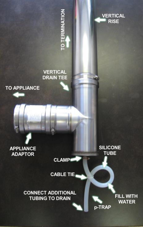
4 2. The system can now be assembled through the thimble (attach the termination first - note UP arrow) and then back to the appliance as per illustration using JOINT PROCEDURE as described on page #3. A gear clamp (or locking band) must be installed around the pipe on the inside of wall to trap pipe in position so that the system cannot be moved in or out of wall (see images 4 & 5). This applies to both combustible and non-combustible walls IMAGES 4 & 5 3. The system must be supported along its horizontal length at all elbow locations (see illustration 2 below) and joints (every forty-eight inches or less) using straps around pipes maintaining clearance to combustibles as per table on page The horizontal distance of the system from the appliance flue collar to the outside of the horizontal termination cannot be greater or less than that specified in the appliance manufacturer s installation instructions. Any horizontally installed portion of a venting system shall have a slope (upwards for Category II, III, or IV appliances or downwards for Category III or IV appliances) not less than 1/4 (6.4 mm) every 12 inches (305 mm) to prevent collection of condensate at any location in the assembly. Fasteners must not penetrate the components of the system either when joining pipes and fittings or using support straps. Drilling holes in the vent components is not permitted. The lengths of pipe may be cut on non-expanded end using aviation snips or a hacksaw (24 tpi). Make certain to keep the cut end cylindrical. The cut end must be filed or sanded smooth before joining (see images 6 & 7). i) Measure 2 inches from cut end and draw a line to indicate depth insertion. ii) Insert male end into female end to within ¼ inch of the drawn line to achieve full depth insertion. IMAGES 6 & 7 When installing the condensate tube be sure to form a trap by means of a 3 inch (76.2 mm) loop filled with water. This tube must be 3/8 inch ID high temperature silicone for at least the first 6 inches (152 mm) and attached with a gear clamp or hose clamp (see image 8 & 9). The effluent must be disposed of according to local regulations. NOTE: Z-FLEX recommends using a neutralizer kit when using a condensate trap. A condensate pump may be required. 4

5 IMAGE 8 IMAGE 9 ILLUSTRATION 2 5
6 VERTICAL VENTING (see illustrations #3 & 4) NOTE: The vent termination above the roof line shall consist of a continuous section of vent pipe only (without any joints) and must be at least 3 ft. (1 m) to a maximum of 6ft. above the roof line and 2 ft. (.61 m) higher than any part of a structure within 10 ft. (3.1 m). The total vertical distance of the vent system from appliance flue collar to the rain cap termination and the maximum length of offsets shall not exceed that specified in the appliance manufacturer s installation instructions. No continuous vertical run shall be longer than sixty feet (18.3 m). All horizontal sections must observe the rules for HORIZONTAL VENTING. The clearance to combustibles inside a chase shall be no less than 4 (100 mm). 1. Prior to beginning the installation loosely assemble all parts required to make sure all parts are present. 2. Locate position for venting system and proceed to cut holes for firestop support and firestop spacers. All vertical installations require the use of a support. Frame the opening of the floor using lumber, which is dimensionally consistent with the structural members. Insert the support from beneath the framed opening and secure with nails or screws as required. 3. Refer to JOINT PROCEDURE (illustration #1 & images 1, 2 &3) before assembling system. 4. Install system joining pipe as required up through roof (illustration #3). Tighten gear clamp on firestop support to hold vent system. NOTE: A firestop must be provided when a vent passes through a combustible floor or ceiling. The opening must be framed for the support since the support also serves as a firestop. 5. The roof flashing can now be installed. Where the vent passes through the roof a flashing must be used to maintain the required clearances and to protect from the elements. The framed opening must be large enough to provide the necessary clearances to combustibles, taking into account the slope of the roof. The flashing can be used on slopes from flat to 6/12 pitch. Install the flashing while holding the pipe centered in the opening. Fasten the flashing to the roof under the roofing material upslope from the pipe and above the roofing material below the pipe. Seal as required using high temperature silicone. 6. Install Top Support around pipe and against flashing collar and seal using high temperature silicone. (see illustration #3, 4, 5 & 6) 7. Attach rain cap using. JOINT PROCEDURE (illustration #1 & images 1, 2, & 3) 8. The vertical section is connected by an elbow joined to the horizontal run and then through a drain tee (see page 9 for details) to the appliance. Elbows are joined to pipe using the JOINT PROCEDURE (see illustration #1 & images 1, 2 & 3). NOTE: If there is no solid anchor point in the system below the roof (ie Firestop Support etc.) then a Z-Vent Guy Band must be used below the roof as follows. (see illustration #6) a. Attach the Guy Band at any point above an elbow or tee in the vertical section within 20 feet of the roof. b. Fasten stainless steel or galvanized cable with a minimum capacity of 500 lbs. to each of the four anchor holes. c. Anchor the cables to a rigid building member using an appropriate fastening method. 9. A drain tee MUST be installed at the bottom of all vertical stacks in a conditioned space for a category IV vent system to collect and dispose of any condensate that may occur in the vent system. 11. Any part of a vent system passing through an unconditioned space where freezing may occur shall be installed into a chase enclosure. ABOVE THE ROOF 6
7 (see illustration #6) NOTE: When Z-Vent must be extended above the roof line more than six (6) feet the Guy Band must be used to support the system. 1. Install the Guy Band below the Rain Cap using the screw and nut provided. 2. Attach stainless steel or galvanized cable with a minimum rated capacity of 500lbs. to each of the four anchor holes. 3. Anchor the cables to a rigid building member using an appropriate fastening method 7

8 EXISTING MASONRY CHIMNEY (see illustration #5) NOTE: A masonry chimney flue may be used to route Z-VENT if no other appliance vents directly into the same flue without a liner. Prior to beginning the installation, be sure that the existing chimney meets all national and local building codes. The chimney must be cleaned, removing all soot, debris and creosote before installing Z-VENT. 1. Using the JOINT PROCEDURE, (illustration #1 & images 1, 2 & 3) join pipe lengths as they are lowered down the chimney until bottom end lines up with opening in chimney. (A rope may be used to facilitate lowering of pipe). 2. Install flashing over last pipe length and attach top support to pipe. Leave 6 (150 mm) of pipe protruding from flashing so that rain cap may be installed and to allow for any adjustment to line up base tee properly (see image 10). 3. Fasten flashing to chimney top using caulking and/or screws. If the top clay tile is still in place, the corners of the flashing must be notched and flashing plate formed down around clay tile. 4. The rain cap may now be installed using the JOINT PROCEDURE (illustration #1 images 1, 2 & 3). 5. Where required a drain tee should be installed to a pipe as per JOINT PROCEDURE (image 8 & 9). 6. The remainder of the horizontal installation to the appliance can be done the same as for side wall venting illustration 2 observing rules for HORIZONTAL VENTING. 7. Final adjustment may be made to the top support if necessary. IMAGE 10 8
9 APPLIANCE CONNECTION Refer to the appliance manufacturer's installation manual for proper method of joining Z-VENT to the appliance collar. An appliance adapter to suit specific requirements may be obtained from Z-FLEX. IMPORTANT NOTICE When any of the previous installation procedures are completed, be sure to go over the entire system to make sure all joints are secure and sealed correctly. The seams and joints must be checked for tightness prior to using the venting system. A qualified inspector must check the entire system at least once annually following initial installation to maintain the Z-FLEX warranty. The installation must conform to the requirements of the appliance manufacturers' instructions, The National Fuel Gas Code and local codes and regulations. 9
10 Z-FLEX LIMITED LIFETIME WARRANTY Z-FLEX ( Seller ) extends the following LIMITED WARRANTY for Z-VENT (the Z-Vent ): Seller warrants that at the time of purchase, the Z-Vent will be free of manufacturer s defects in material and/or workmanship. This warranty shall extend to the original purchaser of the Z-Vent or, if purchased by a contractor, to the end user. This warranty is valid for a period of fifteen (15) years from the date of purchase, provided that the Z-Vent has been installed according to Z-Flex installation instructions. Deviating from the installation and use instructions included with the Z- Vent will void the warranty. Under this Limited Warranty, Seller s sole responsibility and liability shall be to replace the Z-Vent and/or accessories, if found by Seller to be defective according to the terms of the warranty, and shall not include replacement installation or other costs. IMPORTANT: The Z-Vent is designed for use with Category II, III and IV furnace and boiler venting and should not be used with any other type of furnace and boiler venting. Use of the Z-Vent with any other type of furnace and boiler venting other than those recommended by Seller for use with its Z-Vent will void the warranty. WARNING: CONDENSATION WITH HIGH ACID CONTENT MAY BE PRODUCED DUE TO UNFORESEEN CONDITIONS. YOUR HEATING APPLIANCE AND VENTING SYSTEM SHOULD BE INSPECTED BY A LICENSED CONTRACTOR ON AN ANNUAL BASIS FOR POSSIBLE SIGNS OF DETERIORATION DUE TO RUSTING OR PIN HOLES. CONDENSATION WITH HIGH ACID CONTENT MAY CAUSE LEAKAGE OF HARMFUL GASES WHICH CAN CAUSE NAUSEA, FAINTING OR DEATH. IF DETERIORATION IS DETECTED CEASE USE OF HEATING SYSTEM AND CALL FURNACE/BOILER INSTALLER FOR REMEDIAL ACTION. To activate the warranty, the end-user must complete and return the Z-Flex Warranty Registration Card within ninety (90) days of installation of the Z-Vent. Upon written notice of any defects, Z-Flex reserves the right to examine or establish reasonable proof of defective material or workmanship justifying replacement. NO OTHER EXPRESS WARRANTY HAS BEEN MADE OR WILL BE MADE ON BEHALF OF SELLER WITH RESPECT TO THE Z-VENT OR THE INSTALLATION OR REPLACEMENT OF THE Z-VENT. SELLER SHALL NOT BE LIABLE FOR ANY SPECIAL, INCIDENTAL, INDIRECT OR CON-SEQUENTIAL DAMAGES. As some jurisdictions do not allow the exclusion or limitation of incidental or consequential damages, the above limitations or exclusions may not apply to you. IMPLIED WARRANTIES, INCLUDING ANY WARRANTY OF MERCHANTABILITY OR FITNESS FOR A PARTICULAR PURPOSE, IMPOSED ON THIS SALE UNDER STATE LAW, ARE LIMITED TO THE PERIOD DURING WHICH THIS WARRANTY IS IN EFFECT. AS SOME JURISDICTIONS DO NOT ALLOW LIMITATIONS ON THE LENGTH OF AN IMPLIED WARRANTY, THE ABOVE LIMITATION MAY NOT APPLY TO YOU. Claims under this Warranty must be made within the warranty period in writing and directed to: In the USA; Warranty Claims, Z-Flex (US) Inc., 20 Commerce Park North, Bedford, New Hampshire 03110, (603) or (800) In Canada; Warranty Claims, Z-Flex Inc., 452 Attwell Drive, Etobicoke, Ontario, M9W 5C3, (416) This Warranty gives you specific legal rights, and you may also have other rights that vary in different States and Provinces. WARRANTY REGISTRATION CARD: Z-FLEX For this warranty to be effective, this card must be completed upon purchase of the covered Z-Vent and returned to Z- Flex within ninety (90) days of installation of the Z-Vent. Original end-user s name: Address of premises in which the Z-Vent is installed: Z-Vent purchased from: Date of Installation: Type of Heating System into which Z-Vent installed: I understand and agree to the Warranty as stated: Signature Date Flexmaster Canada Limited Model SVEIII Instructions Ver. 4.3 Oct
FLANGED CORR/GUARD CORR/GUARD INSTALLATION INSTRUCTIONS
 CORR/GUARD INSTALLATION INSTRUCTIONS This symbol on the nameplate means this product is listed by Underwriters Laboratories Inc. Tested to UL1738 / CAN / ULCS636-08 Listing No. MH26687 Testing No. 11EN
Corr/Guard PRESSURE RATED VENTING SYSTEM IMPORTANT: DO NOT INSTALL WITHOUT FIRST READING THESE INSTRUCTIONS VERY CAREFULLY.
 CORR/GUARD INSTALLATION INSTRUCTIONS This symbol on the nameplate means this product is listed by Underwriters Laboratories Inc. Tested to UL1738 / CAN / ULCS636-1995 Listing No. MH26687 Testing No. 11EN
SMALL DIAMETER CORR/GUARD & SLEEVED CORR/GUARD
 CORR/GUARD INSTALLATION INSTRUCTIONS This symbol on the nameplate means this product is listed by Underwriters Laboratories Inc. Tested to UL1738 / CAN / ULCS636-08 Listing No. MH26687 Testing No. 11EN
Installation Instructions
 Installation Instructions Type B Gas Vent Model E/R 3" 8" ECCO TYPE B GAS VENT AND ACCESSORIES ARE FOR USE ONLY WITH LISTED CATEGORY 1 GAS-FIRED APPLIANCES OR APPLIANCES LISTED FOR USE WITH TYPE B GAS
By Bernard Dalsin Mfg. Co. Installation and Operating Instructions Read these instructions and keep them for future reference
 By Bernard Dalsin Mfg. Co. 5205 208 th St Farmington MN 55024 L-VENT TYPE 3 "and 4" Factory-built venting system for wood pellet, corn or biomass and low-temperature gas or liquid fuel appliances Installation
Installation & Maintenance Instructions
 Installation & Maintenance Instructions Listed & Tested to UL641, ULC-S609, ULC/ORD C441 AMERIVENT Model PVP Pellet Pipe Plus Vent Connector for Pellet-Fuel Appliances and Other Low-Temperature Applications
NovaVent. Dimensional Data
 NovaVent Dimensional Data NovaVent The new vent system designed and engineered for today s competitive sales environment. NovaVent NovaVent is designed and engineered to meet the requirements of gas-fired
Installation and Maintenance Instructions
 Commercial & Industrial Positive Pressure or Condensing AL 29-4C Stainless Steel High Challenge Special Gas Vent Also for Natural Draft Appliances 3",4",5",6",7",8",9",10" and 12" Diameter Special Gas
ANY EVERY ONE ONE No matter what the venting application, from gas fired to oil to all fuel heating equipment, Z-FLEX is your one-stop solution.
 NY EVERY ONE ONE No matter what the venting application, from gas fired to oil to all fuel heating equipment, Z-FLEX is your one-stop solution. Specialists in Flexible Z-FLEX has been providing flexible
INSTALLATION AND OPERATING INSTRUCTIONS TABLE OF CONTENTS IMPORTANT
 C US This manual must be left with owner and should be hung on or adjacent to the boilerfor reference. COMMON VENTING MODELS CHS-300 through CHS-399 INSTALLATION AND OPERATING INSTRUCTIONS TABLE OF CONTENTS
FasNSeal. Installation Instructions
 Installation Instructions FasNSeal & FasNSeal W2 Single-wall and Double-wall special gas vent FasNSeal Flex Flexible chimney liner for special gas vent for Category II, III, and IV appliances FasNSeal
BDM Direct Vent systems are for use with direct vent gas fired appliances.
 INSTALLATION INSTRUCTIONS Pro-Form DIRECT VENT SYSTEM Tested to ANSI Z21.88-2009 /CSA 2.33-2009 REPORT # 369-P-02b-6.5 Read through all venting and appliance instructions before beginning your installation.
Ventis Direct Vent. Installation Instructions
 entis Direct ent Installation Instructions A MAJOR CAUSE OF CHIMNEY RELATED FIRES IS FAILURE TO MAINTAIN REQUIRED CLEARANCES (AIR SPACES), TO COMBUSTIBLE MATERIALS. IT IS OF THE UTMOST IMPRORTANCE THAT
GAS FIRED BOILERS FOR FORCED HOT WATER VENTING ADDENDUM. ECR International Ltd. - Olsen Division P.O. Box 900 Wallaceburg, Ont.
 ODV-B GAS FIRED BOILERS FOR FORCED HOT WATER VENTING ADDENDUM ECR International Ltd. - Olsen Division P.O. Box 900 Wallaceburg, Ont. N8A5E5 TABLE OF CONTENTS HORIZONTAL PIPING... PAGES 1-10 WARNINGS...
Installation and Maintenance Instructions
 Installation and Maintenance Instructions Saf-T Vent Model EZ Seal Single Wall AL 29-4C Stainless Steel Gas Vent Connector Chimney Liner & Special Gas Vent (USA) / Type BH Vent Class I/II (Canada) For
Advanced Venting Systems
 Advanced Venting Systems 1 Z-Vent Special Gas Vent 3 Flexible Vent Connector Systems 5 Aluminium Chimney Liner System 7 Stainless Steel Chimney Liner System 9 Oval Liner System / Advancing the Industry
Installation and Maintenance Instructions
 Installation and Maintenance Instructions Saf-T Vent Model EZ Seal Single Wall AL 29-4C Stainless Steel Gas Vent Connector Chimney Liner & Special Gas Vent (USA) / Type BH Vent Class I/II (Canada) For
Installation and Maintenance Instructions
 Installation and Maintenance Instructions Saf-T Vent Model EZ Seal and Model GC Single Wall AL 29-4C Stainless Steel Gas Vent Connector Chimney Liner & Special Gas Vent (USA) / Type BH Vent Class I/II
ICC Model VIC SINGLE WALL SPECIAL GAS VENT INSTALLATION AND MAINTENANCE INSTRUCTIONS
 ICC Model VIC SINGLE WALL SPECIAL GAS VENT INSTALLATION AND MAINTENANCE INSTRUCTIONS The ICC Model VIC is a listed venting system designed for venting commercial and industrial appliances, condensing appliances,
200i. Vent/air manual. Installation instructions for vent and air piping. Also read and follow: 200i Boiler manual 200i Control manual
 M2i-VAM-2 Cast iron condensing boiler 200i Vent/air manual Installation instructions for vent and air piping Also read and follow: 200i Boiler manual 200i Control manual This manual is intended only for
TYPE L VENT / VENT SYSTEM FOR PELLET BURNING APPLIANCES
 INSTALLATION INSTRUCTIONS & MAINTENANCE GUIDE TYPE L VENT / VENT SYSTEM FOR PELLET BURNING APPLIANCES LISTED TO ULC-S609 & UL641 A MAJOR CAUSE OF VENT RELATED FIRES IS FAILURE TO MAINTAIN REQUIRED CLEARANCES
Pellet Stove. Flex Pipe. Appliance Connector
 Installation Instructions & Owners Maintenance Guide DT-M Direct-Temp for Multi Fuel L-Vent / Vent System for Pellet, Corn and other Bio-Fuel Burning Appliances Introduction Direct-Temp for Multi-Fuel
Shasta Vent Inc All-Fuel HT Chimney Installation Instructions
 Shasta Vent Inc All-Fuel HT Chimney Installation Instructions August 2015 v1.02 A MAJOR CAUSE OF CHIMNEY RELATED FIRES IS FAILURE TO MAINTAIN REQUIRED CLEARANCES (AIR SPACES) TO COMBUSTIBLE MATERIALS.
Installation Instructions. PolyPro Single-Wall Gas Vent System for Category II & IV Gas-Burning Appliances. PolyPro
 Installation Instructions PolyPro Single-Wall Gas Vent System for Category II & IV Gas-Burning Appliances PolyPro A MAJOR CAUSE OF VENT RELATED FIRES IS FAILURE TO MAINTAIN REQUIRED CLEARANCES (AIR SPACES)
Installation and Maintenance Instructions
 Installation and Maintenance Instructions Saf-T Vent Model EZ Seal and Model GC Single Wall AL 29-4C Stainless Steel Gas Vent Connector Chimney Liner & Special Gas Vent (USA) / Type BH Vent Class I/II
ANY EVERY ONE ONE No matter what the venting application, from gas fired to oil to all fuel heating equipment, Z-FLEX is your one-stop solution.
 ANY EVERY ONE ONE No matter what the venting application, from gas fired to oil to all fuel heating equipment, Z-FLEX is your one-stop solution. Specialists in Flexible Z-FLEX has been providing flexible
INSTALLATION AND MAINTENANCE INSTRUCTIONS. 1700ºF Air-Cooled and Insulated ECO-STEEL Chimney Size 13
 Chimney Solutions INSTALLATION AND MAINTENANCE INSTRUCTIONS 1700ºF Air-Cooled and Insulated ECO-STEEL Chimney Size 13 Listing No. MH8251 Tested to UL103/ULC-S604 A MAJOR CAUSE OF RELATED FIRES IS FAILURE
PelletVent. Factory-Built Chimney Relining. Installation Instructions. PelletVent Pro (PVP)
") Installation Instructions PelletVent Pro (PVP) PelletVent Factory-Built Chimney Relining A MAJOR CAUSE OF VENT RELATED FIRES IS FAILURE TO MAINTAIN REQUIRED CLEARANCES (AIR SPACES) TO COMBUSTIBLE MATERIALS.
Installation Instructions PelletVent Pro (PVP) PelletVent Factory-Built Chimney Relining A MAJOR CAUSE OF VENT RELATED FIRES IS FAILURE TO MAINTAIN REQUIRED CLEARANCES (AIR SPACES) TO COMBUSTIBLE MATERIALS.
Installation and Maintenance Instructions. Double Wall AL 29-4C Stainless Steel Special Gas Vent and Type L Vent
 Installation and Maintenance Instructions Saf-T Vent CI Plus Double Wall AL 29-4C Stainless Steel Special Gas Vent and Type L Vent For Venting Commercial & Industrial Appliances Condensing Appliances Category
Installation Instructions. PolyPro Single-Wall Gas Vent System for Category II & IV Gas-Burning Appliances. PolyPro
 Installation Instructions PolyPro Single-Wall Gas Vent System for Category II & IV Gas-Burning Appliances PolyPro A MAJOR CAUSE OF VENT RELATED FIRES IS FAILURE TO MAINTAIN REQUIRED CLEARANCES (AIR SPACES)
Vertical Termination Part No: 3CGRVT 16 7/8" 18 Vent Pipe Extension Part No: 3CG18 9 7/8" Wall Hanger Part No: 3CGWH 7 7/8" 7 3/8"
 Corr/Guard Direct Vent Water Heater Vent/Air Intake System Installation and service must be performed by a qualified installer, service agency or the gas supplier. Installation must meet all state and
PelletVent Pro. Installation Instructions. C o m p l e t e V e n t i n g S o l u t i o n s f o r t h e H e a r t h I n d u s t r y
 Installation Instructions Venting System For Pellet and Corn Stoves PelletVent Pro C o m p l e t e V e n t i n g S o l u t i o n s f o r t h e H e a r t h I n d u s t r y A MAJOR CAUSE OF VENT RELATED
Saf-T Vent Model EZ Seal Plus/EZ 316 Single Wall Gas Vent Connector Chimney Liner & Special Gas Vent (USA) / Type BH Vent Class I/II (Canada)
 / Type BH Vent Class I/II (Canada)") Installation and Maintenance Instructions Saf-T Vent Model EZ Seal Plus/EZ 316 Single Wall Gas Vent Connector Chimney Liner & Special Gas Vent (USA) / Type BH Vent Class I/II (Canada) For Venting Residential,
Installation and Maintenance Instructions Saf-T Vent Model EZ Seal Plus/EZ 316 Single Wall Gas Vent Connector Chimney Liner & Special Gas Vent (USA) / Type BH Vent Class I/II (Canada) For Venting Residential,
GWS. Venting Manual. Gas-Fired Water Boilers. Hazard definitions. Contents. Venting method definitions
 GWS Gas-Fired Water Boilers Venting Manual Hazard definitions Contents Page Hazards that will cause severe personal injury, death or substantial property damage. Hazards that can cause severe personal
PelletVent Multi-fuel venting system. UL 641.
 PelletVent Multi-fuel venting system. UL 641. Specifications Applications PelletVent is designed for venting of pellet stoves and inserts. Consult appliance manual for additonal requirements. Materials
INSTALLATION AND SERVICE MANUAL
 INSTALLATION AND SERVICE MANUAL HORIZONTAL COMBUSTION AIR INLET KITS CATEGORY III VENTING FOR SEPARATED COMBUSTION TUBULAR GAS FIRED UNIT HEATERS USE 5 INCH KIT FOR UNITS WITH CAPACITIES 100,000 TO 250,000
Saf-T Vent SC Plus/SC 316
 Installation and Maintenance Instructions Saf-T Vent SC Plus/SC 316 Double Wall One Inch Air Space Special Gas Vent For Venting Residential and Light Commercial Appliances Category I,II,III,IV Appliances
INSTALLATION INSTRUCTIONS
 INSTALLATION INSTRUCTIONS FACTORY BUILT CHIMNEY CONNECTOR A MAJOR CAUSE OF CHIMNEY CONNECTOR RELATED FIRES IS FAILURE TO MAINTAIN REQUIRED CLEARANCES (AIR SPACES) TO COMBUSTIBLE MATERIALS. IT IS OF THE
5"x 8" DIRECT VENT INSTALLATION INSTRUCTIONS FOR DECORATIVE GAS APPLIANCES AND DIRECT VENT HEATERS APPLICATION
 5"x 8" DIRECT VENT INSTALLATION INSTRUCTIONS FOR DECORATIVE GAS APPLIANCES AND DIRECT VENT HEATERS APPLICATION These instructions apply to the Simpson Dura-Vent 5"x 8" Direct Vent System. This venting
DuraTech. Installation Instructions. Combustion Air System
 Installation Instructions Combustion Air System Combustion Air System (CAS) brings in outside air for wood-burning appliances. Used with the DuraTech chimney system. DuraTech A MAJOR CAUSE OF CHIMNEY RELATED
EUTECTIC EC-10DV Series
 EUTECTIC EC-10DV Series DIRECT VENT OIL-FIRED WATER BOILER/NO. 2 OIL VENTING INSTALLATION INSTRUCTIONS CONTENTS..........................................PAGE Basic Guidelines..........................................1
Special Gas Vent For Category II, III and IV Appliances UL/ULC Listed to UL1738 & ULC-S636
 Special Gas Vent For Category II, III and IV Appliances UL/ULC Listed to UL1738 & ULC-S636 Model SWGV - Single Wall Model DWGV - Double Wall 1 Air Space Model DWGV1 - Double Wall 1 Fiber Insulation Model
Single Wall Flue system. Installation manual WARNING. Installation Manual CoxDENS PPs MC-CG-105 EN_892054
 MC-CG-105 EN_892054 WARNING Installation Manual CoxDENS PPs Incorrect installation of Flue System and Components, or failure to follow installation instructions, can result in property damage or serious
ASX7-5-IOM-3 J
 INSTALLATION INSTRUCTIONS 5" CONCENTRIC VENT TERMINAL KIT TUBULAR GAS FIRED DIRECT SPARK PROPELLER UNIT HEATERS UNIT CONVERSION & CATEGORY III VENTING FOR SEPARATED COMBUSTION For 90,000 to 120,000 BTU/HR
INSTALLATION INSTRUCTIONS
 INSTALLATION INSTRUCTIONS HORIZONTAL COMBUSTION AIR INLET KITS CATEGORY III VENTING FOR SEPARATED COMBUSTION TUBULAR GAS FIRED DUCT FURNACES USE 5 KIT FOR UNITS WITH CAPACITIES 100,000 TO 200,000 BTU/HR
Mighty Venter Power Vent System
 Installation and Operation Instructions Document 7008B Installation and Operation Instructions for Mighty Venter Power Vent System Models MV2, MV3, MV4, and MV5 for Mighty Therm Sizes 500-1825 FOR YOUR
2012 INTERNATIONAL FUEL GAS CODE VENTS
 2012 INTERNATIONAL FUEL GAS CODE SECTION 502 (IFGC) VENTS 502.1 General. All vents, except as provided in Section 503.7, shall be listed and labeled. Type B and BW vents shall be tested in accordance with
Installation Instructions. Venting System for Pellet, Corn, Oil, and Biofuel appliances. PelletVent Pro
 Installation Instructions Venting System for Pellet, Corn, Oil, and Biofuel appliances. PelletVent Pro A MAJOR CAUSE OF VENT RELATED FIRES IS FAILURE TO MAINTAIN REQUIRED CLEARANCES (AIR SPACES) TO COMBUSTIBLE
COMBUSTION AIR SYSTEM
 COMBUSTION AIR SYSTEM MODEL: CAS-2WM WEIL-MCLAIN OUTSIDE AIR KIT FOR USE WITH OIL BURNER MODELS QB-180 & QB-300 4" VRV 4" IAH HOOD AIR BOOT TM The Air Boot model CAS-2WM is for use only on the designated
ASX7-4-IOM-6 J
 INSTALLATION INSTRUCTIONS 4" COMBUSTION AIR INLET KIT TUBULAR GAS FIRED DIRECT SPARK PROPELLER UNIT HEATERS UNIT CONVERSION & CATEGORY III VENTING FOR SEPARATED COMBUSTION For 30,000 to 75,000 BTU/HR SUPPLEMENT
Do not use this vent pipe or fittings for venting incinerators of any kind.
 ! CAUTION! Do not use this vent pipe or fittings for venting incinerators of any kind. C.S.A. Certified For Natural Gas Or Propane Tested For 100 LBS. ASME Working Pressure For correct installation of
BIG BOOT COMBUSTION AIR KIT Model: CAS-2BB, CAS-2CB, CAS-2B375
 BIG BOOT COMBUSTION AIR KIT Model: CAS-2BB, CAS-2CB, CAS-2B375 ITEMS INCLUDED IN KIT: 1 - CAS-2BB or CAS-2CB or CAS-2B375 1-5" to 6" Increaser 1-6" VRV 1-6" IAH 1 - Burner Coupling Set 2 - Mounting Bolts
INSTALLATION AND SERVICE MANUAL
 INSTALLATION AND SERVICE MANUAL VERTICAL COMBUSTION AIR INLET KITS CATEGORY III VENTING FOR SEPARATED COMBUSTION TUBULAR GAS FIRED UNIT HEATERS USE 5 INCH KIT FOR UNITS WITH CAPACITIES 100,000 TO 250,000
Venting Supplement. Direct Vent Through-Roof or Through-Unused-Chimney. Water Boiler Series 3 & 4
 GOLD GV Water Boiler Series 3 & 4 Venting Supplement Direct Vent Through-Roof or Through-Unused-Chimney For use with Weil-McLain Through-Roof or Through- Unused-Chimney Termination Kit Kit part # 382-200-435
INSTALLATION INSTRUCTIONS
 DISTRIBUTED BY: SBI VENTING DIVISION 2100 insulated chimney All-Fuel Chimney System INSTALLATION INSTRUCTIONS A MAJOR CAUSE OF CHIMNEY-RELATED FIRES IS FAILURE TO MAINTAIN REQUIRED CLEARANCES (AIRSPACES)
Pellet Vent INSTALLATION INSTRUCTIONS
 Pellet Vent INSTALLATION INSTRUCTIONS A MAJOR CAUSE OF CHIMNEY RELATED FIRES IS FAILURE TO MAINTAIN REQUIRED CLEARANCES (AIR SPACES) TO COMBUSTIBLE MATERIALS. IT IS OF THE UTMOST IMPORTANCE THAT THIS PELLET
MODEL CF CEILING SUPPORTED CHIMNEY
 Manufactured by Selkirk Canada Corp. - Hamilton, Ontario Installation Instructions for MODEL CF CEILING SUPPORTED CHIMNEY Round Top Storm Collar Flashing Attic Insulation Shield/Firestop Spacer Intermediate
Venting of Gas Fired Equipment RV
 PLEASE DO NOT BOOKMARK ANY ANYTIMECE WEBPAGES! Our system will remember the last page you viewed when logging out and back in but please DO NOT exit out when taking a test. Your place will NOT be saved.
Installation and Maintenance Instructions. Model Saf-T Pipe. Heavy Duty Black Stove Pipe. (Also known as a Connector Pipe)
") Installation and Maintenance Instructions Model Saf-T Pipe Heavy Duty Black Stove Pipe (Also known as a Connector Pipe) Single Wall Stove Pipe used to connect a Wood Burning Stove to a Listed Factory-Built
Installation and Maintenance Instructions Model Saf-T Pipe Heavy Duty Black Stove Pipe (Also known as a Connector Pipe) Single Wall Stove Pipe used to connect a Wood Burning Stove to a Listed Factory-Built
Technical and Dimensional Data. Saf-T Vent SC Plus
 Technical and Dimensional Data Saf-T Vent S Plus 3"/5" & 4"/7" oncentric Reduced learance Double Wall for Special Gas Vent and/or Sealed ombustion Systems lso For Venting Listed Gas or Oil Fired ppliances
Venting. Vent Material. Approved Venting Accessories Simpson Dura-Vent DV unless otherwise specified. Wall Thickness
 Venting Vent Material This unit is approved for installation using 4 x 6-5/8 in co-axial direct vent pipe and accessories manufactured by Simpson Dura-Vent. Follow the installation instructions supplied
C. Manufactured double wall chimneys for fuel fired equipment. D. NFPA 54 - National Fuel Gas Code; National Fire Protection Association; 2009.
 SECTION 235100 - BREECHINGS, CHIMNEYS, AND STACKS PART 1 GENERAL 1.1 SECTION INCLUDES A. Fabricated breechings. B. Manufactured chimneys for gas fired equipment. C. Manufactured double wall chimneys for
Twin Wall Installation Instructions And Maintenance Guide
 Twin Wall Installation Instructions And Maintenance Guide Please read all instructions before beginning your installation. Failure to install this system in accordance with these instructions will invalidate
INSTALLATION OF DURAVENT POLYPRO SINGLE WALL POLYPROPYLENE VENTING SYSTEMS
 SUPPLEMENT VENTING INSTRUCTIONS FOR INSTALLATION AND OPERATION INSTRUCTION MANUALS FOR THE FOLLOWING PRODUCT TYPES: HIGH EFFICIENCY CONDENSING COMMERCIAL, COMMERCIAL POWER DIRECT VENT, LIGHT DUTY COMMERCIAL
Pellet Vent INSTALLATION INSTRUCTIONS
 Pellet Vent INSTALLATION INSTRUCTIONS A MAJOR CAUSE OF CHIMNEY RELATED FIRES IS FAILURE TO MAINTAIN REQUIRED CLEARANCES (AIR SPACES) TO COMBUSTIBLE MATERIALS. IT IS OF THE UTMOST IMPORTANCE THAT THIS PELLET
SEPARATED COMBUSTION WARNING
 CUSTOMER AGENCY PROCESS CQS CONVERGENT QUALITY SYSTEM PRODUCT WARRANTY START-UP Form I-SDH-V (Version.5) Obsoletes I-SDH-V (Version.4) Vent Installation Applies to: Venting Requirements for PREEVA Separated-Combustion
Installation Instructions. Venting System for Pellet, Corn, Oil, and Biofuel appliances. PelletVent Pro
 Installation Instructions Venting System for Pellet, Corn, Oil, and Biofuel appliances. PelletVent Pro A MAJOR CAUSE OF VENT RELATED FIRES IS FAILURE TO MAINTAIN REQUIRED CLEARANCES (AIR SPACES) TO COMBUSTIBLE
INSTALLATION OF VENTING SYSTEM COMPONENTS WARNING
 INSTALLATION OF VENTING SYSTEM COMPONENTS WARNING When installing the EVERHOT IGI model series direct vent water heaters, use only EVERHOT vent/air intake system kits and components. Installation and service
INSTALLER'S GUIDE MASONRY CHIMNEY VENT KIT WARNING: BAYVENT800B 18- CH23D2-05
 INSTALLER'S GUIDE IMPORTANT This Document is customer property and is to remain with this unit. Please return to service information pack upon completion of work. Model: BAYVENT800B For use with Category
SEPARATED COMBUSTION. General WARNING
 Form I-UD-V-SC (09-17) Obsoletes Form I-UD-V-SC (Version 05-17) APPLIES TO: Venting Requirements for Model UDAS and Model UDBS and Instructions for Combustion Air Inlet / Vent Terminal Options CC6 and
Power-Fin 4:1 HOT WATER HEATING BOILERS DOMESTIC HOT WATER SUPPLY BOILERS 1,500,000, 1,700,000 and 2,000,000 Btu/hr MODELS
 PBE/PFE-i&s-03 INSTALLATION AND SERVICE MANUAL Power-Fin 4:1 HOT WATER HEATING BOILERS DOMESTIC HOT WATER SUPPLY BOILERS 1,500,000, 1,700,000 and 2,000,000 Btu/hr MODELS FIG. 1 Front View 1,500,000-2,000,000
INSTALLATION OF CENTROTHERM INNOFLUE SINGLE WALL POLYPROPYLENE VENTING SYSTEMS
 SUPPLEMENT VENTING INSTRUCTIONS FOR INSTALLATION AND OPERATING INSTRUCTION MANUALS 238 48384 00, 238 44727 00, 238 44445 00, 238 48144 00, 238 47936 00, 238 45917 00, 238 45637 00, 238 47448 00, 238 48071
Installation Instructions for use by heating contractor
 Installation Instructions for use by heating contractor Vitocrossal 300 CU3A Models 26, 35, 45, 57, 94, 125, 160, 199 Rigid and Flex Pipe Venting Systems Product may not be exactly as shown Read and save
INSTALLATION INSTRUCTIONS
 INSTALLATION INSTRUCTIONS VERTICAL COMBUSTION AIR INLET KITS CATEGORY III VENTING FOR SEPARATED COMBUSTION TUBULAR GAS FIRED DUCT FURNACES USE 5" KIT FOR UNITS WITH CAPACITIES 100,000 TO 200,000 BTU/HR
Mitchell Metal Products, Inc.
 Mitchell Metal Products, Inc. Mitchell Metal Products Kosciusko, Mississippi Established 1924 H i g h w a y 1 2 E P. O. B o x 7 8 9 K o s c i u s k o, M S 3 9 0 9 0 O f f i c e : 6 6 2-2 8 9-7 11 0 o r
Side by side. Cascade Venting System for RTG 199HE. Extension Set for units 3 or Installation instructions
 Installation instructions Cascade Venting System for RTG 199HE Side by side 6720804520-20.1V Extension Set for units 3 or 4-7 736 501 254 6 720 811 761 / 238-50976-00A (2014/05) Table of contents Table
EXCELPellet FACTORY BUILT PELLET CHIMNEY INSTALLATION AND MAINTENANCE INSTRUCTIONS
 EXCELPellet FACTORY BUILT PELLET CHIMNEY INSTALLATION AND MAINTENANCE INSTRUCTIONS A MAJOR CAUSE OF VENT RELATED FIRES IS FAILURE TO MAINTAIN REQUIRED CLEARANCES (AIR SPACE) TO COMBUSTIBLE MATERIALS. IT
INSTALLATION INSTRUCTIONS
 ELIMINATOR 36 Wood Burning Fireplace Models: 36E Non-Circulating (Smooth Face) I36E Non-Circulating (Smooth Face) Fully Insulated INSTALLATION INSTRUCTIONS SAVE THIS BOOK This book is valuable. In addition
INSTALLATION INSTRUCTIONS
 INSTALLATION INSTRUCTIONS FACTORY BUILT CHIMNEY CONNECTOR A MAJOR CAUSE OF CHIMNEY CONNECTOR RELATED FIRES IS FAILURE TO MAINTAIN REQUIRED CLEARANCES (AIR SPACES) TO COMBUSTIBLE MATERIALS. IT IS OF THE
SEPARATED COMBUSTION. General
 Form I-UD-V-SC (Version D) Obsoletes Form I-UD-V-SC (Version C) APPLIES TO: Venting Requirements for Model UDAS and Model UDBS and Instructions for Inlet / Vent Terminal Options CC6 and CC2 General This
SUBJECT: SELKIRK MODEL DT DIRECT VENT SYSTEM FOR PELLET & CORN FIRED APPLIANCES / TERMINATION CLEARANCES TO OPENINGS IN BUILDINGS
 Selkirk LLC Selkirk LLC Research & Development State Route 93 North & Sutton Road P.O. Box 631 Logan, OH 43138 9/21/2006 TO: Our Valued Customers FROM: Glen Edgar Director R&D SUBJECT: SELKIRK MODEL DT
Installation Instructions for use by heating contractor
 Installation Instructions for use by heating contractor Vitocrossal 300 CU3A Rigid and Flex Pipe Venting Systems Product may not be exactly as shown Read and save these instructions for future reference.
Installation Instructions
 Residential Gas Furnaces Installation Instructions *RA Full Size Series 80+ High Efficiency Upflow/Horizontal *RK Full Size Series 80+ High Efficiency Downflow *RA 80+ Upflow/Horizontal *RK 80+ Downflow!
Back to back. Cascade Venting System for RTG 199HE. Basic Set for units 1 and Installation instructions
 Installation instructions Cascade Venting System for RTG 199HE Back to back Basic Set for units 1 and 2-7 736 501 253 6 720 811 762 / 238-50973-00A (2014/05) Table of contents Table of contents 1 Key to
COMBUSTION AIR SYSTEM Model: CAS-3
 COMBUSTION AIR SYSTEM Model: CAS-3 This product is designed for use with any oil burning furnace, water heater, or boiler with 120 VAC control systems. It may also be used with more than one appliance.
Type B Gas Vent. Installation Instructions
 Installation Instructions Round and Oval Type B GasVent Systems for use with natural as or liquid propane category I and draft hood equipped appliances and appliances listed to use Type B Gas Vent. Type
Direct Exhaust Venting Kit Instructions
 CONDENSING GAS BOILER 220/299/300/399 Direct Exhaust Venting Kit Instructions Evergreen 220/299/300/399 Kit part number 383-500-769 STOP! Read before proceeding Hazard definitions The following defined
GOLD GV. Venting Supplement for 3 venting. Water Boiler Series 3 & 4
 GOLD GV Water Boiler Series 3 & 4 Venting Supplement for 3 venting Special gas vent system vent and combustion air supplement for 3 diameter venting. The following manufacturers AL29-4C Stainless Steel
POWER VENT. Standard Power Vent, Fan Type Unit Heaters: Standard Power Vent, Blower Type Unit Heaters: General WARNING WARNING. Model UDAP & Model APD
 General APPLIES TO: Standard Power Vent, Fan Type Unit Heaters: Model UDAP & Model APD Standard Power Vent, Blower Type Unit Heaters: Model UDBP Form I-UD&APD Series-V-PV (05-17) Obsoletes I-UD&APD Series-V-PV
24 VAC SYSTEM CONTROL KIT Model: CK-91F and CK-91FG
 24 VAC SYSTEM CONTROL KIT Model: CK-91F and CK-91FG Designed for use with the SWG Series Power Venter for controlling Natural Gas or L.P. Gas draft induced appliances with a 24 VAC Gas Valve and a 30-millivolt
INS A T LL T A ION, OPER T A ING AND SERVICE INSTRUCTIONS FOR FREEDOM CONDENSING HIGH EFFICIENCY DIRECT VENT GAS - FIRED HOT
 INSTALLATION, OPERATING AND SERVICE INSTRUCTIONS FOR FREEDOM CONDENSING HIGH EFFICIENCY DIRECT VENT GAS - FIRED HOT WATER BOILER Warning: Improper installation, adjustment, alteration, service or maintenance
Venting System For Pellet and Corn Stoves. PelletVent Pro. C o m p l e t e V e n t i n g S o l u t i o n s f o r t h e H e a r t h I n d u s t r y
 Venting System For Pellet and Corn Stoves PelletVent Pro C o m p l e t e V e n t i n g S o l u t i o n s f o r t h e H e a r t h I n d u s t r y ii PelletVent Pro For Stoves Burning Pellets & Corn Simpson
X-593 SOLID FUEL HEATING QUESTIONNAIRE
 X-593 SOLID FUEL HEATING QUESTIONNAIRE CLEAR PHOTOGRAPHS & QUESTIONNAIRE REQUIRED FOR EACH INSTALLATION (UNITS & VENTS) NAME ADDRESS PHONE NO POLICY NO BROKER INSPECTED BY DATE GENERAL INSTALLATION QUESTIONS
GB162 Concentric Horizontal Vent Kit
 GB162 Concentric Horizontal Vent Kit FOR BUDERUS GB162 SERIES BOILERS Installation Instructions 2 Concentric Horizontal Vent Kit Installation Manual Data subject to change Bosch Thermotechnology Corp.
INFRARED RADIANT TUBE HEATER
 INFRARED RADIANT TUBE HEATER NXU 50 200 SERIES NXS 50 200 SERIES PROJECT: ADDRESS: ARCHITECT/ENGINEER: ADDRESS: CONTRACTOR: ADDRESS: SUBMITTED BY: N-NATURAL GAS (CHECK ONE) L-PROPANE GAS EQUIPMENT USED:
Models CB-45 through CB-180 Cast-iron Hot Water Boilers Gas-fired Sealed Combustion Direct Vent, Category I, or Category IV Venting Flexibility
 CONCEPT 21 Models CB-45 through CB-180 Cast-iron Hot Water Boilers Gas-fired Sealed Combustion Direct Vent, Category I, or Category IV Venting Flexibility INSTALLATION AND OPERATING INSTRUCTIONS Contents.................................Page
CQS POWER VENT. General. Venting Requirements. Venting Instructions PREEVA Indoor, Power-Vented Heater Model PDH
 Applies to: Form I-PDH-V Venting Instructions PREEVA Indoor, Power-Vented Heater Model PDH CUSTOMER AGENCY PROCESS CQS CONVERGENT QUALITY SYSTEM PRODUCT WARRANTY START-UP Power-Vent Indoor Model PDH General
INSTALLATION INSTRUCTIONS FOR THROUGH-THE-WALL VENTING COMPONENTS
 OIL FIRED WATER HEATER INSTALLATION AND OPERATING INSTRUCTIONS Read these instructions thoroughly before starting INSTALLATION INSTRUCTIONS FOR THROUGH-THE-WALL VENTING COMPONENTS These instructions apply
PelletVent Pro horizontal Kit. PelletVent Pro. PelletVent Pro Vertical Kit - Cathedral. PelletVent Pro Pellet Chimney
 PelletVent Pro horizontal Kit Kit includes: Round horizontal Cap, Wall Thimble, and Appliance Adapter. Pipe lengths not included. 4 Kit includes a 3-4 Appliance Adapter/Increaser, painted black. 3 3PVP-KHA