DRAFT. Installation/Operator s Manual. Acucraft Custom 11 See Through Gas Fireplace. Serial #:
|
|
|
- Merry Ryan
- 5 years ago
- Views:
Transcription


1 Acucraft Custom 11 See Through Gas Fireplace - Do not store or use gasoline or other flammable vapors and liquids in the vicinity of this or any other appliance. - WHAT TO DO IF YOU SMELL GAS Do not try to light any appliance. Do not touch any electrical switch; do not use any phone in your building. Leave the building immediately. Immediately call your gas supplier from a neighbor s phone. Follow the gas supplier s instructions. If you cannot reach your gas supplier, call the fire department. - Installation and service must be performed by a qualified installer, service agency or the gas supplier. Serial #: 7101 This is a vented decorative gas appliance: not a source of heat; not for use with solid fuel. Cette unité est appareil à gas décoratif à évacuation: n est pas une source de chaleur; ne convient pas auz combustibles solides. WARNING: FIRE OR EXPLOSION HAZARD Failure to follow safety warnings exactly could result in serious injury, death, or property damage. INSTALLER: Leave this manual with the appliance. CONSUMER: Retain this manual for future reference ADVERTISSEMENT: RISQUE D INDENDIE OU D EXPLOSION Le non-respect des avertissements de sécurité pourrait d entraîner des blessures graves, la mort ou des dommages matériels. - Ne pas entreposer ni utiliser d essence ni d autres vapeurs ou liquides inflammables dans le voisinage de cet appareil ou de tout autre appareil. - QUE FAIR SI VOUE SENTEZ UNE ORDEUR DE GAZ: Ne pas tenter d allumer d appareil. Ne touchez à aucun interrupteur. Ne pas vous servir des téléphones se trouvant dans le bâtiment où vous vous trouvez. Sortez immédiatement votre fourmisseur de gas depus un voisin. Suivez les instructions du fornisseur. Si vous ne pouvez rejoindre le fournisseur de gaz, appelez le service des incendies. - L installation et l entretien doivent être assurés par un installateur ou un service d entretien qualifée; ou par le fourmisseur de gaz. INSTALLATEUR: Laissez cette notice ave l appareil. CONSOMMATEUR: Conservez cette notice pour consultation ultérieure Installation/Operator s Manual Rev3
2 TABLE OF CONTENTS Introduction... pg 3 Safety / Warnings... pg 4 Installation Guide System Illustration... pg 11 Wiring Diagrams... pg 12 Positioning the Fireplace... pg 13 Installing the Ventilation System... pg 14 Connecting the Gas Valve & Ignition System... pg 17 Installing the Glass Panel... pg 18 Installing the Glass Panel... pg 19 Components Component Quick Reference Guide & Replacement Parts... pg 20 Draft Controller... pg 21 Gas Valve & Ignition Module... pg 24 Draft Switch... pg 29 Chimney Fan... pg 31 Notes... pg 37 Operation Guide Specifications... pg 38 Operation Guide... pg 43 Troubleshooting... pg 45 Maintenance & Care... pg 46 Notes... pg 47 Warranty... pg 48 2
3 INTRODUCTION Dedication to innovation, honesty, excellence, and hard work ensure that we can provide solutions to each and every one of our customers. Our team stays up-to-date on all the latest trends and technologies to ensure we can provide customers with the perfect solution for their project. Our passion for excellence paves the way for our world-class products, systems & customer service. Our goal is to revolutionize the fireplace industry not by being the biggest, but by being the best. We push ourselves to do more than we think we are capable of. We are a family first organization, and we strive to be good stewards locally, nationally, and internationally. Please review this manual carefully before installing your new fireplace. Acucraft Custom 11 See Through Gas Fireplace Serial #: 7101 Acucraft Fireplaces nd Street Big Lake, MN
4 SAFETY INSTALLATION GUIDELINES: - Acucraft does not install fireplace systems. - Contact a licensed installer for proper installation. Installation and repair should be done by a qualified service person. The appliance should be inspected before use and at least annually by a professional service person. More frequent cleaning may be required due to excessive lint from carpeting, bedding material, etc. It is imperative that control compartments, burners, and circulating air passageways of the appliance be kept clean. L installation et la réparation devrait être confiées à un technicien qualifié. L appareil devrait faire l objet d une inspection par un technicien professionnel avant d être utilisé et au moins une fois l an par la suite. Des nettoyages plus fréquents peuvent être nécessaires si les tapis, la literie, et cetera produisent une quantité importante de poussière. Il est essentiel que les compartiments abritant les commandes, les brûleurs et les conduits de circulation d air de l appareil soient tenus propres. Instructions are included for removal and re-installation of the glass panels. Only tempered glass is certified for use with this appliance. This fireplace is NOT certified to be used without a glass front and sides. DO NOT use if any portion or pane of glass is broken, cracked, damaged, or otherwise visually flawed. Contact a technician to replace the damaged panel immediately. Do not use this appliance if any part has been under water. Immediately call a qualified service technician to inspect the appliance and to replace any part of the control system and any gas control which has been under water. Ne pas se servir de cet appareil s il a été plongé dans l eau, même partiellement. Faire inspecter l appareil par un technician qualifié et remplacer toute partie du système de contrôle et toute commande qui ont été plongées dans l eau. This appliance is not for use with glass doors. Cet appareil ne peut être équipé de portes en verre. INSTALLATION SAFETY STATEMENTS: SAFETY CODES: Safety These instructions is very important should be and used is referenced as a guideline throughout only, and this do not manual supersede in different local codes ways. in There any way. are two different safety Please levels check with that local you should codes before aware installation. of. Warning statements will occur when there is a possibility of In the absence of local codes, use the current bodily harm present. Caution statements will occur National Fuel Gas Code ANSI Z223.1 (NFPA 54) or when there presents a risk of damage to the unit if CAN/CGA B149 Installation Code. the statements are not followed correctly. Below are examples The appliance, of what when the installed, statements must be look electrically like. grounded in accordance with local codes or, in the absence of local codes, with the National Electrical Code, ANSI/NFPA 70, or the Canadian Electrical Code, Part 1 CSA C22.1. Installed venting must conform to local codes or, in the absence of local codes, to National Fuel Gas Code (AN- SI-Z223.1) or to CAN/CSA-B149.1 SAFETY STATEMENTS: Safety is very important and is referenced throughout this manual in different ways. There are two different safety levels that you should be aware of. Warning statements will occur when there is a possibility of bodily harm present. Caution statements will occur when there presents a risk of damange to the unit if the statements are not followed correctly. Below are examples of what the statements look like. WARNING This statement is used when personal injury may result if not followed properly. CAUTION This statement is used when equipment damage may result if not followed properly. 4

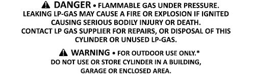
5 SAFETY WARNING FIRE & EXPLOSION HAZARD Gasoline or flammable vapors can ignite or explode. Do not store or use gasoline or other flammable vapors and liquids in the vicinity of this or any other appliance. Follow lighting instructions provided on the label of the fireplace and in this manual. If the information in these instructions are not followed exactly, a fire or explosion may result causing property damage, personal injury or loss of life. VENTILATION Make sure the appliance has proper ventilation as instructed in this manual. Gas vapors can cause personal injury or loss of life. What to do if you smell gas: Do not try to light any appliance No not touch any electrical switch Immediately call gas supplier from a neighbor s phone. Do not use any phone in the building. Follow the gas supplier s instructions If you can not reach your gas supplier, call the fire department. HOT SURFACE HAZARD The glass on the fireplace will become hot while in use. Hot glass will cause burns. Keep children away from hot surface to avoid burns or clothing ignition. Never touch glass until cooled. If burns occur, seek immediate medical attention. 5

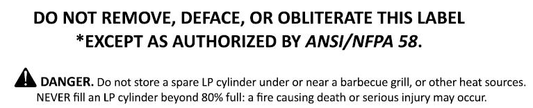
6 SAFETY DANGER CARBON MONOXIDE HAZARD This appliance can produce carbon monoxide which has no odor. Using it in an enclosed space can kill you. Never use this appliance in an enclosed space such as a camper, tent, car or home. DANGER If you smell gas: Shut off gas to the appliance. Extinguish any open flame. If odor continues, keep away from the appliance and immediately call your gas supplier or fire department. WARNING Do not store or use gasoline, or other flammable vapors and liquids, in the vicinity of this or any other appliance. An LP-cylinder not connected for use shall not be stored in the vicinity of this or any other appliance. WARNING Improper installation, adjustment, alteration, service or maintenance can cause injury or property damage. Read the installation, operating, and maintenance instructions thoroughly before installing or servicing this equipment. 6
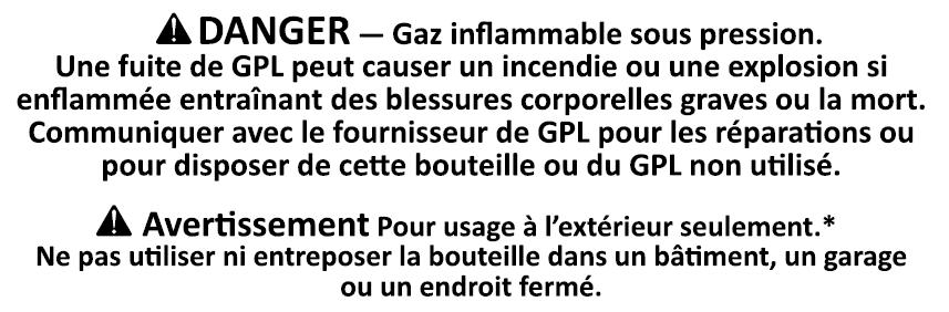
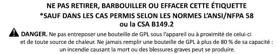
7 SAFETY DANGER MONOXYDE DE CARBONE Cette appareil peut produire du monoxyde de carbon, un gas indore. L utilisation de cet appareil dans des espaces clos peut entraîner la mort. Ne jamais utiliser cet appareil dans un espace clos comme un véhicule de camping, une tente, une automobile ou une maison. DANGER S'il y a une odeur de gaz: Coupez l'admission de gaz de l'appareil. Éteindre toute flamme nue. Si l'odeur persiste, éloignez-vous de l'appareil et appelez immediatement le fournisseur de gaz ou le service d'incendie. ADVERTISSEMENT Ne pas entreposer ni utiliser de l'essence ni d'autres vapeurs ou liquides inflammables dans le voisinage de l'appareil, ni de tout autre appareil. Une bouteille de propoane qui n'est pas raccordée en vue de son utilisation, ne doit pas être entreposée dans le voisinage de cet appareil ou de tout autre appareil. ADVERTISSEMENT Une installation, un ajustement, une modification, une résparation ou un entretien inapproprié peuvent être la cause de blessures ou de dommages. Veuillez lire attentivement les instructions d'installation, d'utilisation et d'entretien avant d'installer ou de réparer ce materiel. 7
8 SAFETY 8
9 SAFETY 9
10 SAFETY Due to high temperatures, the appliance should be located out of traffic and away from furniture and draperies. Clothing or other flammable material should not be placed on or near the appliance. Children and adults should be alerted to the hazards of high surface temperature and should stay away to avoid burns or clothing ignition. Young children should be carefully supervised when they are in the same room as the appliance. Toddlers, young children and others may be susceptible to accidental contact burns. A physical barrier is recommended if there are at-risk individuals in the house. To restrict access to a fireplace or stove, install an adjustable safety gate to keep toddlers, young children and other at-risk individuals out of the room and away from hot surfaces. Any safety screen or guard removed for servicing an appliance, including glass panels, must be replaced prior to operating the appliance. En raison des témperatures élevées, l appareil devrait être installé dans un endroit où il y a peu de circulation et loin du mobilier et des tentures. On ne devrait pas placer de vêtements nid autres matières inflammables sur l appareil ni à proximité. Les enfants et les adultes devraient être informés des danger que posent les températures de surface élevées et se tenir à distance afine d éviter des brûlures ou que leurs vêtements ne s enflamment. Les jeunes enfants devraient êtresurveillés étroitement lorsqu ils se trouvent dans la même pièce que l appareil. Les tout petits, les jeunes enfants ou les adultes peuvent subir desbrûlures s ils viennent en contact avec la surface chaude. Il est recommandé d installer une barrière physique si des personnes à risques habitent la maison. Pour empêcher l accès à l appareil, installez une barrière de sécurité; cette mesure empêchera les tout petits, les jeunes enfants et toute autre personne à risque d avoir accès à la pièce et aux surfaces chaudes. Tout écran ou protecteur retiré pour permettre l entretien de l appareil doit être remis en place avant de mettre l appareil en marche. 10


 The appliance must be isolated from the gas valve supply piping system by closing the equipment shutoff valve during any pressure testing of the gas supply piping system at test pressures")
 CHIMNEY FAN MECHANICAL DAMPER FLUE POWER VENT CLASS A TYPICAL GAS COMPONENTS SHIPPED WITH FIREPLACE GAS VALVE MODULE WITH HARNESS BURNER/FUEL DELIEVRY METHOD PILOT BURNER TRANSFORMER")

11 INSTALLATION GUIDE This is a vented decorative gas appliance: not a source of heat; not for use with solid fuel. IMPORTANT NOTE TO INSTALLER: 1. This appliance is not intended or designed to be installed in a mobile or manufactured home. 2. If this appliance is installed on carpeting, tile, or any combustible material other than wood flooring, the appliance shall be installed on a metal, concrete, or wood panel extending the full width and depth of the fireplace. 3. The appliance and its main gas valve must be disconnected from the gas supply piping system during any pressure testing of that system at test pressures in excess of ½ psi. (3.5 k/pa) The appliance must be isolated from the gas valve supply piping system by closing the equipment shutoff valve during any pressure testing of the gas supply piping system at test pressures equal to or less than ½ psi (3.5 k/pa) CHIMNEY FAN MECHANICAL DAMPER FLUE POWER VENT CLASS A TYPICAL GAS COMPONENTS SHIPPED WITH FIREPLACE GAS VALVE MODULE WITH HARNESS BURNER/FUEL DELIEVRY METHOD PILOT BURNER TRANSFORMER COMPONENT ILLUSTRATION GENERIC SINGLE-SIDED GAS FIREPLACE GLASS COOLING INTAKE OPTIONAL TUBING IGNITION WIRE LINE VOLTAGE LOW VOLTAGE SIGNAL CONTROL WIRING HEAT RELIEF B VENT FAN JUNCTION BOX INCLUDED WITH FAN COMBUSTION INTAKE FAN DISCONNECT SWITCH MEANS AND CIRCUIT PROTECTION TO BE PROVIDED BY INSTALLER 7 W.C. FOR NATURAL GAS AND 11 W.C. FOR PROPANE. THE MAXIMUM INLET GAS-SUPPLY PRESSURE IS 10.5 W.C. FOR NATURAL GAS AND 13 FOR PROPANE TYPICAL CHIMNEY COMPONENTS / OPTIONS SHIPPED WITH FIREPLACE CHIMNEY PIPE EXHAUST FAN WITH ADAPTOR PROVEN SWITCH (PDS) AUTOMATIC CONTROL (ADC) FAN DISCONNECT SWITCH PROVEN SWITCH MUST BE WITHIN 6 FEET OF FLUE. CAN BE LOCATED UP TO 150 FROM ADC 100 GAS LINE GAS VALVE MUST BE WITHIN 60 INCHES OF BURNER COMPONENTS NOT INCLUDED B VENT FOR HEAT RELIEF COMBUSTION INTAKE GLASS COOLING INTAKE UTILITY AND GAS INSTALL` 120 VAC SUPPLY FAN RELAY NOTE: THE INSTALLER(S) OF THIS FIREPLACE AND THE SYSTEM ILLUSTRATED IS RESPONSIBLE FOR PROER GAS AND ELECTRICAL CONNECTIONS FOR SAFE AND RELIALE OPERATION IGNITION CONTROL MODULE 120V AC SUPPLY AUTOMATIC CONTROL FIREPLACE CONTROL SWITCH CAN BE LOCATED UP TO 100 FEET AWAY AT175 TRANSFORMER NOTE: THIS SYSTEM DIAGRAM IS FOR REFERENCE ONLY AND IS INTENDED TO ILLUSTRATE THE GENERAL OUTLINE OF GAS FIREPLACE COMPONENTS AND THEIR RELATIONSHIP WITH CHIMNEY FAN COMPONENTS FOR INDUCED 2015 ACUCRAFT FIREPLACES 11
12 INSTALLATION GUIDE L1 NEUT GND L1 NEUT GND AC IN FAN OUT 24VDC AUX1 IN SENSORS DAMPER VFD OUT Fireplace Wiring Diagram HW RST SW RST PG TIME FAN SPD SW 1 SW 3 AUX2 IN XTP AUX2 OUT /~ -/~ +24V 0-10 GND COM NO L1 NEUT GND L1 NEUT GND + - +/~ -/~ NO NC GND COM NO SIG GND COM NO 0-10 GND COM NO CONFIG SW RELAY PROVE RELAY CONTROL AUX1 OUT Page 12 Acucraft Fireplace Systems nd ST. NW Big Lake, MN PH FAX


13 INSTALLATION GUIDE Positioning the Fireplace Clearance to combustibles: Top of appliance = 4 Sides of appliance = 2 Back of appliance = 2 Bottom of appliance = 0 Vent clearance to combustibles: Class A exhaust flue = 2 B-vent heat relief venting = 1 Using a hand truck or other appropriate equipment, that is rated to handle the weight of the fireplace safely move the fireplace into position. (estimated weight 1500 lbs) AF T IMPORTANT: Clearances must be in accordance with local installation codes and the requirements of the gas supplier. Les dégagements sont conformes aux codes d installation locaux et aux exigences du fournisseur de gaz. R Determine the location of the appliance to ensure that the combustion air supply and the flue gas/chimney pipe connections are to be made as designed. The appliance is designed to sit either directly on the floor or to sit on a base designed to support the weight of the appliance for proper elevation. If shimming is required to level the appliance due to uneven surfaces, shimming the perimeter of the base is the preferred method. Anchor the appliance adequately to prevent future movement. A B D C Note: The appliance should be positioned in a manner that planned electrical and gas line access is available with adequate clearance for servicing. 13 A B C 86 1/
14 INSTALLATION GUIDE Vent terminal locations to intersecting walls, overhangs or eaves, window openings, air intakes, above-ground grade or deck shall maintain the clearances specified as shown below. Vent terminals shall not be recessed into a wall or siding. Installing the Ventilation The entire ventilation system, including Class A exhaust flue, fresh air intakes, and B-Vent heat relief venting are predetermined on this appliance. The venting configuration may or may not include any or all of the following components, depending on design: auto draft control model ADC-100, proven draft switch model PDS-1, or ventilation fans. Exhaust Flue: When installing the UL103HT (Class A) chimney pipe from the fireplace, it must be attached securely to the provided anchor plate. Please consult and follow the manufacturer s instructions included with the chimney pipe and supplied with this manual. If a damper is to be installed in the flue, it must be at a location that meets the manufacturer s specifications, and that is serving only the appliance exhaust. Below drawing: dimensions are located on subsequent page (p.12). CAUTION: Extreme temperatures if damper is not used! Combustion air supply: It is always recommended to minimize any turns or elbows in these supply lines that would cause restriction. Heat relief venting: Requires connecting a single B-Vent flue to a starter collar located and marked on top of the appliance, running from the top of the appliance. Vent Terminal Locations Vents terminating above roofs, whether flat or pitched, must be a minimum of 12 higher than the termination, as shown below. 14
15 INSTALLATION GUIDE A B Clearance above grade, veranda, porch, desk or balcony Clearance to window or door that may be opened C Clearance to permanently closed window D Vertical clearance to ventilated * soffit located above the terminal within a horizontal distance of 2 feet (61 cm) from the center line of the terminal E Clearance to unventilated * soffit F Clearance to outside corner * G Clearance to inside corner * H I J K L M Clearance to each side of center line extended above meter / regulator assembly Clearance to service regulator vent outlet Clearance to nonmechanical air supply inlet to building or the combustion air inlet to any other appliance US installations 2 12in (30 cm) 6 in (15 cm) for appliances 10,000 Btuh (3 kw), 9 in (23 cm) for appliances > 10,000 Btuh (3 kw) and 50,000 Bruh (15 kw), 12 in (30 cm) for appliances > 50,000 Btuh (15 kw) * * * 6 in (15 cm) for appliances 10,000 Btuh (3 kw), 9 in (23 cm) for appliances > 10,000 Btuh (3 kw) and 50,000 Bruh (15 kw), 12 in (30 cm) for appliances > 50,000 Btuh (15 kw) 3 ft (91 cm) above if within 10 ft (3 m) horizontally Clearance to a mechanical air supply inlet Clearance above paved sidewalk or paved driveway located on public property Clearance under veranda, porch deck, or balcony * * Notes: 1) In accordance with the current CSA B149.1, Natural Gas and Propane Installation Code. 2) In accordance with the current ANSI Z223.1/NFPA 54, National Fuel Gas Code. *For clearances not specificed in ANSI Z223.1/NFPA 54 or CSDA B149.1, one of the following shall be indicated: a) A minimum clearance value determined by testing in accordance with Clause , or; b) A reference to the following footnote: Clearance in accordance with local installation codes and requirements of the gas supplier. A vent shall not terminate directly above a sidewalk or paved driveway that is located between two single family dwellings and serves both dwellings. ± Permitted only if veranda, porch, deck, or balcony is fully open on a minimum of two sides beneath the floor. 15
16 SUPPLEMENTAL MATERIAL VENT REQUIREMENTS Vent Requirements Vent Installation The gas appliance and vent system must be vented directly to the outside of the building, and never be attached to a chimney serving a separate solid fuel or gas-burning appliance. Each direct vent gas appliance must use its own separate vent system. In addition to the requirements listed here, follow the requirements provided with the vent. Vent Clearances The vent must maintain the required clearance to combustible materials to prevent a fire. Do not fill air spaces with insulation. Minimum Vent Configurations (elbow directly off fireplace): Clearances are in accordance with local installation codes and requirements of the gas supplier. Les dégagements sont conformes aux codes d installation locaux et aux exigences du fournisseur de gaz. Minimum Clearance Above Vent 2 Minimum Clearance to Sides & Below Vent 2 Vent Firestop A firestop is required whenever the vent penetrates a wall, floor, or ceiling (passes through framing members) Slide the vent sections together, use screws provided with flue (3 screws at each joint). No silicone is required Wall supports are required at a minimum of every 8 feet. Approved Vent Installation instructions for ICC Excel Factory Built Chimney may be found at: 16

17 INSTALLATION GUIDE Connecting the Gas Valve & Ignition System IMPORTANT: All connections and components should be made and installed by qualified persons only and checked and tested for leaks prior to wiring of valve module. Gas supply should be connected as shown below. The location of the stubbed gas line port and electrical pass through port for running the ignition cable are determined during design. The location may either be directly with the fireplace, or these components may be remotely located nearby, but never in a location to exceed 5 length of ignition cable from the burner itself. Please refer to the specific component installation manuals for the electronic gas valve, intermittent pilot module, pilot assembly, and transformer supplied with this fireplace and written by the manufacturer. - Connect the ignition cable and other wiring to the valve and direct intermittent pilot module as shown below. NOTE: These illustrations are not to scale and are for reference only. For more detailed schematics, refer to appropriate components in back of this manual. Directions for Connecting a Gas Pressure Test Gauge The gas control valve (shown to the right) has two test ports for testing input (line pressure) and output (manifold) pressure. Loosen the brass screw on either test port and place a 5/16 i.d. rubber or plastic tube over the tapered test port. Connect the tube to the test gauge. WARNING: The brass screw must be tightened after testing to prevent gas leakage. 17


18 INSTALLATION GUIDE Installing the Media WARNING Always wear protective equipment when dealing with open flames. Failure to follow this warning may result in serious injury. Next, carefully place media over top of round burner located inside of square burner tray, allowing media to fill void alongside tube and to cover over top of tube with ¼ of media, as shown below: This fireplace burner requires a layer of media to cover the burner tube, allowing proper dissipation of the gas flow and propagation of the flame. This should be spread evenly across and completely covering the round burner located inside of the square burner tray, as shown below. First, ensure the pilot shield is in place and flat as shown in the image below: Media should be a consistent depth of 1/2 thick across the burner tube and media tray. The photo below shows the finished look that should be achieved with the media over the burner. The media trays on either side should be filled with the desired media, glass, stones, etc. 18


19 INSTALLATION GUIDE Installing the Dual Pane Glass Step 2: Install the inner frame with the countersunk screws provided WARNING Always wear protective equipment when dealing with hot surfaces. Failure to follow this warning may result in serious injury. T Step 1: Install inner pane of glass in the channel R AF Step 3: Install the outer glass in the channel D Step 4: Install the outer removable frame with the countersunk screws provided 19
20 REPLACEMENT COMPONENTS INFORMATION IMPORTANT: This fireplace system consists of several components that are designed specifically for this appliance. No parts on this appliance may be substituted or replaced with anything other than original components. Replacement parts as listed below can be obtained by contacting Acucraft Customer Service by phone or . Acucraft Customer Service Contact Information: Phone: (763) COMPONENT DESCRIPTION INSTALL INFORMATION PAGE(s) Flue / Venting Glass Media 18 Glass Panels 19 Draft Controller Gas Valve & Ignition Module Draft Switch Chimney Fan WARNING: Failure to position the parts in accordance with these diagrams or failure to use only parts specifically approved with this appliance may result in property damage or personal injury. AVERTISSEMENT: Risque de dommages ou de blessures si les pièces ne sont pas installées conformément à ces schémas et ou si des pièces autres que celles spécifiquement approuvées avec cet appareil sont utilisées. 20

21 SUPPLEMENTAL MATERIAL Product Information Draft Controller USE: The Control Board is a fan speed and appliance control used to control draft for a gas appliance such as a fireplace, stove or furnace. It may be interlocked with the appliance and is for use in systems where modulation is not required. It controls the speed of a fan to maintain proper draft and pressure in a chimney system. The Control Board is for use with chimney fans. FUNCTION: The Control Board comes with the Draft Switch. The Draft Switch is a required safety function used to ensure a negative pressure is maintained in the chimney. It also prevents appliance operation during an electrical or mechanical failure in the system. The Control Board can operate the chimney fan in manual or automatic mode. Manual mode allows the user to adjust the speed of the fan at any time using the potentiometer on the board. In Automatic Mode, the Control Board will ignore the potentiometer and ramp the fan up until the Draft Switch closes. If the Draft Switch opens, the control will ramp up the fan until there is enough draft to re-close the switch. CONSTRUCTION: The housing is NEMA 1 rated ABS plastic. CODE COMPLIANCE: System installation must conform to the requirements of the authority having jurisdiction. When required by the authority having jurisdiction, the installation must also conform to the NFPA31, NFPA54 or NFPA211. All electrical wiring must be in accordance with the requirements of the authority having jurisdiction or, in absence of such requirements, with the National Electric Code, NFPA 70. Shipping Information The Control Board includes the control unit, Draft Switch, stack probe and silicone tubing. * If other components are shipped, they will appear as separate items on the packing list. 21
22 SUPPLEMENTAL MATERIAL Specifications Draft Controller Mechanical Installation Dimensions & Capacities: Power Supply = V 1x120 VAC Amperage = A 6.3 Operating Temp = ºF/ºC -4 to 122 / -20 to 50 Control Signal = ma max. 10 Control relay max. 120 VAC / 8A Output VAC = VDC = 0-10 Post Purge Time 0-3 Minutes Alarm Delay Time 15 Seconds Dimensions (see below) Weight = lbs/kg 2.6 / 1.2 Dimensions Control Board A 9.6 in / 244 mm B 6.3 in / 160 mm C 3.5 in / 90 mm Chimney Probe D 4.25 in / 108 mm E 3.50 in / 89 mm LOCATION: The Control Board must be installed indoors. As shown in the diagram below, the control will be wired directly to a 120/1/60 VAC power supply. The control will also be connected to the fan, appliance and damper (if used). For detailed wiring information, see Electrical Installation. CONTROL SWITCH Fireplace MOUNTING THE CONTROL UNIT: The Control Board may be mounted directly to a wall. To mount, remove the cover and locate the (4) mounting holes. Using the hole-pattern shown below, mount the control using #6 screws. Once it is attached, wire the unit in accordance with Electrical Installation section of this manual. 22
23 SUPPLEMENTAL MATERIAL Draft Controller CONNECTION OF THE SWITCH AND STACK PROBE: The Draft Switch must be installed indoors, in the vertical position (pre-drilled knockouts face down). Mount the control upright to a wall or other flat surface. Do NOT lay the control down or mount horizontally. A Draft Switch must be used with the Control Board as a system safety device. The Draft Switch monitors the pressure inside the stack and signals the control to shut down the appliance if insufficient draft exists. A stack probe senses the pressure read by the Draft Switch and is connected via silicone tubing. The silicone tubing supplied with the Draft Switch should be connected to the NEGATIVE (-) port of the Draft Switch. This is the bottom port on the switch. The standard tube length is 6 feet. The distance can be extended up to 25 feet by using 1/4 rigid plastic or copper tubing as temperature allows (not supplied). The image below is for reference only; the draft switch must be installed in a vertical position. INSTALLATION OF THE CHIMNEY PROBE: The probe must be installed between the appliance and the exhaust fan. If a damper is used in the system, the probe should be installed between the appliance and damper. Locate the probe at least a distance three (3) vent diameters away from any elbow, tee or damper. For fireplace installations, the probe should be installed close to the fan inlet as shown below. To produce an accurate pressure reading, the probe should be installed flush with the inner wall of the chimney or stack. If double walled stack is used, the probe should be flush with the inner most wall. 23

24 SUPPLEMENTAL MATERIAL Gas Valve & Ignition Module Pilot burners provide main burner ignition for standing pilot natural and LP gas systems. Used with a thermocouple to provide automatic pilot safety control. Used with a thermopile in a self-powered system. See Table 1 for model specifications. TABLE 1 - MODEL SPECIFICATIONS MODEL PRIMARY AERATED TYPE OF ORIFICE INSTALLATION PILOT TIP TYPE Q314A No Insert Target Q327A Yes Spud Target WHEN INSTALLING THIS PRODUCT Read these instructions carefully. Failure to follow instructions can damage product or cause hazardous condition. 2. Check ratings given in instructions and on product to make sure product is suitable for your application. 3. Make sure installer is a trained, experienced service technician. 4. After completing installation, use these instructions to check out product operation. INCLUDES Includes natural and LP gas orifices, 1/4 in. compression fitting, F, K, or L tip styles, B mounting bracket, and A mounting bracket adapter Includes natural and LP gas orifices, 1/4 in. compression fitting, and B mounting bracket with screws identical unit and position new pilot burner in the same location and orientation as the original pilot burner. 2. Mount pilot burner on main burner. Mounting surfaces other than the main burner can shift, bend, or warp as furnace expands and contracts while operating. See Fig Mount pilot burner so the ignition flame remains properly positioned with respect to the main burner flame. See Fig Supply pilot flame with ample air free of combustion products. 5. Do not impinge pilot flame on adjacent parts. Do not impinge main burner flame on pilot burner. 6. Do not expose pilot flame to falling scale which could impair ignition of main burner. 7. Do not expose pilot burner to main burner rollout while igniting or extinguishing. 8. Do not expose pilot flame to drafts that push or pull pilot flame away from the thermocouple or thermopile. Follow appliance manufacturer s instructions if available; otherwise, use instructions provided below. LOCATION 1. Position pilot burner for easy access, observation, and lighting. In replacement applications, replace pilot burner with an 24
25 SUPPLEMENTAL MATERIAL Gas Valve & Ignition Module ATTACHMENT NUT DESIGN 1. Insert thermocouple or thermopile tip into hole or barrel provided beneath burner. See Figs. 4 and Engage attachment nut threads and tighten until thermocouple or thermopile is locked into place. CONNECT PILOT GAS TUBING 1. Cut tubing to desired length and bend as necessary for routing to pilot burner. Do not make sharp bends or deform tubing. Do not bend tubing at control after compression nut has been tightened, as this can result in gas leakage at connection. 2. Square off and remove burrs from end of tubing. 3. Push tubing into compression nut clearance hole until tubing bottoms. NOTE: When replacing a pilot burner or orifice, cut off old compression fitting and replace with new compression fitting provided with new pilot burner. Never use old compression fitting as it may not provide a gas-tight seal. See Fig While holding tubing all the way in, engage threads and turn until finger tight. 5. Using a wrench, turn compression nut one turn beyond finger tight. DO NOT OVERTIGHTEN. 6. Connect other end of tubing to gas control according to gas control manufacturer instructions. INSTALL BLEED GAS TUBING (if used): 1. Route bleed gas tubing from bleed tapping on gas control to the pilot burner. 2. Push clip into place. See Fig Insert bleed gas tubing until 3/8 inch (10mm) of tubing is above pilot burner bracket. Tip of bleed gas tubing must not extend into pilot flame. INSTALL THERMOCOUPLE OR THERMOPILE PUSH-IN DESIGN 1. Insert thermocouple or thermopile tip into hole or barrel provided beneath pilot burner. See Fig Push in firmly until thermocouple or thermopile is locked into place. INSTALL A MOUNTING BRACKET ADAPTER (optional) To convert mounting bracket from B mounting bracket to A mounting bracket, install the A mounting bracket adapter to the pilot burner mounting bracket. Then install pilot burner to main burner. 25
26 SUPPLEMENTAL MATERIAL Gas Valve & Ignition Module CHANGE INSERT ORIFICES (See Fig. 7) 1. Disconnect pilot tubing from the pilot burner and remove insert orifice. Sometimes a light force is required to remove the orifice. 2. Cut off old compression fitting. NOTE: When replacing an orifice, cut off old compression fitting and replace with a new compression fitting. Never use old compression fitting as it may not provide a gastight seal. See Fig Square off end of pilot tubing and remove all burrs. 4. Insert new compression nut over pilot tubing and slide out of the way. 5. Insert new orifice into pilot burner and push pilot tubing into the pilot burner until it bottoms. 6. While holding tubing all the way in, slide compression fitting into place and engage threads. Turn until finger tight. 7. Using a wrench, tighten compression fitting one turn beyond finger tight. 8. CHANGE SPUD ORIFICES (See Fig. 7) 1. Disconnect pilot tubing from orifice. 2. Unscrew old spud orifice and discard. 3. Cut off old compression fitting. NOTE: When replacing an orifice, cut off old compression fitting and replace with a new compression fitting. Never use old compression fitting as it may not provide a gastight seal. See Fig Square off end of pilot tubing and remove all burrs. 5. Insert new compression nut over pilot tubing and slide out of the way. 6. Insert new orifice into pilot burner and tighten securely. 7. Push pilot tubing into orifice until it bottoms. 8. While holding tubing all the way in, slide compression fitting into place and engage threads. Turn until finger tight. 9. Using a wrench, tighten compression fitting one turn beyond finger tight. 26 GAS LEAK TEST: 1. Ensure that gas supply is turned on at the appliance service valve. 2. Paint pipe connections upstream of pilot burner with rich soap and water solution. Bubbles indicate gas leak. 3. If leak is detected, tighten pipe connections. 4. Stand clear of main burner while lighting to prevent injury caused from hidden leaks which could cause flashback in the appliance vestibule. Light main burner. 5. With main burner in operation, paint pipe joints (including adapters) and gas control inlet and outlet with rich soap and water solution. 6. If another leak is detected, tighten adapter screws, joints, and pipe connections. 7. Replace part if leak cannot be stopped. ADJUST PILOT FLAME The pilot flame should envelop 3/8 to 1/2 in. [10 to 13 mm] of the thermocouple or thermopile tip. See Fig. 8. To adjust pilot flame: 1. Remove pilot adjustment cover screw from gas control. 2. Turn inner pilot adjustment screw clockwise to decrease or counterclockwise to increase pilot flame. 3. Always replace pilot adjustment cover screw and tighten firmly after completing adjustment to ensure proper operation.
27 SUPPLEMENTAL MATERIAL Gas Valve & Ignition Module IGNITE PILOT BURNER 1. Before lighting pilot burner, turn thermostat to its lowest setting. Wait for unburned gas to vent. NOTE: LP gas is heavier than air and will not vent upward. Smell for LP gas next to floor. If you smell gas, shut off the main valve in the gas piping, or, ON LP, AT THE TANK. Perform Gas Leak Test to recheck all connections. 2. Light pilot burner according to appliance manufacturer s instructions. PILOT OUTAGE 1. If pilot flame goes out during normal operation, but is properly adjusted, recheck Mounting and Location instructions on page If all mounting and location instructions are followed but pilot continues to go out, construct shielding to protect pilot flame from main burner ignition and extinction and drafts. See Fig Check pilot flame characteristics. Check the pilot flame with the main burner operating. Ensure the pilot flame continuously covers the tip of the thermocouple or thermopile, the spark gap and 3/8 to 1/2 in. (10 to 13 mm) of the ground rod. See Fig. 8. Ensure the pilot flame is blue (a yellow tipped flame is acceptable on LP systems), soft and steady. See Fig. 9 for examples of possible pilot flame problems and their causes. If pilot burner is damaged, replace it with an identical pilot burner and mount and position in the same location and orientation. PILOTSTAT SAFETY CONTROL POWER UNIT FAILURE 1. Ensure pilot flame is properly adjusted. 2. Ensure power unit connections clean and tight. 3. If power unit still fails to hold in, use the W129A Millivoltmeter to obtain the open and closed circuit voltage generated by the thermocouple or generator. 4. Compare measured open and closed circuit voltage values to Acceptable Range Charts in W129A Manual. 5. If W129A Millivoltmeter or other meter is not available, replace thermocouple or thermopile. If this does not correct the condition, replace power unit. THERMOCOUPLE OR THERMOPILE PERFORMANCE Thermocouples and thermopiles require proper temperature differential between the hot-junction (tip) and coldjunction (base) to provide satisfactory operation of gas controls. Thermocouples and thermopiles perform less effectively when exposed to excessive cold-junction or hotjunction temperatures. Excessive cold-junction temperatures can be caused by heat radiation from adjacent surfaces or high ambient air temperatures. Excessive cold-junction temperatures can be eliminated by shielding the pilot flame, see Fig. 10, or constructing a baffle to direct secondary air over the pilot burner base. Excessive hot-junction temperatures can be eliminated by proper pilot flame adjustment. To adjust pilot flame, see Adjust Pilot Flame section. 27
28 SUPPLEMENTAL MATERIAL Gas Valve & Ignition Module EFFECTIVE IGNITION TEST (750 mv SYSTEMS) PILOT TURNDOWN TEST (30 mv safety control systems) The Pilot Turndown Test assures that the pilot flame ignites the main burner within four seconds from the time gas reaches the main burner. In this test, the pilot flame is just sufficient enough to hold in the power unit or just above the point of flame extinction (whichever occurs at a higher pilot gas flow rate). 1. With the pilot and main burner operating, shut off the main burner by either lowering the thermostat temperature setting or turning the gas control knob to the PILOT position. NOTE: If using a Honeywell W129A Millivoltmeter, turn the pilot gas adjustment screw until the thermocouple open circuit voltage is 2 mv. Omit steps 2,3, and 4 and proceed with step Turn the pilot gas adjustment screw clockwise until the pilot begins to decrease in size. Then, turn the pilot gas adjustment screw clockwise 1/4 turn a time (waiting one minute between each turn to allow the thermocouple to cool) until safety shutoff power unit just drops, causing safety shutdown. 3. Turn pilot gas adjustment screw counterclockwise slightly. 4. Relight pilot burner. The power unit should hold in. 5. Turn gas control knob to ON position and set thermostat temperature setting above room temperature. Main burner should light within four seconds without flame rollout. If not, check pilot mounting and location instructions in Location section and repeat Pilot Turndown Test. 6. Readjust pilot burner flame. See Adjust Pilot Flame section. The Effective Ignition Test assures that the pilot flame ignites the main burner within four seconds from the time gas reaches the main burner. In this test, the pilot flame is just sufficient to open the main gas valve. 1. Light the main burner according to the appliance manufacturer s instructions and allow to burn at least five minutes. 2. Remove one thermostat lead (TH) at the gas control terminal. 3. Using the pilot gas adjustment screw, decrease the pilot flame until it begins to pull away from the thermopile. Allow thermopile to cool for one minute. 4. Temporarily jumper the thermostat terminals (TH) on the gas control. 5. If the main burner ignites, reduce the pilot flame by turning the pilot adjustment screw 1/4 turn at a time until the valve fails to pull in. Allow the thermocouple to cool at least one minute between each reduction in the pilot flame level. 6. Increase the pilot flame just enough to pull in the gas control main valve. 7. Jumper the thermostat terminals. The main burner should light within four seconds and without flame roll-out. If it does not, check the Location and Mounting instructions. 8. If main burner still does not light, replace thermopile and repeat steps 1 through Remove the jumper to shut off the main burner. 10. Readjust pilot burner flame. See Adjust Pilot Flame section. 11. Reconnect the thermopile lead and ensure all connections are correct and the system is functioning properly. 28
29 SUPPLEMENTAL MATERIAL Mechanical Installation Draft Switch INSTALLATION OF SWITCH The Draft Switch is for indoor installation only. The Draft Switch must be installed in a vertical position with the pressure connection pointing down. Secure the switch by using the mounting holes as shown on the gure. After installation connect the tubing from the probe onto the port marked accessible through the small of the plastic enclosure. Connect tubing to the NEGATIVE (-) port on the Draft Switch. Factory wiring comes with three wires that are already crimped onto the Draft Switch. The purpose of these wires is to provide a point in which you can extend the length of the wire by using wire nuts and additional wire (not provided). INSTALLATION OF STACK PROBE FOR PDS 1: A stack probe is used with Draft Switch. The Draft Switch monitors the pressure inside the stack and signals the control to shut down the appliance if insuffcient draft exists inside the stack. The probe must be installed between the appliance and the exhaust fan. For all installations, the stack probe must be placed so the flow through the stack is perpendicular to the tip of the probe. Locate the probe at least the distance A away from any elbows or tees in the stack. The distance A is designed as at least three (3) vent diameters; A 3 *V (see figure below). To prevent condensation from entering the probe or Draft Switch when installed on a horizontal stack, the probe must be installed above the centerline of the stack. For replace installations, the stack probe should be installed as close to the exhaust fan as possible. 29
30 SUPPLEMENTAL MATERIAL Draft Switch For all installations, the stack probe must be placed so the flow through the stack is perpendicular to the tip of the probe. Locate the probe at least the distance A away from any elbows or tees in the stack. The distance A is designed as at least three (3) vent diameters; A 3 *V (see figure below). To prevent condensation from entering the probe or Draft Switch when installed on a horizontal stack, the probe must be installed above the centerline of the stack. For replace installations, the stack probe should be installed as close to the exhaust fan as possible. Mechanical Installation (cont.) INSTALLATION OF STACK PROBE FOR Draft Switch (cont.): For the Draft Switch to function properly, the probe must be placed in a location that can produce at least 0.05 in/wc in the stack. In order to produce an accurate pressure reading, the tip of the probe must be mounted flush with the inside of the stack wall (it should never extend more than 1/16 beyond the wall). For a double walled stack, the tip should be flush with the inner most wall. To mount the probe, drill a clearance hole through the stack wall(s). Insert the probe and attach the bracket to the stack using (2) customer provided self-tapping machine screws. Tighten the end cap to compress the ferrule and permanently install the stack probe. Attach the supplied silicon tubing at the other end of the probe. 30
 450 Amperage (Amps) 0.5 Motor Output (HP) 1/30 Motor Output (kw) 0.025 Weight (lbs) 29 Weight (kg) 13 Dimensions A (In) 10.2 Dimensions A (mm) 259 B x B (In) 11.")
31 SUPPLEMENTAL MATERIAL Chimney Fan Dimensions & Capacities Model Sound Data: Discharge Fan Type Motor Type 31 Chimney Fan Horizontal Axial Vane Totally enclosed, variable speed, Class H Voltage (VAC) 1 x 120 RPM 1600 CFM (0.0Ps) 450 Amperage (Amps) 0.5 Motor Output (HP) 1/30 Motor Output (kw) Weight (lbs) 29 Weight (kg) 13 Dimensions A (In) 10.2 Dimensions A (mm) 259 B x B (In) 11.7 B x B (mm) 296 C (In) 10.8 C (mm) 275 D (In) 3.0 D (mm) 75 E (In) 9.4 E (mm) 238 Temperature (Intern.) 575 F/300 C 1. Junction Box 2. Conduit / Cord 3. Motor 4. Motor Housing 5. Cooling Plates 6. Bird Screen 7. Base Plate 8. Locking Nut 9. Inlet 10. Axial Vane 11. Hinges 12. Capacitor (Inside Junction Box)
32 SUPPLEMENTAL MATERIAL Planning Ahead WARNING 1. Observe proper combustion air requirements. 2. Provide a firm support system for the chimney fan. 3. Determine the type of system involved. 4. Observe proper safety measures are taken to assure safe use of the wood burning appliances. Combustion Air Requirements: Provisions for combustion air must be in accordance with applicable local codes. If the heating system is installed in an unconfined space, adequate air will be available via normal infiltration. If the heating system in installed in a confined space, (a space with a volume less than 50 cubic feet per 1,000 Btu/hr of input for all fuel burning equipment) or building construction is unusually tight, adequate air for combustion must be provided by two openings: one located about 6 below the ceiling, the other about 6 above the floor. Each opening must have a minimum free area as follows: 1. On square inch per 2,000 Btu/hr when communication through horizontal ducts to the outside. 2. One square inch per 1,000 Btu/hr when ventilation air is provided by openings in doors, etc. to adjoining spaces having adequate infiltration. Chimney Fan Support system for the chimney fan: Prior to installation of the chimney fan, it must be assured the chimney can safely carry the weight of the chimney fan. A steel chimney should be well supported at the roof penetration point. WARNING Adequate fresh air must be provided for combustion; otherwise, improper operation and inadequate venting of deadly flue gases may result. 32


33 SUPPLEMENTAL MATERIAL Chimney Fan Single Fan on Steel Chimney Step 1: Prepare fan location The steel chimney adapter (SCA) slides right into the chimney, where the long collar engagement ensures safe anchoring. CAUTION Under conditions with extremely strong winds surrounding the top of the chimney, the chimney fan must be secured by steel wires supplied with the fan. Step 2: Preparation of fan Locate the installation brackets in the grooves on the underside of the fan base, using the bolts and nuts supplied to secure the brackets. Note that the bolts shall be installed from the bottom side in the two inner holes. Adjust the final position of the installation brackets ensuring that there is a small gap between the brackets and the flue wall/adapter throat. Tighten the nuts. If the brackets touch the flue wall, it may create some vibration noise. Step 3: Attaching the fan The chimney fan is now ready for installation on the top of the chimney. It is not necessary to bolt the fan to the chimney. High temp silicone Wall Mounting of Chimney Fan When mounting the chimney fan on a wall, the installation instructions for installation on a steel chimney should be followed. Use of the adapater SCA can make the installation easier. To ease installation, detach the fan base by removing the bolts holding the hinges together. Center the fan base over the outlet and bolt the base onto the wall with the hinges pointing upwards. After mounting the base securely, attach the fan motor housing by reassembling the fan hinges. Seal with high temp silicone all around the edges. 33
34 SUPPLEMENTAL MATERIAL Chimney Fan CAUTION A safety device that prevents the heating appliance operation, in case of a power failure or inadequate draft situation, must be installed. Termination of Venting System In order to achieve optimal performance and energy consumption for the RS Fan the duct must be installed as shown below and the distances observed. From the last elbow to the termination point the distance has to be 3 times the diameter of the flue. For example if you using 12in flue (12 X 3 = 36in). So the distance from the last elbow to the fan termination point should be 36 inches. A venting system that terminates in the sidewall of a structure shall terminate at least 3 ft (0.9 m) above any air inlet to the structure that is within 10 ft (3 m) of the termination point. Exception No. 1: This requirement shall not apply to the combustion air intake of a direct vent appliance. Exception No. 2: This requirement shall not apply to the separation distance between the circulating air inlet and the vent discharge of a listed outdoor appliance. The flue gas outlet of an appliance other than a direct vent appliance shall terminate at least 4 ft (1.2 m) below, 4 ft (1.2 m) horizontally from, or 1 ft (0.3 m) above any door, window, or gravity air inlet of the structure. The outlet also shall terminate at least 1 ft (0.3 m) above grade. The combustion air inlet and flue gas outlet of a direct vent appliance or the flue gas outlet of an appliance other than a direct vent appliance shall terminate at least 1 ft (0.3 m) from the soffit of the roof of the structure and at least 3 ft (0.9 m) from an inside corner of an L-shaped structure. The flue gas outlet terminal of a direct vent application with an input of 50,000 Btu/hr (0.35 gal/hr) or less shall be located at least 9 in. (230 mm) from any door, window, or air inlet to the structure. The vent terminal of a direct vent appliance with an input over 50,000 Btu/hr (0.35 gal/hr) shall be located at least 1 ft (0.3 m) from any door, window, or air inlet to the structure. Regardless of input, the flue gas outlet terminal shall also terminate at least 1 ft (0.3 m) above grade. The exit terminals of mechanical draft systems shall not be less than 7 ft (2.1 m) above grade when located adjacent to public walkways. Any air inlet and any flue gas outlet of any appliance shall terminate at least 5 ft (1.6 m) from the vent outlet of a supply tank. Electrical Installation WARNING Turn off electrical power before servicing. Contact with live electric components can cause shock or death. All electrical wiring must be in accordance with requirements of authority having jurisdiction or, in absence of such requirements, with National Electrical Code NFPA 70 latest edition. If an external electrical source is utilized, system must be electrically grounded in accordance with requirements of the authority having jurisdiction or, in the absence of such requirements, with the National Electrical Code NFPA 70 latest edition. 34

35 SUPPLEMENTAL MATERIAL Start-Up and Configuration Chimney Fan SYSTEM TESTING Before any adjustments are made to the system, follow these procedures: 1. Turn the chimney fan ON and make sure that it is operating. Increase and decrease the speed of the fan by adjusting the fan speed control to make sure it is operating properly. 2. Turn the fan OFF and make sure the pressure switch opens, so the power to the circuit, it controls, is disconnected. WARNING Check other heating appliances (water heater, furnace, fireplace etc.) for proper operation while the chimney fan is operating. Make sure no flue gases are spilling out as this can lead to carbon monoxide poisoning. Maintenance PRIOR TO CLEANING Remove butterfly nut or screw from each hinge prior to cleaning. CARE AND CLEANING The Chimney Fan System is designed for prolonged use. The fan should be inspected at least once a year when the chimney is inspected. Fuel residues and other deposits should be removed from the fan blades and the bottom of the motor housing. The top of the fan is hinged and can be opened in order to ease the cleaning. WARNING Do not open the motor housing unless power to the chimney fan has been disconnected. 35
36 SUPPLEMENTAL MATERIAL Chimney Fan Maintenance (cont.) CHIMNEY CLEANING INTERVALS It is extremely important to keep the chimney flue clean from products of combustion and deposits. Unburned oil residues can cause a chimney fires. Cleaning intervals depend on the use of the appliance. The more the appliance is used, the more often the chimney flue needs cleaning. As there are no firm guidelines for cleaning intervals, have the chimney inspected on a regular basis (every quarter or so) to determine what the interval should be. Then follow this interval. No matter how much used, a chimney flue should be cleaned and inspected at least once every year. NOTE: The chimney should be cleaned by a trained professional. We recommend using a Certifed Chimney Sweep certified by Chimney Safety Institute of American. You can find a Certified Chimney Sweep at org or or by calling (317) or (317) Troubleshooting OBSERVATION PROBLEM SOLUTION There is no power going to the fan - The circuit breaker may be off - Fan speed control is off - Bad electrical connections - Check the circuit breaker - Turn fan speed contron control on - Check and correct problem There is power to the fan but it is - Bad electrical connections - Check and correct problems with not operating - The fan speed control s low connections. Pay special attention voltage setting is too low to the wiring in the junction box - The fan speed control is bad - Increase the setting with the plastic screw on the fan speed control s front plate - Replace the fan speed control There is power to the fan but it hums and does not turn - The motor run capacitor may be bad. - Creosote may stick - Check capacitor and replace if necessary - Clean fan The fan seems to work fine, but - The fan may be undersized - Replace with a larger fan there is not enough draft The fan vibrates - The motor shaft may be bent - The hinges may be bent - Replace motor - Straighten out hinges There is airflow noise from the draft hood - The flue is undersized. - The fan is oversized and running - There is not much to do about it - Reduce the fan speed too fast Mechanical noise can be heard - Foreign matter may be stuck - Motor bearings may be worn out - Remove matters foreign matter - Replace bearings 36
37 NOTES
 0-1370 m = 150,000 BTUs/hr.")
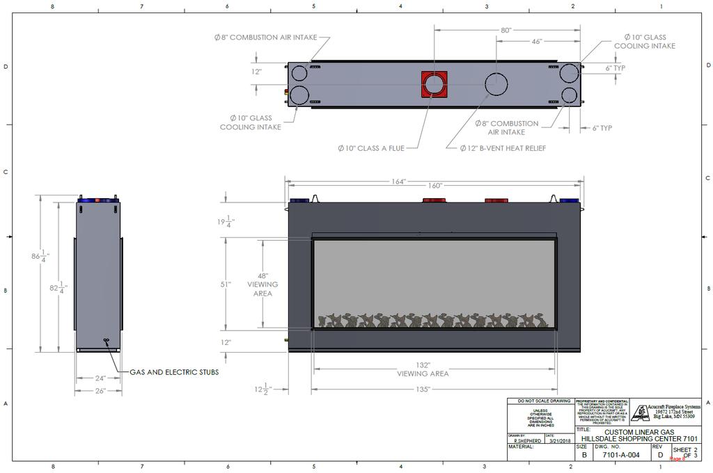
38 PRODUCT SPECIFICATIONS Height = 82 1/4 Width = 160 Depth = 24 Appx Weight. = 1,750 LBS Gas Type = Natural Gas Flue Size = 10 Flue Type = 103HT Electrical = Single 15 AMP service NATURAL GAS SPECIFICATIONS Input Rating (BTU/hr) m = 150,000 BTUs/hr. Minimum inlet pressure (in.w.c.) = 7.0 in. W.C. Maximum inlet pressure (in.w.c.) = 10.5 in. W.C. Combustion Air inlet size= DUAL 8 Round Glass Cooling Air inlet size = DUAL 10 Round Based on testing that was performed, the following results have been recorded. Minimum Clearances to combustibles Unit to back wall of enclosure = 2 Unit to sidewall of enclosure = 2 Unit top to enclosure top = 4 NOTE: A 8 B-Vent used as a duct to remove heat from the top to the outdoors must be installed to maintain these clearances. (SUPPLIED BY OTHER) Note: The chimney flue for the appliance should never be connected to another chimney flue in any way. 38
39 PRODUCT SPECIFICATIONS 39
Vulcan Fire Module WARNING. For Use with NATURAL or LP GAS Only NO SOLID FUELS TO BE USED WITH THIS SYSTEM
 www.inspiredfirefx.com Vulcan Fire Module (VFM) Owner s Manual Installation and Operation Vulcan Fire Module Certified by Lab Test Certification Meets: ANSI Z21.97-2014 CSA 2.41-2014 CSA C22.2 No. 3-M1998
WARNING. For Use with NATURAL or LP GAS Only NO SOLID FUELS TO BE USED WITH THIS SYSTEM
 www.firebydesign.com Wharf DC Branch Twist Fire Feature Owner s Manual Installation and Operation Certified by Underwriters Laboratories Meets: ANSI Z21.97-2014 CSA 2.41-2014 CSA C22.2 No. 3-M1998 (R2014)
WARNING WARNING WARNING. For Use with NATURAL or LP GAS Only NO SOLID FUELS TO BE USED WITH THIS SYSTEM
 theoutdoorplus.com Owner s Manual Electronic Ignition Commercial Grade System Installation and Operation Improper installation, adjustment, alteration, service or maintenance can cause injury or property
Installation/Operator s Manual. Serial #: Acucraft Custom Linear See Through with Panoramic Corners Gas Fireplace
 Acucraft Custom Linear See Through with Panoramic Corners Gas Fireplace Serial #: 7459 This is a vented decorative gas appliance: not a source of heat; not for use with solid fuel. Cette unité est appareil
An LP-cylinder not connected for use shall not be stored in the vicinity of this or any other appliance. WARNING
 www.inspiredfirefx.com Commercial Grade All Weather Electronic Ignition System (Lateral Offset) Owner s Manual Installation and Operation Certified by Lab Test Certification Meets: ANSI Z21.97-2014 CSA
WARNING. For Use with NATURAL or LP GAS Only NO SOLID FUELS TO BE USED WITH THIS SYSTEM
 Outdoorfiredesigns.com Automated Tiki Torch (AWEIS) Owner s Manual Installation and Operation Certified by Lab Test Certification Meets: ANSI Z21.97-2014 CSA 2.41-2014 CSA C22.2 No. 3-M1998 (R2014) Improper
WARNING. For Use with NATURAL or LP GAS Only NO SOLID FUELS TO BE USED WITH THIS SYSTEM
 www.firebydesign.com All Weather Electronic Ignition Commercial Grade System Owner s Manual Installation and Operation (LINEAR FEATURES) Improper installation, adjustment, alteration, service or maintenance
WARNING. For Use with NATURAL or LP GAS Only NO SOLID FUELS TO BE USED WITH THIS SYSTEM
 www.firebydesign.com All Weather Electronic Ignition Commercial Grade System Owner s Manual Installation and Operation (ROUND/SQUARE FEATURES) Improper installation, adjustment, alteration, service or
WARNING Do not store or use gasoline or other flammable vapors and liquids in vicinity of this or any other appliance. WARNING
 www.theoutdoorplus.com (909) 460-5579 All Weather Electronic Ignition System (12 Volt AC) Owner s Manual Installation and Operation Certified by Lab Test Certification Meets: ANSI Z21.97-2014 CSA 2.41-2014
Q382A,B Pilot Burners
 Q382A,B Pilot Burners INSTALLATION INSTRUCTIONS APPLICATION The Q382A,B Pilot Burners provide main burner ignition for natural and LP gas-fired equipment. The design makes them ideal for use with any millivolt
An LP-cylinder not connected for use shall not be stored in the vicinity of this or any other appliance. WARNING
 www.firebydesign.com All Weather Electronic Ignition System (AWEIS) Owner s Manual Installation and Operation Certified by Lab Test Certification Meets: ANSI Z21.97-2014 CSA 2.41-2014 CSA C22.2 No. 3-M1998
200i User s information manual
 M2i-UM-1 WARNING: If the information in this manual is not followed exactly, a fire or explosion may result, causing property damage, personal injury or loss of life. Cast iron condensing boiler 200i User
User s Manual for FT SERIES THE
 User s Manual Document 1343D User s Manual for THE FT SERIES Wall-Mounted, Modulating Gas, Condensing, Heating Only, Boiler Model FTHW 80,000 BTU/hr 100,000 BTU/hr 120,000 BTU/hr 140,000 BTU/hr 199,000
GRAVITY DIRECT VENT WALL FURNACE
 OWNER S OPERATION AND INSTALLATION MANUAL FOR MODELS DVEL 8, DVEL 12, DVEL 20 WARNING: If the information in this manual is not followed exactly, a fire or explosion may result causing property damage,
APEX CONDENSING HIGH EFFICIENCY GAS-FIRED HOT WATER BOILER
 USER'S INFORMATION MANUAL APEX CONDENSING HIGH EFFICIENCY GAS-FIRED HOT WATER BOILER If the information in this manual is not followed exactly, a fire or explosion may result causing property damage, personal
Mascot LX. User s Information for. Wall-Mounted, Modulating Boiler Model MLXH 50, 75, 100, 125, 150, 175, & 220 MBH
 User s Manual Document 1286A User s Information for Mascot LX Wall-Mounted, Modulating Boiler Model MLXH 50, 75, 100, 125, 150, 175, & 220 MBH Combination Boiler Model MLXC 125, 150 and 175 MBH FOR YOUR
Alpine CONDENSING HIGH EFFICIENCY GAS-FIRED HOT WATER BOILER
 USER'S INFORMATION MANUAL Alpine CONDENSING HIGH EFFICIENCY GAS-FIRED HOT WATER BOILER If the information in this manual is not followed exactly, a fire or explosion may result causing property damage,
USER'S INFORMATION MANUAL ES2 GAS - FIRED
 USER'S INFORMATION MANUAL ES2 GAS - FIRED BOILER WARNING: If the information in this manual is not followed exactly, a fire or explosion may result causing property damage, personal injury or loss of life.
USER'S INFORMATION MANUAL SERIES 2 GAS - FIRED
 USER'S INFORMATION MANUAL SERIES 2 GAS - FIRED BOILER WARNING: If the information in this manual is not followed exactly, a fire or explosion may result causing property damage, personal injury or loss
USER'S INFORMATION MANUAL SERIES 2 GAS - FIRED
 USER'S INFORMATION MANUAL SERIES 2 GAS - FIRED BOILER : If the information in this manual is not followed exactly, a fire or explosion may result causing property damage, personal injury or loss of life.
RS Chimney Fan For Gas & Oil Applications. Installation & Operating Manual USA CAN
 Installation & Operating Manual 3000270 10.01 USA CAN RS Chimney Fan For Gas & Oil Applications 1200 Northmeadow Parkway, STE 180 Roswell, GA 30076 (770) 587-3238 (800) 255-2923 Fax (770) 587-4731 info@exhausto.com
- Do not store or use gasoline or other
 USER'S INFORMATION MANUAL ALPINE CONDENSING HIGH EFFICIENCY GAS - FIRED HOT WATER BOILER WARNING: If the information in this manual is not followed exactly, a fire or explosion may result causing property
installation manual DM3862 RM2554 DM2663 RM2551 Refrigerator for LP-gas & electric operation DM2852 ! AVERTISSEMENT ! WARNING FOR YOUR SAFETY
 RM25 RM254 RM245 RM2454 RM255 RM2554 DM2652 DM2662 DM266 DM2852 DM2862 DM862 NDM062 NDR292 installation manual Refrigerator for LP-gas & electric operation FOR YOUR SAFETY If you smell gas:. Open windows.
ENERVEX ADC100 DRAFT CONTROL
 ENERVEX ADC100 DRAFT CONTROL 3916067 04.16 Installation & Operating Manual READ AND SAVE THESE INSTRUCTIONS! ENERVEX Inc. 1685 Bluegrass Lakes Parkway Alpharetta, GA 30004 USA P: 770.587.3238 F: 770.587.4731
Using it in an enclosed space can kill you.
 38 X 56 GAS FIRE PIT - OWNER S MANUAL Carlisle Chat Fire Table Base Model # 00GBC7 (6877B) Fits 6877A Carlisle Chat Fire Table Top For Propane and *Natural Gas (*See Page 7) Certified to CSA International
RS Chimney Fan for Gas & Oil Applications
 Installation & Operating Manual RS Chimney Fan for Gas & Oil Applications USA CAN Product Information... Chapter 1 + 2 Mechanical Installation... Chapter 3 Electrical Installation... Chapter 4 Start Up
Model FV41 DECOR-PF2 OWNER S MANUAL DOCUMENT NO. FV41DECOR-PF2-OM-0613
 FULLVIEW RECTANGLE DIRECT VENT GAS FIREPLACE HEATER Model FV41 DECOR-PF2 OWNER S MANUAL DOCUMENT NO. FV41DECOR-PF2-OM-0613 WARNING: If the information in this manual is not followed exactly, a fire or
Installation and service must be performed by a qualified service installer, service agency or the gas supplier.
 INSTALLATION & MAINTENANCE MANUAL MODEL SU-3 GAS BURNER Inputs 199,000 thru 399,000 Btu/h (Inputs 58.32 kw thru 116.94 kw) This burner is for use with Natural Gas or Propane Gas (LP), as specified on the
SERIES PSCII GAS BOILERS
 USER S INFORMATION MANUAL SERIES PSCII GAS BOILERS TO THE INSTALLER:This manual is the property of the owner and must be affixed near the boiler for future reference. TO THE OWNER: This boiler should be
PUREFIRE GAS BOILERS USER S INFORMATION MANUAL PB HEAT, LLC 131 S. CHURCH ST BALLY, PA WARNING MISE EN GARDE TO BE COMPLETED BY THE INSTALLER
 USER S INFORMATION MANUAL PUREFIRE GAS BOILERS TO THE INSTALLER:This manual is the property of the owner and must be affixed near the boiler for future reference. TO THE OWNER: This boiler should be inspected
RS Chimney Fan for Gas & Oil Applications
 Installation & Operating Manual RS Chimney Fan for Gas & Oil Applications USA CAN Product Information... Chapter 1 + 2 Mechanical Installation... Chapter 3 Electrical Installation... Chapter 4 Start Up
RS chimney fan for gas and oil applications
 Installation and operation manual RS chimney fan for gas and oil applications READ AND SAVE THESE INSTRUCTIONS! Product information Chapters 1 + 2 Mechanical installation Chapter 3 Electrical installation
Hanover Outdoor Furniture IMPORTANT. If you have any problems with this product (missing or damaged parts, assembly issues, etc.),
,") Hanover Outdoor Furniture IMPORTANT If you have any problems with this product (missing or damaged parts, assembly issues, etc.), PLEASE DO NOT RETURN TO THE RETAILER/STORE from where you purchased the
Hanover Outdoor Furniture IMPORTANT If you have any problems with this product (missing or damaged parts, assembly issues, etc.), PLEASE DO NOT RETURN TO THE RETAILER/STORE from where you purchased the
iq251, Gen II Operation & Installation Manual WARNING AVERTISSEMENT
 WARNING If the information in these instructions is not followed exactly, a fire or explosion could result causing property damage, personal injury, or death. Do not store or use gasoline or other flammable
OVATION SERIES FIRE TABLES ASSEMBLY INSTRUCTIONS
 OVATION SERIES FIRE TABLES ASSEMBLY INSTRUCTIONS CSA Model98900 DRS02403 Installer: Leave these instructions with consumer. Consumer: Keep these instructions for future reference. DANGER If you smell gas:
USER S INFORMATION MANUAL PB HEAT, LLC 131 S. CHURCH ST BALLY, PA WARNING MISE EN GARDE TO BE COMPLETED BY THE INSTALLER.
 USER S INFORMATION MANUAL SERIES PBC COMBINATION GAS BOILERS TO THE INSTALLER:This manual is the property of the owner and must be affixed near the boiler for future reference. TO THE OWNER: This boiler
RS Chimney Fan for Solid Fuel Applications
 Installation & Operating Manual RS Chimney Fan for Solid Fuel Applications USA CAN Product Information... Chapters 1 + 2 Mechanical Installation... Chapter 3 Electrical Installation... Chapter 4 Start
Stoneridge Fire Pit High Dining Table Assembly Instruction
 Stoneridge Fire Pit High Dining Table Assembly Instruction Item# L-DN1773SST-D-T WARNING: For Outdoor Use Only. DANGER If you smell gas: 1. Shut off gas to the appliance. 2. Extinguish any open flame.
OPERATOR S MANUAL for MANUAL (OPL) COMPACT DRYER
 COMPACT DRYER") OPERATOR S MANUAL for MANUAL (OPL) COMPACT DRYER The dryer must not be stored or installed where it will be exposed to water and/or weather. 8514-042-001A July 2013 WARNING: For your safety the information
OPERATOR S MANUAL for MANUAL (OPL) COMPACT DRYER The dryer must not be stored or installed where it will be exposed to water and/or weather. 8514-042-001A July 2013 WARNING: For your safety the information
CATALINA FIRE TABLE ASSEMBLY INSTRUCTIONS
 CATALINA FIRE TABLE ASSEMBLY INSTRUCTIONS CSA Model 98300 DRF01000 Installer: Leave these instructions with consumer. Consumer: Keep these instructions for future reference. DANGER If you smell gas: 1.
MODELS LFP4218/LFP6018 TOP VENT GAS FIREPLACE
 MODELS LFP4218/LFP6018 TOP VENT GAS FIREPLACE PFS APPROVED FOR NATURAL GAS OR PROPANE GAS Z21.50-2014 If your plans do not allow for the venting system as outlined previously in the installing chimney/vent
ULTRA FLAME DIRECT VENT GAS STOVE INSTRUCTIONS MANUAL
 ULTRA FLAME DIRECT VENT GAS STOVE INSTRUCTIONS MANUAL WARNING: If the information in these instructions is not followed exactly, a fire or explosion may result causing property damage, personal injury
Legend VENTED GAS FIREPLACE HEATERS
 MODEL 937XN FOR USE WITH NATURAL GAS Legend MODEL 937XP FOR USE WITH PROPANE VENTED GAS FIREPLACE HEATERS WARNING: If the information in this manual is not followed exactly, a fire or explosion may result
Installation and Operation Instructions Document 2142
 Installation and Operation Instructions Document 2142 Installation and Operation Instructions for Copper Brute II Water Heater Model BWCV U.S. Reg. 2,765,423 FOR YOUR SAFETY: This product must be installed
EMPIRE INSTALLATION INSTRUCTIONS AND OWNER'S MANUAL. Vented Slope Glaze Burner
 EMPIRE Comfort Systems Vented Slope Glaze Burner INSTALLATION INSTRUCTIONS AND OWNER'S MANUAL VENTED DECORATIVE LOG SET FOR INSTALLATION IN SOLID-FUEL BURNING FIREPLACES MODELS VSM-18-2 VSR-18-2 VSM-24-2
Repeat procedures for other side.
 Repeat procedures for other side. ASSEMBLY INSTRUCTIONS Installer: Leave these instructions with consumer. Consumer: Keep these instructions for future reference. CSA Model 98900 Printed in China DANGER
Internet Version for Reference Only INDUCED DRAFT COMMERCIAL WATER HEATERS SUPPLEMENT INSTRUCTIONS TO PART #
 INDUCED DRAFT COMMERCIAL WATER HEATERS SUPPLEMENT INSTRUCTIONS TO PART #238-39387-00 THIS INSTRUCTION SUPPLEMENT IS ONLY INTENDED TO GIVE INSTALLATION INSTRUCTIONS AND INFORMATION RELATED TO THE INDUCED
Pennant. Installation and Operation Instructions. Hydronic Boiler Model PNCH Water Heater Model PNCV
 Installation and Operation Instructions Document 1176B Installation and Operation Instructions for Pennant Hydronic Boiler Model PNCH Water Heater Model PNCV U.S. Reg. 2,765,423 FOR YOUR SAFETY: This product
VSL Boiler DIRECT-VENT SEALED COMBUSTION CONDENSING BOILER HOT WATER MODEL VSL II 90A - 250A GAS-FIRED BOILER FOR NATURAL AND L.P.
 This manual must be left with owner and should be hung on or adjacent to the boiler for reference. VSL Boiler DIRECT-VENT SEALED COMBUSTION CONDENSING BOILER HOT WATER MODEL VSL II 90A - 250A GAS-FIRED
WARNING /AVERTISSEMENT/AVISO
 INSTALLATION INSTRUCTIONS ENVY and ENVY CD Direct-Vent Gas Fireplaces P/N 506023-17 Rev. A 08/2013 This manual is one of a set of two supporting this product. Refer to P/N 506025-09 for Care and Operation
Dashley Outdoor Fire Table
 Dashley Outdoor Fire Table MODEL N0. 085-557-8 L-FT047PST-F ASSEMBLY INSTRUCTIONS Toll-free 888 670-6684 IMPORTANT: Please read this manual carefully before beginning assembly of this product. Keep this
PowerMax TM. Installation and Operation Instructions for. Pool Heater. Model PM
 Installation and Operation Instructions for PowerMax TM Pool Heater Model PM U.S. Reg. 2,765,423 FOR YOUR SAFETY: This product must be installed and serviced by a professional service technician, qualified
RS Chimney Fan for Solid Fuel Applications
 Installation & Operating Manual RS Chimney Fan for Solid Fuel Applications USA CAN Product Information... Chapter 1 + 2 Mechanical Installation... Chapter 3 Electrical Installation... Chapter 4 Start Up
Hanover Outdoor Furniture IMPORTANT. If you have any problems with this product (missing or damaged parts, assembly issues, etc.),
,") Hanover Outdoor Furniture IMPORTANT If you have any problems with this product (missing or damaged parts, assembly issues, etc.), PLEASE DO NOT RETURN TO THE RETAILER/STORE from where you purchased the
Hanover Outdoor Furniture IMPORTANT If you have any problems with this product (missing or damaged parts, assembly issues, etc.), PLEASE DO NOT RETURN TO THE RETAILER/STORE from where you purchased the
Installation/Operating Instructions
 Installation/Operating Instructions Models: 4072-180 24 NG 4072-182 30 NG Outdoor Hearth Kit DO NOT DISCARD INSTALLER: Leave this manual with party responsible for use and operation. OWNER: Retain this
OWNER S MANUAL INSTALLATION OPERATION MAINTENANCE CONVECTION OVEN MODEL # RDCO-32
 OWNER S MANUAL INSTALLATION OPERATION MAINTENANCE CONVECTION OVEN MODEL # RDCO-32 All Rankin-Delux, Inc. equipment is manufactured for use with the type of gas specified on the rating plate and for installation
LGB Gas fired boiler
 LGB Gas fired boiler Control Supplement LGB-5 Series 2 Propane gas CSD-1 Control System Part Number 550-110-682/0304 Please read this page first Hazard definitions To the installer... The following terms
Rheos / Rheos+ Service Clearances May 21, 2009
 Rheos / Rheos+ Service Clearances 09-12 May 21, 2009 To: Manufacturer s Representatives and Distributors, Contract Service Centers, Sales Team, Internal Support Departments, Operations Team From: Mark
Installation and Operation Instructions for
 Installation and Operation Instructions Document 1211E Installation and Operation Instructions for MIGHTY THERM 2 Hydronic Boiler Model MT2H Volume Water Heater Model MT2V Sizes 500 2000 MBTU/h FOR YOUR
Installer: Leave this manual with the appliance. Consumer: Retain this manual for future reference.
 Installer: Leave this manual with the appliance. Consumer: Retain this manual for future reference. Operating Instructions and Owner s Manual READ INSTRUCTIONS CAREFULLY: Read and follow all instructions.
ASSEMBLY INSTRUCTIONS
 ASSEMBLY INSTRUCTIONS Installer: Leave these instructions with consumer. Consumer: Keep these instructions for future reference. CSA Model99000 BRH01000 DANGER If you smell gas: 1. Shut off gas to the
Installation & Operating Manual
 Installation & Operating Manual The Harman FireLuxe Direct Vent Gas Stove With Top Cooking Burner System Report # 135-S-15-5 WARNING: If the information in these instructions is not followed exactly, a
Installation and Operation Instructions Document 1320 MASCOT FT
 Installation and Operation Instructions Document 1320 Installation and Operation Instructions for MASCOT FT Floor-Standing, Modulating Gas, Condensing, Combination Boiler Model MFTCF 140,000 BTU/hr Natural
Installation Instructions If you have questions, call 800-GE-CARES or visit our website at:
 Installation Instructions If you have questions, call 800-GE-CARES or visit our website at: www.monogram.com 36" Stainless Steel Gas Cooktops Natural Gas Model: ZGU375NS LP Gas Model ZGU375LS Monogram.
Outdoor Tankless Water Heater Installation and Operation Manual
 Outdoor Tankless Water Heater Installation and Operation Manual FOR OUTDOOR APPLICATIONS ONLY V53De... REU-AM1620WD-US Full-length French and Spanish versions available online at rinnai.us This entire
ULTRA FLAME DIRECT VENT GAS STOVE
 ULTRA FLAME DIRECT VENT GAS STOVE INSTALLATION AND OPERATING INSTRUCTIONS FOR YOUR SAFETY DO NOT STORE OR USE GASOLINE OR OTHER FLAMMABLE VAPOURS AND LIQUIDS IN THE VICINITY OF THIS OR ANY OTHER APPLIANCE
Installation Instructions T 9822 Gas Dryer. en - US, CA. To prevent accidents
 Installation Instructions T 9822 Gas Dryer To prevent accidents en - US, CA and appliance damage read these instructions before installation or use. M.-Nr. 07 431 110 2 WARNING For your safety the information
GBX GAS BOILERS USER S INFORMATION MANUAL
 S-GBXUM-2 00-GBXUM GBX GAS BOILERS USER S INFORMATION MANUAL WARNING: If the information in this manual is not followed exactly, a fire or explosion may result causing property damage, personal injury
ASSEMBLY INSTRUCTIONS
 ASSEMBLY INSTRUCTIONS CSA Model 99000 ARL00100 Installer: Leave these instructions with consumer. Consumer: Keep these instructions for future reference. DANGER If you smell gas: 1. Shut off gas to the
DELTA HEAT SIDE BURNER
 DELTA HEAT SIDE BURNER USE & CARE MANUAL MODEL: DHSB1D-C DHSB2-C P/N: 18778J 01/19 IMPORTANT SAFETY INFORMATION WARNING! Read this manual carefully and completely before using your grill to ensure proper
OPERATOR S MANUAL For DTCH55 Series Dryers
 8514-074-001A OPERATOR S MANUAL For DTCH55 Series Dryers The dryer must not be stored or installed where it will be exposed to water and/or weather. WARNING: For your safety the information in this manual
ASSEMBLY INSTRUCTIONS
 ASSEMBLY INSTRUCTIONS Installer: Leave these instructions with consumer. Consumer: Keep these instructions for future reference. WARNING: If the information in this manual is not followed exactly, a fire
INSTALLATION OPERATING, AND SERVICE INSTRUCTIONS FOR SUBURBAN DIRECT VENT SEALED COMBUSTION GAS HEATER MODEL GT-10D
 INSTALLATION OPERATING, AND SERVICE INSTRUCTIONS FOR SUBURBAN DIRECT VENT SEALED COMBUSTION GAS HEATER MODEL GT-10D FOR YOUR SAFETY FOR YOUR SAFETY IF YOU SMELL GAS: DO NOT STORE OR USE GASOLINE 1. OPEN
USE AND CARE GUIDE PEDESTAL FIREBOWL
 DANGER If you smell gas: 1. Shut off gas to the appliance. 2. Extinguish any open flame. 3. If odor continues, keep away from the appliance and immediately call your gas supplier or fire department. WARNING
ASSEMBLY INSTRUCTIONS
 ASSEMBLY INSTRUCTIONS CSA Model: 98910L Printed in China Installer: Leave these instructions with consumer. Consumer: Keep these instructions for future reference. WARNING: If the information in this manual
EBC 10 Fan Control USA CAN. Product Information. ... Chapter 1+2. Mechanical Installation. ... Chapter 3. Electrical Installation. ...
 Installation & Operating Manual EBC 10 Fan Control USA CAN Product Information... Chapter 1+2 Mechanical Installation... Chapter 3 Electrical Installation... Chapter 4 Start Up and Configuration... Chapter
INSTALLATION GUIDE Dual Fuel Ranges
 INSTALLATION GUIDE Dual Fuel Ranges Contents Wolf Dual Fuel Ranges......................... 3 Safety Instructions............................ 4 Dual Fuel Range Specifications.................. 5 Dual Fuel
ORION 46. Owner's Manual Installation & Operating Instructions. GAS-FIRED DIRECT-VENT HEATER OEM Model# SL-46N & SL-46P
 ORION 46 Series 8920 GAS-FIRED DIRECT-VENT HEATER OEM Model# SL-46N & SL-46P Owner's Manual Installation & Operating Instructions Read This Manual in Its Entirety Operate and Maintain This Gas Heater According
WARNING / AVERTISSEMENT
 RG1 & RO1 Series Installation Instructions Downflow, Direct Vent (Sealed Combustion) Forced Air Gas & Oil Furnaces For installation in: Manufactured Homes Recreational Vehicles, Park Models, & Manufactured
HEARTH PRODUCTS KITS AND ACCESSORIES. KIT CONTENTS (See Figure 1) TOOLS NEEDED
 TOOLS NEEDED") HEARTH PRODUCTS KITS AND ACCESSORIES P/N 900191-00 Rev. NC, 01/2014 Gas Conversion KIT, NG to lp INSTALLATION INSTRUCTIONS FOR CONVERTING FROM NATURAL GAS (NG) TO PROPANE gas (LP). for use with Madison
HEARTH PRODUCTS KITS AND ACCESSORIES P/N 900191-00 Rev. NC, 01/2014 Gas Conversion KIT, NG to lp INSTALLATION INSTRUCTIONS FOR CONVERTING FROM NATURAL GAS (NG) TO PROPANE gas (LP). for use with Madison
USE AND CARE GUIDE WARNING WARNING WARNING WARNING
 USE AND CARE GUIDE Item No.: HF11501AA USE PROPANE GAS ONLY! -Do not store or use gasoline or other flammable vapors in the vicinity of this or any other appliance. - Service must be performed by a qualified
CASUAL FIRESIDE TM A HIGHER STANDARD IN QUALITY AND APPEARANCE - SAFE AND BEAUTIFUL OUTDOOR FIRE PIT FOR PROPANE AND *NATURAL GAS
 OWNER'S MANUAL 51-20 Aero CASUAL FIRESIDE TM Report #521-O-02-5 Tested & Certified to ANSI Z21.97-2014/CSA 2.41-2014 CGA 2.17-M91 (R2009) A HIGHER STANDARD IN QUALITY AND APPEARANCE - SAFE AND BEAUTIFUL
INSTALLATION AND OPERATING MANUAL
 WARNING: If the information in these instructions is not followed exactly, a fire or explosion may result, causing property damage, personal injury or loss of life. MODEL: #56701 Thief River Falls - TRF
Installation and Operation Instructions NEOTHERM
 Installation and Operation Instructions Document 1255B Installation and Operation Instructions for NEOTHERM Modulating Boiler Model NTH1000 LC Water Heater Model NTV1000 1,000 MBTU/h 1,000 MBTU/h Model
ADC150 Automatic Draft Control
 Installation & Operating Manual ADC150 Automatic Draft Control USA CAN Product Information... Chapters 1 + 2 Mechanical Installation... Chapter 3 Electrical Installation... Chapter 4 Start Up and Configuration...
WARNING / AVERTISSEMENT
 USER'S MANUAL SINGLE PACKAGE GAS HEATING / ELECTRIC COOLING UNIT SINGLE PACKAGE DUAL FUEL - GAS HEAT / ELECTRIC HEAT PUMP UNIT NON-CONDENSING MODEL CONDENSING MODEL WARNING / AVERTISSEMENT FIRE OR EXPLOSION
Installation and Operating Instructions MODEL NO. FV34 ARCH FULLVIEW DIRECT VENT GAS FIREPLACE HEATER
 Installation and Operating Instructions MODEL NO. FV34 ARCH FULLVIEW DIRECT VENT GAS FIREPLACE HEATER WARNING: If the information in these instructions is not followed exactly, a fire or explosion may
Hanover Outdoor Furniture IMPORTANT. If you have any problems with this product (missing or damaged parts, assembly issues, etc.),
,") Hanover Outdoor Furniture IMPORTANT If you have any problems with this product (missing or damaged parts, assembly issues, etc.), PLEASE DO NOT RETURN TO THE RETAILER/STORE from where you purchased the
Hanover Outdoor Furniture IMPORTANT If you have any problems with this product (missing or damaged parts, assembly issues, etc.), PLEASE DO NOT RETURN TO THE RETAILER/STORE from where you purchased the
OPERATOR S MANUAL for DCT30KC/DLC30 Series Dryers
 8514-003-010 7/05 OPERATOR S MANUAL for DCT30KC/DLC30 Series Dryers The dryer must not be stored or installed where it will be exposed to water and/or weather. WARNING: For your safety the information
Installation & Operation Manual
 Installation & Operation Manual RAIS GABO Direct Vent Gas Stove This appliance may be installed in an aftermarket, permanently located manufactured home (USA only) or in a mobile home, where not prohibited
Conversion Instructions Logano G234X. Gas boiler. Please read carefully before installing and servicing. Gas boiler
 Gas boiler UPON COMPLETION OF THE INSTALLATION THE INSTALLER MUST INSTRUCT THE OWNER AND OPERATOR ON THE FUNCTIONALITY AND THE PROPER OPERATION OF THE BOILER AND THE HEATING SYSTEM. INSTALLER MUST REVIEW
INSTALLATION AND OPERATING MANUAL
 WARNING: If the information in these instructions is not followed exactly, a fire or explosion may result, causing property damage, personal injury or loss of life. MODELS: #PRC-36 / #PRC-36-RF PRINCETON
Service Procedures for the Model SL31-31 Dryer
 Service Procedures for the Model SL31-31 Dryer Hot Surface Ignitor Gas American Dryer Corporation 88 Currant Road Fall River MA 02720-4781 USA Telephone: (508) 678-9000 / Fax: (508) 678-9447 e-mail: techsupport@amdry.com
AVERTISSEMENT. FiRE OR EXPLOSION RISQUE D'INCENDIE OU D'EXPLOSION
 Residential Gas Furnaces FiRE OR EPLOSION HAZARD Failure to follow safety precautions exactly could result in seri_,deathor ro eft dama e. = Do not store or use gasoline or other flammable vapors and liquids
Installation and Operating Instructions
 Installation and Operating Instructions MODEL NO. FV44I Gen 3 FULLVIEW DIRECT VENT GAS FIREPLACE INSERT HEATER WARNING: If the information in these instructions is not followed exactly, a fire or explosion
CYLINDER NOT INCLUDED
 OPERATING INSTRUCTIONS AND OWNER S MANUAL Model # HS125NG / MH125LP / HS125LP READ INSTRUCTIONS CAREFULLY: Read and follow all instructions. Place instructions in a safe place for future reference. Do
CPFS DANGER WHEN USED AS AN OUTDOOR APPLIANCE. Installation and Operation Instructions. Outdoor Vent-Free Gas Fireplace With Refractory Panels
 Installation and Operation Instructions P/N 127042-01 REV. F 10/2017 Outdoor Vent-Free Gas Fireplace With Refractory Panels Ce manuel est disponible en francais, simplement en faire la demande. Numéro
ENERVEX RSV CHIMNEY FAN
 ENERVEX RSV 200-450 CHIMNEY FAN 3000775 06.16 Installation & Operating Manual READ AND SAVE THESE INSTRUCTIONS! ENERVEX Inc. 1685 Bluegrass Lakes Parkway Alpharetta, GA 30004 USA P: 770.587.3238 F: 770.587.4731
OPERATING INSTRUCTIONS AND OWNER S MANUAL
 OPERATING INSTRUCTIONS AND OWNER S MANUAL MR. HEATER READ INSTRUCTIONS CAREFULLY: Read and follow all instructions. Place instructions in a safe place for future reference. Do not allow anyone who has
RSV Chimney Fan USA CAN. Start Up and Configuration. ... Chapter 5. Maintenance and Troubleshooting... Chapter 6. Job Name: Installer:
 Installation & Operating Manual RSV Chimney Fan USA CAN Product Information... Chapter 1 + 2 Mechanical Installation... Chapter 3 Electrical Installation... Chapter 4 Start Up and Configuration... Chapter