P4200W2 Series Air Dryer
|
|
|
- Geoffrey Phillips
- 5 years ago
- Views:
Transcription


1 P4200W2 Series Air Dryer User s Guide Models covered: P4200W2 P4200W2LP P4202W2 P4202W2LP P4202W2H
2
3 1. Welcome & Congratulations Congratulations on your purchase of a new PUREGAS P4200W2 Series Air Dryer! We here at PUREGAS are very proud of our products and we are committed to providing you with the best value and service possible. We are sure that you will be satisfied with your new air dryer and would like to thank you for choosing PUREGAS for your air dryer requirements. We also hope that you will continue to choose us for your future air pressure and related product purchases. For information about this and other PUREGAS products, please visit us on the web at: 2. Introduction PLEASE READ THIS USER S GUIDE THOROUGHLY AND SAVE FOR FUTURE REFERENCE. This User s Guide is provided for the benefit of our customers and contains information and direction specific to the PUREGAS P4200W2 Series Air Dryer. Models covered include P4200W2, P4200W2LP, P4202W2, P4202W2H and P4202W2LP. It will cover topics including: safety, specifications, installation, registration, operation, testing, maintenance, replacement parts, service, and troubleshooting issues. Observation and compliance with this User s Guide will ensure the maximum life and efficiency of your air dryer. This User s Guide should be read thoroughly prior to installing, operating, or servicing the air dryer in order to become familiar with the recommended procedures. This will minimize the possibility of personal injury or damage to the unit due to improper operation or handling. Page 3 of 113
4 3. Table of Contents 1. Welcome & Congratulations Introduction Table of Contents Safety & Warning Information Overview & Specifications Product Description Key Features P4200W2 Series Air Dryer Models Technical Specifications Dryer Function Overview Installing Your Dryer Safety & Warning Information Before You Begin Included Contents Required Tools and Materials Installation Steps Installation Checklist Registering Your Dryer Operating Your Dryer Safety & Warning Information Connecting an Air Line to the Dryer Powering the Dryer ON & OFF Using the Front Panel Display Identifying Dryer Alarms Accessing the Setup Menu Using the System Setup Menu Using the Alarm Setup Menu Using the Network Setup Menu Removing the Front Panel Removing the Top Cover Depressurizing the Dryer Connecting to Common Alarm Socket Setting the System Pressure Setting the Static Pressure Setting the Outlet Pressure Connecting via Web Browser Using the Status Screen Using the Setup Screen Using the Event Screen Using the Alarm Screen Using the Firmware Screen Connecting via SNMP Testing Your Dryer Safety & Warning Information Measuring Compressor Amp Draw Measuring Voltage to Compressor Measuring Voltage at the Power Line Filter Measuring Incoming Voltage Measuring Voltages at Solid State Relay Testing Consistent Heatless Dryer Cycling Testing Unloader Valve Measuring Heatless Dryer Solenoid Voltage Testing Precooler Fan Testing Safety Relief Valve Testing Compressor ON/OFF Cycling Testing High Duty Cycle Alarm Testing Humidity Alarm and System Shutdown Testing High Outlet Pressure Alarm Testing Low Outlet Pressure Alarm Testing Air Fittings & Hoses for Leaks.. 84 Page 4 of 113
5 10. Maintaining Your Dryer Safety & Warning Information Six Month Maintenance ,000 Hour Maintenance Replacement Parts & Accessories Top Section Parts Middle & Lower Section Parts Middle & Lower Section Parts Heatless Dryer Assembly Parts Frame Section Parts Accessories for Your Dryer Ordering Parts from PUREGAS Service & Repair Services Offered Initiating a Service Transaction Troubleshooting Your Dryer Before You Call PUREGAS Safety & Warning Information Air Dryer Won t Power ON Display Screen Not Functioning High Outlet Pressure Alarm Can t Create a High Pressure Alarm Low Outlet Pressure Alarm Can t Create a Low Pressure Alarm High Flow Rate Alarm High Humidity Can t Create a High Humidity Alarm / Shutdown High Cabinet Temperature Alarm Inconsistent Heatless Dryer Cycling Compressor Doesn t Operate Compressor Won t Build Pressure Compressor Excessive AMP Draw High Duty Cycle Alarm Can t Create a High Duty Cycle Alarm Compressor Rapid ON/OFF Cycling Contacting PUREGAS Technical Support Appendix Wiring Diagram Operational Limits and Defaults SNMP Parameters Limited Warranty Agreement Registration Reminder Contacting PUREGAS General Sales Service Technical Support Notes Page 5 of 113
6 4. Safety & Warning Information This section contains general information about safety and warning points to consider and adhere to during installation, operation, and maintenance of your air dryer. PLEASE READ THIS SECTION BEFORE PERFORMING ANY OPERATION OR PROCEDURE ON YOUR AIR DRYER. Additional warnings specific to an operation or procedure will also be presented throughout the following sections. These will include the symbol as well as a label of WARNING!, CAUTION!, or IMPORTANT!. Please be sure to pay close attention for these warnings and read them as you encounter them. WARNING! For your safety, all the information in this User s Guide must be followed to minimize the risk of electrical shock, and prevent property damage or personal injury. WARNING! Extreme care should be exercised to avoid contact with live electrical circuits. Many procedures performed during installation, operation, testing, and maintenance of this air dryer require the equipment to be running, creating a situation for potential electrical shock. It is highly recommended that you remove all jewelry before performing any procedures. WARNING! Internal surfaces may be hot. Use care when coming into contact with internal components as there is a potential for some of these components to become hot when in operation or standby. Page 6 of 113
7 WARNING! High Noise. PUREGAS air dryers are meant to be installed in an unattended area. CAUTION! Proper Installation & Maintenance as outlined in this User s Guide is extremely important to ensure the reliability and longevity of the equipment as well as prevent damage or personal injury. CAUTION! Depressurizing the air dryer may be necessary before performing certain procedures. NEVER remove pressure sensing tubes from the Control Board without depressurizing the air dryer first, or damage to the Control Board will occur. CAUTION! Incoming power to dryer must be: 15 amp service recommended 10 amp slow blow fuse VAC, 50/60 Hz for P4200W2 & P4200W2LP models VAC, 50/60 Hz, 1 Phase for P4202W2, P4202W2LP & P4202W2H models IMPORTANT! Performing routine maintenance as outlined in the Maintaining Your Dryer section will ensure optimal performance over the lifecycle of your air dryer. Page 7 of 113
8 IMPORTANT! Performing procedures not described in this User s Guide or installing components not supplied by PUREGAS is NOT RECOMMENDED AND MAY VOID THE WARRANTY. CAUTION! This Air Dryer does not contain an internal Surge Protection Device (SPD). If an SPD is required it must be supplied by the user. CAUTION! Observe precautions for handling Electrostatic Sensitive Devices. IMPORTANT! Installation of PUREGAS air dryers are intended for network telecommunication facilities (non-customer premises) only. Page 8 of 113
9 5. Overview & Specifications 5.1 Product Description The P4200W2 Series Air Dryer from PUREGAS is designed to intake wet ambient air and remove the moisture for delivery to applications requiring a constant, ondemand source of dry, pressurized air. This process is fully automatic and will remain consistent with minimal required periodic maintenance. This dryer is designed specifically for indoor use. The P4200W2 Series Air Dryer employs a fully digital operating platform offering the most accurate readings of dryer variables, removable access panels allowing easier access for adjustment and maintenance, and ultra quiet compressors with an industry leading maintenance interval of 8,000 hours. 5.2 Key Features LCD display of all operating parameters Solid state microprocessor-based circuitry eliminates costly maintenance Accurate humidity sensing within ±0.1% RH Quietest dryer on the market Pressure Ranges from KPa or 2 69 KPa (LP Models) Remote alarm reset capabilities SNMP communication compatible Remote access through HTML interface Oil-less compressor with 8,000 hour maintenance interval 5.3 P4200W2 Series Air Dryer Models Model P4200W2 P4200W2LP P4202W2 P4202W2LP P4202W2H Description VAC, Standard Pressure KPa VAC, Low Pressure 2 69 KPa VAC, Standard Pressure KPa VAC, Low Pressure 2 69 KPa VAC, Standard Pressure KPa Page 9 of 113
10 5.4 Technical Specifications P4200W2 P4200W2LP P4202W2 P4202W2 LP P4202W2H Output Capacity Normal: 74 SCMD Maximum: 119 SCMD Normal: 90 SCMD Max: 119 SCMD Power Requirements VAC, 1 Phase, 50 / 60 Hz VAC, 1 Phase, 50 / 60 Hz VAC, 1 Phase, 50Hz Running Amps 8.6 Amps (15 Amp service recommended) 3.9 Amps (15 Amp service recommended) 4.2 Amps (15 Amp service recommended) Outlet Pressure Range KPa 2 69 KPa KPa 2 69 KPa KPa Outlet Air Humidity Compressor Drying Method Operating Temperature Range Noise Level: Heat Dissipation Alarms Monitoring Outlet Connections Dimensions Net / Shipping Weight Less than 2% RH 2-cylinder, 3/4 HP, oil-less type compressor Heatless Desiccant 5 to 30 C (optimal) 63 1m 3,521 BTU / hr 2,924 BTU / hr Standard alarms complete readings of all critical measurement points, individual alarm indication display Web Browser and SNMP compatible communications via Network IP 1/2 NPT Female 53cm D x 64cm W x 124cm H 100 kgs / 126 kgs Page 10 of 113

 and maintains constant pressure on the Combo Block for accurate Flow measuring.")
11 5.5 Dryer Function Overview # Component Description 1 Compressor Compresses drawn in ambient air. 2 Precooler Cools compressed air prior to drying function. 3 Unloader Valve Relieves excess Compressor head pressure. 4 Heatless Dryer Removes moisture from compressed air. 5 Capacity Control Valve Regulates System Pressure at 345 KPa (50 PSI) and prevents air from bleeding back through the Heatless Dryer. 6 Air Tank Stores dry compressed air. 7 Static Pressure Regulator Regulates the Static Pressure at 138 KPa (20 PSI) and maintains constant pressure on the Combo Block for accurate Flow measuring. 8 Combo Block Measures the Flow of compressed air and houses the Humitter. 9 Outlet Pressure Regulator Regulates the Outlet Pressure. 10 Pressure Outlet Outputs the pressure set by the Outlet Pressure Regulator. Page 11 of 113
12 6. Installing Your Dryer 6.1 Safety & Warning Information WARNING! Internal surfaces may be hot. Use care when coming into contact with internal components as there is a potential for some of these components to become hot when in operation or standby. WARNING! Extreme care should be exercised to avoid contact with live electrical circuits. Many procedures performed during installation, operation, testing, and maintenance of this air dryer require the equipment to be running, creating a situation for potential electrical shock. It is highly recommended that you remove all jewelry before performing any procedures. WARNING! High Noise. Puregas air dryers are meant to be installed in an unattended area. CAUTION! Proper Installation & Maintenance as outlined in this User s Guide is extremely important to ensure the reliability and longevity of the equipment as well as prevent damage or personal injury. CAUTION! This Air Dryer does not contain an internal Surge Protection Device (SPD). If an SPD is required it must be supplied by the user. Page 12 of 113
13 IMPORTANT! Performing procedures not described in this User s Guide or installing components not supplied by PUREGAS is NOT RECOMMENDED AND MAY VOID THE WARRANTY. IMPORTANT! Installation of PUREGAS air dryers are intended for network telecommunication facilities (non-customer premises) only. 6.2 Before You Begin Carefully inspect the unit, including the shipping box as well as the air dryer, for ANY DAMAGE CAUSED BY SHIPPING. If any shipping damage is detected, it is important to file a claim with the shipping company prior to continuing the installation procedures Read the entire Installing Your Dryer section to familiarize yourself with the components and procedures before performing the air dryer installation Verify the installation location of the air dryer: Well ventilated and free from abrasive dust or chemicals Ambient temperature is between 5 and 30 C (optimal). NOTE: Higher temperatures will decrease component lifespan Meets the following power requirements: VAC for P4200W2 and P4200W2LP models VAC, 1 Phase for P4202W2, P4202W2LP & P4202W2H models All models require 50/60 Hz and minimum 15 amp service with a 10 amp slow blow fuse Notify the alarm center of the installation and potential for alarms during the process (as necessary). Page 13 of 113
 Power Cord 6.")
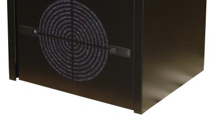
14 6.3 Included Contents (1) P4200W2 Series Air Dryer Package located inside the dryer: (2) Alarm Connector (1) User s Guide (not shown) (1) Mini CD (not shown) (1) Allen Wrench (1) Purge Muffler (1) Compressor Connector Tool (1) Power Cord 6.4 Required Tools and Materials Large adjustable wrench Medium adjustable wrench 7/16 wrench Band cutters or snips Pipe dope or pipe thread tape Cup of soapy water 1-inch paint brush (recommended) Page 14 of 113

15 6.5 Installation Steps Remove all shipping materials. NOTE: If ANY SHIPPING DAMAGE is detected, file a claim with the shipping company prior to continuing the installation procedures Place the dryer at the operating location Remove the Front Panel Check for loose parts, hoses, or wiring. NOTE: If ANY SHIPPING DAMAGE is detected, file a claim with the shipping company prior to continuing the installation procedures. Page 15 of 113


16 6.5.5 Using a 7/16 wrench, remove the shipping block from under the Compressor Plate. Discard block and bolt Remove the ship-loose contents package. On BACK of dryer: Verify that the Red Orifice Plug is still installed where shown Install the Purge Muffler (optional) Verify that the dryer is powered OFF. Page 16 of 113


17 Plug the AC Power Cord into the dryer Plug in or wire the Power Cord to an outlet: VAC power outlet for P4200W2 and P4200W2LP model VAC, 1 phase, power outlet for P4202W2, P4202W2LP, and P4202W2H models Power the dryer ON. NOTE: The Compressor and Heatless Dryer will start, creating air flow through the Red Orifice Plug Set the System Pressure: With Compressor running: Pull the Capacity Control Valve knob out. Page 17 of 113
18 Turn the knob until the reading on the Pressure Gauge is 345 KPa (50 PSI) Push the knob in to lock Let the dryer run until the Humidity drops below 2% (may take up to 15 minutes). NOTE: Press RESET if the dryer goes into SHUTDOWN Power the dryer OFF. Page 18 of 113
19 Remove the Red Orifice Plug from the Outlet Pressure Port. CAUTION: Be careful when removing plug. System may be pressurized Connect the air supply line to the Outlet Pressure Port. PUREGAS recommends using Installation Kit P to connect your air dryer to the air supply line (See section 11.6 for detail) Power the dryer ON Set the Static Pressure: Pull Static Pressure Regulator knob out. Page 19 of 113
20 Turn knob until the reading on the Pressure Gauge is 138 KPa (20 PSI) Push knob in to lock Set the Outlet Pressure: Pull the Outlet Pressure Regulator knob out or loosen the retaining nut (LP models) Turn knob until Outlet Pressure (OUTLET) reading is at the desired setting Push knob in to lock or tighten retaining nut (LP models). Page 20 of 113

21 Check for air leaks: NOTE: This is a general procedure that can be applied to any fitting or hose that has air pressure in it. DO NOT SOAP TEST THE HUMIDITY SENSOR FITTING. DAMAGE TO THE SENSOR MAY OCCUR. With Compressor NOT running: Listen for any hissing sounds which may indicate a fitting or hose air leak. With Compressor running: Use a 1-inch paint brush to dab soapy water on the air fitting or hose connection to be tested. If air bubbles appear at the connection, this indicates that air is leaking from the connection. If any leaks are detected, take steps to seal them off (as necessary): Tighten the fitting Re-connect the hose end Replace the fitting / hose / component Re-install the Front Panel. Page 21 of 113
22 Connect a Common Alarm (as required): Insert the included Alarm Connector into either of the two (2) Alarm Ports Wire an external alarm wire pair to the Alarm Connector as required: Common and N.C. for OPEN ON ALARM operation. Common and N.O. for CLOSE ON ALARM operation REGISTER YOUR DRYER. See section 7 for details. 6.6 Installation Checklist No shipping damage was detected. Dryer location meets the following requirements: o Well ventilated o Free from abrasive dust or chemicals o Ambient temperature is between 5 and 30 C (optimal) Shipping block removed from Compressor Tray. System Pressure is set to 345 KPa (50 PSI). Static Pressure is set to 138 KPa (20 PSI). No air leaks are present in the system. No alarms are present on the Display Panel. Page 22 of 113
23 7. Registering Your Dryer Please take a moment to register your PUREGAS P4200W2 Series Air Dryer. Registering is necessary to activate the Limited Warranty on your product. Once you register, you are eligible to receive free technical support, as well as updates concerning your PUREGAS products. Register Online at Or by Phone (option 2) Have the following information available: Model #: Serial #: Company Name: Location Name: Shipping Address: City: State: Zip Code: Contact Name: Phone #: ( ) - ext. Page 23 of 113
24 8. Operating Your Dryer 8.1 Safety & Warning Information WARNING! Extreme care should be exercised to avoid contact with live electrical circuits. Many procedures performed during installation, operation, testing, and maintenance of this air dryer require the equipment to be running, creating a situation for potential electrical shock. It is highly recommended that you remove all jewelry before performing any procedures. WARNING! Internal surfaces may be hot. Use care when coming into contact with internal components as there is a potential for some of these components to become hot when in operation or standby. WARNING! High Noise. Puregas air dryers are meant to be installed in an unattended area. CAUTION! Observe precautions for handling Electrostatic Sensitive Devices. IMPORTANT! Performing procedures not described in this User s Guide or installing components not supplied by PUREGAS is NOT RECOMMENDED AND MAY VOID THE WARRANTY. Page 24 of 113
. 8.3 Powering the Dryer ON & OFF CAUTION!")
25 8.2 Connecting an Air Line to the Dryer Remove the Red Orifice Plug from the Outlet Pressure Port. CAUTION: Be careful when removing plug. System may be pressurized Connect the air supply line to the Outlet Pressure Port. PUREGAS recommends using Installation Kit P to connect your air dryer to the air supply line (See section 11.6 for detail). 8.3 Powering the Dryer ON & OFF CAUTION! Incoming power to dryer must be: 15 amp service recommended 10 amp slow blow fuse VAC, 50/60 Hz for P4200W2 & P4200W2LP models VAC, 50/60 Hz, 1 Phase for P4202W2, P4202W2LP & P4202W2H models Power Circuit Breaker - Controls the main power to the dryer. Page 25 of 113

26 8.4 Using the Front Panel Display CAUTION! The Display Screen is covered by a clear protective layer that guards against Electrostatic Discharge (ESD). DO NOT REMOVE THIS LAYER ALARM LED Indicates an alarm is present RESET Button Clears an alarm and allows the system to continue operating FUNCTION Button Acts as a HOLD button to freeze the current information screen on the display. When pressed again, it will allow the information screens to begin cycling again. Acts as an ENTER button in the Setup Menu screens Arrow Buttons Used to access, navigate, and change values in the Setup Menu screens. Page 26 of 113

27 8.4.5 Display Screen - Shows the current dryer readings. Will cycle between the following three (3) information screens (unless the HOLD button has been pressed): Sys Status Screen SYS STATUS - Running Status of the system: ONLINE System is Online. SHUTDOWN System has been shutdown as a result of either a High Humidity or High Cabinet Temperature alarm. CAB TEMP Temperature of the dryer cabinet compartment. HUMIDITY Humidity level of the system Outlet Screen OUTLET Outlet Pressure regulated by the Outlet Pressure Regulator. FLOW Air Flow Rate. TANK Air Tank Pressure - fluctuates between KPa. Page 27 of 113


28 Compressor Run Time Screen DUTY CYCLE The percentage of time the Compressor is ON versus time it is OFF during the last Air Tank pressurization cycle. TOTAL How many hours the Compressor has run since the last Compressor Total Time Reset Unit in Standby Screen Occurs when the dryer is connected to a Cycle Kit and has been switched to Standby Mode. Page 28 of 113
 minute, the air dryer will go into SHUTDOWN mode to protect against damage due to overheating.")
29 8.5 Identifying Dryer Alarms High Cabinet Temperature Alarm - Occurs when the temperature in the dryer cabinet (CAB TEMP) rises above 46 C for more than one (1) minute. If the temperature rises above 50 C for more than one (1) minute, the air dryer will go into SHUTDOWN mode to protect against damage due to overheating. This screen will be displayed, showing the Date and Time that the alarm occurred Press the Info ( ) Button to see the detail of the alarm. See section for troubleshooting information High Humidity Alarm Occurs when the Humidity level (HUMIDITY) rises above the alarm threshold for more than one (1) minute. The air dryer will go into SHUTDOWN mode to prevent saturated air from being delivered to the supply line. (Default setting is 10%) This screen will be displayed, showing the Date and Time that the alarm occurred Press the Info ( ) Button to see the detail of the alarm. See section for troubleshooting information. Page 29 of 113
 This screen will be displayed, showing the Date and Time that the alarm occurred. 8.5.3.1 Press the Info ( ) Button to see the detail of the alarm. See section 13.")
30 8.5.3 Low Outlet Pressure Alarm Occurs when the Outlet Pressure (OUTLET) drops below the alarm threshold for more than one (1) minute. (Default setting is 2.0 KPa) This screen will be displayed, showing the Date and Time that the alarm occurred Press the Info ( ) Button to see the detail of the alarm. See section 13.7 for troubleshooting information High Outlet Pressure Alarm - Occurs when the Outlet Pressure (OUTLET) rises above the alarm threshold for more than one (1) minute. (Default setting is KPa) This screen will be displayed, showing the Date and Time that the alarm occurred Press the Info ( ) Button to see the detail of the alarm. See section 13.5 for troubleshooting information. Page 30 of 113
 This screen will be displayed, showing the Date and Time that the alarm occurred. 8.5.5.1 Press the Info ( ) Button to see the detail of the alarm. See section 13.")
31 8.5.5 High Flow Rate Alarm Occurs when the Flow Rate (FLOW) rises above the alarm threshold for more than one (1) minute. (Default setting is 74.0 SCMD) This screen will be displayed, showing the Date and Time that the alarm occurred Press the Info ( ) Button to see the detail of the alarm. See section 13.9 for troubleshooting information High Duty Cycle Alarm Occurs when the Duty Cycle (DUTY CYCLE) exceeds the alarm threshold during the Air Tank pressurization cycle. (Default setting is 70%) This screen will be displayed, showing the Date and Time that the alarm occurred Press the Info ( ) Button to see the detail of the alarm. See section for troubleshooting information. Page 31 of 113
 Button to see the detail of the alarm. See section 10.")
32 8.5.7 Compressor Total Run Time Alarm Occurs when the Compressor has reached an 8,000 Hour maintenance interval. Perform the required maintenance. This screen will be displayed, showing the Date and Time that the alarm occurred Press the Info ( ) Button to see the detail of the alarm. See section 10.3 for maintenance information. Page 32 of 113
33 8.6 Accessing the Setup Menu The P4200W has three (3) Setup sections: System Setup Used to set specific values for the system. Alarm Setup Used to set the alarm thresholds for specific readings. Once the threshold is reached (or exceeded) this results in an alarm. Each of these thresholds is factory programmed with a default value. Many of can be modified to levels based upon your specific application. Network Setup Used to configure network settings including the IP Address, Subnet Mask, Gateway Address, and Keyword. NOTE: Reference Appendix Section 14.2 for Limits, Defaults, and Formats Press the Up ( ) Arrow Button to access the Setup Menu Press the Up ( ) & Down ( ) Arrow Buttons to Select the required menu option Press the Enter ( ) Button to access the menu selected or press the Left ( ) Arrow Button to Escape to the information screens. Page 33 of 113
 8.7.3.1 Press the Enter ( ) Button to access the edit screen. 8.7.3.2 Press the Left ( ) & Right ( ) Arrow Buttons to Select the correct choice (On or Off).")
 Arrow Button to access the next screen. Page 34 of 113")
34 8.7 Using the System Setup Menu In the Setup Menu: Press the Up ( ) & Down ( ) Arrow Buttons to Select the S in System Setup Press the Enter ( ) Button to access System Setup Set Alarm Delay (default setting is ON) Press the Enter ( ) Button to access the edit screen Press the Left ( ) & Right ( ) Arrow Buttons to Select the correct choice (On or Off) Press the Enter ( ) Button to submit the selection Press the Left ( ) & Right ( ) Arrow Buttons to Select the correct confirmation choice (Yes or No) Press the Enter ( ) Button to confirm the selected choice. This will lock in the new setting Press the Up ( ) Arrow Button to access the next screen. Page 34 of 113
 & Right ( ) Arrow Buttons to Select the digit to change. 8.7.5.3 Press the Up ( ) & Down ( ) Arrow Buttons to Change the value of the selected digit.")
 Button to confirm the selected choice. This will lock in the new setting. 8.7.6 Press the Up ( ) Arrow Button to access the next screen.")

35 8.7.5 Set Start Up Delay (default setting is 0 seconds) Press the Enter ( ) Button to access the edit screen Press the Left ( ) & Right ( ) Arrow Buttons to Select the digit to change Press the Up ( ) & Down ( ) Arrow Buttons to Change the value of the selected digit Press the Enter ( ) Button to submit the new setting Press the Left ( ) & Right ( ) Arrow Buttons to Select the correct confirmation choice (Yes or No) Press the Enter ( ) Button to confirm the selected choice. This will lock in the new setting Press the Up ( ) Arrow Button to access the next screen. Page 35 of 113
 Button to confirm the selected choice. This will reset the Total Time to zero (0). 8.7.8 Press the Up ( ) Arrow Button to access the next screen. 8.7.9 Reset To Factory Default Values 8.")
. 8.7.10 Press the Up ( ) Arrow Button to access the next screen. Page 36 of 113")
36 8.7.7 Reset Compressor Total Time Press the Enter ( ) Button to access the reset screen Press the Left ( ) & Right ( ) Arrow Buttons to Select the correct confirmation choice (Yes or No) Press the Enter ( ) Button to confirm the selected choice. This will reset the Total Time to zero (0) Press the Up ( ) Arrow Button to access the next screen Reset To Factory Default Values Press the Enter ( ) Button to access the reset screen Press the Left ( ) & Right ( ) Arrow Buttons to Select the correct confirmation choice (Yes or No) Press the Enter ( ) Button to confirm the selected choice. This will reset all settings to Factory Default Values (section 14.2 ) Press the Up ( ) Arrow Button to access the next screen. Page 36 of 113
 Button to submit the new setting. 8.7.11.5 Press the Left ( ) & Right ( ) Arrow Buttons to Select the correct confirmation choice (Yes or No). 8.7.11.6 Press the Enter ( ) Button to confirm the selected choice.")
37 Set Date / Time Press the Enter ( ) Button to access the edit screen Press the Left ( ) & Right ( ) Arrow Buttons to Select the digit to change Press the Up ( ) & Down ( ) Arrow Buttons to Change the value of the selected digit Press the Enter ( ) Button to submit the new setting Press the Left ( ) & Right ( ) Arrow Buttons to Select the correct confirmation choice (Yes or No) Press the Enter ( ) Button to confirm the selected choice. This will lock in the new setting Press the Up ( ) Arrow Button to access the next screen. Page 37 of 113
 Button to access the edit screen. 8.8.3.2 Press the Left ( ) & Right ( ) Arrow Buttons to select the digit to change. 8.8.3.3 Press the Up ( ) & Down ( ) Arrow Buttons to Change the value of the selected digit.")
 Arrow Button to access the next screen. Page 38 of 113")
38 8.8 Using the Alarm Setup Menu In the Setup Menu: Press the Up ( ) & Down ( ) Arrow Buttons to Select the A in Alarm Setup Press the Enter ( ) Button to access Alarm Setup Set High Humidity Threshold (default setting is 10%) Press the Enter ( ) Button to access the edit screen Press the Left ( ) & Right ( ) Arrow Buttons to select the digit to change Press the Up ( ) & Down ( ) Arrow Buttons to Change the value of the selected digit Press the Enter ( ) Button when to submit the new setting Press the Left ( ) & Right ( ) Arrow Buttons to Select the correct confirmation choice (Yes or No) Press the Enter ( ) Button to confirm the selected choice. This will lock in the new setting Press the Up ( ) Arrow Button to access the next screen. Page 38 of 113
 & Down ( ) Arrow Buttons to Change the value of the selected digit. 8.8.5.4 Press the Enter ( ) Button when to submit the new setting. 8.8.5.5 Press the Left ( ) & Right ( ) Arrow Buttons to Select the correct confirmation choice (Yes or No).")
39 8.8.5 Set High Outlet Threshold (default setting is KPa) Press the Enter ( ) Button to access the edit screen Press the Left ( ) & Right ( ) Arrow Buttons to Select the digit to change Press the Up ( ) & Down ( ) Arrow Buttons to Change the value of the selected digit Press the Enter ( ) Button when to submit the new setting Press the Left ( ) & Right ( ) Arrow Buttons to Select the correct confirmation choice (Yes or No) Press the Enter ( ) Button to confirm the selected choice. This will lock in the new setting Press the Up ( ) Arrow Button to access the next screen. Page 39 of 113
40 8.8.7 Set Low Pressure Threshold (default setting is 2.0 KPa) Press the Enter ( ) Button to access the edit screen Press the Left ( ) & Right ( ) Arrow Buttons to Select the digit to change Press the Up ( ) & Down ( ) Arrow Buttons to Change the value of the selected digit Press the Enter ( ) Button when to submit the new setting Press the Left ( ) & Right ( ) Arrow Buttons to Select the correct confirmation choice (Yes or No) Press the Enter ( ) Button to confirm the selected choice. This will lock in the new setting Press the Up ( ) Arrow Button to access the next screen. Page 40 of 113
 & Down ( ) Arrow Buttons to Change the value of the selected digit. 8.8.9.4 Press the Enter ( ) Button when to submit the new setting. 8.8.9.5 Press the Left ( ) & Right ( ) Arrow Buttons to Select the correct confirmation choice (Yes or No).")
41 8.8.9 Set High Flow Threshold (default setting is 74.0 SCMD) Press the Enter ( ) Button to access the edit screen Press the Left ( ) & Right ( ) Arrow Buttons to Select the digit to change Press the Up ( ) & Down ( ) Arrow Buttons to Change the value of the selected digit Press the Enter ( ) Button when to submit the new setting Press the Left ( ) & Right ( ) Arrow Buttons to Select the correct confirmation choice (Yes or No) Press the Enter ( ) Button to confirm the selected choice. This will lock in the new setting Press the Up ( ) Arrow Button to access the next screen. Page 41 of 113
42 Set High Duty Cycle Threshold (default setting is 70%) Press the Enter ( ) Button to access the edit screen Press the Left ( ) & Right ( ) Arrow Buttons to Select the digit to change Press the Up ( ) & Down ( ) Arrow Buttons to Change the value of the selected digit Press the Enter ( ) Button when to submit the new setting Press the Left ( ) & Right ( ) Arrow Buttons to Select the correct confirmation choice (Yes or No) Press the Enter ( ) Button to confirm the selected choice. This will lock in the new setting Press the Up ( ) Arrow Button to access the next screen. Page 42 of 113
 & Right ( ) Arrow Buttons to Select the digit to change. 8.9.2.2 Press the Up ( ) & Down ( ) Arrow Buttons to Change the value of the selected digit. 8.9.2.3 Press the Enter ( ) Button to submit the Keyword.")
43 8.9 Using the Network Setup Menu In the Setup Menu: Press the Up ( ) & Down ( ) Arrow Buttons to Select the N in Network Setup Press the Enter ( ) Button to access Network Setup Enter Keyword (default Keyword is ) Press the Left ( ) & Right ( ) Arrow Buttons to Select the digit to change Press the Up ( ) & Down ( ) Arrow Buttons to Change the value of the selected digit Press the Enter ( ) Button to submit the Keyword. Page 43 of 113
44 8.9.3 Set IP Address (default is ) Press the Enter ( ) Button to access the edit screen Press the Left ( ) & Right ( ) Arrow Buttons to Select the digit to change Press the Up ( ) & Down ( ) Arrow Buttons to Change the value of the selected digit Press the Enter ( ) Button when to submit the new setting Press the Left ( ) & Right ( ) Arrow Buttons to Select the correct confirmation choice (Yes or No) Press the Enter ( ) Button to confirm the selected choice. This will lock in the new setting Press the Up ( ) Arrow Button to access the next screen. Page 44 of 113
45 8.9.5 Set Subnet Mask (default is ) Press the Enter ( ) Button to access the edit screen Press the Left ( ) & Right ( ) Arrow Buttons to Select the digit to change Press the Up ( ) & Down ( ) Arrow Buttons to Change the value of the selected digit Press the Enter ( ) Button when to submit the new setting Press the Left ( ) & Right ( ) Arrow Buttons to Select the correct confirmation choice (Yes or No) Press the Enter ( ) Button to confirm the selected choice. This will lock in the new setting Press the Up ( ) Arrow Button to access the next screen. Page 45 of 113
 & Down ( ) Arrow Buttons to Change the value of the selected digit. 8.9.7.4 Press the Enter ( ) Button when to submit the new setting. 8.9.7.5 Press the Left ( ) & Right ( ) Arrow Buttons to Select the correct confirmation choice (Yes or No).")
46 8.9.7 Set Gateway Address (default is ) Press the Enter ( ) Button to access the edit screen Press the Left ( ) & Right ( ) Arrow Buttons to Select the digit to change Press the Up ( ) & Down ( ) Arrow Buttons to Change the value of the selected digit Press the Enter ( ) Button when to submit the new setting Press the Left ( ) & Right ( ) Arrow Buttons to Select the correct confirmation choice (Yes or No) Press the Enter ( ) Button to confirm the selected choice. This will lock in the new setting Press the Up ( ) Arrow Button to access the next screen. Page 46 of 113
 Button when to submit the new setting. 8.9.9.5 Press the Left ( ) & Right ( ) Arrow Buttons to Select the correct confirmation choice (Yes or No). 8.9.9.6 Press the Enter ( ) Button to confirm the selected choice.")
47 8.9.9 Change Keyword (default is ) Press the Enter ( ) Button to access the edit screen Press the Left ( ) & Right ( ) Arrow Buttons to Select the digit to change Press the Up ( ) & Down ( ) Arrow Buttons to Change the value of the selected digit Press the Enter ( ) Button when to submit the new setting Press the Left ( ) & Right ( ) Arrow Buttons to Select the correct confirmation choice (Yes or No) Press the Enter ( ) Button to confirm the selected choice. This will lock in the new setting. Page 47 of 113
 Trigger Latches. 8.11.3 Lift the Top Cover off of the dryer. NOTE: There is a wire connected between the Top Cover and the dryer s main frame.")
48 8.10 Removing the Front Panel Depress the four (4) Trigger Latches Pull the Front Panel away from the dryer Removing the Top Cover Use he included Allen Wrench to unlock the two (2) Trigger Latches Depress the two (2) Trigger Latches Lift the Top Cover off of the dryer. NOTE: There is a wire connected between the Top Cover and the dryer s main frame. This is used for grounding purposes. Page 48 of 113
. 8.12.3 Reinstall the Front Panel (section 8.10 ). 8.13")
49 8.12 Depressurizing the Dryer Remove the Front Panel (section 8.10 ) Pull the ring handle on the Safety Relief Valve until all air pressure is released. NOTE: To prevent pressure from building back up, power the dryer OFF (section 8.3 ) Reinstall the Front Panel (section 8.10 ) Connecting to Common Alarm Socket Insert the included Alarm Connector into either of the two (2) Alarm Ports Wire an external alarm wire pair to the Alarm Connector as required: Common and N.C. for OPEN ON ALARM operation. Common and N.O. for CLOSE ON ALARM operation. Page 49 of 113
50 8.14 Setting the System Pressure Remove the Front Panel (section 8.10 ). With Compressor running: Pull the Capacity Control Valve knob out Turn the knob until the reading on the Pressure Gauge is 345 KPa (50 PSI) Push the knob in to lock Reinstall the Front Panel (section 8.10 ). Page 50 of 113
. Page 51 of 113")
51 8.15 Setting the Static Pressure Remove the Front Panel (section 8.10 ) Pull the Static Pressure Regulator knob out Turn knob until the reading on the Pressure Gauge is 138 KPa (20 PSI) Push knob in to lock Reinstall the Front Panel (section 8.10 ). Page 51 of 113
52 8.16 Setting the Outlet Pressure Remove the Front Panel (section 8.10 ) Pull the Outlet Pressure Regulator knob out Turn knob until Outlet Pressure (OUTLET) reading is at the desired setting Push knob in to lock Reinstall the Front Panel (section 8.10 ). Page 52 of 113
 or Mozilla Firefox Web Browser.")
53 8.17 Connecting via Web Browser If the Air Dryer IS connected to an IP network: The Air Dryer must be configured with a valid IP Address, Subnet Mask, and Gateway Address for the network. An IP cable must be connecting the air dryer to the network. Use a computer that is on the same network as the air dryer. Use Internet Explorer (6.0 or newer) or Mozilla Firefox Web Browser. If the Air Dryer IS NOT connected to an IP network and has not been configured with IP information: Use the default IP Address ( ) of the air dryer to connect. Use an IP Cable (may require Cross-over cable) plugged directly into a Laptop/PC and the other end plugged into the Network Port of the air dryer. Configure the network card on the Laptop/PC to use the IP Address This will make the Laptop/PC compatible with the air dryer. Use Internet Explorer (6.0 or newer) or Mozilla Firefox Web Browser Type the IP Address of the P4200W2 Series Air Dryer in the Address text box of the Web Browser. Page 53 of 113

54 The Web Browser connection offers five (5) screens to the user: Status Screen - Displays the readings and alarms monitored in the P4200W2 Series Air Dryer. Provides remote ALARM RESET. Setup Screen - All configurations for System, Alarms, Network, and Keyword can be made in this screen. Event Screen - Displays all events such as alarms, changes made, and alarm resets registered by the P4200W2 Series Air Dryer. This screen is informational only. Alarm Screen - Displays all the Alarms registered by the P4200W2 Series Air Dryer. This screen is informational only. Firmware Screen Allows the user to upload any software updates or upgrades to the Air Dryer Click on the Menu Bar selection to access a specific screen. Page 54 of 113


55 8.18 Using the Status Screen Displays the readings and alarms monitored in the P4200W2 Series Air Dryer. Provides remote ALARM RESET. Readings are displayed in BLACK unless an alarm is present. Alarms are displayed in RED next to the parameter in alarm. Alarm Status will display ALARM if any alarms are present. Keyword validation is required for ALARM RESET and RESET COMPRESSOR TOTAL RUN TIME. Page 55 of 113
 8.18.1.3 Click on SUBMIT Button when done. Page 56 of 113")
56 Resetting an Alarm Click on the ALARM RESET Button to remotely reset Air Dryer alarms displayed on Status Screen Enter Keyword (default is ) Click on SUBMIT Button when done. Page 56 of 113
 8.18.2.3 Click on SUBMIT Button when done. Page 57 of 113")
57 Resetting a Compressor Total Run Time Click on the RESET COMPRESSOR TOTAL RUN TIME Button to remotely reset Compressor Total Run Time displayed on Status Screen Enter Keyword (default is ) Click on SUBMIT Button when done. Page 57 of 113
58 8.19 Using the Setup Screen All configurations for the System, Alarms, Network, and Keyword can be made in this screen. Values in BLUE represent the current setting. The ENTER Button is used to change values. The CHANGE KEYWORD Button allows you to configure a new Keyword. Keyword validation is required for the following: o Changing a Threshold value o Changing the Keyword Page 58 of 113
 8.19.1.5 Click on SUBMIT Button when done. This will lock in the new setting value. Page 59 of 113")
59 Changing a Threshold or Setup value: Click on the value to change Type in the new value Click the ENTER Button when done Enter Keyword (default is ) Click on SUBMIT Button when done. This will lock in the new setting value. Page 59 of 113


60 Changing the Keyword Click on CHANGE KEYWORD Button to change the keyword Type the Old Keyword Type the New Keyword Type the Confirm New Keyword Click on SUBMIT Button to confirm. This will lock in the new setting value. Page 60 of 113

61 8.20 Using the Event Screen Displays all events such as alarms, changes made, and alarm resets registered by the P4200W2 Series Air Dryer. This screen is informational only. Click on the column headings to sort data according to that column. Click the Arrow Buttons to navigate through all the event log pages. Page 61 of 113

62 8.21 Using the Alarm Screen Displays all the Alarms registered by the P4200W2 Series Air Dryer. This screen is informational only. Click on the column headings to sort data according to that column. Click the Arrow Buttons to navigate through all the event log pages. Page 62 of 113
63 8.22 Using the Firmware Screen Displays the current firmware version and date of the P4200W2 Series Air Dryer. Current Version: Displays the current firmware version of the P4200W2 Series Air Dryer. New Version File: Displays the new location and new firmware version chosen. The BROWSE Button allows you to locate the new firmware file. The ACCEPT Button is used to change values. Keyword validation is required to update firmware. Page 63 of 113
 8.22.1.5 Click on SUBMIT Button when done. This will lock in the new firmware version. Page 64 of 113")
64 Updating the Firmware: Click on BROWSE Button to locate the firmware file Navigate and select the correct.bin file. Press the OK Button Click the ENTER Button Enter Keyword (default is ) Click on SUBMIT Button when done. This will lock in the new firmware version. Page 64 of 113
65 8.23 Connecting via SNMP Using SNMP to connect and communicate with the P4200W2 Series Air Dryer is dependant upon the specific SNMP Management software used on your network. This software requires a SNMP Definition & Configuration File (MIB file) in order to properly communicate with the Air Dryer. This file is named PuregasP4200W2.mib and is located on the Mini CD included with your Air Dryer. It is necessary to import this file into your SNMP operating software. NOTE: Reference Appendix section 14.3 for a list of SNMP Parameters. Page 65 of 113
66 9. Testing Your Dryer 9.1 Safety & Warning Information WARNING! Extreme care should be exercised to avoid contact with live electrical circuits. Many procedures performed during installation, operation, testing, and maintenance of this air dryer require the equipment to be running, creating a situation for potential electrical shock. It is highly recommended that you remove all jewelry before performing any procedures. WARNING! Internal surfaces may be hot. Use care when coming into contact with internal components as there is a potential for some of these components to become hot when in operation or standby. WARNING! High Noise. Puregas air dryers are meant to be installed in an unattended area. CAUTION! Observe precautions for handling Electrostatic Sensitive Devices. CAUTION! Depressurizing the air dryer may be necessary before performing certain procedures. NEVER remove pressure sensing tubes from the control board without depressurizing the air dryer first, or damage to the control board will occur. Page 66 of 113
.")

67 9.2 Measuring Compressor Amp Draw WARNING! Internal surfaces may be hot. Use care when coming into contact with internal components as there is a potential for some these components to become hot when in operation or standby Remove the Front Panel (section 8.10 ). With the Compressor running: Locate the BLACK wire coming directly from the Compressor Use an Amp Meter to measure the Amps of the BLACK wire. With the Compressor running, the running amps should measure: 8.6 amps or below for the P4200W2 & P4200W2LP models. 3.9 or below for the P4202W2 & P4202W2LP models. 4.2 or below for the P4202W2H model. If the Compressor measures over the recommended running amps, see section for troubleshooting information Reinstall the Front Panel (section 8.10 ). Page 67 of 113
. With the Compressor running: 9.3.2 Locate the Compressor power connector.")
68 9.3 Measuring Voltage to Compressor WARNING! Extreme care should be exercised to avoid contact with live electrical circuits. It is highly recommended that you remove all jewelry before performing any procedures Remove the Front Panel (section 8.10 ). With the Compressor running: Locate the Compressor power connector Use a Voltmeter to measure the voltage between the BLACK and WHITE wires: Place the Voltmeter probes in the openings in the power connector. The voltage should measure: VAC for the P4200W2 & P4200W2LP models VAC for the P4202W2, P4202W2LP & P4202W2H models Reinstall the Front Panel (section 8.10 ). Page 68 of 113
. 9.4.2 Locate the Power Line Filter inside the Top Section of the air dryer.")
69 9.4 Measuring Voltage at the Power Line Filter WARNING! Extreme care should be exercised to avoid contact with live electrical circuits. It is highly recommended that you remove all jewelry before performing any procedures Remove the Top Cover (section 8.11 ) Locate the Power Line Filter inside the Top Section of the air dryer Use a Voltmeter to measure the voltage: Place the probes between the Power Line Filter and terminal insulation so that they touch the metal contacts. The voltage should measure: VAC for the P4200W2 & P4200W2LP models VAC for the P4202W2, P4202W2LP & P4202W2H models. If any of the voltage measurements are different than indicated above, the Power Line Filter is defective and should be replaced. See sections 11.1 for part detail and 11.7 for ordering information Reinstall the Top Cover (section 8.11 ). Page 69 of 113
. 9.5.2 Locate the Power IEC Connector inside the Top Section of the air dryer.")

70 9.5 Measuring Incoming Voltage WARNING! Extreme care should be exercised to avoid contact with live electrical circuits. It is highly recommended that you remove all jewelry before performing any procedures Remove the Top Cover (section 8.11 ) Locate the Power IEC Connector inside the Top Section of the air dryer Use a Voltmeter to measure the voltage: Place the probes between the IEC Connector and terminal insulation so that they touch the metal contacts. The voltage should measure: VAC for the P4200W2 & P4200W2LP models VAC for the P4202W2, P4202W2LP & P4202W2H models. If the incoming voltage measures less than indicated above, it is recommended that steps be taken at your facility to increase the incoming power to the recommended levels Reinstall the Top Cover (section 8.11 ). Page 70 of 113
71 9.6 Measuring Voltages at Solid State Relay Remove the Top Cover (section 8.11 ) Locate the Solid State Relay inside the Top Section of the air dryer. With the Compressor running: Use a Voltmeter to measure across the AC terminals. The voltage should measure 0 VAC Use a Voltmeter to measure across the DC terminals. The voltage should measure: 5 VDC for the P4200W2 & P4200W2LP models. 12 VDC for the P4202W2, P4202W2LP & P4202W2H models. Page 71 of 113
.")
72 With the Compressor NOT running: Use a Voltmeter to measure across the AC terminals. The voltage should measure: VAC for the P4200W2 & P4200W2LP models VAC for the P4202W2, P4202W2LP & P4202W2H models Use a Voltmeter to measure across the DC terminals. The voltage should measure 0 VDC Reinstall the Top Cover (section 8.11 ). If any of the voltage measurements are different than indicated above, the Solid State Relay is defective and should be replaced. See sections 11.1 for part detail and 11.7 for ordering information. Page 72 of 113

.")
73 9.7 Testing Consistent Heatless Dryer Cycling Remove the Front Panel (section 8.10 ). With the Compressor running: Disconnect the purge tubes from the Heatless Dryer Place your hand beneath the purge fittings to feel for purging air. Air should: Purge from Tower 1 side Purge from Tower 2 side 30 Seconds later Purge from Tower 1 side 30 Seconds later and so on Re-connect the purge tubes to the Heatless Dryer Reinstall the Front Panel (section 8.10 ). If the Heatless Dryer is not cycling consistently as described, see section for troubleshooting information. Page 73 of 113


74 9.8 Testing Unloader Valve Remove the Front Panel (section 8.10 ). With the Compressor running: Disconnect the Unloader tube from the Unloader Valve Place your hand beneath the Unloader Valve fitting to feel for air flow. Air should NOT flow from this fitting continuously. Air should only be released in a short burst when the Compressor shuts off Re-connect the Unloader tube to the Unloader Valve Reinstall the Front Panel (section 8.10 ). If air flows from this valve continuously the Unloader Valve is defective and should be replaced. See sections 11.4 for part detail and 11.7 for ordering information. Page 74 of 113
 sets of terminals (from left-to-right): VALVE Left solenoid IN Incoming power VALVE Right solenoid 9.")
75 9.9 Measuring Heatless Dryer Solenoid Voltage Remove the Front Panel (section 8.10 ). With the Compressor running: Locate the Heatless Dryer Cycle Timer. The timer has three (3) sets of terminals (from left-to-right): VALVE Left solenoid IN Incoming power VALVE Right solenoid Use a Voltmeter to measure the DC voltage across each set of VALVE terminals. Continue to measure for up to 45 seconds if no voltage is initially measured. The voltage should measure: 53 VDC for the P4200W2 & P4200W2LP models. 106 VDC for the P4202W2, P4202W2LP & P4202W2H models Reinstall the Front Panel (section 8.10 ). If the voltage does not measure as indicated above, this is an indication that the Cycle Timer is defective and should be replaced. See sections 11.4 for part detail and 11.7 for ordering information Page 75 of 113
 Replace defective fan (see sections 11.3 for part detail and 11.7 for ordering information). 9.11 Testing Safety Relief Valve 9.11.1 Remove the Front Panel (section 8.")
76 9.10 Testing Precooler Fan Place your hand in front of the Precooler Fan to feel for air being blown outward. If the fan is not blowing air outward as described: Check for loose wiring. Refer to the Wiring Diagram (section 14.1 ) Replace defective fan (see sections 11.3 for part detail and 11.7 for ordering information) Testing Safety Relief Valve Remove the Front Panel (section 8.10 ) Pull the ring handle on the Safety Relief Valve to verify air pressure is released Release ring handle and verify that no air is leaking from the valve Reinstall the Front Panel (section 8.10 ). If the Safety Relief Valve fails either test described, it must be replaced. See sections 11.3 for part detail and 11.7 for ordering information. Page 76 of 113
 appears on the display, press the HOLD Button on the Front Panel to freeze that screen. With Compressor running: 9.12.")
77 9.12 Testing Compressor ON/OFF Cycling Remove the Front Panel (section 8.10 ) When the Outlet Screen (section ) appears on the display, press the HOLD Button on the Front Panel to freeze that screen. With Compressor running: Verify the Compressor shuts down when the Tank Pressure (TANK) reaches 345 KPa. If the Tank Pressure (TANK) fails to reach 345 KPa, see section for troubleshooting information. With Compressor NOT running: Pull the ring handle on the Safety Relief Valve to release air pressure from the Air Tank Verify the Compressor turns on when the Tank Pressure (TANK) falls to 172 KPa Reinstall the Front Panel (section 8.10 ). If the Compressor Cycling fails either test described, it indicates a problem with the Control Board which may need to be replaced. See sections 11.1 for part detail and 11.7 for ordering information. Page 77 of 113
78 9.13 Testing High Duty Cycle Alarm NOTE: For this test, allow the Display Screen to cycle through the information screens Remove the Front Panel (section 8.10 ) Allow the Compressor run and then turn off Immediately after the Compressor turns off, pull the ring handle on the Safety Relief Valve until the Compressor turns on again. A High Duty Cycle Alarm should appear on the Display Screen Allow the Compressor to turn off Press the RESET Button to clear the alarm Reinstall the Front Panel (section 8.10 ). If you are unable to create a High Duty Cycle Alarm as described, see section for troubleshooting information. Page 78 of 113
79 9.14 Testing Humidity Alarm and System Shutdown Power the air dryer OFF Remove the Front Panel (section 8.10 ) Depressurize the air dryer Unscrew and remove the Humitter from the Combo Block Power the air dryer ON. Page 79 of 113
80 Allow the Humidity reading to rise over 10.0% After three (3) minutes, verify that a Humidity Alarm appears and the dryer goes into SHUTDOWN mode Replace the Humitter into the Combo Block Press the RESET Button to clear the alarm Reinstall the Front Panel (section 8.10 ). NOTE: If the Humitter is disconnected from the Control Board, **% will appear on the Humidity reading and after 5 minutes the unit will Shutdown. This is to allow for troubleshooting. If you are unable to create a Humidity / Shutdown alarm as described, see section for troubleshooting information. Page 80 of 113
 reading climbs over the alarm threshold. (section 8.8.5 ) 9.15.5 After one (1) minute, verify that a High Outlet Pressure Alarm appears on the display.")
81 9.15 Testing High Outlet Pressure Alarm Make a note of the current Outlet Pressure (OUTLET) reading Remove the Front Panel (section 8.10 ). With Compressor running: Pull the Outlet Pressure Regulator knob out Turn knob clockwise until Outlet Pressure (OUTLET) reading climbs over the alarm threshold. (section ) After one (1) minute, verify that a High Outlet Pressure Alarm appears on the display Press the RESET Button to clear the alarm. Page 81 of 113
82 Turn Outlet Pressure Regulator knob counterclockwise until Outlet Pressure (OUTLET) reading lowers to the reading recorded in step Push knob in to lock Reinstall the Front Panel (section 8.10 ). If you are unable to create a High Outlet Pressure Alarm as described, see section 13.6 for troubleshooting information Testing Low Outlet Pressure Alarm Make a note of the current Outlet Pressure (OUTLET) reading Remove the Front Panel (section 8.10 ). With Compressor running: Pull the Outlet Pressure Regulator knob out Turn knob counterclockwise until Outlet Pressure (OUTLET) reading drops below the alarm threshold. (section ) Page 82 of 113
83 After one (1) minute, verify that a Low Outlet Pressure Alarm appears on the display Press the RESET Button to clear the alarm Turn Outlet Pressure Regulator knob clockwise until Outlet Pressure (OUTLET) reading raises to the reading recorded in step Push knob in to lock Reinstall the Front Panel (section 8.10 ). If you are unable to create a Low Outlet Pressure Alarm as described, see section 13.8 for troubleshooting information. Page 83 of 113
84 9.17 Testing Air Fittings & Hoses for Leaks NOTE: This is a general procedure that can be applied to any fitting or hose that has air pressure in it. DO NOT SOAP TEST THE HUMIDITY SENSOR FITTING. DAMAGE TO THE SENSOR MAY OCCUR. With Compressor NOT running: Listen for any hissing sounds which may indicate a fitting or hose air leak. With Compressor running: Use a 1-inch paint brush to dab soapy water on the air fitting or hose connection to be tested. If air bubbles appear at the connection, this indicates that air is leaking from the connection. If any leaks are detected, take steps to seal them off (as necessary): Tighten the fitting Re-connect the hose end Replace the fitting / hose / component Page 84 of 113
85 10. Maintaining Your Dryer In order to ensure that your P4200W2 Series Air Dryer continues to operate efficiently and reliably, PUREGAS recommends performing the following maintenance procedures at the specified Six Month and 8,000 Hour intervals. It is also recommended that you print out the included Six Month Maintenance (section 10.2 ) and 8,000 Hour Maintenance (section 10.3 ) log sheets and record all completed maintenance for historical tracking and reference purposes. The log sheets include a Section reference column which indicates the User s Guide section containing the information about the specific procedure. Please refer to these sections for detailed procedural information. NOTE: When operating at higher ambient temperatures, it is recommended that maintenance be performed more frequently. NOTE: After 16,000 hours of run time, PUREGAS recommends sending in your Compressor and Heatless Dryer for a complete and comprehensive rebuild by our Service Department technicians. See sections 12.1 and 12.2 for information on services and contacting PUREGAS Safety & Warning Information WARNING! Extreme care should be exercised to avoid contact with live electrical circuits. Many procedures performed during installation, operation, testing, and maintenance of this air dryer require the equipment to be running, creating a situation for potential electrical shock. It is highly recommended that you remove all jewelry before performing any procedures. Page 85 of 113
86 WARNING! Internal surfaces may be hot. Use care when coming into contact with internal components as there is a potential for some of these components to become hot when in operation or standby. CAUTION! SHUT DOWN IMMEDIATELY FOR REPAIRS if the air compressor shows any evidence of overheating or presents excessive noise. CAUTION! Depressurizing the air dryer may be necessary before performing certain procedures. NEVER remove pressure sensing tubes from the Control Board without depressurizing the air dryer first, or damage to the Control Board will occur. WARNING! High Noise. Puregas air dryers are meant to be installed in an unattended area. CAUTION! Observe precautions for handling Electrostatic Sensitive Devices. IMPORTANT! After performing any maintenance, always soap test pressure fittings to check for air leaks. Also, check for any loose or disconnected wiring. Page 86 of 113
87 10.2 Six Month Maintenance MODEL: LOCATION NAME: SERIAL NUMBER: ADDRESS: DATE INSTALLED: Maintenance Interval (Months) Procedure Section Install Six Month Maintenance Kit P Install P for P4202W2H ONLY 11.6 Read & Record Flow Rate (FLOW) Measure & Record Compressor Amp Draw 9.2 Measure & Record Incoming Voltage 9.5 Test High & Low Outlet Pressure Alarms 9.15 & 9.16 Set System Pressure (345 KPa / 50 PSI) 8.14 Set Static Pressure (138 KPa / 20 PSI) 8.15 Set Outlet Pressure 8.16 Test Consistent Heatless Dryer Cycling 9.7 Test Precooler Fan 9.10 Test Safety Relief Valve 9.11 Test Compressor ON/OFF Cycling 9.12 Test Duty Cycle Alarm 9.13 Test Humidity Alarm & System Shutdown 9.14 Test Air Fittings and Hoses for Leaks 9.17 Clean Precooler Coils Visually Inspect Inside & Outside of Unit for Loose Wiring or Hardware Maintenance Performed by: Date of Maintenance: NOTE: COPY OR PRINT THIS PAGE AND KEEP IT WITH THE AIR DRYER Page 87 of 113
88 10.3 8,000 Hour Maintenance Under typical operating conditions: 8,000 hours of run time will occur between one (1) and two (2) years of use. This will be identified by a COMPERSSOR RUN TIME: TOTAL Alarm on the display. MODEL: LOCATION NAME: SERIAL NUMBER: ADDRESS: DATE INSTALLED: Maintenance Interval (Hours) Procedure Section 8,000 16,000 24,000 32,000 40,000 Install 8,000 Hour Maintenance Kit P Install P for P4202W2H ONLY 11.6 Read & Record Flow Rate (FLOW) Measure & Record Compressor Amp Draw 9.2 Set System Pressure (345 KPa / 50 PSI) 8.14 Set Static Pressure (138 KPa / 20 PSI) 8.15 Set Outlet Pressure 8.16 Test Consistent Heatless Dryer Cycling 9.7 Test Compressor ON/OFF Cycling 9.12 Test Air Fittings and Hoses for Leaks 9.17 Reset COMPRESOR TOTAL RUN TIME Reading to Zero Visually Inspect Inside & Outside of Unit for Loose Wiring or Hardware Maintenance Performed by: Date of Maintenance: NOTE: COPY OR PRINT THIS PAGE AND KEEP IT WITH THE AIR DRYER Page 88 of 113

 Control Board P012304 1 (1) Varistor P012033 P012034 1 (1) Solid")
89 11. Replacement Parts & Accessories 11.1 Top Section Parts Description Part Number Quantity Recommend Spare P4200W2 P4202W2 P4200W2LP P4202W2LP (120 VAC) P4202W2H (220 VAC) Power IEC Connector P Power Line Filter P Circuit Breaker P (1) Control Board P (1) Varistor P P (1) Solid State Relay P (1) Front Panel Display P Page 89 of 113
 P4202W2 P4202W2LP P4202W2H (220 VAC) Precooler")
 P013339 1 Humitter P011380 1")

90 11.2 Middle & Lower Section Parts 1 Description Part Number Quantity Recommend Spare P4200W2 P4200W2LP (120 VAC) P4202W2 P4202W2LP P4202W2H (220 VAC) Precooler P Heatless Dryer Assembly See section 11.4 for detail Static Pressure Gauge (0-30 PSI) P Humitter P Temperature Sensor P Compressor Air Intake Filter In Kit P See section 11.6 for detail In Kit P for P4202W2H ONLY Outlet Pressure Regulator (Low Pressure) P (P012316) 1 (1) (1) Page 90 of 113
 Flow Block 1 Compressor P013261 P013262 P012518 (1) Vibration Mounts P4582S 4 Safety Relief Valve P03646 1 Page 91")
91 11.3 Middle & Lower Section Parts 2 Recommend Description Part Number Quantity Spare P4200W2 & P4200W2LP (120 VAC) P4202W2 & P4202W2LP (220 VAC) P4202W2H (220VAC) Fan P P Static Pressure Regulator P (1) Flow Block 1 Compressor P P P (1) Vibration Mounts P4582S 4 Safety Relief Valve P Page 91 of 113
 (120 VAC)")
 Pressure Gauge (0 100 PSI) P010695 1 Cycle")
 Solenoid Valve In Kit P011471. See section 11.")
92 11.4 Heatless Dryer Assembly Parts Description Part Number Quantity Recommend Spare P4200W2 & P4200W2LP P4202W2 & P4202W2LP P4202W2H (220 VAC) (120 VAC) (220 VAC) Heatless Dryer Assembly PHF2C PHF2C PHF2C Capacity Control Valve P (1) Pressure Gauge (0 100 PSI) P Cycle Timer P010530F1 P010530F2 1 Desiccant Chamber P Unloader Valve P P (1) Solenoid Valve In Kit P See section 11.6 for detail. Page 92 of 113


93 11.5 Frame Section Parts Description Part Number Quantity Recommend Spare Front Panel 1 Trigger Latch 6 Air Intake Filter In Kit P See section 11.6 for detail. In Kit P for P4202W2H ONLY Top Cover 1 Fan Guard P Purge Muffler In Kit P See section 11.6 for detail In Kit P for P4202W2H ONLY Page 93 of 113

 (1) Cycle Kit Interface Kit P012341 1/2 Bleed Orifice Kit")
94 11.6 Accessories for Your Dryer Description Installation Kit Includes fittings required to connect to 3/4 flexible hose or 1/2 tubing. Six Month Maintenance Kit Includes air intake filter, compressor air intake filter, and purge muffler. 8,000 Hour Maintenance Kit Includes heatless dryer maintenance kit and compressor maintenance kit. Cycle Kit Allows multiple dryers to be cycled. Part Number P P P4202W2H = P P P4202W2H = P P08033W Recomme nd Spare (2) (1) Cycle Kit Interface Kit P /2 Bleed Orifice Kit Allows the Compressor and Heatless Dryer to cycle in low flow applications. P Page 94 of 113
P550W Series Air Dryers
 P550W Series Air Dryers User s Guide Models covered: P550W P550WH P550WLP P552W P552WH P552WLP 1. Welcome & Congratulations Congratulations on your purchase of a new PUREGAS P550W Series Air Dryer! We
P6500W Air Dryer User s Guide
 P6500W Air Dryer User s Guide 1. Welcome & Congratulations Congratulations on your purchase of a new PUREGAS P6500W Air Dryer! We here at PUREGAS are very proud of our products and we are committed to
P4200PM / P5000PM Remote Air Dryer User s Guide
 P4200PM / P5000PM Remote Air Dryer User s Guide 1. Welcome & Congratulations Congratulations on your purchase of a new PUREGAS P4200PM / P5000PM Air Dryer! We here at PUREGAS are very proud of our products
Installation Guide. P1500W Series Air Dryer
 P1500W Series Air Dryer Installation Guide This guide covers basic air dryer installation and setup only. Once installation is complete, please refer to the P1500W Series User s Guide for more advanced
P10KW / P15KW Air Dryer Installation Guide
 P10KW / P15KW Air Dryer Installation Guide This guide covers basic air dryer installation and setup only. Once installation is complete, please refer to the P10KW / P15KW User s Guide for more advanced
VSA Series Air Dryer. User s Guide
 VSA Series Air Dryer User s Guide Models covered: VSA1 VSA2 VSA3 VSA4 1. Welcome & Congratulations Congratulations on your purchase of a new PUREGAS VSA SERIES AIR DRYER! We here at PUREGAS are very proud
MDH Series Air Dryer. User s Guide
 MDH Series Air Dryer User s Guide Models covered: MDH1 MDH2 MDH3 MDH4 MDH5 MDH6 1. Welcome & Congratulations Congratulations on your purchase of a new PUREGAS MDH SERIES AIR DRYER! We here at PUREGAS
P08033W Air Dryer Cycling Module User s Guide
 P08033W Air Dryer Cycling Module User s Guide 1. Welcome & Congratulations Congratulations on your purchase of a new PUREGAS P08033W Air Dryer Cycling Module! We here at PUREGAS are very proud of our
Operating & Maintenance Manual. Alert-4 Ethernet LCD Master Alarm
 Operating & Maintenance Manual Alert-4 Ethernet LCD Master Alarm w w w. a m i c o. c o m Contents User Responsibility 4 Introduction 4 Features 5 Description of the Alarm 5 Shipment Details 5 The Alarm
OPERATING MANUAL MODEL AIR 1500TM AIR DRYER
 OPERATING MANUAL MODEL AIR 500TM AIR DRYER Puregas, LLC 226-A Commerce St. Tel: 800-52-535 Broomfield, Colorado Fax: 303-657-2205 P/N P0255 REV A, 02/9/4 TABLE OF CONTENTS.0 GENERAL... 3 2.0 SPECIFICATIONS...
MODEL MW200 MODEL MW600 AIR DRYER
 OPERATING MANUAL MODEL MW200 MODEL MW600 AIR DRYER Mail Address: 226A Commerce St. Tel: 303-465-3063 Broomfield, CO 80020 Fax: 303-465-9294 TABLE OF CONTENTS 1.0 GENERAL...3 2.0 SPECIFICATIONS...3 3.0
WILKERSON MODELS DE3, DE4 AND DE5 COMPACT HEATLESS AIR DRYERS
 INSTRUCTION MANUAL FOR WILKERSON MODELS DE3, DE4 AND DE5 COMPACT HEATLESS AIR DRYERS DE3 - DE5 OPERATIONS GENERAL This instruction manual covers the installation, operation, maintenance and troubleshooting
Remote Vacuum Sensor and Variable Speed Vacuum Pump Control Manual. Version Date - June Part Number
 Innovation In and Out of Parlour Remote Vacuum Sensor and Variable Speed Vacuum Pump Control Manual Version - 1.0 Date - June 2016 Part Number - 39-0038 Index Manual Version... 3 About the Remote Vacuum
THX-DL Data Logger USER & INSTALLATION MANUAL V
 THX-DL Data Logger USER & INSTALLATION MANUAL V1.2012 www.thermomax-refrigeration.com Contents PRESENTATION Summary of Features 2 INSTALLATION Safety Precautions 4 THX Unit 4 Sensors 4 Alarm Relay 4 Power
OWNER S MANUAL AVN SERIES RETRACTABLE NOZZLE VACUUM SEALER WITH GAS PURGE
 OWNER S MANUAL AVN SERIES RETRACTABLE NOZZLE VACUUM SEALER WITH GAS PURGE WHAT S IN THE PACKAGE? This Operation Manual. (1) Vacuum Sealer. (1) E-(unit size) Heating Element, inside the manual sheet protector.
PMT200A SERIES DEHYDRATOR USER MANUAL. Bulletin AE01B-A NOV 05
 PMT200A SERIES DEHYDRATOR USER MANUAL Bulletin AE01B-A0523-001 Rev: B 18 NOV 05 1 TABLE OF CONTENTS SECTION 1 General Information 3 Introduction 3 Description 3 Operation 3 Alarm 3 Multiple Alarm Option
OWNER S MANUAL CAVN SERIES SELF CONTAINED RETRACTABLE NOZZLE VACUUM SEALER WITH GAS PURGE
 OWNER S MANUAL CAVN SERIES SELF CONTAINED RETRACTABLE NOZZLE VACUUM SEALER WITH GAS PURGE WHAT S IN THE PACKAGE? This Operation Manual. (1) Vacuum Sealer. (1) E-(unit size) Heating Element, inside the
Installation & Maintenance Instructions. Smart Guard Ultra ZERO AIR LOSS CONDENSATE DRAIN 02/09
 Installation & Maintenance Instructions Smart Guard Ultra ZERO AIR LOSS CONDENSATE DRAIN 02/09 GENERAL OPERATION The Smart Guard Ultra is a zero-air-loss, electronic level sensing condensate drain. By
Operating & Maintenance Manual. Alert-4 Ethernet LCD Master Alarm
 Operating & Maintenance Manual Alert-4 Ethernet LCD Master Alarm Contents User Responsibility 4 Introduction 4 Features 5 Description of the Alarm 5 Shipment Details 5 The Alarm Back Box 5 The Frame/Module
Operations Manual TS400. Test Station for G450/G460 Gas Detector
 TS400 Test Station for G450/G460 Gas Detector Operations Manual 1194 Oak Valley Dr, Ste 20, Ann Arbor MI 48108 USA (800) 959-0329 (734) 769-0573 www.goodforgas.com GfG Products for Increased Safety Congratulations
User s Manual. TIGER S EYE E-Series Mark V Jockey. TIGERFLOW Systems, Inc Mint Way Dallas, Texas
 User s Manual TIGER S EYE E-Series Mark V Jockey TIGERFLOW Systems, Inc. 4034 Mint Way Dallas, Texas 75237 214-337-8780 www.tigerflow.com TABLE OF CONTENTS Introduction... 4 Sequence of Operation... 5
TWLC - Tempered Water Logic Controller. The Intelligent Control
 TWLC - Tempered Water Logic Controller The Intelligent Control Chiller Controls Features: Up to six (6) stages: individual board for each stage maximizes redundancy. Menu driven access and programming.
Operation and Maintenance Manual GLACIER TALL BASE CS5-16-VD-TB CS5-18-VD-TB2 120V/60HZ
 Operation and Maintenance Manual GLACIER TALL BASE CS5-16-VD-TB CS5-18-VD-TB2 120V/60HZ Operation & Maintenance Manual Table of Contents: 1.0 Introduction 1 2.0 Unpacking your COOL- SPACE 1 3.0 Set-up
OPERATING INSTRUCTIONS AND PARTS LIST FOR. P05860-H2 (heatless) Nitrogen Bottle Replacement Unit
 Nitrogen Bottle Replacement Unit") OPERATING INSTRUCTIONS AND PARTS LIST FOR P05860-H2 (heatless) Nitrogen Bottle Replacement Unit Made in USA P09317F1 rev C PREFACE This instruction manual is for the benefit of our customers. It is intended
OPERATING INSTRUCTIONS AND PARTS LIST FOR P05860-H2 (heatless) Nitrogen Bottle Replacement Unit Made in USA P09317F1 rev C PREFACE This instruction manual is for the benefit of our customers. It is intended
HEATLESS DESICCANT AIR DRYER INSTRUCTION & MAINTENANCE MANUAL
 HEATLESS DESICCANT AIR DRYER INSTRUCTION & MAINTENANCE MANUAL H-Series & 203 THRU 223 SERIES ARROW PNEUMATICS, INC. REGENERATIVE DRYER DIVISION 2111 WEST 21ST STREET BROADVIEW, IL 60155 708-343-9595 708-343-1907
Millennium Xtra. Millennium ATMA setup and configuration guide. May Millennium Group, Inc.
 Millennium Xtra Millennium ATMA setup and configuration guide May 16 2017 Millennium Group, Inc. 16 Tech Circle Natick, MA 01760 P: 508-655-1340 F: 508-651-2902 Millennium ATMA setup and configuration
Operation and Maintenance Manual 120V/60HZ
 Operation and Maintenance Manual 120V/60HZ GLACIER CS5-16-VD CS5-16-VD-TB CS5-18-VD CS5-18-VD-TB AVALANCHE CS6-36-1D CS6-36-VD BLIZZARD CS6-50-VD Operation & Maintenance Manual 60HZ Models Table of Contents:
Duct and Rough Service Carbon Monoxide Sensor
 Product Identification and Overview Duct and Rough Service Carbon Monoxide Sensor BAPI s Carbon Monoxide Sensor offers enhanced electrochemical sensing with outstanding accuracy at low concentrations.
Added password for IP setup page : Password must be in IP format!
 NETWORK POWER MONITOR Release : 21 August 2014 Hardware Version : Version 7 Firmware version 1.00 PC Application Software : Version (latest)...2 Added password for IP setup page : Password must be in IP
Analog Room Pressure Monitor RPC Series
 Description The Room Pressure Monitor is used to measure differential pressure in the range of 0.125 to 1"wc or 30 to 250 Pa. It combines precision high sensitivity silicon sensing capabilities and the
Refrigerated Incubator Model and Operating Instructions
 Refrigerated Incubator Model 165000 and 165000-2 Operating Instructions N2400379 - Rev. 1 08May2018 1 Contents 1. SAFETY...3 1.1. EMF INTERFERENCE...4 1. PRODUCT INFORMATION...5 1.1 INTRODUCTION...5 2.
Operation and Maintenance Manual 120V/60HZ
 Operation and Maintenance Manual 120V/60HZ GLACIER CS5-18-VD CS5-18-VD-TB AVALANCHE CS6-36-1D CS6-36-VD BLIZZARD CS6-50-VD Contents 1.0 INTRODUCTION... 1 2.0 UNPACKING YOUR COOL-SPACE UNIT... 1 3.0 SET-UP
FLT93 Installation, Operation and Troubleshooting Guide
 FLT93 Installation, Operation and Troubleshooting Guide Pre-Installation A. To get the best results from the instrument, the instrument should be mounted 20 pipe diameters downstream from any valve, pipe
Static Pressure Control
 The (model SPC-2) is a fully programmable controller that provides extensive flexibility for your curtain or awning control needs. The SPC-2 automatically controls the pressure in a room by operating a
Ion Gateway Cellular Gateway and Wireless Sensors
 Page 1 of 9 Account & Network Setup If this is your first time using the Ion Gateway online system site you will need to create a new account. If you have already created an account you can skip to the
R11B EN. Operating Manual English. RackCDU (InRackCDU) Operating Manual. History: Date: Notes: Revision: 21-Dec First Release 1.
 Operating Manual. History: Date: Notes: Revision: 21-Dec First Release 1.") R11B-1528-02EN Operating Manual English RackCDU (InRackCDU) Operating Manual History: Date: Notes: Revision: 21-Dec.-2016 First Release 1.0 This document contains a guide on how to setup and use the different
R11B-1528-02EN Operating Manual English RackCDU (InRackCDU) Operating Manual History: Date: Notes: Revision: 21-Dec.-2016 First Release 1.0 This document contains a guide on how to setup and use the different
Easy-Lam School Budget Roll Laminator
 DO NOT DISCARD BOX! (If for any reason you need to ship your machine back and you discard your box you will be responsible for purchasing another one plus any freight charges to ship the box to you) Easy-Lam
Alarm module for leak detection with webserver
 This instruction document consists of 2 parts : one part about the assembly of the components and one part about configuration and starting-up of the system. The assembly is done by the qualified installer
APC BC300 Series 40kW 208/450/480V User Guide
 APC BC300 Series 40kW 208/450/480V User Guide Copyright 2002 APC Denmark ApS This manual is subject to change without notice and does not represent a commitment on the part of the vendor Thank You Thank
Revision B Printed Fall Elston Manufacturing HC Heater Owners Manual
 Revision B Printed Fall 2007 Elston Manufacturing HC Heater Owners Manual Table of Contents Important Safety Information... ii 1) Description of Heater... 1 General information about your heater including
DC200 Digital Dispenser Operating Manual
 DC200 Digital Dispenser Operating Manual 2015 Fisnar Phone: (973) 646-5044 E-mail: info@fisnar.com Table of Contents Product Safety Statements 4 Specifications 6 Accessories 6 External Controls 7 Machine
Technical Manual. VFD / Cabinet Heater Upgrade 110 VAC Heater to 12 VDC Heater. Provided by: Chart Inc.
 Technical Manual VFD / Cabinet Heater Upgrade 110 VAC Heater to 12 VDC Heater Provided by: Chart Inc. 407 7th Street NW New Prague, MN 56071 USA (800) 400-4683 Part Number 20977233 Rev. A 2016 Chart Inc.
CONTROL PANEL INTERFACE ACTIVATE THE GENERATOR DISPLAY INTERFACE MENUS. Control Panel USING THE AUTO/OFF/MANUAL SWITCH
 CONTROL PANEL INTERFACE USING THE AUTO/OFF/MANUAL SWITCH With the switch set to AUTO, the engine may crank and start at any time without warning. Such automatic starting occurs when utility power source
SCD. SMALL CYLINDER DRYER with Touchscreen Controller INSTRUCTION MANUAL MANUAL NUMBER Issued March 2015
 SCD SMALL CYLINDER DRYER with Touchscreen Controller INSTRUCTION MANUAL MANUAL NUMBER 21-11-1042 Issued March 2015 Copyright 2015, Galiso, Inc. 22 Ponderosa Ct., Montrose, CO 81401 (970) 249-0233 (800)
DRY AIR SYSTEMS, INC Metro Boulevard Maryland Heights, Missouri (314) fax (314)
 fax (314)") DRY AIR SYSTEMS, INC. 2655 Metro Boulevard Maryland Heights, Missouri 63043 (314) 344-1114 fax (314) 344-0677 HD SERIES DRIERS TABLE OF CONTENTS WHY AN AIR DRYER 3 WHAT IS A DESICCANT AIR DRYER 3 Desiccant
DRY AIR SYSTEMS, INC. 2655 Metro Boulevard Maryland Heights, Missouri 63043 (314) 344-1114 fax (314) 344-0677 HD SERIES DRIERS TABLE OF CONTENTS WHY AN AIR DRYER 3 WHAT IS A DESICCANT AIR DRYER 3 Desiccant
Installation Manual. ATS Remote Annunciator Catalog 5350 DANGER WARNING D
 ASCO 5350 The ASCO 5350 ATS Remote Annunciator is listed under the Underwriter s Laboratories Standard UL-1008 for Automatic Transfer Switch accessories. This stand-alone device provides individual status
MultiSite Manager. Setup Guide
 MultiSite Manager Setup Guide Contents 1. Introduction... 2 How MultiSite Manager works... 2 How MultiSite Manager is implemented... 2 2. MultiSite Manager requirements... 3 Operating System requirements...
POWER JET SERIES. IWATA STUDIO SERIES POWER JET SERIES AIR COMPRESSORS IS-900, IS-925 and IS-975
 POWER JET SERIES AIR COMPRESSORS IS-900, IS-925 and IS-975 IWATA STUDIO SERIES POWER JET SERIES AIR COMPRESSORS IS-900, IS-925 and IS-975 Congratulations on your new purchase! The Iwata Power Jet Series
M770 ph Controller Owner s Manual
 M770 ph Controller Owner s Manual Table of Contents I. Introduction page 2 A. Water Chemistry page 2 B. Safety page 3 C. System Components page 4 D. Specifications page 7 E. Controller Panel Descriptions
Snifter ATEX22 VERSION. User Manual. Distributor
 Snifter ATEX22 VERSION User Manual Distributor Version 1.4 09/09/2009 Table of Contents 1. INTRODUCTION... 3 1.1. Safety... 3 1.2. Product overview... 4 1.3. How does it work?... 4 2. INSTALLATION... 5
ZERO AIR GENERATOR MODEL 7000 INSTRUCTION MANUAL
 ZERO AIR GENERATOR MODEL 7000 INSTRUCTION MANUAL UNPACKING Connect the intake filter to the Air In port as shown below. Use Teflon tape on filter thread if not supplied on the fitting. POWER The ZAG is
LORAIN CIP 4890/48120 DC Power System
 DC Power for Business-Critical Continuity Key Features Compact flexibility provides rectifiers, distribution, and controller in one shelf Constant power delivers more current at lower voltages to meet
Laboratory Enclosed Scroll Air Compressor System with Premium NFPA Controls
 Laboratory Enclosed Scroll Air Compressor System with Premium NFPA Controls Specification General The Powerex Laboratory Scroll Enclosed Air Compressor System is designed to provide clean, dry air for
Daikin ENVi Thermostat installation overview
 Daikin ENVi Thermostat installation overview RESIDENTIAL LIGHT COMMERCIAL COMMERCIAL Presenter s Name Presenter s Title Daikin ENVi system overview (web based thermostat) Slide 2 Daikin ENVi System Overview
Models NFPA 1221-A, NFPA 1221-B Public Safety DAS Annunciator Panel. Revision E 61117
 Models NFPA 1221-A, NFPA 1221-B Public Safety DAS Annunciator Panel Revision E 61117 CAUTION: (Read This First) This panel has been designed to make it nearly bullet proof to mistakes made when wiring
Owner s Manual Refrigerated Compressed Air Dryers Models F-200, 250, 300 & F350
 Owner s Manual Refrigerated Compressed Air Dryers Models F-200, 250, 300 & F350 Read carefully before attempting to assemble, install, operate or maintain the product described. Protect yourself and others
Owner s Manual Refrigerated Compressed Air Dryers Model F-100
 Owner s Manual Refrigerated Compressed Air Dryers Model F-100 Read carefully before attempting to assemble, install, operate or maintain the product described. Protect yourself and others by observing
Browser Manual ProMinent ProMtrac Cooling Tower Water Treatment Controller
 Browser Manual ProMinent ProMtrac Cooling Tower Water Treatment Controller ProMtrac_Browser_Manual.docx (5/23/13) rev1: pn. 7501088 Please completely read through these operating instructions first! Do
User Manual. Digi-Sense TC9500 Advanced Multiparameter Temperature Controller with Thermocouple, Thermistor, and RTD Inputs
 User Manual Digi-Sense TC9500 Advanced Multiparameter Temperature Controller with Thermocouple, Thermistor, and RTD Inputs Models 89800-03 and 89800-04 THE STANDARD IN PRECISION MEASUREMENT Table of Contents
Operation and Maintenance Manual BLIZZARD50 CS6-50-VD 120V/60HZ
 Operation and Maintenance Manual BLIZZARD50 CS6-50-VD 120V/60HZ CS6-50-VD Operation & Maintenance Manual Table of Contents: 1.0 Introduction 1 2.0 Unpacking your COOL- SPACE 1 3.0 Set-up of COOL-SPACE
PWM. Solar Charge controller with Ethernet. Solar Smart PWM 20Amp. Hardware Description : Release : 19 June 2014
 Solar Charge controller with Ethernet Release : 19 June 2014 Hardware Version : Version 1 Firmware version 1 PC Application Software : Version 1.0.0.0 Hardware Description : The Solar Smart regulator was
Fred C. Gilbert Co. 106 Norris Road Bakersfield, Ca fax
 A R R O W P N E U M A T I C S Fred C. Gilbert Co. 106 Norris Road Bakersfield, Ca. 93308 661-399-9569 fax 661-393-9654 F I L T E R S R E G U L A T O R S L U B R I C A T O R S A C C E S S O R I E S H E
INSTALLATION, OPERATION AND SERVICE MANUAL AERATION SYSTEMS FEATURING AIR COMPRESSOR AND AIR ELIMINATOR TANK
 INSTALLATION, OPERATION AND SERVICE MANUAL AERATION SYSTEMS FEATURING AIR COMPRESSOR AND AIR ELIMINATOR TANK FOR USE WITH 1 CU. FT. AUTOMATIC BACKWASHING FILTERS 7-LAER1047-115 AERATION SYSTEM 7-LAER1047-230
D3000. Installation & Setup Guide
 Page 1 of 15 17483-00 Rev B s1 April 2009 Contents Description Page Safety... 3 Installation Standards 3 Specification. 3-4 Circuit Board Connection 5 Mounting Dimensions 6 Installation Procedure 6 Mechanical
Level Alarm Control. Blender Accessories U S E R G U I D E UGB
 www.conairgroup.com U S E R G U I D E UGB015-1007 Level Alarm Control Blender Accessories Corporate Office: 724.584.5500 Instant Access 24/7 (Parts and Service): 800.458.1960 Parts and Service: 814.437.6861
Owner s Manual RD432-0 Chemical Controller
 Owner s Manual RD432-0 Chemical Controller Table of Contents I. Introduction page 2 A. Water Chemistry page 2 B. Safety page 3 C. System Components page 4 D. Specifications page 7 E. Controller Panel Descriptions
INSTALLATION, OPERATION & MAINTENANCE MANUAL BERG TEMPERATURE CONTROL UNIT
 INSTALLATION, OPERATION & MAINTENANCE MANUAL BERG TEMPERATURE CONTROL UNIT TABLE OF CONTENTS Description Page # Introduction 3 Customer Support 3 Model Number Nomenclature 4 Control Panel 5 Display Panel
LXG-300 Series. Models with LXG-300 Series Instruments
 I.O.M. #147 updated : 08/16/2018 INSTRUCTION MANUAL INSTALLATION OPERATION MAINTENANCE LXG-300 Series Models with LXG-300 Series Instruments Model: Serial Number : 525 East Stop 18 Road Greenwood, IN 46142
Public Safety DAS Annunciator Panel
 Public Safety DAS Annunciator Panel 120 VAC Models: 1221-A, 1221-B, 1221-C Revision D 91117 48 VDC Models: 1221-A-48, 1221-B-48, 1221-C-48 24 VDC Models: 1221A-24, 1221-B-24, 1221-C-24 CAUTION: (Read This
EXHAUST PURGE DESICCANT AIR DRYER INSTRUCTION & MAINTENANCE MANUAL MODEL RE-231 THROUGH RE-252
 EXHAUST PURGE DESICCANT AIR DRYER INSTRUCTION & MAINTENANCE MANUAL MODEL RE-231 THROUGH RE-252 ARROW PNEUMATICS, INC. REGENERATIVE DRYER DIVISION 500 NORTH OAKWOOD RD LAKE ZURICH, IL,60047 PHONE # (847)
Oakton TEMP 9500 Advanced Multiparameter Controller
 Oakton TEMP 9500 Advanced Multiparameter Controller Models: 89800-03 & 89800-04 Oakton Instruments 625 E Bunker Ct. Vernon Hills, IL 60061, USA 1-888-4OAKTON (1-888-462-5866) info@4oakton.com Contents
OWNER S MANUAL FOR AIR ADMIRAL VACUUM/PRESSURE STATION MODELS:
 OWNER S MANUAL FOR AIR ADMIRAL VACUUM/PRESSURE STATION MODELS: 79202-00 79202-05 79202-30 79202-35 Approval Agency s Model 79202-00 & 79202-05 Model 79202-30 & 79202-35 Not recommended for pumping acid,
Circulating Oil Temperature Control System
 Installation & Operation Manual Circulating Oil Temperature Control System i PQ451 161-123417-037 February 2019 Table of Contents Contents Page Number Section 1 Getting Started... 1 Section 2 Installation...
Viking Installation Guide
 Viking Installation Guide Viking Range Corporation 111 Front Street Greenwood, Mississippi 38930 USA (662) 455-1200 For product information, call 1-888-VIKING1 (845-4641) or visit the Viking Web site at
Laboratory Enclosed Rotary Screw Air Compressor System with Air Treatment Center Package
 System with Air Treatment Center Package Specification General The Powerex Laboratory Screw Compressor Enclosure package shall include multiple oil-free rotary screw air compressors modules and associated
IntelliDoX Operator Manual
 IntelliDoX Operator Manual OPERATOR MANUAL TABLE OF CONTENTS Table of Contents Table of Contents...1 About this Publication...3 Important Safety Information: Read First...4 Getting Started...5 About the
Portable Air Conditioner
 AC-12200E AC-12200H Portable Air Conditioner OWNER S MANUAL v1.0 Read and save these instructions. 2 A Name You Can Trust Trust should be earned and we will earn yours. Customer happiness is the focus
Model 60200FR Gas Primary Control Data Sheet
 Programmable, Microprocessor Based Gas Burner Primary Controls On-Board LCD Screen Easy to Understand Icons for Inputs and Outputs Displays micro-amp Flame reading Display operational information Fault
TB-390 Conveyor Stacker
 TB-390 Conveyor Stacker OPERATIONS MANUAL Revised: 7-30-14 RENA Systems Inc. would like to Thank You for investing in our quality built products. Please record the following information for future reference:
NON-CYCLING REFRIGERATED AIR/GAS DRYERS QPNC 75 to QPNC 250 OPERATOR S MANUAL
 NON-CYCLING REFRIGERATED AIR/GAS DRYERS QPNC 75 to QPNC 250 OPERATOR S MANUAL DATE OF PURCHASE: MODEL: SERIAL NO.: Record above information from nameplate. Retain this information for future reference.
MacDonald Steel Limited
 DELUXE FILLER / CROWNER MODEL - DFC4 1 REV 00 CAUTION / WARNING READ MANUAL BEFORE OPERATING MACHINE DO NOT EXCEED 50 PSI ON Co2 OR BEER LINES DO NOT EXCEED 100 F (35 C) ON Co2 OR BEER LINES DO NOT HOSE
EXC-450 User s Manual
 Superior Liquid Cooling Systems www.koolance.com EXC-450 User s Manual English v1.0 ISO 9001 Printed in Korea A newer version of this User Manual may exist. Please be sure to check our support page for
OWNER S MANUAL CAVS SERIES SELF CONTAINED RETRACTABLE NOZZLE VACUUM SEALER
 OWNER S MANUAL CAVS SERIES SELF CONTAINED RETRACTABLE NOZZLE VACUUM SEALER WHAT S IN THE PACKAGE? This Operation Manual. (1) Vacuum Sealer. (1) E-(unit size) Heating Element, inside the manual sheet protector.
Lightning Warning System: LWS MK-II. User's Guide. KOREA EMI Technologies Co.,Ltd , Jangam-ri, Majang-myeon, Icheon-si, Gyeonggi-do, Korea
 User's Guide CONTENTS FEATURES WHAT YOU NEED TO GET STARTED INSTALLATION DETAILS Installing the Antenna Installing the External Alert Siren The main console OPERATING PROCEDURE Power On Routine Push Buttons
MIX Boiler & Font Range Service Manual
 MIX Boiler & Font Range Service Manual 1000870# 1000871# 1000875# 1000880# 1000887# 1000878 1000879 2300268 www.marcobeveragesystems.com Ireland Tel: +353 (1) 295 2674 UK Tel: +44 (0207) 2744577 Service
Dual Column Dehydrating Breather Manual
 Dual Column Dehydrating Breather Manual DCB-MANUAL 1.6 Read and understand this manual prior to operating or servicing the products. SPX Transformer Solutions, Inc., Service & Components Division U.S.
WebAlert WA500 Series Process Monitor Instruction Manual
 W A L C H E M IWAKI America Inc. WebAlert WA500 Process Monitor WebAlert WA500 Series Process Monitor Instruction Manual Five Boynton Road Hopping Brook Park Holliston, MA 01746 USA TEL: 508-429-1110 FAX:
SAFETY INFORMATION AND WARNINGS
 This manual refers to the Model SST-3 control panel manufactured since October 31, 2013, which uses a universal (100 277 VAC; 50/60 Hz) power supply. Older units use a voltage-specific power supply and
Multi-Function Cooktop
 INSTALLATION GUIDE Multi-Function Cooktop Contents Wolf Multi-Function Cooktop.................... 3 Multi-Function Cooktop Specifications............ 4 Multi-Function Cooktop Installation...............
SERVICE MANUAL. Bradford White ElectriFLEX HD (Heavy Duty) Commercial Electric Water Heater CEHD SERIES Immersion Thermostat Models
 Commercial Electric Water Heater CEHD SERIES Immersion Thermostat Models") Bradford White ElectriFLEX HD (Heavy Duty) Commercial Electric Water Heater CEHD SERIES Immersion Thermostat Models SERVICE MANUAL Troubleshooting Guide and Instructions for Service (To be performed ONLY
Bradford White ElectriFLEX HD (Heavy Duty) Commercial Electric Water Heater CEHD SERIES Immersion Thermostat Models SERVICE MANUAL Troubleshooting Guide and Instructions for Service (To be performed ONLY
Installing the Cisco ONS FAP-4 Fuse Alarm Panel
 Installing the Cisco ONS 15454-FAP-4 Fuse Alarm Panel Product Number: 15454-FAP-4= This document explains how to install, test, operate, and maintain the Cisco ONS 15454-FAP-4 fuse alarm panel. This document
TMC. Installation and Operation Manual TMC. Temperature and Pressure Monitoring for Heating and Cooling Applications. Temperature Monitoring Control
 Installation and Operation Manual Temperature and Pressure Monitoring for Heating and Cooling Applications Temperature Monitoring Control VALVE OPEN ALARM System= 128 o F Alarm At= 130 o F RESET /BACK
π H-6621 INDUSTRIAL DEHUMIDIFIER WARNINGS SPECIFICATIONS uline.com WATER REMOVAL ELECTRICAL REQUIREMENTS BUILT-IN ELECTRICAL SAFETY
 π H-6621 INDUSTRIAL DEHUMIDIFIER 1-800-295-5510 uline.com WARNINGS Plug into a grounded 3 prong outlet. Do not remove ground prong. Do not use an adapter. Do not use an extension cord if possible. Failure
Installation and User Instructions
 Installation and User Instructions The Informant is a self-contained alarm and logging device that uses the cellular phone network. Text message alarms are sent up to five cell phones. Events are logged
HTD. High Temperature Non-Cycling Refrigerated Compressed Air Dryers. Operation & Maintenance Manual. MODELS HTD 21 thru HTD 100
 HTD High Temperature Non-Cycling Refrigerated Compressed Air Dryers Operation & Maintenance Manual MODELS HTD 21 thru HTD 100 - TABLE OF CONTENTS - 1.0 GENERAL 2 1.1 How to use this manual 1.2 Symbols
TV2 Clean Room Monitor
 TV2 Clean Room Monitor 1. The Care and Use guide for your TV2 Clean Room Monitor can be downloaded here: www.e2di.com/usersguides.html Please print out the Users Guide. Although you should use the Users
Beacon 200 Gas Monitor Operator s Manual. Part Number: RK Released: 6/6/08
 Beacon 200 Gas Monitor Operator s Manual Part Number: 71-2102RK Released: 6/6/08 Table of Contents Chapter 1: Introduction.................................................3 Overview.............................................................3
Tempered Water Logic Control OPERATION l TROUBLE SHOOTING
 Tempered Water Logic Control OPERATION l TROUBLE SHOOTING English For MPE Multiple Chiller Units Control Panel TEMPERED WATER SYSTEMS L-2199 Rev. 20080223 Revision: L-2199 20101104 *** IMPORTANT NOTICE
Owners Manual Refrigerated Air Dryer MHT SERIES
 Owners Manual Refrigerated Air Dryer MHT SERIES IMPORTANT: READ THIS MANUAL CAREFULLY. IT CONTAINS IN- FORMATION ABOUT SAFETY AND THE SAFETY OF OTHERS. ALSO BECOME FAMILAR WITH THE PROPER INSTALLATION
R100 Oil-Less Refrigerant Recovery Unit
 R100 Oil-Less Refrigerant Recovery Unit Operation Manual 1 INTRODUCTION Welcome to simple, efficient refrigerant recovery with your new YELLOW JACKET Refrigerant Recovery Unit, R100. This unit combines