INSTRUCTION MANUAL OF THE SIEMENS CLIMATIX 2 CONTROL EQUIPMENT
|
|
|
- Hubert Rogers
- 5 years ago
- Views:
Transcription
1 Instruction manual of the control equipment Program version: Benekov C L I M A T I X 2-1 -
2 CONTENTS 1. Introduction TERMINOLOGY AND ABBREVIATIONS NUMBER OF HEATING CIRCUITS IN A CASCADE DESCRIPTION OF BUTTONS ON the CONTROL PANEL STRUCTURE OF MENUS BASIC DISPLAY STRUCTURE OF the USER MENU STRUCTURE OF the SERVICE MENU PARAMETERS SETTINGs DESCRIPTION OF the BASIC DISPLAY DATE BOILER IDENTIFICATION REAL TIME BOILER mode State of boiler ACTUAL POWER FUEL FEEDING B9 OUTSIDE TEMPERATURE INFLUENCE OF the OUTSIDE TEMPERATURE ON REGULATION B10 CASCADE SENSOR B2 BOILER TEMPERATURE B7 RETURN TEMPERATURE B8 Flue GAS TEMPERATURE O2 CONCENTRATION B4 TOP BUFFER B41 BOTTOM BUFFER B1 FLOW HC A6 ROOM HC B12 FLOW HC A7 ROOM HC B3 DHW FUEL USER MENU Service menu PASSWORD ENTER application NAME DESCRIPTION OF the USER MENU MANUAL CONTROL REDUCE FLAME control DEASHER
3 6.4. HEATING CIRCUIT HEATING CIRCUIT TSP HC ECO HC ROOM PARAMETERS HC HEATING CURVE HC PUMP HC room thermostat H1 hc HEATING CIRCUIT state of binary inputs STATe OF BINARY OUTPUTS STATe OF ANALOG INPUTS STATe OF ANALOG OUTPUTS DIAGNOSTICs OF CASCADE DIAGNOSTICs OF SOURCE DIAGNOSTICs OF appliance DIAGNOSTICs OF controller DATE AND REAL TIME SETTINGs QUICK ACCESS DESCRIPTION OF THE SERVICE MENU configuration CASCADE CONFIGURATION SMS SERVER CONFIGURATION OXYGEN SENSOR CONFIGURATION ignition configuration EMPTYING CONFIGURATION flue DAMPER CONFIGURATION influence of appliance on return temperature CONFIGURATION BUFFER CONFIGURATION HEATING DHW CONFIGURATION HC1 CONFIGURATION A6 ROOM UNIT CONFIGURATION HC2 CONFIGURATION A7 ROOM UNIT CONFIGURATION EXTERNAL INPUT CONFIGURATION SUBSTITUTE OPERATION CONFIGURATION B9 OUTSIDE SENSOR TEMPERATURE CASCADE INPUT OUTPUT TEST BOILER PUMP IGNITION flue gas outlet PARAMETERS FOR BACKFIRE SUBSTITUTE OPERATION SENSOR CALIBRATION LANGUAGE OPERATING HOURS IP CONFIGURATION PID BOILER PID valves password handling error messages of the control equipment
4 8.1. errors of hardware of the control equipment and of the peripheral sensors errors generated by the boiler operation other boiler overheating CONNECTION OF ROOM THERMOSTATS connection of the climatix control equipment to the internet software loading USING SD memory card safety instruction hydraulic diagrams of boilers connection with the climatix 2 controller connection with buffer storage tank connection without buffer storage tank (return influence mixing valve) connection without buffer storage tank (influence of appliance on return temperature) connection of boilers in a cascade hydraulic equalizer of dynamic pressures fittings recommended for connections with the climatix control equipment ELECTRICAL WIRING DIAGRAMS electrical wiring diagram of connection of the climatix 2 controller electrical wiring diagram of connection of mixing valves actuators Y1, Y5, Y electrical connection of boilers in a cascade including connection of room units POL with internet connection Copyright 2014 Leopold Benda Jr., et al., license BENEKOVterm s r.o. All rights reserved. The text and images are all subject to copyright and other intellectual property protection
5 1. INTRODUCTION This instruction manual is intended for users and service technicians of the BENEKOV boilers that are equipped with the CLIMATIX 2 control unit from SIEMENS. The manual describes all factors affecting the essential functions of the boilers, which are installed either separately or in a cascade. It is necessary to become thoroughly familiar with these instructions before putting the boilers into operation. Since this manual is a supplementation of the boiler documentation, it is necessary in addition to the instructions included in this manual to follow the operating instructions and the installation manual of the boiler, as well. Incorrect parameter settings may result in incorrect operation of the boiler and dangerous situations. When the boiler is put into operation, the service technician is obliged to make sure that the boiler with the control unit works properly with the default values. The manufacturer assumes no responsibility for the damage resulting from failure to observe this manual! 1.1. TERMINOLOGY AND ABBREVIATIONS In this instruction manual of the CLIMATIX 2 control unit the following terminology and abbreviations are used: Source Appliance A separate boiler or a cascade of 4 boilers at the maximum Buffer storage tank (hereafter BST ) Heating circuit 1 (hereafter HC1 ) Heating circuit 2 (hereafter HC2 ) Hot water heating (hereafter DHW heating ) External input 1.2. NUMBER OF HEATING CIRCUITS IN A CASCADE The following table defines possible applications of the individual appliances according to the number of boilers in a cascade: Cascade of 2 Boiler 1 (Master) HC1 HC2 boilers Boiler 2 HC1 HC2 DHW Cascade of 3 boilers Cascade of 4 boilers Boiler 1 (Master) HC1 HC2 Boiler 2 HC1 HC2 DHW Boiler 3 HC1 HC2 DHW Boiler 1 (Master) HC1 HC2 Boiler 2 HC1 HC2 DHW Boiler 3 HC1 HC2 DHW Boiler 4 HC1 HC2 DHW In all 4 x HC 1 x DHW 6 x HC 2 x DHW 8 x HC 3 x DHW - 5 -
, only the pump HC2 can be used as HC2.")
6 - DHW heater cannot be connected to Boiler 1 (Master). - If a buffer storage tank is used in the system instead of a hydraulic equalizer of dynamic pressures (HEDP torus), only the pump HC2 can be used as HC2. - Boilers 2 to 4 can have two mixing HCs and HDW heating. - Hydraulic diagram of boilers connection to a cascade see chap DESCRIPTION OF BUTTONS ON THE CONTROL PANEL Button A B C D E F Description This button is used to quickly return to the basic display or to the functions Quick access - see chap The button ALARM is used to display alarms, and the history of errors. This button is used to return to the superordinate menu (ESC). This button is used to move the cursor to the line above or to select higher values when the boiler parameters are set. If the button is held for a longer time, the change of setting values speeds up. This button is used to move the cursor to the line below or to select lower values when the boiler parameters are set. If the button is held for a longer time, the change of setting values speeds up. This button is used to confirm the modifications of the line, or to confirm the changed values (ENTER). 3. STRUCTURE OF MENUS This chapter contains texts of the basic display, the user menu and the service menu depicted in the tree structure. IMPORTANT NOTICE: Some lines are displayed after entering the service password or the factory password. The extent of the display is also dependent on the selected equipment of the boiler and the heating system (see chap Configuration), which is defined by the service technician before putting the boiler into operation
7 The symbol on the right edge of the line enables the immediate access to the submenu by pressing button F (ENTER) BASIC DISPLAY Basic display of the CLIMATIX 2 control equipment is arranged in rows as follows: BENEKOVterm s.r.o. Date, Identification of the boiler (only if it is a cascade), Real time Boiler mode (OFF / ON) State of boiler (Put out of operation / Operation / Reduce from temperature / External reduce / External OFF / Feeding / Ignition / Emptying / Calibration) Actual power (after clicking on button F it is possible to set the fan power): Fan settings - 30% Wood pellets - 100% Wood pellets - 30% Brown coal - 100% Brown coal - 30% Other fuel - 100% Other fuel Fuel feeding (after clicking on button F it is possible to set the feeding time): Feeder rate Feeding time Delay time - 100% Wood pellets - 30% Wood pellets - 100% Brown coal - 30% Brown coal - 100% Other fuel - 30% Other fuel B9 Outside temperature After entering the service password (see chap ) it is possible to set: Time constant building Time constant summer/winter Simulation outside temperature Actual state of building - Modified outside temperature - Attenuated outside temperature B10 Cascade sensor B2 Boiler temperature (after clicking on button F it is possible to display or set): Actual required temperature Minimum boiler temperature Maximum boiler temperature Hysteresis ON boiler Hysteresis OFF boiler Excess heat draw External input B7 Return temperature (after clicking on button F it is possible to set): Required return temperature - 7 -
8 B7 Return temperature Return valve After entering the service password (see chap ) at a certain configuration it is possible to set: Return compensation B8 Flue gas temperature O2 concentration Required O2 minimum power Required O2 maximum power O2 influence State of O2 sensor After entering the service password (see chap ) it is possible to set: - O2 calibration - State of calibration - O2 sensor heating - Heating-up of O2 sensor After entering the factory password (see chap ) it is possible to set: - Delete message - Sensor power supply (0,0V) - Power supply save - PCB temperature - O2 operating hours B4 Top buffer (after clicking on button F it is possible to set): Minimum buffer temperature Hysteresis ON B4 Hysteresis OFF B41 Boost buffer Minimum charging temperature B41 Buffer full charge Actual limits of buffer - Top buffer B4 ON boiler - Bottom buffer B41 OFF boiler B41 Bottom buffer B1 Flow HC1 A6 Room HC1 (after clicking on button F it is possible to set): Frost protection HC1 Reduce HC1 Comfort HC1 Room influence Room differential Hysteresis Quick setback Boost heating HC1 RU B12 Flow HC2 A7 Room HC2 (after clicking on button F it is possible to set): Frost protection HC2 Reduce HC2 Comfort HC2 Room influence - 8 -
9 Room differential Hysteresis Quick setback Boost heating HC2 RU B3 DHW (after clicking on button F it is possible to set): DHW regulation TSP DHW - Monday, Tuesday, Wednesday, Thursday, Friday, Saturday, Sunday Comfort DHW Reduce DHW After entering the service password (see chap ) it is possible to set: Overheating limit Switch differential Source boost DHW priority (No / Absolute) Fuel Wood pellets Brown coal Other fuel User menu - see chap Service menu - see chap Password enter Application name 3.2. STRUCTURE OF THE USER MENU The user menu of the CLIMATIX 2 control equipment is arranged as follows: Manual control (after clicking on button F it is possible to set): Feeding manually Feeding time manually Fan manually Fan On time Fan power manually Blowing-through Reduce (after clicking on button F it is possible to set): Feeding time Delay time Fan power Fan overrun time After entering the service password (see chap ) it is possible to set: - Minimum flue gas temperature - Differential B2 B8 reduce - Error delay number cycles - Delay time of ignition after reduce - Differential B8 B2 operation - Hysteresis differential B8 B2 operation - 9 -
10 - Delay of loss of flame - Low boiler temperature - Delay from low boiler temperature Deasher (after clicking on button F it is possible to set): Number of feeding Actual number of feeding (only informative message, cannot be set) Time of deashing Heating circuit 1 (after clicking on button F it is possible to set): Heating circuit 1 (Auto/Frost protection/reduce/comfort) TSP HC1 - Monday, Tuesday, Wednesday, Thursday, Friday, Saturday, Sunday ECO HC 1 - Summer/winter limit - HC1 limit comfort - HC1 limit reduce - Summer/winter switch Room parameters HC1 - Frost protection HC1 - Reduce HC1 - Comfort HC1 - Room influence - Room differential - Hysteresis - Quick setback - Boost heating - HC1 RU Heating curve HC1 - Outside temperature B9 - point 1 - Initial flow temperature B1 - point 1 - Outside temperature B9 - point 2 - Initial flow temperature B1 - point 2 - Curve exponent After entering the service password (see chap ) it is possible to set: - Minimum required temperature B1 - Maximum required temperature B1 - Boost source After entering the service password (see chap ) it is possible to set: Pump HC1 - Frost protection - HC1 overrun time H1 HC1 room thermostat - Polarity of contact Heating circuit 2 (after clicking on button F it is possible to set): heating circuit 2 (Auto/Frost protection/reduce/comfort) TSP HC2 - Monday, Tuesday, Wednesday, Thursday, Friday, Saturday, Sunday ECO HC2 - Summer/winter limit - HC2 limit comfort - HC2 limit reduce - Summer/winter switch
11 Room parameters HC2 - Frost protection HC2 - Reduce HC2 - Comfort HC2 - Room influence - Room differential - Hysteresis - Quick setback - Boost heating - HC2 RU Heating curve HC2 - Outside temperature B9 - point 1 - Initial flow temperature B12 - point 1 - Outside temperature B9 - point 2 - Initial flow temperature B12 - point 2 - Curve exponent After entering the service password (see chap ) it is possible to set: - Minimum required temperature B12 - Maximum required temperature B12 - Boost source After entering the service password (see chap ) it is possible to set: Pump HC2 - Frost protection - HC2 overrun time H3 HC2 room thermostat - Polarity of contact State of binary inputs (clicking on button F displays only information about the state of inputs): External input Safety thermostat Backfire sensor Boiler hopper lid H1 HC1 room thermostat H3 HC2 room thermostat State of binary outputs (clicking on button F displays only information about the state of outputs): Feeder 1 Feeder 2 Deasher Ignition Flue gas outlet Flue damper Boiler pump HC1 pump HC2 pump DHW pump State of analog inputs (clicking on button F displays only information about the state of inputs): B9 Outside temperature B2 Boiler temperature B7 Return temperature
12 B8 Flue gas temperature O2 concentration B4 Top buffer B41 Bottom buffer B1 Flow HC1 B12 Flow HC2 A6 Room HC1 A7 Room HC2 B3 DHW B10 Cascade sensor State of analog outputs (clicking on button F displays only information about the state of outputs): Fan Return valve Valve HC1 Valve HC2 Diagnostics of cascade (if it is used - clicking on button F displays only information about the state): B10 Cascade sensor ON cascade OFF cascade Cascade power Absolute cascade power K1 diagnostics Demand (demand active/no demand) K2 diagnostics Demand (demand active/no demand) K3 diagnostics Demand (demand active/no demand) K4 diagnostics Demand (demand active/no demand) Sequencing priority Actual sequencing Actual time Sequencing period Time to change cascade priority Diagnostics of source (clicking on button F displays only information about the state): Diagnostics of boiler - State of boiler - Actual required temperature - Temperature boiler ON - Temperature boiler OFF Diagnostics of buffer - Buffer - Top buffer B4 boiler ON - Bottom buffer B41 boiler OFF Demands from users - HC1 demand - HC2 demand - DHW demand
13 - External input Diagnostics of appliance (clicking on button F displays only information about the state): Heating circuit 1 - Operating mode - Mode - Cause - State of room - B1 Flow HC1 (required temperature measured temperature) - A6 Room HC1 (required temperature measured temperature) - HC1 correction room - Room thermostat H1 HC1 - Pump HC1 - Valve HC1 Heating circuit 2 - Operating mode - Mode - Cause - State of room - B12 Flow HC2 (required temperature measured temperature) - A7 Room HC2 (required temperature measured temperature) - HC2 correction room - Room thermostat H3 HC2 - Pump HC2 - Valve HC2 DHW - Operating mode - Mode - Cause - DHW demand (required temperature measured temperature) - DHW pump External input HZ 1 demand HZ 2 demand B9 Outside temperature Modified outside temperature Attenuated outside temperature Diagnostics of controller (clicking on button F displays only information about the state): Version - Program version - Info about application Save/load - Set application default After entering the service password (see chap ) it is even possible to set: - Save custom setting - Restore custom setting Restart counter Internal temperature After entering the service password (see chap ) it is possible to discover: Operating hours MSR started up Date and time
14 3.3. STRUCTURE OF THE SERVICE MENU It is possible to enter the service menu after entering the service password (see chap ). The service menu of the CLIMATIX 2 control equipment is arranged as follows: Configuration (after clicking on button F it is necessary to define the entire hydraulic system): Cascade SMS server Oxygen sensor Ignition Emptying Flue damper Influence of appliance on return temperature Buffer DHW Heating circuit HC1 A6 Room HC1 Heating circuit HC2 A7 Room HC2 External input Substitute operation B9 Outside sensor Save configuration Autosave in: Cascade (after clicking on button F it is possible to define parameters of the cascade): Differential ON B10 Differential OFF B10 Maximum cascade temperature Minimum cascade temperature Release integral Run up time Reverse integral Restart after blackout Boost lead boiler Boost lag boiler Boiler sequence Boiler sequencing period Minimum ON time of a boiler Minimum OFF time of a boiler Delay of boiler hopper lid Boiler operating hours - Operating hours boiler 1 - Operating hours boiler 2 - Operating hours boiler 3 - Operating hours boiler
15 State of communication between boilers - Communication boiler 2 - Communication boiler 3 - Communication boiler 4 After entering the factory password (see chap ) it is possible to discover: Lock signal PID cascade - Cascade P factor Cascade P factor 0 - Cascade P factor Cascade I factor Input output test (after clicking on button F it is possible to check the operation manually): Fans - Fan - Flue gas outlet Engines - Feeder 1 - Feeder 2 - Deasher Pumps - Boiler pump - HC1 pump - HC2 pump - DHW pump Valves - Return valve - Valve HC1 - Valve HC1 Ignition - Ignition Boiler pump (after clicking on button F it is possible to set): Switch ON temperature Differential OFF Pump overrun time Frost protection Ignition (after clicking on button F it is possible to set): First feeding Second feeding Ignition time Differential flue gas - water Flue gas differential Boost flue gas temperature Fan during ignition Fan delay time Ignition repetition Flue gas outlet (after clicking on button F it is possible to set): Flue gas limitation Operating mode - Ignition - Ignition + Operation Overrun time of flue gas outlet
16 Parameters for backfire (after clicking on button F it is possible to set): Feeding time Delay time Protection time Intervention period Substitute operation (after clicking on button F it is possible to set): Including boiler OFF Switch ON delay Substitute operation Sensor calibration (after clicking on button F it is possible to set): B9 Outside temperature A6 Room HC1 A7 Room HC2 Language (after clicking on button F it is possible to set languages): Czech / English / Spanish / German / Russian Operating hours IP configuration (after clicking on button F it is possible to use this data for Internet connection) DHCP Actual IP Actual mask Actual gateway Given IP Given mask Given gateway 100MB Name MAC Link User name ADMIN Password SBTAdmin! FTP user name ADMIN FTP password SBTAdmin! After modification of values restart is required After entering the factory password (see chap ) it is possible to enter other instances of the service menu: PID boiler Boiler P factor Boiler I factor PID valves Return valve P factor Return valve I factor HC1 P factor HC1 I factor HC2 P factor HC2 I factor Password handling 1. level (service password) 3. level (factory password)
17 4. PARAMETERS SETTINGS Under normal circumstances the text on the display is light-colored on a dark background. The place, at which the cursor points, is displayed reversely. In the dialog box, where the selection of certain functions is made (ON/OFF, Yes/No, etc.), the symbol of a hook on the left side of the line indicates which function is active at the moment. When a parameter or a function is set, it is necessary: - to connect the boiler to the electrical power network (230V/50Hz) - to use button D (up-arrow) or E (down-arrow) to search the selected parameter. - to confirm that we want to set this parameter with button "F" (Enter) - to use button D (up-arrow) or E (down-arrow) to set the required parameter value or to select the required function in the dialog box (ON/OFF, Yes/No, etc.) - to confirm it with button ENTER If a power failure occurs (230V/50Hz), all values of the control equipment remain preserved. That means that after power recovery the boiler can continue in automatic operation. 5. DESCRIPTION OF THE BASIC DISPLAY 5.1. DATE The date is displayed in DD. MM. YY. format. The correct date setting is primarily used for the back specification of the failure reported by the control equipment. The instructions for setting the date can be found on the last line of the user menu see chap BOILER IDENTIFICATION The boiler identification appears only if the boilers are connected in a cascade. It defines whether it is Boiler 1, Boiler 2, Boiler 3 or Boiler REAL TIME The real time is displayed in h:min:s format. The correct real time setting is primarily used for the back specification of the failures reported by the control equipment. The instructions for setting the real time can be found on the last line of the user menu see chap
18 BOILER MODE The state of boiler indicates whether the boiler is in operation or not (ON/OFF). The instructions for the boiler mode setting can be found in chapter STATE OF BOILER State of boiler indicates the operating state of the boiler at the moment. State of boiler is also reflected in the color or blinking light of the indicator on button A. The possibilities are: State of boiler Color of the indicator on button "A" Out of operation --- Operation Reduce temperature External reduce from External OFF --- Feeding Ignition Emptying Calibration Green ON Green blinking Green blinking Yellow ON Yellow - green blinking Yellow blinking Red blinking A red light of the indicator on button A indicates a failure ACTUAL POWER Based on the difference between the actual required and the real value of the DHW temperature in the boiler, the control equipment enables the modulation (continuous change) of the heat output of the boiler. The actual power is shown as a percentage and reflects the heat output of the boiler at the moment. After clicking on the line Actual power it is possible to set fan parameters. The Fan settings parameter defines the fan speed during automatic operation; it states the values for different fuels when the boiler power is 30 % and 100 %. The value of 30% represents the lower
19 limit of a possible modulation of the boiler. If the value is below this lower limit the boiler gets into reduce. The value of 100% represents maximum (rated) power, which the boiler cannot exceed. It is recommended to define the Fan settings parameter as follows: Fuel Boiler power ~ 15 kw ~ 25 kw ~ 49 kw ~ 99 kw WOOD 30 % 30 % 20 % 22 % 21 % PELLETS 100 % 60 % 38 % 85 % 47 % BROWN 30 % 25 % 30 % 33 % 35 % COAL 100 % 55 % 70 % 95 % 57 % If a fuel with different properties is used (calorific value, moisture, apparent density, etc.), it is necessary to correct the fan speed in due proportion. The values of the Fan settings are ranging from 20 to 100 %; the default values for wood pellets and brown coal are c. 25 kw. The instructions for changing these parameters can be found in chapter FUEL FEEDING It displays actual values of the feeding time and the delay time of the feeder. The first value (feeding time) is constant when the boiler is in operation. The other value (instantaneous delay time) is automatically recalculated by the controller according to the instantaneous value of the actual power of the boiler and - if an oxygen sensor is connected - according to the amount of oxygen in flue gas. After clicking on the line Fuel feeding it is possible to set feeding parameters: - The Feeder rate parameter determines how long the drive of feeder 2 works (a turnstile or a feeder from a fuel storage tank) compared to the drive of feeder 1 (a feeder into the boiler). The parameter setting is ranging from %; the default value is 100 %. In this case the feeding time of feeder 2 is the same as the feeding time of feeder 1. - The Feeding time parameter determines how long feeder 1 works within one cycle of feeding. The parameter setting is ranging from 2 15 s; the default value is 5 sec. This value can be changed only after entering the service password (see chap ). Even if the boiler power is modulated, the setting of the Feeding time parameter does not change. - The Delay time parameter determines how long feeder 1 is OFF within one cycle of feeding. The values of Delay time for different fuels (when power is either 30 % or 100 %) are presented in the Delay settings table. For Feeding time = 5 sec it is recommended to set the values of Delay time as follows: Fuel Boiler power ~ 15 kw ~ 25 kw ~ 49 kw ~ 99 kw
20 WOOD 30 % 112 sec 75 sec 41 sec 70 sec PELLETS 100 % 37 sec 18 sec 9 sec 17 sec BROWN 30 % 145 sec 90 sec 54 sec 120 sec COAL 100 % 50 sec 30 sec 13 sec 30 sec If a fuel with different properties is used (calorific value, moisture, apparent density, etc.), it is necessary to correct the delay time in due proportion. The general rule is the longer delay time (feeder OFF), the lower boiler power. The setting of Delay time is ranging from s; the default values for wood pellets and brown coal are c. 25 kw. The instructions for changing these parameters can be found in chapter B9 OUTSIDE TEMPERATURE Outside temperature shows the instantaneous value of the outside temperature. After entering the service password (see chap ) and clicking on the line B9 Outside temperature it is possible to enter the menu concerning the building model. According to the ability of the building to collect and storage heat (technical equipment of the building) the room temperature changes in a number of ways, if the outside temperature fluctuates. The Time constant building parameter influences the reaction speed of the required run up temperature (B1 for HC1, B12 for HC2) according to the fluctuating outside temperature (B9). Time constant building Reaction speed > 20 h The room temperature reacts slowly to the varying outside temperature h This setting can be used for most of the buildings. < 10 h The room temperature reacts fast to the varying outside temperature. This parameter setting is ranging from 0 50 h; the default value is 10 h. The Time constant summer/winter parameter influences the speed of the summer-winter heating switchover. This parameter setting is ranging from h; the default value is 72 h. The line Simulation outside temperature checks whether the weather-compensated function works properly. After setting certain outside temperature the simulation shows how all the sources and appliances would work at that particular temperature
21 This deviation from the automatic mode of the control equipment is indicated with a blinking red light on button B - see chap. 2. The simulation setting is ranging from -50 to +50 C; the default value is Auto (*****). WARNING!!! After checking the functionality it is necessary to switch the simulation to the automatic mode again (symbol of stars). The red light on the indicator on button B - see chap. 2 - also stops blinking INFLUENCE OF THE OUTSIDE TEMPERATURE ON REGULATION Actual outside temperature is relevant to the activation of the Frost protection mode. Modified outside temperature is influenced by the Time constant building parameter. It is relevant to the regulation of the flow temperature (B1 or B12) and to the daily heating limit, which influences when the heating turns OFF see chap Attenuated outside temperature is influenced by the Time constant summer/winter parameter. It is relevant to the summer-winter mode switchover see chap T AKT Actual outside temperature T UPR Modified outside temperature T TL Attenuated outside temperature 5.9. B10 CASCADE SENSOR The line B10 Cascade sensor specifies the instantaneous value of the heated water temperature behind the hydraulic equalizer of dynamic pressures (HEDP torus) or the temperature of water flowing from the buffer storage tank. This sensor is compulsory if the configuration is Cascade - YES and it is connected to the control equipment of boiler 1 Master instead of the sensor B3 DHW B2 BOILER TEMPERATURE
22 Boiler temperature specifies the instantaneous value of heated water temperature at the boiler outlet. After clicking on the line B2 Boiler temperature it is possible to enter the menu concerning the boiler temperature: Actual required temperature shows the water temperature, at which the boiler wants to heat heated water at the moment. Minimum boiler temperature is the lowest temperature, at which the boiler which is in operation can heat heated water, regardless of the demands of individual appliances. The parameter setting is ranging from 65 C to the setting value of the Maximum boiler temperature; the default value is 65 C. Maximum boiler temperature is the highest temperature, at which the boiler which is in operation can heat heated water, regardless of the demands of individual appliances. This parameter setting is ranging from the setting value of the Minimum boiler temperature to 85 C; the default value is 80 C. Hysteresis ON boiler is a decrease in heated water temperature compared to the Actual required temperature parameter, after which the boiler is put back into operation to heat heated water. The parameter setting is ranging from 0 10 C; the default value is 1 C. Hysteresis OFF boiler is an increase in heated water temperature compared to the Actual required temperature parameter, after which the boiler is put out of operation. The parameter setting is ranging from 1 10 C; the default value is 3 C. Excess heat draw defines the temperature, at which the forced draw of excess heat starts. The parameter setting is ranging from C; the default value is 90 C. External input defines the setting boiler output temperature B2 if the external input is active. The activation source of external input can be any binary contact (pool thermostat, room thermostat, DHW storage tank thermostat, etc.) It is another appliance in addition to the weather-compensated HC1, HC2, DHW. The parameter setting is ranging from Minimum boiler temperature to Maximum boiler temperature; the default value is 65 C B7 RETURN TEMPERATURE Return temperature specifies the instantaneous value of water temperature at the boiler inlet. It determines the degree of mixing valve opening Y7 in the primary boiler circuit (if the mixing valve is a part of the heating system and if it is controlled by the control equipment
23 After clicking on the line B7 Return temperature it is possible to enter the menu concerning the return valve: Required return temperature determines the return temperature that the mixing valve Y7 in the primary circuit tries to maintain when the boiler is in operation. This parameter can be set only after entering the service password (see chap ). The parameter setting is ranging from C; the default value is 55 C. B7 Return temperature shows the instantaneous value of the return temperature. Return valve determines the percentage of heat that the mixing valve Y7 draws off from the primary circuit into the heating system at the moment. After entering the service password (see chap ) and after the configuration selection Cascade NO and Buffer - NO (see chap. 7.1.) it is possible to set the Return compensation parameter, which is related to the function Influence of appliance on return temperature see chap It is an increase in return temperature compared to the Required return temperature parameter, at which the Influence of appliance on return temperature function activates. The parameter setting is ranging from 1 15 C; the default value is 2 C B8 FLUE GAS TEMPERATURE B8 Flue gas temperature specifies the instantaneous value of the flue gas temperature at the chimney inlet. It also determines when the automatic ignition is put into operation. Automatic boilers BENEKOV should be operated in such a way that the flue gas temperature is ranging from 100 to 200 C according to the instantaneous boiler power. If the flue gas temperature is lower than 100 C over a long period of time, there is a high risk of condensation of flue gases in the boiler and chimney, resulting in increased corrosion of the boiler body and other metal parts of the flue ways including the chimney. That is why the boiler must not be oversized when compared to the heated room and why it is not recommended to operate the boilers at very low power. In BENEKOV R, BENEKOV C and BENEKOV S boilers high flue gas temperatures can be achieved by opening the flue damper. If the flue gas temperature is higher than 200 C, the boiler operation is uneconomical and the effectiveness is reduced. This may be caused by overheating the boiler, clogging the boiler body (with fly ash, soot or coal tar) or by unnecessary opening of the flue damper. Further information see chap Flue gas outlet O2 CONCENTRATION The oxygen sensor - so-called lambda sensor - is an additional attachment to the boiler, which measures the amount of oxygen in flue gas. Based on this information, the control equipment
24 automatically optimizes the combustion process. According to the boiler type the oxygen sensor may be a part of the basic or optional equipment. O2 concentration shows the instantaneous value of the amount of oxygen in flue gas at the chimney inlet. After clicking on the line O2 concentration it is possible to enter the menu where the following parameters can be set: The Required O2 minimum power parameter defines the amount of oxygen in flue gas that is optimal if the boiler power is minimal. The parameter setting is ranging from 5 13 %; the default value is 11 %. The Required O2 maximum power parameter defines the amount of oxygen in flue gas that is optimal if the boiler power is maximal (rated). The parameter setting is ranging from 5 13 %; the default value is 8 %. The O2 influence parameter determines the influence of the instantaneous value of oxygen in flue gas on the combustion process. If the value of 0 % is set, the amount of oxygen in flue gas is measured but does not regulate the combustion process. The parameter setting is ranging from 0 70 %; the default value is 25 %. The line State of O2 sensor (OFF/Run up/ok) displays the instantaneous state of operation of the oxygen sensor. After entering the service password (see chap. 5.24) it is possible: The O2 calibration selection (OFF/First calibration/standard calibration) performs calibration of the oxygen sensor. WARNING!!! Calibration can be performed ONLY IF the oxygen sensor is in clean air, i.e. 20.9% O 2. It means that the furnace is completely extinct and the boiler door is open. The control equipment is connected to the electric power network. The line State of calibration (OFF/Progress/Completed) signalizes the actual state of calibration process. The line O2 sensor heating (Auto/OFF/ON/Standby) selects the operating mode of the oxygen sensor. The value Heating-up of O2 sensor is the time (max. 240 s) that is necessary for heating up the oxygen sensor from room temperature to its operating temperature. After entering the factory password (see chap. 5.24) it is possible: The line Delete message concerns power supply failures. It is possible to reset the sensor and to try to put it back into operation. If the attempt is unsuccessful it is necessary to replace the sensor. The line Sensor power supply (0,0V) (4.0V/4.2V/4.35V/4.5V) is selected according to the type of
25 the used sensor. The standard value is 4.5 V. The figure in brackets in the middle of the line informs about the actual value of the sensor voltage. The line Power supply save (OFF/ON). If the actual power supply of the sensor is lower than 4.3V, it is necessary to perform the power supply save. If the power supply of the sensor is still lower than 4.3 V, it is necessary to check the connection and the dimensions of the cables. The line PCB temperature informs about the actual converter temperature of the oxygen sensor. The temperature must be lower than 85 C otherwise the control equipment indicates an error message. The line O2 operating hours informs about the operating time of the oxygen sensor. If it is necessary (e.g. after replacing the sensor with a new one), the figure can be zeroed after clicking on the line B4 TOP BUFFER B4 Top buffer displays the instantaneous value of the water temperature in the upper part of the buffer storage tank. After clicking on the line B4 Top buffer it is possible to enter the menu concerning the buffer storage tank: The Minimum buffer temperature parameter defines the lower limit of temperature and if the temperature falls below this limit the appliances turn off (heating circuits, DHW heating, etc.). The parameter setting is ranging from C; the default value is 35 C. Hysteresis ON B4 is a decrease in heated water temperature in the upper part of the buffer storage tank compared to the Actual required temperature parameter, after which the boiler is put back into operation to heat heated water. The parameter setting is ranging from 0 15 C; the default value is 5 C. Hysteresis OFF B41 is an increase in water temperature in the bottom of the storage tank compared to the Actual required temperature parameter, after which the boiler is put out of operation. The parameter setting is ranging from -10 to 15 C; the default value is 0 C. Example: Actual required temperature is 66 C, Hysteresis ON B4 is set to 5 C, Hysteresis OFF B41 is set to 2 C. The boiler is put into operation if the temperature in the upper part of the buffer storage tank falls to a temperature 61 C (66-5=61). The boiler if put out of operation if the temperature in the bottom of the buffer storage tank rises to 68 C (66+2=68). Boost buffer determines the increase in water temperature B2 compared to the required temperature B4 that is necessary to charge the buffer storage tank. The parameter setting is ranging from 0 10K; the default value is 2K
26 The Minimum charging temperature B41 parameter ensures that the buffer storage tank will always be charged at this minimum temperature even if the demands of the appliances are lower than this parameter. The parameter setting is ranging from C; the default value is 60 C. Example: Minimum charging temperature is 65 C, the demand of the heating circuits is only 40 C. Nevertheless, the buffer storage tank will be charged at the temperature 65 C. The selection Buffer full charge ON enables the buffer storage tank to be fully charged even if the demands of the appliances deactivate during charging. The selection Buffer full charge OFF stops charging of the buffer storage tank and the boiler operation immediately after the loss of the demands of the appliances. Actual limits of buffer display the instantaneous temperatures at which the charging of the buffer storage tank turns ON/OFF B41 BOTTOM BUFFER B41 Bottom buffer displays the instantaneous value of the water temperature in the bottom of the buffer storage tank B1 FLOW HC1 B1 Flow HC1 displays the instantaneous value of the water temperature at the heating circuit 1 inlet A6 ROOM HC1 A6 Room HC1 displays the instantaneous value of the air temperature in the reference room of the heating circuit 1. After clicking on the line A6 Room HC1 it is possible to directly enter the menu concerning the room parameters of the heating circuit 1 see chap B12 FLOW HC2 B12 Flow HC2 displays the instantaneous value of the water temperature at the heating circuit 2 inlet
27 5.19. A7 ROOM HC2 A7 Room HC2 displays the instantaneous value of the air temperature in the reference room of the heating circuit 2. After clicking on the line A7 Room HC2 it is possible to enter directly the menu concerning the room parameters of the heating circuit 2 see chap B3 DHW B3 DHW displays the instantaneous value of the water temperature in the DHW storage tank. After clicking on the line B3 DHW it is possible to enter directly the menu concerning the DHW parameters: The DHW regulation parameter determines whether the mode of the DHW heating will be Auto according to the TSP DHW or whether only Frost protection of the DHW storage tank should be active. The default value is Auto. After clicking on the line TSP DHW it is possible to enter the menu where the timetable of the required DHW temperature for all week days can be set (comfort or reduce). It is possible to set up to 6 entries within 24 hours. Between midnight and the first entry of the following day the mode is always reduce. The Comfort DHW parameter defines the temperature at which the DHW storage tank is heated at the time when the mode set in the TSP DHW is comfort. The parameter setting is ranging from C; the default value is 55 C. The Reduce DHW parameter defines the temperature at which the DHW storage tank is heated at the time when the mode set in the TSP DHW is reduce. The parameter setting is ranging from C; the default value is 40 C. After entering the service password (see chap ) it is possible to set: The Overheating limit parameter defines the temperature at which the alarm Overheating DHW storage tank activates. The parameter setting is ranging from C; the default value is 80 C. The Switch differential parameter is an increase in the DHW storage tank temperature compared to the parameter Comfort DHW or Reduce DHW (according to the values set in the TSP DHW menu), after which the DHW pump is put back into operation to heat the DHW storage tank. The parameter setting is ranging from 0 20 C; the default value is 5 C
28 The Boost source parameter is an increase in the required water temperature compared to the parameter Comfort DHW or Reduce DHW (according to the values set in the TSP DHW menu), which ensures that the DHW storage tank is heated at the required temperature. The parameter setting is ranging from 3 15 C; the default value is 10 C. DHW priority (No/Absolute/Shifting) defines the order in which the DHW storage tank is heated compared to the rating circuits. If the mode No is selected, heating of the DHW storage tank is in parallel with heating of the heating circuits. This selection is recommended by the manufacturer. If the mode Absolute is selected, heating of the DHW storage tank takes precedence over heating of the heating circuits. The default value is No. If the mode Shifting is selected, heating is reduced only if the boiler power is insufficient for the demand of all the appliances. WARNING!!! If the boilers are connected in a cascade it is not possible to use the B3 sensor in the controlling boiler 1 ( Master ) for DHW heating. This input is used for the cascade sensor B10. DHW can be heated in other boilers of the cascade (boiler 2, boiler 3, and boiler 4) FUEL It displays the selected fuel type for combustion (Wood pellets/brown coal/other fuel). Based on this selection, the control equipment determines the fuel feeding speed and the fan power according to the default values see chap and USER MENU After clicking on this line it is possible to enter the user menu; no password is required SERVICE MENU After entering the service password (see chap ) it is possible to enter the service menu PASSWORD ENTER After entering the service password it is possible to enter the service menu and to modify all
29 service parameter of the program. This mode is indicated by a pictogram of a key in the upper right corner of the display. After 10 min. without pressing any button on the control panel the program locks again. After entering the factory password it is possible to modify the system parameters, PID (boiler, valves, and cascade) or the password. This mode is indicated by a pictogram of three keys in the upper right corner of the display. After 10 min. without pressing any button on the control panel the program locks again APPLICATION NAME This line enables the user to name the application (boiler installation). It is used primarily for identification when sending SMS messages and for remote visualization over the Internet. As Application name it is recommended to use 12 characters at the maximum (it is possible to use letters without diacritics and numbers). To end and save the setting is it necessary to use the symbol #. 6. DESCRIPTION OF THE USER MENU 6.1. MANUAL CONTROL Feeder and fan manual control is used primarily during ignition (it is not necessary if the functions of automatic feeding and emptying during ignition are activated in the Configuration - see chap. 7.1.), when the fuel must be transported from the storage tank to the burner. The Feeding manually parameter puts the fuel feeder into continuous operation; the exact time for the feeder to operate is set in Feeding time manually. The parameter setting of Feeding time manually is ranging from 0 10 min; the default value is 4 min. The instructions for changing both parameters can be found in chapter 4. The Fan manually parameter puts the combustion air fan into continuous operation; the exact time for the combustion air fan to operate is set in Fan on time. The parameter setting of Fan on time is ranging from 0 30 min; the default value is 10 min. The fan speed when it is in the manual operation mode is set in Fan power manually. The parameter setting of Fan power manually is ranging from %; the default value is 30 %. The instructions for changing all three parameters can be found in chapter 4. The function Blowing-through is used during cleaning the boiler after removing the grate, when it is necessary to clean (blow) the air way between the fan and the grate. Activation of this function puts the combustion air fan into continuous operation and the fan power is set to the maximum. If the operator does not turn it off, the function Blowing-through automatically deactivates after 1 min
30 6.2. REDUCE Reduce is the economical boiler operation when only the minimal amount of fuel is fed into the furnace and the cycles are Feeding time during reduce and Delay time during reduce. This prevents the boiler from dying out and prevents the fuel in the storage tank from backfire. The fan operation is reduced only at the time when the feeder is on. There are two ways to put the boiler into reduce operation: A) Reduce from temperature - if the instantaneous value of Boiler temperature exceeds the Actual required temperature by the value of the temperature hysteresis set in Hysteresis OFF boiler (see chap ). B) External reduce - if the room thermostat or the external input is undone. This does not happen if the function Ignition YES, Emptying YES is activated in the configuration (see chap. 7.1.). The parameter setting of Feeding time during reduce is ranging from 2 15 s; the default value is 5 s. The parameter setting of Delay time during reduce is ranging from 1 60 min; the default value is 5 min, which is the recommended value if wood pellets are used. If brown coal is used, it is recommended to change this value to 30 min. The fan speed at the feeding time during reduce is set in Fan power. The parameter setting of Fan power is ranging from %; the default value is 40 %. Turning off of the fan after the feeding time during reduce is delayed and it is set in Fan overrun time. The parameter setting of Fan overrun time is ranging from sec; the default value is 30 sec FLAME CONTROL This function controls the furnace (flame) according to the difference between B8 Flue gas temperature and B2 Boiler temperature. The furnace is controlled primarily during these operation states of the boiler: reduce during configuration Ignition YES reduce during configuration Ignition NO operation during configuration Ignition NO After entering the service password (see chap ) it is possible to set these parameters: The Minimum flue gas temperature means that if the temperature is lower than this limit, the boiler is put out of operation and the error mode Low flue gas temperature B8 is activated
31 The parameter setting is ranging from C; the default value is 35 C. The Differential B2 B8 reduce parameter determines the maximal difference (in Kelvin) between the boiler temperature B2 during reduce and the flue gas temperature B8. The setting 25 K means that the difference between the flue gas temperature during reduce and the boiler temperature can be 25 K at the maximum, otherwise the error mode Loss of flame reduce is activated. The parameter setting is ranging from -30 to 60 K; the default value is 25 K. The Error delay number cycles parameter determines how many cycles of feeding during reduce must pass before the error mode Loss of flame reduce is activated. It is determined according to the difference between the boiler temperature B2 and the flue gas temperature B8 (see the Differential B2 B8 reduce parameter). The parameter setting is ranging from 0 20 cycles; the default value is 3 cycles. The Delay time of ignition after reduce parameter determines how long the temperature conditions for ignition are ignored after the switchover from reduce to operation and determines the time which is necessary for the boiler to begin to burn. If this time passes and the conditions for the boiler operation are not met, the automatic ignition is activated. This parameter can be found only in the configuration Ignition YES. The parameter setting is ranging from s; the default value is 280 s. The Differential B8 B2 operation parameter determines the minimal difference (in Kelvin) between the flue gas temperature B8 and the boiler temperature B2 in operation. The setting 1 K means that the flue gas temperature B8 in operation must be by 1 K higher than the boiler temperature, otherwise the error mode Loss of flame - operation is activated. This parameter can be found only in the configuration Ignition NO. The parameter setting is ranging from -10 to 30 K; the default value is 1 K. The Hysteresis differential B8 B2 operation parameter determines when the acceptable operation state of the boiler is re-evaluated. In order to deactivate the error mode Loss of flame operation, the flue gas temperature must be higher than Differential B8 B2 operation + Hysteresis differential B8 B2 operation. This parameter can be found only in the configuration Ignition NO. The parameter setting is ranging from 1-30 K; the default value is 1 K. The Delay of loss of flame parameter determines how long the flue gas temperature B8 can be beyond permitted limits compared to the boiler temperature B2, without activation of the error mode Loss of flame operation. This parameter can be found only in the configuration Ignition NO. The parameter setting is ranging from s; the default value is 400 s. If for any reasons (e.g. a lack of fuel in the storage tank) the boiler temperature falls below the limit Low boiler temperature for the duration of Delay, the boiler is put out of operation and reports a failure. During the first 30 min. of ignition this condition does not apply
32 This parameter can be found only in the configuration Ignition NO. The parameter setting of Low boiler temperature is ranging from C; the default value is 30 C. The parameter setting of Delay is ranging from min; the default value is 60 min DEASHER If any additional attachment of the boiler is used (e.g. a deasher, a rotary grate, an additive feeder, etc.), which is put into operation at regular intervals, it is possible to control this additional attachment by the binary output DEASHER. The Number of feeding parameter determines how often the additional attachment is put into operation. The Time of deashing parameter determines how long the additional attachment is in operation. The values of Actual number of feeding are monitored, i.e. how many times the fuel feeder turns on. If the number reaches the value set in the Number of feeding parameter, the additional attachment is put back into operation for the duration of Time of deashing. Actual number of feeding is at the same time automatically zeroed and the counting starts again. The parameter setting of Number of feeding is ranging from 1 400x; the default value is 40x. The parameter setting of Time of deashing is ranging from s; the default value is 15 s HEATING CIRCUIT 1 All parameters related to the heating circuit 1 control can be set here HEATING CIRCUIT 1 The Heating circuit 1 parameter determines whether the mode of the heating circuit 1 control will be: Auto HC1 is controlled according to the TSP HC1 Frost protection the constant internal temperature in the reference room is held as set in Frost protection Reduce the constant internal temperature in the reference room is held as set in Reduce Comfort the constant internal temperature in the reference room is held as set in Comfort The default value is Auto
33 TSP HC1 After clicking on the line TSP HC1 it is possible to enter the menu where the TSP of the required temperature of the room HC1 can be set (comfort or reduce) for all week days. It is possible to set up to 6 entries within 24 hours. Between midnight and the first entry of the following day the mode is always reduce ECO HC1 After clicking on the line ECO HC1 it is possible to enter the menu where the ECO mode parameters of the weather-compensated circuit can be set according to the development of the outside temperature. The ECO functions are locked if the selection is constantly set as comfort. A) SUMMER/WINTER switchover The Summer/winter limit defines the summer/ winter temperature (see chap ), which represents the limit for the summer-winter mode switchover. When the setting is changed, these periods are either shortened or lengthened: Increase in value: Earlier switchover to the winter mode. Decrease in value: Later switchover to the summer mode. Later switchover to the winter mode. Earlier switchover to the summer mode. The parameter setting is ranging from 5 30 C; the default value is 18 C. T TL Attenuated outside temperature T LZ Summer/winter limit B) Daily limit Daily limit turns on or off the heating according to the development of the outside temperature in
34 the course of the day. This function is active primarily during the transition periods such as spring or autumn. It prevents the immediate reactions of the system to the outside temperature fluctuation. The HC1 limit comfort parameter defines the modified outside temperature (see chap ) that represents the limit for granting the permission to heat in the mode Comfort. The parameter setting is ranging from 5 30 C; the default value is 18 C. The HC1 limit reduce parameter defines the modified outside temperature (see chap ) that represents the limit for granting the permission to heat in the mode Reduce. The parameter setting is ranging from 2 30 C; the default value is 17 C. C) Summer/winter switch If the user does not want the system to automatically switch to the summer mode according to the development of the outside temperature, s/he can define the summer and winter modes manually ROOM PARAMETERS HC1 After clicking on the line Room parameters HC1 it is possible to enter the menu where all parameters related to the internal temperatures of the room HC1 can be set, which are monitored by the room temperature sensor (e.g. room unit A6 - SIEMENS POL ). The Frost protection HC1 parameter defines the internal temperature at which the reference room HC1 is heated at the time when according to the TSP HC1 the mode frost protection is active. The parameter setting is ranging from 4 19 C; the default value is 10 C. The Reduce HC1 parameter defines the internal temperature at which the reference room HC1 is heated at the time when according to the TSP HC1 the mode reduce is active. The parameter setting is ranging from C; the default value is 19 C. The Comfort HC1 parameter defines the internal temperature at which the reference room HC1 is heated at the time when according to the TSP HC1 the mode comfort is active. The parameter setting is ranging from C; the default value is 21 C. The Room influence parameter defines the influence of the room HC1 temperature (expressed as a percentage) at the expense of the outside temperature B9 on reaching the required temperature for heating and for heating shutdown in the reference room HC1. Room influence Control mode 0 % Only weather-compensated control % Weather-compensated control and room influence. 100 % Only room control, the outside temperature B9 is not taken into account
35 The parameter setting is ranging from 0 100%; the default value is 20%. The Room differential parameter determines when the weather-compensated heating is put out of operation according to the moment when the required temperature in the reference room HC1 is exceeded. The parameter setting is ranging from 0 5 C; the default value is 1 C. The Hysteresis parameter is related to the Room differential parameter. It determines when the weather-compensated heating is put back into operation according to the required temperature in the reference room HC1. The parameter setting is ranging from 0 5 C; the default value is 0.5 C. Example: - The Comfort HC1 parameter is 22 C - The Room differential parameter is 1 C - The Hysteresis parameter is 0.8 C The heating turns off if the temperature in the reference room is 23 C (22+1=23). The heating turns on again if the temperature in the reference room falls to 22.2 C ( =22.2). T SKUT - Real temperature in the reference room DIF - Room differential HYS - Hysteresis Q2 - Pump HC1 The function Quick setback offers selections OFF and ON. The selection OFF causes an increase in the heating curve according to the set parameters of the required room temperatures during the transition to the mode reduce. However, the room is still tempered. (It concerns the operation of the weather-compensated circuit without the installed room temperature sensor.) The selection ON causes that during the transition to the mode reduce the pump Q2 of the heating circuit 1 turns off (if it is a mixing circuit) and the mixing valve Y1 is closed. a) Function with the room temperature sensor heating is off till the room temperature falls to the required temperature of the mode reduce. Then the pump Q2 of the heating circuit 1 is activated and the mixing valve is opened see picture below. b) Function without the room temperature sensor the quick setback turns off heating for a certain period of time that depends on the outside temperature and the time constant of the
36 building. The default value is OFF. T SKUT - Real temperature in the reference room T RW - Required temperature in the reference room The function Boost heating enables to reach the new required temperature in the reference room faster when the required temperature during the reduce mode is switched to the required temperature during the comfort mode. During boost heating the required temperature is increased by the Boost heating value. Increase of this value leads to the shorter time of heating to the required temperature, decreasing leads to the longer time. The function Boost heating is active till the required temperature during comfort mode is reached. The parameter setting is ranging from 0 10 C; the default value is 5 C. Example: - The Reduce HC1 parameter is 18 C - The Comfort HC1 parameter is 22 C - The Boost heating parameter is 5 K During the switch from the reduce to the comfort temperature in the reference room the required temperature will be 27 C (22+5=27) from the moment a to the moment b, then it returns to the temperature 22 C
37 T SKUT - Real time in the reference room T RW - Required temperature in the reference room RZ - Boost heating After entering the service password (see chap ) the function Room unit (Released/Locked) is displayed. It enables to lock the controlling buttons on the appliance POL It is used when the room unit is located in public space, such as schools, hospitals, etc HEATING CURVE HC1 T B9 Outside temperature T B1 Flow temperature After clicking on the line Heating curve HC1 it is possible to enter the menu where all parameters concerning the weather-compensated curve HC1 can be set. It defines two limits of the outside temperature (Outside temperature B9 - point 1 and Outside temperature B9 - point 2), to which the required temperature of the heated water at the HC1 inlet is assigned (Initial flow temperature B1 - point 1 and Initial flow temperature B1 - point 2). The parameter setting of the Outside temperature B9 - point 1 is ranging from -50 to +10 C; the default value is -12 C. The parameter setting of the Initial flow temperature B1 - point 1 is ranging from 25 to 85 C; the default value is 75 C. The parameter setting of the Outside temperature B9 - point 2 is ranging from 5 to 30 C; the default value is 15 C. The parameter setting of the Initial flow temperature B1 - point 2 is ranging from 25 to 85 C; the default value is 30 C. The parameter Curve exponent sets the curvature of the weather-compensated curve according to the used system of heating (radiator, floor, or convector). This parameter takes the nonlinear transfer of heat into account. The following table summarizes the values for commonly used heating systems: Heat transfer through: Recommended value of the curve exponent Floor heating Panel radiator
38 Radiators according to 1.3 DIN 4703 Heating convectors The parameter setting is ranging from 1 2; the default value is 1.3. After entering the service password (see chap. 5.24) it is possible to set: The Minimum required temperature B1 parameter defines the minimal value of the required temperature of the heated water at the HC1 inlet. The parameter setting is ranging from C; the default value is 20 C. The Maximum required temperature B1 parameter defines the maximal value of the required temperature of the heated water at the HC1 inlet. The parameter setting is ranging from C; the default value is 80 C. The Boost source parameter sets an increase in the required temperature of the heated water of a source (boiler) compared to the instantaneous value of the required temperature of the heated water at the HC1 inlet. The parameter setting is ranging from 0 20 C; the default value is 5 C PUMP HC1 After clicking on the line Pump HC1 it is possible to enter the menu where all parameters concerning the pump HC1 can be set: The Frost protection parameter activates or deactivates the operation of the pump HC1 at low temperatures. The HC1 overrun time parameter defines the delay of switching off the pump HC1 when the demands on heating the heating circuit 1 are met. The parameter setting is ranging from s; the default value is 120s ROOM THERMOSTAT H1 HC1 After clicking on the line Room thermostat H1 HC1 it is possible to enter the menu where the polarity (the operating logic) of external contact H1 can be set. The default value is Operating; i.e. if the contact of the room thermostat is closed, the heating is switched to the frost protection mode
39 The selection Idle is the reversed operating logic; i.e. if the contact of the room thermostat is opened, the heating is switched to the frost protection mode. This selection is more common in practice. It is set when the standard room thermostat (e.g. SIEMENS REV24DC or cordless SIEMENS REV24RFDC/SET) is used and when closing the contact means heating. If HC1 is not configured and the heating system should be controlled by the room thermostat, it is necessary to set External input - YES in the configuration (see chap. 7.1.) and to connect the room thermostat with the External input pins (see chap.5.10.) HEATING CIRCUIT 2 The heating circuit 2 control is analogous to the heating circuit 1 control see chap Only the identification marks are different: Mixing valve HC2 is marked as Y5 (not Y1) Pump HC2 is marked as Q6 (not Q2) Flow temperature HC2 sensor is marked as B12 (not B1) Room temperature HC2 sensor is marked as A7 (not A6) Room thermostat HC2 is marked as H3 (not H1) 6.6. STATE OF BINARY INPUTS The user can comprehensively check the operating states of all the binary inputs at the moment. It includes these appliances: External input ON/OFF Safety thermostat OK/Error Backfire sensor OK/ Error Boiler hopper lid OK/ Error Room thermostat H1 HC1 Active/Passive Room thermostat H3 HC2 Active/Passive 6.7. STATE OF BINARY OUTPUTS The user can comprehensively check the operating states of all the binary outputs at the moment. It includes these appliances: Feeder 1 ON/OFF Feeder 2 ON/OFF Deasher ON/OFF Ignition ON/OFF Flue gas outlet ON/OFF Boiler pump ON/OFF Pump HC1 ON/OFF
40 Pump HC2 ON/OFF DHW pump ON/OFF 6.8. STATE OF ANALOG INPUTS The user can comprehensively check the values that are monitored by all the analog inputs at the moment. It includes these values: B9 Outside temperature C B2 Boiler temperature C B7 Return temperature C B8 Flue gas temperature C O2 concentration % B4 Top buffer C B41 Bottom buffer C B1 Flow HC1 C B12 Flow HC2 C A6 Room HC1 C A7 Room HC2 C B3 DHW C B10 Cascade sensor C 6.9. STATE OF ANALOG OUTPUTS The user can comprehensively check the values that are transmitted to the analog outputs at the moment. It includes these values: Fan % Return valve % Valve HC1 % Valve HC2 % DIAGNOSTICS OF CASCADE This file includes all information about the cascade. The line B10 Cascade sensor provides information about the difference between the required and the real temperature of the cascade B10. The line ON cascade defines the limit when the boilers in the cascade are activated based on the value of the temperature B
41 The line OFF cascade defines the limit when the boilers in the cascade are deactivated based on the value of the temperature B10. The line Cascade power defines the actual state of the required cascade power. It can range from 0 to 100% and the number of the boilers in the cascade can vary. The line Absolute cascade power defines the absolute required power expressed as a percentage. Its range depends on the actual number of boilers in the cascade, e.g. if 2 boilers are in the cascade, the range is 0 to 200%; if 4 boilers are in the cascade, the range is 0 to 400%. The line K1 diagnostics informs about the actual state of boiler K1 in the cascade. Its power, state (Released/Not released/put out of operation/out of service). The line Demand active states whether the appliances demand (of heating circuits and of DHW) is active or inactive in the respective boiler K1. K2 diagnostics, K3 diagnostics, K4 diagnostics see K1 diagnostics. The line Sequencing priority informs about the principles of boilers sequencing in the cascade. The mode Auto means that the switching is automatic according to the operating hours. If a specific boiler is displayed, it means that it is permanently placed as the first one in the cascade. The line Actual sequencing states which of the boilers is placed as the first one at the moment. The line Actual time states how much time has passed since the last sequencing switched in the cascade. The line Sequencing period informs about the required interval of the sequencing change in the cascade. The line Time to change cascade priority informs about the time when the sequencing in the cascade changes DIAGNOSTICS OF SOURCE This file includes all information about the source, i.e. about the boiler and the buffer storage tank. After clicking on the line Diagnostics of boiler it is possible to enter the site where all basic information about the boiler operation is summarized: State of boiler Out of operation / Operation / Reduce from temperature / External reduce / etc. Actual required temperature C Temperature boiler ON C Temperature boiler OFF C After clicking on the line Diagnostics of buffer it is possible to enter the site where all basic information about the buffer storage tank is summarized: Buffer Charging active / Charged Top buffer B4 boiler ON C
42 Bottom buffer B41 boiler OFF C Furthermore, the demands of the appliances on heating, the so-called Demands from users, are summarized here: HC1 demand C HC2 demand C DHW demand C External input C DIAGNOSTICS OF APPLIANCE This file includes all information about the appliances, i.e. heating circuit 1, heating circuit 2, DHW heating and external input. After clicking on the line Heating circuit 1 it is possible to enter the site where all basic information about the heating circuit 1 is summarized: Operating mode Auto / Manually Mode Frost protection / Reduce / Comfort Cause Room required / Room limit / Anti-freeze / Boost heating / Quick setback / Summer limit / Return temperature limitation / Excess heat draw etc. State of room OFF / ON / Room limit / Anti-freeze / Heat up / Quick setback / ECO1 / ECO 2 Furthermore, the required and measured temperature values are displayed here: B1 Flow HC1 C A6 Room HC1 C HC1 correction room C Room thermostat H1 HC1 Active / Passive Pump HC1 ON/ OFF Valve HC1 % After clicking on the line Heating circuit 2 it is possible to enter the site where all basic information about the heating circuit 2 is summarized, it is analogous to the information about the heating circuit 1. After clicking on the line DHW it is possible to enter the site where all basic information about DHW heating is summarized: Operating mode Auto / Frost protection Mode Comfort / Reduce Cause Charging active / Charged Furthermore, the setting and measured values of the DHW temperatures are displayed here. DHW pump ON/ OFF After entering the line External input it is possible to enter the site where the setting temperature of the external input is displayed
43 The line HZ 1 demand displays the actual temperature demand of the eventually used controller of other heating circuits (maximum is 4 heating circuits + DHW). The line HZ 2 demand displays the actual temperature demand of the eventually used controller of other heating circuits (maximum is 4 heating circuits + DHW). At the end of the site the instantaneous values of the outside temperatures are displayed: B9 Outside temperature C Modified outside temperature C Attenuated outside temperature C DIAGNOSTICS OF CONTROLLER This file includes other information and possibilities, such as: program version save/load - set application default After entering the service password (see chap ) it is even possible: - save custom setting - restore custom setting restart counter of the control equipment internal temperature of the control equipment After entering the service password (see chap ) it is possible to display: operating hours of the control equipment MSR started up Yes/No DATE AND REAL TIME SETTINGS It is possible to set the date and the real time here. The date is displayed in the DD. MM. YY format. The real time is displayed in the h:min:s format. Their correct setting is primarily used for the back specification of the failure reported by the control equipment. The instructions for setting the date and the real time can be found in chapter QUICK ACCESS The function Quick access is active only if the selection Ignition - YES, Emptying - YES is made in the file Configuration (see chap. 7.1.) in the service menu. If it is necessary to prematurely turn off Feeder 1 and Feeder 2 during the First feeding before ignition (see chap. 7.5.), button A (see chap. 2.) must be pressed, which enable us to enter the file Quick access
44 The selection First feeding (Continue/Finish) defines whether the process of the first feeding should continue or should be prematurely turned off and the ignition should immediately start. The default value is Continue. The instructions for changing this parameter can be found in chapter 4. Demand displays the operating period of the first feeding. Reality displays how much time of the first feeding operating period has already passed. The quick access function works analogously if it concerns Emptying of the screw fuel feeder - see chap The selection Emptying (Continue/Finish) defines whether the process of emptying fuel from the screw feeder should continue or should be prematurely turned off and the boiler should immediately switch to the External OFF mode. The default value is Continue. The instructions for changing this parameter can be found in chapter 4. Demand displays the operating period of the emptying. Reality displays how much time of emptying operating period has already passed. 7. DESCRIPTION OF THE SERVICE MENU After entering the service password (see chap ) it is possible to use this link and enter the service menu CONFIGURATION IMPORTANT NOTICE: Before putting the boiler with the CLIMATIX 2 control equipment into operation for the first time, the service technician must define the correct configuration (equipment) of the boiler and the heating system according to the actual situation in the boiler room. After clicking on the line Configuration it is possible to enter the site where the following components and function can be found: Cascade OFF / Boiler 1 Master / Boiler 2 / Boiler 3 / Boiler 4 SMS server Yes / No Oxygen sensor No / Version 3 / Version 4 Ignition Yes / No Emptying Yes / No Flue damper Yes / No Influence of appliance on return temp. Yes / No Buffer Yes / No DHW Yes / No Heating circuit 1 No / Mixing HC1 / Pump HC1 A6 Room HC1 Yes / No Heating circuit 2 No / Mixing HC2 / Pump HC2 A7 Room HC2 Yes / No
45 External input Yes / No Substitute operation Yes / No B9 outside sensor Auto / Not used After selecting the configuration of the boiler and the heating system, it is necessary to confirm this selection by Save configuration. If the operator does not make any other selections within 30 s. after making the last selection, the configuration is saved automatically. The remaining time until the configuration is saved automatically is indicated on the last line Autosave in: s. If the selected configuration is saved, the control equipment is restarted and only the newly selected equipment of the boiler and the heating system (including specific functions) is loaded. Everything else remains hidden and does not affect the boiler operation. If the selected configuration is incompatible with some functions, the control equipment is restarted once again and the incompatible settings are cancelled, e.g. the function buffer cannot be selected for the boilers 2, 3, 4 in the cascade CASCADE CONFIGURATION The selection Cascade (OFF / Boiler 1 Master / Boiler 2 / Boiler 3 / Boiler 4) defines the number of boilers in the heating system that are connected to a cascade. If there is only one boiler in the heating system, it is necessary to select OFF. In the case of a cascade, it is necessary to select Boiler 1 Master for the first boiler in the cascade, Boiler 2 for the second boiler, Boiler 3 for the third boiler, and Boiler 4 for the fourth boiler. In the case of a cascade, the heating system must include a hydraulic equalizer of dynamic pressures (HEDP - torus) or a buffer tank with a sensor B10 installed at the outlet into the heating system. The sensor B10 is installed in the control equipment of boiler 1 Master instead of the sensor B3 DHW. The default value is OFF SMS SERVER CONFIGURATION The selection SMS server (YES/NO) enables to send certain information about the boiler operation to a mobile phone. This additional attachment is currently being developed and it is not a part of the existing boilers. The default value is NO OXYGEN SENSOR CONFIGURATION The selection Oxygen sensor (YES/NO) defines whether the boiler is equipped with this sensor or not. The default value is NO. Version 3 is a former version of the oxygen sensor and it stopped being used in Currently, version 4 of the oxygen sensor is used
46 Which of the versions is used in the particular boiler is written on the printed circuit board of the converter that is installed in the installation box on the rear side of the boiler IGNITION CONFIGURATION The selection Ignition (YES/NO) defines whether the boiler is equipped with the automatic ignition or not. If NO is selected, the function Emptying - NO is automatically set. The default value is NO EMPTYING CONFIGURATION The selection Emptying (YES/NO) defines the boiler operation during ignition and when all the appliances are heated up. The default value is NO. The selection Ignition YES, Emptying YES is used if it is expected that it will be necessary to put the boiler into operation again and not earlier than several hours after the moment when the system was heated up. It primarily concerns the operation of a boiler with a buffer storage tank. If the boiler is turned on, at the same time feeder 1 and feeder 2 are put into operation. The duration of their operation is set in First feeding (see chap. 7.5.); this period of time is indicated with the mode Feeding on the display and with the yellow light of the indicator on button A. During this time the feeders are being fed with fuel; they are automatically turned off and the automatic ignition is put into operation. This period of time is indicated with the mode Ignition on the display and with the yellow-green blinking light of the indicator on button A. After ignition the boiler switches to normal operation, which is indicated with the mode Operation on the display and with the green light of the indicator on button A. If all the appliances and the buffer storage tank are heated up, the control equipment puts feeder 2 (top) out of operation and empties feeder 1 (bottom); the emptying speed depends on the actual power. This period of time of is indicated with the mode Emptying on the display and with the blinking yellow light of the indicator on button A. If this process is finished, the boiler stops working and the display indicates the mode External OFF. The boiler remains in this mode until it receives a demand for heating from any of the appliances. If such a demand is received, feeder 1 and feeder 2 are put back into operation. The duration of their operation is set in First feeding (see chap. 7.5.) and the entire process of Feeding, Ignition and Operation repeats. If a demand for heating from an appliance is received during the process of Emptying, emptying continues until the very end of this process, and then the program of automatic Feeding and Ignition starts. The selection Ignition YES, EMPTYING NO is primarily used during the operation of a boiler without a buffer storage tank. It also must be selected if a boiler is not equipped with feeder 2 (e.g. boilers BENEKOV C). Before the boiler is turned on, it is necessary to use the manual control (see chap. 6.1.) to transport the fuel to the burner and to turn on the boiler. Then the automatic ignition is put into operation. This process is indicated with the mode Ignition on the display and with the blinking yellowgreen light of the indicator on button A. After ignition the boiler switches to normal operation, which is indicated with the mode Operation on the display and with the green light of the
47 indicator on button A. If all appliances are heated up, the boiler switches to reduce - see chap It is indicated with the mode External OFF on the display and with the blinking green light of the indicator on button A. If a demand for heating from any appliance is received, the furnace is blown by the fan and the normal operation of the boiler continues. It is indicated with the mode Operation on the display and with the green light of the indicator on button A. When the boiler switches to the mode normal operation, the furnace begins to burn again. If the furnace burns insufficiently even if the time set in Delay time of ignition after reduce (see chap ) has already passed, the automatic ignition is put into operation FLUE DAMPER CONFIGURATION The selection Flue damper (YES/NO) defines whether the boiler is equipped with the flue damper, which is automatically controlled according to the flue gas temperature in the chimney, or not. This additional attachment is currently being developed and it is not a part of the existing boilers. The default value is NO INFLUENCE OF APPLIANCE ON RETURN TEMPERATURE CONFIGURATION The selection Influence of appliance on return temperature (YES/NO) is a special way to protect the return valve of the boiler against the low-temperature corrosion. The selection Influence of appliance on return temperature YES is used if the boiler is installed into the heating system according to the instructions described in chap It means that the primary circuit of the boiler does not include the mixing valve Y7 that would control the return valve temperature but the temperature is controlled by switching the individual appliances (heating circuits, DHW storage tank). This setting cannot be used if the boiler has a buffer storage tank or if more boilers are connected in a cascade! The selection Influence of appliance on return temperature NO is used if the boiler is protected against low-temperature corrosion by the mixing valve Y7 in the primary circuit of the boiler see instructions in chap , 11.2., or The default value is NO BUFFER CONFIGURATION The selection Buffer (YES/NO) defines whether the heating system is equipped with a buffer storage tank or not. The setting Cascade boiler 2, boiler 3, boiler 4 is incompatible with the configuration setting Buffer (see chap. 7.1.). The default value is NO
48 HEATING DHW CONFIGURATION The selection DHW (YES/NO) defines whether the heating system is equipped with a DHW storage tank or not. The default value is NO. The setting Cascade boiler 1 Master is incompatible with the configuration setting DHW (see chap. 7.1.) HC1 CONFIGURATION The selection Heating circuit 1 (No/Mixing HC1/Pump HC1) defines whether the heating system is equipped with the heating circuit 1 or not. If YES, it is necessary to specify whether it is the mixing circuit with the mixing valve Y1 or if it is the circuit controlled only by the pump Q2 see chap. 11. The default value is NO A6 ROOM UNIT CONFIGURATION The selection A6 Room HC1 (YES/NO) defines whether the room unit A6 (SIEMENS POL ) is installed in the reference room of the heating circuit 1 or not. Warning! Do not confuse the room unit A6 and the standard room thermostat. If the room thermostat is used in the heating circuit 1, it is connected to terminals H1. The default value is NO HC2 CONFIGURATION The selection Heating circuit 2 (No/Mixing HC2/Pump HC2) defines whether the heating system is equipped with the heating circuit 2 or not. If YES, it is necessary to specify whether it is the mixing circuit with the mixing valve Y5 or if it is the circuit controlled only by the pump Q6 see chap. 11. Heating circuit 2 Mixing HC2 cannot be selected if the boiler has a buffer storage tank. The default value is NO A7 ROOM UNIT CONFIGURATION The selection A7 Room HC2 (YES/NO) defines whether the room unit 7 (SIEMENS POL ) is installed in the reference room of the heating unit 2 or not. Warning! Do not confuse the room unit A7 and the standard room thermostat. If the room thermostat is used in the heating circuit 2, it is connected to terminals H3. The default value is NO
49 EXTERNAL INPUT CONFIGURATION The selection External input (YES/NO) defines whether an additional input (e.g. heating of a pool) is connected to the control equipment or not. The default value is YES SUBSTITUTE OPERATION CONFIGURATION The selection Substitute operation (YES/NO) defines whether another heating source (e.g. electric boiler) can be used for heating or not. Cascade YES is incompatible with this selection. The default value is NO B9 OUTSIDE SENSOR TEMPERATURE The selection B9 Outside sensor (Auto/Not used) activates the outside sensor B9. If in the cascade heating circuits are not used in other boilers (2, 3, 4), it is possible to select B9 Outside sensor - Not used. The default value is Auto CASCADE The Differential ON B10 parameter defines to which value the required temperature must fall so that the cascade regulation can be turned ON. The parameter setting is ranging from 0 10 C; the default value is 0 C. The Differential OFF B10 parameter defines to which value the required temperature must rise so that the cascade regulation can be turned OFF. The parameter setting is ranging from 1 10 C; the default value is 6 C. The Maximum cascade temperature parameter determines the maximum temperature of the heated water in the cascade (B10). The parameter setting is ranging from C; the default value is 85 C. The Minimum cascade temperature parameter determines the minimum temperature of the heated water in the cascade (B10). The parameter setting is ranging from C; the default value is 65 C
50 The Release integral parameter determines how fast the boiler turns on after its releasing from temperature (B10). The parameter setting is ranging from 0 500; the default value is 10. The Run Up time parameter determines how much time passes from the moment when the demand of the boiler on switching on is received to the moment when the boiler starts to transmit heat into the system. The parameter setting is ranging from 0 90 min; the default value is 4 min. The Reverse integral parameter determines how fast the boiler turns off after its reduce from temperature (B10). The parameter setting is ranging from 0 500; the default value is 10. The Restart after blackout parameter determines the speed (expressed in %/s) of the gradual releasing of the cascade power (2 boilers cascade power from 0 to 200%, 4 boilers cascade power from 0 to 400%). The parameter setting is ranging from 0 20; the default value is 0.5. The Boost lead boiler parameter determines the value to which the required temperature of the lead boiler in the cascade can rise from the value of the required temperature of the sensor B10. The parameter setting is ranging from 5 20 K; the default value is 10 K. The Boost lag boiler parameter determines the value to which the required temperature of other boilers in the cascade can rise from the value of the required temperature of the sensor B10. The parameter setting is ranging from 5 20 K; the default value is 15 K. The selection Boiler sequence (Auto/Boiler 1/ Boiler 2/ Boiler 3/ Boiler 4) determines which of the boilers will be the first one in the cascade. The selection Auto is based on the operating hours of the boilers; the defined boiler will be the first one in the cascade regardless of the operating hours. The Sequencing period parameter determines how much time passes before the automatic sequencing of boilers in the cascade changes. The parameter setting is ranging from h; the default value is 500 h. The Minimum ON time of a boiler parameter determines how long the boiler is in operation after being turned on. The parameter setting is ranging from 0 30 min; the default value is 10 min. The Minimum OFF time of a boiler parameter determines how long the boiler is out of operation after being turned off. The parameter setting is ranging from 0 30 min; the default value is 5 min
51 The Delay of boiler hopper lid parameter determines how long the opening of the boiler hopper lid is ignored and the idle boiler is not replaced by another boiler in the cascade. The parameter setting is ranging from s; the default value is 0 s. The line Boiler operating hours informs about the real operation of the boilers. If a boiler is replaced, it is necessary to zero the values of this particular boiler in the service menu, the line Operating hours. The line State of communication between boilers (OK/Error) states whether the information transfer among the boilers works properly. The Lock signal parameter determines for all the temperature values of the sensor B10 the percentage value at which the heat take-off from the cascade should be reduced. The value 0 % means that the locking was cancelled. The PID cascade determines the characteristics of the PID controller, which influences the dynamics of connecting and disconnecting of boilers in a cascade INPUT OUTPUT TEST Here it is possible to check whether the connection and functionality of all electric aggregates controlled by the control equipment work properly: fans engines pumps valves ignition After selecting a particular aggregate (e.g. Feeder 1 in the file Engines) and after clicking on it, the dialog box opens and offers three possible operating states of this aggregate: - OFF - ON - Auto The symbol of a hook on the left side of the line indicates which of the functions is active at the moment. The mode Auto must be active if the operating state is normal. If ON is selected, the aggregate is put into continuous operation. This deviation from the automatic mode of the control equipment is indicated with the yellow-red blinking light of the indicator on button A and at the same time with the red blinking light of the indicator on button B - see chap. 2. If OFF is selected, the aggregate is brought to a continuous standstill. This deviation from the automatic mode of the control equipment is indicated with the yellow-red blinking light of the indicator on button A and at the same time with the red blinking light of the indicator on button B - see chap
52 WARNING!!! After the functionality check, it is necessary to switch all the aggregates to the mode Auto again. The indicators on buttons "A" and "B" - see chap. 2 - stop blinking BOILER PUMP The line Boiler pump is used to set all the parameters that are necessary for correct operation of the pump of the primary circuit. The parameter Switch ON temperature determines the temperature at which the pump of the primary circuit is turned on if this pump is controlled by the control equipment of the boiler. The parameter setting is ranging from C; the default value is 45 C. When water in the boiler is cooling, the pump of the primary circuit is turned off according to the hysteresis set in the Differential OFF parameter and after expiry of a period set in the Pump overrun time parameter. The setting of the parameter Differential OFF is ranging from 1 to 10 C; the default value is 5 C. The setting of the parameter Pump overrun time is ranging from 0 30 min; the default value is 2 min. Example: The values set in the control equipment are: - Switch ON temperature 45 C - Differential OFF 5 C - Pump overrun time 2 min If the boiler is put into operation, the temperature of water in the boiler starts to rise. If it reaches the value of 45 C, the pump of the primary circuit turns on. If the temperature of water in the boiler starts to fall, for any reason, and if it reaches the value of 40 C (45-5=40) and this value does not change for 2 min, the pump turns off. After passing the time set in the Pump overrun time parameter, the pump also turns off if the boiler switches to the mode External reduce - see chap or if the room thermostat of the external input disconnects. If they connect again, the pump automatically turns on. If the temperature of water in the boiler rises above 85 C, the boiler pump is in continuous operation, regardless of the operating mode of the boiler. It turns off if the temperature falls below 85 C and the overrun time is 2 min. The selection Frost protection (OFF/ON) defines whether pump of the primary circuit is in the mode frost protection or not. If ON is selected, the pump of the primary circuit is turned on according to the actual value of the outside temperature B9, even if no demand on heating is received
53 Outside temperature Pump mode < -4 C The pump is permanently ON. -4 to 1.5 C The pump turns on every 6 h for 10 min. > 1.5 C The pump is permanently OFF. The default value is OFF IGNITION This program enables to control and optimize the process of automatic ignition of the burner by using an ignition aggregate (a heat gun or an incandescent electrode) when the boiler is put into operation. The ignition process is considered successful if at least one of the conditions set in the Differential flue gas - water or Boost flue gas temperature parameters is met. After clicking on the line Ignition it is possible to enter the menu concerning the setting of ignition parameters: The First feeding parameter determines how long Feeder 1 and Feeder 2 are in operation after the boiler is turned on (or after automatic emptying) and before the mode Ignition is activated. The length of this period depends on the feeder construction and it must be set in such a way that the fuel level reaches approximately the top surface of the grate when the time set in First feeding passes. If it is necessary to turn off Feeder 1 or Feeder 2 prematurely, during the First feeding, button A must be pressed (see chap. 2.), to enter the file Quick access (see chap ). This parameter can be found only in the configuration Ignition YES, Emptying - YES. The parameter setting is ranging from s; the default value is 260 s. The Second feeding parameter determines how long Feeder 1 and Feeder 2 are in operation between the cycles of the mode Ignition. The parameter setting is ranging from 5 50 s; the default value is 10 s. The Ignition time parameter determines how long the ignition aggregate can be in continuous operation during the process of Ignition. The parameter setting is ranging from 1 15 min; the default value is 4.0 min. The Differential flue gas - water parameter determines the minimum difference that must be between the flue gas temperature and the boiler temperature so that the ignition process can be considered successful. The parameter setting is ranging from -5 to 30 K; the default value is 6 K. The Flue gas differential parameter is related to the Differential flue gas - water parameter. It determines when the ignition turns off again according to the difference between the flue gas temperature and the water temperature. The parameter setting is ranging from 1 30 K; the default value is 1 K
54 Example: - the boiler temperature is 50 C - the Differential flue gas - water parameter is 6K - the Flue gas differential parameter is 5K Ignition is activated if the flue gas temperature is below 56 C (50+6=56). Ignition is deactivated if the flue gas temperature is above 61 C (50+6+5=61). The Boost flue gas temperature parameter determines by how many degrees Celsius the flue gas temperature must rise during the mode Ignition so that the ignition process can be considered successful. The parameter setting is ranging from 5 30 C; the default value is 15 C. The Fan during ignition parameter determines the fan speed during the mode Ignition. The parameter setting is ranging from %; the default value is 60 %. The Fan delay time parameter determines the delay time of putting the fan into operation compared to the ignition aggregate during the mode Ignition. The parameter setting is ranging from sec; the default value is 30 sec. The Ignition repetition parameter determines how many cycles (ignition attempts) the boiler performs before it reports an ignition failure. The parameter setting is ranging from 1 10 cycles; the default value is 3 cycles FLUE GAS OUTLET It is an additional attachment of the boiler which increases the chimney draught. According to the type and size of the boiler, the flue gas outlet can be included in basic or optional equipment of the boiler. After clicking on the line Flue gas outlet it is possible to enter the menu concerning the setting of flue gas outlet parameters: The Flue gas limitation parameter defines the flue gas temperature at which the control unit starts to reduce the actual power of the boiler so that this certain temperature value will not be exceeded. This value represents a temperature limit above which the effectiveness of the boiler would start to decrease unacceptably and the risk of heat damage of internal (non-metallic) parts of the boiler would occur. The setting of the Flue gas limitation parameter is ranging from C; the default value is 300 C. The instructions for setting the temperature can be found in chapter 4. The function Operating mode (Ignition/ Ignition+Operation) defines the operating mode of the flue gas outlet. If Ignition is selected, the flue gas outlet is in operation only during the mode Ignition. When this mode ends, the flue gas outlet turns off after its overrun time. If Ignition+Operation is selected, the flue gas outlet is in operation during the mode Ignition as well as during the boiler mode Operation. The flue gas outlet and the combustion air fan work
55 simultaneously. When the boiler switches to the mode Reduce or when the boiler turns off, the flue gas outlet turns off after its overrun time. The default value is Ignition. The instructions for changing this parameter can be found in chapter 4. The Overrun time of flue gas outlet parameter determines the delay time of putting the flue gas outlet out of operation compared to the ignition aggregate (or the combustion air fan). The parameter setting is ranging from sec; the default value is 20 sec PARAMETERS FOR BACKFIRE In order to minimize the risk of backfire of the fuel in the storage tank, the control equipment communicates with the backfire sensor which is installed in the feeding mechanism. If this sensor monitors the unacceptable increase in the feeder temperature (c. 100 C), the transport of fuel into the burner accelerates (as defined by the parameters Feeding time and Delay time described in this chapter) for the time that is defined by the parameter Protection time. After this time passes, during the Intervention period, the backfire control is not taken into consideration (this period is intended for cooling the feeding mechanism) and the boiler operates in the normal mode. The Feeding time parameter determines how long the screw feeder is in operation during activation of the backfire sensor. The parameter setting is ranging from 2 10 s; the default value is 5 s. The Delay time parameter determines how long the screw feeder is out of operation during activation of the backfire sensor. The parameter setting is ranging from 5 60 s; the default value is 20 s. The Protection time parameter determines how long the accelerated fuel feeding is active after activation of the backfire sensor. The parameter setting is ranging from 1 30 min; the default value is 5 min. The Intervention period parameter determines how long it takes before the activation of the backfire sensor is re-evaluated. Then, the transport of fuel into the burner can be accelerated again. The parameter setting is ranging from min; the default value is 60 min SUBSTITUTE OPERATION This function is activated only if the function Cascade in the Configuration (chap. 7.1.) is turned off. The selection Including boiler OFF - YES enables to control the appliances even if the boiler is turned off. It is assumed that a substitute unit is available
56 The Switch ON delay parameter defines the delay time of turning on of the substitute unit after the boiler is put out of operation or turned off. The setting of the Switch ON delay parameter is ranging from 0 60 min; the default value is 1 min. The selection Substitute operation (OFF/ON/Auto) enables to connect the contact for the substitute unit manually. The default value is Auto SENSOR CALIBRATION The function Sensor calibration enables to correct the measured values: - outside temperature (B9) - temperature in the reference room HC1 (A6) - temperature in the reference room HC2 (A7) and to unify these temperature values which are shown on the display with other (more accurate) measuring instruments which are used in that particular room. The setting of these parameters is ranging from -3 to +3 C; the default value is 0 C LANGUAGE The function enables to select the language of the communication between the control equipment and the operator. In this program the version Czech and English languages are available OPERATING HOURS The line Operating hours informs about the total time of the boiler operation. After clicking on this line the value can be zeroed if it is necessary IP CONFIGURATION This menu can be accessed only after entering the service password (see chap ). This function is used for setting the communication with the control equipment via the Internet see chap
57 7.13. PID BOILER INSTRUCTION MANUAL OF THE SIEMENS CLIMATIX 2 CONTROL EQUIPMENT This file is displayed only after entering the factory password (see chap ). It enables to define the speed of the power modulation during the boiler operation. The parameters of this menu can be changed only by persons who were properly trained. The setting of the Boiler P factor parameter is ranging from 0 20; the default value is 3.7. The setting of the Boiler I factor parameter is ranging from s; the default value is 600 s PID VALVES This file is displayed only after entering the factory password (see chap ). It enables to define the speed of position changing of the mixing valves (Y7 in the return valve, Y1 in HC1, Y5 in HC2). The parameters of this menu can be changed only by persons who were properly trained. The setting of the Return valve P factor parameter is ranging from -20 to +20; the default value is 5.0. If negative values are used, the direction of rotation of the mixing valve power changes. The setting of the Return valve I factor parameter is ranging from s; the default value is 90 s. The setting of the HC1 P factor and HC2 I factor parameters is ranging from 1 20; the default value is 2.0. The setting of the HC1 P factor and HC2 I factor parameters is ranging from s; the default value is 60 s PASSWORD HANDLING This file is displayed only after entering the factory password (see chap ). It is used for password changing. The parameters of this menu can be changed only by persons who were properly trained. 8. ERROR MESSAGES OF THE CONTROL EQUIPMENT 8.1. ERRORS OF HARDWARE OF THE CONTROL EQUIPMENT AND OF THE PERIPHERAL SENSORS
58 All binary inputs can report an error of Climatix hardware (e.g. damage of a controller caused by a lightning strike). All binary outputs can report an error of Climatix hardware (e.g. damage of a controller caused by a lightning strike). All analog inputs (sensors, etc.) can report an error that they are defective, e.g. not connected, short circuit, procedural failure (e.g. room unit POL822.70) and they can also report an error caused by defective Climatix hardware (e.g. damage of a controller caused by a lightning strike). All analog outputs can report an error of Climatix hardware (e.g. damage of a controller caused by a lightning strike) ERRORS GENERATED BY THE BOILER OPERATION These errors inform about the incorrect and unacceptable states of the boiler and other units during the boiler operation. Every engine, fan, pump and other used equipment can be operated manually by using the function Input output test (see chap. 7.3.) in the service menu when they are being put into operation. During this mode, an error is reported that the particular appliance is controlled manually to remind the operator that after finishing the process the appliance must be switched to automatic operation again. o Fan manually o Flue gas outlet manually o Feeder 1 manually o Feeder 2 manually o Deasher manually o Boiler pump manually o HC1 pump manually o HC2 pump manually o DHW pump manually o Return valve manually o HC1 valve manually o HC2 valve manually o Ignition manually Communication boiler 2 - when the cascade and boiler 2 are configured and the system reports that the communication with boiler 1 (Master) is not established. Communication boiler 3 - when the cascade and boiler 3 are configured and the system reports that the communication with boiler 1 (Master) is not established. Communication boiler 4 - when the cascade and boiler 4 are configured and the system reports that the communication with boiler 1 (Master) is not established. DHW overheating - when DHW is configured and the DHW temperature in the DHW storage tank is above the maximum temperature limit. Asymmetry error - a report from the oxygen sensor that the values are above the asymmetry limit. It this report occurs repeatedly, it is necessary to replace the oxygen sensor. Backfire - a report that the temperature of the boiler feeder is too high and that the algorithm initialization for protecting the boiler is activated. Ignition error indicates that the entire ignition algorithm has passed but the ignition of the fuel in the boiler has been unsuccessful
59 Simulation outside temperature - if the function Simulation outside temperature is used during putting the boiler into operation or during resetting the modified or attenuated temperature and setting the new required value, the control equipment indicates that this function is being used for the service technician not to forget to turn off this function after finishing the process. If stars are set on the respective line, the function turns off. Safety thermostat - indicates that the boiler is overheated and its temperature exceeds the temperature set by the used safety thermostat see chap O2 Heater error - if the oxygen sensor is used, this message indicates that heating of the monitoring part of the sensor does not work. It may be caused by the incorrect connection, by the loss of supply voltage or by the sensor damage, e.g. by silicone vapors in flue gases. Boiler hopper lid - indicates either the boiler hopper lid is opened (if the boiler hopper lid sensor is used) or that the thermocontact of the boiler feeder is overheated. Loss of flame - operation - it indicates that the fuel in the burner has burnt out (loss of flame) when the configuration of the boiler without ignition is used. It may be caused by the operator failure to refill the fuel storage tank, crust formation of caked fuel, by the incorrect setting of the fuel feeding during operation, etc. The limit for activating this error can be set in the service menu and it is necessary to find an optimal setting when the boiler is put into operation according to the type and quality of the fuel and according to the structure of the heating system. Loss of flame - reduce - it indicates that the fuel in the burner has burnt out (loss of flame) when the configuration of the boiler without ignition or without emptying is used. It may be caused by the operator failure to refill the fuel storage tank, crust formation of caked fuel, by the incorrect setting of the fuel feeding during reduce, etc. The limit for activating this error can be set in the service menu and it is necessary to find an optimal setting when the boiler is put into operation according to the type and quality of the fuel and according to the structure of the heating system. Low flue gas temperature B8 - when the boiler is in the mode reduce, not only the difference between the flue gas temperature B8 and the water temperature at the boiler outlet B2 are monitored. The minimum flue gas temperature B8 is monitored as well. If the temperature values fall below this limit, the system reports an error and the boiler in the mode reduce is put out of operation. When this parameter is set, the real operating parameters, the type and quality of fuel and other aspects must be taken into consideration. Modbus error - it indicates the loss of communication of the converters of the oxygen sensor and of the Climatix controller while using the modbus communication protocol RTU (RS485). Power supply of O2 sensor - error - it indicates an error in the power supply circuit of the oxygen sensor. It is possible to try to correct this by the function delete message in the menu of the oxygen sensor. If it does not help, it is necessary to replace either the converter or the entire oxygen sensor. O2 under 0.1% - it indicates that the oxygen sensor has measured the O2 concentration lower than 0.1% for a longer time. This can result in damaging the sensor. This error can also be a parallel effect of a failure in sensor heating or of an error in the modbus communication. PCB temperature - it indicates that the temperature of the converter of the oxygen sensor is higher than 85 C. This means that the converter is overheated and it may be damaged. The temperature 85 C represents the limit. The cause of this may be an inconvenient installation of the converter which may be too close to the chimney body or the insufficient natural cooling (based on selection of the dimension or material of the assembly box). 9. OTHER
60 9.1. BOILER OVERHEATING In a state of disrepair when the Boiler temperature, for any reason, exceeds the value 90 C, the control equipment has a double protection against overheating: 1.) Software protection against overheating Based on the information that the Boiler temperature B2 is higher than the parameter Excess heat draw (see chap ), the program automatically: - stops the fuel feeding - stops the fans - opens all mixing valves - maintains all pumps in operation This state of disrepair is indicated with the red blinking light of the indicator on button B - see chap. 2. It can be cancelled only if the boiler temperature falls below 85 C. 2.) Safety thermostat The safety thermostat is installed on the switch-board of the control equipment. The default value of the safety thermostat is 95 C. If the boiler temperature reaches this limit, the thermostat is activated and shuts down the pumps and the entire control equipment from power supply. This state of disrepair is indicated with the red light of the indicator on button "B" - see chap. 2. The safety thermostat can be turned on only if the temperature falls above the set value by c. 20 C by unscrewing the black cover of the safety thermostat and by pressing the colored button. After that the black cover must be screwed on again. To prevent unwanted switching of the safety thermostat due to the thermal inertia of the boiler, the temperature of heated water at the outlet should not be higher than 80 C. If the safety thermostat turns off repeatedly, it is necessary to put the boiler out of operation and to determine the cause of repeated overheating of the boiler CONNECTION OF ROOM THERMOSTATS In addition to the room unit SIEMENS POL , other common room thermostats can be connected to the control equipment. They are connected to inputs H1 (for HC1), and H3 (for HC2) on the side wall of the switch-board of the control equipment. Before connecting the room thermostat, it is necessary to select the right polarity of the contact (Operating/Idle) see chap Only a thermostat that has a free contact without any potential (e.g. SIEMENS REV24DC, SIEMENS REV24RFDC/SET etc.) can be connected to the contact of the room thermostat. To these terminals no external voltage can be connected CONNECTION OF THE CLIMATIX CONTROL EQUIPMENT TO THE INTERNET

61 The CLIMATIX control equipment can be accessed: from the computer that is connected to the same network from anywhere on the Internet, if the public address is set in CLIMATIX. Equipment that is necessary for connecting the CLIMATIX to the Internet via LAN cable UTP - category 5.5., 5.5e or 6. If the environment is worse, it is advisable to use SFTP. connectors RJ-45 for connection to the rack and CLIMATIX. free port in the rack or router for cable connection. Equipment of the rack Rack must be equipped with a router which enables to translate the internal address of the boiler to the public address (unique and accessible from the Internet). If the public address is set directly in CLIMATIX, a router is not necessary. The router must have a free slot for connecting the cable to the boiler. Cable with connector RJ-45 Description of connectors RJ-45 Lines for Internet connection: CDMA, ADSL, VDSL, GPRS, WiFi, LAN, etc. The used router must enable the address translation. However, not all these routers can actually manage the translation (HUAWEI routers were often reported as problematic). Software The user must have at least one public address. The ISP must enable the user to use this public address in their network
62 Connection diagram Setting of the network interface in CLIMATIX It is necessary to set these IP addresses in the service menu in the line IP configuration: - IP address of the boiler - IP address of the mask - IP address of the gateway The IP address can be also set automatically using the server DHCP if the superior router enables this setting. However, it is not recommended. During the electricity failure, the IP address may changes and the boiler may be then inaccessible. Note: There are also other ways to connect the CLIMATIX control equipment to the Internet (mobile Internet, wireless connection WiFi). However, these ways are not common and special knowledge is required. Therefore, they are not included in the instruction manual SOFTWARE LOADING USING SD MEMORY CARD Copying files to the SD memory card The application for the controller consists of these files: MBRTCode.BIN - own application HMI.bin - control panel OBH.bin - language support HMI4Web.bin - for Web Browser display It is necessary to upload the files into the rood directory of the memory card, type SD, maximum 2 GB, format FAT

 and to press the service button. WARNING!")

63 Application loading from the SD memory card to the controller to disconnect the controller from the power source. to insert the SD memory card with uploaded files into the controller using the connectors on the back side of the controller. It is necessary to push the SD memory card a little against spring resistance until it is properly inserted. to use a suitable tool (stick with diameter of 2 mm) and to press the service button. WARNING! If the pressure is too high, the button may damage the board of the control equipment. to connect the controller to the power source. to hold the service button. During loading, the color of the BSP LED indicator changes. uploading takes approximately 10 to 15 s. if the BSP LED indicator stops blinking and yellow light is continuously on, the uploading has finished. then the service button can be released

64 to disconnect the controller from the power source. to remove the SD memory card from the controller by repeatedly pressing the card. if the controller is turned on, the light of the BSP LED must be green. in the case of problems, it is necessary to repeat the procedure. 10. SAFETY INSTRUCTION Before installing, repairing or preserving the control equipment and before connecting additional attachments, it is necessary to disconnect the appliance from the power supply and to make sure that all the terminals and circuits are not under voltage. The control equipment must be installed in accordance with applicable standards and regulations. The control equipment may be used only in accordance with its intended use. The control equipment is designed to be installed in the boiler or close to the boiler. The control equipment can be used only in the heating systems that were designed in accordance with applicable standards and regulations. It is necessary to select the parameter values according to the type of the boiler and of used fuel. Furthermore, it is necessary to become thoroughly familiar with the instructions for setting these parameters. Incorrect parameter selection may result in disrepair of the boiler (its overheating, etc.)
65 The parameters can be modified only by persons that are thoroughly familiar with this instruction manual. The electric installation of this control equipment must be a three-wire system and must be secured by an appropriate fuse. The control equipment cannot be used if its cover or the power line has been damaged. Condition of the cables should be regularly checked and if they are damaged, the control equipment must be put out of operation. Electric cables, and especially network cables, cannot touch or be near hot surfaces. They also cannot be mechanically overloaded. The control equipment cannot be subjected to vibration or to the direct sunlight. Do not put any object in the interior part of the control equipment. The control equipment must be protected against water and dust. The control equipment can be used only indoors. Before installing any peripheral appliances, the control unit must be disconnected from the power supply. No modification to the control equipment construction can be made. It is necessary to prevent children from accessing the control equipment and its appliances. The manufacturer assumes no responsibility for the damage resulting from failure to observe this manual
66 11. HYDRAULIC DIAGRAMS OF BOILERS CONNECTION WITH THE CLIMATIX 2 CONTROLLER CONNECTION WITH BUFFER STORAGE TANK Terminal board of the CLIMATIX II controller Definition of input / output Identification mark in the hydraulic diagram M, B1 Boiler temperature sensor B2 basic equipment of the boiler Specification M, B2 Flow temperature HC1 B1 to be attached, type: SIEMENS QAD 36/101 (NTC 10 kω) sensor M, B3 Return temperature sensor B7 basic equipment of the boiler M, X1 Flue gas temperature sensor B8 basic equipment of the boiler (type: REGMET MA43PA-210) M, X2 Outside temperature sensor B9 type: SIEMENS QAC 34/101 (NTC 1 kω) M, X3 DHW temperature sensor B3 part of the tank, type: SIEMENS QAZ /109 (NTC 10 kω) M, X4 Top buffer temperature B4 part of the tank, type: SIEMENS QAZ /109 (NTC 10 kω) sensor M, X5 Bottom buffer temperature B41 part of the tank, type: SIEMENS QAZ /109 (NTC 10 kω) sensor M, X6 Boiler fan basic equipment of the boiler M, X7 HC1 valve Y1 up to 15 kw: SIEMENS DN20, kv=4,0, SXP /DC up to 25 kw: SIEMENS DN25, kv=6,3, SXP ,3/DC up to 50 kw: SIEMENS DN32, kv=16, VXP actuator SSC61 up to 100 kw: SIEMENS DN40, kv=25, VXP actuator SSC61 M, X8 Return valve Y7 see Valve HC1 M, D1 External input M, D2 Backfire thermostat basic equipment of the boiler M, DU1 Room thermostat HC1 H1 type: SIEMENS REV24DC or REV24RFDC/SET (wireless) M, DU2 Room thermostat HC2 H3 type: SIEMENS REV24DC or REV24RFDC/SET (wireless) A+, B- (RS485) Oxygen sensor basic equipment of the boiler (type: SST O2S-FR-T2-18C-103) CE+, CE- (PB) Room units A6, A7 type: SIEMENS POL
67 Q1 HC1 pump Q2 customer choice Q2 HC2 pump Q6 customer choice Q3 DHW pump Q3 customer choice Q4 Flue damper basic equipment of the boiler (developing) Q5 Deasher optional equipment of the boiler Q6 Boiler pump Q1 customer choice Q7 Flue gas outlet basic equipment of boilers BENEKOV R, S (otherwise optional) Q8 Ignition basic equipment of boilers BENEKOV R (otherwise optional) DO1 (triac) Feeder 1 basic equipment of the boiler DO2 (triac) Feeder 2 basic equipment of boilers BENEKOV R, S DN, DL1 Boiler hopper lid basic equipment of boilers BENEKOV R (otherwise optional) DN, DL2 Safety thermostat (STB) basic equipment of the boiler CONNECTION WITHOUT BUFFER STORAGE TANK (RETURN INFLUENCE MIXING VALVE) Terminal board of the CLIMATIX II controller Definition of input / output Identification mark in the hydraulic diagram M, B1 Boiler temperature sensor B2 basic equipment of the boiler Specification M, B2 Flow temperature HC1 B1 to be attached, type: SIEMENS QAD 36/101 (NTC 10 kω) sensor M, B3 Return temperature sensor B7 basic equipment of the boiler M, X1 Flue gas temperature sensor B8 basic equipment of the boiler (type: REGMET MA43PA-210) M, X2 Outside temperature sensor B9 typ: SIEMENS QAC 34/101 (NTC 1 kω) M, X3 DHW temperature sensor B3 part of the tank, type: SIEMENS QAZ /109 (NTC 10 kω) M, X4 Flow temperature HC2 B12 to be attached, type: SIEMENS QAD 36/101 (NTC 10 kω) sensor M, X5 HC2 valve Y5 see Valve HC1-67 -
68 M, X6 Boiler fan basic equipment of the boiler M, X7 HC2 valve Y1 up to 15 kw: SIEMENS DN20, kv=4,0, SXP /DC up to 25 kw: SIEMENS DN25, kv=6,3, SXP ,3/DC up to 50 kw: SIEMENS DN32, kv=16, VXP actuator SSC61 up to 100 kw: SIEMENS DN40, kv=25, VXP actuator SSC61 M, X8 Return valve Y7 see Valve HC1 M, D1 External input M, D2 Backfire thermostat basic equipment of the boiler M, DU1 Room thermostat HC1 H1 type: SIEMENS REV24DC or REV24RFDC/SET (wireless) M, DU2 Room thermostat HC2 H3 type: SIEMENS REV24DC or REV24RFDC/SET (wireless) A+, B- (RS485) Oxygen sensor basic equipment of the boiler (type SST O2S-FR-T2-18C-103) CE+, CE- (PB) Room units A6, A7 type: SIEMENS POL Q1 Pump HC1 Q2 customer choice Q2 Pump HC2 Q6 customer choice Q3 DHW pump Q3 customer choice Q4 Flue damper basic equipment of the boiler (developing) Q5 Deasher optional equipment of the boiler Q6 Boiler pump Q1 customer choice Q7 Flue gas outlet basic equipment of boilers BENEKOV R, S (otherwise optional) Q8 Ignition basic equipment of boilers BENEKOV R (otherwise optional) DO1 (triac) Feeder 1 basic equipment of the boiler DO2 (triac) Feeder 2 basic equipment of boilers BENEKOV R, S DN, DL1 Boiler hopper lid basic equipment of boilers BENEKOV R (otherwise optional) DN, DL2 Safety thermostat (STB) basic equipment of the boiler CONNECTION WITHOUT BUFFER STORAGE TANK (INFLUENCE OF APPLIANCE ON RETURN TEMPERATURE)
69 Terminal board of the CLIMATIX II controller Definition of input / output Identification mark in the hydraulic diagram M, B1 Boiler temperature sensor B2 basic equipment of the boiler Specification M, B2 Flow temperature HC1 B1 to be attached, type: SIEMENS QAD 36/101 (NTC 10 kω) sensor M, B3 Return temperature sensor B7 basic equipment of the boiler M, X1 Flue gas temperature sensor B8 basic equipment of the boiler (type: REGMET MA43PA-210) M, X2 Outside temperature sensor B9 typ: SIEMENS QAC 34/101 (NTC 1 kω) M, X3 DHW temperature sensor B3 part of the tank, type: SIEMENS QAZ /109 (NTC 10 kω) M, X4 Flow temperature HC2 B12 to be attached, type: SIEMENS QAD 36/101 (NTC 10 kω) sensor M, X5 Valve HC2 Y5 see Valve HC1 M, X6 Boiler fan basic equipment of the boiler M, X7 Valve HC1 Y1 up to 15 kw: SIEMENS DN20, kv=4,0, SXP /DC up to 25 kw: SIEMENS DN25, kv=6,3, SXP ,3/DC up to 50 kw: SIEMENS DN32, kv=16, VXP actuator SSC61 up to 100 kw: SIEMENS DN40, kv=25, VXP actuator SSC61 M, X8 M, D1 External input M, D2 Backfire thermostat basic equipment of the boiler M, DU1 Room thermostat HC1 H1 type: SIEMENS REV24DC or REV24RFDC/SET (wireless) M, DU2 Room thermostat HC2 H3 type: SIEMENS REV24DC or REV24RFDC/SET (wireless) A+, B- (RS485) Oxygen sensor basic equipment of the boiler (type SST O2S-FR-T2-18C-103) CE+, CE- (PB) Room units A6, A7 type: SIEMENS POL Q1 Pump HC1 Q2 customer choice Q2 Pump HC2 Q6 customer choice
70 Q3 DHW pump Q3 customer choice Q4 Flue damper basic equipment of the boiler (developing) Q5 Deasher optional equipment of the boiler Q6 Boiler pump Q1 customer choice Q7 Flue gas outlet basic equipment of boilers BENEKOV R, S (otherwise optional) Q8 Ignition basic equipment of boilers BENEKOV R (otherwise optional) DO1 (triac) Feeder 1 basic equipment of the boiler DO2 (triac) Feeder 2 basic equipment of boilers BENEKOV R, S DN, DL1 Boiler hopper lid basic equipment of boilers BENEKOV R (otherwise optional) DN, DL2 Safety thermostat (STB) basic equipment of the boiler CONNECTION OF BOILERS IN A CASCADE Terminal board of the CLIMATIX II controller Definition of input / output Identification mark in the hydraulic diagram M, B1 Boiler temperature sensor B2 basic equipment of the boiler Specification M, B2 Flow temperature HC1 B1 to be attached, type: SIEMENS QAD 36/101 (NTC 10 kω) sensor M, B3 Return temperature sensor B7 basic equipment of the boiler M, X1 Flue gas temperature sensor B8 basic equipment of the boiler (type: REGMET MA43PA-210) M, X2 Outside temperature sensor B9 type: SIEMENS QAC 34/101 (NTC 1 kω) M, X3 DHW/cascade temperature sensor B3 / B10 part of the tank, type: SIEMENS QAZ /109 (NTC 10 kω) or to be attached, type: SIEMENS QAD 36/101 (NTC 10 kω) M, X4 Flow temperature HC2 B12 to be attached, type: SIEMENS QAD 36/101 (NTC 10 kω) sensor M, X5 Valve HC2 Y5 see Valve HC1 M, X6 Boiler fan basic equipment of the boiler

71 M, X7 Valve HC1 Y1 up to 15 kw: SIEMENS DN20, kv=4,0, SXP /DC up to 25 kw: SIEMENS DN25, kv=6,3, SXP ,3/DC up to 50 kw: SIEMENS DN32, kv=16, VXP actuator SSC61 up to 100 kw: SIEMENS DN40, kv=25, VXP actuator SSC61 M, X8 M, D1 External input M, D2 Backfire thermostat basic equipment of the boiler M, DU1 Room thermostat HC1 H1 type: SIEMENS REV24DC or REV24RFDC/SET (wireless) M, DU2 Room thermostat HC2 H3 type: SIEMENS REV24DC or REV24RFDC/SET (wireless) A+, B- (RS485) Oxygen sensor basic equipment of the boiler (type SST O2S-FR-T2-18C-103) CE+, CE- (PB) Room units A6, A7 type: SIEMENS POL Q1 Pump HC1 Q2 customer choice Q2 Pump HC2 Q6 customer choice Q3 DHW pump Q3 customer choice Q4 Flue damper basic equipment of the boiler (developing) Q5 Deasher optional equipment of the boiler Q6 Boiler pump Q1 customer choice Q7 Flue gas outlet basic equipment of boilers BENEKOV R, S (otherwise optional) Q8 Ignition basic equipment of boilers BENEKOV R (otherwise optional) DO1 (triac) Feeder 1 basic equipment of the boiler DO2 (triac) Feeder 2 basic equipment of boilers BENEKOV R, S DN, DL1 Boiler hopper lid basic equipment of boilers BENEKOV R (otherwise optional) DN, DL2 Safety thermostat (STB) basic equipment of the boiler Other specifications of connection of boilers in a cascade can be found in chapters 1.2. and HYDRAULIC EQUALIZER OF DYNAMIC PRESSURES The hydraulic equalizer of dynamic pressures (HEDP) separates the heating system from the heating circuit without interfering with the hydraulic stability of the heating circuit. Using HEDP helps decrease the excessive dynamic pressure of the circulation pumps of the boiler circuit which is transmitted to the heating system. HEDP ensures the hydraulic stability in the heating system. The flow of water in the boiler circuit is not affected by the heating system. The hydraulic equalizer of dynamic pressures works best when the flow rate of the boiler circuit is by 5 to 10 % higher than the flow rate of the heating system. The bottom of the upper part of the hydraulic equalizer is
72 equipped with an automatic air release valve. It separates air and gases from the flowing water. The hydraulic equalizer also collects sludge. The bottom of the lower part is equipped by a sludge draining fitting. Sometimes it is also referred to as hydraulic equalizer (THR) or torus. Principles for design of HEDP: The flow rate should range from 0.1 to 0.25 m/s. The circulation quantity of the boiler circuit should be by 20 to 50% higher than the nominal flow rate of the heating branches. The temperature gradient of the boiler circuit should be by c. 25% lower than the temperature gradient of the particular branches. The diameter of the inlet nozzles should be designed for a maximum speed of 1 m/s. The appliance must be installed in a vertical position. There is a perforated baffle plate between the upper nozzles. The tank for the water temperature sensor must be installed near the outlet nozzle of the heat transfer medium. The following table for HEDP dimensioning can be used if the temperature gradient of the boiler circuit is 12 K; the temperature gradient of the branches is 15 K; the flow velocity in the distributor is c. 0.2 m/s. Diameters D and d are internal diameters of the pipeline. Sizes R and L represent minimum values. Total output of the heat source D d R L kw m m m m m m m m
73 13. FITTINGS RECOMMENDED FOR CONNECTIONS WITH THE CLIMATIX CONTROL EQUIPMENT Sensors fitting B1 - attached sensor SIEMENS QAD 36/101 (NTC 10 kω) fitting B3 - tank sensor SIEMENS QAZ /109 (NTC 10 kω) fitting B4 - tank sensor SIEMENS QAZ /109 (NTC 10 kω) fitting B41 - tank sensor SIEMENS QAZ /109 (NTC 10 kω) fitting B9 - outside sensor SIEMENS QAC 34/101 (NTC 1 kω) Fittings Y1 and Y7 - three-way mixing valves with actuator according to the boiler power fitting for the boiler power up to 15 kw, DN 20, kv = 4,0, SXP /DC fitting for the boiler power up to 25 kw, DN 25, kv = 6,3, SXP ,3/DC fitting for the boiler power up to 50 kw, DN 32, kv = 16, VXP actuator SSC61 fitting for the boiler power up to 100 kw, DN 40, kv = 25, VXP actuator SSC61 Room thermostats and room units fitting H1, H3 - room thermostat REV24DC fitting H1, H3 - wireless room thermostat REV24RFDC/SET fitting A6, A7 - room unit POL Pump fitting Q1 - pump of the primary circuit Grundfos UPS fitting Q1 - pump of the primary circuit Grundfos UPS fitting Q3 - DHW pump Grundfos UPS fitting Q3 - DHW pump Grundfos UPS fitting Q2,Q6 - pumps of the heating circuits Grundfos ALPHA fitting Q2,Q6 - pumps of the heating circuits Grundfos ALPHA
74 14. ELECTRICAL WIRING DIAGRAMS ELECTRICAL WIRING DIAGRAM OF CONNECTION OF THE CLIMATIX 2 CONTROLLER
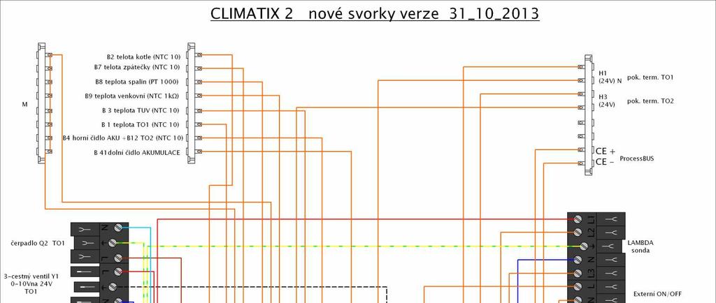
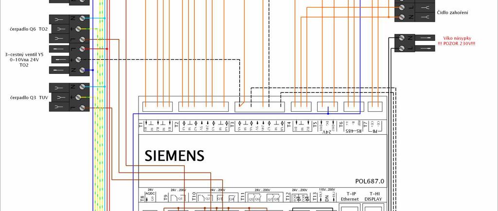
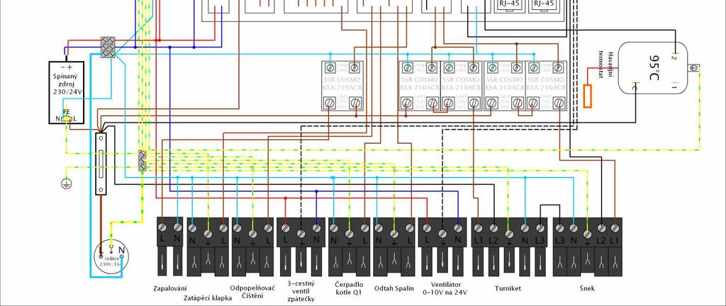
75 - 75 -
76 14.2. ELECTRICAL WIRING DIAGRAM OF CONNECTION OF MIXING VALVES ACTUATORS Y1, Y5, Y7 This applies to electric actuators SIEMENS SSB 61 (for outputs from 0 to 40 kw) or SIEMENS SSC 61 (for outputs from 40 to 100 kw): - supply voltage AC / DC 24V - control signal DC 0 10V - if DC = 0V valve is fully closed (A => AB) - if the supply voltage is disconnected, the actuator spindle maintains its current position - actuator SSC 61 is supplied without a connecting cable Captions: Y control signal DC 0-10V G0 system neutral GND 24V G system potential +24V

77 14.3. ELECTRICAL CONNECTION OF BOILERS IN A CASCADE INCLUDING CONNECTION OF ROOM UNITS POL WITH INTERNET CONNECTION
Electronic Pellet Burner Controller NPBC-V3M
 Electronic Pellet Burner Controller NPBC-V3M SOFTWARE VERSION 3.3a/3.2 page of 27 CHANGES IN THE USER MANUAL OR IN THE CONTROLLER'S SOFTWARE Version of the user manual Changes Page 2.2. The software version
Electronic Pellet Burner Controller NPBC-V3-1
 Electronic Pellet Burner Controller NPBC-V3- SOFTWARE VERSION 3.2/3. page of 3 CHANGES IN THE TECHNICAL AND USER GUIDE OR IN THE SOFTWARE VERSION Technical and User Guide's version Changes Page 2.8. The
ProCon 16, 31, 47 & 75. RVA 63 Boiler and Circuit Controller Commissioning Data.
 ProCon 16, 31, 47 & 75. RVA 63 Boiler and Circuit Controller Commissioning Data. The RVA63 controller can be utilized to control the following system configurations via LPB communication. Equipment Required
INSTALLATION AND OPERATION MANUAL
 INSTALLATION AND OPERATION MANUAL Installation and operation manual Table of contents Page 1. Supplied accessories and intended use... 1 2. General layout and setup of a system... 2 3. Installation...
1 DOCUMENT REVISION CONTROL ELEMENTS... 9
 CONTENTS Contents 1 DOCUMENT REVISION... 8 2 SOFTWARE VERSION... 8 3 BASIC DESCRIPTION... 8 4 CONTROL ELEMENTS... 9 4.1 BASIC DISPLAYS...10 4.2 CONTROL KEYS...11 4.2.1 Rotary button (Press / Turn)...11
OPERATION MANUAL RK-2006LPP AUGER FITTED SOLID FUEL BOILER TEMPERATURE CONTROLLER. Version DC19
 OPERATION MANUAL RK-2006LPP AUGER FITTED SOLID FUEL BOILER TEMPERATURE CONTROLLER Version DC19 1. Application. Controller RK-2006LPP is designed for temperature control of solid fuel fired water boilers
HIGH EFFICIENCY FIRETUBE CONDENSING GAS BOILER
 This manual must be left with owner and should be hung on or adjacent to the boiler for reference. US HIGH EFFICIENCY FIRETUBE CONDENSING GAS BOILER MODELS CHS-85 through CHS-399 APPENDIX A CONTROLLER
TECHNICAL INSTRUCTIONS USE AND MAINTENANCE
 TECHNICAL INSTRUCTIONS USE AND MAINTENANCE Cm Pelet-set For boilers CentroPlus 25/35 and CentroPlus-B 25/35 (solid fuel and wood pellets fuel firing) TUPSCP-K-11-2016-ENG CONTENTS 1.Introduction 2. Status
ARITERM OY. Arimatic 500. User manual
 ARITERM OY Arimatic 500 User manual Table of contents 1. General information... 3 2. Transport, storage and package opening... 3 3. Warranty... 3 4. Installation and commissioning... 4 5. System description...
ProCon 16, 31, 47, 75, 77 & HT. RVA 46. Zone Controller Commissioning Data.
 ProCon 16, 31, 47, 75, 77 & HT. RVA 46. Zone Controller Commissioning Data. The RVA 46 Zone Controller can only be used in conjunction with a RVA47 controlled boiler installation. The RVA46 controller
ProCon Boiler Controller Commissioning Quick Reference Guide
 ProCon Boiler Controller Commissioning Quick Reference Guide This sheet is intended as a quick reference guide and should be read in conjunction with the operating and maintenance manual for the boiler
Boiler controller SPS 4000
 Operating instructions Boiler controller SPS 4000 Version 1.0 Translation of the original German operating instructions for the operator Read and follow the instructions and safety information! Technical
USER MANUAL S203. Controller for three circuits. - control for 2 heating circuits - 1 domestic hot water control. Saving energy, creating comfort
 USER MANUAL S203 Controller for three circuits - control for 2 heating circuits - 1 domestic hot water control Saving energy, creating comfort This user manual consists of two parts. Issues that are intended
Monitoring Software for NPBC-V3M-1 User Manual
 Monitoring Software for NPBC-V3M-1 User Manual User Manual ver 1.5 page 1 of 14 Contents: 1. Introduction... 3 2. Requirements... 3 3. Installing the software... 4 4. Connecting the devices... 4 5. Updating
Mounting and Operating Instructions EB 5610 EN. TROVIS 5600 Automation System TROVIS 5610 Heating and District Heating Controller
 TROVIS 5600 Automation System TROVIS 5610 Heating and District Heating Controller Mounting and Operating Instructions Electronics from SAMSON EB 5610 EN Firmware version 1.40 Edition December 2014 Controller
USE AND MAINTENANCE. Cm Pelet-set (60-90 kw) TECHNICAL INSTRUCTIONS
 TECHNICAL INSTRUCTIONS") CENTROMETAL d.o.o. Glavna 12 40306 Macinec Croatia tel: +385 40 372 600; fax : +385 40 372 611 TECHNICAL INSTRUCTIONS USE AND MAINTENANCE Cm Pelet-set (60-90 kw) For boilers: EKO-CK P 70-110 TUPS-90K-09-2015-E-N-eng
CENTROMETAL d.o.o. Glavna 12 40306 Macinec Croatia tel: +385 40 372 600; fax : +385 40 372 611 TECHNICAL INSTRUCTIONS USE AND MAINTENANCE Cm Pelet-set (60-90 kw) For boilers: EKO-CK P 70-110 TUPS-90K-09-2015-E-N-eng
INSTRUCTIONS FOR USE OF COMBINED BOILER INTENDED FOR COMBUSTION OF BOTH PELLETS AND SOLID FUEL ABC COMBO
 INSTRUCTIONS FOR USE OF COMBINED BOILER INTENDED FOR COMBUSTION OF BOTH PELLETS AND SOLID FUEL ABC COMBO .Technical specifications Boiler power DESCRIPTION Water content in a boiler Required draft Supply
1 DOCUMENT REVISION SOFTWARE VERSION BASIC DESCRIPTION BASIC OVERVIEW OF HYDRAULIC DIAGRAMS HYDRAULIC DIAGRAMS...
 User Manual Contents 1 DOCUMENT REVISION... 4 2 SOFTWARE VERSION... 4 3 BASIC DESCRIPTION... 4 4 BASIC OVERVIEW OF HYDRAULIC DIAGRAMS... 5 4.1 BOILER NOT CONTROLLED BY THE CONTROLLER:... 5 4.2 BOILER CONTROLLED
HMC300. Control unit. Operating Instructions. EMS plus (2014/10) O
 O") HMC300 Control unit EMS plus 6 720 808 471-00.1O Operating Instructions 6 720 813 192 (2014/10) Contents Contents Key to symbols and safety instructions................3 1.1 Key to symbols...........................
HMC300 Control unit EMS plus 6 720 808 471-00.1O Operating Instructions 6 720 813 192 (2014/10) Contents Contents Key to symbols and safety instructions................3 1.1 Key to symbols...........................
OUMAN EH-800 Heating controller USER MANUAL
 OUMAN EH-800 Heating controller USER MANUAL 1 EH-800 is a heating controller for private homes and business facilities having heating systems with circulating water. An extension unit can be obtained as
RVL471 Heating and Domestic Hot Water Controller Basic Documentation
 RVL471 Heating and Domestic Hot Water Controller Basic Documentation Edition: 2.2 Controller series: C CE1P2524E 23.10.2002 Siemens Building Technologies HVAC Products 2/118 HVAC Products 23.10.2002 Contents
ECL Comfort 110, application 116
 Operating Guide ECL Comfort 110, application 116 (valid as of software version 1.08) English version www.danfoss.com How to navigate? Adjust temperatures and values. Switch between menu lines. Select /
Installation Guide. ECL Comfort 210, application A Table of Contents
 1.0 Table of Contents 1.0 Table of Contents... 1 1.1 Important safety and product information..................... 2 2.0 Installation... 4 2.1 Before you start.....................................................
RVL472. Heating Controller. Building Technologies HVAC Products. Series C. including d.h.w. heating
 2 526 Heating Controller including dhw heating Series C RVL472 Multifunctional heating controller for use in residential and non-residential buildings Suited for: Heating zone control with or without room
Heating and D.h.w. Controller RVL482 Basic Documentation
 Heating and D.h.w. Controller RVL482 Basic Documentation Edition: 1.0 Controller series: A CE1P2542en 20.05.2008 Building Technologies Siemens Switzerland Ltd Building Technologies Group International
Boiler controller Lambdatronic S 3200
 Operating Instructions Boiler controller Lambdatronic S 3200 Version 50.04 - Build 05.04 Translation of the original German operating instructions for technicians and operators Read and follow the instructions
EasyTech.One Temperature Controller for Pellet Burner
 EasyTech.One Temperature Controller for Pellet Burner Burner 1 INTRODUCTION... 3 2 ELECTRICAL CONNECTIONS... 3 3 CONTROL PANEL: USE AND FUNCTIONS... 5 3.1 LED... 5 3.2 BUTTONS... 5 3.3 ALARMS... 5 3.1
USE AND MAINTENANCE. Cm Pelet-set TECHNICAL INSTRUCTIONS. (14-35 kw) For boilers: EKO-CK P (EKO-CK 20-40) EKO-CKB P (EKO-CKB 20-40)
 For boilers: EKO-CK P (EKO-CK 20-40) EKO-CKB P (EKO-CKB 20-40)") TECHNICAL INSTRUCTIONS USE AND MAINTENANCE Cm Pelet-set (14-35 kw) For boilers: EKO-CK P 20-40 (EKO-CK 20-40) EKO-CKB P 20-40 (EKO-CKB 20-40) TUPS-K-02-2011-E-N-ENG CONTENTS 1. Introduction....... 2. Status
TECHNICAL INSTRUCTIONS USE AND MAINTENANCE Cm Pelet-set (14-35 kw) For boilers: EKO-CK P 20-40 (EKO-CK 20-40) EKO-CKB P 20-40 (EKO-CKB 20-40) TUPS-K-02-2011-E-N-ENG CONTENTS 1. Introduction....... 2. Status
Boiler controller S-Tronic Plus
 Operating Instructions Boiler controller S-Tronic Plus Version 50.0 - Build 05.0 Translation of the original German operating instructions for technicians and operators Read and follow the instructions
Electronic Pellet Burner Controller NPBC-V3C-K NPBC-V4C-K
 Electronic Pellet Burner Controller FOR DRY PELLET STOVE NPBC-V3C-K NPBC-V4C-K SOFTWARE VERSION 46/2 CHANGES IN MANUAL FOR THE WORK AND THE SOFTWARE OF THE CONTROLLER User Manual version 3.2 Changes 3.3
Condensing Boiler RS100 Controller Training Program
 Condensing Boiler RS100 Controller Training Program Training Program #501102A 062311 www.rinnai.us 2009 Rinnai America Corporation Features and Benefits The RS100 connects directly to the boiler and acts
1. COMMISSIONING OF THE BOILER en DESCRIPTION FUNCTION BUTTON DESCRIPTION SYMBOL DISPLAY
 RC 06 0712_1403 it - Istruzioni TELECONTROLLO en - Remote controller instruction hu - Utasítás TÁVVEZÉRLÉS ru - Руководство по эксплуатации pl - Instrukcja obsługi { 1. Commissioning of the boiler 26 2.
Automation System TROVIS 5400 Ventilation Controller TROVIS Mounting and Operating Instructions EB 5477 EN. Electronics from SAMSON
 Automation System TROVIS 5400 Ventilation Controller TROVIS 5477 ounting and Operating Instructions Electronics from SASON EB 5477 EN Firmware version 2.0x Edition April 2004 Disclaimer of liability Disclaimer
C66. ECL Comfort. User's Guide. Installer's Guide. ECL Comfort C66. User's Guide. Installer's Guide. *vi7cc502* *087R8069* *087R8069* *vi7cc502*
 User's Guide VI.7C.C5.02 2005.09 C66 *vi7cc502* *087R8069* www.danfoss.com ECL Comfort User's Guide ECL Comfort Installer's Guide www.danfoss.com *087R8069* *vi7cc502* Mixing controller with PI controlled
USER MANUAL 9kW LILLY PELLET STOVE
 USER MANUAL 9kW LILLY PELLET STOVE Table of Contents.Overview of Stove Parts... 2.Technical Characteristics... 3 3.Important Information... 4 4.Pellet Specification...5 5.Technology... 6 6.Installation...
Combined boiler. for solid fuel and pellets
 Combined boiler ATTACK WOOD&PELLET for solid fuel and pellets W W W. A T T A C K. S K MODEL STRUC TURE OF THE AT TACK BOILERS THE NEW LINE OF ATTACK BOILERS FOR WOOD AND PELLETS 3000 000 6000 4 ATTACK
M116 / M450 USER AND MAINTENANCE MANUAL FOR MODULATING-CONTROL BOILER WITH GAS BURNER EQUIPPED FOR NATURAL GAS. Type : B23 ATLANTIC 2000
 M SERIES M116 / M45 USER AND MAINTENANCE MANUAL FOR MODULATING-CONTROL BOILER WITH GAS BURNER EQUIPPED FOR NATURAL GAS Type : B23 Country BE CH ES FR GB IE IT LU NL PT Category I2E(R)B I2H I2H I2Esi I2H
C37. ECL Comfort. User's Guide. Installer's Guide. ECL Comfort C37. User's Guide. Installer's Guide *VI7CE602* *087R8070* *087R8070* *VI7CE602*
 User's Guide VI.7C.E6.02 2005.09 C37 *VI7CE602* *087R8070* www.danfoss.com ECL Comfort User's Guide ECL Comfort Installer's Guide www.danfoss.com *087R8070* *VI7CE602* Mixing controller with ON / OFF controlled
ECL Comfort 110, application 130
 Operating Guide ECL Comfort 110, application 130 (valid as of software version 1.08) English version www.danfoss.com How to navigate? Adjust temperatures and values. Switch between menu lines. Select /
SWEBO Bioenergy Manual pellet burner PB50 Rev no. Date Page PBM1: (37) Installation and maintenance instructions
 Installation and maintenance instructions") PBM1:12 2008-10-16 1 (37) Installation and maintenance instructions PBM1:12 2008-10-16 2 (37) TABLE OF CONTENTS 1 GENERAL INFORMATION... 5 1.1 PELLET STORAGE... 6 1.2 CONSTRUCTION AND FUNCTION... 7 1.2.1
PBM1:12 2008-10-16 1 (37) Installation and maintenance instructions PBM1:12 2008-10-16 2 (37) TABLE OF CONTENTS 1 GENERAL INFORMATION... 5 1.1 PELLET STORAGE... 6 1.2 CONSTRUCTION AND FUNCTION... 7 1.2.1
Trinity Tft/Lx Model #s: Tft60-399/Lx Version Date:
 Trinity Tft/Lx Model #s: Tft60-399/Lx150-800 Version Date: 2013-07-26 NEW FEATURES Second Central Heat Input Internal Lead-Lag Control System Sensor Modulation Sensor Alternatives Warm Weather Shutdown
PELLET BURNER PV 350
 PELLET BURNER PV 350 INSTRUCTION MANUAL v1.1 1 PRODUCT DESCRIPTION...3 2 SAFETY RULES...3 3 WARNINGS...4 4 INSTALLATION INSTRUCTIONS...5 4.1 BOILER REQUIREMENTS...5 4.2 PELLET CONTAINER...6 4.3 INSTALLATION
Weather compensated flow temperature control of heating and boiler systems
 Instructions ECL Comfort 110 Application 130 Weather compensated flow temperature control of heating and boiler systems User guide, Installation & Maintenance DH-SMT/DK VI.KT.G3.02 Danfoss 06/2008 How
User Guide UTI-IQCP. Control panel for setting and monitoring of UTI-INV internal temperature regulator. v EN
 User Guide UTI-IQCP Control panel for setting and monitoring of UTI-INV internal temperature regulator v. 1.06 EN 1. MAIN DISPLAY SCREEN The main display screen is divided into five basic monitoring windows
Installation & Operation Manual
 Boiler Control 275 Installation & Operation Manual Multi-Staging D 275 01/12 Replaces:03/09 The Boiler Control 275 is designed to stage up to four condensing or non-condensing, modulating or on-off boilers
HEATING TECHNIQUE. Centrometal d.o.o. - Glavna 12, Macinec, Croatia, tel: , fax: C O2=8% 80 C.
 HEATING TECHNIQUE Centrometal d.o.o. - Glavna 12, 40306 Macinec, Croatia, tel: +385 40 372 600, fax: +385 40 372 611 Technical instructions using of REGULATION hot water boiler PelTec / PelTec-lambda 120
Parameter guide 95M-200 GAS-FIRED DIRECT VENT MODULATING HOT WATER BOILER WARNING WARNING
 95M-200 GAS-FIRED DIRECT VENT MODULATING HOT WATER BOILER! WARNING Revise boiler control parameters only if you fully understand the purpose and result of the changes and on the advice of ECR Technical
ecomax 200 W Boiler regulator FOR SOLID FUEL BOILERS WITH A FAN OPERATION AND MAINTENANCE MANUAL ISSUE:
 Boiler regulator ecomax 200 W FOR SOLID FUEL BOILERS WITH A FAN OPERATION AND MAINTENANCE MANUAL ISSUE: 1.3 APPLICABLE TO SOFTWARE 10.034 10.035 10.036 2010-04-14 TABLE OF CONTENTS 1 Safety... 4 2 General
BIX B-One 100 kw INSTALLATION GUIDE
 BIX B-One 100 kw INSTALLATION GUIDE Dear Customer, We thank you for choosing our product. The Bix B-One 100 Kw is a burner of advanced concept and technology, with a high reliability and construction quality.
SWEBO Bioenergy Manual pellet burner PB20 Rev no. Date Page PBM1: (36) Installation and maintenance instructions
 Installation and maintenance instructions") PBM1:12 2018-01-22 1 (36) Installation and maintenance instructions PBM1:12 2018-01-22 2 (36) TABLE OF CONTENTS 1 GENERAL INFORMATION... 5 1.1 PELLET STORAGE... 5 1.2 CONSTRUCTION AND FUNCTION... 6 1.2.1
PBM1:12 2018-01-22 1 (36) Installation and maintenance instructions PBM1:12 2018-01-22 2 (36) TABLE OF CONTENTS 1 GENERAL INFORMATION... 5 1.1 PELLET STORAGE... 5 1.2 CONSTRUCTION AND FUNCTION... 6 1.2.1
P20. ECL Comfort. User's Guide. Installer's Guide. ECL Comfort P20. User's Guide. Installer's Guide *VI7BD502* *087R8014* *087R8014* *VI7BD502*
 User's Guide VI.7B.D5.02 2005.10 P20 *VI7BD502* *087R8014* www.danfoss.com ECL Comfort User's Guide ECL Comfort Installer's Guide www.danfoss.com *087R8014* *VI7BD502* Boiler controller P20 VI.7B.D5.02
INSTALLATION AND OPERATING INSTRUCTIONS BIOCLASS HM OD (FOR EXTERNAL USE)
") INSTALLATION AND OPERATING INSTRUCTIONS BIOCLASS HM OD (FOR EXTERNAL USE) Thank you for choosing a DOMUSA TEKNIK heating boiler. Within the product range offered by DOMUSA TEKNIK you have chosen BioClass
INSTALLATION AND OPERATING INSTRUCTIONS BIOCLASS HM OD (FOR EXTERNAL USE) Thank you for choosing a DOMUSA TEKNIK heating boiler. Within the product range offered by DOMUSA TEKNIK you have chosen BioClass
Type summary Albatros 2
 OEM Type summary lbatros 2 The lbatros 2 family is a comprehensive range of controls. It offers solutions for basic to complex heating plant. Uniform and integral operating philosophy with clear-text display
ECL Comfort 210 / 296 / 310
 User Guide ECL Comfort 210 / 296 / 310 English version www.danfoss.com Safety Note Necessary assembly, start-up, and maintenance work must be performed by qualified and authorized personnel only. 2 Danfoss
INSTALLATION AND OPERATING INSTRUCTIONS BIOCLASS HM
 INSTALLATION AND OPERATING INSTRUCTIONS BIOCLASS HM Thank you for choosing a DOMUSA TEKNIK heating boiler. Within the product range offered by DOMUSA TEKNIK you have chosen BioClass HM model. With a suitable
USER'S INFORMATION MANUAL
 USER'S INFORMATION MANUAL WARNING: If the information in this manual is not followed exactly, a fire or explosion may result causing property damage, personal injury or loss of life. Do not store or use
bruli.pl V3.5 Operating manual Kutno Software version:
 bruli.pl V3.5 Software version: 1.1.20.0 Operating manual Kutno 2016-10-07 Table of Contents 1. Safety...3 2. Assembly...5 2.1 Environmental conditions...5 2.2 Control panel setup...5 2.3 Connecting the
ecoal.pl V3.5 Adaptive controller Operating manual Kutno Software version:
 ecoal.pl V3.5 Adaptive controller Software version: 1.1.20.0 Operating manual Kutno 2016-10-07 Table of Contents 1. Safety...3 2. Assembly... 5 2.1 Environmental conditions...5 2.2 Control panel setup...5
BIO 30, BIO 50, BIO 95
 BIO 30, BIO 50, BIO 95 STEEL BOILER FOR HEATING WITH BURNER AND AUTOMATIC FUEL FEEDER BIO 30-50 kw POWER USER MANUAL, USER GUIDE, INSTALLATION, USE AND MAINTENANCE OF THE BOILER 1. Introduction Biokaitra
Service Settings. EASY PFA Universal Biomass Heating System Controller. Technical Documentation
 Service Settings EASY PFA Universal Biomass Heating System Controller Technical Documentation Safety Precautions Caution! Schock Hazard! Risk of electrical schock which may cause serious injuries or death.
Controller PCSol 300 FOR SOLAR COLLECTORS. INSTALLATION AND OPERATION MANUAL 62.X.2 REVISION SOFTWARE
 Controller PCSol 300 FOR SOLAR COLLECTORS www.econet24.com PUMP PUMP CIRCULATION PUMP ROTATION CONTROL CIRCULATION PROGRAM HEATER SUPPORT HEATER PROGRAM SIMPLE IN USE INTELLIGENT ALARM CLOCK 10 DAYS CLOCK
Operating instructions
 Operating instructions Control unit - CGL Zone 0.0 C Friday 3/0/08 : 6 Wolf GmbH Postfach 380 D-84048 Mainburg Tel. +49 (0)875/74-0 Fax +49 (0)875/74600 Internet: www.wolf-heiztechnik.de Document no.:
- Data Brochure Universal Reset Module 422
 - Data Brochure Universal Reset Module 422 D 422 08/07 1 Information Brochure Choose controls to match application Application Brochure Design your mechanical applications 2 3 Rough-in Wiring Rough-in
USER MANUAL. OPTIMA 312 ES960C circuit board
 USER MANUAL OPTIMA 312 ES960C circuit board TABLE OF CONTENTS 1. Installation of Optima Design... 3 1.1 Installation of the Control Panel... 3 1.2 Mounting... 3 2. Control Panel... 4 3. Installation...
BM Programming Module. For the heating engineer Installation instructions
 For the heating engineer Installation instructions BM Programming Module WOLF GmbH Postfach 1380 84048 Mainburg Tel. 08751/74-0 www.wolf-heiztechnik.de Document no.: 3062612_201509 Subject to modifications
USER'S INFORMATION MANUAL
 USER'S INFORMATION MANUAL WARNING: If the information in this manual is not followed exactly, a fire or explosion may result causing property damage, personal injury or loss of life. Do not store or use
So old fashioned... As the combustion chamber is completely room sealed, it does not release any smells and does not dirty.
 ARREDO E BENESSERE So old fashioned... An intelligent choice When on a cold winters night the warm glowing flames of the KALDUS boiler are there to welcome you back home, you will be pleased that you decided
INSTALLATION AND OPERATION MANUAL
 INSTALLATION AND OPERATION MANUAL Installation and operation manual Table of contents Page. Supplied accessories and intended use.... General layout and setup of a system... 3. Installation... 3 3.. Mounting
User Manual RBS 24. for model CE series ENERGY. Wall mounted instantaneous combi boiler room sealed chamber
 User Manual for model RBS 24 series ENERGY Wall mounted instantaneous combi boiler room sealed chamber CE 0694 RBS 24 - SERIE ENERGY - RAD - ING - MAN.UT - 1407.1 - DIGITECH TR - MIAH6 - E04 Technical
INSTRUCTION MANUAL & SERVICE MANUAL ORLIGNO 400
 INSTRUCTION MANUAL & SERVICE MANUAL ORLIGNO 400 Content 1. Delivery......................................................................... 3 2. Installation and assembly.........................................................
USE AND MAINTENANCE. Cm Pelet-set TECHNICAL MANUAL. CENTROMETAL d.o.o. Glavna Macinec Croatia tel: ; fax :
 CENTROMETAL d.o.o. Glavna 12 40306 Macinec Croatia tel: +385 40 372 600; fax : +385 40 372 611 TECHNICAL MANUAL USE AND MAINTENANCE Cm Pelet-set TUPS-3-2008-eng-E-N CONTENT 1. Introduction.. 2. Delivery
- Data Brochure Boiler Control 274
 - Data Brochure Boiler Control 274 274_D 03/17 The Boiler Control 274 operates up to four on/off boilers to provide outdoor reset operation, domestic hot water and setpoint operation with priority. When
C62. ECL Comfort. User's Guide. Installer's Guide. ECL Comfort C62. User's Guide. Installer's Guide *VIKME102* *087R8091* *087R8091* *VIKME102*
 User's Guide VI.KM.E1.02 2005.09 C62 *VIKME102* *087R8091* www.danfoss.com ECL Comfort User's Guide ECL Comfort Installer's Guide www.danfoss.com *087R8091* *VIKME102* Double mixing controller C62 VI.KM.E1.02
INSTRUCTION FOR THE USER THC V E OIL BLU
 INSTRUCTION FOR THE THC V E OIL BLU CONTENTS General safety information 4 Precautions 4 Control panel 5 Mode selection 8 User levels 10 Start-up 12 Temporary shutdown 15 Preparing for extended periods
USERS MANUAL FOR GAS BOILERS
 USERS MANUAL FOR GAS BOILERS PLEASE READ THE MANUAL CAREFULLY: IT CONTAINS IMPORTANT INFORMATION REGARDING SAFETY, INSTALLATION, USE AND MAINTENANCE OF THE APPLIANCE MODELS: NOVADENS 24 NOVADENS 24C NOVADENS
WHE 2.24 / WHE 2.24 FF
 EN Wall-hung gas boilers WHE 2.24 WHE 2.24 FF User Guide 300011777-001-C . Contents 1 Introduction.............................................................................3 1.1 Symbols used...........................................................................................3
Manual for the integration in BMS/GTC
 Manual for the integration in BMS/GTC Communication parameters MODBUS RTU and BACNET COMMUNICATION UTBS PRO-REG Software Version 3.6 EN ÍNDEX 1. GENERALITIES...2 1.1. Introduction...2 1.2. signals types...2
PowerRouter application guideline
 PowerRouter application guideline Software installation tool - version 3.4 Before operating the PowerRouter, you may initialize the PowerRouter by using the PowerRouter software installation tool. The
Janfire Pellet Burner Boiler. for single / double burner management (Version 1.1)
") SY325 Janfire Pellet Burner Boiler for single / double burner management (Version 1.1) TECHNICAL DATA SHEET V1.1 rev.12/2007 Contents INTRODUCTION...3 1 THE CONTROL PANEL...4 2 THE KEYS...4 3 THE LEDS...4
SY325 Janfire Pellet Burner Boiler for single / double burner management (Version 1.1) TECHNICAL DATA SHEET V1.1 rev.12/2007 Contents INTRODUCTION...3 1 THE CONTROL PANEL...4 2 THE KEYS...4 3 THE LEDS...4
prestige Control Application Supplement - Type 5 MCBA WARNING
 prestige Control Application Supplement - Type 5 MCBA WARNING This document is intended to be used by a factory trained and qualified heating contractor or service technician only. Read all instructions
USER'S INFORMATION MANUAL
 USER'S INFORMATION MANUAL WARNING: If the information in this manual is not followed exactly, a fire or explosion may result causing property damage, personal injury or loss of life. Do not store or use
ELECTRIC BOILERS FOR CENTRAL HEATING
 ELECTRIC BOILERS FOR CENTRAL HEATING TermoMax INSTRUCTIONS FOR INSTALLATION INSTRUCTIONS FOR INSTALLATION We reserve the right of alternations WE ARE NOT LIABLE FOR DAMAGES RESULTING FROM NON- OBSERVING
For the owner and the heating engineer. Operating and Installation Manual VRC 400. Programmable weather compensator with separat HW time control
 For the owner and the heating engineer Operating and Installation Manual VRC 400 Programmable weather compensator with separat HW time control GB Contents Contents Notes on the documentation..... 4 Symbols
Operation manual. Daikin Altherma ground source heat pump EGSQH10S18AA9W. Operation manual Daikin Altherma ground source heat pump.
 English Table of contents Table of contents About this document About the system. Components in a typical system layout... 3 Operation 3 3. Overview: Operation... 3 3. The user interface at a glance...
RVL471. Heating controller. G2524en. Installation Instructions. 1 Installation. 2 Commissioning
 G2524en Heating controller Installation Instructions RVL471 1 Installation 1.1 Place of installation In a dry room, e.g. the boiler room Mounting choices: In a control panel (on the inner wall or on a
RVL481. Heating Controller. including d.h.w. heating
 2 541 Heating Controller including d.h.w. heating RVL481 Multifunctional and communicating heating controller for use in residential and non-residential buildings. Suited for heating circuit control with
User Manual. Dryer Controller M720
 User Manual Dryer Controller M720 Hardware version 1.00 Software version 1.00 Preliminary version Manual M720 Dryer controller Page 1 of 42 Document history Preliminary version: - Created in April, 2009
Electronic pellet burner controller - NPBC-V3M. Electronic Pellet Burner Controller NPBC-V3M
 Electronic Pellet Burner Controller NPBC-V3M page 1 of 11 INTRODUCTION NPBC-V3M is an advanced, functionally completed controller for pellet burners. All the mechanisms and sensors of the burner, as well
Lago SD3. Differential Controller with Speed Control. Operating and Installation Instructions
 Lago SD3 Differential Controller with Speed Control Operating and Installation Instructions Please observe the safety instructions and read through this manual carefully before commissioning the equipment.
Multi Boiler Guide. Kit #
 Multi Boiler Guide Kit # 550002186 Technical Support @ 800-325-5479 Phone: (315) 797-1310 Fax: (866) 432-7329 e-mail: info@ecrinternational.com web site: www.ecrinternational.com Information and specifications
1/8. Field settings table. Applicable indoor units *HYHBH05AAV3 *HYHBH08AAV3 *HYHBX08AAV3. Notes - 4P C
 1/8 Applicable indoor units *HYHBH5AAV3 *HYHBH8AAV3 *HYHBX8AAV3 Notes - 4P353731-1C - 213.12 2/8 3/8 User settings Preset values Room temperature 7.4.1.1 Comfort (heating) R/W [3-7]~[3-6], step: A.3.2.4
Settings and Maintenance of the CombinAir
 Atmos CombinAir Settings and Maintenance of the CombinAir Issue 13.8.10 Operation and commissioning: The control unit on the front of the CombinAir is used to adjust the settings during commissioning.
User Instructions For TopTronic RS-30
 User Instructions F TopTronic RS-30 430294ENG-Jun02 Hoval Ltd Nthgate Newark Nottinghamshire NG24 1JN Phone 01636 672711 Fax 01636 673532 2 Index 430294ENG-Jun02 Introduction Introduction... 3 Controls...
SD2. Differential Controller. Operating and Installation Instructions F2 72.3
 SD2 Differential Controller Operating and Installation Instructions F2 72.3 i Please follow the safety information and read these Instructions carefully before putting the system into operation. Safety
Pellet burner PELETIX II+ Operating and assembly manual VER_EN_2.0_2015
 Pellet burner EN PELETIX II+ Operating and assembly manual VER_EN_2.0_2015 5. Installation... 8 Table of content 1. Introduction... 3 2. Safety... 3 2.1. Regulations and standards... 3 2.2. Precautions
ENVI Boiler Controller
 GSG Rev. 0.0 6/2/2009 ENVI Boiler Controller Getting Started Guide Installation Date: Harsco Industrial, Patterson-Kelley 100 Burson Street East Stroudsburg, PA 18301 Telephone: (877) 728-5351 Facsimile:
BIOMASS BOILER ATTACK PELLET 30 AUTOMATIC PLUS
 BIOMASS BOILER ATTACK PELLET 30 AUTOMATIC PLUS W W W. A T T A C K. S K MODEL STRUC TURE OF THE AT TACK BOILERS THE NEW LINE OF ATTACK BOILERS FOR WOOD AND PELLETS 3000 000 6000 4 ATTACK FD PELLET yattack
ir-range 8G /03.15 Changes reserved.
 U s e r m a n u a l ic-range is-range ir-range 8G.52.80.00/03.15 Changes reserved. Contents 1. Introduction...3 2. Safety...5 3. Boiler description...6 4. Display and functions...7 4.1 DHW and Heating
Great Britain en. Installation, user and service manual. Control panel HMI Gas 310/610 ECO PRO
 Great Britain en Installation, user and service manual Control panel HMI Gas 310/610 ECO PRO Dear Customer, Thank you very much for buying this appliance. Please read through the manual carefully before
VERSO-P, VERSO-R Series Air Handling Units with C3 Control System Electrical Installation and Operation Manual
 VERSO-P, VERSO-R Series Air Handling Units with C3 Control System Electrical Installation and Operation Manual EN Table of Contents 1. INSTALLATION MANUAL...3 1.1. Air Handling Units Sections Connection...3