Ironman X- Class 410 Recumbent Bike with Bluetooth
|
|
|
- Dina Wilkerson
- 5 years ago
- Views:
Transcription


1 OWNER S MANUAL Ironman X- Class 410 Recumbent Bike with Bluetooth Model 6152 The specifications of this product may vary from this photo and are subject to change without notice. IRONMAN, IRONMAN TRIATHLON and M-DOT are registered trademarks of World Triathlon Corporation. This product is licensed by the World Triathlon Corporation.
2
3 TABLE OF CONTENT SERVICE LABEL PLACEMENT PRODUCT SAFETY OVERVIEW DRAWING HARDWARE AND TOOLS LIST PART LIST ASSEMBLY SEAT AND BACKREST ADJUSTMENTS COMPUTER TROUBLESHOOTING & MAINTENANCE WARM UP WARRANTY FAX FORM
4 SERVICE IMPORTANT: FOR NORTH AMERICA ONLY To request product service and order replacement parts, please call our customer service department at: Monday through Friday, 8:00 AM-5:00 PM Pacific Standard Time, or us at: Please visit our website at Please have the following information ready when requesting for service: Your name Phone number Model number Serial number Part number Proof of Purchase Before returning this product to the store please contact customer service at the contact number. Paradigm Health & Wellness, Inc Jellick Ave City of Industry, CA USA 2
5 LABEL PLACEMENT CAUTION (Model 6152) ATTENTION (N 6152) Pedal (0-1) Into the (0-2) Into the (0-1) (0-2) Maximum weight capacity is 350 lbs. AVERTISSEMENT Le poids maximum pout ce produit est 159 kgs. For customer assistance call: am - 5 pm PST Mon - Sun Pour le service a la clientèle composer le: Du lundi au dimanche 8:00 h - 17 h (HNP) MADE IN CHINA / FABRIQUÉ EN CHINE Under Penalty of law this tag not to be removed except by the consumer ALL NEW MATERIAL CONSISTING OF POLYURETHANE FOAM PAD_100% REGISTRY NO. VA25302 (CN) Certification is made by the manufacturer that the materials in this article are described in accordance with law. Paradigm Health and Wellness, Inc Jellick Ave. City of Industry, CA USA SOUS PEINE DE SANCTION LÉGALE, CETTE ÉTIQUETTE NE PEUT ÊTRE ENLEVÉE PAR UNE PERSONNE AUTRE QUE LE CONSOMMATEUR ENTIÈREMENT FABRIQUÉ DE MATÉRIAUX NEUFS REMBOURRAGE DE MOUSSE DE POLYURÉTHANE 100% NO D ENREGISTREMENT VA25302 (CN) Cette étiquette est apposée Conformément aux lois Canadiennes. Paradigm Health and Wellness, Inc Jellick Ave. City of Industry, CA USA NOTICE This article does not meet the flammability requirements of California Bureau of Home Furnishings technical bulletin. 117 Care should be exercised near open flame or with burning cigaretts. AVIS Ce produit ne satisfait pas aux critères d inflammabilité spécifiés à l article 117 du devis technique ducalifornia Bureau of Home Furnishings. Ne pas utiliser près d une source de chaleur ou d une flamme nue (cigarettes, etc.) 3
6 PRODUCT SAFETY Basic precautions should always be followed, including the following safety instructions when using this equipment. Read all instructions before using this equipment. 1. Read all the instructions in this manual and do warm up exercises before using this equipment. 2. Before exercising and to avoid injuring your muscles, perform warm-up exercise for each muscle group is highly recommended. Please refer to Warm Up section of the Owner s Manual. 3. Please make sure all components are not damaged and in working order before use. This equipment should be placed on a flat surface while in use. Using a mat or other material on the ground is recommended. 4. Please wear proper clothes and shoes when using this equipment; do not wear clothes that might catch in any part of the equipment. 5. Do not attempt any maintenance or adjustments other than those described in this manual. Should any problems arise, discontinue use and consult with customer service at Paradigm. 6. Caution should be taken when getting on or off the equipment. To get on, make sure the left foot pedal is at the lowest position. Grab the stationary handlebar firmly with both hands then place your left foot onto the left foot pedal. Once your left foot is secured, place your right foot onto the right foot pedal. To begin exercising, push/pull on the handrails first and then follow with leg motion. To get off, come to a complete stop and do the above in reverse. 7. Keep dry - do not operate in wet or moist condition. 8. Do not use the equipment outdoors. 9. This equipment is for household use only. 10. Only one person should be on the equipment at any time. 11. Keep children and pets away from the product while in use. 12. This machine is designed for adults only. 13. This product requires a minimum of 6 feet of space for safe operation. 14. If you feel any chest pains, nausea, dizziness, or short of breath, you should stop exercising immediately and consult your physician before continuing. 15. The maximum weight capacity for this product is 350 lbs /159 kgs. WARNING: Before beginning any exercise program consult your physician. This is especially important for the people who are over 35 years old or who have pre-existing health problems. Read all instructions before using any fitness equipment. CAUTION: Read all instructions carefully before operating this product. Retain this Owner s Manual for future reference. 4
7 OVERVIEW DRAWING s H-4 N-9 N-10 H-5 H-6 H-7 G-2 H-3 H-10 H-9 H-11 H-12 G-3 G-13 G-9 N-7 U-1 H-2 H-1 H-8 I-6 I-5 N-6 N-8 C-5 C-1 C-3 G-1 C-4 N-11 N-5 N-5 G-10 G-11 G-7 G-8 G-5 G-6 G-14 U-2 G-4 G-12 F-2 F-1 E-9 C-2 R D-1 M-8 M-13 M-1 M-7 M-11 A-3 M-4 M-5 M-12 M-3 M-6 M-10 M-2 M-9 D-3 D-4 D-5 D-6 D-2 J-8 J-7 J-11 J-9 C-1 A-1 B-4 B-5 B-8 Q O-2 B-10 J-1 J-3 J-4 A-2 B-2 B-7 B-9 B-3 B-6 B-1 P K-7 N-4 N-3 N-6 I-2 I-1 N-2 I-4 I-3 L-3 L-2 L-7 L-1 L-8 L-4 L-6 L-5 L-10 L-11 L-9 J-10 J-2 J-4 J-3 O-1 J-5 J-12 K-12 K-6 K-3 K-4 K-5 K-1 E-2 E-1 E-9 N-3 N-4 E-4 E-8 E-3 E-5 E-7 E-6 N-1 K-11 K-10 K-9 K-8 K-2 T D-7 D-8 D-9 D-10 D-11 D-12 D-13 D-14 D-15 D-16 D-17 J-6 5
8 HARDWARE & TOOLS LIST N-2 M8*15L 4PCS 2 3 N-3 D13.2 4PCS N-4 D16 4PCS N-5 M6*15L 1PC N-3 D13.2 4PCS N-1 M8*60L 4PCS 7A N-4 D16 4PCS N-6 M8*50L 4PCS N-7 M6*10L 2PCS N-8 D22 2PCS N-6 M8*50L 2PCS Step 7B N-15 Allen Wrench 5mm 1pc N-14 Allen Wrench 4mm 1pc N-13 Open Wrench 13,15mn 1pc N-12 Allen Wrench with Phillips Screwdriver 6mm 1pc Step 7C N-5 M6*15L 4PCS 6
9 PART LIST No. Description Q ty No. Description Q ty A Computer set 1 D-11 Electric cable 1 A-1 Computer 1 D-12 Bolt M5x0.8x12L 1 A-2 Computer Screw M5*0.8*10L 4 D-13 Sensor cable 1 A-3 Audio cable 1 D-14 Lower computer cable 1 B Handlebar post set 1 D-15 Tension cable 1 B-1 Handlebar post 1 D-16 Lower hand pulse cable 2 B-2 Fixing plate of computer 1 D-17 Upper hand pulse cable 1 B-3 Computer bracket 1 E Front stabilizer set 1 B-4 Upper hand pulse cable 1 E-1 Front stabilizer 1 B-5 Upper computer cable 1 E-2 End cap 2 B-6 Allen bolt M8*1.25*45L 1 E-3 Round moveable wheel 2 B-7 Nylon nut M8*1.25*8T 1 E-4 Allen bolt M8x1.25x40L 2 B-8 Bushing D8xD12.7x23 1 E-5 Domed nut M8x1.25x15L 2 B-9 Cross screw ST4.2x1.4x15L 2 E-6 Bushing D22.2xD8.2x7T 4 B-10 Bolt M5*0.8x15L 2 E-7 Spring washer D15.4xD8.2x2T 2 C Handlebar set 1 E-8 Flat washer D16xD8.5x1.2T 6 C-1 Handlebar 1 E-9 Adjustable Levers 4 C-2 Hand pulse cable 2 F Rear stabilizer set 1 C-3 Cross screw ST4x1.41x25L 2 F-1 Rear stabilizer 1 C-4 Hand pulse cable 2 F-2 End cap 2 C-5 Cable plug 1 G Seat post set 1 D Main frame set 1 G-1 Seat adjustment bracket 1 D-1 Main frame 1 G-2 Bushing 2 D-2 Bearing M8x1.25x15L 2 G-3 C-clip 2 D-3 Sliding beam 1 G-4 Bushing D29xD11.9x9T 2 D-4 Buffer 4 G-5 Eccentric shaft 1 D-5 Allen bolt M8x1.25x15L 4 G-6 Link stopper 1 D-6 Nylon nut M8*1.25*8T 4 G-7 Nut 1 D-7 Fixing clip 1 G-8 Hex bolt M8x1.25x15L 1 D-8 Cross screw ST4.2x1.4x15L 2 G-9 Spring D1.8xD14x70L 1 D-9 Motor 1 G-10 Bolt M5x0.8x10L 2 D-10 Cable plug 2 G-11 Protective cover 1 7
10 PART LIST No. Description Q ty No. Description Q ty G-12 Bushing 1 J-8 C-clip D22.5xD18.5x1.2T 2 G-13 Adjustable pole 1 J-9 Waved washer D27xD21x0.3T 1 G-14 Cross screw ST4x1.41x12L 1 J-10 Nylon nut M6x1.0x6T 4 H Bracket adjustable tube set 1 J-11 Hex bolt M6x1.0x15L 4 H-1 Backrest bracket 1 J-12 Multiple-groove belt 1 H-2 Pin 1 K Fly-wheel set 1 H-3 Swing shaft 1 K-1 Fly-wheel 1 H-4 End cap 1 K-2 Little fly-wheel 1 H-5 Spring D1.0x K-3 Bearing 1 H-6 Nut M18x1.5x14 1 K-4 Bearing D35x16 1 H-7 Backrest Adjustment Knob 1 K-5 Bearing 2 H-8 Hex bolt M8x1.25x15L 2 K-6 C-clip D15.5xD10.8x1T 2 H-9 Flat washer D25xD8.5x2T 2 K-7 Nylon nut 3/8"-26UNFx6.5T 2 H-10 Bushing D29xD12.1x9T 2 K-8 Bearing 1 H-11 Spring washer D15.4 xd8.2x2t 2 K-9 Fixing ring 1 H-12 screw cover D28x14(M8) 2 K-10 Flywheel axle 1 I chain cover set 1 K-11 Nut D9.5x8T(3/8"-26UNFx8T) 1 I-1 Left chain cover 1 K-12 Washer D36.8xD31.5x1T 1 I-2 Right chain cover 1 L Fixing plate for magnet set 1 I-3 Pin 3 L-1 Fixing plate for magnet 1 I-4 Cross screw ST4.2x1.4x20L 19 L-2 Hex bolt M6x60L 1 I-5 Left chain cover 1 L-3 Nut M6x1x6T 1 I-6 Right chain cover 1 L-4 Nylon washer D6xD19x1.5T 1 J Crank set 1 L-5 Flat washer D13xD6.5x1.0T 1 J-1 Left crank 1 L-6 Nylon nut M6x1x6T 1 J-2 Right crank 1 L-7 Spring D1.0x55L 1 J-3 screw cover D26x11L 2 L-8 Hex bolt M8x52L 1 J-4 Anti-loosen nut M10x1.25x10T 2 L-9 Nylon nut M8x1.25x8T 1 J-5 Belt wheel 1 L-10 Magnet cell 8 J-6 Round magnet 1 L-11 Magnet 9 J-7 Crank axle set 1 M Idle wheel set 1 8
11 PART LIST No. Description Q ty No. Description Q ty M-1 Fixing plate for idle wheel 1 N-8 Curved washer D22xD8.5x1.5T 2 M-2 Bearing 2 N-9 Screw 1/4"x20x40L, 4 M-3 Spring D2.2xD14x55L 1 N-10 screw cover 4 M-4 Nylon nut M8x1.25x8T 1 N-11 Flat washer D14xD6.5x0.8T 4 Allen Wrench with Philips M-5 Plastic washer D50xD10x1.0T 1 N-12 Screwdriver 6mm 1 M-6 Flat washer D30xD8.2x6T 1 N-13 Open Wrench 13,15mm 1 Plastic flat washer M-7 D10xD24x0.4T 1 N-14 Allen Wrench 4mm 1 M-8 Allen bolt M8x1.25x30L 1 N-15 Allen Wrench 5mm 1 M-9 C-clip 1 O Pedal set 1 M-10 Waved washer D21xD16.2x0.3T 1 O-1 Right Pedal 1 M-11 Flat washer D24xD16x1.5T 1 O-2 Left Pedal 1 M-12 Sleeve D3x30L 2 P Upper protective cover 1 M-13 Spacer D17.8xD8.2x5.2 1 Q Bottle holder 1 N Screw set 1 R Seat 1 N-1 Carriage bolt M8x1.25x60L 4 S Air backrest 1 N-2 Cap nut M8x1.25x15L 4 T Adaptor 1 N-3 Spring washer D13.2xD8.2x2T 8 T1 A/C Plug 1 N-4 Flat washer D16xD8.5x1.2T 8 U Adjustable pole set 1 N-5 Allen Screw M6x1x15L 5 U-1 Adjustable pole(ii) 1 N-6 Allen bolt M8x1.25x50L 6 U-2 Foam 1 N-7 Screw M6x1x10L 2 9
12 ASSEMBLY Tool: N-13 Open Wrench 13,15mm 1PC E-9 D-1 E-9 1.Front and Rear Stabilizer Installation 1.1 Front Stabilizer Installation. Lift up the main frame (D-1) from the front, and then align the Front Stabilizer (E-1) onto the front curve of the Main Frame (D-1). Insert 2 Square Neck Screws (N-1) from the bottom, followed by 2 Flat Washers (N-4), 2 Spring Washers (N-3) and 2 Cap Nuts (N-2). Hold the Front Stabilizer (E-1) to the Main Frame (D-1) then tighten by using the open wrench 13, 15mm (N-13) provided. 1.2 Rear Stabilizer Installation. Repeat the above step to install the REAR stabilizer (F-1). 1.3 Adjustable Levelers Turn the Adjustable Levelers (E-9) to the desired height and make sure the bike is stable on the floor after the adjustment. Proper leveling will reduce wobbling and squeaking. Hardware: N-1 Carriage Bolt N-2 Cap Nut N-3 Spring washer N-4 Flat washer M8x1.25x60L M8x1.25x15L D13.2xD8.2x2T D16xD8.5x1.2T 4PCS 4PCS 4PCS 4PCS 10
13 ASSEMBLY A B 2.Backrest Adjustable tube fixed Pull out the Backrest Adjustment Knob (H-7), see diagram A, then adjust the Backrest bracket (H-1) into any of the 3 adjustment holes. Then, install the Allen Screw (N-5) into the Backrest bracket (H-1) by using the 5mm Allen Wrench (N-15) provided as shown in diagram B. Tool: Hardware: N-15 Allen Wrench 5mm 1PC N-5 Allen Screw M6*1*15L 1PC 11
14 ASSEMBLY B A B-1 c B-1 Tool: D-1 N-12 Allen Wrench with Phillips Screwdriver 6mm 1PC 3. Handlebar Post Installation Slide the Upper protective cover (P) onto the Handlebar Post (B-1) see Pic. A. Pull out the Upper pulse cable (B-4) from the Handlebar Post (B-1) as shown in Pic. B. Then connect it with the Lower hand pulse cable (D-16) from the Main Frame (D-1). Connect the Computer cable (B-5) from the Handlebar Post (B-1) to the Lower computer cable (D-14) from the Main Frame (D-1) as shown in Pic. C. CAUTION: To prevent damage, ensure that the wires are not excessively folded or pinched during installation. Wires must stay connected for the computer to function properly. CAREFULLY insert the Handlebar Post (B-1) into the Main Frame (D-1) and attach it using four Allen Bolts (N-6), four Spring Washers (N-3) and four Washers (N-4). Tighten the Handlebar Post (B-1) to the Main Frame (D-1) using the 6mm Allen Wrench (N-12) provided. Hardware: N-3 Spring washer D13.2xD8.2x2T 4PCS N-4 Flat washer D16xD8.5x1.2T 4PCS N-6 Allen Bolt M8x1.25x50L 4PCS 12
15 ASSEMBLY Tool: D-1 N-14 Allen Wrench 4mm 1PC 4. Computer Installation Remove the four Screws (A-2) from the back of the Computer (A-1) Connect the upper pulse cable (B-4) to the console (B-4) pulse cable. Connect the computer cable (B-5) to the 9 pin WHITE socket in the back of the computer. Install the Computer onto the computer plate (B-2) on the front post and tighten the four Screws (A-2) with the Allen Wrench (N-14). 13
16 ASSEMBLY J-1 J-2 D-1 Tool: N-13 Open Wrench 13,15mm 1PC 5. Foot Pedals Installation Put the pedal strap onto the Left and Right pedal first. The Cranks and Foot Pedals are marked R for Right and L for Left. Insert the pedal shaft of the Left Foot Pedal (O-2) into the threaded hole of the Left Crank (J-1). Turn the pedal shaft by hand in the COUNTER-CLOCKWISE direction until snug. Note: DO NOT turn the Left pedal shaft in the clockwise direction, doing so will strip the threads. Tighten the pedal shaft of the Left Foot Pedal (O-2) with the Open Wrench (N-13) provided. Insert pedal shaft of the Right Foot Pedal (O-1) into the threaded hole of the Right Crank (J-2). Turn the pedal shaft by hand in the CLOCKWISE direction until snug. Tighten the pedal shaft of the Right Foot Pedal with the Open Wrench (N-13) provided. 14
17 ASSEMBLY Tool: B-1 N-12 Allen Wrench with Phillips Screwdriver 6mm 1PC 6. Bottle Holder Installation Remove the two pre-installed Screws (B-10) from the Handlebar Post (B-1) using the 6mm Allen Wrench with Phillips screwdriver (N-12). Attach the Bottle Holder (Q) onto the handlebar and tighten with the same screws. 15
18 ASSEMBLY Tool: N-12 Allen Wrench with Phillips Screwdriver 6mm 1PC N-15 Allen Wrench 5mm 1PC N-8 N-6 C A-1 C-5 C-2 D-17 C-5 D-17 A-2-1 C-2 D-17 D-17 C-2 A-2 N-7 N-7 U-1 A-3 C-5 7A. Seat Handlebar installation Attach the Seat Handlebar (C) with two Allen bolts (N-6) and two Curved Washers (N-8) tighten using the 6mm Allen Wrench (N-12). Slide the Hand Pulse cable (C-2) UNDER the Seat Adjustment bracket (G-1), then connect Hand Pulse Cable (C-2) and Upper hand pulse cable (D-17) see Pic (A-1). Gently rotate the attached cable so it fits through the slot (see Pic. A-2-1) then insert the Cable Plug (C-5) into the hole, (see Pic. A-3.) Assemble Adjustable handle (U-1) with two Screws (N-7) using the 5mm Allen Wrench (N-15). Hardware: N-6 Allen Bolt M8x1.25x50L 2PCS N-8 Curved Washer D22xD8.5x1.5T 2PCS N-7 Screw M6x1x10L 2PCS 16
19 ASSEMBLY Tool: N-15 Allen Wrench 5mm 1PC Hardware: N-11 Flat Washer 4PCS N-5 Allen Screw M6*1*15L 7B. Seat Installation 4PCS Attach the Seat (R) to the Seat adjustment bracket (G-1). Tighten with four Allen Screws (N-5) and four Flat Washers (N-11) using the 5mm Allen Wrench provided (N-15). Tool: N-14 Allen Wrench 4mm 1PC Hardware: N-9 Hex Flange Bolt 1/4-20x40L 4PCS N-10 Screw Cover D28x17xM6 4PCS 7C. Backrest installation Align and hold the Backrest (S) onto the Backrest bracket (H-1),use 4mm Allen Wrench (N-14) to tighten four Bolts (N-9) then place 4 screw covers (N-10), over the bolt heads. 17
20 ASSEMBLY I-1 T-1 8. Adaptor Installation Plug one end of the Adaptor (T) into the power jack (T-1) of the power supply cable on the front of the Left Chain Cover (I-1).Before plugging in, make sure to carefully check the specifications on the Adaptor. Plug the other end of the Adaptor (T) to the electrical wall outlet. 18
21 SEAT AND BACKREST ADJUSTMENTS Seat Adjustment Push lever forward to unlock, slide the seat to desired position, and release the lever to lock. To fully tighten and reduce wobbling, pull back on the lever until it s snug. Backrest Adjustment Pull knob out to unlock, release knob into 1 of the 3 holes on the Backrest bracket (H-1). 19
22 MOVING THE BIKE Move the bike by using the handlebar located on the Rear Stabilizer (F-1). 20

23 COMPUTER BUTTON FUNCTION: ON/OFF FAN QUICK START Turn the fan on or off To start or stop workout STOP UP/DOWN RESET To select training mode or adjust function value In stop mode, press the button to return to main menu. Press and hold for 2 seconds to reboot the computer and reset all values to 0. ENTER RECOVERY Confirm setting or selection To test heart rate recovery level. 21


24 COMPUTER DISPLAY FUNCTION Function Display Range Setting Range Unit TIME 00:00~99:59 ±1;00:00~99:00 Minutes DISTANCE 0.0~99.99 ±1;00:00~99:00 ML CALORIES 0~9999 ±10;00:00~9990 CAL PULSE 30~230 ±1; 30~230 BPM SPEED 0.0~99.9 N/A ML RPM 0~999 N/A RPM WATT 0~999 ±5; 10~350 W OPERATING PROCEDURE 1.POWER ON/OFF After connecting the power, the console will power on with a long beep sound, LCD display all segments and then enter into User Profile set up mode. Console will enter sleep mode after 5 minutes of inactivity. Quick Start Press QUICK START to start exercise in MANUAL mode immediately without inputting any settings. 22
25 COMPUTER 2. USER PROFILE Press UP / DOWN to select User #. Press UP / DOWN to turn profile editing on or off. If you choose EDIT ON, you can edit the profile values below. Use UP / DOWN and ENTER to input profile value of sex, age, height and weight. The console needs your profiles to better calculate the work out values. 3. WORKOUT SELECTION In main menu, press UP/DOWN to scroll through MANUAL, PROGRAM (12 programs), USER PROGRAM, HRC and WATT. Press ENTER to confirm selection. 3.1 Manual mode Before exercising in Manual mode, user can set up Time, Distance, Calories, and Pulse target and press ENTER to confirm. After set up of all the targets, press the START to start workout. Resistance level can be adjusted during exercise by pressing UP or DOWN Press STOP to pause the workout reading, and you can press START to continue the workout. Press RESET to return to main page. 23


26 COMPUTER 3.2. Program Mode Press UP or DOWN to select between 12 different workout programs and then press ENTER to set up Target Time. Press START to start workout. Resistance levels can be adjusted during exercise by pressing UP or DOWN Press STOP to pause the workout reading, and you can press START to continue the workout. Press RESET to return to main page. 24

 Input or select your user profile U1-U4. HRC will automatically adjust the machine s resistance levels to keep you at your selected target heart rate.")
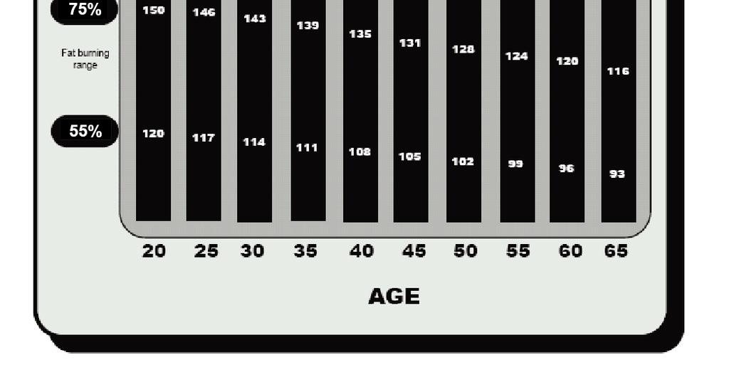
27 COMPUTER 3.3 User Program User Program allows you to create your own workouts based on resistance level and time intervals. Press UP and DOWN to create the profile, press ENTER to input additional resistance level, then press and hold ENTER for 2 seconds to exit profile stetting. Press START to start work out. Standard work out time is 20 minutes. Press STOP to pause the workout reading, and you can press START to continue the workout. Press RESET to return to main page. 3.4 Heart Rate Control (HRC) Input or select your user profile U1-U4. HRC will automatically adjust the machine s resistance levels to keep you at your selected target heart rate. There are 4 target heart rate zone :55%, 75%, 90% and TAG (allows you to set your own target heart rate ); press UP and DOWN to select one program and press ENTER to set up exercise time. Press START to start workout. If the console does not receive the pulse signal, the bottom LCD will show Pulse Input for reminder. Press STOP to pause the workout reading, and you can press START to continue the workout. Press RESET to return to main page. 25

28 COMPUTER 26


29 COMPUTER 3.5 WATT Press UP and DOWN to setting WATT and Time target. Press START to start work out. Press STOP to pause the workout reading, and you can press START to continue the workout. Press RESET to return to main page. 4. Recovery : A fitness test which measures how quickly your heart rate returns to normal after exercising After exercising press RECOVERY and place both hands on the hand pulse. TIME starts counting down from 00:60 to 00:00. Screen will display your heart rate recovery status with the F1, F2.to F6. F1 represents the fastest recovery time, F6 represents the slowest. Press the RECOVERY button again to return to main display. Start Recovery Function Test Result 27

30 COMPUTER 5. Bluetooth Mode Enable Bluetooth on your smart device. Search for and connect to console (name is on the back of the console). When your smart device is connected to the console, the Bluetooth symbol will appear on the LCD. Please note: 1. Holding down the RESET button for 2 seconds will reset the console and your Bluetooth connection. 28
31 TROUBLESHOOTING & MAINTENANCE TROUBLESHOOTING Computer not working correctly Check to make sure the computer cable is connected securely. Check that the AC Adaptor is securely connected to the Power Supply Cable and to the electrical wall outlet. The bike trainer wobbles or shakes when in use Turn the adjustable leveler on the front stabilizer or U shape rail as needed to level the bike trainer. Squeaking noise when in use The bolts may be loose on the bike trainer. Inspect all bolts and tighten as needed. No readings or inconsistent/erratic heart rate readings Always hold on to the handlebar grip sensors with both hands instead of just one. Try to maintain moderate pressure while holding onto the hand pulse sensors. Make sure that the wire connections for the hand pulse sensors are secured. Make sure to wipe sweat off your hands. MAINTENANCE Cleaning The bike trainer can be cleaned with a soft cloth and mild detergent. Do not use abrasives or solvents on plastic parts. Please wipe your perspiration off the bike trainer after each use. Be careful not to get excessive moisture on the computer display panel as this might cause an electrical hazard or electronics to fail. Please keep the bike trainer, especially the computer console, out of direct sunlight to prevent screen damage or premature wear. Please inspect all assembly bolts and pedals on the machine for proper tightness every week. Storage Store the bike trainer in a clean and dry environment away from children. Thread sealant instruction If any parts need to be applied thread sealant, the parts must be cleaned before applying. It needs at least 8 hours to a day to wait for the sealant to dry, do not use the bike until the thread sealant is completely dry. 29
32 WARRANTY MANUFACTURER S LIMITED WARRANTY Paradigm Health & Wellness warrants to the original purchaser that this product is free from defects in material and workmanship when used for the purpose intended, under the conditions that it has been installed and operated in accordance with Paradigm s Owner s Manual. Paradigm s obligation under this warranty applies to the following: COMPONENT Frame Normal Wearable Parts /Electronics Labor and Other Parts LENGTH OF WARRANTY Lifetime 2 years (upholstery, brake, pads, foam grips, pedals etc ) 5 years Exclusions from Warranty Coverage: Paradigm does not warrant against and is not responsible for, and no implied warranty shall be deemed to cover, any product failure, product malfunction, or damages attributable to: 1. Improper installation and/or failure to abide by Paradigm s installation guidelines; 2. Use of this product beyond normal home use, or in an application for which it was not designed; 3. Cosmetic items such as scratches, dents or discolorations; 4. Damage caused by normal wear and tear, vandalism, accidental or by animals; 5. Any act of Nature (such as fire, flooding, snow, ice, hurricane, earthquake, lightning or other natural disaster), environmental condition (such as air pollution, mold, mildew, etc.), or staining from foreign substances (such as dirt, grease, oil, etc.); 6. Normal weathering due to exposure to sunlight, weather and atmosphere which can cause colored surfaces to, among other things, flake, chalk, accumulate dirt or stains. 7. Improper operation, alteration, handling, storage, abuse or neglect of the products. Paradigm, using its sole discretion, will either repair or replace free of charge any part(s) proven to be defective under normal home use. Any repair or replacement shall provide no new warranty coverage, but shall retain only the remaining portion of the original product s warranty. This warranty is offered only to the ORIGINAL purchaser and is not transferable. Proof of original purchase is required. Ordering Replacement Parts For best service, please our customer service department: Service@paradigmhw.com Response Time: 1-2 Business Days Or call toll free at Daily 8:00 AM - 5:00 PM (PST). Response Time may vary. When ordering replacement parts please have the following information ready: 1. Owner s Manual 2. Model Number 3. Description of Parts 4. Part Number 5. Date of Purchase 28
33 WARM UP Quadriceps Stretch With one hand against a wall for balance, reach behind you and pull your right foot up. Bring your heel as close to your buttocks as possible. Hold for 15 counts and repeat with left foot up. Inner Thigh Stretch Sit with the soles of your feet together with your knees pointing outward. Pull your feet as close to your groin as possible. Gently push your knees towards the floor and hold for 15 counts. Toe Touching Slowly bend forward from your waist, letting your back and shoulders relax as you stretch toward your toes. Reach down as far as you can and hold for 15 counts. Hamstring Stretch Sit with your right leg extended. Rest the sole of your left foot against your right inner thigh. Stretch toward your toe as far as possible. Relax and hold for 15 counts. Repeat with left leg extended. 30
34 FAX FORM Paradigm Health & Wellness, Inc. PARTS REQUEST FAX FORM Please fax this form to ( ) OR YOU CAN CUSTOMER SERVICE REQUESTS TO NAME: ADDRESS: CITY STATE ZIP TELEPHONE: (Day) (Night) ( Address) SERIAL#: MODEL#: PURCHASE DATE: PURCHASE FROM: PART # DESCRIPTION/REASON QTY YOUR ORDER WILL BE PROCESSED WITHIN 3 BUSINESS DAYS OFFICIAL USE ONLY SHIP DATE: TRK #: BACK ORDER: 32
IRONMAN Recumbent Bike with Bluetooth
 OWNER S MANUAL IRONMAN Recumbent Bike with Bluetooth Model 6155 The specifications of this product may vary from this photo and are subject to change without notice. IRONMAN, IRONMAN TRIATHLON and M-DOT
Multi-Angle Utility Bench
 Multi-Angle Utility Bench MPORTANT: Read all instructions carefully before using this product. Retain this owner s manual for future reference. The specifications of this product may vary from this photo
Leg Develop Attachment
 OWNER S MANUAL Leg Develop Attachment 6839.1 122215 The specifications of this product may vary from this photo and are subject to change without notice. IRONMAN, IRONMAN TRIATHLON and M-DOT are registered
Power Tower
 Power Tower MPORTANT: Read all instructions carefully before using this product. Retain this owner s manual for future reference. The specifications of this product may vary from this photo and, subject
Safety Instructions. Do not work out immediately after meals!
 Safety Instructions To ensure the best safety of the exerciser, regularly check it for damage and worn parts. If you pass on this exerciser to another person or if you allow another person to use it, make
Standard Olympic Weight Bench
 OWNER S MANUAL Standard Olympic Weight Bench 6836.3 051016 The specifications of this product may vary from this photo and are subject to change without notice. IRONMAN, IRONMAN TRIATHLON and M-DOT are
USER S MANUAL Taurus Racing Bike Z9 Pro TF-Z9-PRO
 USER S MANUAL Taurus Racing Bike Z9 Pro TF-Z9-PRO 1 Safety Instructions To ensure the best safety of the exerciser, regularly check it on damages and worn parts. If you pass on this exerciser to another
Front Drive Elliptical Model No: E750
 BODY WORX Front Drive Elliptical Model No: E750 Retain this owner s manual for future reference Read and follow all instructions in this owner s manual Version A 1 Safety Instructions To ensure the best
MAGNETIC ELLIPTICAL TRAINER
 MAGNETIC ELLIPTICAL TRAINER SF-E3609 USER MANUAL IMPORTANT: Please read this manual carefully before using the product. Retain owner s manual for future reference. For Customer Service, please contact:
PINK MAGNETIC RECUMBENT BIKE
 PINK MAGNETIC RECUMBENT BIKE P8400 USER MANUAL IMPORTANT! Please retain owner s manual for maintenance and adjustment instructions. Your satisfaction is very important to us, PLEASE DO NOT RETURN UNTIL
MAGNETIC ELLIPTICAL TRAINER SF-E3416 USER MANUAL
 MAGNETIC ELLIPTICAL TRAINER SF-E3416 USER MANUAL IMPORTANT: Please read this manual carefully before using the product. Retain owner s manual for future reference. For Customer Service, please contact:
MAGNETIC UPRIGHT BIKE WITH TABLET HOLDER SF-B2511H USER MANUAL
 MAGNETIC UPRIGHT BIKE WITH TABLET HOLDER SF-B2511H USER MANUAL IMPORTANT: Please read this manual carefully before using the product. Retain owner s manual for future reference. For Customer Service, please
MAG Rowing Machine. Art No. GK713. Owner s Manual
 MAG Rowing Machine Art No. GK713 Owner s Manual Safety Instructions To ensure the best safety of the exerciser, regularly check it on damages and worn parts. If you pass on this exerciser to another person
DUAL FUNCTION MAGNETIC ROWING MACHINE
 DUAL FUNCTION MAGNETIC ROWING MACHINE SF-RW5622 USER MANUAL IMPORTANT! Please retain owner s manual for maintenance and adjustment instructions. Your satisfaction is very important to us, PLEASE DO NOT
Indoor Cycling Exercise Bike
 Indoor Cycling Exercise Bike Model No. P8100 & SF-B1203 IMPORTANT! PLEASE READ THIS MANUAL CAREFULLY BEFORE USING THE BIKE. For Customer Service, please contact: support@sunnyhealthfitness.com IMPORTANT
Pink Magnetic Elliptical Bike
 Pink Magnetic Elliptical Bike Model No. P8300 IMPORTANT! PLEASE READ THIS MANUAL CAREFULLY BEFORE USING THE BIKE. For Customer Service, please contact: support@sunnyhealthfitness.com IMPORTANT SAFETY INFORMATION
FULL MOTION MAGNETIC ROWING MACHINE SF-RW5624 USER MANUAL
 FULL MOTION MAGNETIC ROWING MACHINE SF-RW5624 USER MANUAL IMPORTANT: Read all instructions carefully before using this product. Retain owner s manual for future reference. For customer service, please
MAGNETIC ROWING MACHINE SF-RW5634 USER MANUAL
 MAGNETIC ROWING MACHINE SF-RW634 USER MANUAL IMPORTANT: Read all instructions carefully before using this product. Retain owner s manual for future reference. For customer service, please contact: support@sunnyhealthfitness.com
MAGNETIC ROWING MACHINE SF-RW5515 USER MANUAL
 MAGNETIC ROWING MACHINE SF-RW5515 USER MANUAL IMPORTANT: Read all instructions carefully before using this product. Retain owner s manual for future reference. For customer service, please contact: support@sunnyhealthfitness.com
DUAL FUNCTION ROWING MACHINE SF-RW5612 USER MANUAL
 DUAL FUNCTION ROWING MACHINE SF-RW5612 USER MANUAL IMPORTANT! Please retain owner s manual for maintenance and adjustment instructions. Your satisfaction is very important to us, PLEASE DO NOT RETURN UNTIL
MAGNETIC ELLIPTICAL TRAINER
 MAGNETIC ELLIPTICAL TRAINER SF-RW5864 USER MANUAL IMPORTANT! Please retain owner s manual for maintenance and adjustment instructions. Your satisfaction is very important to us, PLEASE DO NOT RETURN UNTIL
CROSS TRAINING MAGNETIC RECUMBENT BIKE
 CROSS TRAINING MAGNETIC RECUMBENT BIKE SF-RB4708 USER MANUAL IMPORTANT! Read all instructions carefully before using this product. Retain owner s manual for future reference. For customer service, please
ELASTIC CORD ROWING MACHINE SF-RW5606 USER MANUAL
 ELASTIC CORD ROWING MACHINE SF-RW5606 USER MANUAL IMPORTANT! Read all instructions carefully before using this product. Retain owner s manual for future reference. For customer service, please contact:
R-1 ROWING MACHINE OWNER S MANUAL
 R-1 ROWING MACHINE OWNER S MANUAL Product may vary slightly from the item pictured due to model upgrades Read all instructions carefully before using this product. Retain this owner s manual for future
User s Manual and Operating Instructions
 User s Manual and Operating Instructions Model Numbers: PT-18W-DDF-A, PT-20F-DDF-A, PT-20S-DDF, PT-24O-DDF, PT-24-DDF, PT-24-DDF-F, PT-30-DDF, PT-30P-DDF-A, PT-30P-DDF-AF READ AND SAVE THESE INSTRUCTIONS
ERG400 ROWER OWNER S MANUAL PLEASE CAREFULLY READ THIS ENTIRE MANUAL BEFORE OPERATING YOUR NEW ROWER
 ERG400 ROWER OWNER S MANUAL PLEASE CAREFULLY READ THIS ENTIRE MANUAL BEFORE OPERATING YOUR NEW ROWER Congratulations On Your New Rower and Welcome to the XTERRA Fitness Family! Table Of Contents XTERRA
Revision 3. April Owner s Manual. Serial Number Here. Date of Purchase
 Revision 3 April 2012 Owner s Manual Serial Number Here Date of Purchase www.batcafitness.com 1207 New Hope Road, Raleigh, NC - 919.255.1233 Omega 4 Owner s Manual - www.batcafitness.com Instructions Congratulations
Revision 2. October Owner s Manual. Serial Number Here. Date of Purchase
 Revision 2 October 2013 Owner s Manual Serial Number Here Date of Purchase www.batcafitness.com 1207 New Hope Road, Raleigh, NC - 919.255.1233 Omega 2 Owner s Manual - www.batcafitness.com Instructions
Elliptical Stepper Bike (100942)
") Elliptical Stepper Bike (1009) IMPORTANT: Read all instructions carefully before using this product. Retain owner s manual for future reference IMPORTANT SAFETY INFORMATION We thank you for choosing our
Elliptical Stepper Bike (1009) IMPORTANT: Read all instructions carefully before using this product. Retain owner s manual for future reference IMPORTANT SAFETY INFORMATION We thank you for choosing our
WAILEA OWNER S MANUAL
 WAILEA OWNER S MANUAL The blades in each pack are matched for equal weight to assure smooth fan operation. If more than one fan is being installed, be careful not to mix blades from different cartons.
18 INCHES, OSCILLATING STAND FAN
 To Buy: Contact Sylvane at 800-934-9194 or visit www.sylvane.com For Product Support: Contact Soleus Air at (888) 876-5387 18 INCHES, OSCILLATING STAND FAN OWNER S MANUAL Model # FSM-45 PLEASE READ AND
User s Manual and Operating Instructions
 User s Manual and Operating Instructions Model Numbers: MAC-12F, MAC-20F-DDF, MAC-20FO-DDF, MAC-20S-DDF, MAC-24-DDF, MAC-24P, MAC-24POSC, MAC-24W, MAC-24WOSC, MAC-30W, MAC-30WOSC, MAC-30-DDF, MAC-30P-DDF,
User s Manual and Operating Instructions
 User s Manual and Operating Instructions Model Numbers: CL-30P-DDF, CL-20F-DDF, CL-24O-DDF, CL-30-DDF READ AND SAVE THESE INSTRUCTIONS IMPORTANT: Read and understand all of the directions in this manual
Fly / Rear Deltoid. Owners Manual
 Owners Manual . Assembly Instructions Item Qty Description Part Number Item Qty Description Part Number Front Upright AAP04-0746 (WHT)(PLT) 7 Weight Stack Pin P-0048 Tower AP04-0745 (WHT)(PLT) 8 Center
UNIT MUST BE ON A DEDICATED ELECTRICAL CIRCUIT. Owner s Manual Models: 02117/02678 INFRARED HEATER POLE SET
 Owner s Manual Models: 02117/02678 INFRARED HEATER POLE SET READ & SAVE these instructions Carefully read and review before attempting to assemble, install, operate, or maintain this product. Observe all
MALIBU STAR OWNER S MANUAL
 MALIBU STAR OWNER S MANUAL CONTENTS INTRODUCTION...................................................................... 1 MOUNTING RECOMMENDATIONS..........................................................
Operator s Manual. Stripping Solution Applicator
 Operator s Manual Stripping Solution Applicator Record this Important Information Date of Purchase Purchased From Address City State Zip Phone Contact Serial Number Emergency Contacts Medical Emergency
Laundry Kit With flexi-neck faucet and storage cabinet
 QL021 Owner s Manual Laundry Kit With flexi-neck faucet and storage cabinet Thank you for choosing Presenza Italia! We appreciate the trust and confidence you have placed in Presenza Italia through the
NOTE: USA/CANADA: OUTSIDE USA/CANADA:
 NOTE: Please contact your authorized Vision Fitness retailer should service be required. If a question or problem arises which cannot be handled by your Vision Fitness retailer, please contact us at: USA/CANADA:
52 CEILING FAN READ AND SAVE THESE INSTRUCTIONS FAN RATING AC 120V.
 Irene 52 CEILING FAN READ AND SAVE THESE INSTRUCTIONS FAN RATING AC 120V. 60Hz TABLE OF CONTENTS Tools and Materials Required... 1 Package Contents... 1 Safety Rules... 2 Mounting Options... 3 Hanging
(3 plastic wire connectors,blade balancing kit, 2 extra mounting screws #10-32 for outlet box.)
") Excel Lighting & Manufacturing Ltd. Lifetime Limited Warranty Excel Lighting & Manufacturing Ltd. Warrants the fan motor to be free from defects in workmanship and material present at time of shipment
Excel Lighting & Manufacturing Ltd. Lifetime Limited Warranty Excel Lighting & Manufacturing Ltd. Warrants the fan motor to be free from defects in workmanship and material present at time of shipment
Lifetime Limited Warranty
 Hampton Bay Lifetime Limited Warranty The retailer warrants the fan motor to be free from defects in workmanship and material present at time of shipment from the factory for a lifetime after the date
READ AND SAVE THESE INSTRUCTIONS
 TM READ AND SAVE THESE INSTRUCTIONS CF2000AB02 CF2000AW02 CF2000BC02 CF2000ORB02 Model No. CF2000PW02 CF2000WB02 CF2000WW02 DATE CODE: The date code of this fan may be found on the box, stamped in ink
OCH-SSE series Direct Wired Units Indoor * and Outdoor Comfort Heaters
 TPI Corporation P.O. Box 4973 Johnson City, TN 37601 www.tpicorp.com OCH-SSE series Direct Wired Units Indoor * and Outdoor Comfort Heaters *EXCLUDING RESIDENCES IMPORTANT SAFETY INFORMATION INSIDE possible
Hanson LED C e i l i n g F a n
 Hanson LED C e i l i n g F a n model no. 052-8398-2 Toll-free 1-866-827-4985 IMPORTANT: For your safety please read and understand this manual before installing or operating this product. OWNER S MANUAL
AXIS Freeweight Rack Owner's Manual
 Revision 0 June 2018 Freeweight Rack Owner s Manual Serial Number Here Date of Purchase www.batcafitness.com AXIS Freeweight Rack Owner's Manual Page Instructions 2 Tools Required/Hardware 3-4 AXIS Floor
SSS Speedster 600 (Model SP-600, #56001) SSS Speedster 1000 OPERATION SERVICE PARTS CARE. SSS Speedster 1000 SSS Speedster 600
 SSS Speedster 1000 OPERATION SERVICE PARTS CARE. SSS Speedster 1000 SSS Speedster 600") SSS Speedster 600 (Model SP-600, #56001) SSS Speedster 1000 (Model SP-1000, #56003) OPERATION SERVICE PARTS CARE SSS Speedster 1000 SSS Speedster 600 105500/0405 For your convenience record this important
SSS Speedster 600 (Model SP-600, #56001) SSS Speedster 1000 (Model SP-1000, #56003) OPERATION SERVICE PARTS CARE SSS Speedster 1000 SSS Speedster 600 105500/0405 For your convenience record this important
TABLE OF CONTENTS
 TABLE OF CONTENTS Safety Precautions Machine Operation Machine Maintenance & Storage Handle Release Assembly Instructions Parts Lists Wiring Diagram Warranty Policy 3 4 4 5 6-10 11 12-2- SAFETY PRECAUTIONS!!!
AXIS Bodyweight Trainer Owner's Manual
 Revision 0 June 2018 Bodyweight Trainer Owner s Manual Serial Number Here Date of Purchase www.batcafitness.com AXIS Bodyweight Trainer Owner's Manual Congratulations on the purchase of your new Batca
ATTENTION TROUBLESHOOTING. Before using. Preparation. How to Operate. Other materials CONTENT OTHER MATERIALS
 CONTENT OTHER MATERIALS TROUBLESHOOTING Before using Name of Parts...2 S.N Fault How to solve the problem How to Use the Power Switch...2 Preparation Assembly Drawing of Electrically Operated Running Machine...3
OPERATING MANUAL Gfp 255C Please read this manual carefully before operating!
 OPERATING MANUAL Gfp 255C Please read this manual carefully before operating! Unpacking, assembly, and operating videos are available at www.gfpsmoothstart.com 1 Table of Contents Gfp 255C March 2015 Contents
2 ADULTS REQUIRED FOR ASSEMBLING
 2 ADULTS REQUIRED FOR ASSEMBLING If you have any questions regarding assembly or if you are missing parts, do not return this item to Retailer Store Please call our customer service number and have your
OWNER'S MANUAL IMPORTANT: READ OWNER'S MANUAL CAREFULLY MODEL : CHEETAH DC2000 FOR YOUR CONVENIENCE, RECORD THE FOLLOWING IMPORTANT INFORMATION MODEL:
 OWNER'S MANUAL IMPORTANT: READ OWNER'S MANUAL CAREFULLY MODEL : CHEETAH DC2000 FOR YOUR CONVENIENCE, RECORD THE FOLLOWING IMPORTANT INFORMATION MODEL: SERIAL NUMBER:-------- DATE PURCHASED: PURCHASED FROM:
Model: M630-44FDC CAUTION:
 Electric FIREPLACE Heater Model: M630-44FDC IMPORTANT: Please note: when you open the carton, carefully check the unit and make sure there is no damage. If you have any problems with the unit, with how
Operating Instructions & Parts Manual Models 99533, 99532
 Operating Instructions & Parts Manual Models 99533, 99532 2 Please read and save these instructions. Read carefully before attempting to assemble, install, operate or maintain the product described. Protect
Florentine IV 56 in Ceiling Fan Owner s Manual Florentine IV Ventilador de Techo de 1,42 m Manual del Propietario
 Florentine IV 56 in Ceiling Fan Owner s Manual Florentine IV Ventilador de Techo de 1,42 m Manual del Propietario 527-541 Florentine IV by Hampton Bay 56 Florentine IV Ceiling Fan by Hampton Bay Thank
Operator and Parts Manual Nu-1600 Burnisher, Belt Drive Nu-2000 Burnisher, Belt Drive
 Operator and Parts Manual Nu-1600 Burnisher, Belt Drive Nu-2000 Burnisher, Belt Drive NuSource Enterprises, LLC; A 4699 61 st St. Suite C; Holland, MI 49423 Length 33.75 in. Width 21 in. Height 50 in.
USER MANUAL. PEDESTAL FAN (16 Inch)
") USER MANUAL PEDESTAL FAN (16 Inch) ACFP1016 Hydrofarm.com TABLE OF CONTENTS OVERVIEW 2 PARTS LIST - (WHAT S IN THE BOX) 3 IMPORTANT SAFEGUARDS 4 ASSEMBLY INSTRUCTIONS 4 ASSEMBLY 4 ELECTRIC SCHEMATIC DIAGRAM
USER MANUAL PEDESTAL FAN (16 Inch) ACFP1016 Hydrofarm.com TABLE OF CONTENTS OVERVIEW 2 PARTS LIST - (WHAT S IN THE BOX) 3 IMPORTANT SAFEGUARDS 4 ASSEMBLY INSTRUCTIONS 4 ASSEMBLY 4 ELECTRIC SCHEMATIC DIAGRAM
IMPORTANT SAFETY INFORMATION:
 Owner s Manual Model CUH05B31T IMPORTANT SAFETY INFORMATION: Always read this manual first before attempting to install or use this heater. For your safety, always comply with all warnings and safety instructions
Wheelbarrow Mixer Operations Manual
 Wheelbarrow Mixer Operations Manual Part# MIX3, MIX3-UK EDI# 27275, 27276 104 S. 8th Ave. Marshalltown, IA Phone 800-888-0127 / 641-753-0127 Fax 800-477-6341 / 641-753-6341 www.marshalltown.com 1 of 20
HONEYCOMB SHADES CORDLESS LIFT SYSTEM CONTINUOUS CORD LOOP SYSTEM REMOTELIFT 2.0 SYSTEM
 INSTALLATION INSTRUCTIONS HONEYCOMB SHADES CORDLESS LIFT SYSTEM CONTINUOUS CORD LOOP SYSTEM REMOTELIFT 2.0 SYSTEM Thank you for your purchase. This shade has been custom built for you from the highest
Bentley II 13 in Ceiling Fan Owner s Manual. Bentley II Ventilador de Techo de 33 cm Manual del Propietario
 Bentley II 13 in Ceiling Fan Owner s Manual Bentley II Ventilador de Techo de 33 cm Manual del Propietario 326 960 Bentley II by Hampton Bay 13 Bentley II Ceiling Fan by Hampton Bay Thank you for purchasing
AD-30x2R Parts Manual
 AD-30x2R Parts Manual American Dryer Corporation 88 Currant Road Fall River, MA 02720-4781 Telephone: (508) 678-9000 / Fax: (508) 678-9447 E-mail: techsupport@amdry.com www.amdry.com ADC Part No. 450340-1
Glendale 52 in Ceiling Fan Owner's Manual. Glendale Ventilador de Techo de 1.32 m Manual del Propietario
 Glendale 52 in Ceiling Fan Owner's Manual Glendale Ventilador de Techo de 1.32 m Manual del Propietario Hampton Bay Lifetime Motor Warranty The retailer warrants the fan motor to be free from defects in
MAYFIELD CEILING FAN LISTED E ITEM # MODEL #BTH44ABZC5C BTH44BNK5C Español p. 20 ATTACH YOUR RECEIPT HERE.
 Harbor Breeze is a registered trademark of LF, LLC. All Rights Reserved. ITEM #0331094 0331096 MAYFIELD CEILING FAN MODEL #BTH44ABZC5C BTH44BNK5C Español p. 20 ATTACH YOUR RECEIPT HERE Serial Number Purchase
MLG-52 Parts Manual. Phase 8 RETAIN THESE INSTRUCTIONS IN A SAFE PLACE FOR FUTURE REFERENCE
 MLG-52 Parts Manual Phase 8 RETAIN THESE INSTRUCTIONS IN A SAFE PLACE FOR FUTURE REFERENCE Whirlpool Corporation Commercial Laundry Benton Harbor, MI 49022 1-800-662-3587 Part No. 450366-1 Retain This
C-IV 60 CEILING FAN READ AND SAVE THESE INSTRUCTIONS. FAN RATING AC 120V. 60Hz
 C-IV 60 CEILING FAN READ AND SAVE THESE INSTRUCTIONS FAN RATING AC 120V. 60Hz Please do not use any electric or battery powered tools in the assembly and installation of this or any Matthews Fan Company
KC22/32 SERIES Sealless Non-Metallic Centrifugal Pumps Installation and Maintenance Instructions
 KC22/32 SERIES Sealless Non-Metallic Centrifugal Pumps Installation and Maintenance Instructions ASSEMBLY Unpack pump from carton and check for shipping damage. WARNING: Magnetic field hazard. This pump
ES-5050 / ES5050TE Parts Manual
 ES-5050 / ES5050TE Parts Manual Phase 8 American Dryer Corporation 88 Currant Road Fall River MA 02720-4781 USA Telephone: +1 (508) 678-9000 / Fax: +1 (508) 678-9447 e-mail: techsupport@amdry.com www.adclaundry.com
SuperKlean Washdown Products
 DURAREEL DR8 & DR8S INSTALLATION AND MAINTENANCE INSTRUCTIONS **DO NOT THROW AWAY AFTER INSTALLATION** **SAVE AND DISPLAY PROMINENTLY WHERE THIS EQUIPMENT IS USED** GENERAL WARNINGS High pressure and hot
AMERICA AMERICA 52 CEILING FAN INSTALLATION AND OPERATION MANUAL
 AMERICA AMERICA 52 CEILING FAN INSTALLATION AND OPERATION MANUAL Ceiling Fan Weight Including Accessories: 21.00 Lbs. READ AND SAVE THESE INSTRUCTIONS TABLE OF CONTENTS Tools and Materials Required...
Foodservice Equipment Specialists P.O. Box 880 Saco, ME. / U.S.A * FAX (207)
") Foodservice Equipment Specialists P.O. Box 880 Saco, ME. / U.S.A. 04072 877-854-8006 * FAX (207) 283-8080 OPERATIONS AND MAINTENANCE PROCEDURES FOR SERVICE ASSISTANCE U.S. AND CANADA CALL: 1-877-854-8006
Foodservice Equipment Specialists P.O. Box 880 Saco, ME. / U.S.A. 04072 877-854-8006 * FAX (207) 283-8080 OPERATIONS AND MAINTENANCE PROCEDURES FOR SERVICE ASSISTANCE U.S. AND CANADA CALL: 1-877-854-8006
TOUCHDOWN 48 CEILING FAN
 TOUCHDOWN 48 CEILING FAN MODEL #50205 Español p. 20 Questions, problems, missing parts? Before returning to your retailer, call our customer service department at 1-877-361-3883, Monday - Thursday, 8 am
Product & Assembly Manual
 Product & Assembly Manual HEATSTRIP Intense Portable Electric Heater Model THY2200P For HEATSTRIP Installation video go to: www.youtube.com, search HEATSTRIP www.heatstrip.com.au Contents Manual # Rev
BUILDER Series Ceiling Fan Owner's Manual
 READ AND SAVE THESE INSTRUCTIONS CF700AB08 CF700AW08 CF700BS08 CF700BSW08 CF700CK08 CF700ORB08 Model No. CF700PB08 CF700PBW08 CF700SCB08 CF700WB08 CF700WPB08 CF700WW08 Net Weight: 14.4 Lbs. ENERGY STAR
Instruction Leaflet. Read instructions before operating. Retain for future reference.
 pure indoor living 2-In-1 Dual Desk/Stand FAN MODEL: BSF1211C-CN Instruction Leaflet Read instructions before operating. Retain for future reference. Questions? Comments? Call 1-800-253-2764 in North America
SC250X FLOOR GRINDER OPERATIONS MANUAL
 Unit 4/1 Rocklea Drive Port Melbourne Vic 3207 1300 109 108 www.traxxcp.com.au SC250X FLOOR GRINDER OPERATIONS MANUAL The contents of this Operations Manual are the copyright of the publisher and may not
PRO Series Energy Star Ceiling Fan Owner's Manual
 READ AND SAVE THESE INSTRUCTIONS Model Numbers: CF713BS00 CF713ORB00 CF713WW00 Net Weight: 19.0 Lbs. PRO Series Energy Star Ceiling Fan Owner's Manual Part No. F40BP74200002 Form No. BP7420-2 ETL Model
ELSTON 52 CEILING FAN
 ELSTON 52 CEILING FAN MODEL #10290 Español p. 21 Questions, problems, missing parts? Before returning to your retailer, call our customer service department at 1-877-361-3883, Monday - Thursday, 8 am -
WET/DRY VACUUMS PV-12 PV-18 PV-18S PV-18D. Gulper 12P Gulper 18P Gulper 18PS Gulper 18PD OPERATING & MAINTENANCE
 WET/DRY VACUUMS PV-12 PV-18 PV-18S PV-18D Gulper 12P Gulper 18P Gulper 18PS Gulper 18PD INTRODUCTION OPERATING & MAINTENANCE INSTRUCTIONS This operator s book has important information for the use and
16 Stand Fan with Remote Control Model No: FS3-40R-30
 16 Stand Fan with Remote Control Model No: FS3-40R-30 FEATURES Remote Control 3 Speed Settings 4 Hour Auto-off Timer Oscillation LED Display Panel Adjustable Height Adjustable Tilt Head Whisper Quiet Operation
SUTTON 52 CEILING FAN
 SUTTON 52 CEILING FAN MODELS #50188, 50189, 50190 Español p. 19 Questions, problems, missing parts? Before returning to your retailer, call our customer service department at 1-877-361-3883, Monday - Thursday,
OWNER'S MANUAL IMPORTANT: READ OWNER'S MANUAL CAREFULLY BLACK CAT FOR YOUR CONVENIENCE, RECORD THE FOLLOWING IMPORTANT INFORMATION MODEL:
 OWNER'S MANUAL IMPORTANT: READ OWNER'S MANUAL CAREFULLY MODEL : BLACK CAT FOR YOUR CONVENIENCE, RECORD THE FOLLOWING IMPORTANT INFORMATION MODEL: SERIAL NUMBER: DATE PURCHASED: PURCHASED FROM: TABLE OF
TOOLS AND MATERIALS REQUIRED
 CANARM 5 YEAR LIMITED WARRANTY THANK YOU for purchasing a Canarm product. It is our policy to furnish you with high quality products at a fair price. With proper installation your fan should provide you
User s Manual and Operating Instructions
 User s Manual and Operating Instructions Model Numbers: CL-36-BDF-A, CL-42-BDF-A, CL-48-BDF-A READ AND SAVE THESE INSTRUCTIONS IMPORTANT: Read and understand all of the directions in this manual before
CROSSOVER. In a class by itself. Laundrylux. DAWF0 and DAWS0 SERIES DRYERS ! DRYER PARTS MANUAL "
 CROSSOVER In a class by itself DAWF0 and DAWS0 SERIES DRYERS! DRYER PARTS MANUAL " Laundrylux 461 Doughty Boulevard Inwood, NY 11096-0338 www.laundrylux.com Service: (516) 371-0700 Parts: (516) 371-2000
Owner s Manual READ AND SAVE THESE INSTRUCTIONS
 16 Outdoor Misting / Oscillating Fan Model Number: AMMF16R-1 Owner s Manual READ AND SAVE THESE INSTRUCTIONS CAUTION: Before using this product, read this manual and follow all safety rules and operating
INSTRUCTION MANUAL TOCOA 3 SEAT SOFA-BED ITEM CODE: 11TOC3S
 Imported by Furniture Solutions (Aust) Pty Ltd 10-16 Daisy St, Revesby, NSW. 2212 www.furnituresolutions.com.au INSTRUCTION MANUAL TOCOA 3 SEAT SOFA-BED ITEM CODE: 11TOC3S Imported by Furniture Solutions
Operator s Manual. The Bullet Blender 50 BB50-AU, BB50-DX. Contents. Congratulations!
 Operator s Manual The Bullet Blender 50 BB50-AU, BB50-DX Congratulations! Congratulations on your purchase of a Bullet Blender 50 by Next Advance, Inc., for mixing, lysing, disrupting, and homogenizing
Lifetime Limited Warranty
 Hampton Bay Lifetime Limited Warranty The retailer warrants the fan motor to be free from defects in workmanship and material present at time of shipment from the factory for a lifetime after the date
Installation. Leveling
 Your refrigerator was packed carefully for shipment. Remove and discard shelf packaging and tape. Do not remove the serial plate. Location Do not install refrigerator near oven, radiator or other heat
INSTALLATION INSTRUCTIONS
 03/10 INSTRUCTIONS SKYLAR QUESTIONS OR CONCERNS CONTACT CANARM AT: 1-800-265-1833 (ENGLISH) 1-800-567-2513 (FRENCH) Monday through Friday 8:00 a.m. to 5:00 p.m. EST IMPORTANT FOR YOUR RECORDS, RECORD AND
Manual Examination Table
 Manual Examination Table 204 204 604 Model Numbers: -001 thru -007-011 thru -014-001 thru -006 Service and Parts Manual 604 shown FOR USE BY MIDMARK TRAINED TECHNICIANS ONLY SF-1864 Part No. 004-0483-00
C-IV 60 CEILING FAN READ AND SAVE THESE INSTRUCTIONS. FAN RATING AC 120V. 60Hz
 C-IV 60 CEILING FAN READ AND SAVE THESE INSTRUCTIONS FAN RATING AC 120V. 60Hz Please do not use any electric or battery powered tools in the assembly and installation of this or any Matthews Fan Company
Eliza 56 CEILING FAN READ AND SAVE THESE INSTRUCTIONS. FAN RATING AC 120V. 60Hz
 Eliza 56 CEILING FAN READ AND SAVE THESE INSTRUCTIONS FAN RATING AC 120V. 60Hz Please do not use any electric or battery powered tools in the assembly and installation of this or any Matthews Fan Company
52 StarkkTM. Instruction Manual. A Kichler Select ceiling fan
 52 StarkkTM A Kichler Select ceiling fan Kichler Lighting 7711 East Pleasant Valley Road P.O. Box 318010 Cleveland, Ohio 44131-8010 Customer Service 866.558.5706 8:30 AM to 5:00 PM EST, Monday - Friday
ALUMA INSTRUCTION MANUAL WARRANTY CERTIFICATE
 ALUMA BY INSTRUCTION MANUAL WARRANTY CERTIFICATE Manual design and all elements of manual design are protected by U.S. Federal and/or State Law, including Patent, Trademark and/or Copyright laws. The Minka-Aire
15-Year Limited Warranty
 PROGRESS LIGHTING 15-Year Limited Warranty PROGRESS LIGHTING FAN MOTORS ARE WARRANTED TO THE END USER TO BE FREE OF ELECTRICAL AND/OR MECHANICAL DEFECTS FOR A PERIOD OF 15 YEARS FROM DATE OF SALE. PULL
TUB AND SHOWER FAUCET
 AquaSource is a registered trademark of LF, LLC. All Rights Reserved. ITEM #004057 0040555 TUB AN SHOWER FAUCET MOEL #873-370 873-377H Francias / Español p. 3 ATTACH YOUR RECEIPT HERE Serial Number Purchase
Installation and Operation Manual CLEARVIEW DAY COVER CAUTION: To view a video scan the QR code above
 Installation and Operation Manual CLEARVIEW DAY COVER To view a video scan the QR code above CAUTION: Please read this manual completely before attempting to install, operate or service this equipment