Product catalogue 2012/13. Electromechanical controllers
|
|
|
- Dortha Marlene Morton
- 5 years ago
- Views:
Transcription

1 Product catalogue 2012/13 Electromechanical controllers


2 Electromechanical controllers Contents The controllers and components included in this catalogue, well-known on the market for their reliability and quality of manufacture, are designed especially for use in refrigeration and air-conditioning as well as residential, commercial and industrial comfort applications. K series thermostats... p. 2 Varifix series aftermarket thermostats... p. 3 V35-V61 gas valves for refrigerators... p. 4 V85 gas valves for refrigerators... p. 5 Paragon 2001 defrost timer... p. 6 W35 thermostats... p. 8 C17 thermostats... p. 9 J10 humidity controls... p. 10 E37-L56 ice controls... p. 12 O16-O52 thermostats... p. 14 O16H6999 ice bank controls... p. 16 O16-O52 pressure switches... p. 17 O17 pressure switches... p. 18 G60-G63 fixed setting pressure switches... p. 20 SnapDisk fixed setting pressure switches... p. 22 P30 oil pressure switches... p. 24 RK30 oil level controls... p. 25 V-N-VH reversing valves... p. 27 PXV pulse valves... p. 31 EWP transducers... p. 35 EWHS transducers... p. 37 Temperature probes... p. 38

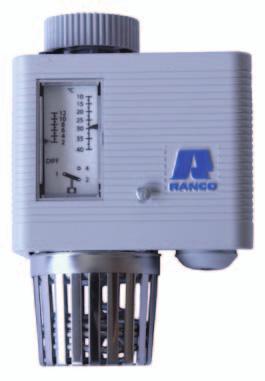
3 2 K series thermostats pplications Ranco K series thermostats are used for temperature control in the commercial refrigeration, residential refrigeration, air conditioning and heating sectors globally. Technical specifications pplication range between -40 C/-40 F and 90 C/194 F (depending on models) Faston terminals 6,3 or 4,8 Electrical rating 6 or 16 at 250V~ (depending on models) Standard mounting or with bracket Capillary lengths from 300 to 3000 mm available, different forms or bulb available vailable in break device version for application with explosive gases (depending on models) pproved by main international bodies K22 K36 K50 / K14 K52 K54 K55 K56 K57 K58 K59 K60 K61 Thermostat with SPDT exchange contact Thermostat with cycling ON-OFF switch (SPST) Thermostat with high rating (16) Thermostat with two sensors Thermostat with signal operation Thermostat with auxiliary OFF Thermostat with quick freeze button Thermostat with constant connection Thermostat with defrost button Thermostat for heating application Thermostat with break device * * * * * * * * * * * * * * * * * * * * * * * * * * * * * * * *
 VS5/VR6 0,1 signal contacts.")
4 K Varifix 53 pplications Varifix thermostats are designed especially to facilitate the replacement of refrigeration controllers on site. The model indicates the typical intended use. Common features Electrical rating: 6 inductive at 250V~ (VW8 16 inductive at 250V~) VS5/VR6 0,1 signal contacts. Model Part number pplication capillary mm cold cut-out cold cut-in warm cut-out specifications warm cut-in defrost signal terminals faston (mm) packaging (pcs/box) VC1 K50P door refrigerator VC101 K50H door refrigerator VC110 K50H1108 bottle refrigerator V2 K50P1174 absorption refrigerator V102 K50H1105 absorption refrigerator VF3 K50P1117 freezer no signal, ice cream cabinet VF103 K50H1106 freezer no signal, ice cream cabinet VP4 K60P door refrigerator with manual defrost VP104 K60L door refrigerator with VP111 K60L2025 manual defrost 2 door refrigerator with manual defrost VS5 K54P1102 freezer with active signal VS105 K54H1404 freezer with active signal VR6 K54P3100 freezer with passive signal VR106 K54H3400 freezer with passive signal (above warm cut-in) (above warm cut-in) (above warm cut-in) (above warm cut-in) VB7 K50P1118 liquid refrigerator, bottle refrigerator VB107 K50H1107 liquid refrigerator, bottle refrigerator VT9 K59L door refrigerator VT93 K59P door refrigerator VI109 K59H door refrigerator VI 112 K59H door refrigerator VW8 K55L5010 air conditioner max diff 3.6 VX0 K59P door refrigerator VG7 K50P1115 soft drinks refrigerator with positive temperatures K VRIFIX - Wiring diagrams VC V VF W VG VW VS5 6 VR6 6 VX0/VT9 Replacement for Larder Refrigerator or 2 Door Cabinet VTD9 Heater Relay Circuit Options (Heater on V2) Control with OFF position for Heat Leakage Defrost Control with OFF using Heater ssisted Defrost Control with Heater & Relay Controlling Compressor and By-pass Valve


5 4 V35-V61 gas valves for refrigerators pplications V35 and V61 controllers are designed especially for use with absorption refrigerators. The V35 is a thermostatic gas valve suitable for use with town gas, natural gas and LPG refrigerant. The V61 is a thermostatic valve that also includes an electric switch, making it suitable for use with gas and electricity. Both controllers are equipped with a permanent by-pass for the pilot function. Technical specifications gas connection: inlet\outlet 1\8" B.S.P.F. or 1\8" NPT electrical connection: 6,35 mm faston (V61 only) by-pass device selectable when placing the order form and length of sensing element selectable when placing the order Dimensions V35 Dimensions V61


6 V85 gas valves for refrigerators 5 pplications V85 controllers are designed especially for use with absorption refrigerators, and are suitable for use with gas and electricity. The V85 is a controller capable of operating as a thermostatic valve, gas safety valve, and thermostat. Technical specifications gas connection: inlet M15 x 1 outlet M10 x 1 electrical connection: 6,35 mm faston (V61 only) Dimensions V85
7 6 Paragon 2001 pplications The Paragon 2001 series of defrost timers are single-cam non-adjustable controllers having factory-set times and cycles, which are designed to operate an SPDT switch. n internal clutch mechanism allows manual adjustment of the first timing/defrost sequence. This same timing/defrost sequence will be repeated as long as the controller remains powered up. Features/dvantages Low noise - Synchronous design ensures extremely quiet operation. Freedom of positioning - The timer can be mounted anywhere, and any way about. Totally enclosed - Patented snap-fit design of closure eliminates the use of external screws or nails. Lightweight - The timer weighs less than 90 grams (0.2 lb imperial). NEM standard terminals- Four male terminals by (0.8 mm by 6.35 mm). Standard connector available. Interchangeability - Standard mounting configuration enables use in all applications. Low Power Consumption - Requires only 2 watts. Double insulated - No earth connection required. Cycle selection tables - (other cycles available) Standard duration of switch transfer in minutes Cycle Minimum Maximum Tolerance 1 hour ± hours ± hours ± hours ± hours ± hours ± 3.0 / ± hours ± 3.0 / ± hours ± 3.0 / ± hours ± hours ± 5.0 Special short duration versions* Cycle Minimum Maximum Tolerance 4 hours ± hours ± hours ± hours ± 1.0 / ± hours ± 1.0 / ± hours ± 1.0 / ± hours ± hours ± 3.0 *contact the sales department
 208-240V (*) 16(8) 208-240V (*) 9(3.6) 208-240V (*) 5(3.")
8 Paragon Electrical specifications C line voltage (+110%/-15%) Power input Electrical output rating 120V 50, 60 or 50/60 Hz V 50 or 60 Hz V 50 or 60 Hz 1/4 W or 2 W 1/3 or 1/2 a 120, V 10 or 15 at 120V 5 at V 125V~ On pilot load 16(6) V (*) 16(8) V (*) 9(3.6) V (*) 5(3.6) V (*) (*) depending on model Technical specifications Cam styles Mounting mbient temperature Recessed Component approved by: Timing motor wiring Low with screwdriver slot, one way rotation Knurled, medium height Knurled, extra height Two 6-20 screws, type 25 Two clearance holes, (4.8 mm) Operation: 0 ºC to 65 ºC Transport: -30 ºC to 70 ºC Suitable for environments with normal pollution levels (*) suitable recess for the device must have reinforced insulation UL and CS EN Neutral to line (shown) Neutral to load Normally Open Neutral to load Normally Closed (*) both in cam-actuator area and for terminals Paragon 2001 series - Dimensions 38.3 (1.51) 17.6 (0.69) 36.5 (1.43) 57.9 (2.28) 50.0 (1.97) 7.9 (0.31) 23.6 (.93) MM 68.6 (INCHES) (2.74) 11.2 (0.44)

9 W35 - SPDT multifunctional thermostat pplications The W35 thermostat automatically opens (hot version) or closes (cold version) the main contact, when the bulb sensing element registers the temperature value, which is set by the knob. When the temperature falls subsequently by the differential value (sdt is 3K), the contact is re-closed (hot version) or re-opened (cold version). The controlled temperature is therefore kept within a minimum fluctuation range. Technical data Contact capacity - hot version: C-1 15(2.5)@250V~ / C-2 2.5(0.4)@250V~ Contact capacity - cold version: C-1 2.5(0.4)@250V~ / C-2 15(2.5)@250V~ Load control: ON-OFF type Temperature variation at bulb: less than 1 C/min Life cycle: 100,000 cycles Minimum current: 200m without gold-plated contacts Maximum temperature: 80 C (body) Maximum bulb temperature: +15% switching load (bulb) Calibration range: see table Dielectric strength: C 2000V 1 min Connections: FSTON 6.3x0.8 - screw Type test standard: Internal thermostat to ENEC03 Enclosure rating: see table Insulation class: I vailable with built-in or remote sensor Part number Description Enclosure rating W3510C0150C00 Wall-mount thermostat -35 C +35 C, with 6.0x112 mm BULB and 1500 mm CPILLRY - NICKEL PLTED IP40 W3510H0150C00 Wall-mount thermostat 0 C +90 C, with 6.0x75 mm BULB and 1500 mm CPILLRY - STINLESS STEEL IP40 W3510H3150C00 Wall-mount thermostat 0 C +120 C, with 6.0x75 mm BULB and 1500 mm CPILLRY - STINLESS STEEL IP40 W3520C0000C00 Wall-mount thermostat -35 C +35 C, with 7.0x95 mm BULB TTCHED IP40 W3520H7000C00 Wall-mount thermostat 0 C +40 C, with 7.0x95 mm BULB TTCHED IP40 W3510C0150C00* Wall-mount thermostat -35 C +35 C, with 6.0x112 mm BULB and 1500 mm CPILLRY - NICKEL PLTED IP54 W3510H0150C00* Wall-mount thermostat 0 C +90 C, with 6.0x75 mm BULB and 1500 mm CPILLRY - STINLESS STEEL IP54 W3510H3150C00* Wall-mount thermostat 0 C +120 C, with 6.0x75 mm BULB and 1500 mm CPILLRY - STINLESS STEEL IP54 W3520C0000C00* Wall-mount thermostat -35 C +35 C, with 7.0x95 mm BULB TTCHED IP54 W3520H7000C00* Wall-mount thermostat 0 C +40 C, with 7.0x95 mm BULB TTCHED IP54 W351NC0150C00 Bare thermostat -35 C +35 C, with 6.0x112 mm BULB and 1500 mm CPILLRY - NICKEL PLTED IP00 W351NH1150C00 Bare thermostat 0 C +90 C, with 6.0x75 mm BULB and 1500 mm CPILLRY - STINLESS STEEL IP00 W351NH3150C00 Bare thermostat 0 C +120 C, with 6.0x75 mm BULB and 1500 mm CPILLRY - STINLESS STEEL IP00 *contact Eliwell sales department W35 - Wiring diagram W35 - Dimensions 44 mm WK351xx 53mm WK352xx 62mm 53mm C C mm 96mm 96mm Thermostat should be earthed 56mm 56mm

10 C17 series thermostats 9 pplications The C17 series of thermostats are two stage devices designed especially for air conditioning applications using stand-alone heat pump appliances and multiple compressor cooling systems. Operating ranges and sensing element dimensions Part number F Dimensions in mm C Capillary Bulb ØxL C x , x x x , x x , x x x 136 C17 - Dimensions 2.56 MX MX SEE NOTE ± MX FLT D D..03 X 45 CHMFER Ø.249± UNC 2B 4 PLCES ± ±.002 FLT ±.008
11 10 J10 Humidity Controls pplications J10 humidity controls are designed to regulate relative humidity in confined spaces by cyclic operation of humidifying or dehumidifying equipment. They are designed for use as internal components in portable humidifiers and dehumidifiers, and as wall mounted humidity controls for central humidification and dehumidification systems. The J10 comprises a relative humidity sensing element, an adjustable set point cam, and an electrical switch. The length of the sensing element varies in response to ambient relative humidity, and the resulting displacement pilots the operation of mechanisms controlling the relative switch contacts. Typical applications Dehumidifiers Humidifiers for products and rooms Fans for confined spaces Processing of materials Central HVC systems Features and options Tough plastic casing with built-in switch Improved woven nylon sensing element guaranteeing speed of response 12 times faster than film type nylon elements. Greater stability of set points, even with significant changes in relative humidity Optimized differential equivalent to 5% RH. Switch grade plastic casing eliminates the need for earth connection Option of 4% RH and 15% RH differentials. Choice between SPST switches (2) and SPDT switches (2) to suit different applications Option of fixed or variable set points vailable with gold plated contacts for microprocessor applications Versions with fixed settings available vailable with box and cover for wall mounting (800 series) Option of electronic controller (contact Ranco Marketing) vailable with built-in or remote sensor Technical Specifications Humidity range Fixed differentials Switch Function of terminals (when present) Switch/casing insulation material: from 10 to 60% RH from 20 to 80% RH from 30 to 90% RH 4% RH or 15% RH SPDT or SPST / Terminals 6.3 x 0.8 mm 1 Closes when RH increases 2 Common 3 Closes when RH decreases, self-extinguishing flame class 94V-0 Comparative tracking index 600 Control cycle rating utomatic switch cycles at 60 C / Manual dial shaft cycles 6000 mbient temperature conditions: Switch head 0 C to 60 C / Shipping -30 C to 65.5 C Casing enclosure rating IP00 Electric shock protection Class 1 Fixing method With screws, or option of snap-fit specified by user


12 J10 Humidity Controls 11 Dial configuration J10 WITHOUT ENCLOSURE ELECTRICL RTING Part number pplication Setting range Switch N terminals Inductive FL Inductive LR Resistive NI J Dehumidification 20% - 80% SPST /3.7 50/ /3.7 J Humidification 20% - 60% SPST /3.7 50/ /3.7 J Dehumidification 20% - 80% SPDT /3.7 50/ /3.7 J and humidification 20% - 80% SPDT / / /1.0 J10 WITH ENCLOSURE ELECTRICL RTING Part number pplication Setting range Switch Inductive FL Inductive LR Resistive NI J Dehumidification 20% - 80% SPST 12.0/3.7 50/ /3.7 J Dehumidification 20% - 80% SPST 12.0/3.7 50/ /3.7 J Humidification 20% - 80% SPDT 12.0/3.7 50/ /3.7 J Humidification 20% - 80% SPST 2.0/ / /1.0 J10 - Dimensions J10 - Wall mounting

13 12 E37 Electronic ice thickness control pplications E37 controls measure the electrical conductivity between a set of electrodes and change the status of the output switch accordingly. They are available in different versions with two or three sensor electrodes and SPDT or SPST relay output contacts. Stainless steel electrodes are used, and there is also the option of specially designed L56 sensors, compatible with E37 controls. The electrodes can be used to measure the thickness of ice or to control the level of liquids. Common features Power consumption: less than 3V mbient operating temperature: 0 C to 60 C Storage temperature: -25 C to 85 C Input/output isolation: 2.5kV Terminal sizes: input 6.3 mm / sensor 4.8 mm vailable with built-in or remote sensor Configuration Relay current Resistance (K ohm) Delay (sec.) Part number pplication Power supply Sensors Relay Ind. Res. Relay cut-in Relay cut-on Diff. Relay cut-in Relay cut-on Certifications E37M ice bank 220V 50 Hz 2 SPST VDE E37M ice bank 220/240V 50 Hz 2 SPST 4 (20 max) E37M ice bank 115V 60 Hz 2 SPST 4 (20 max) CS, UL E37M Liquid level or ice thickness 220/240V 50 Hz 3 SPDT 4 (20 max) \ \ E37M Liquid level or ice thickness 120V 60 Hz 3 SPDT \ \ CS, UL E37 - Wiring diagrams E and 1157 Ice bank E Ice bank or liquid level E and 1204 Liquid level E and 1204 Ice bank differential


14 E37 Electronic ice thickness control 13 E37 - Dimensions MIN MIN Fig 3 Fig 2 TERMINLS 4.8 x 0.8 TERMINLS 6.3 x 0.8 TERMINL 4.8 x 0.8 TERMINLS 6.3 x 0.8 E E and 1157 E and MIN MX L56 - H2001 L56 - H2002 L56 - H mm LEDS 5000 " " " " MIN MX Fig 4 TERMINLS 4.8 x x 0.8 on E TERMINLS 6.3 x 0.8 Fig 5 L56 - H3001 [3000 MM] E and 1204 L56 Sensor ssemblies
15 14 O16-O52 Temperature controls pplications O16 and O52 controls are commercial refrigeration and room thermostats equipped with a single pole SPDT switch, which opens and closes in response to a rise or fall in temperature. Common features The electrical rating of the SPDT single pole switch for all O16 controls is: 16 (16) 250V - normally open or normally closed 1 (1) 250V - opposite side. Storage temperature: -30 C to +55 C Terminals: 1 common; 2 opens the contact when the temperature increases; 4 closes the contact when the temperature increases. Cable entry: O16 Insulating grommet, 14 mm; O52 PG 16 connector Installation: Two threaded holes in the back of the casing to accept M4x6mm screws (supplied) djustment: by means of hex nut incorporating recess for crosshead screwdriver, on both range and differential spindles. n adjustable knob is also available, supplied as standard with certain models. CSING ENCLOSURE RTING STNDRD IP44 (O16): enclosed as in dimensions drawing on page 15 OPTION OF IP66 (O52): enclosed as in dimensions drawing on page 15 mbient air thermostats Part number Measurement range ( C) Upper limit Differential ( C) Lower limit Tube dimensions (mm) O16-H6900 from (-40)-35 to fixed 1.5 fixed diam. 49 max x 43 max O16-H6901 from (-22)-18 to fixed 1.5 fixed diam. 49 max x 43 max O16-H6902 from (-10)-5 to fixed 1.5 fixed diam. 49 max x 43 max O16-H6903 from (+5)+10 to fixed 1.5 fixed diam. 49 max x 43 max O16-H6904 from (-40)-35 to -7 from 1.0 to 6.0 from 3.0 to 12.0 diam. 49 max x 43 max O16-H6905 from (-22)-18 to +13 from 1.0 to 6.0 from 3.0 to 12.0 diam. 49 max x 43 max O16-H6906 from (-10)-5 to +25 from 1.0 to 6.0 from 3.0 to 12.0 diam. 49 max x 43 max O16-H6907 from (+5)+10 to +40 from 1.0 to 6.0 from 3.0 to 12.0 diam. 49 max x 43 max
16 O16-O52 Temperature controls 15 Thermostats with bulb or coiled sensing element Measurement range Differential ( C) Length of capillary Tube dimensions Part number Thermostat type ( C) Upper limit Lower limit including bulb (mm) (mm) O16-H6980 from (-22)-18 to +13 from 1.7 to 7.0 from 3.0 to diam x 140 Cross ambient O16-H6981 from (-10)-5 to +25 from 1.7 to 7.0 from 3.0 to diam x 140 Cross ambient O16-H6982 from (-2)-1 to fixed 1.0 fixed 1830 diam x 140 Cross ambient O16-H6983 from (+5)+10 to +40 from 1.7 to 8.0 from 3.0 to diam x 140 Cross ambient O16-H6930 from (-40)-34 to +32 from 3.0 to 22.0 from 3.0 to diam. 9.5 x 150 Cross ambient O16-H6932 from (+30)+35 to +115 from 2.0 to 14.0 from 2.0 to diam. 9.5 x 150 Cross ambient O16-H6989 from (-10)-5 to +29 from 1.7 to 7.0 from 3.0 to diam x 140 Cross ambient with stop switch O16-H6931 from (-40)-34 to +32 from 3.0 to 22.0 from 3.0 to diam. 9.5 x 150 Cross ambient with stop switch O16-H6921 from (-40)-35 to - 7 from 1.7 to 7.0 from 3.0 to \ Straight capillary O16-H6922 from (-22)-18 to +13 from 1.7 to 7.0 from 3.0 to \ Straight capillary O16-H6924 from (-10)-5 to +25 from 1.7 to 7.0 from 3.0 to \ Straight capillary O16-H6950 from (-40)-35 to - 7 from 1.7 to 7.0 from 3.0 to diam. 9.3 x 38 Coiled capillary O16-H6951 from (-22)-18 to +13 from 1.7 to 7.0 from 3.0 to diam. 9.3 x 38 Coiled capillary O16-H6954 from (-10)-5 to +25 from 1.7 to 7.0 from 3.0 to diam. 9.3 x 38 Coiled capillary O16-H6959 from (-22)-18 to +13 from 1.7 to 7.0 from 3.0 to diam. 9.3 x 38 Coiled capillary with stop switch Lower operating limit: Values in brackets preceding the measurement range indicate minimum lower operating limit values. ccordingly, the range / differential combination must never fall below these values. Differential: The differential does not remain constant across the full measurement range. This is due to the physical properties of the bellows charge gas. Special versions are available. O16 - Dimensions O52 - Dimensions

17 16 O16 Ice bank controls pplications The O16H6999 control is used to determine the thickness of the ice in ice bank chillers. Size and positioning of sensing element CONTROL BULB PISTON FLEXIBLE MEMBRNE TRNSMISSION LIQUID FREEZBLE LIQUID BULB PPROXIMTE ICE LINE FLEXIBLE MEMBRNE SSEMBLE FROM RNCO PT. N EVPORTOR COIL O16 - Dimensions


18 O16-O52 Single pressure controls 17 pplications O16 and O52 instruments are single mechanical pressure switches for high and low pressure, equipped with a single pole switch (SPDT) that closes and opens as the pressure increases or decreases. Common features The electrical rating of the SPDT single pole switch for all O16 controls is: 16 (16) 250Va - normally open or normally closed 1 (1) 250V - opposite side. Storage temperature: -30 C to +55 C Connection to pressure line: 7/16-20 UNF straight male output connector, 1/4 flared female connector Cable entry: O16 Insulating grommet, 14 mm; O52 PG 16 connector Refrigerant: Equipment suitable for use with the more common gases Installation: Two threaded holes in the back of the casing to accept M4x6mm screws (supplied) Terminals: 1 common, 2 opens when the pressure increases, 4 closes when the pressure increases. CSING ENCLOSURE RTING: STNDRD IP44 (O16): enclosed as in O16 dimensions drawing OPTION OF IP66 (O52): enclosed as in O52 dimensions drawing Operating and safety pressures Models and Features Bellows type Maximum stationary pressure (bar) Burst Pressure (bar) Low Pressure High Pressure Part number High or Low Reset TÜV (safety) Measurement range PSI (bar) Differential PSI (bar) Bellows type O16-H6703 low automatic 10" ( ) ( ) standard 7/16" - 20 UNF male Connection O16-H6704 low automatic 10" ( ) ( ) standard braze welded tube diam. 6 mm L.100 mm O16-H6713 low automatic 10" ( ) ( ) standard 1000 mm capillary with 1/4" SE nut O16-H6705 low manual ( ) 9 (0.6) standard 7/16" - 20 UNF male O16-H6750 high automatic ( ) (2...8) standard 7/16" - 20 UNF male O16-H6763 high automatic ( ) (2...8) TUV braze welded tube diam. 6 mm L.100 mm O16-H6751 high manual ( ) 45 (3.2) standard 7/16" - 20 UNF male O16-H6758 high automatic ( ) (3...8) TUV 7/16" - 20 UNF male O16-H6759 high manual* ( ) 45 (3.2) TUV 7/16" - 20 UNF male O16-H6764 high manual ( ) 45 (3.2) TUV braze welded tube diam. 6 mm L.100 mm O16-H6760 high manual** ( ) 45 (3.2) TUV 7/16" - 20 UNF male O16-H6765 high manual ( ) 45 (3.2) TUV braze welded tube diam. 6 mm L.100 mm * reset without removing cover ** reset with removal of cover O16 - Dimensions O52 - Dimensions
19 18 O17 Double pressure controls pplications O17 instruments are double mechanical pressure switches for high or low pressure, equipped with a single pole switch (SPDT) that opens and closes in response to a rise or fall in pressure. Common features Electrical rating of single pole SPDT switch 16 (16) 250V - normally open or normally closed (except in the case of the dual signal version) 1 (1) 250V - opposite side. mbient temperature -30 C to +55 C Connection to pressure line 7/16-20 UNF straight male output connector, 1/4 flared female connector Cable entry 14mm insulating grommet Refrigerants Equipment suitable for use with the more common gases. Installation Two threaded holes in the back of the casing to accept M4x6mm screws (supplied) Standard O17 terminals 1 common, 2 opens when low pressure increases and opens when high pressure increases. O17 dual signal terminals 1 common, 2 closes signal circuit when low pressure decreases, 3 closes signal circuit when high pressure increases, 4 closes when low pressure increases and opens when high pressure increases. O17 version with dual signal terminals 1 and 4 as above, terminals (1 and 2) and (1 and 3): V Operating and safety pressures Bellows type Maximum stationary pressure (bar) Burst Pressure (bar) Low Pressure High Pressure TÜV (safety) Models and Features Reset Measurement range PSI (bar) Differential PSI (bar) Part number High Low High Low High Low Bellows type Connection Switch O17-H4701 automatic automatic " /16"-20 UNF 50 (3.5) ( ) standard (7...30) ( ) male dual signal O17-H4702 automatic automatic " braze welded tube 50 (3.5) ( ) standard (7...30) ( ) Ø 6 mm - L 100 mm dual signal O17-H6701 automatic automatic " /16"-20 UNF 50 (3.5) ( ) standard (7...30) ( ) male O17-H4703 manual manual " /16"-20 UNF 50 (3.5) 9 (0.6) standard (7...30) ( ) male dual signal O17-H4704 manual manual " braze welded tube 50 (3.5) 9 (0.6) standard (7...30) ( ) Ø 6 mm - L 100 mm dual signal O17-H4713 manual manual " mm capillary 50 (3.5) 9 (0.6) standard (7...30) ( ) with 1/4" SE nut dual signal O17-H4705 manual automatic " /16"-20 UNF 50 (3.5) ( ) standard (7...30) ( ) male dual signal O17-H4706 manual automatic " braze welded tube 50 (3.5) ( ) standard (7...30) ( ) Ø 6 mm - L 100 mm dual signal O17-H4715 manual automatic " mm capillary 50 (3.5) ( ) standard (7...30) ( ) with 1/4" SE nut dual signal O17-H6705 manual automatic " /16"-20 UNF 50 (3.5) ( ) standard (7...30) ( ) male O17-H4758 automatic automatic " /16"-20 UNF 58 (4) ( ) TUV (7...30) ( ) male dual signal O17-H4763 automatic automatic " braze welded tube 58 (4) ( ) TUV (7...30) ( ) Ø 6 mm - L 100 mm dual signal O17-H4759 manual* automatic " /16"-20 UNF 58 (4) ( ) TUV (7...30) ( ) male dual signal O17-H4760 manual** automatic " /16"-20 UNF 58 (4) ( ) TUV (7...30) ( ) male dual signal O17-H4764 manual automatic " braze welded tube 58 (4) ( ) TUV (7...30) ( ) Ø 6 mm - L 100 mm dual signal O17-H6759 manual automatic " /16"-20 UNF 58 (4) ( ) TUV (7...30) ( ) male O17-H6764 manual automatic " /16"-20 UNF 58 (4) ( ) TUV (7...30) ( ) male O17-H6703 manual manual " /16"-20 UNF 50 (3.5) 9 (0.6) standard (7...30) ( ) male * reset without removing cover ** reset with removal of cover
 Flat mounting bracket 31696-1 (2) ngle mounting bracket 3200115-1 (3) Knob 6309138-1 (2301742-1) (4) 1000 mm capillary")
20 O17 Double pressure controls 19 O17 - Dimensions MX MX x M4 MOUNTING SCREWS 117 MX /16-20 UNF ER TH SCREW M4 7/16-20 UNF GR OMMET Ø6.5 - Ø ccessories for O series controls Part number Description (1) Flat mounting bracket (2) ngle mounting bracket (3) Knob ( ) (4) 1000 mm capillary with 7/16" fittings, without valve opener ( ) (4) 1500 mm capillary with 7/16" fittings, without valve opener (5) Screw with clearance hole
21 20 G60 - G63 Fixed setting pressure switches pplications The G60/63 range of pressure switches are designed to protect refrigeration systems against critical conditions by setting high and low pressure limits. The G60 low pressure switch protects the compressor against low suction pressures where there is a danger of liquid refrigerant entering the compressor and causing damage. The G63 high pressure switch protects the system against excessive delivery pressures, which can be dangerous and cause expensive damage to equipment. Technical Specifications Differential setting fitting, see graphs Refrigerants Compatible with all non corrosive refrigerants and gases mbient temperature - switch head -30 C to +55 C Maximum compressor head temperature 135 C Storage and transport temperature limits -30 C to +70 C Switch S.P.D.T. or S.P.S.T. a) 6 (6) 250V; Electrical rating b) 10FL (40LR) at 120V ~ when used as S.P.S.T. on both contacts; c) 10FL (40LR) at 120V load ~ 1 (1) on opposite contact when used as S.P.D.T.; d) 5 at 14V dc (inductive) Terminal 1 Common. Switch markings Terminal 2 Break on pressure rise Terminal 4 Break on pressure drop Enclosure rating IP00 IP44 IP66 G60 LOW PRESSURE Operating range: fixed within limits of - 10"Hg vacuum (-0.35 bar) to 100 psi (7 bar) cut out; 160 psi (11 bar) cut in Reset mode: automatic reset. Manual reset for cut-out on pressure drop only Pressure range Tolerance Differential Tolerance TÜV V~ - 75 psi ± 2 psi 7-15 psi ± 3 psi V~ - 75 psi ± 2 psi psi ± 4 psi psi ± 4 psi psi ± 7 psi G63 HIGH PRESSURE Operating range: fixed within limits of PSI (31 bar) to 100 psi (7 bar) cut out; 75 psi (5.2 bar) cut in Reset mode: automatic reset. Manual reset for cut-out on pressure rise only Pressure range Tolerance Differential Tolerance TÜV psi ± 4 psi psi ± 7 psi Yes psi ± 4 psi psi ± 10 psi Yes psi ± 6 psi psi ± 14 psi Yes psi ± 10 psi psi ± 14 psi Yes psi ± 10 psi psi ± 16 psi Yes G60 G60 - G63 TÜV BR (REF.) BR (REF.) DIFFERENTIL (PSI) BR (REF.) DIFFERENTIL (PSI) Possible Differential with G63 Syandard Version Possible Differential 8 with G63/G63 TÜV 100 Versions BR (REF.) CUT OUT PRESSURE (PSIG) CUT OUT PRESSURE (PSIG)
 1015 PSI (70 bar) G60 0.1 / 0.15 510 PSI (35 bar) 2030 PSI (140 bar) G63 0,15 510 PSI (35 bar) 2030 PSI (140 bar) TÜV (safety) 0.")
22 G60 - G63 Fixed setting pressure switches 21 Features and options Type Diaphragme thickness (mm) Maximum stationary pressure PSI (bar) Burst Pressure PSI (bar) G PSI (20 bar) 1015 PSI (70 bar) G / PSI (35 bar) 2030 PSI (140 bar) G63 0, PSI (35 bar) 2030 PSI (140 bar) TÜV (safety) / 675 PSI (47 bar) ccessories kits Part Number Type Notes uto reset Without guide plate uto reset Without guide plate Manual reset Without guide plate Manual reset Without guide plate G60 - G63 - Dimensions G60 - G63 - Pressure connections Manual or auto reset with Guide Plate TYPE PRESSURE CONNECTIONS TYPE : 7/16" - 20 UNF female TYPE D: 1/4" x 150 mm brazed fitting with seal TYPE E: 1/8" x 27NPT Male TYPE D TYPE E Standard auto reset G60 - G63 - Wiring diagrams Cycle interruption in the event of low pressure Cycle interruption in the event of high pressure

23 22 SnapDisk - Fixed setting pressure switches pplications The SnapDisk Pressure switches are designed to protect refrigeration systems against critical conditions by setting high and low pressure limits. The low pressure switch protects the compressor against low suction pressures where there is a danger of liquid refrigerant entering the compressor and causing damage. The high pressure switch protects the system against excessive delivery pressures, which can be dangerous and cause expensive damage to equipment. Technical data Pressure fittings Electrical connections Pressure range Service life 1/4" SE female with valve opener 1/8" NPT male 1/4" NPT male 1/4" Tube 3/32" Capillary tube 1/4" (6.35 mm) Faston connectors 3/16" (4.8 mm) Faston connectors Wires (stripped ends or terminals) - different lengths djustments: bar HR: 100,000 cycles HL: 6,000 cycles HC: 250,000 cycles (contact sales department) Operating temperature range C Switch logic at standard atmospheric pressure - 0 bar Normally Open (NO): - closes when pressure increases Normally Closed (NC) - opens when pressure increases SPDT - open/close on pressure increase/decrease FL: Nominal current LR: Starting current Electrical specifications - HR and HL series 5-28 Vdc Volts (a.c.) FL FR / Electrical specifications - HC series 5-28 Vdc Volts (a.c.) FL FR /
24 SnapDisk - Fixed setting pressure switches 23 Dimensions:

 C.O.P.D. factory setting C.I.P.D. minus C.O.P.D. Capillary+flare nut (+/-50mm) P30 3601 60 +\-15 0,7-4 (10-60) adj. 0,7 (10) 0.")
 0.5 (7) max 914mm P30 5826 120 +\-20 0.6 (9) fixed 0.6 (9) fixed 0.5 (7) max 914mm P30 5827 120 +\-20 0.6 (9) fixed 0.6 (9) fixed 0.5 (7) max 1\4 SE P30 5839 120 +\-20 0.6 (9) fixed 0.6 (9) fixed 0.5 (7) max 1\4 SE P30 5842 120 +\-20 0.")
25 OPERTING 24 P30 - Differential pressure switches for Oil pplications The P30 oil differential pressure switch is designed for use with compressors in refrigeration systems that use external oil pumps with refrigerants. It protects the compressor against loss of lubricating oil pressure, which could otherwise cause serious bearing damage resulting ultimately in breakdown of the compressor. Connected to the crankcase and oil pump by capillaries, the P30 pressure switch detects the difference between pressure in the crankcase and pressure on the outlet side of the oil pump. Model Delay C.O.P.D. range Pressure - bar (psig) C.O.P.D. factory setting C.I.P.D. minus C.O.P.D. Capillary+flare nut (+/-50mm) P \-15 0,7-4 (10-60) adj. 0,7 (10) 0.5 (7) max 914mm Fitting male flare P \-20 0,7-4 (10-60) adj. 0,7 (10) 0.5 (7) max 914mm P \-20 0,7-4 (10-60) adj. 0,7 (10) 0.5 (7) max 1\4 SE P \-20 0,7-4 (10-60) adj. 0,7 (10) 0.5 (7) max 914mm P \ (9) fixed 0.6 (9) fixed 0.5 (7) max 914mm P \ (9) fixed 0.6 (9) fixed 0.5 (7) max 1\4 SE P \ (9) fixed 0.6 (9) fixed 0.5 (7) max 1\4 SE P \ (9) fixed 0.6 (9) fixed 0.5 (7) max 914mm P \ (9) fixed 0.6 (9) fixed 0.5 (7) max 1\4 SE Terminology The main function of the differential pressure switch is to detect the difference between pressure in the crankcase and pressure on the outlet side of the oil pump. When this value is below the preset value known as the cut-out pressure differential (C.O.P.D.) the compressor will shut off automatically. Oil pump pressure (O.P.P.): the pressure generated by the oil pump Case pressure (C.P.): pressure internally of the compressor Effective oil pressure (E.O.P.): Cut-out differential Cut-out pressure differential (C.O.P.D.): difference in pressure between O.P.P. and C.P.. at this value, the time delay relay is activated to shut off the system Cut-in pressure differential (C.I.P.D.): difference in pressure between O.P.P. and C.P.: at this value, the time delay relay is deactivated, allowing the system to restart Pressure difference (P.D.): C.I.P.D. minus C.O.P.D. P30 - Wiring diagrams - pplications 2 p L RESET M 120 * 240 P30 N JUMPER P L BIMETL HETER RESET M 120 * 240 * P30 CONTROL 1 BIMETL HETER CONTROL 3 COMPRESSOR CONTCTOR COMPRESSOR CONTCTOR OPERTING CONTROL L1 L2 L3 L N P30 - Dimensions P30 - Installation
26 RK30 Oil control unit 25 pplications The RK30 control unit monitors the level of oil in the compressor by way of an optoelectronic sensor so as to prevent operation without lubricant and effectively prolong the service life of the compressor. The unit incorporates a solenoid valve for automatic replenishment of the oil, and an alarm relay output (factory-set to generate an alarm or stop the compressor by means of an external power relay). Technical data Supply voltage Operating current Electrical connection 24 V~ ±10% 50/60Hz 30V for each RK30 (when using the standard coil) 9.4mm Industry Standard connectors Connector EN Relay output Contact data Materials used in manufacture NO and NC free contact output up to The NO alarm contact (blue wire) is closed when the RK30 is powered up. nickel-plated steel Enclosure rating IP 65 Storage temperature -40 C / +60 C Oil temperature -40 C / +85 C mbient operating temperature -40 C / +60 C Maximum operating pressure MOPD Oil injector fitting 45 bar (up to 60 bar on request) 45 bar (up to 60 bar on request) 7/16-20 UNEF male Cable type PVC - CEI Cable operating temperature C (in fixed position) Electrical connections Electronic sensor connections (Industry Std 9.4 mm), viewed from above. The arrow indicates the side on which the oil level sight glass is located; the loose end of 90 connector emerges on the side opposite. - Power supply - (cable with 2 wires and valve branch) 2: Brown (24V~) 3: Blue (24V~) B - larm relay - (3 core cable) 1: Brown (closed in alarm state) 2: Blue (open in alarm state) 3: Black: (common) Solenoid valve connections EN (EX DIN size ). The coil is connected between pins 1 and 2, and in the wiring harness supplied, it is suitably connected to connector of the optoelectronic sensor.

27 26 RK30 Oil control unit pplication and part numbers pplication Part Number Description RK optical oil regulator 45bar 24V~ no adapter stand alone RK optical oil regulator 45bar 24V~ no adapter stand alone RK optical oil regulator 45bar 24V~ 1 1\8" UNEF stand alone FREON RK optical oil regulator 45bar 24V~ 1 1\8" UNEF stand alone RK optical oil regulator 45bar 24V~ 3\4" NPT stand alone RK optical oil regulator 45bar 24V~ 3\4" NPT stand alone RK optical oil regulator 45bar 24V~ 3/4/6-hole flange stand alone RK optical oil regulator 45bar 24V~ 3/4/6-hole flange stand alone CO 2 RK optical oil regulator 60bar 24V~ 3/4/6-hole flange stand alone RK optical oil regulator 60bar 24V~ 3/4/6-hole flange stand alone pplication Kit part numbers Part numbers included Description RK optical oil regulator 45bar 24V~ no adapter stand alone FREON FREON RK K0 RK K0 RK30C power supply \ valve cable assembly 3 m RK30CB alarm cable 3 m RK FLNGE DPTER 3/4/6 HOLES RK DPTER 1-1/8" 18 UNEF RK DPTER 3/4" NPT RK optical oil regulator 45bar 24V~ no adapter stand alone RK30C power supply \ valve cable assembly 3 m RK30CB alarm cable 3 m RK FLNGE DPTER 3/4/6 HOLES RK DPTER 1-1/8" 18 UNEF RK DPTER 3/4" NPT ccessories Part number RK30C RK30CB RK30C RK30CB RK RK RK TF Description Power cable 3 m larm cable 3 m Power cable 6 m larm cable 6 m adapter 1-1/8" 18 UNEF adapter 3/4" NPT adapter 3/4/6 holes Transformer 24\230V 35Va protected

28 F V series reversing valves 27 E F D F pplications controlled space by The 4-way reversing valve is the key component in systems able to provide heating and cooling in a climate reversing the flow direction of the refrigerant. It is used for room air conditioning, central air conditioning systems and packaged S the units. Reversing valves are designed for heat pump systems with capacities from 3 kw up to 580 kw. They are suitable for pressure drop majority of refrigerants, such as R407C - R410 - R134. The design of the valve also guarantees minimum and very low risk of leakage. The available models offer numerous different types of connections, configurations and capacities for specific applications. Standard models are available in small quantities per box for greater flexibility of purchasing and use. D F V series - Part numbers and technical data Part Number V V V V V V V V V V V V V3-4100H0700 V V V V V V V V V V V V V M0200 V V V V T0200 R407C kw min/max (US ton min/ max) R410 kw min/max (US ton min/ max) R134 kw min/max (US ton min/ max) 1.34 / 3.02 (0.38 / 0.86) 1.41 / 4.57 (0.40 / 1.30) 1.41 / 4.57 (0.40 / 1.30) 1.41 / 4.57 (0.40 / 1.30) 1.41 / 4.57 (0.40 / 1.30) 1.41 / 4.57 (0.4 / 1.3) 1.41 / 4.57 (0.4 / 1.3) 2.81 / 6.33 (0.8 / 1.8) 2.81 / 6.33 (0.8 / 1.8) 3.87 / 7.03 (1.1 / 2.0) 3.87 / 7.03 (1.1 / 2.0) 3.87 / 9.50 (1.1 / 2.7) 3.87 / 9.50 (1.1 / 2.7) 3.87 / 9.85 (1.1 / 2.8) 3.87 / (1.1 / 5.4) 3.87 / (1.1 / 5.4) 3.87 / (1.1 / 5.4) 3.87 / (1.1 / 5.4) / (3.2 / 9.4) / (3.2 / 9.4) / (3.2 / 9.4) / (3.2 / 10.7) / (3.2 / 10.7) / (3.2 / 9.4) / (4.9 / 9.4) / (4.9 / 10.7) / (4.9 / 10.7) / (4.9 / 10.7) / (4.9 / 10.7) / (6.5 / 13.3) 1.55 / 3.83 (0.44 / 1.09) 1.76 / 5.98 (0.50 / 1.70) 1.76 / 5.98 (0.50 / 1.70) 1.76 / 5.98 (0.50 / 1.70) 1.76 / 5.98 (0.50 / 1.70) 1.76 / 5.98 (0.50 / 1.70) 1.76 / 5.98 (0.50 / 1.70) 3.17 / 7.74 (0.90 / 2.20) 3.17 / 7.74 (0.90 / 2.20) 4.57 / 8.79 (1.30 / 2.50) 4.57 / 8.79 (1.30 / 2.50) 4.57 / (1.30 / 3.40) 4.57 / (1.30 / 3.40) 4.57 / (1.30 / 3.50) 4.57 / (1.30 / 6.80) 4.57 / (1.30 / 6.80) 4.57 / (1.30 / 6.80) 4.57 / (1.30 / 6.80) / (3.70 / 11.90) / (3.70 / 11.90) / (3.70 / 11.90) / (3.70 / 13.50) / (3.70 / 13.50) / (3.70 / 11.90) / (5.61 / 11.90) / (5.61 / 13.50) / (5.61 / 13.50) / (5.61 / 13.50) / (5.61 / 13.50) / (7.50 / 16.75) 1.16 / 2.36 (0.33 / 0.67) 1.41 / 3.87 (0.40 / 1.10) 1.41 / 3.87 (0.40 / 1.10) 1.41 / 3.87 (0.40 / 1.10) 1.41 / 3.87 (0.40 / 1.10) 1.41 / 3.87 (0.4 / 1.1) 1.41 / 3.87 (0.4 / 1.1) 2.46 / 4.92 (0.7 / 1.4) 2.46 / 4.92 (0.7 / 1.4) 3.17 / 5.63 (0.9 / 1.6) 3.17 / 5.63 (0.9 / 1.6) 3.17 / 7.39 (0.9 / 2.1) 3.17 / 7.39 (0.9 / 2.1) 3.17 / 7.74 (0.9 / 2.2) 3.17 / (0.9 / 4.2) 3.17 / (0.9 / 4.2) 3.17 / (0.9 / 4.2) 3.17 / (0.9 / 4.2) 9.85 / (2.8 / 7.4) 9.85 / (2.8 / 7.4) 9.85 / (2.8 / 7.4) 9.85 / (2.8 / 8.4) 9.85 / (2.8 / 8.4) 9.85 / (2.8 / 7.4) / (4.1 / 7.4) / (4.1 / 8.4) / (4.1 / 8.4) / (4.1 / 8.4) / (4.1 / 8.4) / (5.4 / 10.5) Tube sizes (C.T.S.) Suction (C.) Delivery Style Coil mm inches / /16 B / / / / / / / / / /16 B / /8 B / / / /8 B / /8 c / /8 D / /2 E / O.D. 1/2 O.D. E / /2 E / / / / / / / / / / / / / / / / / / / / / / / O.D. 3/4 O.D / / / / / / / /8 O.D. O.D. F mm inches Weight (g) Standard (without packaging coil) LEGEND - : High Pressure: S: Suction; : Connected to high pressure when solenoid is energized B D F B B B B B B B D B D D D D D D D B BF F F F F F E C E S C E S C C C E C S C C C S S S SC S S S E E C E E E E
29 28 N series reversing valves pplications The 4-way reversing valve is the key component in systems able to provide heating and cooling in a climate controlled space by reversing the flow direction of the refrigerant. It is used for room air conditioning, central air conditioning systems and packaged units. Reversing valves are designed for heat pump systems with capacities from 3 kw up to 580 kw. They are suitable for the majority of refrigerants, such as R407C - R410 - R134. The design of the valve also guarantees minimum pressure drop and very low risk of leakage. The available models offer numerous different types of connections, configurations and capacities for specific applications. Standard models are available in small quantities per box for greater flexibility of purchasing and use. N series - Part numbers and technical data Part Number R407C kw min/max (US ton min/ max) R410 kw min/max (US ton min/ max) R134 kw min/max (US ton min/ max) Tube sizes (C.T.S.) Suction (C.) Delivery mm inches mm inches Style Weight (g) Standard (without packaging coil) Coil N15C00S * N20C00G * N20C10G N20C01G * N20C11G N30C00G * N30C10G N40C10G N50C10G N60C10G / (4.50 / 15.50) / (5.00 / 20.60) / (5.00 / 20.60) / (5.00 / 20.60) / (5.00 / / (7.50 / 30.90) / (7.50 / 30.90) / (10.00 / 41.20) / (10.00 / 51.50) / (15.10 / 55.60) / (4.50 / 17.50) / (5.00 / 23.20) / (5.00 / 23.20) / (5.00 / 23.20) / (5.00 / 23.20) / (7.51 / 34.80) / (7.51 / 34.80) / (10.01 / 46.40) / (10.01 / 58.00) / (15.10 / 70.00) / (3.50 / 11.60) / (3.90 / 15.40) / (3.90 / 15.40) / (3.90 / 15.40) / (3.90 / 15.40) / (5.80 / 23.10) / (5.80 / 23.10) / (7.70 / 30.80) / (7.70 / 38.50) / (10.00 / 44.10) / / / / / / / / / / / / / / / / / / NOTE: capacities indicated are based on the following conditions: evaporation temperature: 7.2 C; sub cooling: 5.0 C; condensation temperature: 54.4 C; superheat: 5.0 C; pressure drop: MPa * Without mounting brackets V-N Reversing valve operating specifications Min pressure Δ to reverse 0.15 MPa Max pressure Δ to reverse 3.04 MPa Max operating pressure 4.68 MPa (V series) / 4.17 MPa (N series) Min burst pressure MPa (V series) / 16.7 MPa (N series) Max operating temperature 121 C Min operating voltage 85% of rated voltage Max operating voltage 110% of rated voltage LEGEND - : High Pressure: S: Suction; : Connected to high pressure when solenoid is energized

30 VH series reversing valves 29 pplications The 4-way reversing valve is the key component in systems able to provide heating and cooling in a climate controlled space by reversing the flow direction of the refrigerant. It is used for air conditioning in rooms, central air conditioning systems and packaged units. Reversing valves are designed for heat pump systems with capacities from 3 kw up to 580 kw. They are suitable for the majority of refrigerants, such as R407C - R410 - R134. The design of the valve also guarantees minimum pressure drop and very low risk of leakage. The available models offer numerous different types of connections, configurations and capacities for specific applications. Standard models are available in small quantities per box for greater flexibility of purchasing and use. VH series - Part numbers and technical data Part Number R407C kw min/max (US ton min/max) R410 kw min/max (US ton min/max) R134 kw min/max (US ton min/max) Tube sizes (C.T.S.) Suction (C.) Delivery mm inches mm inches Weight (g) (without coil) Standard packaging Coil VH / (20.00 / 82.40) / (15.40 / 61.60) / (15.40 / 61.60) Flange RBK 65 Flange RBK 65 Flange RBK 50 Flange RBK VH / (30.00 / ) / (23.10 / 92.40) / (23.10 / 92.40) Flange RBK 65 Flange RBK 65 Flange RBK 50 Flange RBK VH / (40.00 / ) / (30.80 / ) / (30.80 / ) Flange RBK 65 Flange RBK 65 Flange RBK 50 Flange RBK NOTE: capacities indicated are based on the following conditions: evaporation temperature: 7.2 C; sub cooling: 5.0 C; condensation temperature: 54.4 C; superheat: 5.0 C; pressure drop: MPa VH Reversing valve operating specifications Min pressure Δ to reverse 0.34 MPa Max pressure Δ to reverse 2.25 MPa Max operating pressure 3.3 MPa Min burst pressure 16.5 MPa Max operating temperature 120 C Min operating voltage 85% of rated voltage Max operating voltage 110% of rated voltage LEGEND - : High Pressure: S: Suction; : Connected to high pressure when solenoid is energized


31 30 LDK - LDL Coils pplications RNCO LDL and LDK solenoid coils are now compatible with the entire range of RNCO reversing valves. LDL and LDK magnetic coils are epoxy encapsulated, resistant to moisture and use minimal energy. Coils are colour coded for easy identification of the different input voltages available. LDK coils - Part numbers and technical specifications Coil Colour Power supply Frequency Power Cable length UL classification 50/60Hz mm inches LDK-11 Red 24V~ 50/60Hz 5/ LDK-31 Black 120V~ 50/60Hz 5/ LDK-41 Green 208 / 240V~ 50/60Hz 5/ LDK-73 Yellow 12Vc - 10 F LDK-83 Orange 24Vc - 10 F The LDK coil includes a W29 wiring harness with 1200 mm leads Other cable lengths available on request LDL coils - Part numbers and technical specifications Coil Colour Power supply Frequency Power Cable length UL classification 50/60Hz mm inches LDL-11 Red 24V~ 50/60Hz 5/ LDL-41 Green 208 / 240V~ 50/60Hz 5/ LDL-41 Green 208 / 240V~ 50/60Hz 5/ Other cable lengths available on request
32 0DS PXV Pulse expansion valve 31 pplications The PXV solenoid operated expansion valve controls the flow of refrigerant to the evaporator by modulating the opening time of the valve element, allowing a wide range of power variation. Highly precise and reliable control of refrigerant flow increases the efficiency of the entire system. There are 9 interchangeable orifices available, with power ratings from 1 kw to 24 kw. This valve must be piloted by a V800 electronic driver. The typical application is in refrigeration systems, especially refrigerated counter displays of the kind used in supermarkets. PVX - Technical data Voltage tolerance (Vac) +6/-10% IEC Enclosure rating Operating principle djustment range (capacity range) Minimum operating time Capacity (R404) IP65; IP68 Pulse Width Modulation 6 seconds 1 second 15 kw djustment range (capacity range) % Braze welded connections TS temperature C mbient temperature C Leakage from valve seat Minimum open pressure differential (minopd) Maximum open pressure differential (MOPD) Maximum operating pressure Burst Pressure Certifications PED 3/8" 1 / 2", 10 mm - 12 mm, 1 / 2" 5/8", 12 mm 16 mm <1cc/min <0.003 of kv value 0 bar 18 bar 45 bar 330/250 bar 97/23/EC Category II art.3.3 General coil specifications Coil type Eliwell part number Voltage (V~) Voltage tolerance (%) Frequency (Hz) Power (W) Power consumption Start (50Hz) Operation (50Hz) Insulation class Maximum temperature Windings ( C) PXV PXVB0R / / F PXV PXVB0R / / / F PXV CO 2 PXVE0R / / / F mbient ( C) Electrical connections connector DIN part number PXVB0R Enclosure rating standard IP65 (for IP68 contact the sales department) Orifices 1 to 6 Orifices 7 to M10 0DS M12 0DS M12 51 M16 0DS 53
33 32 PXV Pulse expansion valve General specifications and capacities of valves (common refrigerants) ODS connections Capacity (kw) Part Number Orifice type Orifice hole (mm) (in) (mm) Refrigerant IN OUT IN OUT PXVB03S /8" 1/2" PXVBM10S Flow factor Kv (m3/h) R22 R134a R404 - R507 R407C R PXVB03S /8" 1/2" PXVBM10S PXVB03S /8" 1/2" PXVBM10S PXVB03S /8" 1/2" PXVBM10S PXVB03S /8" 1/2" PXVBM10S PXVB03S /8" 1/2" PXVBM10S PXVB04S /2" 5/8" PXVBM12S PXVB04S /2" 5/8" PXVBM12S PXVB04S /2" 5/8" PXVBM12S Rated capacities are referred to: Evaporation temperature Tevap = +5 C Condensation temperature Tcond = +32 C Liquid temperature at valve inlet Tliq = +28 C
34 PXV Pulse expansion valve 33 General specifications and capacities of CO ² valves (R744) ODS connections Capacity (kw) (in) (mm) Refrigerant Part Number Orifice type Orifice hole (mm) IN OUT IN OUT PXVE03S /8" 1/2" PXVEM10S PXVE03S /8" 1/2" PXVEM10S PXVE03S /8" 1/2" PXVEM10S PXVE03S /8" 1/2" PXVEM10S PXVE03S /8" 1/2" PXVEM10S PXVE03S /8" 1/2" PXVEM10S PXVE03S /2" 5/8" PXVEM10S Flow factor Kv (m³/h) R General specifications and capacities of R290 valves ODS connections Capacity (kw) (in) (mm) Refrigerant Part Number Orifice type Orifice hole (mm) IN OUT IN OUT PXVV03S /8" 1/2" PXVVM10S PXVV03S /8" 1/2" PXVVM10S PXVV03S /8" 1/2" PXVVM10S PXVV03S /8" 1/2" PXVVM10S PXVV03S /8" 1/2" PXVVM10S PXVV03S /8" 1/2" PXVVM10S PXVV04S /2" 5/8" PXVVM12S PXVV04S /2" 5/8" PXVVM12S PXVV04S /2" 5/8" PXVVM12S Rated capacities are referred to: Evaporation temperature Tevap = +5 C Condensation temperature Tcond = +32 C Liquid temperature at valve inlet Tliq = +28 C Flow factor Kv (m³/h) R

35 34 PXV Pulse expansion valve PXV valves orifice kits Part Number Description Refrigerants Coils and connectors Part Number Description Refrigerants PXVB0R N 1 orifice kit PXVE0R60000 CO ² EEV COIL 220/230 V~ R744 PXVB0R PXVB0R PXVB0R PXVB0R PXVB0R PXVB0R PXVB0R N 2 orifice kit N 3 orifice kit N 4 orifice kit N 5 orifice kit N 6 orifice kit N 7 orifice kit N 8 orifice kit R22, R134a, R404, R407C, R410, R507 PXVB0R60000 EEV COIL 220/230 V~ PXVB0R20000 EEV COIL 24 V~ R290, R22, R134a, R404, R407C, R410, R507 R290, R22, R134a, R404, R407C, R410, R507 PXVB0R N 9 orifice kit PXVB0R EEV COIL CONNECTOR IP65 ll PXVE0R N 1 orifice kit - CO ² PXVE0R N 2 orifice kit - CO ² PXVE0R N 3 orifice kit - CO ² PXVE0R N 4 orifice kit - CO ² R744 PXVE0R N 5 orifice kit - CO ² PXVE0R N 6 orifice kit - CO ² PXVE0R N 7 orifice kit - CO ² PXVV0R PXVV0R PXVV0R PXVV0R PXVV0R PXVV0R PXVV0R PXVV0R PXVV0R N 1 orifice kit - R290 N 2 orifice kit - R290 N 3 orifice kit - R290 N 4 orifice kit - R290 N 5 orifice kit - R290 N 6 orifice kit - R290 N 7 orifice kit - R290 N 8 orifice kit - R290 N 9 orifice kit - R290 R290 Orifice kits Coils and connectors - dimensions : O-ring 2: Lock nut 3: O-ring 4: Orifice 63mm 41mm 35mm 1 2 1: Seal 2: Connector securing screw max torque 0.8 Nm
 0...10 bar (absolute) 0...30 bar (absolute) 0.")
36 EWP Pressure transducers 35 pplications Pressure transducers or probes of the EWP series are sensors that transmit a signal by way of a current output to the measuring instruments with which they are connected. General specifications EWP007 EWP010 EWP030 EWP050 Operating range bar (absolute) bar (absolute) bar (absolute) bar (absolute) Output signal 2 wires m 2 wires m 2 wires m 2 wires m Overload 2 times pressure range 2 times pressure range 2 times pressure range 2 times pressure range Power supply Volts Volts Volts Volts ccuracy ± 0.5 % FS max (linearity, hysteresis, repeatability) ± 0.5 % FS max (linearity, hysteresis, repeatability) ± 0.5 % FS max (linearity, hysteresis, repeatability) Compensated temperature C C C C Electrical connections 2 m cable, wired 2 m cable with PCKRD connector 2 m cable, wired 2 m cable with PCKRD connector 2 m cable, wired 2 m cable with PCKRD connector mpm connector ± 0.5 % FS max (linearity, hysteresis, repeatability) 2 m cable, wired 2 m cable with PCKRD connector Mechanical connections male connector / female connector ¼ SE (7/16"-20UNF) male connector / female connector ¼ SE (7/16"-20UNF) male connector / female connector ¼ SE (7/16"-20UNF) male connector / female connector ¼ SE (7/16"-20UNF) Operating temperature C C C C Global error at T C ± 1,0 % FS max ± 1,0 % FS max ± 1,0 % FS max ± 1,0 % FS max Global error at T C ± 1,5 % FS max ± 1,5 % FS max ± 1,5 % FS max ± 1,5 % FS max Response time (0...99%) < 5ms (0...99%) < 5ms (0...99%) < 5ms (0...99%) < 5ms Material exposed to environment ISI 316L Viton outer seal ISI 316L Viton outer seal ISI 316L Viton outer seal ISI 316L Viton outer seal Enclosure rating Packard: IP67 Cable: IP54 Packard: IP67 Cable: IP54 Packard: IP67 mpm plug: IP65 Cable: IP54 Packard: IP67 Cable: IP54 Part numbers and specifications Part number Description Cut-in Electrical connection IP TD EWP 030 1/4 SE MLE 2m cable 54 TD EWP 030 1/4 SE MLE 2m cable with PCKRD connector TD EWP 030 1/4 SE MLE mpm connector 65 TD EWP 030 1/4 SE FEMLE 2m cable 54 TD EWP 030 1/4 SE FEMLE 2m cable with PCKRD connector TD EWP 050 1/4 SE MLE 2m cable 54 TD EWP 050 1/4 SE MLE 2m cable with PCKRD connector TD EWP 050 1/4 SE FEMLE 2m cable 54 TD EWP 050 1/4 SE FEMLE 2m cable with PCKRD connector Part Number Description Connection Electrical connection IP TD EWP 007 1/4 SE MLE 2m cable 54 TD EWP 007 1/4 SE MLE 2m cable with PCKRD connector TD EWP 007 1/4 SE FEMLE 2m cable 54 TD EWP 007 1/4 SE FEMLE 2m cable with PCKRD connector TD EWP 010 1/4 SE FEMLE 2m cable 54 TD EWP 010 1/4 SE FEMLE 2m cable with PCKRD connector

 ± 0.")
37 36 EWP Ratiometric pressure transducers pplications EWP ratiometric pressure transducers are sensors capable of transmitting a signal by way of a current output to the measuring instruments with which they are connected. They offer accurate performance across a wide temperature range. General specifications EWP010 EWP030 EWP050 Operating range at V psi / bar psi / bar psi / bar Output signal 3 wires V ratiometric 3 wires V ratiometric 3 wires V ratiometric Overload 2.5 times pressure range 2.5 times pressure range 2.5 times pressure range Power supply 5.0 Vc ± 0.5 V 5.0 Vc ± 0.5 V 5.0 Vc ± 0.5 V ccuracy ± 0.25 % FS max (linearity, hysteresis, repeatability) ± 0.25 % FS max (linearity, hysteresis, repeatability) ± 0.25 % FS max (linearity, hysteresis, repeatability) Energy consumption 8 m max 8 m max 8 m max Load resistance > 5KΩ > 5KΩ > 5KΩ Electrical connections 2 m cable with PCKRD connector 2 m cable with PCKRD connector 2 m cable with PCKRD connector Mechanical connections female connection ¼ SE (7/16"-20UNF) female connection ¼ SE (7/16"-20UNF) female connection ¼ SE (7/16"-20UNF) Operating temperature C C C Global error at T C ± 1,0 % FS max ± 1,0 % FS max ± 1,0 % FS max Global error at T C ± 1,5 % FS max ± 1,5 % FS max ± 1,5 % FS max Response time (0...99%) < 5ms (0...99%) < 5ms (0...99%) < 5ms Material exposed to environment ISI 316L Viton outer seal ISI 316L Viton outer seal ISI 316L Viton outer seal Enclosure rating IP67 IP67 IP67 Part numbers and specifications p\n description connection electrical connection TD EWP 010 1/4 SE FEMLE 2 m cable with PCKRD connector TD EWP 030 1/4 SE FEMLE 2 m cable with PCKRD connector TD EWP 050 1/4 SE FEMLE 2 m cable with PCKRD connector


38 EWHS Humidity probes 37 EWHS284 EWHS304 EWHS314 pplications Humidity probes of the EWHS series are intended for connection to humidity and humidity/temperature measuring instruments of superior dependability. Common features mbient humidity: % RH Maximum air speed: 20 m/s Polarity inversion protection: diode General specifications EWHS284 EWHS304 EWHS314 Enclosure rating IP54 IP65 IP65 Installation Use the clip supplied with the probe via 2 external slots via 2 external slots Electrical connections PVC two core cable Screw terminals Screw terminals Dimensions: 103x25mm 80x80x52mm 80x80x52mm Power supply Vm Vm Vm or V Current draw 20m max 20m max <50m max mbient temperature C C C ( F) Humidity sensor resistive HygroMer* IN-1 HygroMer* IN-1 Humidity measurement range % RH % RH % RH Output current of humidity measurement Response time in steady state (63%) at 23 C 4 (0%)...20m (100%) 4 (0%)...20m (100%) 4 (0%)...20m (100%) 60 sec typically 10 sec typically 10 sec Recovery time from saturation 360 sec depending on air flow rate depending on air flow rate Storage temperature C C C ccuracy of humidity measurement (at 23 C): ±5% RH (in the range % RH) ±2% RH (in the range % RH) ±3% RH (for values <10% or >95% RH) ±2% RH Number of wires per connection 2 (blue: power; brown: output) 2 4 ir filter metal wire mesh polyethylene polyethylene Temperature sensor - - Pt100B Temperature range C ( F) Temperature measurement output current ccuracy of temperature measurement (at 0 C and 23 C) (-30 C)...20m (70 C) - - ±0.3K Temperature compensation - with NTC with Pt100B Connection cable 1m or 3m - - Maximum load 250 Ohm 0 Ohm at 6Vc and 5V~ 500Ohm at 15Vc and 12V~ 0 Ohm at 6Vc and 5V~ 500Ohm at 15Vc and 12V~ Part Number EWHS284-1m cable: SN5PPN116I3M0 EWHS m cable: SN5PPN113I3M0 EWHS304: SN5NPM16I4M0 EWHS314: SN0NPM16I4M0
39 38 PTC-Pt100-Pt1000 Temperature probes pplications Temperature probes, available in various models, are devices that provide the instruments to which they are connected with a temperature measurement by way of a physical process. Common features ccuracy of temperature measurement: +/- 1% PTC Part Number Description Capsule material Capsule dimensions mm (ØxL) Cable type Enclosure rating Dielectric strength Operating range Probe length SN7T61502 PTC co-moulded with double insulated cable ISI 304 6x40 rubber (Outer) Polypropylene (Inner) IP C 1.5m SN7DE11502C0 PTC co-moulded with double insulated cable ISI 304 6x20 rubber (Outer) Polypropylene (Inner) IP C 1.5 m SN7DE13002C0 PTC co-moulded with double insulated cable ISI 304 6x20 rubber (Outer) Polypropylene (Inner) IP C 3.0 m SN7DED11502C0 PTC co-moulded with double insulated cable rubber 5x20 rubber (Outer) Polypropylene (Inner) IP C 1.5 m SN7DED13002C0 SN SN PTC co-moulded with double insulated cable PTC for ambient temperature PTC for piercing, with PVC grip ISI 304 6x20 rubber (Outer) Polypropylene (Inner) IP C 3.0 m Plastic 15x70 - IP C - ISI 316 3x150 Silicone IP C 3.0 m

 Cable type Enclosure rating Dielectric strength Operating range Probe length SN9S02500 SN9DE11502C6 SN9DE13002C6")

40 PTC-Pt100-Pt1000 Temperature probes 39 Pt100 Part Number Description Capsule material Capsule dimensions mm (ØxL) Cable type Enclosure rating Operating range Probe length SN SN Pt100, 3 wires with steel tube Pt100, 3 wires with steel tube ISI 316 6x100 vetrotex IP C 3 m ISI 316 6x100 silicone IP C 3 m SN2TE51502C0 P100 with steel tube ISI 304 6x50 thermoplastic rubber IP C 1.5m Pt1000 Part Number Description Capsule material Capsule dimensions mm (ØxL) Cable type Enclosure rating Dielectric strength Operating range Probe length SN9S02500 SN9DE11502C6 SN9DE13002C6 SN9DED11502C6 SN9DED13002C6 Pt1000 with two wires PTC co-moulded with double insulated cable PTC co-moulded with double insulated cable PTC co-moulded with double insulated cable PTC co-moulded with double insulated cable ISI 304 6x40 Silicone IP V C 2.5m ISI 304 ISI 304 rubber rubber 6x20 6x20 5x20 5x20 rubber (Outer) Polypropylene (Inner) rubber (Outer) Polypropylene (Inner) rubber (Outer) Polypropylene (Inner) rubber (Outer) Polypropylene (Inner) IP V C 1.5m IP V C 3.0 m IP V C 1.5m IP V C 3.0 m
41 40 NTC - Temperature probes Technical specifications Part Number Description Capsule material Capsule dimensions mm (Øx L) Cable type Enclosure rating Dielectric strength Operating range Probe length NTC co-moulded with double insulation SN8S1502 SN8P1500 NTC with double insulation NTC with double insulation ISI 304 6x40 Silicone IP V C 1.5m ISI 304 6x40 PVC IP V C 1.5m NTC co-moulded with double insulated cable SN8T6H0005 NTC co-moulded with double insulated cable rubber 20x5 rubber, screened IP V C 10.0 m SN8T6H1505 NTC co-moulded with double insulated screened cable rubber 5x20 rubber IP V C 1.5m SN8DED11502C0 NTC co-moulded with double insulated cable rubber 5x20 rubber (Outer) Polypropylene (Inner) IP V C 1.5m SN8DED13002C0 NTC co-moulded with double insulated cable rubber 5x20 rubber (Outer) Polypropylene (Inner) IP V C 3.0 m SN8DE11502C0 NTC co-moulded with double insulated cable ISI 304 6x20 rubber (Outer) Polypropylene (Inner) IP V C 1.5m SN8DE13002C0 NTC co-moulded with double insulated cable ISI 304 6x20 rubber (Outer) Polypropylene (Inner) IP V C 3.0 m SN8T6N1502 NTC co-moulded with double insulated cable ISI 304 6x50 rubber IP V C 1.5 m
 Polypropylene (Inner) IP68 2000V -50...+110 C 1.")
42 NTC-TC Temperature probes 41 Technical specifications NTC special versions Part Number Description Capsule material Capsule dimensions (mm) ØxL Cable type Enclosure rating Dielectric strength Operating range Probe length SN8DEB21502C0 NTC clamp-on rubber 6x20 rubber (Outer) Polypropylene (Inner) IP V C 1.5 m SN8DEB23002C0 NTC clamp-on rubber 6x20 rubber (Outer) Polypropylene (Inner) IP V C 3.0 m SN8DNB NTC clamp-on probe IP67 Fast response Copper 4x16 rubber (Outer) Polypropylene (Inner) IP V C 1.5m SN8DC11502V NTC probe Fast response ISI 304 4x40 rubber (Outer) Polypropylene (Inner) IP V C 1.5m SN8DC13002V NTC probe Fast response ISI 304 4x40 rubber (Outer) Polypropylene (Inner) IP V C 3.0 m General specifications - TCK SN Tck Inconel 600 6x200 TTS IP C 1m General specifications - TCJ SN Tcj ISI 316 6x100 vetrotex IP C 3m SN Tcj ISI 316 6x100 vetrotex IP C 1.5m
43 42 Temperature probe tables PTC probe table mbient temperature Temperature coefficient KTY ( C) ( F) (%/K) Resistance (Ohm) Temperature Minimum Standard Pressure error ± ± ± ± ± ± ± ± ± ± ± ± ± ± ± ± ± ± ± ± ± ± ± ±8.55 NTC probe table mbient temperature Resistance (KOhm) ( C) 102T 202T 502T 103T 203T 503T NTC probe table - Extended range mbient temperature Resistance (KOhm) ( C) Minimum Standard Pressure
44 Temperature probe tables 43 Pt100 probe table mbient temperature Resistance ( C) (Ohm) mbient temperature Resistance ( C) (Ohm) mbient temperature Resistance ( C) (Ohm) mbient temperature Resistance ( C) (Ohm) mbient temperature Resistance ( C) (Ohm) Pt1000 probe table mbient temperature Resistance ( C) (Ohm) mbient temperature Resistance ( C) (Ohm) mbient temperature Resistance ( C) (Ohm) mbient temperature Resistance ( C) (Ohm) mbient temperature Resistance ( C) (Ohm)
45 44 Temperature probe tables TCJ probe table Temp. 0 C -10 C -20 C -30 C -40 C -50 C -60 C -70 C -80 C -90 C -200 C C C C 20 C 30 C 40 C 50 C 60 C 70 C 80 C 90 C 100 C 0 C C C C C C C C C C C C C TCK probe table Temp. 0 C -10 C -20 C -30 C -40 C -50 C -60 C -70 C -80 C -90 C -200 C C C C 20 C 30 C 40 C 50 C 60 C 70 C 80 C 90 C 100 C 0 C C C C C C C C C C C C C C
46 Disclaimer This document is the exclusive property of Eliwell Controls s.r.l. and may not be reproduced or circulated unless expressly authorised by Eliwell Controls s.r.l. While all possible care has been taken to ensure the accuracy of this document, Eliwell Controls s.r.l. cannot accept liability for any damage resulting from its use. The same applies to any person or company involved in the creation and preparation of this document. Eliwell Controls s.r.l. reserves the right to make changes or improvements at any time without notice. The type approval marks associated with each individual instrument are present for certain specific part numbers only. Check details and availability with sales department.
47 Notes
48 Notes
49 Notes
 96 313 42 04 Facsimile +34 (0) 96 350 07 87 E-mail info@eliwell.")
 1 41 47 71 71 Facsimile +33 (0) 1 47 99 95 95 RUSSI - Moscow Office - Moscow Telephone +7 499 611 79 75 Facsimile +7 499 611 78 29 GERMNY - Eliwell")
50 Sales and Support Phone Contact Numbers ITLY Eliwell Controls s.r.l. - Pieve d lpago (Belluno) Telephone Facsimile Sales saleseliwell@invensys.com Technical helpline techsuppeliwell@invensys.com SPIN - Eliwell Iberica S.. - Valencia Telephone +34 (0) Facsimile +34 (0) info@eliwell.es FRNCE - Eliwell France - Paris Telephone +33 (0) Facsimile +33 (0) RUSSI - Moscow Office - Moscow Telephone Facsimile GERMNY - Eliwell Deutschland Postfach D Nürnberg Klingenhofstraße 71 D Nürnberg Telephone +49 (0) Facsimile +49 (0) eliwell.deutschland@invensys.com OTHER COUNTRIES Telephone Facsimile Sales saleseliwell@invensys.com Technical helpline techsuppeliwell@invensys.com The company website provides up-to-date information on solutions and products offered by the company. The newsletter for installers and dealers provides a direct line through which Eliwell is able to reach its customers and keep them updated on new developments and improvements made to products. The reserved area of the website affords easy access at any time to dedicated content and software upgrades. Invensys Controls is a global supplier and provider of controllers, systems and services for a wide range of applications electrical domestic appliances, commercial refrigeration, HVC and enjoys a strong position in its markets of interest. The main brands marketed in the EME zone are: Eliwell, Drayton, Eberle and Ranco. Invensys Controls is a division of the Invensys Group, a global technology concern listed on the London Stock Exchange. CT EN rel. 04/12 Copyright Eliwell Controls s.r.l Tutti i diritti riservati
TEMPERATURE & PRESSURE CONTROLS
 TEMPERATURE & PRESSURE CONTROLS RANCO LUBE OIL PROTECTION CONTROLS These lube oil protection controls guard pressure-lubricated refrigeration compressors against major damage due to loss of oil pressure.
49 Danfoss Thermostat Kits Ranco Varifix Kits
 Danfoss Thermostat Kits Code Type To Suit E005 NO-1 Kit Refrigerator E006 NO-2 Refrigerator Push/Defrost E007 NO-3 Fridge Freezer/Larder Fridge E008 NO-4 Absorption Refrigerator E009 NO-5 Freezer E010
y Small dimensions. Easy to install in refrigerated counters or cold rooms
 MAKING MODERN LIVING POSSIBLE Data sheet Thermostat Type KP The KP Thermostats are temperaturecontrolled electrical switches. All KP Thermostats have a single pole double throw (SPDT) changeover switch.
FSW SECTION. Product guide. Thermostats, Pressure Switches & Fan Speed Controls. E SECTION For more information visit
 FSW Product guide E SECTION Thermostats, Pressure Switches & Fan Speed Controls. 63 64 Head Office 01543 437 010 Danfoss Service Thermostat Kits TYPE TO SUIT E005 NO-1 Refrigerator E006 NO-2 Refrigerator
Pressure switch KPU. Data sheet
 Data sheet Pressure switch KPU The KPU switches are designed for use in refrigeration and air-conditioning systems to protect the systems from excessively low suction or too high discharge. They can also
Dual Pressure Controls
 PRESSURE CONTROLS Dual Pressure Reset Hp/Lp Range Differential kpa kpa Ranco Dual Pressure G0048 017-8711* -30 to 700 700 to 3000 62 to 393 350 bar fixed G0056 017-8701 -30 to 700 700 to 3000 62 to 393
section8 CONTROLS & MEASUREMENT
 section8 CONTROLS & MEASUREMENT 8.1 MECHANICAL TEMPERATURE CONTROLS 88 8.2 MECHANICAL PRESSURE CONTROLS 90 8.3 ELECTRONIC CONTROLS 91 8.4 DEFROST CONTROLS & TIMERS 92 8.5 REFRIGERANT ALARM MONITOR 93 8.6
4-Way Reversing Valves Reversing Valves
 4-Way Reversing Valves Reversing Valves People Products Performance AIR CONDITIONING Wide Application Range High Reliability Minimum Pressure Drop Low Leakage Risk UL Approved Invensys Controls Europe
Thermostats type KPU REFRIGERATION AND AIR CONDITIONING. Technical leaflet
 Thermostats type KPU REFRIGERATION AND AIR CONDITIONING Technical leaflet Contents Page Introduction... 3 Features... 3 Approvals... 3 Technical data... 3 Regulating ranges... 4 Ordering... 4 Contact systems...
For Technical Service Telephone Facsimile
 Customer Toolbox for 24/7 Real Time Information and Support This secure site enables you access to track order status, accounts receivable, pricing, invoicing, sales tools, online literature orders, training
Commercial Refrigeration Catalog
 Commercial Refrigeration Catalog Table of Contents: Introduction 3 Eliwell EWPlus 4 Paragon Defrost Controls 6 Ranco Temperature Controls 9 Ranco Pressure Controls 13 The brands you trust, the products
4-Way Reversing Valves Reversing Valves
 4-Way Reversing Valves Reversing Valves People Products Performances AIR CONDITIONING Wide Application Range High Reliability Minimum Pressure Drop Low Risk Leakage UL Approved Invensys Controls Europe
Description Model(s) Page(s) Description Model(s) Page(s) Description Model(s) Page(s) Description Model(s) Page(s) Description Model(s) Page(s)
 Page(s) Description Model(s) Page(s) Description Model(s) Page(s) Description Model(s) Page(s) Description Model(s) Page(s)") INDEX UNIVERSAL ELECTRONIC CONTACTOR UPGRADE SURESWITCH 79 Description Model(s) Page(s) SureSwitch... 49P11-843... 79 CONTACTORS 80 82 Description Model(s) Page(s) 1 Pole... 94-388 Thru 94-395... 80 2
INDEX UNIVERSAL ELECTRONIC CONTACTOR UPGRADE SURESWITCH 79 Description Model(s) Page(s) SureSwitch... 49P11-843... 79 CONTACTORS 80 82 Description Model(s) Page(s) 1 Pole... 94-388 Thru 94-395... 80 2
Thermostat KPU. Data sheet
 Data sheet Thermostat KPU The KPU Thermostats are temperature controlled electrical switches, which are applied for regulation and safety monitoring of refrigeration and air conditioning systems. KPU sensors
Product Catalog VALVES
 SUIKA CLIMATE Product Catalog VALVES CONTACT WEB Info@suikaclimate.com ADDRESS Fremont, CA, 94555 TELEPHONE +1 (800) 625 0589 +1 (510) 859 8003 Suika Climate Toeflex ABOUT US Suika Climate (US), Toeflex
Centro-Matic Automated Lubrication Systems System Controls
 Selecting the right controls for your automated lubrication system is one of the last steps in the design process. Several different models may be chosen to control power-operated pumps, depending on the
MR4PMUHV Electronic. Temperature/Defrost Control with Relay Pack
 Master Catalog 125 Temperature Controls Section A Product/Technical Bulletin Issue Date 1098 MR4PMUHV Electronic Temperature/Defrost Control with Relay Pack The MR series temperature controls are designed
unico pf unico pf rcgroupairconditioning
 : ckaged air cooled liquid chillers for indoor installation, equipped with scroll compressors and plug fan Cooling Capacity: 19,6 264 unico pf PLTE rcgroupairconditioning R410 E C MIN FETURES ir cooled
MAKING MODERN LIVING POSSIBLE. Thermostatic expansion valves, type TR 6 REFRIGERATION & AIR CONDITIONING DIVISION.
 MAKING MODERN LIVING POSSIBLE Thermostatic expansion valves, type REFRIGERATION & AIR CONDITIONING DIVISION Technical leaflet Technical leaflet Thermostatic expansion valves, type Contents Page Introduction........................................................................................3
System 350 S350A Temperature, S351A Humidity, and S352A Pressure Stage Modules
 System 350 S350A Temperature, S351A Humidity, and S352A Pressure Stage s FANs 930, 125 Product/Technical Bulletin S350 Issue Date 0300 The S350A, S351A, and S352A Stage s are intended to be used with System
Isco 3700ZR Sampler. Manual Set
 Isco 3700ZR Sampler Manual Set Assembly #60-2744-045 Copyright 2001. All rights reserved, Teledyne Isco Revision D, December 14, 2012 This set of manuals supports the Isco 3700ZR Refrigerated Sampler.
INSTRUMENTATION AND CONTROL DEVICES FOR HVAC
 PART 1 GENERAL 1.01 RELATED REQUIREMENTS SECTION 23 0913 INSTRUMENTATION AND CONTROL DEVICES FOR HVAC A. Section 26 2717 - Equipment Wiring: Electrical characteristics and wiring connections. 1.02 ADMINISTRATIVE
PYXIS U PYXIS U. rcgroupairconditioning
 Industrial : Packaged air cooled liquid chillers for outdoor installation equipped with scroll compressors and microchannel condensing coils Cooling capacity: 44 284 rcgroupairconditioning MIN FETURES
Electromechanical cold controls for refrigerators and freezers
 Electromechanical cold controls for refrigerators and freezers danfoss.com Electromechanical cold controls for refrigerators and freezers Introduction Appliance Controls with its headquarters, and manufacturing
NEXT DL NEXT DL. rcgroupairconditioning
 NEXT DL: Close control air conditioners with displacement air delivery with remote condenser, or built in water cooled condenser or for chilled water feeding Cooling capacity: 7,7 51,4 NEXT DL rcgroupairconditioning
EC3-X33 Stand-alone Superheat Controller Technical Data
 Technical Data EC3-X33 is a stand-alone universal superheat controller for air conditioning, refrigeration and industrial applications such as chillers, industrial process cooling, rooftops, heat pumps,
! WARNING. McDonnell & Miller Installation & Maintenance Instructions MM-284. Series PSE-800 Probe Type Low Water Cut-Off for Steam Boilers
 Series PSE-800 Probe Type Low Water Cut-Off for Steam Boilers McDonnell & Miller Installation & Maintenance Instructions MM-284 U.S. Patents 7,161,492 & 7,436,187 pplications: Residential and Commercial!
Series A28 Two stage Thermostats. Feature and Benefits
 PSC9626 European Refrigeration Controls Catalogue Catalog Section 1 Product Bulletin A28 Series A28 Two stage Thermostats I ntroduction These thermostats are designed for various types of heating, cooling,
TECHNICAL GUIDE DESCRIPTION SPLIT-SYSTEM AIR-COOLED CONDENSING UNITS MODELS: HF-07 FEATURES B-0703
 TECHNICAL GUIDE SPLIT-SYSTEM AIR-COOLED CONDENSING UNITS MODELS: HF-07 DESCRIPTION These Sunline 2000 units are completely assembled, piped and wired at the factory to provide one-piece shipment and rigging.
Condensing Unit Installation and Operating Instructions
 Bulletin WCU_O&I 01 June 2003 Condensing Unit Installation and Operating Instructions WCU Air Cooled Condensing Unit Table of Contents Section 1. Section 2. Section 3. Section 4. Section 5. Section 6.
EUROFLAT SERIES TYPES C... S... M...
 EUROFLAT SERIES TYPES C... S... M... AUTOMATIC CONTROL SYSTEMS FOR GAS BURNERS AND GAS BURNING APPLIANCES WITH OR WITHOUT FAN APPLICATION The electronic systems of this range are suitable to control gas
3500 SERIES CONVECTION STEAM COOKER PARTS AND SERVICE MANUAL
 3500 SERIES CONVECTION STEAM COOKER PARTS AND SERVICE MANUAL EFFECTIVE JULY 30, 2014 Superseding All Previous Parts Lists. The Company reserves the right to make substitution in the event that items specified
BASIC HEAT PUMP THEORY By: Lloyd A. Mullen By: Lloyd G. Williams Service Department, York Division, Borg-Warner Corporation
 INTRODUCTION In recent years air conditioning industry technology has advanced rapidly. An important byproduct of this growth has been development of the heat pump. Altogether too much mystery has surrounded
MR3CCUHV Temperature/Defrost Control
 Master Catalog 125 Temperature Controls Section A Product/Technical Bulletin Issue Date 0401 MR3CCUHV Temperature/Defrost Control The MR3CCUHV Temperature/Defrost Control is designed to control the temperature
temperature Controllers
 temperature Controllers Bulb and Capillary Thermostats Thermostat Styles and Selection Construction Characteristics This type of control operates by expansion and contraction of a liquid in response to
RANGE. 2600/1950 Watts. 240/208 Volts BAKE ELEMENT /2100 Watts. 240/208 Volts. 90 degree BAKE ELEMENT Watts.
 BAKE ELEMENT RANGE BAKE ELEMENT ADMIRAL AMANA CALORIC GLENWOOD HARDWICK IMPERIAL MAGIC CHEF MAYTAG WHIRLPOOL ROPER SUNRAY WELBILT 308180 2600/1950 Watts 240/208 Volts.250 male terminal push-in connection
Electromechanical cold controls for refrigerators and freezers MAKING MODERN LIVING POSSIBLE. Type description
 MAKING MODERN LIVING POSSIBLE Type description Electromechanical cold controls for refrigerators and freezers REFRIGERATION & AIR CONDITIONG DIVISION Electromechanical cold controls for refrigerators and
1025, BOUL. MARCEL-LAURIN INSTRUCTION MANUAL FOR WATER COOLED ENVIROCHILL CHILLER. Prepared par Claude Gadoury, P. Eng MTL TECHNOLOGIES INC.
 WYETH-AYERST CANADA INC. 1025, BOUL. MARCEL-LAURIN S T - L A U R E N T, Q U É B E C INSTRUCTION MANUAL FOR WATER COOLED ENVIROCHILL CHILLER MODEL P448800LT--55WC--22C66S Prepared par Claude Gadoury, P.
Catalog. Self-operated Regulators Volume 2 Temperature Regulators
 Catalog Self-operated Regulators Volume 2 Temperature Regulators Self-operated Regulators Temperature Regulators Volume 2 Catalog 2012 Overview Self-operated Temperature Regulators 5 Self-operated Pressure
Series A36 3- and 4 Stage Thermostats for Refrigeration, Cooling, Heating, Ventilation and Air-conditioning. Feature and Benefits
 PSC966 European Refrigeration Controls Catalogue Catalog Section Product Bulletin A6 Series A6 - and 4 Stage Thermostats for Refrigeration, Cooling, Heating, Ventilation and Air-conditioning Introduction
unico turbo FL unico turbo FL LOW NOISE A-CLASS INVERTER rcgroupairconditioning
 : Packaged air cooled liquid chillers in class energy efficiency for outdoor installation, equipped with oil-free centrifugal compressors with magnetic levitation bearings, flooded evaporator and microchannel
EVAPORATIVE COOLER PUMPS
 EVAPORATIVE COOLER PUMPS ebmpapst Evaporative Cooler Pump EBMALPHA $144.65 @ 1. metre Head @ 2. metre Head Power Supply 32 litres/min 25 litres/min 24V/1/5Hz Nominal Watts 5 watts Outlet Connection 2mm
100 TON AIR-COOLED SCROLL PACKAGED. Call us today! (800) SPECIFICATIONS GENERAL DIMENSIONS ELECTRICAL DATA ADDITIONAL INFORMATION
 SPECIFICATIONS GENERAL DIMENSIONS ELECTRICAL DATA ADDITIONAL INFORMATION") 100 TON AIR-COOLED SCROLL PACKAGED SPECIFICATIONS Call us today! (800)341-4297 Trane Portable Packaged Air Conditioner units contain the best compressor technology available, in order to achieve the highest
100 TON AIR-COOLED SCROLL PACKAGED SPECIFICATIONS Call us today! (800)341-4297 Trane Portable Packaged Air Conditioner units contain the best compressor technology available, in order to achieve the highest
Series P215LR/BR Single/Dual Pressure Input Condenser Fan Speed Controllers For Single Phase Motors (incl. built-in RFI suppression filter)
") PSC9713 European Refrigeration Controls Catalogue Catalog Section 4 Product Bulletin Series Single/Dual Pressure Input Condenser Fan Speed Controllers For Single Phase Motors (incl. built-in RFI suppression
PSC9713 European Refrigeration Controls Catalogue Catalog Section 4 Product Bulletin Series Single/Dual Pressure Input Condenser Fan Speed Controllers For Single Phase Motors (incl. built-in RFI suppression
INSTALLATION, OPERATION, SERVICE & PARTS SUPPLEMENT for
 T-333 Manual INSTALLATION, OPERATION, SERVICE & PARTS SUPPLEMENT for Rooftop Energy Storage Systems (ESS) AIR COOLING UNIT 77-62186-00 THRU -04 & 77-62203-00 T-333 REV. 03/2012 2012 Mobile Climate Control
ECOJET EJ-10E & EJ-7E ELECTRIC CONVECTION STEAMER W/TWIN GENERATORS PARTS AND SERVICE MANUAL
 ECOJET EJ-10E & EJ-7E ELECTRIC CONVECTION STEAMER W/TWIN GENERATORS PARTS AND SERVICE MANUAL EFFECTIVE JULY 31, 2014 Superseding All Previous Parts Lists. The Company reserves the right to make substitution
TECHNICAL MANUAL CX(E) SPLIT SYSTEMS. Tel: Fax:
 SPLIT SYSTEMS. Tel: Fax:") TECHNICAL MANUAL CX(E) SPLIT SYSTEMS CONTENTS INDEX PART NUMBERS, OPTIONS, UNIT COMBINATIONS, DIMENSIONS & WEIGHTS 3 PERFORMANCE DATA & AIR FLOW 4 SOUND POWER AND SOUND PRESSURE LEVELS 5 ELECTRICAL DATA
TECHNICAL MANUAL CX(E) SPLIT SYSTEMS CONTENTS INDEX PART NUMBERS, OPTIONS, UNIT COMBINATIONS, DIMENSIONS & WEIGHTS 3 PERFORMANCE DATA & AIR FLOW 4 SOUND POWER AND SOUND PRESSURE LEVELS 5 ELECTRICAL DATA
Thermostat Catalog 2004
 1 C 1 R 5 8 1 R R 1 k 5 C 4 1 0 0 p F 9 5 7 1 0 1 1 D I D I C D A E C + A E C - V E E V E E D O D O O E M 1 4 1 2 3 C 3 + - 5 2 Qo- 3 Q1+ Thermostat Catalog 2004 2 1 2 1 1 3 T1 2-1 - W 5 4 R 3 1 0 0 R
SCN60 Residential Nugget Ice Machine
 SCN60 Residential Nugget Ice Machine SCN60 Nugget Ice Nugget Ice What it isn t: Ice frozen in a mold What it is: A chewable ice, formed continuously by forcing soft ice thru tapered holes. Components Compared
STAND ALONE DRYER BASE. Parts Manual
 STAND ALONE DRYER BASE Parts Manual TABLE OF CONTENTS DRYER BASE SYSTEM DRYER BASE SYSTEM ASSEMBLY (FIG. 1) 3 FRAME ASSEMBLY (FIG. 2). 5 CONVEYOR DRIVE ASSEMBLY (FIG. 3)...7 IDLER SHAFT / TENSIONER ASSEMBLY
pyxis hp "u" pyxis hp "u" IDEA NEW rcgroupairconditioning
 Comfort PYXIS HP U : ir / water reversible heat pumps for outdoor installation, equipped with scroll compressors and axial fans Cooling Capacity: 42,3 195,0 Heating Capacity: 47,1 222,0 NEW IDE R410 rcgroupairconditioning
PARAGON Commercial Refrigeration Controls
 PARAGON Commercial Refrigeration Controls ERC 2 Electronic Refrigeration Control The ERC 2 Electronic Refrigeration Control is a microprocessor-based electronic controller designed to control both the
pyxis u pyxis ua NEW rcgroupairconditioning
 Industrial : Packaged air cooled liquid chillers for outdoor installation equipped with scroll compressors and microchannel condensing coils Cooling capacity: 44,9 200,0 rcgroupairconditioning R410 C PLTE
Thermostat, Differential thermostat RT
 Data sheet Thermostat, Differential thermostat RT n RT thermostat is fitted with a single-pole changeover switch. The position of the contacts depends on the bulb temperature and the set scale value. The
Thermostatic Expansion Valves Type TR 6
 MAKING MODERN LIVING POSSIBLE Data sheet Thermostatic Expansion Valves Introduction The series is a hermetic tight design, designed and developed with features especially for use in applications such as:
SECTION 8 AIR SOURCE HEAT PUMPS UNIT 43 AIR SOURCE HEAT PUMPS
 SECTION 8 AIR SOURCE HEAT PUMPS UNIT 43 AIR SOURCE HEAT PUMPS UNIT OBJECTIVES After studying this unit, the reader should be able to Describe the operation of reverse-cycle refrigeration (heat pumps) Explain
IOM 410. Installation Operation Maintenance Information. UNIT COOLERS Super-Flo (SD Models) Easy-Flo (EF Models) Table of Contents
 Easy-Flo (EF Models) Table of Contents") IOM 410 Installation Operation Maintenance Information UNIT COOLERS Super-Flo (SD Models) Easy-Flo (EF Models) Air, Electric & Hot Gas Defrost Table of Contents Inspection..........................................
IOM 410 Installation Operation Maintenance Information UNIT COOLERS Super-Flo (SD Models) Easy-Flo (EF Models) Air, Electric & Hot Gas Defrost Table of Contents Inspection..........................................
Oil burners fuel unit with solenoid valve
 Oil burners fuel unit with solenoid valve Type VM www.deltapumps.com VM1 - VM4U flanged Certified Quality System Printed in Germany VM_e.pdf - 18.05.08 Page 1/6 Oil burners fuel unit with solenoid valve
E U R O V E N T CERTIFIED PERFORMANCE
 Compact Horizontal Air-Air Heat Pump Model RTH-7K to 3K Ref.: Y-R719 7 Technical information E U R O V E N T CERTIFIED PERFORMANCE I S O 9 1 ER-8/1991 Clima Roca York S.L. is participating in the EUROVENT
Packaged air conditioning unit condensed by air model RTC 07L to 30L. Technical information. Ref.: Y-R
 Packaged air conditioning unit condensed by air model RTC 07L to 30L Ref.: Y-R70167 0707 Technical information I S O 9 0 0 1 ER-0028/1991 Johnson Controls Manufacturing España, S.L. is participating in
Wiring Diagrams Units Produced After April 20, 2009
 UNIT 38AH 0-034 Wiring Diagrams Units Produced After April 20, 2009 (Includes Variable Air Volume ModuPanel Control) ELECTRICAL CHARACTERISTICS (V-Ph-Hz) 208/-3-60, 460-3-60 575-3-60 380-3-60-3-50, 380/415-3-50
MULTIPLO PF Multifunction chillers for indoor installation. Cooling Capacity: kw Heating Capacity: kw
 Multifunction chillers for indoor installation. Cooling Capacity: 22 222 Heating Capacity: 25 236 Scroll compressors EC Plug Fans Plate type heat exchangers EER up to 3,12 COP up to 3,84 ESEER up to 4,01
Single pressure controls for Refrigeration, Air-conditioning and Heatpump applications
 Series P77 Single pressure controls for Refrigeration, Air-conditioning and Heatpump applications Product bulletin These pressure controls are designed for use in a variety of applications involving refrigeration
LevControl LC PLUS OPERATING INSTRUCTIONS ALL OUR SYSTEMS COMPLY WITH DIRECTIVE 73/23 EEC - 89/336. Cod /0-12/97
 LevControl LC PLUS ALL OUR SYSTEMS COMPLY WITH DIRECTIVE 73/23 EEC - 89/336 OPERATING INSTRUCTIONS Cod. 71503277/0-12/97 WARNING!!! THE OPERATIONS LISTED BELOW AND THOSE MARKED BY THIS SYMBOL ARE STRICTLY
pyxis pyxisa NEW rcgroupairconditioning
 Industrial : Packaged air cooled liquid chillers for outdoor installation equipped with scroll compressors and microchannel condensing coils Cooling capacity: 119,0 808,0 PLTE C rcgroupairconditioning
Bottom Mount Refrigerator---Technical Information
 Bottom Mount Refrigerator---Technical Information WARNING Electrical Shock Hazard Disconnect power before servicing. Replace all parts and panels before operation. Failure to do so can result in death
A11 Series Low Temperature Cutout Controls
 Code No. LIT-1927005 A11 Series Low Temperature Cutout Controls A11 Series Low Temperature Cutout Controls are available with single-pole, single-throw SPST or single-pole, double-throw SPDT contact action.
pyxis cla pyxis cla A-CLASS NEW rcgroupairconditioning
 Industrial PYXIS CL: Packaged air cooled liquid chillers in class energy efficiency for outdoor installation, equipped with scroll compressor and microchannel condensing coils Cooling Capacity: 108 876
CAUTION. All safety information must be followed as provided in Service Manual RS ! WARNING
 Amana Technical Information³Refrigerator P1303511W Due to a possibility of personal injury or property damage, always contact an authorized technician for servicing or repair of this refrigerator. Refer
FOR SERVICE TECHNICIAN S USE ONLY
 F SERVICE TECHNICIAN S USE ONLY NOTE: This sheet contains important Technical Service Data. Tech Sheet Do Not Remove Or Destroy DANGER Electrical Shock Hazard Only authorized technicians should perform
Tubular Industrial Process
 consist of tubular elements welded or brazed into a threaded screw plug which can then be inserted into a threaded opening in a tank wall or through a mating full or half coupling. Standard Screw Plug
Call us today! (800)
") 150 TON AIR-COOLED CHILLER PA-ACCTR-150 Call us today! (800)341-4297 The 150-Ton portable chiller package features a Trane RTAC chiller unit. Trane leads the industry in providing some of the most reliable,
150 TON AIR-COOLED CHILLER PA-ACCTR-150 Call us today! (800)341-4297 The 150-Ton portable chiller package features a Trane RTAC chiller unit. Trane leads the industry in providing some of the most reliable,
Operator: Save these instructions for future use!
 031-01284-000/50A55-241 Integrated Furnace Control INSTALLATION INSTRUCTIONS Operator: Save these instructions for future use! FAILURE TO READ AND FOLLOW ALL INSTRUCTIONS CAREFULLY BEFORE INSTALLING OR
Operation Manual SCT14B and SCT18B. Inspection. 3 General Description. 3 General Requirements. 3 Standard Features.
 Spot Cooling Systems, Inc. 120 Century Drive Suite 00 Carrollton, TX 7006 00-6-776 Operation Manual SCT1B and SCT1B Warning! Improper installation, adjustment, alteration, service, or maintenance can cause
Fan speed controller Type Saginomiya XGE
 Data sheet Fan speed controller Type Saginomiya Fan speed controller stabilizes condensing pressure by changing condenser s fan speed. The controller reduces fan noise and saves energy in low ambient conditions.
Digi-Motor. ECM for Commercial Refrigeration. Toll Free (800) Fax (631)
 Fax (631)") Digi-Motor Azure Direct Drive Motor Azure Condenser Fan Motor Azure 3.3" Commercial Refrigeration Evaporator Fan Motor ECM for Commercial Refrigeration Fan/Motor System Made in USA Case Motor IP55 Rated
Digi-Motor Azure Direct Drive Motor Azure Condenser Fan Motor Azure 3.3" Commercial Refrigeration Evaporator Fan Motor ECM for Commercial Refrigeration Fan/Motor System Made in USA Case Motor IP55 Rated
Scotsman Technical Training. CU50 Cube Ice Machine
 Scotsman Technical Training CU50 Cube Ice Machine Major Topics Overview Installation Start Up Sequence of Operation Maintenance Diagnostics Service Procedures Models Two Base Models Gravity Drain Pump
Thermostat Catalog 2004
 1 C 1 R 5 6 8 1 R R 6 1 k 5 C 4 1 0 0 p F 9 5 6 7 1 0 1 1 D I D I C D A E C + A E C - V E E V E E D O D O O E M 1 4 1 2 3 C 3 6 + - 5 2 Qo- 3 Q1+ Thermostat Catalog 2004 2 1 2 1 1 3 T1 2-1 - 6W 6 5 4 R
UNICO TURBO FL FREE UNICO TURBO FL FREE HIGHEFFICIENCY INVERTER ACLASS FREECOOLING LOWNOISE. rcgroupairconditioning
 : Packaged air cooled liquid chillers with free-cooling system in class energy efficiency for outdoor installation, equipped with oil-free centrifugal compressors with magnetic levitation bearings, flooded
SOLENOID VALVES FOR REFRIGERATING SYSTEMS
 SOLENOID VALVES FOR REFRIGERATING SYSTEMS APPLICATIONS The solenoid valves, shown in this chapter, are classified Pressure accessories in the sense of the Pressure Equipment Directive 97/23/EC, Article
AE R1 October to 5 Ton ZPS*K6 Copeland Scroll Two-Stage Compressors
 October 2017 1.5 to 5 Ton ZPS*K6 Copeland Scroll Two-Stage Compressors Safety Safety Instructions... 2 Safety Icon Explanation... 2 Instructions Pertaining to Risk of Electrical Shock, Fire, or Injury
HD3D Forced-Air Heater
 Installation, Operation and Maintenance Instructions HD3D Forced-Air Heater Corrosion Resistant/Hose Down PF200-8 6-30552-00 July 207 Table of Contents Section Page. Warnings... 3 2. Optional Equipment...
Powers Controls Low Temperature Detection Thermostat
 Document No. 155-016P25 ET 134-22 Rev. 1, February, 2000 Powers Controls Low Temperature Detection Thermostat Description The electric Low Temperature Detection Cut-out and Alarm Thermostat is a remote
Operator: Save these instructions for future use!
 WHITE-RODGERS 50A55-474 & 50A55-571 Integrated Furnace Controls INSTALLATION INSTRUCTIONS Operator: Save these instructions for future use! FAILURE TO READ AND FOLLOW ALL INSTRUCTIONS CAREFULLY BEFORE
Operator: Save these instructions for future use!
 50A65-843 Universal Integrated Furnace Control INSTALLATION INSTRUCTIONS Operator: Save these instructions for future use! FAILURE TO READ AND FOLLOW ALL INSTRUCTIONS CAREFULLY BEFORE INSTALLING OR OPERATING
M7100 Pressure Transducer
 SPECIFICATIONS Performance standard on and off highway engine and vehicle OEMs Rugged for heavy equipment and outdoor use Designed specifically for high volume applications Stainless steel wetted surfaces
Residual Current Devices
 Residual devices F200 Series UL 1053 Residual devices F200 Series Residual Current Devices Description The F200 Series residual devices offer a wide range of product for all of your fault protection needs.
Aquastats. Aquatrol Indoor/Outdoor Control. Automatic Changeover Switch 16/05/08
 16/05/08 Aquatrol Indoor/Outdoor Control B3 Adjustable settings for boiler maximum temperature, boiler minimum temperature and outdoor low (design) temperature Selectable Warm Weather Shut Down (WWSD)
Oil burners fuel unit with solenoid valve
 Oil burners fuel unit with solenoid valve Type VM www.deltapumps.com VM1 - VM4U flanged Certified Quality System Printed in Italy - DE112/0404 Oil burners fuel unit with solenoid valve Type VM The DELTA
CHS. Product Specifications COMMERCIAL SPLIT SYSTEMS HEAT PUMP UNITS R 410A, 6 10 TONS BUILT TO LAST, EASY TO INSTALL AND SERVICE
 COMMERCIAL SPLIT SYSTEMS HT PUMP UNITS R 410A, 6 10 TONS BUILT TO LAST, SY TO INSTALL AND SERVICE Single stage cooling capacity control on all models All models utilize round copper tube, aluminum plate
Condensing Unit Installation and Operating Instructions
 Bulletin ACU_O&I 02 August 2016 Condensing Unit Installation and Operating Instructions ACU Air Cooled Condensers Table of Contents Section 1. General Information... 2 Section 2. Refrigeration Piping...
Sporlan Valve Division Parker Hannifan/CIC Group
 www.parker.com/cic Sporlan Valve Division Parker Hannifan/CIC Group Matt McGrath, SW Regional Sales Manager Bob Dolan, Sales Engineer - Atlanta www.parker.com/cic Why Discuss TEVs Today? Expansion Valves
WCH5**4. Product Specifications
 HEAT PUMP HIGH EFFICIENCY 15 SEER 1-1/2 THRU 5 TONS SPLIT SYSTEM ENVIRONMENTALLY BALANCED R- 410A REFRIGERANT 208 / 230 Volt, 1- phase, 60 Hz This product has been designed and manufactured to meet ENERGY
glider evo cla glider evo cla A-CLASS rcgroupairconditioning
 Industrial GLIDER EVO CL: Packaged air cooled liquid chillers in class energy efficiency for outdoor installation, equipped with screw compressors and axial fans Cooling Capacity: 284 1513 -CLSS rcgroupairconditioning
June 2001 / BULLETIN Way Valves. The right solenoid valve for any job.
 June 01 / BULLETIN - 3-Way Valves The right solenoid valve for any job. Page 2 / Bulletin - Advantages Sporlan 3-Way Valves 3-Way Pilot eliminates costly high- to low-side leaks. "B" reduces total installed
Temptek Auxiliary Equipment
 Temptek Auxiliary Equipment Mold Temperature Controllers - Water Units VT-275-LX VT Series Mold Temperature Controllers are used to process temperature control to 250 F. These units use an incoloy heater
59T, 66T Series Electric Water Heater Controls
 , 66T Series Electric Water Heater Controls 8 Snap-Action Bimetal Discs in Both Controls The and 66T series controls are designed to meet the high electrical capacity requirements of electric water heaters.
50A Integrated Furnace Control
 Goodman White-Rodgers 0130F00005 PCBBF110 PCBBF123 50A55-743 0130F00005S PCBBF110S PCBBF123S 50A55-289 B1809926 PCBBF112 50T55-289 B1809926S PCBBF112S 50A55-743 Integrated Furnace Control INSTALLATION
TTOACS SERIES. Air-Cooled GREAT FOR NEW START-UP INSTALLATIONS OR EXPANSION OF EXISTING SYSTEMS...
 CENTRL CHILLERS Designed For Outdoor Installation Single or Multiple Refrigeration Zones Microprocessor Control Instrument - Capacity Integral ir-cooled Condenser Fluid Temperatures of 0 F - 70 F TTOCS
Bimetal Disc Thermostat. Product Information and Application Notes
 Bimetal Disc Thermostat Product Information and Application Notes Table of Contents Application Notes...3-11 36T Series Snap-Action Temperature Controls...12-25 59T, 66T Series Electric Water Heater Controls...26-32