Leisure Line Power Vent Operations & Maintenance Manual And Safety Instructions
|
|
|
- Oliver Cannon
- 5 years ago
- Views:
Transcription
1 Leisure Line Power Vent Operations & Maintenance Manual And Safety Instructions Black Rock Manufacturing DBA Leisure Line Stove Company Rear 620 Broad Street Berwick, PA
2 Table of Contents Installation Safety Instructions... 3 Installation Instructions... 8 Power Venter Concept of Operation and General Information General Installation Inspection In Season Maintenance Resolution of Common Problems Recommended Spare Parts End of Season Maintenance APPENDIX A SWG 4HDS Power Vent Maintenance Instructions Appendix B SWG 4RMK Motor Replacement Kit Instructions Appendix C SWG Superlube Information Appendix D SWG Type AF Installation Information Appendix E SWG Type AF Wiring Information WARNING A CARBON MONOXIDE DETECTOR MUST BE INSTALLED, REFER TO YOUR STOVE, BOILER OR FURNACE MANUAL BEFORE OPERATION OF THIS POWER VENT. READ THESE INSTRUCTIONS CAREFULLY AND COMPLETELY BEFORE PROCEEDING WITH THE INSTALLATION. DO NOT USE THIS LEISURE LINE POWER VENTOR OR ANY OF ITS COMPONENTS FOR OTHER THAN IS INSTRUCTED IN THIS MANUAL. IF USED FOR ANY OTHER SOLID FUEL APPLIANCE FIRE AND/OR PERSONAL INJURY AND/OR DEATH MAY RESULT. CAUTION ALL STOVES, BOILERS AND FURNACES MUST UTILIZE A BAROMETRIC DRAFT CONTROL SUCH AS THE FIELD CONTROLS TYPE RC BAROMETRIC DAMPER, THE WEIGHTS SHOULD BE ADJUSTED TO OBTAIN A -.03 TO -.05 WATER COLUMN NEGATIVE PRESSURE IN THE FLUE PIPE AT THE STOVE OUTLET. APPLIANCES SHOULD HAVE A MINIMUM OF 75% EFFICIENCY OR A MEASURED FLUE GAS TEMPERATURE OF NOT MORE THAN 550*F AT THE INLET OF THE VENTER. Page 2 of 23
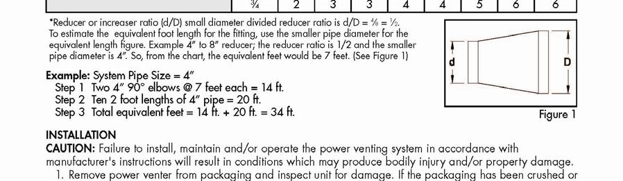
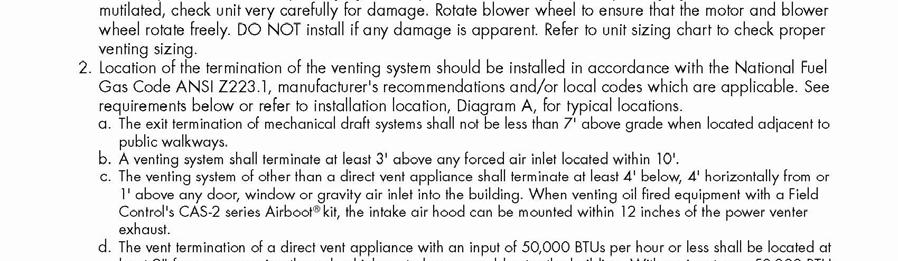
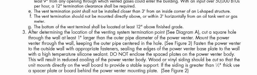
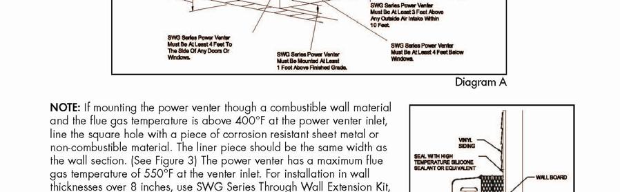
3 Installation Safety Instructions 1. Safety inspection of a venting system should be performed before and after installing a power venting system on an existing or new appliance. Follow NFPA 211, the International Mechanical Code and/or The International Residential Code for information on inspection requirements. WARNING: THIS DEVICE MUST BE INSTALLED BY A QUALIFIED INSTALLER IN ACCORDANCE WITH THE INSTRUCTIONS IN THIS MANUAL. A QUALIFIED AGENCY IS DEFINED AS: ANY INDIVIDUAL, FIRM, CORPORATION, OR COMPANY WHO EITHER IN PERSON OR THROUGH A REPRESENTATIVE IS IN ENGAGED IN, AND IS RESPONSIBLE FOR INSTALLATION AND OPERATION OF SOLID FUEL BURNING HEATING APPLIANCES. WHO IS EXPERIENCED IN SUCH WORK, FAMILIAR WITH ALL PRECAUTIONS REQUIRED, AND HAS COMPLETED THE REQUIREMENTS OF THE AUTHORITY HAVING JURISDICTION. 2. Plan the venting system layout before installation to avoid the possibility of accidental contact with concealed wiring or plumbing. 3. Single wall pipe may be used to join the stove with the power vent, check local and national codes for guidelines. 4. This equipment is designed to overcome minor negative pressure conditions in perform the steps in the General Installation Inspection section of this manual. 5. All Leisure Line stoves, boilers and furnaces which utilize a power vent must be fitted with a WMO-1 flue safety interlock switch per the instructions contained in this manual. 6. Piping clearances to combustables, length, fitting configuration and location of the venting system outlet should be installed in accordance with manufacturers recommendation as shown in the following excerpts from the Field Controls Manual: Page 3 of 23

4 Page 4 of 23

5 Page 5 of 23

6 Page 6 of 23

7 Page 7 of 23
8 Installation Instructions 1. This manual is designed to be used in conjunction with the Field Controls manual that comes with your power venter. NOTE: THE TYPE HDS POWER VENTERS HAVE BEEN TESTED WITH LEISURE LINE STOVES PER UL 1482 BY CONAM INSPECTIONS INC, AUBURN MA THE TYPE AF POWER VENTERS WERE TESTED WITH LEISURE LINE STOVES, FURNACES, AND BOILERS PER UL 1482, AND 1523 BY INTERTEK TESTING SERVICES OF MIDDLETON, WI ANY DEVIATION FROM THESE INSTRUCTIONS COULD RENDER THE POWER VENTER NON-COMPLIANT WITH UL SAFETY STANDARDS. 2. Open/Unpack Power Vent and barometric damper, check for damage. Rotate Venter wheel to ensure that the assembly rotates freely. CAUTION: DO NOT INSTALL POWER VENT IF ANY DAMAGE IS EVIDENT 3. Check for all parts for your particular Power Vent model per the table below. Power Vent Application WMO Safety Reducer Size Model Switch Wiring 4HDS All Stove models Plug in Cords 4 X 6 4AF All Stove Models Plug in Cords 4 X 6 5AF AnthraKing Furnace and WL 110 Boiler Flexible metal conduit, customer 5 X 6 5AF AnthraKing Furnace and 220 Boiler provided Flexible metal conduit, customer provided 5 X 8 3. Plan for the installation using the data contained in the previous section, ensure that the location of the power vent outlet is in compliance with all requirements. NOTE: ENSURE THAT THE POWER VENTER IS NOT INSTALLED WITH THE MOTOR SHAFT IN A VERTICAL POSITION. THIS WILL LEAD TO PREMATURE MOTOR FAILURE, ADDITIONALLY THE STOVE SHOULD BE LOCATED AS CLOSE AS POSSIBLE TO THE POWER VENTER. 4. Select a location for the power vent and cut the hole, install the power venter per instructions and clearances found in the Installation Safety Instructions and per local and national codes. It is recommended that if an inspection is required, a walk through with the inspector be performed prior to cutting the hole. 5. Secure the power venter and trim, secure the rheostat box to the wall and reconnect the rheostat wiring. Provide power to the unit and verify proper operation. Page 8 of 23
9 6. The venting system should be installed and supported win accordance with any local codes. A vent pipe connector shall b supported for the design and weight of the material employed, to maintain clearances, prevent physical damage and separation of joints. A reducer as shown in the above table should be attached directly to the power venter so that the larger pipe is runs the entire length from the appliance. 7. Minimize the number of elbows and tees per the inserted manufacturers data contained in the Installation Safety Instructions. 8. Secure all pipe joints with three sheet metal screws and use only 24 gauge or thicker black stove pipe for the connection to the appliance. 9. Mount the barometric draft control and install the weight on the appropriate scale for orientation. H scale is used for horizontal installation of the T and V is used for Vertical Installation of the T. Level the pivot shaft and verify free operation. Page 9 of 23

10 Page 10 of 23
11 Page 11 of 23

12 10. Install the WOMO-1 flue switch in the stove using a 3/4 hole saw. The switch should be installed slightly below the level of the grate and in the side or back of the stove four to six inches from the corner. Take care not to drill through a stiffener and to mount the switch above the level of the ash pan. Some stoves will not have enough room to mount the switch in the back. For furnace and boiler installation the flue switch should be installed in the flue outlet as close to the appliance as possible. The WMO-1 must disconnect power to the burn appliance when it trips, momentarily pushing the red button through the small hole in the cover will test this. 11. For stoves plug the flue switch into a wall outlet and plug the Coal-Trol power cord into the female plug provided on the WMO-1. For boiler and furnace installations the unit will be hard wired to a power source and in series with the power WARNING: FOR CONTINUED SAFE OPERATION, THE STOVE, BOILER, OR FURNACE VENT SYSTEM COMBINATION IS REQUIRED TO BE CLEANED, INSPECTED AND MAINTAINED ANNUALLY BY A QUALIFIED AGENCY Power Venter Concept of Operation and General Information 1. A Leisure Line power venter is designed to replace a chimney by providing a draft in the flue pipe. The unit must be used in combination with a barometric draft control and operates continuously as long as the appliance is burning. Speed is controlled by means of a rheostat so that the barometric draft control shows visible sign that there is draft during all burn levels (just slightly moving as a minimum). 2. A WMO-1 blocked flue switch is a required part of the installation and is hooked in series with power to the appliance to ensure shut down in the event of a loss of draft. 3. Ensure that the installation is adequate for safe operation by performing the General Installation Inspection after initial installation and after any major modification to the home. 4. Proper maintenance is important for trouble free and safe operation. Fly ash can build up and block the flue pipe, ensure that periodic inspections are performed by a qualified person. Remember that moisture under the hopper lid is a sign of poor draft and should never be ignored. 5. Fly ash is also corrosive, proper cleaning will ensure a long life and the safety of you and your family. Page 12 of 23
13 General Installation Inspection The following procedure will help evaluate the venting system and must be performed before placing the power vent into service. It is intended as a guide to aid in determining that the venting system is properly installed and is in a safe condition for continuous use. This procedure should be recognized as a generalized procedure which cannot anticipate all situations. Accordingly, in some cases deviation from this procedure may be necessary to determine safe operation of the equipment. 1. Visually inspect the venting system for proper size and determine that there is no flue gas spillage, blockage, restriction, leakage, corrosion or other deficiency which could cause unsafe operation. 2. Close all doors, windows, fire dampers and other openings in the area where the burn appliance is located. Turn on all clothes dryers, exhaust fans, range hoods and other vents at maximum speed. 3. Set the weight on the barometric draft control to align with the 3 or 4 on the proper scale (H for horizontal installation and V for vertical installation). 4. Ensure that the appliance lit and in max burn mode so that max output is held (adjust thermostat or whatever control is in play to achieve this), measure the draft to ensure that it is -.04 to -,06 WC at the flue outlet of the appliance. Adjust the rheostat knob so that the desired draft is present and the barometric damper door is just moving slightly at full burn. 5. Visually determine that the flame on the burn grate is blue and consistent. This is a sign that there is sufficient combustion air for proper operation of the unit. WARNING: THE NEXT STEP WILL POSSIBLY RELEASE CARBON MONOXIDE TO THE ROOM, ENSURE THAT THERE IS A WORKING CARBON MONOXIDE DETECTOR IN THE AREA BEFORE PERFORMING. 6. Momentarily shut off the power vent and ensure that the WMO-1 trips off within 10 minutes or so. Restart the power venter and reset the WMO After 30 minutes of operation test for spillage at the barometric draft control using a match or smoke from a candle or cigarette. If spillage occurs there is not enough combustion air, refer to National Flue Gas Code, A.N.S.I. Z223.1 or any applicable local codes for guidance. 8. After completion of the test return all doors, windows, dampers, and fans to there normal condition. In Season Maintenance 1. Check Elbows and horizontal pipe runs for fly ash build up every ton of coal used, clean as needed. 2. Clean flue pipe at exit of appliance every month or so. 3. Clean the screen opening on the exterior from any foreign objects monthly. 4. Perform the maintenance steps found in Appendix A every 4 to 6 weeks. 5. Oil fan motor every two months or so with 1 drop of Superlube or 0W5 synthetic oil. 6. Ensure that the inlet of the WMO-1 safety switch is free from fly ash by placing the vacuum hose over the inlet Page 13 of 23
14 Resolution of Common Problems 1. If the power vent speed is still too fast at the minimum rheostat setting, there is a tuning screw on the side of the rheostat that can reduce the speed. 2. The power vent will make a rumbling noise when dirty or in need of lubrication. Recommended Spare Parts 1. Generally speaking the power venter fan will last a lifetime with proper maintenance, the heat slinger (cooling fan for the motor may need replacement due to it s aluminum construction. Inspect this item each year and keep a replacement handy in the event it has deteriorated beyond serviceable condition. With proper cleaning and oiling the fan motor should last in excess of 5 years. End of Season Maintenance 1. Remove all flue pipes from the stove and power venter. Take pipes and ash pans outside and wash down thoroughly and dry in ths sun. 2. Inspect all vent connections for looseness, evidence of corrosion or leakage. Check the barometric draft control for free movement and re-level it when re-installed for the next burn season. 3. Remove the power venter fan and motor assembly and block the opening. 4. Coat all flue pipe and fan assembly with WD-40 or other suitable metal protector and store in a dry location. 5. Disconnect power to the appliance, remove the WMO-1 cover assembly. Remove the two screws holding the control box to the heat transfer assembly. The control box slides, unlocking it from the heat transfer tube assembly. Carefully remove any buildup from the thermal switch surface. CAUTION: DO NOT DENT OR SCRATCH THE SURFACE OF THE THERMAL SWITCH, IF THE THERMAL SWITCH IS DAMAGED REPLACE IT. 6. Clear and remove any buildup or obstruction inside the heat transfer tube. Remount, lock and refasten the control box with the two screws. Reattach the assembly cover, and connect power to the appliance. Page 14 of 23

15 APPENDIX A SWG 4HDS Power Vent Maintenance Instructions Page 15 of 23

16 Appendix B SWG 4RMK Motor Replacement Kit Instructions Page 16 of 23

17 Page 17 of 23
18 Page 18 of 23
19 Page 19 of 23
20 Appendix C SWG Superlube Information Page 20 of 23
21 Appendix D SWG Type AF Installation Information Page 21 of 23
22 Page 22 of 23
23 Appendix E SWG Type AF Wiring Information Page 23 of 23
Leisure Line Power Vent Operations & Maintenance Manual And Safety Instructions
 Leisure Line Power Vent Operations & Maintenance Manual And Safety Instructions Black Rock Manufacturing DBA Leisure Line Stove Company Rear 620 Broad Street Berwick, PA 18603 http://www.leisurelinestoves.com/ind
POWER VENTER. Model: PVE Series
 POWER VENTER Model: PVE Series CONTENTS Typical Venting System Components... System Operation... Power Venter Sizing... Installation Safety Instructions... Installation of Power Venter... Connecting Power
POWER VENTER SYSTEM. Model: PVO-300, PVO-600
 POWER VENTER SYSTEM Model: PVO-300, PVO-600 Included is one ETL and cetl listed Power Venter to be used primarily with a single 120VAC controlled oil fired furnace, boiler, or water heater. The PVO may
PVE SERIES POWER VENTER SYSTEM MANUAL
 PVE SERIES POWER VENTER SYSTEM MANUAL Contents Page I. Typical Venting System Components 2 II. System Operation 3 III. Power Venter Sizing 3,4 IV. Installation Safety Instructions 5,6 V. Installation of
EUTECTIC EC-10DV Series
 EUTECTIC EC-10DV Series DIRECT VENT OIL-FIRED WATER BOILER/NO. 2 OIL VENTING INSTALLATION INSTRUCTIONS CONTENTS..........................................PAGE Basic Guidelines..........................................1
120 VAC SYSTEM CONTROL KIT
 120 VAC SYSTEM CONTROL KIT Designed for use on SWG Series Power Vent Hoods for controlling oil fired heating appliances with 120 VAC controls. Model: CK-63 The CK-63 control has the ability to operate
POWER VENTER SYSTEM MODEL: PVO-300, PVO-600
 POWER VENTER SYSTEM MODEL: PVO-300, PVO-600 Included is one ETL and cetl listed Power Venter to be used primarily with a single 120VAC controlled oil fired furnace, boiler, or water heater. The PVO may
COMBUSTION AIR SYSTEM
 COMBUSTION AIR SYSTEM MODEL: CAS-4JR This product is designed for use with any natural gas or LP burning furnace, water heater, or boiler with a 24 VAC control system. It may be used with a residential
24 VAC SYSTEM CONTROL KIT
 24 VAC SYSTEM CONTROL KIT Model: CK-43 Tubing MG1 Barometric Draft Control The CK-43 is designed for use with the SWG Series Power Venter for controlling Natural Gas and L.P. Gas Draft Induced appliances.
SYSTEM CONTROL KIT. Model: CK-62. Designed for use on SWG Series Power Vent Hoods for controlling oil fired heating appliances with 120 VAC controls.
 SYSTEM CONTROL KIT Model: CK-62 Designed for use on SWG Series Power Vent Hoods for controlling oil fired heating appliances with 120 VAC controls. ITEMS INCLUDED IN KIT: 1) Junction box with mounted pressure
Leisure Line Stoves are to be used as supplemental heat only. Do not use this stove as a replacement for a furnace.
 Leisure Line Stoves are to be used as supplemental heat only. Do not use this stove as a replacement for a furnace. NOTES: Actuation of your CO alarm indicates the presence of CO. Turn off your coal stove
POWER VENTER SYSTEM. Model: PVG-100, PVG-300, PVG-600
 POWER VENTER SYSTEM Model: PVG-100, PVG-300, PVG-600 Included is one ETL LISTED power venter to be used for side wall venting of a single 24 VAC controlled furnace, boiler, or water heater which burns
SIDEWALL POWER VENTING KIT
 SIDEWALL POWER VENTING KIT Model: SWG-4G GENERAL SYSTEM INFORMATION Designed for operation with natural gas and LP gas. 1. The thermostat calls for heat and energizes a relay which activates the power
SIDEWALL POWER VENTER KIT
 SIDEWALL POWER VENTER KIT Model: CV- 4VR, -5VR Vent Riser Models CK series control kit sold separately *Patented TYPICAL VENTING SYSTEM COMPONENTS 1 CV-VR Series Power Venter 1 - CK Series Control Kit
120 VAC SYSTEM CONTROL KIT Model: CK-63
 120 VAC SYSTEM CONTROL KIT Model: CK-63 Designed for use on SWG Series Power Vent Hoods for controlling oil fired heating appliances with 120 VAC controls. The CK-63 control has the ability to operate
SIDEWALL POWER VENTER KIT
 SIDEWALL POWER VENTER KIT Model: SWG, SWGII & SWG Stainless Series *Patented TYPICAL VENTING SYSTEM COMPONENTS 1 - SWG Series Power Venter 1 - CK Series Control Kit (sold separately) OPTIONAL SYSTEM COMPONENTS
120 VAC SYSTEM CONTROL KIT
 120 VAC SYSTEM CONTROL KIT Model: CK-61 Designed for use on SWG Series Power Vent Hoods for controlling oil fired heating appliances with 120 VAC controls. ITEMS INCLUDED IN KIT: 1- Junction box with mounted
READ THESE INSTRUCTIONS CAREFULLY AND COMPLETELY BEFORE PROCEEDING WITH THE INSTALLATION.
 Combustion Air system MODEL: CAS-4JR This product is designed for use with any natural gas or LP burning furnace, water heater, or boiler with a 24 VAC control system. It may be used with a residential
24 VAC SYSTEM CONTROL KIT Model: CK-91F and CK-91FG
 24 VAC SYSTEM CONTROL KIT Model: CK-91F and CK-91FG Designed for use with the SWG Series Power Venter for controlling Natural Gas or L.P. Gas draft induced appliances with a 24 VAC Gas Valve and a 30-millivolt
INSTALLATION INSTRUCTIONS
 INSTALLATION INSTRUCTIONS NAHA001DH & NAHA002DH Chimney Adapter Kit Category I Furnace Vent Accessory KEEP THESE INSTRUCTIONS WITH THE FURNACE SAFETY REQUIREMENTS Improper installation, adjustment, alteration,
Vent Supplement Ultra-80, -105, -155, -230 & -310
 Gas-fired water boiler Vent Supplement Ultra-80, -105, -155, -230 & -310 Installation of: Vent piping Air piping with This document must only be used by a qualified heating installer/service technician.
(Information about THERMAL dampers for gas-fired appliances available on request.) WARNING
 WARNING") FLAIR INTERNATIONAL CORPORATION 600 OLD WILLETS PATH HAUPPAUGE, NEW YORK 11788 U.S.A. TEL.: (516) 234-3600 FAX: (516) 234-3610 SPECIFICATIONS, INSTALLATION INSTRUCTIONS AND TROUBLE-SHOOTING GUIDE FOR STACK
FLAIR INTERNATIONAL CORPORATION 600 OLD WILLETS PATH HAUPPAUGE, NEW YORK 11788 U.S.A. TEL.: (516) 234-3600 FAX: (516) 234-3610 SPECIFICATIONS, INSTALLATION INSTRUCTIONS AND TROUBLE-SHOOTING GUIDE FOR STACK
24 VAC SYSTEM CONTROL KIT
 24 VAC SYSTEM CONTROL KIT Model: CK-91F and CK-91FG Designed for use with the SWG Series Power Venter for controlling Natural Gas or L.P. Gas draft induced appliances with a 24 VAC Gas Valve and a 30-millivolt
INSTALLER'S GUIDE MASONRY CHIMNEY VENT KIT WARNING: BAYVENT800B 18- CH23D2-05
 INSTALLER'S GUIDE IMPORTANT This Document is customer property and is to remain with this unit. Please return to service information pack upon completion of work. Model: BAYVENT800B For use with Category
VENTING CLEARANCES. BBT NORTH AMERICA Bosch Group. Bosch Water Heating 340 Mad River Park, Waitsfield, VT TWH-V-26 page 1 of 6 rev 01/06
 page 1 of 6 VENTING CLEARANCES The vents should not be obstructed and all joints properly fitted. Floors, ceilings and walls must be cut or framed to provide necessary clearance to vents. Metal strippings
Hitzer Energy Master II Stoker Furnace Model 710 Owner s Manual Installation and Operation
 Hitzer Energy Master II Stoker Furnace Model 710 Owner s Manual Installation and Operation Save this Manual Operating Instructions and Maintenance Enclosed. Thoroughly Read and Understand Instructions.
MODEL HS115-3, HS115-4 & HS115-5 WIRING DIAGRAM ADDENDUM
 TJERNLUND PRODUCTS, INC. 1601 Ninth Street White Bear Lake, MN 55110-6794 PHONE (800) 255-4208 (651) 426-2993 FAX (651) 426-9547 Visit our web site www.tjernlund.com MODEL HS115-3, HS115-4 & HS115-5 WIRING
Direct Vent System Required
 CB-200A Cottage Base Installation Instructions IMPORTANT: Read all instructions carefully before beginning the installation. This base must be installed by a qualified installing agency and in accordance
COMBUSTION AIR SYSTEM Model: CAS-3
 COMBUSTION AIR SYSTEM Model: CAS-3 This product is designed for use with any oil burning furnace, water heater, or boiler with 120 VAC control systems. It may also be used with more than one appliance.
Owner s Manual for. PennStoker
 Owner s Manual for PennStoker Table of Contents 1. Installation Placement ---------------------------------------------------------------------------------------- pg.3 Chimney Hook-up ---------------------------------------------------------------------------
Indiana WX Oil Furnace Inspection Guide
 Indiana WX Oil Furnace Inspection Guide Client: Job # : Address: Phone: Client Interview: Oil Dealer: Date of last service: Comments/Billing information: Standard Inspection / Clean and Tune Follow-up:
CHIMNEY INSTALLATION. Technical Bulletin #1
 Technical Bulletin #1 CHIMNEY INSTALLATION A chimney performs two functions: it removes smoke and flue gases from the stove/furnace, and it provides draft for the fire. Draft is the term used to describe
INSTALLATION AND SERVICE MANUAL
 INSTALLATION AND SERVICE MANUAL VERTICAL COMBUSTION AIR INLET KITS CATEGORY III VENTING FOR SEPARATED COMBUSTION TUBULAR GAS FIRED UNIT HEATERS USE 5 INCH KIT FOR UNITS WITH CAPACITIES 100,000 TO 250,000
INSTALLATION AND SERVICE MANUAL
 INSTALLATION AND SERVICE MANUAL HORIZONTAL COMBUSTION AIR INLET KITS CATEGORY III VENTING FOR SEPARATED COMBUSTION TUBULAR GAS FIRED UNIT HEATERS USE 5 INCH KIT FOR UNITS WITH CAPACITIES 100,000 TO 250,000
ELECTRONIC FIREPLACE DAMPER
 ELECTRONIC FIREPLACE DAMPER Model: FSE Series The Flue Sentinel Electronic Fireplace Damper is designed to increase the comfort and energy efficiency of residential homes with gas-fired fireplaces. Consisting
24 VAC SYSTEM CONTROL KIT
 24 VAC SYSTEM CONTROL KIT Model: CK-92F and CK-92FG Designed for use with the SWG Series Power Venter for controlling Natural Gas or L.P. Gas appliances with a 24 VAC Gas Valve and a 30-millivolt controlled
WARNING FLAIR INTERNATIONAL CORPORATION 600 OLD WILLETS PATH HAUPPAUGE, NEW YORK U.S.A. TEL.: (516) FAX: (516) AMERICAN
 FAX: (516) AMERICAN") 600 OLD WILLETS PATH HAUPPAUGE, NEW YORK 11788 U.S.A. TEL.: (516) 234-3600 FAX: (516) 234-3610 SPECIFICATIONS, INSTALLATION INSTRUCTIONS AND TROUBLE-SHOOTING GUIDE FOR STACK PACK MOTORIZED VENT DAMPER
600 OLD WILLETS PATH HAUPPAUGE, NEW YORK 11788 U.S.A. TEL.: (516) 234-3600 FAX: (516) 234-3610 SPECIFICATIONS, INSTALLATION INSTRUCTIONS AND TROUBLE-SHOOTING GUIDE FOR STACK PACK MOTORIZED VENT DAMPER
ELECTRONIC FIREPLACE DAMPER
 ELECTRONIC FIREPLACE DAMPER Model: FSE Low Profile Series The Flue Sentinel Electronic Fireplace Damper is designed to increase the comfort and energy efficiency of residential homes with gas-fired fireplaces.
ASX7-5-IOM-3 J
 INSTALLATION INSTRUCTIONS 5" CONCENTRIC VENT TERMINAL KIT TUBULAR GAS FIRED DIRECT SPARK PROPELLER UNIT HEATERS UNIT CONVERSION & CATEGORY III VENTING FOR SEPARATED COMBUSTION For 90,000 to 120,000 BTU/HR
Draft and Venting. Chapter 6
 Chapter 6 Introduction Air is needed to burn oil cleanly and efficiently. We must understand how to supply air to the burner and how to ensure that all of the gases created in burning the fuel are vented
COMBUSTION AIR SYSTEM
 COMBUSTION AIR SYSTEM MODEL: CAS-2WM WEIL-MCLAIN OUTSIDE AIR KIT FOR USE WITH OIL BURNER MODELS QB-180 & QB-300 4" VRV 4" IAH HOOD AIR BOOT TM The Air Boot model CAS-2WM is for use only on the designated
ASX7-4-IOM-6 J
 INSTALLATION INSTRUCTIONS 4" COMBUSTION AIR INLET KIT TUBULAR GAS FIRED DIRECT SPARK PROPELLER UNIT HEATERS UNIT CONVERSION & CATEGORY III VENTING FOR SEPARATED COMBUSTION For 30,000 to 75,000 BTU/HR SUPPLEMENT
K-2 & K-6 Direct Vent
 K-2 & K-6 Direct Vent Operating instructions and maintenance enclosed Thoroughly read and understand instructions Always leave this manual with stove owner Follow the instructions within this manual. If
Do not use this vent pipe or fittings for venting incinerators of any kind.
 ! CAUTION! Do not use this vent pipe or fittings for venting incinerators of any kind. C.S.A. Certified For Natural Gas Or Propane Tested For 100 LBS. ASME Working Pressure For correct installation of
INSTALLATION INSTRUCTIONS & USE & CARE GUIDE Air-O Ultra Series Range Hoods
 INSTALLATION INSTRUCTIONS & USE & CARE GUIDE Air-O Ultra Series Range Hoods Ultra Series Models: UL2824 UL2830 UL2836 CONTENTS: Part 1 - Planning The Installation Part 2 - Electrical Connection Part 3
INTRODUCTION TO HITZER STOVES INSTALLATION AND OPERATION
 INTRODUCTION TO HITZER STOVES INSTALLATION AND OPERATION Welcome to our proud team of HITZER heater owners. Your HITZER heater has the finest in Swiss craftsmanship and quality material to assure you that
Installation, Operation and Maintenance Manual. 90,000 BTU & 105,000 BTU Stoker Coal Stoves
 Installation, Operation and Maintenance Manual 90,000 BTU & 105,000 BTU Stoker Coal Stoves 105K BTU Stove Shown About Us Keystoker had its inception in 1946. Two electrical engineers saw the need for a
Installation Instructions
 Single-Stage Tables For Category I Fan-Assisted Furnaces Installation Instructions NOTE: Read the entire instruction manual before starting the installation. SAFETY CONSIDERATIONS Installing and servicing
OWNER S GUIDE COMMERCIAL POWER VENTER KITS USED IN CONJUNCTION WITH FLUE DAMPERED COMMERCIAL WATER HEATERS TABLE OF CONTENTS
 OWNER S GUIDE COMMERCIAL POWER VENTER KITS USED IN CONJUNCTION WITH FLUE DAMPERED COMMERCIAL WATER HEATERS TABLE OF CONTENTS Kit Components Table Page 1 Damper Adjustment Page 6 Vent Terminal Dimensions
SYSTEM CONTROL KIT READ THESE INSTRUCTIONS CAREFULLY AND COMPLETELY BEFORE PROCEEDING WITH THE INSTALLATION.
 SYSTEM CONTROL KIT Model: CK-20F and CK-20FG (NOTE: CK-20FG units are designed for the Flame Guard units built by American Water Heater. All other manufacturers use CK-20F) Designed for use with the SWG
Installation, Operation and Maintenance Manual. 90,000 BTU & 105,000 BTU Stoker Coal Stoves, Direct Vent
 Installation, Operation and Maintenance Manual 90,000 BTU & 105,000 BTU Stoker Coal Stoves, Direct Vent 105K BTU Stove Shown December 2016 REV 1 About Us Keystoker had its inception in 1946. Two electrical
Installation, Operation and Maintenance Manual. Koker, Koker Lite & Econo 90 Stoker Coal Stoves
 Installation, Operation and Maintenance Manual Koker, Koker Lite & Econo 90 Stoker Coal Stoves Koker Stove Shown About Us Keystoker had its inception in 1946. Two electrical engineers saw the need for
Second Revision No. 3 implements the text of Committee Input No. 36 as proposed in the First Draft Report, along with the following amendments:
 Second Revision No. 3-NFPA 31-2015 [ Section No. 10.5.1 ] 10.5.1* Oil burners, other than oil stoves with integral tanks, shall be provided with some means for manually stopping the flow of oil to the
Installation & Maintenance Instructions
 Installation & Maintenance Instructions Listed & Tested to UL641, ULC-S609, ULC/ORD C441 AMERIVENT Model PVP Pellet Pipe Plus Vent Connector for Pellet-Fuel Appliances and Other Low-Temperature Applications
OWNERS MANUAL MODEL DO110 & DO180 IS CERTIFIED TO: Unit Serial # Purchased From Company Address
 OWNERS MANUAL MODEL DO110 & DO180 IS CERTIFIED TO: UL 391 CAN/CSA B366.1 Unit Serial # Purchased From Company Address Name of Installer Installer Telephone # Date Installed IMPORTANT This manual must be
RS Chimney Fan for Solid Fuel Applications
 Installation & Operating Manual RS Chimney Fan for Solid Fuel Applications USA CAN Product Information... Chapter 1 + 2 Mechanical Installation... Chapter 3 Electrical Installation... Chapter 4 Start Up
USER'S INFORMATION MANUAL
 USER'S INFORMATION MANUAL SERIES DV GAS FIRED HOT WATER HEATING BOILER WARNING: If the information in this manual is not followed exactly, a fire or explosion may result causing property damage, personal
GENERAL BASIC INSTALLATION INSTRUCTIONS DIRECT FIRED HOT WATER BOILERS PARKER BOILER CO.
 GENERAL BASIC INSTALLATION INSTRUCTIONS DIRECT FIRED HOT WATER BOILERS PARKER BOILER CO. GBI 201-5 3C For a proper installation and in order to receive the best in operating life and efficiency from your
USER'S INFORMATION MANUAL
 USER'S INFORMATION MANUAL SERIES ODVB GAS FIRED HOT WATER HEATING BOILER WARNING: If the information in this manual is not followed exactly, a fire or explosion may result causing property damage, personal
Objectives. Home Performance Diagnostics with the House of Pressure (Part 1) How can Pressure effect Building Performance?
 How can Pressure effect Building Performance?") Home Performance Diagnostics with the House of Pressure (Part 1) Objectives Learn the basic rules of air flow and differences Begin to be able to recognize building problems related to airflow and differences
Home Performance Diagnostics with the House of Pressure (Part 1) Objectives Learn the basic rules of air flow and differences Begin to be able to recognize building problems related to airflow and differences
RSIF power venter USA CAN READ AND SAVE THESE INSTRUCTIONS! Installation and operation manual. Product information Chapters 1 + 2
 3002239 RSIF 2014-04-04 Installation and operation manual RSIF power venter READ AND SAVE THESE INSTRUCTIONS! Product information Chapters 1 + 2 Mechanical installation Chapter 3 Electrical installation
RSIF Power Venter USA CAN. Product Information. ... Chapters Mechanical Installation. ... Chapter 3. Electrical Installation. ...
 Installation & Operating Manual RSIF Power Venter USA CAN Product Information... Chapters 1 + 2 Mechanical Installation... Chapter 3 Electrical Installation... Chapter 4 Start Up and Configuration... Chapter
SERVICE FACTS WARNING M801-SF-1C. Gas Furnaces Upflow & Downflow Induced Draft 1 Stage Heat Models: DISCONNECT POWER BEFORE SERVICING M801P040AU24AA
 SERVICE FACTS Gas Furnaces Upflow & Downflow Induced Draft Stage Heat Models: M80P00AU2AA M80P060AU2AA M80P060AU36AA M80P080BU36AA M80P080BU8AA M80P00BU36AA M80P00CU8AA M80P00CU60AA M80PDU60AA M80P0DU60AA
about your house Assessing the Comfort and Safety of Your Home s Mechanical Systems
 about your house CE 28 k Assessing the Comfort and Safety of Your Home s Mechanical Systems The heating, ventilating and air conditioning (HVAC) systems are a vital part of every home. These mechanical
GPC PASTA PRO INSTALLATION & USER OPERATION MANUAL
 GPC-14/18/20 GPC PASTA PRO INSTALLATION & USER OPERATION MANUAL GPC-18 shown with optional rinse station. NOTICE! After installation of your equipment, immediately contact your local gas supplier to obtain
Leisure Line WL110 Boiler Operations & Maintenance Manual And Safety Instructions
 Thank you for Purchasing a Leisure Line Coal Stoker Boiler. Proper Care and Maintenance are an important part of getting the CAUTION Burn Rice or Buckwheat Sized Anthracite Coal only in the WL110 Boiler.
DR-180 Through the Wall Exhaust Fan PRODUCT MANUAL & INSTALLATION GUIDE
 DR-180 Through the Exhaust Fan PRODUCT MANUAL & INSTALLATION GUIDE READ AND SAVE THESE INSTRUCTIONS READ CAREFULLY BEFORE ATTEMPTING TO ASSEMBLE, INSTALL, OPERATE OR MAINTAIN THE PRODUCT DESCRIBED. PROTECT
WARNING FIRE OR EXPLOSION HAZARD.
 2017 Lennox Industries Inc. Dallas, Texas, USA 506897-01 04/2017 Supersedes 10/2015 EL280DF SERIES GAS FURNACE Improper installation, adjustment, alteration, service or maintenance can cause property damage,
Leisure Line AA220 Boiler Operations & Maintenance Manual And Safety Instructions
 Leisure Line AA220 Boiler Operations & Maintenance Manual And Safety Instructions SAFETY NOTICE PLEASE READ ENTIRE MANUAL BEFORE INSTALLING YOUR NEW BOILER. FAILURE TO FOLLOW THESE INSTRUCTIONS MAY RESULT
COMBUSTION APPLIANCE SAFETY INSPECTION FOR VENTED APPLIANCES*
 COMBUSTION APPLIANCE SAFETY INSPECTION FOR VENTED APPLIANCES* *Vented appliances refer to natural draft appliances equipped with a barometric draft regulator or Category I appliances equipped with a draft
SYSTEM CONTROL KIT Model: CK-41P
 SYSTEM CONTROL KIT Model: CK-41P READ THE INSTALLATION INSTRUCTIONS CAREFULLY & COMPLETELY BEFORE BEGINNING THE INSTALLATION! Designed for use with the SWG Series Power Venter for controlling Natural Gas
GENERAL BASIC INSTALLATION INSTRUCTIONS INDIRECT GAS FIRED WATER HEATERS PARKER BOILER CO.
 GENERAL BASIC INSTALLATION INSTRUCTIONS INDIRECT GAS FIRED WATER HEATERS PARKER BOILER CO. GBI 210 3C For a proper installation and in order to receive the best in operating life and efficiency from your
Ventis Direct Vent. Installation Instructions
 entis Direct ent Installation Instructions A MAJOR CAUSE OF CHIMNEY RELATED FIRES IS FAILURE TO MAINTAIN REQUIRED CLEARANCES (AIR SPACES), TO COMBUSTIBLE MATERIALS. IT IS OF THE UTMOST IMPRORTANCE THAT
X341119P10 Gas Furnace Var. Speed Blower Var. Speed Inducer Two Stage Heat Direct Vent Models:
 Service Facts X349P0 Gas Furnace Var. Speed Blower Var. Speed Inducer Two Stage Heat Direct Vent Models: *UY060R9V3W *UY080R9V3W *UY00R9V4W *UY20R9V5W * First letter may be A or T *DY060R9V3W *DY080R9V3W
USER S INFORMATION MANUAL
 USER S INFORMATION MANUAL UPFLOW/HORIZONTAL & DOWNFLOW TWO STAGE INDUCED DRAFT GAS FURNACES Recognize this symbol as an indication of Important Safety Information If the information in this manual is not
K-2 & K-6 with 6 Inch Stack
 K-2 & K-6 with 6 Inch Stack Operating instructions and maintenance enclosed Thoroughly read and understand instructions Always leave this manual with stove owner Follow the instructions within this manual.
INDUCED DRAFT HIGHBOY AND COUNTERFLOW/HORIZONTAL GAS FURNACE
 INDUCED DRAFT HIGHBOY AND COUNTERFLOW/HORIZONTAL GAS FURNACE USERS INFORMATION MANUAL MODELS FOR USE WITH NATURAL GAS MHA-50N, MHA-75N, MHA-100N, MHA-125N, MDA-50N, MDA-75N, MDA-100N, MDA-125N FOR USE
BESB Box Ventilator USA CAN. Product Information. Mechanical Installation. ... Chapter 3. Electrical Installation. ... Chapter 4
 Installation & Operating Manual BESB Box Ventilator USA CAN Product Information... Chapter 1 + 2 Mechanical Installation... Chapter 3 Electrical Installation... Chapter 4 Start Up and Configuration...
Crown Boiler Company
 Crown Boiler Company Oil Vent Damper Supplemental Installation Instructions Converts Select TWZ Series Boilers to High Efficiency TWD Series Boilers These supplemental installation instructions are to
RS Chimney Fan for Solid Fuel Applications
 Installation & Operating Manual RS Chimney Fan for Solid Fuel Applications USA CAN Product Information... Chapters 1 + 2 Mechanical Installation... Chapter 3 Electrical Installation... Chapter 4 Start
2012 INTERNATIONAL FUEL GAS CODE VENTS
 2012 INTERNATIONAL FUEL GAS CODE SECTION 502 (IFGC) VENTS 502.1 General. All vents, except as provided in Section 503.7, shall be listed and labeled. Type B and BW vents shall be tested in accordance with
Installation Instructions Remote Blowers
 Installation Instructions Remote Blowers Models: REMP3, REMP16 Suitable for use in a household cooking area. Suitable for use with solid state controls. To complete this blower, a Dacor hood assembly or
OWNERS MANUAL LIBERATOR ROCKET HEATER Model: RMH-1
 OWNERS MANUAL LIBERATOR ROCKET HEATER Model: RMH-1 SAVE THIS MANUAL FOR FUTURE REFERENCE LIBERATOR STOVE, LLC ST. LOUIS, MO. (314)-770-1043 Thank you for your purchase of the Liberator Rocket Heater. This
Cookshack, Inc. Model FEC100 Fast Eddy Oven. Version /1/10
 Cookshack, Inc. Model FEC100 Fast Eddy Oven Operator s Manual Please read this entire manual installation and use of this pellet fired smoker oven. Failure to follow these instructions could result in
USER S INFORMATION MANUAL
 USER S INFORMATION MANUAL UPFLOW & DOWNFLOW/HORIZONTAL CONDENSING GAS FURNACES SAFETY Recognize this symbol as an indication of Important Safety Information If not installed, operated and maintained in
CMHC HOME MAINTENANCE CHECKLIST
 Make sure air vents indoors and outdoors (intake, exhaust and forced air) are not blocked by snow or debris. Check and clean range hood filters on a monthly basis. Test ground fault circuit interrupter(s)
INSTALLATION AND OPERATING INSTRUCTIONS TABLE OF CONTENTS IMPORTANT
 C US This manual must be left with owner and should be hung on or adjacent to the boilerfor reference. COMMON VENTING MODELS CHS-300 through CHS-399 INSTALLATION AND OPERATING INSTRUCTIONS TABLE OF CONTENTS
TABLE OF CONTENTS. Site preparation 2 Placement. 2 Chimney and stove pipe connections. 2
 TABLE OF CONTENTS SECTION TITLE PAGE 1. SITE PREPARATION AND INSTALLATION Site preparation 2 Placement. 2 Chimney and stove pipe connections. 2 Installation. 3 Water supply and return.. 3 Pressure/relief
INSTALLATION INSTRUCTIONS
 INSTALLATION INSTRUCTIONS HORIZONTAL COMBUSTION AIR INLET KITS CATEGORY III VENTING FOR SEPARATED COMBUSTION TUBULAR GAS FIRED DUCT FURNACES USE 5 KIT FOR UNITS WITH CAPACITIES 100,000 TO 200,000 BTU/HR
MODELS LFP4218/LFP6018 TOP VENT GAS FIREPLACE
 MODELS LFP4218/LFP6018 TOP VENT GAS FIREPLACE PFS APPROVED FOR NATURAL GAS OR PROPANE GAS Z21.50-2014 If your plans do not allow for the venting system as outlined previously in the installing chimney/vent
Section 42. Lead Paint Risk Factor NONE WATER HEATER STORAGE GAS
 WATER HEATER STORAGE GAS Lead Paint Risk Factor NONE TABLE OF CONTENTS PART 1: INSTALLATION REQUIREMENTS FOR CONVENTIONAL HOMES... 1 WATER HEATER REPAIR... 1 1. APPLIANCE REPAIR... 1 WATER HEATER INSTALLATION...
SIDEWALL VENTER Models :
 SIDEWALL VENTER Models : SMH-1-DE SMH-3-DE SMH-4-DE SMH-5-DE SMH-6-DE SMH-1-BR SMH-4-BR Caution: Do not tamper with the unit or its controls. Call a qualified service technician. Save these instructions
Water Distiller Service Manual
 Water Distiller Service Manual Water Distiller Service Manual L70478WT 2008 Regal Ware, Inc. Table of Contents RECOMMENDED TOOLS... 2 GENERAL INSPECTION...3 BOILING CHAMBER TROUBLESHOOTING & REPAIRS Description...
USER S, MAINTENANCE and SERVICE INFORMATION MANUAL
 CONTENTS SAFETY INFORMATION................ 2 FOR YOUR SAFETY....................... 2 SYSTEM OPERATION.................. 2 THERMOSTATS.......................... 2 INTERMITTENT IGNITION DEVICE...........
Corr/Guard PRESSURE RATED VENTING SYSTEM IMPORTANT: DO NOT INSTALL WITHOUT FIRST READING THESE INSTRUCTIONS VERY CAREFULLY.
 CORR/GUARD INSTALLATION INSTRUCTIONS This symbol on the nameplate means this product is listed by Underwriters Laboratories Inc. Tested to UL1738 / CAN / ULCS636-1995 Listing No. MH26687 Testing No. 11EN
CHAPTER 8 CHIMNEYS AND VENTS
 CHAPTER 8 CHIMNEYS AND VENTS SECTION 801 GENERAL 801.1 Scope. This chapter shall govern the installation, maintenance, repair and approval of factory-built chimneys, chimney liners, vents and connectors.
WOOD STOVE SERVICE MANUAL
 WOOD STOVE SERVICE MANUAL WARNING Fire Risk. Hearth & Home Technologies disclaims any responsibility for, and the warranty will be voided by, the following actions: Installation and use of any damaged
TYPE L VENT / VENT SYSTEM FOR PELLET BURNING APPLIANCES
 INSTALLATION INSTRUCTIONS & MAINTENANCE GUIDE TYPE L VENT / VENT SYSTEM FOR PELLET BURNING APPLIANCES LISTED TO ULC-S609 & UL641 A MAJOR CAUSE OF VENT RELATED FIRES IS FAILURE TO MAINTAIN REQUIRED CLEARANCES
MBPA Home Performance FIELD DATA COLLECTION FORM
 MBPA Home Performance FIELD DATA COLLECTION FORM Customer Information Test Date: Name Address City State Zip Phone: ( ) Email: Electric Provider Heating Fuel Provider Account Number Account Number Customer
OPERATION, MAINTENANCE AND PARTS MANUAL
 OPERATION, MAINTENANCE AND PARTS MANUAL MODEL LP - 200 - - SERIAL NUMBER ( ) 2014 March 28 2010 1 STICKERS YOU WILL FIND ON YOUR OVEN: DANGER-WARNING Never put your hands inside the oven while the stone