Suprima 30L - 100L. Installation & Service Instructions. About the Boiler
|
|
|
- Catherine Cunningham
- 5 years ago
- Views:
Transcription
1 Installation & Service Instructions Suprima 30L - 100L About the Boiler See inside cover for models covered by these instructions. This is a Wall Mounted Fan Assisted Balanced Flue Gas Boiler. This boiler is for use with Natural Gas (G20) only at 20mbar and for use in GB & IE. About Safety The Gas Safety (Installation and Use) Regulations In your own interest, and that of safety, it is law that all gas appliances are installed by competent persons, in accordance with the above regulations. Failure to install appliances correctly could lead to prosecution. Installation must be in accordance with the Installation & Service Instructions and the rules in force. Leave these instructions and the Benchmark Log Book with the user for use on future calls. SUP0003A TM The code of practice for the installation, commissioning & servicing of central heating systems
2 Contents Technical Data...3 Introduction Installation Requirements Health & Safety Information Codes of Practice Gas Supply Electricity Supply Location of Boiler Air Supply Flue Systems Flue Terminal Location The System Installation Unpack & Prepare the Boiler Install the Flue Connect the Power Supply Cable Install the Optional Programmer Connect the Gas Supply Connect the Water Supply Commissioning Commission the Boiler Final Adjustments Advise the User To Service the Boiler & Component Replacement General Access To Service the Boiler Component Replacement Electronic Control Board Air Pressure Switch Electrode Burner Injector Combustion Chamber Insulation Gas Valve Burner Combustion Chamber Insulation Gas Valve Injector s Fan & Flue Hood Temperature Sensor Overheat Thermostat Heat Exchanger Functional Wiring Diagram Wiring Diagrams Fault Finding Short List of Spares...36 The models covered by these instructions are:- Suprima 30L - G.C. No Suprima 40L - G.C. No Suprima 50L - G.C. No Suprima 60L - G.C. No Suprima 70L - G.C. No Suprima 80L - G.C. No Suprima 100L - G.C. No Potterton is a member of the Benchmark initiative and fully supports the aims of the programme. Benchmark has been introduced to improve the standards of installation and commissioning of central heating systems in the UK and to encourage the regular servicing of all central heating systems to ensure safety and efficiency. Important Failure to install and commission this appliance to manufacturer s instructions may invalidate the warranty. This note does not affect your statutory rights. The boiler model and serial number are given on the boiler data label which is located on the right hand side of the chassis and visible after opening the controls door. POTTERTON 9016 SUPRIMA 30 L G.C. No BOILER CODE No. ALVG SUP263A Flue Kits...38 System and Other Kits Contents Publication No
3 Technical Data Nominal Boiler Ratings Boiler models 30 kw 8.8 Output Btu/h kw 11.0 Input Burner setting pressure Gas Rate Btu/h mbar 9.3 in wg 3.70 m³/h 1.05 ft³/h 37.1 Injector Size mm dia Maximum Working Head Minimum Working Head Gas Supply Pressure Gas Supply Connection 30.5 m (100 ft) 150 mm (6 in) 20 mbar Rc. ½ (½ in BSP Female) (30-80 models) 15 mm copper tail (100 model) Maximum Flow Temperature 82 C Flow/Return Connections 22 mm Copper Water Content 1.7 litres (0.37 gal) - 30, 40 & 50 Models 2.1 litres (0.46 gal) - 60, 70, 80 & 100 Models SEDBUK Declaration for Suprima Model Seasonal Efficiency (SEDBUK) (%) 30L L L L L L L 78.0 Appliance Lift Weight Appliance Weight Installed - Dry 26.0 kg (57.3 lbs) - 30, 40 & 50 Models 30.2 kg (66.6 lbs) - 60, 70 & 80 Models 34.6 kg (76.3 lbs) Model 32.0 kg (70.0 lbs) - 30, 40 & 50 Models 35.4 kg (78.1 lbs) - 60, 70 & 80 Models 39.7 kg (87.5 lbs) Model This value is used in the UK Government's Standard Assessment Procedure (SAP) for energy rating of dwellings. The test data from which it has been calculated have been certified by Electricity Supply 230v ~ 50Hz Fused at 3A Internal Fuse Type 3.15AT Power Consumption 80 Watts (excluding pump) Classifications CAT 1 H 2H G20 20 mbar IP20 2 C12, C32 SAFETY, PERFORMANCE & QUALITY Suprima boilers have been assessed by a Government appointed Notified Body and shown to meet the 'Essential Requirements' of the European Gas Appliance Directive. The Directive lays down requirements for the safety and efficiency of the appliance, together with its design, construction, and use of materials. It also requires the production process to be covered by an approved and monitored system of quality assurance. Publication No Technical Data 3
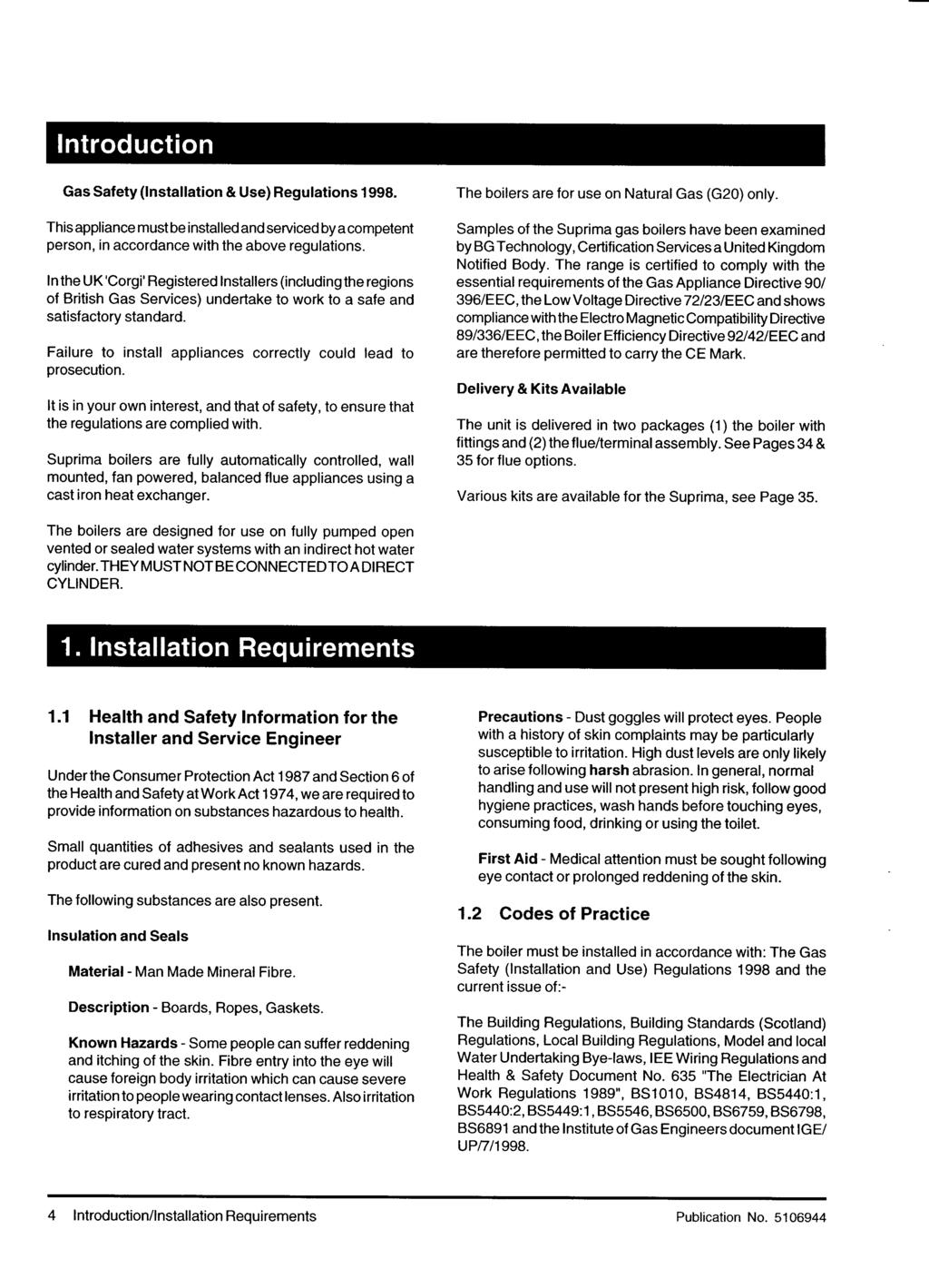
4 Introduction Gas Safety (Installation & Use) Regulations This appliance must be installed and serviced by a competent person, in accordance with the above regulations. In the UK 'Corgi' Registered Installers (including the regions of British Gas Plc) undertake to work to a safe and satisfactory standard. Failure to install appliances correctly could lead to prosecution. It is in your own interest, and that of safety, to ensure that the regulations are complied with. Suprima boilers are fully automatically controlled, wall mounted, fan powered, balanced flue appliances using a cast iron heat exchanger and are available in outputs ranging from kw (30,000-98,000 Btu/h) The boilers are for use on Natural Gas (G20) only. Samples of the Suprima gas boilers have been examined by Gastec, a United Kingdom Notified Body. The range is certified to comply with the essential requirements of the Gas Appliance Directive 90/396/EEC, the Low Voltage Directive 72/23/EEC and shows compliance with the Electro Magnetic Compatibility Directive 89/336/EEC, the Boiler Efficiency Directive 92/42/EEC and are therefore permitted to carry the CE Mark. Delivery & Kits Available The unit is delivered in two packages (1) the boiler with fittings and (2) the flue/terminal assembly. See pages 38 & 39 for flue options. Various kits are available for the Suprima range of boilers, see pages 40 & 41. The boilers are designed for use on fully pumped open vented or sealed water systems with an indirect hot water cylinder. THEY MUST NOT BE CONNECTED TO A DIRECT CYLINDER. 1. Installation Requirements 1.1 Health and Safety Information for the Installer and Service Engineer Under the Consumer Protection Act 1987 and Section 6 of the Health and Safety at Work Act 1974, we are required to provide information on substances hazardous to health. Small quantities of adhesives and sealants used in the product are cured and present no known hazards. The following substances are also present. Insulation and Seals Material - Man Made Mineral Fibre. Description - Boards, Ropes, Gaskets. Known Hazards - Some people can suffer reddening and itching of the skin. Fibre entry into the eye will cause foreign body irritation which can cause severe irritation to people wearing contact lenses. Also irritation to respiratory tract. Precautions - Dust goggles will protect eyes. People with a history of skin complaints may be particularly susceptible to irritation. High dust levels are only likely to arise following harsh abrasion. In general, normal handling and use will not present high risk, follow good hygiene practices, wash hands before touching eyes, consuming food, drinking or using the toilet. First Aid - Medical attention must be sought following eye contact or prolonged reddening of the skin. 1.2 Codes of Practice The boiler must be installed in accordance with: The Gas Safety (Installation and Use) Regulations 1998 and the current issue of:- The Building Regulations, Building Standards (Scotland) Regulations, Local Building Regulations, Model and local Water Undertaking Bye-laws, IEE Wiring Regulations and Health & Safety Document No. 635 "The Electrician At Work Regulations 1989". 4 Introduction/Installation Requirements Publication No
5 1.3 Gas Supply The meter and supply pipes must be capable of delivering this quantity of gas in addition to the demand from any other appliances in the house and must be governed at the meter. The complete installation must be tested for gas soundness and purged as described in BS Electricity Supply 230V ~ 50Hz via a fused double pole switch with a contact separation of at least 3 mm in both poles adjacent to the boiler. Power consumption is approximately 150W (inc. pump). There must be only one common isolator for the boiler and its control system and it must provide complete electrical isolation. Fuse the supply at 3 A. The minimum requirement for the power supply cable is that it should be a PVC sheathed cord at least 0.75 mm² (24 x 0.2 mm) (code designation HO5 VV-F or HO5 VVH2-F) as specified in table 16 of BS6500:1984. All wiring external to the boiler shall comply with the latest IEE Wiring Regulations, and any local regulations which apply. WARNING: THIS APPLIANCE MUST BE EARTHED. In the event of an electrical fault after installation of the boiler, preliminary electrical systems checks must be carried out i.e. Earth Continuity, Short Circuit, Polarity and Resistance to Earth. 1.5 Location of Boiler The boiler is not suitable for external installation unless it is suitably protected. If the sealed system kit is being used, this should be installed first. See instructions supplied with kit. The boiler must be installed so that the flue terminal is exposed to the external air. It is important that the position of the terminal allows the free passage of air across it at all times. The boiler must be mounted on a flat wall which is sufficiently robust to take the weight of the boiler. The boiler is suitable for installation to a combustible wall e.g. wood cladding, provided that the flue duct is not closer than 25 mm to combustible material. A metal sleeve should be installed to surround the flue duct to provide a 25 mm annular space. Further guidance is given in BS5440:1:2000, sub-clause 4.4. If the boiler is to be installed in a timber framed building it should be fitted in accordance with the Institute of Gas Engineers document IGE/UP/7/1998 (also, British Gas Service publication Part 19 - Building and Kitchen Work). If in doubt advice must be sought from Potterton. The boiler may be installed in any room, although particular attention is drawn to the requirements of the current IEE Wiring Regulations and, in Scotland, the electrical provisions of the Building Standards applicable in Scotland with respect to the installation of the boiler in a room containing a bath or shower. Where a room-sealed appliance is installed in a room containing a bath or shower, any electrical switch or appliance control, utilising mains electricity should be so situated that it cannot be touched by a person using the bath or shower. Where the installation of the boiler will be in an unusual position, special procedures may be necessary and BS6798 and BS5546 give detailed guidance on this aspect. A cupboard or compartment used to enclose the boiler must be designed and constructed specifically for this purpose. An existing cupboard or compartment may be used provided that it is modified for the purpose. Details of essential features of cupboard/compartment design including airing cupboard installations are given in BS6798 and BS5546 and should be complied with. The boiler requires only the clearances shown on Page 6, after installation. Publication No Installation Requirements 5
6 Fig. 1 6 Installation Requirements Publication No
7 1.6 Air Supply The air requirements must meet BS 5440 Part 2. The room in which the boiler is installed does not require a purpose provided air vent Ventilated Cupboard/Compartment: If the boiler is installed in a cupboard or compartment (with the exception of those installations covered by Section 1.6.2), permanent air vents are required in the cupboard or compartment, one at high level and one at low level, either direct to the outside air or to a room. Both high level and low level air vents must communicate with the same room or must be on the same wall to outside air. Both the high level and low level vent must each have a free area as stated below. The free area of each vent may be halved if the ventilation is provided directly from outside. Models: 30: 99 cm² 40: 133 cm² 50: 169 cm² 60: 198 cm² 70: 231 cm² 80: 264 cm² 100: 323 cm 2 If the boiler is installed in a cupboard or compartment with a door, allow at least 15 mm clearance between the front of the boiler and the door for air movement Unventilated Compartment: The 30, 40 and 50 models can be installed in an unventilated compartment providing the following conditions are met and no other heat sources are present within the compartment: 1.7 Flue Systems Maximum Horizontal flue length from turret: 560 mm Minimum clearances for alternative configurations Front 280 mm or Front 490 mm Side 75 mm Side 175 mm Bottom 250 mm Bottom 100 mm Top 450 mm Top 265 mm Horizontal The flue/terminal assembly supplied is suitable for a wall thickness of between 150 mm and 300 mm. A flue/terminal assembly suitable for a wall thickness of up to 550 mm is also available. Both the flue/terminal assemblies are telescopic and the minimum lengths (150 mm/6 in) are achieved by cutting. Ensure that the same length is removed from the inner and outer tubes to maintain a 20 mm overlap (minimum). 1 m flue extensions are available. Under no circumstances should the total flue length exceed m, models m, 100 model No bends allowed. Vertical 1. Twin Tube system, models only. Maximum actual length 7 m (7 extensions) Maximum equivalent resistance = 7 m Combination Flue System 2. Vertical Concentric system models - Maximum actual length 3.4 m, equivalent resistance = 3.4 m. 100 model - Maximum actual length 1.4m, No bends allowed. Combined horizontal & vertical concentric system for models only. Maximum actual length 3.4 m, maximum equivalent length 3.4 m. Note: All flue lengths quoted refer to straight lengths. For the effects of bends and offsets see Section 2.2 'Install the Flue' or the appropriate flue instructions. Publication No Installation Requirements 7
8 1.8 Flue Terminal Location K,N R Q G L G M C G D E A S G F P H A G J A F J K,N FLU0002A Fig. 2 Likely flue positions requiring a flue terminal guard Where a horizontal flue is sited less than 2m above a balcony, above ground, or above a flat roof to which people have access, a suitable terminal guard must be fitted. This serves two purposes, to protect the terminal against damage or interference and to protect passers-by. A terminal guard is available (Sales Code: PTERMGUARDEF), this should be fitted centrally about the terminal. Note: Where a flue terminal is installed less than 1 metre from a plastic, or painted gutter, or 500 mm from painted eaves, an aluminium shield 1 metre long, should be fitted to the underside of the gutter or painted surface. A suitable wall plate should be fitted to the painted wall surface of a mobile home. IMPORTANT: It is absolutely ESSENTIAL, to ensure that products of combustion discharging from the terminal cannot re-enter the building, or any other adjacent building, through ventilators, windows, doors, natural air infiltration, or forced ventilation/air conditioning. If products of combustion are found to be re-entering any building, the appliance MUST be turned OFF IMMEDIATELY. Terminal Assembly 300 min. 300 min. FLU0005A Terminal Position with Minimum Distance (mm) Fanned Draught Balanced Flue A B C D E F G H J K L M N P Q R S Directly below an opening, air brick, opening window etc Above an opening, air brick, opening window, etc Horizontally to an opening, air brick, opening window etc Below a gutter, or sanitary pipework Below the eaves Below a balcony or carport roof Above ground, roof or balcony level From vertical drain/soil pipe work From an internal or external corner From a surface facing a terminal Vertically from a terminal on the same wall Horizontally from a terminal on the same wall From a terminal facing the terminal From an opening in a carport (e.g. door, windows) into the building From adjacent wall to flue (vertical only) From internal corner to flue (vertical only) Below eaves or balcony (vertical only) Reduced Clearances This range of boilers has been tested and approved for use with certain clearances less than those shown above. Only one of these reductions may be used on a single installation. D Below a gutter, or sanitary pipework 25 E Below the eaves 25 F Below a balcony or carport roof 25 H From vertical drain/soil pipe work 25 J From an internal or external corner 25 Top View Rear Flue Fanned Draught Top View Side Flue Fanned Draught Note: The distance from a fanned draught appliance terminal installed parallel to a boundary may not be less than 300 mm in accordance with the diagram on the left. Property Boundary Line 8 Installation Requirements Publication No
9 1.9 The System Before installing a new boiler to an existing system treat the system with an appropriate descaling/flushing agent as per the instructions supplied with the treatment package. It is recommended that any corrosion inhibitors and descalers/ flushing agents used are manufactured by Fernox or BetzDearborn. If plastic pipe is used for the central heating circuit there must be a run of at least 2m of uninsulated copper pipe from the boiler flow and return connections. The boiler must be used on Indirect Fully Pumped systems only, which may be sealed or open vented - See Page 12 for pump requirements. The system should be designed so that the maximum static head does not exceed 30.5 m (100 ft) and a minimum of 150 mm (6 in). The flow pipe from the boiler must always be level to or higher than the return pipe. On all systems the pump live connection should be wired to the boiler terminal block, it will then be controlled by the pump over-run. This will ensure that the pump will continue to run after boiler shut down if the water temperature is high, thus preventing nuisance operation of the overheat thermostat. It is important that where electrically operated zone valves are used the boiler is wired so it does not cycle when the zone valves are closed. Also, systems fitted with controls that close both hot water and central heating circuits while the boiler is still hot, must be fitted with a by-pass circuit to dissipate the residual heat from within the boiler. If a three port valve is used as shown in Fig. 5 a by-pass is not necessary since one circuit is always open. Where a pair of two port valves are used, a by-pass is necessary. The total length of the by-pass circuit taken from the boiler connections should be greater than 4 metres of 22 mm pipe. It should be fitted with a lockshield valve and be adjusted to maintain a minimum flow through the boiler of 4.5 litres/min (1 gal/min). Systems fitted with controls which allow the boiler to operate when both the hot water and central heating circuits are closed (i.e. mechanically operated thermostatic control valves) must be fitted with a by-pass circuit (2 m min. length of 22 mm dia. pipe) and capable of maintaining a minimum water flow rate through the boiler of 9 litres/min (2 gal/min). A suggested method of meeting these requirements by using a bathroom radiator fitted with two lockshield valves is shown in Fig. 5. Additional system information can be found in the Control Systems, pipework and Wiring Guide. Drain off taps should be fitted in the pipework close to the boiler and in the low points of the system. Note: Although the system can be emptied using the drain off taps installed in the pipework around the system, to empty the boiler it is necessary to remove the drain off screw positioned on the heat exchanger. Sealed Systems Note: If the sealed system kit is Not being used the installation must comply with the following requirements. Installation The installation must comply with the requirements of BS 6798: 1987 and BS 5449: Pt 1. The British Gas publication "British Gas Specification for Domestic Wet Central Heating Systems" should also be consulted. Pressure Relief Valve A non-adjustable spring-loaded pressure relief valve, preset to operate at 3 bar (45lbf/in²) shall be used. It must comply with BS 6759: Pt 1. and include a manual testing device. It shall be positioned in the flow pipe either horizontally or vertically upwards and close to the boiler. No shut-off valves are to be placed between the boiler and the safety valve. The valve should be installed with a discharge pipe which permits the safe discharge of steam and hot water such that no hazard to persons or damage to electrical components is caused. Pressure Gauge A pressure gauge incorporating a fill pressure indicator, covering the range 0-4 bar (60 lbf/in²) shall be fitted to the system. It should be connected to the system, preferably at the same point as the expansion vessel. Its location should be visible from the filling point. Expansion Vessel A diaphragm type expansion vessel to BS 4814: Pt 1. shall be fitted close to the inlet side of the pump. The connecting pipework should not be less than 15 mm. Pipework connecting the expansion vessel should not incorporate valves of any sort. Methods of supporting the vessel are supplied by the vessel manufacturer. The nitrogen or air charge pressure of the expansion vessel shall not be less than the hydrostatic head, (height of the top point of the system above the expansion vessel). To size the expansion vessel it is first necessary to calculate the volume of water in the system in litres. The following volumes may be used as a conservative guide to calculating the system volume. Boiler Heat Exchanger: 2.1 litres Small Bore Pipework: 1 litre per kw of system output Micro Bore Pipework: 7 litres Steel Panel Radiators: 8 litres per kw of system output Low Water Capacity Radiators: 2 litres per kw of system output Hot Water Cylinder: 2 litres Publication No Installation Requirements 9
10 If the system is extended, the expansion vessel volume may have to be increased unless provision has been made for extension. Where a vessel of the calculated size is not available, the next available larger size should be used. The boiler flow temperature is controlled at approximately 82 C. The vessel size can now be determined from the information in Table 1 where V = System volume in litres. Vessel Charge Pressure (bar) Initial System Pressure (bar) Expansion Vessel Volume (litres) Table V x V x Cylinder The hot water cylinder must be an indirect coil type or a direct cylinder fitted with an immersion calorifier suitable for operating at a gauge pressure of 0.3 bar (5 lbf/in²) in excess of safety valve setting. Single feed indirect cylinders are not suitable for sealed systems. Method of Make-up for sealed systems Provision shall be made for replacing water loss from the system either:- i) from a make-up vessel or tank mounted in a position higher than the top point of the system, and connected through a non-return valve to the system on the return side of the hot water cylinder or the return side of all heat emitters, see Fig.6. or Fig. 3 ii) where access to a make-up vessel would be difficult by using the mains top up method or a remote automatic pressurisation and make-up unit as shown in Figs. 3 & 4. Mains Connection There shall be no connection to the mains water supply or to the water storage tank which supplies domestic hot water even though a non-return valve, without the approval of the Local Water Authority. Filling Point The system shall be fitted with a filling point at low level which incorporates a stop valve to BS 1010 and a double check valve of an accepted type to be fitted in this order from the system mains, see Fig. 3. Fig Installation Requirements Publication No
11 Fig. 5 Publication No Installation Requirements 11 Fig. 6
12 Circulation Pump Selection The resistance through the heat exchanger when operating with a water flow rate producing an 11 C temperature rise at maximum boiler output are shown in the table. If other controls such as three position valves are used in the system, the resistance through them, quoted in their manufacturers literature must be taken into account. The pump may be fitted on either the flow or return and MUST be wired directly to the boiler terminal block. It must be fitted with two isolating valves which are positioned as close to the pump as possible. Closing of any valve must always leave the open vent unobstructed Water Flow Rate l/min Boiler Resistance mbar m Installation 2.1 Unpack & Prepare the Boiler These instructions assume you have decided on where the boiler will be located and the type of flue system to be used. 1. Carefully unpack the boiler. 2. Do not discard any packaging until all the items are accounted for. 3. Open the controls cover, remove the securing screw and washer, pull off the controls cover and put safely aside. 4. Remove two screws and washers, remove the white front case and put safely aside. 5. Place the mounting template in the proposed boiler position ensuring that it is level. Minimum clearances are accounted for on the template. 6. Mark the flue hole, remove the template and carefully cut the flue hole through the wall. 12 Installation Requirements/Installation Publication No
13 F R 7. Replace the template centrally over the hole (ensure template is level), mark two screw fixing hole positions for the mounting bracket and one for the securing point. 8. Remove the template, drill (7 mm drill) and plug the three holes. 9. Secure the mounting bracket to the wall using two No. 12 x 2" woodscrews. 10.Lift the boiler onto the mounting bracket, slide both boiler securing clips over the mounting bracket (this prevents the boiler from being accidently lifted off the the mounting bracket), see Fig.7. To square the boiler to the wall adjust the boiler alignement screws on the back panel of the boiler. 11.The third screw provided is also to prevent the boiler from being lifted off the mounting bracket, once the boiler is mounted on the wall. This screw can be replaced by an anti-theft kit see note below. Boiler Mounting Bracket Boiler Securing Clip fdthyjkllkhklkyj fdthyjkllkhklkyj fdthyjkllkhklkyj fdthyjkllkhklkyj Literature Pack Note: There is provision for an anti-theft securing point (sales code: SUPKITP) which may be used if required. 2.2 Install the Flue Maximum equivalent flue lengths are as follows: Models - 3.4m, 100 Model m (no bends allowed). These instructions are for rear and side flue applications. Rear Flue 1. Measure the wall thickness and add 66mm (or 106mm for installations using the System Boiler or Stand Off Kits). Boiler Minimum Clearance Flue Tube Wall Template Side Flue 1. Determine the X dimension (wall thickness + distance to boiler centreline). For both Rear & Side Flues 2. Extend the telescopic flue to the required length, minimum 20 mm overlap. 3. Drill through the pilot hole and secure with self tapping screw. 4. Wrap tape around the joint on the outer duct to seal the flue, slide drip ring into a position to coincide with the air gap in the wall (cavity wall). 5. Slide the flue through the hole until it stops on the pin. 6. The boiler is supplied with the flue elbow set to the rear. For side outlet slacken the screws and turn the elbow to the required position and re-tighten screws. Ensure that the seals are still correctly located. 660mm Minimum Clearance Fixings Poly Bag Boiler Mounting Bracket Boiler Securing Point 410mm Minimum Clearance SUP0010B Fig. 7 Publication No Installation 13
14 7. Slide the flue back until it engages in the elbow bayonet connection, twist anticlockwise to lock. 8. Drill through pilot hole and lock flue in position with the self tapping screw provided. 9. Make good the wall around the flue, both outside and inside. For extension kits refer to pages 38 & 39. If a Horizontal Extension is required this MUST be combined with a Standard Flue as shown below in the Maximum Flue Length Guide. If a in-line bend is required in the flue the following rules apply: A 90 in-line bend is the equivalent to a 1m length of flue. A 135 in-line bend is the equivalent to a ½m length of flue. The maximum equivalent flue resistance allowed when using bends is: models - 3.4m, 100 model - not allowed. Note: For flue lengths less than the minimum telescopic length, the tubes can be cut to suit. Ensure that the same length is removed from the inner and outer tubes to maintain a 20 mm overlap (minimum). For further information see the publications supplied with the flue system. Fig Installation Publication No
15 2.3 Connect the Power Supply Cable PIN 87ARXXX POTTERTON 9016 SUPRIMA 30 L G.C. No BOILER CODE No. ALVG Input (GROSS) Q = kw Btu/h Output P = kw Btu/h 9.30 mbar Burner Pressure (HOT) 3.70 in. wg Gas Rate cu. m/h cu. ft/h Injector Size 2.8mm Dia. NO x CLASS 3 Type - C 12 C 32 C 71 PMS = 3.0 bar IP 20 2H 230V ~ 50Hz. 2H - G20-20 mbar 80W 3A Fuse 01 THIS APPLIANCE IS INTENDED EXCLUSIVELY TO BE INSTALLED ON A SUPPLY WITH A GOVERNED METER COUNTRY OF DESTINATION - GB, IE. Baxi Heating Ltd Cable clamping is provided on the front of the controls panel. Feed the cables up and over the back of the chassis, through the clamp and into the terminal connection. Connect the wires, brown to L, blue to N and green/yellow to earth ( ). Note: When connecting the power supply cable, ensure that the length of the earth wire is such, that if the power supply cable pulls out of the cable clamp the live and neutral wires become taut before the earth wire. 2. The pump wiring should be routed through the hole in the base of the rear cover, through the cable clamp and connected to the terminal connection. 3. Take up excess slack in the cables between the terminal block and the cable clamp, then tighten the cable clamp screws. Ensure sufficient slack is available to the cable clamps to allow the control panel to hinge freely. Check by opening the control panel. If fitting the optional integral programmer go to section 2.4 before performing steps 4 and 5 below. 4. Secure the controls assembly to the chassis using the screw previously removed. 5. Carry out preliminary electrical system checks i.e. Earth Continuity, Short Circuit, Polarity and Resistance to Earth. Frost Thermostat: If a Frost Thermostat is to be fitted, the connections should be made in the wiring external to the boiler. The Frost Thermostat should be connected between the Permanent Live & Switch Live in the mains terminal block on the boiler. Do not switch on the electricity supply at this stage. SUP0262B Fig. 9 Publication No Installation 15
16 2.4 Install the Optional Programmer 1. Install the programmer as shown in the instructions supplied with it. 2.5 Connect the Gas Supply Ensure that the gas supply is isolated. Connect the gas supply using a suitable adaptor to the gas valve or 15 mm copper tail (100 model). Important: To prevent damage to the 'O' ring, do not solder the fitting whilst assembled to the gas valve. The pipe diameter required will depend on the boiler model and the pipe length from the gas meter. Ensure that the gas supply pipe is selected in accordance with BS 6891 so that an adequate gas supply to the boiler is provided. Do not turn the gas supply on at this stage. Fig. 10 Front View SUP0021B Gas Valve Gas Valve Gas Valve Closed Open All Dimensions in mm When Soldering Remove 'O' Ring Fitting Side View DO NOT Solder The Fitting Whilst Assembled To The Gas Valve Gas Valve Gas Cock Rc ½" ½" B.S.P. Female Securing Screws Fig model models 16 Installation Publication No
17 2.6 Connect the Water System 1. Connect system pipework to the boiler, compression fittings should be used. Note: Drain off taps should be installed close to the boiler and at the lowest points in the system. Fig. 12 Publication No Installation 17
18 3. Commissioning PIN 87ARXXX POTTERTON 9016 SUPRIMA 30 L G.C. No BOILER CODE No. ALVG L Model Shown Input (GROSS) Q = Output P = Burner Pressure (HOT) kw Btu/h kw Btu/h mbar in. wg cu. m/h cu. ft/h Gas Rate Injector Size 2.8mm Dia. NO x CLASS 3 Type - C 12 C 32 C 71 PMS = 3.0 bar IP 20 2H 230V ~ 50Hz. 2H - G20-20 mbar 80W 3A Fuse 01 THIS APPLIANCE IS INTENDED EXCLUSIVELY TO BE INSTALLED ON A SUPPLY WITH A GOVERNED METER COUNTRY OF DESTINATION - GB, IE. Baxi Heating Ltd L Model Shown Gas Pressure adjuster Gas Valve 50 L Model Shown SUP264A Fig Commissioning Publication No
19 100 model shown Gas Pressure adjuster Fig. 14 Important The commissioning and boiler adjustment must only be carried out by a suitably qualified personnel. Potterton offer this service on a chargeable basis. Important When checking for gas soundness open all windows and doors in the room. Extinguish all naked lights, cigarettes, pipes, etc. Publication No Commissioning 19
20 3.1 Commission the Boiler Open Vented Systems - Remove the pump and flush the system thoroughly with cold water. Re-fit the pump. Fill and vent the system then check for leaks. Sealed Systems - Remove the pump and flush the system thoroughly with cold water. Re-fit the pump. Fill and vent the system until the pressure gauge registers 1.5 bar (21.5 lbf/in²) and check for leaks. IMPORTANT: The pressure relief valve is factory tested and does not need testing during the commissioning of the boiler. It must not be used to reduce system pressure as it may cause debris in the system to foul the valve. All Systems Warning: Before lighting the boiler, ensure that the outer white case has been correctly fitted and that the sealing strip fitted to the outer white case is forming a tight seal with the main boiler chassis. The controls cover is left off at this stage. Preliminary electrical system checks These checks must be carried out before attempting to light the boiler. They are:- Commission Earth Continuity, Short Circuit, Polarity & Resistance to Earth. 1.The whole of the gas installation must be checked for soundness and purged in accordance with BS Set the boiler temperature control knob to 'O' Standby. 3. Turn the boiler gas service cock to the 'On' position and ensure that the main gas supply is turned 'On'. 4. Make sure that the system is full of water and that the pump and radiator isolating valves are open. Vent air from the system. 5. Ensure that the main electricity supply is 'On'. 6. Check that the time control, if fitted, is in an 'On' position and that the room and cylinder thermostat, where fitted are set to high temperatures. First time lighting: 7. Set the temperature control knob to its maximum setting. The boiler will attempt to light, if the boiler does not light within 3 attempts (due to air in the system) the boiler controls will go to 'Lockout' and the upper Red LED on the control panel will go to a rapid flashing mode. To re-start the lighting sequence press the reset button on the control panel. There will be a short delay before the lighting sequence starts. When the burner flame has established lower Green LED on the user control panel will be on continuously. LED Indicators Status Green LED Red LED Mains ON Only OFF ON Ext. Call for Heat FLASHING ON (Boiler set to STNDBY, 2 Per Sec. Temp. Control set to 'O' Off) Ext. Call for Heat FLASHING OFF (STNDBY switch to ON, 2 Per Sec. Temp. Control set to Max.) Ignition FLASHING OFF (i.e. Gas and Sparks ON) 16 Per Sec. FLAME Detected ON OFF Boiler Temperature FLASHING ON Control Satisfied 2 Per Sec. 8. With the main burner running, check for gas soundness using leak detection fluid. 9. Allow the system to reach maximum working temperature and examine for water leaks. Set the temperature control to 'Standby' and drain the system whilst still hot. Note: Should the boiler fail to operate correctly refer to the Fault Finding Guide and the boiler wiring diagram for further information. 10. Re-fill and vent the system making a final check for leaks. 11. On sealed systems adjust to the correct cold fill pressure. Set the pressure gauge pointer to the system design pressure. 12. If a by-pass circuit is fitted the by-pass valve should be adjusted so as to maintain sufficient water flow through the boiler to ensure that the overheat thermostat does not operate under normal conditions. 20 Commissioning Publication No
21 13. If the boiler fails to operate Check the LED indicator fault modes below and refer to fault finding guide and boiler wiring diagram. LED Indicators Fault Modes Status Green LED Red LED Blocking - Mains Frequency ON FLASHING incorrect or Air Switch Fault 2 Per Sec. > 1 min. or Reset button held in to force a restart Earth Fault or FLASHING FLASHING Mains Reversal 2 Per Sec. 2 Per Sec. Lockout OFF FLASHING 2 Per Sec. 3.2 Final Adjustments 1. Use a pressure gauge to check the inlet and burner pressures. See the Data Badge for figures. 2. Turn the boiler on and allow to run for 10 minutes. 3. Check that the inlet pressure is 20mbar. 4. Check that the burner pressure is in accordance with the information on the boiler data badge. The gas valve is factory set, but if adjustment is required follow Section or Check at the gas meter that the gas rate is correct. 6. Set the temperature control knob to 'O' Standby and check that the main burner shuts down. Remove the pressure gauges, re- fit the screws and check for gas soundness. 7. Re-fit the controls cover and secure with the screw previously removed. Control Thermostat Other Boiler Controls No further setting or checking is necessary as all boiler mounted controls are designed so that if a fault should occur they will fail safe. External Controls Check that any other external controls connected in the system, such as clocks or thermostats, control the boiler are set as required. 3.3 Advise the User On completion of the installation, the installer should demonstrate the operation of the boiler and its associated controls. Also hand over all the instructions. 1. If a programmer is fitted, set the time and programme the required settings as shown in the instructions supplied with the programmer. 2. Advise the user of the precautions necessary to prevent damage to the system and to the building in the event of the system remaining inoperative during frost conditions. 3. Advise the User that for continued efficient and safe operation of the boiler it is important that adequate servicing is carried out at least once a year by a Potterton Service Engineer, the local Gas Supplier or a C.O.R.G.I. Registered Installer. 4. Leave a permanent card attached to the boiler giving: a. Name and address of installer. b. Date of installation. c. A wiring diagram of the external control circuit. 5. And finally, complete the Benchmark Log Book and hand over all the instructions supplied. At its minimum and maximum settings, the thermostat should control the water flow temperature at approximately 57 C - 82 C. Overheat Thermostat The overheat thermostat is pre-set and no adjustment is possible. It will require manual re-setting if an overheat condition occurs (the LED will go to flashing Red). The re-set button is located on the controls assembly. Publication No Commissioning 21
22 4. To Service the Boiler & Component Replacement To ensure continued efficient operation of the appliance, it is recommended that it is checked and cleaned as necessary at regular intervals. The frequency of servicing will depend upon the particular installation conditions and usage but in general once per year should be adequate. It is the law that any service work must be carried out by a competent person who is C.O.R.G.I. Registered. Before servicing, fire the appliance and check that the flames are blue and stable. Yellow flame and excessive lifting indicate poor combustion. WARNING: Before commencing work turn the temperature control knob to 'O' Off and allow the appliance to cool, isolate the electricity supply. If the gas valve is to be removed turn off the gas supply at the appliance service cock. IMPORTANT: Always test for gas soundness after completing any servicing of gas carrying components and carry out functional checks of controls. IMPORTANT: Ensure that the outer white case is correctly fitted and that the sealing strip fitted to the door is forming a tight seal with the boiler casing. Remember to fill in the Benchmark Log Book Notes on Cleaning Boiler Components Heat Exchanger: Place a sheet of paper under the heat exchanger then using a flat blade tool (Part No ), scrape the flueway fin surfaces in a downward movement. This will ensure that most of the deposits will be collected on the paper. Burner: Brush the burner top and check that the flame ports are clear. Any blockage may be removed with a fine wire brush. Turn the burner upside down and tap gently to remove any debris (Protect the electrode). Electrode: If the electrode requires cleaning wipe the surface using a solvent. Main Injector: Omit this operation if the gas rate is correct, otherwise clean by blowing through. Do NOT clear the injector with a pin or wire. Fan Assembly: Examine the fan impellor and carefully clean if necessary. Flue: Inspect the flue terminal and flue/air tube for blockage and integrity, rectify if necessary. 4.1 General Access Warning: Before starting work, open the controls cover and set the temperature control knob to 'O' Off. Isolate the electricity supply and if a gas carrying component is to be removed, isolate the gas supply at the appliance service cock. Allow the boiler to cool. Important: Always test for gas soundness after completing any exchange of gas carrying components and carry out a functional check of the controls. Re-assemble all parts in reverse order. 1. Remove the securing screw and slide off the controls cover. Put safely aside. To complete sections to perform the following:- 22 To Service the Boiler & Component Replacement Publication No
23 2. Remove the two screws securing the outer white case to the chassis. Hinge forward, pull bottom of cover forward and lift off. Put safely aside. 4.2 To Service the Boiler 1. Note how it fits and disconnect the tube from the front of the fan housing. Flue Gas Sampling Points 3 Slide the side panel forward and lift-off casing Unscrew the side panel securing screw 2 2. Disconnect the wires from the fan motor. 3. Remove the two screws securing the fan to the flue hood. Carefully pull the fan down and away from the flue hood. 4. Remove the flue hood. 5. Remove the screw securing the combustion chamber front to the heat exchanger and remove the panel. 6. Disconnect the electrode and earth wire. 7. Undo the fixing screw, hold the burner at the right hand side and pull forward to disconnect from the box. If necessary, remove the injector(s), refer to Sections (30-80) or (100). The heat exchanger, burner and fan can now be inspected. If deposits have formed on these items and on ancillary components clean as detailed in the notes at the start of this section. 4 Unscrew the front cover securing screws 4.3 Component Replacement (see over page) 5 Open the controls door SUP0013C Hinge forward, pull bottom of the cover forward and lift-off 1 Fig. 15 The boiler can be re-assembled in reverse order. Ensure that any electrical connections are in place and that any damaged seals or insulation are replaced before re-fitting the controls cover. Check the gas pressure, refer to Section (30-80) or (100). Other Components No other servicing is required on any other boiler component. Warning Before attempting to remove any component from the appliance first disconnect the mains electricity supply by removing the plug from the wall socket or by switching off the appliance at the external isolating switch. The 'O' (off) position on the boiler temperature control will leave parts of the boiler Live. If the appliance gas valve is to be removed it will be necessary to isolate the gas supply at the appliance isolating valve. Important After removal or replacement of any gas carrying component a test for gas soundness must be made and functional check of the controls carried out. Important Any 'O' rings, seals or gaskets disturbed during replacement of parts must be visually inspected and replaced if worn or damaged. Publication No To Service the Boiler & Component Replacement 23
24 4.3.1 Electronic Control Board Gain General Access - See Remove the securing screw and allow the control panel to pivot forwards. 2. Disconnect all connectors and wires, unscrew the four securing screws and remove the board. 3. On re-assembly refer to the wiring diagram when re-connecting wires and connectors Air Pressure Switch Gain General Access - See Remove the securing screw and allow the control panel to pivot forwards. 2. Note the wire connections and disconnect the wires to the air pressure switch. 3. Remove the screw (access through the fan compartment) securing the air pressure switch to the chassis. 4. Re-assemble in reverse order Electrode Gain General Access - See Pull the electrode lead off the electrode, remove the securing screw and remove the electrode. 2. On re-assembly check the gap between the electrode tip and the burner face. It should be 3-4 mm. If required adjustment can be made by careful use of pliers. Fig To Service the Boiler & Component Replacement Publication No
25 4.3.4 Burner models Gain General Access - See Disconnect the electrode lead and earth wire. 2. Undo the fixing screw, hold the burner at the right hand side and pull forwards to disconnect from the air box. 3. Unscrew the electrode and transfer to the new burner. 4. Re-assemble in reverse order, on reassembly hook the rear of the locating bracket (1) in place before locating the front (2) Injector models Gain General Access - See Remove the burner - See Use a 13mm (A/F) or ½" (A/F) socket spanner to remove the injector. 3. Unscrew the injector, use a new sealing washer on re-assembly. If using a flat spanner to remove the injector see the next section (4.3.6.) Combustion Chamber Insulation models Gain General Access - See The front insulation is accessible as the front is already off. 2. Remove the burner - See Remove the two screws securing the side and rear insulation assembly to the front of the chassis. 4. Pull the assembly forwards and away from the boiler. Replace insulation pieces as required, replace any securing clip if damaged. 5. Re-assemble in reverse order. Publication No To Service the Boiler & Component Replacement 25 Fig. 17
26 4.3.7 Gas Valve models Gain General Access - See Pull off the electrical connector at the valve. 2. Remove the gas cock by unscrewing the four long hexagonal head screws from the base of the valve. 3. Remove the burner - See Remove the screw securing the controls assembly to the top of the valve. 5. Remove the two screws securing the side and rear insulation assembly to the front of the chassis and remove assembly. 6. Remove the three screws securing the gas valve manifold assembly to the chassis and remove the complete assembly. 7. Remove the three M5 x 16mm screws securing the gas manifold to the gas valve. 8. Use a new 'O' ring and refit the manifold to the new gas valve. 9. Re-assemble in reverse order, use a new side panel gasket and 'O' ring in the gas cock. 10. Check that the burner pressure is in accordance with the information on the boiler data badge. If adjustment is required, turn the pressure adjusting screw anti - clockwise to increase pressure or clockwise to decrease. Gas Pressure adjuster Fig To Service the Boiler & Component Replacement Publication No
27 4.3.8 Burner 100 model Gain General Access - See Disconnect the electrode lead and earth wire. 2. Undo the fixing screw, hold the burner at the right hand side. Pull forwards and to the left, disconnect from the air box and support tab. 3. Unscrew the electrode and transfer to the new burner. 4. Re-assemble in reverse order. Locate the left hand side of the burner onto the support tab on the side insulation. Hook the rear of the locating bracket (2) in place before locating the front (3) and re-fitting the screw Combustion Chamber Insulation 100 model Gain General Access - See The front insulation is accessible as the front is already off. 2. Remove the burner - See Remove the two screws securing the side and rear insulation assembly to the front of the chassis. 4. Pull the assembly forwards and away from the boiler. Replace insulation pieces as required, replace any securing clip if damaged. 5. Re-assemble in reverse order. Fig. 19 Publication No To Service the Boiler & Component Replacement 27
28 Gas Valve 100 model Gain General Access - See Turn gas cock OFF, see ig.20. Pull off the electrical connector at the valve. 2. Remove the gas cock by unscrewing the four long hexagonal head screws from the top of the valve. 3. Remove the burner - See Remove the two screws securing the side and rear insulation assembly to the front of the chassis and remove assembly. Gas Pressure adjuster 5. Remove the three screws securing the gas valve manifold assembly to the chassis and remove the complete assembly. 6. Remove the four screws securing the gas manifold to the gas valve. 7. Use a new 'O' ring and refit the manifold to the new gas valve. 8. Re-assemble in reverse order, use a new 'O' ring in the gas cock and a new injector manifold gasket. Fig Check that the burner pressure is in accordance with the information on the boiler data badge. If adjustment is required, turn the pressure adjusting screw anti - clockwise to increase pressure or clockwise to decrease. 28 To Service the Boiler & Component Replacement Publication No
29 Injectors 100 model Gain General Access - See Remove the burner - See Use a 13mm (A/F) or ½" (A/F) socket spanner to remove the injectors. 3. Unscrew the injector, use a new sealing washer on re-assembly Fan & Flue Hood Gain General Access - See Disconnect the tube from the front of the fan housing - note how it fits. 2. Disconnect the wires from the fan motor. 100 model only, loosen the baffle plate securing screw and remove the baffle plate. 3. Remove the three screws securing the fan to the flue hood. 4. Carefully pull the fan away from the boiler. 5. Flue Hood: On re-assembly ensure that the flue hood locates under the two brackets at the rear of the chassis. Check the seal and replace if damaged. 6. Fan: On re-assembly ensure that the rubber seal around the fan opening is located correctly into the base of the flue elbow. 7. Re-assemble in reverse order. Publication No To Service the Boiler & Component Replacement 29 Fig. 21
30 Temperature Sensor Gain General Access - See Disconnect the wires from the sensor. 2. Depress the clips on the outside of the sensor and pull it clear of the pipe. 3. Re-assemble in reverse order, use fresh conducting paste Overheat Thermostat Gain General Access - See Disconnect the wires from the thermostat. 2. Unscrew the thermostat. 3. Re-assemble in reverse order. Fig To Service the Boiler & Component Replacement Publication No
31 SUP0219B Heat Exchanger Warning: For Sealed Systems relieve system pressure before draining. Gain General Access - See Drain the system at its lowest point. 2. Remove the fan and flue hood - See Remove the burner - See (30-80 models) or (100 model). 4. Hold a suitable container under the left hand side of the heat exchanger and slacken the drain plug. Drain the heat exchanger and retighten the plug. 5. Remove the screws securing the combustion chamber insulation assembly to the chassis and withdraw it. 6. Release both the flow and return nuts at the top of the heat exchanger. 7. Support the heat exchanger, remove the four bolts (Two each side) and carefully remove the heat exchanger. 8. Replace rubber seals in flow and return ports, feed the new heat exchanger into position ensuring the pipe connections are correctly located. 9. Secure the heat exchanger with the four fixing screws and tighten the two sealing nuts. Drain Plug 10.Re-assemble in reverse order. Fig. 23 Publication No To Service the Boiler & Component Replacement 31
32 5. Functional Wiring Diagram Boiler Lighting Sequence 1. Supply external voltage to boiler terminal connections L and N, 230 volts, 50 HZ. 2. Supply external voltage to boiler terminal connection, switch line SW 230 volts, 50 HZ. 3. Pump live from boiler energised, diverter/zone valves operate in accordance with system demand. 4. Boiler control checks, air pressure switch for "No Air Condition" (red light "On", green light "Flashing"). 5. If "No Air" the control switches on the fan. 6. After ten seconds air pressure switch proves fan is on. 7. Gas valves open and ignition for 3 seconds (green light flashes rapidly). 8. Boiler firing (green light "On" only). 9. If the flame is not detected at this time, the boiler will turn off. 10.The above sequence will repeat for a further two ignition attempts before going to lockout (indicated by the red light flashing). 11.Pressing the reset button will re-start boiler at No The control will continue to run the pump for several minutes after any firing of the boiler. 13.The control will run the pump automatically for a few minutes every twenty four hours to maintain the free running of the pump. 14.The standby position on the thermostat control knob will prevent the boiler firing but will permit operation of the pump for sequences 12 and 13. Fig Functional Wiring Diagram Publication No
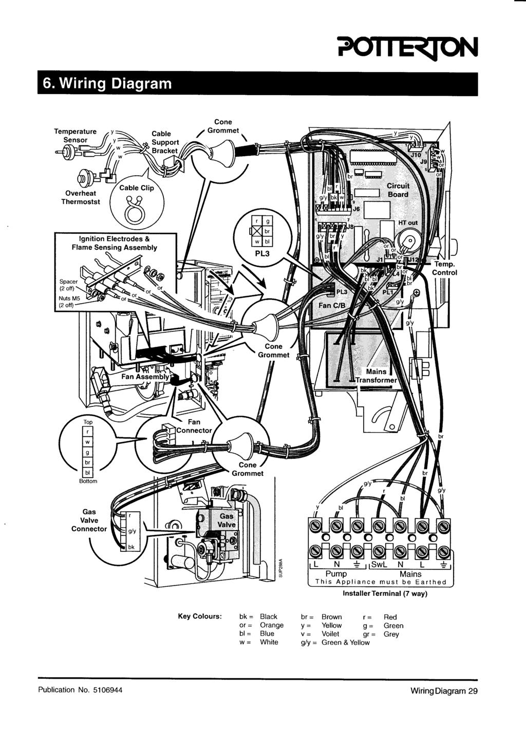
33 6. Wiring Diagram Fig. 25 Publication No Wiring Diagram 33
34 7. Fault Finding Guide Sequence of Events 1. On start-up boiler checks that a. The reset button is not stuck ON b. The Live and Neutral are not swapped c. There is no Pump Live wiring fault d. The gas valve is not energised e. There is no flame detected Note: If there is a fault the Control will go to lockout 2. Control continues to hold gas valve open until either the set temperature is reached or the switch live demand is removed 3. Pump remains energised whilst there is a demand 4. Setting control thermostat to 'O' has the same result as reaching the set temperature 5. Control checks that flame is not detected 6. Control re-starts ignition sequence Check list in the event of a fault 1. Switched Live call for heat is recognised by the Control but as boiler control thermostat is set to 'O' the ignition sequence is not started 2. Flashing Green indicates a call for heat to the user 3. Control thermostat set to call for heat 4. Control starts ignition sequence, Air Pressure Switch is checked for open circuit 5. Fan is energised 6. If APS fails to operate control goes to Blocking error (Red light flashes but no need to press reset). Control waits for APS to operate before energising gas valve and starting EHT spark 7. Control checks gas valve is energised. If valve is not energised overheat thermostat may be faulty 8. Control checks for flame detection within 3 seconds, if a flame is not detected the fan is turned off and the ignition sequence is restarted for two further attempts from '4' Intermittent Lockout - Main causes are: Other common reasons for complaint are: Switch Live connected to Pump Live Poor burner ignition due to gas pressure Poor burner ignition due to incorrect spark gap Slow opening gas valve after a long standby period Weak spark due to electrode lead or Control Pre-pay gas meter running out Other system faults (actuator, room thermostat, timer) Lack of user education in the operation of system control System wiring faults affecting operation or temperature 34 Fault Finding Publication No
35 Publication No Fault Finding 35
36 8. Short List Of Spare Parts Fig Short List Spare Parts Publication No
37 Drg. Ref. G.C. No. Description Qty. Part No a 16b Electrode Earth Lead models Earth Lead 100 model Temperature Control Gas Valve models Gas Valve 100 model (soft light) Manifold Gasket - Case/Manifold models Injector/Manifold Gasket - Case/Manifold 100 model Manifold 'O' Rings - Gas Cock (Qty 2 off on 100 model) - Manifold Flue Elbow Seal Circuit Board Thermostat Knob Pressure Switch Fan Assembly 30, 60, 70 & 100 models 40 model 50 model 80 model 30 to 40 models 50 model 60 to 70 models 80 model 100 model Overheat Thermostat Injector - Main Burner & Flue Scraper Front Panel Seal - Type 1 Front Panel Seal - Type 2 Front Panel Seal - Type 3 Fan Outlet Seal Flue Tube/Elbow Seal Temperature Sensor Fan Gasket - 30 to to 100 Fuse (Type: 3.15AT) Electrode Lead models Electrode Lead 100 model Publication No Short List Spare Parts 37
38 Flue Kits Check availability of these kits before ordering Fig Optional Extras - Flues Publication No
39 Check availability of these kits before ordering 1m Flue Extension Kit Sales Code: ULT2EXTN (Not 100 models) C E D (Max. 3 Kit) Flat Roof Flashing Kit Sales Code: PUMAKITK Pitched Roof Flashing Kit Sales Code: PUMAKITL B F A A) Extension Air Tube (Outer) D) Fixing Bracket B) Extension Flue Tube (Inner) E) Woodscrews (2 off) C) Self Tapping Screws (6 off) F) Wall Plugs (2 off) 90 In-Line Bend Kit Sales Code: PUMAKITB (Not 100 models) C D B A 135 In-Line Bend Kit Sales Code: PUMAKITC (Not 100 models) A) 90 or 135 In-Line Elbow B) Product Tube 'O' Ring (2 off) C) Air Tube Clamp (Including Nuts & Screws) D) Air Tube Seal (2 off) Min. Offset Flue Kit Sales Code: 3SUPKIT C F B D A E G A) Terminal Elbow B) Terminal Adaptor C) Terminal Assem. D) Drip Ring E) Sealing Tape F) Screw Pack G) Wall Template Concentric Vertical Flue Adaptor Kit Sales Code: SUPKITC (Not 100 models) Wall Plate Pack Sales Code: SUPKITB 1m Twin Tube Flue Twin Tube 90 Extension Kit In-Line Bend Kit Sales Code: Sales Code: PUMAKITH PUMAKITI (Not 100 models) (Not 100 models) A) Extension A) 2 off- 90 In-Line Bend Tubes (2 off) B) Fixing Brackets (2 off) B A Twin Tube135 In-Line Bend Kit Sales Code: PUMAKITJ (Not 100 models) A) 4 off-135 In-Line Bend A A Internal Fitment Kit Sales Code: SUPKITA D B C A E E A) Flue Liner B) Rubber Seal C) Screws & Plugs D) Rope E) Retaining Collars Terminal Guard Sales Code: PTERMGUARDEF Installation instructions included as necessary with each kit. Telescopic In-Line Bend Adaptor Sales Code: SUPKITR (Not 100 models) SUP0038D Fig. 28 Publication No Optional Extras - Flues 39
40 MID 3 bar System and Other Kits Installation instructions included as necessary with each kit Suprima System Kit Sales Code: SUPSYSKIT (*Items not included in this kit) SUPSYSKITDV (Complete kit shown below) Wall Template *Wiring Diagrams Top Feed System Pipework (only for SUPSYSKIT) Sales Code: SUPSYSKITTOP 22mm Pipework 22mm Nut & Olive Instructions Instructions System Pod Kit Sales Code: SUPSYSPODA (Internal Fitment Kit, Pod Kit & Isolation Cock) SUPSYSPODB (Pod Kit only) SUPSYSPODC (Pod Kit & Isolation Cock) Isolating Cock (Isolation Kit Only) Wall Template *Junction Box & Bracket Pump System Mounting Frame Instructions Expansion Vessel M A N UA L O VERRIDE ONLY AUTO DHW PORT B CH PORT A COM PA CT Return Pipe Ass. *Divertor Valve & Pipework Fixing Pack Infill Panels Flow Pipe Assy. Return Pipe Assy. Flexible Hose System Case SUP0248A Fig. 29 Check availability of these kits before ordering 40 Optional Extras - General Publication No
41 Check availability of these kits before ordering Flue Turret Cover Sales Code: SUPKITI Removeable Panel For Side Flue Outlet Boiler Stand Off Kit Sales Code: SUPKITJ Stand Off Frame Boiler Mounting Bracket 122mm Boiler Securing Screw Programmer Kit Sales Code: SUPKITH Anti-theft Kit Sales Code: SUPKITP F R Special Screw Head Suitable For Crosshead Screwdriver No.3 SUP0040E Installation instructions included as necessary with each kit. Publication No Optional Extras - General 41 Fig. 30
42 Intentional Blank 42 Intentional Blank Publication No
43 Intentional Blank Publication No Intentional Blank 43
44 Publication No Iss. 02 (12/2001) General Enquiries Tel Technical * Tel Service * Tel Fax Literature Request Tel * To aid continuous improvement and staff training, calls to this line may be monitored or recorded. All descriptions and illustrations provided in this leaflet have been carefully prepared but we reserve the right to make changes and improvements in our products which may affect the accuracy of the information contained in this leaflet. All goods are sold subject to our standard Conditions of Sale which are available on request. Baxi Potterton Brownedge Road, Bamber Bridge Preston, Lancashire PR5 6SN
45
46
47
48
49
50
51
52
53
54
55
56
57
58
59
60
61
62
63
64
65
66
67
68
69
70
71
72
73
74
75
76
77
78
79
80
81 User's Guide Suprima 30L - 120L and System L About the Boiler This is a Wall Mounted Fan Assisted Balanced Flue Gas Boiler. This boiler is for use with Natural Gas (G20) only at 20mbar and for use in GB & IE. Your boiler is fully automatic in operation and requires very little attention apart from setting the thermostat. About Safety The Gas Safety (Installation and Use) Regulations This Appliance Must be installed and serviced by a Competent Person as stated in the above Regulations. If it is known or suspected that a fault exists on the appliance, it must not be used until the fault has been corrected by a competent person. If the appliance is installed in a compartment, do not use it for storage purposes. Do not obstruct any purpose provided ventilation openings. If a gas leak or fault is suspected turn off the appliance and consult your Local Gas Region or Service Engineer. Any warning labels on the appliance must be adhered to. Consumer Notice: Please make sure you have carried out the simple checks detailed in these instructions before asking for a Service Engineer to call, as a charge will be made for a service call if it is not due to a manufacturing fault on the appliance. The appliance should have the following minimum clearances for Safety and Maintenance, 15 mm at the front (610 mm for servicing access), 5 mm each side, 50 mm at the bottom and 125 mm above the case. Flammable materials must not be stored in close proximity to the boiler. Ensure that the flue terminal, outside the house, does not become obstructed, particularly by foliage. Potterton is a member of the Benchmark initiative and fully supports the aims of the programme. Benchmark has been introduced to improve the standards of installation and commissioning of central heating systems in the UK and to encourage the regular servicing of all central heating systems to ensure safety and efficiency. TM The Benchmark Log Book is an important document and must be kept safely with the boiler. Failure to install and maintain this appliance in accordance with the manufacturer s instructions may invalidate the warranty. You should ensure that your installer/service engineer completes the relevant sections of the log book when appropriate. Samples of the Suprima boilers have been examined by Gastec, a United Kingdom Notified Body. The range is certified to comply with the essential requirements of the Gas Appliance Directive 90/396/EEC, the Low Voltage Directive 72/23/EEC and shows compliance with the Electro Magnetic Compatibility Directive 89/336/EEC, the Boiler Efficiency Directive 92/42/ EEC and are therefore permitted to carry the CE Mark.
82 Data Badge Temperature Control ('0' Standby) Optional Programmer Controls Cover POTTERTON 9016 SUPRIMA 30 L Temperature 0 Max G.C. No BOILER CODE No. ALVG Reset SUP0281A SEDBUK Declaration for Suprima Model Seasonal Efficiency (SEDBUK) (%) 30L L L L L L L L 78.7 This value is used in the UK Government's Standard Assessment Procedure (SAP) for energy rating of dwellings. The test data from which it has been calculated have been certified by Warning GC. No. Model Boiler Code Number Bar Code L.E.D. (Red) L.E.D. (Green) Reset Button Do not interfere with any sealed components on this appliance It is important that the case of this appliance is not removed for any reason other than for servicing by a qualified service engineer. The appliance must not be operated without the casing correctly fitted and forming an adequate seal. Avoid skin contact when the boiler is in operation, as some surfaces may get hot i.e. sight glass, pipework. To Light Note: When the boiler is first operated, there may be a slight smell. This will disappear with use. 1. Ensure that the boiler thermostat knob is set at 'O' (fully anti-clockwise). 2. Switch ON the main electricity supply, the upper Red L.E.D. should be on. 3. Ensure the electronic programmer or other time control, if fitted, is in an 'ON' position (refer to the time control literature). 4. Ensure that any room and/or cylinder thermostats are at a high temperature setting. 5. Turn the boiler thermostat 'ON' and to the required setting and the lower Green L.E.D. will start to flash. After a short period, the lower Green L.E.D. will flash rapidly and then become constant as the boiler lights up. When the boiler reaches the temperature setting on the boiler thermostat, the boiler will switch off, the Red L.E.D. will come on and the Green L.E.D. will flash. 6. Set the time control and any thermostats to their desired settings. Reset Button If the boiler fails to light after three attempts it will lockout and the Red L.E.D. will start to flash. Press the reset button (Do Not use excessive pressure), the Red L.E.D. will stop flashing and the boiler will attempt to relight a further three times. If the boiler will not light, then you should call your installer or maintenance contractor. To Shut Off - Short Periods Turn the boiler thermostat knob to 'O' (Standby) or switch the programmer to the 'OFF' position. To operate the boiler, simply turn the boiler thermostat to the required setting and switch the programmer 'ON'. To Shut Off - Long Periods Turn the boiler thermostat knob to 'O' (Standby), isolate the electrical supply at the isolating switch, or pull the electrical plug out of the wall socket. Important: Read the section on Frost Precaution. Temperature Control This enables you to control the temperature of the water as it leaves the boiler and is also used for turning the boiler on and off. The control can be set between 'O' (Standby) and Max which corresponds approximately to a temperature range of 55 C to 82 C During the summer months, when the boiler is only being used to supply stored domestic hot water and there is no independent hot water temperature control, the thermostat can be set to a low setting which will probably be hot enough for bathing or washing up requirements. For washing clothes a higher setting may be necessary. In winter weather, when central heating is required, the thermostat knob can be turned up higher but it must be remembered that unless the temperature of the water in the domestic hot water cylinder is independently controlled, the stored hot water could be at a temperature that could scald. 2 User's Guide Publication No
83 Pump Overrun The boiler controls operate the pump for several minutes after the shut down of the boiler to prevent overheating. The boiler controls will also operate the pump for a few minutes every 24hrs, to maintain the free running of the pump. Other Controls A Potterton Electronic Programmer or other type of clock may have been fitted in your system, together with room and/or cylinder thermostats. Full instructions on the use of these controls should be supplied with them. Important Gas and electricity are required to operate your boiler. Its performance will not be affected by normal variation in either supply, but a gas or electricity failure will put the boiler out of operation. It will automatically re-start when the supply is restored provided that the time clock and/or thermostats are in the 'On' position. Note: If the boiler is running and the gas is turned Off, the boiler will switch off and attempt to light twice, after which the Red L.E.D. will flash. The Reset Button will have to be pressed before the boiler will relight. LED Indicators - Normal Modes Status Green LED Red LED Mains ON Only OFF ON Ext. Call for Heat FLASHING ON (Boiler set to STNDBY, 2 Per Sec. Temp. Control set to 'O' Off) Ext. Call for Heat FLASHING OFF (STNDBY switch to ON, 2 Per Sec. Temp. Control set to Max.) Ignition FLASHING OFF (i.e. Gas and Sparks ON) 16 Per Sec. FLAME Detected ON OFF Boiler Temperature FLASHING ON Control Satisfied 2 Per Sec. Lockout OFF FLASHING 2 Per Sec. Overheat Limit Thermostat The boiler is fitted with a safety thermostat to protect against overheating of the water. If this thermostat operates the boiler will lockout and the Red L.E.D. will start to flash. Press the reset button (Do Not use excessive pressure), the Red L.E.D. will stop flashing and the boiler will attempt to re-light. If the control does not reset, leave the boiler for approx. 15 minutes before pressing the reset button again. Having checked these points, run through the lighting procedure once more and if the boiler still fails to light, call in your Service Engineer. Frost Precautions If your boiler has to be shut down for several hours or more during very cold weather, it may be in danger of freezing, due to its position, i.e. it may be in an outhouse or part of the pipework may be vulnerable to frost. To avoid freezing, various methods of protection can be used:- 1. Insulation of the boiler and pipework, taking care not to impede any ventilation or air supply. 2. Completely draining the water system if not in use for long periods. On a sealed system, draining and refilling must be carried out by a competent person. Note: Although the system can be emptied by using the drain off taps installed in the pipework around the system, to empty the boiler, it is necessary to remove the drain screw which is situated on the heat exchanger casting. This should only be done by a competent person. 3. Have a low limit thermostat fitted. If the system is fitted with a low limit thermostat and protection of the system is required during cold weather, all that is required is for the programmer to be turned to the 'Off' position. This will allow the boiler to operate if the temperature within the house becomes too low. The low limit thermostat will not operate if the boiler is completely shut down and the electricity supply turned off. In this instance, the system will have no protection and one of the other methods must be used. 4. Where no frost protection is provided it may be necessary to run the boiler at low thermostat settings at all times when it would normally be shut off. Cleaning the Outside of the Boiler Casing The outside of the boiler casing can be wiped when necessary by using a damp cloth to remove finger marks etc. Do not use an abrasive cleaner as this may damage the casing finish. Information for the Suprima System Boiler The system water pressure should be checked periodically. This is done by removing the lower cover, released by pulling forward at the base, to expose the pressure gauge. The gauge is situated on the right hand side of the pump. If the needle falls below the point indicated by the red marker, this shows water is leaking from the system and that it needs re-charging. Your installer can advise you on what to do with your particular system. Re-fit the cover into the spring clips after checking. If the problem persists, turn off the boiler and consult your Local Installer or Service Engineer. Note: Interruption of the electrical supply to the boiler may also cause the overheat thermostat to operate. Publication No User's Guide 3
84 Publication No Iss. 02 (02/2002) Care Of Your Boiler and System During the Guarantee Period and Beyond: 1. Registration of Purchase It is important to register the purchase of your Potterton boiler to ensure you receive prompt and efficient handling in the event your boiler requires attention during the guarantee period. To register your guarantee simply complete and detach the Registration of Purchase form enclosed with these instructions. It is important to include details of your installer (if known) and to return the completed form to the Potterton Registration Department. 2. During the Guarantee Period In the event of any problems with your system or the operation of the boiler, you should first call your installer. If there is a fault with the boiler under guarantee which your installer is unable to rectify, he/she will call Potterton Service Operations. For 12 months from the date of installation (or 18 months from the date of manufacture, which ever is shorter), Potterton will attend to any manufacturing defect, on the appliance only (not the system or ancillary controls), free of charge for parts and labour, subject to there being no misuse or abuse. This does not effect your statutory rights. Service visits by Potterton Service Operations outside the terms of the boiler guarantee, will be charged for both parts and labour at our normal rates for chargeable work. During the period of the boiler guarantee, Potterton will only be responsible for the cost of work done by them or on their instructions by their Agent. We cannot accept any liability for expenditure or work done by other parties without our knowledge and/or approval. General Enquiries Tel Technical * Tel Service * Tel Fax Literature Request Tel * To aid continuous improvement and staff training, calls to this line may be monitored or recorded. All descriptions and illustrations provided in this leaflet have been carefully prepared but we reserve the right to make changes and improvements in our products which may affect the accuracy of the information contained in this leaflet. All goods are sold subject to our standard Conditions of Sale which are available on request. 3. Safety Check / Routine Maintenance It is strongly recommended you have your boiler checked annually for safety and for routine maintenance. This should be carried out by a CORGI Registered Installer/Service Agent or Potterton Service Operations to comply with the requirements of the Gas Safety (Installation & Use) Regulations Boiler Breakdown Insurance We are pleased to offer you the opportunity to protect your investment once your initial boiler guarantee has expired, by the payment of an annual premium. You can continue with this insurance for the normal life of your boiler and you will find a special 30 day introductory offer for a second year cover together with a card to register your purchase, as part of the User Pack supplied with your boiler. If you have not been handed a Registration Card/additional 2nd Year Breakdown Insurance offer, Please contact the Potterton Registration Department for a copy by telephoning (020) Baxi Potterton Brownedge Road, Bamber Bridge Preston, Lancashire PR5 6SN
85
86
87
88
89

90
Installation & Service Instructions. Suprima 30-80
 See inside cover for models covered by these instructions Installation & Service Instructions Suprima 30-80 Wall Mounted Fan Assisted Balanced Flue Gas Boilers THE GAS SAFETY (INSTALLATION AND USE) REGULATIONS
Kingfisher Mf RSL40-100, CFL40-100
 CON0005A Installation & Service Instructions Kingfisher Mf RSL40-100, CFL40-100 About the Boiler See inside cover for models covered by these instructions. This Floor Mounted Fan Assisted Gas Boiler is
Installation & Service Instructions Kingfisher Mf
 Installation & Service Instructions Kingfisher Mf 40 100 About the Boiler About Safety See inside cover for models covered by these instructions. This Floor Mounted Fan Assisted Gas Boiler is available
Profile 40eL - 80eL. Installation & Service Instructions. About the Boiler
 Installation & Service Instructions Profile 40eL - 80eL About the Boiler See inside cover for models covered by these instructions. This is a Wall Mounted Fan Assisted Balanced Flue Gas Boiler. This boiler
Installation & Servicing Manual. for the Ultra range of wall mounted fan assisted balanced flue gas boilers
 405/0302-03 Installation & Servicing Manual for the Ultra range of wall mounted fan assisted balanced flue gas boilers G.C. Appliance No's. Ultra 30 41 494 78 Ultra 40 41 494 79 Ultra 50 41 494 80 Ultra
TEMPRA. Wall Mounted Fan Flue System boiler. Wall mounted fanned flue boiler INSTALLATION AND USE INSTRUCTIONS. Appr. nr. B A - CE 0063 AQ 2150
 Wall Mounted Fan Flue System boiler Appr. nr. B 94.04 A - CE 0063 AQ 2150 Phone numbers: Installer Service Engineer Serial N Wall mounted fanned flue boiler INSTALLATION AND USE INSTRUCTIONS Please read
Installation & Service Instructions Suprima HE Condensing Central Heating Boiler
 Installation & Service Instructions Suprima 30-80 HE Condensing Central Heating Boiler Only a flue approved for the Suprima HE can be used. Contents 1. Introduction...3 2. Technical Data...4 3. Installation
Osprey 2 CFL
 Osprey 2 CFL 125-150 - 180-220 Gas Fired Floor Standing Boiler Installation and Servicing Instructions Please leave these instructions with the user Natural Gas Potterton Osprey 2 CFL 125 G.C.N o 41 590
MULTIPOINT FF Room Sealed Fan-Assisted Water Heater
 Please leave these instructions with the user MULTIPOINT FF Room Sealed Fan-Assisted Water Heater User Operating, Installation and Servicing Instructions 6 720 607 160 (04.02) JS Natural Gas Main Multipoint
Performa System 12e, 18e, 24e & 28e
 Performa System 12e, 18e, 24e & 28e Gas Fired Wall Mounted System Boilers Installation and Servicing Instructions Please leave these instructions with the user Natural Gas Potterton Performa System 12e
Bosch Group. 24i RSF WALL MOUNTED COMBINATION BOILER FOR CENTRAL HEATING AND MAINS FED DOMESTIC HOT WATER INSTALLATION AND SERVICING INSTRUCTIONS
 Bosch Group 24i RSF WALL MOUNTED COMBINATION BOILER FOR CENTRAL HEATING AND MAINS FED DOMESTIC HOT WATER INSTALLATION AND SERVICING INSTRUCTIONS GC NUMBERS N.G. 47 311 37 L.P.G. 47 311 38 BOILER OUTPUT
MULTIPOINT BF Gas Fired Balanced Flue Water Heater
 Please leave these instructions with the user MULTIPOINT BF Gas Fired Balanced Flue Water Heater User Operating, Installation and Servicing Instructions 6 720 607 090 (03.12) JS Natural Gas Main Multipoint
Alpha CD13R,18R and 24R
 Installation and Servicing Instructions Alpha CD3R,8R and 24R Wall Mounted, Fan Assisted, Room Sealed, Gas Fired, High Efficiency Condensing Regular Boiler Range For Technical help or for Service call...
30e, 40e, 50e, 60e, & 80e, fanned balanced flue gas fired boilers
 30e, 40e, 50e, 60e, & 80e, fanned balanced flue gas fired boilers THIS APPLIANCE IS FOR USE WITH NATURAL GAS (G20) ONLY Installation and Servicing Instructions LEAVE THESE INSTRUCTIONS ADJACENT TO THE
Installation and Servicing Instructions. Alpha 240/280. Range of Wall Mounted, Fan Assisted, Room Sealed, Gas Fired Combination Boilers
 Installation and Servicing Instructions Alpha 240/280 Range of Wall Mounted, Fan Assisted, Room Sealed, Gas Fired Combination Boilers For Technical help or for Service call... ALPHA HELPLINE Tel: (0322)
Installation and Servicing Instructions. Alpha CB50
 Installation and Servicing Instructions Alpha CB50 Wall Mounted, Fan Assisted, Room Sealed, Gas Fired Combination Boiler with Unvented Hot Water Storage For Technical help or for Service call... ALPHA
Baxi Solo 3 PFL Range
 Baxi Solo 3 PFL Range Wall Mounted Powered Flue Gas Fired Central Heating Units Please leave these instructions with the user Installation and Servicing Instructions Natural Gas Baxi Solo 3 PFL 30 G.C.No.
kw Btu/h Metres Feet l/min. Gal/min C C
 80ic RSF WALL MOUNTED COMBINATION BOILER FOR CENTRAL HEATING AND MAINS FED DOMESTIC HOT WATER INSTALLATION AND SERVICING INSTRUCTIONS 6 720 605 553 PT 2000 11 Cat: II 2H3+ GC NUMBER NG: 47 311 43 LPG:
Mikrofill Ethos Condensing combination boiler
 Mikrofill Ethos Condensing combination boiler User Instructions 24cc CE Mark Mikrofill gas appliances comply with the requirements contained in CE Mark documents contained with European directives applicable
Installation & Servicing Instructions
 Installation & Servicing Instructions Baxi System 35/80 IE & 60/100 IE Gas Fired Wall Mounted System Boiler Please keep these instructions safe. Should you move house, please hand them over to the next
Bosch Group. 15SBi / 24SBi. WALL MOUNTED BOILERS FOR CENTRAL HEATING and Indirect supply of domestic hot water
 Bosch Group 15SBi / 24SBi WALL MOUNTED BOILERS FOR CENTRAL HEATING and Indirect supply of domestic hot water INSTALLATION AND SERVICING INSTRUCTIONS 24SBi This appliance is for use with Natural Gas or
LPG 50e, 60e, 80e & 100e fanned balanced flue gas fired boilers
 LPG 50e, 60e, 80e & 100e fanned balanced flue gas fired boilers THIS APPLIANCE IS FOR USE WITH PROPANE GAS ONLY Installation and Servicing Instructions LEAVE THESE INSTRUCTIONS ADJACENT TO THE APPLIANCE
HALSTEAD Ace INSTALLATION & SERVICING INSTRUCTIONS FOR THE
 INSTALLATION & SERVICING INSTRUCTIONS FOR THE HALSTEAD Ace FULLY AUTOMATIC FAN ASSISTED BALANCED FLUE COMBINATION BOILER FOR USE WITH NATURAL GAS B R I T I S H M A D E B O I L E R S G. C. APPLIANCE No.
Installation and Servicing Instructions. Alpha CD50
 Installation and Servicing Instructions Alpha CD50 Wall Mounted, Fan Assisted, Room Sealed, Gas Fired, High Efficiency, Condensing Combination Boiler with Unvented Hot Water Storage For Technical help
Bosch Group. 24CDi RSF WALL MOUNTED COMBINATION BOILER FOR CENTRAL HEATING AND MAINS FED DOMESTIC HOT WATER INSTALLATION AND SERVICING INSTRUCTIONS
 Bosch Group 24CDi RSF WALL MOUNTED COMBINATION BOILER FOR CENTRAL HEATING AND MAINS FED DOMESTIC HOT WATER INSTALLATION AND SERVICING INSTRUCTIONS GC NUMBER 47 311 30 (N.G) GC NUMBER 47 311 31 (L.P.G.)
Installation and Servicing Instructions
 Installation and Servicing Instructions Alpha HE CB25/33 and HE SY25 Wall Mounted, Fan Assisted, Room Sealed, Gas Fired, High Efficiency Condensing Boiler Range For Technical help or for Service call...
Alpha CombiMax 350 and 600
 Installation and Servicing Instructions Alpha CombiMax 350 and 600 Unvented Hot Water Store for use with the Alpha 240/280 Range of Gas Fired Combination Boilers For Technical help or for Service call...
looe, fanned balanced flue gas fired boiler
 looe, fanned balanced flue gas fired boiler THIS APPLIANCE IS FOR USE WITH NATURAL GAS (G20) ONLY Installation and Servicing Instructions LEAVE THESE INSTRUCTIONS ADJACENT TO THE GAS METER GAD (90/396/EEC)
Installation and Servicing Instructions. Alpha CD24C/32C
 Installation and Servicing Instructions Alpha CD24C/32C Range of Wall Mounted, Fan Assisted, Room Sealed, Gas Fired, High Efficiency Condensing Combination Boilers For Technical help or for Service call...
Baxi System 100 HE Plus. User s Operating Instructions. Wall Mounted Powered Flue Condensing Gas Fired Central Heating Boiler
 User s Operating Instructions Baxi System 100 HE Plus Wall Mounted Powered Flue Condensing Gas Fired Central Heating Boiler Please keep these instructions safe. Should you move house, please hand them
Ace and Ace High. Installation and Servicing Instructions To be left with user adjacent to gas meter. Wall Mounted Gas Combination Boiler
 Ace and Ace High Wall Mounted Gas Combination Boiler Installation and Servicing Instructions To be left with user adjacent to gas meter G. C. APPLIANCE No. 41 333 77 Ace G. C. APPLIANCE No. 41 333 78 Ace
Compact. Installation & Servicing Instructions THESE INSTRUCTIONS TO BE RETAINED BY USER
 Compact Installation & Servicing Instructions THESE INSTRUCTIONS TO BE RETAINED BY USER Contents Design principles and operating sequence Page 1.1 Principle components 2 1.2 Central heating mode 2 1.3
24i RSF WALL MOUNTED COMBINATION BOILER FOR CENTRAL HEATING AND MAINS FED DOMESTIC HOT WATER INSTALLATION AND SERVICING INSTRUCTIONS
 24i RSF WALL MOUNTED COMBINATION BOILER FOR CENTRAL HEATING AND MAINS FED DOMESTIC HOT WATER INSTALLATION AND SERVICING INSTRUCTIONS GC NUMBERS N.G. 47 311 37 L.P.G. 47 311 38 BOILER OUTPUT To Domestic
Finest. HALSTEAD Finest Finest Gold INSTALLATION & SERVICING INSTRUCTIONS FOR THE
 INSTALLATION & SERVICING INSTRUCTIONS Finest FOR THE HALSTEAD Finest Finest Gold FULLY AUTOMATIC FAN ASSISTED BALANCED FLUE COMBINATION BOILER FOR USE WITH NATURAL GAS OR PROPANE B R I T I S H M A D E
Superior Mk.II. Installation, Servicing & User Instructions
 Superior Mk.II Installation, Servicing & User Instructions CONTENTS 1 TECHNICAL FEATURES AND DIMENSIONS...................................................... 1 2 GENERAL REQUIREMENTS FOR INSTALLATION..................................................
Baxi Maxflow Combi FS
 Baxi Maxflow Combi FS Gas Fired Floor Standing Combination Boiler with Unvented Hot Water Storage Please keep these instructions safe. Should you move house, please hand them over to the next occupier.
Bosch Group. 15SBi / 24SBi. WALL MOUNTED BOILERS FOR CENTRAL HEATING and Indirect supply of domestic hot water
 Bosch Group SBi / SBi WALL MOUNTED BOILERS FOR CENTRAL HEATING and Indirect supply of domestic hot water INSTALLATION AND SERVICING INSTRUCTIONS SBi This appliance is for use with Natural Gas or LPG (Cat
Baxi Solo 3 PFL System
 Baxi Solo 3 PFL System Please leave these instructions with the user Wall Mounted Powered Flue System Boiler Gas Fired Central Heating Unit Installation and Servicing Instructions Natural Gas Baxi Solo
CLUB HE 18 INSTALLATION AND SERVICING INSTRUCTIONS TO BE GIVEN TO THE USER SEALED SYSTEM CONDENSING BOILER. G.C. Appliance No Club HE 18
 CLUB HE 18 INSTALLATION AND SERVICING INSTRUCTIONS TO BE GIVEN TO THE USER 0087 Pin 87/BQ/44 G.C. Appliance No. 41-260-20 Club HE 18 SEALED SYSTEM CONDENSING BOILER CONTENTS CNTENTS 1 INTRODUCTION.............................
INSTALLATION AND SERVICING INSTRUCTIONS
 C1 WALL MOUNTED COMBINATION BOILER FOR CENTRAL HEATING AND MAINS FED DOMESTIC HOT WATER INSTALLATION AND SERVICING INSTRUCTIONS 0 I This appliance is for use with Natural Gas. GC NUMBER 47 311 53 (N.G.)
This is a Wall Mounted Powered Flue Condensing Combination Boiler Gas Fired Central Heating Unit.
 Installation & Service Instructions Performa System HE This is a Wall Mounted Powered Flue Condensing Combination Boiler Gas Fired Central Heating Unit. The boiler meets the requirements of Statutory Instrument
Compact HE. High efficiency combi boiler. Installation & Servicing Instructions THESE INSTRUCTIONS TO BE RETAINED BY USER
 Compact HE High efficiency combi boiler Installation & Servicing Instructions THESE INSTRUCTIONS TO BE RETAINED BY USER Vokèra is a licensed member of the Benchmark scheme which aims to improve the standards
Baxi Solo 2 RS Range. Installation and Servicing Instructions. Wall Mounted Room Sealed Gas Fired Central Heating Boilers
 Please leave these Instructions with the User. Baxi Solo 2 RS Range Wall Mounted Room Sealed Gas Fired Central Heating Boilers Installation and Servicing Instructions Natural Gas Baxi Solo 2 60 RS G.C.No.
Bosch Group. 24CDi OF WALL MOUNTED COMBINATION BOILER FOR CENTRAL HEATING AND MAINS FED DOMESTIC HOT WATER INSTALLATION AND SERVICING INSTRUCTIONS
 Bosch Group 24CDi OF WALL MOUNTED COMBINATION BOILER FOR CENTRAL HEATING AND MAINS FED DOMESTIC HOT WATER INSTALLATION AND SERVICING INSTRUCTIONS GC NUMBER 47 311 32 (N.G) GC NUMBER 47 311 33 (L.P.G.)
Installation & Service Instructions. Envoy System
 Envoy System 30, 40, 50, 60 & 80 Installation & Service Instructions Envoy System Wall Mounted, Fan Powered, Balanced Flue, Gas Condensing System Boiler EN0040A THE GAS SAFETY (INSTALLATION AND USE) REGULATIONS
30C, 40C, 50C & 60C open flue gas fired boiler
 30C, 40C, 50C & 60C open flue gas fired boiler FOR USE WITH NATURAL GAS (G20) ONLY Read these instructions thoroughly before working on the boiler. Leave the instructions adjacent to the gas meter. GENERAL
KEY TO COMPONENTS. 1. Heat exchanger 2. Pilot gas pipe 3. Gas injector nozzle 4. Measuring point
 Bosch Thermotechnik WR 325 BF Gas Fired Multipoint Water Heater INSTALLATION AND SERVICING INSTRUCTIONS GC NUMBER 52 311 01 For your safety if you smell gas: 3. Do not operate any electrical switches 1.
Baxi Maxflow Combi WM
 Baxi Maxflow Combi WM Gas Fired Wall Mounted Combination Boiler with Unvented Hot Water Storage Please keep these instructions safe. Should you move house, please hand them over to the next occupier. User
Bosch Group. 35CDi WALL MOUNTED COMBINATION BOILER FOR CENTRAL HEATING AND MAINS FED DOMESTIC HOT WATER INSTALLATION AND SERVICING INSTRUCTIONS.
 Bosch Group CDi WALL MOUNTED COMBINATION BOILER FOR CENTRAL HEATING AND MAINS FED DOMESTIC HOT WATER INSTALLATION AND SERVICING INSTRUCTIONS CDi This appliance is for use with Natural Gas or LPG (Cat II
Highflow 400 ELECTRONIC BF FLOOR STANDING COMBINATION APPLIANCE FOR CENTRAL HEATING AND MAINS FED DOMESTIC HOT WATER
 Highflow 400 ELECTRONIC BF FLOOR STANDING COMBINATION APPLIANCE FOR CENTRAL HEATING AND MAINS FED DOMESTIC HOT WATER INSTALLATION AND SERVICING INSTRUCTIONS GC NUMBER NATURAL GAS 47 311 62 BOILER OUTPUT
Baxi Combi 80 Maxflue
 Please leave these instructions with the user Baxi Combi 80 Maxflue Gas Fired Wall Mounted Combination Boiler Installation and Servicing Instructions Natural Gas Baxi Combi 80 Maxflue G.C.N o 47 075 07
Mynute. Installation & Servicing Instructions. 28e THESE INSTRUCTIONS TO BE RETAINED BY USER
 28e Installation & Servicing Instructions THESE INSTRUCTIONS TO BE RETAINED BY USER Contents Design principles & operating sequence Page 1.1 Principle components 2 1.2 Mode of operation 2 1.3 Safety devices
Installation and Servicing Instructions. Alpha CD25C/28C/35C
 Installation and Servicing Instructions Alpha CD25C/28C/35C Range of Wall Mounted, Fan Assisted, Room Sealed, Gas Fired, High Efficiency Condensing Combination Boilers For Technical help or for Service
24SiII / 28SiII WALL MOUNTED COMBINATION BOILERS FOR CENTRAL HEATING AND MAINS FED DOMESTIC HOT WATER
 SiII / 8SiII WALL MOUNTED COMBINATION BOILERS FOR CENTRAL HEATING AND MAINS FED DOMESTIC HOT WATER INSTALLATION AND SERVICING INSTRUCTIONS Worcester supports the Benchmark code of practice This appliance
Installation & Service Instructions
 Part No. 966/9350/1 02 Potterton Housewarmer Illusion ASD - G.C. NO. 37 590 16 966 Inset DGF with ILLUSION FACIA Potterton Housewarmer Stratton ASD - G.C. NO. 37 590 17 966 Inset DGF with STRATTON FACIA
JANUS 3 CIRCULATOR WATER HEATER INSTALLATION, COMMISSIONING & SERVICING INSTRUCTIONS G.C. No
 JANUS 3 CIRCULATOR WATER HEATER INSTALLATION, COMMISSIONING & SERVICING INSTRUCTIONS G.C. No 53 416 06 Publication No. ZZ 180/17 May 2000 These appliances are tested and certified by B G Technology for
Baxi Combi 133 HE Plus Baxi Combi 100 HE Plus Baxi Combi 80 HE Plus. User s Operating Instructions
 User s Operating Instructions Baxi Combi 133 HE Plus Baxi Combi 100 HE Plus Baxi Combi 80 HE Plus Gas Fired Wall Mounted Condensing Combination Boiler Please keep these instructions safe. Should you move
INSTALLATION AND SERVICING INSTRUCTIONS
 9/4CBi, 4/9CBi, 9/4CBi WALL MOUNTED BOILERS FOR CENTRAL HEATING AND INDIRECT SUPPLY OF DOMESTIC HOT WATER INSTALLATION AND SERVICING INSTRUCTIONS Worcester supports the Benchmark code of practice This
Unvented Calorifier Range. Operating and Maintenance Manual. For Models & 500
 Unvented Calorifier Range. Operating and Maintenance Manual. For Models 125 300 & 500 Telephone 08456 448802 Fax 08456 448803 Emial info@mhgheating.co.uk Web www.mhgheating.co.uk TABLE OF CONTENTS. Section
RD 628 WALL MOUNTED COMBINATION BOILERS FOR CENTRAL HEATING AND MAINS FED DOMESTIC HOT WATER INSTALLATION AND SERVICING INSTRUCTIONS
 RD 68 WALL MOUNTED COMBINATION BOILERS FOR CENTRAL HEATING AND MAINS FED DOMESTIC HOT WATER INSTALLATION AND SERVICING INSTRUCTIONS This appliance is for use with Natural Gas GC NUMBER 47 108 14 (N.G.)
CNTENTS. 1Introduction
 CONTENTS CNTENTS 1 INTRODUCTION............................... 0 1.1 Important Information................................. 1 1.2 General Description.................................. 1 2 TECHNICAL SPECIFICATIONS......................
Baxi Barcelona System
 Baxi Barcelona System Wall Mounted Powered Flue Condensing Boiler Gas Fired Central Heating Unit Comp N o 243612 - Iss 5-4/00 Please leave these Instructions with the User Installation and Servicing Instructions
CLUB HE 18 INSTALLATION AND SERVICING INSTRUCTIONS SEALED SYSTEM CONDENSING BOILER TO BE GIVEN TO THE USER Pin 87/BQ/44
 CLUB HE 18 INSTALLATION AND SERVICING INSTRUCTIONS TO BE GIVEN TO THE USER 0087 Pin 87/BQ/44 G.C. Appliance No. 41-260-20 (Club HE 18) SEALED SYSTEM CONDENSING BOILER CONTENTS 1 INTRODUCTION....................................
BOILER MODEL m³/h (31.5 ft³/h)
") Technical Data BOILER MODEL 30 40 Heat Input 9.6 kw (32,600 Btu/h) 12.7 kw (43,500 Btu/h) Heat Output 80-60ºC 8.1 kw (27,700 Btu/h) 11.0 kw (37,400 Btu/h) Heat Output 60-40ºC 8.8 kw (30,000 Btu/h) 11.7
Technical Data BOILER MODEL 30 40 Heat Input 9.6 kw (32,600 Btu/h) 12.7 kw (43,500 Btu/h) Heat Output 80-60ºC 8.1 kw (27,700 Btu/h) 11.0 kw (37,400 Btu/h) Heat Output 60-40ºC 8.8 kw (30,000 Btu/h) 11.7
ATMOSPHERIC GAS BOILER INSTALLATION, OPERATING AND MAINTENANCE MANUAL
 STREBEL GENEVA CE ATMOSPHERIC GAS BOILER INSTALLATION, OPERATING AND MAINTENANCE MANUAL INDEX TABLE 1 TECHNICAL DATA SECTION 1 SECTION 2 SECTION 3 SECTION 4 SECTION 5 SECTION 6 SECTION 7 SECTION 8 SECTION
SIME FORMAT WALL HUNG BOILERS MODEL 34i AND MODEL 34e. cod A
 cod. 6272262A GENERAL DATA Heating Data Heat Output Input (Adjustable) (Adjustable) Format 34i 11.2 34KW 45 145MJ/hr Format 34e 11.2 34KW 45 145MJ/hr General Specifications FORMAT 34i 34e Main burner injectors
Baxi Brazilia F5, F5S & F8S
 Baxi Brazilia F5, F5S & F8S Balanced Flue Gas Wall Heaters Comp No. 243469 - Iss 1-6/99 Installation and Servicing Instructions Natural Gas Baxi Brazilia F 5 G.C.No. 35 075 0lA Baxi Brazilia F 5S Grey
SABRE. Installation & Servicing Instructions THESE INSTRUCTIONS TO BE RETAINED BY USER
 SABRE Installation & Servicing Instructions THESE INSTRUCTIONS TO BE RETAINED BY USER INTRODUCTION The Sabre range of appliances are combined central heating and domestic hot water boilers, which by design
BAXI BOSTON ALL MODELS FLOOR STANDING OPEN FLUE (OF) CENTRAL HEATING BOILERS INSTALLATION AND SERVICING INSTRUCTIONS. GAS TYPE G20 (Natural Gas)
 CENTRAL HEATING BOILERS INSTALLATION AND SERVICING INSTRUCTIONS. GAS TYPE G20 (Natural Gas)") BAXI BOSTON ALL MODELS FLOOR STANDING OPEN FLUE (OF) CENTRAL HEATING BOILERS INSTALLATION AND SERVICING INSTRUCTIONS GAS TYPE G20 (Natural Gas) BAXI BOSTON 80 OF G.C. No 41 077 65 BAXI BOSTON 70 OF G.C.
BAXI BOSTON ALL MODELS FLOOR STANDING OPEN FLUE (OF) CENTRAL HEATING BOILERS INSTALLATION AND SERVICING INSTRUCTIONS GAS TYPE G20 (Natural Gas) BAXI BOSTON 80 OF G.C. No 41 077 65 BAXI BOSTON 70 OF G.C.
CBX 24, 32 & 38 SBX 30
 751030 MANUAL (NEW) 21/9/10 08:39 Page 1 Eden X Type CBX 24, 32 & 38 SBX 30 INSTALLATION AND SERVICING INSTRUCTIONS TO BE GIVEN TO THE USER 0086 EC 87/BP/35 G.C. Appliance No. 47-260-05 (Eden CBX 24) G.C.
Baxi Solo 2 PF. Wall Mounted Powered Flue Gas Fired Central Heating Unit Comp N o Iss 22 11/98. Installation and Servicing Instructions
 Baxi Solo 2 PF Please leave these instructions with the user. Wall Mounted Powered Flue Gas Fired Central Heating Unit Comp N o 230988 - Iss 22 11/98 Installation and Servicing Instructions Page 2 Natural
ESS. Installation & Servicing Instructions THESE INSTRUCTIONS TO BE RETAINED BY USER
 ESS Installation & Servicing Instructions THESE INSTRUCTIONS TO BE RETAINED BY USER Contents Design principles & operating sequence Page 1.1 Principle components 2 1.2 Mode of operation (at rest) 2 1.3
Installation & Servicing Instructions
 220683B.11.96 Installation & Servicing Instructions To be left with the user 70FF 80FF GC 41 319 86 GC 41 319 60 Fanned Flue Boiler 4098 This is a Cat I 2H Appliance BS 6332 BS 5258 Reference in these
MAINTENANCE AND SERVICE GUIDE
 c Dimensions MAINTENANCE AND SERVICE GUIDE System II 80 and 100 Central Heating Fanned Flue Boiler Sizes in mm Flue types: C 12 or 42: horizontal C 32 xx: vertical concentric C 32 xy: Twin flue Boiler
VBX 18 & 30. Eden X Type INSTALLATION AND SERVICING INSTRUCTIONS OPEN VENT CONDENSING BOILER. SINGLE PAGES 20/9/10 09:58 Page 1
 SINGLE PAGES 20/9/10 09:58 Page 1 Eden X Type VBX 18 & 30 INSTALLATION AND SERVICING INSTRUCTIONS TO BE GIVEN TO THE USER 0086 EC 87/BP/35 G.C. Appliance No. 41-260-15 (Eden VBX 18) G.C. Appliance No.
Super Combination Boilers
 Super Combination Boilers installation and servicing instructions CONTENTS 1 TECHNICAL FEATURES AND DIMENSIONS 1.1 INTRODUCTION.............................................................. 1 1.2 DIMENSIONAL
Mynute 24m Installation & Servicing Instructions
 Mynute 24m Installation & Servicing Instructions THESE INSTRUCTIONS TO BE RETAINED BY USER Contents Design principles & operating sequence Page 1.1 Principle components 2 1.2 Mode of operation 2 1.3 Safety
BaxiSolo 2 PF. Wall Mounted Powered Flue Gas Fired Central Heating Unit. Installation and Servicing Instructions
 Please leave these instructions with the user BaxiSolo 2 PF Wall Mounted Powered Flue Gas Fired Central Heating Unit Installation and Servicing Instructions Natural Gas Baxi Solo 2 30 PF G.C.No. 41 077
This is a Wall Mounted Powered Flue Condensing Combination Boiler Gas Fired Central Heating Unit.
 Installation & Service Instructions Performa 30 HE This is a Wall Mounted Powered Flue Condensing Combination Boiler Gas Fired Central Heating Unit. The boiler meets the requirements of Statutory Instrument
Mexico: The Floor Standing Gas Boiler
 Mexico: The Floor Standing Gas Boiler The Ideal Mexico is a range of cast iron floor standing gas central heating boilers. Balanced, conventional or fanned flue versions are available. A complete range
User's Instructions. Alpha CB50
 User's Instructions Alpha CB50 Wall Mounted, Fan Assisted, Room Sealed, Gas Fired Combination Boiler with Unvented Hot Water Storage (From Boiler Serial No. 27B32500001) For Technical help or for Service
Baxi Genesis Gas Fired Wall Mounted Combination Boiler Natural Gas, Propane & Butane Comp N o /96
 Please leave these Instructions with the User Baxi Genesis Gas Fired Wall Mounted Combination Boiler Natural Gas, Propane & Butane Comp N o. 236463-10/96 Baxi Genesis 80 G.C.N o 47 077 01 Baxi Genesis
USER INSTRUCTIONS & CUSTOMER CARE GUIDE Si II SERIES
 24-28Si II SERIES G.C. NUMBERS APPLIANCE NATURAL GAS L.P.G. 24Si II 47 311 65 47 311 66 28Si II 47 311 67 47 311 68 USER INSTRUCTIONS & CUSTOMER CARE GUIDE EXCELLENCE COMES AS STANDARD CONTENTS Page No.
Mikrofill Ethos Condensing combination boiler. Maintenance Instructions 24cc
 Mikrofill Ethos Condensing combination boiler Maintenance Instructions 24cc IMPORTANT Benchmark Installation, Commissioning and Service Record Log Book is enclosed in your customer information pack. This
Installation and Servicing Instructions. Alpha CD25X/28X
 Installation and Servicing Instructions Alpha CD25X/28X Range of Wall Mounted, Fan Assisted, Room Sealed, Gas Fired, High Efficiency Condensing Combination Boilers For Technical help or for Service call...
Osprey 2 CFL
 Osprey 2 CFL 125-150 - 180-220 Gas Fired Floor Standing Boiler Users Operating Instructions Please leave these instructions with the user Natural Gas Potterton Osprey 2 CFL 125 G.C.N o 41 590 54 Potterton
Compact 24 SE. Standard efficiency combi boiler. Users Instructions. Installation & Servicing Instructions. GC No
 Compact 24 SE Standard efficiency combi boiler Users Instructions Installation & Servicing Instructions GC No. 47-364-06 THESE INSTRUCTIONS TO BE RETAINED BY USER Vokèra is a licensed member of the Benchmark
WALL MOUNTED COMBINATION BOILERS FOR CENTRAL HEATING AND MAINS FED DOMESTIC HOT WATER INSTALLATION AND SERVICING INSTRUCTIONS
 i / 8i junior WALL MOUNTED COMBINATION BOILERS FOR CENTRAL HEATING AND MAINS FED DOMESTIC HOT WATER INSTALLATION AND SERVICING INSTRUCTIONS This appliance is for use with Natural Gas or LPG (Cat II HP
INSTALLATION MANUAL. Ecoline Geo RI HP PLEASE LEAVE THIS MANUAL WITH THE OSO UNIT AFTER INSTALLATION
 PLEASE LEAVE THIS MANUAL WITH THE OSO UNIT AFTER INSTALLATION Ecoline Geo RI HP INSTALLATION MANUAL The Ecoline GEO is an indirect unvented cylinder designed and approved for use with a heat pump. The
Baxi Bahama 100. Gas Fired Wall Mounted Combination Boiler. User s Operating Instructions
 Baxi Bahama 100 Please keep these instructions safe. Should you move house, please hand them over to the next occupier. Gas Fired Wall Mounted Combination Boiler User s Operating Instructions Natural Gas
Performa 24. Gas Fired Wall Mounted Combination Boiler. User s Operating Instructions
 Performa Gas Fired Wall Mounted Combination Boiler User s Operating Instructions Please keep these instructions safe. Should you move house, please hand them over to the next occupier. Natural Gas Potterton
PLEASE LEAVE THIS MANUAL WITH THE OSO UNIT AFTER INSTALLATION INSTALLATION MANUAL
 PLEASE LEAVE THIS MANUAL WITH THE OSO UNIT AFTER INSTALLATION SOLARCYL IM/SC INSTALLATION MANUAL This manual gives detailed advice for installation and should be read carefully prior to fitting any unvented
Wall hung combination boilers. This is a CAT II2H3+ appliance USER, INSTALLATION AND SERVICING INSTRUCTIONS SUPPORTED BY
 Wall hung combination boilers This is a CAT II2H3+ appliance SUPPORTED BY USER, INSTALLATION AND SERVICING INSTRUCTIONS Index Introduction... 3 User instructions...3 Introduction... 4 Controls and lighting...
Baxi Boston 2 OF Floor Standing Open Flue Gas Fired Central Heating Boilers Natural Gas Comp N Iss 8-4/00
 Baxi Boston 2 OF Floor Standing Open Flue Gas Fired Central Heating Boilers Natural Gas Comp N 235305 - Iss 8-4/00 Please leave these Instructions with the User. Installation and Servicing Instructions
Installation and Servicing Instructions. Alpha GasSaver GS-1
 Installation and Servicing Instructions Alpha GS-1 Passive Flue Gas Heat Recovery Device (PFGHRD) for use with an Alpha CD Condensing IMPORTANT: Read these instructions BEFORE installing the boiler For
CROWN WATER HEATERS CPU10 - CPU15 CPOS10 - CPOS15
 CROWN WATER HEATERS CPU10 - CPU15 CPOS10 - CPOS15 COMPACT PLUS 10 and 15 Litre Unvented Under and Over Sink Water Heater INSTALLATION AND USER GUIDE 1 DIMENSIONS 10L - 250mm 15L - 310mm 100mm 80mm 410mm
This is a Wall Mounted Powered Flue Condensing Combination Boiler Gas Fired Central Heating Unit.
 Installation & Service Instructions Gold Combi HE Range This is a Wall Mounted Powered Flue Condensing Combination Boiler Gas Fired Central Heating Unit. The boiler meets the requirements of Statutory
CARVER CASCADE 2 & CASCADE 2 GE CARAVAN WATER HEATER INSTALLATION INSTRUCTIONS LEAVE THESE INSTRUCTIONS WITH THE USER
 CARVER - CASCADE 2 & CASCADE 2 GE CARAVAN WATER HEATER INSTALLATION INSTRUCTIONS LEAVE THESE INSTRUCTIONS WITH THE USER 1:0 SPECIFICATIONS Water capacity Water connections Water supply 9 litres (2 gallons)
Alpha FlowSmart 25 and 50
 Installation and Servicing Instructions Alpha FlowSmart 25 and 50 Hot Water System incorporating a Flue Gas Heat Recovery Device, Primary Store and an Alpha CD Condensing Combination Boiler For Technical
74800 Btu/h (22.0kW) HEATING INPUT MIN (60 80 C) 11.3 mbar Btu/h (25.5 kw) Btu/h (14.7kW) HEATING INPUT MAX (40 60 C)
 HEATING INPUT MIN (60 80 C) 11.3 mbar Btu/h (25.5 kw) Btu/h (14.7kW) HEATING INPUT MAX (40 60 C)") Datatable Factory settings Burner Pressure INPUT OUTPUT HEATING INPUT MAX (60 80 C) 11.3 mbar 87000 Btu/h (25.5 kw) 74800 Btu/h (22.0kW) HEATING INPUT MIN (60 80 C) 5.5 mbar 61075 Btu/h (17.9 kw) 50155
Datatable Factory settings Burner Pressure INPUT OUTPUT HEATING INPUT MAX (60 80 C) 11.3 mbar 87000 Btu/h (25.5 kw) 74800 Btu/h (22.0kW) HEATING INPUT MIN (60 80 C) 5.5 mbar 61075 Btu/h (17.9 kw) 50155