airooncentre.co.uk irconcentre.co.uk Xpelair Low Energy Wall/Window Fan Range GX6 EC2 GXC6 EC2 Quick Order Hotline or
|
|
|
- Emmeline Porter
- 5 years ago
- Views:
Transcription


1 Xpelair Low Energy Wall/Window Fan Range GX6 EC2 GXC6 EC2 Installation and Maintenance Instructions Retain for future reference
2
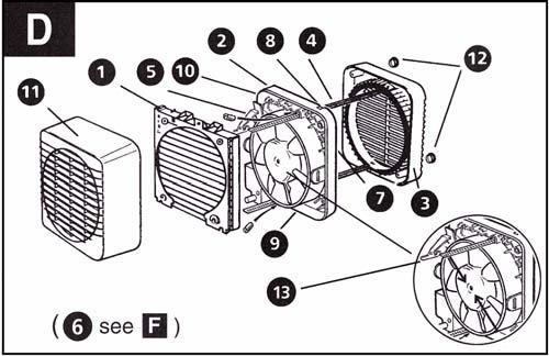
3 3. To remove the impeller, unscrew the central screw with a 7mm nut runner and remove it, place the screw to one side. 4. To clean the impeller, either wipe it with a damp, lint free cloth or wash it in warm soapy water. Do not use strong detergents or chemical cleaners.thoroughly dry the impeller and refit. Replace the screw ensuring that it is securely fitted. 5. Clean the back draught shutter and grille in warm soapy water. Do not use strong detergents or chemical cleaners. 6. Thoroughly dry the back draught shutter and grille and refit the back draught shutter to the grille by placing into position and pushing down until it clicks into position, see Fig. G3 and Fig. G4. 7. Refit the back draught shutter/grille assembly by sliding the grille back over the release catches, the catches will locate and secure the grille. Do not immerse the fan in water or other liquids to clean any other parts of the fan. Never use strong solvents to clean the fan. Apart from cleaning, no other maintenance is required. Components, Fig. D. 1. Back draught shutter. 2. Fan assembly. 3. Outer grille. 4. Ladder strips. 5. Terminal cover. 6. Trickle vent catch. 7. Rear cable entry. 8. Top cable entry. 9. Rating plate. 10. Lugs for screw mounting. 11. Grille. 12. Screw hole caps. 13. Actuator lever. Spares 40984SK Wax Actuator 41004SK Actuator Linkage Assy (GX6 EC2) 41010SK Outer Grille Assembly 41785SK Ladder Strip Kit SK Cord Actuator Assy (GXC6 EC2) 41904SK Impeller Assembly 41905SK Front Cover Assembly 41906SK GX6 EC2 Motor/Duct Assembly 41907SK GXC6 EC2 Motor/Duct Assembly
4
5 3. To remove the impeller, unscrew the central screw with a 7mm nut runner and remove it, place the screw to one side. 4. To clean the impeller, either wipe it with a damp, lint free cloth or wash it in warm soapy water. Do not use strong detergents or chemical cleaners.thoroughly dry the impeller and refit. Replace the screw ensuring that it is securely fitted. 5. Clean the back draught shutter and grille in warm soapy water. Do not use strong detergents or chemical cleaners. 6. Thoroughly dry the back draught shutter and grille and refit the back draught shutter to the grille by placing into position and pushing down until it clicks into position, see Fig. G3 and Fig. G4. 7. Refit the back draught shutter/grille assembly by sliding the grille back over the release catches, the catches will locate and secure the grille. Do not immerse the fan in water or other liquids to clean any other parts of the fan. Never use strong solvents to clean the fan. Apart from cleaning, no other maintenance is required. Components, Fig. D. 1. Back draught shutter. 2. Fan assembly. 3. Outer grille. 4. Ladder strips. 5. Terminal cover. 6. Trickle vent catch. 7. Rear cable entry. 8. Top cable entry. 9. Rating plate. 10. Lugs for screw mounting. 11. Grille. 12. Screw hole caps. 13. Actuator lever. Spares 40984SK Wax Actuator 41004SK Actuator Linkage Assy (GX6 EC2) 41010SK Outer Grille Assembly 41785SK Ladder Strip Kit SK Cord Actuator Assy (GXC6 EC2) 41904SK Impeller Assembly 41905SK Front Cover Assembly 41906SK GX6 EC2 Motor/Duct Assembly 41907SK GXC6 EC2 Motor/Duct Assembly
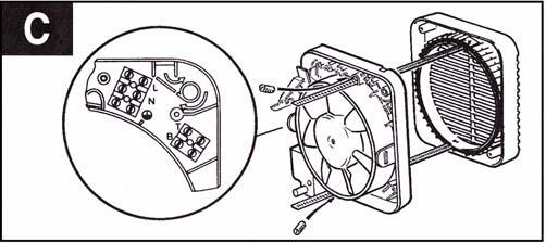
6 3. Drill the holes and insert anchor fixings to suit the wall. 4. Screw the outer grille securely in place. Do not over tighten screws. 5. Insert the two screw covers in the two fixing holes in the outer grille. 6a. If wiring from the rear, remove the fan s terminal cover and rear entry knockout. Feed the cable through the rear cable entry. 6b. If wiring from above, remove the fan s terminal cover and feed the cable through the top cable entry. 7. Hold the fan assembly to the inside of the wall so that the spigot is inserted into the wall duct. 8. Mark the position of the two fixing holes in the top left and bottom right corners. 9. Remove the fan assembly, drill the holes and insert anchor fixings appropriate to the type of wall. 10. Reposition the cable and fan assembly as before and screw securely in place. Do not over tighten screws. Note: For particularly difficult installations, it is possible to secure the fan with a combination of screw and ladder strip fixings. Wire the electrical connections 1. Wire the switch cable into the terminal connections as shown in: Fig. E1 for GX6 EC2 / GXC6 EC2 for single speed operation. Fig. E2 for GX6 EC2 / GXC6 EC2 for 2 speed selection operation using a change over switch (COS). 2. If the fan is wired from above, ensure the outer sheath of cable is retained in the labyrinth, see Fig. C. 3. Refit and secure terminal cover. 4. Refit the back draught shutter/grille assembly by sliding the grille back over the release catches, the catches will locate and secure the grille. 5. Switch off the mains electricity supply and remove fuses. 6. Connect the cable from the isolation switch to the electrical supply wiring. 7. Replace the fuses and switch on the mains electricity supply. For fixed wiring circuits the protective fuse for the appliances must not exceed 5A. Operating the fan These fans can either be single speed operation with a choice between High and Low at installation, or 2 speed operation when installed with a change over switch (COS). The shutters of the GX6 EC2 have a time delay of up to 1 minute on opening and up to 3 minutes on closing. Activated by operation of the switch, the delay ensures quiet operation. For Australia Only :- Warning Children should not play with the appliance. Young children and the infirm should be supervised. GX6 EC2 The fan is operated by a remote switch. Speed selection between High and Low is via a change over switch (COS) if installed. GXC6 EC2 The fan is operated by an integral pull cord. To switch on, pull down the cord and release it. Repeat to switch off. Speed selection between High and Low is via a change over switch (COS) if installed. Trickle ventilation Trickle ventilation is equivalent to that provided by an airbrick or similar device. 1. Remove the back draught shutter/grille assembly (see Mounting the fan in the hole section). To allow trickle ventilation 2. HOLD THE SHUTTER VANES FULLY OPEN. 3. Push down firmly on the trickle vent catch until it clicks into position then release the shutter vanes, see Fig. F. item 6. To fully close the shutters and stop any back draught 4. Pull the trickle vent catch towards you until it clicks into position. 5. Refit the back draught shutter/grille assembly, see Wire the electrical connections section, ensuring that the actuator lever is in the fully down position. Maintenance A QUALIFIED ELECTRICIAN MUST CARRY OUT ALL CLEANING. NOTE: THE FAN WILL CONTINUE TO OPERATE WITH THE INNER GRILLE REMOVED HENCE IT MUST BE ISOLATED COMPLETELY FROM THE MAINS BEFORE ANY WORK IS CARRIED OUT. 1. Before cleaning, isolate the fan completely from the mains electricity supply. On the GX6 EC2, allow 3 minutes for the impeller to stop rotating and the powered shutter to close. Cleaning on the GXC6 EC2 can begin once the impeller has stopped rotating. 2. Remove the back draught shutter/grille assembly by pressing the release catch located on the side of the unit with a 6mm screwdriver or a coin, whilst pulling the grille forward. To remove the back draught shutter, lay face down and pull the shutter forwards, see Fig. G1 and Fig. G2. 9
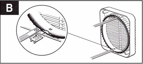
7 Installing the switches and cables 1. Check that there are no buried pipes or cables (eg. Electricity, gas, water) behind the switch location (in the wall or above the ceiling). 2. Lay in the cable from the isolating switch to the fan location via the on/off switch (see Fig. E1. For change over switch (COS) see Fig. E2. 3. Lay in the cable from the isolating switch to the point of connection to the mains supply. WARNING: DO NOT MAKE ANY CONNECTIONS TO THE ELECTRICITY SUPPLY AT THIS STAGE. 4. Install the isolating switch and the on/off switch, see Fig. E1. For change over switch (COS) see Fig. E2. 5. Make all connections within the isolating switch, on/off switch and change over switch (COS) if required. Note: When installed in a bathroom all switches must be of a pull cord type and must be situated so that they can not be touched by persons making use of the bath or shower. For Australia only Permanently connected to the supply and a remote switch operation. Wire directly to the supply through an approved 10A wall mounted surface switch with at least 3mm clearance between contacts. Preparing the hole If working above ground level, appropriate safety precautions must be observed. WARNING: EYE PROTECTION MUST BE WORN DURING ALL DRILLING AND CHISELLING OPERATIONS. If installing in a wall 1. Check there are no buried pipes or cables in a wall or obstructions on the outside (eg. Electricity, gas, water). 2. Ensure that the centre of the hole is located at least 145mm from the edges of the wall, see Fig. A. 3. Mark on the centre of the duct hole. 4. Use this centre to draw a circle to suit the wall duct (203mm diameter for a WK6/300 or WK6/450). If core drill equipment is available 5a. Use as directed by the core drill manufacturer. If core drill equipment is not available 5b. Drill a centre hole right through the wall. 6. Cut the hole. Do not cut right through the wall (the recommended method is to drill a series of holes, close together, around the edge of the cutting line and remove the brick between the holes with a chisel). 7. Go outside and cut a hole in the outer wall, repeating the process described above. 8. Fit the ducting. Ensuring that the duct slopes down away from the fan to allow drainage of any incoming rain water to the outside. 9. Make good the hole. Allow for the mortar to set before continuing with the installation. If installing in a window Obtain a ready cut pane with a correctly located hole 184mm diameter, see Fig. A. Preparing the fan for installation 1. For window mounting, use the two short ladder strips supplied with the fan. For wall mounting, use the longer ladder strips supplied with the wall kit WK6/300 or WK6/ Secure the two ladder strips to the outer grille by positioning them over the hook moulding and snapping them into position. 3. Ensure after fitting the hook moulding that the gasket is in the correct position, see Fig. B. 4. Insert the two screw covers in the two fixing holes in the outer grille. Mounting the fan in the hole, Fig. C. If working above ground level, appropriate safety precautions must be observed. Remove the back draught shutter/grille assembly by pressing the release catches located on the sides of the unit with a 6mm screwdriver or a coin, whilst pulling the grille forward. If installing with ladder strips 1. Hold up the outer grille to the outside wall or window so that the hole in the outer grille is aligned with the hole in the wall or window. 2a. If wiring from the rear, remove the fan s terminal cover and rear entry knockout. Feed the cable through the rear cable entry. 2b. If wiring from above, remove the fan s terminal cover and feed the cable through the top cable entry. 3. Hold the fan assembly to the inside of the wall or window and guide the ladder strips from the outer grille through the slots in the fan assembly. 4. Insert the slotted screws into the pockets around the ladder strip slots. 5. Tighten the screws carefully to make a good seal, do not over tighten the screws. 6. Trim the ladder strips back to the required length, if necessary remove any sharp edges. If using screw fixings 1. Hold the outer grille up to the outside of the wall so that the hole in the outer grille is aligned with the hole in the wall. 2. Mark the positions of the fixing holes in the top right and bottom left corners. 8
8
9
10 Xpelair Ultra GX6 EC2 & GXC6 EC2 Installation and Operating Instructions PLEASE LEAVE THIS LEAFLET WITH THE FAN, FOR THE BENEFIT OF THE USER. IMPORTANT 1. READ ALL THESE INSTRUCTIONS & WARNINGS FULLY BEFORE COMMENCING INSTALLATION. 2. INSTALLATIONS AND WIRING MUST CONFORM TO CURRENT IEE REGULATIONS (UK), LOCAL OR APPROPRIATE REGULATIONS (OTHER COUNTRIES). IT IS THE INSTALLER S RESPONSIBILITY TO ENSURE THAT THE APPROPRIATE BUILDING CODES OF PRACTICE ARE ADHERED TO. 3. A QUALIFIED ELECTRICIAN MUST SUPERVISE ALL INSTALLATIONS. 4. THESE APPLIANCES ARE INTENDED FOR CONNECTION TO FIXED WIRING. 5. CHECK THAT THE ELECTRICAL RATING SHOWN ON THE FAN MATCHES THE MAINS SUPPLY. 6. SITE THE FAN AWAY FROM DIRECT SOURCES OF HEAT (I.E. GAS COOKERS OR EYE LEVEL GRILLES. THE FAN MUST NOT BE MOUNTED WHERE AMBIENT TEMPERATURES ARE LIKELY TO EXCEED 50ºC. 7. WHEN THE FAN IS INSTALLED IN A ROOM CONTAINING A FUEL BURNING APPLIANCE, THE INSTALLER MUST ENSURE THAT AIR REPLACEMENT IS ADEQUATE FOR BOTH THE FAN AND THE FUEL BURNING APPLIANCE. 8. ENSURE THAT ALL RELEVANT SAFETY PRECAUTIONS (CORRECT EYE PROTECTION AND PROTECTIVE CLOTHING ETC) ARE TAKEN WHEN INSTALLING, OPERATING AND MAINTAINING THIS FAN. 9. ALWAYS LOCATE THE FAN AS HIGH AS POSSIBLE. AT LEAST 145mm FROM THE EDGE OF THE WALL/WINDOW FRAME TO THE HOLE CENTRE (SEE FIG. A). LOCATE THE FAN AS FAR AS POSSIBLE FROM AND OPPOSITE TO THE MAIN SOURCE OF AIR REPLACEMENT TO ENSURE AIRFLOW ACROSS THE ROOM (eg. OPPOSITE AN INTERNAL DOORWAY). 10. THIS ELECTRICAL PRODUCT, IF INSTALLED IN A SHOWER ROOM OR BATHROOM, MUST BE SITUATED SO THAT IT CAN NOT BE TOUCHED BY PERSONS MAKING USE OF THE BATH OR SHOWER. 11. WHEN INTENDED FOR USE IN POSSIBLE CHEMICAL CORROSIVE ATMOSPHERES, CONSULT OUR TECHNICAL SERVICE DEPARTMENT. (FOR OVERSEAS MARKETS CONTACT YOUR LOCAL XPELAIR DISTRIBUTOR). 12. THIS APPLIANCE IS NOT INTENDED FOR USE BY PERSONS (INCLUDING CHILDREN) WITH REDUCED PHYSICAL, SENSORY OR MENTAL CAPABILITIES, OR LACK OF EXPERIENCE AND KNOWLEDGE, UNLESS THEY HAVE BEEN GIVEN SUPERVISION OR INSTRUCTION CONCERNING USE OF THE APPLIANCE BY A PERSON RESPONSIBLE FOR THEIR SAFETY. CHILDREN SHOULD BE SUPERVISED TO ENSURE THAT THEY DO NOT PLAY WITH THE APPLIANCE. Description The Ultra GX6 models have the following features: Window / Wall / Panel / Roof mounting options. GX6 EC2 For remote switch operation. 2 speed operation when installed with a change over switch (COS) not supplied, see Fig. E2. Single speed operation with a choice of High or Low speed selectable at installation. Trickle ventilation setting. GXC6 EC2 Integral pull cord operation. 2 speed operation when installed with a change over switch (COS) not supplied, see Fig. E2. Single speed operation with a choice of High or Low speed selectable at installation. Trickle ventilation setting. What the installer will need A means of disconnection in all poles must be provided in the fixed wiring in accordance with the wiring rules. If metal switch boxes are used, earthing regulations must be followed. Suitably rated 4-core cable (not including green/yellow as earthing of the product is not required) when installing with a change over switch (COS) for 2 speed selection. Suitably rated 2-core cable for single speed operation, and a link wire if required to select Low speed. A change over switch (COS), if required, (available from Xpelair). 6mm blade large screwdriver, 3mm blade electrician s screwdriver and No. 1 and 2 Pozidriv screwdrivers. 7mm nut runner (for removing the impeller when cleaning). If window mounting the fan, you will also need: A single glazed window with a minimum glass thickness of 4mm or a double glazed unit with a pre-prepared sealed hole. If wall mounting the fan, you will also need: Masonry drill, hammer and chisel (or core drill equipment, if available). Mortar (to make good the hole). Wall kit WK6/300 (available from Xpelair) for walls up to 300mm (12 ) thick or WK6/450 (available from Xpelair) for walls up to 450mm (18 ) thick. 4 mounting fasteners (use fasteners suitable for wall type. Recommended screw size for standard brick No. 8 x 38mm Pan Head). 7
11 GUARANTEE Terms and Conditions for UK & ROI (outside UK & ROI contact your local distributor) We, Applied Energy Products Limited, guarantee this product for residential use only, for the period of 5 years from the date of purchase subject to the following conditions initial 3 years parts and labour, final 2 years parts only. Within the guarantee period we will resolve, free of charge, any manufacturing defects in the product resulting from faulty workmanship or material on condition that:- a) The appliance has been correctly installed in accordance with our instructions and is being used on the supply circuit or voltage printed on the rating plate. b) The appliance has been used in accordance with these instructions and has not been tampered with or otherwise subject to misuse, neglect or accident. c) The appliance has been regularly maintained in accordance with these instructions and the airway is unobstructed. d) The appliance has not been taken apart, modified or repaired except by a person authorised by us. e) Evidence of the date of purchase in the form of an invoice or receipt will be required in order to qualify under the terms of this guarantee. f) For the service work to be undertaken free of charge, the work must only be undertaken by Applied Energy Products Limited, or our approved agents. g) Service under guarantee has no effect on the expiry date. The guarantee on any exchanged parts or product ends when the original guarantee period ends. h) In the event of a product being returned to Applied Energy Products Limited and not found to be faulty, the product would be available for collection from the relevant premises within one month and if not collected it would be disposed of or delivered by Applied Energy Products Limited and a delivery charge made. EXCLUSIONS This guarantee DOES NOT cover damage or defects arising from poor or incorrect installation, improper use or lack of maintenance. It is the responsibilty of the installer to check that the installation parameters meet the requirements of the product, and any relevant regulations. If we are called out to a fault, which is subsequently identified as being an installation fault, we will make a charge. It is important that the routine checks are completed before calling us out, as many issues can be simply diagnosed and resolved. We make no guarantees as to response times for repairs. We will endeavour to achieve the most timely response possible but while we indicate an average response time, this should not be taken as a guarantee. The guarantee applies to a repair or replacement (at our discretion) of the product subject to the conditions above, and DOES NOT cover compensation for the loss of the product or consequential loss of any kind. This guarantee does not affect your statutory rights. Applied Energy Products Ltd Morley Way Peterborough PE2 9JJ Tel: +44 (0) Fax: +44 (0) Sales Hotline: +44 (0) For Technical Advice (Techline) Tel: +44 (0) Fax: +44 (0) For Spares Requirements (UK Only) Tel: +44 (0) Fax: +44 (0) Xpelair is a registered trademark of Applied Energy Products Limited. Applied Energy Products reserve the right to alter product specifications or appearance without prior notice. All finishes and diagrams in this booklet are as accurate as printing processes allow. A4 Leaflet Number: 23161AA Revision A
Internal/External Wall/Window Fan Range GX6. Installation and maintenance instructions Retain for future use
 Internal/External Wall/Window Fan Range GX6 Installation and maintenance instructions Retain for future use A GLASS WINDOW B C D ( 6 see F ) 13 E1 E2 E3 G1 G2 G3 G4 H I GB Xpelair GX6, GXC6, GXC6T, GX6HT
irconcentre.co.uk airooncentre.co.uk
 Installation and maintenance instructions DX100 Standard DX100PC Pull Cord DX100T Timer DX100H Humidistat DX100HP Humidistat and Pull Cord DX100PIR Integral Body Movement Sensor DX100VTD Delay Timer Toilet/Bathroom
LV100 Standard LV100PC Pull Cord LV100T Timer LV100H Humidistat LV100HP Humidistat and Pull Cord LV100PIR
 Installation and operating instructions LV100 Standard LV100PC Pull Cord LV100T Timer LV100H Humidistat LV100HP Humidistat and Pull Cord Safety extra low voltage toilet/bathroom 100mm fan range Integral
Xpelair Simply Silent TM Contour Fan
 Xpelair Simply Silent TM Contour Fan Installation and Maintenance Instructions C4S (92960AW) / C4R (92961AW) C4TS (92962AW) / C4TR (92963AW) C4PS (92964AW) / C4PR (92965AW) C4HTS (92966AW) / C4HTR (92967AW)
Xpelair Simply Silent DX150
 English Xpelair Simply Silent DX150 Installation and Maintenance Instructions DX150S (93070AW) DX150R (93071AW) DX150TS (93072AW) DX150TR (93073AW) DX150PS (93074AW) DX150PR (93075AW) DX150HTS (93076AW)
Simply Silent Contour 4 (100mm) Axial Extraction Fan
 Axial Extraction Fan") Simply Silent Contour 4 (100mm) Axial Extraction Fan Suitable for bathrooms, toilets, shower and utility rooms Controls humidity, odours and mould growth Sleek low-profile design, wall or ceiling mounting
Simply Silent Contour 4 (100mm) Axial Extraction Fan Suitable for bathrooms, toilets, shower and utility rooms Controls humidity, odours and mould growth Sleek low-profile design, wall or ceiling mounting
Xpelair Simply Silent TM DX100 Fan
 Xpelair Simply Silent TM DX100 Fan Installation and Maintenance Instructions DX100R (93005AW) / DX100S (93025AW) DX100TR (93006AW) / DX100TS (93026AW) DX100PR (93007AW) / DX100PS (93027AW) DX100HTR (93008AW)
Xpelair Simply Silent DX100
 Xpelair Simply Silent DX100 English Nederlands Installation n and Maintenance Instructions Installa en Onderho ru DX100R (93005AW) DX100S (93025AW) DX100TR (93006AW) DX100TS (93026AW) DX100HPTR (93009AW)
Xpelair Simply Silent DX100B
 Xpelair Simply Silent DX100B Installation and Maintenance Instructions English DX100BR (92997AW) DX100BS (93017AW) DX100BTR (92998AW) DX100BTS (93018AW) DX100BHTR (92999AW) DX100BHTS (93019AW) DX100BHPTR
BOILING UNIT REDITAP. Installation and User Guide. IMPORTANT: This booklet should be left with the user after installation and demonstration
 in tap Boiling water to in tap sink Drain Valve (as high as possible) REDITAP CONNECTION SUMMARY Amp mains supply cold mains water into in tap optional filter cold water in hot water BOILING UNIT Installation
Lo-Carbon T-series Window & Roof Models
 Lo-Carbon T-series Window & Roof Models Installation & User Instructions WIRED 456165A (9 WW) 456168A (9 RF) 456173A (12 WW) 456176A (12 RF) WIRELESS 456169A (9 WW) 456172A (9 RF) 456177A (12 WW) 456180A
THE BOILING WATER DISPENSER INSTALLATION & OPERATING INSTRUCTIONS IMPORTANT: READ AND SAVE THESE INSTRUCTIONS FOR THE BENEFIT OF THE USER
 THE BOILING WATER DISPENSER INSTALLATION & OPERATING INSTRUCTIONS IMPORTANT: READ AND SAVE THESE INSTRUCTIONS FOR THE BENEFIT OF THE USER Thank you for choosing a quality Redring product manufactured by
T-SERIES. Window & Roof Models. Installation, Set-up and Operating Instructions. 230V/1/50Hz
 T-SERIES Window & Roof Models Installation, Set-up and Operating Instructions Stock Ref. Nos. WIRED 456165A (9" WW) 456168A (9" RF) 456173A (12" WW) 456176A (12" RF) WIRELESS 456169A (9" WW) 456172A (9"
Xcell 270 Longlife DC wholehouse heat recovery unit
 Xcell 270 Longlife DC wholehouse heat recovery unit Installation and maintenance instructions Xpelair Xcell 270 Longlife DC wholehouse heat recovery unit Xcell 270, Xcell 270BP Please leave this leaflet
PLEASE READ INSTRUCTIONS IN CONJUNCTION WITH ILLUSTRATIONS. PLEASE SAVE THESE INSTRUCTIONS.
 Eclipse Installation and Wiring Instructions Models Eclipse 100X Eclipse 100XP Eclipse 100XT Eclipse 150X Eclipse 150XP Ref No. 42 73 10A 42 72 81A 42 72 82A 42 72 83A 42 73 13A 220-240V~50Hz PLEASE READ
REDRING POWERSTREAM UNVENTED INSTANTANEOUS WATER HEATER. Installation and User Guide
 REDRING POWERSTREAM UNVENTED INSTANTANEOUS WATER HEATER Installation and User Guide IMPORTANT: This booklet should be left with the user after installation and demonstration. It should be kept in a safe
T-SERIES. Wall & Panel Models. Installation, Set-up and Operating Instructions. 230V/1/50Hz
 T-SERIES Wall & Panel Models Installation, Set-up and Operating Instructions Stock Ref. Nos. WIRED 456166A (9" WL) 456167A (9" PL) 456174A (12" WL) 456175A (12" PL) WIRELESS 456170A (9" WL) 456171A (9"
Vent-Axia Svara Multifunctional app controlled fan. Important Information 2 Installation and Wiring Instructions 3-11 Accessories 12 Pin Code 12
 Vent-Axia Svara Multifunctional app controlled fan Important Information 2 Installation and Wiring Instructions 3- Accessories 2 Pin Code 2 6 2 Ø99 Ø77 Important: READ THESE INSTRUCTIONS BEFORE COMMENCING
VA 150 A, VA 150 P WINDOW EXTRACT FAN. Installation and Wiring Instructions V/1/50Hz
 VA 150 A, VA 150 P WINDOW EXTRACT FAN Installation and Wiring Instructions VA150 P STOCK Ref: 152110B VA150 A STOCK Ref: 153110B 220-240V/1/50Hz READ INSTRUCTIONS IN CONJUNCTION WITH ILLUSTRATIONS PLEASE
Lo-Carbon Quadra Centrifugal Fan
 Lo-Carbon Quadra Centrifugal Fan Installation and Wiring Instructions Stock Ref. N Quadra TP Quadra TM Quadra HTP 439251A 439253A 439181A 220-240V~50Hz IPX4 PLEASE READ INSTRUCTIONS IN CONJUNCTION WITH
Lo-Carbon SELV Tempra
 Lo-Carbon SELV Tempra THROUGH THE WALL HEAT RECOVERY FAN Installation and Wiring Instructions DRAFT Stock Ref. N 444368 Pullcord. (SVP) 444369 Timer. (SVT) 444370 Humidistat -Timer Pullcord. (SVHTP) 220-240V~50Hz
Lo-Carbon Quadra SELV
 Lo-Carbon Quadra SELV Installation and Wiring Instructions Stock Ref. N Quadra SVTP 442865 Quadra SVHTP 442866 Quadra SVTM 442867 Safety Extra Low Voltage IPX7 PLEASE READ INSTRUCTIONS IN CONJUNCTION WITH
60cm Chimney Extractor
 60cm Chimney Extractor LAM2401 HJA2480 User & Installation Guide Contents Page Environmental note 3 IMPORTANT SAFETY INFORMATION 4 6 Specifications of your extractor 7 8 Dimensions 7 Specifications 7-8
BWT6.3GL Cooker Hood 60 cm Glass chimney hood
 User Manual for your BWT6.3GL Cooker Hood 60 cm Glass chimney hood NOTE: This User Instruction Manual contains important information, including safety & installation points, which will enable you to get
Lucci Designer Hi Flow Exhaust Fan
 USE AND CARE INSTRUCTION INSTALLATION INSTRUCTION Lucci Designer Hi Flow Exhaust Fan SKU# 200265&200267 MXSQ8PW(200mm) SKU# 200266&200268 MXSQ10PW(250mm) Dear Customers, Thank you for selecting a LUCCI
Centrif Duo & Centrif Duo Plus
 Centrif Duo & Centrif Duo Plus Installation and Wiring Instructions Stock Ref. N Centrif Duo P 25 61 20D Centrif Duo T 25 62 20D Centrif Duo DP 25 63 20D Centrif Duo HTP 25 64 20D Centrif Duo Centrif Duo
GUH90 90 cm Canopy Hood
 User Manual for your GUH90 90 cm Canopy Hood NOTE: This User Instruction Manual contains important information, including safety & installation points, which will enable you to get the most out of your
BWTC6510GL Cooker Hood 60 cm Glass cooker hood in stainless steel. BWTC9510GL Cooker Hood 90 cm Glass cooker hood in stainless steel
 User Manual for your BWTC6510GL Cooker Hood 60 cm Glass cooker hood in stainless steel BWTC9510GL Cooker Hood 90 cm Glass cooker hood in stainless steel NOTE: This User Instruction Manual contains important
PLEASE READ INSTRUCTIONS IN CONJUNCTION WITH ILLUSTRATIONS.
 Silhouette Installation and Wiring Instructions Stock Ref. N 45 40 55B (100B) 44 51 61 (125B) 45 40 59B (150X) 45 40 56B (100T) 44 51 62 (125T) 45 40 60B (150XT) 45 40 57B (100HT) 44 51 63 (125HT) 45 40
SHOWER HANDBOOK IMPORTANT
 SHOWER HANDBOOK IMPORTANT This booklet should be given to the customer after installation and demonstration. Thank you for choosing a quality Redring product manufactured in Peterborough, England. Contents
850DL & 950DL CREDA 850DL & 950DL ELECTRIC SHOWER. Installation and User Guide
 850DL & 950DL CREDA 850DL & 950DL ELECTRIC SHOWER Installation and User Guide IMPORTANT: This booklet should be left with the user after installation and demonstration CONTENTS Section Introduction...........................................................
DC Heat Recovery Unit MVHR Wholehouse heat recovery unit
 DC Heat Recovery Unit MVHR Wholehouse heat recovery unit Stock Ref. N DC Heat Recovery Unit MVHR 443423 Installation, Maintenance & Users Instructions PLEASE READ INSTRUCTIONS IN CONJUNCTION WITH ILLUSTRATIONS.
BT16.4SS-HK BT19.4SS-HK Cooker Hood
 BT16.4SS-HK BT19.4SS-HK Cooker Hood User Manual for your Baumatic User Manual for your Baumatic BT16.4SS-HK 60 cm Chimney Hood BT19.4SS-HK 90 cm Chimney Hood NOTE: This User Instruction Manual contains
Manual and Thermostatic Power Shower Units
 520M/520TS Manual and Thermostatic Power Shower Units Installation instructions & User guide IMPORTANT: This booklet should be given to the customer after installation and demonstration. WARNING: Under
Installation and User Guide Please leave this guide with the end user (for future reference)
") Contact and Commissioning Details Installer Contact Name and Address : Model N : Serial N : Date Installed : Installation and User Guide Please leave this guide with the end user (for future reference)
Contact and Commissioning Details Installer Contact Name and Address : Model N : Serial N : Date Installed : Installation and User Guide Please leave this guide with the end user (for future reference)
01 Safety. IMPORTANT Be sure to have read and understood these instructions before beginning the installation process.
 01 Safety IMPORTANT Be sure to have read and understood these instructions before beginning the installation process. This fan can be wall, ceiling, inline or window mounted You must ensure that any emissions
IXL Eco Ventflo. User Guide. Model: (200mm) - Extraction Rate: 340m 3 /h Model: (250mm) - Extraction Rate: 490m 3 /h
 - Extraction Rate: 340m 3 /h Model: (250mm) - Extraction Rate: 490m 3 /h") User Guide Model: 10324 (200mm) - Extraction Rate: 340m 3 /h Model: 10326 (250mm) - Extraction Rate: 490m 3 /h Electrical Rating: 230~240 V. 50 Hz. Welcome Safety Thank you for buying this Fan. Even if
User Guide Model: 10324 (200mm) - Extraction Rate: 340m 3 /h Model: 10326 (250mm) - Extraction Rate: 490m 3 /h Electrical Rating: 230~240 V. 50 Hz. Welcome Safety Thank you for buying this Fan. Even if
November This product has been reconfigured Please read these instructions
 November 2013 This product has been reconfigured Please read these instructions Contents Page 01 Introduction 2 02 Box Contents 3-4 03 Tools Checklist 5 03A Pre-Installation Checklist 6 04 Controls 6 05
GUH52SD 52 cm GUH75 75 cm Canopy Hood
 User Manual for your GUH52SD 52 cm GUH75 75 cm Canopy Hood NOTE: This User Instruction Manual contains important information, including safety & installation points, which will enable you to get the most
GEH9026G Cooker Hood
 User Manual for your GEH9026G Cooker Hood 90 cm Chimney Hood in Stainless Steel NOTE: This User Instruction Manual contains important information, including safety & installation points, which will enable
EKF. EC kitchen extract fan range. Installation and Wiring Instructions. Stock Ref. N EKF355E1 EKF400E1 EKF450E1 EKF450E3 EKF500E3 EKF560E3
 EKF EC kitchen extract fan range Installation and Wiring Instructions Stock Ref. N EKF355E1 EKF400E1 EKF450E1 EKF450E3 EKF500E3 EKF560E3 PLEASE READ INSTRUCTIONS IN CONJUNCTION WITH THE ILLUSTRATIONS.
BLOW DRY & GO HAIR KIT
 BLOW DRY & GO HAIR KIT LSGS11P Instruction Manual My BLow DRy and go HAiR KiT is perfect with everything you need to style your hair the way you want - wherever you are. This kit includes accessories for
Thank you for choosing EnviroVent
 Contents 01 Introduction 2 02 Technical Specification 3-4 03 Wiring Diagrams 5-6 04 Safety 7-8 05 Controls 8 06 Box Contents 9 07 Tools Checklist 10 08 Installation Steps 11 09 Installation 12-22 10 RF
WHHR Midi & Midi Lite
 WHHR Midi & Midi Lite Residential Whole House Heat Recovery Units with Low Energy EC Motors Optional - Integral LCD Installation, Operating and Maintenance Instructions Image of model with LCD screen Page
kW kW kW kW
 TEMPESTA 100 ELECTRIC SHOWER DESIGN + ENGINEERING GROHE GERMANY 99.0351.031/ÄM 231959/08.14 www.grohe.com 26 178 8.5kW 26 179 9.5kW 26 221 9.5kW 26 222 9.5kW IMPORTANT: This booklet should be left with
EXTRACTOR HOOD. Please read all the instructions carefully before starting the installation. 230 / 240V 50Hz
 abc EXTRACTOR HOOD Please read all the instructions carefully before starting the installation Model Stock Ref Napoli 120812 Napoli Plus (white) 436083 Napoli Plus (Silver) 436084 230 / 240V 50Hz PLEASE
SP16. 08/50740/1 (UK) - Issue 1
 - Issue 1") SP16 08/50740/1 (UK) - Issue 1 The product complies with the European Safety Standards EN60335-2-30 and the European Standard Electromagnetic Compatibility (EMC) EN55014, EN60555-2 and EN60555-3 These
SP16 08/50740/1 (UK) - Issue 1 The product complies with the European Safety Standards EN60335-2-30 and the European Standard Electromagnetic Compatibility (EMC) EN55014, EN60555-2 and EN60555-3 These
HOTLINE:
 You are about to install a product that is designed to outlast the life-cycle of the building. Once installed the unit will operate continuously for 5 years and beyond without a major service. Please therefore
CREDA FLORIDA PLUS ELECTRIC SHOWER. Installation and User Guide
 CREDA FLORIDA PLUS ELECTRIC SHOWER Installation and User Guide IMPORTANT: This booklet should be left with the user after installation and demonstration THIS APPLIANCE CAN BE USED BY CHILDREN AGED FROM
Installation & Operating Instructions
 Installation & Operating Instructions For 4 / 100mm Centrifugal s Models: K612 & K612T Thank you for purchasing a quality Centrifugal from GreenBrook. Please read these instructions fully prior to initial
MEV SPIDER INSTALLATION GUIDE FOR ENGINEER / INSTALLER
 MEV SPIDER INSTALLATION GUIDE FOR ENGINEER / INSTALLER Safety IMPORTANT Be sure to have read and understood these instructions before beginning the installation process. PRE-INSTALLATION CHECK LIST Make
PLEASE READ INSTRUCTIONS IN CONJUNCTION WITH ILLUSTRATIONS.
 Silhouette Lo-Carbon RANGE 100/150mm AXIAL EXTRACT FAN Installation and Wiring Instructions Stock Ref. N 44 16 24-100B 44 16 25-100T 44 16 26-100HT 44 16 28-150B 44 16 29-150T 44 16 30-150HT 220-240V~50Hz
60cm Integrated Turbo Extractor
 60cm Integrated Turbo Extractor LAM2201 User & Installation Guide Dear Customer, Congratulations on your choice of domestic appliance which has been designed to give you excellent service. The user manual
HS&S Alert No: 103 Date: 9 March 2017
 HS&S Alert No: 103 Date: 9 March 2017 RECENT CABIN FIRES WALL MOUNTED DOWN FLOW HEATER UNITS This is an update to Alert No 83, following a further cabin fire involving a wall mounted downflow heater unit.
I n s t r u c t i o n m a n u a l f o r b u i l t - i n h o o d. Model code: BORA600
 I n s t r u c t i o n m a n u a l f o r b u i l t - i n h o o d Model code: BORA600 Contact Caple on 0844 8003830 or for spare parts www.4caple.co.uk 1 Y O U R A P P L I A N C E Thank you for buying your
INSTANTANEOUS ELECTRIC SHOWER
 GUARANTEE / SERVICE POLICY INSTANTANEOUS ELECTRIC SHOWER GUARANTEE Designa guarantee this DS3000 product for a period of two years, from date of purchase, against mechanical and electrical defects arising
IF IN DOUBT, INSTALLATION SHOULD BE MADE BY A QUALIFIED ELECTRICIAN IN ACCORDANCE WITH CURRENT WIRING REGULATIONS.
 INSTALLATION/OPERATING INSTRUCTIONS FOR C100 & C100T Thank you for purchasing a quality Extractor fan from Greenbrook. Please read these instructions fully prior to initial use. Every effort has been made
Installation Instructions & Operating Manual IMPORTANT
 Installation Instructions & Operating Manual IMPORTANT These instructions should be read carefully and retained for future reference TABLE OF CONTENTS SECTION 1: WARNINGS & ELECTRIC SPECIFICATIONS 1.1
TEMPAIR 3 IN 1 EXHAUST FAN SKU# &
 TEMPAIR 3 IN 1 EXHAUST FAN SKU# 200290 & 200291 CAUTION READ INSTRUCTIONS CAREFULLY FOR SAFE INSTALLATION AND FAN OPERATION. WARRANTY - This product is covered by a 3 year warranty. The warranty is from
isense & isense-ht 230V Flush Mounted Domestic Continuous Extract Fans
 isense & isense-ht 230V Flush Mounted Domestic Continuous Extract Fans Installation and Maintenance IPX4* The EMC Directive 2014/30/EU The Low Voltage Directive 2014/35/EU 1.0 SAFETY INFORMATI The installation
Contact Details. Please note that some of the contact details on this PDF document may not be current.
 Contact Details Please note that some of the contact details on this PDF document may not be current. Please use the following details if you need to contact us: Telephone: 0844 879 3588 Email: customer.services@gdcgroup.co.uk
NV3610N NV7210N NV9610N.
 www.blackanddecker.co.uk NV3610N NV7210N NV9610N A B C 2 D E F 3 Intended use Your BLACK+DECKER TM Dustbuster handheld vacuum cleaner has been designed for light dry vacuum cleaning purposes. This appliance
Instruction manual. Please keep safe for future reference
 16in / 40cm Eco Pedestal Fan with 30W DC motor, Digital Display & Remote Control Model: SFDC-40101RC WARNING: Keep Batteries Out of Reach of Children 1. Swallowing may lead to serious injury in as little
IMPORTANT- RETAIN FOR FUTURE REFERENCE CALL:
 GENOA WALL FIREPLACE Assembly instructions Actual product size H56 x W96 x D4cm Need Help? With: Assembly instructions Missing or damaged parts IMPORTANT- RETAIN FOR FUTURE REFERENCE CALL: 0333 777 8999
Installation and Operating Instructions. Models: T4-13DM-SLI-1 T4-14DM-LOW-1 T4-15DM-CUR-1 T4-18GBOX
 Installation and Operating Instructions Models: T4-13DM-SLI-1 T4-14DM-LOW-1 T4-15DM-CUR-1 T4-18GBOX As part of Parmco Appliances commitment to improving and upda ng product ranges, we reserve the right
Wiring the fan correctly...
 You are about to install a product that is designed to outlast the life-cycle of the building. Once installed the unit will operate continuously for 7 years and beyond without a major service. Please therefore
200W Frostwatch Radiant Heater Operation Manual
 LEVFW200 200W Frostwatch Radiant Heater Operation Manual REMOVE ALL PACKAGING MATERIALS FROM THIS PRODUCT BEFORE USING IT LEVFW200 200W Frostwatch Radiant Heater IMPORTANT: Read these instructions fully
FAITH (dmev) 230V / 24V DC SELV Flush Mounted Domestic Continuous Extract Fans
 230V / 24V DC SELV Flush Mounted Domestic Continuous Extract Fans") FAITH (dmev) 230V / 24V DC SELV Flush Mounted Domestic Continuous Extract Fans Installation and Maintenance IPX4* The EMC Directive 2014/30/EU The Low Voltage Directive 2014/35/EU 1.0 SAFETY INFORMATION
FAITH (dmev) 230V / 24V DC SELV Flush Mounted Domestic Continuous Extract Fans Installation and Maintenance IPX4* The EMC Directive 2014/30/EU The Low Voltage Directive 2014/35/EU 1.0 SAFETY INFORMATION
HR200WK Through the wall Heat Recovery Ventilator
 HR200WK Through the wall Heat Recovery Ventilator Installation and Maintenance Instructions Stock Ref No:- HR200WK 14120020 PLEASE READ INSTRUCTIONS IN CONJUNCTION WITH ILLUSTRATIONS. PLEASE SAVE THESE
Installation and User Instructions Aquarius Undersink Vented Water Heaters Models: AU7/3, AU7/1, AU10/3, AU10/1.
 Installation and User Instructions Aquarius Undersink Vented Water Heaters Models: AU7/3, AU7/1, AU10/3, AU10/1. Please read and understand these instructions before starting work. Please leave this leaflet
Installation & User Instructions: Model: Arizona/Broadway/Corsano/Compton/Compton1000/Corbiere/Empire /Newark/Newark1000/Qube/Tribeca
 Installation & User Instructions: Model: Arizona/Broadway/Corsano/Compton/Compton1000/Corbiere/Empire /Newark/Newark1000/Qube/Tribeca Once installed, the installer should take the appropriate steps To
Models: RP-10, RP-15, RP-20. User Manual
 Models: RP-10, RP-15, RP-20 User Manual Contents Thank you for purchasing the Ducasa Sunburst Radiant Panel Heater. Index Safety Precautions & Important Safeguards:... 3 Specifications:... 5 Features...
nergybulbs.co.uk Domestic AC Fans 230V Installation and Operating Guide Quick Order Hotline or
 Domestic AC Fans 230V Installation and Operating Guide 230V AC Base Models: ico15 72683501 ico15c 72591501 ico30 72591601 ico60 72591701 ico Domestic Fan 230V Installation, Maintenance and Use ico Domestic
CoCo LoCo BLOW & GO NUTS DRYER. LSHD24 Instruction Manual
 CoCo LoCo BLOW & GO NUTS DRYER LSHD24 Instruction Manual This GORGeous PiNK and rose gold dryer is infused with coconut oil to give your hair a boost when it s driving you nuts. With a powerful 2400W motor
Optimax Refrigerated Retail Merchandisers
 V Optimax Refrigerated Retail Merchandisers MODEL NUMBERS RMR65E/SMR65ECT RMR100E/SMR100ECT RMR130E/SMR130ECT RMR65S RMR100S RMR130S RMR65SW RMR100SW RMR130SW RMR65SP RMR100SP RMR130SP Assisted service
INTEGRA PLUS ABC. 230V~ 50Hz. Stock Ref. N. Installation and Wiring Instructions IPX2
 INTEGRA PLUS Installation and Wiring Instructions Stock Ref. N INTEGRA PLUS 437666 230V~ 50Hz ABC PLEASE READ INSTRUCTIONS IN CONJUNCTION WITH ILLUSTRATIONS. PLEASE SAVE THESE INSTRUCTIONS. IPX2 VENT-AXIA
Verdi 90 & 120 Ceiling Hood Re-Circulating and Ducted Installation & User Instructions
 Verdi 90 & 120 Ceiling Hood Re-Circulating and Ducted Installation & User Instructions Please read these instructions carefully before installing and operating this appliance 1 Contents 1. Introduction
LUCCI AIRFUSION SHOALHAVEN CEILING FAN
 LUCCI AIRFUSION SHOALHAVEN CEILING FAN INSTALLATION OPERATION MAINTENANCE WARRANTY INFORMATION CAUTION READ INSTRUCTIONS CAREFULLY FOR SAFE INSTALLATION AND FAN OPERATION. V1.0 EN -WS ( 08/2018 ) THANK
Installation & User Instructions: Model: e600s e600gf e700s e1000s e1000gf e1030gf/2/3 e1500gf/2/3
 Installation & User Instructions: Model: e600s e600gf e700s e1000s e1000gf e1030gf/2/3 e1500gf/2/3 Once installed, the installer should take the appropriate steps To ensure that the user understands how
Wiring the fan correctly...
 You are about to install a product that is designed to outlast the life-cycle of the building. Once installed the unit will operate continuously for 7 years and beyond without a major service. Please therefore
EH kW Panel Heater
 EH1390 1.5kW Panel Heater Adjustable thermostat 24 hour timer Wall mounting or free-standing Silent operation Stylish, slim design Safety overload cut-out 2 year guarantee Page 1 IMPORTANT Installer and
2.9kW Portable Air Conditioner
 Operating Instructions 2.9kW Portable Air Conditioner Item: GCPAC210 General Care and Safety Guide Thank you for choosing this Goldair product. This Goldair appliance has been designed and manufactured
Operating and installation instructions
 Operating and installation instructions Plate warming drawer EGW 3060-10 To avoid the risk of accidents or en-gb damage to the appliance it is essential to read these instructions before it is installed
Lo-Carbon Quadra Centrifugal Fan
 Lo-Carbon Quadra Centrifugal Fan Installation and Wiring Instructions Stock Ref. N Quadra TP Quadra TM Quadra HTP 439251A 439253A 439181A 220-240V~50Hz IPX4 PLEASE READ INSTRUCTIONS IN CONJUNCTION WITH
Australia. New Zealand
 .... Australia New Zealand 2 5 3 4 JA JB JC JD JE JF JG JH JI JJ JK JL JM JN JO 5 Intended use Your Black & Decker vacuum cleaner has been designed to vacuum dry substances. This product is intended for
BFR6 / BFR9 Rangehood
 BFR6 / BFR9 Rangehood User Manual for your Baumatic BFR6, 60 cm Rangehood BFR9, 90 cm Rangehood NOTE: This User Instruction Manual contains important information, including safety & installation points,
Instruction Manual JLHDA cm Cooker hood
 Contents 3 Introduction 3 Safety is important 3 In the box 4 Safety information 4 Important safety information 4 Warnings 5 Cautions 5 Electrical information 6 Remote control 6 Programming the remote control
Installation & Operating Instructions
 Installation & Operating Instructions For 12V Extractor s Models: (4 ) G510SELV, (6 ) G242SELV For 12V Controllers Models: 12VFC, 12VFCT & 12VFCHS Thank you for purchasing a quality 12V Extractor & Controller
Installation instructions. and User guide. Designer wall glass canopy NZ AU. HC90CGX1 & HC60CGX1 models
 Designer wall glass canopy HC90CGX1 & HC60CGX1 models Installation instructions and User guide NZ AU Installation instructions 1 1 2 3 4 2 Installation instructions Warning! Failure to install the screws
Girona. Operating Instructions. Glass Panel Heaters. Models: GFP050 W/B GFP075 W/B GFP100 W/B GFP150 W/B GFP200 W/B. A world of expertise
 A world of expertise Operating Instructions These instructions should be read carefully and retained for future use. Note also the information presented on the appliance. Girona Glass Panel Heaters Models:
User Instructions for Remote Controlled 2kW Rotisserie Effect Fan Heater Model 1276
 200662_2 Page 1 User Instructions for Remote Controlled 2kW Rotisserie Effect Fan Heater Model 1276 These instructions should be read carefully and retained for future reference. Important Notes These
PLEASE READ INSTRUCTIONS IN CONJUNCTION WITH ILLUSTRATIONS.
 VA100 Lo-Carbon RANGE 100mm AXIAL EXTRACT FAN Installation and Wiring Instructions Stock Ref. N 44 31 59 - LP 44 31 60 - XP 44 31 61 - LT 44 31 62 - XT 44 31 63 - LHTP 44 31 64 - XHTP 220-240V~50Hz PLEASE
Academy The Straightener IM.indd 1 24/06/ :10. Instruction Manual LSHS16
 Academy The Straightener IM.indd 1 24/06/2016 11:10 Instruction Manual LSHS16 Using advanced technology, The Straightener is ready to use in just 10 seconds. With an ultra-fast even heat up thanks to the
Installation & User Instructions:
 Installation & User Instructions: Models: Amathus,Albany,Almyra,Brooklyn,Cestino,Casal,Caleta,Costanza,Casis,Fusion,Harlem, Iowa,Londa,Nebraska,Phantom,Ridgewood,Seraph,Saphir,Soul16,Scala,Tiago Once installed,
ELECTRIC WALL HANGING FIREPLACE SUITE FUI0005_V2_ USE & CARE MANUAL
 ELECTRIC WALL HANGING FIREPLACE SUITE FUI0005_V2_181016 USE & CARE MANUAL SECTION 01 Read ALL the instructions before use. These instructions are for your safety. Please read through them thoroughly before
DV7215EL DV1015EL DV1415EL DV1815EL.
 www.blackanddecker.co.uk DV7215EL DV1015EL DV1415EL DV1815EL A B E C D E 2 F G H I J 3 ENGLISH (Original instructions) Intended use Your Black & Decker Dustbuster handheld vacuum cleaner has been designed
Nabucco Island Hood. Installation & User Instructions. Please read these instructions carefully before installing and operating this appliance
 Nabucco Island Hood Installation & User Instructions Please read these instructions carefully before installing and operating this appliance 1 Contents 1. Introduction 3 2. Health and Safety 3-4 3. Installation
9 inch and 12 inch Axial Fans Models MV230P, MV230AR and MV300AR Instructions for installation, maintenance and safe use.
 9 inch and 12 inch Axial Fans Models MV230P, MV230AR and MV300AR Instructions for installation, maintenance and safe use. Contents: Section 1: Options. Page 2 Section 5: Wiring instructions Page 2 & 3
PURE 7.5/8.5/9.5/10.5kW
 PURE 7.5/8.5/9.5/10.5kW Installation and User Guide IMPORTANT: This booklet should be left with the user after installation and demonstration Contents 1 Pack Contents 3 2 Installation Check List 3 3 Important
Autofill Wall Mount Boilers
 USER INSTRUCTION MANUAL Autofill Wall Mount Boilers HELPLINE 0844 372 7766 Redring Warranty 2 Year Parts 2 Year Labour 083329501-05/12/13 Contents 1.0 About your Product My Product (please complete this