E32M CONVECTION OVEN SERVICE MANUAL. Revision 1/F
|
|
|
- Rhoda Berry
- 5 years ago
- Views:
Transcription


1 E32M CONVECTION OVEN SERVICE MANUAL --
2 WARNING: ALL INSTALLATION AND SERVICE REPAIR WORK MUST BE CARRIED OUT BY QUALIFIED PERSONS ONLY. -2-
3 CONTENTS This manual is designed to take a more in depth look at the E32M and E32MS convection ovens for the purpose of making the units more understandable to service people. There are settings explained in this manual that should never require to be adjusted, but for completeness and those special cases where these settings are required to change, this manual gives a full explanation as to how, and what effects will result. SECTION PAGE NO.. SPECIFICATIONS INSTALLATION OPERATION Description of Controls 3.2 Explanation of Control System 4. MAINTENANCE Cleaning 4.2 Routine Procedures 5. TROUBLE SHOOTING GUIDE SERVICE PROCEDURES Fault Diagnosis 6.2 Access 6.3 Replacement 6.4 Adjustment / Calibration 7. ELECTRICAL SCHEMATICS ELECTRICAL WIRING DIAGRAMS SPARE PARTS ACCESSORIES / OPTIONS...39 IMPORTANT: MAKING ALTERATIONS MAY VOID WARRANTIES AND APPROVALS. -3-
4 . PARTS DIAGRAM Main Assembly.2 Control Panel Assembly.3 Gear Plate Assembly.4 Door Assembly 2. SERVICE CONTACTS
5 . SPECIFICATIONS MODEL: E32M (28") (32") MWS MWS 670 (26½") E 280 (") E FRONT 50 (2") 70 (2¾") 20 (4¾") SIDE E MWS PLAN LEGEND - Electrical connection entry point - Water entry - ¾ BSP hose connection Dimensions shown in millimetres. Dimensions in inches shown in brackets. -5-
6 MODEL: E32MS (28") (32") MWS MWS 670 (26½") E 280 (") E FRONT 50 (2") 70 (2¾") 20 (4¾") SIDE E MWS PLAN LEGEND - Electrical connection entry point - Water entry - ¾ BSP hose connection Dimensions shown in millimetres. Dimensions in inches shown in brackets. -6-
7 LOCATION To ensure correct ventilation for the motor and controls the following minimum installation clearances are to be adhered to: Rear 40mm /.5 Left-hand side 40mm /.5 Right-hand side* 40mm /.5 Top 390mm / 6 * Fixed installations require at least 500mm (20 ) clearance at the right hand side for service accessibility. OVEN INTERNAL DIMENSIONS Width 468 mm / 8.5 Height 533 mm / 2 Depth 7 mm / 28 Oven Volume 0.8 m³ / 6.3 ft³ OVEN RACK SIZE Width: 460 mm / 8 Depth: 660 mm / 26 No of rack positions: 4 Rack position spacing: 25 mm / 5 ELECTRICAL SUPPLY SPECIFICATION OPTIONS 208 V AC 60 Hz, 28.8 A, 6.0 kw@ 208 V V AC 60 Hz, 27.8 A, V V AC 50 Hz, 28.8 A, V V AC 50 Hz, 27.8 A, V ELECTRICAL CONNECTION WIRE CONDUCTOR SIZES Minimum: 4mm² / 6 AWG WATER SUPPLY CONNECTION Max Pressure 550 kpa / 5.5 bar / 80 psi Min Pressure 00 kpa /.0 bar / 5 psi -7-
8 2. INSTALLATION WARNING: THIS APPLIANCE MUST BE GROUNDED. WARNING: ALL INSTALLATION AND SERVICE REPAIR WORK MUST BE CARRIED OUT BY QUALIFIED PERSONS ONLY. Before Connection to Power Supply Remove all packing. Check equipment and parts for damage. Report any damage immediately to the carrier and distributor. Remove protective plastic coating from the side panels. Check that the following parts have been supplied with your oven: 4 x Foot assembly 4 x Oven racks x Water inlet elbow (c/w washer) Report any deficiencies to the distributor who supplied the oven. Fit the feet to the oven. Check that the available power supply is correct to that shown on the rating plate located on the right -hand side panel V AC, 50 Hz, 28.8 A, 6.0 kw 208 V AC, 60 Hz, 28.8 A, 6.0 kw V AC, 50 Hz, 27.8 A, 6.7 kw V AC, 60 Hz, 27.8 A, 6.7 kw Location To ensure correct ventilation for the motor and controls the following minimum installation clearances are to be adhered to: Rear 40mm / ½ Left-hand side 40mm / ½ Right-hand side* 40mm / ½ Top 390mm / 6 * Fixed installations require at least 500mm (20 ) clearance at the right hand side for service accessibility. Position the oven in its working position. IMPORTANT: THE OVEN VENT LOCATED ON THE CABINET TOP MUST NEVER BE OBSTRUCTED. Use a spirit level to ensure oven is level from side to side and front to back. (If this is not carried out, uneven cooking could occur). The feet/legs used with bench/ floor mounting or provided with stands are adjustable and will require adjusting in levelling the unit. The unit should be positioned such that the operating panel and oven shelves are easily reachable for loading and unloading. Electrical Connection Remove right hand side panel to allow access to the terminal block and strain relief cable clamp. The cable can be fitted through the small grommet and held by the cable clamp. Connect cable to the terminals as marked. Refit cover panel. L L2 Ground Phase Neutral RED BROWN BLACK BLACK BLUE WHITE GREEN GREEN/YELLOW WARNING: THIS APPLIANCE MUST BE GROUNDED / EARTHED Figure 2. Water Connection A cold water supply should be fitted to the water inlet (¾ BSP hose connection) which is located on the rear of the right hand side of the unit. Alternately, a connection elbow and sealing washer is supplied with this unit for direct connection of a ½ ID hose, and is recommended for easy installation and service. Connect water supply - Max inlet pressure 80psi / 550kPa. Turn on water supply to check for leaks. IMPORTANT: MAXIMUM INLET WATER PRESSURE IS 550 kpa / 80 psi. -8-

9 Before Use Operate the oven for about hour at 200 C (400 F) to remove any fumes or odours which may be present. Rating Plate Location The rating plate for the E32M and E32MS convection ovens is located at the bottom front corner of the RH side panel. Figure 2.3 Rating Plate -9-
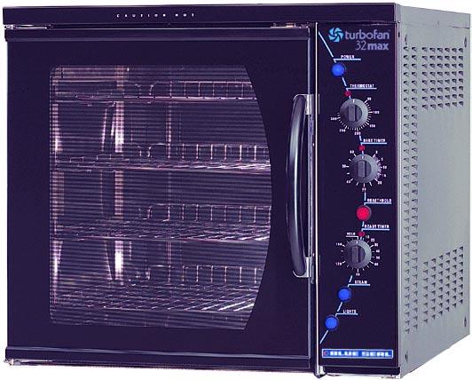
10 3. OPERATION NOTE: A full user s operation manual is supplied with the product and can be used for further referencing of installation, operation and service. 3. DESCRIPTION OF CONTROLS. Power Depress to switch power on or off (switch illuminates when power is on). 2. Thermostat Temperature range C ( F). Indicator illuminates when elements are cycling ON to maintain set temperature Bake Timer Hour bake timer. (Indicator illuminates when time up (0) reached, and buzzer sounds). 4. Roast n Hold Depress switch to activate Roast n Hold function. (Switch illuminates when ON) Roast Timer 3 Hour roast timer. (Indicator illuminates when time up (0) reached, and product held at 75 C (67 F) Steam Switch Push switch to activate water injection. (Water injects into oven while the button is depressed). 7. Light Switch Push switch to activate lights
11 3.2 EXPLANATION OF CONTROL SYSTEM The E32M and E32MS Turbofan convection ovens feature multi-function operator controls for which a correct understanding of their operation is required before carrying out any service or fault repair work. The control device functions are explained as follows: A power switch on the control panel isolates power to the controls of the oven. With the power switch Off all functions of the oven are inoperable. With the power switch On (illuminated) power is directly supplied to the 60 minute bake timer, steam (water injection) switch, door microswitch, light switch, and the temperature control circuit. The oven circulation fan will operate whenever the power switch is on. The control panel light switch will turn the oven lights on when the door is closed. The oven lights will come on automatically when the door is open, as this is controlled by the door microswitch. The oven fan and heating elements are also controlled by the door microswitch, and will therefore only operate when the door is closed. The 60 minute timer is a mechanical timer and can therefore be operated with the oven s power switch On or Off. However, only with the oven s power switch On will the switch contacts of the 60 minute timer turn on the time-up buzzer and illuminate the time-up indicator on the control panel. The buzzer and time-up indicator provide indication that the time setting has run down to zero and at this point will remain On continuously until the 60 minute timer has been manually set back to the Off (vertical) position. The 60 minute timer does not control any other part of the oven s operating system as this timer is independent of the temperature control and heating system. The steam (water injection) switch on the control panel can be operated whenever the power switch is On. The switch is momentary like the light switch and when depressed, will operate the electric solenoid valve at the rear of the oven and inject water across the elements and fan from the flat spray (vertical) nozzle positioned at the rear of the oven elements. Releasing the steam button will close the solenoid valve. This feature is used to instantaneously add steam into the oven. The temperature control of this oven is with a capillary type thermostat which can be set to a required cooking temperature. The control panel indicator light above the thermostat knob cycles On and Off with the thermostat to indicate when the elements are on and the oven is heating. The E32M and E32MS Turbofan convection ovens have 6.5 kw of electric heating elements, comprising of a 3 kw inner coil, and a 3.5 kw outer coil, both of which make up the element assembly around the oven fan. The elements are switched on and off by the main oven thermostat or hold thermostat via a four-pole 25 Amp contactor located inside the control housing. Only two poles of the contactor are used, one for each element coil. Power to the oven thermostat is supplied from the door microswitch, and will therefore only switch the elements on if the oven door is closed. The circulation fan on the E32M and E32MS ovens reverses direction every 90 seconds for a 50Hz supply (every 75 seconds for 60Hz). Prior to a change of direction the fan motor is switched off for 0 seconds (8½ seconds for 60Hz) to allow the motor/fan to slow down. Cycling of the fan motor is controlled by a continuous cam timer with electric motor. The timer has two cams and switches which supply power alternately to one of two motor supply wires, causing the motor to alternate direction. During the fan motor slow down periods, both cam switches are open and power is not supplied to either of the motor supply wires. When the oven door is opened or the power is switched off the cams will stop. When the oven door is closed or the power switched back on the cam timer will resume its cycle from the point where it stopped. The fan motor is a split phase continuous capacitor motor with the capacitor externally connected across the motor supply leads. The motor also incorporates an internal thermal trip switch for overheat protection which is auto resetting. The E32M and E32MS Turbofan convection ovens feature a Roast-and-Hold system which can be used to automatically set the oven to a fixed holding temperature at the end of a timed cooking period. When the Roast-and- Hold switch is turned On the switch will illuminate and switch on a hold relay found inside --
12 the control panel. When the relay is switched ON a normally closed switch pole on the relay is opened and the normal power supply to the oven thermostat is isolated. A second normally open switch pole is closed and this provides power to the 3 hour roast timer. If the roast timer is in the Hold (vertical) position the timer switch contacts will be in their normally closed position and supply power directly to the Hold thermostat located behind the control panel. The Hold thermostat is factory set to 75 C (67 F) and will supply power to the heating elements through the heating contactor as required to maintain its preset temperature. The following Troubleshooting Guide should be used to identify any incorrect oven operation. On correct identification of the operating fault the Troubleshooting Guide will make reference to the corrective action required, or refer to the Fault Diagnosis section and/or Service section to assist in correction of the fault. The thermostat heating light will also cycle On/Off as the Hold thermostat maintains temperature. In the Roast-and Hold mode the 3 hour timer can be set to a selected roasting time. During this time period the normally open switch contacts of the timer are closed. The timer has two change over switches and in this position one is used to supply power to its timing motor and the other is used to switch power directly to the main oven thermostat. During the 3 hour timer run-down period the oven temperature will be controlled by the main oven thermostat to the set temperature and operate as previously described. When the 3 hour timer has run down and reached the Hold position the two switch contacts change over to their normally closed position which isolates power from the timer motor and the oven thermostat. It also switches power back to the oven hold thermostat. At this point the temperature control is now maintained by the hold thermostat as previously described. To cancel the hold circuit the Roast-and-Hold switch is turned Off. This turns off the contactor which removes power from the 3 hour timer and closes the contactor pole on the contactor that feeds the main oven thermostat. The Hold indicator light above the 3 Hour timer will illuminate whenever the oven is operating in hold mode (Roast n Hold selected, and 3 Hour timer at zero position). The factory preset hold thermostat can be adjusted as required to change the holding temperature if necessary. Refer Service section for this procedure. -2-
13 4. MAINTENANCE WARNING: ALL INSTALLATION AND SERVICE REPAIR WORK MUST BE CARRIED OUT BY QUALIFIED PERSONS ONLY. 4. CLEANING WARNING: ALWAYS TURN THE POWER SUPPLY OFF BEFORE CLEANING. IMPORTANT: THIS UNIT IS NOT WATER PROOF. DO NOT USE A WATER JET SPRAY TO CLEAN INTERIOR OR EXTERIOR OF THIS UNIT. EXTERIOR Clean with a good quality stainless steel cleaning compound. Harsh abrasive cleaners may damage the surface. OVEN SEALS To remove, hold at their centre point and pull forward until they unclip. Remove side seals first, then top and bottom. The seals may be washed in the sink, but take care not to cut or damage them. To replace, ensure that the lip is facing the oven opening. Fit the top and bottom seals first, then the side seals. OVEN DOOR GLASS Clean with conventional glass cleaners. INTERIOR Ensure that the oven chamber is cool. Do not use wire brushes, steel wool or other abrasive materials. Clean the oven regularly with a good quality oven cleaner. Take care not to damage the fan or the tube at the right side of the oven which controls the thermostat. OVEN RACKS To remove, slide out to the stop position, raise the front edge up, and lift out. SIDE RACKS To remove, lift front top to disengage and slide rack forward. To replace, slide top rear slot in rack onto rear stud, then engage front keyhole on front stud. LAMP GLASS To remove glasses, unscrew anti-clockwise. To replace, screw in clockwise. IMPORTANT: DO NOT OVER TIGHTEN LAMP GLASS. -3-
14 4.2 ROUTINE PROCEDURES PROCEDURE INTERVAL DOOR SEALS Check for deterioration. 2 months DOOR PIVOT BUSHES Check for wear. 2 months DOOR CATCHES ELEMENT Ensure that catches are adjusted such that the door closes properly. Check that element resistance is correct to it s rating (refer 6.3.5). 2 months 2 months WATER NOZZLE Check for liming in water nozzle. 2 months -4-
15 5. TROUBLE SHOOTING WARNING: ALL INSTALLATION AND SERVICE REPAIR WORK MUST BE CARRIED OUT BY QUALIFIED PERSONS ONLY. FAULT POSSIBLE CAUSE REMEDY THE OVEN DOES NOT OPERATE / START FAN DOESN T OPERATE FAN ONLY OPERATES IN ONE DIRECTION OVEN LIGHT NOT ILLUMINATING - DOOR OPEN (AUTOMATICALLY ON) OVEN LIGHT NOT ILLUMINATING - DOOR CLOSED (MANUALLY SWITCHED ON) The mains isolating switch on the wall, circuit breaker or fuses are off at the power board. The power switch on the oven is off. Incorrect electrical supply. (Refer fault diagnosis 6..) Power switch on unit faulty. (Refer fault diagnosis 6..) Door not closed. Fan obstructed. Door microswitch is out of adjustment. (Refer fault diagnosis 6..2) Door microswitch faulty. (Refer fault diagnosis 6..2) Motor timer faulty. (Refer fault diagnosis 6..2) Motor capacitor faulty. (Refer fault diagnosis 6..2) Fan motor faulty. Wiring. Motor timer faulty. (Refer fault diagnosis 6..2) Blown bulb. No power to light. (Refer fault diagnosis 6..3) Blown bulb. Light switch faulty. (Refer fault diagnosis 6..4) Turn on. Depress switch. Switch will illuminate. Ensure electrical supply correct. (Refer service section 6.3.4) Close door. Clear obstruction. Adjust. (Refer service section 6.4.2) (Refer service section 6.3.2) (Refer service section 6.3.8) (Refer service section 6.3.9) (Refer service section 6.3.7) Check and tighten any loose wiring. (Refer service section 6.3.3) (Refer service section 6.3.) Correct fault. (Refer service section 6.3.) (Refer service section 6.3.4) -5-
16 FAULT POSSIBLE CAUSE REMEDY NO WATER INJECTION / STEAM CONTINUOUS WATER OUT OF OVEN WATER NOZZLE 60 MINUTE TIMER WILL NOT TIME DOWN 60 MINUTE TIMER INACCURATE BELOW 20 MINUTES 60 MINUTE TIMER NO TIME UP BUZZER 60 MINUTE TIMER NO TIME UP INDICATOR NO HEAT NO TEMPERATURE CONTROL (TEMPERATURE OVERRUN) Water not turned on. Oven water nozzle blocked. Fault with water valve. (Refer fault diagnosis 6..5) Steam switch faulty. With oven on only Electrical fault. (Refer fault diagnosis 6..6) With oven on or off - water valve faulty or requires cleaning. Timer faulty. Timer not set correctly. Zero (time up) position not set correctly. Buzzer faulty. (Refer fault diagnosis 6..7) Timer not switching on buzzer. (Refer fault diagnosis 6..7) Indicator faulty. (Refer fault diagnosis 6..8) No power to thermostat. (Refer fault diagnosis 6..9) Thermostat faulty. (Refer fault diagnosis 6..9) Heating contactor faulty. (Refer fault diagnosis 6..9) Element faulty (blown). (Refer fault diagnosis 6..9) Heating contactor faulty. (Refer fault diagnosis 6..9) Thermostat faulty. (Refer fault diagnosis 6..0) Turn water on at water supply. Remove, clean or replace. (Refer service section 6.3.4) Service or replace as required. (Refer service section 6.3.2, 6.3.3) (Refer service section 6.3.4) Correct electrical fault. Service or replace as required. (Refer service section 6.3.2, 6.3.3) (Refer service section 6.3.7) For timer settings below 20 minutes, always rotate past 20 minutes, then back to desired time. (Refer service section 6.4.6) (Refer service section 6.3.5) (Refer service section 6.3.7) (Refer service section 6.3.3) Identify fault and correct. (Refer service section 6.3.9) (Refer service section 6.3.) (Refer service section 6.3.5) (Refer service section 6.3.) (Refer service section 6.3.9) -6-
17 FAULT POSSIBLE CAUSE REMEDY SLOW RECOVERY ELEMENT NOT WORKING NO THERMOSTAT HEATING INDICATOR ROAST TIMER (80 MINUTE) WILL NOT TIME DOWN NO HOLD INDICATOR HOLDING TEMPERATURE INCORRECT DOOR DOES NOT CLOSE Oven in Roast n Hold mode. Overloading of oven. Electrical supply incorrect. Fan not working. Thermostat out of calibration. (Refer fault diagnosis 6..) Element not working. Element faulty (blown). (Refer fault diagnosis 6..9) Indicator faulty. (Refer fault diagnosis 6..2) Roast n Hold switch not depressed. No power to timer / timer faulty.. (Refer fault diagnosis 6..3) Roast n Hold switch faulty. (Refer fault diagnosis 6..3) Faulty indicator. (Refer fault diagnosis 6..4) Faulty timer. (Refer fault diagnosis 6..4) Hold thermostat set temperature incorrect. Hold thermostat faulty. (Refer fault diagnosis 6..5) Tray in way of door. Door seal obstruction. Door handle installed incorrectly. Door catch setting incorrect. Door pivot bushes / pins worn. Switch off Roast n Hold. Reduce oven loading. Check supply voltage is as per rating plate voltage. Check fan operation. Correct calibration. (Refer service section 6.4.) Correct element fault. (Refer Fault: No Heat) (Refer service section 6.3.5) (Refer service section 6.3.3) Depress switch. Switch will illuminate. Correct electrical fault / replace timer. (Refer service section 6.3.8) (Refer service section 6.3.4) (Refer service section 6.3.3) (Refer service section 6.3.8) Adjust to correct temperature. (Refer service section 6.4.5) (Refer service section 6.3.0) Correctly position tray in rack. Correctly install door seal. (Refer service section ) Ensure handle is fitted correctly. Adjust. (Refer service section 6.4.3) (Refer service section ) -7-
18 FAULT POSSIBLE CAUSE REMEDY DOOR SEAL LEAKS Door seal damaged. Door seal incorrectly fitted. Door catch setting incorrect. Door pivot bushes / pins worn. Door catch striker plate worn. (Refer service section ) Correctly install door seal. (Refer service section ) Adjust. (Refer service section 6.4.3) (Refer service section ) -8-
19 6. SERVICE PROCEDURES WARNING: ENSURE POWER SUPPLY IS SWITCHED OFF BEFORE SERVICING. WARNING: ALL INSTALLATION AND SERVICE REPAIR WORK MUST BE CARRIED OUT BY QUALIFIED PERSONS ONLY. SECTION PAGE NO. 6. FAULT DIAGNOSIS Oven Does Not Operate / Start Fan Does Not Operate Oven Light Not Illuminating Door Open Oven Light Not Illuminating Door Closed No Water Injection / Steam Continuous Water Out Of Oven Water Nozzle Minute Timer No Time Up Buzzer Minute Timer No Time Up Indicator No Heat No Temperature Control (Temperature Overrun) Slow Recovery No Thermostat Heating Indicator Roast Timer (80 Minute) Will Not Time Down No Hold Indicator Holding Temperature Incorrect ACCESS Control Panel Service Panel (Side Panel) Control Panel (Rear) REPLACEMENT Light Bulb / Glass Door Microswitch Neon Indicator Power / Roast / Lights / Water Switches Buzzer Hold Relay Bake Timer Roast Timer Thermostat Hold Thermostat Heating Contactor Water Solenoid Water Solenoid Cleaning Spray Nozzle Elements Fan Motor Motor Timer Motor Capacitor Outer Glass
20 6.3.2 Inner Glass Door Seals Door Pivot Bushes Stainless Steel Door Outer Glass Stainless Steel Door Inner Glass ADJUSTMENT / CALIBRATION Thermostat Calibration Door Microswitch Adjustment Reversing the Door Door Roller Catch Adjustment Door Alignment Hold Temperature Adjustment Minute Timer Zero Position Adjustment
 terminals of terminal block is the voltage as stated on the unit s electrical")

21 6. FAULT DIAGNOSIS 6.. OVEN DOES NOT OPERATE / START Incorrect electrical supply Check that the voltage across phase and neutral (L and L2) terminals of terminal block is the voltage as stated on the unit s electrical rating plate. If incorrect, check electrical connection of supply wiring and / or check electrical supply. Power switch faulty Check if power switch latches. If the switch does not latch, then switch is faulty replace. With switch latched, check voltage across terminal one to terminal three or four. If there is no voltage, check for fault in wiring. Check voltage across terminal two to terminal three or four. If there is no voltage, then switch is faulty replace. NOTE: When power switch is latched, it should illuminate if operating correctly FAN DOESN T OPERATE Microswitch out of adjustment Open oven door and manually depress door microswitch actuator at top right of oven. If this activates the fan, then the microswitch actuator arm inside control cavity requires adjustment. Microswitch faulty Check voltage from microswitch terminals to neutral. With the door closed there should be power to the com terminal and the n.o. terminal. With the door open there should be power to the com terminal and the n.c. terminal. If not, microswitch is faulty replace. Microswitch n.c. Fan motor timer faulty With oven switched on, and door closed, ensure that the cams on the motor timer are rotating. Motor Cams (Rotate one revolution every 3 minutes) Figure 6..2 If cams are rotating, then isolate the power supply from the oven. Remove the bottom wire from the left hand switch terminals. Rotate the cams manually whilst testing for continuity through the left hand switch. Check that the continuity cycles as the cams are rotated. Re-secure the left hand wire, and then repeat test for right hand switch. When operating, 50Hz models should cycle the power for approximately 80 seconds through each switch, with a 0 second delay between each cycle. On 60Hz models the power should cycle for approximately 65 seconds through each switch, with an 8 second delay between each cycle. If there is no continuity, or the continuity does not cycle correctly then timer is faulty - replace. Fan motor capacitor faulty Ensure that oven is isolated from the power supply. Disconnect the two capacitor wires. Briefly short across the capacitor terminals, to ensure that it is fully discharged. Using a multimeter, measure the resistance across capacitor terminals. The resistance should start low and quickly increase to infinity within 5-0 seconds. If the resistance does not increase at all, then the capacitor is shorted - replace. If the capacitor is infinite resistance straight away then it is open-circuit - replace. If the resistance never goes very high then the capacitor is leaky - replace. n.o. Figure 6.. com -2-
. If the bulb is OK, check lamp housing. Replace if faulty.")

22 6..3 OVEN LIGHTS NOT ILLUMINATING - DOOR OPEN (AUTOMATICALLY ON) No power to lights Check the supply voltage across lamp housing terminals at RH side rear of oven. If the voltage is correct, replace the bulb (if faulty). If the bulb is OK, check lamp housing. Replace if faulty. If there is no voltage, open oven door and manually depress door microswitch actuator at bottom right of oven. If this activates the lights, then the microswitch actuator arm behind the control panel requires adjustment. Check voltage across micro-switch terminals to neutral. With the door open there should be power to the com terminal and the n.c. terminal. If not, microswitch is faulty replace. n.c. Check voltage to the bottom terminal of the switch. If there is no voltage, then check wiring. With switch depressed, check for voltage at top terminal. If there is no voltage then replace switch. If voltage correct, check wiring to solenoid coil. If power supply to the coil is correct, disconnect wiring to coil and check the resistance of the coil windings. Correct coil resistance: 3650 ohms NOTE: If open circuit / high resistance, then the coil is faulty replace. If coil resistance is correct, rewire and listen for an audible solenoid click when the steam switch is depressed. If solenoid can be heard functioning, and oven water nozzle is not blocked, then remove water solenoid and fittings and check for blockages. com Figure 6..3 Microswitch 6..4 OVEN LIGHTS NOT ILLUMINATING - DOOR CLOSED (MANUALLY SWITCHED ON) Light switch faulty Check voltage to the bottom terminal of the switch. If there is no voltage, then check wiring. With switch depressed, check voltage at top terminal. If there is no voltage, then replace the switch. If voltage is correct, then check wiring to light. NOTE: Alternately, perform a continuity test across the terminals with the light switch depressed CONTINUOUS WATER OUT OF OVEN WATER NOZZLE Water solenoid electrical fault With control panel steam switch not depressed, check for power supply across solenoid coil. If there is power to the coil, then check wiring and steam switch (refer 6..5) MINUTE TIMER NO TIME UP BUZZER Buzzer faulty With timer in zero position, check the buzzer at side of control panel (inside) for voltage across terminals. If voltage is correct then buzzer is faulty replace. If there is no voltage, then check wiring. Buzzer 6..5 NO WATER INJECTION / STEAM Fault with water valve Check voltage supply across the water valve solenoid coil with the steam switch depressed. If there is no power supply then check the control panel steam switch. Figure


23 Timer not switching on buzzer With timer in zero position, check voltage to top connection (terminal one) and bottom connection (terminal two) of timer. If there is no voltage at terminal one then check wiring. If no voltage at terminal two then timer is faulty replace. NOTE: Timer will continue to run approximately three minutes below zero. Buzzer and time up indicator will continue until the timer is manually switched off (to vertical position) MINUTE TIMER NO TIME UP INDICATOR Indicator faulty With the timer in the zero position, check for voltage across the indicator light. If correct, then the indicator light is faulty replace. If there is no voltage then check wiring NO HEAT No power to thermostat Check voltage to terminal 2 on oven thermostat. If there is no voltage then check voltage through terminal 5 and one on hold relay (behind control panel). If there is no voltage to terminal 5 then check wiring. If there is no voltage to terminal then check that the hold relay has no power at relay coil terminal 7. If relay coil is not energised (ie no power at 7) and no power out of terminal, then the relay is faulty replace. 8 Hold Relay 4 Figure 6..5 If relay is energised (ie power at 7) then Roast n Hold switch is on and unit is in hold mode. Turn off Roast n Hold and recheck operation. NOTE: There should be no voltage across these terminals when Roast n Hold is not selected Thermostat faulty Set thermostat to 200 C or 400 F. Check the voltage out of terminal on the thermostat. If there is no voltage then the thermostat is faulty replace. If the voltage is correct and the heating light is on then check all wiring to heating contactor. Heating contactor faulty With thermostat on, check that the heating contactor coil has power to terminal A and voltage across the coil, terminals A and A2. If incorrect check wiring. If voltage is correct, check that contactor pulls in and closes the contacts when power to contactor coil is on. Correct operation will make an audible noise when closing contacts and on the front face of the contactor the contact mechanism will visibly pull in. If not, contactor is faulty replace. If contactor operates correctly, check for continuity through the poles of the contactor when closed. If no continuity through connected poles then contacts are blown and contactor requires replacing. Terminal A Terminal Terminal 2 2 Hold Relay Figure 6..6 Figure 6..7 Terminal A2 Terminal 3 Terminal 4 For checking elements where temperature overrun is occurring, check that contactor releases (opens) when thermostat is switched OFF. If not, contacts of the contactor have welded shut and elements will be ON and heating will be continuous. Contactor is faulty replace. -23-

24 Element faulty (blown) With the thermostat on and heating check voltage across element terminals at RH side of oven. If the voltage is correct then check the current draw of element. If there is no current draw then element is faulty replace. If there is no voltage then check voltage is being supplied to each element coil from the heating contactor. If no voltage to elements, check contactor operation (refer 6..9) and wiring. NOTE: Correct element current draw: 208 V : Inner Coil 2.9A ± 2.5% Outer Coil 5.0A ± 2.5% 220 V : Inner Coil 3.6A ± 2.5% Outer Coil 5.9A ± 2.5% 240 V : Inner Coil 2.5A ± 2.5% Outer Coil 4.6A ± 2.5% 6..0 NO TEMPERATURE CONTROL (TEMPERATURE OVERRUN) Heating contactor faulty Refer 6..9 Thermostat faulty With thermostat in off (vertical) position, the heating indicator should be off. If not then the thermostat is faulty replace NO THERMOSTAT HEATING INDICATOR Indicator faulty Check the voltage across the indicator terminals. If the voltage is correct then the indicator is faulty replace. If there is no voltage then check wiring ROAST TIMER (80 MINUTE) WILL NOT TIME DOWN No power to timer Check the voltage at terminal 5 on underside of the 80 minute timer. Check that one lead of timer motor is connected to terminal five of timer and the other lead is connected to neutral of Roast n Hold switch. If voltage at terminal 5 is correct and wiring is correct then the timer motor is faulty replace timer. If there is no power at terminal 5, check for power supply at terminal 4 of timer. If there is voltage at terminal 4 and not at terminal 6 with timer set, then timer switch is faulty replace timer. 6.. SLOW RECOVERY Thermostat out of calibration Place an accurate digital thermometer probe in centre of oven. Set thermostat to 80 C or 355 F. Close the oven door and allow oven thermostat to cycle on and off twice. Record oven centre temperature for the next thermostat on and off cycle. The thermostat should cycle on and off between 65 C and 95 C or 330 F and 385 F when set to the above temperature. If oven temperature is outside these ranges, then the thermostat requires recalibration. NOTE: Thermostat cycling span should be ±5 C or 27 F Terminal 4 Terminal Terminal 2 Terminal 5 Figure 6..8 Terminal 6 Terminal 3 If terminal 4 voltage is correct, check relay at the base of the control housing behind control panel is latched ON. If relay is ON then check wiring. If relay is not latched ON when Roast n Hold switch illuminated then check the voltage across terminals 7 and 8 of relay coil (fig 6..5). If the voltage is correct but the relay is in the off position then the relay is faulty replace. If there is no voltage across 7 and 8 then check wiring. -24-
25 Roast n Hold switch faulty Check if the switch latches. If the switch does not latch then the switch is faulty replace. With the switch latched, check voltage across terminal to terminal 3 or 4. If there is no voltage then check for fault in wiring. Check voltage across terminal 2 to terminal 3 or 4. If there is no voltage then switch is faulty replace. NOTE: When the switch is latched, it should illuminate if operating correctly. If the voltage is correct, and the thermostat is adjusted above oven temperature, then check for output voltage at terminal (bottom) of hold thermostat. If there is no voltage and the hold thermostat will not switch on then the thermostat is faulty replace. If the voltage is correct but the element is not working then check wiring NO HOLD INDICATOR Indicator faulty Check the voltage across the indicator terminals. If the voltage is correct then the indicator is faulty replace. If there is no voltage then check wiring. Timer faulty NOTE: Timer in HOLD position (vertical) and Roast n Hold switch on (illuminated). Check the voltage at terminal three of timer, with timer in hold position. If the voltage is correct then check wiring. If there is no voltage then check voltage at terminal one of timer. If there is voltage at terminal one, but no voltage at terminal three with timer in hold position then timer switch is faulty replace HOLDING TEMPERATURE INCORRECT Hold thermostat faulty With the power switch on and illuminated, Roast n Hold switch on and illuminated, and the roast (80 minute) timer set to hold, check that the hold indicator is illuminated. With a cold oven (ie room temperature) check that the oven element is heating. Test the voltage across the element terminals at the RH side of oven. If the voltage is correct then refer Fault: No heat (trouble shooting section). If there is no voltage at the element terminals, check the voltage at terminal 2 of the hold thermostat at RH side of control panel (fig 6.3.2). If there is no voltage then check wiring. -25-
 The panel can now be removed.")
26 6.2 ACCESS CONTROL PANEL REAR 6.2. CONTROL PANEL ) Undo the two screws at the bottom of the control panel. Power Switch Heating Indicator Thermostat Bake Time Up Indicator Buzzer Two screws Figure ) The panel can now be removed. When closing the panel ensure wires and thermostat capillary tubes are clear of metal or other terminals SERVICE (SIDE) PANEL ) Undo the four screws holding the panel. Bake Timer Hold Relay Hold Thermostat Roast n Hold Switch Roast n Hold Time Up Indicator Roast Timer Steam Switch Light Switch Figure Figure Four screws 2) Remove side panel. -26-
. Figure 6.3.3 2) From back push neon through front of panel rotating clockwise.")
 remove the wires from the back of the switch, noting their positions. 6.3.2 DOOR MICROSWITCH ) Remove control panel (refer 6.2.) 2) Remove two screws holding microswitch to bracket.")
 Adjust micro-switch (refer 6.4.2). 6.3.5 BUZZER ) Remove control panel (refer 6.2.). 2) Remove two screws holding buzzer / relay bracket to control panel. 6.3.3 NEON INDICATOR ) With control panel open (refer 6.")
27 6.3 REPLACEMENT 6.3. LIGHT BULB / GLASS Neon wires ) Unscrew lamp cover(s). Figure 6.3. Lamp covers 2) Unscrew bulb out of fitting. 3) Screw in replacement bulb. 4) Ensure seal fitted. Screw lamp cover into holder with baffle fitted (do not over tighten). Figure ) From back push neon through front of panel rotating clockwise. 3) Push new neon in from front of panel, and reconnect wires POWER / ROAST / LIGHTS / STEAM SWITCHES ) With control panel open (refer 6.2.) remove the wires from the back of the switch, noting their positions DOOR MICROSWITCH ) Remove control panel (refer 6.2.) 2) Remove two screws holding microswitch to bracket. Switch wires Figure Microswitch 2) From back push switch through front of panel. 3) Push new switch in from front of panel, and reconnect wires. Figure ) Transfer wires to the new switch and reassemble. 4) Adjust micro-switch (refer 6.4.2) BUZZER ) Remove control panel (refer 6.2.). 2) Remove two screws holding buzzer / relay bracket to control panel NEON INDICATOR ) With control panel open (refer 6.2.) remove the wires from the back of the neon. Two screws Figure
 Open control panel (refer 6.2.) and undo two screws securing timer. 6.3.6 HOLD RELAY ) Open control panel (refer 6.2.). 2) Remove two screws securing the relay to the buzzer / relay bracket on the control panel.")
 Reassemble in reverse order. 6.3.9 THERMOSTAT ) Pull knob off front of thermostat 2) Open control panel (refer 6.2.) and undo two screws securing thermostat. 6.3.7 BAKE TIMER ) Remove bake timer knob by pulling it firmly away from control panel.")
 Withdraw old timer and insert new timer, securing with screws. 5) Replace knob. Figure 6.3.9 3) Transfer wires to new thermostat. 4) Open oven door, remove racks and fan baffle rack.")
28 3) Withdraw and remove two screws holding buzzer to bracket. 4) Transfer wires to new buzzer. 5) Reassemble in reverse order ROAST TIMER ) Remove roast timer knob by pulling it firmly away from control panel. 2) Open control panel (refer 6.2.) and undo two screws securing timer HOLD RELAY ) Open control panel (refer 6.2.). 2) Remove two screws securing the relay to the buzzer / relay bracket on the control panel. Two screws Two screws Figure ) Transfer wires to new timer. 4) Withdraw old timer and insert new timer, securing with screws. 5) Replace knob. Figure ) Withdraw and transfer wires to new relay. 4) Reassemble in reverse order THERMOSTAT ) Pull knob off front of thermostat 2) Open control panel (refer 6.2.) and undo two screws securing thermostat BAKE TIMER ) Remove bake timer knob by pulling it firmly away from control panel. 2) Open control panel (refer 6.2.) and undo two screws securing timer. Two screws Two screws Figure ) Transfer wires to new timer. 4) Withdraw old timer and insert new timer, securing with screws. 5) Replace knob. Figure ) Transfer wires to new thermostat. 4) Open oven door, remove racks and fan baffle rack. Loosen two screws securing thermostat phial bracket. Thermostat phial bracket Figure

 Insert new thermostat phial. 6) Re-assemble in reverse order. The hold Hold thermostat phial Control thermostat phial Towards the door 6.3.")
 Clip new contactor onto gear plate. 4) Transfer wires from old contactor to new contactor, ensuring all wires are in their correct positions. 6.3.2 WATER SOLENOID Figure 6.3.2 Two screws 2) Remove the two screws securing the hold thermostat to the bracket, and then fit the new thermostat in its place.")
29 5) Withdraw old thermostat phial through side of oven. Note position in phial bracket. 6) Insert new thermostat. 7) Re-assemble in reverse order. NOTE: Ensure that the thermostat phials are located in their correct positions. The main thermostat probe must be on the side closest to the door. The hold thermostat must be on the side closest to the fan and elements. 4) Withdraw the old hold thermostat phial through the side of the oven. Note the position of the phial in the bracket. 5) Insert new thermostat phial. 6) Re-assemble in reverse order. NOTE: Ensure that the thermostat phials are located in their correct positions. The main thermostat probe must be on the side closest to the door. The hold Hold thermostat phial Control thermostat phial Towards the door 6.3. HEATING CONTACTOR ) Remove the right hand service panel (refer 6.2.2). 2) Unclip contactor from the gear plate. Contactor Figure HOLD THERMOSTAT ) Open control panel (refer 6.2.) and undo two screws securing hold thermostat bracket. Figure ) Clip new contactor onto gear plate. 4) Transfer wires from old contactor to new contactor, ensuring all wires are in their correct positions WATER SOLENOID Figure Two screws 2) Remove the two screws securing the hold thermostat to the bracket, and then fit the new thermostat in its place. 3) Transfer wires to new thermostat. 3) Open oven door, remove racks and fan baffle rack. Loosen the thermostat phial bracket (refer figure 6.3.0). ) Ensure water supply is turned off. 2) To access the solenoid, remove the right hand service panel (refer 6.2.2) 3) Disconnect all water connections from the water solenoid. 4) Remove water solenoid from oven by removing two screws securing the water solenoid to its mounting bracket. Water solenoid Figure
 Check for correct operation of the oven water injection. 6.3.5 ELEMENTS ) Remove service panel (refer 6.2.2) and baffle.")
 Remove the sieve from the water valve assembly by pulling firmly away from the assembly with a pair of pliers. Figure 6.3.")
 Replace the sieve and reconnect the water supply. 6.3.4 SPRAY NOZZLE ) Inside the oven remove the RH side fan baffle, then unscrew the spray nozzle.")
 RTV silicone sealant to seal element against side wall of oven. Element Rating: 208-220 V Inner Element 7.")
 Clean or replace as required, ensuring debris free on re-assembly.")
30 5) Carefully withdraw solenoid. 6) Replace or service solenoid as required. 7) To reinstall, reverse procedure. 8) Check water connections do not leak. 9) Check for correct operation of the oven water injection ELEMENTS ) Remove service panel (refer 6.2.2) and baffle. 2) Remove the wires from the elements. Element wires WATER SOLENOID CLEANING ) Disconnect water supply from the water solenoid. 2) Remove the sieve from the water valve assembly by pulling firmly away from the assembly with a pair of pliers. Figure ) Unscrew the elements from inside the oven. Element screw Sieve Figure ) Clean the sieve, removing all dirt and grime. 5) Replace the sieve and reconnect the water supply SPRAY NOZZLE ) Inside the oven remove the RH side fan baffle, then unscrew the spray nozzle. Figure ) Pull elements carefully to remove. Silicone sealant may require effort to remove elements. 4) Replace and re-assemble in reverse order. Use high temperature (232 C / 450 F minimum) RTV silicone sealant to seal element against side wall of oven. Element Rating: V Inner Element 7.0 ohms Outer Element 4. ohms V Inner Element 9.4 ohms Outer Element 7.0 ohms FAN ) With baffle removed undo the grub screw securing the fan to the motor shaft. Spray nozzle Figure ) Clean or replace as required, ensuring debris free on re-assembly. 3) Ensure that the spray nozzle is installed in the vertical position. Figure Grub screw 2) Remove the fan from the shaft, replace, and reassemble. -30-
 Undo the four screws holding the motor in place (from inside the oven) and remove motor. Capacitor Four screws Figure 6.3.20 Figure 6.3.22 3) Remove the capacitor wires, noting their positions.")
 Remove the screws securing the motor timer to the gear plate. 6.3.20 OUTER GLASS ) Open door. 2) Loosen the two screws securing the bottom pivot whilst supporting the door.")
 Fit the new timer to the gear plate, and transfer the wires from the old timer. 3) Remove screws securing door handle, and remove the handle from the door assembly.")
31 6.3.7 MOTOR ) Remove fan (refer 6.2.6). 2) Remove the right hand service panel and then remove the motor wires. 3) Undo the four screws holding the motor in place (from inside the oven) and remove motor. Capacitor Four screws Figure Figure ) Remove the capacitor wires, noting their positions. 4) Fit new capacitor and reassemble in reverse order. 4) Replace motor and reassemble in reverse order MOTOR TIMER ) Remove the right hand service panel (refer 6.2.2). 2) Remove the screws securing the motor timer to the gear plate OUTER GLASS ) Open door. 2) Loosen the two screws securing the bottom pivot whilst supporting the door. The pivot can now be lowered, and the door removed from the oven. Motor timer Bottom pivot Figure Figure ) Fit the new timer to the gear plate, and transfer the wires from the old timer. 3) Remove screws securing door handle, and remove the handle from the door assembly. Screws MOTOR CAPACITOR ) Remove the right hand service panel (refer 6.2.2). 2) Undo the nut securing the capacitor to the mounting bracket. Figure
 Lift outer glass away from door.")


 To replace, ensure the silicone rubber seal has not been displaced.")
 Door bushes can now be removed and replaced. Door pivot bush Figure 6.3.29 4) Reinstall door by reversing steps one to two of section 6.")
32 4) Remove four screws in top trim and four screws in bottom trim of door, and remove trim panels. Four screws INNER GLASS Figure Four screws 5) Lift outer glass away from door. 6) To replace, ensure that the two silicone rubber seals are in place on the left hand and right hand side of the door frame. Clean the inside of the glass and refit it, ensuring that the silicone rubber seals cover the outer edges of the glass. Refit the trim panels. ) Remove the outer glass (refer ). Uncrimp the retaining lugs of the window spacer and remove the spacer and glass. Figure ) Refit new seals. Door seals Note: Fit top and bottom seals first, with open side of seal facing downwards. Fit side seals with open side facing outwards DOOR PIVOT BUSHES ) Remove door as per steps one and two of section ) Remove the top and bottom pivot brackets (two screws). Two screws Retaining lugs Figure Figure ) To replace, ensure the silicone rubber seal has not been displaced. Clean the glass and refit it. Place the window spacer in position and crimp the retaining lugs over to hold the glass in place. Refit outer glass as above. 3) Door bushes can now be removed and replaced. Door pivot bush Figure ) Reinstall door by reversing steps one to two of section DOOR SEALS ) Open oven door. 2) To remove, hold at their centre point and pull forward until they unclip -32-
 Remove the top and bottom pivots (two screws each), and the door handle and roller catches (two screws top and bottom). Top pivot 3) Replace with new glass.")
 The stainless steel door outer can now be removed.")
33 STAINLESS STEEL DOOR - OUTER GLASS ) Remove the door as per steps one and two of section ) Remove the top and bottom pivots (two screws each), and the door handle and roller catches (two screws top and bottom). Top pivot 3) Replace with new glass. Ensure when replacing that the side with the L mark is inside the door (not inside the oven). This ensures the correct operation of the Low E glass. 4) Reassemble and refit door to the oven. Door handle Bottom pivot Figure ) The stainless steel door outer can now be removed. 4) To replace the outer glass, simply remove and replace, taking care that the outer seals are positioned correctly around the glass edge. Ensure when replacing that the side with the L mark is inside the door (not on the front of the oven). This ensures the correct operation of the Low E glass. 5) Reassemble in reverse order and refit door to oven STAINLESS STEEL DOOR - INNER GLASS ) Remove the outer glass (refer ). 2) Uncrimp the retaining angles and remove inner glass. Retaining angles Figure
")
 Remove thermostat knob by pulling it firmly away from control panel.")
34 6.4 ADJUSTMENT / CALIBRATION DOOR MICROSWITCH ADJUSTMENT 6.4. THERMOSTAT CALIBRATION IMPORTANT: IF THE OVEN T EMPERAT URE NEEDS T O BE INCREASED, ENSURE THAT THE THERMOSTAT IS IN THE OFF POSITION BEFORE CARRYING OUT ADJUSTMENT. IF OVEN TEMPERATURE NEEDS TO BE DECREASED, ENSURE THERMOSTAT IS IN THE MAXIMUM TEMPERATURE POSITION BEFORE CARRYING OUT ANY ADJUSTMENT. ) Open oven door. 2) Open control panel (refer 6.2.). 3) With fingers, bend actuator arm of microswitch so that switch operates when door is in closed position. Actuator arm Figure Thermostat Calibration nut REVERSING THE DOOR Figure 6.4. ) Remove thermostat knob by pulling it firmly away from control panel. 2) Adjust the calibration nut located at the base of the thermostat shaft. Calibration nut If desired, a left hand hinged oven door can be changed to a right hand hinged door (or vice versa). ) While supporting the door, undo the door hinges from the oven. Remove the door. 2) The bottom right door catch plate should now be transferred to the top left of the oven (a), and the top right door catch plate transferred to the bottom left of the oven (b). a Figure To increase oven temperature, turn the calibration nut anticlockwise. To decrease oven temperature, turn the calibration nut clockwise. Adjustment of the calibration nut by angular will alter oven temperature by approximately 2 C (3.6 F). 3) Refit the knob to the thermostat.. 4) Recheck the oven thermostat calibration. 5) Repeat procedure if necessary. b Figure ) Secure the door hinges and oven door to the right hand side of the oven door opening. 4) If alignment of the door is necessary, the five screws along the bottom of the oven can be loosened, and the door moved a small amount to ensure that it is square with the oven. Tighten the screws when the correct door position is attained. -34-
 Open control panel (refer 6.2.) to gain access to the hold thermostat (located inside the control panel).")
 Remove the two screws securing the roller catch to the door and withdraw the catch. 3) Tighten or loosen the nuts on the catch assembly to adjust the height of the roller.")
 Remove 60 minute timer knob by pulling it firmly away from control panel. 2) Open control panel (refer 6.2.). Loosen two screws on control panel holding 60 minute timer.")
35 5) If necessary the roller catches can be removed from the door (after removing handle on stainless steel doors) to adjust height settings for correction of door catch operation DOOR ROLLER CATCH ADJUSTMENT HOLD TEMPERATURE ADJUSTMENT ) Open control panel (refer 6.2.) to gain access to the hold thermostat (located inside the control panel). 2) The hold temperature of the oven can be adjusted by turning the hold thermostat dial to the desired hold temperature. ) Open the door. 2) Remove the two screws securing the roller catch to the door and withdraw the catch. 3) Tighten or loosen the nuts on the catch assembly to adjust the height of the roller. Roller catch Hold thermostat Adjustment nuts Figure Figure ) Refit catch to door and check operation. Adjust again if necessary DOOR ALIGNMENT ) Loosen the five screws along the bottom edge of the oven front MINUTE TIMER ZERO POSITION ADJUSTMENT ) Remove 60 minute timer knob by pulling it firmly away from control panel. 2) Open control panel (refer 6.2.). Loosen two screws on control panel holding 60 minute timer. Two screws Figure ) The timer can now be rotated a small amount to ensure that the buzzer sounds and indicator illuminates at the zero (time up) position. Five screws Figure ) Adjust the door position to ensure that it is square with the oven. Tighten the screws. -35-
36 7. ELECTRICAL CIRCUIT SCHEMATIC L Ø L2 N E 2 POWER 4 3 Hr TIMER WATER LIGHTS B TIME UP LIGHTS 2x40W BUZZER WATER SOLENOID M 2 C NC C C No Nc No Nc DOOR M'SWITCH NO 3uF HOLD RELAY MOTOR TIMER FAN MOTOR 00W M HOLD SWITCH HOLD M ROAST TIMER THERMOSTAT 2 HOLD T'STAT 2 HEATING CONTACTOR A A HEATING ELEMENTS TOTAL LOADS: 208V 580W 220V 6500W 230V 6000W 240V 6500W BLUE BLACK BROWN -36-
37 8. ELECTRICAL WIRING DIAGRAM 2 22 T/STAT LIGHTS COM NO DOOR SWITCH MICROSW NC WHITE BLACK N P P E N P E N FAN MOTOR BROWN COM No Nc BLACK BLUE 49 BLACK BLUE POWER SWITCH EARTH STUD HOLD ROAST & 3 T/STAT HOLD hr TIMER 28 CONTROL PANEL EARTH TAG 8 48 T/STAT INDICATOR BAKE TIMER 0 INDICATOR BUZZER BAKE TIMER RELAY STEAM SWITCH ELEMENTS MOTOR TIMER CAPACITOR A A CONTACTOR OVEN LIGHT OVEN LIGHT E N L WATER SOLENOID TERMINAL BLOCK -37-
38 9. SPARE PARTS Controls Power Switch Thermostat Knob - Thermostat Neon Indicator 0760 Bake Timer 0794 Buzzer Switch- Roast n Hold 049 Roast n Hold Timer Knob - Bake Timer / Roast n Hold Timer Steam Switch Light Switch Contactor - Elements 0249 Relay - Roast n Hold Hold Thermostat Microswitch Oven Lamp Glass Silk Gasket 0352 Oven Lamp - 40W Miniature Edison Screw Motor & Elements Element Assembly V Element Assembly V Fan Motor Capacitor 3uF Motor Timer V Motor Timer V Fan Steam System Water Solenoid Spray Nozzle Assembly Water Inlet Elbow Washer Door Door Seal (Side) Door Seal (Top/Bottom) Top Hinge Bottom Hinge Roller Catch Door Bush Door Handle (E32M) Door Handle Bracket (E32M) Door Outer Glass (E32M) Door Inner Glass (E32M) Door Handle (E32MS) Door Glass (E32MS) Racks Oven Side Rack LH Fan Baffle 0568 Oven Rack Stacking Kit Double Stacking Kit -38-
 DOUBLE STACKING")
 FOOT OPTION (PART")
 A25")

39 0. ACCESSORIES OVEN RACKS (PART NO 568) DOUBLE STACKING KIT (PART NO 02502) 00 MM (FOUR INCH) FOOT OPTION (PART NO 3048) 25 MM (ONE INCH) FOOT OPTION (PART NO 3908) A25 STAINLESS STEEL STAND COOKIE KIT SIX TRAY OPTION (PART NOS 756 & 757) -39-
E32 CONVECTION OVEN SERVICE MANUAL
 E32 CONVECTION OVEN SERVICE MANUAL Applies to units from S/N 40256-1- WARNING: ALL INSTALLATION AND SERVICE REPAIR WORK MUST BE CARRIED OUT BY QUALIFIED PERSONS ONLY. -2- CONTENTS This manual is designed
E32 CONVECTION OVEN SERVICE MANUAL -1- Revision 1/F3508
 E32 CONVECTION OVEN SERVICE MANUAL -1- WARNING: ALL INSTALLATION AND SERVICE REPAIR WORK MUST BE CARRIED OUT BY QUALIFIED PERSONS ONLY. -2- CONTENTS This manual is designed to take a more in depth look
E25 CONVECTION OVEN E25MS CONVECTION OVEN SERVICE MANUAL
 E25 CONVECTION OVEN E25MS CONVECTION OVEN SERVICE MANUAL E25 Convection Oven -- WARNING: ALL INSTALLATION AND SERVICE REPAIR WORK MUST BE CARRIED OUT BY QUALIFIED PERSONS ONLY. E25 Convection Oven -2-
E26 CONVECTION OVEN SERVICE MANUAL. Revision 1/F
 E26 CONVECTION OVEN SERVICE MANUAL -1- WARNING: ALL INSTALLATION AND SERVICE REPAIR WORK MUST BE CARRIED OUT BY QUALIFIED PERSONS ONLY. -2- CONTENTS This manual is designed to take a more in depth look
Manual P/N M0MG32MS. Revision 6/F3587 February, 2005
 G3MS CONVECTION OVEN SERVICE MANUAL Revision 6/F3587 February, 005 Manual P/N M0MG3MS WARNING: ALL INSTALLATION AND SERVICE REPAIR WORK MUST BE CARRIED OUT BY QUALIFIED PERSONS ONLY. -- CONTENTS This manual
E35 CONVECTION OVEN SERVICE MANUAL
 E35 CONVECTION OVEN SERVICE MANUAL -1- WARNING: ALL INSTALLATION AND SERVICE REPAIR WORK MUST BE CARRIED OUT BY QUALIFIED PERSONS ONLY. -2- CONTENTS This manual is designed to take a more in depth look
User Instruction Manual
 User Instruction Manual Counter Top Convection Oven Please read and keep these instructions These instructions cover the Burco counter top convection oven model CTCO01, SKU 444440542 CTCO01 SKU 444440542
30DSERIES E32D4. (Digital Operation) Installation and Operation Manual
 Installation and Operation Manual") 30DSERIES E32D4 (Digital Operation) Installation and Operation Manual 234781-12 MANUFACTURED BY Moffat Limited Christchurch New Zealand INTERNATIONAL CONTACTS AUSTRALIA Moffat Pty Limited Web: www.moffat.com.au
30DSERIES E32D4 (Digital Operation) Installation and Operation Manual 234781-12 MANUFACTURED BY Moffat Limited Christchurch New Zealand INTERNATIONAL CONTACTS AUSTRALIA Moffat Pty Limited Web: www.moffat.com.au
Beginning with S/N
 E89M / MS PROOFER AND HOLDING CABINET Beginning with S/N 59435 SERVICE MANUAL October, 003 Manual P/N MOME89 CONTENTS This manual is designed to take a more in depth look at the E89M / MS prover and holding
SERVICE MANUAL VC3ED FULL SIZE ELECTRIC CONVECTION OVEN - NOTICE -
 SERVICE MANUAL VC3ED FULL SIZE ELECTRIC CONVECTION OVEN VC3ED ML-137013 - NOTICE - This Manual is prepared for the use of trained Vulcan Service Technicians and should not be used by those not properly
This appliance has been CE-marked on the basis of compliance with the Low Voltage and EMC Directives for the voltages stated on the data plate.
 DOMINATORPLUS ELECTRIC RANGE APPLIANCES INSTALLATION and SERVICING INSTRUCTIONS IMPORTANT The installer must ensure that the installation of the appliance is in conformity with these instructions and National
3500 SERIES CONVECTION STEAM COOKER PARTS AND SERVICE MANUAL
 3500 SERIES CONVECTION STEAM COOKER PARTS AND SERVICE MANUAL EFFECTIVE JULY 30, 2014 Superseding All Previous Parts Lists. The Company reserves the right to make substitution in the event that items specified
DOMINATORPLUS ELECTRIC RANGE APPLIANCES INSTALLATION and SERVICING INSTRUCTIONS
 DOMINATORPLUS ELECTRIC RANGE APPLIANCES INSTALLATION and SERVICING INSTRUCTIONS IMPORTANT The installer must ensure that the installation of the appliance is in conformity with these instructions and National
OWNER S MANUAL MODELS: ELECTRIC COMPACT CONVECTION OVEN. FORM NO.: S-2374 REV: A 02/07 An Employee Owned Company
 OWNER S MANUAL ELECTRIC COMPACT CONVECTION OVEN MODELS: 4200 4292 FORM NO.: S-2374 REV: A 02/07 An Employee Owned Company PRINTED IN U. S. A. 35 Garvey Street Everett MA 02149 Tel: (617) 387-47100 Fax:
User, Installation and Servicing Instructions. Panther Static Hot Cupboards G1, G2 and G3 IS86 ECN1881
 User, Installation and Servicing Instructions Panther Static Hot Cupboards G1, G2 and G3 Panther Static Hot Cupboard User Instructions Installation Remove all packaging and protective coatings from both
VERTICAL COOKING PRECISIO/PRECIJET COMBI OVEN PRECISIO/ PRECIJET OVENS S.A.V. MAINTENANCE AND REPAIR
 VERTICAL COOKING S.A.V. PRECISIO/ PRECIJET OVENS MAINTENANCE AND REPAIR 27/03/2012 PPS-3BEFM10PC GENERAL Tools Every time this symbol appears, it is imperative to have the appropriate tool in order to
OPERATING AND MAINTENANCE MANUAL
 Enter Serial No. here. In the event of an enquiry please quote this serial number. www.monoequip.com OPERATING AND MAINTENANCE MANUAL COMPACT SERIES 643 3 TRAY OVEN FILE 52 643 compact 3 TRAY RevA17 10-4-17
Please read this manual completely before attempting to install, operate or service this equipment.
 Service Manual POWER OVEN OFF COOL DOWN COOK LIGHT OFF OVEN READY TEMPERATURE GAS CONVECTION OVEN TIME GAS SHUTOFF ON OFF MODELS 6/13 THE OVEN E SERIES Please read this manual completely before attempting
EBAC MODEL WM150 INDUSTRIAL DEHUMIDIFIER OWNER S MANUAL
 EBAC MODEL WM150 INDUSTRIAL DEHUMIDIFIER OWNER S MANUAL WM150 OWNERS MANUAL Page 1 of 9 INTRODUCTION Designed for a wide range of applications, the WM150 is a rugged, industrial unit, which utilizes an
TECHNICAL INFORMATION Touchtronic Clothes Dryers
 TECHNICAL INFORMATION Touchtronic Clothes Dryers Includes: T1302, T1303, T1322, T1329ci T1403 & T1405 2004 Miele This page intentionally left blank. Table of Contents GENERAL INFORMATION A. Warning and
400G/L PX (CF) Servicing Instructions. For use in GB and IE PLEASE READ THESE INSTRUCTIONS BEFORE SERVICING THIS APPLIANCE
 Servicing Instructions. For use in GB and IE PLEASE READ THESE INSTRUCTIONS BEFORE SERVICING THIS APPLIANCE") Servicing Instructions 400G/L PX (CF) For use in GB and IE DESN 511420 C Remember, when replacing a part on this appliance, use only spare parts that you can be assured conform to the safety and performance
Servicing Instructions 400G/L PX (CF) For use in GB and IE DESN 511420 C Remember, when replacing a part on this appliance, use only spare parts that you can be assured conform to the safety and performance
Products documentation (REVISION DATE: 03/10/2011) OMFP6010 (60cm PIROLITIC OVEN)
 OMFP6010 (60cm PIROLITIC OVEN)") Products documentation (REVISION DATE: 03/10/2011) OMFP6010 (60cm PIROLITIC OVEN) Ovens Service Manual Models OMFP6010 CONTENTS This document has been published to be used for service only. The contents
Products documentation (REVISION DATE: 03/10/2011) OMFP6010 (60cm PIROLITIC OVEN) Ovens Service Manual Models OMFP6010 CONTENTS This document has been published to be used for service only. The contents
400GL PX (PF) Servicing Instructions. For use in GB and IE PLEASE READ THESE INSTRUCTIONS BEFORE SERVICING THIS APPLIANCE
 Servicing Instructions. For use in GB and IE PLEASE READ THESE INSTRUCTIONS BEFORE SERVICING THIS APPLIANCE") Servicing Instructions 400GL PX (PF) For use in GB and IE DESN 512548 A Remember, when replacing a part on this appliance, use only spare parts that you can be assured conform to the safety and performance
Servicing Instructions 400GL PX (PF) For use in GB and IE DESN 512548 A Remember, when replacing a part on this appliance, use only spare parts that you can be assured conform to the safety and performance
CATALOG OF REPLACEMENT PARTS
 CATALOG OF REPLACEMENT PARTS CE SERIES ELECTRIC COMBI OVENS ML-138010 ML-138011 ML-138012 ML-138013 ML-138016 ML-138017 ML-138014 ML-138015 ML-138018 ML-138019 CE6HD (Left) CE6HD (Right) CE10HD (Left)
PS-3E AND PS-6E ELECTRIC CONVECTON STEAMERS PARTS AND SERVICE MANUAL
 PS-3E AND PS-6E ELECTRIC CONVECTON STEAMERS PARTS AND SERVICE MANUAL EFFECTIVE AUGUST 1, 2014 Superseding All Previous Parts Lists. The Company reserves the right to make substitution in the event that
EBAC MODEL CD425 ( ) INDUSTRIAL DEHUMIDIFIER OWNER S MANUAL
 INDUSTRIAL DEHUMIDIFIER OWNER S MANUAL") EBAC MODEL CD425 (1018110) INDUSTRIAL DEHUMIDIFIER OWNER S MANUAL Ebac Industrial Products 704 Middle Ground Boulevard Newport News, VA 23606 Tel: 757 873 6800 Fax: 757 873 3632 Website: www.ebacusa.com
EBAC MODEL CD425 (1018110) INDUSTRIAL DEHUMIDIFIER OWNER S MANUAL Ebac Industrial Products 704 Middle Ground Boulevard Newport News, VA 23606 Tel: 757 873 6800 Fax: 757 873 3632 Website: www.ebacusa.com
ECOJET EJ-10E & EJ-7E ELECTRIC CONVECTION STEAMER W/TWIN GENERATORS PARTS AND SERVICE MANUAL
 ECOJET EJ-10E & EJ-7E ELECTRIC CONVECTION STEAMER W/TWIN GENERATORS PARTS AND SERVICE MANUAL EFFECTIVE JULY 31, 2014 Superseding All Previous Parts Lists. The Company reserves the right to make substitution
NOTICE . SAFE SERVICING PRACTICES. Electric Wall Oven with Electronic Oven Control
 SERVICE DATA SHEET 318047418 (0504) Rev. A Electric Wall Oven with Electronic Oven Control NOTICE This service data sheet is intended for use by persons having electrical and mechanical training and a
Installation, Operating and Servicing Instructions
 Installation, Operating and Servicing Instructions Electric Convection Oven ECO8, ECO9 Please make a note of your product details for future use: Date Purchased: Model Number: Serial Number: Dealer: IS
SERVICE MANUAL. Bradford White ElectriFLEX HD (Heavy Duty) Commercial Electric Water Heater CEHD SERIES Immersion Thermostat Models
 Commercial Electric Water Heater CEHD SERIES Immersion Thermostat Models") Bradford White ElectriFLEX HD (Heavy Duty) Commercial Electric Water Heater CEHD SERIES Immersion Thermostat Models SERVICE MANUAL Troubleshooting Guide and Instructions for Service (To be performed ONLY
Bradford White ElectriFLEX HD (Heavy Duty) Commercial Electric Water Heater CEHD SERIES Immersion Thermostat Models SERVICE MANUAL Troubleshooting Guide and Instructions for Service (To be performed ONLY
TURBOFAN E25T. Equipment Operation Manual. McDonald s. Moffat Pty Limited 740 Springvale Rd Mulgrave, VIC, 3170, AUSTRALIA
 TURBOFAN E25T Equipment Operation Manual This equipment chapter is to be inserted in the appropriate section of the Equipment Manual. Manufactured exclusively for McDonald s By Moffat Pty Limited 740 Springvale
HORIZONTAL COOKING SERIES: 700 / 900 S.A.V MAINTENANCE & AFTER SALES WORK PPS-3WE711911CH
 SERIES: 700 / 900 S.A.V MAINTENANCE & AFTER SALES WORK PPS-3WE711911CH GENERAL Tools Every time you se this symbol it is vital that you have the tool indicated to ensure correct and compliant work is undertaken
The Classeq under counter range
 Installation & Operators Manual The under counter range Part number 902.0011 Revision C Effective date January 2010 Language English Glasswashers Eco 1 Eco 2 Eco 3 Duo 2 Duo 3 Dishwasher Hydro 500 Hydro
Summer Breeze Heater Service Manual
 Summer Breeze Heater Service Manual RSBH RSBH-SB RSBHP Revision: 1.0 Issued: 12-18-2012 Table of Contents I. Basic Assembly and Operation A. Safety Instructions... 2 B. Grounding Instructions... 3 C.
Service Manual Model 3163
 Service Manual Model 3163 Contents Important Safety Information.......... 1 Specifications.................. 2 General Information.............. 2 Direct Vent Requirements........... 2 Propane System................
CROWN SERVICE MANUAL ELECTRIC COUNTERTOP STEAMERS MODELS: PX-3 PX-5
 CROWN SERVICE MANUAL ELECTRIC COUNTERTOP STEAMERS MODELS: PX-3 PX-5 CROWN FOOD SERVICE EQUIPMENT LTD. 70 OAKDALE ROAD, DOWNSVIEW, (TORONTO), ONTARIO, M3N 1V9 TELEPHONE: (416) 746-2358, FAX: (416) 746-8324
Reproduction or other use of this Manual, without the express written consent of Vulcan, is prohibited.
 SERVICE MANUAL ELECTRIC RESTAURANT RANGES E36LC SERIES ML-136624 E36SLC MODEL SHOWN - NOTICE - This Manual is prepared for the use of trained Vulcan Service Technicians and should not be used by those
SERVICE MANUAL C24EO SERIES ELECTRIC COUNTERTOP STEAMERS - NOTICE - C24EO5
 SERVICE MANUAL C24EO SERIES ELECTRIC COUNTERTOP STEAMERS C24EO3 C24EO5 ML-136006 ML-136007 C24EO5 - NOTICE - This Manual is prepared for the use of trained Vulcan Service Technicians and should not be
OE7008 & OE7010 Electric Oven Ranges
 OE7008 & OE700 Electric Oven Ranges USER, INSTALLATION AND SERVICING INSTRUCTIONS For use in G & IE IS97 ECN9 Dear Customer, Thank you for purchasing this Lincat product. This is just one of over 00 different
OVEN PARTS For Models:YKEMC308KM0 (STAINLESS STEEL)
") OVEN PARTS 30" BUILT IN ELECTRIC DOUBLE OVEN THERMAL CONVECTION LOWER MICROWAVE CONVECTION UPPER 5 03 Litho in U.S.A. (cre) 1 Part No. NOTE: The screws and nuts required to attach a part are listed immediately
OVEN PARTS 30" BUILT IN ELECTRIC DOUBLE OVEN THERMAL CONVECTION LOWER MICROWAVE CONVECTION UPPER 5 03 Litho in U.S.A. (cre) 1 Part No. NOTE: The screws and nuts required to attach a part are listed immediately
MEDIUM DUTY ELECTRIC FRYER OWNER S MANUAL. Click here for. Parts List. Manual Part No: MD Electric Fryer - 1 Manual Rev No: 1
 MEDIUM DUTY ELECTRIC FRYER OWNER S MANUAL Click here for Parts List Manual Part No: 930155-01 MD Electric Fryer - 1 Model No. Product Description Rev. Date Electric Fryers MLE30F-F 300 Fryer 2 09/03/00
OPERATIONS MAINTENANCE MANUAL
 OPERATIONS MAINTENANCE MANUAL COOK & HOLD OVEN SYSTEMS WITTCO MODEL NUMBERS 1300-AD-SS 1300-AD-SS-SPLIT LIMITED WARRANTY Wittco warrants the Products that it manufactures to be free from defects in materials
User Instruction Manual
 User Instruction Manual Mulled Wine Heater Please read and keep these instructions You will need: -32 amp plug socket -Temperature thermometer These instructions cover the Mulled Wine Heater Mulled Wine
SpeedClave Steam Sterilizers
 SpeedClave Steam Sterilizers Model Numbers: M7-020 thru -022 Serial Number Prefixes: V Service and Parts Manual "NO LONGER IN PRODUCTION" Some service parts may not be available for this product. FOR USE
User Instruction Manual
 User Instruction Manual Export Electric Catering Urn Please read and keep these instructions These instructions cover the Burco 10, 20 and 30 litre electric catering urns for export SKU s 444441912, 444441913
Water Distiller Service Manual
 Water Distiller Service Manual Water Distiller Service Manual L70478WT 2008 Regal Ware, Inc. Table of Contents RECOMMENDED TOOLS... 2 GENERAL INSPECTION...3 BOILING CHAMBER TROUBLESHOOTING & REPAIRS Description...
OPERATING AND MAINTENANCE MANUAL
 Enter Serial No. here. In the event of an enquiry please quote this serial number. www.monoequip.com OPERATING AND MAINTENANCE MANUAL COMPACT SERIES 644 4 TRAY OVEN FILE 98 644 compact 4 tray RevA18 11-01-18
WARNING This information is a copy of an original archive, therefore Aga cannot be held responsible for its continued accuracy.
 WARNING This information is a copy of an original archive, therefore Aga cannot be held responsible for its continued accuracy. At the Heart of your Home Consumer Protection Act 1987 As manufacturers and
HW3 Handwash Installation and Operating Instructions
 HW3[16]instructions 10/12/15 14:05 Page 1 HW3 Handwash Installation and Operating Instructions IMPORTANT SAFEGUARDS SPECIFICATION: HW3 RATING: 230-240V, 3000W, ~50Hz; DIMENSIONS: 170w x 190h x 80d mm;
EBAC MODEL CD425 ( ) INDUSTRIAL DEHUMIDIFIER OWNER S MANUAL
 INDUSTRIAL DEHUMIDIFIER OWNER S MANUAL") EBAC MODEL CD425 (1018110) INDUSTRIAL DEHUMIDIFIER OWNER S MANUAL Ebac Industrial Products, Inc. 700 Thimble Shoals Blvd, Suite 109 Newport News, VA. 23606-2575 Tel: (757) 873 6800 Fax: (757) 873 3632
EBAC MODEL CD425 (1018110) INDUSTRIAL DEHUMIDIFIER OWNER S MANUAL Ebac Industrial Products, Inc. 700 Thimble Shoals Blvd, Suite 109 Newport News, VA. 23606-2575 Tel: (757) 873 6800 Fax: (757) 873 3632
Installation, Operating and Servicing Instructions
 Installation, Operating and Servicing Instructions Opus 700 Electric Oven Ranges OE7008, OE7010 Please make a note of your product details for future use: Date Purchased: Model Number: Serial Number: Dealer:
CREDA STORAGE RADIATORS
 5411160 Issue 1 July 99 CREDA STORAGE RADIATORS Models Covered:- AUTOMATIC 79331S 79341S 79351S 79361S (0.85kW) (1.7kW) (2.55kW) (3.4 kw) MANUAL 79334S 79344S 79354S 79364S (0.85kW) (1.7kW) (2.55kW) (3.4kW)
Dacor Technical Service
 Attention: This manual is just a section from the complete Wall Oven Service Manual. If you find that you require the complete service manual, which includes exploded views and parts, use and care information
Operation Manual SCT14B and SCT18B. Inspection. 3 General Description. 3 General Requirements. 3 Standard Features.
 Spot Cooling Systems, Inc. 120 Century Drive Suite 00 Carrollton, TX 7006 00-6-776 Operation Manual SCT1B and SCT1B Warning! Improper installation, adjustment, alteration, service, or maintenance can cause
AQUA PREMIER ELECTRONIC ELECTRIC SHOWER. Installation and User Guide
 AQUA PREMIER ELECTRONIC ELECTRIC SHOWER Installation and User Guide IMPORTANT: This booklet should be left with the user after installation and demonstration CONTENTS Section Page Section Page Introduction.......................
Installation, Operating and Servicing Instructions
 Installation, Operating and Servicing Instructions Opus 700 Electric Pasta Boiler OE7701, OE7702 Please make a note of your product details for future use: Date Purchased: Model Number: Serial Number:
INFRARED IP55 HEATER INSTRUCTIONS FOR: MODEL:- QZWP45N 1. SAFETY INSTRUCTIONS
 INSTRUCTIONS FOR: INFRARED IP55 HEATER MODEL:- QZWP45N Thank you for purchasing a Consort Claudgen product. Manufactured to a high standard this product will, if used according to these instructions and
Commercial Electric Energy Saver Water Heater IMMERSION AND SURFACE MOUNTED THERMOSTAT MODELS
 Energy Saver Commercial Electric Energy Saver Water Heater IMMERSION AND SURFACE MOUNTED THERMOSTAT MODELS SERVICE MANUAL Troubleshooting Guide and Instructions for Service (To be performed ONLY by qualified
E1808, E1838, E1848 DEEP FAT FRYER INSTALLATION, SERVICING and USER INSTRUCTIONS
 E1808, E1838, E1848 DEEP FAT FRYER INSTALLATION, SERVICING and USER INSTRUCTIONS IMPORTANT The installer must ensure that the installation of the appliance is in conformity with these instructions and
3 In 1 AIR CONDITIONER with REMOTE CONTROL MODEL NO: CA9000 PART No: OPERATION & MAINTENANCE INSTRUCTIONS
 3 In 1 AIR CONDITIONER with REMOTE CONTROL MODEL NO: CA9000 PART No: 32305600 OPERATION & MAINTENANCE INSTRUCTIONS 0304 Parts List Item Part No Description Qty 1 FT900001 Top Cover 1 2 FT900002 Filter
Installation, Operating and Servicing Instructions
 Installation, Operating and Servicing Instructions Opus 800 Electric Oven Ranges OE8015 Please make a note of your product details for future use: Date Purchased: Model Number: Serial Number: Dealer: IS
HEATRAE SADIA. Installation and User Instructions for the UTC Undersink Vented Water Heater
 HEATRAE SADIA The quality name in water heating Installation and User Instructions for the UTC Undersink Vented Water Heater UTC 15 Please read and understand these instructions before starting work. Please
OPERATING INSTRUCTIONS FOR LEEC AUTOMATIC CO2 INCUBATORS. MODELS GA2000 and GA2010 MODELS GA3000 and GA3010 With Infrared CO2 detectors CONTENTS
 OPERATING INSTRUCTIONS FOR LEEC AUTOMATIC CO2 INCUBATORS MODELS GA2000 and GA2010 MODELS GA3000 and GA3010 With Infrared CO2 detectors CONTENTS 1.0 GENERAL DESCRIPTION 2.0 INSTALLATION AND SETUP 3.0 DESCRIPTION
Parts and Service Manual
 Section II Parts and Service Manual (70241A) CLARKE TECHNOLOGY Operator's Manual - MINI MAX Page -29- Frame and Front Cover Assembly Drawing 2/01 Page -30- CLARKE TECHNOLOGY Operator's Manual -MINI MAX
Copyright July 2017 Future Products Group Limited. All rights reserved.
 Heated Cabinets Copyright July 2017 Future Products Group Limited. All rights reserved. No part of this publication may be reproduced, stored in a retrieval system, or transmitted in any form or by any
Mikrofill Ethos Condensing combination boiler. Maintenance Instructions 24cc
 Mikrofill Ethos Condensing combination boiler Maintenance Instructions 24cc IMPORTANT Benchmark Installation, Commissioning and Service Record Log Book is enclosed in your customer information pack. This
Installation, Operating and Servicing Instructions. Opus 700 Electric Salamander Grill OE7304
 Installation, Operating and Servicing Instructions Opus 700 Electric Salamander Grill OE7304 Please make a note of your product details for future use: Date Purchased: Model Number: Serial Number: Dealer:
Installation, Operating and Servicing Instructions
 Installation, Operating and Servicing Instructions Opus 700 Electric Filtration Fryers OE7105/F, OE7108/F, OE7113/F Please make a note of your product details for future use: Date Purchased: Model Number:
B.I.C.A Built-In Coffee Appliance
 B.I.C.A Built-In Coffee Appliance Automatic Coffee Brewer Parts & Service Models: 1033510, 1033510S & 1033511 3828 S. Main St. Los Angeles, CA 90037-1491 800-421-6860 310-787-5444 Fax 310-787-5412 e-mail:
FHHT 18 3 PHASE /32A / 400V ELECTRIC HEATER PRODUCT MANUAL P
 FHHT 18 3 PHASE /32A / 400V ELECTRIC HEATER PRODUCT MANUAL P 1 of 13 These instructions should be read by: The specifying engineer. The installation engineer. The user. The service engineer. WARNINGS Failure
OPERATING INSTRUCTIONS
 OPERATING INSTRUCTIONS BAKE-KING KING OVEN BEDIENUNGSANLEITUNG MODE D EMPLOI GEBRUIKSAANWIJZING PLEASE READ CAREFULLY (Rev 1; 01/03/2012 INSTALLATION INSTRUCTIONS We recommend that wherever possible, the
NO LONGER IN PRODUCTION
 M7-00 thru -00 Service and Parts Manual Self-Contained Steam Sterilizer Serial Number Prefixes: RB, CR, CP, CS, FM, FN -00 M7 thru -00 NO LONGER IN PRODUCTION Some service parts may not be available for
CMA Dishmachines Knott Avenue Garden Grove, CA Undercounter High Temperature Dishwasher. Service Replacement Parts.
 CMA Dishmachines 1700 Knott Avenue Garden Grove, CA 981 Toll Free: 1- (800) 8-617 Fax: 1- (71) 89-11 Service Replacement Parts Undercounter High Temperature Dishwasher Model: UC6e M Machine Serial No.
OVEN PARTS For Models:YKEMC308KM02 (STAINLESS STEEL)
") OVEN PARTS 30" BUILT IN ELECTRIC DOUBLE OVEN THERMAL CONVECTION LOWER MICROWAVE CONVECTION UPPER 7 05 Litho in U.S.A. (cre) 1 Part No. Rev.A 1 Literature Parts 8300650 Installation Instructions Use & Care
OVEN PARTS 30" BUILT IN ELECTRIC DOUBLE OVEN THERMAL CONVECTION LOWER MICROWAVE CONVECTION UPPER 7 05 Litho in U.S.A. (cre) 1 Part No. Rev.A 1 Literature Parts 8300650 Installation Instructions Use & Care
11 05 litho in U.S.A. (cre) 1. Part No
 1. Part No") OVEN PARTS 27" BUILT IN ELECTRIC DOUBLE OVEN THERMAL CONVECTION LOWER MICROWAVE CONVECTION UPPER 11 05 litho in U.S.A. (cre) 1 Part No. OVEN PARTS 1 Literature Parts 8300653 Installation Instructions 8302973
OVEN PARTS 27" BUILT IN ELECTRIC DOUBLE OVEN THERMAL CONVECTION LOWER MICROWAVE CONVECTION UPPER 11 05 litho in U.S.A. (cre) 1 Part No. OVEN PARTS 1 Literature Parts 8300653 Installation Instructions 8302973
EBAC MODEL K100 DEHUMIDIFIER OWNER S MANUAL
 EBAC MODEL K100 DEHUMIDIFIER OWNER S MANUAL Ebac Industrial Products 700 Thimble Shoals Boulevard Newport News VA 23606-2575 Telephone (757) 873-6800 Fax (757) 873-3632 Website: www.ebacusa.com INTRODUCTION
BSF60WH / BSF60SS BUILT IN ELECTRIC FAN OVEN. Instruction Manual. Please read these instructions carefully before use and retain for future reference
 BSF60WH / BSF60SS BUILT IN ELECTRIC FAN OVEN Instruction Manual Please read these instructions carefully before use and retain for future reference SAFETY INSTRUCTIONS Important: This appliance is not
OPERATING AND MAINTENANCE MANUAL FOR ELECTRIC STAINLESS STEEL HEATER FOR DEIONIZED (DI) WATER ELECTRIC HEATER COMPANY BASE MODEL D
 WATER ELECTRIC HEATER COMPANY BASE MODEL D") OPERATING AND MAINTENANCE MANUAL FOR ELECTRIC STAINLESS STEEL HEATER FOR DEIONIZED (DI) WATER ELECTRIC HEATER COMPANY BASE MODEL D HUBBELL ELECTRIC HEATER COMPANY P.O. BOX 288 STRATFORD, CT 06615 PHONE:
OPERATING AND MAINTENANCE MANUAL FOR ELECTRIC STAINLESS STEEL HEATER FOR DEIONIZED (DI) WATER ELECTRIC HEATER COMPANY BASE MODEL D HUBBELL ELECTRIC HEATER COMPANY P.O. BOX 288 STRATFORD, CT 06615 PHONE:
MXn RACK OVEN SPARES MANUAL MACHINE NO.FG164
 www.monoequip.com MXn RACK OVEN SPARES MANUAL MACHINE NO.FG164 When ordering spares please quote the machine serial number which can be found on the silver information plate of the machine and on the front
BSM60SS / BSM60WH BUILT IN MULTI-FUNCTION ELECTRIC FAN OVEN. Instruction Manual
 BSM60SS / BSM60WH BUILT IN MULTI-FUNCTION ELECTRIC FAN OVEN Instruction Manual Please read these instructions carefully before use and retain for future reference CONTENTS Safety Instructions 2 Specifications
SERVICE MANUAL. Kleenmaid SMART oven OMFHS6010
 SERVICE MANUAL Kleenmaid SMART oven OMFHS6010 2 Contents 1. Product identification 4 2. DEMO mode (showroom operation) 5 3. Child Lock 6 4. Automatic power cut-off 7 5. Error Codes 8 6. Door assembly 9
OVEN PARTS For Models:YKEHV309PS01, YKEHV309PM01 (Stainless Steel) (Meteorite)
 (Meteorite)") OVEN PARTS 30" BUILT IN ELECTRIC DOUBLE OVEN THERMAL CONVECTION LOWER MICROWAVE CONVECTION UPPER 11 05 Litho in U.S.A. (cre) 1 Part No. OVEN PARTS 1 Literature Parts 8300650 Installation Instructions 8304065
OVEN PARTS 30" BUILT IN ELECTRIC DOUBLE OVEN THERMAL CONVECTION LOWER MICROWAVE CONVECTION UPPER 11 05 Litho in U.S.A. (cre) 1 Part No. OVEN PARTS 1 Literature Parts 8300650 Installation Instructions 8304065
Replacement Parts List For Models COS-20G
 Replacement Parts List For Models COS-20G (Ovens with s/n HP & HT) Contents: Page # Electrical Compartment:Contactors,Steam Generator,Thermostats 2-5 Oven Interior: 5 Bottom Section: Gas, Plumbing Components
IMAGE V. Parts and Service Manual
 IMAGE 0V Section II Parts and Service Manual (88B) CLARKE TECHNOLOGY Image Operator's Manual Page AUTHORIZED PERSONNEL MAINTENANCE To Access Pump Motor. Remove brush housing from machine. See "Brush Motor
PIASECKI AIRCRAFT CORPORATION TECHNICAL MANUAL OVERHAUL WITH PARTS BREAKDOWN AIRCRAFT OVEN - P/N X-006 Rev: B
 PIASECKI AIRCRAFT CORPORATION TECHNICAL MANUAL OVERHAUL WITH PARTS BREAKDOWN AIRCRAFT OVEN - 50-X-006 Rev: B Title/Subject: Technical Manual for Aircraft Oven FSN: 7310-905-6212 T.O.: Date: Written By:
OVEN PARTS For Models: KEMC308KBL04, KEMC308KWH04, KEMC308KBT04, KEMC308KSS04 (Black) (White) (Biscuit) (Stainless Steel)
 (White) (Biscuit) (Stainless Steel)") OVEN PARTS 30" BUILT IN ELECTRIC DOUBLE OVEN THERMAL CONVECTION LOWER MICROWAVE CONVECTION UPPER 3 08 Litho in U.S.A. (dmm) 1 Part No. OVEN PARTS 1 Literature Parts 8300653 Installation Instructions 8304066
OVEN PARTS 30" BUILT IN ELECTRIC DOUBLE OVEN THERMAL CONVECTION LOWER MICROWAVE CONVECTION UPPER 3 08 Litho in U.S.A. (dmm) 1 Part No. OVEN PARTS 1 Literature Parts 8300653 Installation Instructions 8304066
rev3 INSTALLATION & OPERATION MANUAL OIL CIRCULATING HEATING SYSTEM MODEL OSM
 216279-000 rev3 INSTALLATION & OPERATION MANUAL OIL CIRCULATING HEATING SYSTEM MODEL OSM IDENTIFYING YOUR SYSTEM IOM216279-000 The HOTSTART heating system is designed to heat fluids for use in marine
EBAC MODEL CD30 INDUSTRIAL DEHUMIDIFIER OWNER S MANUAL
 EBAC MODEL CD30 INDUSTRIAL DEHUMIDIFIER OWNER S MANUAL Ebac Industrial Products 704 Middle Ground Boulevard Newport News, VA 23606 Tel: 757 873 6800 Fax: 757 873 3632 Website: www.ebacusa.com UNPACKING
User and Installation Instructions. Opus 700 Electric Salamander Grill OE7304 IS318 ECN3011
 User and Installation Instructions Opus 700 Electric Salamander Grill OE7304 IS318 ECN3011 USER / INSTALLATION INSTRUCTIONS Please read the following carefully before using this appliance. Warnings and
OVEN PARTS For Models:KEMC377KBL05, KEMC377KWH05, KEMC377KBT05, KEMC377KSS05 (Black) (White) (Biscuit) (S.Steel)
 (White) (Biscuit) (S.Steel)") OVEN PARTS 27" BUILT IN ELECTRIC DOUBLE OVEN THERMAL CONVECTION LOWER CRISPWAVE MICROWAVE UPPER 9 06 Litho in U.S.A. (cre) 1 Part No. Rev. A OVEN PARTS 1 Literature Parts 8300653 Installation Instructions
OVEN PARTS 27" BUILT IN ELECTRIC DOUBLE OVEN THERMAL CONVECTION LOWER CRISPWAVE MICROWAVE UPPER 9 06 Litho in U.S.A. (cre) 1 Part No. Rev. A OVEN PARTS 1 Literature Parts 8300653 Installation Instructions
This appliance must be installed and serviced by a competent person as stipulated by the Gas Safety (Installation & Use) Regulations.
 Regulations.") G3512 and G3532 DOMINATORPLUS Grills INSTALLATION and SERVICING INSTRUCTIONS This appliance must be installed and serviced by a competent person as stipulated by the Gas Safety (Installation & Use) Regulations.
G3512 and G3532 DOMINATORPLUS Grills INSTALLATION and SERVICING INSTRUCTIONS This appliance must be installed and serviced by a competent person as stipulated by the Gas Safety (Installation & Use) Regulations.
MIX Boiler & Font Range Service Manual
 MIX Boiler & Font Range Service Manual 1000870# 1000871# 1000875# 1000880# 1000887# 1000878 1000879 2300268 www.marcobeveragesystems.com Ireland Tel: +353 (1) 295 2674 UK Tel: +44 (0207) 2744577 Service
SERVICE MANUAL. Ecoboiler Model range: T20 ( ) T30 ( )
 T30 ( )") SERVICE MANUAL Ecoboiler Model range: T20 (1000662) T30 (1000663) Marco Beverage Systems Ltd. 63d Heather Road, Sandyford Industrial Estate, Dublin 18, Republic of Ireland Ireland Tel: (01) 295 2674 Ireland
SERVICE MANUAL Ecoboiler Model range: T20 (1000662) T30 (1000663) Marco Beverage Systems Ltd. 63d Heather Road, Sandyford Industrial Estate, Dublin 18, Republic of Ireland Ireland Tel: (01) 295 2674 Ireland
Effective october 14, 2014
 COS-20G combi oven-steamer REPLACEMENT PARTS LIST Effective october 14, 2014 Superseding All Previous Parts Lists. The Company reserves the right to make substitution in the event that items specified
REVISION STATUS AMENDED PAGES. Initial release D. All
 REVISION STATUS INDEX DATE AMENDED PAGES NOTES A Initial release D E F G 05/00 02/03 09/04 All 20,21 13 7 Update spare parts list and manual format Update wiring diagram Addition of instructions to check
CHIPPER PC1 INSTRUCTIONS FOR INSTALLATION OPERATION AND MAINTENANCE. Series 35
 Cl/SfB (73.4) X CHIPPER PC1 INSTRUCTIONS FOR INSTALLATION OPERATION AND MAINTENANCE Series 35 Imperial Machine Company (Peelers) Limited Harvey Road, Croxley Green, Herts WD3 3AX, England Telephone: 01923
V SERIES HDR GAS RANGES
 SERVICE MANUAL ONE POWERFUL PACKAGE V SERIES HDR GAS RANGES TOPS Open Top Hot Top Griddle Top Work Surface BASES Standard Oven Convection Oven Cabinet Base - NOTICE - This manual is prepared for use by
SuperKlean Washdown Products
 DURAREEL DR8 & DR8S INSTALLATION AND MAINTENANCE INSTRUCTIONS **DO NOT THROW AWAY AFTER INSTALLATION** **SAVE AND DISPLAY PROMINENTLY WHERE THIS EQUIPMENT IS USED** GENERAL WARNINGS High pressure and hot
Bliss Box Former Troubleshooting. 6.1 Troubleshooting Chart. Troubleshooting INTRODUCTION SAFETY PROCEDURES
 6.0 Bliss Box Former 1.0 INTRODUCTION Table 6-1 provides a logical sequence of tests that are designed to isolate problems with the Bliss Box Former machines. This table includes a list of probable causes
The Classeq pass Through range
 Installation & Operators Manual The Classeq pass Through range Part number 902.0005 Revision D July 2011 English HYDRO 857 HYDRO 957 Service Telephone 0844 2259245 Email : service@classeq.co.uk Spares