STARFIRE IV SERIES 4 WATER OIL FIRED CAST IRON BOILER
|
|
|
- Arabella Bradford
- 5 years ago
- Views:
Transcription


1 Models SFH-3085 SFH-3100 SFH-4100 SFH-4125 SFH-4145 SFH-5160 SFH-5185 SFH-6175 SFH-6210 STARFIRE IV SERIES 4 WATER OIL FIRED CAST IRON BOILER INSTALLATION, OPERATION & MAINTENANCE MANUAL Tested For 75 psi ASME Working Pressure An ISO Certified Company 2201 Dwyer Avenue, Utica NY web site: P/N , Rev. C [10/2012]
2 TABLE OF CONTENTS Dimensions...3 Boiler Ratings & Capacities...4 Introduction...5 Ventilation & Combustion Air...6 Connecting Supply And Return Piping...9 System Piping Venting System Inspection & Installation Oil Tank And Piping Electrical Wiring Operating Instructions Keep this manual near boiler and Retain for future reference Boiler installation shall be completed by qualified agency. Become familiar with symbols identifying potential hazards. This is the safety alert symbol. Symbol alerts you to potential personal injury hazards. Obey all safety messages following this symbol to avoid possible injury or death.!! DANGER Indicates a hazardous situation which, if not avoided, WILL result in death or serious injury WARNING Indicates a hazardous situation which, if not avoided, could result in death or serious injury.! CAUTION Indicates a hazardous situation which, if not avoided, could result in minor or moderate injury. NOTICE Used to address practices not related to personal injury.! WARNING All boiler and venting installations shall be done only by qualified expert and in accordance with appropriate Manufacturer s Installation, Operation and Maintenance Manual. Installing or venting boiler or any other appliance with improper methods or materials could result in serious injury or death due to fire or to asphyxiation from poisonous gases such as carbon monoxide which is odorless and invisible.! WARNING Modification, substitution or elimination of factory equipped, supplied or specified components could result in death or serious injury. Keep boiler area clear and free from combustible materials, gasoline and other flammable vapors and liquids. DO NOT obstruct air openings to the boiler room. To the owner: Installation and service of this boiler must be performed by a qualified installer. To the installer: Leave all instructions with the boiler for future reference. When this product is installed in the Commonwealth of Massachusetts installation must be performed by a Licensed Plumber or Licensed Gas Fitter. 2


3 DIMENSIONS DIMENSIONAL DATA BOILER SECTION A DEPTH OF FLUSH JACKET B FRONT OF CASING TO CENTER LINE OF FLUE OUTLET C DIA. OF FLUE OUTLET 3 17 ⅞" 11 ¼" 6" 4 21 ½" 12 ⅝" 6" 5 25 ⅛" 14 ¼" 7" 6 29¼ 15 ¹⁵/
4 BOILER RATINGS & CAPACITIES BOILER RATINGS BOILER MODEL NUMBER (1) OIL BURNER INPUT HEATING CAPACITY *Mbh = 1,000 Btu per hour [Btu = British Thermal Unit] 1 Oil burner input based on 140,000 Btu per gallon. 2 Net AHRI water ratings shown are based on a piping and pickup allowance of Consult manufacturer before selecting a boiler for installation having unusual piping and pickup requirements, such as intermittent system operation, extensive piping systems, etc. Boiler has earned the ENERGY STAR T= Tankless STANDARD EQUIPMENT: Crated Boiler, Flush Jacket, Oil Burner, Target Wall/Liner, Circulator- 1¼, Safety Relief Valve, Temperature Pressure Gauge, Drain Valve, Wiring Harness, Burner Electrical Disconnect, Plastic Cover, Supply Tapping-2, Return Tapping-1 1/2, High Limit and Circulator Control, Primary Control. For Tankless Heater Units add Tankless Hot Water Coil and Triple Combination High Limit/Low Limit/Circulator Control. (2) NET RATINGS WATER A.F.U.E. CHIMNEY gph *Mbh *Mbh *Mbh SFH-3085W SFH-3085WT % 8X8X15 SFH-3100W SFH-3100WT % 8X8X15 SFH-4100W SFH-4100W T % 8X8X15 SFH-4125W SFH-4125W T % 8X8X15 SFH-4145W SFH-4145W T % 8X8X15 SFH-5160W SFH-5160W T % 8X8X15 SFH-5185W SFH-5185W T % 8X8X15 SFH-6175W SFH-6175W T % 8X8X15 SFH-6210W SFH-6210W T % 8X8X15 BOILER MODEL NUMBER INPUT RATE G.P.H. TANKLESS WATER HEATER CAPACITIES TANKLESS HEATER NUMBER TANKLESS HEATER CAPACITY INTERMITTENT DRAW G.P.M. BOILER WATER CONTENT GALS. SFH-3085W T 0.85 T SFH-3100W T 1.00 T3 3¼ 10.5 SFH-4100W T 1.00 T4 3¼ 13.5 SFH-4125W T 1.25 T4 3¾ 13.5 SFH-4145W T 1.45 T SFH-5160W T 1.60 T SFH-5185W T 1.85 T4 4¼ 16.5 SFH-6175W T 1.75 T4 4¼ 19.5 SFH-6210W T 2.10 T4 4½
5 INTRODUCTION! WARNING Improper installation, adjustment, alteration, service or maintenance could result in death or serious injury. Installation must conform to requirements of the authority having jurisdiction. Such applicable requirements take precedence over the general instructions of this manual. Where required by the authority having jurisdiction, the installation must conform to the American Society of Mechanical Engineers Safety Code for Controls and Safety Devices for Automatically Fired Boilers, ANSI/ ASME No. CSD-1. LOCATE BOILERS in front of final position before removing crate. Provide a level solid base as near the chimney as possible, and centrally located with respect to the heat distribution system as practical. When installed in utility room, door should be wide enough to allow largest boiler part to enter, or to permit replacement of another appliance such as water heater.! WARNING Fire hazard. Do not install boiler on combustible flooring or carpeting. Failure to follow these instructions could result in death or serious injury. Boiler must not be installed on carpeting or vinyl flooring. Minimum clearances to combustible construction are: TOP IN. FRONT IN. FLUE CONNECTOR... 9 IN. REAR... 6 IN. SIDES... 6 IN. NOTICE Clearance for access should exceed fire protection clearance. REMOVE CRATE and plastic protective wrapper, inspect for damage. Move boiler to permanent position by sliding or walking. 5
6 ! WARNING Asphyxiation, fire hazard. Do not obstruct air openings to combustion area. Follow instructions below, to maintain adequate combustion air. VENTILATION & COMBUSTION AIR INPUT (Mbh) COMBUSTION AIR REQUIREMENTS (MINIMUM OPENING IN SQUARE INCHES) *UNCONFINED AREA **CONFINED AREA OUTSIDE INSIDE OUTSIDE COMBUSTION AIR COMBUSTION AIR COMBUSTION AIR 1 IN 1 IN 2 /5000Btu/HR /1000 Btu/HR 1 IN 2 /4000 Btu/HR 1 IN 2 /2000 Btu/HR (MIN 100IN (PARAGRAPH 4) ) (Figure (Figures 2&3) (Figure 4) 1) * Unconfined area: A space whose volume is not less than 50 cubic feet per 1000 Btu per hour of all appliances installed in that space (cubic feet of space = height x width x length). ** Confined area: A space whose volume is less than 50 cubic feet per 1000 Btu per hour of all appliances installed in that space (cubic feet of space = height x width x length). 1. Ventilation of boiler room must be adequate enough to provide sufficient air to properly support combustion. 2. When boiler is located in an unconfined space in a building of conventional construction frame, masonry or metal, infiltration normally is adequate to provide air for combustion and ventilation. However, in any building which has been altered to conserve energy or to minimize infiltration, the boiler area should be considered as a CONFINED SPACE. Provide combustion air and ventilation air in accordance with the section Air for Combustion and Ventilation, of NFPA 31: Standard for the Installation of Oil-Burning Equipment. 3. When a boiler is installed in an unconfined space, in a building of unusually tight construction, air for combustion and room ventilation must be obtained from outdoors or from spaces freely communicating with the outdoors. A permanent opening or openings having a total free area of not less than 1 square inch per 5,000 Btu per hour of total input rating of all appliances shall be provided. Ducts may be used to convey make-up air from the outdoors and shall have the same cross-sectional area of the openings to which they are connected. 6
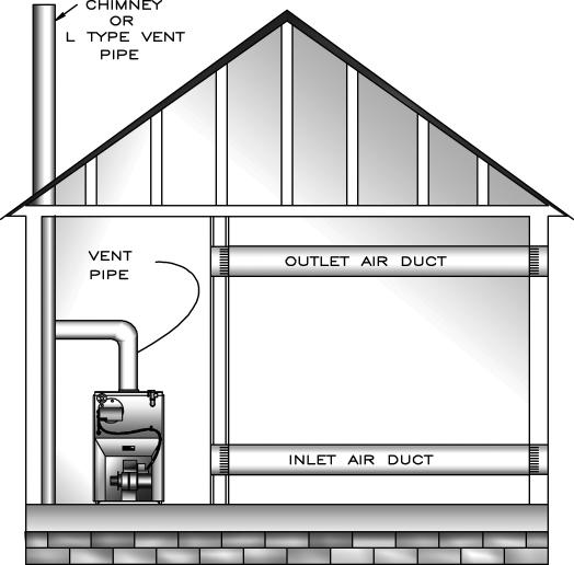
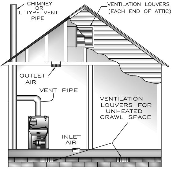
7 VENTILATION & COMBUSTION AIR 4. When air for combustion and room ventilation is from inside buildings, confined space shall be provided with two permanent openings, one starting 12 inches from the top and one 12 inches from the bottom of the enclosed space. Each opening shall have a minimum free area of 1 square inch per one thousand (1,000) Btu per hour of the total input rating of all appliances in the enclosed space, but must not be less than one hundred (100) square inches. These openings must freely communicate with the interior areas having adequate infiltration from the outside. See Figure #1. 5. When the boiler is installed in a confined space and all air is provided from the outdoors, the confined space shall be provided with two permanent openings, one commencing within 12 inches from the top and one commencing 12 inches from the bottom of the enclosure. The openings shall communicate directly, or by ducts, with the outdoors or spaces (crawl or attic) that freely communicate with the outdoors. One of the following methods must be used to provide adequate air for ventilation and combustion. A. When directly communicating with the outdoors, each opening shall have a minimum free area of 1 square inch per 4,000 Btu per hour of total input rating of all equipment in the enclosure. See Figure #2. B. When communicating with the outdoors by means of vertical ducts, each opening shall have a minimum free area 1 square inch per 4,000 Btu per hour of total input rating of all appliances in the enclosed space. See Figure #3. C. If horizontal ducts are used, each opening shall have a minimum free area 1 square inch per 2,000 Btu per hour total input rating of all appliances in the enclosed space. See Figure #4. D. When ducts are used, they shall be of the same cross sectional area as the free area of the area of the openings to which they connect. The minimum dimension of rectangular air ducts shall not be less than 3 inches. 6. In calculating free area using louvers, grills or screens for the above, consideration shall be given to their blocking effect. Screens used shall not be smaller than ¼ inch mesh. If the free area through a design of louver or grill is known, it should be used in calculating the size opening required to provide the free area specified. If the design and free area is not known, it may be assumed that wood louvers will have 20-25% free area and metal louvers and grills will have 60-75% free area. Louvers and grills shall be fixed in the open position or interlocked with the boiler so that they are opened automatically during boiler operation. Refer to the Combustion Air Requirements chart on previous page for combustion air minimum opening requirements. Figure #1 7

8 VENTILATION & COMBUSTION AIR Figure #2 Figure #3 Figure #4 8
9 CONNECTING SUPPLY AND RETURN PIPING 1. Connect supply and return piping as suggested in Figure #5, below. When boiler is used in connection with refrigerated systems: A. Chilled medium MUST BE IN PARALLEL with boiler. B. Use appropriate valves to prevent chilled medium from entering heating boiler. 2. During heating cycle open valves A and B, close valves C and D. 3. During heating cooling cycle open valves C and D, close valves A and B. A. Maintain minimum clearance of one inch to hot water pipes. In air handling units where they may be exposed to refrigerated air circulation, boiler piping system MUST be supplied with flow control valves or other automatic means to prevent gravity circulation of boiler water during cooling cycle. 4. Hot water boilers installed above radiation level must be provided with low water device either as part of boiler or at time of boiler installation. 5. When boiler is connected to heating system utilizing multiple zoned circulators, each circulator must be supplied with flow control valve to prevent gravity circulation. * Reduced pressure back flow preventer must be used under provisions required by the Environmental Protection Agency, (EPA). 6. Bypass piping is an option which gives ability to adjust supply boiler water temperature to fit system or condition of installation. Although, this method of piping is not typically required for baseboard heating systems. Figure #5 9
10 CONNECTING SUPPLY AND RETURN PIPING A. This method is used to protect boilers from condensate forming due to low temperature return water. Generally noticed in large converted gravity systems or other large water volume systems. See Figure #6. B. These methods are used to protect systems using radiant panels and material they are encased in from high temperature supply water from boiler and protect boiler from condensation. See Figures #7 and #8 following page. C. This method is used to protect boilers from condensate forming as well as protecting heating system from high water temperature. See Figure #8 following page. Note: When using bypass piping, adjust valves A and B until desired system temperature is obtained. 7. Bypass loop piping must be same size piping for supply and return. Figure #6 Bypass Piping 10
11 Figure #7 - Mixing Valve Piping CONNECTING SUPPLY AND RETURN PIPING Figure #8 - Primary Secondary Piping With Bypass 11
12 8. Typical installation using circulators is shown in Figure #9. 9. Typical installation using zone valves is shown in Figure #10. CONNECTING SUPPLY AND RETURN PIPING Figure #9 - Primary Secondary Piping With Bypass Figure #10 - Primary Secondary Piping With Bypass 12

13 SYSTEM PIPING! WARNING Burn or Scald Hazard. Discharge line shall be installed to relief valve outlet connection to avoid burns, scalding, or water damage due to discharge of steam and/or hot water during operation. Discharge line shall: Connect to safety valve outlet. Piped down to safe point of disposal. Check local codes for maximum distance from floor or allowable safe point of discharge. Pipe size be of equal to or greater than of safety valve outlet over entire length of discharge line. Have no intervening shutoff valve between safety valve and discharge to atmosphere. Do not plug or place any obstruction in discharge line. Terminate freely to atmosphere where any discharge will be clearly visible and at no risk of freezing. Allow complete drainage of valve and discharge line. Install safety valve with spindle in vertical position. Do not install shutoff valve between boiler and safety valve. Support safety valve discharge piping. Be short and straight as possible. Terminate with plain end, not threaded. Constructed of material suitable for exposure to temperatures of 375 F (191 C); or greater. Refer to local codes and appropriate ASME Boiler and Pressure Vessel Code for additional installation requirements. 10. Install discharge piping from safety relief valve. Use ¾ or larger pipe. See Figure #11. Individual boiler discharge piping shall be independent of other discharge piping. Size and arrange discharge piping to avoid reducing safety relief valve relieving capacity below minimum relief valve capacity stated on rating plate. Install union, if used, close to safety relief valve outlet. Install elbow(s), if used, close to safety relief valve outlet and downstream of union (if used). Figure #11 - Discharge Piping From Safety Relief Valve SAFETY RELIEF VALVE DISCHARGE PIPING Check local codes for maximum distance from floor or allowable safe point of discharge. 13
14 CONNECTING SUPPLY AND RETURN PIPING Figure #12 - Recommended Piping For Boilers Equipped With T3 Or T4 Tankless Heater! DANGER Water temperatures exceeding 125 F will cause severe burns instantly or death by scalding. Automatic mixing valve must be installed on outlet of domestic coil. Installation must comply with valve manufacturer s recommendations, and instructions. Do not remove bolts or limit at time of installation. Pipe in accordance with boiler s Installation, Operation and Maintenance Manual. Due to varying water conditions, adjustable flow restricter must be installed in cold water inlet of this coil. 14

15 CONNECTING SUPPLY AND RETURN PIPING OPTIONS UTILIZING 3/4 TAPPING Figure #13 - Optional Location For Air Vent Figure #14 - Optional Location For Expansion Tank (Non-Diaphragm Type) 15
16 VENTING SYSTEM INSPECTION & INSTALLATION INSPECT CHIMNEY to make certain it is constructed according to latest revision of the NFPA 211. Local codes may differ from this code and should be checked. Where there is a conflict, local code will prevail. Boiler must be installed into chimney which has masonry or metallic chimney liner. Unlined chimney will have leaks that will cause poor chimney performance (NO DRAFT), and could result in poor positive pressure in combustion chamber. Horizontal portions of venting system should not exceed 10 feet in length. Horizontal lengths over 10 feet will have negative effect on chimney performance. Chimney should extend at least 2 feet above any portion of building within 10 feet. See Figure #15. It should produce negative draft of.06 to.08 inches of water column, (W.C.), as measured with draft gauge between boiler and barometric draft control while maintaining.02 inch W.C. negative draft in combustion chamber. See chart Chimney or Vent Sizes for recommended chimney or vent sizes. Inadequate draft will cause improper combustion, resulting in dirty flue ways and high fuel bills. Figure #15 CONNECT FLUE PIPE same size as boiler outlet to chimney, sloping upward continuously toward chimney approximately ¼ per foot. Bolt or screw joints together to avoid sag. If oil fired water heater is vented into same flue as boiler, provide separate hole into chimney whenever possible. When not possible, use Y connection in flue pipe, using separate draft regulator for each unit. When chimney will not provide adequate draft to handle input from water heater and boiler simultaneously, wire units so that only one will operate at a time, favoring water heater. 16
17 OIL TANK AND PIPING Install burner per instructions provided with burner-ina-box kit. Install oil tank and piping in accordance with the National Board of Fire Underwriters and local regulations. Oil storage tank, vent, fill pipe and caps should be as prescribed by local codes. In no case should vent pipe be smaller than 1¼ I.P.S. Fill pipe should not be less than 2 I.P.S. Suction line from tank to burner should be one continuous piece of tubing to prevent air entering line. Suction line, must be ⅜ O.D. copper tubing for runs of 50 feet or less, and ½ O.D. for longer runs. Oil return line, same size as suction line, must be used on any installation where bottom of tank is below fuel unit of burner. Oil lines should be buried or otherwise protected from mechanical injury. Flare fittings on all oil lines are recommended. Compression fittings on suction line often allow air to be drawn into fuel pump, making it difficult to maintain oil pressure at nozzle. Do not run overhead fuel lines from tank to oil burner. Fuel pump connections and by-pass should be made according to instructions attached to fuel pump. If tank is more than 20 from boiler, a two stage fuel unit should be installed in place of single stage pump supplied as standard equipment with burner. Make certain rotation and speed are same and pump is suitable for burner horsepower rating. Oil line filter and shut-off valve should be installed in suction line. Shut-off valves should be installed in both suction and return lines at burner for convenience in servicing burner. Allow extra tubing at burner so burner may be removed from boiler for cleaning without disconnecting tubing. (See Figures #16 & #17, below). Optional flexible oil line is available. Figure #16 - Typical Installation Single Pipe Oil System Figure #17 - Typical Installation Two Pipe Oil System 17
18 ELECTRICAL WIRING! WARNING Electrical shock hazard. Turn OFF electrical power supply at service panel before making electrical connections. Failure to do so could result in death or serious injury. Electrically bond boiler to ground in accordance with requirements of authority having jurisdiction. Refer to: USA- National Electrical Code, ANSI/NFPA 70. Install fused disconnect switch between boiler and meter at convenient location. Sequence Of Operations On call for heat, thermostat will actuate, completing circuit to limit. In turn, circulator and ignition systems are activated and ignition will begin. In event boiler water temperature exceeds high limit setting on boiler mounted limit, power will be interrupted between limit and ignition system. Power will remain off until boiler water temperature drops below high limit setting. Circulator will continue to operate under this condition until thermostat is satisfied. Thermostat Installation 1. Thermostat should be installed on inside wall about four feet above the floor. 2. NEVER install thermostat on outside wall. 3. Do not install thermostat where it will be affected by: Drafts Hot or cold pipes Sun light Lighting fixtures Television sets Fireplace or chimney 4. Check thermostat operation by raising and lowering thermostat as required to start and stop burner. 5. Instructions for final adjustment of thermostat are packaged with thermostat ( adjusting heating anticipator, calibration, ect.). 18
19 ELECTRICAL WIRING Figure #18 - Wiring Diagram Beckett AFG without Tankless Heater Figure #19 Wiring Diagram Beckett AFG wth Tankless Heater 19
20 OPERATING INSTRUCTIONS Operating Instructions 1. Inspect venting system at start of each heating season. 2. Check vent pipe from boiler to chimney for signs of deterioration by rust or sagging joints. Repair if necessary. 3. Remove vent pipe at base of chimney or flue and, using mirror, check for obstruction. Safety Relief Valve! WARNING Burn and scald hazard. Safety relief valve could discharge steam or hot water during operation. Operate lever of safety relief valve, on boiler periodically to make sure it is functioning properly. Safety relief valve should open before water pressure exceeds 30 psi. reading on gauge. If this pressure is exceeded and safety relief valve leaks water when boiler is operating at normal pressures, it should be immediately replaced. Corrosion can build up rapidly at valve seat and prevent its functioning as safety device. See Figure #11, page 13. Start-Up And Adjustment Of Oil Burner (See oil burner instructions for nozzle and electrode setting) A. Check oil burner nozzle to make certain it is tight in adapter. Burner mounting bolts should be tight. B. Check electrode setting, they may have been jarred out of position during transportation. C. Lubricate burner motor and circulator motor if required. Some circulators are water lubricated and do not require oiling. D. Set room thermostat to call for heat, or jump thermostat contacts on the boiler control. E. Open all oil line valves. F. Turn service switch on. Burner should start. G. On one pipe fuel systems only, vent pump as soon as burner starts. Allow oil to run until all traces of air in the suction line disappear. H. Turn OFF burner and install pressure gauge port on pump. I. Start burner again and check oil pressure for 140 psi.. Adjust if necessary. Do not set fire visually. Instruments are only reliable method to determine proper air adjustments. Improperly adjusted burner causes soot and high fuel bills because of incomplete combustion of fuel oil. This in turn may require excessive boiler maintenance, service costs, and in some instances, house cleaning or redecorating. A competent service mechanic should be consulted to make proper adjustments with smoke tester, CO 2 indicator and draft gauge. Bacharach or Dwyer test kits include these instruments. Instructions For Proper Operation Of Boiler Burner Unit A ¼ diameter slot is provided in inspection cover plate to take draft readings in combustion chamber. See Figure #20. A ¼ diameter hole will be required in flue pipe between boiler and barometric damper (if used) to take draft, CO 2, smoke and temperature readings. Adjust air shutter on oil burner to obtain trace of smoke. Measure CO 2 at this point. Increase air adjustment to lower CO 2 approximately one (1) percent. Check to insure minimum negative.02 w.c., (water column), overfire draft and zero (0) smoke. If -.02 w.c. overfire draft can not be maintained, changes and/or modifications may be required in venting or chimney. Following table (page 21) is provided as guideline for initial start-up. Final adjustments MUST be made using combustion instruments as previously mentioned. Check Safety Control Circuit - after burner adjustments have been made for satisfactory performance. 1. High limit control: remove cover and note temperature setting. See Figure #20. With burner operating, decrease setting to minimum point. When boiler water temperature exceeds this set point, high limit switch will open, shutting off power to oil burner. Return setting to desired high limit point. Burner should restart. Refer to instructions included with limit. 2. Primary control and flame sensor check following: A. Flame failure - simulate by shutting off oil supply with hand valve while burner is on. Sixty seconds after flameout, the safety switch locks out, ignition stops, motor stops and oil valve - when used - closes. To restart, open oil supply valve and reset safety switch. B. Ignition failure - with burner off, close oil supply valve and run through start-up procedure, The safety switch should lock out as in flame failure. 20
21 OPERATING INSTRUCTIONS C. Power failure - Turn off main power supply switch while burner is operating. When burner stops, restore power and burner should start. If operation is not as described as above, check wiring and controls. Preventive Maintenance - of oil fired boiler reduces operating costs. Boiler and vent pipe should be inspected for accumulation of soot or scale deposits periodically but at least once every year before start of each heating season. When soot is present on section walls and flueways, improper combustion will result, causing additional sooting and scaling until flueways are completely closed. To remove soot and scale from flueways, remove top jacket panel, top clean-out plate, open burner swing door. See figure #20. Periodic Inspection - and tightening of tankless heater/ cover plate bolts will reduce risk of leaks. See Replacement Parts Heat Exchanger section. Instructions For Opening Burner Swing Door 1. Turn off power to boiler. 2. Allow boiler to cool down. 3. Disconnect power cable at factory supplied burner electrical disconnect. See Figure #20.! WARNING Burn, scald hazard. Do not attempt to start the burner when excess oil has accumulated, when the unit is full of vapor, or when the combustion chamber is very hot. 4. Loosen screws on the sides of lower front jacket panel. See Figure # Pull bottom part of lower front panel forward. 6. Lift lower front panel up and off boiler. See Figure # Close oil valve. See Figures #16 & # Disconnect oil line from burner. 9. Do not try to swing door with oil line attached. 10. Remove nut from swing door stud on right hand side of door. 11. Swing open burner and door to the left. Brush, using flue brush, soot and scale into combustion space where it can be removed through swing door opening. It is recommended to replace nozzle at start of each heating season. Lubricate burner motor and circulator motor - if required - with few drops of good grade light motor oil. Do not over oil. Have service agent service burner, check controls and check electrodes for carbon or cracks in insulators. Burners should be adjusted to produce conditions shown in Start-up and Adjustment of Oil Burner procedure covered earlier in this section. Use caution when vacuuming in the chamber area. Damage to chamber could result. NOTICE Use only number 2 fuel oil. Do not use gasoline, crankcase drainings or any oil containing gasoline. 21
22 OPERATING INSTRUCTIONS BOILER NO. HEAD TYPE HEAD SETTING BECKETT AFG SETTINGS STATIC PLATE NOZZLE PUMP PRESSURE [PSI] AIR BAND AIR SHUTTER SFH-3085W L1 -- 3⅜ B SFH-3100W L1 -- 3⅜ B SFH-4100W V1 0 2¾ B SFH-4125W V1 0 2¾ B SFH-4145W V1 2 2¾ B SFH-5160W F ¾ B SFH-5185W F ¾ B SFH-6175W F B SFH-6210W F B
23 OPERATING INSTRUCTIONS Figure #20 Instructions For Closing Burner Swing Door 1. Swing burner and door to right until insulation is slightly compressed and stud is exposed. 2. Attach nut to stud and tighten until built in stop contacts the mounting door. 3. Replace oil line to burner. 4. Replace lower jacket panel, and tighten screws. 5. Connect power cable at factory supplied burner electrical disconnect. 6. Turn on power to boiler. 7. Bleed oil line. 23
24 UTICA BOILERS 2201 Dwyer Avenue Utica NY web site:
STARFIRE IV SERIES 4 WATER OIL FIRED CAST IRON BOILER
 Models SFH-3085 SFH-3100 SFH-4100 SFH-4125 SFH-4145 SFH-5160 SFH-5185 SFH-6175 SFH-6210 STARFIRE IV SERIES 4 WATER OIL FIRED CAST IRON BOILER INSTALLATION, OPERATION & MAINTENANCE MANUAL Tested For 75
BC Series II OIL-FIRED CAST IRON BOILER INSTALLATION, OPERATION & MAINTENANCE MANUAL FOR US AND CANADIAN SALES
 Models BC3095 BC4100 BC4115 BC Series II OIL-FIRED CAST IRON BOILER INSTALLATION, OPERATION & MAINTENANCE MANUAL FOR US AND CANADIAN SALES Maximum Allowable Working Pressure 30 psi. Manufactured by: ECR
ESC IV STEAM SERIES 4 OIL-FIRED CAST IRON BOILER
 ESC IV STEAM SERIES 4 OIL-FIRED CAST IRON BOILER MODELS ESC-3090S ESC-3090ST ESC-4125S ESC-4125ST ESC-5185S ESC-5185ST ESC-6210S ESC-6210ST INSTALLATION, OPERATION & MAINTENANCE MANUAL PATENT 7,823,544
STARFIRE V STEAM Series 5 OIL-FIRED CAST IRON BOILER INSTALLATION, OPERATION & MAINTENANCE MANUAL. Models
 STARFIRE V STEAM Series 5 OIL-FIRED CAST IRON BOILER INSTALLATION, OPERATION & MAINTENANCE MANUAL Models SFE-3090S SFE-3090ST SFE-4125S SFE-4125ST SFE-5185S SFE-5185ST SFE-6210S SFE-6210ST PATENT 7,823,544
SERIES II OIL-FIRED CAST IRON HOT WATER BOILER
 Model No. UH3KW0.60 UH3KW0.75 UH3KW1.00 UH4KW0.90 UH4KW1.25 UH4KW1.50 UH5KW1.20 UH5KW1.75 UH5KW2.00 SERIES II OIL-FIRED CAST IRON HOT WATER BOILER INSTALLATION, OPERATION & MAINTENANCE MANUAL Manufactured
INSTALLATION MANUAL AND OPERATING INSTRUCTIONS
 INSTALLATION MANUAL AND OPERATING INSTRUCTIONS MODEL NUMBERS: KSB0365, KSB3100, KSB4125, KSB4150, KSB5175, KSB5200, KSB6225, KSB7275 PENNCO BOILERS 85 Middle Rd. Dunkirk, NY 14048 Ph: (716) 366-5500 Fax:
High Efficiency 3-Pass Oil Fired Hot Water Boiler
 FOR U.S. SALES ONLY This manual must be left with owner and should be hung on or adjacent to the boiler for reference. Q3 US High Efficiency 3-Pass Oil Fired Hot Water Boiler MODELS Q3-4, Q3-5, Q3-6 and
INSTALLATION INSTRUCTIONS
 PRODUCT LITERATURE Lennox Industries Inc. Dallas, Texas INSTALLATION INSTRUCTIONS COWB3 OIL FIRED BOILER RETAIN THESE INSTRUCTIONS FOR FUTURE REFERENCE These instructions must be affixed on or adjacent
Do not use this vent pipe or fittings for venting incinerators of any kind.
 ! CAUTION! Do not use this vent pipe or fittings for venting incinerators of any kind. C.S.A. Certified For Natural Gas Or Propane Tested For 100 LBS. ASME Working Pressure For correct installation of
USER'S INFORMATION MANUAL
 USER'S INFORMATION MANUAL SERIES DV GAS FIRED HOT WATER HEATING BOILER WARNING: If the information in this manual is not followed exactly, a fire or explosion may result causing property damage, personal
Models TRB4075 TRB4095 TRB4110 TRB5100 TRB5115 TRB5135 TRB6130 TRB6145 TRB6165 TRB7165 TRB7180 TRB7190
 II Models TRB4075 TRB4095 TRB4110 TRB5100 TRB5115 TRB5135 TRB6130 TRB6145 TRB6165 TRB7165 TRB7180 TRB7190 An ISO 9001-2008 Certified Company 2201 Dwyer Avenue, Utica NY 13501 web site: www.ecrinternational.com
USER'S INFORMATION MANUAL
 USER'S INFORMATION MANUAL SERIES ODVB GAS FIRED HOT WATER HEATING BOILER WARNING: If the information in this manual is not followed exactly, a fire or explosion may result causing property damage, personal
DXL SERIES II CAST IRON GAS FIRED BOILERS FOR FORCED HOT WATER. Models INSTALLATION, OPERATION & MAINTENANCE MANUAL
 DXL SERIES II Models DXL-50 DXL-75 DXL-100 DXL-125 DXL-150 DXL-170 DXL-200 CAST IRON GAS FIRED BOILERS FOR FORCED HOT WATER INSTALLATION, OPERATION & MAINTENANCE MANUAL Tested For 100 psi. ASME Working
FOR FORCED HOT WATER MODEL NUMBERS: 15045, 15070, 15096, 15120, 15145, 15175, 15195, 15245, 15295
 FOR FORCED HOT WATER MODEL NUMBERS: 5045, 5070, 5096, 520, 545, 575, 595, 5245, 5295 PENNCO BOILERS 85 Middle Rd. Dunkirk, NY 4048 www.ecrinternational.com An ISO 900-2000 Certified Company P/N 305026,
JD Series Cast Iron Commercial Hot Water or Steam Boiler
 JD Series Cast Iron Commercial Hot Water or Steam Boiler INSTALLATION, OPERATION & MAINTENANCE MANUAL An ISO 9001-2008 Certified Company Utica Boilers 2201 Dwyer Ave. Utica, NY 13501 Phone: (315) 797-1310
USER'S INFORMATION MANUAL
 USER'S INFORMATION MANUAL CAST IRON GAS FIRED WATER HEATING BOILERS WARNING: If the information in this manual is not followed exactly, a fire or explosion may result causing property damage, personal
DOMESTIC WATER HEATER OIL FIRED
 DOMESTIC WATER HEATER OIL FIRED Models : CMO32-II CMO32-II-R CMO50-II CMO32-II & CMO32-II-R INSTALLER / SERVICE TECHNICIAN: USE THE INFORMATION IN THIS MANUAL FOR THE INSTALLATION AND SERVICING OF THE
AFUE up to 85.2% Heating Input 105,000 to 245,000 Btuh
 WATER HEATERS / BOILERS COWB3 Oil-Fired Hot Water Boiler PRODUCT SPECIFICATIONS Bulletin No. 0654 March 08 Supersedes September 05 AFUE up to 85.% Heating Input 05,000 to 45,000 Btuh MODEL NUMBER IDENTIFICATION
Internet Version for Reference Only INDUCED DRAFT COMMERCIAL WATER HEATERS SUPPLEMENT INSTRUCTIONS TO PART #
 INDUCED DRAFT COMMERCIAL WATER HEATERS SUPPLEMENT INSTRUCTIONS TO PART #238-39387-00 THIS INSTRUCTION SUPPLEMENT IS ONLY INTENDED TO GIVE INSTALLATION INSTRUCTIONS AND INFORMATION RELATED TO THE INDUCED
Crown Boiler Company
 Crown Boiler Company Oil Vent Damper Supplemental Installation Instructions Converts Select TWZ Series Boilers to High Efficiency TWD Series Boilers These supplemental installation instructions are to
GENERAL BASIC INSTALLATION INSTRUCTIONS DIRECT FIRED HOT WATER BOILERS PARKER BOILER CO.
 GENERAL BASIC INSTALLATION INSTRUCTIONS DIRECT FIRED HOT WATER BOILERS PARKER BOILER CO. GBI 201-5 3C For a proper installation and in order to receive the best in operating life and efficiency from your
Fully-automatic Gas tankless Water Heater USER'S MANUAL FOR MODEL EZ-101 ISO9001 certified
 Fully-automatic Gas tankless Water Heater USER'S MANUAL FOR MODEL EZ-101 ISO9001 certified Thank you for purchasing our fully-automatic gas-fired tankless water heater. Please completely read this Manual
Oil-Fired Hot Water Boilers Installation Instructions These instructions must be affixed on or adjacent to the boiler
 D E S I G N E D T O L E A D FWZ Series Oil-Fired Hot Water Boilers Installation Instructions These instructions must be affixed on or adjacent to the boiler Models: FWZ060 FWZ080 FWZ100 FWZ130 FWZ160 Warning:
15B SERIES II. Models 15B045FE 15B070FE 15B096FE 15B120FE 15B145FE 15B170FE 15B195FE 15B245FE 15B295FE
 15B SERIES II Models 15B045FE 15B070FE 15B096FE 15B120FE 15B145FE 15B170FE 15B195FE 15B245FE 15B295FE Cast Iron Gas Fired Boilers For Forced Hot Water INSTALLATION, OPERATION & MAINTENANCE MANUAL An ISO
DVB SERIES Gas Fired Boilers For Forced Hot Water
 DVB SERIES Gas Fired Boilers For Forced Hot Water INSTALLATION, OPERATION & MAINTENANCE MANUAL An ISO 9001-2008 Certified Company 2201 Dwyer Avenue Utica New York 13504 USA www.ecrinternational.com P/N
15B SERIES Cast Iron Gas Fired Boilers For Forced Hot Water
 5B SERIES Cast Iron Gas Fired Boilers For Forced Hot Water MODEL NUMBERS: 5B045, 5B070, 5B096, 5B20, 5B45, 5B75, 5B95, 5B245, 5B295 INSTALLATION, OPERATION & MAINTENANCE MANUAL An ISO 900-2000 Certified
15B SERIES Cast Iron Gas Fired Boilers For Forced Hot Water
 5B SERIES Cast Iron Gas Fired Boilers For Forced Hot Water MODEL NUMBERS: 5B045, 5B070, 5B096, 5B20, 5B45, 5B75, 5B95, 5B245, 5B295 INSTALLATION, OPERATION & MAINTANANCE MANUAL An ISO 900-2000 Certified
WPSB SERIES II GAS-FIRED HOT WATER BOILERS
 Models WPSB-3D WPSB-3DP WPSB-4D WPSB-4DP WPSB-5D WPSB-5DP WPSB-6D WPSB-6DP WPSB-7D WPSB-7DP WPSB-8D WPSB-8DP WPSB-9D WPSB-9DP WPSB SERIES II GAS-FIRED HOT WATER BOILERS Tested For 50 psi. ASME Working
INSTALLATION INSTRUCTIONS
 2012 Lennox Industries Inc. Dallas, Texas, USA INSTALLATION INSTRUCTIONS ELO183B SERIES UNITS Front Flue Model Shown RETAIN THESE INSTRUCTIONS FOR FUTURE REFERENCE IMPORTANT This unit must be serviced
CMO32 CMO50 DOMESTIC WATER HEATER OIL-FIRED. Models: CMO32 CMO50
 DOMESTIC WATER HEATER OIL-FIRED Models: CMO32 CMO50 DNS-1102 Rev. A DNS-0413 Rev. A CMO32 CMO50 INSTALLER / SERVICE TECHNICIAN: USE THE INFORMATION IN THIS MANUAL FOR THE INSTALLATION AND SERVICING OF
OWNERS MANUAL MODEL DO110 & DO180 IS CERTIFIED TO: Unit Serial # Purchased From Company Address
 OWNERS MANUAL MODEL DO110 & DO180 IS CERTIFIED TO: UL 391 CAN/CSA B366.1 Unit Serial # Purchased From Company Address Name of Installer Installer Telephone # Date Installed IMPORTANT This manual must be
15B SERIES II. Models 15B045FE 15B070FE 15B096FE 15B120FE 15B145FE 15B170FE 15B195FE 15B245FE 15B295FE
 15B SERIES II Models 15B045FE 15B070FE 15B096FE 15B120FE 15B145FE 15B170FE 15B195FE 15B245FE 15B295FE Cast Iron Gas Fired Boilers For Forced Hot Water INSTALLATION, OPERATION & MAINTENANCE MANUAL An ISO
WPSB SERIES II. Models WPSB-3D WPSB-3DP WPSB-4D WPSB-4DP WPSB-5D WPSB-5DP WPSB-6D WPSB-6DP WPSB-7D WPSB-7DP WPSB-8D WPSB-8DP WPSB-9D WPSB-9DP
 Models WPSB-3D WPSB-3DP WPSB-4D WPSB-4DP WPSB-5D WPSB-5DP WPSB-6D WPSB-6DP WPSB-7D WPSB-7DP WPSB-8D WPSB-8DP WPSB-9D WPSB-9DP WPSB SERIES II GAS-FIRED HOT WATER BOILERS INSTALLATION, OPERATION & MAINTENANCE
INSTALLATION INSTRUCTIONS
 2015 Lennox Industries Inc. Dallas, Texas, USA INSTALLATION INSTRUCTIONS ELO183B SERIES UNITS Front Flue Model Shown RETAIN THESE INSTRUCTIONS FOR FUTURE REFERENCE IMPORTANT This unit must be serviced
MGB CAST IRON GAS FIRED BOILERS FOR FORCED HOT WATER. Models MGB-50J MGB-75J MGB-100J MGB-125J MGB-150J MGB-170J MGB-200J
 Models MGB-50J MGB-75J MGB-100J MGB-125J MGB-150J MGB-170J MGB-200J MGB CAST IRON GAS FIRED BOILERS FOR FORCED HOT WATER INSTALLATION, OPERATION & MAINTENANCE MANUAL C.S.A. Certified For Natural Gas Or
USER'S INFORMATION MANUAL
 USER'S INFORMATION MANUAL WARNING: If the information in this manual is not followed exactly, a fire or explosion may result causing property damage, personal injury or loss of life. Do not store or use
GENERAL BASIC INSTALLATION INSTRUCTIONS INDIRECT GAS FIRED WATER HEATERS PARKER BOILER CO.
 GENERAL BASIC INSTALLATION INSTRUCTIONS INDIRECT GAS FIRED WATER HEATERS PARKER BOILER CO. GBI 210 3C For a proper installation and in order to receive the best in operating life and efficiency from your
GAS FIRED BOILERS FOR FORCED HOT WATER VENTING ADDENDUM. ECR International Ltd. - Olsen Division P.O. Box 900 Wallaceburg, Ont.
 ODV-B GAS FIRED BOILERS FOR FORCED HOT WATER VENTING ADDENDUM ECR International Ltd. - Olsen Division P.O. Box 900 Wallaceburg, Ont. N8A5E5 TABLE OF CONTENTS HORIZONTAL PIPING... PAGES 1-10 WARNINGS...
DXL SERIES II. Models CAST IRON GAS FIRED BOILERS FOR FORCED HOT WATER INSTALLATION, OPERATION & MAINTENANCE MANUAL
 Models DXL-50 DXL-75 DXL-100 DXL-125 DXL-150 DXL-170 DXL-200 DXL SERIES II CAST IRON GAS FIRED BOILERS FOR FORCED HOT WATER INSTALLATION, OPERATION & MAINTENANCE MANUAL Tested For 100 psi. ASME Working
OIL FIRED WARM AIR FURNACE. Homeowner Instructions
 OIL FIRED WARM AIR FURNACE Homeowner Instructions Fire, explosion, asphyxiation and electrical shock hazard. Improper installation and operation could result in death or serious injury. Read this manual
MGB CAST IRON GAS FIRED BOILERS FOR FORCED HOT WATER With Hydrolevel Control. Models MGB-50J MGB-75J MGB-100J MGB-125J MGB-150J MGB-170J MGB-200J
 Models MGB-50J MGB-75J MGB-100J MGB-125J MGB-150J MGB-170J MGB-200J MGB CAST IRON GAS FIRED BOILERS FOR FORCED HOT WATER With Hydrolevel Control INSTALLATION, OPERATION & MAINTENANCE MANUAL C.S.A. Certified
SERIES 24. Series 24 Features. Commercial, Forced Draft, Hot Water or Steam Boiler. The right fit for any commercial job
 SERIES Commercial, Forced Draft, Hot Water or Steam Boiler Sizes from to,8 MBH output The right fit for any commercial job The Series is built to handle any installation - businesses, institutions, apartments,
User s Information Manual Models: 45, ,000 Btu/hr
 SBR-USER_100161678_2000017137_Rev C User s Information Manual Models: 45,000-260,000 Btu/hr If the information in this manual is not followed exactly, a fire or explosion may result causing property damage,
INSTALLATION AND OPERATION MANUAL FOR 2 STAGE RIELLO BURNER ADDENDUM TO ( Mo 437 manual )
") INSTALLATION AND OPERATION MANUAL FOR 2 STAGE RIELLO BURNER ADDENDUM TO ( Mo 437 manual ) FOR USE WITH MODEL: OH6FX072DV4 PLEASE READ THESE INSTRUCTIONS PRIOR TO INSTALLATION, INITIAL FIRING, AND BEFORE
INSTALLATION AND OPERATION MANUAL FOR 2 STAGE RIELLO BURNER ADDENDUM TO ( Mo 437 manual ) FOR USE WITH MODEL: OH6FX072DV4 PLEASE READ THESE INSTRUCTIONS PRIOR TO INSTALLATION, INITIAL FIRING, AND BEFORE
POWER VENTER SYSTEM. Model: PVO-300, PVO-600
 POWER VENTER SYSTEM Model: PVO-300, PVO-600 Included is one ETL and cetl listed Power Venter to be used primarily with a single 120VAC controlled oil fired furnace, boiler, or water heater. The PVO may
USER'S INFORMATION MANUAL
 USER'S INFORMATION MANUAL WARNING: If the information in this manual is not followed exactly, a fire or explosion may result causing property damage, personal injury or loss of life. Do not store or use
GAS-FIRED STEAM BOILERS. Models PEG075DID PEG112DID PEG150DID PEG187DID PEG225DID PEG262DID PEG299DID INSTALLATION, OPERATION & MAINTENANCE MANUAL
 GAS-FIRED STEAM BOILERS Models PEG075DID PEG112DID PEG150DID PEG187DID PEG225DID PEG262DID PEG299DID INSTALLATION, OPERATION & MAINTENANCE MANUAL MODEL PEGDID Electronic Intermittent Ignition An ISO 9001-2008
INSTALLATION, OPERATING AND SERVICE INSTRUCTIONS CL SERIES CAST IRON OIL-FIRED BOILER
 INSTALLATION, OPERATING AND SERVICE INSTRUCTIONS CL SERIES CAST IRON OIL-FIRED BOILER 9700609 For service or repairs to boiler, call your heating contractor. When seeking information on boiler, provide
Oil-Fired Steam Boilers INSTALLATION INSTRUCTIONS These instructions must be affixed on or adjacent to the boiler WARNING
 D E S I G N E D T O L E A D FSZ Series Oil-Fired Steam Boilers INSTALLATION INSTRUCTIONS These instructions must be affixed on or adjacent to the boiler WARNING Improper installation, adjustment, alteration,
OPERATING INSTRUCTIONS MANUAL (Please retain for future reference) FVO-200 INDIRECT FIRED SPACE HEATERS
 FVO-200 INDIRECT FIRED SPACE HEATERS") OPERATING INSTRUCTIONS MANUAL (Please retain for future reference) For FVO-200 INDIRECT FIRED SPACE HEATERS CERTIFIED FOR USE IN CANADA AND U.S.A. As per CSA B140.8 Portable Oil Fired Heaters / CSA B140.02003
OPERATING INSTRUCTIONS MANUAL (Please retain for future reference) For FVO-200 INDIRECT FIRED SPACE HEATERS CERTIFIED FOR USE IN CANADA AND U.S.A. As per CSA B140.8 Portable Oil Fired Heaters / CSA B140.02003
UH16 Series Gas Fired Steam Boilers
 UH16 Series Gas Fired Steam Boilers Models UH1603HSID UH1604HSID UH1605HSID UH1606HSID UH1607HSID UH1608HSID UH1609HSID INSTALLATION, OPERATION & MAINTENANCE MANUAL MODEL HSID Electronic Intermittent Ignition
MGC GAS-FIRED HOT WATER BOILERS. Models MGC-8D MGC-8DP MGC-9D MGC-9DP INSTALLATION, OPERATION & MAINTENANCE MANUAL
 Models MGC-8D MGC-8DP MGC-9D MGC-9DP MGC GAS-FIRED HOT WATER BOILERS INSTALLATION, OPERATION & MAINTENANCE MANUAL C.S.A. Certified for Natural gas or Propane Tested for 50 psi. ASME Working Pressure Manufactured
USER'S INFORMATION MANUAL
 USER'S INFORMATION MANUAL SERIES JD GAS FIRED STEAM AND HOT WATER HEATING BOILER : If the information in this manual is not followed exactly, a fire or explosion may result causing property damage, personal
INSTALLATION AND SERVICE MANUAL. Hot Water Heating Boilers Domestic Hot Water Supply Boilers 399, ,000 Btu/hr Models
 INSTALLATION AND SERVICE MANUAL CF/CH(P)i&S-02 Hot Water Heating Boilers Domestic Hot Water Supply Boilers 399,999 750,000 Btu/hr Models Installation and service must be performed by a qualified service
Boiler Manual. Series 3 Oil-Fired Water Boiler. Maintenance Parts. Installation Startup
 Series 3 Oil-Fired Water Boiler Boiler Manual Installation Startup Maintenance Parts This manual must only be used by a qualified heating installer/service technician. Read all instructions, including
Oil-Fired Water Heater
 Oil-Fired Water Heater INSTALLATION MANUAL NOTICE: HTP reserves the right to make product changes or updates without notice and will not be held liable for typographical errors in literature. 120 Braley
UH15B. Cast Iron Gas Fired Boilers For Forced Hot Water INSTALLATION, OPERATION & MAINTENANCE MANUAL
 UH15B Cast Iron Gas Fired Boilers For Forced Hot Water INSTALLATION, OPERATION & MAINTENANCE MANUAL Models UH15B045FE UH15B070FE UH15B096FE UH15B120FE UH15B145FE UH15B170FE UH15B195FE UH15B245FE UH15B295FE
MCC SERIES II GAS-FIRED HOT WATER BOILERS
 MCC SERIES II GAS-FIRED HOT WATER BOILERS COLUMBIA BOILER COMPANY Main offices and Factory: Pottstown, PA Models MCC-8D MCC-8DP MCC-9D MCC-9DP Tested For 50 psi. ASME Working Pressure 2201 Dwyer Avenue,
Direct Vent System Required
 CB-200A Cottage Base Installation Instructions IMPORTANT: Read all instructions carefully before beginning the installation. This base must be installed by a qualified installing agency and in accordance
USER S INFORMATION MANUAL
 USER S INFORMATION MANUAL UPFLOW & DOWNFLOW/HORIZONTAL CONDENSING GAS FURNACES SAFETY Recognize this symbol as an indication of Important Safety Information If not installed, operated and maintained in
16 Series GAS-FIRED STEAM BOILERS MODELS
 16 Series GAS-FIRED STEAM BOILERS MODELS 1603HSID 1604HSID 1605HSID 1606HSID 1607HSID 1608HSID 1609HSID INSTALLATION, OPERATION & MAINTENANCE MANUAL MODEL HSID Electronic Intermittent Ignition PENNCO BOILERS
XEB Series II. Models XEB-2 XEB-3 XEB-4 XEB-5 XEB-6 XEB-7. Gas-Fired Hot Water Induced Draft Boilers INSTALLATION, OPERATION & MAINTENANCE MANUAL
 Models XEB-2 XEB-3 XEB-4 XEB-5 XEB-6 XEB-7 XEB Series II Gas-Fired Hot Water Induced Draft Boilers INSTALLATION, OPERATION & MAINTENANCE MANUAL C.S.A. Certified For Natural Gas Or Propane Tested For 50
Columbia Boiler Company
 EMG Series Boilers Available in Natural Gas & Propane Rev 12012 Columbia Boiler Company PO Box 1070 Pottstown, PA 19464 Tel (610) 473-8457 Fax (610) 367-6800 Website www.columbiaboiler.com Email cbcsales@ptd.net
INSTALLATION, OPERATING AND SERVICE INSTRUCTIONS CL SERIES CAST IRON OIL-FIRED BOILER
 INSTALLATION, OPERATING AND SERVICE INSTRUCTIONS CL SERIES CAST IRON OIL-FIRED BOILER As an ENERGY STAR Partner, New Yorker Boiler Co., Inc. has determined that the CL3-091, CL3-105, CL4-126 and CL5-168
P.O. Box , Dallas, TX USER'S INFORMATION MANUAL Single-Stage Warm Air Gas Furnaces
 P.O. Box 799900, Dallas, TX 75379-9900 USER'S INFORMATION MANUAL Single-Stage Warm Air Gas Furnaces This is a safety alert symbol and should never be ignored. When you see this symbol on labels or in manuals,
INSTALLATION INSTRUCTIONS
 INSTALLATION INSTRUCTIONS FOR UPFLOW OIL FIRED FURNACES! Recognize this symbol as an indication of Important Safety Information!! WARNING If the information in these instructions is not followed exactly,
Bosch 80% AFUE Gas Furnace BGS80 Model
 Bosch 80% AFUE Gas Furnace BGS80 Model 4-Way Multipoise Category I Fan-Assisted Furnace User's Information Manual 3124627 2 Bosch 80% AFUE Gas Furnace User's Information Manual Data subject to change 06.2018
RS Chimney Fan For Gas & Oil Applications. Installation & Operating Manual USA CAN
 Installation & Operating Manual 3000270 10.01 USA CAN RS Chimney Fan For Gas & Oil Applications 1200 Northmeadow Parkway, STE 180 Roswell, GA 30076 (770) 587-3238 (800) 255-2923 Fax (770) 587-4731 info@exhausto.com
WARNING FIRE OR EXPLOSION HAZARD.
 2017 Lennox Industries Inc. Dallas, Texas, USA 506897-01 04/2017 Supersedes 10/2015 EL280DF SERIES GAS FURNACE Improper installation, adjustment, alteration, service or maintenance can cause property damage,
INSTALLATION INSTRUCTIONS
 2011 Lennox Industries Inc. Dallas, Texas, USA Front Flue Model RETAIN THESE INSTRUCTIONS FOR FUTURE REFERENCE WARNING Improper installation, adjustment, alteration, service, or maintenance can cause injury
USER S INFORMATION MANUAL
 USER S INFORMATION MANUAL HOT WATER HEATING BOILERS DOMESTIC WATER HEATERS 150,000-300,000 Btu/hr MODELS EB-EWU-02 IMPORTANT INSTALLER - AFFIX INSTALLATION MANUAL ADJACENT TO THE BOILER CONSUMER - RETAIN
OPERATING INSTRUCTIONS MANUAL (Please retain for future reference) FVO-200 INDIRECT FIRED SPACE HEATERS
 FVO-200 INDIRECT FIRED SPACE HEATERS") OPERATING INSTRUCTIONS MANUAL (Please retain for future reference) For FVO-200 INDIRECT FIRED SPACE HEATERS CERTIFIED FOR USE IN CANADA AND U.S.A. As per CSA B140.8 Portable Oil Fired Heaters / CSA B140.02003
OPERATING INSTRUCTIONS MANUAL (Please retain for future reference) For FVO-200 INDIRECT FIRED SPACE HEATERS CERTIFIED FOR USE IN CANADA AND U.S.A. As per CSA B140.8 Portable Oil Fired Heaters / CSA B140.02003
OIL-FIRED CENTRAL FURNACE
 OIL-FIRED CENTRAL FURNACE Installation, Operation, and Service Manual With Users Information Section Models: CSHB60-90XE CSHB60-90XP c WARNING: Do NOT store or use gasoline or other flammable vapors and
MGB CAST IRON GAS FIRED BOILERS FOR FORCED HOT WATER with Honeywell Control INSTALLATION, OPERATION & MAINTENANCE MANUAL
 MGB CAST IRON GAS FIRED BOILERS FOR FORCED HOT WATER with Honeywell Control INSTALLATION, OPERATION & MAINTENANCE MANUAL Models MGB-50J MGB-75J MGB-100J MGB-125J MGB-150J MGB-170J MGB-200J C.S.A. Certified
ODVB SERIES Gas Fired Boilers For Forced Hot Water INSTALLATION, OPERATION & MAINTANANCE MANUAL
 ODVB SERIES Gas Fired Boilers For Forced Hot Water INSTALLATION, OPERATION & MAINTANANCE MANUAL An ISO 900-000 Certified Company R ECR International, LTD P.O. Box 900 Wallaceburg, ON N8A5E5 P/N 376560,
INSTALLATION INSTRUCTIONS
 PRODUCT LITERATURE Lennox Industries Inc. Dallas, Texas INSTALLATION INSTRUCTIONS GWB8-042IE-2, GWB8-075IE-2 GWB8-112IE-2, GWB8-150IE-2 GWB8-187IE-2, GWB8-225IE-2 GAS FIRED BOILER RETAIN THESE INSTRUCTIONS
INSTALLATION INSTRUCTIONS
 PRODUCT LITERATURE Lennox Industries Inc. Dallas, Texas INSTALLATION INSTRUCTIONS GWB8-262E-2 GWB8-245E-2 GWB8-299E-2 GWB8-280E-2 GAS FIRED BOILER RETAIN THESE INSTRUCTIONS FOR FUTURE REFERENCE These instructions
XL-2000 INSTALLATION AND OPERATING INSTRUCTIONS OIL-FIRED WATER BOILERS/NO. 2 OIL SERVICE COMPANY. Name Address. Telephone Model # Serial #
 XL-2000 OIL-FIRED WATER BOILERS/NO. 2 OIL INSTALLATION AND OPERATING INSTRUCTIONS SAFETY WARNING: KEEP BOILER AREA CLEAR AND FREE FROM COM- BUSTIBLE MATERIALS, GASOLINE AND OTHER FLAM- MABLE VAPORS AND
WB90. Boilers. As an ENERGY STAR Partner, PB Heat, LLC has determined that this product meets the ENERGY STAR guidelines for energy efficiency.
 Series Oil WB90 Boilers As an ENERGY STAR Partner, PB Heat, LLC has determined that this product meets the ENERGY STAR guidelines for energy efficiency. Installation, Operation & Maintenance Manual TABLE
Odyssey Model Numbers: CT Version Date:
 Odyssey Model Numbers: CT80-250 Version Date: 2017-12-08 NEW OUTDOOR SENSOR Meets Sept. 2012 requirements for Automatic Means INSTALLATION AND OPERATION INSTRUCTIONS ODYSSEY OIL BOILER Venting Applications:
INSTALLATION INSTRUCTIONS
 2002 Lennox Industries Inc. Dallas, Texas, USA Front Flue Model RETAIN THESE INSTRUCTIONS FOR FUTURE REFERENCE WARNING Do not store or use gasoline or other flammable vapors and liquids in the vicinity
TriFire High Efficiency Oil Fired Hot Water Boiler
 Installation, operation and maintenance MANUAL Utica BOILERS P.O. Box 4729 Utica, NY 13504-4729 TriFire High Efficiency Oil Fired Hot Water Boiler An ISO 9001-2000 Certified Company MEMBER: The Hydronics
15B Cast Iron Gas Fired Boilers For Forced Hot Water
 Models 15B045FE 15B070FE 15B096FE 15B120FE 15B145FE 15B170FE 15B195FE 15B245FE 15B295FE 15B Cast Iron Gas Fired Boilers For Forced Hot Water INSTALLATION, OPERATION & MAINTENANCE MANUAL C.S.A. Certified
USER S INFORMATION MANUAL
 USER S INFORMATION MANUAL UPFLOW/HORIZONTAL & DOWNFLOW TWO STAGE INDUCED DRAFT GAS FURNACES Recognize this symbol as an indication of Important Safety Information If the information in this manual is not
EUTECTIC EC-10 INSTALLATION AND OPERATING INSTRUCTIONS SERVICE COMPANY OIL-FIRED WATER BOILERS/NO. 2 OIL. Name Address. Telephone Model # Serial #
 EUTECTIC EC-10 OIL-FIRED WATER BOILERS/NO. 2 OIL INSTALLATION AND OPERATING INSTRUCTIONS SAFETY WARNING: KEEP BOILER AREA CLEAR AND FREE FROM COM- BUSTIBLE MATERIALS, GASOLINE AND OTHER FLAM- MABLE VAPORS
VENTING CLEARANCES. BBT NORTH AMERICA Bosch Group. Bosch Water Heating 340 Mad River Park, Waitsfield, VT TWH-V-26 page 1 of 6 rev 01/06
 page 1 of 6 VENTING CLEARANCES The vents should not be obstructed and all joints properly fitted. Floors, ceilings and walls must be cut or framed to provide necessary clearance to vents. Metal strippings
A hydronic system controls comfort by delivering heated or cooled fluid to the conditioned space through pipes.
 Introduction to Hydronics A hydronic system controls comfort by delivering heated or cooled fluid to the conditioned space through pipes. Hydronic heating systems use hot water or steam to deliver the
Side by side. Cascade Venting System for RTG 199HE. Extension Set for units 3 or Installation instructions
 Installation instructions Cascade Venting System for RTG 199HE Side by side 6720804520-20.1V Extension Set for units 3 or 4-7 736 501 254 6 720 811 761 / 238-50976-00A (2014/05) Table of contents Table
PWXL Cast Iron Gas Fired Hot Water Boilers INSTALLATION, OPERATION & MAINTENANCE MANUAL
 PWXL Cast Iron Gas Fired Hot Water Boilers INSTALLATION, OPERATION & MAINTENANCE MANUAL An ISO 9001-2008 Certified Company DUNKIRK BOILERS 2210 Dwyer Avenue, Utica NY 13504-4729 Phone: (315) 797-1310 Fax:
OPERATING INSTRUCTIONS MANUAL (Please retain for future reference) FVN/P-400 INDIRECT FIRED SPACE HEATERS
 FVN/P-400 INDIRECT FIRED SPACE HEATERS") OPERATING INSTRUCTIONS MANUAL (Please retain for future reference) For FVN/P-400 INDIRECT FIRED SPACE HEATERS CERTIFIED FOR USE IN CANADA AND U.S.A. As per Standard ANSI Z83.7/CSA 21.4 2000 Gas Fired Construction
OPERATING INSTRUCTIONS MANUAL (Please retain for future reference) For FVN/P-400 INDIRECT FIRED SPACE HEATERS CERTIFIED FOR USE IN CANADA AND U.S.A. As per Standard ANSI Z83.7/CSA 21.4 2000 Gas Fired Construction
GAS-FIRED STEAM BOILERS
 GAS-FIRED STEAM BOILERS COLUMBIA COMPANY Main offices and Factory: Pottstown, PA Models CEG075EID CEG112EID CEG150EID CEG187EID CEG225EID CEG262EID CEG299EID INSTALLATION, OPERATION & MAINTENANCE MANUAL
Contents. Hazard definitions
 GWS-090E Gas-Fired Water Boiler Boiler Manual Contents Page 1 Prepare boiler location...2 2 Prepare boiler...8 3 Install water piping...9 4 Venting and combustion air...12 5 Gas piping...12 6 Field wiring...13
PVE SERIES POWER VENTER SYSTEM MANUAL
 PVE SERIES POWER VENTER SYSTEM MANUAL Contents Page I. Typical Venting System Components 2 II. System Operation 3 III. Power Venter Sizing 3,4 IV. Installation Safety Instructions 5,6 V. Installation of
ULTRA LOW NOX RESIDENTIAL GAS WATER HEATERS
 Instruction Manual ULTRA LOW NOX RESIDENTIAL GAS WATER HEATERS NOT FOR USE IN MANUFACTURED (MOBILE) HOMES LOW LEAD CONTENT For Your Safety AN ODORANT IS ADDED TO THE GAS USED BY THIS WATER HEATER. ALL
USER S INFORMATION MANUAL
 USER S INFORMATION MANUAL UPFLOW, DOWNFLOW, UPFLOW/HORIZONTAL & HORIZONTAL ONLY INDUCED DRAFT GAS FURNACES Recognize this symbol as an indication of Important Safety Information If the information in this
OIL-FIRED CAST IRON HOT WATER BOILER. Parts and Optional Accessories
 Models 3EW.65 3EW.75 3EW1.00 4EW.90 4EW1.25 4EW1.50 5EW1.20 5EW1.75 OIL-FIRED CAST IRON HOT WATER BOILER Parts and Optional Accessories EMPIRE II SERIES 3 Ordering Instructions Order Parts through your
SLANT/FIN AUTOMATIC VENT DAMPER For Galaxy, Sentinel and Sentry Series Boilers INSTALLATION INSTRUCTION MANUAL AND TROUBLESHOOTING GUIDE
 INSTALLATION INSTRUCTION MANUAL AND TROUBLESHOOTING GUIDE SLANT/FIN AUTOMATIC VENT DAMPER For Galaxy, Sentinel and Sentry Series Boilers The installation must conform to the requirements of the authority
Back to back. Cascade Venting System for RTG 199HE. Basic Set for units 1 and Installation instructions
 Installation instructions Cascade Venting System for RTG 199HE Back to back Basic Set for units 1 and 2-7 736 501 253 6 720 811 762 / 238-50973-00A (2014/05) Table of contents Table of contents 1 Key to
RESIDENTIAL GAS WATER HEATERS
 Instruction Manual RESIDENTIAL GAS WATER HEATERS NOT FOR USE IN MANUFACTURED (MOBILE) HOMES INSTALLATION - OPERATION - SERVICE - MAINTENANCE Low Lead Content WARNING: If the information in these instructions
MAGB SERIES Gas Fired Modu-Pac Multiple Commercial Boiler System INSTALLATION, OPERATION & MAINTANANCE MANUAL
 MAGB SERIES Gas Fired Modu-Pac Multiple Commercial Boiler System INSTALLATION, OPERATION & MAINTANANCE MANUAL An ISO 900-2000 Certified Company R Utica BOILERS P.O. Box 4729 Utica, NY 3504-4729 MEMBER: