DOM MODEL SERIAL NUMBER VOLTAGE/HERTZ/PHASE
|
|
|
- Maryann Simmons
- 5 years ago
- Views:
Transcription


1 DOM MODEL SERIAL NUMBER VOLTAGE/HERTZ/PHASE


2 DON T JUST DO IT! Make sure the chiller you buy has been ETL listed as a complete unit. Intertek Testing Services, testing is your only assurance that your chiller is safe for your customers and employees. Water, electricity and people don t mix. Unfortunately, it is not against the law to build and sell chillers without third party laboratory testing. Help us to change the law, write your congressman, until the law is changed... DON T BUY AN UNSAFE CHILLER LOOK FOR THE WARNING SIGNS ETL label without the chiller manufacturer s name on it A Pump that is not approved for package systems CHILLERS that look poorly constructed Ask for the ETL listing numbers in writing CHECK THE LIST! CHECK IT TWICE! UNIT TESTED This chiller was tested under actual use conditions as a complete unit and listed by Intertek Testing Services

3 Aqua Products Company, Inc. uses only the highest quality components available in all of the equipment manufactured. However, control components do fail occasionally, therefore Aqua Products Company, Inc. highly recommends the use of propylene glycol in all of it s systems to prevent freeze damage to the evaporator coil should a malfunction occur. Please do not hesitate to call the service department at (800) if there are any questions regarding this recommendation. For more information on Dow brand glycol or for the dealer nearest you, please call (800) For more information on NuCalgon brand glycol, or for the dealer nearest you, please call (800) OR call Johnstone Supply in your area. *** Note: Automobile anti-freeze will cause serious damage to your chiller and will void your warranty!!! IMPORTANT - IMPORTANT - IMPORTANT DO NOT USE PIPE SIZE ANY SMALLER THAN WHAT IS RECOMMENDED IN THE HEADER SIZING CHART IN THIS MANUAL. DO NOT ELIMINATE THE BYPASS THROTTLING VALVE AS SHOWN ON THE PIPING SCHEMATIC IN THIS MANUAL. FAILURE TO FOLLOW THESE RECOMMENDATIONS WILL RESULT IN ERRATIC CHILLER OPERATION AND MAY VOID THE MANUFACTURERS WARRANTY. PLEASE READ THIS INSTALLATION MANUAL AL IN ITS ENTIRETY BEFORE INSTALLATION, INCLUDING THE PART REPLACEMENT WARRANTY PROCEDURE AS WELL AS THE LIMITED PARTS WARRANTY. READING THIS MANUAL WILL SAVE YOU TIME AND MONEY IN THE FUTURE!
4 NOTICE ALL CHILLERS PRODUCED BY AQUA PRODUCTS COMPANY, INC. COME WITH VENTED POLYETHYLENE TANKS. WE RECOMMEND THAT YOU DO NOT LEAVE WATER ON AFTER FILLING THESE TANKS. IF WATER IS LEFT ON THESE TANKS WILL OVER FLOW. CLOSED PRESSURIZED TANKS ARE AVAILABLE FOR MODELS THAT ARE NOT UTILIZING AN INTERNAL TANK.
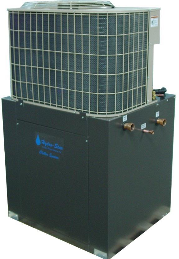
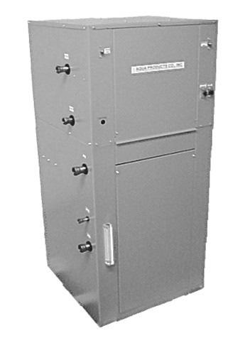
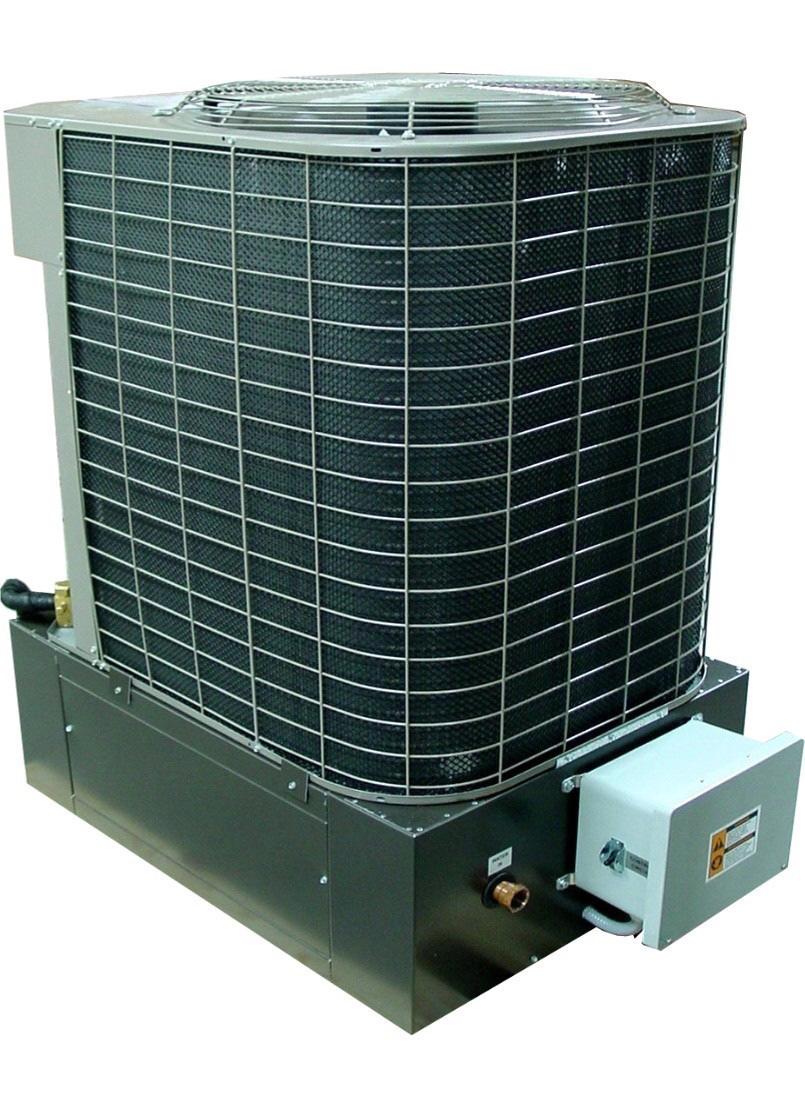
5 DCS/DCP & WCS/WCP SERIES CHILLER Aqua Products Company, Inc. has made effort to obtain the highest quality parts in the manufacturing of their Chillers. The DCS & WCS series chiller is a complete packaged chiller with a separate tank and pump which may be purchased locally or from Aqua Products Company, Inc. The DCP & WCP series chiller is a complete packaged chiller with tank and pump built into one unit. The DCS/DCP series chiller incorporates air cooled condensing units; the WCS/WCP series chiller incorporates a water cooled condensing unit. STANDARD FEATURES: 1) Evaporator The evaporator is a helical wound tube in tube type heat exchanger. The outer tube or shell which the refrigerant passes through is made of steel. The inner tube which the water passes through is made of convoluted copper for maximum heat transfer. NOTE: Other materials are available for special applications such as CUPRONICKLE, STAINLESS STEEL and DOUBLE WALL VENTED POTABLE WATER 2) High Pressure Safety The high pressure safety shuts the unit off if refrigerant pressure exceeds 425 PSI. This safety will reset automatically. 3) Low Pressure Safety The low pressure safety shuts the unit off if refrigerant is lost or low. This safety will reset automatically. 4) Control Circuit The control circuit for all chillers is 24 VAC. 5) Flow Switch The flow switch shuts off the unit in a no flow or low water flow condition. 6) Low Ambient Fan Cycle Switch The Fan Cycle Switch cycles the condensing unit fan on and off to maintain head pressure. 7) Durable Cabinet The cabinet is constructed with 16 gauge aluminum that is primed and painted. 8) All units are Factory Tested to ensure trouble free installation. Please read this installation manual completely before beginning installation of the unit. Note the procedure to follow for parts replacement and warranty claims. Reading this manual now may save you time and money later. Aqua Products Co., Inc. takes pride in its workmanship and service. Should there be any questions regarding the Chiller or this installation manual, please do not hesitate to call our Service Department at (803)
6 INSTALLATION GUIDELINES This product must be installed and serviced by a qualified, licensed technician and must conform to all local and national codes. Improper installation, adjustment, alteration, service or maintenance can cause injury or property damage. The following information is intended to assist this individual in a successful installation. LOCAL AND/OR NATIONAL CODES TAKE PRECEDENCE OVER THESE INSTALLATION INSTRUCTIONS. CAUTION: Single wall heat exchanger, not suitable for potable water applications. For potable water applications use only certified coils. Consult factory for specifications. Several conditions must be given when determining the location to install the chiller. They are as follows: 1) FOUNDATION OR FLOOR This must be strong and level for proper chiller operation. It is strongly recommended that a vibration absorption pad or like material be used since the normal vibration produced by the compressor may be amplified where the chiller cabinet meets its mountings if not insulated. 2) AIR CIRCULATION It is very important that the chiller has at least 3 feet of free space on all sides of the condensing coil and a minimum of 4 feet above the chiller where the exhaust air is discharged. No free space is required for water cooled (WCS/WCP series) chiller. 3) INDOOR VERSUS OUTDOOR INSTALLATION (FOR AIR-COOLED CHILLERS ONLY) If at all possible, air-cooled chillers should be placed outdoors. If this is not possible, it may be installed indoors if certain precautions are followed: a. Steps #1 and #2 above must be followed for air-cooled (DCS/DCP) chillers. b. The Chiller will produce large quantities of heated air in the water-cooling process. This heat must be removed from the building. In order to accomplish this, a ducted discharge should be used.!!!warning-never ATTACH ANY DUCT WORK TO THE CONDENSING UNIT!!! The fan on the condensing unit is not engineered to handle any static pressure. The ducted discharge must be constructed with its own ventilator fan to pull the heated air from the general area of the chiller. The ventilator must be sized so as not to starve the condenser of the cooling air it needs. (Consult your local distributor)
7 TABLE (2) HEADER SIZING CHART SUPPLY HEADER ALL CHILLERS RETURN HEADER ALL CHILLERS CONDENSING WATER WATER COOLED ONLY IN OUT 1.5 THRU 2.0 TON CHILLERS ¾ 1 ½ ½ 2.5 THRU 5 TON CHILLERS 1 1 ¼ ¾ ¾ 5 THRU 7.5 TON CHILLERS 1 ¼ 1 ½ TON CHILLERS 1 ½ 2 1 ¼ 1 ¼ 15 TON CHILLERS 2 ½ 3 1 ¼ 1 ¼ The header sizes in this chart are based on a maximum of 30 feet of header length and the standard pump furnished with each unit. Note: For multiple chillers, use total tonnage of units; i.e. (2) 5 ton chillers installed in parallel would equal a 10 ton load for header sizing purposing. Consult Factory, if needed. TABLE (3) MINIMUM WIRE SIZE CHART CHILLER MODEL 3 PHASE 1 PHASE WIRE SIZE DCS/DCP/WCS/WCP 2 #10 #10 DCS/DCP/WCS/WCP 3.5 #10 #10 DCS/DCP/WCS/WCP 5 #8 #10 DCS/DCP/WCS/WCP 6 #8 N/A DCS/DCP/WCS/WCP 7.5 #6 N/A DCS/DCP/WCS/WCP 10 #6 N/A ***3 phase voltage not available on DCS/DCP 2 Ton Models*** ***CHECK UNIT NAME PLATE FOR MINIMUM CIRCUIT AMPS TO DETERMINE EXACT MINIMUM WIRE SIZE***
8 PIPING SYSTEM The piping or header system is the most important installation procedure in this manual. If these recommendations are not followed, the Chiller may not operate properly. 1) Never reduce the water connections to the chiller. 2) Never reduce the pump suction. You may, however, reduce the pump discharge at the pump for DC/S 2 or DC/S 3 systems. 3) All pipe fittings and valves create restriction (head) on the system. It is very important to keep this restriction to a minimum. An easy way to do this is to use a few elbows as possible and to use 45 degree elbows. They create half the restriction of a 90 degree elbow. 4) When selecting valves, use gate valves one size larger than the pipe size. (Example: 1 pipe, 1 ¼ gate valve) The reason for this is the port or passage of most valves is one pipe size smaller than the valve. 5) Many machines have only one water inlet and one water outlet that feed two or more components on the machine. If this is the case on your machine, these lines should be removed and a separate return and supply line from the header system must be installed on each component requiring cool water. Do not use rubber hose or like materials to make these connections because they are very restrictive. Instead, use hard pipe to within one foot or less and make the final connection with an industrial grade vibration isolator-type hose. 6) It is very important that a by-pass valve be installed in the header system. (See Figures 1 & 2 for air-cooled units and Figures 1A & 2A for water-cooled units). This valve has two main purposes: a) Enables you to maintain a proper and constant back pressure on the system. b) Mixes chilled supply water with hot return water so that the chiller will not become overloaded. 7) If two or more chillers are used in one system, they must be piped in parallel, making sure to balance the flow to and from the chillers. (See Figure 1A & 2A & 3A for typical piping diagrams.)
 IT IS RECOMMENDED THAT A PRESSURE GAUGE BE INSTALLED FOR QUICK REFERENCE WHEN SETTING UP SYSTEM AND FOR NORMAL SYSTEM MONITORING.")
9 NOTE #5 PUMP CHILLER NOTE #6 VENTED STORAGE TANK THESE ARE EXAMPLES OF HEAT LOADS YOUR HEAT LOADS MAY BE DIFFERENT. NOTE #2 NOTE #3 (PRESSURE GAUGE) IT IS RECOMMENDED THAT A PRESSURE GAUGE BE INSTALLED FOR QUICK REFERENCE WHEN SETTING UP SYSTEM AND FOR NORMAL SYSTEM MONITORING. (BYPASS VALVE) USED TO ENSURE PROPER WATER FLOW THROUGH CHILLERS WHEN LOADS SHUT DOWN. WE HIGHLY RECOMMEND AN AUTOMATIC TYPE SUCH AS A PRESSURE ACTIVATED VALVE. NOTE #4 ISOLATION AND CIRCUIT SETTING VALVE. NOTE #5 PUMP ISOLATION VALVES NOTE #6 (AIR COOLED DCS SHOWN) UNITS MAY BE EITHER AIR COOLED OR WATER COOLED. FIGURE 1A NOTE #4 FAN COIL AQUA PRODUCTS CO., INC. SINGLE DCS/WCS PIPING DIAGRAM AUGUST PIPING KEY CHILLER SUPPLY SUPPLY HEADER RETURN HEADER NOTE #3 PROCESS HEAT LOAD NOTE #2
10 NOTE #6 CHILLER WATER LEVEL SIGHT GLASS FRONT NOTE #5 MAKE UP WATER THESE ARE EXAMPLES OF HEAT LOADS YOUR HEAT LOADS MAY BE DIFFERENT. NOTE #2 NOTE #3 (PRESSURE GAUGE) IT IS RECOMMENDED THAT A PRESSURE GAUGE BE INSTALLED FOR QUICK REFERENCE WHEN SETTING UP SYSTEM AND FOR NORMAL SYSTEM MONITORING. (BYPASS VALVE) USED TO ENSURE PROPER WATER FLOW THROUGH CHILLERS WHEN LOADS SHUT DOWN. WE HIGHLY RECOMMEND AN AUTOMATIC TYPE SUCH AS A PRESSURE ACTIVATED VALVE. NOTE #4 ISOLATION AND CIRCUIT SETTING VALVE. NOTE #5 CHILLER ISOLATION VALVES NOTE #6 (AIR COOLED DCP SHOWN) UNITS MAY BE EITHER AIR COOLED OR WATER COOLED. NOTE #4 FIGURE 2A FAN COIL AQUA PRODUCTS CO., INC. DCP/WCP PIPING DIAGRAM SEPT PIPING KEY SUPPLY HEADER RETURN HEADER NOTE #3 PROCESS HEAT LOAD NOTE #2
11 CHILLER #1 CHILLER #2 NOTE #7 NOTE #7 NOTE #6 NOTE #5 FIGURE 3A PUMP VENTED STORAGE TANK THESE ARE EXAMPLES OF HEAT LOADS YOUR HEAT LOADS MAY BE DIFFERENT. NOTE #2 (PRESSURE GAUGE) IT IS RECOMMENDED THAT A PRESSURE GAUGE BE INSTALLED FOR QUICK REFERENCE WHEN SETTING UP SYSTEM AND FOR NORMAL SYSTEM MONITORING. NOTE #3 (BYPASS VALVE) USED TO ENSURE PROPER WATER FLOW THROUGH CHILLERS WHEN LOADS SHUT DOWN. WE HIGHLY RECOMMEND AN AUTOMATIC TYPE SUCH AS A PRESSURE ACTIVATED VALVE. NOTE #4 ISOLATION AND CIRCUIT SETTING VALVE. NOTE #5 PUMP ISOLATION VALVES NOTE #6 ENSURE PIPING IS OF EQUAL LENGTH GOING TO EACH CHILLER WHEN PIPING MULTIPLE UNITS TOGETHER IN PARALLEL ALL UNITS MUST BE PIPED IN PARALLEL. NOTE #7 (AIR COOLED DCS SHOWN ) UNITS MAY BE EITHER AIR COOLED OR WATER COOLED. NOTE #4 AQUA PRODUCTS CO., INC. MULTIPLE DCS/WCS PIPING DIAGRAM AUGUST PIPING KEY CHILLER SUPPLY SUPPLY HEADER RETURN HEADER NOTE #3 PROCESS HEAT LOAD NOTE #2
12 TROUBLE SHOOTING FLOW CHART FOR DCS/DCP CHILLERS This flow chart assumes main power is applied, water is flowing and control circuit switch is on. Note #1 Delete phase monitor checks for single phase machines and 3 phase machines without phase monitors. Note #2: If there is no display on temperature controller the flow switch is either faulty or there is not enough flow to actuate it. Chiller won't start Note #1 Check for green light on phase monitor Red Remove power and swap main power leads L1 and L3 reapply power Green Check for green light on phase monitor END Yes Did chiller start No Red Remove power check all connections reapply power. If no green light call factory. Note #2 Check that temp. controller is set up properly and that there is an output signal on the NO terminal. Fl owchart Key Start/End Yes Did chiller start Action No Decision Reset high pressure switch Flow Direction Yes Did chiller start No Call factory
13 Correct Pump Installation For Vented Or Open Tanks Discharge Suction This installation shows the pump with a flooded suction, which means water is available at the suction port of the pump at all times. You can see by this diagram that the water is being gravity feed to the suction end of the pump from the bottom of the tank. The tank can be higher than the pump but never lower. Incorrect Pump Installation For Vented Or Open Tanks Discharge Suction This installation shows the pump without a flooded suction, which means water is not available at the suction port of the pump at all times. You can see by this diagram that the pump must try to draw the water up from the tank, but the pump is not designed to do this so damage to the pump will occur from the pump running dry. The tank can be higher than the pump but never lower.
14 ELECTRICAL Consult the front page of this manual for electrical data as it pertains to your chiller. All installations must be performed by a qualified, licensed technician and must conform to all local and national codes. 1) Use circuit breakers. The use of fuses only on a three phase system may cause single phasing and burn out the compressor. 2) All field applied wiring must comply with local and national codes, but must be at least the sizes indicated in Table 3. 3) All field connections to the chiller must be made to L1, L2, and L3 main terminals of the compressor contactor. 4) There is a machine ground lug provided. These must be hooked up to avoid personal shock or injury. 5) All control circuit wiring is 24 VAC. 6) For units with a crankcase heater, ensure power is left on to the unit at all times after the installation is complete.!!!if STEP 6 IS NOT FOLLOWED, THERE WILL BE COMPRESSOR DAMAGE!!! Controls, Safety Devices and Their Features 1) High Pressure Safety- The high-pressure safety will shut the unit off if pressure exceeds 425 psi. This will automatically reset. If the safety trips, it should be checked by a qualified technician. 2) Low Pressure Safety- The low-pressure safety protects the compressor from overheating if the refrigerant charge is lost or less than 10 PSI. This will automatically reset. This device opens at 10 PSI and automatically resets at 25 PSI. If the unit appears to be short-cycling, it should be checked by a qualified technician. 3) Low Ambient Fan Cycle Switch- The Fan Cycle Switch cycles the condensing unit fan on and off to maintain the systems head pressure for proper operation below 60 degrees F. 4) Flow Switch- The flow switch shuts the unit off in a no flow or low water flow condition to prevent the evaporator from freezing.
15 WATER TREATMENT!!!DO NOT USE ANTI-FREEZE IN GALVANIZED PIPE SYSTEMS!!! Precautions against system freezing and fouling must be taken to ensure trouble free operation. To accomplish this we suggest several brands of anti-freeze. Not only does glycol protect against freeze up, but it also incorporates an additive package, which contains corrosion, suspension, and anti-foaming agents. The brands we recommend are Dow frost, a propylene glycol based anti-freeze, pipe saver, and NuCalgon. Note: NuCalgon has additives recommended for our systems. If the Chiller is to be installed on an already existing system, it is recommended that the system be cleaned out with a trisodium phosphate (TSP) solution prior to installing the anti-freeze and to flush the system thoroughly with fresh water. Never use less than 30% of glycol mixture since you need at least this amount in order for the corrosion inhibitors to do their job. Nor should you use more than 60% since glycol's become aggressive above this concentration. Remember, this is a one-time investment for years so please make every effort possible to properly install the glycol the first time so you won t be disappointed in the future. FREEZE PROTECTION CHART % Anti-freeze Freezing temperature % water by volume (Degrees f) by volume Do not use glycol concentrations greater than 60% or less than 30%. For more information on DOW Brand anti-freeze call: Nu Calgon call: For more information on Pipe Saver anti-freeze call: Virginia KMP Corporation call: ***NOTE: AUTOMOBILE ANTI-FREEZE WILL CAUSE SERIOUS DAMAGE TO YOUR CHILLER AND VOID YOUR WARRANTY!!!***
 warrants this product to be free from defects in factory workmanship and material under normal use and service and will, at it s option repair or replace parts proved to have such defects for")
16 APCI Limited Warranty Aqua Products Company, Inc. (APCI) warrants this product to be free from defects in factory workmanship and material under normal use and service and will, at it s option repair or replace parts proved to have such defects for a period of (1) year. Time period is measured from the date of installation or, if such date is not determinable, from the date of shipment of the product from the APCI factory. For your benefit and protection, return the warranty registration card to APCI promptly after installation. This will initiate the warranty period and allow us to contact you, should it become necessary. In the absence of a recorded Warranty Registration Card, the warranty period will begin upon product shipment form APCI. This Warranty extends only to the original consumer purchaser and is non-transferable. For this warranty to apply, the product must be installed according to APCI recommendations and specifications, and in accordance with local, state and national codes, and product must not be removed from it s place of original installation. The warranty period for repair or replacement parts provided hereunder shall not extend beyond the warranty period stated above. This warranty applies only to products installed in the United States and Canada. EXCLUSIONS 1. Shipping, labor, glycol, refrigerant, truck time or material charges. 2. Damages resulting from transportation, installation, or servicing. 3. Damages resulting from accident, abuse, fire, flood, alteration, or acts of god. Tampering, altering, defacing or removing the product serial number tag will serve to void this warranty. 4. Damages resulting from use of the product in a corrosive atmosphere. 5. Damages resulting from inadequacy or interruption of electrical service, improper voltage conditions, blown fuses, or other like damages. 6. Damages resulting from freezing. 7. Damages resulting from operation with inadequate supply of air or water. 8. Damages resulting from use of components or accessories not approved by APCI. This warranty is in lieu of all other warranties, express or implied, including the implied warranties of merchantability and fitness for a particular purpose. Some states do not allow the disclaimer of implied warranty, so that the above disclaimer may not apply to you. Some states allow only partial limitation on implied warranties to limit the duration of implied warranties to the duration of the express warranty. In such states, the duration of implied warranties is hereby expressly limited to the duration of the express warranty on the face hereof. In no event, whether as a result of breach of warranty or contract, tort (including negligence) strict liability or otherwise, shall APCI be liable for special, incidental, or consequential damages, including but not limited to loss of use of the equipment or associated equipment, lost revenues or profits, cost of substitute equipment or cost of fuel or electricity. The above limitations shall inure to the benefit of APCI supplies and subcontractors. The above limitation on consequential damages shall not apply to injuries to persons in the case of consumer goods. Some states do not allow the exclusion or limitation of liability for consequential or incidental damages, or for strict liability tort, so that the above exclusions and limitations may not apply to you. APCI does not assume, or authorize any other person to assume for APCI and other liability for the sale of this product. This warranty gives you specific legal rights you may also have other rights which vary form state to state. TO OBTAIN WARRANTY SERVICE Notify your installing or servicing dealer, preferable in writing, of the problem as soon as possible after its discovery. Be sure to include product model number, serial number, installation date and the nature of the problem. If a response is not received within a reasonable time notify APCI at P.O. Box 39 Prosperity, SC USA. Service requests sent to APCI without prior dealer contact will be referred back to dealer. For Owners Information Product Model No. Installation Date Unit Serial No. Installing Dealer
OWNER S MANUAL READ AND SAVE THESE INSTRUCTIONS MODELS 4000, 5000, 6000 & 7000 HUMIDIFIERS. Includes Safety, Operating and Maintenance Instructions
 READ AND SAVE THESE INSTRUCTIONS OWNER S MANUAL MODELS 000, 000, 000 & 000 HUMIDIFIERS 011 Unitary Products Group 00 York Drive, Norman, OK 09 Includes Safety, Operating and Maintenance Instructions 100091.11
PDF Created with deskpdf PDF Writer - Trial ::
 Instruction Manual Index Introduction Uncrating and Checking for Damage Locating Your Unit Installation Fill Tank Process Connections Pre Startup Startup Sequence Trouble Shooting Chart Operating Lights
Fan Speed. Auto Swing. Timer. Power. Mode. Fan. Only. Saver. Temp. Dry. Fan. Speed. Auto Swing. Timer. Power. Mode. Saver. Only. Temp.
 Mode 0F Cool Dry Temp Fan Speed Timer 0n/0ff Money Saver Mode 0F hr Fan Cool Only Dry Temp Auto Swing Power Fan Speed hr Timer 0n/0ff Money Saver Fan Only Auto Swing Power For inner cleaning, contact
INSTALLATION INSTRUCTIONS
 INSTALLATION INSTRUCTIONS FOR AQUECOIL HYDRONIC HEATING UNITS GENERAL INFORMATION The AQUECOIL Hydronic Heating Unit is offered in many different capacities and physical configurations in order to match
USER S INFORMATION MANUAL
 USER S INFORMATION MANUAL AIR HANDLERS MODELS: ALL ISO 9001 Certified Quality Management System TABLE OF CONTENTS CONTACT INFORMATION............................... 1 HOW YOUR AIR HANDLER WORKS........................
REFRIGERATED DROP-INS (2-6)FT-DI Installation and Operating Manual
FT-DI Installation and Operating Manual") REFRIGERATED DROP-INS (2-6)FT-DI Installation and Operating Manual For service information call 800-544-3057 Please have the following information available before calling. Information can be found on
REFRIGERATED DROP-INS (2-6)FT-DI Installation and Operating Manual For service information call 800-544-3057 Please have the following information available before calling. Information can be found on
USER S INFORMATION MANUAL
 USER S INFORMATION MANUAL MODELS: All Residential Multi-position Gas Furnaces (33 Models) EFFICIENCY RATING CERTIFIED ISO 9001 Certified Quality Management System CONTACT INFORMATION...............................
INSTALLATION AND MAINTENANCE INSTRUCTIONS FOR ROOFTOP UNITS
 INSTALLATION AND MAINTENANCE INSTRUCTIONS FOR ROOFTOP UNITS SIZES FROM 600 CFM TO 9,000 CFM I/O MANUAL Horizontal/Modular/Vertical/Rooftop AHU 2011pg. 1 INTRODUCTION READ THE ENTIRE INSTALLATION, OPERATION
INSTRUCTIONS! DO NOT DISCARD!
 INSTRUCTIONS! DO NOT DISCARD! CAUTION! Do NOT install where injury might occur due to Moving parts, Sharp corners, Hot surfaces or electrical components d N0417 Page 1 of 10 INSTALLATION INSTRUCTIONS CAUTION
5+2 DAY. Digital Thermostat. residential. & 1-cool. up to 2-heat PROGRAMMABLE THERMOSTAT. Venstar Inc. 05/08
 Digital Thermostat residential THERMOSTAT 5+2 DAY PROGRAMMABLE up to 2-heat & 1-cool HEAT PUMP Stages: 2-Heat, 1-Cool Battery or System Powered Auxiliary Heat Indicator Back-Lit Digital Display Fahrenheit
Installation & Operation Manual Ice Cream Freezers
 Installation & Operation Manual Ice Cream Freezers Please read this manual completely before installing or operating this unit! BACF11 BACF15 Blue Air reserves the right to make product modification at
INSTALLATION AND OPERATING MANUAL
 INSTALLATION AND OPERATING MANUAL Refrigerated Island Merchandiser FOR PARTS & SERVICE Contact: Piper Products, Inc. Phone: (800) 544-3057 Ask for Service Department IMPORTANT! This manual contains important
MANUAL 8/12/05. Model BKP TM 100 INSTALLATION, OPERATION & MAINTENANCE. Commercial High Efficiency Heat Pipe Dehumidifier
 MANUAL 8/12/05 INSTALLATION, OPERATION & MAINTENANCE Commercial High Efficiency Heat Pipe Dehumidifier Model BKP TM 100 Heat Pipe Technology, Inc. 6904 Parke East Blvd. Tampa FL 33610 Tel: (813) 470-4250
OWNER'S MANUAL T0140. Contents Page #
 Digital Thermostat residential THERMOSTAT T0140 NON- PROGRAMMABLE up to 2-heat & 1-cool PUMP Stages: 2-Heat, 1-Cool Battery or System Powered Auxiliary Heat Indicator Fahrenheit or Celsius Bi-Color LED
AIC Brazed Plate Heat Exchanger Operating and Instruction Manual
 AIC Brazed Plate Heat Exchanger Operating and Instruction Manual Advanced Industrial Components Page 1 of 8 Customer Service Call: 1-888-738-1350 1.0 Installation 1.1 Mounting/support unit: a) On a shelf
User Manual. Wine Cellar
 User Manual Wine Cellar MODEL: WWT060MB WWT080MB WWT100MB WWT120MB 1. READ these instructions carefully before installing and operating the Wine Cellar. Keep them for further reference. 2. Record in the
INSTALLATION AND OPERATING MANUAL
 INSTALLATION AND OPERATING MANUAL Refrigerated Merchandisers with Air-Over Displays Refrigerated Low-Profile Mobile Merchandiser Refrigerated High-Profile Mobile Merchandiser Refrigerated Grab-N-Go Merchandiser
APPLICATION MANUAL FOR SCU SERIES COMPRESSOR UNITS AND SWU SERIES WATER COOLED CONDENSING UNITS
 APPLICATION MANUAL FOR SCU SERIES COMPRESSOR UNITS AND SWU SERIES WATER COOLED CONDENSING UNITS SCU-30 SWU-30 Napps Technology Corporation P.O. Box 3066 Longview, TX 75606-3066 Phone: (903) 758-2900 FAX:
INSTALLATION AND OPERATING MANUAL
 INSTALLATION AND OPERATING MANUAL Refrigerated Cases with Air-Over Displays Refrigerated High Profile Grab-N-Go FOR PARTS & SERVICE Contact: Piper Products, Inc. Phone: (800) 544-3057 Ask for Service Department
Blue Air. Commercial Refrigeration Inc. Installation & Operation Manual Ice Cream Freezers
 Blue Air Commercial Refrigeration Inc. Installation & Operation Manual Ice Cream Freezers Please read this manual completely before installing or operating this unit! BACF11 BACF15 BACRF14 Blue Air reserves
Installation Instructions PP-AS20 Anti-Scale System
 Installation Instructions PP-AS20 Anti-Scale System THIS UNIT MUST BE INSTALLED BY A LICENSED PLUMBER TO VALIDATE THE WARRANTY. COMPONENTS PP-AS20 Filter Housing PP-AS20R Filter Cartridge Installation
INTRODUCTION. Special Applications of Package Air Conditioners. Instant Cooling Requirement in Wedding Ceremonies
 Pakistan s Largest Manufacturers of Air-Conditioners PACKAGE TYPE UNIT FOR MOBILE APPLICATIONS Provides Turnkey Projects Conceptual Planning to Commissioning of HVACR Projects THE LARGEST MANUFACTURER
EBAC MODEL CD60 INDUSTRIAL DEHUMIDIFIER OWNER S MANUAL
 EBAC MODEL CD60 INDUSTRIAL DEHUMIDIFIER OWNER S MANUAL CD60 OWNERS MANUAL Page 1 of 9 INTRODUCTION Designed for a wide range of applications, the CD60 dehumidifier is a rugged, industrial unit which utilizes
INSTRUCTIONS! DO NOT DISCARD!
 INSTRUCTIONS! DO NOT DISCARD! CAUTION! Do NOT install where injury might occur due to Moving parts, Sharp corners, Hot surfaces or electrical components dcn0620 Page 1 of 12 INSTALLATION INSTRUCTIONS CAUTION
Owner s Manual Use with most Heat Pump systems: 1-Heat, 1-Cool 2-Heat, 1-Cool
 Owner s Manual Model S1-THEH21NS HVAC SERVICE PARTS TM Heat Pump Non- Programmable Digital T h e rm ostats t a t Use with most Heat Pump systems: 1-Heat, 1-Cool 2-Heat, 1-Cool Control up to 2-Heat & 1-Cool
SPA BLOWER OWNER'S MANUAL XXXX, XXXX, XXXX, XXXX, XXXX, XXXX fax
 SPA BLOWER OWNER'S MANUAL 80015-XXXX, 80016-XXXX, 80017-XXXX, 80018-XXXX, 80019-XXXX, 80020-XXXX fax 888.610.3839 2015 323300-015 6/15 THIS PAGE INTENTIONALLY LEFT BLANK. 2 Operating Instructions and Parts
INSTALLATION AND OPERATING MANUAL
 INSTALLATION AND OPERATING MANUAL Salad Bars Olive Bars Food Prep Cases Refrigerated Cases with Air-Over Displays Refrigerated Cases with Coppered Cold Well Displays Cases with Under-Counter Refrigerators
Owner s Manual Refrigerated Compressed Air Dryers Models F-200, 250, 300 & F350
 Owner s Manual Refrigerated Compressed Air Dryers Models F-200, 250, 300 & F350 Read carefully before attempting to assemble, install, operate or maintain the product described. Protect yourself and others
Installation Instructions
 EZXCAB Sizes 016 and 020 High Efficiency Air Filtration System Installation Instructions JAN High Efficiency Air Filtration System Fig. 1 - EZXCAB C04001 NOTE: Read the entire instruction manual before
Non-Programmable Digital Thermostat
 OWNER'S MANUAL MODEL P474-0140 Non-Programmable Digital Thermostat HEAT PUMP THERMOSTAT 2 HEAT, 1 COOL emergency aux. heat normal energy save Fan On Fan Auto Millivolt Compatible Battery or System Powered
EBAC MODEL KOMPACT INDUSTRIAL DEHUMIDIFIER OWNER S MANUAL
 EBAC MODEL KOMPACT INDUSTRIAL DEHUMIDIFIER OWNER S MANUAL KOMPACT OWNERS MANUAL Page 1 of 9 INTRODUCTION Designed for a wide range of applications, the Kompact is a rugged, industrial unit, which utilizes
INSTRUCTIONS! DO NOT DISCARD!
 INSTRUCTIONS! DO NOT DISCARD! CAUTION! Do NOT install where injury might occur due to Moving parts, Sharp corners, Hot surfaces or electrical components dn0521 Page 1 of 12 INSTALLATION INSTRUCTIONS CAUTION
SAFETY ALERT SYMBOLS SAFETY PRECAUTIONS
 SAFETY ALERT SYMBOLS Read and follow all safety information carefully. The signal words used in this manual are selected as shown below and based on an assessment of the degree of potential injury or damage
EBAC MODEL BD-150 ( ) INDUSTRIAL DEHUMIDIFIER OWNER S MANUAL
 INDUSTRIAL DEHUMIDIFIER OWNER S MANUAL") EBAC MODEL BD-150 (1025000) INDUSTRIAL DEHUMIDIFIER OWNER S MANUAL BD-150 OWNERS MANUAL Page 1 of 12 INTRODUCTION Designed for a wide range of applications, the BD-150 dehumidifier is a super high capacity
EBAC MODEL BD-150 (1025000) INDUSTRIAL DEHUMIDIFIER OWNER S MANUAL BD-150 OWNERS MANUAL Page 1 of 12 INTRODUCTION Designed for a wide range of applications, the BD-150 dehumidifier is a super high capacity
WKS 4000 SERIES (USA only) --INSTALLATION INSTRUCTIONS--
 --INSTALLATION INSTRUCTIONS--") 8610 Production Avenue San Diego, California 92121 (858) 566-7465 Fax (858) 566-1943 WKS 4000 SERIES (USA only) --INSTALLATION INSTRUCTIONS-- Thank you for choosing a BREEZAIRE cooling unit. We believe
8610 Production Avenue San Diego, California 92121 (858) 566-7465 Fax (858) 566-1943 WKS 4000 SERIES (USA only) --INSTALLATION INSTRUCTIONS-- Thank you for choosing a BREEZAIRE cooling unit. We believe
EBAC MODEL NEPTUNE INDUSTRIAL DEHUMIDIFIER OWNER S MANUAL
 EBAC MODEL NEPTUNE INDUSTRIAL DEHUMIDIFIER OWNER S MANUAL NEPTUNE OWNERS MANUAL Page 1 of 9 INTRODUCTION Designed for a wide range of applications, the Neptune dehumidifier is a super high capacity industrial
AQUA LOGIC S MULTI-TEMP Water-Cooled Marine Duty Series chiller
 AQUA LOGIC S MULTI-TEMP Water-Cooled Marine Duty Series chiller INSTALLATION & OPERATING INSTRUCTIONS Effective 8-19-15 Thank you for purchasing an Aqua logic chiller. It has been designed and built to
WMWLB / WMWFM / WTWLB / WTWFM Series Hydronic Heating Unit
 January 2008 WMWLB / WMWFM / WTWLB / WTWFM Series Hydronic Heating Unit Installation Operation Maintenance The units are designed for permanent up flow, counter flow, or horizontal left or right airflow
Air Cleaning Equipment, Inc. 303 N. Main St. Broadway, NC iers.com
 Read and Save These Instructions Horizon Galaxy - Installation and Operations Manual Air Cleaning Equipment, Inc. 303 N. Main St. Broadway, NC 27505 www.horizondehumidif iers.com 1 Safety Notes: The Horizon
Outdoor Refrigerator USER S MANUAL
 Outdoor Refrigerator USER S MANUAL MODEL Number:BLZ-SSRF-40DH IMPORTANT:READ THIS USER S MANUAL PRIOR TO CONNECTING POWER AND USE Before the refrigerator is used, it must be PROPERLY POSITIONED, LEVELED
Spa Control System OWNER S MANUAL
 LIMITED WARRANTY ONE YEAR LIMITED WARRANTY: UNITED SPAS, INC. warrants, to the original purchaser, the Spa Equipment against defects in materials or workmanship for a period of one year from date of purchase.
IMPORTANT INFORMATION - PLEASE READ CAREFULLY
 Honeywell Garrett Direct Fit Performance Intercooler 2015+ 3.5L / 2.7L Ford F150 EcoBoost Bill of Materials and Precautions Application: 2015+ Ford F150 3.5L / 2.7L Eco Boost Part Number: 870702-6001 Part
5+2 DAY. OWNER S MANUAL Venstar Inc. 05/08
 Digital Thermostat residential THERMOSTAT 5+2 DAY PROGRAMMABLE up to 1-heat & 1-cool PUMP Stages: 1-Heat, 1-Cool Battery or System Powered Back-Lit Digital Display Fahrenheit or Celsius Service Filter
INSTRUCTION MANUAL HS-229G
 INSTRUCTION MANUAL HS-229G 510977 STEP 1 - Where to Install the Thermostatic Steam Trap Determine where to install the thermostatic steam trap based on the following information. a. The trap should be
MaxLite LED MICRO-T PANEL
 ` Installation Instructions General Safety Information To reduce the risk of death, personal injury or property damage from fire, electric shock, falling parts, cuts/abrasions, and other hazards read all
SLIDER CASEMENT AIR CONDITIONER
 OWNER S GUIDE READ AND SAVE THESE INSTRUCTIONS SLIDER CASEMENT AIR CONDITIONER ROTARY CONTROL P/N 309000854 (11/03) ROOM AIR CONDITIONER WARRANTY Your product is protected by this warranty Your appliance
Model RGAC/SGAC Self Contained Cooling/Gas Heat MODELS RGAC & SGAC - R22 USER'S INFORMATION, MAINTENANCE AND SERVICE MANUAL
 Model RGAC/SGAC Self Contained Cooling/Gas Heat Supersedes: 145.24-O1 (708) Units Form 145.24-O1 (908) MODELS RGAC & SGAC - R22 USER'S INFORMATION, MAINTENANCE AND SERVICE MANUAL CATEGORY III GAS HEATING/ELECTRIC
Horizontal Bottle Cooler Installation and Operation Manual
 Speeds Up the Pace of Innovation Horizontal Bottle Cooler Installation and Operation Manual Please read this manual completely before attempting to install or operate this equipment! TBC-50SD, 50SB/ TBC-95SD,
(HSTAT Series) Instruction Manual
 Instruction Manual") Silicone Rubber Heating Tapes with Adjustable Thermostat Control (HSTAT Series) Instruction Manual Read and understand this material before operating or servicing these heating tapes. Failure to understand
Silicone Rubber Heating Tapes with Adjustable Thermostat Control (HSTAT Series) Instruction Manual Read and understand this material before operating or servicing these heating tapes. Failure to understand
SAFETY ALERT SYMBOLS SAFETY PRECAUTIONS
 SAFETY ALERT SYMBOLS Read and follow all safety information carefully. The signal words used in this manual are selected as shown below and based on an assessment of the degree of potential injury or damage
Owner s Manual Refrigerated Compressed Air Dryer Model F-50
 Owner s Manual Refrigerated Compressed Air Dryer Model F-50 Read carefully before attempting to assemble, install, operate or maintain the product described. Protect yourself and others by observing all
OPERATION & INSTALLATION MANUAL
 OPERATION & INSTALLATION MANUAL Model: SIO 14 & SIO 18 Electric Tankless Hot Water Generators Table of Contents SAFETY INFORMATION... 1 INTRODUCTION... 2 Unit Operation:... 2 Unit Freezing:... 3 Maintenance:...
Ion Genesis II Pump Controller Digital Level Control with Pump Alternation and High Water Alarm
 Page 1 of 8 General Overview Thank you for purchasing an Ion Genesis controller. Take the time to read the instructions carefully before using this appliance. We strongly recommend that you keep this instruction
Installation and Service Manual. In-Floor Warming Module external desuperheater for 3rd party air source heat pumps
 Installation and Service Manual IFM-Series In-Floor Warming Module Model Size 48 In-Floor Warming Module external desuperheater for 3rd party air source heat pumps Maritime Geothermal Ltd. P.O. Box 2555
Industrial Dehumidifier Operating Instructions. Model: VG 1500
 Industrial Dehumidifier Operating Instructions Model: VG 1500 Read and save these instructions. This instruction manual provides important information concerning the use and care of the B-Air Vantage 1500
Carbon Monoxide (CO) Detecting Ventilation Fan Controller Model 120VC Single Relay (100/25 PPM) (200/35 PPM)
 Detecting Ventilation Fan Controller Model 120VC Single Relay (100/25 PPM) (200/35 PPM)") Carbon Monoxide (CO) Detecting Ventilation Fan Controller Model 120VC Single Relay 905-0005-01 (100/25 PPM) 905-0005-02 (200/35 PPM) 1. INTRODUCTION Your COSTAR VC carbon monoxide detecting ventilation
Carbon Monoxide (CO) Detecting Ventilation Fan Controller Model 120VC Single Relay 905-0005-01 (100/25 PPM) 905-0005-02 (200/35 PPM) 1. INTRODUCTION Your COSTAR VC carbon monoxide detecting ventilation
26 LB CAPACITY ICE MAKER
 26 LB CAPACITY ICE MAKER INSTRUCTION MANUAL CATALOG NUMBER BIMY126S Thank you for choosing BLACK+DECKER! PLEASE READ BEFORE RETURNING THIS PRODUCT FOR ANY REASON. If you have a question or experience a
EBAC MODEL CD30 INDUSTRIAL DEHUMIDIFIER OWNER S MANUAL
 EBAC MODEL CD30 INDUSTRIAL DEHUMIDIFIER OWNER S MANUAL Ebac Industrial Products, Inc. 700 Thimble Shoals Blvd, Suite 109 Newport News, VA. 23606-2575 Tel: (757) 873 6800 Fax: (757) 873 3632 Website www.ebacusa.com
User s Manual and Warranty Information for Counterweighted Chain Drive ThyssenKrupp Access
 II User s Manual and Warranty Information for Counterweighted Chain Drive ThyssenKrupp Access Part #2139703 Rev. G II Table of Contents Introduction...3 Elevator Overview...4 Description of Features...5-7
OPERATION MANUAL Dated: 04/09/2018 Document Name: SHV _OM Page 1 of 8. Ion Technologies SHV40, 75 & 100 Sewage Ejector Pump SAFETY WARNINGS
 Ion Technologies SHV40, 75 & 100 Sewage Ejector Pump Page 1 of 8 biohazard risk exists. Installer(s) and/or service personnel must use proper Personal Protective Equipment and follow handling procedures
SEISCO SUPERCHARGER EXTENDER/BOOSTER INSTALLATION GUIDE & OWNERS MANUAL
 SEISCO SUPERCHARGER EXTENDER/BOOSTER INSTALLATION GUIDE & OWNERS MANUAL This manual is provided as a guide to installation. All installations must comply with any and all local and national electrical
14+ SEER R-410a AIR CONDITIONERS. Aluminum Coil Series. Efficiencies up to 14+ SEER/12 EER. Nominal Sizes Ton. Capacities 16.
 14+ SEER R-410a Coil Company, L.P AIR CONDITIONERS UNITED STATES PATENT #D557,394S #D557,395S R-410A Aluminum Coil Series Efficiencies up to 14+ SEER/12 EER Nominal Sizes 1.5-5 Ton Capacities 16.6 to 56
Warranty. Thanks. Thank you for purchasing the Oliso Smart Iron, a safer, smarter way to iron.
 User Manual Warranty Oliso, Inc. warrants that for a period of one year from the date of the original purchase, this product will be free from defects in material and workmanship, when utilized for normal
FOR EASY, FAST INSTALLATION AND FOR RESULTS
 Page 1 INSTALLATION & OPERATING INSTRUCTIONS FOR FEDERAL FLOOR FURNACE OFB-100 AND OFB100L UNPACK SHIPMENT CAREFULLY AND INSPECT FOR DAMAGE. ALL GOODS ARE CAREFULLY MANUFACTURED, INSPECTED, CHECKED, AND
Thermostat Remote Control & Receiver
 OWNER S MANUAL P/N 33CSIRRCVR-01 Thermostat Remote Control & Receiver Allows remote control operation of basic thermostat functions Unique Warmer & Cooler commands Compatible with thermostat models: 33CS450-01,
Silicone Rubber Heating Tape with Adjustable Thermostat Control (HSTAT Series) Instruction Manual
 Instruction Manual") Silicone Rubber Heating Tape with Adjustable Thermostat Control (HSTAT Series) Instruction Manual Read and understand this material before operating or servicing these heating tapes. Failure to understand
Silicone Rubber Heating Tape with Adjustable Thermostat Control (HSTAT Series) Instruction Manual Read and understand this material before operating or servicing these heating tapes. Failure to understand
IAQ Series. Bosch IAQ Photo Catalytic Oxidizer (PCO) Residential Application. Installation Manual and Owner s Guide
 Residential Application. Installation Manual and Owner s Guide") Installation Manual and Owner s Guide IAQ Series Bosch IAQ Photo Catalytic Oxidizer (PCO) Residential Application PCOB-09012-0--A - 9" PCO BULB PCOB-14024-0--A - 14" PCO BULB 67202220344 Revised 07-12
Installation Manual and Owner s Guide IAQ Series Bosch IAQ Photo Catalytic Oxidizer (PCO) Residential Application PCOB-09012-0--A - 9" PCO BULB PCOB-14024-0--A - 14" PCO BULB 67202220344 Revised 07-12
55-Gallon Dispenser Package
 INSTRUCTIONS-PARTS LIST INSTRUCTIONS This manual contains important warnings and information. READ AND KEEP FOR REFERENCE. 308 666 Rev. A Husky 715 55-Gallon Dispenser Package 100 psi (6.9 bar) Maximum
Owner s Manual Refrigerated Compressed Air Dryers Models F-3528, F-3529, F-3530, F-3531 & F-3532
 Owner s Manual Refrigerated Compressed Air Dryers Models F-3528, F-3529, F-3530, F-3531 & F-3532 Read carefully before attempting to assemble, install, operate or maintain the product described. Protect
Owner s Manual Refrigerated Compressed Air Dryers Model F-100
 Owner s Manual Refrigerated Compressed Air Dryers Model F-100 Read carefully before attempting to assemble, install, operate or maintain the product described. Protect yourself and others by observing
DUAL VOLTAGE REFRIGERATORS 220/240 VOLTS AC AND 12/24 VOLTS DC INSTALLATION AND OWNER S MANUAL
 DUAL VOLTAGE REFRIGERATORS 220/240 VOLTS AC AND 12/24 VOLTS DC INSTALLATION AND OWNER S MANUAL Service Information If service or parts are required, contact the nearest Norcold Service Center. To find
CHILLER. Operator s & Installation Manual
 CHILLER MODELS: CH1001-A Operator s & Installation Manual Release Date: August 9, 2002 Publication Number: 620914301 Revision Date: May 6, 2010 Revision: E Visit the IMI Cornelius web site at www.cornelius.com
DRY-PAK INDUSTRIAL AIR DRYER Installation and Instruction Manual
 DRRRRDRY-PAK Instruction and Installation Manual IB-160 Rev. B P/N 36595 Registered by UL to ISO 9001 DRY-PAK INDUSTRIAL AIR DRYER Installation and Instruction Manual INSTALLATION: Models DS0-00-000 through
Surna 25-Ton Chiller Operating & Maintenance Manual
 www.surna.com 303.993.5271 Surna 25-Ton Chiller Operating & Maintenance Manual Models: 300F3-3. 300F4-3, 300FW-3 Revised: July 2015 Table of Contents Warranty Information 4 Limited Warranty 4 Limitation
Installation & Maintenance Instructions
 PRH Series Plenum Heaters Installation & Maintenance Instructions Dear Owner, Congratulations! Thank you for purchasing this new heater manufactured by Marley Engineered Products. You have made a wise
USER S INFORMATION MANUAL
 USER S INFORMATION MANUAL MODELS: All Residential Multi-position Gas Furnaces (33 Models) TABLE OF CONTENTS CONTACT INFORMATION............................... 1 SAFETY................................................
Turbo Air Speed up the Pace of Innovation TBB-4SB CAUTION! PLEASE KEEP POWER SWITCH ON BEFORE OPERATING THIS EQUIPMENT
 Turbo Air Speed up the Pace of Innovation CAUTION! PLEASE KEEP POWER SWITCH ON BEFORE OPERATING THIS EQUIPMENT Underbar Equipment Back Bars Installation and Operation Manual Please read this manual completely
AIR CONDITIONER ELECTRONIC CONTROL
 READ AND SAVE THESE INSTRUCTIONS AIR CONDITIONER ELECTRONIC CONTROL ROOM AIR CONDITIONER WARRANTY Your product is protected by this warranty Your appliance is warranted by Electrolux. Electrolux has authorized
INSTALLATION & OPERATING INSTRUCTIONS FOR CEILING MOUNT AIR HANDLERS AC SERIES
 C US INSTALLATION & OPERATING INSTRUCTIONS FOR CEILING MOUNT AIR HANDLERS AC SERIES Made in the USA by: Goodman Manufacturing Company, L.P. I0-240B 2550 North Loop West, Suite 400, Houston, TX 77092 www.goodmanmfg.com
Henny Penny Island Warmer Model HMI-103 Model HMI-105 TECHNICAL MANUAL
 Henny Penny Island Warmer Model HMI-103 Model HMI-105 TECHNICAL MANUAL THIS PAGE INTENTIONALLY LEFT BLANK. Section TABLE OF CONTENTS Page Section 1. TROUBLESHOOTING... 1-1 1-1. Introduction... 1-1 1-2.
Rev. A AUGUST 2012 RNP SERIES REFRIGERATED COMPRESSED AIR DRYERS OPERATOR MANUAL RNP25 RNP35 RNP50
 3227447 Rev. A AUGUST 2012 RNP SERIES REFRIGERATED COMPRESSED AIR DRYERS OPERATOR MANUAL RNP25 RNP35 RNP50 GENERAL SAFETY INFORMATION 1. PRESSURIZED DEVICES: This equipment is a pressure containing device.
M1200 Series Limited Warranty Dependability Promise
 M1200 Series Limited Warranty Dependability Promise Warranty effective for equipment manufactured after January 1, 2011 Dear Customer, Congratulations on your decision to purchase the most reliable heating
Installation, Operation, and Maintenance Manual
 Installation, Operation, and Maintenance Manual Product Preservers Anti-Scale System Chemical-Free, Salt-Free Scale Prevention Introduction The Product Preservers Anti-Scale System will condition the tap
Installation Instructions
 Model Air Conditioning & Heating Heat Pump 5+2 Day Programmable Digital Thermostat Control up to 2-Heat & 1-Cool Battery or System Powered Auxiliary Heat Indicator Fahrenheit or Celsius Service Filter
55-Gallon Dispenser Package
 INSTRUCTIONS-PARTS LIST Husky 515 55-Gallon Dispenser Package 08666 Rev.C INSTRUCTIONS This manual contains important warnings and information. READ AND KEEP FOR REFERENCE. 100 psi(6.9 bar) Maximum Air
Ion Endeavor Pump Controller Digital Level Control with Pump Alternation and High Water Alarm
 Ion Endeavor Controller Digital Level Control with Alternation Page 1 of 8 General Overview The Ion Endeavor is a pump controller that senses a water level of up to 72", has a configurable water level/pump
Installation and Testing of Inverted Bucket Steam Traps Manual
 Installation and Testing of Inverted Bucket Steam Traps Manual 307-EN Please read and save these instructions Armstrong IB Traps Installation Before Installing Run pipe to trap. Before installing the trap,
EarthLinked SW Series Compressor Unit R-410A Quik-Start Instructions
 EarthLinked SW Series Compressor Unit R-410A Quik-Start Instructions CONTENTS PAGE Pre-Installation 3 Placement & Mechanical Information 4 System Application Options 10 Antifreeze Protection 14 Electrical
Henny Penny Blast Chiller/Freezer Models BCC/BCR-140 Models BCC/BCR-175 Models BFR/BCR-350
 Henny Penny Blast Chiller/Freezer Models BCC/BCR-140 Models BCC/BCR-175 Models BFR/BCR-350 TECHNICAL MANUAL Section TABLE OF CONTENTS Page Section 1. TROUBLESHOOTING... 1-1 1-1. Introduction... 1-1 1-2.
MACH N-407 Heat Pump Air-Cooled Chiller
 MACH060-01-N-407 Heat Pump Air-Cooled Chiller Heat Pump Air-Cooled Chillers for Global Residential and Light Commercial Microclimates MACH NOMENCLATURE BREAKDOWN MACH-060-01 - N - 407 Refrigerant Type
WatchDog NXT60. Installation and Operations Manual. Seaira Global, LLC NC Highway 50 Surf City, NC (910)
") WatchDog NXT60 Installation and Operations Manual Seaira Global, LLC 14021 NC Highway 50 Surf City, NC 28445 (910) 660-0962 Table of Contents Important Notes 2 Warranty Registration 2 Specifications 3
WatchDog NXT60 Installation and Operations Manual Seaira Global, LLC 14021 NC Highway 50 Surf City, NC 28445 (910) 660-0962 Table of Contents Important Notes 2 Warranty Registration 2 Specifications 3
InstructIon Manual KrEs EQuIPMEnt stands
 Instruction Manual Instruction Manual SELF-CONTAINED AND REMOTE Kairak KRES model refrigerated equipment stand units are available in many lengths from 36 to 120 inches long. These units are available
Installation Manual NPE-180A/240A WARNING. Add-on Controller Installation Kit
 Installation Manual Add-on Controller Installation Kit NPE-180A/240A This device is designed to work with NPE-180A/240A models ONLY. WARNING All Installations should be done only by a qualified expert
Professional Warming Drawer and Warming Drawer Cabinet
 Professional Warming Drawer and Warming Drawer Cabinet Care & Use/Installation Instructions Models: (C)VQEWD5300SS (C)VQEWD5420SS IMPORTANT SAFETY INSTRUCTIONS WARNING: Read this manual carefully and completely
OWNE R S MA N UA L. Made in USA. September 2015
 September 2015 OWNE R S MA N UA L Made in USA www.drinkableair.com OWNER S MANUAL Warranty 02 Atmospheric Water Generators (AWGs) 03 Safety Precautions 04 Operational Diagram & System Specs 05 Getting
INSTALLATION & OPERATING INSTRUCTIONS MODEL #17900 KEGERATOR MANUAL
 INSTALLATION & OPERATING INSTRUCTIONS MODEL #17900 KEGERATOR MANUAL TABLE OF CONTENTS PAGE # SAFETY INSTRUCTIONS......... 2 INSTALLATION INSTRUCTIONS................... 3 CABINET LOCATION GUIDELINES...
User Manual. Juice Extractor MODEL: WJE2BSLA
 User Manual Juice Extractor MODEL: WJE2BSLA 1. READ these instructions carefully before installing and operating the appliance. Keep them for further reference. 2. Record in the space below the SERIAL/MODEL
Ui REFRIGERATOR SPEC SHEET
 Ui REFRIGERATOR SPEC SHEET ISOMETRIC VIEW 19 7/8 20 1/2 32 3/4 FRONT VIEW NOTES: 1. CUTOUT DIMENSIONS: 20 1/2"W X 33"L X 20 3/4"D 2. CUTOUT DIMENSIONS ARE FOR REFRIGERATOR ONLY. REFER TO STAINLESS STEEL
OWNER/OPERATOR MANUAL COMPONENTS, INSTALLATION, OPERATION AND SERVICE INSTRUCTIONS
 OWNER/OPERATOR MANUAL COMPONENTS, INSTALLATION, OPERATION AND SERVICE INSTRUCTIONS REFRIGERATED COMPRESSED AIR DRYER WRA-0050 WRA-0200 WARNING READ ALL INFORMATION IN THIS MANUAL BEFORE BEGINNING INSTALLATION
INSTALLATION INSTRUCTIONS
 THROUGH THE WALL ROOM AIR CONDITIONER WITH OPTIONAL ELECTRIC INSTALLATION INSTRUCTIONS RECOGNIZE THIS SYMBOL AS A SAFETY PRECAUTION. ATTENTION INSTALLING PERSONNEL As a professional installer you have