SYSTEMS GENERAL CATALOGUE
|
|
|
- Clementine Lindsey Stephens
- 5 years ago
- Views:
Transcription
1 EN Industrial refrigeration and climate control SYSTEMS GENERAL CATALOGUE MADE IN ITALY texaindustries.com


2 FOR ALL TEMPERATURE MANAGEMENT REQUIREMENTS AIR CONDITIONING RANGE REFRIGERATION RANGE All efforts have been made to provide accurate data and descriptions. However, due to our continuous development and improvement of our products, all information in this catalogue is subject to change without notice.

3 AIR CONDITIONING RANGE REFRIGERATION RANGE SKY Door- or wall-mount air conditioners 22 TCW Industrial water chillers 184 FLY Door- or wall-mount air conditioners 30 LCW Negative temperature liquid chillers 208 EGO Door- or wall-mount air conditioners 40 TCO Industrial oil chillers 218 DEK Roof-mount air conditioners 64 TCU Industrial chillers for dirty oil 236 EMO Wall-mount air conditioners for outdoor applications 80 TCI Immersion coil chillers 244 BLU Air-water heat exchangers 96 SAW Water-air heat exchangers 250 MIX Air-air heat exchangers 110 TTW Temperature controllers 258 FAN Ventilation units with filter 118 DLK Ventilating towers 136 AIR CONDITIONING ACCESSORIES 156 WID Anti-condensation heaters 144 REFRIGERATION ACCESSORIES (TEXA FLUID) 264

4 YESTERDAY - A 50-year history Pavarini Components The TEXA Division industrial project was born from over half a century of experience in Pavarini Components S.p.A., a leading Italian company in the mechanical/hydraulic components sector. The TEXA Division took shape and developed during the 2000s, designing and manufacturing air conditioning and refrigeration systems for industrial applications entirely within Italy. TODAY - Side by side with your company TEXA Industries Today we are writing a new chapter as we head into the future with our new company, TEXA Industries S.r.l. This catalogue, dear customers, has come about in part thanks to your special applications, from the passion of our engineers who worked to create them and of all those who work alongside TEXA Industries, proposing and implementing technologically advanced, high-performance solutions for all your industrial cooling needs. Our heartfelt thanks go out to all of you for the wonderful opportunity allowing us to create the huge range of products contained in this new catalogue. The TEXA Industries Team


5 MADE IN ITALY TEXA Industries is a proud example of an Italian manufacturing company, and its solutions are distinguished by high quality standards and ease of use, in tune with its customers' needs A GLOBAL PARTNER For all industrial cooling requirements Our company is one of the few in Europe able to design and manufacture, using entirely Italian technology, a complete range of air conditioning and industrial refrigeration solutions, thus being for its customers a unique and complete partner for all thermal management requirements. AN INTERNATIONAL PRESENCE TEXA Industries has a presence in 22 different countries spread over five continents, through a specialised expert distribution network. We also boast an international network of technicians and engineers who work to provide an effective support service throughout the world. CUSTOM PRODUCTS Our company offers a highly structured product catalogue; despite this, TEXA Industries bases its business on providing dedicated solutions and custom designs to meet customers' specific requirements.


6 LASER TECHNOLOGY CERAMIC AND GLASS PRODUCTION FOOD & BEVERAGE MARKET AREAS A solution for all industrial cooling needs INDUSTRIAL ROBOTICS PHARMACEUTICAL INDUSTRY Thanks to the wide range and quality of its products, TEXA has long-standing experience with a diverse range of leaders in many industrial sectors. MECHANICAL ENGINEERING TEXTILE PRODUCTION RENEWABLE ENERGY


7 COMPANY CERTIFICATION ISO TÜV The company is certified according to the stringent standards of organisational efficiency and product quality, minimising waste, avoiding errors and increasing productivity. CERTIFICATIONS Quality guarantee PRODUCT CERTIFICATION CE TEXA products conform with the safety requirements set forth in European Union directives. The reliability and safety of TEXA Industries' products are guaranteed by international certifications. The other quality standards and strict checks throughout the production chain make TEXA Industries' products easy to use and widely recognised in all international markets. PRODUCT CERTIFICATION UL The UL mark is the most recognised product marking related to safety accepted in the United States and Canada.


8 REFINED DESIGN The engineering of TEXA products is carried out by paying maximum attention to the reduction of consumption and respect for the environment ENERGY SAVINGS An important commitment to the environment and your company COST SAVINGS The purchase of TEXA products guarantees a notable reduction in management costs and a significant increase in return on investment Saving energy and protecting the environment have always been key goals for TEXA Industries. This philosophy starts out with our attentive and responsible design, and includes the search for increasingly efficient production systems right through to the choice of and use of the very latest components. HIGH-QUALITY EQUIPMENT TEXA selects and uses only the latest generation components with high energy efficiency


9 AIR CONDITIONING RANGE


, it provides an easy-to-read view of")

10 AT THE HEART OF TECHNOLOGY There are numerous reasons to choose a TEXA Industries cooling system Listening to our customers, in addition to our extensive experience in the industrial sector, has allowed us to create a complete range of air conditioning systems suitable for all types of indoor and outdoor applications. Our strong product engineering has allowed us to standardise and include many previously optional extras as standard equipment throughout the range. OUTDOOR APPLICATIONS A range of specific air conditioning units for outdoor applications, the cataphoresis treatment of the condensing coil and the IP54-rated protection of all electrical components make this product reliable in all atmospheric conditions. EASE OF INSTALLATION FILTER The simple and ergonomic design of our air conditioning units allows installation and filter maintenance through a simple side housing, without the need to remove mechanical components. FLEXIBLE INSTALLATION Unique in their field, designed specifically to meet standardisation requirements, a single drilling template, five cooling power ratings available and freedom of cabinet installation external, semi-recessed or recessed installation without the use of additional accessories. REDUCED MAINTENANCE COSTS All our air conditioning units feature a hydrophilic treatment on the condensing coil. This particular production process guarantees a longer life for the product and doubled effectiveness against fouling by dust or oil in suspension, significantly reducing scheduled maintenance requirements. THERMOSTAT WITH DIGITAL DISPLAY Powerful, reliable and standard on all ranges (with the exception of the Outdoor range), it provides an easy-to-read view of the set temperature, and allows multiple safety alarms to be managed. It also allows Master-Slave operation of two air conditioning units in the same cabinet simply by setting a parameter. PASSIVE CONDENSATE DISSIPATOR Standard on all vertical air conditioning units above 600W, this dissipation system saves energy as it draws no power, eliminating condensate without the need to channel it externally. DIE-CUT SEALS The die-cut seal supplied as standard provides an easy and precise coupling between the air conditioner and the cabinet, also providing an IP55 rating inside the cabinet, one of the highest available on the market. CONDENSATE DRAIN Safety first! All air conditioners are equipped with an external condensate drain, ensuring the safety of the systems in any and all situations.
11 ITEM CODE FORMATION POSITION AIR CONDITIONER CODING EGO 10 B T 1 B Ventilation and filtration H High-filtration filter + reversible cabinet ext. - int. flow fan (FAN) N Standard filter + reversible cabinet ext. - int. flow fan (FAN) L With fan (WID) X No ventilation device (WID) POSITION 7 FAN-FIL-WID models AIR CONDITIONING RANGE Machine type S K Y Door- or wall-mount air conditioners F L Y Door- or wall-mount air conditioners E G O Door- or wall-mount air conditioners D E K Roof-mount air conditioners E M O Wall-mount air conditioners for outdoor applications B L U Air-water heat exchangers for door or wall installation B I T Air-water heat exchangers for roof installation M I X Air-air heat exchangers F A N Ventilation units with filter F I L Grilles with filter D L K Ventilating towers D L R Natural ventilation towers W I D Anti-condensation heaters POSITION 1-3 Product Name 4 5 Unit Size - - POSITION Standard voltage Nominal voltage Voltage range B 230 V 1~ Hz [ V 1~ Hz] C 115 V 1~ Hz [ V 1~ Hz] G 400/440 V 2~ Hz [ V Hz/ V Hz] H 400 V 3~ 50 Hz/460 V 3~ 60 Hz [ V 3~ 50 Hz/ V 3~60 Hz] K 400/460 V 2~ Hz [ V Hz/ V Hz] L 400 V 3~ Hz [ V 3~ 50 Hz/ V 3~60 Hz] M 400 V 3~ 50 Hz [ V 3~ 50 Hz] N 460 V 3~ 60 Hz [ V 3~ 60 Hz] U 24 V DC [20-28 V DC] V 48 V DC [40-56 V DC] X Special voltage or lack of power supply Z V AC/DC POSITION 6 8 Certification, filtration and installation 0 Flexible installation (SKY-EGO-MIX) 1 External installation (EGO-EMO) F Flexible installation PU filter (SKY-EGO) E External installation PU filter (EGO-EMO) M Flexible installation metal filter (SKY-EGO) N External installation metal filter (EGO-EMO) U Flexible installation (FLY-EGO) V External installation (EGO) K Flexible installation PU filter (FLY-EGO) J External installation PU filter (EGO) W Flexible installation metal filter (FLY-EGO) Y External installation metal filter (EGO) POSITION 8 SKY-FLY-EGO-EMO-MIX models 8 Certification, filtration and installation 0 External installation (DEK-BIT-BLU) F External installation PU filter (DEK) M External installation metal filter (DEK) U External installation (DEK-BLU) K External installation PU filter (DEK) W External installation metal filter (DEK) POSITION 8 DEK-BIT-BLU models 8 Certification 0 U POSITION 8 FAN-FIL-DLK-DLR-WID models POSITION 9 9 Colour A RAL 7032 embossed effect B RAL 7035 embossed effect D RAL 6011 embossed effect F RAL 7032 gloss L RAL 6011 gloss Q RAL 7035 gloss 9 Stainless steel 7 Control and regulation M Electromechanical thermostat (SKY-FLY-EGO-DEK-EMO) T Electronic thermostat (SKY-FLY-EGO-DEK) X No regulation device (SKY-FLY-EGO-DEK-MIX-DLK-DLR-BLU-BIT) V Model fitted with thermostat and solenoid valve (BLU-BIT) L Model fitted with level switch and solenoid valve (BLU-BIT) F Model fitted with thermostat, level switch and solenoid valve (BLU-BIT) POSITION 7 SKY-FLY-EGO-DEK-EMO-MIX-DLK-DLR-BLU-BIT models POSITION 9 WID models 9 Size and regulation X Standard size without thermostat C Compact size without thermostat T Standard size with thermostat P Standard size with protected surfaces POSITION Progressive numbering only for special versions 20 21
12 AIR CONDITIONING RANGE SKY Door- or wall-mount air conditioners Maximum flexibility of installation combined with excellent aesthetic integration makes SKY the TEXA solution which meets the needs of even the most demanding users
 or integrated (recessed or semi recessed), without the need for additional installation accessories.")
13 SKY SKY Door- or wall-mount air conditioners POWER OUTPUTS The available power outputs range from 1050 to 2050 W. FLEXIBILITY OF INSTALLATION The units can be installed outside the cabinet (external) or integrated (recessed or semi recessed), without the need for additional installation accessories. This feature, made possible by the modular structure of the units, leaves users free to choose the installation type without any restrictions. SUPPLY VOLTAGE SKY air conditioners are available for the most common AC voltages: 230V single phase, V two phase (for concatenated voltage power supply when neutral is not present), 115V single phase, 400V three phase, all in Hz dual frequency. On request, versions for voltages not present in the catalogue can be produced for orders of sufficient quantities. PAINT/COATING The standard colour is RAL 7035 textured. The coating is epoxy powder coating. Non-standard colours and stainless-steel versions are available on request. ATTRACTIVE APPEARANCE The grille is made of extremely tough, self-extinguishing impact-resistant ABS, which meets UL94 V0 requirements. The A B C AIR CONDITIONING RANGE attractive design of the grille provides a positive aesthetic impact which supplements and improves the look of the cabinet. ELECTRONIC REGULATION All TEXA air conditioning systems are equipped with electronic regulation as standard. QUICK INSTALLATION Installation is made quick by the simplicity of the drilling to be performed on the cabinet panel, and by the fastening systems, with all required elements included in the air conditioner package. They all feature provision for the electrical connections to be made quickly and safety using quick connectors to be inserted in the rear of the unit. IDEAL COOLING FOR THE UNIT The air inside the cabinet is taken in from the upper part of the cabinet, cooled inside the air conditioner and directed back into the cabinet with a high-speed flow directed towards the bottom. This ensures both optimum cooling of the entire cabinet and the prevention of hot points in the electronic components. REDUCED MAINTENANCE All units are equipped with heat exchange surfaces designed to prevent clogging by solid contaminants present in the ambient air. They maintain high levels of efficiency even in demanding environmental conditions, drastically reducing maintenance requirements and thus allowing the air conditioner to operate without an external air filter. OPTIMISED PROTECTION OF THE CABINET Thanks to the special internal configuration, which separates the external and internal air flows in a sealed manner, and the self-adhesive coupling gasket, SKY air conditioners allow the cabinet to retain an IP54 rating. ENVIRONMENTAL PROTECTION Reduction of noise levels is a precise criterion aimed for when developing SKY air conditioners. They have been designed to minimise disturbance from noise and thus help provide quiet working environments. To help protect the environment, all our air conditioners use R134a CFC-free refrigerant, which does not damage the ozone layer. Three installation options: A External - B Semi-recessed - C Internal Application tips When choosing an air conditioner, keep a margin of safety of at least 10% for the power output, taking the most demanding conditions of operation into account. Seal the cabinet well. Any cracks or other openings would significantly reduce the efficiency of the air conditioner and produce excessive amounts of condensate. The air conditioner may be installed on the door or the wall, but always in the highest possible position in order to ensure that air is taken in from the top part of the cabinet, where there is a high temperature area. The air conditioner is factory set to 35 C, the optimum temperature for most applications. Unless strictly necessary, avoiding lowering this temperature because it would reduce the efficiency of the air conditioner and cause excessive condensate production. Try to facilitate the air flow inside the electrical cabinet when designing the layout of the components. Avoid blocking the air inlet or outlet with components installed too close together. Any components with internal ventilation of their own must have their air flow arranged so as to not impede the air flow of the air conditioner. Disable the air conditioner if the cabinet doors are opened to prevent excessive condensate production. Install a limit switch on the door for this purpose. The air conditioner power supply line must be protected with a time delay fuse or circuit breaker of suitable size on the basis of the unit's technical data.
14 SKY SKY10 Door- or wall-mount air conditioners SKY15 Door- or wall-mount air conditioners 1050 W 1550 W Features UoM SKY10BT0B SKY10CT0B SKY10GT0B Features UoM SKY15BT0B SKY15CT0B SKY15GT0B Cooling capacity EN A35A35 W Cooling capacity EN A35A35 W Cooling capacity EN A35A50 W Cooling capacity EN A35A50 W Power supply V ~ Hz 230 1~ ~ /440 2~ Power supply V ~ Hz 230 1~ ~ /440 2~50-60 Width mm Width mm Height mm Height mm Depth mm Depth mm Max current A Max current A Inrush current A Inrush current A T Fuse A T Fuse A AIR CONDITIONING RANGE Pack of 5 fabric air filters Pack of 1 metal air filter External stainless-steel framework Coating in non-standard colour C C Power draw EN A35A35 W Power draw EN A35A50 W Operating cycle - 100% 100% 100% Electrical connection - R134a Refrigerant kg Max refrigeration circuit pressure bar External air fan capacity m³/h Cabinet air fan capacity m³/h Internal temperature range C Temperature regulation - Electronic thermostat, factory set to 35 C External temperature range C 20-55* EN60529 ingress protection - cabinet side - IP54 IP54 IP54 EN60529 ingress protection - ambient side - IP34 IP34 IP34 Noise level db (A) Weight kg Colour - RAL 7035 embossed effect * 50 C at 60 Hz Pack of 5 fabric air filters Pack of 1 metal air filter External stainless-steel framework Coating in non-standard colour C C Power draw EN A35A35 W Power draw EN A35A50 W Operating cycle - 100% 100% 100% Electrical connection - R134a Refrigerant kg Max refrigeration circuit pressure bar External air fan capacity m³/h Cabinet air fan capacity m³/h Internal temperature range C Temperature regulation - Electronic thermostat, factory set to 35 C External temperature range C 20-55* EN60529 ingress protection - cabinet side - IP54 IP54 IP54 EN60529 ingress protection - ambient side - IP34 IP34 IP34 Noise level db (A) Weight kg Colour - RAL 7035 embossed effect * 50 C at 60 Hz Performance Performance External Semi-recessed Recessed External Semi-recessed Recessed P = Cooling capacity (W) Ta = Ambient Temperature ( C) Ti = Internal cabinet temperature ( C) P = Cooling capacity (W) Ta = Ambient Temperature ( C) Ti = Internal cabinet temperature ( C) 26 27
15 SKY SKY20 Door- or wall-mount air conditioners 2050 W Features UoM SKY20BT0B SKY20CT0B SKY20LT0B Cooling capacity EN A35A35 W Cooling capacity EN A35A50 W Power supply V ~ Hz 230 1~ ~ ~ Width mm Height mm Depth mm Max current A Inrush current A T Fuse A AIR CONDITIONING RANGE Pack of 5 fabric air filters Pack of 1 metal air filter External stainless-steel framework Coating in non-standard colour C C Power draw EN A35A35 W Power draw EN A35A50 W Operating cycle - 100% 100% 100% Electrical connection - R134a Refrigerant kg Max refrigeration circuit pressure bar External air fan capacity m³/h Cabinet air fan capacity m³/h Internal temperature range C Temperature regulation - Electronic thermostat, factory set to 35 C External temperature range C 20-55* EN60529 ingress protection - cabinet side - IP54 IP54 IP54 EN60529 ingress protection - ambient side - IP34 IP34 IP34 Noise level db (A) Weight kg Colour - RAL 7035 embossed effect * 50 C at 60 Hz Performance External Semi-recessed Recessed P = Cooling capacity (W) Ta = Ambient Temperature ( C) Ti = Internal cabinet temperature ( C) 28 29
16 AIR CONDITIONING RANGE FLY Door- or wall-mount air conditioners A revolutionary installation system combined with an attractive design with significantly reduced depth make FLY air conditioners perfect for any automation panels
17 FLY FLY Door- or wall-mount air conditioners WIDE RANGE OF POWER OUTPUTS The available power outputs range from 1100 to 3200 W, covering most electrical cabinet cooling requirements in an extremely compact size. FLEXIBILITY OF INSTALLATION The units can be installed outside the cabinet (external) or integrated (recessed or semi recessed), without the need for additional installation accessories. This feature, made possible by the modular structure of the units, leaves users free to choose the installation type without any restrictions. A SINGLE DRILLING TEMPLATE FOR THE WHOLE RANGE ENVIRONMENTAL PROTECTION Reduction of noise levels is a precise criterion aimed for when developing FLY air conditioners. They have been designed to minimise disturbance from noise and thus help provide quiet working environments. To help protect the environment, these air conditioners use R134a CFC-free refrigerant, which does not damage the ozone layer. SUPPLY VOLTAGE FLY air conditioners are available for the most common AC voltages: 230V single phase, V two phase (for concatenated voltage power supply when neutral is not present). 400V three phase 50 Hz and 460 V three phase 60 Hz. On request, versions for voltages not present in the catalogue can be produced for orders of sufficient quantities. PAINT/COATING The standard colour is RAL 7035 textured. The coating is epoxy powder coating. Non-standard colours and stainless-steel versions are available on request. AIR CONDITIONING RANGE ATTRACTIVE APPEARANCE The attractive design of the grille provides a positive aesthetic impact which supplements and improves the look of the cabinet. ELECTRONIC REGULATION All TEXA air conditioning systems are equipped with electronic regulation as standard. QUICK INSTALLATION Installation is made quick by the simplicity of the drilling to be performed on the cabinet panel, and by the fastening systems, with all required elements included in the air conditioner package. They all feature provision for the electrical connections to be made quickly and safety using quick connectors to be inserted in the rear of the unit. IDEAL COOLING FOR THE UNIT The air inside the cabinet is taken in from the upper part of the cabinet, cooled inside the air conditioner and directed back into the cabinet with a high-speed flow directed towards the bottom. This ensures both optimum cooling of the entire cabinet and the prevention of hot points in the electronic components. REDUCED MAINTENANCE All units are equipped with heat exchange surfaces designed to prevent clogging by solid contaminants present in the ambient air. The condensing coils are protected by a HYDROPHILIC TREATMENT which prevents dirt and corrosion. They maintain high levels of efficiency even in demanding environmental conditions, drastically reducing maintenance requirements and thus allowing the air conditioner to operate without an external air filter. IP55 CABINET INGRESS PROTECTION Thanks to the special internal configuration, which separates the external and internal air flows in a sealed manner, and the new self-adhesive coupling gasket, FLY air conditioners allow the cabinet to retain an IP55 rating. CONDENSATE DISSIPATOR FLY air conditioners are equipped with an INTEGRATED CONDENSATE RECOVERY SYSTEM which allows installation costs to be further reduced. CERTIFICATIONS All FLY models are and certified in the standard supply voltages. Three installation options: A External - B Semi-recessed - C Internal Application tips When choosing an air conditioner, keep a margin of safety of at least 10% for the power output, taking the most demanding conditions of operation into account. Seal the cabinet well. Any cracks or other openings would significantly reduce the efficiency of the air conditioner and produce excessive amounts of condensate. The air conditioner may be installed on the door or the wall, but always in the highest possible position in order to ensure that air is taken in from the top part of the cabinet, where there is a high temperature area. The air conditioner is factory set to 35 C, the optimum temperature for most applications. Unless strictly necessary, avoiding lowering this temperature because it would reduce the efficiency of the air conditioner and cause excessive condensate production. A B C Try to facilitate the air flow inside the electrical cabinet when designing the layout of the components. Avoid blocking the air inlet or outlet with components installed too close together. Any components with internal ventilation of their own must have their air flow arranged so as to not impede the air flow of the air conditioner. Disable the air conditioner if the cabinet doors are opened to prevent excessive condensate production. Install a limit switch on the door for this purpose. The air conditioner power supply line must be protected with a time delay fuse or circuit breaker of suitable size on the basis of the unit's technical data.
18 FLY FLY11 Door- or wall-mount air conditioners FLY15 Door- or wall-mount air conditioners 1100 W 1500 W Features UoM FLY11BTUB FLY11KTUB Features UoM FLY15BTUB FLY15KTUB Cooling capacity EN A35A35 W Cooling capacity EN A35A35 W Cooling capacity EN A35A50 W Cooling capacity EN A35A50 W Power supply V ~ Hz 230 1~ /460 2~ Power supply V ~ Hz 230 1~ /460 2~ Width mm Width mm Height mm Height mm Depth mm Depth mm Max current A 6 3 Max current A Inrush current A Inrush current A T Fuse A 10 5 T Fuse A 10 6 AIR CONDITIONING RANGE Pack of 5 fabric air filters Pack of 1 metal air filter External stainless-steel framework Coating in non-standard colour C C Power draw EN A35A35 W Power draw EN A35A50 W Operating cycle - 100% 100% Electrical connection - R134a Refrigerant kg Max refrigeration circuit pressure bar External air fan capacity m³/h Cabinet air fan capacity m³/h Internal temperature range C Temperature regulation - Electronic thermostat, factory set to 35 C External temperature range C EN60529 ingress protection - cabinet side - IP55 IP55 EN60529 ingress protection - ambient side - IP34 IP34 Noise level db (A) Weight kg Colour - RAL 7035 embossed effect Pack of 5 fabric air filters Pack of 1 metal air filter External stainless-steel framework Coating in non-standard colour C C Power draw EN A35A35 W Power draw EN A35A50 W Operating cycle - 100% 100% Electrical connection - R134a Refrigerant kg Max refrigeration circuit pressure bar External air fan capacity m³/h Cabinet air fan capacity m³/h Internal temperature range C Electronic thermostat, factory Temperature regulation - set to 35 C External temperature range C EN60529 ingress protection - cabinet side - IP55 IP55 EN60529 ingress protection - ambient side - IP34 IP34 Noise level db (A) Weight kg Colour - RAL 7035 embossed effect Performance Performance P = Cooling capacity (W) Ta = Ambient Temperature ( C) Ti = Internal cabinet temperature ( C) P = Cooling capacity (W) Ta = Ambient Temperature ( C) Ti = Internal cabinet temperature ( C) 34 35
19 FLY FLY20 Door- or wall-mount air conditioners FLY25 Door- or wall-mount air conditioners 2000 W 2500 W Features UoM FLY20BTUB FLY20HTUB Features UoM FLY25BTUB FLY25HTUB Cooling capacity EN A35A35 W Cooling capacity EN A35A35 W Cooling capacity EN A35A50 W Cooling capacity EN A35A50 W Power supply V ~ Hz 230 1~ ~ 50/460 3~ 60 Power supply V ~ Hz 230 1~ ~ 50/460 3~ 60 Width mm Width mm Height mm Height mm Depth mm Depth mm Max current A Max current A Inrush current A Inrush current A T Fuse A 11 6 T Fuse A 13 7 AIR CONDITIONING RANGE Pack of 5 fabric air filters Pack of 1 metal air filter External stainless-steel framework Coating in non-standard colour C C Power draw EN A35A35 W Power draw EN A35A50 W Operating cycle - 100% 100% Electrical connection - R134a Refrigerant kg Max refrigeration circuit pressure bar External air fan capacity m³/h Cabinet air fan capacity m³/h Internal temperature range C Temperature regulation - Electronic thermostat, factory set to 35 C External temperature range C EN60529 ingress protection - cabinet side - IP55 IP55 EN60529 ingress protection - ambient side - IP34 IP34 Noise level db (A) Weight kg Colour - RAL 7035 embossed effect Pack of 5 fabric air filters Pack of 1 metal air filter External stainless-steel framework Coating in non-standard colour C C Power draw EN A35A35 W Power draw EN A35A50 W Operating cycle - 100% 100% Electrical connection - R134a Refrigerant kg Max refrigeration circuit pressure bar External air fan capacity m³/h Cabinet air fan capacity m³/h Internal temperature range C Electronic thermostat, factory Temperature regulation - set to 35 C External temperature range C EN60529 ingress protection - cabinet side - IP55 IP55 EN60529 ingress protection - ambient side - IP34 IP34 Noise level db (A) Weight kg Colour - RAL 7035 embossed effect Performance Performance P = Cooling capacity (W) Ta = Ambient Temperature ( C) Ti = Internal cabinet temperature ( C) P = Cooling capacity (W) Ta = Ambient Temperature ( C) Ti = Internal cabinet temperature ( C) 36 37

20 FLY FLY32 Door- or wall-mount air conditioners 3200 W Features UoM FLY32BTUB FLY32HTUB Cooling capacity EN A35A35 W Cooling capacity EN A35A50 W Power supply V ~ Hz 230 1~ ~ 50/460 3~ 60 Width mm Height mm Depth mm Max current A Inrush current A T Fuse A 15 8 AIR CONDITIONING RANGE Pack of 5 fabric air filters Pack of 1 metal air filter External stainless-steel framework Coating in non-standard colour C C Power draw EN A35A35 W Power draw EN A35A50 W Operating cycle - 100% 100% Electrical connection - R134a Refrigerant kg Max refrigeration circuit pressure bar External air fan capacity m³/h Cabinet air fan capacity m³/h Internal temperature range C Temperature regulation - Electronic thermostat, factory set to 35 C External temperature range C EN60529 ingress protection - cabinet side - IP55 IP55 EN60529 ingress protection - ambient side - IP34 IP34 Noise level db (A) Weight kg Colour - RAL 7035 embossed effect Performance P = Cooling capacity (W) Ta = Ambient Temperature ( C) Ti = Internal cabinet temperature ( C) 38 39


21 AIR CONDITIONING RANGE EGO Door- or wall-mount air conditioners High reliability, reduced maintenance and a wide range of available power outputs makes the EGO range TEXA's answer to the most varied air conditioning requirements

22 EGO AIR CONDITIONING RANGE EGO Door- or wall-mount air conditioners WIDE RANGE OF POWER OUTPUTS The available power outputs range from 300 to W, covering most electrical cabinet cooling requirements in an extremely compact size. ELECTRONIC REGULATION All TEXA air conditioning systems are equipped with electronic regulation as standard. QUICK INSTALLATION Installation is made quick by the simplicity of the drilling to be performed on the cabinet panel, and by the fastening systems, with all required elements included in the air conditioner package. They all feature provision for the electrical connections to be made quickly and safety using quick connectors to be inserted in the rear of the unit. IDEAL COOLING FOR THE UNIT The air inside the cabinet is taken in from the upper part of the cabinet, cooled inside the air conditioner and directed back into the cabinet with a high-speed flow directed towards the bottom. This ensures both optimum cooling of the entire cabinet and the prevention of hot points in the electronic components. REDUCED MAINTENANCE All units are equipped with heat exchange surfaces designed to prevent clogging by solid contaminants present in the ambient air. The condensing coils are protected by a hydrophilic treatment which prevents dirt and corrosion. They maintain high levels of efficiency even in demanding environmental conditions, drastically reducing maintenance requirements and thus allowing the air conditioner to operate without an external air filter. IP55 CABINET INGRESS PROTECTION Thanks to the special internal configuration, which separates the external and internal air flows in a sealed manner, and the new self-adhesive coupling gasket, EGO air conditioners (from the EGO S3 model to the EGO 40 model) allow the cabinet to retain an IP55 rating. CONDENSATE DISSIPATOR EGO air conditioners (starting with the EGO08 model) are equipped with an integrated condensate recovery system which allows installation costs to be further reduced. ENVIRONMENTAL PROTECTION Reduction of noise levels is a precise criterion aimed at when developing EGO air conditioners. They have been designed to minimise disturbance from noise and thus help provide quiet working environments. To help protect the environment, these air conditioners use R134a or R407C CFC-free refrigerant, which do not damage the ozone layer. SUPPLY VOLTAGE EGO air conditioners are available for the most common AC voltages: 230V single phase, V two phase (for concatenated voltage power supply when neutral is not present), 115V single phase, 400V three phase, all in Hz dual frequency versions, and 400V and 460V three phase single frequency (50 or 60 Hz) versions. On request, versions for voltages not present in the catalogue can be produced for orders of sufficient quantities. PAINT/COATING The standard colour is RAL 7035 textured. The coating is epoxy powder coating. Non-standard colours and stainless-steel versions are available on request. Two installation options: A External - B Semi-recessed (Version "0" available on request - dimensional drawings on page ) Application tips When choosing an air conditioner, keep a margin of safety of at least 10% for the power output, taking the most demanding conditions of operation into account. Seal the cabinet well. Any cracks or other openings would significantly reduce the efficiency of the air conditioner and produce excessive amounts of condensate. The air conditioner may be installed on the door or the wall, but always in the highest possible position in order to ensure that air is taken in from the top part of the cabinet, where there is a high temperature area. The air conditioner is factory set to 35 C, the optimum temperature for most applications. Unless strictly necessary, avoiding lowering this temperature because it would reduce the efficiency of the air conditioner and cause excessive condensate production. A Try to facilitate the air flow inside the electrical cabinet when designing the layout of the components. Avoid blocking the air inlet or outlet with components installed too close together. Any components with internal ventilation of their own must have their air flow arranged so as to not impede the air flow of the air conditioner. Disable the air conditioner if the cabinet doors are opened to prevent excessive condensate production. Install a limit switch on the door for this purpose. The air conditioner power supply line must be protected with a time delay fuse or circuit breaker of suitable size on the basis of the unit's technical data. B


23 EGO EGOS3 Door- or wall-mount air conditioners EGO04 Door- or wall-mount air conditioners 300 W 380 W Features UoM EGOS3BT1B Features UoM EGO04BT1B EGO04BTVBX0000 EGO04CT1B Cooling capacity EN A35A35 W 300 Cooling capacity EN A35A35 W Cooling capacity EN A35A50 W 150 Cooling capacity EN A35A50 W Power supply V ~ Hz 230 1~ Power supply V ~ Hz 230 1~ ~ ~ Width mm 525 Width mm Height mm 345 Height mm Depth mm 136 Depth mm ** Max current A 1.5 Max current A Inrush current A 4.2 Inrush current A T Fuse A 4 T Fuse A AIR CONDITIONING RANGE External stainless-steel framework Coating in non-standard colour Power draw EN A35A35 W 270 Power draw EN A35A50 W 310 Operating cycle - 100% Electrical connection - R134a Refrigerant kg 0.12 Max refrigeration circuit pressure bar 25 External air fan capacity m³/h 280 Cabinet air fan capacity m³/h 280 Internal temperature range C Temperature regulation - Electronic thermostat, factory set to 35 C External temperature range C 20-55* EN60529 ingress protection - cabinet side - IP55 EN60529 ingress protection - ambient side - IP34 Noise level db (A) 61 Weight kg 14 Colour - RAL 7035 embossed effect * 50 C at 60 Hz Pack of 5 fabric air filters Pack of 1 metal air filter External stainless-steel framework Coating in non-standard colour AAEFP04 AAEFM04 Power draw EN A35A35 W Power draw EN A35A50 W Operating cycle - 100% 100% 100% Electrical connection - R134a Refrigerant kg Max refrigeration circuit pressure bar External air fan capacity m³/h Cabinet air fan capacity m³/h Internal temperature range C Temperature regulation - Electronic thermostat, factory set to 35 C External temperature range C 20-55* 20-55* EN60529 ingress protection - cabinet side - IP55 IP55 IP55 EN60529 ingress protection - ambient side - IP34 IP34 IP34 Noise level db (A) Weight kg Colour - RAL 7035 embossed effect ** for external autotransformer dimensions * 50 C at 60 Hz Performance Performance P = Cooling capacity (W) Ta = Ambient Temperature ( C) Ti = Internal cabinet temperature ( C) P = Cooling capacity (W) Ta = Ambient Temperature ( C) Ti = Internal cabinet temperature ( C) 44 45

24 EGO EGO06 Door- or wall-mount air conditioners 640 W Performance Features UoM EGO06BT1B EGO06BTVBX0000 EGO06CT1B EGO06GT1B Cooling capacity EN A35A35 W Cooling capacity EN A35A50 W Power supply V ~ Hz 230 1~ ~ ~ /440 2~ Width mm Height mm Depth mm ** ** Max current A Inrush current A AIR CONDITIONING RANGE P = Cooling capacity (W) Ta = Ambient Temperature ( C) Ti = Internal cabinet temperature ( C) T Fuse A Power draw EN A35A35 W Power draw EN A35A50 W Operating cycle - 100% 100% 100% 100% Electrical connection - R134a Refrigerant kg Max refrigeration circuit pressure bar External air fan capacity m³/h Cabinet air fan capacity m³/h Internal temperature range C Temperature regulation - Electronic thermostat factory set to 35 C External temperature range C 20-55* 20-55* EN60529 ingress protection - cabinet side - IP55 IP55 IP55 IP55 EN60529 ingress protection - ambient side - IP34 IP34 IP34 IP34 Noise level db (A) Weight kg Colour - RAL 7035 embossed effect * 50 C at 60 Hz ** for external autotransformer dimensions Pack of 5 fabric air filters Pack of 1 metal air filter AAEFP06 AAEFM06 Version 0, semi-recessed installation External stainless-steel framework Coating in non-standard colour
25 EGO EGO08 Door- or wall-mount air conditioners 820 W Performance Features UoM EGO08BT1B EGO08BTVBX0000 EGO08CT1B EGO08GT1B Cooling capacity EN A35A35 W Cooling capacity EN A35A50 W Power supply V ~ Hz 230 1~ ~ ~ /440 2~ Width mm Height mm Depth mm ** ** Max current A Inrush current A AIR CONDITIONING RANGE P = Cooling capacity (W) Ta = Ambient Temperature ( C) Ti = Internal cabinet temperature ( C) T Fuse A Power draw EN A35A35 W Power draw EN A35A50 W Operating cycle - 100% 100% 100% 100% Electrical connection - R134a Refrigerant kg Max refrigeration circuit pressure bar External air fan capacity m³/h Cabinet air fan capacity m³/h Internal temperature range C Temperature regulation - Electronic thermostat factory set to 35 C External temperature range C 20-55* 20-55* EN60529 ingress protection - cabinet side - IP55 IP55 IP55 IP55 EN60529 ingress protection - ambient side - IP34 IP34 IP34 IP34 Noise level db (A) Weight kg Colour - RAL 7035 embossed effect * 50 C at 60 Hz ** for external autotransformer dimensions Pack of 5 fabric air filters Pack of 1 metal air filter AAEFP10 AAEFM10 Version 0, semi-recessed installation External stainless-steel framework Coating in non-standard colour
26 EGO EGO10 Door- or wall-mount air conditioners 1000 W Performance Features UoM EGO10BT1B EGO10BTVBX0000 EGO10CT1B EGO10GT1B EGO10KTVBX0000 Cooling capacity EN A35A35 W Cooling capacity EN A35A50 W Power supply V ~ Hz 230 1~ ~ ~ /440 2~ /460 2~ Width mm Height mm Depth mm ** ** ** Max current A Inrush current A AIR CONDITIONING RANGE P = Cooling capacity (W) Ta = Ambient Temperature ( C) Ti = Internal cabinet temperature ( C) T Fuse A Power draw EN A35A35 W Power draw EN A35A50 W Operating cycle - 100% 100% 100% 100% 100% Electrical connection - R134a Refrigerant kg Max refrigeration circuit pressure bar External air fan capacity m³/h Cabinet air fan capacity m³/h Internal temperature range C Temperature regulation - Electronic thermostat factory set to 35 C External temperature range C 20-55* EN60529 ingress protection - cabinet side - IP55 IP55 IP55 IP55 IP55 EN60529 ingress protection - ambient side - IP34 IP34 IP34 IP34 IP34 Noise level db (A) Weight kg Colour - RAL 7035 embossed effect * 50 C at 60 Hz ** for external autotransformer dimensions Pack of 5 fabric air filters Pack of 1 metal air filter AAEFP10 AAEFM10 Version 0, semi-recessed installation External stainless-steel framework Coating in non-standard colour
27 EGO EGO12 Door- or wall-mount air conditioners 1250 W Performance Features UoM EGO12BT1B EGO12BTVBX0000 EGO12CT1B EGO12GT1B Cooling capacity EN A35A35 W Cooling capacity EN A35A50 W Power supply V ~ Hz 230 1~ ~ ~ /440 2~ Width mm Height mm Depth mm Max current A Inrush current A AIR CONDITIONING RANGE P = Cooling capacity (W) Ta = Ambient Temperature ( C) Ti = Internal cabinet temperature ( C) T Fuse A Power draw EN A35A35 W Power draw EN A35A50 W Operating cycle - 100% 100% 100% 100% Electrical connection - R134a Refrigerant kg Max refrigeration circuit pressure bar External air fan capacity m³/h Cabinet air fan capacity m³/h Internal temperature range C Temperature regulation - Electronic thermostat factory set to 35 C External temperature range C 20-55* EN60529 ingress protection - cabinet side - IP55 IP55 IP55 IP55 EN60529 ingress protection - ambient side - IP34 IP34 IP34 IP34 Noise level db (A) Weight kg Colour - RAL 7035 embossed effect Conformity * 50 C at 60 Hz Pack of 5 fabric air filters Pack of 1 metal air filter Version 0, semi-recessed installation External stainless-steel framework Coating in non-standard colour C C
28 EGO EGO16 Door- or wall-mount air conditioners 1600 W Performance Features UoM EGO16BT1B EGO16BTVBX0000 EGO16CT1B EGO16GT1B EGO16KTVBX0000 Cooling capacity EN A35A35 W Cooling capacity EN A35A50 W Power supply V ~ Hz 230 1~ ~ ~ /440 2~ /460 2~ Width mm Height mm Depth mm Max current A Inrush current A AIR CONDITIONING RANGE P = Cooling capacity (W) Ta = Ambient Temperature ( C) Ti = Internal cabinet temperature ( C) T Fuse A Power draw EN A35A35 W Power draw EN A35A50 W Operating cycle - 100% 100% 100% 100% 100% Electrical connection - R134a Refrigerant kg Max refrigeration circuit pressure bar External air fan capacity m³/h Cabinet air fan capacity m³/h Internal temperature range C Temperature regulation - Electronic thermostat factory set to 35 C External temperature range C 20-55* EN60529 ingress protection - cabinet side - IP55 IP55 IP55 IP55 IP55 EN60529 ingress protection - ambient side - IP34 IP34 IP34 IP34 IP34 Noise level db (A) Weight kg Colour - RAL 7035 embossed effect * 50 C at 60 Hz Pack of 5 fabric air filters Pack of 1 metal air filter Version 0, semi-recessed installation External stainless-steel framework Coating in non-standard colour C C
29 EGO EGO20 Door- or wall-mount air conditioners 2000 W Performance Features UoM EGO20BT1B EGO20BTVBX0000 EGO20CT1B EGO20LT1B EGO20NTVBX0000 Cooling capacity EN A35A35 W Cooling capacity EN A35A50 W Power supply V ~ Hz 230 1~ ~ ~ ~ ~ 60 Width mm Height mm Depth mm Max current A Inrush current A AIR CONDITIONING RANGE P = Cooling capacity (W) Ta = Ambient Temperature ( C) Ti = Internal cabinet temperature ( C) T Fuse A Power draw EN A35A35 W Power draw EN A35A50 W Operating cycle - 100% 100% 100% 100% 100% Electrical connection - R134a Refrigerant kg Max refrigeration circuit pressure bar External air fan capacity m³/h Cabinet air fan capacity m³/h Internal temperature range C Temperature regulation - Electronic thermostat factory set to 35 C External temperature range C 20-55* EN60529 ingress protection - cabinet side - IP55 IP55 IP55 IP55 IP55 EN60529 ingress protection - ambient side - IP34 IP34 IP34 IP34 IP34 Noise level db (A) Weight kg Colour - RAL 7035 embossed effect * 50 C at 60 Hz Pack of 5 fabric air filters Pack of 1 metal air filter Version 0, semi-recessed installation External stainless-steel framework Coating in non-standard colour C C
30 EGO EGO30 Door- or wall-mount air conditioners EGO40 Door- or wall-mount air conditioners 2900 W 3850 W Features UoM EGO30BT1B EGO30LT1B EGO30NTVBX0000 Features UoM EGO40BT1B EGO40LT1B EGO40NTVBX0000 Cooling capacity EN A35A35 W Cooling capacity EN A35A35 W Cooling capacity EN A35A50 W Cooling capacity EN A35A50 W Power supply V ~ Hz 230 1~ ~ ~ 60 Power supply V ~ Hz 230 1~ ~ ~ 60 Width mm Width mm Height mm Height mm Depth mm Depth mm Max current A Max current A Inrush current A Inrush current A T Fuse A T Fuse A AIR CONDITIONING RANGE Pack of 5 fabric air filters Pack of 1 metal air filter Version 0, semi-recessed installation External stainless-steel framework Coating in non-standard colour C C Power draw EN A35A35 W Power draw EN A35A50 W Operating cycle - 100% 100% 100% Electrical connection - R134a Refrigerant kg Max refrigeration circuit pressure bar External air fan capacity m³/h Cabinet air fan capacity m³/h Internal temperature range C Temperature regulation - Electronic thermostat, factory set to 35 C External temperature range C EN60529 ingress protection - cabinet side - IP55 IP55 IP55 EN60529 ingress protection - ambient side - IP34 IP34 IP34 Noise level db (A) Weight kg Colour - RAL 7035 embossed effect Pack of 5 fabric air filters Pack of 1 metal air filter Version 0, semi-recessed installation External stainless-steel framework Coating in non-standard colour C C Power draw EN A35A35 W Power draw EN A35A50 W Operating cycle - 100% 100% 100% Electrical connection - R134a Refrigerant kg Max refrigeration circuit pressure bar External air fan capacity m³/h Cabinet air fan capacity m³/h Internal temperature range C Temperature regulation - Electronic thermostat, factory set to 35 C External temperature range C EN60529 ingress protection - cabinet side - IP55 IP55 IP55 EN60529 ingress protection - ambient side - IP34 IP34 IP34 Noise level db (A) Weight kg Colour - RAL 7035 embossed effect Performance Performance P = Cooling capacity (W) Ta = Ambient Temperature ( C) Ti = Internal cabinet temperature ( C) P = Cooling capacity (W) Ta = Ambient Temperature ( C) Ti = Internal cabinet temperature ( C) 58 59
31 EGO EGO60 Door- or wall-mount air conditioners EGO80 Door- or wall-mount air conditioners W W Features UoM EGO60MTEB EGO60NTEB Features UoM EGO80MTEB EGO80NTEB Cooling capacity EN A35A35 W Cooling capacity EN A35A35 W Cooling capacity EN A35A50 W Cooling capacity EN A35A50 W Power supply V ~ Hz 400 3~ ~ 60 Power supply V ~ Hz 400 3~ ~ 60 Width mm Width mm Height mm Height mm Depth mm Depth mm Max current A Max current A Inrush current A Inrush current A AIR CONDITIONING RANGE Pack of 5 fabric air filters Pack of 1 metal air filter External stainless-steel framework Coating in non-standard colour C C T Fuse A 8 8 Power draw EN A35A35 W Power draw EN A35A50 W Operating cycle - 100% 100% Electrical connection - Cable L = 3 m Cable L = 3 m R407C Refrigerant kg Max refrigeration circuit pressure bar External air fan capacity m³/h Cabinet air fan capacity m³/h Internal temperature range C Temperature regulation - Electronic thermostat, factory set to 35 C External temperature range C EN60529 ingress protection - cabinet side - IP54 IP54 EN60529 ingress protection - ambient side - IP34 IP34 Noise level db (A) Weight kg Colour - RAL 7035 embossed effect Pack of 5 fabric air filters Pack of 1 metal air filter External stainless-steel framework Coating in non-standard colour C C T Fuse A Power draw EN A35A35 W Power draw EN A35A50 W Operating cycle - 100% 100% Electrical connection - Cable L = 3 m Cable L = 3 m R134a Refrigerant kg Max refrigeration circuit pressure bar External air fan capacity m³/h Cabinet air fan capacity m³/h Internal temperature range C Electronic thermostat, factory Temperature regulation - set to 35 C External temperature range C EN60529 ingress protection - cabinet side - IP54 IP54 EN60529 ingress protection - ambient side - IP34 IP34 Noise level db (A) Weight kg Colour - RAL 7035 embossed effect Performance (EGO60MTEB) Performance (EGO80MTEB) P = Cooling capacity (W) Ta = Ambient Temperature ( C) Ti = Internal cabinet temperature ( C) P = Cooling capacity (W) Ta = Ambient Temperature ( C) Ti = Internal cabinet temperature ( C) 60 61

32 EGO EGOA0 Door- or wall-mount air conditioners EGOA5 Door- or wall-mount air conditioners W W Features UoM EGOA0MTEB EGOA0NTEB Features UoM EGOA5MTEB EGOA5NTEB Cooling capacity EN A35A35 W Cooling capacity EN A35A35 W Cooling capacity EN A35A50 W Cooling capacity EN A35A50 W Power supply V ~ Hz 400 3~ ~ 60 Power supply V ~ Hz 400 3~ ~ 60 Width mm Width mm Height mm Height mm Depth mm Depth mm Max current A Max current A Inrush current A Inrush current A AIR CONDITIONING RANGE Pack of 5 fabric air filters Pack of 1 metal air filter External stainless-steel framework Coating in non-standard colour C C T Fuse A Power draw EN A35A35 W Power draw EN A35A50 W Operating cycle - 100% 100% Electrical connection - Cable L = 3 m Cable L = 3 m R134a Refrigerant kg Max refrigeration circuit pressure bar External air fan capacity m³/h Cabinet air fan capacity m³/h Internal temperature range C Temperature regulation - Electronic thermostat, factory set to 35 C External temperature range C EN60529 ingress protection - cabinet side - IP54 IP54 EN60529 ingress protection - ambient side - IP34 IP34 Noise level db (A) Weight kg Colour - RAL 7035 embossed effect Pack of 5 fabric air filters Pack of 1 metal air filter External stainless-steel framework Coating in non-standard colour C C T Fuse A Power draw EN A35A35 W Power draw EN A35A50 W Operating cycle - 100% 100% Electrical connection - Cable L = 3 m Cable L = 3 m R410A Refrigerant kg Max refrigeration circuit pressure bar External air fan capacity m³/h Cabinet air fan capacity m³/h Internal temperature range C Electronic thermostat, factory Temperature regulation - set to 35 C External temperature range C EN60529 ingress protection - cabinet side - IP54 IP54 EN60529 ingress protection - ambient side - IP34 IP34 Noise level db (A) Weight kg Colour - RAL 7035 embossed effect Performance (EGOA0MTEB) Performance (EGOA5MTEB) P = Cooling capacity (W) Ta = Ambient Temperature ( C) Ti = Internal cabinet temperature ( C) P = Cooling capacity (W) Ta = Ambient Temperature ( C) Ti = Internal cabinet temperature ( C) 62 63


33 AIR CONDITIONING RANGE DEK Roof-mount air conditioners Compact size and robust design, combined with the best condensate management on the market, make the DEK series the ideal solution for roof installation
34 DEK AIR CONDITIONING RANGE DEK Roof-mount air conditioners WIDE RANGE OF POWER OUTPUTS The available power outputs range from 410 to 3850 W, covering most electrical cabinet cooling requirements in an extremely compact size. PROTECTION FROM CONDENSATE Great attention has been paid to protecting the cabinet from condensate. Inside the air conditioner is a stainless-steel tray in which the condensate is collected, before being drained off through a service hose and second safety hose. ELECTRONIC REGULATION All TEXA air conditioning systems are equipped with electronic regulation as standard. QUICK INSTALLATION Installation is made quick by the simplicity of the drilling to be performed on the cabinet panel, and by the fastening systems, with all required elements included in the air conditioner package. They all feature provision for the electrical connections to be made quickly and safety using quick connectors to be inserted in the base of the unit. REDUCED MAINTENANCE All units are equipped with heat exchange surfaces designed to prevent clogging by solid contaminants present in the ambient air. They maintain high levels of efficiency even in demanding environmental conditions, drastically reducing maintenance requirements and thus allowing the air conditioner to operate without an external air filter. OPTIMISED PROTECTION OF THE CABINET Thanks to the special internal configuration, which separates the external and internal air flows in a sealed manner, and the self-adhesive coupling gasket, DEK air conditioners allow the cabinet to retain an IP54 rating. ENVIRONMENTAL PROTECTION Reduction of noise levels is a precise criterion aimed for when developing DEK air conditioners. They have been designed to minimise disturbance from noise and thus help provide quiet working environments. To help protect the environment, all our air conditioners use R134a CFC-free refrigerant, which does not damage the ozone layer. SUPPLY VOLTAGE DEK air conditioners are available for the most common AC voltages: 230V single phase, V two phase (for B Emergency condensate outlet Application tips A Service condensate outlet When choosing an air conditioner, keep a margin of safety of at least 10% for the power output, taking the most demanding conditions of operation into account. Seal the cabinet well. Any cracks or other openings would significantly reduce the efficiency of the air conditioner and produce excessive amounts of condensate. Regularly inspect the condensate collection tray in order to remove any impurities. For maximum protection of the electrical components, DEK units are equipped with dual condensate outlets in the electrical cabinet. The service outlet A allows condensate to drain off under normal operating conditions. In the event that the service hose or the internal path for the condensate is blocked, the condensate will drain out through the emergency outlet B. The service hose is transparent and runs along the base of the cabinet. The emergency hose is coloured and terminates at a short distance from the edge of the cabinet, in such a way as to remain visible. Try to facilitate the air flow inside the electrical cabinet when designing the layout of the components. Avoid blocking the air inlet or outlet with components installed too close together. Any components with internal ventilation of their own must have their air flow arranged so as to not impede the air flow of the air conditioner. Disable the air conditioner if the cabinet doors are opened to prevent excessive condensate production. Install a limit switch on the door for this purpose. B A concatenated voltage power supply when neutral is not present), 115V single phase, 400V three phase, all in Hz dual frequency. On request, versions for voltages not present in the catalogue can be produced for orders of sufficient quantities. PAINT/COATING The standard colour is RAL 7035 textured. The coating is epoxy powder coating. Non-standard colours and stainless-steel versions are available on request. The air conditioner is factory set to 35 C, the optimum temperature for most applications. Unless strictly necessary, avoiding lowering this temperature because it would reduce the efficiency of the air conditioner and cause excessive condensate production. The air conditioner power supply line must be protected with a time delay fuse or circuit breaker of suitable size on the basis of the unit's technical data.
35 DEK DEK04 Roof-mount air conditioners 410 W AIR CONDITIONING RANGE Performance P = Cooling capacity (W) Ta = Ambient Temperature ( C) Ti = Internal cabinet temperature ( C) Features UoM DEK04BT0B DEK04BTUB DEK04CT0B Cooling capacity EN A35A35 W Cooling capacity EN A35A50 W Power supply V ~ Hz 230 1~ ~ ~ 60 Width mm Height mm Depth mm Max current A Inrush current A T Fuse A Power draw EN A35A35 W Power draw EN A35A50 W Operating cycle - 100% 100% 100% Electrical connection - R134a Refrigerant kg Max refrigeration circuit pressure bar External air fan capacity m³/h Cabinet air fan capacity m³/h Internal temperature range C Temperature regulation - Electronic thermostat, factory set to 35 C External temperature range C 20-55* 20-55* EN60529 ingress protection - cabinet side - IP54 IP54 IP54 EN60529 ingress protection - ambient side - IP34 IP34 IP34 Noise level db (A) Weight kg Colour - RAL 7035 embossed effect * 50 C at 60 Hz 260 Pack of 5 fabric air filters Pack of 1 metal air filter Condensate level indicator External stainless-steel framework Coating in non-standard colour C C C

36 DEK DEK08 Roof-mount air conditioners 820 W AIR CONDITIONING RANGE Performance P = Cooling capacity (W) Ta = Ambient Temperature ( C) Ti = Internal cabinet temperature ( C) Features UoM DEK08BT0B DEK08BTUB DEK08CT0B DEK08GT0B Cooling capacity EN A35A35 W Cooling capacity EN A35A50 W Power supply V ~ Hz 230 1~ ~ ~ /440 2~ Width mm Height mm Depth mm Max current A Inrush current A T Fuse A Power draw EN A35A35 W Power draw EN A35A50 W Operating cycle - 100% 100% 100% 100% Electrical connection - R134a Refrigerant kg Max refrigeration circuit pressure bar External air fan capacity m³/h Cabinet air fan capacity m³/h Internal temperature range C Temperature regulation - Electronic thermostat factory set to 35 C External temperature range C 20-55* 20-55* EN60529 ingress protection - cabinet side - IP54 IP54 IP54 IP54 EN60529 ingress protection - ambient side - IP34 IP34 IP34 IP34 Noise level db (A) Weight kg Colour - RAL 7035 embossed effect * 50 C at 60 Hz 339 Pack of 5 fabric air filters Pack of 1 metal air filter Condensate level indicator External stainless-steel framework Coating in non-standard colour C C C
37 DEK DEK12 Roof-mount air conditioners 1150 W AIR CONDITIONING RANGE Performance P = Cooling capacity (W) Ta = Ambient Temperature ( C) Ti = Internal cabinet temperature ( C) Features UoM DEK12BT0B DEK12BTUB DEK12CT0B DEK12GT0B Cooling capacity EN A35A35 W Cooling capacity EN A35A50 W Power supply V ~ Hz 230 1~ ~ ~ /440 2~ Width mm Height mm Depth mm Max current A Inrush current A T Fuse A Power draw EN A35A35 W Power draw EN A35A50 W Operating cycle - 100% 100% 100% 100% Electrical connection - R134a Refrigerant kg Max refrigeration circuit pressure bar External air fan capacity m³/h Cabinet air fan capacity m³/h Internal temperature range C Temperature regulation - Electronic thermostat factory set to 35 C External temperature range C 20-55* EN60529 ingress protection - cabinet side - IP54 IP54 IP54 IP54 EN60529 ingress protection - ambient side - IP34 IP34 IP34 IP34 Noise level db (A) Weight kg Colour - RAL 7035 embossed effect * 50 C at 60 Hz 415 Pack of 5 fabric air filters Pack of 1 metal air filter Condensate level indicator External stainless-steel framework Coating in non-standard colour AADFP12 AADFM12 C
38 DEK DEK15 Roof-mount air conditioners 1550 W AIR CONDITIONING RANGE Performance P = Cooling capacity (W) Ta = Ambient Temperature ( C) Ti = Internal cabinet temperature ( C) Features UoM DEK15BT0B DEK15BTUB DEK20CT0B DEK15GT0B Cooling capacity EN A35A35 W Cooling capacity EN A35A50 W Power supply V ~ Hz 230 1~ ~ ~ /440 2~ Width mm Height mm Depth mm Max current A Inrush current A T Fuse A Power draw EN A35A35 W Power draw EN A35A50 W Operating cycle - 100% 100% 100% 100% Electrical connection - R134a Refrigerant kg Max refrigeration circuit pressure bar External air fan capacity m³/h Cabinet air fan capacity m³/h Internal temperature range C Temperature regulation - Electronic thermostat factory set to 35 C External temperature range C 20-55* EN60529 ingress protection - cabinet side - IP54 IP54 IP54 IP54 EN60529 ingress protection - ambient side - IP34 IP34 IP34 IP34 Noise level db (A) Weight kg Colour - RAL 7035 embossed effect * 50 C at 60 Hz 415 Pack of 5 fabric air filters Pack of 1 metal air filter Condensate level indicator External stainless-steel framework Coating in non-standard colour AADFP12 AADFM12 C
39 DEK DEK20 Roof-mount air conditioners 2050 W AIR CONDITIONING RANGE Performance P = Cooling capacity (W) Ta = Ambient Temperature ( C) Ti = Internal cabinet temperature ( C) Features UoM DEK20BT0B DEK20CT0B DEK20LT0B DEK20NTUB Cooling capacity EN A35A35 W Cooling capacity EN A35A50 W Power supply V ~ Hz 230 1~ ~ ~ ~ 60 Width mm Height mm Depth mm Max current A Inrush current A T Fuse A Power draw EN A35A35 W Power draw EN A35A50 W Operating cycle - 100% 100% 100% 100% Electrical connection - R134a Refrigerant kg Max refrigeration circuit pressure bar External air fan capacity m³/h Cabinet air fan capacity m³/h Internal temperature range C Temperature regulation - Electronic thermostat factory set to 35 C External temperature range C 20-55* EN60529 ingress protection - cabinet side - IP54 IP54 IP54 IP54 EN60529 ingress protection - ambient side - IP34 IP34 IP34 IP34 Noise level db (A) Weight kg Colour - RAL 7035 embossed effect * 50 C at 60 Hz 415 Pack of 5 fabric air filters Pack of 1 metal air filter Condensate level indicator External stainless-steel framework Coating in non-standard colour AADFP12 AADFM12 C

40 DEK DEK30 Roof-mount air conditioners DEK40 Roof-mount air conditioners 2900 W 3850 W Features UoM DEK30BT0B DEK30LT0B DEK30NTUB Features UoM DEK40BT0B DEK40LT0B DEK40NTUB Cooling capacity EN A35A35 W Cooling capacity EN A35A35 W Cooling capacity EN A35A50 W Cooling capacity EN A35A50 W Power supply V ~ Hz 230 1~ ~ ~ 60 Power supply V ~ Hz 230 1~ ~ ~ 60 Width mm Width mm Height mm Height mm Depth mm Depth mm Max current A Max current A Inrush current A Inrush current A T Fuse A T Fuse A AIR CONDITIONING RANGE Pack of 5 fabric air filters Pack of 1 metal air filter Condensate level indicator External stainless-steel framework Coating in non-standard colour AADFP30 AADFM30 C Power draw EN A35A35 W Power draw EN A35A50 W Operating cycle - 100% 100% 100% Electrical connection - R134a Refrigerant kg Max refrigeration circuit pressure bar External air fan capacity m³/h Cabinet air fan capacity m³/h Internal temperature range C Temperature regulation - Electronic thermostat, factory set to 35 C External temperature range C EN60529 ingress protection - cabinet side - IP54 IP54 IP54 EN60529 ingress protection - ambient side - IP34 IP34 IP34 Noise level db (A) Weight kg Colour - RAL 7035 embossed effect Pack of 5 fabric air filters Pack of 1 metal air filter Condensate level indicator External stainless-steel framework Coating in non-standard colour AADFP30 AADFM30 C Power draw EN A35A35 W Power draw EN A35A50 W Operating cycle - 100% 100% 100% Electrical connection - R134a Refrigerant kg Max refrigeration circuit pressure bar External air fan capacity m³/h Cabinet air fan capacity m³/h Internal temperature range C Temperature regulation - Electronic thermostat, factory set to 35 C External temperature range C EN60529 ingress protection - cabinet side - IP54 IP54 IP54 EN60529 ingress protection - ambient side - IP34 IP34 IP34 Noise level db (A) Weight kg Colour - RAL 7035 embossed effect Performance Performance P = Cooling capacity (W) Ta = Ambient Temperature ( C) Ti = Internal cabinet temperature ( C) P = Cooling capacity (W) Ta = Ambient Temperature ( C) Ti = Internal cabinet temperature ( C) 78 79
41 AIR CONDITIONING RANGE EMO Wall-mount air conditioners for outdoor applications TEXA's solution for outdoor installations; a coupling system to the electrical cabinet which guarantees maximum protection even under the most demanding environmental conditions

42 EMO AIR CONDITIONING RANGE EMO Wall-mount air conditioners for outdoor applications WIDE RANGE OF POWER OUTPUTS The available power outputs range from 400 to 9400 W, covering most electrical cabinet cooling requirements in an extremely compact size. REGULATION AND SAFETY DEVICES EMO air conditioning systems are equipped with electromechanical thermostatic regulation which guarantees maximum reliability even in extreme conditions. The refrigeration circuit is protected by low- and high-pressure safety pressure switches with automatic rearming. A fixed calibration pressure switch with ON/OFF contact manages the condensing fan. QUICK INSTALLATION Installation is made quick by the simplicity of the drilling to be performed on the cabinet panel, and by the fastening systems, with all required elements included in the air conditioner package. They all feature provision for the electrical connections to be made quickly and safety using quick connectors to be inserted in the rear of the unit. IDEAL COOLING FOR THE UNIT The air inside the cabinet is taken in from the upper part of the cabinet, cooled inside the air conditioner and directed back into the cabinet with a high-speed flow directed towards the bottom. This ensures both optimum cooling of the entire cabinet and the prevention of hot points in the electronic components. REDUCED MAINTENANCE All units are equipped with heat exchange surfaces designed to prevent clogging by solid contaminants present in the ambient air. The condensing coils are protected by a cataphoresis treatment which prevents fouling and corrosion. They maintain high levels of efficiency even in demanding environmental conditions, drastically reducing maintenance requirements and thus allowing the air conditioner to operate without an external air filter. IP55 CABINET INGRESS PROTECTION Thanks to the special internal configuration, which separates the external and internal air flows in a sealed manner, and the new self-adhesive coupling gasket, EMO air conditioners (from the EMO 04 model to the EMO 40 model) allow the cabinet to retain an IP55 rating. RESPECT FOR THE ENVIRONMENT Reduction of noise levels is a precise criterion aimed for when developing EMO air conditioners. They have been designed to minimise disturbance from noise. To help protect the environment, these air conditioners use R134a or R407C CFC-free refrigerant, which do not damage the ozone layer. SUPPLY VOLTAGE EMO air conditioners are available for the most common AC voltages: 230V single phase, V two phase (for concatenated voltage power supply when neutral is not present), 115V single phase, 400V three phase, all in Hz dual frequency versions, and 400V and 460V three phase single frequency (50 or 60 Hz) versions. On request, versions for voltages not present in the catalogue can be produced for orders of sufficient quantities. FRAMEWORK AND COATING The framework is made of coated steel sheet. The coating is epoxy powder coating. The standard colour is RAL 7035 textured. Non-standard colours and stainless-steel versions are available on request. Rubber grommets and heatshrink sleeves protect the external electrical connections, making them suitable for outdoor use. The exterior electrical connections all have an IP54 rating. OPERATING TEMPERATURE The possible operating temperatures range from -20 to +55 C. The temperature inside the cabinet can be adjusted from +20 to +46 C (the air conditioner is factory set to +35 C). OPTIONAL ACCESSORIES EMO air conditioners offer various optional accessories: Stainless-steel framework Evaporating fan with separate 48VDC power supply Tamper-resistant screw kit for front casing closure High temperature alarm warning Common high/low pressure alarm Application tips When choosing an air conditioner, keep a margin of safety of at least 10% for the power output, taking the most demanding conditions of operation into account. Seal the cabinet well. Any cracks or other openings would significantly reduce the efficiency of the air conditioner and produce excessive amounts of condensate. The air conditioner may be installed on the door or the wall, but always in the highest possible position in order to ensure that air is taken in from the top part of the cabinet, where there is a high temperature area. The air conditioner is factory set to 35 C, the optimum temperature for most applications. Unless strictly necessary, avoiding lowering this temperature because it would reduce the efficiency of the air conditioner and cause excessive condensate production. Try to facilitate the air flow inside the electrical cabinet when designing the layout of the components. Avoid blocking the air inlet or outlet with components installed too close together. Any components with internal ventilation of their own must have their air flow arranged so as to not impede the air flow of the air conditioner. Disable the air conditioner if the cabinet doors are opened to prevent excessive condensate production. Install a limit switch on the door for this purpose. The air conditioner power supply line must be protected with a time delay fuse or circuit breaker of suitable size on the basis of the unit's technical data.
43 EMO EMO04 Wall-mount air conditioners for outdoor applications EMO06 Wall-mount air conditioners for outdoor applications 380 W 640 W AIR CONDITIONING RANGE Pack of 5 fabric air filters Pack of 1 metal air filter External stainless-steel framework Coating in non-standard colour 48VDC evaporator fan Anti-tamper screw kit High temperature alarm Pressure alarms (low, high) AAEFP04 AAEFM04 Features UoM EMO04BM1B EMO04CM1B Cooling capacity EN A35A35 W Cooling capacity EN A35A50 W Power supply V ~ Hz 230 1~ ~ Width mm Height mm Depth mm *** Max current A Inrush current A 6 11 T Fuse A 4 6 Power draw EN A35A35 W Power draw EN A35A50 W Operating cycle - 100% 100% Electrical connection - R134a Refrigerant kg Max refrigeration circuit pressure bar External air fan capacity m³/h Cabinet air fan capacity m³/h Internal temperature range C Temperature regulation - Electromechanical thermostat, factory set to 35 C External temperature range C ** EN60529 ingress protection - cabinet side - IP55 IP55 EN60529 ingress protection - ambient side - IP34* IP34* Noise level db (A) Weight kg Colour - RAL 7035 embossed effect *** Due to external autotransformer dimensions ** 50 C at 60 Hz * IP54 rated exterior electrical connections Pack of 5 fabric air filters Pack of 1 metal air filter External stainless-steel framework Coating in non-standard colour 48VDC evaporator fan Anti-tamper screw kit High temperature alarm Pressure alarms (low, high) AAEFP06 AAEFM06 Features UoM EMO06BM1B EMO06CM1B EMO06GM1B Cooling capacity EN A35A35 W Cooling capacity EN A35A50 W Power supply V ~ Hz 230 1~ ~ /440 2~ Width mm Height mm Depth mm *** *** Max current A Inrush current A T Fuse A Power draw EN A35A35 W Power draw EN A35A50 W Operating cycle - 100% 100% 100% Electrical connection - R134a Refrigerant kg Max refrigeration circuit pressure bar External air fan capacity m³/h Cabinet air fan capacity m³/h Internal temperature range C +20/ / /+46 Temperature regulation - Electromechanical thermostat, factory set to 35 C External temperature range C ** EN60529 ingress protection - cabinet side - IP55 IP55 IP55 EN60529 ingress protection - ambient side - IP34* IP34* IP34* Noise level db (A) Weight kg Colour - RAL 7035 embossed effect *** Due to external autotransformer dimensions ** 50 C at 60 Hz * IP54 rated exterior electrical connections Performance Performance P = Cooling capacity (W) Ta = Ambient Temperature ( C) Ti = Internal cabinet temperature ( C) 180 P = Cooling capacity (W) Ta = Ambient Temperature ( C) Ti = Internal cabinet temperature ( C)
44 EMO EMO08 Wall-mount air conditioners for outdoor applications EMO10 Wall-mount air conditioners for outdoor applications 820 W 1000 W Features UoM EMO08BM1B EMO08CM1B EMO08GM1B Cooling capacity EN A35A35 W Cooling capacity EN A35A50 W Power supply V ~ Hz 230 1~ ~ /440 2~ Features UoM EMO10BM1B EMO10CM1B EMO10GM1B Cooling capacity EN A35A35 W Cooling capacity EN A35A50 W Power supply V ~ Hz 230 1~ ~ /440 2~ Width mm Width mm Height mm Height mm Depth mm *** *** Depth mm *** *** Max current A Max current A Inrush current A Inrush current A T Fuse A T Fuse A AIR CONDITIONING RANGE Pack of 5 fabric air filters Pack of 1 metal air filter External stainless-steel framework Coating in non-standard colour 48VDC evaporator fan Anti-tamper screw kit High temperature alarm Pressure alarms (low, high) AAEFP10 AAEFM10 Power draw EN A35A35 W Power draw EN A35A50 W Operating cycle - 100% 100% 100% Electrical connection - R134a Refrigerant kg Max refrigeration circuit pressure bar External air fan capacity m³/h Cabinet air fan capacity m³/h Internal temperature range C Temperature regulation - Electromechanical thermostat, factory set to 35 C External temperature range C ** EN60529 ingress protection - cabinet side - IP55 IP55 IP55 EN60529 ingress protection - ambient side - IP34* IP34* IP34* Noise level db (A) Weight kg Colour - RAL 7035 embossed effect *** Due to external autotransformer dimensions ** 50 C at 60 Hz * IP54 rated exterior electrical connections Pack of 5 fabric air filters Pack of 1 metal air filter External stainless-steel framework Coating in non-standard colour 48VDC evaporator fan Anti-tamper screw kit High temperature alarm Pressure alarms (low, high) AAEFP10 AAEFM10 Power draw EN A35A35 W Power draw EN A35A50 W Operating cycle - 100% 100% 100% Electrical connection - R134a Refrigerant kg Max refrigeration circuit pressure bar External air fan capacity m³/h Cabinet air fan capacity m³/h Internal temperature range C Temperature regulation - Electromechanical thermostat, factory set to 35 C External temperature range C ** EN60529 ingress protection - cabinet side - IP55 IP55 IP55 EN60529 ingress protection - ambient side - IP34* IP34* IP34* Noise level db (A) Weight kg Colour - RAL 7035 embossed effect *** Due to external autotransformer dimensions ** 50 C at 60 Hz * IP54 rated exterior electrical connections Performance Performance P = Cooling capacity (W) Ta = Ambient Temperature ( C) Ti = Internal cabinet temperature ( C) 216 P = Cooling capacity (W) Ta = Ambient Temperature ( C) Ti = Internal cabinet temperature ( C)
45 EMO EMO12 Wall-mount air conditioners for outdoor applications EMO16 Wall-mount air conditioners for outdoor applications 1250 W 1600 W Features UoM EMO12BM1B EMO12CM1B EMO12GM1B Features UoM EMO16BM1B EMO16CM1B EMO16GM1B Cooling capacity EN A35A35 W Cooling capacity EN A35A35 W Cooling capacity EN A35A50 W Cooling capacity EN A35A50 W Power supply V ~ Hz 230 1~ ~ /440 2~ Power supply V ~ Hz 230 1~ ~ /440 2~ Width mm Width mm Height mm Height mm Depth mm Depth mm Max current A Max current A Inrush current A Inrush current A T Fuse A T Fuse A AIR CONDITIONING RANGE Pack of 5 fabric air filters Pack of 1 metal air filter External stainless-steel framework Coating in non-standard colour 48VDC evaporator fan Anti-tamper screw kit High temperature alarm Pressure alarms (low, high) C C Power draw EN A35A35 W Power draw EN A35A50 W Operating cycle - 100% 100% 100% Electrical connection - R134a Refrigerant kg Max refrigeration circuit pressure bar External air fan capacity m³/h Cabinet air fan capacity m³/h Internal temperature range C Temperature regulation - Electromechanical thermostat, factory set to 35 C External temperature range C ** EN60529 ingress protection - cabinet side - IP55 IP55 IP55 EN60529 ingress protection - ambient side - IP34* IP34* IP34* Noise level db (A) Weight kg Colour - RAL 7035 embossed effect ** 50 C at 60 Hz * IP54 rated exterior electrical connections Pack of 5 fabric air filters Pack of 1 metal air filter External stainless-steel framework Coating in non-standard colour 48VDC evaporator fan Anti-tamper screw kit High temperature alarm Pressure alarms (low, high) C C Power draw EN A35A35 W Power draw EN A35A50 W Operating cycle - 100% 100% 100% Electrical connection - R134a Refrigerant kg Max refrigeration circuit pressure bar External air fan capacity m³/h Cabinet air fan capacity m³/h Internal temperature range C Temperature regulation - Electromechanical thermostat, factory set to 35 C External temperature range C ** EN60529 ingress protection - cabinet side - IP55 IP55 IP55 EN60529 ingress protection - ambient side - IP34* IP34* IP34* Noise level db (A) Weight kg Colour - RAL 7035 embossed effect ** 50 C at 60 Hz * IP54 rated exterior electrical connections Performance Performance P = Cooling capacity (W) Ta = Ambient Temperature ( C) Ti = Internal cabinet temperature ( C) 237 P = Cooling capacity (W) Ta = Ambient Temperature ( C) Ti = Internal cabinet temperature ( C)
46 EMO EMO20 Wall-mount air conditioners for outdoor applications EMO30 Wall-mount air conditioners for outdoor applications 2000 W 2900 W Features UoM EMO20BM1B EMO20CM1B EMO20LM1B Features UoM EMO30BM1B EMO30LM1B Cooling capacity EN A35A35 W Cooling capacity EN A35A35 W Cooling capacity EN A35A50 W Cooling capacity EN A35A50 W Power supply V ~ Hz 230 1~ ~ ~ Power supply V ~ Hz 230 1~ ~ Width mm Width mm Height mm Height mm Depth mm Depth mm Max current A Max current A Inrush current A Inrush current A T Fuse A T Fuse A 16 6 AIR CONDITIONING RANGE Pack of 5 fabric air filters Pack of 1 metal air filter External stainless-steel framework Coating in non-standard colour 48VDC evaporator fan Anti-tamper screw kit High temperature alarm Pressure alarms (low, high) C C Power draw EN A35A35 W Power draw EN A35A50 W Operating cycle - 100% 100% 100% Electrical connection - R134a Refrigerant kg Max refrigeration circuit pressure bar External air fan capacity m³/h Cabinet air fan capacity m³/h Internal temperature range C Temperature regulation - Electromechanical thermostat, factory set to 35 C External temperature range C ** EN60529 ingress protection - cabinet side - IP55 IP55 IP55 EN60529 ingress protection - ambient side - IP34* IP34* IP34* Noise level db (A) Weight kg Colour - RAL 7035 embossed effect ** 50 C at 60 Hz * IP54 rated exterior electrical connections Pack of 5 fabric air filters Pack of 1 metal air filter External stainless-steel framework Coating in non-standard colour 48VDC evaporator fan Anti-tamper screw kit High temperature alarm Pressure alarms (low, high) C C Power draw EN A35A35 W Power draw EN A35A50 W Operating cycle - 100% 100% Electrical connection - R134a Refrigerant kg Max refrigeration circuit pressure bar External air fan capacity m³/h Cabinet air fan capacity m³/h Internal temperature range C Temperature regulation - Electromechanical thermostat, factory set to 35 C External temperature range C EN60529 ingress protection - cabinet side - IP55 IP55 EN60529 ingress protection - ambient side - IP34* IP34* Noise level db (A) Weight kg Colour - RAL 7035 embossed effect * IP54 rated exterior electrical connections Performance Performance P = Cooling capacity (W) Ta = Ambient Temperature ( C) Ti = Internal cabinet temperature ( C) 237 P = Cooling capacity (W) Ta = Ambient Temperature ( C) Ti = Internal cabinet temperature ( C)
47 EMO EMO40 Wall-mount air conditioners for outdoor applications EMO60 Wall-mount air conditioners for outdoor applications 3850 W W AIR CONDITIONING RANGE Pack of 5 fabric air filters Pack of 1 metal air filter External stainless-steel framework Coating in non-standard colour 48VDC evaporator fan Anti-tamper screw kit Temperature alarm Pressure alarms (low, high) C C Features UoM EMO40BM1B EMO40LM1B Cooling capacity EN A35A35 W Cooling capacity EN A35A50 W Power supply V ~ Hz 230 1~ ~ Width mm Height mm Depth mm Max current A Inrush current A T Fuse A 16 8 Power draw EN A35A35 W Power draw EN A35A50 W Operating cycle - 100% 100% Electrical connection - R134a Refrigerant kg Max refrigeration circuit pressure bar External air fan capacity m³/h Cabinet air fan capacity m³/h Internal temperature range C Temperature regulation - Electromechanical thermostat, factory set to 35 C External temperature range C EN60529 ingress protection - cabinet side - IP55 IP55 EN60529 ingress protection - ambient side - IP34* IP34* Noise level db (A) Weight kg Colour - RAL 7035 embossed effect * IP54 rated exterior electrical connections Pack of 5 fabric air filters Pack of 1 metal air filter External stainless-steel framework Coating in non-standard colour 48VDC evaporator fan Anti-tamper screw kit High temperature alarm Pressure alarms (low, high) C C Features UoM EMO60MMEB EMO60NMEB Cooling capacity EN A35A35 W Cooling capacity EN A35A50 W Power supply V ~ Hz 400 3~ ~ 60 Width mm Height mm Depth mm Max current A Inrush current A T Fuse A 8 8 Power draw EN A35A35 W Power draw EN A35A50 W Operating cycle - 100% 100% Electrical connection - Cable L = 3 m Cable L = 3 m R407C Refrigerant kg Max refrigeration circuit pressure bar External air fan capacity m³/h Cabinet air fan capacity m³/h Internal temperature range C Temperature regulation - Electromechanical thermostat, factory set to 35 C External temperature range C EN60529 ingress protection - cabinet side - IP54 IP54 EN60529 ingress protection - ambient side - IP34* IP34* Noise level db (A) Weight kg Colour - RAL 7035 embossed effect * IP54 rated exterior electrical connections Performance Performance (EMO60MMEB) P = Cooling capacity (W) Ta = Ambient Temperature ( C) Ti = Internal cabinet temperature ( C) 336 P = Cooling capacity (W) Ta = Ambient Temperature ( C) Ti = Internal cabinet temperature ( C) 92 93
48 EMO EMO80 Wall-mount air conditioners for outdoor applications EMOA0 Wall-mount air conditioners for outdoor applications W W Features UoM EMO80MMEB EMO80NMEB Features UoM EMOA0MMEB EMOA0NMEB Cooling capacity EN A35A35 W Cooling capacity EN A35A35 W Cooling capacity EN A35A50 W Cooling capacity EN A35A50 W Power supply V ~ Hz 400 3~ ~ 60 Power supply V ~ Hz 400 3~ ~ 60 Width mm Width mm Height mm Height mm Depth mm Depth mm Max current A Max current A Inrush current A Inrush current A AIR CONDITIONING RANGE Pack of 5 fabric air filters Pack of 1 metal air filter External stainless-steel framework Coating in non-standard colour 48VDC evaporator fan Anti-tamper screw kit Temperature alarm Pressure alarms (low, high) C C T Fuse A Power draw EN A35A35 W Power draw EN A35A50 W Operating cycle - 100% 100% Electrical connection - Cable L = 3 m Cable L = 3 m R134a Refrigerant kg Max refrigeration circuit pressure bar External air fan capacity m³/h Cabinet air fan capacity m³/h Internal temperature range C Temperature regulation - Electromechanical thermostat, factory set to 35 C External temperature range C EN60529 ingress protection - cabinet side - IP54 IP54 EN60529 ingress protection - ambient side - IP34* IP34* Noise level db (A) Weight kg Colour - RAL 7035 embossed effect Pack of 5 fabric air filters Pack of 1 metal air filter External stainless-steel framework Coating in non-standard colour 48VDC evaporator fan Anti-tamper screw kit High temperature alarm Pressure alarms (low, high) C C T Fuse A Power draw EN A35A35 W Power draw EN A35A50 W Operating cycle - 100% 100% Electrical connection - Cable L = 3 m Cable L = 3 m R134a Refrigerant kg Max refrigeration circuit pressure bar External air fan capacity m³/h Cabinet air fan capacity m³/h Internal temperature range C Temperature regulation - Electromechanical thermostat, factory set to 35 C External temperature range C EN60529 ingress protection - cabinet side - IP54 IP54 EN60529 ingress protection - ambient side - IP34* IP34* Noise level db (A) Weight kg Colour - RAL 7035 embossed effect * IP54 rated exterior electrical connections * IP54 rated exterior electrical connections Performance (EMO80MMEB) Performance (EMOA0MMEB) P = Cooling capacity (W) Ta = Ambient Temperature ( C) Ti = Internal cabinet temperature ( C) P = Cooling capacity (W) Ta = Ambient Temperature ( C) Ti = Internal cabinet temperature ( C) 94 95


49 AIR CONDITIONING RANGE BLU Air-water heat exchangers for door or wall and roof installation High cooling power capacities with reduced unit sizes, completely free from scheduled maintenance. These are the main features of the BLU-BIT range, the best choice of air conditioner when working in extreme temperature environments with dust and oil contamination
50 BLU BLU-BIT Air-water heat exchangers for door or wall and roof installation WIDE RANGE OF POWER OUTPUTS The range of cooling power outputs ranges from 1000 to W for the vertical range, while the roof range is represented by a 2500 W model. NO SCHEDULED MAINTENANCE The special layout of these machines means they do not require regular/scheduled maintenance (replacement of filters or WATER OUTLET WATER INLET cleaning of the heat exchanger) to guarantee full operation. OPTIMISED PROTECTION OF THE CABINET BLU/BIT heat exchangers, thanks to their innovative design combined with the correct application of the self-adhesive AIR CONDITIONING RANGE sealing gasket, guarantees IP55 ingress protection (EN 60529), meaning they are ideal for particularly contaminated outdoor environments. ENVIRONMENTAL PROTECTION BLU/BIT heat exchangers use water as the heat transfer medium. As this is a natural product, the environmental impact is guaranteed to be permanently low. Moreover, these machines are extremely quiet, contributing to help keep the noise level of the environments where they are installed low. SUPPLY VOLTAGES The supply voltages for cooling capacities up to 4500 W are 230V single phase and 115V single phase, both in 50-60Hz dual frequency. For higher power models, the available voltages are 230V single phase and 400/440V dual phase, both in 50-60Hz dual frequency. PAINT/COATING The standard colour is RAL 7035 textured. The coating is epoxy powder coating. On request, non-standard colours are also available. Stainless-steel versions are also available on request. ACCESSORIES In order to optimise the heat exchange on the basis of the temperature required inside the enclosure, avoid using water unnecessarily and allow correct condensate management, thermostats and/or level indicators can be incorporated to control an ON/OFF solenoid valve which will allow or inhibit the water flow. Application tips These machines allow the relationship between cooling power and volume to be maximised. The air-water heat exchangers are ideal for particularly dirty environments thanks to their IP rating. In order to allow correct operation, it must be possible to connect to an existing water supply or else it must be possible to connect these machines to water chillers. Seal the cabinet well. The presence of any cracks would lead to excessive condensate production and would lower the protective effect of the heat exchanger when operating in particularly dirty environments. Always install the heat exchanger in the highest possible position of the cabinet in order to allow the air intake to draw in air of the highest possible temperature, optimising the heat exchange. BLU/BIT heat exchangers allow cooling of the cabinet interior to below the ambient temperature, which can be up to 70 C. When arranging the electrical/electronic layout, try to avoid blocking the air flow in order to prevent compromising the heat exchange. When choosing the heat exchanger, keep a 10% margin over and above the most demanding operating conditions foreseen. The heat exchanger power supply line must be protected with a time delay fuse or circuit breaker of suitable size on the basis of the unit's technical data.


51 BLU BIT25 Air-water heat exchangers for roof installation BLU10 Air-water heat exchangers for door or wall installation 2500 W 1000 W Features UoM BIT25BX0B BIT25CX0B Features UoM BLU10BX0B BLU10BXUB BLU10CX0B Cooling capacity - W10A35 W Cooling capacity - W10A35 W Water flow rate l/h Water flow rate l/h Power supply V ~ Hz 230 1~ ~ Power supply V ~ Hz 230 1~ ~ ~ Width mm Width mm Height mm Height mm Depth mm Depth mm Max current A Max current A AIR CONDITIONING RANGE Thermostat C, gas bulb 15A Solenoid valve, NC Level indicator, NO External stainless-steel framework Coating in non-standard colour Performance C C C T Fuse A 2 2 Power draw - W10A35 W Operating cycle - 100% 100% Electrical connection - Cable L = 3 m Cable L = 3 m Type of Refrigerant - Water Water Max refrigeration circuit pressure bar Water connection - 1/2"G 1/2"G Air flow rate m³/h Internal temperature range C External temperature range C IP rating EN IP55 IP55 Noise level db (A) Weight kg Colour - RAL 7035 embossed effect Thermostat C, gas bulb 15A Solenoid valve, NC Level indicator, NO External stainless-steel framework Coating in non-standard colour Performance C C C T Fuse A Power draw - W10A35 W Operating cycle - 100% 100% 100% Electrical connection Cable L = 3 m Cable L = 3 m Cable L = 3 m Type of Refrigerant - Water Water Water Max refrigeration circuit pressure bar Water connection - 3/8"G 3/8"G 3/8"G Air flow rate m³/h Internal temperature range C External temperature range C IP rating EN IP55 IP55 IP55 Noise level db (A) Weight kg Colour - RAL 7035 embossed effect P = Cooling capacity (W) Tw = Water inlet temperature ( C) Ti = Internal cabinet temperature ( C) P = Cooling capacity (W) Tw = Water inlet temperature ( C) Ti = Internal cabinet temperature ( C)
52 BLU BLU18 Air-water heat exchangers for door or wall installation BLU25 Air-water heat exchangers for door or wall installation 1750 W 2500 W Features UoM BLU18BX0B BLU18BXUB BLU18CX0B Features UoM BLU25BX0B BLU25BXUB BLU25CX0B Cooling capacity - W10A35 W Cooling capacity - W10A35 W Water flow rate l/h Water flow rate l/h Power supply V ~ Hz 230 1~ ~ ~ Power supply V ~ Hz 230 1~ ~ ~ Width mm Width mm Height mm Height mm Depth mm Depth mm Max current A Max current A AIR CONDITIONING RANGE Thermostat C, gas bulb 15A Solenoid valve, NC Level indicator, NO External stainless-steel framework Coating in non-standard colour Performance C C C T Fuse A Power draw - W10A35 W Operating cycle - 100% 100% 100% Electrical connection - Cable L = 3 m Cable L = 3 m Cable L = 3 m Type of Refrigerant - Water Water Water Max water circuit pressure bar Water connection - 1/2"G 1/2"G 1/2"G Air flow rate m³/h Internal temperature range C External temperature range C IP rating EN IP55 IP55 IP55 Noise level db (A) Weight kg Colour - RAL 7035 embossed effect Thermostat C, gas bulb 15A Solenoid valve, NC Level indicator, NO External stainless-steel framework Coating in non-standard colour Performance C C C T Fuse A Power draw - W10A35 W Operating cycle - 100% 100% 100% Electrical connection Cable L = 3 m Cable L = 3 m Cable L = 3 m Type of Refrigerant - Water Water Water Max refrigeration circuit pressure bar Water connection - 1/2"G 1/2"G 1/2"G Air flow rate m³/h Internal temperature range C External temperature range C IP rating EN IP55 IP55 IP55 Noise level db (A) Weight kg Colour - RAL 7035 embossed effect P = Cooling capacity (W) Tw = Water inlet temperature ( C) Ti = Internal cabinet temperature ( C) P = Cooling capacity (W) Tw = Water inlet temperature ( C) Ti = Internal cabinet temperature ( C)
53 BLU BLU35 Air-water heat exchangers for door or wall installation BLU45 Air-water heat exchangers for door or wall installation 3500 W 4500 W Features UoM BLU35BX0B BLU35BXUB BLU35CX0B Features UoM BLU45BX0B BLU45BXUB BLU45CX0B Cooling capacity - W10A35 W Cooling capacity - W10A35 W Water flow rate l/h Water flow rate l/h Power supply V ~ Hz 230 1~ ~ ~ Power supply V ~ Hz 230 1~ ~ ~ Width mm Width mm Height mm Height mm Depth mm Depth mm Max current A Max current A AIR CONDITIONING RANGE Thermostat C, gas bulb 15A Solenoid valve, NC Level indicator, NO External stainless-steel framework Coating in non-standard colour Performance C C C T Fuse A Power draw - W10A35 W Operating cycle - 100% 100% 100% Electrical connection - Cable L = 3 m Cable L = 3 m Cable L = 3 m Type of Refrigerant - Water Water Water Max liquid circuit pressure bar Water connection - 1/2"G 1/2"G 1/2"G Air flow rate m³/h Internal temperature range C External temperature range C IP rating EN IP55 IP55 IP55 Noise level db (A) Weight kg Colour - RAL 7035 embossed effect Thermostat C, gas bulb 15A Solenoid valve, NC Level indicator, NO External stainless-steel framework Coating in non-standard colour Performance C C C T Fuse A Power draw - W10A35 W Operating cycle - 100% 100% 100% Electrical connection Cable L = 3 m Cable L = 3 m Cable L = 3 m Type of Refrigerant - Water Water Water Max refrigeration circuit pressure bar Water connection - 1/2"G 1/2"G 1/2"G Air flow rate m³/h Internal temperature range C External temperature range C IP rating EN IP55 IP55 IP55 Noise level db (A) Weight kg Colour - RAL 7035 embossed effect P = Cooling capacity (W) Tw = Water inlet temperature ( C) Ti = Internal cabinet temperature ( C) P = Cooling capacity (W) Tw = Water inlet temperature ( C) Ti = Internal cabinet temperature ( C)
54 BLU BLU60 Air-water heat exchangers for door or wall installation 6000 W Performance Features UoM BLU60BX0B BLU60BXUB BLU60CX0B BLU60GX0B Cooling capacity - W10A35 W Water flow rate l/h Power supply V ~ Hz 230 1~ ~ ~ /440 2~ Width mm Height mm Depth mm Max current A T Fuse A Power draw - W10A35 W AIR CONDITIONING RANGE P = Cooling capacity (W) Tw = Water inlet temperature ( C) Ti = Internal cabinet temperature ( C) Operating cycle - 100% 100% 100% 100% Electrical connection Cable L = 3 m Cable L = 3 m Cable L = 3 m Cable L = 3 m Type of Refrigerant - Water Water Water Water Max liquid circuit pressure bar Water connection m³/h 1/2"G 1/2"G 1/2"G 1/2"G Air flow rate Internal temperature range C External temperature range C EN60529 ingress protection - cabinet side - IP55 IP55 IP55 IP55 Noise level db (A) Weight kg Colour - RAL 7035 embossed effect Thermostat C, gas bulb 15A C Solenoid valve, NC C Level indicator, NO C External stainless-steel framework Coating in non-standard colour
55 BLU BLUA0 Air-water heat exchangers for door or wall installation BLUA5 Air-water heat exchangers for door or wall installation W W Features UoM BLUA0BX0B BLUA0GX0B Features UoM BLUA5BX0B BLUA5GX0B Cooling capacity - W10A35 W Cooling capacity - W10A35 W Water flow rate l/h Water capacity l/h Power supply V ~ Hz 230 1~ /440 2~ Power supply V ~ Hz 230 1~ /440 2~ Width mm Width mm Height mm Height mm Depth mm Depth mm Max current A Max current A AIR CONDITIONING RANGE Thermostat C, gas bulb 15A Solenoid valve, NC Level indicator, NO External stainless-steel framework Coating in non-standard colour Performance C C C T Fuse A 4 2 Power draw EN A35A35 W Operating cycle - 100% 100% Electrical connection - Cable L = 3 m Cable L = 3 m Type of Refrigerant - Water Water Max refrigeration circuit pressure bar Water connection - 3/4"G 3/4"G Air flow rate m³/h Internal temperature range C External temperature range C IP rating EN IP55 IP55 Noise level db (A) Weight kg Colour - RAL 7035 embossed effect Thermostat C, gas bulb 15A Solenoid valve, NC Level indicator, NO External stainless-steel framework Coating in non-standard colour Performance C C C T Fuse A 4 2 Power draw - W10A35 W Operating cycle - 100% 100% Electrical connection - Cable L = 3 m Cable L = 3 m Type of Refrigerant - Water Water Max liquid circuit pressure bar Water connection - 3/4"G 3/4"G Air flow rate m³/h Internal temperature range C External temperature range C IP rating EN IP55 IP55 Noise level db (A) Weight kg Colour - RAL 7035 embossed effect P = Cooling capacity (W) Tw = Water inlet temperature ( C) Ti = Internal cabinet temperature ( C) P = Cooling capacity (W) Tw = Water inlet temperature ( C) Ti = Internal cabinet temperature ( C)


56 AIR CONDITIONING RANGE MIX Air-air heat exchangers High heat exchange efficiency and compact size. The MIX range is the most cost-effective solution for cooling cabinets in favourable ambient conditions
57 MIX AIR CONDITIONING RANGE MIX Air-air heat exchangers WIDE RANGE OF SPECIFIC POWER OUTPUTS The specific thermal power outputs range from 22 to 80 W/K, covering most requirements for these products. FLEXIBILITY AND SPEED OF INSTALLATION All heat exchangers in the MIX range can be installed both inside and outside the cabinet as both a rear exit and a side exit for electrical connections is provided for. The simple drilling to be performed on the panel allows for a quick installation with the supplied accessory kit. FAST, REDUCED MAINTENANCE MIX heat exchangers are equipped with heat exchange coils which prevent clogging by solid contaminants present in the air and which maintain high thermal exchange efficiency even in demanding environmental conditions, minimising maintenance requirements. The remaining maintenance required has been designed to allow easy removal both of the fans and the heat exchanger coil to ensure quick and safe operations. MAXIMUM HEAT REMOVAL Air intake from the upper part of the cabinet, countercurrent flows and high-efficiency heat exchanger surfaces determine the most rational implementation for these products which result in the removal of the maximum amount of heat. OPTIMISED PROTECTION OF THE CABINET The monobloc implementation of the heat exchanger surfaces and the application of suitable seals ensures that the cabinet retains IP54 ingress protection. RATIONAL DESIGN All MIX heat exchangers are designed to minimise operating costs by optimising the heat exchange. Overload protection is also guaranteed by appropriate devices. SUPPLY VOLTAGES All versions are available with 230V single phase or 115V single phase power supply as standard, both in Hz dual frequency. DC versions or two-phase AC versions are available on request. Air-air heat exchanger selection diagram ΔT (K) MIX22 MIX36 MIX50 MIX80 Q R ΔT A = = = = Q (W) Heat output to dissipate Specific cooling power Temperature differential Cabinet surface area Application tips R (W/K) If the outside air temperatures are much lower than the internal temperature required for the cabinet, air-air heat exchangers from the MIX range are advisable, particularly if the air outside the cabinet contains contaminants such as emulsions, powders or chemical substances which must not enter the cabinet under any circumstances. A (m²) Example: Dissipated power Temperature differential Cabinet surface area Cabinet surface area calculation Cabinet layout Cabinet layout Free on all sides Wall-mount, single Free, start or end of row Wall, start or end of row 1000 W 10 K 5 m 2 } Always try to facilitate the air flow inside the electrical cabinet when designing the layout of the components by preventing any obstructions in the air inlet-outlet areas. Moreover, components with internal ventilation of their own must have their air flow arranged so as to not impede the air flow of the air conditioner. Free, central Wall-mount, central Wall-mount, central covered roof Cabinet surface area calculation A (m²) A = 1.8 x H x (W+D) x W x D A = 1.4 x W x (H+D) x D x H A = 1.4 x D x (H+W) x W x H A = 1.4 x H x (D+W) x W x D A = 1.8 x W x H x W x D + D x H A = 1.4 x W x (H+D) + D x H A = 1.4 x W x H x W x D + D x H (m) W = width H = height D = depth Unit chosen MIX80 PAINT/COATING The standard colour is RAL 7035 textured. The coating is epoxy powder coating. Non-standard colours and stainless-steel versions are available on request. When choosing a heat exchanger, keep a margin of safety of at least 10%, taking the most demanding conditions of operation into account. Seal the cabinet thoroughly as any cracks or other openings would reduce the level of protection offered by the heat exchanger. Install the heat exchanger on the door or the wall, but always in the highest possible position in order to ensure that air is taken in from the top part of the cabinet, where a high temperature area is created. This solution is essential to obtain the maximum performance from the heat exchanger. The standard version of the heat exchanger has no equipment for controlling the interior cabinet temperature: if your equipment must work within a specific temperature range, or you simply wish to save energy, choose the version with adjustable thermostat.
58 MIX MIX22 Air-air heat exchangers MIX36 Air-air heat exchangers SPECIFIC COOLING POWER 22 W/K SPECIFIC COOLING POWER 36 W/K Features UoM MIX22BX0B MIX22CX0B Features UoM MIX36BX0B MIX36CX0B Specific cooling power W/K Specific cooling power W/K Power supply V ~ Hz 230 1~ ~ Power supply V ~ Hz 230 1~ ~ Width mm Width mm AIR CONDITIONING RANGE Thermostat 0-60 C, normally open, 10A Thermostat 5-60 C, change-over contact, 10A External stainless-steel framework Coating in non-standard colour Performance AAFTO12 AAWTS10 Height mm Depth mm Max current A T Fuse A 1 2 Power draw W Operating cycle - 100% 100% External air fan capacity m³/h Cabinet air fan capacity m³/h Temperature limits C EN60529 ingress protection - cabinet side - IP54 IP54 Noise level db (A) Weight kg 7 7 Colour - RAL 7035 embossed effect Thermostat 0-60 C, normally open, 10A Thermostat 5-60 C, change-over contact, 10A External stainless-steel framework Coating in non-standard colour Performance AAFTO12 AAWTS10 Height mm Depth mm Max current A T Fuse A 1 2 Power draw W Operating cycle - 100% 100% External air fan capacity m³/h Cabinet air fan capacity m³/h Temperature limits C EN60529 ingress protection - cabinet side - IP54 IP54 Noise level db (A) Weight kg Colour - RAL 7035 embossed effect External Internal External Internal P = Cooling capacity (W) ΔT = Temperature differential (Tint-Tamb) (K) P = Cooling capacity (W) ΔT = Temperature differential (Tint-Tamb) (K)
59 MIX MIX50 Air-air heat exchangers MIX80 Air-air heat exchangers SPECIFIC COOLING POWER 50 W/K SPECIFIC COOLING POWER 80 W/K Features UoM MIX50BX0B MIX50CX0B Features UoM MIX80BX0B MIX80CX0B Specific cooling power W/K Specific cooling power W/K Power supply V ~ Hz 230 1~ ~ Power supply V ~ Hz 230 1~ ~ AIR CONDITIONING RANGE Thermostat 0-60 C, normally open, 10A Thermostat 5-60 C, change-over contact, 10A External stainless-steel framework Coating in non-standard colour Performance AAFTO12 AAWTS10 Width mm Height mm Depth mm Max current A T Fuse A 1 2 Power draw W Operating cycle - 100% 100% External air fan capacity m³/h Cabinet air fan capacity m³/h Temperature limits C EN60529 ingress protection - cabinet side - IP54 IP54 Noise level db (A) Weight kg Colour - RAL 7035 embossed effect Thermostat 0-60 C, normally open, 10A Thermostat 5-60 C, change-over contact, 10A External stainless-steel framework Coating in non-standard colour Performance AAFTO12 AAWTS10 Width mm Height mm Depth mm Max current A T Fuse A 2 4 Power draw W Operating cycle - 100% 100% External air fan capacity m³/h Cabinet air fan capacity m³/h Temperature limits C EN60529 ingress protection - cabinet side - IP54 IP54 Noise level db (A) Weight kg Colour - RAL 7035 embossed effect External Internal External Internal P = Cooling capacity (W) ΔT = Temperature differential (Tint-Tamb) (K) P = Cooling capacity (W) ΔT = Temperature differential (Tint-Tamb) (K)


60 AIR CONDITIONING RANGE FAN Ventilation units with filter Quick installation and simple maintenance: the FAN range is TEXA's product range for electrical cabinet ventilation
61 FAN AIR CONDITIONING RANGE FAN Ventilation units with filter WIDE RANGE OF AIR FLOW RATES Air flow rates range from 36 to 920 m³/h. The standard air flow direction is from the exterior to the interior of the cabinet for all ventilation units. The user can easily invert this by simply removing and reinstalling the fan in the reverse direction. REDUCED EXTERNAL SIZE The external projection is just 5 mm, in order to eliminate operational problems during transport and use of the cabinet due to excessive external dimensions. REFINED DESIGN As well as the attractive design of the grille, the minimal external protrusion ensures a positive aesthetic impact which supplements and improves the look of the cabinet. The grille and fan support system are made of extremely tough, selfextinguishing impact-resistant ABS, which meets UL94 V0 requirements. The standard colour is RAL On request, non-standard colours are possible for orders of sufficient quantities. QUICK INSTALLATION Installation is made extremely fast by the simplicity of the square cut to be made on the cabinet panel and by the snap fastening system which does not require fastening screws. The snap fastening system can be used on panels between 1.2 mm and 2.4 mm thick, which is virtually all. For thicknesses outside these limits, fastening can still be performed using the pack of screws included in all packs for this eventuality. HIGH RELIABILITY The fans used all feature motor shafts with bearings. High quality and with high volumetric efficiency, they have an expected lifetime of 30,000 hours at an ambient temperature of 55 C. They all feature provision for making easy and safe electrical connections. OPTIMISED PROTECTION OF THE CABINET The special configuration of the watertight grille, the self-adhesive seal for coupling to the enclosure and the EU4 filter allow FAN units to achieve an IP54 rating. IP55 rated ingress protection can be achieved with optional accessories. Selection diagram for ventilation units with filter Q P ΔT = = = P (W) FAN08 FAN12 FAN23 FAN25 FAN28 FAN35 FAN39 Air flow rate Power dissipated in the cabinet Temperature differential Application tips Q (m³/h) The flow rates in the graph refer to standard filters Example: Dissipated power Temperature differential Necessary flow rate 5 FAN+FIL FAN free flow ΔT (K) 500 W } 10 K 160 m 3 /h Unit chosen FAN25 SUPPLY VOLTAGE The FAN units are available for the most common supply voltages: 230V single phase, 115V single phase and 400V two phase, all 50-60Hz dual frequency; also available in 24V DC and 48V DC versions up to 230 m³/h. On request, versions for voltages not present in the catalogue can be produced for orders of sufficient quantities. FILTER UNIT FAN units can be used together with FIL filter meshes for expulsion of the air from the cabinet. Available in three sizes and created as the external part of the FAN unit, they allow the hot air to be expelled from the cabinet while maintaining its ingress protection rating. When choosing the FAN unit, retain a safety margin of at least 10% to take into account the decrease in flow rate caused when the fabric filter gets dirty. If possible, always favour the use of units with the air flow from the exterior of the cabinet to the interior. The resulting slight increase in pressure inside the cabinet prevents the ingress of dust through any unsealed cracks. If using a high-efficiency filter fabric, bear in mind that the air flow will be reduced. The use of DC powered FAN units can be the best way to prevent disturbances in monitors or other sensitive equipment inside the cabinet. The FAN unit can be installed via a thermostat which provides power to it only when the temperature exceeds a set threshold (e.g. 35 C). In this way the fan operates only when it is needed to provide cooling, saving energy, extending the life of the fabric filter and reducing maintenance.
62 FAN FAN08 Ventilation units with filter AIR FLOW RATE 36/41-44 m³/h Performance Features UoM FIL08XN0B FAN08BN0B FAN08CN0B FAN08UN0B FAN08VN0B Air flow rate m³/h Power supply V ~ Hz ~ ~ V DC 48 V DC HxWxD mm 114x114x21 114x114x64 114x114x64 114x114x64 114x114x64 Power draw W Max current A Overcurrent protection - - Internal motor Internal motor Internal motor Internal motor Electrical connection - - Faston Faston Faston Faston AIR CONDITIONING RANGE FAN08 P = Static pressure (Pa) Q = Air flow rate (m 3 /h) Operating cycle % 100% 100% 100% Temperature limits C IP rating EN IP54 IP54 IP54 IP54 IP54 Noise level db (A) FAN + FIL air flow rate m³/h - Air flow direction - - Pack of 10 fabric filters for FAN08 Pack of 10 high-efficiency fabric filters for FAN08 Pack of 10 fabric filters for FAN12 Pack of 10 high-efficiency fabric filters for FAN12 AAFFN08 AAFFH08 AAFFN12 AAFFH12 Ext to int. Reversible 1xFIL08XN0B: xFIL12XN0B: Ext to int. Reversible Ext to int. Reversible 1xFIL08XN0B: 35 1xFIL12XN0B: 38 Filter (Eurovent) - EU4 EU4 EU4 EU4 EU4 Ext to int. Reversible Motor support - - Bearings Bearings Bearings Bearings Lifetime L 10 h Colour - RAL 7035 embossed effect 0-60 C thermostat, normally open 10A AAFTO C thermostat, change-over contact 10A AAWTS10 Bellows kit for IP55 ingress protection C12Z01045 FIL08 Drilling templates N.B.: The drilling templates are only approximate. For any requirements, contact our technical/sales office

63 FAN FAN12 Ventilation units with filter AIR FLOW RATE 57/61-60 m³/h Performance Features UoM FIL12XN0B FAN12BN0B FAN12CN0B FAN12UN0B FAN12VN0B Air flow rate m³/h Power supply V ~ Hz ~ ~ V DC 48 V DC HxWxD mm 150x150x24 150x150x67 150x150x67 150x150x67 150x150x67 Power draw W Max current A Overcurrent protection - - Internal motor Internal motor Internal motor Internal motor Electrical connection - - Faston Faston Faston Faston AIR CONDITIONING RANGE FAN12 P = Static pressure (Pa) Q = Air flow rate (m 3 /h) Operating cycle % 100% 100% 100% Temperature limits C IP rating EN IP54 IP54 IP54 IP54 IP54 Noise level db (A) FAN + FIL air flow rate m³/h - Air flow direction - - Pack of 10 fabric filters for FAN12 Pack of 10 high-efficiency fabric filters for FAN12 Pack of 10 fabric filters for FAN23-25 Pack of 10 high-efficiency fabric filters for FAN23-25 AAFFN12 AAFFH12 AAFFN25 AAFFH25 Ext to int. Reversible 1xFIL12XN0B: xFIL25XN0B: Ext to int. Reversible Ext to int. Reversible 1xFIL12XN0B: 43 1xFIL25XN0B: 49 Filter (Eurovent) - EU4 EU4 EU4 EU4 EU4 Ext to int. Reversible Motor support - - Bearings Bearings Bearings Bearings Lifetime L 10 h Colour - RAL 7035 embossed effect 0-60 C thermostat, normally open 10A AAFTO C thermostat, change-over contact 10A AAWTS10 Bellows kit for IP55 ingress protection C12Z01045 FIL12 Drilling templates N.B.: The drilling templates are only approximate. For any requirements, contact our technical/sales office
64 FAN FAN23 Ventilation units with filter AIR FLOW RATE 115/ m³/h Performance Features UoM FIL25XN0B FAN23BN0B FAN23CN0B FAN23UN0B FAN23VN0B Air flow rate m³/h Power supply V ~ Hz ~ ~ V DC 48 V DC HxWxD mm 250x250x26 250x250x x250x x250x x250x102 Power draw W Max current A Overcurrent protection - - Internal motor Internal motor Internal motor Internal motor Electrical connection - - Faston Faston Faston Faston AIR CONDITIONING RANGE FAN23 P = Static pressure (Pa) Q = Air flow rate (m 3 /h) Operating cycle % 100% 100% 100% Temperature limits C IP rating EN IP54 IP54 IP54 IP54 IP54 Noise level db (A) FAN + FIL air flow rate m³/h - Air flow direction - - Pack of 10 fabric filters for FAN23-25 Pack of 10 high-efficiency fabric filters for FAN23-25 Pack of 10 fabric filters for FAN35 Pack of 10 high-efficiency fabric filters for FAN35 AAFFN25 AAFFH25 AAFFN35 AAFFH35 1xFIL25XN0B: xFIL35XN0B: Ext to int. Reversible Ext to int. Reversible Ext to int. Reversible 1xFIL25XN0B: 104 1xFIL35XN0B: 111 Filter (Eurovent) - EU4 EU4 EU4 EU4 EU4 Ext to int. Reversible Motor support - - Bearings Bearings Bearings Bearings Lifetime L 10 h Colour - RAL 7035 embossed effect 0-60 C thermostat, normally open 10A AAFTO C thermostat, change-over contact 10A AAWTS10 Bellows kit for IP55 ingress protection C12Z01049 FIL25 Drilling templates N.B.: The drilling templates are only approximate. For any requirements, contact our technical/sales office

65 FAN FAN25 Ventilation units with filter AIR FLOW RATE 230/ m³/h Performance Features UoM FIL25XN0B FAN25BN0B FAN25CN0B FAN25UN0B FAN25VN0B Air flow rate m³/h Power supply V ~ Hz ~ ~ V DC 48 V DC HxWxD mm 250x250x26 250x250x x250x x250x x250x114 Power draw W Max current A Overcurrent protection - - Internal motor Internal motor Internal motor Internal motor Electrical connection - - Faston Faston Faston Faston Operating cycle % 100% 100% 100% AIR CONDITIONING RANGE FAN25 P = Static pressure (Pa) Q = Air flow rate (m 3 /h) Temperature limits C IP rating EN IP54 IP54 IP54 IP54 IP54 Noise level db (A) FAN + FIL air flow rate m³/h - Air flow direction - - Pack of 10 fabric filters for FAN23-25 Pack of 10 high-efficiency fabric filters for FAN23-25 Pack of 10 fabric filters for FAN35 Pack of 10 high-efficiency fabric filters for FAN35 AAFFN25 AAFFH25 AAFFN35 AAFFH35 Ext to int. Reversible 1xFIL25XN0B: xFIL25XN0B: xFIL35XN0B: Ext to int. Reversible Ext to int. Reversible 1xFIL25XN0B: 195 2xFIL25XN0B: 215 1xFIL35XN0B: 205 Filter (Eurovent) - EU4 EU4 EU4 EU4 EU4 Ext to int. Reversible Motor support - - Bearings Bearings Bearings Bearings Lifetime L 10 h Colour - RAL 7035 embossed effect 0-60 C thermostat, normally open 10A AAFTO C thermostat, change-over contact 10A AAWTS10 Bellows kit for IP55 ingress protection C12Z01049 FIL25 Drilling templates N.B.: The drilling templates are only approximate. For any requirements, contact our technical/sales office
66 FAN FAN28 Ventilation units with filter AIR FLOW RATE m³/h Performance Features UoM FIL25XN0B FAN28BN0B FAN28CN0B FAN28LN0B Air flow rate m³/h Power supply V ~ Hz ~ ~ ~ HxWxD mm 250x250x26 250x250x98 250x250x98 250x250x98 Power draw W Max current A Overcurrent protection - - Internal motor Internal motor Internal motor Electrical connection - - Faston Faston Terminal board Operating cycle % 100% 100% AIR CONDITIONING RANGE FAN28 P = Static pressure (Pa) Q = Air flow rate (m 3 /h) Temperature limits C IP rating EN IP54 IP54 IP54 IP54 Noise level db (A) FAN + FIL air flow rate m³/h - Air flow direction - - Pack of 10 fabric filters for FAN23-25 Pack of 10 high-efficiency fabric filters for FAN23-25 Pack of 10 fabric filters for FAN35 Pack of 10 high-efficiency fabric filters for FAN35 AAFFN25 AAFFH25 AAFFN35 AAFFH35 Ext to int. Reversible 1xFIL25XN0B: xFIL25XN0B: xFIL35XN0B: Ext to int. Reversible Filter (Eurovent) - EU4 EU4 EU4 EU4 Ext to int. Reversible Motor support - - Bearings Bearings Bearings Lifetime L 10 h Colour - RAL 7035 embossed effect 0-60 C thermostat, normally open 10A AAFTO C thermostat, change-over contact 10A AAWTS10 Bellows kit for IP55 ingress protection C12Z01049 FIL25 Drilling templates N.B.: The drilling templates are only approximate. For any requirements, contact our technical/sales office
67 FAN FAN35 Ventilation units with filter AIR FLOW RATE m³/h Performance Features UoM FIL35XN0B FAN35BN0B FAN35CN0B FAN35LN0B Air flow rate m³/h Power supply V ~ Hz ~ ~ ~ HxWxD mm 325x325x28 325x325x x325x x325x153 Power draw W Max current A Overcurrent protection - - Internal motor Internal motor Internal motor AIR CONDITIONING RANGE FAN35 P = Static pressure (Pa) Q = Air flow rate (m 3 /h) Electrical connection - - Faston Faston Terminal board Operating cycle % 100% 100% Temperature limits C IP rating EN IP54 IP54 IP54 IP54 Noise level db (A) FAN + FIL air flow rate m³/h - 1xFIL35XN0B: xFIL35XN0B: xFIL35XN0B: Air flow direction - - Pack of 10 fabric filters for FAN35 Pack of 10 high-efficiency fabric filters for FAN C thermostat, normally open 10A 5-60 C thermostat, change-over contact 10A AAFFN35 AAFFH35 AAFTO12 AAWTS10 Ext to int. Reversible Ext to int. Reversible Filter (Eurovent) - EU4 EU4 EU4 EU4 Ext to int. Reversible Motor support - - Bearings Bearings Bearings Lifetime L 10 h Colour - RAL 7035 embossed effect Bellows kit for IP55 ingress protection C12Z01052 FIL35 Drilling templates N.B.: The drilling templates are only approximate. For any requirements, contact our technical/sales office
68 FAN FAN39 Ventilation units with filter AIR FLOW RATE m³/h Features UoM FIL35XN0B FAN39BN0B FAN39CN0B Air flow rate m³/h Power supply V ~ Hz ~ ~ HxWxD mm 325x325x28 325x325x x325x118 Power draw W Max current A Overcurrent protection - - Internal motor Internal motor AIR CONDITIONING RANGE Pack of 10 fabric filters for FAN35 Pack of 10 high efficiency fabric filters for FAN C thermostat, normally open 10A 5-60 C thermostat, change-over contact 10A Bellows kit for IP55 ingress protection Performance AAFFN35 AAFFH35 AAFTO12 AAWTS10 C12Z01052 Electrical connection - - Terminal board Terminal board Operating cycle % 100% Temperature limits C IP rating EN IP54 IP54 IP54 Noise level db (A) FAN + FIL air flow rate m³/h - Air flow direction - - 1xFIL35XNOB: Ext to int. Reversible 1XFIL35XNOB: Ext to int. Reversible Filter (Eurovent) - EU4 EU4 EU4 Motor support - - Bearings Bearings Lifetime L 10 h Colour - RAL 7035 embossed effect FAN39 FIL35 Drilling templates P = Static pressure (Pa) Q = Air flow rate (m 3 /h) N.B.: The drilling templates are only approximate. For any requirements, contact our technical/sales office

69 AIR CONDITIONING RANGE DLK Ventilating towers A tough frame combined with an attractive design set the DLK range of roof ventilators apart
70 DLK AIR CONDITIONING RANGE DLK Ventilating towers APPLICATION Featuring easy installation and an attractive, innovative design, the DLK range of roof ventilation towers are the ideal solution when there is no space on the cabinet walls, or the air flow is higher than that available with the FAN range of ventilated grilles. AVAILABLE AIR FLOW RATES Available in 5 sizes: from 600 to 4000 m³/h. The fans used are all radial models with motor shafts with bearings. High quality and with high volumetric efficiency, they have an expected lifetime of 50,000 hours at an ambient temperature of 40 C. HIGH IP RATING The special configuration of the covering structure and the self-adhesive seal for coupling to the enclosure allow DLK/DLR units to achieve an IP44 rating. On request, a filter kit is available which allows an IP54 rating to be achieved. NATURAL VENTILATION UNIT A version without fan is also available: DLR19XX0B. This is used when natural ventilation is sufficient to cool the cabinet and you wish to maintain a high IP rating for the cabinet. AVAILABLE POWER SUPPLIES DLK ventilation towers are available for 230V and 115V single-phase power supplies. On request, versions for supply voltages not present in the catalogue can be produced for orders of sufficient quantities. LOW NOISE LEVEL Reduction of noise levels is a precise criterion aimed for when developing the DLK units. They have been designed to minimise disturbance from noise and thus help provide quiet working environments. FILTER UNIT DLK ventilating towers can be used together with the FIL35XN0B filter grille for intake of air in the cabinet. Selection diagram for ventilation units with filter Q P ΔT = = = P (W) DLK19 DLK22 DLK42 DLK45 DLK48 Air flow rate Power dissipated in the cabinet Temperature differential Application tips Q (m³/h) When choosing the FAN unit, retain a safety margin of at least 10% to take into account the decrease in flow rate caused when the fabric filter gets dirty. If using a high-efficiency filter fabric, bear in mind that the air flow will be reduced. Example: Dissipated power Temperature differential Necessary flow rate DLK+FIL35 DLK free flow ΔT (K) 500 W } 10 K 160 m 3 /h Unit chosen DLK19 The DLK ventilation tower can be installed via a thermostat which provides power to it only when the temperature exceeds a set threshold (e.g. 35 C). In this way the fan operates only when it is needed to provide cooling, saving energy, extending the life of the fabric filter and reducing maintenance. Control scheme for a ventilation tower using AAFTO12 thermostat
71 DLK DLK Ventilating towers AIR FLOW RATE m³/h Performance Features UoM DLR19XX0B DLK19BX0B DLK19CX0B DLK22BX0B DLK22CX0B DLK25BX0B Air flow rate m³/h Fan+tower air flow capacity m³/h Power supply V ~ Hz ~ ~ ~ ~ ~ HxWxD mm 122x375x x375x x375x x375x x375x x375x375 Power draw W Max current A AIR CONDITIONING RANGE P = Static pressure (Pa) Q = Air flow rate (m 3 /h) Overcurrent protection - - Internal motor Internal motor Internal motor Internal motor Internal motor Electrical connection - - Cable Cable Cable Cable Cable Operating cycle % 100% 100% 100% 100% Temperature limits C IP rating EN IP44 IP44 IP44 IP44 IP44 IP44 Noise level db (A) DLK + FIL35XN0B air flow capacity m³/h Air flow direction - - Grille with filter 325x325 mm Pack of 10 fabric filters for FAN C thermostat, normally open 10A 5-60 C thermostat, change-over contact 10A Filter kit for IP54 ingress protection FIL35XN0B AAFFN35 AAFTO12 AAWTS10 C Interior to exterior Interior to exterior Interior to exterior Interior to exterior Motor support - - Bearings Bearings Bearings Bearings Bearings Weight kg Colour - RAL 7035 embossed effect Interior to exterior Drilling templates N.B.: The drilling templates are only approximate. For any requirements, contact our technical/sales office
72 DLK DLK Ventilating towers AIR FLOW RATE m³/h Features UoM DLK42BX0B DLK45BX0B DLK48BX0B Fan air flow capacity m³/h Fan+tower air flow capacity m³/h Power supply V ~ Hz 230 1~ ~ ~ HxWxD mm 272x637x x637x x637x637 Power draw W Max current A Overcurrent protection - Internal motor Internal motor Internal motor AIR CONDITIONING RANGE Grille with filter 325x325 mm Pack of 10 fabric filters for FAN C thermostat, normally open 10A 5-60 C thermostat, change-over contact 10A Filter kit for IP54 ingress protection Performance FIL35XN0B AAFFN35 AAFTO12 AAWTS10 C15X00000 Electrical connection - Cable Cable Cable Operating cycle - 100% 100% 100% Temperature limits C IP rating EN IP44 IP44 IP44 Noise level db (A) DLK + 6 FIL35XN0B air flow capacity m³/h Air flow direction - Interior to exterior Interior to exterior Interior to exterior Motor support - Bearings Bearings Bearings Weight kg Colour - RAL 7035 embossed effect Drilling template P = Static pressure (Pa) Q = Air flow rate (m 3 /h) N.B.: The drilling templates are only approximate. For any requirements, contact our technical/sales office


73 AIR CONDITIONING RANGE WID Anti-condensation heaters Compatible, reliable and safe. The WID range offers a huge range of solutions for electrical cabinet heating
74 WID AIR CONDITIONING RANGE WID Anti-condensation heaters APPLICATION Heaters are required to prevent faults or corrosion due to excessively low temperatures or high humidity levels inside the cabinet. These conditions can occur when the ambient temperature is low and the equipment inside the cabinet is not powered or does not dissipate sufficient heat to keep the internal temperature above a minimum threshold. Outdoor cabinets are almost always found in these conditions. SAFETY The surface temperature is limited via PTC. This allows for safe operation and self-regulated heating power. All heaters are Class I except for the WID..ZXOP and WID..BL0T range of heaters, which are Class II. SPEED OF INSTALLATION Installation is quick and easy. All units have provision for snap-on installation onto 35 mm EN DIN rail. LONG LIFE The fan heaters are equipped with fans with shaft bearing. High quality and with high volumetric efficiency, they have an expected lifetime of 50,000 hours at an ambient temperature of 25 C. FLEXIBLE POWER SUPPLY The WID range of heaters in the catalogue have the following power supplies: WID..ZX0X V AC/DC WID.. ZX0P V AC/DC WID..BL0C 230 V 50/60 Hz WID..BL0T 230 V 50/60 Hz WIDE RANGE Compact, reliable and high performance, WID series heaters cover a range of heating outputs from 10 to 550 W and are available in four types: Heater selection diagram P S ΔT = = = S (m2) P (W) Heating power Cabinet surface area Temperature differential WID01ZX0X WID02ZX0X WID03ZX0X WID05ZX0X WID10ZX0X WID10BL0C WID15ZX0X WID15BL0C WID20BL0C WID30BL0C WID35BL0T WID40BL0C WID55BL0T Application tips Example: Cabinet surface area Temperature differential Heating power 5 m 2 10 K 280W ΔT (K) } Unit chosen WID30BL0C or WID35BL0T WID..ZX0X Standard WID..ZX0P Protected surface WID..BL0C Compact fan WID..BL0T Fan with integrated thermostat SPECIAL PRODUCTS On request, versions for voltages not present in the catalogue can be produced for orders of sufficient quantities. In order to achieve optimum temperature control, the heaters must be controlled by a thermostat or humidistat (see ) In order to achieve maximum efficiency, the heaters must be installed in the lower part of the cabinet with the air flow towards the top and the fan and the electrical connection at the bottom. A free space of 50 mm must be left above and below the heater. Thermoplastic electrical components must be kept at least 50 mm from the heater. For large cabinets, it is preferable to install multiple spread out heaters rather than one large, high-power heater. The heat will thus be better distributed.


75 WID WID01-03ZX0X Anti-condensation heaters WID05-15ZX0X Anti-condensation heaters HEATING POWER W HEATING POWER W AIR CONDITIONING RANGE Thermostat 0-60 C, normally closed, 10A Thermostat C, change-over contact, 10A Humidistat, RH 35-95% change-over contact, 5A AAWTC10 AAWTS10 AAWHS10 Features UoM WID01ZX0X WID02ZX0X WID03ZX0X Heating power* W Power supply V ~ Hz V AC/DC V AC/DC V AC/DC HxWxD mm 61x50x25 71x50x25 81x50x25 Max current A Heating element - self-regulated PTC self-regulated PTC self-regulated PTC Electrical connection - Cable L = 0.3 m Cable L = 0.3 m Cable L = 0.3 m IEC protection class - I I I IP rating EN IP54 IP54 IP54 Extruded aluminium Extruded aluminium Extruded aluminium Radiator - profile profile profile Clip installation for DIN rail mm Weight kg * At 20 C ambient temperature Thermostat 0-60 C, normally closed, 10A Thermostat C, change-over contact, 10A Humidistat, RH 35-95% change-over contact, 5A AAWTC10 AAWTS10 AAWHS10 Features UoM WID05ZX0X WID10ZX0X WID15ZX0X Heating power* W Power supply V ~ Hz V AC/DC V AC/DC V AC/DC HxWxD mm 109x70x50 184x70x50 264x70x50 Max current A Heating element - Electrical connection - self-regulated PTC 3 pole Terminal board self-regulated PTC 3-pole Terminal board self-regulated PTC 3-pole Terminal board IEC protection class - I I I IP rating EN IP20 IP20 IP20 Extruded aluminium Extruded aluminium Extruded aluminium Radiator - profile profile profile Clip installation for DIN rail mm Weight kg * At 20 C ambient temperature W mm WID01ZX0X 50 WID02ZX0X 60 WID03ZX0X 70 Facilitated installation with quick-connection terminals W mm WID05ZX0X 65 WID10ZX0X 140 WID15ZX0X


76 WID WID05-15ZX0P Anti-condensate heaters with protected surface HEATING POWER W Features UoM WID05ZX0P WID10ZX0P WID15ZX0P Heating power* W Power supply V ~ Hz V AC/DC V AC/DC V AC/DC AIR CONDITIONING RANGE Thermostat 0-60 C, normally closed, 10A Thermostat C, change-over contact, 10A Humidistat, RH 35-95% change-over contact, 5A AAWTC10 AAWTS10 AAWHS10 HxWxD mm 110x60x90 110x60x90 150x60x90 Max current A Heating element - Electrical connection - self-regulated PTC 4-pole Terminal board self-regulated PTC 4-pole Terminal board self-regulated PTC 4-pole Terminal board IEC protection class - II II II IP rating EN IP20 IP20 IP20 Radiator - Plastic UL94 V-0 Plastic UL94 V-0 Plastic UL94 V-0 Clip installation for DIN rail mm Weight kg * At 40 C ambient temperature L N L W mm N WID05ZX0P 110 WID10ZX0P 110 Connection examples WID15ZX0P


77 WID WID..BL0C Compact anti-condensate fan heaters HEATING POWER W Features UoM WID10BL0C WID15BL0C WID20BL0C WID30BL0C WID40BL0C Heating power W Power supply V ~ Hz 230 1~ ~ ~ ~ ~ HxWxD mm 112x80x47 112x80x47 151x119x47 151x119x47 151x119x47 AIR CONDITIONING RANGE WID10BL0C WID15BL0C Composition of the heater-fan assembly Heating element - Fan 0-60 C thermostat, normally closed 10A C thermostat, change-over contact 10A Humidistat RH 35-95%, change-over contact 5A Capacity Support Lifetime at 25 C Electrical protection - AAWTC10 AAWTS10 AAWHS10 High-efficiency heater cartridge High-efficiency heater cartridge High-efficiency heater cartridge High-efficiency heater cartridge High-efficiency heater cartridge m³/h Bearings Bearings Bearings Bearings Bearings h 50,000 50,000 50,000 50,000 50,000 For fault on fan For fault on fan For fault on fan For fault on fan Outlet air temperature* C Heating element electrical connection - Fan electrical connection - 3-pole terminal board 2-pole terminal board 3-pole terminal board 2-pole terminal board 3-pole terminal board 2-pole terminal board 3-pole terminal board 2-pole terminal board For fault on fan 3-pole terminal board 2-pole terminal board IEC protection class - I I I I I IP rating EN IP20 IP20 IP20 IP20 IP20 Radiator - Die-cast aluminium Die-cast aluminium Die-cast aluminium Die-cast aluminium Clip installation for DIN rail mm Weight kg Die-cast aluminium * 50 mm above element WID20BL0C WID30BL0C WID40BL0C

78 WID WID..BL0T Anti-condensate fan heaters with thermostat HEATING POWER W Features UoM WID35BL0T WID55BL0T Heating power* W Power supply V ~ Hz 230 1~ ~ Max current A HxWxD mm 165x100x x100x128 AIR CONDITIONING RANGE Thermostat C, change-over contact, 10A Humidistat, RH 35-95% change-over contact, 5A AAWTS10 AAWHS10 Heating element - Fan Capacity Support Lifetime at 25 C Electrical protection - self-regulated PTC self-regulated PTC m³/h Bearings Bearings h 50,000 50,000 For fault on fan For fault on fan Temperature limits C Electrical connection - 2-pole terminal board 2-pole terminal board IEC protection class - II II IP rating EN IP20 IP20 Clip installation for DIN rail mm Weight kg * At 20 C ambient temperature P = Heating capacity (W) T = Temperature ( C)


79 ACCESSORIES ACCESSORIES FILTERS FILTERS AIR CONDITIONING RANGE Models Item code Quantity per pack Models Item code Quantity per pack EGO04 AAEFP04 5 EGOA5 C EGO06 AAEFP06 5 DEK04 C EGO08-10 AAEFP10 5 DEK08 C EGO C DEK AADFP12 5 EGO30-40 C DEK30-40 AADFP30 5 EGO60 C SKY C EGO80-A0 C AAEFP/AADFP PU foam filter for air conditioners TEXA air conditioners are designed not to require maintenance and are supplied without filters for the external air intake. However, when the ambient air is particularly contaminated by oily aerosols or particles, users can choose to insert a filter in the space provided at the rear of the intake grille. These filters are made from an alveolar polyurethane foam with highly stable mechanical and chemical properties. Models Item code Quantity per pack Models Item code Quantity per pack EGO04 AAEFM04 1 EGOA5 C EGO06 AAEFM06 5 DEK04 C EGO08-10 AAEFM10 1 DEK08 C EGO C DEK AADFM12 1 EGO30-40 C DEK30-40 AADFM30 1 EGO60 C SKY C EGO80-A0 C AAEFM/AADFM Regenerable air filters for air conditioners In extreme environmental conditions, the air conditioners can be fitted with metal air filters. They provide less efficient filtration than the PU foam filters, but have the advantage that they are regenerable. They can be cleaned with degreaser and reused as many times as the user wishes. They are made from an aluminium mesh
80 ACCESSORIES ACCESSORIES FILTERS FILTERS AIR CONDITIONING RANGE Models AAFFN Replacement fabric filters for FAN units These are the standard fabric filters for the FAN units. To keep the performance of these fan units as high as possible, it is necessary to regularly check the level of clogging of the fabric filters, replacing them with new ones when necessary. The fabric filters are made from self-extinguishing synthetic fibres, with a tight weave and with progressive filtration power. The filtration efficiency can reach 91%. Level of filtration EU4. Item code Quantity per pack FAN12-FIL12 AAFFN12 10 FAN23-FAN25-FAN28-FIL25 AAFFN25 10 FAN35-FIL35 AAFFN35 10 Models AAFFH High-efficiency fabric filters These high-efficiency fabric filters are used for environments with fine dust. Using these fabric filters increases the degree of protection of the fan units, however the air flow rate is reduced from the nominal capacity. The filtration efficiency can reach 97%. Level of filtration EU5. Item code Quantity per pack FAN12-FIL12 AAFFH12 10 FAN23-FAN25-FAN28-FIL25 AAFFH25 10 FAN35-FIL35 AAFFH
81 ACCESSORIES ACCESSORIES THERMOSTAT THERMOSTAT AIR CONDITIONING RANGE Pack of 5 x device installation accessories for cabinets - AAWFT10 Features UoM AAWTC10 Field of regulation C 0-60 Activation differential K 7 Contact - NC Contact capacity with resistive load A 10 Max voltage V 250 AC HxWxD mm 60x33x35 Sensitive element - Bimetallic Electrical connection - 2-pole terminal board (2.5 mm 2 ) Operating temperature limit C IP rating EN IP20 Clip installation for DIN rail mm 35 Weight g 40 AAWTC10 Compact thermostat, fast snap-on installation, with a wide field of regulation. It has a normally closed contact and is used primarily for controlling anti-condensate heaters. Pack of 5 x device installation accessories for cabinets - AAWFT10 Features UoM AAFTO12 Field of regulation C 0-60 Activation differential K 7 Contact - NO Contact capacity with resistive load A 10 Max voltage V 250 AC HxWxD mm 60x33x35 Sensitive element - Bimetallic Electrical connection - 2-pole terminal board (2.5 mm 2 ) Operating temperature limit C IP rating EN IP20 Clip installation for DIN rail mm 35 Weight g 40 AAFTO12 Compact thermostat, fast snap-on installation, with a wide field of regulation. It has a normally open contact and is used primarily for controlling fans, heat exchangers or as a maximum temperature signal. Thermostat AAWTC10 Thermostat AAFTO12 Heating Cooling
82 ACCESSORIES ACCESSORIES THERMOSTAT HUMIDISTAT AIR CONDITIONING RANGE Pack of 5 x device installation accessories for cabinets - AAWFT10 Features UoM AAWTS10 Field of regulation C 0-60 Activation differential K 4.0 Contact - Change-over Contact capacity with resistive load A 10 Max voltage V 240 AC HxWxD mm 64x38x51 Sensitive element - Bimetallic Electrical connection - 3-pole terminal board (2.5 mm 2 ) Operating temperature limit C IP rating EN IP20 Clip installation for DIN rail mm 35 Weight g 50 AAWTS10 Thermostat Thermostat with high current capacity change-over contact Cooling Thermostat AAWTS10 Pack of 5 x device installation accessories for cabinets - AAWFT10 Features UoM AAWHS10 Operating temperature C 0-60 Field of regulation %RH Activation differential %RH 4 Contact - Change-over Contact capacity with resistive load A 5 Max voltage V 250 AC HxWxD mm 67x50x38 Max permissible air speed m/s 15 Electrical connection - 3-pole terminal board (2.5 mm 2 ) Operating temperature limit C 0+60 IP rating EN IP20 Clip installation for DIN rail mm 35 Weight g 60 AAWHS10 Humidistat Humidistat which allows the formation of condensation to be prevented, protecting the inside of the cabinet from the resulting inevitable damage. Used to control anti-condensate heaters or dehumidifiers. Features a change-over contact with high switching power LOAD 2 = heating of the electrical cabinet LOAD 3 = dehumidifier Heating Thermostat AAWTS

83 ACCESSORIES ACCESSORIES TWINNED THERMOSTAT THERMOSTAT AIR CONDITIONING RANGE Pack of 5 x device installation accessories for cabinets - AAWFT10 Features UoM C Field of regulation C 0+60/0+60 Contact - NC/NO Contact capacity with resistive load A 7 Max voltage V 250 AC HxWxD mm 67x50x46 Sensitive element - Bimetallic Electrical connection - 4-pole terminal board (2.5 mm 2 ) Operating temperature limit C IP rating EN IP20 Clip installation for DIN rail mm 35 Weight g 90 C Twinned thermostat Two thermostats in a single housing: - A thermostat with normally closed contact for regulating heating devices. - A thermostat with normally open contact for regulating fans with filter or heat exchangers. A version with two normally open contacts is also available Pack of 5 x device installation accessories for cabinets - AAWFT10 C Thermostat with fixed NO setting Closing/NO contact for controlling cooling equipment. Features UoM C Contact - NO Operating temperature C Close +35 (± 4K) Open +25 (± 5K) Contact capacity with resistive load A 5 Max voltage V 250 AC HxWxD mm 47x33x33 Sensitive element - Bimetallic Electrical connection - 2-pole terminal board (2.5 mm 2 ) Operating temperature limit C IP rating EN IP20 Clip installation for DIN rail mm 35 Weight g 23 Cooling Thermostat C Connection diagram


84 ACCESSORIES ACCESSORIES SUPPORT THERMOSTAT Features UoM C AIR CONDITIONING RANGE Features UoM AAWFT10 HxWxD mm 38x43x14 Temperature limits C Weight g 12 AAWFT10 Device installation accessory for panels Plastic accessory for installing thermostats or other small devices inside electrical cabinets. It is easily applied using the adhesive strip with strong anti-ageing properties, which is able to support a continuous load of up to 500 g. It can also be used to install DIN rails. Field of regulation C Activation differential K 4.5 Contact capacity with resistive load A V HxWxD mm 43.5x38x34 Sensitive element - Gas bulb Electrical connection - 6.3x0.8mm Fastons C Thermostat Thermostat for temperature regulation, with adjustable range of operation between 20 and 46 C. The temperature is read using a gas bulb
 C 1-60 1-60 1-60 Water flow rate (Δp 1 bar)* l/min 90 400 90 Max pressure g 15 15 15 Connection type \" G 1/2 G 3/4 G 3/8 * Δp =")
85 ACCESSORIES ACCESSORIES SOLENOID VALVES LEVEL INDICATOR Features UoM C Max temperature C 105 Max pressure bar 6 Contact - NO AIR CONDITIONING RANGE C /120/777 Solenoid Valves Features UoM C C C Operating temperature (fluid) C Water flow rate (Δp 1 bar)* l/min Max pressure g Connection type " G 1/2 G 3/4 G 3/8 * Δp = differential pressure value Two-way servo-actuated solenoid valves with NBR membrane seal and brass body. Normally closed, they regulate the passage of water. Contact rating A 0.5 Max voltage V 300 mm L50 Ø25 Thread " G 1/8 Electrical connection - Cable L = 1m IP rating EN IP65 C Level Indicator Indicator for checking the level of liquids. As the float rises, it magnetically moves an NO contact hermetically sealed inside the guide rod. The magnet is located inside the float and does not come into contact with the liquid
 AIR CONDITIONING RANGE Power draw W Max.")
 Connection - Two-pin locking AC: max.")
 C - F -40 C - +85 C (-40 F - +185 F) %RH")
 IP20/II (double insulated) AALGT10 LED light with magnetic fastening The AALGT10 range of lights can be used in all types of cabinets or")
86 ACCESSORIES LED LIGHT PLANT 2 Features UoM AALGT10 Power supply V - Hz V AC, 50/60Hz (min. 90 V AC, max. 265 V AC) AIR CONDITIONING RANGE Power draw W Max. 5 Luminous flux Lm 290 Lm at 120 (corresponding to 870 Lm at 360 or 75W for an incandescent bulb) Light bulb - LED, angle of irradiation 120 Lifetime h 60,000 h at +20 C (+68 F) Connection - Two-pin locking AC: max. 2,5 A/240 V AC, colour: white Fastening - Magnetic fastening Housing - Plastic, transparent mm 351x34x32 Weight g 200 Ambient operating temperature Ambient storage temperature Ambient operating/ storage humidity Protection class/ IP C - F -30 C C (-22 F F) C - F -40 C C (-40 F F) %RH rating max. 90% RH (non-condensing) IP20/II (double insulated) AALGT10 LED light with magnetic fastening The AALGT10 range of lights can be used in all types of cabinets or panels, even where space is extremely limited. The magnetic fastening, the integrated power supply and the locking input and output s make installation quick, flexible and safe. Up to 10 lights can be connected in series. LED technology guarantees a very long lamp lifetime. HEADQUARTERS AND PLANT 1 LED light AALGT10 Female For power supply cable. Male Only for connecting multiple lights in series (max 10)


87 ACCESSORIES EGO version "0" range for semi-recessed installation ACCESSORIES EGO version "0" range for semi-recessed installation EGO04 EGO AIR CONDITIONING RANGE EGO06 EGO30-40 EGO


88 REFRIGERATION RANGE


89 AT THE HEART OF INNOVATION There are numerous reasons to choose a TEXA Industries cooling system An attention to detail, a huge range of optional accessories and impressive reliability are the key characteristics which set TEXA Industries industrial chillers apart. OUTDOOR KIT There are various kits available as standard which allow chillers to perform even in outdoor conditions with negative ambient temperatures down to -20 C. TROPICALISED CHILLERS Higher performance fans, insulation of the liquid circuit, the highest quality electrical components and wiring covered in neoprene rubber make TEXA Industries industrial chillers able to operate at ambient temperatures of up to +55 C. ENERGY EFFICIENCY A polished design for the thermodynamic system and the liquid circuit, combined with the use of next-generation components make our products extremely efficient, with low energy consumption. NEGATIVE TEMPERATURES Where temperatures of the cooling medium of as low as -30 C are required (with 50% glycol), we offer a specific range of chillers borne from our experience in the food and industrial sectors. CATAPHORESIS TREATMENT In all particularly demanding industrial applications, in which the maximum protection is required for the components most subject to wear, we offer specific treatments able to offer extended lifetimes. COOLING PRECISION Very high precision of the coolant temperature, with setpoint precision down to +/- 0.5 C. PRE-HEATING ELEMENTS Available on all models, pre-heating elements offer maximum coolant efficiency, ensuring it is always at the correct temperature to guarantee the safety of the system. LIQUID CIRCUITS (STAINLESS STEEL AND BRASS) All the liquid circuits of our industrial chillers are equipped as standard with pumps, unions and collection tanks in materials not subject to corrosion, primarily stainless steel and brass. This allows us to guarantee the maximum cleanliness and protection of your cooling circuits.


 with redundant Multi-Compressor and")


90 RECOGNISED COMPONENTS The possibility to design and manufacture chillers equipped with the best components which meet the safety requirements of the North American market. SIMPLE AND COMPACT LAYOUT Our experience in the field in contact with our customers allows us to create chillers with a simple yet compact layout, with easy access to all main components via removable side panels. MODBUS COMMUNICATION Remote management via Modbus offered as an option on our entire range of industrial chillers. From simple application to Industry 4.0. MULTI-COMPRESSOR AND MULTI-CIRCUIT Special chillers for any type of process fluid (water-oil) with redundant Multi-Compressor and Multi-Circuit technology for cooling different machines at different temperatures, all enclosed inside a single chiller. MAXIMUM ERGONOMICS Putting people at the centre of our products. We make all components requiring an interface with the operator/customer easy to use. SAVE THE OZONE LAYER Our company philosophy requires us to design and manufacture refrigeration systems in full compliance with international regulations, and most importantly with respect for the environment in which we live Save The Ozone Layer!
91 ITEM CODE FORMATION POSITION Power supply A 480V 3~ 60Hz 10 Availability C Standard catalogue item CHILLER CODING TCW 08 N B S B C B C D 230 V 1~ Hz 115 V 1~ Hz 230 V 1~ 50 Hz X POSITION 10 Non-standard special order E 230 V 1~ 60 Hz F 230 V 3~ Hz REFRIGERATION RANGE Machine type T C W Air-cooled water chillers C C W Water chillers with centrifugal fans T W W Water-cooled water chillers L C W Low-temperature fluid chillers C L W Low-temperature fluid chillers with centrifugal fans L W W Water-cooled low-temperature fluid chillers T C O Air-cooled oil chillers C C O Oil chillers with centrifugal fans T W O Water-cooled oil chillers T C U Air-cooled dirty oil chillers C C U Dirty oil chillers with centrifugal fans T W U Water-cooled dirty oil chillers T C I Air-cooled immersion coil chillers C C I Immersion coil chillers with centrifugal fans T W I Water-cooled immersion coil chillers S W W Water-water heat exchangers S W O Water-oil heat exchangers S A W Water-air heat exchanger S A O Oil-air heat exchanger POSITION Cooling capacity - - POSITION 4-5 Specific versions TCW machine version TCW machine version LCW machine version LCW machine version TCO machine version TCO machine version TCU machine version TCU machine version TCI machine version TCI machine version Not present in catalogue / on request Not present in catalogue / on request SAW machine version G 400/440 V 2~ Hz H 400/460 V 3~ Hz I 200 V 3~ 60 Hz J 380 V 3~ 50 Hz K 400/440 V 3~ Hz L 400 V 3~ Hz M 400 V 3~ 50 Hz N 460 V 3~ 60 Hz P 440 V 3~ 60 Hz Q 230 V 3~ 50 Hz R 230 V 3~ 60 Hz S 400 V 3+N~ 50 Hz T 12V DC U 24V DC V 48V DC Y 380 V 3~ 60 Hz Z 110/125V AC/DC POSITION 7 8 Electric pump S Standard water pump (3 bar) H HIGH-pressure water pump (5 bar) R MAXIMUM-pressure water pump (7 bar) I Gear oil pump V Screw oil pump POSITION 8 9 Paint/coating A RAL 7032 embossed effect B RAL 7035 embossed effect (STANDARD) C RAL 5015 embossed effect D RAL 6011 embossed effect E RAL 9005 embossed effect F RAL 7032 gloss G RAL 1014 gloss H RAL 5010 embossed effect L RAL 6011 gloss M RAL 6027 gloss Optional accessories - IFP Liquid circuit insulation + 2 metres of power supply cable + FP 0 No optional accessories 1 BA Automatic bypass 2 BGP Heat bypass with PID regulat. for Temp. precis. +/- 0.5 K 3 BGC Heat bypass for temperature precision +/- 1 K 4 BM Manual bypass 5 HS Harting connector for signals 6 HP Harting connector for power 7 RCA Remote control contact with 230V relay 8 RCB Remote control contact with 24V AC/DC relay 9 CNA Additional liquid inlet/outlet A FW Mechanical water/oil filter B FA Metal mesh air filter C FL Fluid flow switch D TD Differential fluid temperature management E LTW Low fluid temperature operation to -10 C F LTA Low ambient temperature operation to -10 C G HR Electrical preheating element H LE Electrical level indicator I FWS Mechanical water/oil filter fouled signal J RU Castors (2 with brakes) K TPR Tropicalised version to +55 C L FAS Metal mesh air filter fouled alarm signal M OM Unit built for outdoor operation down to -10 C ambient temp. N VO External in/out machine cut-off valves O AV Vibration damper supports P LS Hydraulic circuit for Laser (deionised water) R AR Electrical automatic tank filling S ISB Machine submerged installation kit (only with tank) T LP Low pressure switch U UL Parts compliant with UL standards (unit not certified) V CTH Refrigerant circuit CATAPHORESIS treatment W OML Unit built for outdoor operation down to -20 C ambient temp. X FP Polyurethane air filter Y TS Secondary power supply voltage - 24V DC Z TV Additional temperature or remote display POSITION Liquid or dimensional configuration N RAL 9010 gloss N With tank and pump P RAL 7037 gloss C With CLOSED PRESSURISED CIRCUIT tank and pump Q RAL 7035 gloss P Without tank, with pump R RAL 9006 embossed effect D Without tank, without pump S RAL 5012 gloss F Chiller - Without tank, with TUBE EVAPORATOR with pump T RAL 5012 embossed effect G Chiller - Without tank, with TUBE EVAPORATOR and without pump V RAL 5019 gloss O Horizontal (only SAW-SAO) X Special paint/coating R Vertical (only SAW-SAO) 9 Satin stainless-steel framework POSITION 6 POSITION
92 ITEM CODE FORMATION POSITION TEMPERATURE CONTROLLER COD- ING TTW 90 D M N S B C Machine type T T W Temperature controller for water POSITION Heating power N Without heating element 3 3 kw heating element 6 6 kw heating element 9 9 kw heating element A 12 kw heating element B Dual temperature controller, 6 kw + 12 kw C 18 kw heating element D 24 kw heating element E 36 kw heating element F Triple temperature controller, 18 kw + 9 kw + 9 kw G Triple temperature controller, 6 kw + 6 kw + 3 kw H Triple temperature controller, 6 kw + 6 kw + 3 kw I Dual temperature controller, 6 kw + 3 kw L Dual temperature controller, 9 kw + 9 kw POSITION 8 REFRIGERATION RANGE 4 5 Model POSITION Liquid configuration D Direct I Indirect POSITION 6 7 Power supply A 480V 3~ 60Hz B 230 V 1~ Hz C 115 V 1~ Hz D 230 V 1~ 50 Hz E 230 V 1~ 60 Hz F 230 V 3~ Hz G 400/440 V 2~ Hz H 400/460 V 3~ Hz I 200 V 3~ 60 Hz J 380 V 3~ 50 Hz K 400/440 V 3~ Hz L 400 V 3~ Hz M 400 V 3~ 50 Hz N 460 V 3~ 60 Hz P 440 V 3~ 60 Hz Q 230 V 3~ 50 Hz R 230 V 3~ 60 Hz S 400 V 3+N~ 50 Hz T 12V DC U 24V DC V 48V DC Y 380 V 3~ 60 Hz Z 110/125V AC/DC POSITION 7 9 Number of temperature controllers S Single D Double T Triple Q Quadruple POSITION 9 10 Paint/coating A RAL 7032 embossed effect B RAL 7035 embossed effect (STANDARD) C RAL 5015 embossed effect D RAL 6011 embossed effect E RAL 9005 embossed effect F RAL 7032 gloss G RAL 1014 gloss H RAL 5010 embossed effect L RAL 6011 gloss M RAL 6027 gloss N RAL 9010 gloss P RAL 7037 gloss Q RAL 7035 gloss R RAL 9006 embossed effect S RAL 5012 gloss T RAL 5012 embossed effect V RAL 5019 gloss X Special paint/coating 9 Stainless-steel framework POSITION Availability C Standard catalogue item X Non-catalogue - Special POSITION Optional accessories 0 No optional accessories J RU Castors (two with brakes) N VO External in/out machine cut-off valves ( 4 pcs.) POSITION
93 REFRIGERATION RANGE TCW Industrial water chillers The largest range of water chillers: precise, reliable and compact. TEXA's answer to the main industrial process cooling requirements
94 TCW REFRIGERATION RANGE TCW08-19Minichiller Industrial water chillers STRUCTURE In powder-coated steel sheet, RAL 7035 textured finish. Easily removed panel COMPRESSOR Hermetic reciprocating compressor, cooled by the refrigerant, complete with thermal cut-out. REFRIGERATION CIRCUIT Complete with charging port, drier filter, expansion valve, high- and low-pressure safety pressure switch, R134a refrigerant. EVAPORATOR Brazed stainless-steel plate model W AXIAL FAN Axial fan, complete with electrical protection and safety grille. LIQUID CIRCUIT Liquid circuit composed entirely of non-ferrous material in contact with the liquid to prevent contamination. Standard liquid circuit with open reservoir and pump, protective flow switch, pressure gauge, regulation sensor. Peripheral electric pump with 4.5 bar available head. Plastic storage tank complete with drain valve and visual level indicator. ELECTRICAL PANEL With main breaker, fused motor protection with LED visual fault indicator, voltage presence light. MANAGEMENT AND CONTROL The TX110 control unit manages the chiller's operation, providing warnings including high/low temperature alarms and a general serious fault alarm, with the display indicating if this refers to the refrigeration or liquid circuit. An on-off contact allows the machine to be switched on remotely. Control disconnect switch for switching on the machine. PAINT/COATING Standard colour: RAL 7035 textured. MAIN ACCESSORIES (ref. page 181) BA - Mechanical bypass valve protecting the pump BM - Manual bypass valve protecting the pump LE - Level indicator LTA - Operation at low ambient temperatures FP - Polyurethane air filter RU - Castors TD - Differential fluid temperature management (two sensors) BGC - Hot gas bypass for +/- 1 K temperature precision LS - Liquid circuit for laser application - HIGH-pressure pump - Satin AISI 304 stainless steel framework Model TCW08 TCW12 TCW19 50Hz 60Hz 50Hz 60Hz 50Hz 60Hz Rated Cooling Capacity* W Ambient temperature operating limits C Settable fluid temperature range C Fluid type Water Temperature precision K +/-2 Refrigerant gas HFC R134a Power supply Supply voltage V ph Hz 230V (+/-10%) 1ph 50/60Hz Secondary supply voltage V 230 Digital thermostat TX110 Compressor Compressor type Reciprocating Quantity - Number of circuits no. 1-1 Max. power draw kw Max. current draw A Axial Fan Fan type Axial Quantity no Air flow rate m3/h Max. power draw W Max. current draw A Standard Pump Pump type Peripheral Quantity no Nominal/max fluid flow rate l/min Nominal available head bar Available power draw kw Max. current draw A High-Pressure Pump (optional) Pump type Peripheral Quantity no Nominal available head bar Max. power draw kw Max. current draw A Storage tank capacity l 10 IN/OUT liquid connections mm 1/2" Net weight (approximate)*** kg Width mm 725 Depth mm 454 Height mm 367 Sound pressure level** db(a) IP rating IP 44 AIR CONDENSER Finned high-efficiency copper tube condensing coil, complete with safety grille. * Data relating to operation under the following conditions: intake/outlet temperature 20/15 C, water without glycol, ambient temperature 32 C. Cooling power refers to the evaporator unit. ** Sound pressure level, measured in a free hemispherical field at a distance of 1 m from the machine and 1.5 metres from the ground, per ISO *** Weight includes pallets and packaging (where provided for), with refrigerant charge, storage tank empty, axial fans. **** The electrical data refer to cos φ = 0.8. Correction factors for calculating the cooling power Water outlet temperature Ambient Temperature Percentage glycol by weight Fw Fa Fg C factor C factor % factor Cooling power = Nominal cooling power x Fw x Fa x Fg
95 TCW REFRIGERATION RANGE TCW30-40Minichiller HP Industrial water chillers STRUCTURE In powder-coated steel sheet, RAL 7035 textured finish. Easily removed panel COMPRESSOR Hermetic rotary compressor, cooled by the refrigerant, complete with thermal cut-out. REFRIGERATION CIRCUIT Complete with charging port, drier filter, expansion valve, high- and low-pressure safety pressure switch, thermostatic valve. R410A refrigerant. EVAPORATOR Brazed stainless-steel plate model W AIR CONDENSER Finned high-efficiency copper tube condensing coil, complete with safety grille. AXIAL FAN Axial fan, complete with electrical thermal protection and safety grille. LIQUID CIRCUIT Liquid circuit composed entirely of non-ferrous material in contact with the liquid to prevent contamination. Standard liquid circuit with open reservoir and pump, protective flow switch, pressure gauge, regulation sensor. Peripheral electric pump with 4.5 bar available head. Plastic storage tank complete with drain valve and visual level indicator. ELECTRICAL PANEL With main breaker, fused motor protection with LED visual fault indicator, voltage presence light. MANAGEMENT AND CONTROL The TX110 control unit manages the chiller's operation, providing warnings including high/low temperature alarms and a general serious fault alarm, with the display indicating if this refers to the refrigeration or liquid circuit. An on-off contact allows the machine to be switched on remotely. Control disconnect switch for switching on the machine. PAINT/COATING Standard colour: RAL 7035 textured. MAIN ACCESSORIES (ref. page 181) BA - Mechanical bypass valve protecting the pump BM - Manual bypass valve protecting the pump LE - Electrical level indicator LTA - Operation at low ambient temperatures FP - Polyurethane air filter RU - Castors TD - Differential fluid temperature management (two sensors) BGC - Hot gas bypass for +/- 1 K temperature precision - HIGH-pressure pump - Non-standard paint/coating - Satin AISI 304 stainless steel framework Model TCW30 TCW40 50Hz 60Hz 50Hz 60Hz Rated Cooling Capacity* W Ambient temperature operating limits C Settable fluid temperature range C Fluid type Water Temperature precision K +/-2 Refrigerant gas HFC R410A Power supply Supply voltage V ph Hz 230V (+/-10%) 1ph 50/60Hz Secondary supply voltage V 230 Digital thermostat TX110 Compressor Compressor type Rotary Quantity - Number of circuits no. 1-1 Max. power draw kw Max. current draw A Axial Fan Compressor type Axial Quantity no. 1 1 Air flow rate m3/h Max. power draw W Max. current draw A Standard Pump Pump type Peripheral Quantity no. 1 1 Nominal/max fluid flow rate l/min Nominal available head bar Available power draw kw Max. current draw A High-Pressure Pump (optional) Pump type Peripheral Quantity no. 1 1 Nominal available head bar Max. power draw kw Max. current draw A Storage tank capacity l 10 IN/OUT liquid connections mm 1/2" Net weight (approximate)*** kg Width mm 725 Depth mm 454 Height mm 367 Sound pressure level** db(a) IP rating IP 44 * Data relating to operation under the following conditions: intake/outlet temperature 20/15 C, water without glycol, ambient temperature 32 C. Cooling power refers to the evaporator unit. ** Sound pressure level, measured in a free hemispherical field at a distance of 1 m from the machine and 1.5 metres from the ground, per ISO *** Weight includes pallets and packaging (where provided for), with refrigerant charge, storage tank empty, axial fans. **** The electrical data refer to cos φ = 0.8. Correction factors for calculating the cooling power Water outlet temperature Ambient Temperature Percentage glycol by weight Fw Fa Fg C factor C factor % factor Cooling power = Nominal cooling power x Fw x Fa x Fg
96 TCW REFRIGERATION RANGE TCW15-36Size 1 Industrial water chillers STRUCTURE In powder-coated steel sheet, RAL 7035 textured finish. Easily removed panels COMPRESSOR Hermetic reciprocating compressor, cooled by the refrigerant, complete with electrical protection. REFRIGERATION CIRCUIT Complete with charging port, drier filter, thermostatic valve, high- and low-pressure pressure switch, R134a refrigerant. EVAPORATOR Brazed stainless-steel plate model W AIR CONDENSER Finned high-efficiency copper tube condensing coil, complete with safety grille. AXIAL FAN Axial fan, complete with thermal cut-out and safety grille. LIQUID CIRCUIT Liquid circuit composed entirely of non-ferrous material in contact with the liquid to prevent contamination. Peripheral electric pump, stainless-steel storage tank complete with drain valve and visual level indicator, 0-10 bar pressure gauge, protective flow switch, regulation sensor. ELECTRICAL PANEL With main disconnect switch, fused motor protection. MANAGEMENT AND CONTROL The TX110 control unit manages the chiller's operation, providing warnings including high/low temperature alarms and a general serious fault alarm, with the display indicating if this refers to the refrigeration or liquid circuit. An on-off contact allows the machine to be switched on remotely. Control disconnect switch for switching on the machine. PAINT/COATING Standard colour: RAL 7035 textured. MAIN ACCESSORIES (ref. page 181) BA - Mechanical bypass valve protecting the pump HR - Fluid heating element LE - Electrical level indicator LTA - Operation at low ambient temperatures FP - Polyurethane air filter RU - Castors TD - Differential fluid temperature management (two sensors) BGC - Hot gas bypass for +/- 1 K temperature precision LS - Liquid circuit for laser application - HIGH-pressure pump version "H" - 5 bar, version "R" - 7 bar. - Non-standard paint/coating - Satin AISI 304 stainless steel framework. Model TCW15 TCW22 TCW36 50Hz 60Hz 50Hz 60Hz 50Hz 60Hz Rated Cooling Capacity* W Ambient temperature operating limits C Settable fluid temperature range C Fluid type Water Temperature precision K +/-2 Refrigerant gas HFC R134a Power supply Supply voltage V ph Hz 230V (+/-10%) 1ph 50/60Hz Secondary supply voltage V 230 Digital thermostat TX110 Compressor Compressor type Reciprocating Quantity - Number of circuits no. 1-1 Max. power draw kw Max. current draw A Axial Fan Fan type Axial Quantity no Air flow rate m3/h Max. power draw kw Max. current draw A Centrifugal Fan (optional) Fan type Centrifugal Quantity no Air flow rate m3/h Available head Pa 250 Max. power draw kw Max. current draw A Standard Pump Pump type Peripheral Quantity no Nominal/max fluid flow rate l/min Nominal available head bar Max. power draw kw Max. current draw A High-Pressure Pump (optional) Pump type Peripheral Quantity no Nominal available head bar Max. power draw kw Max. current draw A Storage tank capacity l 30 IN/OUT liquid connections inch 3/4" Net weight (approximate)*** kg Width mm 595 Depth mm 678 Height mm 995 Sound pressure level** db(a) IP rating IP 44 * Data relating to operation under the following conditions: intake/outlet temperature 20/15 C, water without glycol, ambient temperature 32 C. Cooling power refers to the evaporator unit. ** Sound pressure level, measured in a free hemispherical field at a distance of 1 m from the machine and 1.5 metres from the ground, per ISO *** Weight includes pallets and packaging (where provided for), with refrigerant charge, storage tank empty, axial fans. **** The electrical data refer to cos φ = 0.8. Correction factors for calculating the cooling power Water outlet temperature Ambient Temperature Percentage glycol by weight Fw Fa Fg C factor C factor % factor Cooling power = Nominal cooling power x Fw x Fa x Fg
97 TCW REFRIGERATION RANGE TCW22-55Size 1 Three Phase Industrial water chillers STRUCTURE In powder-coated steel sheet, RAL 7035 textured finish. Easily removed panels COMPRESSOR Hermetic reciprocating compressor, cooled by the refrigerant, complete with thermal cut-out. REFRIGERATION CIRCUIT Complete with charging port, drier filter, thermostatic valve, high- and low-pressure pressure switch, R134a refrigerant. EVAPORATOR Brazed stainless-steel plate model. AIR CONDENSER Finned high-efficiency copper tube condensing coil, complete with safety grille W AXIAL FAN Axial fan, complete with thermal cut-out and safety grille. LIQUID CIRCUIT Liquid circuit composed entirely of non-ferrous material in contact with the liquid to prevent contamination. Peripheral electric pump with 3 bar available head, stainless-steel storage tank complete with drain valve and visual level indicator, 0-10 bar pressure gauge, protective flow switch, regulation sensor. ELECTRICAL PANEL With main disconnect switch, fused motor protection. MANAGEMENT AND CONTROL The TX110 control unit manages the chiller's operation, providing warnings including high/low temperature alarms and a general serious fault alarm, with the display indicating if this refers to the refrigeration or liquid circuit. An on-off contact allows the machine to be switched on remotely. Control disconnect switch for switching on the machine. PAINT/COATING Standard colour: RAL 7035 textured. MAIN ACCESSORIES (ref. page 181) BA - Mechanical bypass valve protecting the pump HR - Fluid heating element LE - Electrical level indicator LTA - Operation at low ambient temperatures FP - Polyurethane air filter RU - Castors TD - Differential fluid temperature management (two sensors) BGC - Hot gas bypass for +/- 1 K temperature precision LS - Liquid circuit for laser application - HIGH-pressure pump version "H" - 5 bar, version "R" - 7 bar. - Non-standard paint/coating - Satin AISI 304 stainless steel framework Model TCW22 TCW36 TCW44 TCW55 Rated Cooling Capacity* W Ambient temperature operating limits C Settable fluid temperature range C Fluid type Water Temperature precision K +/-2 Refrigerant gas HFC R134a Power supply Supply voltage V ph Hz 400V (+/-10%) 3ph 50Hz Secondary supply voltage V 230 V AC Digital thermostat TX110 Compressor Compressor type Reciprocating Quantity - Number of circuits no. 1-1 Max. power draw kw Max. current draw A Axial Fan Fan type Axial Quantity no Air flow rate m3/h Max. power draw kw Max. current draw A Centrifugal Fan (optional) Fan type Centrifugal Quantity no Air flow rate m3/h Available head Pa Max. power draw kw Max. current draw A Standard Pump Pump type Peripheral Quantity no Nominal/max fluid flow rate l/min Nominal available head bar Max. power draw kw Max. current draw A High-Pressure Pump (optional) Pump type Peripheral Quantity no Nominal available head bar Max. power draw kw Max. current draw A Storage tank capacity l 30 IN/OUT liquid connections inch 3/4" Net weight (approximate)*** kg Width mm 595 Depth mm 678 Height mm 995 Sound pressure level** db(a) IP rating IP 44 * Data relating to operation under the following conditions: intake/outlet temperature 20/15 C, water without glycol, ambient temperature 32 C. Cooling power refers to the evaporator unit. ** Sound pressure level, measured in a free hemispherical field at a distance of 1 m from the machine and 1.5 metres from the ground, per ISO *** Weight includes pallets and packaging (where provided for), with refrigerant charge, storage tank empty, axial fans. **** The electrical data refer to cos φ = 0.8. Correction factors for calculating the cooling power Water outlet temperature Ambient Temperature Percentage glycol by weight Fw Fa Fg C factor C factor % factor Cooling power = Nominal cooling power x Fw x Fa x Fg
98 TCW REFRIGERATION RANGE TCW56-A0Size 2 Industrial water chillers STRUCTURE In powder-coated steel sheet, RAL 7035 textured finish. Easily removed panels COMPRESSOR Hermetic scroll compressor, cooled by the refrigerant, complete with thermal cut-out. REFRIGERATION CIRCUIT Complete with charging port, liquid receiver, drier filter, thermostatic valve, high- and low-pressure pressure switch, R134a refrigerant. EVAPORATOR With brazed stainless-steel plates and temperature sensor for protection against freezing W AIR CONDENSER Finned high-efficiency copper tube condensing coil, complete with safety grille. AXIAL FAN Axial fan, complete with thermal cut-out and safety grille. LIQUID CIRCUIT Liquid circuit composed entirely of non-ferrous material in contact with the liquid to prevent contamination. Stainless-steel centrifugal pump with 3 bar available head. Stainless-steel storage tank complete with drain valve, electrical level and visual level indicator, 0-10 bar pressure gauge, protective flow switch, regulation sensor. ELECTRICAL PANEL With main disconnect switch, relay motor protection, phase sequence relays. MANAGEMENT AND CONTROL The TX200 control unit manages the operation of the chiller and provides complete operator alarm diagnostics. An on-off contact allows the machine to be switched on remotely. Illuminated control selector. Possibility of remote display for machine regulation. PAINT/COATING Standard colour: RAL 7035 textured. MAIN ACCESSORIES (ref. page 181) BA - Mechanical bypass valve protecting the pump HR - Fluid heating element LTA - Operation at low ambient temperatures FP - Polyurethane air filter RU - Castors TD - Differential fluid temperature management (two sensors) BGC - Hot gas bypass for +/- 1 K temperature precision LS - Liquid circuit for laser application - HIGH-pressure pump version "H" - 5 bar, version "R" - 7 bar. - Non-standard paint/coating - Satin AISI 304 stainless steel framework Model TCW56 TCW70 TCW91 TCWA0 Rated Cooling Capacity* W Ambient temperature operating limits C Settable fluid temperature range C Fluid type Water Temperature precision K +/-2 Refrigerant gas HFC R134a Power supply Supply voltage V ph Hz 400V (+/-10%) 3ph 50Hz Secondary supply voltage V 230 V AC Digital thermostat TX200 Compressor Compressor type Scroll Quantity - Number of circuits no. 1-1 Max. power draw kw Max. current draw A Axial Fan Fan type Axial Quantity no Air flow rate m3/h Max. power draw W Max. current draw A Centrifugal Fan (optional) Fan type Centrifugal Quantity no Air flow rate m3/h Available head Pa Max. power draw kw Max. current draw A Standard Pump Pump type Centrifugal Quantity no Nominal/max fluid flow rate l/min Nominal available head bar Max. power draw kw Max. current draw A High-Pressure Pump (optional) Pump type Centrifugal Quantity no Nominal available head bar Max. power draw kw Max. current draw A Storage tank capacity l 60 IN/OUT liquid connections inch 3/4" Net weight (approximate)*** kg Width mm 680 Depth mm 800 Height mm 1230 Sound pressure level** db(a) IP rating IP 44 * Data relating to operation under the following conditions: intake/outlet temperature 20/15 C, water without glycol, ambient temperature 32 C. Cooling power refers to the evaporator unit. ** Sound pressure level, measured in a free hemispherical field at a distance of 1 m from the machine and 1.5 metres from the ground, per ISO *** Weight includes pallets and packaging (where provided for), with refrigerant charge, storage tank empty, axial fans. **** The electrical data refer to cos φ = 0.8. Correction factors for calculating the cooling power Water outlet temperature Ambient Temperature Percentage glycol by weight Fw Fa Fg C factor C factor % factor Cooling power = Nominal cooling power x Fw x Fa x Fg

99 TCW REFRIGERATION RANGE TCWA2-A9 Size 3 Industrial water chillers STRUCTURE In powder-coated steel sheet, RAL 7035 textured finish. Easily removed panels COMPRESSOR Hermetic scroll compressor, cooled by the refrigerant, complete with thermal cut-out. REFRIGERATION CIRCUIT Complete with charging port, safety valve, liquid receiver, drier filter, liquid inspection port, solenoid valve, thermostatic valve, high- and low-pressure pressure switch, R410A refrigerant. EVAPORATOR With brazed stainless-steel plates and temperature sensor for protection against freezing W AIR CONDENSER Finned high-efficiency copper tube condensing coil, complete with safety grille. AXIAL FAN Axial fan, complete with thermal cut-out and safety grille. LIQUID CIRCUIT Liquid circuit composed entirely of non-ferrous material in contact with the liquid to prevent contamination. Stainless-steel centrifugal pump with 3 bar available head. Stainless-steel storage tank complete with drain valve, electrical level and visual level indicator, 0-10 bar pressure gauge, differential pressure switch protecting the water flow, regulation sensor. ELECTRICAL PANEL With main disconnect switch, relay motor protection, phase sequence relays. MANAGEMENT AND CONTROL The TX200 control unit manages the operation of the chiller and provides complete operator alarm diagnostics. An on-off contact allows the machine to be switched on remotely. Illuminated control selector. Possibility of remote display for machine regulation. PAINT/COATING Standard colour: RAL 7035 textured. MAIN ACCESSORIES (ref. page 181) BA - Mechanical bypass valve protecting the pump HR - Fluid heating element LTA - Operation at low ambient temperatures FP - Polyurethane air filter RU - Castors TD - Differential fluid temperature management (two sensors) LS - Liquid circuit for laser application - HIGH-pressure pump version "H" - 5 bar, version "R" - 7 bar. - Non-standard paint/coating - Satin AISI 304 stainless steel framework - Temperature Precision +/- 1 K Model TCWA2 TCWA4 TCWA7 TCWA9 Rated Cooling Capacity* W Ambient temperature operating limits C Settable fluid temperature range C Fluid type Temperature precision K +/-2 Refrigerant gas HFC R410A Power supply Supply voltage V ph Hz 400V (+/-10%) 3ph 50Hz Secondary supply voltage V 24 V AC Digital thermostat TX200 Compressor Compressor type Scroll Quantity - Number of circuits no. 1-1 Max. power draw kw Max. current draw A Axial Fan Fan type Axial Quantity no Air flow rate m3/h Max. power draw kw Max. current draw A Centrifugal Fan (optional) Fan type Centrifugal Quantity no Air flow rate m3/h Available head Pa Max. power draw kw Max. current draw A Standard Pump Pump type Centrifugal Quantity no Nominal/max fluid flow rate l/min Nominal available head bar Max. power draw kw Max. current draw A High Pressure Pump Pump type Centrifugal Quantity no Nominal available head bar Max. power draw kw Max. current draw A Storage tank capacity l 150 IN/OUT liquid connections inch 1" Net weight (approximate)*** kg Width mm 744 Depth mm 1360 Height mm 1335 Sound pressure level** db(a) IP rating IP 44 * Data relating to operation under the following conditions: intake/outlet temperature 20/15 C, water without glycol, ambient temperature 32 C. Cooling power refers to the evaporator unit. ** Sound pressure level, measured in a free hemispherical field at a distance of 1 m from the machine and 1.5 metres from the ground, per ISO *** Weight includes pallets and packaging (where provided for), with refrigerant charge, storage tank empty, axial fans. **** The electrical data refer to cos φ = 0.8. Water Correction factors for calculating the cooling power Water outlet temperature Ambient Temperature Percentage glycol by weight Fw Fa Fg C factor C factor % factor Cooling power = Nominal cooling power x Fw x Fa x Fg

100 TCW REFRIGERATION RANGE TCWB2-C8 Size 4 Industrial water chillers STRUCTURE In powder-coated steel sheet, RAL 7035 textured finish. Easily removed panels COMPRESSOR Hermetic scroll compressor, cooled by the refrigerant, complete with thermal cut-out. Complete with charging port, safety valve, liquid receiver, drier filter, liquid inspection port, solenoid valve, thermostatic valve, high- and low-pressure pressure switch, R410A refrigerant. EVAPORATOR With brazed stainless-steel plates and temperature sensor for protection against freezing W AIR CONDENSER Finned high-efficiency copper tube condensing coil, complete with safety grille. AXIAL FAN Axial fan, complete with thermal cut-out and safety grille. LIQUID CIRCUIT Liquid circuit composed entirely of non-ferrous material in contact with the liquid to prevent contamination. Stainless-steel centrifugal pump with 3 bar available head. Stainless-steel storage tank complete with drain valve, electrical level and visual level indicator, 0-10 bar pressure gauge, differential pressure switch protecting the water flow, regulation sensor. ELECTRICAL PANEL With main disconnect switch, relay motor protection, phase sequence relays. MANAGEMENT AND CONTROL The TX200 control unit manages the operation of the chiller and provides complete operator alarm diagnostics. An on-off contact allows the machine to be switched on remotely. Illuminated control selector. Possibility of remote display for machine regulation. PAINT/COATING Standard colour: RAL 7035 textured. MAIN ACCESSORIES (ref. page 181) BA - Mechanical bypass valve protecting the pump HR - Fluid heating element LTA - Operation at low ambient temperatures FP - Polyurethane air filter RU - Castors TD - Differential fluid temperature management (two sensors) LS - Liquid circuit for laser application - HIGH-pressure pump version "H" - 5 bar, version "R" - 7 bar. - Non-standard paint/coating - Satin AISI 304 stainless steel framework - Temperature Precision +/- 1 K Model TCWB2 TCWB7 TCWC1 TCWC8 Rated Cooling Capacity* W Ambient temperature operating limits C Settable fluid temperature range C Fluid type Temperature precision K +/-2 Refrigerant gas HFC R410A Power supply Supply voltage V ph Hz 400V (+/-10%) 3ph 50Hz Secondary supply voltage V 24 V AC Digital thermostat TX200 Compressor Compressor type Scroll Quantity - Number of circuits no. 1-1 Max. power draw kw Max. current draw A Axial Fan Fan type Axial Quantity no Air flow rate m3/h Max. power draw kw Max. current draw A Centrifugal Fan (optional) Fan type Centrifugal Quantity no Air flow rate m3/h Available head Pa Max. power draw kw Max. current draw A Standard Pump Pump type Centrifugal Quantity no Nominal/max fluid flow rate l/min Nominal available head bar Max. power draw kw Max. current draw A High Pressure Pump Pump type Centrifugal Quantity no Nominal available head bar Max. power draw kw Max. current draw A Storage tank capacity l 220 IN/OUT liquid connections inch 1 1/2" Net weight (approximate)*** kg Width mm 844 Depth mm 1758 Height mm 1465 Sound pressure level** db(a) IP rating IP 44 Water * Data relating to operation under the following conditions: intake/outlet temperature 20/15 C, water without glycol, ambient temperature 32 C. Cooling power refers to the evaporator unit. ** Sound pressure level, measured in a free hemispherical field at a distance of 1 m from the machine and 1.5 metres from the ground, per ISO *** Weight includes pallets and packaging (where provided for), with refrigerant charge, storage tank empty, axial fans. **** The electrical data refer to cos φ = 0.8. Correction factors for calculating the cooling power Water outlet temperature Ambient Temperature Percentage glycol by weight Fw Fa Fg C factor C factor % factor Cooling power = Nominal cooling power x Fw x Fa x Fg
, cooled by the refrigerant, complete with thermal cut-out.")

101 TCW REFRIGERATION RANGE TCWD4-G8 Size 5 Industrial water chillers STRUCTURE In powder-coated steel sheet, RAL 7035 textured finish. Easily removed panels COMPRESSOR Hermetic scroll compressor (connected in tandem for E0 and E4 models), cooled by the refrigerant, complete with thermal cut-out. REFRIGERATION CIRCUIT Complete with charging port, safety valve, liquid receiver, drier filter, liquid inspection port, solenoid valve, thermostatic valve, high- and low-pressure pressure switch, R410A refrigerant. Stepped cooling power regulation, 2 steps on models TCW E0-E4-F7-G W EVAPORATOR With brazed stainless-steel plates and temperature sensor for protection against freezing. AIR CONDENSER Finned high-efficiency copper tube condensing coil, complete with safety grille. AXIAL FAN Axial fan, complete with thermal cut-out and safety grille. LIQUID CIRCUIT Liquid circuit composed entirely of non-ferrous material in contact with the liquid to prevent contamination. Stainless-steel centrifugal pump with 3 bar available head. Stainless-steel storage tank complete with drain valve, electrical level and visual level indicator, protective flow switch, 0-10 bar pressure gauge, regulation sensor. ELECTRICAL PANEL With main disconnect switch, relay motor protection, phase sequence relays. MANAGEMENT AND CONTROL The TX400 control unit manages the operation of the chiller and provides complete operator alarm diagnostics. An on-off contact allows the machine to be switched on remotely. Illuminated control selector. Dual remote ON-OFF. Ethernet and RS485 connection. Possibility of remote display for machine regulation. PAINT/COATING Standard colour: RAL 7035 textured. MAIN ACCESSORIES (ref. page 181) BA - Mechanical bypass valve protecting the pump HR - Fluid heating element LTA - Operation at low ambient temperatures FP - Polyurethane air filter RU - Castors TD - Differential fluid temperature management (two sensors) LS - Liquid circuit for laser application - HIGH-pressure pump version "H" - 5 bar, version "R" - 7 bar. - Non-standard paint/coating - Satin AISI 304 stainless steel framework - Temperature Precision +/- 1 K Model TCWD4 TCWE0 TCWE4 TCWF7 TCWG8 Rated Cooling Capacity* W Ambient temperature operating limits C Settable fluid temperature range C Fluid type Water Temperature precision K +/-2 Refrigerant gas HFC R410A Power supply Supply voltage V ph Hz 400V (+/-10%) 3ph 50Hz Secondary supply voltage V 24 V AC Digital thermostat TX400 Compressor Compressor type Scroll Quantity - Number of circuits no Max. power draw kw Max. current draw A Axial Fan Fan type Axial Quantity no Air flow rate m3/h Max. power draw kw Max. current draw A Centrifugal Fan (optional) Fan type Centrifugal Quantity no Air flow rate m3/h Available head Pa Max. power draw kw Max. current draw A Standard Pump Pump type Centrifugal Quantity no Nominal/max fluid flow rate l/min Nominal available head bar Max. power draw kw Max. current draw A High-Pressure Pump (optional) Pump type Centrifugal Quantity no Nominal available head bar Max. power draw kw Max. current draw A Storage tank capacity l 220 IN/OUT liquid connections inch 2 1/2" 2 1/2" 2 1/2" 2 1/2" 2 1/2" Net weight (approximate)*** kg Width mm 1094 Depth mm 2062 Height mm 1599 Sound pressure level** db(a) IP rating IP 44 * Data relating to operation under the following conditions: intake/outlet temperature 20/15 C, water without glycol, ambient temperature 32 C. Cooling power refers to the evaporator unit. ** Sound pressure level, measured in a free hemispherical field at a distance of 1 m from the machine and 1.5 metres from the ground, per ISO *** Weight includes pallets and packaging (where provided for), with refrigerant charge, storage tank empty, axial fans. **** The electrical data refer to cos φ = 0.8. Correction factors for calculating the cooling power Water outlet temperature Ambient Temperature Percentage glycol by weight Fw Fa Fg C factor C factor % factor Cooling power = Nominal cooling power x Fw x Fa x Fg
, cooled by the refrigerant, complete with thermal cut-out and casing heating element for heating the oil.")

102 TCW REFRIGERATION RANGE TCWH2-Q0 Size 6 Industrial water chillers STRUCTURE In powder-coated steel sheet, RAL 7035 textured finish. Easily removed panels Chiller for outdoor installation. COMPRESSOR Hermetic scroll compressor (connected in tandem for I3 and M4 models), cooled by the refrigerant, complete with thermal cut-out and casing heating element for heating the oil. Stepped cooling power regulation, 2 steps on model TCWH2, 4 steps on models TCW I3-M4-O1-Q0. REFRIGERATION CIRCUIT Complete with charging port, safety valve, liquid receiver, drier filter, liquid inspection port, solenoid valve, thermostatic valve, high- and low-pressure pressure switch, R410A refrigerant W EVAPORATOR With brazed stainless-steel plates and temperature sensor for protection against freezing. AIR CONDENSER Finned high-efficiency copper tube condensing coil, complete with safety grille. AXIAL FAN Axial fan, complete with thermal cut-out and safety grille. Speed regulator. LIQUID CIRCUIT Liquid circuit composed entirely of non-ferrous material in contact with the liquid to prevent contamination. Stainless-steel centrifugal pump with 3 bar available head. Stainless-steel storage tank complete with drain valve, electrical level and visual level indicator, protective flow switch, 0-10 bar pressure gauge, regulation sensor. ELECTRICAL PANEL With main disconnect switch, relay motor protection, phase sequence relays. Glass electrical protection window and aluminium frame. MANAGEMENT AND CONTROL The TX400 control unit manages the operation of the chiller and provides complete operator alarm diagnostics. An on-off contact allows the machine to be switched on remotely. Illuminated control selector. Dual remote ON-OFF. Ethernet and RS485 connection. Possibility of remote display for machine regulation. PAINT/COATING Standard colour: RAL 7035 textured. MAIN ACCESSORIES (ref. page 181) BA - Mechanical bypass valve protecting the pump HR - Fluid heating element FP - Polyurethane air filter RU - Castors TD - Differential fluid temperature management (two sensors) LS - Liquid circuit for laser application - HIGH-pressure pump version "H" - 5 bar, version "R" - 7 bar. - Non-standard paint/coating - Satin AISI 304 stainless steel framework - Temperature Precision +/- 1 K Model TCWH2 TCWI3 TCWM4 TCWO1 TCWQ0 Rated Cooling Capacity* W Ambient temperature operating limits C Settable fluid temperature range C Fluid type Water Temperature precision K +/-2 Refrigerant gas HFC R410A Power supply Supply voltage V ph Hz 400V (+/-10%) 3ph 50Hz Secondary supply voltage V 24 V AC Digital thermostat TX400 Compressor Compressor type Scroll Quantity - Number of circuits no Max. power draw kw Max. current draw A Axial Fan Fan type Axial Quantity no Air flow rate m3/h Max. power draw kw Max. current draw A Centrifugal Fan (optional) Fan type Centrifugal Quantity no Air flow rate m3/h Available head Pa Max. power draw kw Max. current draw A Standard Pump Pump type Centrifugal Quantity no Nominal/max fluid flow rate l/min Nominal available head bar Max. power draw kw Max. current draw A High-Pressure Pump (optional) Pump type Centrifugal Quantity no Nominal available head bar Max. power draw kw Max. current draw A Storage tank capacity l 500 IN/OUT liquid connections inch 2 1/2" 2 1/2" 2 1/2" 2 1/2" 2 1/2" Net weight (approximate)*** kg Width mm 1508 Depth mm 2554 Height mm 1870 Sound pressure level** db(a) IP rating IP 54 * Data relating to operation under the following conditions: intake/outlet temperature 20/15 C, water without glycol, ambient temperature 32 C. Cooling power refers to the evaporator unit. ** Sound pressure level, measured in a free hemispherical field at a distance of 1 m from the machine and 1.5 metres from the ground, per ISO *** Weight includes pallets and packaging (where provided for), with refrigerant charge, storage tank empty, axial fans. **** The electrical data refer to cos φ = 0.8. Correction factors for calculating the cooling power Water outlet temperature Ambient Temperature Percentage glycol by weight Fw Fa Fg C factor C factor % factor Cooling power = Nominal cooling power x Fw x Fa x Fg


103 TCW REFRIGERATION RANGE TCWR2-Z0 Size 7 Industrial water chillers STRUCTURE In powder-coated steel sheet, RAL 7035 textured finish. Easily removed panels Chiller for outdoor installation. COMPRESSOR Hermetic scroll compressor, connected in tandem, cooled by the refrigerant, complete with thermal cut-out and casing heating element for heating the oil. Stepped cooling power regulation, 4 steps on model TCWR2, 8 steps on models TCW S4-T6-Q0-Z0. REFRIGERATION CIRCUIT Complete with charging port, safety valve, liquid receiver, drier filter, liquid inspection port, solenoid valve, thermostatic valve, high- and low-pressure pressure switch, R410A refrigerant W EVAPORATOR With brazed stainless-steel plates and temperature sensor for protection against freezing. AIR CONDENSER Finned high-efficiency copper tube condensing coil, complete with safety grille. AXIAL FAN Axial fan, complete with thermal cut-out and safety grille. Speed regulator. LIQUID CIRCUIT Liquid circuit composed entirely of non-ferrous material in contact with the liquid to prevent contamination. Stainless-steel centrifugal pump with 3 bar available head. Storage tank, closed expansion vessel with pressure reducer and automatic filling system, complete with drain valve, 0-10 bar pressure gauge. Circuit protection consists of a flow switch, minimum pressure switch (normally disabled, operation to be assessed during the initial installation phase), maximum pressure switch, tank max. pressure safety valve, regulation sensor. ELECTRICAL PANEL With main disconnect switch, relay motor protection, phase sequence relays. Glass electrical protection window and aluminium frame. MANAGEMENT AND CONTROL The TX400 control unit manages the operation of the chiller and provides complete operator alarm diagnostics. An on-off contact allows the machine to be switched on remotely. Illuminated control selector. Dual remote ON-OFF. Ethernet and RS485 connection. Possibility of remote display for machine regulation. PAINT/COATING Standard colour: RAL 7035 textured. MAIN ACCESSORIES (ref. page 181) BA - Mechanical bypass valve protecting the pump BM - Manual mechanical bypass valve protecting the pump HR - Fluid heating element AV - Vibration damper supports FP - Polyurethane air filters TD - Differential fluid temperature management (two sensors) - HIGH-pressure pump version "H" - 5 bar, version "R" - 7 bar. - Non-standard paint/coating - Satin AISI 304 stainless steel framework - Temperature Precision +/- 1 K Model TCWR2 TCWS4 TCWT6 TCWV3 TCWZ0 Rated Cooling Capacity* W Ambient temperature operating limits C Settable fluid temperature range C Fluid type Temperature precision K +/-2.5 Refrigerant gas HFC R410A Power supply Supply voltage V ph Hz 400V (+/-10%) 3ph 50Hz Secondary supply voltage V 24 V AC Digital thermostat TX400 Compressor Compressor type Scroll Quantity - Number of circuits no Max. power draw kw Max. current draw A Capacity steps NR x % 8x12.5% Axial Fan Fan type Axial Quantity no Air flow rate m3/h Max. power draw kw Max. current draw A Centrifugal Fan (optional) Fan type Centrifugal Quantity no Air flow rate m3/h Available head Pa Max. power draw kw Max. current draw A Standard Pump Pump type Centrifugal Quantity no Nominal/max fluid flow rate l/min Nominal available head bar Max. power draw kw Max. current draw A High-Pressure Pump (optional) Pump type Centrifugal Quantity no Nominal available head bar Max. power draw kw Max. current draw A Storage tank capacity l 500 Expansion vessel capacity l 18 IN/OUT liquid connections inch 4" 4" 4" 4" 4" Net weight (approximate)*** kg Width mm 1904 Depth mm 4304 Height mm 2235 Sound pressure level** db(a) IP rating IP 54 * Data relating to operation under the following conditions: intake/outlet temperature 20/15 C, water without glycol, ambient temperature 32 C. Cooling power refers to the evaporator unit. ** Sound pressure level, measured in a free hemispherical field at a distance of 1 m from the machine and 1.5 metres from the ground, per ISO *** Weight includes pallets and packaging (where provided for), with refrigerant charge, storage tank empty, axial fans. **** The electrical data refer to cos φ = 0.8. Water Correction factors for calculating the cooling power Water outlet temperature Ambient Temperature Percentage glycol by weight Fw Fa Fg C factor C factor % factor Cooling power = Nominal cooling power x Fw x Fa x Fg


104 TCW REFRIGERATION RANGE TCW3E-4A Size 8 Industrial water chillers STRUCTURE In powder-coated steel sheet, RAL 7035 textured finish. Easily removed panels Chiller for outdoor installation. COMPRESSOR Hermetic scroll compressor, connected in tandem, cooled by the refrigerant, complete with thermal cut-out and casing heating element for heating the oil. Stepped cooling power regulation, 8 steps on all models. REFRIGERATION CIRCUIT Complete with charging port, safety valve, liquid receiver, drier filter, liquid inspection port, solenoid valve, thermostatic valve, high- and low-pressure pressure switch, R410A refrigerant W EVAPORATOR With brazed stainless-steel plates and temperature sensor for protection against freezing. AIR CONDENSER Finned high-efficiency copper tube condensing coil, complete with safety grille. AXIAL FAN Axial fan, complete with thermal cut-out and safety grille. Speed regulator. LIQUID CIRCUIT Liquid circuit composed entirely of non-ferrous material in contact with the liquid to prevent contamination. Stainless-steel centrifugal pump with 3 bar available head. Storage tank, closed expansion vessel with pressure reducer and automatic filling system, complete with drain valve, 0-10 bar pressure gauge. Circuit protection consists of a flow switch, minimum pressure switch (normally disabled, operation to be assessed during the initial installation phase), maximum pressure switch, tank max. pressure safety valve, regulation sensor. ELECTRICAL PANEL With main disconnect switch, relay motor protection, phase sequence relays. Glass electrical protection window and aluminium frame. MANAGEMENT AND CONTROL The TX400 control unit manages the operation of the chiller and provides complete operator alarm diagnostics. An on-off contact allows the machine to be switched on remotely. Illuminated control selector. Dual remote ON-OFF. Ethernet and RS485 connection. Possibility of remote display for machine regulation. PAINT/COATING Standard colour: RAL 7035 textured. MAIN ACCESSORIES (ref. page 181) BA - Mechanical bypass valve protecting the pump BM - Manual mechanical bypass valve protecting the pump HR - Fluid heating element AV - Vibration damper supports FP - Polyurethane air filters TD - Differential fluid temperature management (two sensors) - HIGH-pressure pump version "H" - 5 bar, version "R" - 7 bar. - Non-standard paint/coating - Satin AISI 304 stainless steel framework - Temperature Precision +/- 1 K Model TCW3E TCW4A Rated Cooling Capacity* W Ambient temperature operating limits C Settable fluid temperature range C Fluid type Water Temperature precision K +/-2.5 Refrigerant gas HFC R410A Power supply Supply voltage V ph Hz 400V (+/-10%) 3ph 50Hz Secondary supply voltage V 24 V AC Digital thermostat TX400 Compressor Compressor type Scroll Quantity - Number of circuits no Max. power draw kw Max. current draw A Capacity steps NR x % 8x12.5% Axial Fan Fan type Axial Quantity no. 8 8 Air flow rate m3/h Max. power draw kw Max. current draw A Centrifugal Fan (optional) Fan type Centrifugal Quantity no. 8 8 Air flow rate m3/h Available head Pa Max. power draw kw Max. current draw A Standard Pump Pump type Centrifugal Quantity no. 1 1 Nominal/max fluid flow rate l/min Nominal available head bar Max. power draw kw Max. current draw A High-Pressure Pump (optional) Pump type Centrifugal Quantity no. 1 1 Nominal available head bar Max. power draw kw Max. current draw A Storage tank capacity l 800 Expansion vessel capacity l 18 IN/OUT liquid connections inch DN 100 DN 100 Net weight (approximate)*** kg Width mm 2194 Depth mm 5804 Height mm 2390 Sound pressure level** db(a) IP rating IP 54 * Data relating to operation under the following conditions: intake/outlet temperature 20/15 C, water without glycol, ambient temperature 32 C. Cooling power refers to the evaporator unit. ** Sound pressure level, measured in a free hemispherical field at a distance of 1 m from the machine and 1.5 metres from the ground, per ISO *** Weight includes pallets and packaging (where provided for), with refrigerant charge, storage tank empty, axial fans. **** The electrical data refer to cos φ = 0.8. Correction factors for calculating the cooling power Water outlet temperature Ambient Temperature Percentage glycol by weight Fw Fa Fg C factor C factor % factor Cooling power = Nominal cooling power x Fw x Fa x Fg


105 REFRIGERATION RANGE LCW Negative temperature liquid chillers When very low cooling temperatures are required, TEXA's LCW range is your guarantee for maximum performance of your industrial equipment

106 LCW REFRIGERATION RANGE LCW15-22 Size 2 Negative temperature liquid chillers STRUCTURE In powder-coated steel sheet, RAL 7035 textured finish. Easily removed panels COMPRESSOR Hermetic scroll compressor, cooled by the refrigerant, complete with thermal cut-out. Case heating element for oil. Mechanical management coolant injection valve. REFRIGERATION CIRCUIT Complete with charging port, drier filter, liquid receiver, thermostatic valve, solenoid valve, liquid viewing port, high- and low-pressure pressure switch, intake oil separator, R404A refrigerant. Solenoid valve for liquid injection. High- and low-pressure gas pressure gauge W EVAPORATOR With brazed stainless-steel plates with sensor for protection against freezing. AIR CONDENSER Finned high-efficiency copper tube condensing coil, complete with safety grille. AXIAL FAN Axial fan, complete with thermal cut-out and safety grille. Fan adjustment step pressure switch. LIQUID CIRCUIT Liquid circuit composed entirely of non-ferrous material in contact with the liquid to prevent contamination. Stainless-steel centrifugal pump with 3 bar available head. Stainless-steel storage tank complete with drain valve, electrical level and visual level indicator, 0-10 bar pressure gauge, protective flow switch, regulation sensor. ELECTRICAL PANEL With main disconnect switch, relay motor protection, phase sequence relays. MANAGEMENT AND CONTROL The TX200 control unit manages the operation of the chiller and provides complete operator alarm diagnostics. An on-off contact allows the machine to be switched on remotely. Illuminated control selector. Possibility of remote display for machine regulation. PAINT/COATING Standard colour: RAL 7035 textured. MAIN ACCESSORIES (ref. page 181) BA - Mechanical bypass valve protecting the pump HR - Fluid heating element LTA - Operation at low ambient temperatures FP - Polyurethane air filter RU - Castors TD - Differential fluid temperature management (two sensors) - HIGH-pressure pump version "H" - 5 bar. - Non-standard paint/coating - Satin AISI 304 stainless steel framework Model LCW15 LCW22 Rated Cooling Capacity* W Ambient temperature operating limits C Settable fluid temperature range C Fluid type Water + Ethylene Glycol 50% Temperature precision K +/-2 Refrigerant gas HFC R404A Power supply Supply voltage V ph Hz 400V (+/-10%) 3ph 50Hz Secondary supply voltage V 24 V AC Digital thermostat TX200 Compressor Compressor type Scroll Quantity - Number of circuits no Max. power draw kw Max. current draw A Axial Fan Compressor type Axial Quantity no. 1-1 Air flow rate m3/h 2800 Max. power draw W 130 Max. current draw A 0.6 Centrifugal Fan (optional) Fan type Centrifugal Quantity no. 1 1 Air flow rate m3/h 2800 Available head Pa 230 Max. power draw kw 0.6 Max. current draw A 2.3 Standard Pump Pump type Centrifugal Quantity no. 1 Nominal/max fluid flow rate l/min Nominal available head bar Available power draw kw 0.9 Max. current draw A 1.7 High-Pressure Pump (optional) Pump type Centrifugal Quantity no. 1 Nominal available head bar Max. power draw kw 1.4 Max. current draw A 2.7 Storage tank capacity l 30 IN/OUT liquid connections inch 3/4" Net weight (approximate)*** kg Width mm 681 Depth mm 805 Height mm 1236 Sound pressure level** db(a) 60 IP rating IP 44 * Data relating to operation under the following conditions: intake/outlet temperature -20/-25 C, water with 50% glycol, ambient temperature 32 C. Cooling power refers to the evaporator unit. ** Sound pressure level, measured in a free hemispherical field at a distance of 1 m from the machine and 1.5 metres from the ground, per ISO *** Weight includes pallets and packaging (where provided for), with refrigerant charge, storage tank empty, axial fans. **** The electrical data refer to cos φ = 0.8. Correction factors for calculating the cooling power Water outlet temperature Ambient Temperature Percentage glycol by weight Fw Fa Fg C factor C factor % 50 factor 1.00 Cooling power = Nominal cooling power x Fw x Fa x Fg
, cooled by the refrigerant, complete with thermal cut-out. Case heating element for oil.")
107 LCW REFRIGERATION RANGE LCW45-70 Size 3 Negative temperature liquid chillers STRUCTURE In powder-coated steel sheet, RAL 7035 textured finish. Easily removed panels COMPRESSOR Hermetic scroll compressor (connected in tandem for model 70), cooled by the refrigerant, complete with thermal cut-out. Case heating element for oil. Electronic management coolant injection valve. REFRIGERATION CIRCUIT Complete with charging port, drier filter, liquid receiver, thermostatic valve, solenoid valve, liquid viewing port, high- and low-pressure pressure switch, intake oil separator, R404A refrigerant. Solenoid valve for liquid injection. High- and low-pressure gas pressure gauge W EVAPORATOR With brazed stainless-steel plates with sensor for protection against freezing. AIR CONDENSER Finned high-efficiency copper tube condensing coil, complete with safety grille. AXIAL FAN Axial fan, complete with thermal cut-out and safety grille. Fan adjustment step pressure switch. LIQUID CIRCUIT Liquid circuit composed entirely of non-ferrous material in contact with the liquid to prevent contamination. Stainless-steel centrifugal pump with 3 bar available head. Stainless-steel storage tank complete with drain valve, electrical level and visual level indicator, 0-10 bar pressure gauge, protective flow switch, regulation sensor. ELECTRICAL PANEL With main disconnect switch, relay motor protection, phase sequence relays. MANAGEMENT AND CONTROL The TX200 control unit manages the operation of the chiller and provides complete operator alarm diagnostics. An on-off contact allows the machine to be switched on remotely. Illuminated control selector. Possibility of remote display for machine regulation. PAINT/COATING Standard colour: RAL 7035 textured. MAIN ACCESSORIES (ref. page 181) BA - Mechanical bypass valve protecting the pump HR - Fluid heating element LTA - Operation at low ambient temperatures FP - Polyurethane air filter RU - Castors TD - Differential fluid temperature management (two sensors) - HIGH-pressure pump version "H" - 5 bar. - Non-standard paint/coating - Satin AISI 304 stainless steel framework Model LCW45 LCW70 Rated Cooling Capacity* W Ambient temperature operating limits C Settable fluid temperature range C Fluid type Water + Ethylene Glycol 50% Temperature precision K +/-2 Refrigerant gas HFC R404A Power supply Supply voltage V ph Hz 400V (+/-10%) 3ph 50Hz Secondary supply voltage V 24 V AC Digital thermostat TX200 Compressor Compressor type Scroll Quantity - Number of circuits no Max. power draw kw Max. current draw A Axial Fan Compressor type Axial Quantity no. 1-1 Air flow rate m3/h 5700 Max. power draw kw 0.7 Max. current draw A 1.4 Centrifugal Fan (optional) Fan type Centrifugal Quantity no. 1 1 Air flow rate m3/h Available head Pa Max. power draw kw Max. current draw A Standard Pump Pump type Centrifugal Quantity no. 1 Nominal/max fluid flow rate l/min Nominal available head bar Available power draw kw 1.2 Max. current draw A 2.4 High-Pressure Pump (optional) Pump type Centrifugal Quantity no. 1 Nominal available head bar Max. power draw kw 2.6 Max. current draw A 5.1 Storage tank capacity l 60 IN/OUT liquid connections inch 1" Net weight (approximate)*** kg Width mm 744 Depth mm 1358 Height mm 1334 Sound pressure level** db(a) IP rating IP 44 * Data relating to operation under the following conditions: intake/outlet temperature -20/-25 C, water with 50% glycol, ambient temperature 32 C. Cooling power refers to the evaporator unit. ** Sound pressure level, measured in a free hemispherical field at a distance of 1 m from the machine and 1.5 metres from the ground, per ISO *** Weight includes pallets and packaging (where provided for), with refrigerant charge, storage tank empty, axial fans. **** The electrical data refer to cos φ = 0.8. Correction factors for calculating the cooling power Water outlet temperature Ambient Temperature Percentage glycol by weight Fw Fa Fg C factor C factor % 50 factor 1.00 Cooling power = Nominal cooling power x Fw x Fa x Fg
, cooled by the refrigerant, complete with thermal cut-out. Case heating element for oil.")
108 LCW REFRIGERATION RANGE LCWA2-A8 Size 4 Negative temperature liquid chillers STRUCTURE In powder-coated steel sheet, RAL 7035 textured finish. Easily removed panels COMPRESSOR Hermetic scroll compressor (connected in tandem), cooled by the refrigerant, complete with thermal cut-out. Case heating element for oil. Electronic management coolant injection valve. REFRIGERATION CIRCUIT Complete with charging port, drier filter, liquid receiver, thermostatic valve, solenoid valve, liquid viewing port, high- and low-pressure pressure switch, intake oil separator, R404A refrigerant. Solenoid valve for liquid injection. High- and low-pressure gas pressure gauge W EVAPORATOR With brazed stainless-steel plates with sensor for protection against freezing. AIR CONDENSER Finned high-efficiency copper tube condensing coil, complete with safety grille. AXIAL FAN Axial fan, complete with thermal cut-out and safety grille. Fan adjustment step pressure switch. LIQUID CIRCUIT Liquid circuit composed entirely of non-ferrous material in contact with the liquid to prevent contamination. Stainless-steel centrifugal pump with 3 bar available head. Stainless-steel storage tank complete with drain valve, electrical level and visual level indicator, 0-10 bar pressure gauge, protective flow switch, regulation sensor. ELECTRICAL PANEL With main disconnect switch, relay motor protection, phase sequence relays. MANAGEMENT AND CONTROL The TX200 control unit manages the operation of the chiller and provides complete operator alarm diagnostics. An on-off contact allows the machine to be switched on remotely. Illuminated control selector. Possibility of remote display for machine regulation. PAINT/COATING Standard colour: RAL 7035 textured. MAIN ACCESSORIES (ref. page 181) BA - Mechanical bypass valve protecting the pump HR - Fluid heating element LTA - Operation at low ambient temperatures FP - Polyurethane air filter RU - Castors TD - Differential fluid temperature management (two sensors) - HIGH-pressure pump version "H" - 5 bar. - Non-standard paint/coating - Satin AISI 304 stainless steel framework Model LCWA2 LCWA8 Rated Cooling Capacity* W Ambient temperature operating limits C Settable fluid temperature range C Fluid type Water + Ethylene Glycol 50% Temperature precision K +/-2 Refrigerant gas HFC R404A Power supply Supply voltage V ph Hz 400V (+/-10%) 3ph 50Hz Secondary supply voltage V 24 V AC Digital thermostat TX200 Compressor Compressor type Scroll Quantity - Number of circuits no Max. power draw kw Max. current draw A Axial Fan Compressor type Axial Quantity no. 2 Air flow rate m3/h Max. power draw kw 1.4 Max. current draw A 2.8 Centrifugal Fan (optional) Fan type Centrifugal Quantity no. 2 2 Air flow rate m3/h Available head Pa Max. power draw kw Max. current draw A Standard Pump Pump type Centrifugal Quantity no. 1 Nominal/max fluid flow rate l/min Nominal available head bar Available power draw kw 1.4 Max. current draw A 2.8 High-Pressure Pump (optional) Pump type Centrifugal Quantity no. 1 Nominal available head bar Max. power draw kw 2.8 Max. current draw A 5.3 Storage tank capacity l 120 IN/OUT liquid connections inch 1 1/2" Net weight (approximate)*** kg Width mm 844 Depth mm 1759 Height mm 1486 Sound pressure level** db(a) IP rating IP 44 * Data relating to operation under the following conditions: intake/outlet temperature -20/-25 C, water with 50% glycol, ambient temperature 32 C. Cooling power refers to the evaporator unit. ** Sound pressure level, measured in a free hemispherical field at a distance of 1 m from the machine and 1.5 metres from the ground, per ISO *** Weight includes pallets and packaging (where provided for), with refrigerant charge, storage tank empty, axial fans. **** The electrical data refer to cos φ = 0.8. Correction factors for calculating the cooling power Water outlet temperature Ambient Temperature Percentage glycol by weight Fw Fa Fg C factor C factor % 50 factor 1.00 Cooling power = Nominal cooling power x Fw x Fa x Fg
, cooled by the refrigerant, complete with thermal cut-out. Case heating element for oil.")
109 LCW REFRIGERATION RANGE LCWB5-C4 Size 5 Negative temperature liquid chillers STRUCTURE In powder-coated steel sheet, RAL 7035 textured finish. Easily removed panels COMPRESSOR Hermetic scroll compressor (connected in tandem), cooled by the refrigerant, complete with thermal cut-out. Case heating element for oil. Electronic management coolant injection valve. Stepped cooling power regulation, 2 steps. REFRIGERATION CIRCUIT Complete with charging port, drier filter, liquid receiver, thermostatic valve, solenoid valve, liquid viewing port, high- and low-pressure pressure switch, intake oil separator, R404A refrigerant. Solenoid valve for liquid injection. High- and low-pressure gas pressure gauge W EVAPORATOR With brazed stainless-steel plates with sensor for protection against freezing. AIR CONDENSER Finned high-efficiency copper tube condensing coil, complete with safety grille. Fan adjustment step pressure switch. AXIAL FAN Axial fan, complete with thermal cut-out and safety grille. LIQUID CIRCUIT Liquid circuit composed entirely of non-ferrous material in contact with the liquid to prevent contamination. Stainless-steel centrifugal pump with 3 bar available head. Stainless-steel storage tank complete with drain valve, electrical level and visual level indicator, 0-10 bar pressure gauge, protective flow switch, regulation sensor. ELECTRICAL PANEL With main disconnect switch, relay motor protection, phase sequence relays. MANAGEMENT AND CONTROL The TX200 control unit manages the operation of the chiller and provides complete operator alarm diagnostics. An on-off contact allows the machine to be switched on remotely. Illuminated control selector. Possibility of remote display for machine regulation. PAINT/COATING Standard colour: RAL 7035 textured. MAIN ACCESSORIES (ref. page 181) BA - Mechanical bypass valve protecting the pump HR - Fluid heating element LTA - Operation at low ambient temperatures FP - Polyurethane air filter RU - Castors TD - Differential fluid temperature management (two sensors) - HIGH-pressure pump version "H" - 5 bar. - Non-standard paint/coating - Satin AISI 304 stainless steel framework Model LCWB5 LCWC4 Rated Cooling Capacity* W Ambient temperature operating limits C Settable fluid temperature range C Fluid type Water + Ethylene Glycol 50% Temperature precision K +/-1 Refrigerant gas HFC R404A Power supply Supply voltage V ph Hz 400V (+/-10%) 3ph 50Hz Secondary supply voltage V 24 V AC Digital thermostat TX200 Compressor Compressor type Scroll Quantity - Number of circuits no Max. power draw kw Max. current draw A Axial Fan Compressor type Axial Quantity no. 3 Air flow rate m3/h Max. power draw kw 2.1 Max. current draw A 4.2 Centrifugal Fan (optional) Fan type Centrifugal Quantity no. 3 Air flow rate m3/h Available head Pa 260 Max. power draw kw 4.5 Max. current draw A 9.0 Standard Pump Pump type Centrifugal Quantity no. 1 Nominal/max fluid flow rate l/min Nominal available head bar Available power draw kw 2.3 Max. current draw A 4.9 High-Pressure Pump (optional) Pump type Centrifugal Quantity no. 1 Nominal available head bar Max. power draw kw 3.7 Max. current draw A 6.3 Storage tank capacity l 160 IN/OUT liquid connections inch 2" Net weight (approximate)*** kg Width mm 1100 Depth mm 2060 Height mm 1700 Sound pressure level** db(a) IP rating IP 44 * Data relating to operation under the following conditions: intake/outlet temperature -20/-25 C, water with 50% glycol, ambient temperature 32 C. Cooling power refers to the evaporator unit. ** Sound pressure level, measured in a free hemispherical field at a distance of 1 m from the machine and 1.5 metres from the ground, per ISO *** Weight includes pallets and packaging (where provided for), with refrigerant charge, storage tank empty, axial fans. **** The electrical data refer to cos φ = 0.8. Correction factors for calculating the cooling power Water outlet temperature Ambient Temperature Percentage glycol by weight Fw Fa Fg C factor C factor % 50 factor 1.00 Cooling power = Nominal cooling power x Fw x Fa x Fg

110 REFRIGERATION RANGE TCO Industrial oil chillers The new range of TEXA chillers for oil, specifically designed and manufactured for cooling hydraulic control units and motors of any power
111 TCO REFRIGERATION RANGE TCO08-19 Minichiller Industrial oil chillers STRUCTURE In powder-coated steel sheet, RAL 7035 textured finish. Easily removed panels COMPRESSOR Hermetic reciprocating compressor, cooled by the refrigerant, complete with thermal cut-out. REFRIGERATION CIRCUIT Complete with charging port, drier filter, expansion valve, high- and low-pressure safety pressure switch, R134a refrigerant. EVAPORATOR Brazed stainless-steel plate model W AXIAL FAN Axial fan, complete with electrical protection and safety grille. HYDRAULIC CIRCUIT Hydraulic circuit with gear pump without tank, with maximum available pressure 20 bar, 0-25 bar pressure gauge, regulation temperature sensor. Hydraulic safety with safety low- and high-pressure pressure switch. ELECTRICAL PANEL With main breaker, fused motor protection with LED visual fault indicator, voltage presence light. MANAGEMENT AND CONTROL The TX110 control unit manages the chiller's operation, providing warnings including high/low temperature alarms and a general serious fault alarm, with the display indicating if this refers to the refrigeration or hydraulic circuit. An on-off contact allows the machine to be switched on remotely. Control disconnect switch for switching on the machine. PAINT/COATING Standard colour: RAL 7035 textured. MAIN ACCESSORIES (ref. page 181) LTA - Operation at low ambient temperatures FP - Polyurethane air filter RU - Castors TD - Differential fluid temperature management (two sensors) BGC - Hot gas bypass for +/- 1 K temperature precision FL - Customer flow switch - Non-standard paint/coating - Satin AISI 304 stainless steel framework Model TCO08 TCO12 TCO19 50Hz 60Hz 50Hz 60Hz 50Hz 60Hz Rated Cooling Capacity* W Ambient temperature operating limits C Settable oil temperature range C Fluid type ISO VG 32 Temperature precision K +/-2 Refrigerant gas HFC R134a Power supply Supply voltage V ph Hz 230V (+/-10%) 1ph 50/60Hz Secondary supply voltage V AC 230 Digital thermostat TX110 Compressor Compressor type Reciprocating Quantity - Number of circuits no. 1-1 Max. power draw kw Max. current draw A Axial Fan Fan type Axial Quantity no Air flow rate m3/h Max. power draw W Max. current draw A Standard Pump Pump type Gear pump Quantity no Nominal fluid flow rate l/min Maximum available pressure bar Max. power draw kw Max. current draw A Storage tank capacity (optional) l 10 IN/OUT liquid connections inch 1/2" Net weight (approximate)*** kg Width mm 725 Depth mm 454 Height mm 367 Sound pressure level** db(a) IP rating IP 44 * Data relating to operation under the following conditions: intake/outlet temperature 40/30 C, ISO VG 32 oil, ambient temperature 32 C. Cooling power refers to the evaporator unit. ** Sound pressure level, measured in a free hemispherical field at a distance of 1 m from the machine and 1.5 metres from the ground, per ISO *** Weight includes pallets and packaging (where provided for), with refrigerant charge, without storage tank and axial fans. **** The electrical data refer to cos φ = 0.8. AIR CONDENSER Finned high-efficiency copper tube condensing coil, complete with safety grille. Correction factors for calculating the cooling power Oil outlet temperature Ambient Temperature Oil type Fo Fa Ft C factor C factor type ISO VG 10 ISO VG 22 ISO VG 32 ISO VG 46 ISO VG 68 factor Cooling power = Nominal cooling power x Fo x Fa x Ft

112 TCO REFRIGERATION RANGE TCO30-40 Minichiller HP Industrial oil chillers STRUCTURE In powder-coated steel sheet, RAL 7035 textured finish. Easily removed panels COMPRESSOR Hermetic rotary compressor, cooled by the refrigerant, complete with thermal cut-out. REFRIGERATION CIRCUIT Complete with charging port, drier filter, expansion valve, thermostatic valve, high- and low-pressure safety pressure switch, R410a refrigerant. EVAPORATOR Brazed stainless-steel plate model W AXIAL FAN Axial fan, complete with thermal cut-out and safety grille. HYDRAULIC CIRCUIT Hydraulic circuit with gear pump without tank, with maximum available pressure 20 bar, 0-25 bar pressure gauge, regulation temperature sensor. Hydraulic safety with safety low- and high-pressure pressure switch. ELECTRICAL PANEL With main breaker, fused motor protection with LED visual fault indicator, voltage presence light. MANAGEMENT AND CONTROL The TX110 control unit manages the chiller's operation, providing warnings including high/low temperature alarms and a general serious fault alarm, with the display indicating if this refers to the refrigeration or hydraulic circuit. An on-off contact allows the machine to be switched on remotely. Control disconnect switch for switching on the machine. PAINT/COATING Standard colour: RAL 7035 textured. MAIN ACCESSORIES (ref. page 181) LTA - Operation at low ambient temperatures FP - Polyurethane air filter RU - Castors TD - Differential fluid temperature management (two sensors) BGC - Hot gas bypass for +/- 1 K temperature precision FL - Customer flow switch - Non-standard paint/coating - Satin AISI 304 stainless steel framework Model TCO30 TCO40 50Hz 60Hz 50Hz 60Hz Rated Cooling Capacity* W Ambient temperature operating limits C Settable oil temperature range C Fluid type ISO VG 32 Temperature precision K +/-2 Refrigerant gas HFC R410a Power supply Supply voltage V ph Hz 230V (+/-10%) 1ph 50/60Hz Secondary supply voltage V AC 230 Digital thermostat TX110 Compressor Compressor type Rotary Quantity - Number of circuits no. 1-1 Max. power draw kw Max. current draw A Axial Fan Fan type Axial Quantity no. 1 Air flow rate m3/h Max. power draw W Max. current draw A Standard Pump Pump type Gear pump Quantity no. 1 Nominal fluid flow rate l/min Maximum available pressure bar Max. power draw kw Max. current draw A Storage tank capacity (optional) l 10 IN/OUT liquid connections inch 1/2" Net weight (approximate)*** kg Width mm 725 Depth mm 454 Height mm 367 Sound pressure level** db(a) IP rating IP 44 * Data relating to operation under the following conditions: intake/outlet temperature 40/30 C, ISO VG 32 oil, ambient temperature 32 C. Cooling power refers to the evaporator unit. ** Sound pressure level, measured in a free hemispherical field at a distance of 1 m from the machine and 1.5 metres from the ground, per ISO *** Weight includes pallets and packaging (where provided for), with refrigerant charge, without storage tank and axial fans. **** The electrical data refer to cos φ = 0.8. AIR CONDENSER Finned high-efficiency copper tube condensing coil, complete with safety grille. Correction factors for calculating the cooling power Oil outlet temperature Ambient Temperature Oil type Fo Fa Ft C factor C factor type ISO VG 10 ISO VG 22 ISO VG 32 ISO VG 46 ISO VG 68 factor Cooling power = Nominal cooling power x Fo x Fa x Ft
113 TCO REFRIGERATION RANGE TCO15-36 Size 1 Industrial oil chillers STRUCTURE In powder-coated steel sheet, RAL 7035 textured finish. Easily removed panels COMPRESSOR Hermetic reciprocating compressor, cooled by the refrigerant, complete with electrical protection. REFRIGERATION CIRCUIT Complete with charging port, drier filter, thermostatic valve, high- and low-pressure pressure switch, R134a refrigerant. EVAPORATOR Brazed stainless-steel plate model. AIR CONDENSER Finned high-efficiency copper tube condensing coil, complete with safety grille W AXIAL FAN Axial fan, complete with thermal cut-out and safety grille. HYDRAULIC CIRCUIT Hydraulic circuit with gear pump without tank, with maximum available pressure 20 bar, pressure limiting valve calibrated at 10 bar, 0-25 bar pressure gauge, regulation temperature sensor. Hydraulic safety with safety low- and high-pressure pressure switch. ELECTRICAL PANEL With main disconnect switch, fused motor protection. MANAGEMENT AND CONTROL The TX110 control unit manages the chiller's operation, providing warnings including high/low temperature alarms and a general serious fault alarm, with the display indicating if this refers to the refrigeration or hydraulic circuit. An on-off contact allows the machine to be switched on remotely. Control disconnect switch for switching on the machine. PAINT/COATING Standard colour: RAL 7035 textured. MAIN ACCESSORIES (ref. page 181) HR - Oil heating element LTA - Operation at low ambient temperatures FP - Polyurethane air filter RU - Castors TD - Differential fluid temperature management (two sensors) BGC - Hot gas bypass for +/- 1 K temperature precision FL - Customer flow switch - Non-standard paint/coating - Satin AISI 304 stainless steel framework Model TCO15 TCO22 TCO36 50Hz 60Hz 50Hz 60Hz 50Hz 60Hz Rated Cooling Capacity* W Ambient temperature operating limits C Settable oil temperature range C Fluid type ISO VG 32 Temperature precision K +/-2 Refrigerant gas HFC R134a Power supply Supply voltage V ph Hz 230V (+/-10%) 1ph 50/60Hz Secondary supply voltage V AC 230 Digital thermostat TX110 Compressor Compressor type Reciprocating Quantity - Number of circuits no. 1-1 Max. power draw kw Max. current draw A Axial Fan Fan type Axial Quantity no. 1 Air flow rate m3/h Max. power draw kw Max. current draw A Centrifugal Fan (optional) Fan type Centrifugal Quantity no. 1 Air flow rate m3/h Available head Pa 250 Max. power draw kw Max. current draw A Standard Pump Pump type Gear pump Quantity no Nominal fluid flow rate l/min Maximum available pressure bar Max. power draw kw Max. current draw A Storage tank capacity (optional) l 30 IN/OUT liquid connections inch 3/4" Net weight (approximate)*** kg Width mm 595 Depth mm 678 Height mm 995 Sound pressure level** db(a) IP rating IP 44 * Data relating to operation under the following conditions: intake/outlet temperature 40/30 C, ISO VG 32 oil, ambient temperature 32 C. Cooling power refers to the evaporator unit. ** Sound pressure level, measured in a free hemispherical field at a distance of 1 m from the machine and 1.5 metres from the ground, per ISO *** Weight includes pallets and packaging (where provided for), with refrigerant charge, without storage tank and axial fans. **** The electrical data refer to cos φ = 0.8. Correction factors for calculating the cooling power Oil outlet temperature Ambient Temperature Oil type Fo Fa Ft C factor C factor type ISO VG 10 ISO VG 22 ISO VG 32 ISO VG 46 ISO VG 68 factor Cooling power = Nominal cooling power x Fo x Fa x Ft
114 TCO REFRIGERATION RANGE TCO22-55 Size 1 Three Phase Industrial oil chillers STRUCTURE In powder-coated steel sheet, RAL 7035 textured finish. Easily removed panels COMPRESSOR Hermetic reciprocating compressor, cooled by the refrigerant, complete with thermal cut-out. REFRIGERATION CIRCUIT Complete with charging port, drier filter, thermostatic valve, high- and low-pressure pressure switch, R134a refrigerant. EVAPORATOR With brazed stainless-steel plates with protection against freezing W AXIAL FAN Axial fan, complete with thermal cut-out and safety grille. HYDRAULIC CIRCUIT Hydraulic circuit with gear pump without tank, with maximum available pressure 20 bar, pressure limiting valve calibrated at 10 bar, 0-25 bar pressure gauge, regulation temperature sensor. Hydraulic safety with safety low- and high-pressure pressure switch. ELECTRICAL PANEL With main disconnect switch, fused motor protection. MANAGEMENT AND CONTROL The TX110 control unit manages the chiller's operation, providing warnings including high/low temperature alarms and a general serious fault alarm, with the display indicating if this refers to the refrigeration or hydraulic circuit. An on-off contact allows the machine to be switched on remotely. Control disconnect switch for switching on the machine. PAINT/COATING Standard colour: RAL 7035 textured. MAIN ACCESSORIES (ref. page 181) HR - Oil heating element LTA - Operation at low ambient temperatures FP - Polyurethane air filter RU - Castors TD - Differential fluid temperature management (two sensors) BGC - Hot gas bypass for +/- 1 K temperature precision FL - Customer flow switch - Non-standard paint/coating - Satin AISI 304 stainless steel framework Model TCO22 TCO36 TCO44 TCO55 Rated Cooling Capacity* W Ambient temperature operating limits C Settable oil temperature range C Fluid type ISO VG 32 Temperature precision K +/-2 Refrigerant gas HFC R134a Power supply Supply voltage V ph Hz 400V (+/-10%) 3ph 50Hz Secondary supply voltage V AC 230 Digital thermostat TX110 Compressor Compressor type Reciprocating Quantity - Number of circuits no. 1-1 Max. power draw kw Max. current draw A Axial Fan Fan type Axial Quantity no Air flow rate m3/h Available head Pa 250 Max. power draw kw Max. current draw A Centrifugal Fan (optional) Fan type Centrifugal Quantity no Air flow rate m3/h Max. power draw W Max. current draw A Standard Pump Pump type Gear pump Quantity no Nominal fluid flow rate l/min Maximum available pressure bar Max. power draw kw Max. current draw A Storage tank capacity (optional) l 30 IN/OUT liquid connections inch 3/4" Net weight (approximate)*** kg Width mm 595 Depth mm 678 Height mm 995 Sound pressure level** db(a) IP rating IP 44 AIR CONDENSER Finned high-efficiency copper tube condensing coil, complete with safety grille. * Data relating to operation under the following conditions: intake/outlet temperature 40/30 C, ISO VG 32 oil, ambient temperature 32 C. Cooling power refers to the evaporator unit. ** Sound pressure level, measured in a free hemispherical field at a distance of 1 m from the machine and 1.5 metres from the ground, per ISO *** Weight includes pallets and packaging (where provided for), with refrigerant charge, without storage tank and axial fans. **** The electrical data refer to cos φ = 0.8. Correction factors for calculating the cooling power Oil outlet temperature Ambient Temperature Oil type Fo Fa Ft C factor C factor type ISO VG 10 ISO VG 22 ISO VG 32 ISO VG 46 ISO VG 68 factor Cooling power = Nominal cooling power x Fo x Fa x Ft
115 TCO REFRIGERATION RANGE TCO56-A0 Size 2 Industrial oil chillers STRUCTURE In powder-coated steel sheet, RAL 7035 textured finish. Easily removed panels COMPRESSOR Hermetic scroll compressor, cooled by the refrigerant, complete with thermal cut-out. REFRIGERATION CIRCUIT Complete with charging port, liquid receiver, drier filter, thermostatic valve, high- and low-pressure pressure switch, R134a refrigerant. EVAPORATOR With brazed stainless-steel plates and temperature sensor for protection against freezing W AIR CONDENSER Finned high-efficiency copper tube condensing coil, complete with safety grille. AXIAL FAN Axial fan, complete with thermal cut-out and safety grille. HYDRAULIC CIRCUIT Hydraulic circuit with gear pump without tank, with maximum available pressure 20 bar, pressure limiting valve calibrated at 10 bar, 0-25 bar oil pressure gauge, regulation sensor. ELECTRICAL PANEL With main disconnect switch, relay motor protection, phase sequence relays. MANAGEMENT AND CONTROL The TX200 control unit manages the operation of the chiller and provides complete operator alarm diagnostics. An on-off contact allows the machine to be switched on remotely. Illuminated control selector. Possibility of remote display for machine regulation. PAINT/COATING Standard colour: RAL 7035 textured. MAIN ACCESSORIES (ref. page 181) HR - Oil heating element LTA - Operation at low ambient temperatures FP - Polyurethane air filter RU - Castors TD - Differential fluid temperature management (two sensors) BGC - Hot gas bypass for +/- 1 K temperature precision FL - Customer flow switch - Non-standard paint/coating - Satin AISI 304 stainless steel framework Model TCO56 TCO70 TCO91 TCOA0 Rated Cooling Capacity* W Ambient temperature operating limits C Settable oil temperature range C Fluid type ISO VG 32 Temperature precision K +/-2 Refrigerant gas HFC R134a Power supply Supply voltage V ph Hz 400V (+/-10%) 3ph 50Hz Secondary supply voltage V 24 V AC Digital thermostat TX200 Compressor Compressor type Scroll Quantity - Number of circuits no. 1-1 Max. power draw kw Max. current draw A Axial Fan Fan type Axial Quantity no Air flow rate m3/h Max. power draw W Max. current draw A Centrifugal Fan (optional) Fan type Centrifugal Quantity no. 1 Air flow rate m3/h 2008 Available head Pa Max. power draw kw 0.60 Max. current draw A 2.3 Standard Pump Pump type Gear pump Quantity no Nominal fluid flow rate l/min Maximum available pressure bar Max. power draw kw Max. current draw A Storage tank capacity (optional) l 60 IN/OUT liquid connections inch 3/4" Net weight (approximate)*** kg Width mm 681 Depth mm 805 Height mm 1236 Sound pressure level** db(a) IP rating IP 44 * Data relating to operation under the following conditions: intake/outlet temperature 40/30 C, ISO VG 32 oil, ambient temperature 32 C. Cooling power refers to the evaporator unit. ** Sound pressure level, measured in a free hemispherical field at a distance of 1 m from the machine and 1.5 metres from the ground, per ISO *** Weight includes pallets and packaging (where provided for), with refrigerant charge, without storage tank and axial fans. **** The electrical data refer to cos φ = 0.8. Correction factors for calculating the cooling power Oil outlet temperature Ambient Temperature Oil type Fo Fa Ft C factor C factor type ISO VG 10 ISO VG 22 ISO VG 32 ISO VG 46 ISO VG 68 factor Cooling power = Nominal cooling power x Fo x Fa x Ft

116 TCO REFRIGERATION RANGE TCOA2-A9 Size 3 Industrial oil chillers STRUCTURE In powder-coated steel sheet, RAL 7035 textured finish. Easily removed panels COMPRESSOR Hermetic scroll compressor, cooled by the refrigerant, complete with thermal cut-out. REFRIGERATION CIRCUIT Complete with charging port, liquid receiver, drier filter, thermostatic valve, high- and low-pressure pressure switch, liquid viewing port, solenoid valve, R410a refrigerant. EVAPORATOR With brazed stainless-steel plates and temperature sensor for protection against freezing W AIR CONDENSER Finned high-efficiency copper tube condensing coil, complete with safety grille. AXIAL FAN Axial fan, complete with thermal cut-out and safety grille. HYDRAULIC CIRCUIT Hydraulic circuit with gear pump without tank, with maximum available pressure 20 bar, pressure limiting valve calibrated at 10 bar, high- and low-pressure safety pressure switch, 0-25 bar oil pressure gauge, regulation sensor. ELECTRICAL PANEL With main disconnect switch, relay motor protection, phase sequence relays. MANAGEMENT AND CONTROL The TX200 control unit manages the operation of the chiller and provides complete operator alarm diagnostics. An on-off contact allows the machine to be switched on remotely. Illuminated control selector. Possibility of remote display for machine regulation. PAINT/COATING Standard colour: RAL 7035 textured. MAIN ACCESSORIES (ref. page 181) HR - Oil heating element LTA - Operation at low ambient temperatures FP - Polyurethane air filter RU - Castors TD - Differential fluid temperature management (two sensors) FL - Customer flow switch - Non-standard paint/coating - Satin AISI 304 stainless steel framework - Temperature Precision +/- 1 K Model TCOA2 TCOA4 TCOA7 TCOA9 Rated Cooling Capacity* W Ambient temperature operating limits C Settable oil temperature range C Fluid type ISO VG 32 Temperature precision K +/-2 Refrigerant gas HFC R410A Power supply Supply voltage V ph Hz 400V (+/-10%) 3ph 50Hz Secondary supply voltage V 24 V AC Digital thermostat TX200 Compressor Compressor type Scroll Quantity - Number of circuits no. 1-1 Max. power draw kw Max. current draw A Axial Fan Fan type Axial Quantity no Air flow rate m3/h Max. power draw kw Max. current draw A Centrifugal Fan (optional) Fan type Centrifugal Quantity no Air flow rate m3/h Available head Pa Max. power draw kw Max. current draw A Standard Pump Pump type Screw pump Quantity no Nominal fluid flow rate l/min Maximum available pressure bar Max. power draw kw Max. current draw A Storage tank capacity (optional) l 150 IN/OUT liquid connections inch 1" Net weight (approximate)*** kg Width mm 744 Depth mm 1360 Height mm 1335 Sound pressure level** db(a) IP rating IP 44 * Data relating to operation under the following conditions: intake/outlet temperature 40/30 C, ISO VG 32 oil, ambient temperature 32 C. Cooling power refers to the evaporator unit. ** Sound pressure level, measured in a free hemispherical field at a distance of 1 m from the machine and 1.5 metres from the ground, per ISO *** Weight includes pallets and packaging (where provided for), with refrigerant charge, without storage tank and axial fans. **** The electrical data refer to cos φ = 0.8. Correction factors for calculating the cooling power Oil outlet temperature Ambient Temperature Oil type Fo Fa Ft C factor C factor type ISO VG 10 ISO VG 22 ISO VG 32 ISO VG 46 ISO VG 68 factor Cooling power = Nominal cooling power x Fo x Fa x Ft


117 TCO REFRIGERATION RANGE TCOB2-C8 Size 4 Industrial oil chillers STRUCTURE In powder-coated steel sheet, RAL 7035 textured finish. Easily removed panels COMPRESSOR Hermetic scroll compressor, cooled by the refrigerant, complete with thermal cut-out. REFRIGERATION CIRCUIT Complete with charging port, safety valve, liquid receiver, drier filter, liquid inspection port, solenoid valve, thermostatic valve, high- and low-pressure pressure switch, R410A refrigerant. EVAPORATOR With brazed stainless-steel plates and temperature sensor for protection against freezing W AIR CONDENSER Finned high-efficiency copper tube condensing coil, complete with safety grille. AXIAL FAN Axial fan, complete with thermal cut-out and safety grille. HYDRAULIC CIRCUIT Hydraulic circuit with screw pump without tank, with maximum available pressure 20 bar, pressure limiting valve calibrated at 10 bar, 0-25 bar oil pressure gauge, protective flow switch, regulation sensor. ELECTRICAL PANEL With main disconnect switch, relay motor protection, phase sequence relays. MANAGEMENT AND CONTROL The TX200 control unit manages the operation of the chiller and provides complete operator alarm diagnostics. An on-off contact allows the machine to be switched on remotely. Illuminated control selector. Possibility of remote display for machine regulation. PAINT/COATING Standard colour: RAL 7035 textured. MAIN ACCESSORIES (ref. page 181) HR - Oil heating element LTA - Operation at low ambient temperatures FP - Polyurethane air filter RU - Castors TD - Differential fluid temperature management (two sensors) FL - Customer flow switch. - Non-standard paint/coating - Satin AISI 304 stainless steel framework - Temperature Precision +/- 1 K Model TCOB2 TCOB7 TCOC1 TCOC8 Rated Cooling Capacity* W Ambient temperature operating limits C Settable oil temperature range C Fluid type ISO VG 32 Temperature precision K +/-2 Refrigerant gas HFC R410A Power supply Supply voltage V ph Hz 400V (+/-10%) 3ph 50Hz Secondary supply voltage V 24 V AC Digital thermostat TX200 Compressor Compressor type Scroll Quantity - Number of circuits no. 1-1 Max. power draw kw Max. current draw A Axial Fan Fan type Axial Quantity no Air flow rate m3/h Max. power draw kw Max. current draw A Centrifugal Fan (optional) Fan type Centrifugal Quantity no Air flow rate m3/h Available head Pa Max. power draw kw Max. current draw A Standard Pump Pump type Screw pump Quantity no Nominal fluid flow rate l/min Maximum available pressure bar Max. power draw kw Max. current draw A Storage tank capacity (optional) l 220 IN/OUT liquid connections inch 1 1/2" Net weight (approximate)*** kg Width mm 844 Depth mm 1759 Height mm 1485 Sound pressure level** db(a) IP rating IP 44 * Data relating to operation under the following conditions: intake/outlet temperature 40/30 C, ISO VG 32 oil, ambient temperature 32 C. Cooling power refers to the evaporator unit. ** Sound pressure level, measured in a free hemispherical field at a distance of 1 m from the machine and 1.5 metres from the ground, per ISO *** Weight includes pallets and packaging (where provided for), with refrigerant charge, without storage tank and axial fans. **** The electrical data refer to cos φ = 0.8. Correction factors for calculating the cooling power Oil outlet temperature Ambient Temperature Oil type Fo Fa Ft C factor C factor type ISO VG 10 ISO VG 22 ISO VG 32 ISO VG 46 ISO VG 68 factor Cooling power = Nominal cooling power x Fo x Fa x Ft

118 TCO REFRIGERATION RANGE TCOD4-G8 Size 5 Industrial oil chillers STRUCTURE In powder-coated steel sheet, RAL 7035 textured finish. Easily removed panels COMPRESSOR Hermetic scroll compressor, cooled by the refrigerant, complete with thermal cut-out. REFRIGERATION CIRCUIT Complete with charging port, safety valve, liquid receiver, drier filter, liquid inspection port, solenoid valve, thermostatic valve, high- and low-pressure pressure switch, R410A refrigerant. Stepped cooling power regulation, 2 steps on models TCW E0-E4-F7-G8. EVAPORATOR With brazed stainless-steel plates and temperature sensor for protection against freezing W AIR CONDENSER Finned high-efficiency copper tube condensing coil, complete with safety grille. AXIAL FAN Axial fan (connected in tandem for E0, E4), complete with thermal cut-out and safety grille. LIQUID CIRCUIT Hydraulic circuit with screw pump without tank, with maximum available pressure 20 bar, pressure limiting valve calibrated at 10 bar, 0-25 bar oil pressure gauge, protective flow switch, temperature regulation sensor. ELECTRICAL PANEL With main disconnect switch, relay motor protection, phase sequence relays. MANAGEMENT AND CONTROL The TX400 control unit manages the operation of the chiller and provides complete operator alarm diagnostics. An on-off contact allows the machine to be switched on remotely. Illuminated control selector. Dual remote ON-OFF. Ethernet and RS485 connection. Possibility of remote display for machine regulation. PAINT/COATING Standard colour: RAL 7035 textured. MAIN ACCESSORIES (ref. page 181) HR - Oil heating element LTA - Operation at low ambient temperatures FP - Polyurethane air filter RU - Castors TD - Differential fluid temperature management (two sensors) FL - Customer flow switch - Non-standard paint/coating - Satin AISI 304 stainless steel framework - Temperature Precision +/- 1 K Model TCOD4 TCOE0 TCOE4 TCOF7 TCOG8 Rated Cooling Capacity* W Ambient temperature operating limits C Settable fluid temperature range C Fluid type ISO VG - 32 Temperature precision K +/-2 Refrigerant gas HFC R410A Power supply Supply voltage V ph Hz 400V (+/-10%) 3ph 50Hz Secondary supply voltage V 24 V AC Digital thermostat TX400 Compressor Compressor type Scroll Quantity - Number of circuits no Max. power draw kw Max. current draw A Axial Fan Fan type Axial Quantity no Air flow rate m3/h Max. power draw kw Max. current draw A Centrifugal Fan (optional) Fan type Centrifugal Quantity no Air flow rate m3/h Available head Pa Max. power draw kw Max. current draw A Standard Pump Pump type Screw pump Quantity no Nominal fluid flow rate l/min Nominal available head bar Max. power draw kw Max. current draw A Storage tank capacity (optional) l 220 IN/OUT liquid connections inch 2 1/2" 2 1/2" 2 1/2" 2 1/2" 2 1/2" Net weight (approximate)*** kg Width mm 1100 Depth mm 2060 Height mm 1700 Sound pressure level** db(a) IP rating IP 44 * Data relating to operation under the following conditions: intake/outlet temperature 40/30 C, ISO VG 32 oil, ambient temperature 32 C. Cooling power refers to the evaporator unit. ** Sound pressure level, measured in a free hemispherical field at a distance of 1 m from the machine and 1.5 metres from the ground, per ISO *** Weight includes pallets and packaging (where provided for), with refrigerant charge, without storage tank and axial fans. **** The electrical data refer to cos φ = 0.8. Correction factors for calculating the cooling power Oil outlet temperature Ambient Temperature Oil type Fo Fa Ft C factor C factor type ISO VG 10 ISO VG 22 ISO VG 32 ISO VG 46 ISO VG 68 factor Cooling power = Nominal cooling power x Fo x Fa x Ft
119 REFRIGERATION RANGE TCU Industrial chillers for dirty oil With its innovative tube heat exchange system, the TCU range allows dirty oils to be cooled while guaranteeing the highest levels of performance and the lowest maintenance costs
120 TCU REFRIGERATION RANGE TCU15-36 Size 1 Industrial chillers for dirty oil STRUCTURE In powder-coated steel sheet, RAL 7035 textured finish. Easily removed panels COMPRESSOR Hermetic reciprocating compressor, cooled by the refrigerant, complete with thermal cut-out. REFRIGERATION CIRCUIT Complete with charging port, drier filter, expansion valve, high- and low-pressure safety pressure switch, R134a refrigerant. EVAPORATOR Brazed stainless-steel plate model. AIR CONDENSER Finned high-efficiency copper tube condensing coil, complete with safety grille W AXIAL FAN Axial fan, complete with electrical protection and safety grille. HYDRAULIC CIRCUIT Hydraulic circuit with gear pump without tank, with maximum available pressure 20 bar, 0-25 bar pressure gauge, regulation temperature sensor. Hydraulic safety with safety low- and high-pressure pressure switch. ELECTRICAL PANEL With main breaker, fused motor protection with LED visual fault indicator, voltage presence light. MANAGEMENT AND CONTROL The TX110 control unit manages the chiller's operation, providing warnings including high/low temperature alarms and a general serious fault alarm, with the display indicating if this refers to the refrigeration or hydraulic circuit. An on-off contact allows the machine to be switched on remotely. Control disconnect switch for switching on the machine. PAINT/COATING Standard colour: RAL 7035 textured. MAIN ACCESSORIES (ref. page 181) LTA - Operation at low ambient temperatures FP - Polyurethane air filter RU - Castors TD - Differential fluid temperature management (two sensors) BGC - Hot gas bypass for +/- 1 K temperature precision FL - Customer flow switch - Non-standard paint/coating - Satin AISI 304 stainless steel framework Model TCU15 TCU22 TCU36 50Hz 60Hz 50Hz 60Hz 50Hz 60Hz Rated Cooling Capacity* W Ambient temperature operating limits C Settable fluid temperature range C Fluid type Oil ISO VG 32 Maximum oil impurity size µm 150 Temperature precision K +/-2 Refrigerant gas HFC R134a Power supply Supply voltage V ph Hz 230V (+/-10%) 1ph 50/60Hz Secondary supply voltage V 230 Digital thermostat TX110 Compressor Compressor type Reciprocating Quantity - Number of circuits no. 1-1 Max. power draw kw Max. current draw A Axial Fan Fan type Axial Quantity no Air flow rate m3/h Max. power draw W Max. current draw A Centrifugal Fan (optional) Fan type Centrifugal Quantity no Air flow rate m3/h Available head Pa 250 Max. power draw kw Max. current draw A Pump type Peripheral Quantity no Nominal/max fluid flow rate l/min Nominal available head bar Max. power draw kw Max. current draw A IN/OUT liquid connections inch 3/4" Net weight (approximate)*** kg Width mm 595 Depth mm 678 Height mm 995 Sound pressure level** db(a) IP rating IP 44 * Data relating to operation under the following conditions: intake/outlet temperature 40/30 C, ISO VG 32 oil, ambient temperature 32 C. Cooling power refers to the evaporator unit. ** Sound pressure level, measured in a free hemispherical field at a distance of 1 m from the machine and 1.5 metres from the ground, per ISO *** Weight includes pallets and packaging (where provided for), with refrigerant charge, without storage tank and axial fans. **** The electrical data refer to cos φ = 0.8. Correction factors for calculating the cooling power Oil outlet temperature Ambient Temperature Oil type Fo Fa Ft C factor C factor type ISO VG 10 ISO VG 22 ISO VG 32 ISO VG 46 ISO VG 68 factor Cooling power = Nominal cooling power x Fo x Fa x Ft
121 TCU REFRIGERATION RANGE TCU22-55 Size 1 Three Phase Industrial chillers for dirty oil STRUCTURE In powder-coated steel sheet, RAL 7035 textured finish. Easily removed panels COMPRESSOR Hermetic reciprocating compressor, cooled by the refrigerant, complete with thermal cut-out. REFRIGERATION CIRCUIT Complete with charging port, drier filter, thermostatic valve, high- and low-pressure safety pressure switch, R134a refrigerant. EVAPORATOR Tube evaporator with mantle, steel heads and copper heat exchanger tubes, with anti-freezing protection W AIR CONDENSER Finned high-efficiency copper tube condensing coil, complete with safety grille. AXIAL FAN Axial fan, complete with thermal cut-out and safety grille. HYDRAULIC CIRCUIT Hydraulic circuit with centrifugal pump without tank, with maximum available pressure 3 bar, dual oil safety pressure switch, 0-10 bar oil pressure gauge, regulation sensor. ELECTRICAL PANEL With main disconnect switch, fused motor protection. MANAGEMENT AND CONTROL The TX110 control unit manages the chiller's operation, providing warnings including high/low temperature alarms and a general serious fault alarm, with the display indicating if this refers to the refrigeration or hydraulic circuit. An on-off contact allows the machine to be switched on remotely. Control disconnect switch for switching on the machine. PAINT/COATING Standard colour: RAL 7035 textured. MAIN ACCESSORIES (ref. page 181) HR - Fluid heating element LTA - Operation at low ambient temperatures FP - Polyurethane air filter RU - Castors TD - Differential fluid temperature management (two sensors) BGC - Hot gas bypass for +/- 1 K temperature precision - Non-standard paint/coating - Satin AISI 304 stainless steel framework Model TCU22 TCU36 TCU44 TCU55 Rated Cooling Capacity* W Ambient temperature operating limits C Settable oil temperature range C Fluid type ISO VG 32 Maximum oil impurity size µm 150 Temperature precision K +/-2 Refrigerant gas HFC R134a Power supply Supply voltage V ph Hz 400V (+/-10%) 3ph 50Hz Secondary supply voltage V 230 V AC Digital thermostat TX110 Compressor Compressor type Reciprocating Quantity no. 1-1 Max. power draw kw Max. current draw A Axial Fan Fan type Axial Quantity no Air flow rate m3/h Max. power draw W Max. current draw A Centrifugal Fan (optional) Fan type Centrifugal Quantity no. 1 Air flow rate m3/h Available head Pa Max. power draw W Max. current draw A Centrifugal Pump Pump type Centrifugal Quantity no Nominal fluid flow rate l/min Maximum available pressure bar Max. power draw kw Max. current draw A IN/OUT liquid connections inch 3/4" Net weight (approximate)*** kg Width mm 595 Depth mm 678 Height mm 995 Sound pressure level** db(a) IP rating IP 44 * Data relating to operation under the following conditions: intake/outlet temperature 40/30 C, ISO VG 32 oil, ambient temperature 32 C. Cooling power refers to the evaporator unit. ** Sound pressure level, measured in a free hemispherical field at a distance of 1 m from the machine and 1.5 metres from the ground, per ISO *** Weight includes pallets and packaging (where provided for), with refrigerant charge, without storage tank and axial fans. **** The electrical data refer to cos φ = 0.8. Correction factors for calculating the cooling power Oil outlet temperature Ambient Temperature Oil type Fo Fa Ft C factor C factor type ISO VG 10 ISO VG 22 ISO VG 32 ISO VG 46 ISO VG 68 factor Cooling power = Nominal cooling power x Fo x Fa x Ft
122 TCU REFRIGERATION RANGE TCU56-A0 Size 2 Industrial chillers for dirty oil STRUCTURE In powder-coated steel sheet, RAL 7035 textured finish. Easily removed panels COMPRESSOR Hermetic scroll compressor, cooled by the refrigerant, complete with thermal cut-out. REFRIGERATION CIRCUIT Complete with charging port, liquid receiver, drier filter, thermostatic valve, high- and low-pressure pressure switch, R134a refrigerant. EVAPORATOR Tube evaporator with mantle, steel heads and copper heat exchanger tubes, with anti-freezing protection W AIR CONDENSER Finned high-efficiency copper tube condensing coil, complete with safety grille. AXIAL FAN Axial fan, complete with thermal cut-out and safety grille. LIQUID CIRCUIT Hydraulic circuit with gear pump without tank, maximum available pressure 3 bar, dual oil safety pressure switch, 0-10 bar oil pressure gauge, safety temperature sensor and anti-freezing sensor. ELECTRICAL PANEL With main disconnect switch, relay motor protection, phase sequence relays. MANAGEMENT AND CONTROL The TX200 control unit manages the operation of the chiller and provides complete operator alarm diagnostics. An on-off contact allows the machine to be switched on remotely. Illuminated control selector. Possibility of remote display for machine regulation. PAINT/COATING Standard colour: RAL 7035 textured. MAIN ACCESSORIES (ref. page 181) HR - Fluid heating element LTA - Operation at low ambient temperatures FP - Polyurethane air filter RU - Castors TD - Differential fluid temperature management (two sensors) BGC - Hot gas bypass for +/- 1 K temperature precision - Non-standard paint/coating - Satin AISI 304 stainless steel framework Model TCU56 TCU70 TCU91 TCUA0 Rated Cooling Capacity* W Ambient temperature operating limits C Settable oil temperature range C Fluid type ISO VG 32 Maximum oil impurity size µm 150 Temperature precision K +/-2 Refrigerant gas HFC R134a Power supply Supply voltage V ph Hz 400V (+/-10%) 3ph 50Hz Secondary supply voltage V 24 V AC Digital thermostat TX200 Compressor Compressor type Scroll Quantity no Max. power draw kw Max. current draw A Axial Fan Fan type Axial Quantity no Air flow rate m3/h Max. power draw W Max. current draw A Centrifugal Fan (optional) Fan type Centrifugal Quantity no Air flow rate m3/h Available head Pa Max. power draw kw Max. current draw A Centrifugal Pump Pump type Centrifugal Quantity no Nominal fluid flow rate l/min Maximum available pressure bar Max. power draw kw Max. current draw A Storage tank capacity (optional) l 60 IN/OUT liquid connections inch 1" Net weight (approximate)*** kg Width mm 681 Depth mm 805 Height mm 1236 Sound pressure level** db(a) IP rating IP 44 * Data relating to operation under the following conditions: intake/outlet temperature 40/30 C, ISO VG 32 oil, ambient temperature 32 C. Cooling power refers to the evaporator unit. ** Sound pressure level, measured in a free hemispherical field at a distance of 1 m from the machine and 1.5 metres from the ground, per ISO *** Weight includes pallets and packaging (where provided for), with refrigerant charge, without storage tank and axial fans. **** The electrical data refer to cos φ = 0.8. Correction factors for calculating the cooling power Oil outlet temperature Ambient Temperature Oil type Fo Fa Ft C factor C factor type ISO VG 10 ISO VG 22 ISO VG 32 ISO VG 46 ISO VG 68 factor Cooling power = Nominal cooling power x Fo x Fa x Ft


123 REFRIGERATION RANGE TCI Immersion coil chillers The new TCI range of chillers from TEXA, featuring immersion coil evaporators, is TEXA's answer to any oil/water cooling requirements for industrial applications

124 TCI REFRIGERATION RANGE TCI56-91 Size 2 Immersion coil chillers STRUCTURE In powder-coated steel sheet, RAL 7035 textured finish. Easily removed panels COMPRESSOR Hermetic SCROLL compressor, cooled by the refrigerant, complete with thermal cut-out. REFRIGERATION CIRCUIT Complete with charging port, drier filter, thermostatic valve, high- and low-pressure pressure switch, refrigerant gas. EVAPORATOR Dual concentric coil in AISI 304 stainless steel. Resin-covered stainless-steel regulation sensor, IP67 rated W AIR CONDENSER Finned high-efficiency copper tube condensing coil, complete with safety grille. AXIAL FAN Axial fan, complete with thermal cut-out and safety grille. On request, centrifugal fan for air expulsion ducting. ELECTRICAL PANEL With main disconnect switch, fused motor protection. MANAGEMENT AND CONTROL The TX110 control unit manages the chiller's operation, providing warnings including high/low temperature alarms and a general serious fault alarm, with the display indicating if this refers to the refrigeration circuit or protection of the immersion coils. An on-off contact allows the machine to be switched on remotely. Control disconnect switch for switching on the machine. PAINT/COATING Standard colour: RAL 7035 textured. MAIN ACCESSORIES (on request, ref. page 181) LE - Electric level FP - Polyurethane air filter TD - Differential fluid temperature management (two sensors) BGP - Hot gas bypass for +/- 0.5 K temperature precision - Agitator for fluid movement - Non-standard paint/coating - Satin AISI 304 stainless steel framework - Design of higher cooling powers with dedicated framework - Centrifugal fans for condensation air ducting Model TCI56 TCI70 TCI91 Rated Cooling Capacity* W Ambient temperature operating limits C Settable fluid temperature range C +15 / +25 water or emulsion max 5 cst - 40 C +20 / +30 mineral oil 32 cst - 40 C Temperature precision K +/- 1 Refrigerant gas HFC R134a Minimum fluid flow rate (emulsion/oil) l/min Minimum volume in tank (emulsion/oil) l Power supply Supply voltage V ph Hz 400/460V (+/-10%) 3ph 50/60Hz Secondary supply voltage V 230V-24V AC Digital thermostat TX110 Compressor Compressor type Scroll Quantity - Number of circuits no. 1-1 Max. power draw kw Max. current draw A Axial Fan Fan type Axial Quantity no. 1 Air flow rate m3/h 2000 Max. power draw W Max. current draw A * Data relates to operation under the following conditions: Ambient temperature 32 C. ** Sound pressure level, measured in a free hemispherical field at a distance of 1 m from the machine and 1.5 metres from the ground, per ISO *** Weight includes pallets and packaging (where provided for), with refrigerant charge and axial fans. **** The electrical data refer to cos φ = 0.8. Correction factors for calculating the cooling power Ambient Temperature Emulsion Oil Cooling capacity


125 TCI REFRIGERATION RANGE TCIA2-A7 Size 3 Immersion coil chillers STRUCTURE In powder-coated steel sheet, RAL 7035 textured finish. Easily removed panels COMPRESSOR Hermetic SCROLL compressor, cooled by the refrigerant, complete with thermal cut-out. REFRIGERATION CIRCUIT Complete with charging port, drier filter, thermostatic valve, high- and low-pressure pressure switch, refrigerant gas. EVAPORATOR Dual concentric coil in AISI 304 stainless steel. Resin-covered stainless-steel regulation sensor, IP67 rated W AIR CONDENSER Finned high-efficiency copper tube condensing coil, complete with safety grille. AXIAL FAN Axial fan, complete with thermal cut-out and safety grille. On request, centrifugal fan for air expulsion ducting. ELECTRICAL PANEL With main disconnect switch, fused motor protection. MANAGEMENT AND CONTROL The TX110 control unit manages the chiller's operation, providing warnings including high/low temperature alarms and a general serious fault alarm, with the display indicating if this refers to the refrigeration circuit or protection of the immersion coils. An on-off contact allows the machine to be switched on remotely. Control disconnect switch for switching on the machine. PAINT/COATING Standard colour: RAL 7035 textured. MAIN ACCESSORIES (on request, ref. page 181) LE - Electric level FP - Polyurethane air filter TD - Differential fluid temperature management (two sensors) BGP - Hot gas bypass for +/- 0.5 K temperature precision - Agitator for fluid movement - Non-standard paint/coating - Satin AISI 304 stainless steel framework - Design of higher cooling powers with dedicated framework - Centrifugal fans for condensation air ducting Model TCIA2 TCIA4 TCIA7 Rated Cooling Capacity* W Ambient temperature operating limits C Settable fluid temperature range C +15 / +25 water or emulsion max 5 cst - 40 C +20 / +30 mineral oil 32 cst - 40 C Temperature precision K +/- 1 Refrigerant gas HFC R410A Minimum fluid flow rate (emulsion/oil) l/min Minimum volume in tank (emulsion/oil) l Power supply Supply voltage V ph Hz 400/460V (+/-10%) 3ph 50/60Hz Secondary supply voltage V 230V-24V AC Digital thermostat TX110 Compressor Compressor type Scroll Quantity - Number of circuits no. 1-1 Max. power draw kw Max. current draw A Axial Fan Fan type Axial Quantity no. 2 Air flow rate m3/h 4300 Max. power draw W Max. current draw A * Data relates to operation under the following conditions: Ambient temperature 32 C. ** Sound pressure level, measured in a free hemispherical field at a distance of 1 m from the machine and 1.5 metres from the ground, per ISO *** Weight includes pallets and packaging (where provided for), with refrigerant charge and axial fans. **** The electrical data refer to cos φ = 0.8. Correction factors for calculating the cooling power Ambient Temperature Emulsion Oil Cooling capacity


126 REFRIGERATION RANGE SAW Water-air heat exchangers The most simple and cost-effective system for cooling of fluids in industrial processes through the ambient air

127 SAW REFRIGERATION RANGE SAW10 Water-air heat exchangers STRUCTURE In powder-coated steel sheet AXIAL FAN Aluminium axial fan, diameter 200 mm. LIQUID CIRCUIT Liquid circuit composed entirely of non-ferrous material in contact with the liquid to prevent contamination. Brass electric pump with 3 bar available head with thermal cut-out. Storage tank, complete with filling. Protective water flow switch. COOLING COIL Finned aluminium cooling coil with copper tubes W MANAGEMENT AND CONTROL Power supply cable: 1.5 m. PAINT/COATING Standard colour: RAL 7035 textured. MAIN ACCESSORIES (ref. page 181) LE - Electrical level indicator FP - Polyurethane air filter TR - Digital regulation thermostat, temperature display complete with NTC sensor RU - Castors AV - Vibration damper supports Others on request Model SAW10 50Hz 60Hz Rated Cooling Capacity* W Max. ambient operating temp. C 50 Fluid type Water Power supply Supply voltage V ph Hz 230V (+/-10%) 1ph 50/60Hz Axial Fan Fan type Axial Quantity no. 1 x d.200 mm Air flow rate m3/h Standard Pump Pump type Peripheral Quantity no. 1 Nominal/max fluid flow rate l/min Nominal available head bar 3.2 Max. power draw kw Max. current draw A IN/OUT liquid connections inch 1/4" Net weight (approximate)*** kg 12 Width mm 325 Depth mm 550 Height mm 252 Sound pressure level** db(a) 38 IP rating IP 34 * Data relates to operation under the following conditions: outlet temp. 50 C water, ambient temperature 35 C. ** Sound pressure level, measured in a free hemispherical field at a distance of 1 m from the machine and 1.5 metres from the ground, per ISO *** Weights with storage tank empty and all packaging removed. **** The electrical data refer to cos φ = 0.8. T water- T ambient ΔT Percentage glycol by weight Fw Fg Correction factors for calculating the cooling power C factor % factor Cooling power = Nominal cooling power x Fo x Fa x Ft
128 SAW REFRIGERATION RANGE SAW50 Water-air heat exchangers STRUCTURE In powder-coated steel sheet AXIAL FAN Aluminium axial fan, diameter 250 mm. LIQUID CIRCUIT Liquid circuit composed entirely of non-ferrous material in contact with the liquid to prevent contamination. Brass electric pump with 3 bar available head with thermal cut-out. Storage tank, complete with filling. Protective water flow switch. COOLING COIL Dual finned aluminium cooling coil with copper tubes W MANAGEMENT AND CONTROL Power supply cable: 1.5 m. PAINT/COATING Standard colour: RAL 7035 textured. MAIN ACCESSORIES (ref. page 181) LE - Electrical level indicator FP - Polyurethane air filter TR - Digital regulation thermostat, temperature display complete with NTC sensor RU - Castors AV - Vibration damper supports Others on customer request Model SAW50 50Hz 60Hz Rated Cooling Capacity* W Max. ambient operating temp. C 50 Fluid type Water Power supply Supply voltage V ph Hz 230V (+/-10%) 1ph 50/60Hz Axial Fan Fan type Axial Quantity no. 1 x d.250 mm Air flow rate m3/h Standard Pump Pump type Peripheral Quantity no. 1 Nominal/max fluid flow rate l/min Nominal available head bar 2.8 Max. power draw kw Max. current draw A Storage tank capacity l 10 IN/OUT liquid connections inch 1/4" Net weight (approximate)*** kg 19 Width mm 520 Depth mm 230 Height mm 660 Sound pressure level** db(a) 38 IP rating IP 34 * Data relates to operation under the following conditions: outlet temp. 50 C water, ambient temperature 35 C. ** Sound pressure level, measured in a free hemispherical field at a distance of 1 m from the machine and 1.5 metres from the ground, per ISO *** Weights with storage tank empty and all packaging removed. **** The electrical data refer to cos φ = 0.8. Correction factors for calculating the cooling power C T water- T ambient ΔT Fw factor % Percentage glycol by weight Fg factor Cooling power = Nominal cooling power x Fo x Fa x Ft
129 SAW REFRIGERATION RANGE SAWA0 Water-air heat exchangers STRUCTURE In powder-coated steel sheet AXIAL FAN Aluminium axial fan, diameter 350 mm. LIQUID CIRCUIT Liquid circuit composed entirely of non-ferrous material in contact with the liquid to prevent contamination. Stainless-steel electric pump with available head of over 3.5 bar, with thermal cut-out. Storage tank, complete with filling. Protective water flow switch. COOLING COIL Dual finned aluminium cooling coil with copper tubes W MANAGEMENT AND CONTROL Power supply cable: 1.5 m. PAINT/COATING Standard colour: RAL 7035 textured. MAIN ACCESSORIES (ref. page 181) LE - Electrical level indicator FP - Polyurethane air filter TR - Digital regulation thermostat, temperature display complete with NTC sensor RU - Castors AV - Vibration damper supports Others on customer request Model SAWA0 Rated Cooling Capacity* W Max. ambient operating temp. C 50 Fluid type Water Power supply Supply voltage V ph Hz 230V (+/-10%) 1ph 50Hz Axial Fan Fan type Axial Quantity no. 1 x d.350 mm Air flow rate m3/h Standard Pump Pump type Peripheral Quantity no. 1 Nominal/max fluid flow rate l/min Nominal available head bar 3.5 Max. power draw kw 1.5 Max. current draw A 6.5 Storage tank capacity l 25 IN/OUT liquid connections inch 3/4" Net weight (approximate)*** kg 90 Width mm 595 Depth mm 678 Height mm 995 Sound pressure level** db(a) 38 IP rating IP 44 * Data relates to operation under the following conditions: outlet temp. 50 C water, ambient temperature 35 C. ** Sound pressure level, measured in a free hemispherical field at a distance of 1 m from the machine and 1.5 metres from the ground, per ISO *** Weights with storage tank empty and all packaging removed. **** The electrical data refer to cos φ = 0.8. Correction factors for calculating the cooling power C T water- T ambient ΔT Fw factor % Percentage glycol by weight Fg factor Cooling power = Nominal cooling power x Fo x Fa x Ft
130 REFRIGERATION RANGE TTW Temperature controllers TEXA temperature controllers offer maximum reliability in a compact package for process liquid heating/cooling precision
. ON-OFF cooling solenoid valve, or modulating valve on request.")
131 TTW REFRIGERATION RANGE TTW90 Temperature controllers HEATING CAPACITY STRUCTURE In powder-coated steel sheet, RAL 7035 textured finish. Easily removed panels LIQUID CIRCUIT DIRECT cooling circuit (high-efficiency INDIRECT on request with plate heat exchanger). ON-OFF cooling solenoid valve, or modulating valve on request. Stainless-steel centrifugal pump. Reinforced heating elements with large heat-exchange area. Flow switch, minimum pressure switch and mechanical maximum pressure valve are installed to protect the fluid circuit W ELECTRICAL PANEL Complete with motor starting, heating element and main disconnect switch with circuit breakers, electrical power connections with relay phase sequence control and alarm signal. The front of the panel incorporates indicator lights, green for correct operation, red for general, pump and heating element faults. Static power relays for heating temperature regulation. MANAGEMENT AND CONTROL Temperature control with PID heating and cooling regulation with sensor fault diagnostics and water minimum and maximum temperature control. RS485 serial communication on request. MAIN ACCESSORIES (on request, ref. page 183) VO - Stop valves RU - Castors - External temperature sensor kit - Non-standard paint/coating - Satin AISI 304 stainless steel framework - Non-standard supply voltages possible Model TTW90 Type of heating/cooling Direct Stepping % Field of operation C Temperature regulation precision C +/-0.5 Control action - PID Heating section Power kw Maximum temperature C 95 Type - Electric Control - SSR Pump Pump type - Centrifugal Min/max fluid flow rate l/min Nominal head bar Max. power draw kw 0.9 Max. current draw A 1.8 Maximum pressure bar 10 Electrical specifications Supply voltage V ph Hz 400V (+/-10%) 3ph 50Hz Secondary supply voltage V 24 V AC Max. power draw kw Max. current draw A Total volume I IN/OUT liquid connections inch 3/4" IN/OUT cooling connections inch 3/4" Net weight (approximate)*** kg Width mm 305 Depth mm 795 Height mm 550 Noise db(a) 50 Colour - RAL7035 IP rating IP 44 * Weight without pallets, packaging and drained of fluid. ** Sound pressure level, measured in a free hemispherical field at a distance of 1 m from the machine and 1.5 metres from the ground, per ISO *** The electrical data refer to cos φ =
. ON-OFF cooling solenoid valve, or modulating valve on request.")
132 TTW REFRIGERATION RANGE TTW95 Temperature controllers HEATING CAPACITY STRUCTURE In powder-coated steel sheet, RAL 7035 textured finish. Easily removed panels LIQUID CIRCUIT DIRECT cooling circuit (high-efficiency INDIRECT on request with plate heat exchanger). ON-OFF cooling solenoid valve, or modulating valve on request. Stainless-steel centrifugal pump. Reinforced heating elements with large heat-exchange area. Flow switch, minimum pressure switch and mechanical maximum pressure valve are installed to protect the fluid circuit W ELECTRICAL PANEL Complete with motor starting, heating element and main disconnect switch with circuit breakers, electrical power connections with relay phase sequence control and alarm signal. The front of the panel incorporates indicator lights, green for correct operation, red for general, pump and heating element faults. Static power relays for heating temperature regulation. MANAGEMENT AND CONTROL Temperature control with PID heating and cooling regulation with sensor fault diagnostics and water minimum and maximum temperature control. RS485 serial communication on request. MAIN ACCESSORIES (on request, ref. page 183) VO - Stop valves RU - Castors - External temperature sensor kit - Non-standard paint/coating - Satin AISI 304 stainless steel framework - Non-standard supply voltages possible Model TTW95 Type of heating/cooling Direct Stepping % Field of operation C Temperature regulation precision C +/-0.5 Control action - PID Heating section Power kw Maximum temperature C 95 Type - Electric Control - SSR Pump Pump type - Centrifugal Min/max fluid flow rate l/min Nominal head bar Max. power draw kw 0.9 Max. current draw A 1.8 Maximum pressure bar 10 Electrical specifications Supply voltage V ph Hz 400V (+/-10%) 3ph 50Hz Secondary supply voltage V 24 V AC Max. power draw kw Max. current draw A Total volume I IN/OUT liquid connections inch 1" IN/OUT cooling connections inch 1" Net weight (approximate)*** kg Width mm 305 Depth mm 795 Height mm 730 Noise db(a) 50 Colour - RAL7035 IP rating IP 44 * Weight without pallets, packaging and drained of fluid. ** Sound pressure level, measured in a free hemispherical field at a distance of 1 m from the machine and 1.5 metres from the ground, per ISO *** The electrical data refer to cos φ =

133 TEXA FLUID Chemical additives for industrial cooling circuits REFRIGERATION RANGE INTRODUCTION TEXA, thanks to its experience in manufacturing industrial cooling systems, has developed multiple liquid solutions for industrial systems to be used with or without mixing with water. Whenever water is used as the heat transfer medium in circuits, the use of these liquid solutions offers complete protection of the liquid system, also guaranteeing that the heat transfer capacity is maintained. These products have been designed to limit the onset of problems such as corrosion, the formation of deposits and scale, bacteriological phenomena, reduction in performance, increases in maintenance costs, unexpected stoppages and reduction of the average lifespan of the systems. The phenomenon which causes the greatest number of problems in circuits is CORROSION. The water present in the systems tends to form scale deposits and bacterial slime, and above all encourages corrosion caused by the metal being attacked by the oxygen it contains. The use of high-purity water (demineralised, RO purified and in some cases softened) prevents the formation of scale but significantly increases corrosion issues. The main causes of corrosion are: OXIDATION of the metals due to the oxygen dissolved in the water ACID produced by the breakdown of glycol over time TEXA therefore decided to develop multiple solutions to meet customer requirements in order to prevent damage to industrial systems, particularly closed circuits (at atmospheric and other pressures). WARNING: For detailed information on the toxicity and other safety factors relating to any type of fluid, refer to the MSDS provided by TEXA. TEXA FLUID 903-TX Product code: C kg can C kg can This is a liquid solution based on 93% ethylene glycol with the addition of inhibitors and biocides. The product is compatible with all the most common metals (iron, steel, copper and its alloys, aluminium and its alloys), as well as plastic and rubber. Designed to protect liquid circuits in industrial machines, machine tools and all those systems where the recirculation of cold or hot water in multi-metal circuits is necessary. It is formulated with substances which provide three key actions to protect the system: ANTIFREEZE ACTION: prevents the formation of ice at temperatures around zero CORROSION INHIBITION: prevents corrosion by forming a protective film on metal surfaces BIOCIDAL ACTION: inhibits growth of fungi, moulds and bacteria, preventing slime build-up. Do not mix with softened, demineralised and RO purified water. TEXA FLUID BIOCIDE-ALGICIDE FLUID Product code: C kg can C kg can This is a biocide formulation based on isothiazolinone with an excellent algicidal and biomass dispersion action. It is used to control biological pollution in open recirculated or similar cooling circuits. It penetrates the biological masses thanks to its effective dispersive action, guaranteeing the best possible cleaning of the heat exchange surfaces. This liquid, as well as having a powerful biocidal and algicidal effect, also has low levels of toxicity. The use of this liquid is particularly recommended for softened, demineralised and RO purified water (laser applications). TEXA FLUID CORROSION INHIBITOR Product code: C kg can C kg can This is a highly ecological formulation which prevents corrosion in closed recirculated hot and cold water circuits. The presence of a strong inorganic anodic inhibitor, which is ecologically compatible, together with organic inhibitors and polymer dispersants, provides excellent protection from corrosion for ferrous and cupric metals and alloys and excellent cleaning of the heat exchange surfaces, preventing the formation of any kind of deposits. Also compatible with non-metallic components. TEXA FLUID 903-TX-MIXED Product code: C kg can This is a liquid solution based on 30% ethylene glycol with the addition of inhibitors and biocides, and mixed with 70 % water. Retains the same chemical characteristics as 903-TX. TEXA FLUID FOOD Product code: C kg can This is a multifunctional diathermic fluid based on FDA approved inhibited mono ethylene glycol. Recommended for use as a diathermic fluid whenever accidental food contact is possible. Not suitable for use as a direct food component or additive. It is compatible with most other diathermic fluids based on mono ethylene glycol. Exclusive use of this product is recommended for optimum protection against corrosion. It must be mixed only with low hardness distilled water. It protects metals and alloys used in systems against all forms of corrosion. The combination of low toxicity and FDA approved ingredients with a high level of corrosion protection makes this product unique on the market. Competing products often provide insufficient protection for aluminium and copper. Given the frequent use of copper in the food industry, the excellent protection that TEXA FLUID FOOD provides for it makes it a particularly suitable product


134 TECHNICAL HELPDESK A telephone support service during the quotation and installation phase, which is always free and available to our customers. SERVICE NETWORK Availability, courtesy and efficiency Our customers benefit from a wide network composed of engineers and technicians which offers an efficient support service around the world. AFTER-SALES NETWORK An international support network composed of specialised companies and qualified engineers provides technical support and original spare parts across five continents. MAINTENANCE & SPARE PARTS Original spare parts always available directly from our headquarters to ensure reliability and effectiveness.


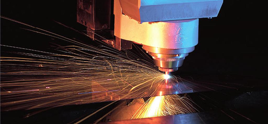


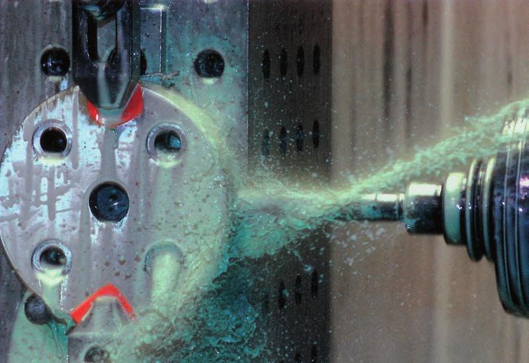


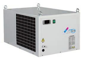

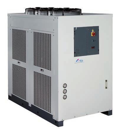

135


136
Cooling systems for electrical enclosures
 Cooling systems for electrical enclosures C17000017R07 CONTENTS There is a TEX answer to all cooling needs SKY Cooling units for door or wall mounting Page EGO Cooling units for door or wall mounting Page
WATER COOLED HEAT PUMP VERTICAL UNIT CONSOLE TYPE OR RECESSED
 EQV R-407C WATER COOLED HEAT PUMP VERTICAL UNIT CONSOLE TYPE OR RECESSED Size Cooling Heating [kw] [kw] 5 1,9 2,2 7 2,4 2,5 9 2,6 2,5 15 3,3 3,2 17 3,7 3,7 REPLACE: BT02E008GB-01 The Versatemp EQV units
Rotary Screw Compressors. ASK Series With the world-renowned SIGMA PROFILE Flow rate 0.79 to 4.65 m³/min, Pressure 5.5 to 15 bar.
 Rotary Screw Compressors ASK Series With the world-renowned SIGMA PROFILE Flow rate 0.79 to 4.65 m³/min, Pressure 5.5 to 15 bar www.kaeser.com ASK series ASK Maximum performance Discerning users expect
30GH Air-Cooled Liquid Chillers 30GH Nominal cooling capacity kw
 Air-Cooled Liquid Chillers Nominal cooling capacity 21-94 kw Carrier is participating in the Eurovent Certification Programme. Products are as listed in the Eurovent Directory of Certified Products. The
Industrial cooling systems LT
 Industrial cooling systems LT 01 Industrial cooling and heating. Partner of the industry for over 40 years. Since 1971 DELTATHERM has belonged to Hirmer GmbH, a family business with its headquarters in
SPECTRACOOL Indoor & Outdoor Air Conditioners
 Product Overview : SPECTRACOOL Indoor & Outdoor Air Conditioners G52 Indoor Model G57 Outdoor Model 18 Product Overview : Makes electronics cooling easier, so you can go about your business SPECTRACOOL
Room sealed circuit appliance sold without the terminal or the combustion air supply and exhausted gas ducts. TYPE C 63 TYPE B TYPE B 23
 Room sealed circuit appliance sold without the terminal or the combustion air supply and exhausted gas ducts. TYPE C 63 TYPE B Type B 23 on the wall Ø 80 duct, available in the following lengths: 1000,
VA G 052 S
 763.576.3200 SPEC-00746 D763.422.2211 COOLING SEALED ENCLOSURE COOLING AIR CONDITIONERS Sealed Enclosure Cooling Air Conditioners V-SERIES COMPACT AIR CONDITIONERS VA06 Indoor Model 400 and 600 Watts INDUSTRY
30HX GLOBAL CHILLER LIQUID CHILLER IN HARMONY WITH THE ENVIRONMENT
 GLOBAL CHILLER TM LIQUID CHILLER 30HX IN HARMONY WITH THE ENVIRONMENT GLOBAL CHILLER 30HX ADVANCED ULTIMATE RELIABILITY COMPACT SIZE - HIGH PERFORMANCE PRO More than 50000 Carrier screw compressors sold
GENESIS Indoor Air Conditioners
 Product Overview : Indoor Air Conditioners M28 Model M52 460 Volt 3-Phase Model M17 Model 68 68 Product Overview : The specifier s choice for cooling industrial process controls Indoor Air Conditioners
SPECTRACOOL Indoor & Outdoor Air Conditioners
 PH FX ( Product Overview : SPECTRACOOL Indoor & Outdoor Air Conditioners G52 Indoor Model G57 Outdoor Model G28 Indoor Model 18 18 Product Overview : Makes electronics cooling easier, so you can go about
Outdoor Enclosures. Outdoor Enclosures Protected like a bunker for all harsh environments
 Outdoor Enclosures Outdoor Enclosures Protected like a bunker for all harsh environments sales@mcldatasolutions.co.uk +44(0)1702 443810 mcldatasolutions.co.uk Outdoor enclosures and climate control components
Rotary Screw Compressors. ASK Series With the world-renowned SIGMA PROFILE Flow rate 0.79 to 4.65 m³/min, Pressure 5.5 to 15 bar COMPRESSORS
 COMPRESSORS Rotary Screw Compressors ASK Series With the world-renowned SIGMA PROFILE Flow rate 0.79 to 4.65 m³/min, Pressure 5.5 to 15 bar www.kaeser.com ASK series ASK Maximum performance Powerful and
G /6000 BTU/Hr. 1172/1758 Watt. Specifications. Finish. Notes
 Spec-728 CPH FX ( McLean Electronics Cooling Sealed Enclosure Cooling McLean Electronics Cooling: Sealed Enclosure Cooling SPECTRACOOL Indoor/Outdoor G57 2 BTU/Hr. 5861 Watt G52 8/12 BTU/Hr. 23/35 Watt
Hyperchill. water chillers
 Hyperchill water chillers HYPERCHILL: PRECISION CHILLED WATER Hiross Hyperchill water chillers celebrate a presence of over 30 years on the industrial chiller market. This experience has led to a range
precision controlled industrial process chillers cooling capacity: ,255,668 BTU /hr ( tons) improved productivity & reduced costs
 improved productivity & reduced costs") next generation C precision controlled industrial process chillers cooling capacity: 6824 -,255,668 BTU /hr (0.6-04.6 tons) cooling capacity: 6,824 -,254,303 BTU/hr (0.6-04.5 tons) precision controlled
next generation C precision controlled industrial process chillers cooling capacity: 6824 -,255,668 BTU /hr (0.6-04.6 tons) cooling capacity: 6,824 -,254,303 BTU/hr (0.6-04.5 tons) precision controlled
Eldon Product Overview
 Eldon Product Overview Product overview Floor Standing Enclosures page 4 Thermal Management page 32 Human Machine Interface page 26 Wall Mounted Enclosures page 12 Accessories page 38 Terminal Boxes page
Cabinet Cooler Systems
 Cooler Systems Cooler Systems Stop electronic control downtime due to heat, dirt, and moisture! maintain NEMA 4, 4X, and 12 integrity. All are and compliant! What is an EXAIR Cooler System? A low cost,
F Series - Refrigeration dryers
 F Series - Refrigeration dryers Quality compressed Air Flows from 0,38 to 110 m 3 /min QUALITY, DRY COMPRESSED AIR: THE EFFECTS: Considerably reduced production costs. Circuit protected against corrosion.
Top-Mount Air Conditioners
 Product Overview Top-Mount Air Conditioners MHB11 Model 92 92 Product Overview The perfect cooling solution when side-mount air conditioning is not an option Top-Mount Air Conditioners PRODUCT OVERVIEW
N Volt 1800 BTU/Hr. 527 Watt. Specifications. Finish. Notes
 Spec-75 A( McLean Electronics Cooling Sealed Enclosure Cooling McLean Electronics Cooling: Sealed Enclosure Cooling SPECTRACOOL Compact Indoor N17 115/23 Volt 1 BTU/Hr. Watt N17 46 Volt 18 BTU/Hr. 527
Air Conditioning THERMAL MANAGEMENT SOLUTIONS FOR ELECTRICAL ENCLOSURES
 Air Conditioning THERMAL MANAGEMENT SOLUTIONS FOR ELECTRICAL ENCLOSURES AIR CONDITIONING Air Conditioning Models and power The range of air conditioners ALFA ELECTRIC includes several productions depending
SPECTRACOOL INDOOR/OUTDOOR
 SPEC-728 E SEALED ENCLOSURE AIR CONDITIONERS SEALED ENCLOSURE AIR CONDITIONERS SPECTRACOOL INDOOR/OUTDOOR G57 2 BTU/Hr. 5861 Watt G52 8/12 BTU/Hr. 23/35 Watt G28 4/6 BTU/Hr. 1172/ Watt Clean AirFlow Ambient
Cold Energy Saver. Thermal Mass Cycling Refrigerated Air Dryers ( scfm)
") aerospace climate control electromechanical filtration fluid & gas handling hydraulics pneumatics process control sealing & shielding Cold Energy Saver Thermal Mass Cycling Refrigerated Air Dryers (200-1000
aerospace climate control electromechanical filtration fluid & gas handling hydraulics pneumatics process control sealing & shielding Cold Energy Saver Thermal Mass Cycling Refrigerated Air Dryers (200-1000
MAC-A R410A Series Air cooled Modular Chiller
 Catalogue MAC R410A 2011(60Hz) MAC-A R410A Series Air cooled Modular Chiller Model: Refrigerant: Co ling Capacity: MAC210A5 R410A 72kW Overview Based on the successful McQuay air-cooled modular chiller,
CT EN rel. 10/09 Copyright Eliwell Controls s.r.l All rights reserved
 Eliwell Controls Srl Via dell Industria, 15 Z. I. Paludi 32010 Pieve d Alpago (BL) - Italy Telephone +39 0437 986 111 Facsimile +39 0437 989 066 Sales: +39 0437 986 100 (Italy) +39 0437 986 200 (other
MAC-D R410A Series Air-cooled Modular Chiller/Heat pump
 Catalogue MAC-D-2013 (50Hz) MAC-D R410A Series Air-cooled Modular Chiller/Heat pump Model: Refrigerant: Cooling Capacity: Heating Capacity: MAC210D5-MAC1680D5 MAC230D5-MAC1840D5 MAC210DR5-MAC1680DR5 MAC230DR5-MAC1840DR5
Innovative air conditioning
 Innovative air conditioning No external condensers or pipework Easy installation Discreet external grilles Quiet, high efficiency operation In exclusive partnership with Olimpia Splendid, one of Europe
5736 N. Michigan Road Indianapolis, IN 46228
 763.576.3200 SPEC-00728 H763.422.2211 COOLING SEALED ENCLOSURE COOLING AIR CONDITIONERS Sealed Enclosure Cooling Air Conditioners SPECTRACOOL INDOOR/OUTDOOR G57 BTU/Hr. Watt G52 / BTU/Hr. 2300/3500 Watt
5736 N. Michigan Road Indianapolis, IN 46228
 763.576.32 SPEC-728 H763.422.2211 COOLING SEALED ENCLOSURE COOLING AIR CONDITIONERS Sealed Enclosure Cooling Air Conditioners SPECTRACOOL INDOOR/OUTDOOR G57 2 BTU/Hr. 5861 Watt G52 8/12 BTU/Hr. 23/35 Watt
INDUSTRIAL APPLICATIONS THE PROMISE THE PROOF HEATEX AIR-TO-AIR HEAT EXCHANGERS
 IA INDUSTRIAL APPLICATIONS THE PROMISE THE PROOF HEATEX AIR-TO-AIR HEAT EXCHANGERS INDUSTRIAL DEHUMIDIFICATION AND ENERGY RECOVERY SOLUTIONS Many industrial processes generate large amounts of hot and
30RB Air-Cooled Liquid Chillers. Nominal cooling capacity 8-14 kw. Features. Quiet operation
 Air-Cooled Liquid Chillers www.eurovent-certification.com www.certiflash.com Quality Management Systems 0RB 008-05 Nominal cooling capacity 8- The new generation of Aquasnap liquid chillers was designed
PROAIR Harsh Environment/Wash Down Air Conditioners
 PH FX ( Product Overview McLean Cooling Technology: Air Conditioners: Harsh Environment/Wash Down Air Conditioners CR23 CR23st CR43st CR29 102 Product Overview : The ultimate in protective cooling for
All series is using Hitachi scroll compressor, low vibration and high efficiency. Internal thermostat embedded compressors, and it can react quickly.
 HITACHI proudly presents to our customers this wide range of split system air conditioners, from 4HP to 20 HP which is designed for high and medium outdoor temperature and comply with almost any types
T BTU/Hr. 234 Watts. T BTU/Hr. 586 Watts. Air Conditioners
 763.576.32 Spec-733 C763.422.2211 Sealed Enclosure Air Conditioners Sealed Enclosure Air Conditioners T-SERIES Compact Outdoor T15 8 BTU/Hr. 234 Watts T2 2 BTU/Hr. 586 Watts INDUSTRY STANDARDS UL/cUL Listed;
VA G 052 S VA08 Indoor Model 1200, 1500 and 2000 Watts. Sealed Enclosure Cooling Air Conditioners
 V-Series Mid-Size Air Conditioners (Now done by MGDC) VA08 Indoor Model 1200, 1500 and 2000 Watts INDUSTRY STANDARDS IP 56 Internal Air Loop IP 34 External Air Loop APPLICATION Industrial drive enclosures
next DX.U.S* 052.Z2.H6.DC
 next DX.U.S* 05.Z.H6.DC GENERAL CHARACTERISTICS Air conditioning unit with remote air cooled condenser, for computer rooms, any high-tech facility and offices. Units can run non-stop at 4x65 hours a year.
G /6000 BTU/Hr. 1172/1758 Watt
 Spec-728 E Sealed Enclosure Air Conditioners Sealed Enclosure Air Conditioners SPECTRACOOL Indoor/Outdoor G57 2 BTU/Hr. 5861 Watt G52 8/12 BTU/Hr. 23/35 Watt G28 4/6 BTU/Hr. 1172/ Watt Clean AirFlow Ambient
GENERAL INFORMATIONS
 GENERAL INFORMATIONS Devices only operate in cooling mode. Enviromental-friendly R407c coolant is utilized in standard products. The system can be created with various coolants depending on the water temperature
N Volt 1800 BTU/Hr. 527 Watt
 763.576.32 SPEC-75 F763.422.2211 COOLING SEALED ENCLOSURE COOLING AIR CONDITIONERS SPECTRACOOL COMPACT INDOOR N17 115/23 Volt BTU/Hr. Watt N17 46 Volt 18 BTU/Hr. 527 Watt INDUSTRY STANDARDS UL/cUL Listed;
Ultimate energy saving technology
 Ultimate energy saving technology CWT Chiller Series CWt purestream series water chillers The new CWT Purestream chiller range is specifically designed to meet the stringent cooling requirements of today
KELVIN BELT-DRIVEN ROTARY SCREW AIR STATION, FIXED OR VARIABLE SPEED. from 7.5 to 22 kw from 8 to 13 bar
 KELVIN BELT-DRIVEN ROTARY SCREW AIR STATION, FIXED OR VARIABLE SPEED from 7.5 to 22 kw from 8 to 13 bar KELVIN Belt-driven rotary screw compressors A true integrated air station COMPRESSOR AIR RECEIVER
N Volt 1800 BTU/Hr. 527 Watt
 Spec-75 B Sealed Enclosure Air Conditioners Sealed Enclosure Air Conditioners SPECTRACOOL Compact Indoor N17 115/23 Volt 1 BTU/Hr. Watt N17 46 Volt 18 BTU/Hr. 527 Watt INDUSTRY STANDARDS UL/cUL Listed;
Drying in series deserves the right control Dryers of the GDZ Series
 Drying in series deserves the right control Dryers of the GDZ Series Tutti i modelli di design delle apparecchiature Grandimpianti I.L.E.sono depositati GDZ. Series production under control Optimises costs,
Indoor and Outdoor Enclosures Outdoor Nema 3, 3R, 4, 4X Cabinet Enclosures LTE 4G Wimax Telecom Security Traffic
 Spec-00698 APH FX ( Protective Cooling Air Conditioners N28 Narrow Indoor/Outdoor Base Models Features R407c and R134a earth-friendly refrigerants and RoHS compliant Models for 115, 230 AC volt power input
CONVENIENT FEATURES ...MORE PERFORMANCE LESS... SPACE ENERGY NOISE G-TEC BELT-DRIVEN ROTARY SCREW AIR STATION. 7.5 to 22 kw 8 to 13 bar
 LESS... SPACE ENERGY NOISE...MORE CONVENIENT FEATURES PERFORMANCE G-TEC BELT-DRIVEN ROTARY SCREW AIR STATION 7.5 to 22 kw 8 to 13 bar G-TEC Belt-driven rotary screw compressors A true integrated air station
Rotary Screw Compressors ASD Series
 www.hpccompressors.co.uk Rotary Screw Compressors ASD Series With the world-renowned SIGMA PROFILE Free air delivery 0.87 to 6.26 m³/min, Pressure 5.5 15 bar ASD series Service-friendly design ASD: Long-term
EJBX. Ex d. AISI 316L stainless steel. - Zone 1, 2, 21, 22 - Group IIB+H2 - Stainless steel junction boxes - Choice of 13 sizes - IP 66 / 67
 Ex d EJBX AISI 316L stainless steel - Zone 1, 2, 21, 22 - Group IIB+H2 - Stainless steel junction boxes - Choice of 13 sizes - IP 66 / 67 Quartz sand blasting Warning labels Mounting bracket Silicone gasket
VA G 052 S VA08 Indoor Model 1200, 1500 and 2000 Watts. Sealed Enclosure Cooling Air Conditioners
 763.576.3200 SPEC-00747 D763.422.2211 COOLING SEALED ENCLOSURE COOLING AIR CONDITIONERS Sealed Enclosure Cooling Air Conditioners V-SERIES MID-SIZE AIR CONDITIONERS VA08 Indoor Model 1200, 1500 and 2000
G /6000 BTU/Hr. 1172/1758 Watt
 SPECTRACOOL Indoor/Outdoor G57 2 BTU/Hr. 5861 Watt G52 8/12 BTU/Hr. 23/35 Watt G28 4/6 BTU/Hr. 1172/ Watt Clean AirFlow Ambient AirFlow INDUSTRY STANDARDS UL/cUL Listed; Type 12, 3R, 4; 4X optional; File
Cooling unit Mechanical control
 ClimaSys CU Cooling unit Mechanical control Top-mounting models, ref. NSYCU760W2VR- NSYCU10W2VR- NSYCU1460W2VR J 26 A B 8 K 2 0 C D E H F G Cut-out template for top mounting without intermediate frame.
air handling units AT THE LEADING EDGE OF AIR FLOW
 air handling units floway AT THE LEADING EDGE OF AIR FLOW floway: Delivering Advanced Air Flow and Full Satisfaction Energy recovery was at the heart of CIAT new Floway offering. The range proposes compact
AQUASNAP JUNIOR 30RHV
 High-Efficiency Air-To-Water Heat Pumps Carrier is participating in the Eurovent Certification Programme. Products are as listed in the Eurovent Directory of Certified Products. AQUASNAP JUNIOR 3RHV 6-11
ULTIMATE ENERGY SAVING TECHNOLOGY
 ULTIMATE ENERGY SAVING TECHNOLOGY CWM CHILLER SERIES CWM PURESTREAM SERIES WATER CHILLERS The new CWM Purestream chiller range is specifically designed to meet the stringent cooling requirements of today
COMPANY PROFILE 2016
 COMPANY PROFILE 2016 Since its birth in 1991 RefComp brand has been distinguishing itself for its innovative ability initially for the piston, then for the screw. RefComp was the first Italian company
Energy-Saving Refrigeration Dryers SECOTEC
 COMPRESSEURS Energy-Saving Refrigeration Dryers SECOTEC TA to TD series The savings specialists with stable pressure dew point Flow rate 0.60 to 8.25 m³/min, pressure 3 to 16 bar www.kaeser.com SECOTEC
With the world-renowned SIGMA PROFILE
 www.kaeser.com Rotary Screw Compressors BSD/CSD/CSDX T SFC Series With the world-renowned SIGMA PROFILE Free air delivery 0.87 to 16.10 m³/min, Pressures 5.5 to 15 11 What do you look for in a compressor
CHGV AIR COOLED WATER CHILLER WITH HYDRAULIC EQUIPMENT AIR / WATER 21 to 39 kw
 TECHNICAL INSTRUCTIONS CHGV AIR COOLED WATER CHILLER WITH HYDRAULIC EQUIPMENT AIR / WATER 21 to 39 kw CHGV 22 CHGV 2 CHGV 32 CHGV 40 PHRV heat pump model also available September 2007 10 12 11 - GB - 02
CHGV AIR COOLED WATER CHILLER WITH HYDRAULIC EQUIPMENT AIR / WATER 47 to 78 kw
 TECHNICAL INSTRUCTIONS CHGV AIR COOLED WATER CHILLER WITH HYDRAULIC EQUIPMENT AIR / WATER 47 to 78 kw CHGV 50 CHGV 64 CHGV 72 CHGV 80 PHRV heat pump model also available November 2007 10 12 167 - GB -
Fan-and-filter units 4.3. Features. Fast assembly. Application diversity and functions
 Fan-and-filter units Features Fan-and-filter units are ideal for dissipating heat loads costeffectively. The pre-requisite is that the ambient air must be relatively clean and with a temperature below
Application tips. Cooling capacity W
 Cooling capacity 3850 pplication tips hen choosing the cooling unit maintain a safety margin of at least % on the rated power considering the most difficult conditions it will have to work in. Seal the
Table of Content
 Table of Content 43402001 1. User manual... 2 2. Legal regulations... 2 3. Safety instructions... 3 4. Technical information... 4 5. Functional principle... 5 6. Technical data... 6 7. Mounting... 7 8.
Refrigerated Compressed Air Dryers
 10 to 500 SCFM 17 to 850 M 3 /H Refrigerated Compressed Air Dryers HG, HGE & HGN VALUE SERIES Reliable Operation... Customers around the world have relied on Deltech for great value in air treatment solutions.
ERGONOMICS AND CLEANING EXPERIENCE AND PASSION AT YOUR SERVICE
 9 7 ERGONOMICS AND CLEANING The octagonal knobs, elegant and easy to operate, are located on an inclined panel for ease of use and visual appeal. The work tops are designed to allow use of the entire
Product is subject to and complies with Regulation (UE) N.327/2011. cert. n Fan Coil Unit Cassette SkyStar Jumbo ECM. technical catalogue
 N.327/2011. cert. n Fan Coil Unit Cassette SkyStar Jumbo ECM. technical catalogue") cert. n. 0545 Product is subject to and complies with Regulation (UE) N.327/2011 Fan Coil Unit Cassette SkyStar Jumbo ECM technical catalogue SkyStar Jumbo ECM Table of contents SkyStar Jumbo ECM TABLE
cert. n. 0545 Product is subject to and complies with Regulation (UE) N.327/2011 Fan Coil Unit Cassette SkyStar Jumbo ECM technical catalogue SkyStar Jumbo ECM Table of contents SkyStar Jumbo ECM TABLE
Bernstein product overview
 ITC Electrical Components is proud to announce that BERNSTEIN AG of Porta Westfalica, Germany has appointed ITC as their exclusive Canadian distributor. Bernstein product overview Sensor Systems Inductive
IEC THE PROMISE THE PROOF HEATEX INDIRECT EVAPORATIVE COOLING AIR-TO-AIR HEAT EXCHANGERS
 IEC INDIRECT EVAPORATIVE COOLING THE PROMISE THE PROOF HEATEX AIR-TO-AIR HEAT EXCHANGERS 2 INCREASED ENERGY SAVINGS COMPARED TO CONVENTIONAL COOLING SYSTEMS Indirect evaporative cooling uses heat exchangers
PRODUCT DATA COMPACT P - SERIES BY NILAN. Sanitary hot water production. Heating. Ventilation < 300 m 3 /h. Passive heat recovery.
 PRODUCT DATA COMPACT P - SERIES BY NILAN Domestic Passive heat recovery Active heat recovery Ventilation < 300 m 3 /h Comfort heating Comfort cooling Sanitary hot water production Heating THE VENTILATION
TECHNICAL MANUAL FOR AIR-COOLED CONDENSING UNITS MTE
 GB TECHNICAL MANUAL FOR AIR-COOLED CONDENSING UNITS MTE 5 kw - 213 kw TABLE OF CONTENTS 1 The series...4 2 Constructive features...4 3 Layout of components...5 4 Models and configurations...13 5 Technical
COOLflow 4E PRODUCT RANGE
 COOLflow 4E PRODUCT RANGE FREE AIR COOLING FROM THE FREE AIR SPECIALISTS GUARANTEED TO SIGNIFICANTLY REDUCE CARBON EMISSIONS & DELIVER ENERGY SPEND SAVINGS OF UP TO 95% The COOLflow 4E range has been developed
CHAPTER12. Thermal Management. Featured Products in this Chapter. Outdoor Air Conditioners T15, T20 and T29 Series 800-4,000 BTU/Hr. P.
 PH FX (763) 422-2600 422-2211 : CHAPTER12 Thermal Management Featured Products in this Chapter Outdoor Air Conditioners T15, T20 and T29 Series 800-4,000 BTU/Hr. P. 1156 Outdoor Air Conditioners T43, T50
Quality Enclosures. Service Excellence.
 Cooling Products General Information...5 General Selection Considerations...5 Sizing an Air Conditioner...6 General Specifications for Air Conditioners...7 Side Mounting DTS Series Air Conditioners 1200
Rotary Screw Compressors. SK Series With the world-renowned SIGMA PROFILE Flow rate 0.53 to 2.70 m³/min, Pressure 5.5 to 15 bar
 Rotary Screw Compressors SK Series With the world-renowned SIGMA PROFILE Flow rate 0.53 to 2.70 m³/min, Pressure 5.5 to bar www.hpccompressors.co.uk SK series Quiet, dependable performance Discerning compressed
30HXC - 50 HZ. Water-Cooled Screw Compressor Liquid Chillers. Nominal cooling capacity kw
 Water-Cooled Screw Compressor Liquid Chillers Carrier is participating in the Eurovent Certification Programme. Products are as listed in the Eurovent Directory of Certified Products. 0HC - 50 HZ Nominal
R 407 C. > in industrial application. Always very much appreciated for special installations these units shown their powers :
 SINGLEPACKAGE CONSOLE UNITS, MONOSPLIT, AIR CONDENSING UNITS APPLICATIONS COMMERCIAL SECTOR CONSOLE UNITS AIR CONDENSING UNITS Always very much appreciated for special installations these units shown their
Atlas Copco. Oil-injected Rotary Screw Compressors Variable Speed Drive + (7-15 kw/10-20 hp)
") Atlas Copco Oil-injected Rotary Screw Compressors Variable Speed Drive + (7-15 kw/10-20 hp) Extreme savings No idling time Silent operation Small footprint The new revolutionary compressor from Atlas Copco
Atlas Copco Oil-injected Rotary Screw Compressors Variable Speed Drive + (7-15 kw/10-20 hp) Extreme savings No idling time Silent operation Small footprint The new revolutionary compressor from Atlas Copco
Revolutionary ETS Colibri valves Engineered to give you maximum flexibility and dependability
 Revolutionary ETS Colibri valves Engineered to give you maximum flexibility and dependability ETS Colibri brings to the market one of a kind, uniquely designed electric expansion valve. Innovative Design
Air to water Heat Pump System
 Air to water Heat Pump System 2 The heating and cooling systems of the future! A step in the right direction of reducing pollution and CO₂ emissions The increase of CO₂ and other green house gases is a
Refrigerated Compressed Air Dryers
 10 to 1200 SCFM 17 to 2040 M 3 /H Refrigerated Compressed Air Dryers HG, HGE & HGEN VALUE SERIES Reliable Operation... Customers around the world have relied on Deltech for great value in air treatment
Safe Enclosure Cooling
 Safe Enclosure Cooling Heat Exchangers 2017 www.seifertsystems.com Table of Contents Page Product Overview 3 Air / water heat exchangers 4-18 Air / air heat exchangers 19-25 Thermal Management solutions
Power. Average noise level (DIN EN ISO 4871)
") 21m 3 /h to 102m 3 /h Very low noise Minimal depth in Functional design Time-saving installation Filter fans are used to provide an optimum climate in s. The interior temperature of an can be reduced by
21m 3 /h to 102m 3 /h Very low noise Minimal depth in Functional design Time-saving installation Filter fans are used to provide an optimum climate in s. The interior temperature of an can be reduced by
F o r Te x t i l e I n d u s t r y
 For Textile Industry Applications : Compressed air is a vital part in textile industry in all phases of spinning, weaving, loom and knitting. The quality of compressed air required to be on various specification
WATER TO AIR DUCTABLE INDOOR HORIZONTAL HEAT PUMP
 EVH R-407C WATER TO AIR DUCTABLE INDOOR HORIZONTAL HEAT PUMP Size Cooling Heating [kw] [kw] 7 2.0 1.9 11 2.6 2.5 15 3.9 3.3 5.2 5.5 25 7.3 6.7 31 8.9 8.4 41 10.7 9.8 REPLACE: BT02E009GB-01 The Versatemp
Extreme industrial environments Air/water heat exchangers (roof-mounted, wall-mounted) Recooling system
 Recooling system") 3 Extreme industrial environments Air/water heat exchangers (roof-mounted, wall-mounted) Recooling system 3 04 eat exchangers One concept, two systems with very different operating methods Air/water heat
3 Extreme industrial environments Air/water heat exchangers (roof-mounted, wall-mounted) Recooling system 3 04 eat exchangers One concept, two systems with very different operating methods Air/water heat
AQUASNAP AIR CONDITIONING MADE SIMPLE 30RA/30RH AQUASNAP LIQUID CHILLERS HEAT PUMPS
 AQUASNAP TM AQUASNAP LIQUID CHILLERS HEAT PUMPS 30RA/30RH AIR CONDITIONING MADE SIMPLE BOLT DOWN, PLUG IN... READY THE IDEAL ALL-IN-ONE SOLUTION With the Aquasnap everything is included to reduce the complexity
Condensing Units CUS 15-60
 Condensing Units CUS 15-60 General Description UNIT IDENTIFICATION AIR COOLED CONDENSING UNIT CUS... Condensing Unit with Propeller Fan and Scroll Compressor 15-60... Model Size D... Double Circuit e.g....
your comfort. our world. Altherma Flex Type Renewable heat pump system for every environment
 your comfort. our world. Altherma Flex Type Renewable heat pump system for every environment Outdoor One or more indoor or outdoor units Indoor 1 Domestic hot water 2 Heating 3 Cooling Daikin Altherma
DEi COMPRESSED AIR & GAS TREATMENT. Purifying your compressed air, increasing your efficiency.
 COMPRESSED AIR & GAS TREATMENT DEi Refrigeration dryers with Energy Saving Impulse Technology and Thermal Mass Nominal air flow 0,3-32,0 m³/min. Purifying your compressed air, increasing your efficiency.
Thermal Management INDEX. Management. Thermal TM-1
 Heat builds up rapidly in enclosed environments, compromising the performance and life span of equipment. Like insurance for your electronics, effective thermal management maximizes the efficiency and
Refrigeration dryers with Energy Saving Impulse Technology and Thermal Mass 0,3-27,0 m³/min Purifying your compressed air, increasing your efficiency.
 Refrigeration dryers with Energy Saving Impulse Technology and Thermal Mass 0,3-27,0 m³/min Purifying your compressed air, increasing your efficiency. Refrigeration dryers with Energy Saving Impulse Technology
Heat Cool system. Take control of your pool heating and cooling with the Calorex 34 and new Pro-Pac ranges
 Heat Cool system Take control of your pool heating and cooling with the Calorex 34 and new Pro-Pac ranges Full range of heat pumps for indoor and outdoor use Zero ozone depleting refrigerant Specifically
PURESTREAM CHILL-CUBE TM BY FRIULAIR
 PURESTREAM CHILL-CUBE TM BY FRIULAIR Air-cooled water chiller Cooling capacity from 0.5 to 6 tons R407C Refrigerant QPS Inspection label certified to CSA standards 2 Year parts warranty The QBE Chill-Cube
Reinventing Energy Efficiency WARMNESS.
 Residential WATER2WATER WT SERIES Reinventing Energy Efficiency WARMNESS www.fhp-mfg.com Environmental stewardship is a core philosophy for FHP Manufacturing from design to production to the reduction
A cast iron case for our modular motors: High-voltage motors H-compact PLUS
 A cast iron case for our modular motors: High-voltage motors H-compact PLUS Visit us in the Internet under "http://www.ad.siemens.de" Automation and Drives Group Large Machines Division P.O. Box 47 43,
30RB Air-Cooled Liquid Chillers PRODUCT SELECTION DATA. Easy and fast installation. Compact, reliable and efficient
 PRODUCT SELECTION DATA Easy and fast installation Compact, reliable and efficient Class A variable speed circulator available Air-Cooled Liquid Chillers 0RB 008-015 CARRIER participates in the ECP programme
AIR CONDITIONING HOLIDAY. Elite W A R R A N T Y
 AIR CONDITIONING HOLIDAY Elite 3 YEAR W A R R A N T Y AIR CONDITIONER + DEHUMIDIFIER IN A SINGLE UNIT Elite by name and elite by nature, this unit combines a true air conditioner and a true dehumidifier
stego_katalog_2008_en.qxp:englisch :09 Uhr Seite 1 Product Catalogue
 Product Catalogue Thermal Management Products & Accessories from STEGO successfully used worldwide for control panels and enclosures for traffic control and monitoring systems in the transport industry
WHIRLPOOL LAUNDRY 02/
 WHIRLPOOL LAUNDRY 02/2011 www.whirlpool-professional.com WHIRLPOOL LAUNDRY The Whirlpool professional range of laundry appliances addresses the needs of small and large laundry facilities alike. The washers,
Reliability & efficiency without compromise
 01 GB Reliability & efficiency without compromise Rotary Screw Compressors Premium compressor design L50, L80, L140 First-class efficiency Efficiency Leader The L-Series from CompAir Well known in the
Conditioning your ambient, maximising your comfort.
 Centrifugal fan coils for surface mounting or recessed installation. Cooling capacities from 0,6 to 7,6 kw and heating capacity from 0,8 to 9 kw. Air flow from 100 to 1500 m 3 /h. Cassette with radial