E26 CONVECTION OVEN SERVICE MANUAL. Revision 1/F
|
|
|
- Patricia Garrett
- 5 years ago
- Views:
Transcription
1


2 E26 CONVECTION OVEN SERVICE MANUAL -1-
3 WARNING: ALL INSTALLATION AND SERVICE REPAIR WORK MUST BE CARRIED OUT BY QUALIFIED PERSONS ONLY. -2-
4 CONTENTS This manual is designed to take a more in depth look at the E26 convection oven for the purpose of making the unit more understandable to service people. There are settings explained in this manual that should never require to be adjusted, but for completeness and those special cases where these settings are required to change, this manual gives a full explanation as to how, and what effects will result. SECTION PAGE NO. 1. SPECIFICATIONS INSTALLATION OPERATION Description of Controls 3.2 Explanation of Control System 4. MAINTENANCE Cleaning 4.2 Routine Procedures 5. TROUBLE SHOOTING GUIDE SERVICE PROCEDURES Fault Diagnosis 6.2 Access 6.3 Replacement 6.4 Adjustment / Calibration 7. ELECTRICAL SCHEMATIC ELECTRICAL WIRING DIAGRAM SPARE PARTS ACCESSORIES / OPTIONS PARTS DIAGRAM Main Assembly 11.2 Control Panel Assembly 12. SERVICE CONTACTS...30 IMPORTANT: MAKING ALTERATIONS MAY VOID WARRANTIES AND APPROVALS. -3-
5 -4-
6 1. SPECIFICATIONS MODEL: E (34.9) 668 (26.3) 430 (16.9) 791 (31.1) FRONT 124 (4.9) 45 (1.75) 179 (7.0) SIDE 395 (15.5) PLAN LEGEND - Electrical connection entry point Dimensions shown in millimetres. Dimensions in inches shown in brackets. -5-
7 LOCATION To ensure correct ventilation for the motor and controls the following minimum installation clearances are to be adhered to: Rear 25mm / 1 Left-hand side 25mm / 1 Right-hand side 25mm / 1 OVEN INTERNAL DIMENSIONS Width 635 mm / 25 Height 270 mm / 10.5 Depth 500 mm / 19.5 Oven Volume 0.14 m³ / 5.0ft³ OVEN RACK SIZE Width 600 mm Depth: 400 mm ELECTRICAL SUPPLY SPECIFICATION OPTIONS 220Vac, 50/60Hz, 11A, 220V Vac, 50Hz, 10A, 240V ELECTRICAL PLUG SPECIFICATION REQUIREMENTS Australia 3-pin 250V 15A, AS/NZ 3112 New Zealand 3-pin 250V 15A, AS/NZ 3112 United Kingdom 3-pin 250V 13A fused, BS 1363A Other Countries 3-pin 250V 13A minimum, type to meet country standards -6-

8 2. INSTALLATION WARNING: THIS APPLIANCE MUST BE GROUNDED. WARNING: ALL INSTALLATION AND SERVICE REPAIR WORK MUST BE CARRIED OUT BY QUALIFIED PERSONS ONLY. It is most important that the oven is installed correctly and that the operation is correct before use. Installation shall comply with local electrical, health and safety requirements. BEFORE CONNECTION TO POWER SUPPLY Unpack and check unit for damage and report any damage to the carrier and dealer. Report any deficiencies to your dealer. Check that the available power supply is correct to that shown on the rating plate located on the righthand side panel. E26 220Vac, 50/60Hz, 11A, 220V Vac, 50Hz, 10A, 240V LOCATION To ensure correct ventilation for the motor, and controls the following minimum installation clearances are to be adhered to: ELECTRICAL CONNECTION E26 convection ovens are supplied with pre-fitted cords. Ensure unit is fitted with the correct cord and plug for the installation. Refer specifications section. Should changing of the cord be necessary, gain access to the electrical connection terminal block, grounding lug, and strain relief by removing the back panel (four screws). Figure 2.1 RATING PLATE LOCATION The rating plate for the E26 convection oven is located at the bottom left corner of the RH side panel. Rear 25mm / 1 Left-hand side 25mm / 1 Right-hand side 25mm / 1 IMPORTANT: THE OVEN VENT LOCATED ON THE CABINET TOP MUST NEVER BE OBSTRUCTED. Position the oven in its allocated working position. Use a spirit level to ensure the oven is level from side to side and front to back. (If this is not carried out, uneven cooking could occur). The feet used with bench mounting are adjustable and will require adjusting in levelling the unit. It should be positioned so the operating panel and oven shelves are easily reachable for loading and unloading. Figure 2.2 Rating Plate BEFORE USE Operate the oven for about 1 hour at 200 C (400 F) to remove any fumes or odours which may be present. -7-
. 1 2. THERMOSTAT Temperature range 50-250 C. Light illuminates when elements are cycling ON to maintain set temperature.")
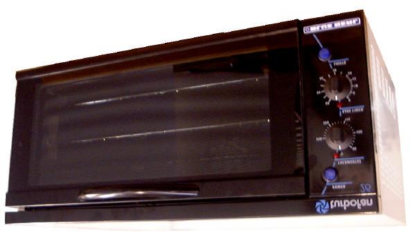
9 3. OPERATION NOTE: A full user s operation manual is supplied with the product and can be used for further referencing of installation, operation and service. 3.1 DESCRIPTION OF CONTROLS - E26 1. POWER Depress to switch power on or off (switch illuminates when power is on) THERMOSTAT Temperature range C. Light illuminates when elements are cycling ON to maintain set temperature. 3. BAKE TIMER 1 Hour bake timer. (Light illuminates when time up (0) reached, and buzzer sounds) LIGHT SWITCH Push switch to activate light. (Light illuminates while button depressed)
10 3.2 EXPLANATION OF CONTROL SYSTEM The E26 Turbofan convection ovens feature multi-function operator controls for which a correct understanding of their operation is required before carrying out any service or fault repair work. The control device functions are explained as follows: A power switch on the control panel isolates power to all the controls of the oven. With the power switch Off all functions of the oven are inoperable. Off position, the element relies on the thermostatic control to prevent it switching on. Accordingly, if the oven temperature drops below approximately 20 C the thermostat and element may cycle on at this setting. The following Troubleshooting Guide should be used to identify any incorrect oven operation. On correct identification of the operating fault the Troubleshooting Guide will make reference to the corrective action required, or refer to the Fault Diagnosis section and/or Service section to assist in correction of the fault. With the power switch On (illuminated) power is directly supplied to the 60 minute bake timer, door microswitch, temperature control circuit, fan motor, and the light switch. The light switch will turn the oven light on when the door is closed, but only whilst the light switch is held in. The door microswitch on the E26 oven controls the oven light only. Accordingly the light will come on when the door is opened but the circulation fan and fan element will remain on. The 60 minute timer is a mechanical timer and can therefore be operated with the oven s power switch On or Off. However, only with the oven s power switch On will the switch contacts of the 60 minute timer turn on the time-up buzzer and illuminate the time-up indicator on the control panel. The buzzer and time-up indicator provide indication that the time setting has run down to zero and at this point will remain On continuously until the 60 minute timer has been manually set back to the Off (vertical) position. The 60 minute timer does not control any other part of the oven s operating system as this timer is independent of the temperature control and heating system. The temperature control of these ovens is with a capillary type thermostat which can be set to a required cooking temperature. The E26 has an element coiled around the circulation fan in the rear of the oven. Power to the element is provided directly from the thermostat. The control panel indicator light above the thermostat knob cycles on and off with the thermostat to indicate when the element is on and the oven is heating. In the -9-
11 4. MAINTENANCE WARNING: ALL INSTALLATION AND SERVICE REPAIR WORK MUST BE CARRIED OUT BY QUALIFIED PERSONS ONLY. 4.1 CLEANING WARNING: ALWAYS TURN THE POWER SUPPLY OFF BEFORE CLEANING. IMPORTANT: THIS UNIT IS NOT WATER PROOF. DO NOT USE A WATER JET SPRAY TO CLEAN INTERIOR OR EXTERIOR OF THIS UNIT. EXTERIOR Clean with a good quality stainless steel cleaning compound. Harsh abrasive cleaners may damage the surface. OVEN SEALS To remove, hold at their centre point and pull forward until they unclip. Remove side seals first, then top and bottom. The seals may be washed in the sink, but take care not to cut or damage them. To replace, ensure that the lip is facing the oven opening. Fit the top and bottom seals first, then the side seals. OVEN DOOR GLASS Clean with conventional glass cleaners 4.2 ROUTINE PROCEDURES DOOR SEALS Check for deterioration 12 months INTERIOR Ensure that the oven chamber is cool. Do not use wire brushes, steel wool or other abrasive materials. Clean the oven regularly with a good quality oven cleaner. Take care not to damage the fan or the tube at the right side of the oven which controls the thermostat. ELEMENTS Check that element resistances are correct to their ratings (refer 6.3.9) 12 months OVEN RACKS To remove, slide out to the stop position, raise the front edge up, and lift out. BOTTOM BAFFLE Slide forward and lift out. When replacing, ensure tray is pushed fully in to rear of oven. SIDE RACKS Loosen rear thumbscrew 2-3 turns. Remove front thumbscrew and pull rack forward to disengage rear screw then lift out. Replace in reverse order. FAN BAFFLE To remove, undo thumbscrew (counterclockwise rotation) at top of baffle and remove. Lift baffle out from rear of oven by tilting forward while lifting out of location studs at baffle base. Replace in reverse order. -10-
12 5. TROUBLE SHOOTING WARNING: ALL INSTALLATION AND SERVICE REPAIR WORK MUST BE CARRIED OUT BY QUALIFIED PERSONS ONLY. FAULT POSSIBLE CAUSE REMEDY THE OVEN DOES NOT OPERATE / START The mains isolating switch on the wall, circuit breaker or fuses are off at the power board. Turn on. The power switch on the oven is off. Depress switch. Switch will illuminate. FAN DOESN T OPERATE OVEN LIGHT NOT ILLUMINATING - DOOR OPEN OVEN LIGHT NOT ILLUMINATING - DOOR CLOSED 60 MINUTE TIMER WILL NOT TIME DOWN 60 MINUTE TIMER INACCURATE BELOW 20 MINUTES 60 MINUTE TIMER NO TIME UP BUZZER 60 MINUTE TIMER NO TIME UP INDICATOR Incorrect electrical supply. (Refer fault diagnosis 6.1.1) Power switch on unit faulty. (Refer fault diagnosis 6.1.1) Fan motor faulty. (Refer fault diagnosis 6.1.2) Wiring. Blown bulb. No power to light. (Refer fault diagnosis 6.1.3) Blown bulb. Light switch faulty. (Refer fault diagnosis 6.1.4) Timer faulty. Timer not set correctly. Zero (time up) position not set correctly. Buzzer faulty. (Refer fault diagnosis 6.1.5) Timer not switching on buzzer. (Refer fault diagnosis 6.1.5) Indicator faulty. (Refer fault diagnosis 6.1.6) Ensure electrical supply correct. Replace. (Refer service section 6.3.4) Replace. (Refer service section ) Check and tighten any loose wiring. Replace. (Refer service section 6.3.1) Correct fault. Replace. (Refer service section 6.3.1) Replace. (Refer service section 6.3.4) Replace. (Refer service section 6.3.6) For timer settings below 20 minutes, always rotate past 20 minutes, then back to desired time. (Refer service section 6.4.3) Replace. (Refer service section 6.3.5) Replace. (Refer service section 6.3.6) Replace. (Refer service section 6.3.3) -11-
13 FAULT POSSIBLE CAUSE REMEDY NO HEAT NO TEMPERATURE CONTROL SLOW RECOVERY FAN ELEMENT NOT WORKING NO THERMOSTAT HEATING INDICATOR LIGHT DOOR DOES NOT CLOSE DOOR SEAL LEAKS No power to thermostat. (Refer fault diagnosis 6.1.7) Thermostat faulty. (Refer fault diagnosis 6.1.7) Fan element faulty (Refer fault diagnosis ) Thermostat faulty. (Refer fault diagnosis 6.1.8) Overloading of oven. Electrical supply incorrect. Fan not working. Thermostat calibration. (Refer fault diagnosis 6.1.9) Fan element not working. Element faulty (blown). (Refer fault diagnosis ) Indicator faulty. (Refer fault diagnosis ) Tray in way of door. Door seal obstruction. Door hinges worn. Door hinge counter brackets worn. Door seal damaged. Door seal incorrectly fitted. Identify fault and correct. Replace. (Refer service section 6.3.7) Correct element fault. (Refer Fault: Fan Element) Replace. (Refer service section 6.3.7) Reduce oven loading. Check supply voltage is as per rating plate voltage. Check fan operation. Correct calibration. (Refer service section 6.4.1, 6.4.2) Correct element fault. (Refer Fault: Fan element) Replace. (Refer service section 6.3.8) Replace. (Refer service section 6.3.3) Correctly position tray in rack. Correctly install door seal. (Refer service section ) Replace. (Refer service section ) Replace. (Refer service section ) Replace. (Refer service section ) Correctly install door seal. (Refer service section ) -12-
14 6. SERVICE PROCEDURES WARNING: ENSURE POWER SUPPLY IS SWITCHED OFF BEFORE SERVICING. WARNING: ALL INSTALLATION AND SERVICE REPAIR WORK MUST BE CARRIED OUT BY QUALIFIED PERSONS ONLY. SECTION PAGE NO. 6.1 FAULT DIAGNOSIS Oven Does Not Operate / Start Fan Does Not Operate Oven Light Not Illuminating Door Open Oven Light Not Illuminating Door Closed Minute Timer No Time Up Buzzer Minute Timer No Time Up Indicator No Heat No Temperature Control Slow Recovery Fan Element Not Working No Thermostat Heating Indicator ACCESS Control Panel Service Panel (Rear Panel) Baffle Control Panel (Rear) REPLACEMENT Light Bulb / Glass Door Microswitch Indicator Neon Light Power / Light Switches Buzzer Bake Timer Thermostat Element Fan Motor Outer Glass Inner Glass Door Seals Door Handle Door Hinges Hinge Counter Brackets ADJUSTMENT / CALIBRATION Thermostat Calibration Door Microswitch Adjustment Minute Timer Zero Position Adjustment
15 6.1 FAULT DIAGNOSIS OVEN DOES NOT OPERATE / START Incorrect electrical supply Check that the voltage across phase and neutral (L1 and L2) terminals of terminal block is the voltage as stated on the unit s electrical rating plate. If incorrect, check electrical connection of supply wiring and / or check electrical supply. Power switch faulty Check if power switch latches. If the switch does not latch, then switch is faulty replace. With switch latched, check voltage across terminal one to terminal three or four. If there is no voltage, check for fault in wiring. Check voltage across terminal two to terminal three or four. If there is no voltage, then switch is faulty replace. NOTE: When power switch is latched, it should illuminate if operating correctly FAN DOESN T OPERATE Fan motor faulty Check the supply voltage across motor terminals. If there is no voltage then check the electrical connections of supply wiring. If voltage is correct then check the oven fan for free rotation. Remove any obstruction. If fan is free to spin and the voltage supply is correct, then the motor is faulty replace OVEN LIGHT NOT ILLUMINATING DOOR OPEN With the door closed there should be power to the com terminal and the n.o. terminal. With the door open there should be power to the com terminal and the n.c. terminal. If not, microswitch is faulty replace OVEN LIGHT NOT ILLUMINATING DOOR CLOSED Light switch faulty Check voltage to the top terminal of the switch. If there is no voltage, then check wiring. With switch depressed, check voltage at bottom terminal. If there is no voltage, then replace the switch. If voltage is correct, then check wiring to light. NOTE: Alternately, perform a continuity test across the terminals with the light switch depressed MINUTE TIMER NO TIME UP BUZZER Buzzer faulty With timer in zero position, check the buzzer at bottom of control panel (inside) for voltage across terminals. If voltage is correct then buzzer is faulty replace. If there is no voltage, then check wiring. Buzzer Terminals Buzzer No power to light Check the supply voltage across lamp housing terminals at rear of oven. If the voltage is correct, replace the bulb (if faulty). If the bulb is OK, check lamp housing. Replace if faulty. If there is no voltage, open oven door and manually depress then release door microswitch actuator at top right of oven. Check actuator moves freely under spring tension of microswitch. If not, free up actuator and adjust microswitch actuator arm as required. Check voltage across micro-switch terminals to neutral. Figure Timer not switching on buzzer With timer in zero position, check voltage to terminal 1 and terminal 1B of timer. If there is no voltage at terminal 1 then check wiring. If no voltage at terminal 1B then timer is faulty replace. NOTE: Buzzer and time up indicator will continue until the timer manually switched off (to vertical position). -14-
16 MINUTE TIMER NO TIME UP INDICATOR Indicator faulty With the timer in the zero position, check for voltage across the indicator light. If correct, then the indicator light is faulty replace. If there is no voltage then check wiring NO HEAT No power to thermostat Check voltage to terminal P (top terminal) on oven thermostat. If there is no voltage then check wiring. Thermostat faulty Set thermostat to 200 C or 400 F. Check the voltage out of terminal 1 on the thermostat. If there is no voltage then the thermostat is faulty replace. If the voltage is correct and the heating light is on then check all wiring to elements NO TEMPERATURE CONTROL Thermostat faulty With thermostat in off position (knob vertical), slowly turn thermostat up until heating indicator just comes on. Wait for heating indicator to cycle off. If indicator has not cycled off after 10 minutes then thermostat is faulty replace. NOTE: Thermostat may cycle on and off with the knob set to the off position if the oven temperature is below 20 C FAN ELEMENT NOT WORKING Element faulty (blown) With the thermostat on and heating check voltage across fan element terminals at rear of oven. If the voltage is correct then check the current draw of element. If there is no current draw then element is faulty replace. NOTE: Correct fan element current draw: V: 10A ± 1.5A Thermostat faulty If there is no voltage to element terminals then check voltage is being supplied to fan element from terminal 1 on the thermostat. If no voltage at 1 then check for voltage at terminal P. If power to P (and none to 1), then the thermostat is faulty replace NO THERMOSTAT HEATING INDICATOR Indicator faulty With the thermostat on and heating, check the voltage across the indicator terminals. If the voltage is correct then the indicator is faulty replace. If there is no voltage then check wiring SLOW RECOVERY Thermostat out of calibration Place an accurate digital thermometer probe in centre of oven. Set thermostat to 180 C or 355 F. Close the oven door and allow oven thermostat to cycle on and off twice. Record oven centre temperature for the next thermostat on and off cycle. The thermostat should cycle on and off between 170 C and 205 C or 335 F and 400 F when set to the above temperature. If oven temperature is outside these ranges, then the thermostat requires recalibration. NOTE: Thermostat cycling span should be ±18 C or 32 F. Under no load conditions the oven runs slightly hotter than the selected thermostat temperature. -15-


 Remove panel. Figure 6.2.2 Figure 6.2.4 6.2.3 BAFFLE 1) Remove trays, racks and bottom tray.")
17 6.2 ACCESS CONTROL PANEL REAR CONTROL PANEL 1) Undo one screw at bottom of control panel. Power Switch Heating Indicator Thermostat One Screw Figure ) Pull out bottom of control panel and drop down to disengage tabs at top of control panel. Bake Time Up Indicator Bake Timer SERVICE (REAR) PANEL 1) Undo the four screws holding the panel. Light Switch Four Screws Buzzer 2) Remove panel. Figure Figure BAFFLE 1) Remove trays, racks and bottom tray. 2) Undo thumbscrew (top). Thumb screw 3) Remove baffle. Figure
 Push new neon in from front of panel, and reconnect wires. Figure 6.3.1 2) Unscrew bulb out of fitting. 3) Screw in replacement bulb. 4) Replace lamp cover 6.3.2 DOOR MICROSWITCH 6.3.4 POWER / LIGHT SWITCHES 1) With control panel open (refer 6.")
 From back push switch through front of panel. 3) Push new switch in from front of panel, and reconnect wires. Figure 6.3.2 4) Transfer wires to new micro-switch and re-assemble.")
 remove the wires from the back of the neon. Two Screws Figure 6.3.5 4) Transfer wires to new buzzer. 5) Reassemble in reverse order. -17-")
18 6.3 REPLACEMENT LIGHT BULB / GLASS Neon Wires 1) Unscrew lamp cover. Lamp Cover Figure ) From back push neon through front of panel rotating clockwise. 3) Push new neon in from front of panel, and reconnect wires. Figure ) Unscrew bulb out of fitting. 3) Screw in replacement bulb. 4) Replace lamp cover DOOR MICROSWITCH POWER / LIGHT SWITCHES 1) With control panel open (refer 6.2.1) remove the wires from the back of the switch, noting their positions. Switch Wires 1) Open oven door. 2) Open control panel (refer 6.2.1). 3) Remove two screws holding microswitch to bracket. Figure Two Screws 2) From back push switch through front of panel. 3) Push new switch in from front of panel, and reconnect wires. Figure ) Transfer wires to new micro-switch and re-assemble. 5) Adjust microswitch (refer 6.4.2) BUZZER 1) Remove control panel (refer 6.2.1). 2) Remove two screws holding buzzer to panel INDICATOR NEON LIGHT 1) With control panel open (refer 6.2.1) remove the wires from the back of the neon. Two Screws Figure ) Transfer wires to new buzzer. 5) Reassemble in reverse order. -17-
 Withdraw old thermostat phial through rear of oven. 6) Insert new thermostat. 7) Re-assemble in reverse order. 6.3.8 ELEMENT 1) With service panel and baffle removed (refer 6.2.2 and 6.")
 Pull knob off front of thermostat. 2) Open control panel (refer 6.2.1) and undo two screws securing thermostat.")
 undo the centre nut. NOTE: LH thread - Turn clockwise to loosen. Figure 6.3.7 3) Transfer wires to new thermostat. 4) Remove service panel (refer 6.2.2) and from inside of oven loosen two screws holding thermostat phial bracket.")
19 6.3.6 BAKE TIMER 1) Remove bake timer knob by pulling it firmly away from control panel. 2) Open control panel (refer 6.2.1) and undo two screws securing timer. Two Screws 5) Withdraw old thermostat phial through rear of oven. 6) Insert new thermostat. 7) Re-assemble in reverse order ELEMENT 1) With service panel and baffle removed (refer and 6.2.3) remove the wires from the element. 2) Unscrew the element from inside the oven. 3) Transfer wires to new timer. 4) Withdraw old timer and insert new timer, securing with screws. 5) Replace knob. Figure Figure Fan Element 3 Screws THERMOSTAT 1) Pull knob off front of thermostat. 2) Open control panel (refer 6.2.1) and undo two screws securing thermostat. 3) Pull element carefully to remove. 4) Replace and re-assemble in reverse order. Element Ratings (at room temperature) 220V Fan Element 20 ohms ±5% V Fan Element 24 ohms ±5% Two Screws FAN 1) With baffle removed (refer 6.2.3) undo the centre nut. NOTE: LH thread - Turn clockwise to loosen. Figure ) Transfer wires to new thermostat. 4) Remove service panel (refer 6.2.2) and from inside of oven loosen two screws holding thermostat phial bracket. Figure Centre Nut 2) Replace and reassemble in reverse order. NOTE: Reassemble with one washer behind fan and one washer in front. Two Screws Figure
 Undo the four screws holding the motor bracket in place (from the outside) and remove motor assembly.")
 Undo three screws and remove the trim from the bottom of the door. Carefully withdraw the glass. Figure 6.3.")
 Ensure wire connections are correct (fig 6.3.")

20 MOTOR 1) Remove fan (refer 6.3.9), remove service panel (refer 6.2.2), and then remove the wires that go to the motor. 2) Undo the four screws holding the motor bracket in place (from the outside) and remove motor assembly. Hinge Locking Notch Phase Terminal Earth / Ground Neutral Screws (4) Hinge Locking Clip Figure ) Lift door away from the oven and place on a flat surface. 4) Undo three screws and remove the trim from the bottom of the door. Carefully withdraw the glass. Figure ) Remove three screws holding motor to bracket and remove motor. Three Screws Figure Figure Three Screws 4) Replace and re-assemble in reverse order. 5) Ensure wire connections are correct (fig ) 5) To replace, ensure that the three silicone rubber seals are in place, one each side of the door frame and one on bottom centre. Clean the inside of the glass and refit, ensuring that the silicone rubber seals cover the outer edges of the glass. Refit the bottom trim, and fit the door to the oven INNER GLASS 1) Remove the outer glass (refer ). 2) Undo three screws and remove the top trim and handle assembly OUTER GLASS 1) Open the oven door. 2) Lock hinges into position by rotating the hinge locking clip over the hinge locking notch. Three Screws Figure
 Undo two screws securing hinge assembly to oven door. Retaining Lugs Two Screws 6.3.13 DOOR SEALS 1) Open oven door. Figure 6.3.16 4) To replace, ensure the silicone rubber seal has not been displaced.")
 To remove, hold at their centre point and pull forward until they unclip 3) Refit new seals. Note: Fit top and bottom seals first, with open side of seal facing downwards.")
 Undo three screws and remove the top trim and handle assembly, taking care not to dislodge the outer glass. 3) Undo two bolts securing handle to top trim.")
 Remove screws from back of oven securing wrapper to oven. Figure 6.3.")
21 3) Uncrimp the retaining lugs of the window spacer and remove the spacer and glass DOOR HINGES 1) Remove outer glass (refer ). 2) Undo two screws securing hinge assembly to oven door. Retaining Lugs Two Screws DOOR SEALS 1) Open oven door. Figure ) To replace, ensure the silicone rubber seal has not been displaced. Clean the glass and refit it. Place the window spacer in position and crimp the retaining lugs over to hold the glass in place. Refit outer glass as above. 2) To remove, hold at their centre point and pull forward until they unclip 3) Refit new seals. Note: Fit top and bottom seals first, with open side of seal facing downwards. Fit side seals with open side facing outwards DOOR HANDLE 1) Remove the door (refer ). 2) Undo three screws and remove the top trim and handle assembly, taking care not to dislodge the outer glass. 3) Undo two bolts securing handle to top trim. Replace handle and reassemble in reverse order. Figure ) Withdraw hinge assembly and replace. Reassemble in reverse order HINGE COUNTER BRACKETS 1) Remove door (refer ). 2) Remove screws from back of oven securing wrapper to oven. Figure ) Turn oven onto its back and remove three screws at each side securing wrapper, and two securing insulation panel. Two Bolts Figure Figure screws 4) Undo three screws and remove lintel cover. 5) Remove control panel (refer 6.2.1) and microswitch bracket (refer 6.3.2). Place inside oven. -20-

 Remove wrapper.")


22 6) Remove three screws securing lintel support to oven and remove. Three screws Two screws Figure Figure ) Replace, ensuring roller to top of bracket. Re-assemble in reverse order. 7) Remove wrapper. 8) Undo two screws securing left hand counter bracket to oven and remove. Replace, ensuring that bracket is installed with roller to top. Figure Two screws 9) Remove two screws securing insulation panel to oven liner. Two Screws Insulation panel Figure ) Prise open the insulation panel to allow access to the right hand counter bracket. Undo two screws securing bracket, and remove bracket. -21-
 Turn off power.")
23 6.4 ADJUSTMENT / CALIBRATION THERMOSTAT CALIBRATION - E25 IMPORTANT: IF THE OVEN TEMPERATURE NEEDS TO BE INCREASED, ENSURE THAT THE THERMOSTAT IS IN THE OFF POSITION BEFORE CARRYING OUT ADJUSTMENT. IF OVEN TEMPERATURE NEEDS TO BE DECREASED, ENSURE THERMOSTAT IS IN THE MAX TEMPERATURE POSITION BEFORE CARRYING OUT ANY ADJUSTMENT. 1) Turn off power. 2) Remove thermostat knob by pulling it firmly away from control panel. 3) Adjust the calibration screw located in the centre of the thermostat shaft. To increase oven temperature, turn calibration screw anticlockwise. To decrease oven temperature, turn calibration screw clockwise. Adjustment of the calibration nut by 1 angular will alter oven temperature by approximately 0.8 C (1.5 F). Figure Actuator Arm MINUTE TIMER ZERO POSITION ADJUSTMENT 1) Remove 60 minute timer knob by pulling it firmly away from control panel. 2) Open control panel (refer 6.2.1). Loosen two screws on control panel holding 60 minute timer. Two Screws Figure ) The timer can now be rotated as required to ensure that the buzzer sounds at the zero position. Figure Calibration Screw DOOR MICROSWITCH ADJUSTMENT 1) Open oven door. 2) Open control panel (refer 6.2.1). 3) With fingers, bend actuator arm of microswitch so that switch operates when door is in closed position. -22-
24 7. ELECTRICAL CIRCUIT SCHEMATIC E26 FAN ELEMENT 220v 2.4Kw 240V 2.4kW -23-
25 8. ELECTRICAL WIRING DIAGRAM E26-24-
26 9. SPARE PARTS PART NO DESCRIPTION CONTROLS Switch - Power Thermostat Knob - Thermostat Knob - Bake Timer Neon Indicator Bake Timer Buzzer Light Switch Microswitch Oven Lamp Glass Oven Lamp Assembly Oven Lamp - 240V 40W Miniature Edison Screw MOTOR & ELEMENTS Oven Fan Element (240V) Oven Fan Element (220V) Fan Motor (c/w fan) DOOR Oven Door Seal Strip Side Oven Door Seal Strip Top/Bottom Handle Handle Stiffener Door Outer Glass Door Inner Glass Door Hinge RACKS/BAFFLES Oven Side Rack LH Oven Side Rack RH Side Rack Screw Oven Rack Fan Baffle Fan Baffle Screw Bottom Baffle -25-
")
 FOOT OPTION (PART NO")
27 OVEN RACKS (PART NO ) 10. ACCESSORIES 100 MM (FOUR INCH) FOOT OPTION (PART NO 13048) 25 MM (ONE INCH) FOOT OPTION (PART NO 13908) -26-
28 11. PARTS DIAGRAMS 11.1 MAIN ASSEMBLY - E26-27-
29 Pos Part No. Description LINTEL LINTEL SUPPORT WRAPPER FAN (Refer Item 6) MOTOR PLATE MOTOR / FAN OVEN PHIAL GUARD OVEN LIGHT ASSEMBLY MICROSWITCH MOUNTING BRACKET MICROSWITCH INSULATION MICROSWITCH RH SIDE RACK COVER PANEL CABLE CLAMP INSULATOR TERMINAL BLOCK CABLE ENTRY INSULATION PANEL BODY FOOT CONTROL PANEL BOTTOM BAFFLE DOOR HINGE BOTTOM TRIM GLASS CLAMP ANGLE INNER GLASS OUTER GLASS INNER GLASS SEAL OUTER GLASS SEAL DOOR INNER PANEL BAFFLE RA DOOR HANDLE TOP TRIM HANDLE STIFFENER LH SIDE RACK OVEN RACK VENT TUBE CAGE NUT SIDE RACK SCREW M8 X BAFFLE SUPPORT BAFFLE PIVOT WA FAN ELEMENT DOOR BUSH SPIRE CLIP MICROSWITCH BUTTON TOP SEAL HINGE COUNTER BRACKET SIDE SEAL -28-
30 11.2 CONTROL PANEL ASSEMBLY - E26 Pos Part No. Description CONTROL PANEL BAKBAR CONTROL PANEL BLUE SEAL POWER SWITCH NEON KNOB THERMOSTAT KNOB TIMER LIGHT SWITCH BUZZER TIMER C20 60 MINUTE THERMOSTAT -29-
31 11. SERVICE CONTACTS AUSTRALIA VICTORIA HEAD OFFICE AND MAIN WAREHOUSE 740 Springvale Road Tel (03) Mulgrave VIC 3170 Fax (03) Spare Parts Department Free Call Fax (03) NEW SOUTH WALES Unit 8/142 James Ruse Drive Rosehill NSW 2142 Spare Parts Free Call Fax (03) QUEENSLAND 30 Prosperity Place Geebung QLD 4034 Spare Parts Free Call Fax (03) SOUTH AUSTRALIA Suite 8/71 Fullarton Rd Tel (08) Kent Town SA 5067 Spare Parts Free Call WESTERN AUSTRALIA PO Box 689 Tel (08) Joondalup Business Centre WA 6027 Spare Parts Free Call NATIONAL COVERAGE FOR 24 HOUR SERVICE OR MAINTENANCE DIAL FREE CALL (AUSTRALIA ONLY) CANADA Lessard Agencies Limited Tel (416) PO Box 97 Fax (416) Stn D Free Call Toronto, ONT M6P 3J5 NEW ZEALAND CHRISTCHURCH 16 Osborne St Free Call 0800 Moffat PO Box ( ) Christchurch Spare Parts Tel (03) Fax (03) AUCKLAND 4 Waipuna Road Tel (09) Mt Wellington Fax (09) Auckland Spare Parts Free Call 0800 Moffat ( ) -30-
32 UNITED KINGDOM Units 6-7 Mount St Tel Business Park Fax Birmingham B7 5QU England UNITED STATES OF AMERICA 1-35 Business Center Tel Building 1 Fax Crown Point Drive, Suite 100 San Antonio, Texas NATIONAL COVERAGE FOR SERVICE OR MAINTENANCE DIAL FREE CALL (USA ONLY) -31-
E25 CONVECTION OVEN E25MS CONVECTION OVEN SERVICE MANUAL
 E25 CONVECTION OVEN E25MS CONVECTION OVEN SERVICE MANUAL E25 Convection Oven -- WARNING: ALL INSTALLATION AND SERVICE REPAIR WORK MUST BE CARRIED OUT BY QUALIFIED PERSONS ONLY. E25 Convection Oven -2-
E32M CONVECTION OVEN SERVICE MANUAL. Revision 1/F
 E32M CONVECTION OVEN SERVICE MANUAL -- WARNING: ALL INSTALLATION AND SERVICE REPAIR WORK MUST BE CARRIED OUT BY QUALIFIED PERSONS ONLY. -2- CONTENTS This manual is designed to take a more in depth look
E32 CONVECTION OVEN SERVICE MANUAL
 E32 CONVECTION OVEN SERVICE MANUAL Applies to units from S/N 40256-1- WARNING: ALL INSTALLATION AND SERVICE REPAIR WORK MUST BE CARRIED OUT BY QUALIFIED PERSONS ONLY. -2- CONTENTS This manual is designed
E32 CONVECTION OVEN SERVICE MANUAL -1- Revision 1/F3508
 E32 CONVECTION OVEN SERVICE MANUAL -1- WARNING: ALL INSTALLATION AND SERVICE REPAIR WORK MUST BE CARRIED OUT BY QUALIFIED PERSONS ONLY. -2- CONTENTS This manual is designed to take a more in depth look
Beginning with S/N
 E89M / MS PROOFER AND HOLDING CABINET Beginning with S/N 59435 SERVICE MANUAL October, 003 Manual P/N MOME89 CONTENTS This manual is designed to take a more in depth look at the E89M / MS prover and holding
E74 E76 E78 HOT FOOD DISPLAYS
 E74 E76 E78 HOT FOOD DISPLAYS -1- MANUFACTURED BY Moffat Limited PO Box 10001 Christchurch New Zealand Ph: (03) 389 1007 Fax: (03) 389 1276 WORLD-WIDE BRANCHES UNITED KINGDOM Blue Seal Units 6-7, Mount
User Instruction Manual
 User Instruction Manual Counter Top Convection Oven Please read and keep these instructions These instructions cover the Burco counter top convection oven model CTCO01, SKU 444440542 CTCO01 SKU 444440542
E35 CONVECTION OVEN SERVICE MANUAL
 E35 CONVECTION OVEN SERVICE MANUAL -1- WARNING: ALL INSTALLATION AND SERVICE REPAIR WORK MUST BE CARRIED OUT BY QUALIFIED PERSONS ONLY. -2- CONTENTS This manual is designed to take a more in depth look
Manual P/N M0MG32MS. Revision 6/F3587 February, 2005
 G3MS CONVECTION OVEN SERVICE MANUAL Revision 6/F3587 February, 005 Manual P/N M0MG3MS WARNING: ALL INSTALLATION AND SERVICE REPAIR WORK MUST BE CARRIED OUT BY QUALIFIED PERSONS ONLY. -- CONTENTS This manual
30DSERIES E32D4. (Digital Operation) Installation and Operation Manual
 Installation and Operation Manual") 30DSERIES E32D4 (Digital Operation) Installation and Operation Manual 234781-12 MANUFACTURED BY Moffat Limited Christchurch New Zealand INTERNATIONAL CONTACTS AUSTRALIA Moffat Pty Limited Web: www.moffat.com.au
30DSERIES E32D4 (Digital Operation) Installation and Operation Manual 234781-12 MANUFACTURED BY Moffat Limited Christchurch New Zealand INTERNATIONAL CONTACTS AUSTRALIA Moffat Pty Limited Web: www.moffat.com.au
This appliance has been CE-marked on the basis of compliance with the Low Voltage and EMC Directives for the voltages stated on the data plate.
 DOMINATORPLUS ELECTRIC RANGE APPLIANCES INSTALLATION and SERVICING INSTRUCTIONS IMPORTANT The installer must ensure that the installation of the appliance is in conformity with these instructions and National
DOMINATORPLUS ELECTRIC RANGE APPLIANCES INSTALLATION and SERVICING INSTRUCTIONS
 DOMINATORPLUS ELECTRIC RANGE APPLIANCES INSTALLATION and SERVICING INSTRUCTIONS IMPORTANT The installer must ensure that the installation of the appliance is in conformity with these instructions and National
INFRARED IP55 HEATER INSTRUCTIONS FOR: MODEL:- QZWP45N 1. SAFETY INSTRUCTIONS
 INSTRUCTIONS FOR: INFRARED IP55 HEATER MODEL:- QZWP45N Thank you for purchasing a Consort Claudgen product. Manufactured to a high standard this product will, if used according to these instructions and
SERVICE MANUAL VC3ED FULL SIZE ELECTRIC CONVECTION OVEN - NOTICE -
 SERVICE MANUAL VC3ED FULL SIZE ELECTRIC CONVECTION OVEN VC3ED ML-137013 - NOTICE - This Manual is prepared for the use of trained Vulcan Service Technicians and should not be used by those not properly
OWNER S MANUAL MODELS: ELECTRIC COMPACT CONVECTION OVEN. FORM NO.: S-2374 REV: A 02/07 An Employee Owned Company
 OWNER S MANUAL ELECTRIC COMPACT CONVECTION OVEN MODELS: 4200 4292 FORM NO.: S-2374 REV: A 02/07 An Employee Owned Company PRINTED IN U. S. A. 35 Garvey Street Everett MA 02149 Tel: (617) 387-47100 Fax:
User, Installation and Servicing Instructions. Panther Static Hot Cupboards G1, G2 and G3 IS86 ECN1881
 User, Installation and Servicing Instructions Panther Static Hot Cupboards G1, G2 and G3 Panther Static Hot Cupboard User Instructions Installation Remove all packaging and protective coatings from both
TURBOFAN E25T. Equipment Operation Manual. McDonald s. Moffat Pty Limited 740 Springvale Rd Mulgrave, VIC, 3170, AUSTRALIA
 TURBOFAN E25T Equipment Operation Manual This equipment chapter is to be inserted in the appropriate section of the Equipment Manual. Manufactured exclusively for McDonald s By Moffat Pty Limited 740 Springvale
Copyright July 2017 Future Products Group Limited. All rights reserved.
 Heated Cabinets Copyright July 2017 Future Products Group Limited. All rights reserved. No part of this publication may be reproduced, stored in a retrieval system, or transmitted in any form or by any
Installation, Operating and Servicing Instructions
 Installation, Operating and Servicing Instructions Opus 700 Electric Oven Ranges OE7008, OE7010 Please make a note of your product details for future use: Date Purchased: Model Number: Serial Number: Dealer:
INSTALLATION / OPERATION MANUAL
 INSTALLATION / OPERATION MANUAL SM-50T SM-80T SM-120T Spiral Mixers 1 F26448-4 WORLD-WIDE BRANCHES UNITED KINGDOM Blue Seal Unit 67 Gravelly Business Park Gravelly Park Birmingham B24 8TQ Ph: (121) 327
Reproduction or other use of this Manual, without the express written consent of Vulcan, is prohibited.
 SERVICE MANUAL ELECTRIC RESTAURANT RANGES E36LC SERIES ML-136624 E36SLC MODEL SHOWN - NOTICE - This Manual is prepared for the use of trained Vulcan Service Technicians and should not be used by those
Products documentation (REVISION DATE: 03/10/2011) OMFP6010 (60cm PIROLITIC OVEN)
 OMFP6010 (60cm PIROLITIC OVEN)") Products documentation (REVISION DATE: 03/10/2011) OMFP6010 (60cm PIROLITIC OVEN) Ovens Service Manual Models OMFP6010 CONTENTS This document has been published to be used for service only. The contents
Products documentation (REVISION DATE: 03/10/2011) OMFP6010 (60cm PIROLITIC OVEN) Ovens Service Manual Models OMFP6010 CONTENTS This document has been published to be used for service only. The contents
BSF60WH / BSF60SS BUILT IN ELECTRIC FAN OVEN. Instruction Manual. Please read these instructions carefully before use and retain for future reference
 BSF60WH / BSF60SS BUILT IN ELECTRIC FAN OVEN Instruction Manual Please read these instructions carefully before use and retain for future reference SAFETY INSTRUCTIONS Important: This appliance is not
400G/L PX (CF) Servicing Instructions. For use in GB and IE PLEASE READ THESE INSTRUCTIONS BEFORE SERVICING THIS APPLIANCE
 Servicing Instructions. For use in GB and IE PLEASE READ THESE INSTRUCTIONS BEFORE SERVICING THIS APPLIANCE") Servicing Instructions 400G/L PX (CF) For use in GB and IE DESN 511420 C Remember, when replacing a part on this appliance, use only spare parts that you can be assured conform to the safety and performance
Servicing Instructions 400G/L PX (CF) For use in GB and IE DESN 511420 C Remember, when replacing a part on this appliance, use only spare parts that you can be assured conform to the safety and performance
OPERATING AND MAINTENANCE MANUAL
 Enter Serial No. here. In the event of an enquiry please quote this serial number. www.monoequip.com OPERATING AND MAINTENANCE MANUAL COMPACT SERIES 643 3 TRAY OVEN FILE 52 643 compact 3 TRAY RevA17 10-4-17
Installation, Operating and Servicing Instructions
 Installation, Operating and Servicing Instructions Opus 800 Electric Oven Ranges OE8015 Please make a note of your product details for future use: Date Purchased: Model Number: Serial Number: Dealer: IS
User Instruction Manual
 User Instruction Manual Export Electric Catering Urn Please read and keep these instructions These instructions cover the Burco 10, 20 and 30 litre electric catering urns for export SKU s 444441912, 444441913
VERTICAL COOKING PRECISIO/PRECIJET COMBI OVEN PRECISIO/ PRECIJET OVENS S.A.V. MAINTENANCE AND REPAIR
 VERTICAL COOKING S.A.V. PRECISIO/ PRECIJET OVENS MAINTENANCE AND REPAIR 27/03/2012 PPS-3BEFM10PC GENERAL Tools Every time this symbol appears, it is imperative to have the appropriate tool in order to
OPERATING INSTRUCTIONS
 OPERATING INSTRUCTIONS BAKE-KING KING OVEN BEDIENUNGSANLEITUNG MODE D EMPLOI GEBRUIKSAANWIJZING PLEASE READ CAREFULLY (Rev 1; 01/03/2012 INSTALLATION INSTRUCTIONS We recommend that wherever possible, the
400GL PX (PF) Servicing Instructions. For use in GB and IE PLEASE READ THESE INSTRUCTIONS BEFORE SERVICING THIS APPLIANCE
 Servicing Instructions. For use in GB and IE PLEASE READ THESE INSTRUCTIONS BEFORE SERVICING THIS APPLIANCE") Servicing Instructions 400GL PX (PF) For use in GB and IE DESN 512548 A Remember, when replacing a part on this appliance, use only spare parts that you can be assured conform to the safety and performance
Servicing Instructions 400GL PX (PF) For use in GB and IE DESN 512548 A Remember, when replacing a part on this appliance, use only spare parts that you can be assured conform to the safety and performance
EBAC MODEL WM150 INDUSTRIAL DEHUMIDIFIER OWNER S MANUAL
 EBAC MODEL WM150 INDUSTRIAL DEHUMIDIFIER OWNER S MANUAL WM150 OWNERS MANUAL Page 1 of 9 INTRODUCTION Designed for a wide range of applications, the WM150 is a rugged, industrial unit, which utilizes an
Installation and Operation Manual. Gas Bratt Pan. Date Purchased. Serial Number. Dealer. Service Provider. For use in GB & IE
 Installation and Operation Manual Gas Bratt Pan BP8080G BP8080GE BP8120G BP8120GE BPL8080G BPL8080GE BPL8120G BPL8120GE Date Purchased Serial Number Dealer Service Provider For use in GB & IE 228688-16
HORIZONTAL COOKING SERIES: 700 / 900 S.A.V MAINTENANCE & AFTER SALES WORK PPS-3WE711911CH
 SERIES: 700 / 900 S.A.V MAINTENANCE & AFTER SALES WORK PPS-3WE711911CH GENERAL Tools Every time you se this symbol it is vital that you have the tool indicated to ensure correct and compliant work is undertaken
Copyright September 2018 Future Products Group Limited. All rights reserved.
 Ambient Cabinets Copyright September 2018 Future Products Group Limited. All rights reserved. No part of this publication may be reproduced, stored in a retrieval system, or transmitted in any form or
TECHNICAL INFORMATION Touchtronic Clothes Dryers
 TECHNICAL INFORMATION Touchtronic Clothes Dryers Includes: T1302, T1303, T1322, T1329ci T1403 & T1405 2004 Miele This page intentionally left blank. Table of Contents GENERAL INFORMATION A. Warning and
OVEN PARTS For Models:YKEMC308KM0 (STAINLESS STEEL)
") OVEN PARTS 30" BUILT IN ELECTRIC DOUBLE OVEN THERMAL CONVECTION LOWER MICROWAVE CONVECTION UPPER 5 03 Litho in U.S.A. (cre) 1 Part No. NOTE: The screws and nuts required to attach a part are listed immediately
OVEN PARTS 30" BUILT IN ELECTRIC DOUBLE OVEN THERMAL CONVECTION LOWER MICROWAVE CONVECTION UPPER 5 03 Litho in U.S.A. (cre) 1 Part No. NOTE: The screws and nuts required to attach a part are listed immediately
User and Installation Instructions. Opus 700 Electric Salamander Grill OE7304 IS318 ECN3011
 User and Installation Instructions Opus 700 Electric Salamander Grill OE7304 IS318 ECN3011 USER / INSTALLATION INSTRUCTIONS Please read the following carefully before using this appliance. Warnings and
User Instruction Manual
 User Instruction Manual Mulled Wine Heater Please read and keep these instructions You will need: -32 amp plug socket -Temperature thermometer These instructions cover the Mulled Wine Heater Mulled Wine
Summer Breeze Heater Service Manual
 Summer Breeze Heater Service Manual RSBH RSBH-SB RSBHP Revision: 1.0 Issued: 12-18-2012 Table of Contents I. Basic Assembly and Operation A. Safety Instructions... 2 B. Grounding Instructions... 3 C.
Please read this manual completely before attempting to install, operate or service this equipment.
 Service Manual POWER OVEN OFF COOL DOWN COOK LIGHT OFF OVEN READY TEMPERATURE GAS CONVECTION OVEN TIME GAS SHUTOFF ON OFF MODELS 6/13 THE OVEN E SERIES Please read this manual completely before attempting
Table of Contents. Specifications... page 2. Installation... page 3. Customizing... page 4. Reversing door swing... page 5
 Introduction The Scotsman Compact Refrigerator is a unique product, capable of being built into a cabinet because of its front vented, forced-air cooling system. It s also designed to be a companion to
Installation, Operating and Servicing Instructions
 Installation, Operating and Servicing Instructions Electric Convection Oven ECO8, ECO9 Please make a note of your product details for future use: Date Purchased: Model Number: Serial Number: Dealer: IS
Gas Range Electric Static/Convection Ovens
 Installation and Operation Manual Gas Range Electric Static/Convection Ovens RN8910GE RN8910GEC RNL8910GE RNL8910GEC Date Purchased Serial Number Dealer Service Provider For use in GB & IE 232781-8 MANUFACTURED
MEDIUM DUTY ELECTRIC FRYER OWNER S MANUAL. Click here for. Parts List. Manual Part No: MD Electric Fryer - 1 Manual Rev No: 1
 MEDIUM DUTY ELECTRIC FRYER OWNER S MANUAL Click here for Parts List Manual Part No: 930155-01 MD Electric Fryer - 1 Model No. Product Description Rev. Date Electric Fryers MLE30F-F 300 Fryer 2 09/03/00
Service Instructions
 BASIC EXCELLENT PERFECT U Universal ovens I Incubators S Sterilisers Service Instructions Mo Tu We Th Fr Sa Su t3 on off h t2 t1 t4 loop 4 3 2 1 STERI DEFRO C MIN MAX C IN 1 IN 2 OUT IN 1 IN 2 OUT % rh
OE7008 & OE7010 Electric Oven Ranges
 OE7008 & OE700 Electric Oven Ranges USER, INSTALLATION AND SERVICING INSTRUCTIONS For use in G & IE IS97 ECN9 Dear Customer, Thank you for purchasing this Lincat product. This is just one of over 00 different
3500 SERIES CONVECTION STEAM COOKER PARTS AND SERVICE MANUAL
 3500 SERIES CONVECTION STEAM COOKER PARTS AND SERVICE MANUAL EFFECTIVE JULY 30, 2014 Superseding All Previous Parts Lists. The Company reserves the right to make substitution in the event that items specified
BOILING UNIT REDITAP. Installation and User Guide. IMPORTANT: This booklet should be left with the user after installation and demonstration
 in tap Boiling water to in tap sink Drain Valve (as high as possible) REDITAP CONNECTION SUMMARY Amp mains supply cold mains water into in tap optional filter cold water in hot water BOILING UNIT Installation
Installation, Operating and Servicing Instructions. Opus 700 Electric Salamander Grill OE7304
 Installation, Operating and Servicing Instructions Opus 700 Electric Salamander Grill OE7304 Please make a note of your product details for future use: Date Purchased: Model Number: Serial Number: Dealer:
Models A710 and A710S Grills. TOASTMASTER Models A710 and A710S Grills
 Models A710 and A710S Grills TOASTMASTER Models A710 and A710S Grills 587 TOASTMASTER Models A710 and A710S Grills (Illustration on page 587.) Model 710B (Bottom Only) Grill (Pre 1990) 1 A710E0008 Griddle
OPUS Electric Chip Scuttle OE7109 USER /INSTALLATION INSTRUCTIONS
 OPUS Electric Chip Scuttle OE7109 USER /INSTALLATION INSTRUCTIONS Please read the following carefully before using this appliance. Warnings and Precautions Please ensure that all commissioning checks and
BSM60SS / BSM60WH BUILT IN MULTI-FUNCTION ELECTRIC FAN OVEN. Instruction Manual
 BSM60SS / BSM60WH BUILT IN MULTI-FUNCTION ELECTRIC FAN OVEN Instruction Manual Please read these instructions carefully before use and retain for future reference CONTENTS Safety Instructions 2 Specifications
Suits all KPF849 models
 Kambrook - Australia Ground Floor, Suite 2, 170-180 Bourke Rd Alexandria NSW 2015, Australia Locked Bag 2000 Botany NSW 1455 Customer Service Line 1300 139 798 Customer Service Fax 1800 621 337 www.kambrook.com.au
Installation, Operating and Servicing Instructions
 Installation, Operating and Servicing Instructions Opus 800 Electric Salamander OE8303, OE8304 Please make a note of your product details for future use: Date Purchased: Model Number: Serial Number: Dealer:
CROWN SERVICE MANUAL ELECTRIC COUNTERTOP STEAMERS MODELS: PX-3 PX-5
 CROWN SERVICE MANUAL ELECTRIC COUNTERTOP STEAMERS MODELS: PX-3 PX-5 CROWN FOOD SERVICE EQUIPMENT LTD. 70 OAKDALE ROAD, DOWNSVIEW, (TORONTO), ONTARIO, M3N 1V9 TELEPHONE: (416) 746-2358, FAX: (416) 746-8324
Electric Griddle GPL8600E GPL8900E GPL8120E GP8600E GP8900E GP8120E. Installation and Operation Manual. For use in GB & IE
 Installation and Operation Manual Electric Griddle GP8600E GP800E GP80E GPL8600E GPL800E GPL80E Date Purchased Serial Number Dealer Service Provider For use in GB & IE 350-3 MANUFACTURED BY Moffat Limited
OVEN PARTS For Models:YKEMC308KM02 (STAINLESS STEEL)
") OVEN PARTS 30" BUILT IN ELECTRIC DOUBLE OVEN THERMAL CONVECTION LOWER MICROWAVE CONVECTION UPPER 7 05 Litho in U.S.A. (cre) 1 Part No. Rev.A 1 Literature Parts 8300650 Installation Instructions Use & Care
OVEN PARTS 30" BUILT IN ELECTRIC DOUBLE OVEN THERMAL CONVECTION LOWER MICROWAVE CONVECTION UPPER 7 05 Litho in U.S.A. (cre) 1 Part No. Rev.A 1 Literature Parts 8300650 Installation Instructions Use & Care
AGA 13 AMP RETRO-FIT WITH AIMS
 AGA 13 AMP RETRO-FIT WITH AIMS (OIL TO ELECTRIC) FITTING INSTRUCTIONS LEAVE WITH CUSTOMER For use in GB and IE 04/14 EINS 515736 OIL TO ELECTRIC CONVERSION INSTRUCTIONS l ISOLATE ELECTRIC SUPPLY, OIL SUPPLY
11 05 litho in U.S.A. (cre) 1. Part No
 1. Part No") OVEN PARTS 27" BUILT IN ELECTRIC DOUBLE OVEN THERMAL CONVECTION LOWER MICROWAVE CONVECTION UPPER 11 05 litho in U.S.A. (cre) 1 Part No. OVEN PARTS 1 Literature Parts 8300653 Installation Instructions 8302973
OVEN PARTS 27" BUILT IN ELECTRIC DOUBLE OVEN THERMAL CONVECTION LOWER MICROWAVE CONVECTION UPPER 11 05 litho in U.S.A. (cre) 1 Part No. OVEN PARTS 1 Literature Parts 8300653 Installation Instructions 8302973
OPERATIONS MAINTENANCE MANUAL
 OPERATIONS MAINTENANCE MANUAL COOK & HOLD OVEN SYSTEMS WITTCO MODEL NUMBERS 1300-AD-SS 1300-AD-SS-SPLIT LIMITED WARRANTY Wittco warrants the Products that it manufactures to be free from defects in materials
OVEN PARTS For Models:YKEHV309PS01, YKEHV309PM01 (Stainless Steel) (Meteorite)
 (Meteorite)") OVEN PARTS 30" BUILT IN ELECTRIC DOUBLE OVEN THERMAL CONVECTION LOWER MICROWAVE CONVECTION UPPER 11 05 Litho in U.S.A. (cre) 1 Part No. OVEN PARTS 1 Literature Parts 8300650 Installation Instructions 8304065
OVEN PARTS 30" BUILT IN ELECTRIC DOUBLE OVEN THERMAL CONVECTION LOWER MICROWAVE CONVECTION UPPER 11 05 Litho in U.S.A. (cre) 1 Part No. OVEN PARTS 1 Literature Parts 8300650 Installation Instructions 8304065
TECHNICAL INFORMATION MasterChef Ovens
 TECHNICAL INFORMATION MasterChef Ovens 2011 Miele USA Table of Contents 1.0 Construction and Design... 6 1.1 Summary of Model Numbers... 6 1.1.1 H 39x MasterChef Ovens... 6 1.1.2 H 39x MasterChef Warming
Popcorn Warmer Cabinet
 Popcorn Warmer Cabinet Copyright July 2016 Future Products Group Limited. All rights reserved. No part of this publication may be reproduced, stored in a retrieval system, or transmitted in any form or
Service Parts
 XG Operator Manual !!!! WARNING Before installation and commissioning, you must read the safety instructions and warnings carefully and all the warning labels attached to the equipment. IMPORTANT Failure
OVEN PARTS For Models: KEMC308KBL04, KEMC308KWH04, KEMC308KBT04, KEMC308KSS04 (Black) (White) (Biscuit) (Stainless Steel)
 (White) (Biscuit) (Stainless Steel)") OVEN PARTS 30" BUILT IN ELECTRIC DOUBLE OVEN THERMAL CONVECTION LOWER MICROWAVE CONVECTION UPPER 3 08 Litho in U.S.A. (dmm) 1 Part No. OVEN PARTS 1 Literature Parts 8300653 Installation Instructions 8304066
OVEN PARTS 30" BUILT IN ELECTRIC DOUBLE OVEN THERMAL CONVECTION LOWER MICROWAVE CONVECTION UPPER 3 08 Litho in U.S.A. (dmm) 1 Part No. OVEN PARTS 1 Literature Parts 8300653 Installation Instructions 8304066
Service Manual Model 3163
 Service Manual Model 3163 Contents Important Safety Information.......... 1 Specifications.................. 2 General Information.............. 2 Direct Vent Requirements........... 2 Propane System................
SERVICE MANUAL. Kleenmaid SMART oven OMFHS6010
 SERVICE MANUAL Kleenmaid SMART oven OMFHS6010 2 Contents 1. Product identification 4 2. DEMO mode (showroom operation) 5 3. Child Lock 6 4. Automatic power cut-off 7 5. Error Codes 8 6. Door assembly 9
CATALOG OF REPLACEMENT PARTS
 CATALOG OF REPLACEMENT PARTS CE SERIES ELECTRIC COMBI OVENS ML-138010 ML-138011 ML-138012 ML-138013 ML-138016 ML-138017 ML-138014 ML-138015 ML-138018 ML-138019 CE6HD (Left) CE6HD (Right) CE10HD (Left)
Ambient Cabinets Curved Format
 Ambient Cabinets Curved Format Copyright September 2018 Future Products Group Limited. All rights reserved. No part of this publication may be reproduced, stored in a retrieval system, or transmitted in
Water Distiller Service Manual
 Water Distiller Service Manual Water Distiller Service Manual L70478WT 2008 Regal Ware, Inc. Table of Contents RECOMMENDED TOOLS... 2 GENERAL INSPECTION...3 BOILING CHAMBER TROUBLESHOOTING & REPAIRS Description...
Dacor Technical Service
 Attention: This manual is just a section from the complete Wall Oven Service Manual. If you find that you require the complete service manual, which includes exploded views and parts, use and care information
COOKTOP, BURNER AND GRATE PARTS For Model: JGRP548WP00 (Stainless)
") COOKTOP, BURNER AND GRATE PARTS 48" Stainless Commercial Style Range 8 10 Litho in U.S.A. (amd) (psw) 1 Part No. Rev. B COOKTOP, BURNER AND GRATE PARTS 1 Literature Parts Tech Sheet W10323236 English W10323237
COOKTOP, BURNER AND GRATE PARTS 48" Stainless Commercial Style Range 8 10 Litho in U.S.A. (amd) (psw) 1 Part No. Rev. B COOKTOP, BURNER AND GRATE PARTS 1 Literature Parts Tech Sheet W10323236 English W10323237
User and Installation Instructions. Opus 700 Electric Wet Well Bain Marie OE7601 IS195 ECN2396
 User and Installation Instructions Opus 700 Electric Wet Well Bain Marie OE7601 IS195 ECN2396 Please read the following carefully before using this appliance. Warnings and Precautions Please ensure that
VF X Series. User Manual. SKOPE Vertical Freezer. MAN11137 Rev. 1.1 Sep VF650X
 VF X Series SKOPE Vertical Freezer MAN11137 Rev. 1.1 Sep. 2016 VF650X SKOPE Warranty Protection Register now for peace of mind It s quick and simple. Take a few minutes to register your SKOPE product and
DR12, DR16, PO4, PO4+4
 Pizza Equipment Range Operating Manual Pizza Equipment Range DR, DR6, PO, PO+ Product Range Also Includes: Induction Hobs / Combination Ovens / / Mixers Salamander Grills / Contact Grills / Pie Warmers
EBAC MODEL CD425 ( ) INDUSTRIAL DEHUMIDIFIER OWNER S MANUAL
 INDUSTRIAL DEHUMIDIFIER OWNER S MANUAL") EBAC MODEL CD425 (1018110) INDUSTRIAL DEHUMIDIFIER OWNER S MANUAL Ebac Industrial Products 704 Middle Ground Boulevard Newport News, VA 23606 Tel: 757 873 6800 Fax: 757 873 3632 Website: www.ebacusa.com
EBAC MODEL CD425 (1018110) INDUSTRIAL DEHUMIDIFIER OWNER S MANUAL Ebac Industrial Products 704 Middle Ground Boulevard Newport News, VA 23606 Tel: 757 873 6800 Fax: 757 873 3632 Website: www.ebacusa.com
Electric Pasta Cooker
 Installation and Operation Manual Electric Pasta Cooker PC8140E PCB8140E PC8140E-7 PCB8140E-7 PCL8140E PCLB8140E PCL8140E-7 PCLB8140E-7 Date Purchased Serial Number Dealer Service Provider For use in GB
SERVICE & PARTS MANUAL
 SERVICE & PARTS MANUAL 1024, 1036, 1048 CHEESEMELTER MODELS 1024C 1024W 1024P 1036C 1036W 1036P 1048C 1048W 1048P ML-103833 ML-103834 ML-103835 ML-103836 ML-103837 ML-103838 ML-103839 ML-103840 ML-103841
INSTALLATION AND OPERATION MANUAL ELECTRIC GRIDDLE EP514 EP516 EP518. For use in GB & IE
 INSTALLATION AND OPERATION MANUAL ELECTRIC GRIDDLE EP5 EP56 EP58 For use in GB & IE 35- MANUFACTURED BY Moffat Limited Rolleston 65 New Zealand INTERNATIONAL CONTACTS AUSTRALIA Moffat Pty Limited Web:
Installation, Operating and Servicing Instructions
 Installation, Operating and Servicing Instructions Opus 700 Electric Pasta Boiler OE7701, OE7702 Please make a note of your product details for future use: Date Purchased: Model Number: Serial Number:
SpeedClave Steam Sterilizers
 SpeedClave Steam Sterilizers Model Numbers: M7-020 thru -022 Serial Number Prefixes: V Service and Parts Manual "NO LONGER IN PRODUCTION" Some service parts may not be available for this product. FOR USE
NOTICE . SAFE SERVICING PRACTICES. Electric Wall Oven with Electronic Oven Control
 SERVICE DATA SHEET 318047418 (0504) Rev. A Electric Wall Oven with Electronic Oven Control NOTICE This service data sheet is intended for use by persons having electrical and mechanical training and a
INSTALLATION INSTRUCTIONS SAFETY INSTRUCTIONS USER INSTRUCTIONS PIE CABINET
 Page 1 of 11 INSTALLATION INSTRUCTIONS SAFETY INSTRUCTIONS USER INSTRUCTIONS PIE CABINET MODEL: SPC Page 2 of 11 PLEASE NOTE INSTALLATION OF PIE CABINET MUST BE CARRIED OUT BY A QUALIFIED ELECTRICIAN IMPORTANT
T-SERIES. Window & Roof Models. Installation, Set-up and Operating Instructions. 230V/1/50Hz
 T-SERIES Window & Roof Models Installation, Set-up and Operating Instructions Stock Ref. Nos. WIRED 456165A (9" WW) 456168A (9" RF) 456173A (12" WW) 456176A (12" RF) WIRELESS 456169A (9" WW) 456172A (9"
VULCAN GAS RANGES RG-6 OPEN BURNER
 VULCAN GAS RANGES RG-6 OPEN BURNER Index: General data 2 Owner s Responsibility 3 authorised Vulcan catering Equipment Branches and dealers 3 Parts Ordering / Service Information 4 Prior to Installation
B900/ BME900/ SKOPE Gen2: Two Door Chiller
 B900/1100-2 BME900/1100-2 SKOPE Gen2: Two Door Chiller MAN1289 Rev. 5.1 Aug. 2013 B900/1100-2 BME900/1100-2 SKOPE Gen2: Two Door Chiller Type: B900-2 B90BD B1100-2 B39BD/B39SB BME900-2 E90BD BME1100-2
SHORT WAVE INFRARED PANEL DRYER
 INSTRUCTIONS FOR: SHORT WAVE INFRARED PANEL DRYER MODEL: IR3000 Thank you for purchasing a Sealey product. Manufactured to a high standard this product will, if used according to these instructions and
B.I.C.A Built-In Coffee Appliance
 B.I.C.A Built-In Coffee Appliance Automatic Coffee Brewer Parts & Service Models: 1033510, 1033510S & 1033511 3828 S. Main St. Los Angeles, CA 90037-1491 800-421-6860 310-787-5444 Fax 310-787-5412 e-mail:
OVEN PARTS For Models:KEMC377KBL05, KEMC377KWH05, KEMC377KBT05, KEMC377KSS05 (Black) (White) (Biscuit) (S.Steel)
 (White) (Biscuit) (S.Steel)") OVEN PARTS 27" BUILT IN ELECTRIC DOUBLE OVEN THERMAL CONVECTION LOWER CRISPWAVE MICROWAVE UPPER 9 06 Litho in U.S.A. (cre) 1 Part No. Rev. A OVEN PARTS 1 Literature Parts 8300653 Installation Instructions
OVEN PARTS 27" BUILT IN ELECTRIC DOUBLE OVEN THERMAL CONVECTION LOWER CRISPWAVE MICROWAVE UPPER 9 06 Litho in U.S.A. (cre) 1 Part No. Rev. A OVEN PARTS 1 Literature Parts 8300653 Installation Instructions
SERVICE MANUAL MULTI DECK 60 HOT MERCHANDISER MULTI DECK 100 HOT MERCHANDISER MULTI DECK 120 HOT MERCHANDISER CLASSIC DECK HOT MERCHANDISER
 SERVICE MANUAL MULTI DECK 60 HOT MERCHANDISER MULTI DECK 100 HOT MERCHANDISER MULTI DECK 120 HOT MERCHANDISER CLASSIC DECK HOT MERCHANDISER Classic Deck Hot Multi Deck 60 Multi Deck 100 Multi Deck 120
OPERATING INSTRUCTIONS
 OPERATING INSTRUCTIONS SMALL AND LARGE POTATO BAKERS MODELS PBFV & PBFV BEDIENUNGSANLEITUNG MODE D EMPLOI GEBRUIKSAANWIJZING PLEASE READ CAREFULLY (Rev 0; 0/09/00) INTRODUCTION Each King Edward Product
SERVICE MANUAL. VC4E & VC6E Series Full Size Electric Convection Ovens - NOTICE -
 SERVICE MANUAL VC4E & VC6E Series Full Size Electric Convection Ovens VC4ES VC4ED VC4EC VC6ES VC6ED VC6EC ML-126743 ML-126744 ML-126745 ML-126746 ML-126747 ML-126748 - NOTICE - This Manual is prepared
HEG / RRE / WEG Series Griddle
 SERVICE MANUAL HEG / RRE / WEG Series Griddle VULCAN HEG24E HEG36E HEG48E HEG60E HEG72E RRE24E RRE36E RRE48E WOLF WEG24E WEG36E WEG48E WEG60E WEG72E This Manual is prepared for the use of trained Vulcan
Heated Display Cabinet Installation & Operating Instructions
 Heated Display Cabinet Installation & Operating Instructions TABLE OF CONTENTS Page Introduction 2 Safety 2 Installation Instructions 2 Operating Instructions 3 Cleaning & Servicing 3 Troubleshooting 4
Service Parts
 GE Operator Manual !!!! WARNING Before installation and commissioning, you must read the safety instructions and warnings carefully and all the warning labels attached to the equipment. IMPORTANT Failure
INSTALLATION GUIDE NZ AU GB IE A
 BUILT IN OVEN OB90 models INSTALLATION GUIDE NZ AU GB IE 591672A 09.18 1 SAFETY AND WARNINGS WARNING! Electrical shock hazard Always disconnect the appliance from the mains power supply before carrying
OPERATING AND MAINTENANCE MANUAL
 Enter Serial No. here. In the event of an enquiry please quote this serial number. www.monoequip.com OPERATING AND MAINTENANCE MANUAL COMPACT SERIES 644 4 TRAY OVEN FILE 98 644 compact 4 tray RevA18 11-01-18
Service Manual Q MODEL DISPENSER Q160/290/300
 Q MODEL DISPENSER Q160/290/300 Service Manual Thank you for selecting a Manitowoc Dispenser, the dependability leader in ice making equipment and related products. With proper care and maintenance, your
EBAC MODEL CD30 INDUSTRIAL DEHUMIDIFIER OWNER S MANUAL
 EBAC MODEL CD30 INDUSTRIAL DEHUMIDIFIER OWNER S MANUAL Ebac Industrial Products 704 Middle Ground Boulevard Newport News, VA 23606 Tel: 757 873 6800 Fax: 757 873 3632 Website: www.ebacusa.com UNPACKING
V SERIES HDR GAS RANGES
 SERVICE MANUAL ONE POWERFUL PACKAGE V SERIES HDR GAS RANGES TOPS Open Top Hot Top Griddle Top Work Surface BASES Standard Oven Convection Oven Cabinet Base - NOTICE - This manual is prepared for use by