MAC120 Air-Cooled Chiller
|
|
|
- Darleen Wilkerson
- 5 years ago
- Views:
Transcription


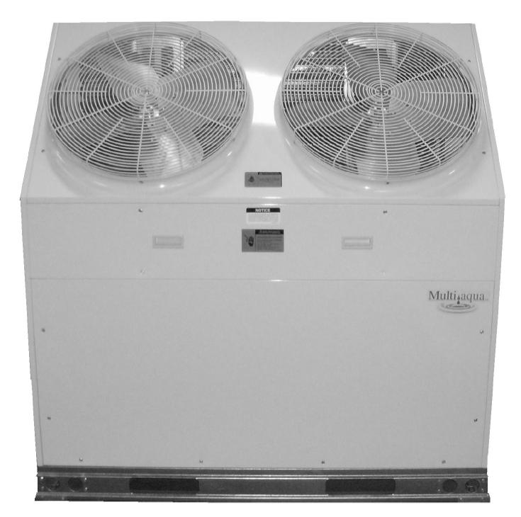
1 MAC120 Air-Cooled Chiller Air-Cooled Chillers for Global Residential and Light Commercial MicroClimates 9
2 MAC120 NOMENCLATURE BREAKDOWN MAC120 - XX - X - R Ton Air-Cooled Chiller Accessory Options N= No Options L= Low Ambient Kit Voltage 01 = 208/ /60 02 = 208/ /60 03 = 380/ /60 Available Model Numbers MAC N-R407 MAC L-R407 MAC N-R407 MAC L-R407 MAC N-R407 MAC L-R407 10
3 HVAC Guide Specifications Air-Cooled Liquid Chiller Nominal Size: 10 Tons Multiaqua Model Number: MAC N-407, MAC L-407 MAC N-407, MAC L-407 MAC N-407, MAC L-407 Part 1-General 1.01 System Description Multiaqua air-cooled liquid chillers are designed using scroll compressors and low sound condenser fans Quality Assurance A. Certified in accordance with U.L. Standard 95, latest version (U.S.A.) B. Construction shall comply with ASHRAE 15 Safety Code, NEC and ASME applicable codes. (U.S.A. Codes) C. Manufactured in a facility registered to ISO 9002, Manufacturing Quality Standard. D. ETL certified. E. Fully load tested at the factory. F. Damage resistant packaging Delivery, Storage and Handling A. Packaged and readied for shipment from the factory. B. Controls shall be capable of withstanding 150 F storage temperatures in the control compartment. C. Stored and handled per manufacturer s recommendations. Part 2-Product 2.01 Equipment A. General: 1. Unit shall be a factory assembled and tested air-cooled liquid chiller. 2. Shall be assembled on heavy gauge steel mounting/lifting rails. 3. Contained within the unit cabinet shall be all factory wiring, piping, controls, refrigerant charge (R407c), POE oil and special accessories required prior to start up. 4. Brass body strainer with 20 mesh screen and blow down shall be supplied in cabinet as a field installable accessory. B. Unit Cabinet: 1. Composed of heavy gauge galvanized steel casing with a baked polyester powder. 2. Capable of withstanding 500-hour salt spray test in accordance with the ASTM (U.S.A.) standard. C. Condenser Fans: 1. 4-blade, aluminum construction and shall be dynamically balanced and corrosion resistant. 2. Discharge air at a 45 vertical angle. 3. Motors and blades shall be protected by coated steel wire safety guards. D. Fan Motors: 1. Condenser fan motors shall be single speed, direct drive. 2. Totally enclosed. 3. Permanently lubricated sleeve bearings and Class F insulation. 4. Internal overload protection. E. Compressors: 1. Unit shall contain two fully hermetic scroll compressors. 2. Direct-drive, 3500 rpm (60Hz) 3. Compressor motor shall be suction gas cooled. 4. Internal motor protection. 5. Externally protected by low and high pressure cutout devices. 6. Individual vibration isolators. 11
4 F. Pump: 1. Unit shall be capable of incorporating a field installed chilled liquid solution pump. (Space restricted) 2. Unit shall have provisions to allow for chilled liquid solution piping to the exterior of the cabinet. G. Evaporator: 1. Evaporator shall have two independent refrigerant circuits. 2. Rated for a refrigerant side working pressure of 450 psig and a maximum water side working pressure of 60 psig. 3. Single pass, ANSI type 316 stainless steel, brazed plate construction. 4. Externally insulated with closed cell, elastomeric foam. (ASTM518) H. Condenser: 1. Condenser coil shall be air-cooled with integral subcooler. 2. Two independent refrigerant circuits. 3. Constructed of rifled copper tubing mechanically bonded to aluminum fins. 4. Cleaned and dehydrated. 5. Factory leak tested to 450 psig. I. Refrigerant Circuits: 1. Each circuit shall contain a sight glass, liquid line filter, thermal expansion valve, refrigerant charge of R407c and POE compressor oil. Part 3-Controls and Safeties 3.01 Controls A. Chiller shall be completely factory wired and tested. B. Capacity control shall be based on leaving chilled liquid solution temperature. 1. Temperature accuracy shall be F. 2. Controls shall be capable of staging the two compressors. C. Controls shall include the following components vac transformer to serve all controllers relays and control components. 2. Microprocessor based liquid solution temperature controller. 3. Leaving water temperature thermistor. 4. Pump bypass timer. 5. Compressor recycle timer. 6. Optional fan cycling control for low ambient operation. 7. Chilled liquid solution flow switch Safeties A. Unit shall be equipped with thermistors and all necessary components in conjunction with the control system to provide the following protectants. 1. Low refrigerant pressure. 2. High refrigerant pressure. 3. Low chilled liquid solution temperature. 4. Low chilled liquid solution flow. 5. Thermal overload. 6. Short cycling. Part 4-Operating Characteristics: 4.01 Temperatures A. Unit shall be capable of starting and running at outdoor temperatures from 55 F to 120 F. B. Optional Low Ambient Kit shall allow starting and running at outdoor temperatures to -20 F. A field supplied and installed crank case heater must be used when operating at these temperatures. C. Unit shall be capable of starting up with a maximum 80 F and a sustained 70 F entering fluid solution temperature to the evaporator. D. Minimum 10% Glycol solution is required. For outdoor temperatures below 32 F, reference MAC Glycol Solution Data table Electrical Requirements A. Primary electrical power supply shall enter the unit at a single location. B. Electrical power supply shall be rated to withstand 120 F operating ambient temperature. C. Units shall be available in 1 or 3-phase power at the voltages shown in the equipment electrical data. D. Control points shall be accessed through terminal block. 12
5 Model Number Model Number MAC120 Product Specifications Physical Data Condenser Coil Chiller Weight (lbs) Copper Tubing Diameter Height Length Coil Height Length Width Refrigerant (in) (in) Rows (in) (in) (in) R407c Net Shipping (in) MAC / oz x MAC / oz x MAC / oz x Electrical Data Volts/ Phase/ Hertz Compressor (Qty 2) 13 Condenser Fan Motor (Qty 2) (RLA) (LRA) (RLA) (RPM) Fuse or HACR Circuit Breaker Minimum Amps MAC / / x x x x 2 See note 1 MAC / / x x x See note 2 MAC /415/ /60 10 x 2 75 x x See note 2 Note: 1. MAC has two independent line voltage terminations. 2. MAC & MAC has one independent line voltage termination. Supply Wire Length in Feet Copper Wire Size (1% Voltage Drop) Supply Circuit Ampacity Compressor Copeland Scroll Refrigerant R407c Heat Exchanger Brazed Plate Max Flow Rate 28.8 gpm Min Flow Rate 18 gpm Supply Water Temp 44 Return Water Temp 54 Minimum System Solution Content 50 Gallons Expansion Tank Size 3% of Total System Water Connections 1 3/8" OD Supply & Return Internal Pressure Drop 18 ft of head Maximum Amps 75 x 2 See note 1 65 See note 2 35 See note 2 Multiaqua chillers are designed to operate exclusively with R407c refrigerant in a self-contained, pre-charged refrigerant system. Do not access the closed refrigerant circuit for any reason other than after-sale, after installation component replacement. Routine maintenance and service is to be performed by qualified personnel only. These specifications are subject to change without notice.
6 MAC120 Product Specifications MAC120 Capacity / Watts / EER* Outdoor Air F TONS KILOWATTS EER * Refrigerant system performance only, pump data not included. MAC120 Glycol Solution Data Propylene Glycol % Water Flow Capacity Min. Ambient Temp GPM Adjustment= 100% Capacity 10% x x F x % x x F x % x x F x % x x F x % x x F x 1.16 Example: 30% glycol solution. Maximum Flow Rate = 12gpm x System capacity x.98 *Use Propylene Glycol Only Important If the outside temperature is expected to fall below freezing (32 F) in the area the Multiaqua chiller is to be installed; the installer must take the following precautions. Failure to do so will void the warranty. To not engage in cold ambient mitigation will result in the failure of components such as the heat exchanger, piping, circulating pump, etc and or property damage. Keep the liquid solution at a minimum of 10% percent Propylene Glycol even in areas where there is no danger of freezing. The percentage amount of glycol recommended is dependent on the expected ambient temperatures and the solution makeup recommendation of the glycol manufacturer. Refer to the MAC120 Glycol Solution Data table above. Ensure the system circulating pump is in a constant energized mode to keep a continuous circulation of liquid solution. The Multiaqua chiller is a self-contained air-cooled condenser, coupled with an insulated brazed plate heat exchanger (evaporator). The system utilizes a scroll compressor to circulate refrigerant between the condenser and heat exchanger. The refrigerant is metered into the heat exchanger with a thermal expansion valve. Protecting the system are high and low pressure switches as well as a pump flow switch. Liquid solution (water and Propylene Glycol; minimum 10 % is required) is circulated through the heat exchanger by an externally mounted pump. The liquid solution flows through the heat exchanger to the system supply piping and on to the air handlers. Low ambient kits are available for operating ambient temperatures down to -20 degrees Fahrenheit. A field supplied and installed crankcase heater must be installed when operating at these temperatures. The low ambient kits consist of an ICM 325 (+) ICM (175) for single and three phase 208/230 vac chillers. For the three phase 380/460 vac chillers a pressure activated fan control is used. These specifications are subject to change without notice. 14
7 MAC120 Cooling Performance Data LWT ( F) MAC120 CAPACITIES with 0% Glycol ENTERING AIR TEMPERATURE ( F) TONS GPM TONS GPM TONS GPM TONS GPM TONS GPM MAC120 CAPACITIES with 10% Glycol LWT ( F) ENTERING AIR TEMPERATURE ( F) TONS GPM TONS GPM TONS GPM TONS GPM TONS GPM MAC120 CAPACITIES with 20% Glycol LWT ( F) ENTERING AIR TEMPERATURE ( F) TONS GPM TONS GPM TONS GPM TONS GPM TONS GPM These specifications are subject to change without notice. 15
8 MAC120 Cooling Performance Data MAC120 CAPACITIES with 30% Glycol LWT ( F) ENTERING AIR TEMPERATURE ( F) TONS GPM TONS GPM TONS GPM TONS GPM TONS GPM MAC120 CAPACITIES with 40% Glycol LWT ( F) ENTERING AIR TEMPERATURE ( F) TONS GPM TONS GPM TONS GPM TONS GPM TONS GPM MAC120 CAPACITIES with 50% Glycol LWT ( F) ENTERING AIR TEMPERATURE ( F) TONS GPM TONS GPM TONS GPM TONS GPM TONS GPM These specifications are subject to change without notice. 16


9 17
10 Table of Contents Page Introduction 19 System Description & Sequence of Operation 20 Electrical & Physical Data 21 Description of Electrical Controls 23 Chiller Controls Sequence of Operation 25 Refrigeration System Operation 26 Description of Refrigeration Components 26 Piping System Components 28 Layout & Design 29 Banked Chiller Configuration 30 Installation Notes 31 Propylene Glycol Content 32 Expansion Tank 32 Filling the System with Propylene Glycol 33 Air Elimination 33 18
11 Multiaqua Chiller Manual The Multiaqua Chiller System is the only air conditioning/refrigeration system of its kind in the world today offering the degree application flexibility described in the following manual. The Multiaqua Chiller System is not only unique in its application flexibility; it is unique in superior quality, rated capacities and rugged durability. When installed in accordance with these instructions the system will deliver years of trouble free service. Proper equipment sizing, piping design and installation are critical to the performance of the chiller. This manual is meant to be a how to introduction to piping and installing the Multiaqua Chiller System. MAC120 Chiller Features Copeland Scroll Compressors Advanced Motor Protection Loss of Flow Protection Control Power Transformer Low Ambient Option Integrated Chilled Solution Pump Control Flow Switch Strainer Connection Kit Painted Metal Condenser Protector Grille Dual Refrigeration Circuits and Single Liquid Solution Circuit RECOGNIZE THIS SYMBOL AS AN INDICATION OF IMPORTANT SAFETY OR INSTRUCTION RELATED INFORMATION. Web site information addresses are supplied throughout this manual for piping and accessory information. The plumbing industry also has pressure drop information on ferrous and copper piping systems. The following sections will describe each component and how it functions within the system. Installation information is supplied where appropriate. The piping design section will explain the design and layout the piping system from a how to perspective. Following the examples provided will enable the installer to determine the correct pipe and accessory sizing, as well as equipment location. It is important to know before installation if the proposed system will operate correctly and by doing a formal layout of a new application or review of an existing piping system will make that determination. Throughout this manual the term liquid solution is used in place of water. The chiller circulates a solution of water and Propylene Glycol. It is essential to operate the system with a minimum of 10% glycol. DO NOT OPERATE THIS SYSTEM USING WATER ALONE. For proper liquid solutions mix ratios, refer to page 14 or the glycol manufacture s recommended mix ratios. 19


 by various sections of a structure at a given time.")

12 System Description & Sequence of Operation The Multiaqua Chiller is a self-contained, air-cooled condenser, coupled with an insulated brazed plate heat exchanger (evaporator). The system utilizes scroll compressors to circulate refrigerant between the condenser and heat exchanger. The refrigerant is metered into the heat exchanger with a thermostatic expansion valve. Protecting the system are high and low pressure switches as well as a pump flow switch. Liquid solution (water and Propylene Glycol is circulated through the heat exchanger by a field supplied pump. The liquid solution flows through the heat exchanger to the system supply piping and on to the air handlers. A solenoid-operated, motorized valve or circulator controls the flow of the chilled liquid solution through the air handlers. The valves or circulators can be actuated by a variety of different control schemes. Liquid solution temperature is controlled by a chiller mounted digital electronic controls. A system sequence of operation, individual control description, troubleshooting information and a schematic are included in the controls section. It must be recognized that ferrous pipe may cause acceleration deterioration of the brazed plate heat exchanger and could void the heat exchanger warranty. Cooling load Diversity Equipment sizing for a chilled liquid solution system can utilize Cooling Load Diversity. Diversity is described as the actual amount of cooling needed (heat load) by various sections of a structure at a given time. Conventional air conditioning systems are designed for the highest structure heat load. The conventional system determines and selects equipment based on the peak heat load demanded by the structure. A system sized to take advantage of diversity would determine the heat load by the time of day, building exposure and usage. As an example the sections of a structure facing west, demand more cooling in the afternoon, than sections facing east. The opposite of this is true in the morning, where the east section is exposed to a higher heat load requiring more cooling. Utilizing diversity the chiller system would adapt to the needs of each side of the structure during peak demand by delivering more cooling to that area and less to the areas that do not need it. A structure utilizing a conventional DX system, requires 8 tons of cooling at peak load, could utilize a much smaller capacity system (potentially 4 or 5 tons) if the system installed could take advantage of load diversity, which would supply the necessary amount of cooling to the space, as and when needed instead of keeping a larger capacity available at all times. Cooling load diversity can best be determined by referring to ACCA. (Air Conditioning Contractors of America) Manual J, Refer to the appendix A-2, Multi-Zone Systems. ACCA s Internet address is Because of diversity a Multiaqua Chiller can serve more total air handler tonnage than chiller capacity. A 10-ton chiller may be delivering chilled liquid solution to 15 or more tons of air handler capacity. Because of cooling load diversity, the building does not need equal amounts of cooling in each area at the same time. 20
13 ELECTRICAL AND PHYSICAL DATA The information contained in this manual has been prepared to assist in the proper installation, operation and maintenance of the chiller. Improper installation, or installation not made in accordance with these instructions can result in unsatisfactory operation and/or dangerous conditions and can cause the related warranty not to apply. Read this manual and any instructions packaged with separate equipment required to make up the system prior to installation. Retain this manual for future reference. Separate and independent power supplies and disconnects must be provided. These chillers have separate and discreet power requirements within one cabinet. All power to the chiller must be turned off prior to opening cabinet and or servicing. Failure to properly ground chiller can result in death. Disconnect all power wiring to chiller before maintenance or service work. Failure to do so can cause electrical shock resulting in personal injury or death. All wiring must be done in accordance with the NEC (National Electric Code) as well as state and local codes, by qualified electricians. Product warranty does not cover any damages or defect to the chiller caused by the attachment or use of any components, accessories or devices (other than those authorized by the manufacturer) into, onto or in conjunction with the chiller. You should be aware that the use of unauthorized components, accessories or devices may adversely affect the operation of the chiller and may also endanger life and property. The manufacturer disclaims any responsibility for such loss or injury resulting from the use of such unauthorized components, accessories or devices. Upon receiving the chiller and components, inspect for any shipping damage. Claims for damage, either apparent or concealed should be filed immediately with the shipping company. No liquid other than the solution of water and Propylene Glycol (mixed in accordance with table 6 page 32) shall be used in the piping system. Corrosive environments may subject metal parts of the chiller to rust and deteriorate. The oxidation could shorten the chiller s useful life. Corrosive elements include salt spray, fog or mist in sea coastal areas, sulfur or chlorine from lawn watering systems and various chemical contaminants from industries such as paper mills and petroleum refineries. If the unit is to be installed in an area where contaminates are likely to be a problem, special attention should be given to the equipment location and exposure. Avoid having lawn sprinklers spray directly on the chiller cabinet. In coastal areas, locate the chiller on the side of the building away from the water front. Elevating the chiller off of its slab or base enough to allow air circulation will help avoid holding water in contact with the cabinet base. Regular maintenance will reduce the build-up of contaminants and help protect the cabinet finish. In severe locations having the chiller coated with an epoxy or other coating formulated for air conditioning systems located in coastal areas may be necessary. 21


14 Consult local building codes or ordinances for special installation requirements. When selecting a site to locate the chiller, consider the following: A minimum clearance of 60 on the service access front, 12 on the rear air inlet and a 60 fan discharge clearance. The chiller can be located out or indoors. If installed indoors there must be 9000 cfm of outdoor air changes circulated through the mechanical room to sufficiently operate the chiller. No ductwork can be connected to the chiller s condenser or condenser fans. If a concrete slab is used, do not connect the slab directly to any building s foundation or structure to prevent sound transmission. Locate the slab on a level surface that is above grade to prevent ground water from entering the chiller cabinet. 60 Fan Discharge Clearance Stated Service Clearances 12 Rear Clearance 60 Front Service Clearance 0 Side Clearance Chiller Supply and Return Piping Access
, energizing the pump relay, allowing the pump to operate long enough to close the flow")


15 Description of Electrical Controls Control Transformer: The control transformer is rated at 24 vac, 40 va (1.6 24vac) Pump Bypass Timer: The pump bypass timer is a 24 vac, 3-wire control. When energized the timer will bypass the flow switch for 10 seconds (by creating a circuit to the pump relay), energizing the pump relay, allowing the pump to operate long enough to close the flow switch. In a normally operating system the flow switch will stay closed powering the pump relay in series with the low and high- pressure switches. Should the flow switch open, the timer can only be reset by opening and closing the chiller's line voltage disconnect. Refrigerant System Timer: The refrigerant timer is a 24 vac, 5-minute delay on break, 20wire timer. The normally closed contacts of the timer energize the compressor contactor through the chilled solution control. When the chilled solution control contacts open, the timer delays by opening its contact for 5- minutes before resetting to the closed position. High Pressure Switch: The high-pressure switch is an automatic reset control that senses compressor discharge line pressure. It opens at 400 PSIG and closes at 300 PSIG. 23


16 Description of Electrical Controls (continued) Low Pressure Switch: The low-pressure switch is an automatic reset control that senses compressor suction line pressure. It opens at 40 PSIG and closes at 80 PSIG. Flow Switch: The flow switch senses liquid solution flow. The paddle of the switch is inserted through a fitting into the pump discharge line. Liquid solution flow deflects the paddle closing the switch. The flow switch is position sensitive. The arrow on the switch must point in the direction of liquid solution flow. Compressor Contactor: The compressor contactor energizes the compressor through the two or three normally open contacts. The contactor coil operates (closes the contacts) when energized by 24 vac. Liquid Solution Temperature Control: The liquid solution temperature control is an adjustable microprocessor based temperature control. This control receives temperature information from a thermistor located on the liquid solution supply line. A liquid crystal display continually indicates liquid solution temperature. The control is mounted inside the chiller cabinet. 24
17 Chiller Controls Sequence of Operation When powered up, the Multiaqua chiller system energizes the control transformer creating 24 vac control voltage. First the pump bypass timer is energized and temporarily bypasses the flow switch, energizing the pump relay. The pump then starts to move liquid solution through the piping system (in a properly filled and air purged system). The movement of liquid solution from the pump discharge keeps the flow switch closed. After a 10 second delay the pump contact opens, connecting the flow switch in series with the high and low pressure switches. The pump will now run continually unless the power supply is interrupted, or the flow switch opens. If the liquid solution temperature controller is calling for cooling the control circuit is routed through the short cycle timer and the three safety switches (the flow, high and low pressure switches) to the compressor contactor. This will energize the compressor(s) and condenser fan motors. The liquid solution controller will open at the user programmed set point, causing the refrigerant short cycle timer to open it's contact for 5 minutes as it delays before resetting to the closed position. This will de-energize the compressor. Power fluctuations will also initiate a 5 minute time delay. The 5 minute delay allows the refrigerant system a period for pressure equalization, protecting the compressor(s) from short cycling. The chiller temperature controller utilizes a thermistor to monitor the liquid solution temperature change. The temperature is then compared to the set point and differential temperatures programmed into the control by the user. The set point is the liquid solution temperature which will cause the control switch to open. For example: The control set point is programmed at 44 F LWT with a 10 F differential, which opens the controller at 44 F LWT and closes at 54 F. The differential temperature is the number of degrees above set point temperature programmed into the controller. If liquid solution temperature falls to the set point, the controller cycles the compressors off. Chillers are shipped with the control set point adjusted to 44 F LWT and a 10 F differential. Liquid solution temperature set point should not be set below 35 F. 25


18 SYSTEM FAULTS: Flow Switch Opening: The flow switch is normally closed during pump operation. Should liquid solution flow be interrupted for any reason, the control will open shutting down and locking out the chiller operation. The only exception to this is when power is first applied to the chiller and the pump bypass timer bypasses the flow switch for 10 seconds. When the system is first filled with liquid solution and the pump is started, expect the system to cycle off on the flow switch until all of the air is removed from the piping system. The system will have to be reset by opening and then closing the disconnect switch or circuit breaker powering the chiller. Low Pressure Switch Opening: Should the compressor suction pressure go low enough (40 PSI) to open the lowpressure switch, the compressor and condenser fan motors will shut down. Check for a refrigerant leak, inoperative thermal expansion valve, low liquid solution control setting, low ambient operation, low liquid solution flow, etc. High Pressure Switch Opening: Should the compressor discharge pressure go high enough to open the high- pressure switch the compressor and condenser fan motors will shut down. Check for a dirty condenser coil, inoperable fan motor(s) or the recirculation of condenser air. Refrigeration System Operation The refrigeration system is a closed loop consisting of 2 compressors, dual circuit heat exchanger (evaporator), metering devices (TXVs) and condenser coil. The refrigerant circulated is R407c. Hot gas is pumped from the compressors to the to the condenser coil where the two condenser fans pull cooler air across the coil condensing and sub cooling the refrigerant. The now liquid refrigerant flows through the liquid line to the thermal expansion valves, where the refrigerant pressure drops causing the refrigerant to boil at a much lower temperature (34-40 F). The refrigerant leaves the expansion valves and swirls through the plates of the heat exchanger absorbing heat from the circulating liquid solution. The evaporator or heat exchanger is designed to operate with an 8-10 F superheat. The condenser is designed to condense the refrigerant and sub cool it to 10 F below condensing temperature. Description Of Refrigerant Components Scroll Compressor: All Multiaqua chillers feature Scroll compressors. Scroll technology ensures reliable high performance at a low sound level over a wide range of operating conditions. Caution the top half of the scroll compressor operates at a temperature high enough to cause serious injury. 26


19 Description Of Refrigerant Components (continued) Brazed Plate Heat Exchanger: The "Heat Exchanger" or evaporator is of a brazed copper and stainless steel design. Refrigerant and liquid solution is channeled through narrow openings between plates and flows in opposite directions. The counter flow design and fluid turbulence ensures maximum heat exchange at minimal pressure drop. Thermal Expansion Valve: Multiaqua chillers are equipped with Thermal Expansion valves. The valves feature a liquid charged sensing bulb for consistent superheat at various load conditions. Condenser Coil: The air-cooled condenser coil is of copper tube with aluminum fin construction. The coil is protected by a painted metal condenser grille. 27


20 Piping System Components Supply Storage Tank: The supply storage tank must be used in the system with less than 25 gallons of liquid solution. The tank prevents rapid cycling of the compressors and acts as a reserve for chilled liquid solution. Supply storage tank must be insulated in the field. Part Number: WX202H (20 Gallon) WX202H (42 Gallon) Expansion Tank and Air Scoop: The Expansion Tank and Air Scoop assembly is used to compensate for the expansion and contraction of liquid in the system. The air scoop eliminates air entrance in the liquid solution. Part Number: 1500/1" Liquid Solution Bypass Valve: The liquid solution bypass valve relieves system pressure from the liquid solution supply to the return as system air handler control are cycled off. Part Number: D146M1032-3/4" D146M /4" Motorized Valve: The air handler motorized valve controls the flow of liquid solution to the systems air handlers. Each air handler in the system should have a motorized or solenoid valve. Part Number: MZV524E-T 1/2" 2-Way Zone Valve MZV525E-T 3/4" 2-Way Zone Valve MZV526E-T 1" 2-Way Zone Valve VT3212G13A020 1/2" 3-Way Zone Valve VT3212G13A020 3/4" 3-Way Zone Valve 28
21 Composite Piping Layout and Design Understanding the function and friction loss of each part of the piping system is important to the layout and successful installation of a chilled liquid solution system Way Liquid Solution Control Valves Bypass Valve Storage Tank Expansion Tank Coil Chiller Pump The circulation pump is the key performer in the piping system. The pump must circulate the liquid solution through the heat exchanger and piping system to the air handlers. Pumps are designed to deliver a flow rate measured in gallons per minute(gpm). The pump must be able to overcome the resistance to flow (pressure drop) imposed by the chiller components, piping system and air handlers while maintain the necessary flow rates in gallons per minute. Pump capacities in gallons per minute and pressure drop (feet of head) are listed in table 1. An adjustable valve must be used to throttle the discharge liquid solution flow rate to appropriate levels based on capacity and glycol mix percentages. Table 1 Chiller System Data MAC Series Min. Liquid Solution Flow Rate Max.Liquid Flow Rate Min. Liquid Solution Content in System Expansion Tank Size Internal Chiller Pressure Loss Chiller Liquid Solution Content GPM GPM Gallons Gallons Ft.of Head Gallons MAC % of Total Piping resistance or pressure drop is measured in feet of head. A foot of head is the amount of pressure drop imposed in lifting liquid solution one foot. Pumps in the Multiaqua system are designed to move rated liquid solution flow (see table 1) in GPMs. 29
22 Banked Chiller Configuration Notes: Installing Multiaqua chillers in parallel is recommended. 30
23 Installation Notes: Piping such as PEX,steel, copper or PVC can be used with the Multiaqua system. Check local building codes for material conformation. Care must be taken when using PVC as the presence of propylene glycol may destroy plastics. Pressure drop data for the selected piping material is readily available and should be used. Should the Multiaqua chiller be installed using existing steel (ferrous metal) piping system, dielectric fittings must be used at the chiller and air handler. The factory supplied wye strainer will capture particles of rust and sediment inherent with steel piping and should be checked and cleaned after initial start up and open a regular maintenance during the life of the system. Any piping used to conduct liquid solution must be insulated in accordance with local and national mechanical codes. Information on insulation installation and application can be obtained from Armaflex web site at and Owens-Corning site at For future servicing of the chiller and air handlers, it is suggested that shutoff valves be installed at the chiller and air handler(s). If ball valves are used, they can double as balancing valve(s) in the supply piping at each air handler. Chiller shutoff valves should be attached at the chiller connections with unions. The air handlers are to be controlled with electrically operated "slow-opening" solenoid valves, circulators or motorized zone valves as manufactured by Erie controls ( A remote thermostat or air handler installed digital control operate the valves. Bypass valves as shown in drawing 1, should be installed between the supply and the return chilled liquid solution supply pipes at a convenient location to the installation. The bypass valve operates to bypass liquid solution between the supply and return chilled liquid solution lines. In the event air handlers valves should shut down, the bypass valve is set to open up and bypass liquid solution between the supply and return lines, relieving pressure and eliminating the possibility of pump cavitations. To adjust the valve, run the system with one air handler solenoid actuated. De-energize the solenoid valve, (at this point no liquid solution will be flowing through the air handlers.) and adjust the bypass valve to relieve pressure between the supply and return piping. Bleed ports will be factory installed on all Multiaqua air handlers. Bleed ports are opened to eliminate air trapped in the air handlers after filling the system with liquid solution and Propylene Glycol and before operating the refrigerant compressor in the chiller. The minimum liquid solution content in the chiller system,(piping, chiller, and air handlers), is 50 U.S. gallons. Estimate the system liquid solution content. Should the system have less than 50 gallons of liquid solution content, a chilled liquid solution storage tank must be installed. The tank stores enough chilled liquid solution to prevent frequent chiller compressor cycles at light load and prevents chilled liquid temperature swings at higher load conditions when the chiller compressor is waiting to cycle on the time delay control. Propylene Glycol must be added to the water used in the system. Propylene helps prevent freeze-ups due to low ambient temperature conditions and low chilled liquid solution temperatures. In comparison to water, Propylene Glycol slightly lessons the temperature exchange in the chiller heat exchanger. However, that is offset by the increased flow of liquid solution through the piping system enabled by the Propylene Glycol. To determine the Propylene Glycol content for various ambient temperatures refer to table 6 page 32. In no instance should a Multiaqua chiller be installed with less than 10% Propylene Glycol content in the piping system. Using less than the recommended Propylene Glycol percentage content voids equipment warranty. 31
24 Polypropylene Glycol System Content vs. Minimum Ambient Temperature To not engage in cold ambient mitigation will result in the failure of components, property damage and void warranty. Table 6 Percent of Propylene Glycol to Water Content Propylene Water Min. Ambient Capacity Glycol % Flow Temperature 10% x x F 20% x x F 30% x x.98 8 F 40% x x.97-7 F 50% x x F GPM Adjustment = 100 % Capacity x 1.01 x 1.03 x 1.07 x 1.11 x 1.16 Ethylene Glycol is environmentally hazardous and not recommended. Inhibited Propylene Glycol ( typical automotive coolant) is not to be used in a Multiaqua Chiller under any circumstances. Dow Chemical's "Ambitrol" family of Glycol-based coolants of food grade Propylene Glycol is suggested. Information on Ambitrol is available from Dow at search word "Ambitrol". Expansion Tanks: Liquid solution expansion and contraction within the closed system must be compensated for with an expansion tank. The expansion tank used with the Multiaqua system, is a steel tank with a rubber bladder attached to it internally. There is air pressure on one side of the rubber bladder that keeps the bladder pushed against the sides of the tank before the system is filled with liquid solution (illustration above). As the liquid solution heats up the bladder will be pushed further away from the tank walls, allowing for expansion and contracting as the liquid solution temperature changes. By flexing, the bladder controls the system pressure adjusting to temperature variations of the chilled liquid solution system. It is critical that the expansion tank's air bladders pressure be less than the system solution pressure. Air pressure can be measured with an automotive tire gauge at the bicycle valve port on the expansion tank. Bleeding air out of the bladder or increasing the pressure with a bicycle pump will adjust pressure. System must use a liquid solution storage tank if system volume is less than 50 U.S. gallons. 32
25 Filling System with Liquid Solution and Coolant (Propylene Glycol) Before filling system with Propylene Glycol and water, pressure test the piping system with compressed air. Testing should be done at a maximum of 50 psi.the system should hold air pressure for a minimum of one hour with no leakage. Concentrations of Propylene Glycol in excess of 50% will destroy o-rings in fittings and pump. Water should be added to the system first or a liquid solution diluted Propylene Glycol mix. System that contains 50 or more U.S. gallons should have a tee fitting with a stopcock installed in the return line close to the chiller. The stopcock can be opened and attached to a hose with a female X female hose fitting. In the open end of the hose section (1-1.5 feet long) insert a funnel and pour into the system the diluted Propylene Glycol/liquid solution mixture or add water first and then the quantity of Propylene Glycol needed for minimum ambient protection (refer to Table 6). After adding the Propylene Glycol/water mixture, or liquid solution and then coolant proceed to add enough water to the system to achieve a 15 psi gauge pressure. To measure system pressure shut off the stopcock, remove hose and attach a water pressure gauge. Open the stopcock to read system pressure. Systems that use the Chilled Liquid Solution Storage Tank should be filled at the tee/stopcock fitting in the outlet fitting of the storage tank. Fill the tanks with 10 gallons of water and with a funnel pour the calculated (refer to Table 6) amount of Propylene Glycol into the tank. The amount of Propylene Glycol added should be calculated to achieve minimum ambient protection. After adding Propylene Glycol, fill the system with enough liquid solution to bring system pressure to approximately 15 psi gauge pressure. To measure system pressure shut off the stopcock and attach a water pressure gauge. Open the stopcock to read system pressure. Air Elimination Since we have the system filled we must eliminate the air left in the system. Briefly open each bleed valve at the air handlers and allow trapped air to escape. This will eliminate much of the air left in the system. Next we will start the pump and continue bleeding air from the system. Be sure the chiller has line voltage available to it and set the chilled liquid solution control up to 100 F, which will ensure that only the pump runs at this point. The pump should now start and remain running. Should the pump stop at any time during this process it is an indication that the flow switch had air move across it allowing the circuit to be interrupted. Continue to bleed some air out of the system at the highest locations before resetting the pump bypass timer to get the pump running again. Open and close the power supply switch to the chiller to restart the pump. Continue bleeding air with the pump operating. You may have to start and re-start the pump a few times to complete air removal. If you continue having air entrapment issues, it will be necessary to install a micro bubble remover device. All piping systems should have a minimum of 10% Propylene Glycol in the system even in climates with nonfreezing ambient temperatures. Using less than the recommended Propylene Glycol percentage content voids equipment warranty. Liquid solution control valves (solenoid or motorized valves) should be selected for low pressure drop. If a selected valve contributes to pushing your total head calculation to more than 50 feet of head, a larger valve may be needed to bring your total head below the maximum of 50 feet. Liquid Solution Balancing: Liquid solution balancing will require an accurate digital thermometer to measure return line liquid solution temperature at each air handler. Set the chilled liquid solution temperature control in the chiller at a normal operational temperature (44 F) and measure pump discharge temperature with the digital thermometer to check system solution temperature. After the chilled liquid solution temperature has lowered to the set point begin the balancing process. The system must be free of air and each air handler set at a temperature low enough to continue cooling operation (and liquid solution flow) during the balancing process. Begin by measuring the return line chilled liquid solution temperature of each air handler. Begin incrementally closing the supply line balance valve at the air handlers with the lowest return line chilled liquid solution temperature. Continue this process until each air handler has close to the same return line chilled liquid solution temperature. 33
26 MAC120-3 Ladder Wiring Diagram 380/ /60 34
27 MAC120-3 Wiring Diagram 380/ /60 MULTIAQUA BL 380/ /60 L1 RD L2 CON1` RD WH T1 COMP T2 1 T3 380/460-3 TRANSFORMER 24 vac BL YL YL RD BL FS LPS1 BL GND L3 WH CON2 RD WH T1 T2 T3 COMP HPS1 TIMER1 WH REL 1 REL 2 2 TM2 1 NOTE BL LPS2 BL BL BL 3 4 BL BL DTC 1 NO C DTC 2 NO C BL HPS2 24 vac COM 24 vac WH WH COM FC1 FAN 1 FC2 FAN 2 2 TM2 1 RD WH TITLE AUTHOR MAC / /60 kjg LEGEND: FACTORY WIRING FIELD WIRING CON COMPRESSOR CONTACTOR FS FLOW SWITCH LPS LOW PRESSURE SWITCH NOTES: 1.PUMP STARTER RELAY DATE REVISION 09/22/ REV 1 DTC DIGITAL TEMPERATURE CONTROLLER FC CONDENSER FAN CONTACTOR REL CONDENSER FAN RELAY HPS TIMER TM2 HIGH PRESSURE SWITCH PUMP BYPASS TIMER REFRIGERANT SYSTEM TIMER 35
28 MAC120-3-L with Low Ambient Kit Wiring Diagram 380/460/-3-50/60 MULTIAQUA 380/ /60 L1 RD L2 CON1` RD WH BL T1 COMP T2 1 T3 380/460-3 TRANSFORMER 24 vac BL YL YL RD BL FS LPS1 BL GND L3 WH CON2 RD WH T1 T2 T3 COMP HPS1 TIMER1 NOTE 1 REL 1 REL 2 2 TM2 1 FAN CYCLE PRESSURE SWITCH 1 2 BL LPS2 BL 3 4 FAN CYCLE PRESSURE SWITCH BL BL DTC 1 NO C DTC 2 NO C 24 vac COM 24 vac COM FC1 NOTE 2 BL 1 FAN FC2 4 FAN HPS2 2 TM2 1 NOTE 3 TITLE AUTHOR DATE REVISION MAC WITH LOW AMBIENT KIT kjg 09/22/ REV 1 LEGEND: FACTORY WIRING FIELD WIRING DTC DIGITAL TEMPERATURE CONTROLLER FC CONDENSER FAN CONTACTOR REL CONDENSER FAN RELAY CON FS LPS HPS TIMER TM2 COMPRESSOR CONTACTOR FLOW SWITCH LOW PRESSURE SWITCH HIGH PRESSURE SWITCH PUMP BYPASS TIMER REFRIGERANT SYSTEM TIMER NOTES: 1. PUMP STARTER RELAY 2. LOW AMBIENT RELAY #1 3. LOW AMBIENT RELAY #2 36
29 MAC120-2 Ladder Wiring Diagram 208/ /60 37
30 MAC120-2 Wiring Diagram 208/ /60 38
31 MAC120-2-L with Low Ambient Kit Wiring Diagram 208/ /60 39
32 MAC120-1 Ladder Wiring Diagram 208/ /60 40
33 MAC120-1 Wiring Diagram 208/ /60 41
34 MAC120-1-L with Low Ambient Kit Wiring Diagram 208/ /60 42
35 MAC120 CERTIFIED DRAWING 43
Multiaqua Chiller Manual
 Rev. 1.1 Multiaqua Chiller Manual The Multiaqua Chiller System is the only air conditioning/refrigeration system of its kind in the world today offering the degree of application flexibility described
Table of Contents. Page 2 of 28
 Rev. 1.1 Table of Contents Page Introduction 3 System Description 4 Electrical & Physical Data 5-6 Description of Electrical Controls 7-8 Chiller Controls Sequence of Operation 9 System Faults 10 Refrigeration
MAC N-407 Air-Cooled Chiller
 MAC036-01-N-407 Air-Cooled Chiller Air-Cooled Chillers for Global Residential and Light Commercial MicroClimates MAC036 NOMENCLATURE BREAKDOWN MAC036-01 - N - 407 Refrigerant Type Air-Cooled Chiller 036=
MACH N-407 Heat Pump Air-Cooled Chiller
 MACH060-01-N-407 Heat Pump Air-Cooled Chiller Heat Pump Air-Cooled Chillers for Global Residential and Light Commercial Microclimates MACH NOMENCLATURE BREAKDOWN MACH-060-01 - N - 407 Refrigerant Type
MAC-120HE-03 Air-Cooled Chiller
 MAC-120HE-03 Air-Cooled Chiller 10 Ton / 120,000 BTUH Air-Cooled Chiller 380/415/460-3-50/60 1 HVAC Guide Specifications Air-Cooled Liquid Chiller Nominal Size: 10 Tons Multiaqua Model Number: MAC-120HE-03
MAC-036HE-02-L High Efficiency Air-Cooled Chiller Air-Cooled Chillers for Global Residential and Light Commercial Micro Climates Rev 1.
 MAC-036HE-02-L High Efficiency Air-Cooled Chiller Air-Cooled Chillers for Global Residential and Light Commercial Micro Climates Rev 1.1 HVAC Guide Specifications Air-Cooled Liquid Chiller with Low Ambient
MAC-048HE-01-L High Efficiency Air-Cooled Chiller Air-Cooled Chillers for Global Residential and Light Commercial Micro Climates Rev 1.
 MAC-048HE-01-L High Efficiency Air-Cooled Chiller Air-Cooled Chillers for Global Residential and Light Commercial Micro Climates Rev 1.1 HVAC Guide Specifications Air-Cooled Liquid Chiller with Low Ambient
MAC-060HE-01-L High Efficiency Air-Cooled Chiller Air-Cooled Chillers for Global Residential and Light Commercial Micro Climates Rev 1.
 MAC-060HE-01-L High Efficiency Air-Cooled Chiller Air-Cooled Chillers for Global Residential and Light Commercial Micro Climates Rev 1.2 HVAC Guide Specifications Air-Cooled Liquid Chiller with Low Ambient
Table of Contents (Hydronic)
") Table of Contents (Hydronic) About Us System Modeling Software Multi-Zoning and Energy Cost Features and Benefits Water Products Overview DX Products Overview Accessory Products Overview Equipment Sound
Table of Contents (Hydronic) About Us System Modeling Software Multi-Zoning and Energy Cost Features and Benefits Water Products Overview DX Products Overview Accessory Products Overview Equipment Sound
MAC Chiller Installation and Operation Manual
 MAC Chiller Installation and Operation Manual TABLE OF CONTENTS...PAGE Table of Contents...40 Multiaqua Chiller Manual Introduction...41 System Description & Sequence of Operation...42 Electrical & Physical
MZCool Chiller Installation and Operation Manual
 MZCool Chiller Installation and Operation Manual TABLE OF CONTENTS...PAGE Table of Contents...1 MZCool Chiller Manual Introduction...2 System Description & Sequence of Operation...3 Electrical & Physical
B. Unit construction shall comply with ASHRAE 15 Safety Code, NEC, and ASME applicable codes (U.S.A. codes).
.") Guide Specifications PART 1 GENERAL 1.01 SYSTEM DESCRIPTION Microprocessor controlled, air-cooled liquid chiller utilizing scroll compressors, low sound fans, hydronic pump system and optional fluid storage
Guide Specifications PART 1 GENERAL 1.01 SYSTEM DESCRIPTION Microprocessor controlled, air-cooled liquid chiller utilizing scroll compressors, low sound fans, hydronic pump system and optional fluid storage
MHNCCX DX with Hot Water Heat Ceiling Concealed 4-Pipe Heat / Cool Fan Coil 12,000-36,000 BTUH
 MHNCCX DX with Hot Water Heat Ceiling Concealed 4-Pipe Heat / Cool Fan Coil 12,000-36,000 BTUH 318 MHNCCX NOMENCLATURE BREAKDOWN 4-Pipe Heat/Cool Ceiling Concealed Fan Coil MHNCCW- XX - XX Ceiling Concealed
TECHNICAL GUIDE DESCRIPTION SPLIT-SYSTEM AIR-COOLED CONDENSING UNITS MODELS: HF-07 FEATURES B-0703
 TECHNICAL GUIDE SPLIT-SYSTEM AIR-COOLED CONDENSING UNITS MODELS: HF-07 DESCRIPTION These Sunline 2000 units are completely assembled, piped and wired at the factory to provide one-piece shipment and rigging.
CWA4 Chilled & Hot Water Fan Coil
 CWA4 Chilled & Hot Water Fan Coil 4-Pipe Heat & Cool Fan Coil 24,000-60,000 BTUH 259 CWA4 NOMENCLATURE BREAKDOWN 4-Pipe Heat & Cool Multiposition Fan Coil Nominal BTUH 24=24,000 36=36,000 48=48,000 60=60,000
MHNCCW (4-Pipe) Chilled/Hot Water Ceiling Concealed 208/230V 4-Pipe Heating & Cooling Fan Coil 12,000 BTUH
 Chilled/Hot Water Ceiling Concealed 208/230V 4-Pipe Heating & Cooling Fan Coil 12,000 BTUH") MHNCCW-04-01 (4-Pipe) Chilled/Hot Water Ceiling Concealed 208/230V 4-Pipe Heating & Cooling Fan Coil 12,000 BTUH Rev. 1.2 HVAC Guide Specifications Chilled and Hot Water Fan Coil 4-Pipe Nominal Size: 12,000
MHNCCW-04-01 (4-Pipe) Chilled/Hot Water Ceiling Concealed 208/230V 4-Pipe Heating & Cooling Fan Coil 12,000 BTUH Rev. 1.2 HVAC Guide Specifications Chilled and Hot Water Fan Coil 4-Pipe Nominal Size: 12,000
TECHNICAL GUIDE. Description SPLIT-SYSTEM AIR-COOLED CONDENSING UNITS YD360, 480 & THRU 50 NOMINAL TONS YTG-B-0811
 Description These units are completely assembled, piped and wired at the factory to provide one-piece shipment and rigging. Each unit is pressurized with a holding charge of Refrigerant R-410A for storage
MHCCW Chilled Water Ceiling Concealed With 5kW Electric Heat 2-Pipe Heat / Cool Fan Coil 30,000 BTUH
 MHCCW-10-05 Chilled Water Ceiling Concealed With 5kW Electric Heat 2-Pipe Heat / Cool Fan Coil 30,000 BTUH Rev. 1.21 HVAC Guide Specifications Chilled Water Fan Coil with Electric Heat 2-Pipe Nominal Size:
MHCCW Chilled Water Ceiling Concealed Without Electric Heat 2-Pipe Heat / Cool Fan Coil 18,000 BTUH
 MHCCW-06-00 Chilled Water Ceiling Concealed Without Electric Heat 2-Pipe Heat / Cool Fan Coil 18,000 BTUH Rev. 1.21 HVAC Guide Specifications Chilled or Hot Water Fan Coil 2-Pipe Nominal Size: 18,000 BTUH
CWA2 Chilled Water Fan Coil With or Without Electric Heat 2-Pipe Heat / Cool Fan Coil 18,000-60,000 BTUH
 CWA2 Chilled Water Fan Coil With or Without Electric Heat 2-Pipe Heat / Cool Fan Coil 18,000-60,000 BTUH 233 CWA2 NOMENCLATURE BREAKDOWN 2-Pipe Heat/Cool with Electric Heat Multiposition Fan Coil Nominal
Commercial High-Efficiency Condensing Units
 FORM NO. A22-194 REV. 2 Supersedes Form No. A22-194 Rev. 1 Commercial High-Efficiency Condensing Units RAWL High Efficiency 6.5 & 7.5 TON MODEL [22.86 & 26.38 kw] TABLE OF CONTENTS Model Number Designation...2
PACKAGE AIR CONDITIONER
 PACKAGE AIR CONDITIONER FORM NO. ATZ-206 TZAA- HIGH EFFICIENCY SERIES NOMINAL SIZE 10 TON [35.2 kw] 10 TON MODEL [35.2 kw] This product is shipped with a nitrogen holding charge that must be vented prior
PDF Created with deskpdf PDF Writer - Trial ::
 Instruction Manual Index Introduction Uncrating and Checking for Damage Locating Your Unit Installation Fill Tank Process Connections Pre Startup Startup Sequence Trouble Shooting Chart Operating Lights
CFFWA4P-12-1-U Chilled/Hot Water Universal Mount Fan Coil (4-Pipe) 4-Pipe Heat / Cool Fan Coil 36,000 BTUH
 4-Pipe Heat / Cool Fan Coil 36,000 BTUH") CFFWA4P-12-1-U Chilled/Hot Water Universal Mount Fan Coil (4-Pipe) 4-Pipe Heat / Cool Fan Coil 36,000 BTUH Rev. 1.3 HVAC Guide Specifications Chilled and Hot Water Universal Mount Fan Coil 4-Pipe Nominal
CFFWA4P-12-1-U Chilled/Hot Water Universal Mount Fan Coil (4-Pipe) 4-Pipe Heat / Cool Fan Coil 36,000 BTUH Rev. 1.3 HVAC Guide Specifications Chilled and Hot Water Universal Mount Fan Coil 4-Pipe Nominal
CFFWA4P-16-1-U Chilled/Hot Water Universal Mount Fan Coil (4-Pipe) 4-Pipe Heat / Cool Fan Coil 48,000 BTUH
 4-Pipe Heat / Cool Fan Coil 48,000 BTUH") CFFWA4P-16-1-U Chilled/Hot Water Universal Mount Fan Coil (4-Pipe) 4-Pipe Heat / Cool Fan Coil 48,000 BTUH Rev. 1.3 HVAC Guide Specifications Chilled and Hot Water Universal Mount Fan Coil 4-Pipe Nominal
CFFWA4P-16-1-U Chilled/Hot Water Universal Mount Fan Coil (4-Pipe) 4-Pipe Heat / Cool Fan Coil 48,000 BTUH Rev. 1.3 HVAC Guide Specifications Chilled and Hot Water Universal Mount Fan Coil 4-Pipe Nominal
Catalog Air Cooled Split System Condensing Units for Rooftop Systems and Air Handlers
 Air Cooled Split System Condensing Units for Rooftop Systems and Air Handlers Models RCS 025C through 135C 25 to 135 Tons R-22/R407C Refrigerant Catalog 221-1 Table of Contents Introduction.... 3 The Condensing
CFFWA4P-08-1-U Chilled/Hot Water Universal Mount Fan Coil (4-Pipe) 4-Pipe Heat / Cool Fan Coil 24,000 BTUH
 4-Pipe Heat / Cool Fan Coil 24,000 BTUH") CFFWA4P-08-1-U Chilled/Hot Water Universal Mount Fan Coil (4-Pipe) 4-Pipe Heat / Cool Fan Coil 24,000 BTUH Rev. 1.3 HVAC Guide Specifications Chilled and Hot Water Universal Mount Fan Coil 4-Pipe Nominal
CFFWA4P-08-1-U Chilled/Hot Water Universal Mount Fan Coil (4-Pipe) 4-Pipe Heat / Cool Fan Coil 24,000 BTUH Rev. 1.3 HVAC Guide Specifications Chilled and Hot Water Universal Mount Fan Coil 4-Pipe Nominal
Air-Cooled Split System Condensing Unit for Rooftop Systems and Air Handlers
 Catalog 221-1 Air-Cooled Split System Condensing Unit for Rooftop Systems and Air Handlers Model RCS 025C to 135C R-22/R-407C Refrigerant Contents Introduction............................... 3 The Condensing
C. ASME Compliance: Fabricate and label water chiller heat exchangers to comply with ASME Boiler and Pressure Vessel Code: Section VIII, Division 1.
 SECTION 236426 - ROTARY-SCREW WATER CHILLERS PART 1 - GENERAL 1.1 SUMMARY A. This Section includes packaged, water cooled or air cooled as scheduled, electric-motor-driven, rotary-screw water chillers
Product Chillers A P P L I C AT I O N S
 Product Chillers A P P L I C AT I O N S Wineries Bottling Product Storage Product Ripening Meat Processing Florist Boxes Packaging Rooms Walk-in Coolers Beverage Boxes CENTURY PRODUCT CHILLERS Unit Configuration
Commercial High-Efficiency Condensing Units
 FORM NO. A22-193 REV. 3 Supersedes Form No. A22-193 Rev. 2 Commercial High-Efficiency Condensing Units 15 & 20 TON MODEL [52.8 & 70.3 kw] 10 & 12.5 TON MODEL [35.2 & 44.0 kw] 10 THROUGH 20 NOMINAL TON
PACKAGED AIR COOLED Product Data Catalog
 PACKAGED AIR COOLED Product Data Catalog MODELS ASP-10A ASP-15A ASP-20A ASP-00P ASP-00F ASP-00G A MEMBER OF MARDUK HOLDING COMPANY, LLC The Leader in Modular Chillers ETL and CSA Approved CHILLER MODULES
CAS. Product Specifications. COMMERCIAL SPLIT SYSTEMS CONDENSING UNITS R 410A, 6 to 12.5 TONS BUILT TO LAST, EASY TO INSTALL AND SERVICE
 COMMERCIAL SPLIT SYSTEMS CONDENSING UNITS R 410A, 6 to 12.5 TONS BUILT TO LAST, EASY TO INSTALL AND SERVICE CAS Product Specifications Single stage cooling capacity control on all models with Micro channel
TECHNICAL GUIDE MODELS: H5CE090, H3CE120 & H1CE /2, 10, & 12-1/2 NOMINAL TONS EER DESCRIPTION
 TECHNICAL GUIDE SPLIT-SYSTEM AIR-COOLED CONDENSING UNITS SUNLINE 2000ô MODELS: H5CE090, H3CE120 & H1CE150 7-1/2, 10, & 12-1/2 NOMINAL TONS 9.0-9.5 EER DESCRIPTION These Sunline 2000ô units are completely
CHS. Product Specifications COMMERCIAL SPLIT SYSTEMS HEAT PUMP UNITS R 410A, 6 10 TONS BUILT TO LAST, EASY TO INSTALL AND SERVICE
 COMMERCIAL SPLIT SYSTEMS HT PUMP UNITS R 410A, 6 10 TONS BUILT TO LAST, SY TO INSTALL AND SERVICE Single stage cooling capacity control on all models All models utilize round copper tube, aluminum plate
4201 Lien Rd Madison, WI Owner s Manual Therma-Stor III Heat Recovery System. Installation, Operation & Service Instructions
 4201 Lien Rd Madison, WI 53704 TS-140F Revised 09-10 Owner s Manual Therma-Stor III Heat Recovery System Installation, Operation & Service Instructions Read and Save These Instructions Table Of Contents
TECHNICAL GUIDE DESCRIPTION SPLIT-SYSTEM AIR-COOLED CONDENSING UNITS. HA300, HB360, HB480 & HB thru 50 NOMINAL TONS (50 Hz)
") DESCRIPTION These units are completely assembled, piped and wired at the factory to provide one-piece shipment and rigging. Each unit is pressurized with a holding charge of refrigerant-22 for storage
DESCRIPTION These units are completely assembled, piped and wired at the factory to provide one-piece shipment and rigging. Each unit is pressurized with a holding charge of refrigerant-22 for storage
Bulletin (Jan 2011) And User s Guide
 And User s Guide") Bulletin 30 32 (Jan 2011) Unichiller Installation And User s Guide Customer Service If you have questions about Installation, operation and Maintenance of the Unichiller or would like to order replacement
Bulletin 30 32 (Jan 2011) Unichiller Installation And User s Guide Customer Service If you have questions about Installation, operation and Maintenance of the Unichiller or would like to order replacement
100 TON AIR-COOLED SCROLL PACKAGED. Call us today! (800) SPECIFICATIONS GENERAL DIMENSIONS ELECTRICAL DATA ADDITIONAL INFORMATION
 SPECIFICATIONS GENERAL DIMENSIONS ELECTRICAL DATA ADDITIONAL INFORMATION") 100 TON AIR-COOLED SCROLL PACKAGED SPECIFICATIONS Call us today! (800)341-4297 Trane Portable Packaged Air Conditioner units contain the best compressor technology available, in order to achieve the highest
100 TON AIR-COOLED SCROLL PACKAGED SPECIFICATIONS Call us today! (800)341-4297 Trane Portable Packaged Air Conditioner units contain the best compressor technology available, in order to achieve the highest
Call us today! (800)
") 500 TON AIR-COOLED CHILLER PA-ACCTR-500 Call us today! (800)341-4297 The 500-Ton portable chiller package features a Trane RTAC chiller unit. Trane leads the industry in providing some of the most reliable,
500 TON AIR-COOLED CHILLER PA-ACCTR-500 Call us today! (800)341-4297 The 500-Ton portable chiller package features a Trane RTAC chiller unit. Trane leads the industry in providing some of the most reliable,
DRY CHARGE UNITS. 1.5 to 5 Tons AIR CONDITIONERS LCS13DC PRODUCT SPECIFICATIONS L C S 13 DC MODEL NUMBER IDENTIFICATION
 CONDITIONERS DRY CHARGE UNITS PRODUCT SPECIFICATIONS Bulletin No. 20636 May 204 Supersedes March 202.5 to 5 Tons MODEL NUMBER IDENTIFICATION L C S 3 DC - 036-230 - 2 Lennox Minor Revision Number Air Conditioner
MHWW-24-H-1 Chilled/Hot Water Hi-Wall Fan Coil 2-Pipe Heat / Cool Fan Coil 24,000 BTUH
 MHWW-24-H-1 Chilled/Hot Water Hi-Wall Fan Coil 2-Pipe Heat / Cool Fan Coil 24,000 BTUH MHWW NOMENCLATURE BREAKDOWN 2-Pipe Heat/Cool Hi-Wall Fan Coil MHWW- 24 - H -1 2-Pipe Heat/Cool Heat/Cool Voltage 1=
MHWW-09-H-1 Chilled/Hot Water Hi-Wall Fan Coil 2-Pipe Heat / Cool Fan Coil 9,000 BTUH
 MHWW-09-H-1 Chilled/Hot Water Hi-Wall Fan Coil 2-Pipe Heat / Cool Fan Coil 9,000 BTUH MHWW NOMENCLATURE BREAKDOWN 2-Pipe Heat/Cool Hi-Wall Fan Coil MHWW- 09 - H -1 2-Pipe Heat/Cool Heat/Cool Voltage 1=
Owner s Manual Therma-Stor II Heat Recovery System
 PO Box 8680 Madison, WI 53708 TS-138C Revised 8/08 Owner s Manual Therma-Stor II Heat Recovery System Installation, Operation & Service Instructions Read and Save These Instructions Table Of Contents 1.
AIR COOLED PACKAGED CHILLER
 AIR COOLED PACKAGED CHILLER UNIC sal is equipped to produce a wide range of COOLER Air conditioning and Refrigeration units, conforming to the international standards and works continually to improve its
Call us today! (800)
") 150 TON AIR-COOLED CHILLER PA-ACCTR-150 Call us today! (800)341-4297 The 150-Ton portable chiller package features a Trane RTAC chiller unit. Trane leads the industry in providing some of the most reliable,
150 TON AIR-COOLED CHILLER PA-ACCTR-150 Call us today! (800)341-4297 The 150-Ton portable chiller package features a Trane RTAC chiller unit. Trane leads the industry in providing some of the most reliable,
60 TON AIR-COOLED CHILLER. Call us today! (800) PA-ACCTR-60 GENERAL DIMENSIONS ELECTRICAL DATA 60 TON AIR-COOLED CHILLER FEATURES
 PA-ACCTR-60 GENERAL DIMENSIONS ELECTRICAL DATA 60 TON AIR-COOLED CHILLER FEATURES") 60 TON AIR-COOLED CHILLER PA-ACCTR-60 Call us today! (800)341-4297 The 60-Ton portable chiller package features a Trane CGAM chiller unit. Trane leads the industry in providing some of the most reliable,
60 TON AIR-COOLED CHILLER PA-ACCTR-60 Call us today! (800)341-4297 The 60-Ton portable chiller package features a Trane CGAM chiller unit. Trane leads the industry in providing some of the most reliable,
MODELS W1LC220, 260 AND 320 STYLE B
 LIQUID CHILLER (AIR COOLED) INSTALLATION INSTRUCTION Supersedes: 570.05-NY (494) 570.05-N3Y (495) MODELS WLC0, 60 AND 30 STYLE B 035-3053 Only -5 and -46 voltage codes GENERAL YORK s WLC Packaged Air-Cooled
Call us today! (800)
") PA-ACCTR-200 Call us today! (800)341-4297 The 200-Ton portable chiller package features a Trane RTAC chiller unit. Trane leads the industry in providing some of the most reliable, efficient and quiet chiller
PA-ACCTR-200 Call us today! (800)341-4297 The 200-Ton portable chiller package features a Trane RTAC chiller unit. Trane leads the industry in providing some of the most reliable, efficient and quiet chiller
GTIP60 ISO GT Series, Inch Pounds - 60 Hz GT (iso) Spec Guide Drawings Spec Sheets Low Temp Heating P/T Charts
 Spec Guide Drawings Spec Sheets Low Temp Heating P/T Charts") GTIP60 ISO GT Series, Inch Pounds 60 Hz GT010070 (iso) Spec Guide Drawings Spec Sheets Low Temp Heating P/T Charts Rev: 903 Rev 1 Revisions: 31103 Changed HZ dwg to field convertible 5902 changed Unit
GTIP60 ISO GT Series, Inch Pounds 60 Hz GT010070 (iso) Spec Guide Drawings Spec Sheets Low Temp Heating P/T Charts Rev: 903 Rev 1 Revisions: 31103 Changed HZ dwg to field convertible 5902 changed Unit
Nominal Capacity 024 = 7 kw (2 tons) 036 = 10.5 kw (3 tons) 048 = 14 kw (4 tons) 060 = 17.5 kw (5 tons)
 036 = 10.5 kw (3 tons) 048 = 14 kw (4 tons) 060 = 17.5 kw (5 tons)") ENGINEERING DATA HEAT PUMP OUTDOOR UNITS HP40 50HZ Capacity 6.2 to 16.3 (21 200 to 55 500 Btuh) Heating Capacity 6.4 to 16.1 (21 800 to 55 500 Btuh) Bulletin No. 490088 October 2004 Supersedes August 1999
ENGINEERING DATA HEAT PUMP OUTDOOR UNITS HP40 50HZ Capacity 6.2 to 16.3 (21 200 to 55 500 Btuh) Heating Capacity 6.4 to 16.1 (21 800 to 55 500 Btuh) Bulletin No. 490088 October 2004 Supersedes August 1999
MERIT Series R-410A. SEER up to to 5 Tons Cooling Capacity - 17,500 to 59,000 Btuh AIR CONDITIONERS 13ACXN PRODUCT SPECIFICATIONS
 PRODUCT SPECIFICATIONS AIR CONDITIONERS 13ACXN MERIT Series R-410A Bulletin No. 210831 January 2018 Supersedes Bulletin No. 210739 SEER up to 15.50 1.5 to 5 Tons Cooling Capacity - 17,500 to 59,000 Btuh
T-SERIES SPLIT SYSTEM UNITS R-410A - 60 HZ. EER up to to 20 Tons Cooling Capacity - 71,000 to 236,000 Btuh AIR CONDITIONERS TS
 PRODUCT SPECIFICATIONS CONDITIONERS TS T-SERIES SPLIT SYSTEM UNITS R-410A - 60 HZ Bulletin No. TSA-072-240 (11/2016) 072-090 Models 180-240 Models 120-150 Models EER up to 11.7 6 to 20 Tons Cooling Capacity
Liebert CSU3000 Chiller
 CSI 15620 - Packaged Water Chillers Liebert CSU3000 Chiller Guide Specifications for 7.5-37 Ton CS/CD/CT Models 1.0 GENERAL 1.1 CS/CD MODELS The main-frame coolant supply unit shall be a Liebert Model,
1025, BOUL. MARCEL-LAURIN INSTRUCTION MANUAL FOR WATER COOLED ENVIROCHILL CHILLER. Prepared par Claude Gadoury, P. Eng MTL TECHNOLOGIES INC.
 WYETH-AYERST CANADA INC. 1025, BOUL. MARCEL-LAURIN S T - L A U R E N T, Q U É B E C INSTRUCTION MANUAL FOR WATER COOLED ENVIROCHILL CHILLER MODEL P448800LT--55WC--22C66S Prepared par Claude Gadoury, P.
TECHNICAL GUIDE GENERAL SPECIFICATIONS COMMERCIAL SPLIT-SYSTEM COOLING UNITS FOUR PIPE SYSTEM OUTDOOR UNIT: INDOOR UNIT:
 GENERAL SPECIFICATIONS OUTDOOR UNIT: TECHNICAL GUIDE COMMERCIAL SPLIT-SYSTEM COOLING UNITS FOUR PIPE SYSTEM MODELS HB 180 & HB 240 MODELS LB 180 & LB 240 15 & 20 NOMINAL TONS 9.7 EER Two independent refrigerant
Exclusively published and distributed by Architectural Computer Services, Inc. (ARCOM) for the AIA
 for the AIA") Page 236423-1 Copyright 2009 by The American Institute of Architects (AIA) Exclusively published and distributed by Architectural Computer Services, Inc. (ARCOM) for the AIA Modified by MSU Physical Plant
Page 236423-1 Copyright 2009 by The American Institute of Architects (AIA) Exclusively published and distributed by Architectural Computer Services, Inc. (ARCOM) for the AIA Modified by MSU Physical Plant
WMHP Series R410a Heat Pump INSTALLATION INSTRUCTIONS
 WMHP Series R410a Heat Pump INSTALLATION INSTRUCTIONS **WARNING TO INSTALLER, SERVICE PERSONNEL AND OWNER** Altering the product or replacing parts with non authorized factory parts voids all warranty
FLD = Furnished by Trane U.S. Inc. / Installed by Equipment Submittal Page 3 of 13
 Tag Data - Split System Air Conditioning Units (Large) (Qty: 6) Item Tag(s) Qty Description Model Number A1 20 ton vfd 6 6-25 Ton Unitary Split Systems ( SSC2 TTA24004H00-TWE240E404A TTA Air Condensing
Surna 25-Ton Chiller Operating & Maintenance Manual
 www.surna.com 303.993.5271 Surna 25-Ton Chiller Operating & Maintenance Manual Models: 300F3-3. 300F4-3, 300FW-3 Revised: July 2015 Table of Contents Warranty Information 4 Limited Warranty 4 Limitation
30GT FLOTRONIC AIR-COOLED CHILLERS
 30GT-41SB 30GT040-110 FLOTRONIC AIR-COOLED CHILLERS PERFORMANCE DATA FIELD WIRING DIAGRAM 1998 Carrier Corporation Syracuse, New York 13221 Form 30GT-41SB Supersedes 30GT-21SB, 30GT-22SB, 30GT-23SB, Printed
2 shp 13 lc 1 36 t - 1 a
 HEAT PUMPs 2SHP3 PRODUCT SPECIFICATIONS Dry Charge Split System - 60 HZ Bulletin No. 20645 July 203 Supersedes June 202 3 to 5 Tons MODEL NUMBER IDENTIFICATION 2 shp 3 lc 36 t - a Refrigerant Type 2 =
Advance Release September 2009
 Vertical Air Cooled DSV Series R 410A Model DSV096 DSV120 DSV144 DSV180 Nominal Cooling (Tons) 8 10 12 15 Refrigerant R 410A R 410A R 410A R 410A Cooling Performance Gross Cooling Capacity(Btu/h) 95,000*
SECTION AIR COOLED WATER CHILLERS
 PART 1 GENERAL 1.1 SECTION INCLUDES A. Chiller package B. Charge of refrigerant and oil C. Controls and control connections D. Chilled water connections E. Starters F. Electrical power connections 1.2
UP TO 17.5 SEER / 13.5 EER / 9.5 HSPF HEAT PUMP ENVIRONMENTALLY BALANCED R- 410A REFRIGERANT 2 THRU 5 TONS SPLIT SYSTEM
 EFFICIENT UP TO 17.5 SEER / 13.5 EER / 9.5 HSPF HEAT PUMP ENVIRONMENTALLY BALANCED R- 410A REFRIGERANT 2 THRU 5 TONS SPLIT SYSTEM 208/230 Volt 1- phase REFRIGERATION CIRCUIT S 2- stage scroll compressors
Air-Cooled Global Chiller
 Product Manual PM 970 Group: Chiller Effective: June 1997 Supersedes: None Air-Cooled Global Chiller Type AGR 055AS through 100AS Reciprocating Compressor with R-22 60 hertz 1997 McQuay International Table
DRY CHARGE UNITS. 1.5 to 5 Tons. HEAT PUMP OUTDOOR UNITS lps13dc PRODUCT SPECIFICATIONS L P S 13 DC MODEL NUMBER IDENTIFICATION
 HEAT PUMP OUTDOOR UNITS lps13dc DRY CHARGE UNITS PRODUCT SPECIFICATIONS Bulletin No. 210637 June 2014 Supersedes June 2012 1.5 to 5 Tons MODEL NUMBER IDENTIFICATION L P S 13 DC - 036-230 - 2 Lennox Minor
MH1WC4W-06-1-B Chilled/Hot Water 1-Way Cassette Fan Coil
 MH1WC4W-06-1-B Chilled/Hot Water 1-Way Cassette Fan Coil 4-Pipe Heat / Cool Fan Coil 18,000 BTUH Rev. 1.11 HVAC Guide Specifications Chilled and Hot Water Cassette Fan Coil 4-Pipe Nominal Size: 18,000
NH4H4. Product Specifications 14 SEER HORIZONTAL DISCHARGE HEAT PUMP FOR USE WITH DUCTED INDOOR UNIT
 ENVIRONMENTALLY SOUND REFRIGERANT NH4H4 Product Specifications 14 SEER HORIZONTAL DISCHARGE HEAT PUMP FOR USE WITH DUCTED INDOOR UNIT ENVIRONMENTALLY SOUND R 410A REFRIGERANT 1 1/2 THRU 5 TONS, 208/230
T P A 120 S 4 S N 1 Y
 PRODUCT SPECIFICATIONS HEAT PUMP OUTDOOR UNITS TP T-SERIES SPLIT SYSTEM UNITS R-410A - 60 HZ Bulletin No. TPA-090-120 (11/2012) EER up to 11.0 7.5 to 10 Tons Cooling Capacity - 89,000 to 180,000 Btuh Heating
3 to 5 Tons. AIR CONDITIONERS 2scu13. Dry Charge Split System - 60 HZ PRODUCT SPECIFICATIONS. 2 scu 13 lc 1 36 t - 1 a MODEL NUMBER IDENTIFICATION
 AIR CONDITIONERS 2scu3 PRODUCT SPECIFICATIONS Dry Charge Split System - 60 HZ Bulletin No. 20644 May 204 Supersedes September 203 3 to 5 Tons MODEL NUMBER IDENTIFICATION 2 scu 3 lc 36 t - a Refrigerant
MIN. CCT. QTY RLA LRA HP FLA AMPACITY /1/ /3/
 1 of 3 Cooling Capacity [Btuh] 24,800 * Condensing Unit SEER: 13.0 ** Condensing Unit CFM: 1,600 Condenser Fan No./Type: 1/CENTRIFUGAL Diameter x Width [in]: 10x10 Drive: Adjustable Belt Motor HP: 0.5
Product Data. Features/Benefits. 07DA, DB 07EA, EB, ED Condensing Units. 06D, 06E Compressors. 3 to 40 Nominal Tons
 Product Data 07DA, DB 07EA, EB, ED Condensing Units 3 to 40 Nominal Tons 06D, 06E Compressors An excellent choice for your built-up system Carrier 07 Series condensing units built for the engineer who
Air-Cooled Split System Condensing Units for Remote DX Coils and Air Handlers. Models RCS 015D to 140D R-410A Refrigerant.
 Air-Cooled Split System Condensing Units for Remote DX Coils and Air Handlers Models RCS 015D to 140D R-410A Refrigerant Catalog 222-5 Introduction.... 3 The Condensing Unit for Applied Rooftop and Air
N4H4. Product Specifications 14 SEER HEAT PUMP. ENVIRONMENTALLY SOUND R 410A REFRIGERANT 1½ THRU 5 TONS SPLIT SYSTEM 208 / 230 Volt, 1 phase, 60 Hz
 ENVIRONMENTALLY SOUND REFRIGERANT N4H4 Performance Series Product Specifications 14 SEER HEAT PUMP ENVIRONMENTALLY SOUND R 410A REFRIGERANT 1½ THRU 5 TONS SPLIT SYSTEM 208 / 230 Volt, 1 phase, 60 Hz REFRIGERATION
GUIDE SPECIFICATIONS. WW Series Water-to-Water Reverse Cycle Chillers & Low Temp Boilers. WW Reverse Cycle Chillers / Low Temperature Boilers
 GUIDE SPECIFICATIONS WW Series Water-to-Water Reverse Cycle Chillers & Low Temp Boilers WW024-072 Reverse Cycle Chillers / Low Temperature Boilers GENERAL Units shall be Underwriter Laboratories (UL) listed
CHILLER. Operator s & Installation Manual
 CHILLER MODELS: CH1001-A Operator s & Installation Manual Release Date: August 9, 2002 Publication Number: 620914301 Revision Date: May 6, 2010 Revision: E Visit the IMI Cornelius web site at www.cornelius.com
30GN FLOTRONIC II AIR-COOLED CHILLERS
 30GN-19SB 30GN040-110 FLOTRONIC II AIR-COOLED CHILLERS PERFORMANCE DATA FIELD WIRING DIAGRAM 1998 Carrier Corporation Syracuse, New York 13221 Form 30GN-19SB Supersedes 30GN-6SB, 30GN-7SB, 30GN-8SB, Printed
Water-Cooled Dual Compressor Screw Chiller
 Installation Manual IM 692-1 Group: Chiller Part Number: 629955 Effective: May 1997 Supersedes: IM663-1 IM683 IM692 Water-Cooled Dual Compressor Screw Chiller Installation Manual PFS 155C through PFS 210C,
RHGN-H: COMMERCIAL AIR HANDLER WITH VARIABLE FREQUENCY DRIVE (VFD) NOMINAL 10 TONS R-410A REFRIGERANT 2-STAGE AIR-FLOW
 NOMINAL 10 TONS R-410A REFRIGERANT 2-STAGE AIR-FLOW") INSTALLATION INSTRUCTIONS RHGN-H: COMMERCIAL AIR HANDLER WITH VARIABLE FREQUENCY DRIVE (VFD) NOMINAL 10 TONS R-410A REFRIGERANT 2-STAGE AIR-FLOW 92-106595-01-00 TABLE OF CONTENTS Introduction.......................................
INSTALLATION INSTRUCTIONS RHGN-H: COMMERCIAL AIR HANDLER WITH VARIABLE FREQUENCY DRIVE (VFD) NOMINAL 10 TONS R-410A REFRIGERANT 2-STAGE AIR-FLOW 92-106595-01-00 TABLE OF CONTENTS Introduction.......................................
072, 090, 120, 180 & 240 MODELS C SERIES CONDENSING UNITS P SERIES HEAT PUMPS
 072, 090, 120, 180 & 240 MODELS C SERIES P SERIES HEAT PUMPS SPLIT L SERIES SYSTEMS LSA Condensing Units 6 Thru 20 Ton (21.1 Thru 70.3 ) Heat Pumps 7.5 & 10 Ton (26.4 & 35.2 ) Bulletin #210164 February
GUIDE SPECIFICATIONS AQUARIUS ii
 Catalog (AP Technical Data Sheet) GUIDE SPECIFICATIONS AQUARIUS ii AP Series Two Stage R-410A GENERAL Units shall be performance certified to ISO standard 13256-1 for Water Loop Heat Pump, Ground Water
Product Data PH13(N,P)R FEATURES AND BENEFITS. SPLIT SYSTEM HEAT PUMP For Use With R Refrigerant 1---1/2 TO 5 TONS ( )
R FEATURES AND BENEFITS. SPLIT SYSTEM HEAT PUMP For Use With R Refrigerant 1---1/2 TO 5 TONS ( )") (N,P)R SPLIT SYSTEM HEAT PUMP For Use With R --- 22 Refrigerant 1---1/2 TO 5 TONS (018 --- 060) Product Data *Units factory---shipped with no refrigerant. Dry nitrogen charge only. FEATURES AND BENEFITS
(N,P)R SPLIT SYSTEM HEAT PUMP For Use With R --- 22 Refrigerant 1---1/2 TO 5 TONS (018 --- 060) Product Data *Units factory---shipped with no refrigerant. Dry nitrogen charge only. FEATURES AND BENEFITS
PAJ3. Product Specifications
 13 SEER, R 410A PACKAGE AIR CONDITIONER FOR MANUFACTURED HOUSING, RESIDENTIAL, AND LIGHT COMMERCIAL APPLICATIONS 2 5 TONS Single Phase, 208/230 V, 60 Hz BUILT TO LAST, EASY TO INSTALL AND SERVICE Compact,
ELITE Series R-410A. SEER up to to 5 Tons Cooling Capacity - 17,800 to 60,000 Btuh AIR CONDITIONERS EL16XC1 PRODUCT SPECIFICATIONS
 PRODUCT SPECIFICATIONS AIR CONDITIONERS EL6XC ELITE Series R-40A Bulletin No. 20833 July 208 Supersedes March 208 SEER up to 7.90.5 to 5 Tons Cooling Capacity - 7,800 to 60,000 Btuh MODEL NUMBER IDENTIFICATION
JOB NAME: LOCATION: PURCHASER: ENGINEER: SUBMITTED TO: FOR: REFERENCE [ ] APPROVAL [ ] CONSTRUCTION [ ] SUBMITTED BY: DATE:
![JOB NAME: LOCATION: PURCHASER: ENGINEER: SUBMITTED TO: FOR: REFERENCE [ ] APPROVAL [ ] CONSTRUCTION [ ] SUBMITTED BY: DATE:](/thumbs/95/125855728.jpg "JOB NAME: LOCATION: PURCHASER: ENGINEER: SUBMITTED TO: FOR: REFERENCE [ ] APPROVAL [ ] CONSTRUCTION [ ] SUBMITTED BY: DATE:") T2HA, T3HA, and T4HA with CAHB Systems Limited Range Multi-Zone Heat Pumps Rev. 1.1 [07/07] JOB NAME: LOCATION: PURCHASER: ENGINEER: SUBMITTED TO: FOR: ERENCE [ ] APPROVAL [ ] CONSTRUCTION [ ] SUBMITTED
T2HA, T3HA, and T4HA with CAHB Systems Limited Range Multi-Zone Heat Pumps Rev. 1.1 [07/07] JOB NAME: LOCATION: PURCHASER: ENGINEER: SUBMITTED TO: FOR: ERENCE [ ] APPROVAL [ ] CONSTRUCTION [ ] SUBMITTED
RetroAire Model Number: 9,000 to 36,000 Btuh (2.6 to 10.5 kw)
") Indoor Single Package Vertical, Air-Cooled Heat Pump Unit RetroAire Model Number: Capacity Range: VPRH 9,000 to 36,000 Btuh (2.6 to 10.5 kw) Part 1 General 1.01 UNIT DESCRIPTION A. Indoor, single package
Indoor Single Package Vertical, Air-Cooled Heat Pump Unit RetroAire Model Number: Capacity Range: VPRH 9,000 to 36,000 Btuh (2.6 to 10.5 kw) Part 1 General 1.01 UNIT DESCRIPTION A. Indoor, single package
WCH5**4. Product Specifications
 HEAT PUMP HIGH EFFICIENCY 15 SEER 1-1/2 THRU 5 TONS SPLIT SYSTEM ENVIRONMENTALLY BALANCED R- 410A REFRIGERANT 208 / 230 Volt, 1- phase, 60 Hz This product has been designed and manufactured to meet ENERGY
TITAN SERIES Complete Central Chiller & Pump Tank Package 20 to 70 Tons 20 F to 70 F
 Temperature Control Units Water & Oil - F Portable Chillers Air & Water-Cooled - 7 F Central Chillers Air & Water-Cooled Packages & Modules - 7 F Pump Tank Stations Chilled or Tower Water - gallons Cooling
INTRODUCTION. Special Applications of Package Air Conditioners. Instant Cooling Requirement in Wedding Ceremonies
 Pakistan s Largest Manufacturers of Air-Conditioners PACKAGE TYPE UNIT FOR MOBILE APPLICATIONS Provides Turnkey Projects Conceptual Planning to Commissioning of HVACR Projects THE LARGEST MANUFACTURER
OPERATIONS AND MAINTENANCE MANUAL FOR THE 8-TON TURF CART ENVIRONMENTAL CONTROL UNIT (ECU) PART NUMBER
 PART NUMBER") OPERATIONS AND MAINTENANCE MANUAL FOR THE 8-TON TURF CART ENVIRONMENTAL CONTROL UNIT (ECU) PART NUMBER 2001927 Prepared by: 860 Douglas Way PO Box 530 Natural Bridge Station, VA 24579 1 1.0 SCOPE: This
OPERATIONS AND MAINTENANCE MANUAL FOR THE 8-TON TURF CART ENVIRONMENTAL CONTROL UNIT (ECU) PART NUMBER 2001927 Prepared by: 860 Douglas Way PO Box 530 Natural Bridge Station, VA 24579 1 1.0 SCOPE: This
R4H4. Product Specifications
 ENVIRONMENTALLY SOUND REFRIGERANT R4H4 Product Specifications EFFICIENT 14 SEER HEAT PUMP ENVIRONMENTALLY SOUND R 410A REFRIGERANT 1 1/2 THRU 5 TONS SPLIT SYSTEM 208 / 230 Volt, 1 phase, 60 Hz REFRIGERATION
ENGINEERING GUIDE. Water-Cooled Self-Contained Units C-Series, Vertical
 ENGINEERING GUIDE Water-Cooled Self-Contained Units C-Series, Vertical TABLE OF CONTENTS Introduction...2 Product Overview...3 Nomenclature...4 General Data...5 Cooling Performance Data....6 Evaporator
SECTION ROTARY-SCREW WATER CHILLERS
 PART 1 GENERAL 1.01 SECTION INCLUDES A. Factory-assembled packaged chiller. B. Charge of refrigerant and oil. C. Controls and control connections. D. Chilled water connections. E. Electrical power connections.
ENVIRONMENTAL CONTROL UNIT (ECU) PART NUMBER OPERATIONS AND MAINTENANCE MANUAL
 PART NUMBER OPERATIONS AND MAINTENANCE MANUAL") ENVIRONMENTAL CONTROL UNIT (ECU) PART NUMBER 2001829 OPERATIONS AND MAINTENANCE MANUAL Prepared by: 860 Douglas Way PO Box 530 Natural Bridge Station, VA 24579 1.0 SCOPE: This Operations and Maintenance
ENVIRONMENTAL CONTROL UNIT (ECU) PART NUMBER 2001829 OPERATIONS AND MAINTENANCE MANUAL Prepared by: 860 Douglas Way PO Box 530 Natural Bridge Station, VA 24579 1.0 SCOPE: This Operations and Maintenance
PARALLEL RACK SYSTEM INSTALLATION & OPERATIONS MANUAL With Master Rack Compressor Sequencer
 PARALLEL RACK SYSTEM INSTALLATION & OPERATIONS MANUAL With Master Rack Compressor Sequencer 5/16 Rev. A 57-02509 2 Contents INTRODUCTION... 4 WARNING LABELS AND SAFETY INSTRUCTIONS... 5 PS SERIES PARALLEL
High Ambient / High Efficiency Series. R - 410a. 50Hz. Ducted Split Air Conditioners (5.0 kw kw)
") High Ambient / High Efficiency Series R - 410a 50Hz Ducted Split Air Conditioners (5.0 kw - 17.5 kw) ISO 9001 : 2008 ISO 14001 : 2004 ISO 18001 : 2007 R - 410a 50Hz Introduction: Established in the year
High Ambient / High Efficiency Series R - 410a 50Hz Ducted Split Air Conditioners (5.0 kw - 17.5 kw) ISO 9001 : 2008 ISO 14001 : 2004 ISO 18001 : 2007 R - 410a 50Hz Introduction: Established in the year
SPLIT SYSTEM COOLING 1½ 5 TON ALLEGIANCE 14 MODELS 4A7A C/30-060B American Standard Heating & Air Conditioning
 SPLIT SYSTEM COOLING 1½ 5 TON ALLEGIANCE 14 MODELS 4A7A4018-24C/30-060B 2009 American Standard Heating & Air Conditioning PUB.. 12-1173-04 April 2009 Features and Benefits Duration compressor Efficiency
VERTICAL STACK INNKEEPER GUIDE SPECIFICATION CGC Hybrid Heat Pump System
 VERTICAL STACK INNKEEPER GUIDE SPECIFICATION CGC Hybrid Heat Pump System PART 1 SYSTEM DESCRIPTION 1.1 The HVAC system is based on the CGC HYBRID Hydronic Heat Pump System. 1.2 The system will automatically
CH750, CH751 & CH951 CHILLERS
 CH750, CH751 & CH951 CHILLERS Operator s & Installation Manual Release Date: April 19, 2002 Publication Number: 91256 Revision Date: March 25, 2014 Revision: F Visit the Cornelius web site at www.cornelius.com