1 ESMA, Inc. P. O. BOX 734 * SOUTH HOLLAND, IL * (800) * FAX (708)
|
|
|
- Ethan Horn
- 5 years ago
- Views:
Transcription
1 1
2 2
 Hot air drying The E789")
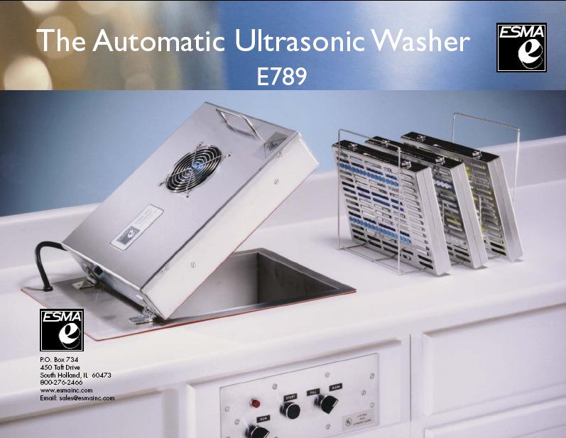
3 Instructions for Ultrasonic Washer E789 (U.L. Approved) 1. INTRODUCTION The E789 Automatic Ultrasonic Washer automatically performs a cleaning cycle, the major steps of which are: Ultrasonic cleaning Ultrasonic rinsing (hot tap water) Hot air drying The E789 unit has a primary rinse solenoid, which is connected to the hot tap water supply. The E789 is equipped with a chemical metering pump for precision distribution of the exact amount of liquid detergent concentrate. Use only Esma brand detergent concentrates when operating the E789 with metering pump. The result is a finished product ready for the next step (sterilizing, packaging, assembly, storage). The unit consists of four sections: 1) Tank Module-to be installed in the counter 2) Control Module-to be installed in front of counter 3) Power Module to be installed under the counter and 4) Metering Pump which is to be located under counter. The Tank Module is manufactured from 316 stainless steel with 12 potting transducers mounted on the bottom. The tank is equipped with two fill solenoids (E789 has only one), a drain solenoid and a low level control to prevent electronic damage if water pressure is lost. The tank is fitted with a 304 stainless hinged cover housing the fan and heater for airdrying. 3

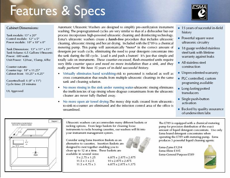
4 The Control Module is manufactured from 304 stainless and contains the switches to start the FILL or CLEAN cycles and stop the process manually, if needed. The Power Module contains the self-tuning modular circuit boards, programmable controller, high velocity fan to cool the electronics and RFI filter to eliminate high frequency noise. The Metering Pump is a Gorman-Rupp bellows metering pump. The supplied inlet tube from the metering pump should be inserted into a gallon jug of Esma cleaning solution concentrate. The pump is configured to meter a 1% concentrate during the fill cycle, approximately 180ml. Please use only proper detergent which is formulated for use with the E789 model. PLEASE READ THESE INSTRUCTIONS THOROUGHLY BEFORE INSTALLATION AND OPERATION. CALL IF YOU HAVE ANY QUESTIONS 2. INSTALLATION If the control module is to be placed directly in front of tank, allow 5 inches between counter opening and front of cabinet (diagram 1). Also, 28 inches of clearance is necessary under the counter for drains. Control Module - Cut opening of 4 ¼ x 10 ¼ in front of cabinet. The overall flange of unit on front of cabinet is 5 x 12, so center unit accordingly. Module will be mounted later with 4, No. 8 wood screws. Tank Module - Cut opening of 18 x 11 ¼ in top of counter. The overall flange of unit on top of counter is 20 x 13, so center unit accordingly. Place tank in opening and mark on counter the mounting studs welded under top plate. Remove tank and drill mounting holes with1/4 drill bit. Do not mount tank until control module opening is cut out. 4
5 Tank Module should be set in counter first. A gasket is glued to the underside of the top plate to prevent liquid from seeping into the counter. Place the tank-mounting studs into the pre-drilled holes in counter and tighten down with 8 x 32 nuts and washers, which are supplied. (DO NOT OVERTIGHTEN). Power Module measures 8 x 16 x 18 D. However, 1 of clearance is necessary both at the front and back of unit for proper ventilation. The electrical connections, from tank and control modules, attached to the top of the module, require additional 2 to 3 inches of space. The Metering Pump should be monitored to assure that there is solution in the jug. Due to the length of tubing, it will take one cycle for the metering pump to become primed. Once the pump is primed, a 1% solution concentrate will automatically be added to the water during the fill cycle. Please regularly check to make sure that there is adequate cleaning solution in the jug. 3. PLUMBING HOOK-UP A. Water Input (Diagrams 2 & 3, see last page) The primary solenoid should be connected to a hot water source. This solenoid has a ½ NPT female opening. A ½ MNPT x 3/4 MGH adapter has been supplied for hot water hookup using a standard washing machine water supply hose (not supplied). It is recommended that a filter washer be installed into the water supply hose to prevent sediment debris from entering solenoid from water source. The highpressure hose should connect the solenoid to a shut-off valve (not supplied) at you water source. A flow regulator is incorporated into the unit; therefore, the shut-off valve must not restrict the flow more than 3.5 GPM. Also, a backflow regulator (not supplied) may have to be attached at your water source to comply with local regulations. B. Water Output (Diagram 2, see last page) 5
6 1½ x 16 elbow (A), which is supplied, is to be attached with a slip nut (B) and washer (C) to the 1½ output nipple. (This piece can be hooked up prior to installation of the tank but that is not necessary. The tailpiece (D) with ¾ input (supplied) is to be attached to elbow (A) with a slip nut (E) and adapting washer (F). Attached to the tailpiece, with a hose clamp (G), will be 2 of ¾ hose (I). The other end of this hose is to be attached to be attached to hose adapter (H), with the hose clamp (G), after (H) is threaded into the drain solenoid using Teflon tape or joint compound. A P trap (not supplied) is then to be attached to tailpiece (D) prior to hookup to drain line. 4. ELECTRICAL The unit is rated at 1500 W, 120 VAC, 50/60 HZ. Only the power module is plugged into your 120VAC supply (diagram). The Tank Module has two plugs. Plug (K) goes to the underneath side of Control Module and attaches to receptacle (L). Plug (I) is attached to power module at receptacle (E). Control Module has two plugs, (M) and (N), which attach to receptacles (C) and (G) on the power module. Only the plug from power module (A) is to be connected to your power source. Unit must be electrically grounded. The power cord must be connected to a three-way grounded outlet. For 2-wire service, an adapter with external ground wire is necessary. Connect the green grounding wire of the adapter to the screw, which holds the electric outlet plate cover to the socket. DO NOT OPERATE UNIT WITHOUT PROPER GROUNDING. A fuse, 15AMP, 120VAC, is located on the power module. 5. CONTROL FUNCTION A. Main Switch: When unit is ready for operation, put the main switch to ON and the indicator light on the power and the Control Module will be ON. 6
7 B. Run-Stop Switch: Located on Control Module, must be in the RUN position for the programmable controller to operate. If during the program cycle you want to stop the process, turn switch to STOP position and the program cycle will discontinue. Move switch back to RUN position and program will START over at the beginning of the fill cycle when start button is pushed. Use run-stop switch only for emergency stopping of unit. C. Fill/Clean Switch: Must start at FILL position and push start button. After tank is filled move switch to CLEAN position. When instruments or parts are added, push START button and the clean cycle will begin. You cannot start the clean cycle if the fill cycle is not completed. This is a safety precaution so the ultrasonics will not operate without any liquid in the tank. 6. PRELIMINARY START-UP After plumbing is completed, conduct the following test to determine if there are any leaks in the system. A. Turn main power ON B. RUN-STOP switch to ON C. FILL/CLEAN switch to FILL D. Close cover Push START button and gradually open the inlet valve you installed in the rinse line to bleed the air out of the line; them immediately open valve completely. The unit has a flow control valve which allows 3.5GPM, so it is important that the inlet valve doesn t restrict the flow to less than 3.5GPM or the fill time will have to be increased. After 90 seconds, the fill solenoid will close, and the water will be up to the overflow drain opening. Possibly, the first time the inlet valve was not manually opened fast enough to allow 3.5GPM for the entire 90 seconds. To test the overflow-rinse line, leave FILL/CLEAN switch on FILL and push the start button and water will flow into tank for additional 90 seconds. Now you can check your plumbing for leaks. 7
.")
8 CAUTION: When conducting this leak test, make sure the power module is not under the plumbing in order to avoid getting the electronics wet. To test the drain plumbing, move FILL/CLEAN switch to CLEAN and push START button to start the ultrasonic cleaning cycles (make sure fan inlet and outlet of power module are not obstructed). The clean cycle will cavitate for 10 minutes before the tank will drain. The entire clean cycle and times are given in the procedure section. You can stop the clean cycle at any time by turning the RUN-STOP switch to STOP and the program will revert back to the beginning of the FILL CYCLE. 7. OPERATION The basic principle of operation is the enhancement and acceleration of the cleaning action through ultrasonic cavitations. Instruments, or parts to be cleaned, are placed in the basket (or cassette racks) and lowered into the tank. NEVER PLACE PARTS DIRECTLY ON THE BOTTOM OF THE TANK. The baskets and cassette racks have rubber supports to keep parts off bottom of tank. 8. PROCEDURE 1. Turn main power ON 2. Turn RUN-STOP switch to RUN. (Should remain in RUN position at all times. 3. Set FILL/CLEAN switch to FILL. 4. Verify that the metering pump inlet supply is inserted into a gallon jug of an approved Esma cleaning concentrate (see section on cleaning agents). 5. Lower basket with instruments, or parts, on support rack. 8
9 6. Close cover. 7. Push START button and water will enter the tank for 90 seconds. 8. At this point more instruments (or parts) could be added when available, or move FILL/CLEAN switch to CLEAN, push START button and the cleaning program will automatically proceed through the cycle as follows: E789 UNIT Function Time/Seconds 1. Ultrasonic cleaning Drain Fill Ultrasonic Ultrasonic/Rinse Ultrasonic Ultrasonic/Rinse Ultrasonic Drain Drain, Dryer, Fan Drain, Fan Buzzer 5 TOTAL 1835 seconds (30 ½ minutes) 10. DRYING Incoming air is heated in the tank cover to 160 F and forced by the fan through the tank chamber before exhausting through the tank cover. CAUTION: Do not touch the cover during the drying cycle because some areas will be hot. Also, NEVER place any towel or obstruction over the fan intake on cover. After 7 minutes of hot air drying, the parts are left in 9
10 the tank for 2 minutes to allow some cooling to take place before handling. The air temperature during the hot air drying can be increased or decreased by adjusting a thermo-switch located in dryer cover at hot air exit. Please contact manufacturer for more details. 10
11 11. PRESOAKING OF INSTRUMENTS For maximum effective cleaning, it is best if blood and other substances do not dry on the instruments. Therefore, fill the tank with hot water and cleaning agent and use the tank as a holding vessel for instruments until enough have accumulated to warrant cleaning. 12. CLEANING AGENT Use only Esma brand detergent concentrates when operating the E789 with metering pump. Esma produces 3 powerful liquid cleaning agents: Esma-Shine E105 Esma-General Purpose E589 Esma-Zyme E1240. DO NOT use powdered detergents; some powders take too long to go into solution. The metering pump is engineered to pump only the correct amount of detergent concentrate into the tank during the fill cycle. Esma brand detergents are formulated to meet the pump ratios. The metering pump has been factory calibrated to meter in 180ml of detergent concentrate during the fill cycle. By not using the correct cleaning agent problem can arise with final rinsing of parts if too much suds are generated. 13. LOW LEVEL SENSOR A low-level safety device is installed on the tank module to assure that the ultrasonics will not come on if there is less than three inches of water in the tank. A stainless probe is fixed in a Teflon plug mounted on the tank wall. When the liquid in the tank covers the probe the ultrasonics will activate during the clean or rinse cycles. Periodically, the probe should be wiped off to prevent insulating residues from cleaning agents, etc. from accumulating. 11
12 14. PROGRAMMABLE CONTROLLER An Omron Zen programmable controller (PLC) is used to control the FILL and CLEANING process. The memory protection maintains the program during power interruptions and a flash memory backup will save the program for 20 days at an ambient temperature of 77 F. PLC status indicators, located on top of the PLC, show the operating status according to the following table: Indicator Status Meaning POWER (green) ON Power is being supplied to the PLC. OFF Power isn t being supplied to the PLC. RUN (green) ON The PLC is operating in RUN or MONITOR mode. OFF The PLC is in PROGRAM mode or a fatal error has occurred. ERROR/ALARM (red) ON A fatal error has occurred. (PLC operation stops.) 15. MAINTENANCE Periodically, the drain screen in tank will have to be removed and cleaned. The accumulated lint and debris could slow down the draining enough so tank will not be emptied of cleaning solution when rinse cycle begins. Once a month, open power module and vacuum any dust that might have been drawn in by the fan. Never operate unit with cover of power module off. The tank is manufactured of 316SS and the modules of 304SS. Clean with a commercially available cleaner for stainless steel kitchen appliances. FOR ASSISTANCE CALL or
13 16. TROUBLE SHOOTING If there seems to be erratic behavior with a component, or if the fill and/or clean cycle seem to have changed, always go through the following procedure: o Turn RUN-STOP switch momentarily to STOP and then back to RUN. The program will now clear and revert to the beginning calling for a FILL CYCLE. Move FILL-CLEAN switch to FILL and push START regardless of if the tank has water in it. o If the problem persists, continue with trouble shooting or call manufacturer. If there is still a problem, look at the PLC located in the Power module. With MAIN switch ON and RUN-STOP in RUN position. Make sure that the POWER and RUN lights are ON. PROBLEM CAUSE REMEDY Particles or other accumulation has entered bleed line of solenoid Rinse solenoid is noisy, pulsating and little or no water coming into tank when output 00 is ON No ultrasonics when output 01 is ON. Large cooling fan in power module is ON. No ultrasonics when large cooling fan is OFF when output 01 is on Low water pressure Fuse blown on circuit boards. Low water level in tank has activated low level safety control Rise solenoid problem, or insufficient water supply. Solenoid needs to be cleaned out (see instruction sheet for fill solenoid) Make sure filter screen is in place prior to valve 5-10 PSI water pressure is required to operate solenoid Need repair check that cooling fan is operating during cleaning. As above (fill solenoid problem) In line fuse to PLC is blown. Relay for fan and circuit boards not working. Low-level safety control is faulty. Replace 1.5Amp/120V fuse Replace relay Clean deposit off probe 13
14 Contact manufacturer PROBLEM CAUSE REMEDY Dryer gets too hot Fan inlet on top off cover is blocked Remove obstacle Thermostat inside cover needs adjustment Dryer Fan not working with output 06 on Contact manufacturer Dryer is cool with output 03 ON Thermostat needs adjustment if there is some heat. Replace in-line fuse to PLC Contact manufacturer Relay in control module is faulty Replace relay Tank drains with output 02 OFF Debris lodged in drain solenoid Clean out solenoid (see instructions) and make sure drain screen in place in tank Tank does not drain with output 0N Drain screen clogged. Clean and replace screen. Y strainer clogged Solenoid not operating Clean out Y strainer In-line fuse to PLC is blown or clean out solenoid valve 14
15 INSTALLATION INSTRUCTIONS & CABINET REQUIREMENTS FOR ULTRASONIC WASHER MODEL E INTRODUCTION The units automatically perform a cleaning cycle, the major steps of which are: Ultrasonic cleaning Ultrasonic rinsing (hot tap water) Ultrasonic rinsing (deionized water)-unit E291 only Hot air drying The E789 unit has only one rinse solenoid (primary), which is connected to the hot tap water supply. The result is a finished product ready for the next step (sterilizing, packaging, assembly, storage). The unit consists of three sections: 1) Tank Module-to be installed in the counter 2) Control Module-to be installed in front of counter and 3) Power Module- to be installed under the counter. The Tank Module is manufactured from 316 stainless steel, with 12 potting transducers mounted on the bottom. The tank is equipped with two fill solenoids (E789 has only one), a drain solenoid and a low level control to prevent electronic damage if water pressure is lost. The tank is fitted with a 304 stainless hinged cover housing the fan and heater for air-drying. The Control Module is manufactured from 304 stainless and contains the switches to start the FILL or CLEAN cycles and stop the process manually, if needed. The Power Module contains the self-tuning modular circuit boards, programmable controller, high velocity fan to cool the electronics and RFI filter to eliminate high frequency noise. PLEASE READ THESE INSTRUCTIONS THOROUGHLY BEFORE INSTALLATION AND OPERATION. CALL (800) IF YOU HAVE ANY QUESTIONS. 2. INSTALLATION If the control module is to be placed directly in front of tank, allow 5 inches between counter opening and front of cabinet (diagram 1). Also, 28 inches of clearance is necessary under the counter for drains. Control Module-Cut opening of 4-1/4" x 10 1/4" in front of cabinet. The overall flange of unit on front of cabinet is 5" x 12", so center unit accordingly. Module will be mounted later with 4 No. 8 wood screws. Tank Module-Cut opening of 18" x 11-1/4" in top of counter. The overall flange of unit on top of counter is 20" x 13", so center unit accordingly. Place tank in opening and mark on counter the mounting studs welded underneath top plate. Remove tank and drill mounting holes with 1/4" drill bit. Do not mount tank until control module opening is cut out. Tank Module should be set in counter first. A gasket is glued to the underside of the top plate to prevent liquid from seeping into the counter. Place the tankmounting studs into the pre-drilled holes in counter and tighten down with 8 x 32 nuts and washers, which are supplied. (DO NOT OVERTIGHTEN). Power Module measures 8" x 16' x 18" D. However, I" clearance is necessary both at the front and back of unit for proper ventilation. The electrical connections from tank and control modules, attached to the top of the module, require additional 2 to 3 inches of space. 15
16 3. PLUMBING HOOK-UP A. Water Input (Diagrams 2 & 3, see last page) The primary solenoid should be connected to a hot water source. This solenoid has a 1/2" NPT female opening. An adapter and a high-pressure hose, with a filtered washer are supplied. The high-pressure hose should connect the solenoid to a shut-off valve (not supplied) at your water source. A flow regulator is incorporated into the unit, therefore, the shut-off valve must riot restrict the flow more than 3.5 GPM. Also, a backflow regulator (not supplied) may have to be attached at your water source to comply with local regulations. On Model E291 only, a deionized water source is connected to the secondary solenoid following the instructions given for the primary solenoid (Diagram 5). B. Water Output (Diagram 2, see last page) 1 1/2" x 16" elbow (A), which is supplied, is to be attached with a slip nut (B) and washer (C) to the 1 1/2" output nipple. (This piece can be hooked up prior to installation of the tank but that is not necessary). The tailpiece (D) with 3/4" input (supplied) is to be attached to elbow (A) with a slip nut (E) and an adapting washer (F). Attached to the tailpiece, with a hose clamp (G), will be 2' of 3/4 hose (1). The other end of this hose is to be attached to hose adapter (H), with the hose clamp (G), after (H) is threaded into the drain solenoid using Teflon tape or joint compound. A "P' trap (not supplied) is then to be attached to tailpiece (D) prior to hookup to drain line. 4. ELECTRICAL The unit is rated at 1500 W, 120 VAC, 50/60 HZ. Only the power module is plugged into your 120 VAC supply (diagram 4). The Tank Module has two plugs. Plug (K) goes to the under side of Control Module and attaches to receptacle (L). Plug (1) is attached to power module at receptacle (E). Control Module has two plugs, (M) and (N), which attach to receptacles (C) and (G) on the power module. Only the plug from power module (A) is to be connected to your power source. Unit must be electrically grounded. The power cord must be connected to a three-way grounded outlet. For 2- wire service, an adapter with external ground wire is necessary. Connect the green grounding wire of the adapter to the screw, which holds the electric outlet plate cover to the socket. DO NOT OPERATE UNIT WITHOUT PROPER GROUNDING. A fuse, 15 AMP 120 VAC, is located on the power module. 16
17 17
Celebrating over 30 years of excellence in manufacturing ultrasonic cleaning equipment, electropolishing equipment and associated chemistries
 Instructions for Ultrasonic Washer E397 & E397RC E498 & E498RC 1. INTRODUCTION The E397 and E498 units automatically perform a cleaning cycle, the major steps of which are: Ultrasonic Cleaning Ultrasonic
Celebrating over 30 years of excellence in manufacturing ultrasonic cleaning equipment, electropolishing equipment and associated chemistries
 Instructions for Model E1002 Ultrasonic Washer Introduction The Model E1002 ultrasonic washer is equipped to run timed cycles of clean, rinse and dry. The unit is housed in a 304 stainless steel cabinet.
Instructions for Model E782 Betman Cleaning System (Cleaner/Rinser/Rinser/Dryer)
") 1 2 Esma Inc. PO Box 734 450 W. Taft Drive South Holland, IL 60473 708-331-1855 800-276-2466 FAX 708-331-8919 Introduction Instructions for Model E782 Betman Cleaning System (Cleaner/Rinser/Rinser/Dryer)
1 2 Esma Inc. PO Box 734 450 W. Taft Drive South Holland, IL 60473 708-331-1855 800-276-2466 FAX 708-331-8919 Introduction Instructions for Model E782 Betman Cleaning System (Cleaner/Rinser/Rinser/Dryer)
COPPER FREESTANDING TUB
 COPPER FREESTANDING TUB INSTALLATION INSTRUCTIONS AND CARE GUIDE CONTENTS Tub Installation...2 Rough-In...2 Drain Installation...3 Drain without Overflow...3 Waste and Overflow Drain...3 Trimming Drain
BUILT-IN DISHWASHER INSTALLATION INSTRUCTIONS
 BUILT-IN DISHWASHER INSTALLATION INSTRUCTIONS PLEASE READ COMPLETE INSTRUCTIONS BEFORE YOU BEGIN LEAVE INSTALLATION INSTRUCTIONS AND USER'S GUIDE WITH OWNER ALL ELECTRIC WIRING AND PLUMBING MUST BE DONE
Installation Instructions. For the 18 Built-In Dishwasher and Front Color Panels
 Installation Instructions For the 18 Built-In Dishwasher and Front Color Panels Printed in USA 154232102 Before You Begin DO NOT INSTALL DISHWASHER UNTIL YOU HAVE READ ALL INSTRUCTIONS. FOR YOUR SAFETY,
Series 47 and 247 Mechanical Water Feeders. Series 47-2 and Combination Mechanical Water Feeder/Low Water Cut-Off ! WARNING
 Series 47 and 247 Mechanical Water Feeders McDonnell & Miller Installation & Maintenance Instructions MM-316(C) Series 47-2 and 247-2 Combination Mechanical Water Feeder/Low Water Cut-Off Series 47 Water
SAFETY OPERATION & MAINTENANCE MANUAL X-612 CARPET EXTRACTOR
 SAFETY OPERATION & MAINTENANCE MANUAL X-612 CARPET EXTRACTOR W/PARTS LIST This unit is intended for commercial use. READ AND FOLLOW ALL INSTRUCTIONS, WARNINGS AND CAUTIONS BEFORE USING THIS EXTRACTOR Address:
SAFETY OPERATION & MAINTENANCE MANUAL X-405 CARPET EXTRACTOR This unit is intended for commercial use.
 SAFETY OPERATION & MAINTENANCE MANUAL X-405 CARPET EXTRACTOR This unit is intended for commercial use. READ AND FOLLOW ALL INSTRUCTIONS, WARNINGS AND CAUTIONS BEFORE USING THIS EXTRACTOR Address: 777 South
Installation Instructions
 Installation Instructions For the 18" Built-In Dishwasher Sears, Roebuck and Co. Sears Canada, Inc. Hoffman Estates, IL 60179 U.S.A. Toronto, Ontario, Canada M5B 2B8 154435201 Before You Begin DO NOT INSTALL
Rules for Safe Operation
 Rules for Safe Operation Important: Do not attempt to operate the CleanStation until you have read thoroughly and understand all instructions and safety rules contained in this manual. Failure to comply
Liberty-Classic. Operator s Manual
 Liberty-Classic Operator s Manual Pure & Secure LLC 4120 NW 44th Lincoln, NE 68524 Phone: 402-467-9300 Fax: 402-467-9393 2006, Pure & Secure LLC. All Right Reserved Table of Contents Important Safety
INSTALLATION AND OPERATION MANUAL STEAM COIL BASE CONVECTION STEAMER MODEL SCX-16
 INSTALLATION AND OPERATION MANUAL STEAM COIL BASE CONVECTION STEAMER MODEL SCX-16 CROWN FOOD SERVICE EQUIPMENT LTD. 70 OAKDALE ROAD, DOWNSVIEW, (TORONTO), ONTARIO, CANADA, M3N 1V9 TELEPHONE: (416) 746-2358,
3500 SERIES CONVECTION STEAM COOKER PARTS AND SERVICE MANUAL
 3500 SERIES CONVECTION STEAM COOKER PARTS AND SERVICE MANUAL EFFECTIVE JULY 30, 2014 Superseding All Previous Parts Lists. The Company reserves the right to make substitution in the event that items specified
INSTALLATION INSTRUCTIONS UNDERCOUNTER DISHWASHERS
 INSTALLATION INSTRUCTIONS UNDERCOUNTER DISHWASHERS VIKING 111 Front Street Greenwood, Mississippi 38930 USA (662) 455-1200 IMPORTANT - PLEASE READ AND FOLLOW Before beginning - please read these instructions
CELDEK Evaporative Cooler Module Installation, Operation, and Maintenance Manual. CELDEK Evaporative Cooler
 CELDEK Evaporative Cooler Module Installation, Operation, and Maintenance Manual CELDEK Evaporative Cooler RECEIVING AND INSPECTION Upon receiving unit, check for any interior and exterior damage, and
PS-3E AND PS-6E ELECTRIC CONVECTON STEAMERS PARTS AND SERVICE MANUAL
 PS-3E AND PS-6E ELECTRIC CONVECTON STEAMERS PARTS AND SERVICE MANUAL EFFECTIVE AUGUST 1, 2014 Superseding All Previous Parts Lists. The Company reserves the right to make substitution in the event that
Standard and CELDEK Evaporative Cooler Modules Installation, Operation, and Maintenance Manual
 Standard and CELDEK Evaporative Cooler Modules Installation, Operation, and Maintenance Manual Standard Evaporative Cooler CELDEK Evaporative Cooler RECEIVING AND INSPECTION Upon receiving unit, check
PUREPOWER SERIES CENTRAL VACUUM POWER UNITS PP500, PP600 & PP650
 USER GUIDE PUREPOWER SERIES CENTRAL VACUUM POWER UNITS PP500, PP600 & PP650 AB0039 FOR RESIDENTIAL USE ONLY!! MODELS SFDB-DQ, SFDB-DR AND SFDB-DS 30042509E IMPORTANT SAFETY INSTRUCTIONS SAVE THESE INSTRUCTIONS
(PD[ $LU 'U\HU 5 ( ) 5, * ( 5 $ 7 ( ' 7 < 3 ( & ( 6 6 ( ' $, 5 ' 5 < ( 5 6 ('5&) ದ ('5&) Instructions Manual
 5, * ( 5 $ 7 ( ' 7 < 3 ( & ( 6 6 ( ' $, 5 ' 5 < ( 5 6 ('5&) ದ ('5&) Instructions Manual") Instructions Manual 1. Important safety notes - Please read... 1 1.1. Transportation... 1 1.2 Positioning... 1 1.3 Installation... 1 1.4 Before operating... 1 1.5 Maintenance by an engineer... 1 1.6 Maintenance
Instructions Manual 1. Important safety notes - Please read... 1 1.1. Transportation... 1 1.2 Positioning... 1 1.3 Installation... 1 1.4 Before operating... 1 1.5 Maintenance by an engineer... 1 1.6 Maintenance
COBRA -300H EXTRACTOR
 COBRA -300H EXTRACTOR 120V INFORMATION & OPERATING INSTRUCTIONS DO NOT OPERATE MACHINE UNTIL YOU HAVE READ ALL SECTIONS OF THIS INSTRUCTIONS IMPROPER USE OF THE MACHINE WILL VOID THE WARRANTY 1. Always
RESIN FREESTANDING TUB
 RESIN FREESTANDING TUB INSTALLATION INSTRUCTIONS AND CARE GUIDE CONTENTS Tub Installation...2 Rough-In...2 Drain Installation...3 Air Tub Installation...4 Electrical Installation...4 Remote Control Installation...5
Electrical cable Water supply tube Fittings for tube Coupler Teflon tape. Hole saw min. 2½" bit
 Installation Parts and Tools Parts not Provided Electrical cable Water supply tube Fittings for tube Coupler Teflon tape Air gap Wire nuts for 6-gauge wiring Hose clamp ⅞" UL approved strain relief Electrical
GREASE INTERCEPTORS. Z1192 GREASE RECOVERY APPLIANCE (GRA) INSTALLATION and OPERATION INSTRUCTIONS
 INSTALLATION and OPERATION INSTRUCTIONS") Z1192 GREASE RECOVERY APPLIANCE (GRA) INSTALLATION and OPERATION INSTRUCTIONS Note: Zurn Grease Interceptors with grease recognizing sensors are efficient appliances designed to separate grease from water.
Z1192 GREASE RECOVERY APPLIANCE (GRA) INSTALLATION and OPERATION INSTRUCTIONS Note: Zurn Grease Interceptors with grease recognizing sensors are efficient appliances designed to separate grease from water.
CFX-27 GALLON PORTABLE EXTRACTOR. Owner s Manual CFX 1/22/2010
 ` CFX-27 GALLON PORTABLE EXTRACTOR Owner s Manual CFX 1/22/2010 1 Overview The Rotovac CFX-27 has an extra large 27 gallon clean water holding tank and an automatic waste water pump out system. In addition,
Polar Air Dryer. Instructions Manual PDRCF PDRCF R E F R I G E R A T E D T Y P E C O M P R E S S E D A I R D R Y E R S
 Polar Air Dryer R E F R I G E R A T E D T Y P E C O M P R E S S E D A I R D R Y E R S PDRCF1150029 PDRCF4602000 Instructions Manual TABLE OF CONTENTS 1. Important safety notes - Please read... 1 1.1. Transportation...
2364 Leicester Road, P.O. Box 175, Leicester, NY Phone (585) Fax (585)
 Fax (585)") Dry Heat Sterilizers with 60 Minute Sterilization Cycle Times MODEL 3100 MODEL 2100 2364 Leicester Road, P.O. Box 175, Leicester, NY 14481 Phone (585) 382-3223 Fax (585) 382-9481 www.cpac.com December
Dry Heat Sterilizers with 60 Minute Sterilization Cycle Times MODEL 3100 MODEL 2100 2364 Leicester Road, P.O. Box 175, Leicester, NY 14481 Phone (585) 382-3223 Fax (585) 382-9481 www.cpac.com December
TURBOWASH TM... Pot and Pan Sink
 TURBOWASH TM... Pot and Pan Sink MODEL TW ML-110644 701 S. RIDGE AVENUE TROY, OHIO 45374-0001 FORM 33800 Rev. A (4-98) Installation, Operation, and Care of TurboWash TM Pot and Pan Sink SAVE THESE INSTRUCTIS
VIKING RANGE CORPORATION, P.O. DRAWER 956, GREENWOOD, MS USA
 VIKING RANGE CORPORATION, P.O. DRAWER 956, GREENWOOD, MS. 38930-USA TABLE OF CONTENTS Model / Serial Number... 3 Cycle Options... 3 Superclean System... 5 Trouble Shooting... 5 Voltage / Resistance Readings...
Technical Data TYPE T14 & T14D TEMPERATURE PILOT SPENCE ENGINEERING COMPANY, INC. 150 COLDENHAM ROAD, WALDEN, NY SD 4511A T14 PILOT
 Technical Data SD 4511A SPENCE ENGINEERING COMPANY, INC. 150 COLDENHAM ROAD, WALDEN, NY 12586-2035 TYPE T14 & T14D TEMPERATURE PILOT PRINTED IN U.S.A. SD 4511A/9811 5 13 /16 D 4 7 /8 1 13 /16 T14 PILOT
OWNER S MANUAL AND INSTALLATION GUIDE PLEASE READ THIS MANUAL CAREFULLY BEFORE ATTEMPTING INSTALLATION
 ClearChoice Economy Under Sink Drinking Water System OWNER S MANUAL AND INSTALLATION GUIDE PLEASE READ THIS MANUAL CAREFULLY BEFORE ATTEMPTING INSTALLATION Congratulations on the purchase of your ClearChoice
PUREPOWER SERIES CENTRAL VACUUM POWER UNITS PP500, PP600 & PP650
 USER GUIDE PUREPOWER SERIES CENTRAL VACUUM POWER UNITS PP500, PP600 & PP650 AB0039 FOR RESIDENTIAL USE ONLY!! BROAN-NUTONE LLC; HARTFORD, WISCONSIN WWW.NUTONE.COM 1-888-336-3948 REGISTER YOUR PRODUCT ONLINE
OUTDOOR DISHWASHER INSTALLATION INSTRUCTIONS
 OUTDOOR DISHWASHER INSTALLATION INSTRUCTIONS IMPORTANT! Read all of these instructions before installing the dishwasher. AUTOMATIC HIGH LOOP The drain hose is fastened to the back of the machine at the
Top Control Dishwasher
 INSTALLATION GUIDE Top Control Dishwasher NS-DWH2BS8/NS-DWH2SS8/NS-DWR2BS8/NS-DWR2WH8/NS-DWR2SS8 Before using your new product, please read these instructions to prevent any damage. Contents Introduction......................................................................................................
IMPORTANT WARNINGS IMPORTANT SAFETY INSTRUCTIONS
 IMPORTANT WARNINGS IMPORTANT SAFETY INSTRUCTIONS Suncourt recommends professional installation of the Airiva (or by an accomplished DIY person) Please read and save these entire instructions before starting
B.I.C.A Built-In Coffee Appliance
 B.I.C.A Built-In Coffee Appliance Automatic Coffee Brewer Parts & Service Models: 1033510, 1033510S & 1033511 3828 S. Main St. Los Angeles, CA 90037-1491 800-421-6860 310-787-5444 Fax 310-787-5412 e-mail:
Remote Water Quality System Standard Equipment (supplied by EPI) Remote Water Quality System Optional Equipment (supplied by EPI)
 Remote Water Quality System Optional Equipment (supplied by EPI)") Page 1 of 11 Parts List Remote Water Quality System Standard Equipment (supplied by EPI) 20sq ft Skimmer-Filter Remote Water Quality Plumbing Kit Heater-Controller Keypad Control 220V 3/4HP Circulation
Page 1 of 11 Parts List Remote Water Quality System Standard Equipment (supplied by EPI) 20sq ft Skimmer-Filter Remote Water Quality Plumbing Kit Heater-Controller Keypad Control 220V 3/4HP Circulation
ECOJET EJ-10E & EJ-7E ELECTRIC CONVECTION STEAMER W/TWIN GENERATORS PARTS AND SERVICE MANUAL
 ECOJET EJ-10E & EJ-7E ELECTRIC CONVECTION STEAMER W/TWIN GENERATORS PARTS AND SERVICE MANUAL EFFECTIVE JULY 31, 2014 Superseding All Previous Parts Lists. The Company reserves the right to make substitution
Installation & Operation
 2 PVC Vent Pipe 2 PVC Vent Connection (Vent connected to outdoors) 65 (165cm) Conduit (Provided) Disconnect Box (Provided By Electrician) (1 box per pump) 1/4 Comp x 1/4 Comp x 60 (153cm) See notes on
ACRYLIC CLAWFOOT TUB
 ACRYLIC CLAWFOOT TUB INSTALLATION INSTRUCTIONS AND CARE GUIDE CONTENTS Tub Installation...2 Rough-In...2 Drain Installation...3 Drain without Overflow...3 Waste and Overflow Drain...3 Trimming Drain Pipes...4
Ultrasonic Humidification System Model 5462 & Model 5472 OPERATING MANUAL
 Ultrasonic Humidification System Model 5462 & Model 5472 OPERATING MANUAL 6/30/06 www.electrotechsystems.com TABLE OF CONTENTS 1.0 General Page 01 2.0 Description 01 3.0 Set-Up 01 4.0 Model 5462 03 4.2
Standard and CELDEK Evaporative Cooler Modules Installation, Operation, and Maintenance Manual
 Standard and CELDEK Evaporative Cooler Modules Installation, Operation, and Maintenance Manual Standard Evaporative Cooler CELDEK Evaporative Cooler RECEIVING AND INSPECTION Upon receiving unit, check
Safety. Rinse Kit for Multi-Pro 1200 and 1250 Turf Sprayers Model No Safety and Instructional Decals. Installation Instructions
 Rinse Kit for Multi-Pro 1200 and 1250 Turf Sprayers Model No. 106-4842 Form No. 3353-529 Rev B Installation Instructions Note: Determine the left and right sides of the machine from the normal operating
Installation, Operation, and Maintenance Manual RTE14S & RTE14S-2. For the Taco Bell "Rethermalizer" Model Numbers
 Installation, Operation, and Maintenance Manual For the Taco Bell "Rethermalizer" Model Numbers RTE14S & RTE14S-2 NOTICES There are three different types of notices that you should be familiar with, a
Up to 60 Pint Commercial Grade DEHUMIDIFIER
 OWNER S MANUAL Up to 60 Pint Commercial Grade DEHUMIDIFIER Product #700834 IMPORTANT: After unpacking (or accidental tip-over) allow dehumidifier to stand upright for 20 minutes before starting. Contents
OPERATING MANUAL. Reverse Osmosis Equipment Model: Frame Mount Vertical FMV-1 through FMV-6. Made in U.S.A.
 OPERATING MANUAL Reverse Osmosis Equipment Model: Frame Mount Vertical FMV-1 through FMV-6 Made in U.S.A. TABLE OF CONTENTS Model: Frame Mount Vertical COMPONENT IDENTIFICATION Page 1 IMAGE OF R. O. SYSTEM
PLEASE READ CAREFULLY THE INSTRUCTIONS BEFORE OPERATING
 1 2 ESMA INC PO BOX 734 450 W. Taft Dr. South Holland IL 60473 1-800-276-2466 708-331-1855 INSTRUCTIONS FOR ELECTROPOLISHER E399 Introduction The E399 unit polishes stainless or chrome-cobalt alloys with
USER MANUAL WATER DISPENSER WITH ICE MAKER
 USER MANUAL WATER DISPENSER WITH ICE MAKER Model:048-GM-48200 Please read this owner s manual carefully before operating the unit. TABLE OF CONTENTS INTRODUCTIONS... 3 IMPORTANT SAFETY INSTRUCTIONS.. 3
SuperKlean Washdown Products
 February 2012 DURAMIX 8000 INSTALLATION AND MAINTENANCE INSTRUCTIONS **DO NOT THROW AWAY AFTER INSTALLATION** **SAVE AND DISPLAY PROMINENTLY WHERE THIS EQUIPMENT IS USED** WARNING HIGH PRESSURE AND HOT
Control Panel For Water Wash Hoods AM2
 Control Panel For Water Wash Hoods AM2 For further information Call: (919) 554-1025 Or Fax: (919)554-1525 Aqua-Matic 117 Franklin Park Ave. Youngsville, NC 27506 TABLE OF CONTENTS AQUA-MATIC LIMITED WARRANTY
CLe-series Dishwashers
 CLe-series Dishwashers Blower-dryer electric (CLe SERIES) ML-138211 ML-138212 ML-138213 ML-138214 electric (CLeR SERIES) ML-138325 ML-138326 ML-138327 ML-138328 STEAM (CLe SERIES) ML-138226 ML-138227 ML-138228
Mobile Air Conditioner Instruction Manual Model TC-N9KM
 Mobile Air Conditioner Instruction Manual Model TC-N9KM Please read and retain these instructions for future reference SPECIFICATION Model no. Cooling capacity Power/Ampere consumption for cooling* Air
Installation Instructions
 Salvajor S914 Scrap Collector A Scrapping, Pre-flushing and Food Waste Collecting System 2 Table Installation and Location 3 Plumbing 4 Electrical 5 Operating Instructions 6 Typical Installations 8 Warranty
TURBOWASH TM... Pot and Pan Sink
 TURBOWASH TM... Pot and Pan Sink MODEL TWII ML-110971 701 S. RIDGE AVENUE TROY, OHIO 45374-0001 937 332-3000 www.hobartcorp.com FORM 34504 Rev. B (June 2002) Installation, Operation, and Care of TurboWash
MODEL A5-2 SOLVENT & WATER RECOVERY SYSTEMS (EXPLOSION PROOF UNITS)
") MODEL A5-2 SOLVENT & WATER RECOVERY SYSTEMS (EXPLOSION PROOF UNITS) FOR PROPER AND SAFE USE OF THIS CHEMCHAMP EQUIPMENT, PLEASE FOLLOW THIS DOCUMENT AND LOCAL AUTHORITY. KEEP THIS DOCUMENT FOR FUTURE REFERENCE.
MODEL A5-2 SOLVENT & WATER RECOVERY SYSTEMS (EXPLOSION PROOF UNITS) FOR PROPER AND SAFE USE OF THIS CHEMCHAMP EQUIPMENT, PLEASE FOLLOW THIS DOCUMENT AND LOCAL AUTHORITY. KEEP THIS DOCUMENT FOR FUTURE REFERENCE.
Installation Instructions Built-In Dishwasher
 GE Consumer & Industrial Appliances Installation Instructions Built-In Dishwasher If you have questions, call 800.GE.CARES (800.432.2737) or visit our website at: www.ge.com BEFORE YOU BEGIN Read these
INSTALLATION AND OPERATING INSTRUCTIONS FOR RW519 RAIN WATER FILTRATION SYSTEM
 INSTALLATION AND OPERATING INSTRUCTIONS FOR RW519 RAIN WATER FILTRATION SYSTEM INSTALLATION CAUTIONS Installation must conform to all local and state plumbing codes and regulations. Please read carefully
SITE REQUIREMENTS & INSTALLATION DSD-201 & SSD-102
 Instructions SITE REQUIREMENTS & INSTALLATION DSD-201 & SSD-102 The purpose of this section is to provide the customer with requirements that need to be met before the DSD/SSD can be properly installed.
SHURFLO BLASTER II MARINE WASHDOWN PUMP PRODUCT TECHNICAL DATA SHEET
 SHURFLO BLASTER II MARINE WASHDOWN PUMP PRODUCT TECHNICAL DATA SHEET OEM: AFTERMARKET: 8-11-A07 8-11-E07 APPLICATION: Marine fresh or salt water wash-down installation. This pump may be used for general
WD7664 / WD7663 Maxon Burner Ellis Whisper Dryer Installation & Start UP
 WD7664 / WD7663 Maxon Burner Ellis Whisper Dryer Installation & Start UP Receiving Do a quick visual inspection on the truck for any major damage prior to signing the paperwork. Damage should be noted
INSTRUCTION MANUAL Model: SU3022
 INSTRUCTION MANUAL Model: SU3022 GUARANTEE This product is guaranteed for 2 years from the date of original purchase. If any defect arises due to faulty materials or workmanship, the unit will, either
SAFE DRINKING WATER AND TOXIC ENFORCEMENT ACT
 Installation instructions for your new Spacemaker Laundry WSM2780 Gas Before you begin Read these instructions completely and carefully. IMPORTANT OBSERVE ALL GOVERNING CODES AND ORDINANCES. Note to Installer
OWNERS GUIDE TO INSTALLATION AND OPERATION
 OWNERS GUIDE TO INSTALLATION AND OPERATION SPM SERIES HIGH POWER CENTRIFUGALS READ THESE INSTRUCTIONS CAREFULLY Read these installation instructions in detail before installing your pump. Be sure to check
Fountain Classic. Installation and Owner s Manual. Page 16
 Fountain Classic Installation and Owner s Manual Page 16 4120 NW 44th St Lincoln, NE 68524 USA Tel: 402.467.9300 Toll Free in the USA: 800.875.5915 Fax: 402.467.9393 www.purewaterinc.com Page 2 Fountain
ALTAIR II CONVECTION STEAM COOKER PARTS AND SERVICE MANUAL
 ALTAIR II CONVECTION STEAM COOKER PARTS AND SERVICE MANUAL EFFECTIVE MAY, 0 Superseding All Previous Parts Lists. The Company reserves the right to make substitution in the event that items specified are
HP310-C EXTRACTOR 120V
 HP310-C EXTRACTOR 120V 1 2 3 VAC 1 VAC 2 PUMP INFORMATION & OPERATING INSTRUCTIONS DO NOT OPERATE MACHINE UNTIL YOU HAVE READ ALL SECTIONS OF THIS INSTRUCTIONS IMPROPER USE OF THE MACHINE WILL VOID THE
Gen II Entree Bath - All Models
 Gen II Entree Bath - All Models Installation Manual Important Safety Instructions Read & Follow All Instructions Thoroughly Important safety instructions. Read and follow all instructions thoroughly. CAUTION:
OPERATING AND MAINTENANCE MANUAL FOR ELECTRIC STAINLESS STEEL HEATER FOR DEIONIZED (DI) WATER ELECTRIC HEATER COMPANY BASE MODEL D
 WATER ELECTRIC HEATER COMPANY BASE MODEL D") OPERATING AND MAINTENANCE MANUAL FOR ELECTRIC STAINLESS STEEL HEATER FOR DEIONIZED (DI) WATER ELECTRIC HEATER COMPANY BASE MODEL D HUBBELL ELECTRIC HEATER COMPANY P.O. BOX 288 STRATFORD, CT 06615 PHONE:
OPERATING AND MAINTENANCE MANUAL FOR ELECTRIC STAINLESS STEEL HEATER FOR DEIONIZED (DI) WATER ELECTRIC HEATER COMPANY BASE MODEL D HUBBELL ELECTRIC HEATER COMPANY P.O. BOX 288 STRATFORD, CT 06615 PHONE:
Patriot. Automatic Pool Vacuum Cleaner. Patent No. 5,794,293. Owner's Guide. Model *Recommended for 3/4 HP and above
 Patriot Model 5-2046-000 Automatic Pool Vacuum Cleaner Patent No. 5,794,293 Owner's Guide *Recommended for 3/4 HP and above 365-1926-1 CAUTIONS 1. Remove the vacuum from the pool prior to super chlorinating
Item # Modular Blast CaBinEt instructions
 Item #20464 Modular Blast CaBinEt instructions The Eastwood Modular Blast Cabinet is specifically designed with heavy-duty components and a quality powdercoated finish to provide years of trouble free
Installation Manual CARBONATOR With Plain-Water Booster
 CORNELIUS INC One Cornelius Place Anoka, MN 55303-6234 Telephone (800) 238-3600 Facsimile (763) 422-3246 Installation Manual CARBONATOR With Plain-Water Booster IMPORTANT: It is the responsibility of the
Installation Instructions
 GE Consumer & Industrial Appliances Installation Instructions Junction Box Cover Within this user bag, you will find a junction box cover and a #10 hex head screw used to attach the junction box cover
Glass and Dishwashers 402/452/502. (original instructions) (incl. Australian /502) Starting from Serial No.:
 (incl. Australian /502) Starting from Serial No.:") Glass and Dishwashers ECOMAX 402/452/502 (incl. Australian 452-90/502) INSTALLATION AND OPERATION INSTRUCTIONS (original instructions) Starting from Serial No.: 8663 4000 REV. 05.10.2015 EN IMPORTANT NOTES
Glass and Dishwashers ECOMAX 402/452/502 (incl. Australian 452-90/502) INSTALLATION AND OPERATION INSTRUCTIONS (original instructions) Starting from Serial No.: 8663 4000 REV. 05.10.2015 EN IMPORTANT NOTES
AM60E DISHWASHER INSTALLATION AND OPERATION INSTRUCTION
 AM60E DISHWASHER INSTALLATION AND OPERATION INSTRUCTION HOBART FOOD EQUIPMENT CO.,LTD FORM 7153069XE V1.1 2012.08 AM60E DISHWASHER OPERATION INSTRUCTION 1 AM60E DISHWASHER OPERATION INSTRUCTION CONTENT
MODEL E
 www.burcam.com 2190 Dagenais Blvd. West TEL: 514.337.4415 LAVAL (QUEBEC) FAX: 514.337.4029 CANADA H7L 5X9 info@burcam.com Your pump has been carefully packaged at the factory to prevent damage during shipping.
Instruction Manual - Anti-Siphon Ejector Chlorine & Sulfur Dioxide 500 PPD (10 kg/h) Maximum Capacity
 Maximum Capacity") - Anti-Siphon Ejector Chlorine & Sulfur Dioxide 500 PPD (10 kg/h) Maximum Capacity 100 PPD (2 kg/h) Chlorine or Sulfur Dioxide 250 & 500 PPD (5 & 10 kg/h) Chlorine or Sulfur Dioxide Anti-Siphon Ejector
- Anti-Siphon Ejector Chlorine & Sulfur Dioxide 500 PPD (10 kg/h) Maximum Capacity 100 PPD (2 kg/h) Chlorine or Sulfur Dioxide 250 & 500 PPD (5 & 10 kg/h) Chlorine or Sulfur Dioxide Anti-Siphon Ejector
FOR SERVICE TECHNICIAN ONLY DO NOT REMOVE OR DESTROY WARNING
 WARNING Electrical Shock Hazard Disconnect power before servicing. Replace all parts and panels before operating. Failure to do so can result in injury or death. IMPORTANT Electric Discharge (ESD) Sensitive
MIRAI EXTRACTOR 100V DO NOT OPERATE MACHINE UNTIL YOU HAVE READ ALL SECTIONS OF THESE INSTRUCTIONS IMPROPER USE OF THE MACHINE WILL VOID THE WARRANTY
 MIRAI EXTRACTOR 100V LOCATOR 1 2 3 4 MODE VAC 1 VAC 2 PUMP BYPASS INFORMATION & OPERATING INSTRUCTIONS DO NOT OPERATE MACHINE UNTIL YOU HAVE READ ALL SECTIONS OF THESE INSTRUCTIONS IMPROPER USE OF THE
J120 STEAM BOOSTER INSTALLATION, OPERATION, AND SERVICE MANUAL J120 STEAM BOOSTER. J120 Steam Booster Manual D
 INSTALLATION, OPERATION, AND SERVICE MANUAL J120 STEAM BOOSTER J120 STEAM BOOSTER J120 Steam Booster Manual REVISION HISTORY Revision Letter Revision Date Made by Applicable ECNs Details A 10-27-04 CBW
INSTALLATION & MAINTENANCE MANUAL FOR QuickDraw
 INSTALLATION & MAINTENANCE MANUAL FOR QuickDraw SEMI-INSTANTANEOUS ENERGY: STEAM TO WATER U-TUBE SINGLE-WALL & DOUBLE-WALL HEAT EXCHANGERS FLOOR DRAIN Typical Construction Figure 34-1 FLOOR DRAIN 1. U-tube
Installation Instructions
 Installation Instructions 6 KW and 11.5KW Basic Circulation Water Heater and Pump Application: The Basic Circulation Water Heater has been in use for nearly 50 years, and it is the most prevalent model
Installation Instructions
 Instructions for Topload Washers Original Instructions Keep These Instructions for Future Reference. CAUTION: Read the instructions before using the machine. (If this machine changes ownership, this manual
Wilbur Curtis Company, Inc. Service Manual WB5GT Water Boiler
 Wilbur Curtis Company, Inc. Service Manual WB5GT Water Boiler Important Safeguards/Symbols This equipment is designed for commercial use. Any servicing other than cleaning and routine maintenance should
MODEL CMA-180UC SERVICE & PARTS MANUAL Rev 1.10
 MODEL CMA-180UC SERVICE & PARTS MANUAL Rev 1.10 CMA DISHMACHINES 12700 KNOTT AVENUE GARDEN GROVE, CALIFORNIA 92841 800-854-6417 FAX 714-895-2141 www.cmadishmachines.com 0203 TABLE OF CONTENTS MODEL CMA-180UC
XLT-60 EXTRACTOR 120V CAUTION: DO NOT OPERATE MACHINE UNTIL YOU HAVE READ ALL SECTIONS OF THIS INSTRUCTION MANUAL
 XLT-60 EXTRACTOR 120V INFORMATION & OPERATING INSTRUCTIONS CAUTION: DO NOT OPERATE MACHINE UNTIL YOU HAVE READ ALL SECTIONS OF THIS INSTRUCTION MANUAL 56041883 IMPROPER USE OF THE MACHINE WILL VOID THE
Rapid Heat Sterilizers with 6, 8, and 12 Minute Sterilization Cycle Times
 Rapid Heat Sterilizers with 6, 8, and 12 Minute Sterilization Cycle Times USER MANUAL MODELS: COX 115V-N COX 220V-N COX 115V-R COX 220V-R 2364 Leicester Road, P.O. Box 175, Leicester, NY 14481 Phone (585)
Water Boilers ME10EN, ME15EN. Table of Contents
 Water Boilers ME10EN, ME15EN Operator Manual Model ME15EN Model ME10EN Safety Information...2 Rough-In Drawing...3 Installation...4 Priming...5 Cleaning...5 Table of Contents Adjustments...6 Maintenance...7
INSTALLATION INSTRUCTIONS
 Web Site: http//www.atomic4.com e-mail: thomas.stevens@cox.net INSTALLATION INSTRUCTIONS INDIGO ELECTRONICS AT-4T THERMOSTAT KIT ATOMIC 4 - MECHANICAL FWC This Indigo Thermostat Kit is designed for use
Model HC-2. Crathco Whipped Hot Chocolate Dispenser. Table of Contents. Operation and Instruction Manual. for
 Crathco Whipped Hot Chocolate Dispenser Operation and Instruction Manual Table of Contents Introduction...1 Specifications...2 Installation and Start-Up Procedures...2 How to Dispense Hot Chocolate...3
WD7664 / WD7663 Maxon Burner. Ellis Whisper Dryer Installation & Start UP
 Title WD7664 / WD7663 Maxon Burner Ellis Whisper Dryer Procedure No. Installation & Start UP Procedure Author Chris Giordano Effective 1/23/17 Revision A Submitted By Chris Giordano Supersedes Date Revision
Niles Steel Tank Hot Water Generator Installation and Operation Manual
 Niles Steel Tank Hot Water Generator Installation and Operation Manual Contents: Contents 1 Hazard definitions 1 1. General Information.... 2 Availability... 3 Optional Control Packages... 5 2. Installation....
CAUTION: DO NOT OPERATE MACHINE UNTIL YOU HAVE READ ALL SECTIONS OF THIS INSTRUCTION MANUAL
 KING COBRA 310 120V INFORMATION & OPERATING INSTRUCTIONS U. S. PRODUCTS CAUTION: DO NOT OPERATE MACHINE UNTIL YOU HAVE READ ALL SECTIONS OF THIS INSTRUCTION MANUAL 56041963 IMPROPER USE OF THE MACHINE
TABLE 1 Electrical Specifications
 CHRONOMITE HIGH CAPACITY INSTANT-TEMP WATER HEATERS INSTALLATION AND OPERATION INSTRUCTIONS (208-240V Models) (Before installation, compare electrical requirements needed for the model of heater selected)
L A signature series TA T N E RE O, A L L A T S IN
 signature series COMMERCIAL STEAM GENERATORS INSTALLATION, OPERATION AND MAINTENANCE MANUAL INSTALLATION MANUAL COMMERCIAL STEAM GENERATOR SIGNATURE SERIES (SS) INTRODUCTION Steam Sauna manufactures steam
Diamond Whirlpool/Air pool INSTALLATION & OPERATION INSTRUCTION
 Diamond Whirlpool/Air pool INSTALLATION & OPERATION INSTRUCTION WARNING When using this unit, precautionary steps should be followed to prevent electrical shock or personal injury. 1. Do not permit children
CNA-Series - Large Industrial Heaters Tankless Water Heating Solutions
 36-144 kw (122,800-491,300 BTUs) Certified Lead-Free Design New & Improved Pressure Drop Advantage Variable Temp Heat Exchanger NEMA 4 enclosure standard Independent Safeties ETL and cetl certified to
D3000. Installation & Setup Guide
 Page 1 of 15 17483-00 Rev B s1 April 2009 Contents Description Page Safety... 3 Installation Standards 3 Specification. 3-4 Circuit Board Connection 5 Mounting Dimensions 6 Installation Procedure 6 Mechanical
SAVE THESE INSTRUCTIONS
 Built-In Dishwasher Dishwashers Write the model and serial numbers here: Model # Serial # You can find them on the tub wall just inside the door or. the lower part of back. Installation Instructions DDW1802W
ZD-985 Desoldering Station
 ZD-985 Desoldering Station 2 Contents Contents... 3 Unpacking and Setting Up Your ZD-985 Desoldering Station... 4 Setting Up the Unit... 5 Auto Tip Saver Function... 8 Tips and Techniques... 8 Alloy Melt
2 SPEED PUMP INSTRUCTION MANUAL READ THIS MANUAL CAREFULLY BEFORE USING YOUR 2 SPEED PUMP
 2 SPEED PUMP INSTRUCTION MANUAL READ THIS MANUAL CAREFULLY BEFORE USING YOUR 2 SPEED PUMP 8308 PUMP PARTS BREAKDOWN Ref # Part # Manf. # Descrip on 1 NEP2134 AC 81361 PUMP LID 2 NEP2135 AC 81396 PUMP LID