Alde Compact 3020 HE
|
|
|
- Trevor Mathews
- 5 years ago
- Views:
Transcription


1 Alde. All Rights Reserved 2531 Alde Compact 3020 HE Certified for use in recreational vehicles Operating Instructions Alde Compact 3020 HE
2
3 3
4 CONSUMER SAFETY INFORMATION Your safety and the safety of others are very important. There are many important safety messages in this manual and on your appliance. Always read and obey all safety messages. This is the safety alert symbol. Recognize this symbol as an indication of Important Safety Information! This symbol alerts you to potential hazards that can kill or hurt you and others. All safety messages will follow the safety alert symbol and either the word DANGER, WARNING, CAUTION, or. These words mean: DANGER An imminently hazardous situation that will result in death or serious injury. WARNING A potentially hazardous situation that can result in death or serious injury and/or damage to property. CAUTION A potentially hazardous situation that may result in minor or moderate injury. Attention is called to observe a specified procedure or maintain a specific condition. SAFETY WARNINGS WARNING FIRE/EXPLOSION HAZARD Do not use the LPG operation on the heating system while refueling or when filling a fixed LPG tank. Do not use any type of open flame when checking for gas leaks. Use genuine Alde parts only. LPG tanks must be filled by a qualified gas supplier only. Use with LPG only. WARNING CARBON MONOXIDE POISONING This heating system can produce dangerous carbon monoxide (CO) gas when using the LPG operation if it is not installed and used properly. To help avoid the risk of asphyxiation, only use the LPG operation on the heating system outdoors to help dissipate the exhaust gases. Never use in enclosed spaces or breathe in the exhaust gases. Make sure that the exhaust gas outlet is placed outside, e.g. never under the recreational vehicle s awning. Do not use the heating system without adequate ventilation. Keep the air inlet and exhaust gas outlet unobstructed. When cleaning the vehicle, never spray water into the heating, e.g. if using a high-pressure cleaner, do not spray directly into the heating s exhaust gas outlet. 4
5 WARNING HOT WATER HAZARD Hot water at temperatures above 49 ºC can cause serious scalding injuries and in extreme cases even death. The heating can deliver hot water at temperatures above 85 C. For safe operation, always use a mixing valve set at a temperature no higher than 48 C. Always check the water temperature before entering a shower or bath. Hot water can be dangerous, especially for infants, children, the elderly or the infirm. How long can skin be exposed to hot water? Temperature C Time before skin becomes scalded 70 Extreme danger! < 1 second 66 Very dangerous! 1 5 seconds 60 Dangerous! 10 seconds seconds 52 Warning! 2 minutes minutes 38 Safe Safe bathing Temperature Source: Moritz, A.R. / Herriques, F.C.: Studies of thermal injuries: the relative importance of time and surface temperature in causation of Cutaneous burns A. J. Pathol 1947; 23: GB Before using the hot water tap or using the shower, allow the hot water to run until the water temperature is safe and stabilized. Test the temperature of the water before placing a child in the bath or shower. Do not leave a child or an infirm person in the bath unsupervised. There may be a variation between the temperature delivered from the heating system and the temperature at the tap due to water conditions or the length of the pipe to the heating system. CAUTION Avoid damage to the heating system and voiding your warranty. No alterations! Any alteration to the heating system or its controls can cause unforeseen serious hazards and, in addition, will void the warranty. 5
6 TABLE OF CONTENTS INTENDED USE 7 PROHIBITED USE 7 SAFETY FEATURES 7 TECHNICAL DATA 8 1. OPERATING INSTRUCTIONS FOR ALDE COMPACT :1 CHECKING THE HEATING SYSTEM BEFORE USE 9 1:2 THE FIRST TIME THE HEATING SYSTEM IS STARTED 9 1:3 DESCRIPTION OF THE HEATING SYSTEM 10 1:4 HEATING WITH LPG 11 1:5 HEATING WITH ELECTRICITY 12 1:6 THE PRINCIPLE OF CONVECTION 12 1:7 USING THE HEATING SYSTEM 13 1:8 STORAGE AND WINTERIZATION 15 1:9 MAINTAINING THE HEATING SYSTEM 15 1:10 LPG CONNECTIONS AND HOSES 15 1:11 GLYCOL HEATING FLUID 16 1:12 FILLING THE HEATING SYSTEM WITH GLYCOL FLUID 16 1:13 BLEEDING THE SYSTEM 17 1:14 IMPORTANT INFORMATION OPERATING INSTRUCTIONS FOR CONTROL PANEL 19 2:1 TURNING THE BOILER ON AND OFF 19 2:2 STANDBY 19 2:3 SETTINGS MENU 19 2:4 SET THE DESIRED TEMPERATURE 20 2:5 DOMESTIC HOT WATER 20 2:6 HEATING WITH ELECTRICITY 21 2:7 HEATING WITH GAS 21 2:8 *FULLY AUTOMATIC CLIMATE CONTROL (ACC) 21 2:9 ACTIVATED FUNCTIONS A 22 2:10 TOOLS MENU 23 2:11 TOOLS MENU FUNCTIONS 23 2:12 SERVICE MENU 26 2:13 ERROR MESSAGES 27 2:14 RESETTING 27 2:15 ACTIVATION OF INSTALLED FUNCTIONS 28 2:16 CABLE CONNECTION COMPACT 3020 HE AND CONTROL PANEL CARE AND MAINTENANCE IMPORTANT INFORMATION TROUBLESHOOTING WARRANTY HEALTH DECLARATION DECLARATION OF CONFORMITY 37 6
7 WARNING Always read and follow these instructions carefully before operating the heating system. For operating instructions, see the separate instructions. WARNING Use special caution when children are present. Children must not be allowed to play with the product and must not be allowed to perform cleaning and maintenance GB INTENDED USE The Alde Compact 3020 HE heating system consist of a gas-fired vehicle heater and convectors. The system provide heat for the convectors by circulating a glycol fluid which is heated by gas and/or electricity in the heater. These instructions explains the operation of the heating system and control panel and are approved for the Alde Compact 3020 HE heating system fitted in recreational vehicles. Repairs may only be carried out by an Alde trained professional. Always comply with national regulations. This appliance may be used by children from the age of 8, persons with reduced physical or mental capacities or persons lacking in experience and knowledge provided they have been instructed in safe use of the system and understand the risks involved. Children should not be allowed to play with the appliance. Children must not be allowed to perform cleaning and maintenance unless supervised. PROHIBITED USE To be used in recreational vehicles only. SAFETY FEATURES This heating system is equipped with the following safety devices: Flame monitoring If the flame goes out, the gas supply is switched off by a flame monitoring device. Low-voltage shutdown If voltage drops below 10.5 V DC, the gas supply to the burner will be switched off. Monitoring of the exhaust fan If there is a failure of the exhaust gas fan, the gas supply to the heating system is switched off. Monitoring hot water temperature A water temperature switch helps avoid excessively high water temperatures above 90 C. Always use caution before exposing the skin to heated water. 7


8 TECHNICAL DATA MEASUREMENTS / WEIGHT Boiler height: 310 mm Boiler depth: 340 mm Boiler width: 510 mm Weight: 14 kg (without fluid) Gas: Propane Butane Output 1: 3.3 kw 3.8 kw - Consumption: 245 g/h 275 g/h Output 2: 5.5 kw 6.4 kw - Consumption: 405 g/h 460 g/h Pressure: I /37 mbar I3B/P 30 mbar VOLUME/PRESSURE/TEMP Volume of liquid, radiator water: 3.5L Volume of liquid, domestic hot water: 8.4L Max pressure radiator water: 0.05 MPa (0.5 bar) Max pressure domestic hot water: 0.3 MPa (3.0 bar) System temperature (max): 80 C V ~ Output element: (2 or 3 kw) 1 x 1050 W 1 x 2100 W 12 V DC Current consumption: 1.9 A (max) Fuse: 3.15 A CAUTION When this heating system is in operation; OBSERVERA Always be aware of hot surfaces highlighted in ATTENTION orange colour, see Figure 1. VOORZICHTIG Figure 1. Alde Compact 3020 HE boiler, hot surfaces 8 6
9 1. OPERATING INSTRUCTIONS FOR ALDE COMPACT 3020 GB GB These instructions are approved for the The Alde Compact 3020 HE vehicle heater that is CE-marked according to EN-624 for compliance to the Gas Appliance Regulation. For all relevant harmonised standards and technical specifications see declaration of conformity. The appliance is marked with E5 for installation in vehicles in accordance with R122 and R10. Installation and repairs may only be carried out by a specialist. Always comply with national regulations. CAUTION Do OBSERVERA not drink any alcohol or take any drugs before or during the operation of the heating system and follow the safety instructions carefully. ATTENTION VOORZICHTIG 1:1 CHECKING THE HEATING SYSTEM BEFORE USE Check the glycol fluid level in the expansion tank: the level should be approx. 1 cm above the min. line when the system is cold. Ensure that the system is properly bled before it is put into operation. Check that the flue is kept free of snow and ice, as induction air enters the boiler via the flue when operated on LPG. Also check that other objects are not obstructing or disrupting flue gases and supply air at the flu. Tip! A flue extension (part no ) is recommended for the roof flue for camping in winter. Check the air circulation. Make sure there are no obstructions preventing air circulation (convection). In order to exploit the water-borne heating to the full, it is important that air can circulate freely under bunks, and behind backrests and wall-mounted cabinets. If the vehicle has a fitted carpet, ensure that the carpet does not obstruct the air supply to the convectors. It is just as important that cushions and blankets do not obstruct and prevent the flow of air behind backrests. 1:2 THE FIRST TIME THE HEATING SYSTEM IS STARTED Hot water boiler: Always flush the boiler completely before using for the first time or if it has not been used for a long period. Then fill the boiler with water see the separate instructions for the vehicle. The boiler can equally well be used without any freshwater in the boiler. Carry out a check as in section 8. Hot water from the boiler is not intended as drinking water or for preparing food. Freshwater in the heater should always be drained when there is risk of frost or there is a risk of the boiler freezing. The warranty does not cover frost damage. A frost control can be installed to reduce the risk of freezing (part no or ). WARNING SCALDING HAZARD Remember, water in the water heater may be hot. VARNING AVERTISSEMENT Start the boiler as described in section 2:1 Turning the boiler on and off. Select WARNUNG language, this appears when the panel is started for the first time, see section 2:11 Tools menu functions point 22. ADVARSEL Check that the right accessories have a check mark next to them in the list of installed functions, see section 2:15. Set thevaroitus clock, see section 2:11 Tools menu functions point 4. Set theadvertencia desired operating mode (gas and/or electric) and the desired interior temperature, see sections 2:4, 2:5 and 2:6. The LPG boiler and electric elements can be operated simultaneously, but this should be avoided in newly filled AVVERTENZA systems due to the risk of air pockets still remaining in the system and that may cause overheating. WAARSCHUWING 9 7
10 1:3 DESCRIPTION OF THE HEATING SYSTEM The Alde Compact 3020 HE boiler (Figure 2). is designed to provide both heat and hot water. The heating system includes both an LPG burner and electric heating elements and you can use the system with either LPG, electricity or both. The heating system consists of the boiler unit as well as an expansion tank, which is installed at the highest point in the vehicle. Check with your vehivles s manual to determine where the expansion tank is installed. The heating system works by circulating hot glycol fluid through pipes and heat convector s, similar to the heating system used in many homes. The heating system is fitted with a 12-volt electrical circulation pump that is used to circulate the heated fluid. The heat convector s located near the floor of the vehicle allow air to be heated by the hot fluid in the system and then the air rises and circulates to heat the space in your vehicle. The heating system is also fitted with a built-in hot water boiler that has a volume of approx. 8.4 liters of fresh water. The LPG boiler in the heating system can produce around 12 liters of 40 C water every half-hour. If the electric heating elements are used instead of gas for powering the heating system, the capacity is slightly less. You may use the heating system to heat the vehicle without filling the hot water boiler. The control system allows you to select LPG, electricity or both as the energy source. WARNING HOT WATER HAZARD Hot water at temperatures above 49 ºC can cause serious scalding injuries and in extreme cases even death. The heating system can deliver hot water at temperatures up to 85 C. For safe operation, use a mixing valve set at a temperature no higher than 48 C. The Compact 3020 heating system is designed to be used with a thermostat control. This manual includes instructions for controlling the system using the Alde control panel (see Figure 3). +22 C 1 kw ACC Figure 2. Alde Compact 3020 HE boiler Figure 3. Alde control panel
11 1:4 HEATING WITH LPG ABOUT LPG LPG is a petroleum product, formally known as liquid petroleum gas. It consists primarily of propane and butane gas. The advantage of propane is that it remains gaseous at temperatures as low as -40 C. For this reason, propane is used in colder climates. LPG cylinders contain LPG in both liquid and gaseous forms. When the cylinders are filled, the pressure turns the gas into liquid. When the gas cylinder valve is opened, the liquid becomes a gas again. GB WARNING FIRE/EXPLOSION HAZARD The risk involved in using LPG is that any leaking gas can ignite and explode. Since LPG is heavier than air, leaking gas will collect at the lowest point in the area where the leak occurs. To make it easier to detect gas leaks, a substance with a distinctly strong smell has been added to the gas. For your safety install a gas alarm according to the gas alarm manufacturer s recommendations. WARNING ASPHYXIATION HAZARD LPG contains no toxic substances, but breathing in concentrated gas may cause suffocation due to lack of oxygen. Incomplete combustion of LPG can produce carbon monoxide (CO) gas, which is a asphyxiation hazard. For your safety, install and use a CO detector. USING THE LPG HEATING WARNING BURN HAZARD The exhaust temperatures from the LPG burner can be up to 200 C. Keep clear of the wall flue when in LPG operation. WARNING FIRE/EXPLOSION HAZARD The exhaust temperatures from the LPG burner can be up to 200 C. Do not place combustible materials and liquids close to the flue. Refer to the control panel instructions section 2. Operating instructions for Controlpanel When LPG operation is selected on the control panel, the LPG burner in the heating system and the pump for circulating the glycol heating fluid start automatically whenever heat is called for by the thermostat. The LPG burner keeps operating and the pump keeps circulating until the thermostat reaches the set temperature. Should the LPG burner go out for any reason, a sensor will be activated and the heating system will attempt to automatically restart (in about 10 seconds). SNOWY CONDITIONS WARNING ASPHYXIATION HAZARD To burn properly and safely, the LPG burner in the heating system must have adequate air intake. Inadequate air intake may cause the build-up of CO gas, which is an asphyxiation hazard. The inlet air to the gas burner enters through the flue, which is usually installed on the side of the vehicle near the boiler. While camping during the winter, make sure that the flue is kept clear of snow and ice. Do not start the LPG operation on the heating system until the flue is completely free of snow and/or ice. Tip! A flue extension (part no ) is recommended for the roof flue for camping in winter. 11
. When electrical operation is selected on the control panel, the immersion heating elements are used to heat the heating system.")
12 1:5 HEATING WITH ELECTRICITY All Alde Compact 3020 heating systems are fitted with two 230V heating elements (one 1kW element and one 2kW element) in total 3kW. Refer to the control panel instructions (section 2). When electrical operation is selected on the control panel, the immersion heating elements are used to heat the heating system. The heating elements and the circulation pump are controlled in the same way as the LPG operation. Ensure that correct electrical service is available before using the immersion heating. Campsite power supply differences from a range from 6 A to 10 A and 16 A. Hence, before plugging in, check that the power source is sufficient fused to support the power consumption needed for the immersion heating. 1kW - 6A Fuse 2kW - 10A Fuse 3kW - 16A Fuse 1:6 THE PRINCIPLE OF CONVECTION Both LPG and electric heating use hot glycol fluid to heat the space in the vehicle. To achieve the best possible result from the heating, it is important that air can circulate freely under bunks, and behind backrests and wall-mounted cabinets. If the vehicle has a fitted carpet, ensure that the carpet does not obstruct the air supply to the convector s. It is just as important that cushions and blankets do not obstruct and prevent the flow of air behind backrests. (see Figure 4). Obstruction of the air supply to convector s cause poor or no heating of the vehicle. Exhaust air Air intake Figure 4. Air circulation 12
13 1:7 USING THE HEATING SYSTEM DOMESTIC HOT WATER The Alde Compact 3020 heating system can supply domestic hot water using either LPG or electricity. Please see the control panel instructions (section 2) for details. GB Always flush the boiler completely before using for the first time or if it has not been used for a long period. Hot water from the boiler is not intended as drinking water or for preparing food. To make hot water with the heating system: 1. Make sure that the vehicles s water tank is filled up with clean, uncontaminated water or connected to a main water supply. 2. Fill the hot water tank in the heating system with clean, fresh water. If the heating system is used for the first time or if the heating system has not been used for some time, flush it out with water by opening any hot water tap in the vehicle and allowing approximately 12 liters to run through the tap. 3. Close all taps and start the heating system using the control panel. WARNING HOT WATER HAZARD Hot water at temperatures above 49 C can cause serious scalding injuries and in extreme cases even death. The heating system can deliver hot water at temperatures up to 85 C. For safe operation, use a mixing valve set at temperature no higher than 48 C. Freshwater in the heater should always be drained when there is risk of frost or there is a risk of the boiler freezing. The warranty does not cover frost damage. A frost control can be installed to reduce the risk of freezing (part no or ). USING ONLY HOT WATER There may be a variation between the water temperature delivered from the heating system and the temperature at the tap due to the length of the pipe. When only hot water is required (for example during the summer), no settings need to be changed. The heating system will handle this function automatically. Refer to the control panel instructions for details on using hot water. AIR CUSHION The heating system is designed to have an air space, called an air cushion, at the top of the tank. This air cushion is essential for absorbing pressure surges in the heating system. Always renew the air cushion in the heating system after 10 days of use. This can be done by opening the safety/drain valve on the heating system for a few second. The air cushion allows expansion to take place and helps protect the heating system against pressure surges from the water pump. To maintain the air cushion, always renew the air cushion in the heating system after 10 days of use. 13

.")
 is open and is allowing air to enter the boiler when it is being drained and that the hose is not blocked.")
14 Draining the hot water tank in the heating system using the combined safety/drain valve: WARNING SCALDING HAZARD Remember, water in the water heater may be hot. WARNING SCALDING HAZARD Never actuate the drain valve lever as long as the heating system is under water pressure and/or is still warm. 1. Switch off the freshwater pump. 2. Open all water taps. 3. Then, open the safety/drain valve by moving the yellow lever to the vertical position (M) (Figure 6), or, alternatively, turn the knob (K) 90 (Figure 7). The hot water heater will now drain straight out under the vehicle through the safety/drain valve hose. 4. Check that all the water empties out (approx litres). Leave the valve in the open position until the next time the heater is used. Ensure that the automatic check valve (see Figure 5.21) is open and is allowing air to enter the boiler when it is being drained and that the hose is not blocked. For emptying specially-adapted heating systems, as well as any other water systems in the vehicle, please refer to the manufacturer s instructions Figure 5. Alde Compact 3020 HE boiler Closed M Open M K Figure 6. Combined safety/drain valve Figure 7. Frost Control 14
15 1:8 STORAGE AND WINTERIZATION CAUTION The heating system and its plumbing components should always be drained of fresh water when there is a risk of freezing and when the vehicle is not in use. The warranty does not cover frost damage. GB For this reason it is advisable to follow the recommendation(s) below if the heating system is to be stored in a freezing environment or for long periods of time. At the start of the winter season or before traveling to a location where freezing conditions are likely, the heating must be winterized. Winterize as follows: Drain the hot water tank and its plumbing components in the heating system, refer to section 1:7 Draining the hot water tank in the heating system using the combined safety/drain valve. Also: Turn off the main power supply (12V) to the heating system. The main power supply should always be switched off when the vehicle is not being used. Turn off the LPG supply tank. When washing the vehicle, take care not to get water in the flue. 1:9 MAINTAINING THE HEATING SYSTEM Repairs must be performed by a qualified service technician. Verify proper operation after servicing. 1:10 LPG CONNECTIONS AND HOSES Rubber hoses have a propensity to dry out and crack and therefore LPG hoses must be changed according to national regulations, at least once every 5 years. Check the date stamp on the hose. CAUTION Only specially hoses rated for use with LPG should be installed with this system. The use of other types of hose may result in hose failure and leakage. Hoses must be changed by a trained professional. The LPG system must be checked regularly (preferably once a year) by a professional to help ensure that there are no leaks from connections or hoses. 15

16 1:11 GLYCOL HEATING FLUID CAUTION The heating system comes installed with glycol heating fluid. If the fluid level is to low you must fill the system to the right level before operating the heating system. Your warranty may be voided and the heating system may be damaged if you attempt to start it with little or no glycol heating fluid. Figure 8. Fluid level of heating system Nut Fluid level in a cold heating system Do not mix different types of glycol; this can lead to coagulation of the glycol fluid. The heating system must be filled with a fluid mixture consisting of distilled water and ethylene glycol. For best results, use high-quality ready-mixed ethylene glycol (with inhibitors) intended for use in aluminium heating systems. The proportions when using concentrated ethylene glycol are 60% distilled water, or water that is free of salts, and 40% ethylene glycol. If the heating system will be exposed to temperatures below -25 C, the ethylene glycol content has to be increased, however, do not exceed 50%. The ethylene glycol mixture has to be changed every other year, since properties such as corrosion protection, deteriorate over time. If Alde Premium Antifreeze is used, the interval for changing the mixture can be extended to max 5 years under normal operating conditions. Omitting to change the fluid can result in frost damage, corrosion, bacterial growth and/or overheating. The ethylene glycol system is topped up in the expansion tank. Either manually or using Alde s top-up pump, which both fills and vents the system. During manual filling, pour the ethylene glycol mixture slowly into the expansion tank. When the heating system is cold, the level should be approx. 1 cm above the MIN line, see Figure 8. Bleed the system. Top up with more fluid if the level falls during bleeding. In newly filled heating systems, bleed at regular intervals, see the section 1:12 filling the heating system with glycol fluid. The glycol content should be checked at the expansion tank using a ph tester before topping up with new liquid to help ensure that the concentration of glycol in the mixture is not too high. If the fluid level falls for reasons other than evaporation, please check all joints, drain cocks and bleeder screws for leakage, including the bleeder located at the end of the convector. WARNING POISONING HAZARD Be sure to thoroughly clean up any puddles of leaked glycol. Rinse the area with water and wipe up the excess to prevent accidental ingestion by children or pets. The glycol mixture should be changed every second year to help ensure maximum corrosion inhibitor effectiveness 1:12 FILLING THE HEATING SYSTEM WITH GLYCOL FLUID Fill the heating system through the expansion tank, either manually or using the Alde filling pump, which both tops up and bleeds the system. To purchase a filling pump, contact your Alde dealer. For manual filling, remove the nut (Figure 8) from the expansion tank. Slowly pour the glycol mixture into the expansion tank, the level should be approx. 1 cm above the MIN line, see Figure 8. Bleed the system. Top up with more fluid if the level falls during bleeding. In newly filled heating systems, bleed at regular intervals. 16

17 1:13 BLEEDING THE SYSTEM Depending on how the pipes have been fitted, air pockets may form when the system is filled with ethylene glycol fluid. If the pipes only warm up a metre or so from the boiler, even though the circulation pump is operating, this is a symptom of air trapped in the system. In newly filled heating system, small air bubbles can form in the expansion tank, creating a gurgling sound. If the circulation pump is stopped for a few seconds, the bubbles will usually disappear; however, if the problem persists, bleed the heating system to remedy the problem. GB WARNING SCALDING HAZARD Remember, the glycol heating fluid may be hot. Bleed as follows: 1. The boiler has to be switched off. 2. If a bleed screw is fitted to the outgoing pipe of the boiler, open this bleed screw and leave it open until fluid starts coming out. Then, go to point If the boiler is equipped with an automatic air vent, bleeding the boiler takes place automatically. Start the boiler and circulate the fluid in the system until it is vented, top-up with fluid, if needed, according to point 5. If this doesn t help, switch off the boiler and go to point Open the other bleed screws in the system, one by one. Leave the bleed screws open until ethylene glycol fluid starts coming out of them, and then close them. 5. Check the fluid level. Top-up if the level has fallen during venting, the fluid level in the expansion tank has to be approx. 1 cm above the min line in a cold heating system. 6. Start the boiler and let it run for a while. Feel if the pipes and radiators are heating up around the vehicle. If this does not help, use an Alde filling pump. Figure 9. Automatic Air bleeder Be sure that the heating system has been thoroughly bled. If this is not the case, there may be a risk of overheating. Never use full electric or gas capacity before the system has been thoroughly bled. There may be a risk of overheating. Never open the bleeder screws while the pump is running, because this will induce air into the system. PERSISTENT AIR LOCK If air lock persists, try the following: Single-axle trailers: 1. Stop the circulation pump. 2. Lower the front of the trailer as far as possible. Leave it in this position for a few minutes to allow the air to travel upward in the heating system. 3. Open the bleeder screw at the highest point. Leave it open until it discharges glycol fluid. 4. Raise the front of the trailer as far as possible and repeat the procedure in this position. 5. Position the trailer horizontally and start the circulation pump. 6. Check that the pipes and convector s around the vehicle are heating up. Motor-home or twin-axle trailers: The easiest way to bleed the heating system is to place the vehicle on a sloping surface or to raise one end of the vehicle using a jack. Bleed the heating system as described above. Alternatively, the heating system can be bled using the approved filling pump. To obtain a pump, contact your Alde dealer. 17
18 1:14 IMPORTANT INFORMATION Always switch off the main isolating switch (12V) for the heating system when the vehicle is not in use. The LPG burner must not be in operation when refuelling the vehicle or when filling a fixed LPG tank. When washing the vehicle, do not spray water directly towards the flue. When camping in winter conditions, ensure that the flue and exhaust air valves are kept clear of snow and ice. The vehicle may be heated even if the hot water boiler inside the boiler is not filled with water. The LPG burner and electric element may be operated simultaneously. Always drain the hot water tank in the heating system when there is a risk of frost and when the vehicle is not being used. Failing to do so could lead to a risk of serious frost damage. Always renew the air cushion in the hot water tank after 10 days of use to create a new air cushion. This can be done by opening the safety/drain valve on the heating system for a few seconds. Always maintain the proper level of glycol fluid in the heating system. The glycol mixture should be changed every other year because certain properties such as corrosion protection deteriorate over time. Omitting to change the fluid can result in frost damage, corrosion, bacterial growth and/or overheating. Sterilisation fluids for water can cause harmful corrosion to the stainless structure of the heating. Always read the data label regarding additives that are used and make sure that the system is flushed of all additives before using the heating system. Be aware of hard water: Hard water is water that has a high dissolved-mineral content, particularly calcium. If the boiler is used in a hard water area for prolonged periods, install a water filter. Hard water can lead to a build-up of lime scale that can reduce the functionality of the system. Bleed the heating system, see section 1:13 bleeding the system. Top up with more liquid if the level has fallen after bleeding. Bleed a newly filled heating system regularly during the first days the heating system is in operation. Close the main LPG valve in the following circumstances: When a leak in the LPG system is suspected. When the vehicle is not intended to be used. The national legislation of the country you are in may require you to close the main LPG tap when the vehicle is in traffic. When repairing the heating system. 18

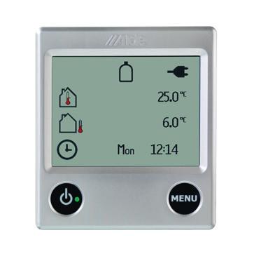
19 2. OPERATING INSTRUCTIONS FOR CONTROLPANEL CAUTION Do not drink any alcohol or take any drugs before or during operating the heating system and follow the safety instructions in this manual carefully. 2:1 TURNING THE BOILER ON AND OFF The heating system is switched off. The heating system is switched on High Efficiency 1. To start the boiler, press the On/Off button and the start-up display appears. The boiler starts with the last selected settings. A green LED comes on beside the On/Off button when the panel/heating system is on. 2. To switch off the boiler, press the On/ Off button. GB 2:2 STANDBY If Background light is set to Dark, the display goes out when it enters standby mode, but lights up if you press the screen. See settings in section 2:11, point 8. C B A D E F G H I L J K 22 C 6 C Fri M 2:3 SETTINGS MENU Launch the settings menu by pressing the MENU button. The background light comes on and those functions that can be set are displayed. Settings that you make are automatically saved after 10 seconds. The control panel will go to standby automatically after 30 seconds if the screen has not been touched. The control panel in standby mode. A. Clock. The clock shows the day and time (if activated). To set the clock, see under section 2:11 point 4. B. *Outdoor temperature. C. Indoor temperature. D. Circulation pump. The symbol is displayed when the pump is in operation. E. Automatic start of the boiler. The symbol is displayed when the function is activated in accordance with section 2:11 point 18. F. Day mode. The symbol is displayed when the function is on and turns green when activated The control panel in settings menu. G. *LPG bottle full/empty. The symbol is displayed when the sensor on DuoControl is connected and activated. If EisEX is installed a snowflake is shown inside the gas botle. Green bottle = Bottle full Red bottle = Bottle empty H. Night mode. The symbol is displayed when the function is on and turns green when activated. I. High altitude mode. The symbol flashes if the high altitude mode is activated. J. The symbol flashes during heat up of *Alde Flow (part no ) when set in more hot water mode. K. 230 volt. The symbol is displayed when 230 V is connected to the boiler. L. On/Off button. Main switch for boiler. M. MENU button. Button for settings menu. +22 C 22 C 6 C Fri kw ACC For activated functions, see section 2:9. For the tools menu, see section 2:10. Functions marked with a (*) are accessories, which are not installed on all vehicles, refer to the vehicle manufacturer s instructions
20 2:4 SET THE DESIRED TEMPERATURE The temperature can be set between +5 C and +30 C, inclusive, in increments of 0.5 C. +22 C 1. The temperature displayed is the temperature which is currently set. 2. Increase the temperature by pressing the + button. Reduce the temperature by pressing the - button. 3. The settings are now complete and the boiler will work at the set temperature. 1 kw ACC If night or day mode is activated (see section 2:11 point 1 and 2) and the time is within the scheduled period a moon or a sun will appear beside the temp setting. The temperature set will be the one of the mode shown below. +22 C +22 C Night mode Day mode 2:5 DOMESTIC HOT WATER The boiler is fitted with a built-in hot water boiler which can hold approximately 8.5 litres. The boiler can equally well be used without there being any freshwater in the boiler. There are three different settings for hot water: no hot water, normal operation and more hot water. +22 C 1 kw ACC 1. No hot water. If domestic hot water is not needed, press the - button (symbol becomes empty). If night,day or antimicrobial mode is activated (see section 2:11 point 1,2 and 14) and the time is within the scheduled period a moon,sun or the antimicrobial symbol will appear inside the hot water setting.the hot water setting will be the one of the mode shown below. Antimicrobial Night mode mode Day mode +22 C 2. Normal operation. If there is freshwater in the heater and hot water is required, press the + button (the symbol will then show half-shaded). 1 kw ACC If the pump operation function has been set to Cont., see section 2:11 point 17, this option cannot be selected. WARNING SCALDING HAZARD Since the hot water and the glycol heating fluid is heated simultaneously, the hot water can be very hot when a high level of heating is required C 1 kw ACC 3. More hot water. If you need more hot water, the water temperature can be temporarily increased to around 70 C. Press the + button so that the symbol shows fully shaded (black). The boiler returns to normal operation after 30 minutes. NB. If the pump operation function is set to Cont., see section 2:11 point 17, then the continuous pump operation function is turned off for 30 minutes, before then returning to continuous pump operation. NB. If an additional hot water tank (*Alde Flow part no ) is installed and the panel is in more hot water mode, the hot water function can then be in operation for longer than 30 minutes. Info! When hot water only is required, during the summer for instance, or when there is no requirement for hot water, no settings need to be made; the boiler looks after this function automatically. Functions marked with a (*) are accessories, which are not installed on all vehicles, refer to the vehicle manufacturer s instructions.
21 2:6 HEATING WITH ELECTRICITY Proceed as follows to activate heating with electricity. The more power (wattage) you select, the quicker heating will take. A priority can be set when selecting both electricity and gas, see section 2:11 point 3. The boiler uses no more power than is needed, even if it is set for 3kW. +22 C 1 kw ACC 1. Use the + or - button to switch on the electric heating and toggle between the various power modes (Off, 1 kw, 2 kw or 3 kw) The set value will be displayed on the screen. The activated mode is indicated by the + button changing colour to green. If a *load monitor is installed and set, the boiler will not use more electricity than it is capable of even if 3 kw is selected. 2. The settings are now complete and the boiler is working at the set temperature. 3. To switch off electrical operation, use the - button to toggle to Off. GB 2:7 HEATING WITH GAS Proceed as follows to activate heating with gas. A priority can be set when selecting both electricity and gas, see section 2:11 point C 1 kw ACC 1. Start gas operation by pressing the LPG flame symbol. The LPG symbol is activated and changes colour to green. 2. The settings are now complete and the boiler will work at the set temperature. 3. To switch off gas operation, press the LPG flame symbol. It will now change to blue. 2:8 *FULLY AUTOMATIC CLIMATE CONTROL (ACC) If a Truma AC is connected up to the Alde, then the ACC button is visible and it is possible to control ACC from the panel. This function makes it possible to have fully automated climate control for both heating, cooling and hot water. The button is grey if not installed or if 230 V is disconnected. With an outside temperature sensor (part no ) fitted, ACC function is improved: operation of the AC is modified in line with the outdoor temperature. Figure 1 Figure 2 Figure C +22 C +22 C 1 kw 1 kw 1 kw ACC ACC ACC 1. Set the desired temperature. 2. Press the blue ACC button, the button turns green (see fig. 2) and the ACC function is switched on, but is not necessarily in operation. If gas and/or electricity is switched on, AC and the boiler work to deliver the temperature set, regardless of whether heat or cooling is needed in the vehicle. To turn off the ACC function, press the ACC button and it becomes blue. NB. Temperature sensors that are used when fully automatic climate control is in operation must be positioned so that they are influenced equally by the heat from the Alde heating system and the air from the AC. In certain cases it can be an advantage to use Alde s temperature sensor (part no ). Functions marked with a (*) are accessories, which are not installed on all vehicles, refer to the vehicle manufacturer s instructions. 3. To turn AC lighting off and on, press the button rapidly. When the button is kept pressed in, the light changes from dark to light and then back (light to dark) and so on in 8 brightness levels. When the button is released it stays at the current brightness. This button is only visible when an AC* with in-built light is connected
22 2:9 ACTIVATED FUNCTIONS A Activated functions (see figure 2) can be accessed by pressing the A symbol (see figure 1). This screen shows the various functions that are activated. The respective function that is activated can be accessed from here and new settings can be made. The A symbol is only visible if one of the functions shown below is activated and/or installed. Figure 1 Figure C A Activated Functions 1 kw ACC Below is a description of the different symbols in the Activated Functions menu. For more detailed description, see section 2:11 Tools menu functions. Night mode is activated. However, it does not have to be within the time/day setting. * Load monitor is connected and set to limited current. Automatic start of the boiler is activated. However, it does not have to be within the time setting. * Booster is on. * This function is used if the heating system is to be operated via an external panel. High altitude mode is activated. * Displayed if one or two external room sensors are connected. * EisEx is installed but not necessarily turned on. Circulation pump in continuous operation. * DuoControl or DuoComfort is installed and connected to Alde Compact 3020 HE Day mode is activated. However, it does not have to be within the time/day setting. * Timer for engine heater is set but not necessarily within the set time/day. * The boiler is set to be started with External start but has not necessarily been activated. * Underfloor heating is in operation Functions marked with a (*) are accessories, which are not installed on all vehicles, refer to the vehicle manufacturer s instructions.
23 2:10 TOOLS MENU The tools menu can be accessed from the settings menu. +22 C 1. The control panel showing the settings menu. Press the tool symbol to access the tools menu GB 1 kw ACC 2:11 TOOLS MENU FUNCTIONS The following tools are available from the tools menu. A grey function button means the function has not been installed and/or activated in Installed Accessories, see section 2:15 Activation of installed functions Settings 1/4 Settings 2/4 Settings 3/4 Settings 4/ Night mode Automatically changes certain functions during the night. You can select whether this is to take place every night or a specific night each week. The functions that can be changed are: Temperature *Change to temperature sensor in sleeping accommodation area. Invert display Turn off the domestic hot water *AC in quiet mode 2. Day mode Automatically changes certain functions, e.g. if you are away for a while during the day. Select that it takes place every day or a specific day each week. The functions that can be changed during the day are: Temperature Turn off the domestic hot water 3. Prio setting With this function you can choose to priorities (select) electricity or gas as the main alternative. 4. Clock The clock must be set if engine heater start, night and/or day auto and automatic start are to work. If 12 V power is lost, the clock will stop and will no longer be displayed. Installing *battery backup (part no ) will prevent this happening. 5. Return To return to the previous menu, press this symbol. 6. *Setting room sensor Select which temperature sensor is to be active. Here you can select whether the sensor located in the daytime living area, the sleeping accommodation or in the panel is to be active. If Auto is selected, the sensor in the panel is active and will automatically switch to a room sensor (sofa and/or bed) if one of these is connected. If two room sensors are connected, it will be the one for the daytime living area that is active (sofa). Functions marked with a (*) are accessories, which are not installed on all vehicles, refer to the vehicle manufacturer s instructions
24 7. Arrow symbols Toggle between the various tool fields by using the up/down arrow symbols. Leave the tools menu using the MENU button or the return button. 8. Background light The background light can be set in three different modes, Dark, Bright and Invert. Dark: Turns off backgrund light. Press the screen or the menu button when standby is activated and the screen comes on, but returns to dark after 30 seconds if the panel is not touched. Bright: Background light in standby mode. Invert: Inverted background light in standby mode. Standby is activated automatically after 30 seconds if the panel is not touched. 9. *EisEX, 12 V defroster for gas regulator This is a small heating element that prevents ice forming in the regulator in winter (for Mono Control CS, DuoControl CS, DuoControl and DuoComfort). If DuoControl CS or DuoControl is installed and connected, a snowflake will appear inside the gas bottle symbol when EisEX is switched on. 10. *Load monitor The function prevents overload of the fuses on 230 V. If the total current consumption of the vehicle exceeds the set value, the electrical output of the boiler will be reduced automatically. This also applies to Truma Comfort AC if connected to the Alde Due to voltage fluctuations and tolerances, different regulation levels can be selected (5-17 A). If the fuse blows repeatedly, choose a lower setting. NB. For ACC to function with the load monitor, ACC must be on from the panel and not via the remote control. 11. *Booster Control of booster in two different speeds. Fan start and stop is controlled from the boiler. If the boiler s circulation pump starts up, the fan on the booster will as well. When the circulation pump stops, the fan will continue to run for another six minutes. It will then stop unless the circulation pump has started up again. 12. *Under floor heating The function governs the under floor heating pump s operation in intervals, which means that the under floor heating pump is in operation for 5 min and is then off for 5 min when heat is required. Mode: Make sure Delay or Cont. is activated; in these two modes, under floor heating is switched on. In Off mode under floor heating is off. NB. In Cont. mode it can get hotter in the vehicle than desired, as the heat control is disabled! Delay: The under floor heating pump is on for a certain period after the boiler s circulation pump has stopped, this Delay can be set at 15 min, 30 min or 120 min. 13. *Engine heater The function makes it possible to use the heating system to heat up the engine in a motor home, bus etc. Engine heater start: Press the button marked Off; the text will change to On and the button will turn green. Then set the required starting time and day. Engine heating starts at the set time and day. The engine heater then runs for 60 minutes before stopping automatically. NB. The clock in the panel must be set for the function to work. 14. Antimicrobial mode The boiler will start at in the morning (if the clock is set) and run as indicated for More hot water for 30 minutes (see section 2:5). This is to reduce the risk of legionella. 15. Offset (temperature adjustment) If the temperature that is displayed in the panel does not correspond to the actual temperature, it can be adjusted by ±5 C in the panel. Applies also to display of external temperature. 16. High altitude mode The function should only be used if the boiler will be powered by LPG at a height above 1000 m above sea level. NB. For LPG operation at high altitude, use propane to obtain stable combustion. NB. Variations in operating conditions at high altitudes can mean that the boiler always achieves stage 1 output, but not always stage 2 on LPG operation Functions marked with a (*) are accessories, which are not installed on all vehicles, refer to the vehicle manufacturer s instructions.
25 17. Circulation pump settings Cont. This function limits the supply of hot water, particularly when there is a low heating requirement. Therm: The pump is controlled by the room sensor. This is the normal mode for heat and hot water. 18. Automatic boiler start Starting the boiler at a certain time/on a certain day. The boiler will be on every week during the time set, until the function is deactivated. For automatic start to function, the boiler must be turned off. 19. Sound Audible signals in various situations: Turn the button sound on and off. Audible signal on reaching hot water temperature when Alde Flow* is installed and more hot water is selected. Audible signal on Gas Failure. Audible signal on LPG bottle change over if a DuoControl* is installed and activated in Installed Accessories, see section 2: Reset Pressing Reset resets the panel to its factory settings. NB. Settings made in installed functions are not deleted. 21. External start The function is used when starting the boiler from outside. When external start has been activated the panel must be turned off. External start has three modes, Off, Ext and 230 V. 22. Language Switch between different languages. Available languages are English, French and German. However, the service menu is only available in English, see section 2: Installed functions The accessories that are installed are activated here, see section 2: Service menu This contains the following, amongst others: Glycol temperature Domestic hot water temperature 12 V power to the boiler To exit the tools menu, press Return or Menu. GB Off. The function is turned off. *Ext. The function is used when starting the boiler through an external signal. When the Ext. function has been activated, the control panel must be turned off, but 12 V should be connected. The parameters/functions that the boiler is to have when it starts must be set before turning off the control panel. NB. Using this function requires installation of an accessory that can use external start. 230 V. The function is used to start the boiler by connecting 230 V to the vehicle. When the 230 V function has been activated the control panel must be turned off, but 12 V should be connected. The parameters/functions that the boiler is to have when it starts must be set before turning off the control panel (230 V connected). Certain vehicles can be equipped with an individual solution (*winter connection). Functions marked with a (*) are accessories, which are not installed on all vehicles, refer to the vehicle manufacturer s instructions
26 2:12 SERVICE MENU The Service menu is accessed by pressing Service (see fig. 1). The function shows the values from the boiler on the screen (fig. 2 to 4). The values are updated every second. Figure 1 Settings 4/4 Figure 2 Figure 3 Figure 4 1/3 Service 2/3 Service 3/3 Service Glycol Temp: 80 C Water Temp: 55 C Fan rotation: 0RPM Current: 0.0A Overheat: Deact PCB Temp: Ext Switch: Boiler: Panel: 12VBat: 20 C deact XXXX XXXX XXXX AC: inetbox: XXXX XXXX Functions marked with a (*) are accessories, which are not installed on all vehicles, refer to the vehicle manufacturer s instructions.

27 2:13 ERROR MESSAGES Low battery: If the vehicle has a battery voltage of less than 10.8 V, the boiler will stop. This is reset automatically once the voltage reaches 11 V. If the voltage becomes lower, various error messages may also occur. These are not genuine faults. Ensure that the boiler has the right voltage. Fan restarts: Incorrect fan speed. New start attempt is made. Repeated faults results in Fan failure. If Fan failure recurs after resetting, contact a dealer. If Fan restarts is displayed, no action is necessary. Gas failure: The boiler has not managed to ignite the LPG flame. Ensure that gas is available. Overheat red fail: Overheat protection (red cable) tripped. This fault can arise if the boiler is run at high power at the same time as there are air pockets in the heating system, the heating system should then be bled properly. If the fault remains, contact a dealer. Also check that the fluid level in the expansion tank is at least 1 cm above the min line when cool. Overheat blue fail: Overheat protection (blue cable) tripped. Overheat PCB: The boiler s circuit board has overheat protection. If this gets too hot, the protection is tripped. Allow the boiler to cool down before resetting. * Window open: A window is open and the boiler stops running on gas. Gas operation of the boiler will restart once the window is closed. Electrical operation continues to function. Heater not found: There is a connection fault between the boiler and the control panel. Most probably a problem with the heater s circuit board. 3rd Part Panel C. fail: Communication fault between Alde s panel and Alde Smart Control*. Panel failure: Fault on the panel. May be caused by excessive moisture. No match Heater/Panel: The circuit board in the boiler is not intended for the Alde Compact 3020 HE and will not work with the 3020 HE panel. Red connection fail: Problem with the red cable or red ports. There is no communication with the 3020 heater, AC or inet. GB inet connection fail: Cannot find the inet box. Probably a problem with inet. In the event of inet connection fail, this button is displayed. Pressing the button will remove the error. Yellow connection fail: Problem with the cable between the Alde panel and the CI master panel or its ports. To reset some of the errors and restart, switch off the boiler from the panel, disconnect 230 V to the vehicle and disconnect 12 V from the boiler. 2:14 RESETTING Pressing Reset resets the panel to its factory settings. After resetting, the panel will be set as follows: Boiler Off mode; electrical operation 1 kw; LPG heating On mode; indoor temperature 22 C. Other functions are switched off. Settings 4/4 The functions that are checked under Installed functions (see section 2:15) will not be affected by a reset. A reset will also cancel error messages in the error log. Functions marked with a (*) are accessories, which are not installed on all vehicles, refer to the vehicle manufacturer s instructions
28 2:15 ACTIVATION OF INSTALLED FUNCTIONS The first time you use the heating system, check that the right accessories/functions are activated. This also applies when you supplement the heating system with accessories/functions. Activate accessories/functions by pressing on Installed Accessories, (see figure 1) and checking the box of the respective function/accessory to activate (see figure 2 to 5). Figure 1 Settings 4/4 Figure 2 Figure 3 Figure 4 Figure 5 Inst Acc 1/4 Inst Acc 2/4 Inst Acc 3/4 Inst Acc 4/4 Third party Panel Main Manual 12V Booster Underfloor Heating Pump Load Monitor Main Remot 12V Duo Control Alde Flow EisEx Engine Pre-Heat Pump The relevant box must be checked if you have: Connected an external panel or Alde Smart Control (part no ). Connected a gas bottle changer (DuoComfort or DuoControl). Connected a load monitor. Connected a defroster (EisEx). Connected a 12 V pump that can be variably adjusted manually. Connected a 12 V pump to the under floor heating. Connected a PWM controlled 12 V pump that has variable speed control and is set from the panel. Connected a booster. Connected an additional hot water tank to increase the hot water capacity and also obtain continuous hot water (part no ). Connected a 12 V pump for heating the vehicle s engine through the Alde heating system Functions marked with a (*) are accessories, which are not installed on all vehicles, refer to the vehicle manufacturer s instructions.

29 2:16 CABLE CONNECTION COMPACT 3020 HE AND CONTROL PANEL 3020 Connect accessories to the boiler and control panel as shown in the diagram below. Do not clamp or bind 12 V cables or sensor cables together with 230 V cables. It is preferable not to place the cables close to each other. If the cables are bundled, there is a greater risk of malfunction during operation. GB Backside of control panel 3020 Circuit board on Compact 3020 HE boiler Load monitor E Outdoor sensor F Tin bus Control panel Remote Sensor 2 Remote Sensor 1 Battery Back-up (3V DC) + Bed Sofa 12 V DC Fuse 3,15 A 12 V D pump External start I Window sensor Option board/ Mechanical panel External panel CI Bus Heater *Truma AC and inet Box are connected to the TIN Bus port. 12 V DC FUSE 3,15 A ALDE FLOW EIS EX HEATER *The automatic climate control functions with: - Truma Aventa comfort - Truma Aventa eco - Truma Saphir comfort RC - Saphir compact (serial no. > ) Saphir compact needs a Truma adapter OUT 12V DC CONNECTED TO HEATER - + Optional board for Compact 3020 HE Mechanical panel To protect against malfunction only use original Alde cables, shielded cable for EMC. Functions marked with a (*) are accessories, which are not installed on all vehicles, refer to the vehicle manufacturer s instructions
Residential Gas Condensing Boiler Greenstar ZBR16/21/28/35/42-3A... ZWB28/35/42-3A...
 70 80 99-00-O Residential Gas Condensing Boiler ZBR//8/35/4-3A... ZWB8/35/4-3A... 70 80 993 (03/03) CA/US Operating Instructions Contents Contents Key to symbols and safety instructions............................
FITTED EQUIPMENT FITTED EQUIPMENT
 Truma Combination Boiler... 94 Truma heating system and air flow... 95 Truma CP 25 digital timer control... 95 Truma CP Plus digital timer control... 99 Truma Combination Boiler fault finding... 107 Truma
/2010 US/CA
 6 720 646 148-11/2010 US/CA (en) For the user User s Instructions Condensing gas boiler Logamax plus GB162-L.B. 80 kw/100 kw Please read thoroughly before operating This manual is available in the English
Operating instructions
 The energy you need Operating instructions Betacom 3 24c -A (H-GB) 30c -A (H-GB) GB, IE Contents Contents 1 Safety... 3 1.1 Action-related warnings... 3 1.2 Intended use... 3 1.3 General safety information...
Residential Gas Condensing Boiler Greenstar combi 100 p / 151 p ZWB28-3A... ZWB42-3A...
 Residential Gas Condensing Boiler Greenstar combi 00 p / 5 p ZWB8-3A... ZWB4-3A... Operating Instructions 708733 (07/04) US/CA Contents Contents Explanation of symbols and safety instructions.......................
Operating instructions
 Operating instructions Capriz 2 24c 28c GB, IE Contents Contents 1 Safety... 3 1.1 Action-related warnings... 3 1.2 Intended use... 3 1.3 General safety information... 4 2 Notes on the documentation...
USER'S INFORMATION MANUAL
 USER'S INFORMATION MANUAL : If the information in this manual is not followed exactly, a fire or explosion may result causing property damage, personal injury or loss of life. Do not store or use gasoline
Residential Gas Hybrid Water Heater
 Residential Gas Hybrid Water Heater USER S INFORMATION MANUAL WGRGH20NG75F / WGRGH20NG76F / WGRGH20NG100F WGRGHNG75F / WGRGHNG76F / WGRGHNG100F Models* *A suffix of LP denotes propane gas NOTICE: Westinghouse
Operating instructions
 Operating instructions Gas condensing boiler WARNING: If the information in this manual is not followed exactly, a fire or explosion may result causing property damage, personal injury or loss of life.
User s Information Manual
 User s Information Manual Gas-Fired Water Boilers With or without Aqua Logic (CWH) Now available Matching High Performance Companion Water Heater (Unit sold separately) If the information in this manual
Fully-automatic Gas tankless Water Heater USER'S MANUAL FOR MODEL EZ-101 ISO9001 certified
 Fully-automatic Gas tankless Water Heater USER'S MANUAL FOR MODEL EZ-101 ISO9001 certified Thank you for purchasing our fully-automatic gas-fired tankless water heater. Please completely read this Manual
Universal Fire Tube Boiler Wall Mount Models
 Universal Fire Tube Boiler Wall Mount Models USER S INFORMATION MANUAL Models WBRU**80W / 100W / 120W / 140W / 175W / 199W **NG denotes Natural Gas Model, LP Denotes Propane Model Heat Exchanger Bears
Aqua Balance. User s Information Manual. WMB-155C Wall Mount Gas-Fired Combination Boiler Heating and Domestic Hot Water
 Aqua Balance WMB-155C Wall Mount Gas-Fired Combination Boiler Heating and Domestic Hot Water User s Information Manual * Low Lead Content If the information in this manual is not followed exactly, a fire
GB24 & GB30. User Manual
 GB24 & GB30 User Manual BOILER OUTPUT To Domestic Hot Water:To Central Heating: GB24/30 Minimum 8.0 kw (27,296 Btu/h) GB24 Maximum 24.2 kw (82,570 Btu/h) GB30 Maximum 30.3 kw (103,384 Btu/h) GB24/30 Minimum
Operating instructions
 Operating instructions For the operator Operating instructions ecotec plus Gas-fired wall-hung high-efficiency boiler GB, IE Publisher/manufacturer Vaillant GmbH Berghauser Str. 40 D-42859 Remscheid Telefon
User s Information Manual
 User s Information Manual CONDENSING GAS BOILER 220/299/300/399 If the information in this manual is not followed exactly, a fire or explosion may result, causing property damage, personal injury or loss
Tankless Water Heater
 Tankless Water Heater USER S INFORMATION MANUAL Models WGRT**150 / WGRT**199 / WGRTC**199 **A suffix of LP denotes propane gas **A suffix of NG denotes natural gas NOTICE: Westinghouse reserves the right
Gas Fired Residential Combi Boiler Floor and Wall Mount Models
 Gas Fired Residential Combi Boiler Floor and Wall Mount Models USER S INFORMATION MANUAL Models WBRC**140W WBRC**199W WBRC**140F WBRC**199F ** NG Refers to Natural Gas Operation LP Refers to Propane Gas
User s Information Manual
 User s Information Manual Gas-Fired Storage Water Heater, Tankless Water Heater, Heating Appliance, and Combination Appliance Models IF THE INFORMATION IN THIS MANUAL IS NOT FOLLOWED EXACTLY, A FIRE OR
Logic+ Combi
 USER GUIDE Logic+ Combi 24 30 35 When replacing any part on this appliance, use only spare parts that you can be assured conform to the safety and performance specification that we require. Do not use
USER GUIDE VOGUE COMBI GEN2 C26 C32 C40
 USER GUIDE VOGUE COMBI GEN2 C26 C32 C40 When replacing any part on this appliance, use only spare parts that you can be assured conform to the safety and performance specification that we require. Do not
Owner s Manual AIR TO WATER HEAT PUMP. Hydro Unit HWS-804XWHM3-E HWS-804XWHT6-E HWS-804XWHT9-E HWS-1404XWHM3-E HWS-1404XWHT6-E HWS-1404XWHT9-E
 AIR TO WATER HEAT PUMP Hydro Unit Model name: HWS-804XWHM3-E HWS-804XWHT6-E HWS-804XWHT9-E HWS-1404XWHM3-E HWS-1404XWHT6-E HWS-1404XWHT9-E English Thank you very much for purchasing TOSHIBA Air to Water
Operating instructions
 Operating instructions For the operator Operating instructions HOME SYSTEM GB, IE Publisher/manufacturer Vaillant GmbH Berghauser Str. 40 D-42859 Remscheid Tel. +49 21 91 18 0 Fax +49 21 91 18 28 10 info@vaillant.de
Owner's Manual TABLE OF CONTENTS
 40MAQ High Wall Ductless System Sizes 09 to 36 Owner's Manual TABLE OF CONTENTS PAGE A NOTE ABOUT SAFETY... 2 GENERAL... 2 PART NAMES... 3 FUNCTION BUTTONS... 4 DISPLAY PANELS... 5 REMOTE CONTROL... 6
OPERATION MANUAL. Daikin Altherma indoor unit EKHVMRD50ABV1 EKHVMRD80ABV1 EKHVMYD50ABV1 EKHVMYD80ABV1
 OPERATION MANUAL EKHVMRD50ABV1 EKHVMRD80ABV1 EKHVMYD50ABV1 EKHVMYD80ABV1 EKHVMRD50+80ABV1 EKHVMYD50+80ABV1 CONTENTS Page 1. Definitions... 1 2. Introduction... 2 2.1. General information... 2 2.2. Scope
USER GUIDE VOGUE MAX SYSTEM
 USER GUIDE VOGUE MAX SYSTEM 15 18 26 32 When replacing any part on this appliance, use only spare parts that you can be assured conform to the safety and performance specification that we require. Do not
User s Information Manual
 User s Information Manual Series 2 Models 1000-2000 MBH Commercial Condensing Gas-fired water boilers If the information in this manual is not followed exactly, a fire or explosion may result, causing
User s Information Manual
 User s Information Manual Model NPE-24AWE NPE-24SWE NPE-32AWE NPE-32SWE Condensing Water Heater These appliances are for use with natural gas or LPG. (An LPG conversion kit is included with the water heater.)
User s Information Manual
 Gas-fired Water boiler Series 2 NOTICE: Series 1/Series 2 identification Read the boiler rating plate to determine the series number. The rating plate is located on the right side of the boiler. User s
OWNER S MANUAL DLFCAB / DLFCHB / DLFDAB / DLFDHB High Wall Ductless System Sizes 09 36
 OWNER S MANUAL DLFCAB / DLFCHB / DLFDAB / DLFDHB High Wall Ductless System Sizes 09 36 TABLE OF CONTENTS PAGE SAFETY PRECAUTIONS... 2 GENERAL... 2 INDOOR UNIT PART NAMES... 3 REMOTE CONTROL PART NAMES...
DEHUMIDIFIER OWNER S MANUAL. Read this manual carefully before operating the appliance and retain it for future reference.
 OWNER S MANUAL DEHUMIDIFIER ESPAÑOL FRANÇAIS Read this manual carefully before operating the appliance and retain it for future reference. Model : UD701KOG1 P/NO : MFL68026017 www.lg.com TABLE OF CONTENTS
USER'S INFORMATION MANUAL
 USER'S INFORMATION MANUAL WARNING: If the information in this manual is not followed exactly, a fire or explosion may result causing property damage, personal injury or loss of life. Do not store or use
G61MPV SERIES GAS FURNACE WARNING
 2003 Lennox Industries Inc. Dallas, Texas, USA 504,809M 03/2009 Supersedes 06/2003 G61MPV SERIES GAS FURNACE Litho U.S.A. FIRE OR EXPLOSION HAZARD. Failure to follow safety warnings exactly could result
OPERATING MANUAL AIR CONDITIONER DUCT TYPE. ART Series KEEP THIS MANUAL FOR FUTURE REFERENCE FUJITSU GENERAL LIMITED P/N
 OPERATING MANUAL AIR CONDITIONER DUCT TYPE ART Series KEEP THIS MANUAL FOR FUTURE REFERENCE FUJITSU GENERAL LIMITED P/N9374379293-02 CONTENTS SAFETY PRECAUTIONS... 1 NAME OF PARTS... 2 PREPARATORY OPERATION...
INSTRUCTION FOR THE USER THC V E OIL BLU
 INSTRUCTION FOR THE THC V E OIL BLU CONTENTS General safety information 4 Precautions 4 Control panel 5 Mode selection 8 User levels 10 Start-up 12 Temporary shutdown 15 Preparing for extended periods
USER S INFORMATION MANUAL
 2017 Lennox Industries Inc. Dallas, Texas, USA 506737-01 04/2017 Supersedes 03/2017 USER S INFORMATION MANUAL EL195UHE SERIES GAS FURNACE Improper installation, adjustment, alteration, service or maintenance
OWNER S MANUAL HIGH WALL INVERTER. (English) (BSHVD1S SERIES)
 (BSHVD1S SERIES)") OWNER S MANUAL HIGH WALL INVERTER (English) (BSHVD1S SERIES) IMPORTANT As with any product that has moving parts or is subject to wear and tear, it is VERY IMPORTANT that you maintain your air conditioner
OWNER S MANUAL HIGH WALL INVERTER (English) (BSHVD1S SERIES) IMPORTANT As with any product that has moving parts or is subject to wear and tear, it is VERY IMPORTANT that you maintain your air conditioner
Operating Instructions
 Operating Instructions Low Emissions and High Efficiency Condensing Oil Boiler DANGER! If these instructions are not followed exactly, a fire or explosion may be caused with serious property damage or
OWNER'S MANUAL R-410A Duct Free Split System Air Conditioner and Heat Pump
 R-10A Duct Free Split System Air Conditioner and Heat Pump Product Family: DFF(A/H)H, DFC(A/H) Please read the operating instructions and safety precautions carefully and thoroughly before installing and
OWNER S MANUAL. R 410A Ductless Split System Air Conditioner and Heat Pump
 R 410A Ductless Split System Air Conditioner and Heat Pump Models DLC4(A/H) Outdoor Unit, DLF4(A/H) Indoor Unit Sizes 9K, 12K, 18K, 24K, 30K and 36K Please read the operating instructions and safety precautions
EL195DFE SERIES GAS FURNACE WARNING
 2011 Lennox Industries Inc. Dallas, Texas, USA 506739 01 06/2011 EL195DFE SERIES GAS FURNACE Litho U.S.A. FIRE OR EXPLOSION HAZARD. Failure to follow safety warnings exactly could result in serious injury,
Bosch 80% AFUE Gas Furnace BGS80 Model
 Bosch 80% AFUE Gas Furnace BGS80 Model 4-Way Multipoise Category I Fan-Assisted Furnace User's Information Manual 3124627 2 Bosch 80% AFUE Gas Furnace User's Information Manual Data subject to change 06.2018
CASSETTE TYPE. AUT Series FUJITSU GENERAL LIMITED AIR CONDITIONER OPERATING MANUAL P/N KEEP THIS MANUAL FOR FUTURE REFERENCE AM PM
 OPERATING MANUAL AIR CONDITIONER CASTE TYPE AUT Series AM PM 6 9 5 8 KEEP THIS MANUAL FOR FUTURE REFERENCE FUJITSU GENERAL LIMITED P/N9704 CONTENTS SAFETY PRECAUTIONS... NAME OF PARTS... PREPARATORY OPERATION...
USER'S INFORMATION MANUAL
 USER'S INFORMATION MANUAL WARNING: If the information in this manual is not followed exactly, a fire or explosion may result causing property damage, personal injury or loss of life. Do not store or use
Mikrofill Ethos Condensing combination boiler
 Mikrofill Ethos Condensing combination boiler User Instructions 24cc CE Mark Mikrofill gas appliances comply with the requirements contained in CE Mark documents contained with European directives applicable
ELECTRIC BOILERS FOR CENTRAL HEATING
 ELECTRIC BOILERS FOR CENTRAL HEATING TermoMax INSTRUCTIONS FOR INSTALLATION INSTRUCTIONS FOR INSTALLATION We reserve the right of alternations WE ARE NOT LIABLE FOR DAMAGES RESULTING FROM NON- OBSERVING
USERS GUIDE. LOGIC+ Combi 24, 30, 35
 USERS GUIDE LOGIC+ Combi 24, 30, 35 When replacing any part on this appliance, use only spare parts that you can be assured conform to the safety and performance specification that we require. Do not use
User Manual FLOWMAX-90. for model. Condensing water heater 85,000 BTU. Installation, operating, commissioning and maintenance instructions.
 User Manual for model FLOWMAX-90 Condensing water heater 85,000 BTU WARNING If the information in these instructions is not followed exactly, a fire or explosion may result, causing property damage, personal
P.O. Box , Dallas, TX USER'S INFORMATION MANUAL Single-Stage Warm Air Gas Furnaces
 P.O. Box 799900, Dallas, TX 75379-9900 USER'S INFORMATION MANUAL Single-Stage Warm Air Gas Furnaces This is a safety alert symbol and should never be ignored. When you see this symbol on labels or in manuals,
Combi 2 E / 4 E CP plus (Australia) Operating instructions Page 2. To be kept in the vehicle!
 Operating instructions Page 2. To be kept in the vehicle!") Combi 2 E / 4 E CP plus (Australia) Operating instructions Page 2 To be kept in the vehicle! Combi 2 E / 4 E CP plus (Australia) 4 5 1 2 6 10 13 15 16 12 8 10 14 6 1 Control panel (digital) 2 Room temperature
Combi 2 E / 4 E CP plus (Australia) Operating instructions Page 2 To be kept in the vehicle! Combi 2 E / 4 E CP plus (Australia) 4 5 1 2 6 10 13 15 16 12 8 10 14 6 1 Control panel (digital) 2 Room temperature
Truma AquaGo LP Gas Instant Water Heater
 Truma AquaGo LP Gas Instant Water Heater Model: Truma AquaGo basic (DLE6AB) * Truma AquaGo comfort (DLE6AC) * Truma AquaGo comfort plus (DLE6ACP) * * Patent Pending Operating instructions Page 2 Installation
Operating instructions
 Operating instructions Gas-fired condensing boiler Logano plus GB312 For the user Please read carefully before use 7 747 009 296-01/2007 EN Contents 1 For your safety..............................................
User s Information Manual
 User s Information Manual Gas-fired water boilers Series 4 Featuring Flexibility Series 4 If the information in this manual is not followed exactly, a fire or explosion may result, causing property damage,
OPERATING MANUAL UTY-RNNYM P/N English
 OPERATING MANUAL English UTY-RNNYM P/N9373329206-04 OPERATING MANUAL CONTENTS SAFETY PRECAUTIONS... 1 NAME OF PARTS... 2 PREPARATORY OPERATION... 3 OPERATION... 4 TIMER FUNCTIONS... 6 ON/OFF TIMER... 6
USER S INFORMATION MANUAL
 USER S INFORMATION MANUAL UPFLOW & DOWNFLOW/HORIZONTAL CONDENSING GAS FURNACES SAFETY Recognize this symbol as an indication of Important Safety Information If not installed, operated and maintained in
EL195UH SERIES GAS FURNACE WARNING
 2010 Lennox Industries Inc. Dallas, Texas, USA 506597 01 11/2010 EL195UH SERIES GAS FURNACE Litho U.S.A. FIRE OR EXPLOSION HAZARD. Failure to follow safety warnings exactly could result in serious injury,
USER'S INFORMATION MANUAL
 USER'S INFORMATION MANUAL WARNING: If the information in this manual is not followed exactly, a fire or explosion may result causing property damage, personal injury or loss of life. Do not store or use
USER'S INFORMATION MANUAL
 USER'S INFORMATION MANUAL WARNING: If the information in this manual is not followed exactly, a fire or explosion may result causing property damage, personal injury or loss of life. Do not store or use
i 24, i 30, i 35 combination boilers USER GUIDE For Installation Guide see reverse of book UIN A05 October 2017
 24 1 2 23 3 4 5 20 6 I 19 7 18 8 9 15 14 11 13 12 i 24, i 30, i 35 combination boilers USER GUIDE For Installation Guide see reverse of book i 24 OFF MAX E STATUS BURNER RESET MIN PRE MIN MAX HEAT PREHEAT
EL195UHE SERIES GAS FURNACE WARNING WARNING
 2012 Lennox Industries Inc. Dallas, Texas, USA 506737-01 12/2012 Supersedes 06/2011 EL195UHE SERIES GAS FURNACE Improper installation, adjustment, alteration, service or maintenance can cause property
HEAT & COOL MODEL (REVERSE CYCLE)
") OPERATING MANUAL HEAT & COOL MODEL (REVERSE CYCLE) AIR CONDITIONER Duct Type Indoor Unit ARTG09LL ARTG12LL ARTG18LL KEEP THIS MANUAL FOR FUTURE REFERENCE P/N9374379439 CONTENTS SAFETY PRECAUTIONS... 1
OPERATING MANUAL HEAT & COOL MODEL (REVERSE CYCLE) AIR CONDITIONER Duct Type Indoor Unit ARTG09LL ARTG12LL ARTG18LL KEEP THIS MANUAL FOR FUTURE REFERENCE P/N9374379439 CONTENTS SAFETY PRECAUTIONS... 1
O. Gas boiler. Gaz 6000 W WBN H-E-N/L-S2400. Operating instructions for the end customer (2017/09) en
 en") 8 716 473 216-00.3O Gas boiler WBN 6000-30-H-E-N/L-S2400 Operating instructions for the end customer en 2 Contents Contents 1 Key to symbols and safety instructions................... 2 1.1 Key to symbols..................................
8 716 473 216-00.3O Gas boiler WBN 6000-30-H-E-N/L-S2400 Operating instructions for the end customer en 2 Contents Contents 1 Key to symbols and safety instructions................... 2 1.1 Key to symbols..................................
SLP98UH SERIES VARIABLE CAPACITY GAS FURNACE WARNING WARNING
 2015 Lennox Industries Inc. Dallas, Texas, USA 506443-01 01/2015 Supersedes 08/2012 SLP98UH SERIES VARIABLE CAPACITY GAS FURNACE Improper installation, adjustment, alteration, service or maintenance can
WHAT TO DO IF YOU SMELL GAS
 AHE AHE SERIES 4 Direct Vent Wall-Mounted Boilers User s Information Manual If the information in this manual is not followed exactly, a fire or explosion may result, causing property damage, personal
OWNER S MANUAL. High-Wall Fan Coil Unit CONTENTS
 OWNER S MANUAL High-Wall Fan Coil Unit Page GENERAL 2,3 OPERATING MODES 2 REMOTE CONTROL 2 OPERATION 3-9 REMOTE CONTROL OPERATION 3 INDOOR UNIT DISPLAY 5 EMERGENCY OPERATION 5 PRESSING THE ON/OFF BUTTON
CONTENTS SAFETY PRECAUTIONS. En-1 DANGER! CAUTION!
 CONTENTS SAFETY PRECAUTIONS... 1 NAME OF PARTS... 2 PREPARATORY OPERATION... 3 OPERATION... 3 TIMER FUNCTIONS... 5 ON/OFF TIMER... 5 WEEKLY TIMER... 6 TEMPERATURE SET BACK TIMER... 8 FILTER DISPLAY RESET...
Truma AquaGo LP Gas Instant Water Heater
 Truma AquaGo LP Gas Instant Water Heater Model: Truma AquaGo basic (DLE60B) * Truma AquaGo comfort (DLE60C) * * Patent Pending Truma AquaGo comfort plus (DLE60CP) * If the information in these instructions
User s Information Manual
 User s Information Manual Series 3 Models 550 and 750 MBH Commercial Condensing Gas-fired water boilers If the information in this manual is not followed exactly, a fire or explosion may result, causing
User Manual for model
 User Manual for model RKA 24/8 RKA 24 RKA 28 RKA 34 Wall mounted storage combi boiler premix condensing boiler User instruction CE 0694 RKA 24.8_24_28_34 - RAD - ING - MAN.UT - 1104A - DIGITECH 2 - REGNO
For the owner. Operating manual. ecotec plus 937. Gas condensing storage combination boiler VUI
 For the owner Operating manual ecotec plus 937 Gas condensing storage combination boiler GB VUI Contents Appliance characteristics Recommended accessories Contents Appliance characteristics... Recommended
EL296UHV SERIES GAS FURNACE WARNING WARNING
 2011 Lennox Industries Inc. Dallas, Texas, USA 506769 01 08/2012 Supersedes 10/2011 EL296UHV SERIES GAS FURNACE Improper installation, adjustment, alteration, service or maintenance can cause property
VIESMANN. Operating instructions VITODENS VITOPEND. for the system user. Heating system with Vitotronic 100 control unit for constant temperature mode
 Operating instructions for the system user VIESMANN Heating system with Vitotronic 100 control unit for constant temperature mode VITODENS VITOPEND 4/2007 Please keep safe. Safety instructions For your
USER S INFORMATION MANUAL Model: HSE 125 N/P, HSE 145 N/P Gas-fired, Condensing Boiler and Instantaneous Water Heater
 USER S INFORMATION MANUAL Model: HSE 125 N/P, HSE 145 N/P Gas-fired, Condensing Boiler and Instantaneous Water Heater Contents Section Page Major Components... 2 1 About Our Manual... 2 2 Refractory Handling...
Alde Heating System Safe, economical and friendlier to the environment
 Alde Heating System Safe, economical and friendlier to the environment (All options may not be fitted as standard) Control panel with touch screen All settings for the heating system are made on the control
User s Information Manual
 TM User s Information Manual Commercial Condensing Gas-fired water boilers If the information in this manual is not followed exactly, a fire or explosion may result, causing property damage, personal injury
User s Information Manual
 Condensing Combi Boiler User s Information Manual These appliances are for use with natural gas or LPG. (An LPG conversion kit is included with the boiler.) Type: B23-B33-B53-C13-C33-C43-C53-C63-C83 Gas
Elite. User s Information Manual. Elite and Elite VWH* All Models
 Elite User s Information Manual Elite and Elite VWH* All Models Heat Exchanger Bears the ASME H Stamp IF THE INFORMATION IN THIS MANUAL IS NOT FOLLOWED EXACTLY, A FIRE OR EXPLOSION MAY RESULT, CAUSING
Diplomat Inverter/Diplomat Duo Inverter
 www.thermia.com The English language is used for the original instructions. Other languages are a translation of the original instructions. (Directive 2006/42/EC) Copyright Thermia Värmepumpar Table of
DUCTED AIR CONDITIONER. Owner s Manual. KD Series KD24. Kaden Owner s Manual 1
 DUCTED AIR CONDITIONER Owner s Manual KD Series KD24 Kaden Owner s Manual 1 Table of Contents 1. Safety Precautions 4 2. Indoor Unit Parts and Major Functions 6 3. Care and Maintenance 8 4. Troubleshooting
FITTED EQUIPMENT FITTED EQUIPMENT
 ALDE Compact 3010... 98 ALDE Compact 3010 Control Panel... 103 Dometic absorption refrigerators... 111 Cooker 3 burner and hotplate... 132 Microwave oven... 137 Thetford C260 cassette toilet... 140 Caravans
USER S INFORMATION MANUAL
 USER S INFORMATION MANUAL UPFLOW/HORIZONTAL & DOWNFLOW TWO STAGE INDUCED DRAFT GAS FURNACES Recognize this symbol as an indication of Important Safety Information If the information in this manual is not
User Manual for model RK 18 RK 25 RK 34 CE 0694 RK 18_25_34 - RAD - ING - MAN.UT A - DIGITECH 2 - REGNO UNITO - EXTRAHEAT - CBD
 User Manual for model RK 18 RK 25 RK 34 Premix condensing boiler User instruction CE 0694 RK 18_25_34 - RAD - ING - MAN.UT - 1104A - DIGITECH 2 - REGNO UNITO - EXTRAHEAT - CBD Technical specification by
Cast Iron Commercial Hot Water Or Steam Boiler
 Cast Iron Commercial Hot Water Or Steam Boiler Users Information Manual UTICA BOILERS PO Box 4729 Utica, NY 13504-4729 www.uticaboilers.com An ISO 9001-2000 Certified Company P/N# 240006925U, Rev. 1.0
OPERATING INSTRUCTIONS AND OWNER S MANUAL
 OPERATING INSTRUCTIONS AND OWNER S MANUAL MR. HEATER READ INSTRUCTIONS CAREFULLY: Read and follow all instructions. Place instructions in a safe place for future reference. Do not allow anyone who has
User Manual RBS 24. for model CE series ENERGY. Wall mounted instantaneous combi boiler room sealed chamber
 User Manual for model RBS 24 series ENERGY Wall mounted instantaneous combi boiler room sealed chamber CE 0694 RBS 24 - SERIE ENERGY - RAD - ING - MAN.UT - 1407.1 - DIGITECH TR - MIAH6 - E04 Technical
Good Ideas For Propane Safety
 Good Ideas For Propane Safety What You Don't Know CAN Hurt You Safety...It's Up to You Propane is a safe, reliable fuel. Like many other fuels, however, it is flammable. That means it can be dangerous
Model No: Little Devil II (inc ss)
") GAS HEATER Model No: Little Devil II (inc ss) PART NO: 6926020, 6926025 (SS) OPERATION & MAINTENANCE INSTRUCTIONS LS1213 INTRODUCTION Thank you for purchasing this CLARKE Gas Heater. Before attempting
GAS HEATER Model No: Little Devil II (inc ss) PART NO: 6926020, 6926025 (SS) OPERATION & MAINTENANCE INSTRUCTIONS LS1213 INTRODUCTION Thank you for purchasing this CLARKE Gas Heater. Before attempting
OPERATING MANUAL. AIR CONDITIONER Duct Type. Indoor Unit ARTG36LH ARTG45LH ARTG54LH ARTG60LH PART NO KEEP THIS MANUAL FOR FUTURE REFERENCE
 OPERATING MANUAL AIR CONDITIONER Duct Type Indoor Unit ARTG36LH ARTG45LH ARTG54LH ARTG60LH KEEP THIS MANUAL FOR FUTURE REFERENCE PART NO. 9374379583 CONTENTS SAFETY PRECAUTIONS... 2 FEATURES AND FUNCTIONS...
Owner's Manual TABLE OF CONTENTS
 40MB*D Ducted Style Ductless System Sizes 09 to 48 Owner's Manual TABLE OF CONTENTS PAGE A NOTE ABOUT SAFETY... 2 GENERAL... 2 PARTS LIST... 3 DISPLAY PANELS... 4 FUNCTION BUTTONS... 5 REMOTE CONTROL...
USER S INFORMATION MANUAL
 USER S INFORMATION MANUAL UPFLOW, DOWNFLOW, UPFLOW/HORIZONTAL & HORIZONTAL ONLY INDUCED DRAFT GAS FURNACES Recognize this symbol as an indication of Important Safety Information If the information in this
ecotec pro Operating instructions Operating instructions For the operator GB, IE Gas-fired wall-hung high-efficiency boiler
 Operating instructions For the operator Operating instructions ecotec pro Gas-fired wall-hung high-efficiency boiler GB, IE Publisher/manufacturer Vaillant GmbH Berghauser Str. 40 D-42859 Remscheid Tel.
EZ TANKLESS EZ DELUXE OPERATION & INSTALLATION MANUAL
 EZ TANKLESS EZ DELUXE OPERATION & INSTALLATION MANUAL PAGE 01.. EZ DELUXE TANKLESS WATER HEATER SPECIFICATIONS Maximum Gas Consumption BTU/h Hot Water Supply at 45f Temperature Rise LPG (Propane) NG (Natural
E-COMBI EVO E-SYSTEM EVO
 E-COMBI EVO E-SYSTEM EVO User s manual CONDENSING WALL-HUNG GAS BOILER G.C.N.:47-116-68 (24 kw) G.C.N.:47-116-69 (30 kw) G.C.N.:47-116-70 (38 kw) G.C.N.:41-116-39 (24 kw) G.C.N.:41-116-40 (30 kw) Country
User instructions DHP-AT
 User instructions DHP-AT VUGFC202 If these instructions are not followed during installation and service, Danfoss A/S liability according to the applicable warranty is not binding. Danfoss A/S retains
USER'S INFORMATION MANUAL
 USER'S INFORMATION MANUAL WARNING: If the information in this manual is not followed exactly, a fire or explosion may result causing property damage, personal injury or loss of life. Do not store or use
SU MO TU WE TH FR SA AM PM
 OPERATING MANUAL MODE D EMPLOI MANUAL DE FUNCIONAMIENTO AIR CONDITIONER CONCEALED CEILING TYPE Français English AM PM Español KEEP THIS MANUAL FOR FUTURE REFERENCE CONSERVEZ CE MODE D EMPLOI AFIN DE POUVOIR
Owner s Manual Super-Slim Four-Way Cassette
 CASSETTE- TYPE AIR CONDITIONER Owner s Manual Super-Slim Four-Way Cassette IMPORTANT NOTE: Read this manual carefully before installing or operating your new air conditioning unit. Make sure to save this
TFFR01 MANUAL PORTABAL 12/24 VOLTS DC REFRIGERATOR / FREEZER.
 TFFR01 MANUAL PORTABAL 12/24 VOLTS DC REFRIGERATOR / FREEZER www.terrafirma4x4.com 1 Safety Awareness Read this manual carefully and understand the contents before you install the refrigerator / freezer.
COMMERCIAL GAS WATER HEATERS
 Instruction Manual COMMERCIAL GAS WATER HEATERS MODELS BTH-120/150/199/250 SERIES 100 & 101 INSTALLATION - OPERATION - SERVICE - MAINTENANCE - LIMITED WARRANTY ANSI / NSF 5 WARNING: If the information
USERS GUIDE. Esprit eco 24, 30. For installation guide see reverse of book
 USERS GUIDE Esprit eco 24, 30 For installation guide see reverse of book When replacing any part on this appliance, use only spare parts that you can be assured conform to the safety and performance specification