EGH Series 5. Control Supplement. EGH-105 to EGH-125 Natural gas CSD-1 control system
|
|
|
- Martha Hawkins
- 5 years ago
- Views:
Transcription

1 EGH Series 5 Gas-Fired Boilers Control Supplement EGH-105 to EGH-125 Natural gas CSD-1 control system For propane boilers, install EGH liquefied petreoleum (propane) gas conversion kit in addition to following the instructions in this Control Supplement. This supplement must only be used by a qualified heating installer/service technician. Before installing, read all instructions, including this supplement, the boiler manual and any related documents. Perform steps in the order given. Failure to comply could result in severe personal injury, death or substantial property damage. Part /1112
2 EGH-105 to EGH-125 Control Supplement The following terms are used throughout this Control Supplement to bring attention to the presence of hazards of various risk levels or to important information concerning the life of the product. Indicates presence of hazards that will cause severe personal injury, death or substantial property damage. Indicates presence of hazards that can cause severe personal injury, death or substantial property damage. Indicates presence of hazards that will or can cause minor personal injury or property damage. Indicates special instructions on installation, operation or maintenance that are important but not related to personal injury or property damage. This Control Supplement must only be used by a qualified installer/service technician. Read these instructions completely before beginning the installation. Failure to follow these instructions can cause severe personal injury, death or substantial property damage. This Control Supplement is for CSD-1 controls on EGH-105 to EGH-125 boilers only, specifically for: with or without tankless heater. This document is only intended as a supplement to the EG, PEG and EGH (Series 5) Boiler Manual. Follow all instructions in the EG, in addition to the instructions in this Control Supplement. The installation must conform to the requirements of the authority having jurisdiction, or, in the absence of such requirements, to the National Fuel Gas Code, ANSI Z-223.1/NFPA-54 (latest edition). Where required by the authority having jurisdiction the installation must conform to the American Society of Mechanical Engineers (ASME) Safety Code for Controls and Safety Devices for Automatically-Fired Boilers, Number CSD Part Number /1112
3 CSD-1 control system Natural gas Carton guide Table 1 Boiler cartons Verify that the correct cartons are available before beginning assembly. te that the Base assembly and Trim & controls cartons for CSD-1 are special. The CSD-1 ignition control panel (in Base assembly carton) consists of ignition control module, impulse relay and lighted push-button switch mounted and wired on a panel base. Carton Comments EGH-105 EGH-115 EGH-125 Section assembly With tankless opening Without tankless opening Base assembly (a) CSD Base panels Jacket Collector hood Draft hood Float low water cutoff (steam) Gravity return (M&M #67W-1) Pumped return (M&M #42-A) Vent damper (optional) (b) Tankless heater (option) Steam boilers only Trim & control (see below) Steam, CSD-1, Gravity return or Steam, CSD-1, Pumped return te a Base assembly includes burner tubes, gas train components, pilot assembly and control panel (with ignition control). te b EGH vent dampers meet ASME CSD-1 requirements (paragraph CF-210(c) because they comply with ANSI Z Steam trim and control carton Gravity return Pressure limit control, automatic reset Pressure limit control, manual reset Probe low water cutoff, manual reset Transformer/relay Wire harness, steam gravity return Crimp spade wire terminations ASME Relief valve Pressure gauge Gauge glass and valves Brass cross, brass nipple, bushings (3) and siphons (3) for mounting pressure controls and gauge Steam trim and control carton Pumped return Pressure limit control, automatic reset Pressure limit control, manual reset Probe low water cutoff, manual reset Transformer/relay Wire harness, steam pumped return Crimp spade wire terminations ASME Relief valve Pressure gauge Gauge glass and valves Brass cross, brass nipple, bushings (3) and siphons (3) for mounting pressure controls and gauge Part Number /1112 3
. tighten the ground joint union loosely. Position the gas train assembly and tighten the union.")
4 EGH-105 to EGH-125 Control Supplement Installation Refer to the Read and follow all of its guidelines. Complete the following steps of the Connect gas train assembly to burner manifold: item 1). Insert and tighten nipple. through either right or left side). tighten the ground joint union loosely. Position the gas train assembly and tighten the union. tions on main gas valve and pilot gas pressure regulator (Figure 3, item 3). 1 /8 (Figure 1, item 4). (Figure 1, item 5). Install vent system and breeching per. If optional vent damper is used, install vent damper (page 5) before installing breeching. Figure 1 Gas train assembly Part Number /1112
5 CSD-1 control system Natural gas Install optional vent damper (if supplied) If not installing a vent damper, proceed to next section (Piping connections). Once a vent damper has been operated on an EGH boiler, the boiler will no longer operate without a damper installed. Only dampers listed in the Replacement parts list in this Supplement are certified for use with EGH Series 5 boilers. Any other damper installed could cause severe personal injury or death. between the damper and any combustible material. and a combustible ceiling.) Damper must be installed directly on top of draft hood so that it serves only that boiler. DO NOT modify draft hood or damper, or make another connection between draft hood and damper or boiler. This will void CSA certification and will not be covered by Weil-McLain warranty. Any changes will cause severe personal injury, death or substantial property damage. Install damper directly on top of draft hood, with arrow pointing straight up. Install so the damper blade indicator is visible to the user. See Figure 2. Screws or rivets used to secure the damper to the vent pipe and the draft hood must not interfere with rotation of the damper blade. Install damper harness between damper actuator opening in jacket top and install strain relief bushings in jacket and actuator wiring openings. Insert wires and secure strain relief clamps. See Figure 5 or 7 as applies. hot surfaces. Read and apply the harness plug warning label (above) so that it is visible after installation. Remove dummy plug from damper connector in boiler wiring harness. Plug damper harness receptacle into damper harness plug. See Figure 5 or 7 as applies. By-passing (jumpering) damper will monoxide to escape into the house. This will cause severe personal injury or death. After boiler has operated once, if either end of harness is disconnected, the system will shut down. The boiler will not operate until the harness is reconnected. Figure 2 Vent damper assemblies Part Number /1112 5
6 EGH-105 to EGH-125 Control Supplement Piping connections Connect steam piping to the boiler per. Install boiler controls steam boilers All water level controls must mount on the left end of the boiler. Failure to do so could result in nuisance shutdowns and possible lockout on the manual reset control due to water level variations from end to end. Substantial property damage could result from freezing due to loss of heat. All controls must mount on left end of the boiler. The correct tappings are available only on the left end section. Install steam trim components as required by CSD-1, latest edition. See Figure 3 and Table 2. See also Figure 8 or Figure 10 for finished assembly. manual reset) as shown in the illustration. Supplement, refer to for mounting and piping instructions. Plug all unused tappings. All piping and control connections must also comply with the 6 Part Number /1112
7 CSD-1 control system Natural gas Optional heaters steam boilers only Install optional tankless heater, if used, (steam boiler only) per. Figure 3 Steam boiler connections 5 11¾" 27 / 8 " 3 16 / 16 " E G Supply risers L S 32¾" / 16 " (Water line) C T H V 13½" D Return 5 16/" / 16 " 24" Table 2 Steam boiler connections Tapping Application W-M Part. T McDonnell & Miller PS852M-24 M/R probe LWCO C t used plug tapping D Drain connection (per EGH manual) E ASME relief valve (per EGH manual) G t used plug tapping H L Float LWCO, automatic reset Gravity return McD-M 67W-1 Pumped return McD-M 42-A Pressure gauge Pressure limit, automatic reset Honeywell L404C-1147 M/R limit S Skim tapping (per EGH manual) V Gas supply connection (right or left) Plug all tappings not used. Part Number /1112 7
8 EGH-105 to EGH-125 Control Supplement Gas piping Size and connect gas supply piping per EG, PEG & EGH. The gas supply can enter from either the right or left side of the jacket. Be sure the gas train is directed to the correct side. Support gas line securely. Do not support weight of gas line off of boiler gas train. Purge air from gas piping and perform gas line and gas connection leak test. Wiring For your safety, turn off electrical power supply before making any electrical connections to avoid possible shock hazard. A strain relief bushing and adapter must be used at each point where wiring passes through the boiler jacket or control cases to protect wiring insulation. Assembly illustrations and wiring diagrams This Supplement contains two (2) wiring diagrams and associated assembly illustrations. Refer to the following, as applicable: General Refer to for further information. All wiring must be installed in accordance with the requirements of the National Electrical Code and any additional national, state or local code requirements having jurisdiction. All line voltage wiring external to boiler jacket must be N.E.C. class 1. Provide a separate electrical circuit with a fused disconnect switch (15 amp recommended) to supply the boiler. Wiring to the boiler must be. 14 gauge or heavier, installed in conduit. The boiler must be electrically grounded in accordance with the National Electrical Code, ANSI/NFPA. 70, latest edition. Use 105 C thermoplastic wire, or equivalent, if any original wire must be replaced (except for pilot spark and sense wires). Wiring procedure 1. Mount all controls as directed in Install Boiler Controls Section, page 6, of this Supplement. Refer to the assembly illustration for the type of boiler installed (Figure 5 or 7). 2. Mount the junction box supplied with the boiler on the inside left (or right) side of the jacket as shown in the assembly illustration (using screws and nuts provided). Mount the junction box on the same end of the boiler as the controls will be mounted. 3. Attach the transformer/relay to the junction box. 4. Mount the CSD-1 control panel on the jacket interior panel as shown in the appropriate assembly illustration (Figure 5 or 7), using screws and nuts provided. 5. Crimp connect ¹ ₄" spade terminals (provided) to the pilot gas valve wires if not already done in Installation Section, page 4 of this Supplement. 6. If optional vent damper is installed, make sure damper harness has been routed through a strain relief bushing in the jacket and damper actuator as directed in Installation Section, page 4 of this Supplement. Secure damper harness conduit to top of jacket with clamps provided. 7. The main gas valve wires are pre-attached to the CSD-1 control panel. The spark and sense wires from the pilot are factory installed to the pilot. Connect these wires as shown in the wiring diagram. 8. Use the wiring harness provided with the boiler to complete wiring of the remaining components according to the appropriate wiring diagram and assembly illustration. 8 Part Number /1112
9 CSD-1 control system Natural gas Wiring sequence of operation General The following sequence of operation applies to all wiring diagrams in this Supplement. Call for heat On a call for heat (from thermostat or operating control): 1. Limit control and water level control contacts are assumed closed. 2. Vent damper (if provided) will open. 3. Ignition control checks for signal at pilot. ( signal should be present.) If no signal is sensed (normal condition): a. Pilot solenoid opens. b. Pilot ignition spark begins. c. Pilot ignites. d. Pilot proves. If a signal is sensed (abnormal condition) by the ignition control, the control will lockout. control will turn off the pilot gas valve. It will wait 5 minutes, then retry for ignition. If the second ignition attempt fails, the ignition control will lockout and illuminate the red lockout light. This will activate the alarm contact of the impulse relay, providing an isolated contact closure across terminals A1 and A2 of the CSD-1 control panel terminal strip. The contact rating is 15 amps at 250VAC. To reset the boiler, push the red reset button on the CSD-1 control panel. 4. Once pilot is proved the ignition control activates main gas valve. Main burners will ignite and boiler will continue to fire until terminated by limit action or no call for heat. Lockout modes shutdown of a manual reset control. Troubleshooting The boiler is equipped with a manual reset limit control and a manual reset low water cutoff. Should the limit control lockout, it can only be reset by pressing the reset button on the control. The manual reset probe low water cutoff can be reset after lockout by pressing the reset button on the control or by interrupting power momentarily. Steam boilers Do not substitute another manual reset low water cutoff for the one specified and supplied with the boiler. Other controls may not operate as intended and could cause serious operating problems or failures. Refer to Check-out procedure troubleshooting, page 22, of this Supplement and to component manufacturer s literature supplied in the boiler manual envelope for further information on operating conditions. Part Number /1112 9
10 Wiring steam gravity return Figure 4 Steam boiler wiring ladder and schematic diagrams 10 Part Number /1012
11 EGH-105 to EGH-125 Control Supplement CSD-1 control system Natural gas Part Number /
12 ALARM ALARM ALARM ALARM 24 V (GND) (GND) SENSE SENSE MV MV/PV MV/PV PV 24 V SPARK SPARK Wiring steam gravity return Figure 5 Control assembly steam, gravity return When using a tankless heater, knockout the opening in the inner panel. Locate the controls to allow room for the tankless heater piping. The tankless heater temperature control (not shown) installs in the heater tapping. 23 Install strain relief bushings wherever electrical wiring passes through jacket a Vent connections Connect with ¼" tubing and run vent line outside building per code requirements. 12 Part Number /1012
13 1 CSD-1 control panel 14 Pilot shutoff valve 2 Ignition control 15 Leak test valves with plugs 3 Impulse relay and lighted push-button alarm silencing switch 16 Gas supply connection 4 Terminal Strip 17 Burner manifold 5 Transformer/relay 18 Limit control, automatic reset 6 Junction box 19 Limit control, manual reset 7 Damper (optional) 20 Pressure gauge 8 Damper connector 21 Siphons 9 Dummy plug 22 Gauge glass & valves 10 Damper harness 23 Probe LWCO, manual reset 11 Main gas valve 24 Float LWCO, automatic reset 12 Manual gas valve 25 Wire harness 13 Pilot gas valve 26 Pilot spark & sense wires 13a Pilot gas pressure regulator 27 Pilot gas tubing EGH-105 to EGH-125 Control Supplement CSD-1 control system Natural gas Part Number /
14 Wiring steam pumped return Figure 6 Steam boiler wiring ladder and schematic diagrams 14 Part Number /1012
15 EGH-105 to EGH-125 Control Supplement CSD-1 control system Natural gas Part Number /
16 ALARM ALARM 24 V (GND) SENSE MV MV/PV PV 24 V SPARK Wiring steam pumped return Figure 7 Control assembly steam, pumped return 20 When using a tankless heater, knockout the opening in the inner panel. Locate the controls to allow room for the tankless heater piping. The tankless heater temperature control (not shown) installs in the heater tapping Install strain relief bushings wherever electrical wiring passes through jacket p a Vent connections Connect with ¼" tubing and run vent line outside building per code requirements. 16 Part Number /1012
17 1 CSD-1 control panel 14 Pilot shutoff valve 2 Ignition control 15 Leak test valves with plugs 3 Impulse relay and lighted push-button alarm silencing switch 16 Gas supply connection 4 Terminal Strip 17 Burner manifold 5 Transformer/relay 18 Limit control, automatic reset 6 Junction box 19 Limit control, manual reset 7 Damper (optional) 20 Pressure gauge 8 Damper connector 21 Siphons 9 Dummy plug 22 Gauge glass & valves 10 Damper harness 23 Probe LWCO, manual reset 11 Main gas valve 24 Float LWCO, pump control, auto reset 12 Manual gas valve 25 Wire harness 13 Pilot gas valve 26 Pilot spark & sense wires 13a Pilot gas pressure regulator 27 Pilot gas tubing EGH-105 to EGH-125 Control Supplement CSD-1 control system Natural gas Part Number /
18 EGH-105 to EGH-125 Control Supplement Final adjustments 1. Follow instructions for Final Adjustments, including filling the boiler and skimming steam boilers. Skimming the boiler as described the EG, PEG & EGH requires firing the boiler. Always follow boiler Operating instructions, Figure 8, when starting the boiler. Failure to do so could result in severe personal injury, death or substantial property damage. 2. Inspect base insulation as instructed in the. 1. Follow Operating instructions, Figure 8, to start boiler. 2. If boiler starts correctly, proceed with Check-out procedure, page 20 of this Supplement. 3. If boiler fails to start, check: Loose connection or blown fuse? Limit setting below boiler water temperature or steam pressure? Thermostat below room temperature? Manual reset device needs to be reset? Gas not turned on at meter and boiler? Incoming natural gas pressure less than 5" W. C.? 4. If above fails to eliminate the trouble, refer to Check-out procedure troubleshooting in this Supplement, page Part Number /1112
19 CSD-1 control system Natural gas Final adjustments operating instructions Figure 8 Operating instructions Part Number /
20 EGH-105 to EGH-125 Control Supplement Check-out procedure operation Always follow boiler Operating instructions, Figure 8, page 19 when starting the boiler. Failure to do so could result in severe personal injury, death or substantial property damage. 1. Increase setting of room thermostat (or operating control) to call for heat. 2. Vent damper (if provided) will slowly open. When damper is fully open, the ignition control will open pilot gas valve and start spark. Vent damper must be in open position when appliance main burners are the building, causing severe personal injury or death. 3. If pilot lights and proves within 15 seconds, the ignition control turns off the spark and opens the main gas valve (dual valves in single body). Main burners ignite. 4. During main burner operation: If pilot does not light and prove within 15 seconds, the ignition control shuts off pilot gas and spark and waits 5 minutes. It then will retry. If the second ignition attempt fails, the ignition control will lockout and close the alarm contact of the impulse relay. closed, spark is activated, and the operating sequence returns to step 3. restarts at Step 1 when power is restored. 5. Stop the call for heat (lower thermostat or operating control). 6. Boiler is now in the off cycle. 7. Repeat steps 1 through 6 several times to verify operation. 8. Return thermostat or operating control to normal setting. 20 Part Number /1112
 wire from terminal TH of the main gas valve (Figure 9, item 1). Tape off terminal end of removed wire and restore power to the boiler. 2.")
21 CSD-1 control system Natural gas Check-out procedure leak test For your safety, turn off electrical power supply before making any electrical connections to avoid possible shock hazard. 1. Turn off power to the boiler and remove the (RED) wire from terminal TH of the main gas valve (Figure 9, item 1). Tape off terminal end of removed wire and restore power to the boiler. 2. Close manual gas valve (Figure 9, item 2). 3. Check that both leak test valves (Figure 9, items 3 and 4) are closed. Then remove plugs and insert 4. Attach a U-tube manometer to first leak test valve (Figure 9, item 3). 5. Open first leak test valve (Figure 9, item 3) and check for pressure. See NOTICE at right. 6. Close first leak test valve (Figure 9, item 3) and remove manometer. 7. Attach manometer to second leak test valve (Figure 9, item 4 ). 8. Apply call for heat to boiler and check that electronic pilot proves. Figure 9 Leak test procedure 3 9. Open second leak test valve (Figure 9, item 4) and check for pressure. See NOTICE below. 10. Close second leak test valve and remove manometer. 11. Remove call for heat to boiler. Turn off power to the boiler. 12. Remove hose barbs from leak test valves and replace plugs. 13. Replace (RED) wire to terminal TH of gas valve. 14. Open manual gas valve (Figure 9, item 2) and restore power to boiler. To control panel 4 When checking for pressure at the leak test valves, it is normal to find a small pressure reading. If the pressure continues to rise after opening the leak test valve, the main valve seat is leaking and should be replaced Part Number /
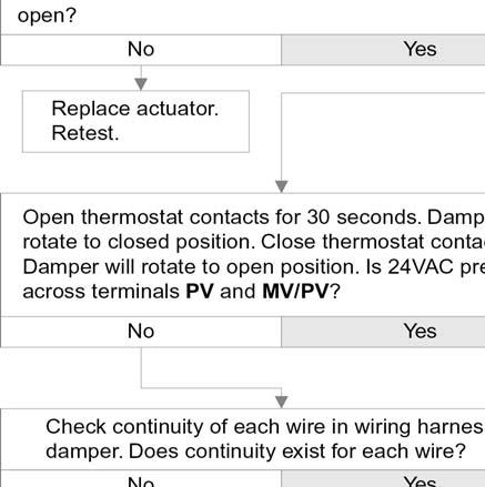
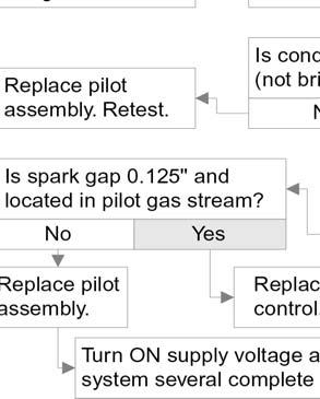
22 EGH-105 to EGH-125 Control Supplement Check-out procedure troubleshooting Verify proper operation after servicing Never jumper (bypass) any device except for momentary testing as outlined in Troubleshooting Charts. Substantial property damage and/or severe personal injury could occur. Burner access panel must be in position during boiler - property damage will result. Label all wires prior to disconnection when servicing controls. Wiring errors can cause improper and dangerous operation. Before troubleshooting: a. Have a voltmeter that can check 120VAC, 24VAC, a microammeter with minimum scale range of 0 25, and continuity tester. b. Check for 120VAC (minimum 102 maximum 132) to boiler. c. Check for 24VAC at secondary side of transformer. d. Make sure thermostat is calling for heat and contacts (including appropriate zone controls) are closed. Check for 24VAC between thermostat wire nuts and ground. In event of actuator failure: If troubleshooting chart recommends replacing actuator and actuator is not immediately available, damper blade can be fixed in an open position to allow boiler operation. Manually turning blade can cause actuator damage. Follow these instructions only in case of no heat or damper actuator malfunction. See Figure Move damper service switch to HOLD DAMPER OPEN Apply call for heat to boiler. Damper blade should then rotate to open position and boiler will fire. 2. If Step 1 does not open damper, manually rotate damper blade to open position using wrench or (Figure 10). Boiler will fire. Verify that damper service switch is in HOLD DAMPER OPEN 3. Do not leave damper permanently in this position. Replace actuator immediately. If damper is left in open position, boiler will not operate at published efficiencies. If troubleshooting chart recommends replacing actuator and actuator is not immediately available, damper blade can be fixed in an open position to allow boiler operation. Follow these instructions only in case of no heat or damper actuator malfunction. See Figure Turn off power to boiler. Failure to turn off power to boiler can result in severe personal injury, death or substantial property damage. 2. Refer to damper manufacturer s instructions for procedure to fix damper in open position. 3. Turn on power to boiler. manually rotate damper blade until green light turns on. Boiler will fire. 5. Do not leave damper permanently in this position. Replace actuator immediately. If damper is left in open position, boiler will not operate at published efficiencies. Figure 10 Temporary manual opening of vent damper refer also to vent damper manufacturer s instructions. 22 Part Number /1112
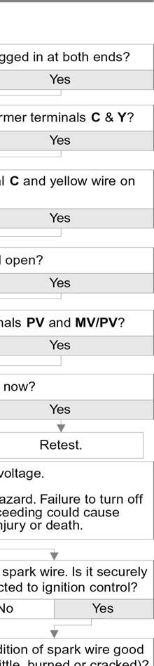
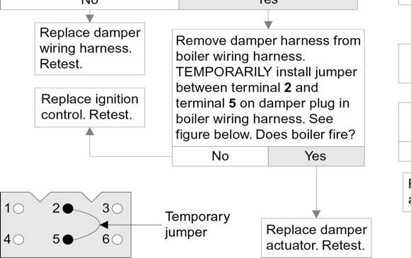
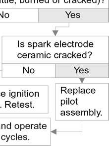
23 CSD-1 control system Natural gas Check-out procedure troubleshooting TS-1: Spark System (boiler without vent damper) does not work VISUALLY CHECK Is ground wire connected from GND (Burner) to ignition control mounting screw, and ground wire connected from transformer terminal C to case ground? Correct by making connections. Check for open thermostat, circulator relay, operating control, limit control or LWCO. Check the CSD-1 control panel, impulse relay and push-button switch. If limit controls or water level controls lockout on manual reset, determine cause and correct condition. Failure to do so could result in severe personal injury, death or substantial property damage. Is 24VAC present across terminals 24V and 24V(GND)? Open thermostat (or operating control) contacts for 15 seconds. Close thermostat contacts. Is 24VAC across terminals PV & MV/PV? Replace ignition control. Retest. Turn OFF supply voltage. Electrical shock hazard. Failure to turn off power before proceeding could cause severe personal injury or death. Securely connect spark wire. Then turn ON supply voltage. Retest. Check spark wire. Is it securely connected to spark transformer? Replace pilot assembly. Retest. Is condition of spark wire good (not cut, brittle, burned or cracked)? Is spark gap 0.125" and isolated in pilot gas stream? Is spark electrode ceramic cracked? Replace pilot assembly, turn ON supply voltage. Operate system several complete heat cycles. Replace ignition control. Retest. Replace pilot assembly, turn ON supply voltage, operate system several complete heat cycles. Part Number /


24 EGH-105 to EGH-125 Control Supplement Check-out procedure troubleshooting 24 Part Number /1112
25 CSD-1 control system Natural gas Check-out procedure troubleshooting TS-3: Pilot lights Main valve will not come on (boiler with or without damper) Does spark stay on for more than a few seconds after pilot is established? Is 24VAC between terminals MV and MV/PV on ignition control? Turn OFF supply voltage. Electrical shock hazard. Failure to turn off power before proceeding could cause severe personal injury or death. Replace ignition control. Retest. Is inlet gas pressure at least 5.0" W.C. and not over 14" W.C.? Contact gas supplier to correct. Is main valve wiring secure at terminals? Correct wiring. Retest. Replace valve. Retest. Check for continuity of sense wire and condition of insulation. NOT OK OK Make sure sense wire is not wrapped around any pipe or accessories. Is sense wire securely attached to sense terminal and pilot assembly? Correct and retest. Is sensing probe ceramic cracked? Replace pilot assembly. Retest. Is sense wire or sensing probe shorted out to metal surface? Correct and retest. Replace pilot assembly. Retest. Replace ignition control. Retest. Does system have proper flame signal? Set up microammeter to measure output current in flame sensor circuit as follows. a. Detach sense lead from ignition control. Attach negative lead from microammeter to sense terminal on ignition control. b. Attach positive lead to sense wire from pilot assembly. c. Disconnect main valve lead from terminal MV on ignition control. d. Energize the system. Spark should ignite the pilot. As soon as pilot is burning, microammeter should read at least 0.5 microamp for U.T. # e. Is flame current signal less than the minimum specified in d above? Check for proper gas pressure, clean pilot assembly, tight mechanical and electrical connections. Also check for proper system grounding per following page. Part Number /
26 EGH-105 to EGH-125 Control Supplement Check-out procedure troubleshooting TS-3: Pilot lights Main valve will not come on - continued from previous page Pilot assembly and ignition control must share common ground with main burner. Nuisance shutdowns are often caused by poor or erratic ground. Check for good metal-to-metal contact between pilot burner bracket and main burner and between main burner and burner rest. Turn OFF supply voltage. Electrical shock hazard. Failure to turn off power before proceeding could cause severe personal injury or death. To check ignition system grounding (instruction for continuation of TS-3) Check ground lead from GND (Burner) terminal on ignition control to ignition control mounting screw and from C on transformer to transformer case ground. Make sure connections are clean and tight. If wire is damaged or deteriorated, replace with. 18 gauge moisture-resistant, thermoplastic insulated wire with 105 C minimum rating. TS-4: Spark is present - pilot will not light (boiler with or without damper) Are pilot valve wiring connections CORRECT and securely fastened? Connect securely to terminal PV on ignition control and terminal TR on main gas valve. Is inlet gas pressure at least 5.0" W.C. and not over 14" W.C.? Is pilot shutoff valve open? Is gas present at pilot burner assembly? Open pilot shutoff valve. Contact gas supplier to correct gas pressure. Remove MV wire from ignition control. Use a match taped to a long screwdriver or pilot lighter rod and manually light pilot. Make sure pilot shutoff valve is open, 24VAC is present to pilot valve and pilot line is not kinked or obstructed. Check for clean pilot orifice. If OK, replace pilot gas valve. Is spark gap 0.125" and located in pilot gas stream? Replace pilot assembly. Block any draft around boiler. Check for clean pilot orifice. 26 Part Number /1112
27 CSD-1 control system Natural gas Service and maintenance Complete Installation and Service Certificate in, page 27. Follow, for service and maintenance of boiler. Part Number /
28 EGH-105 to EGH-125 Control Supplement Replacement parts steam boilers Figure 11 Steam boiler assembly MV MV MV/PV MV/PV PV PV ALARM ALARM ALARM ALARM 24 V 24 V 24 V (GND) 24 V (GND) SENSE SENSE SPARK SPARK b 22 23a a Part Number /1112
29 CSD-1 control system Natural gas Table 3 Steam boiler replacement parts Before replacing any parts on the boiler Turn off power to boiler and shut off gas supply. Failure to comply could result in severe personal injury, death or substantial property damage. Item Description Boiler Model Supplier Manufacturer part number Weil-McLain part number 1 Main burner, stainless steel EGH Weil-McLain Main burner, SS with pilot bracket EGH Weil-McLain Pilot burner (not shown) EGH PSE E48A Main gas valve EGH Robertshaw 7000DERHC-S7C Manual gas valve, 1 NPT EGH Watts FBV Leak test valve EGH Key Gas Pilot gas valve EGH Honeywell V8046C a Pilot gas pressure regulator EGH Maxitrol RV20VL Pilot shutoff valve EGH Conbraco Pilot tubing, Alum. 1/8 O.D. x 34 long EGH Available at local supply house 11 Ignition control EGH United Technologies Impulse relay EGH S89R-11ABD Push-button switch EGH Lens cover EGH Honeywell Eaton Controls Honeywell Eaton Controls AML21CBA2AA 221K11810 AML51-C10R 220PM02A 15 Light bulb EGH TI-3/4 Available at local supply house Wiring harness, pumped return steam Wiring harness, gravity return steam Vent damper assembly optional (not for use in Canada) EGH Weil-McLain EGH EGH EGH Field Controls Johnson Field Controls Johnson RVGP-KS-10BKF GVD-10 Q35GP-2 (note 1) RVGP-KS-12BKF Controls GVD-12 Q35GR-2 (note 1) Vent damper actuator EGH RVGP Vent damper harness EGH Weil-McLain Limit control, automatic reset EGH Honeywell White-Rodgers PA-404-A P47EA Limit control, manual reset EGH Honeywell L4004C Probe LWCO, manual reset EGH McDonnell & Miller PS852M a Float LWCO, automatic reset EGH McDonnell & Miller 67W b Float LWCO/ pump control auto reset EGH McDonnell & Miller 42-A Pressure gauge EGH Ametek P505K Transformer/relay EGH Honeywell R8285D te 1 Johnson damper assembly consists of M35BC actuator and Y15 vent pipe. Replacement parts must be purchased through a local Weil-McLain distributor. When ordering, specify boiler model and not be covered by warranty and may damage boiler or impair operation. Refer to boiler manual for parts not listed above. Part Number /
30 EGH-105 to EGH-125 Control Supplement tes 30 Part Number /1112
31 CSD-1 control system Natural gas tes Part Number /
32 EGH-105 to EGH-125 Control Supplement 32 Part Number /1112
LGB Gas fired boiler
 LGB Gas fired boiler Control Supplement LGB-5 Series 2 Propane gas CSD-1 Control System Part Number 550-110-682/0304 Please read this page first Hazard definitions To the installer... The following terms
EG & PEG Series 5 EGH Series 5
 EG & PEG Series 5 EGH Series 5 Gas-Fired Boilers Control supplement Universal control systems For additional information, refer to... for EG/PEG Natural gas only (Propane) gas (tankless heater application
LGB. Control Supplement. Gas fired boiler. Universal Control System. Series 2 Propane gas. Contents
 LGB Gas fired boiler Control Supplement LGB-6 to LGB-23 Series 2 Propane gas Universal Control System Contents I. New installation... 2 II. Existing installation... 4 III. Gas piping... 5 IV. Wiring...
CSD-1 COMMERCIAL BOILER CONTROLS
 SUPPLEMENTAL INSTALLATION AND OPERATING INSTRUCTIONS CSD- COMMERCIAL BOILER CONTROLS P/N 400043, Rev. A [/03] CSD- COMMERCIAL BOILER CONTROLS! WARNING Fire, explosion, asphyxiation and electrical shock
Internet Version for Reference Only INDUCED DRAFT COMMERCIAL WATER HEATERS SUPPLEMENT INSTRUCTIONS TO PART #
 INDUCED DRAFT COMMERCIAL WATER HEATERS SUPPLEMENT INSTRUCTIONS TO PART #238-39387-00 THIS INSTRUCTION SUPPLEMENT IS ONLY INTENDED TO GIVE INSTALLATION INSTRUCTIONS AND INFORMATION RELATED TO THE INDUCED
XIII Troubleshooting
 XIII Troubleshooting The following pages contain troubleshooting charts for use in diagnosing control problems. To use these charts, go to the box marked Start at the top of the chart on page 34 or 36
OPERATING INSTRUCTIONS MANUAL (Please retain for future reference) FVN/P-400 INDIRECT FIRED SPACE HEATERS
 FVN/P-400 INDIRECT FIRED SPACE HEATERS") OPERATING INSTRUCTIONS MANUAL (Please retain for future reference) For FVN/P-400 INDIRECT FIRED SPACE HEATERS CERTIFIED FOR USE IN CANADA AND U.S.A. As per Standard ANSI Z83.7/CSA 21.4 2000 Gas Fired Construction
OPERATING INSTRUCTIONS MANUAL (Please retain for future reference) For FVN/P-400 INDIRECT FIRED SPACE HEATERS CERTIFIED FOR USE IN CANADA AND U.S.A. As per Standard ANSI Z83.7/CSA 21.4 2000 Gas Fired Construction
COMMERCIAL 24 VOLT FLUE DAMPER
 COMMERCIAL 24 VOLT FLUE DAMPER SERIES WATER HEATER Gas Water Heaters SERVICE MAUAL Troubleshooting Guide and Instructions for Service (To be performed OL by qualified service providers) Models Covered
Contents. Hazard definitions
 GWS-090E Gas-Fired Water Boiler Boiler Manual Contents Page 1 Prepare boiler location...2 2 Prepare boiler...8 3 Install water piping...9 4 Venting and combustion air...12 5 Gas piping...12 6 Field wiring...13
CG Section and Base Assembly Series 1 through 12
 GAS CG Section and Base Assembly Series through 2 5 3 2 2 3 4 9 6 8 0 8B 0A 7 22 Discontinued Service Parts CG Section and Base Assembly Series through 2 GAS Fig. No. Part No. Description Series No. 3-03-85
Energy Manager INSTALLATION INSTRUCTIONS. Keep these instructions with the boiler at all times for future reference
 INSTALLATION INSTRUCTIONS Energy Manager Keep these instructions with the boiler at all times for future reference BOYERTOWN FURNACE CO. PO Box 100 BOYERTOWN, PA 19512 1-610-369-1450 www.boyertownfurnace.com
prestige Condensing Water Boiler SERVICE TECHNICIAN S TROUBLE SHOOTING GUIDE TSG-SOLO-9/04
 prestige Condensing Water Boiler SERVICE TECHNICIAN S TROUBLE SHOOTING GUIDE 2004-28 TSG-SOLO-9/04 Table of Contents INTRODUCTION Page 1 SERVICING TIPS AND INSTRUCTIONS Page 3 CONTROL MODULE DISPLAY -
OPERATING INSTRUCTIONS MANUAL (Please retain for future reference) FVN/P-400 INDIRECT FIRED SPACE HEATERS
 FVN/P-400 INDIRECT FIRED SPACE HEATERS") OPERATING INSTRUCTIONS MANUAL (Please retain for future reference) For FVN/P-400 INDIRECT FIRED SPACE HEATERS CERTIFIED FOR USE IN CANADA AND U.S.A. As per Standard ANSI Z83.7/CSA 21.4 2000 Gas Fired Construction
OPERATING INSTRUCTIONS MANUAL (Please retain for future reference) For FVN/P-400 INDIRECT FIRED SPACE HEATERS CERTIFIED FOR USE IN CANADA AND U.S.A. As per Standard ANSI Z83.7/CSA 21.4 2000 Gas Fired Construction
LGB COMMERCIAL GAS BOILER. Versatile combustion control systems. Made with Weil-McLain quality COMMERCIAL GAS BOILER APPLICATIONS INCLUDE:
 www.weil-mclain.com COMMERCIAL GAS OILER Series Gas Water or Steam MH: 400-,860 Efficiency 85.% Net Load Range: Hot Water 80-, MH / Steam 975-7,40 Sq. Ft. COMMERCIAL GAS OILER APPLICATIONS INCLUDE: Apartment
Instruction manual Supplement
 Instruction manual Supplement Replace manual pages: Replace manual page:...with page: Page 10... 2 Page 11... 3 Page 12... 4 Page 13... 5 Page 14 & 15... 6 Page 16... 7 Page 17... 8 Page 18... 9 Page 20...
SLANT/FIN AUTOMATIC VENT DAMPER For Galaxy, Sentinel and Sentry Series Boilers INSTALLATION INSTRUCTION MANUAL AND TROUBLESHOOTING GUIDE
 INSTALLATION INSTRUCTION MANUAL AND TROUBLESHOOTING GUIDE SLANT/FIN AUTOMATIC VENT DAMPER For Galaxy, Sentinel and Sentry Series Boilers The installation must conform to the requirements of the authority
USER S INFORMATION MANUAL
 USER S INFORMATION MANUAL HOT WATER HEATING BOILERS DOMESTIC WATER HEATERS 150,000-300,000 Btu/hr MODELS EB-EWU-02 IMPORTANT INSTALLER - AFFIX INSTALLATION MANUAL ADJACENT TO THE BOILER CONSUMER - RETAIN
SUPER HIGH EFFICIENCY WATER HEATERS SUPPLEMENT TO INSTRUCTION MANUAL P/N (Replaces pg. 2 in instruction manual.) CONGRATULATIONS!
 CONGRATULATIONS!") SUPER HIGH EFFICIENCY WATER HEATERS SUPPLEMENT TO INSTRUCTION MANUAL P/N 238-44219-00 (Replaces pg. 2 in instruction manual.) CONGRATULATIONS! You have just purchased one of the finest water heaters on
SUPER HIGH EFFICIENCY WATER HEATERS SUPPLEMENT TO INSTRUCTION MANUAL P/N 238-44219-00 (Replaces pg. 2 in instruction manual.) CONGRATULATIONS! You have just purchased one of the finest water heaters on
prestige Condensing Water Boiler SERVICE TECHNICIAN S TROUBLE SHOOTING GUIDE TSG-PRESTIGE Date revised: 11/10/08
 prestige Condensing Water Boiler SERVICE TECHNICIAN S TROUBLE SHOOTING GUIDE Date revised: 11/10/08 2008-36 TSG-PRESTIGE Table of Contents INTRODUCTION Page 1 SERVICING TIPS AND INSTRUCTIONS Page 3 CONTROL
southbend A MIDDLEBY COMPANY INSTALLATION AND OPERATION MANUAL CG214 (E) CG314 (E) CG414 (E) CG220 (E) CG320 (E) CG325 (E) GAS BOILERS MODELS:
 CG314 (E) CG414 (E) CG220 (E) CG320 (E) CG325 (E) GAS BOILERS MODELS:") INSTALLATION AND OPERATION MANUAL GAS BOILERS MODELS: CG214 (E) CG314 (E) CG414 (E) CG220 (E) CG320 (E) CG325 (E) southbend A MIDDLEBY COMPANY 1100 Old Honeycutt Road Fuquay-Varina, NC 27526 (919) 552-9161
INSTALLATION AND OPERATION MANUAL GAS BOILERS MODELS: CG214 (E) CG314 (E) CG414 (E) CG220 (E) CG320 (E) CG325 (E) southbend A MIDDLEBY COMPANY 1100 Old Honeycutt Road Fuquay-Varina, NC 27526 (919) 552-9161
WARNING WARNING TROUBLESHOOTING GUIDE INTEGRATED FURNACE CONTROL MODULE
 TROUBLESHOOTING INTEGRATED FURNACE Failure to read and follow all instructions carefully before installing or operating this control, could cause personal injury and/ or property damage. 50A55 INTEGRATED
OPERATING INSTRUCTIONS MANUAL (Please retain for future reference) FVN/P-400 INDIRECT FIRED SPACE HEATERS
 FVN/P-400 INDIRECT FIRED SPACE HEATERS") OPERATING INSTRUCTIONS MANUAL (Please retain for future reference) For FVN/P-400 INDIRECT FIRED SPACE HEATERS CERTIFIED FOR USE IN CANADA AND U.S.A. As per Standard ANSI Z83.7/CSA 21.4 2000 Gas Fired Construction
OPERATING INSTRUCTIONS MANUAL (Please retain for future reference) For FVN/P-400 INDIRECT FIRED SPACE HEATERS CERTIFIED FOR USE IN CANADA AND U.S.A. As per Standard ANSI Z83.7/CSA 21.4 2000 Gas Fired Construction
95M-200. Gas-Fired Direct Vent Modulating Hot Water Boiler. Control Manual And Troubleshooting Guide. P/N , Rev.
 95M-200 Gas-Fired Direct Vent Modulating Hot Water Boiler Control Manual And Troubleshooting Guide P/N 24000604, Rev. C [04/09] WARNING! Revise boiler control parameters only if you fully understand the
Replacement parts EG/PEG
 Replacement parts EG/PEG Table 13 EG/PEG replacement parts A B Left hand end section with heater opening (Pattern No. 1814) Left end section without heater opening(pattern No. 1813) Right hand end section
BGH Series Hot Surface Ignition Control
 Installation Instructions BGH Series Issue Date April 14, 2011 BGH Series Hot Surface Ignition Control Application The BASO Gas Products BGH Series Hot Surface Ignition (HSI) control is microprocessor
OPERATING INSTRUCTIONS MANUAL (Please retain for future reference) F-1500T DUAL FUEL CONSTRUCTION HEATER
 F-1500T DUAL FUEL CONSTRUCTION HEATER") OPERATING INSTRUCTIONS MANUAL (Please retain for future reference) For F-1500T DUAL FUEL CONSTRUCTION HEATER CERTIFIED FOR USE IN CANADA AND U.S.A. As per Standard ANSI Z83.7 2000/ CSA 2.14 2000 Gas Fired
OPERATING INSTRUCTIONS MANUAL (Please retain for future reference) For F-1500T DUAL FUEL CONSTRUCTION HEATER CERTIFIED FOR USE IN CANADA AND U.S.A. As per Standard ANSI Z83.7 2000/ CSA 2.14 2000 Gas Fired
24 VAC SYSTEM CONTROL KIT
 24 VAC SYSTEM CONTROL KIT Model: CK-92F and CK-92FG Designed for use with the SWG Series Power Venter for controlling Natural Gas or L.P. Gas appliances with a 24 VAC Gas Valve and a 30-millivolt controlled
24 VAC Intermittent Pilot Gas Ignition Control
 C610U Universal 24 VAC Intermittent Pilot Gas Ignition Control Issue Date: 08/24/2016 Quick Reference Guide The C610U Universal Intermittent Pilot Gas Ignition Control module replaces many popular flame
Models CHB/CCB APPLICATION GUIDE WALL MOUNTED GAS BOILER
 Models CHB/CCB APPLICATION GUIDE WALL MOUNTED GAS BOILER This manual has been prepared for use with the appropriate Installation, Operation and Maintenance Manual. For use with CCB/CHB Boilers ONLY. Manufactured
MGB CAST IRON GAS FIRED BOILERS FOR FORCED HOT WATER With Hydrolevel Control. Models MGB-50J MGB-75J MGB-100J MGB-125J MGB-150J MGB-170J MGB-200J
 Models MGB-50J MGB-75J MGB-100J MGB-125J MGB-150J MGB-170J MGB-200J MGB CAST IRON GAS FIRED BOILERS FOR FORCED HOT WATER With Hydrolevel Control INSTALLATION, OPERATION & MAINTENANCE MANUAL C.S.A. Certified
24 VAC SYSTEM CONTROL KIT
 24 VAC SYSTEM CONTROL KIT Model: CK-91F and CK-91FG Designed for use with the SWG Series Power Venter for controlling Natural Gas or L.P. Gas draft induced appliances with a 24 VAC Gas Valve and a 30-millivolt
Please read before proceeding
 Boiler Manual Please read before proceeding Installer Read all instructions before installing. Follow all instructions in proper order to prevent personal injury or death. Consider piping and installation
Heat Exchanger Block Replacement Instructions
 Series 1-4 Gas-fired water boiler Heat Exchanger Block Replacement Instructions Ultra-80 S1-4 Heat Exchanger Block Replacement Kit, Part No. 383-500-773 Ultra-105 S1-4 Heat Exchanger Block Replacement
OPERATING INSTRUCTIONS MANUAL (Please retain for future reference) F-400T DUAL FUEL CONSTRUCTION HEATER
 F-400T DUAL FUEL CONSTRUCTION HEATER") OPERATING INSTRUCTIONS MANUAL (Please retain for future reference) For F-400T DUAL FUEL CONSTRUCTION HEATER CERTIFIED FOR USE IN CANADA AND U.S.A. As per Standard ANSI Z83.7 2000/ CSA 2.14 2000 Gas Fired
OPERATING INSTRUCTIONS MANUAL (Please retain for future reference) For F-400T DUAL FUEL CONSTRUCTION HEATER CERTIFIED FOR USE IN CANADA AND U.S.A. As per Standard ANSI Z83.7 2000/ CSA 2.14 2000 Gas Fired
INSTALLATION INSTRUCTIONS
 INSTALLATION INSTRUCTIONS Keep these instructions with the boiler at all times. BOYERTOWN FURNACE CO. PO Box 100 BOYERTOWN, PA 19512 1-610-369-1450 www.boyertownfurnace.com 5-25-12 2 Danger Warning Caution
Conversion Instructions Logano G234X. Gas boiler. Please read carefully before installing and servicing. Gas boiler
 Gas boiler UPON COMPLETION OF THE INSTALLATION THE INSTALLER MUST INSTRUCT THE OWNER AND OPERATOR ON THE FUNCTIONALITY AND THE PROPER OPERATION OF THE BOILER AND THE HEATING SYSTEM. INSTALLER MUST REVIEW
THC 85 INDUSTRIAL / COMMERCIAL SPACE HEATER
 A Division of THC 85 INDUSTRIAL / COMMERCIAL SPACE HEATER Certified to / Certifié à CGA 2.14 M2000 Conforms to / Conforme à ANSI std Z83.7 2000 Suitable for indoor or outdoor installation / Unvented /
Contents. Hazard definitions
 GWA Series 2 Gas-Fired Water Boilers Boiler Manual Contents Page 1 Prepare boiler location...2 2 Prepare boiler...6 3 Install water piping...10 4 Install gas piping...13 5 Field wiring...14 6 Start-up...15
THC 85 / 175 INDUSTRIAL / COMMERCIAL SPACE HEATER
 THC 85 / 175 INDUSTRIAL / COMMERCIAL SPACE HEATER Certified to / Certifié à CGA 2.14 M2000 Conforms to / Conforme à ANSI std Z83.7 2000 Suitable for indoor or outdoor installation / Unvented / Unattended
Low Water Cutoff (LWCO) IQ Option Card p/n , for Hot Water Boilers
 IQ Option Card p/n , for Hot Water Boilers") Low Water Cutoff (LWCO) IQ Option Card p/n 102711-01, 102714-01 for Hot Water Boilers Instruction Sheet 102-360 APPLICATION The Low Water Cutoff (LWCO) IQ Option Cards are advanced, microprocessor based
Low Water Cutoff (LWCO) IQ Option Card p/n 102711-01, 102714-01 for Hot Water Boilers Instruction Sheet 102-360 APPLICATION The Low Water Cutoff (LWCO) IQ Option Cards are advanced, microprocessor based
ZG Shown READ ALL INSTRUCTIONS IN THIS MANUAL AND RETAIN FOR FUTURE REFERENCE WARNING
 See unit nameplate for manufacturer and address. 507258-04 7/2018 Supersedes 10/2017 ZG 036, 048, 060, 072, 074 (3, 4, 5 and 6 Tons) ZG 092, 102, 120, 150 (7-1/2, 8-1/2, 10 and 12 Tons) ROOFTOP UNITS ZG
Installation. Part Number /0209
 Installation The following picture replaces the one shown on page 3 of the boiler manual. 1. The change is the reversing of the orientation of the 3-way valve body (A - connects to system piping and B
Page. Hazard definitions
 G SA Gas-Fired Steam Boilers Boiler Manual Contents Page 1 Prepare boiler location...2 2 Prepare boiler...8 3 Install piping...11 4 Install controls...14 5 Install gas piping...15 6 Field wiring...16 7
Weil-McLain part numbers are found in Weil-McLain Boilers and Controls Repair Parts Lists.
 gas-fired water boiler Manual Replacement parts Replacement parts must be purchased through a local Weil-McLain distributor. When ordering, specify boiler model and size and include description and part
Contents. Hazard definitions
 GWS Gas-Fired Water Boilers Boiler Manual Contents Page 1 Prepare boiler location... 2 2 Prepare boiler... 8 3 Install water piping... 9 4 Venting and combustion air... 12 5 Gas piping... 12 6 Field wiring...
Control manual and troubleshooting guide
 Control manual and troubleshooting guide 95M-200 GAS-FIRED DIRECT VENT MODULATING HOT WATER BOILER! Revise boiler control parameters only if you fully understand the purpose and result of the changes.
! WARNING. McDonnell & Miller Installation & Maintenance Instructions MM-214(C) Series 61 Low Water Cut-Off OPERATION
 Series 61 Low Water Cut-Off OPERATION") Series 61 Low Water Cut-Off Typical Applications: - Primary or secondary low water cut-off for hot water and steam boilers. - Low water cut-off - High water cut-off - Alarm actuator OPERATION Maximum Boiler
Series 61 Low Water Cut-Off Typical Applications: - Primary or secondary low water cut-off for hot water and steam boilers. - Low water cut-off - High water cut-off - Alarm actuator OPERATION Maximum Boiler
THC 85N / 175N INDUSTRIAL / COMMERCIAL SPACE HEATER
 THC 85N / 175N INDUSTRIAL / COMMERCIAL SPACE HEATER Certified to / Certifié à CGA 2.14 M2000 Conforms to / Conforme à ANSI std Z83.7 2000 Suitable for indoor or outdoor installation / Unvented / Unattended
ELECTRONIC FIREPLACE DAMPER
 ELECTRONIC FIREPLACE DAMPER Model: FSE Low Profile Series The Flue Sentinel Electronic Fireplace Damper is designed to increase the comfort and energy efficiency of residential homes with gas-fired fireplaces.
MGB CAST IRON GAS FIRED BOILERS FOR FORCED HOT WATER. Models MGB-50J MGB-75J MGB-100J MGB-125J MGB-150J MGB-170J MGB-200J
 Models MGB-50J MGB-75J MGB-100J MGB-125J MGB-150J MGB-170J MGB-200J MGB CAST IRON GAS FIRED BOILERS FOR FORCED HOT WATER INSTALLATION, OPERATION & MAINTENANCE MANUAL C.S.A. Certified For Natural Gas Or
SERVICE TECHNICIAN ONLY read and follow completely.
 Parts list Table 7 Series 3 section and flue collector parts Item Description Part No. A Wide front section (7011) 316-700-245 B C D E Regular intermediate section (7015) Intermediate section w/draw rod
THC-175DF INDUSTRIAL / COMMERCIAL SPACE HEATER. Certified to / Certifié à CGA 2.14 M2011 Conforms to / Conforme à ANSI std Z83.
 THC-175DF INDUSTRIAL / COMMERCIAL SPACE HEATER Certified to / Certifié à CGA 2.14 M2011 Conforms to / Conforme à ANSI std Z83.7 2011 Suitable for indoor or outdoor installation / Unvented / Unattended
Indirect gas-fired air heater
 Indirect gas-fired air heater SERIES HD INSTALLATION AND SERVICE MANUAL MANUFACTURED BY : BROTHERS LIMITED WARNING Improper installation, modification, adjustment or maintenance may cause damage, injury
Fig. 1 - Unit PGD4, PGS4, WPG4
 OWNER S MANUAL 14 SEER Single -Package Air Conditioner and Gas Furnace System with R -410A Refrigerant Single Phase 2 to 5 Nominal Tons Three Phase 3 to 5 Nominal Tons PGD4andPGS4SeriesE,WPG4SeriesB Fig.
Multi-Function Cooktop
 INSTALLATION GUIDE Multi-Function Cooktop Contents Wolf Multi-Function Cooktop.................... 3 Multi-Function Cooktop Specifications............ 4 Multi-Function Cooktop Installation...............
AFUE 95% Heating Input 50,000 to 200,000 Btuh
 PRODUCT SPECIFICATIONS WATER HEATERS / BOILERS GWM-IE Gas-Fired, Modulating, Condensing, Wall Hung Hot Water Boiler Bulletin No. 210650 March 2018 Supersedes December 2015 AFUE 95% Heating Input 50,000
ELECTRONIC FIREPLACE DAMPER
 ELECTRONIC FIREPLACE DAMPER Model: FSE Series The Flue Sentinel Electronic Fireplace Damper is designed to increase the comfort and energy efficiency of residential homes with gas-fired fireplaces. Consisting
INSTALLATION AND OPERATION INSTRUCTIONS
 Printed in U.S.A. INSTALLATION AND OPERATION INSTRUCTIONS RCH100 CONSTRUCTION HEATER FLOOR MODEL WARNING IMPROPER INSTALLATION Improper installation, adjustment, alteration, service or maintenance can
Y8610U Intermittent Pilot Retrofit Kit
 Y8610U Intermittent Pilot Retrofit Kit PRODUCT DATA GENERAL The Y8610U is a complete kit for converting conventional standing pilot systems to intermittent pilot systems. It is used on gas-fired atmospheric
LATTNER BOILER COMPANY 9.5 HP Low-NOx Installation and Start-Up Checklist for Dry Cleaners
 1 1. General Installation Information (to be completed by technician) Date installed: Location (city & state): Cleaner s name: National Board number (boiler): Installed by (company): Installed by (technician):
User s Information Manual
 CGa, CGi, CGs, EG, EGH, LGB, PEG, PFG Gas-Fired Boilers User s Information Manual If the information in this manual is not followed exactly, a fire or explosion may result, causing property damage, personal
OBSOLETE. Y8610U Intermittent Pilot Retrofit Kit GENERAL FEATURES PRODUCT DATA. Contents
 GENERAL The Y860U is a complete kit for converting conventional standing pilot systems to intermittent pilot systems. It is used on gas-fired atmospheric furnaces, boilers, and heating appliances. Not
Y8610U Intermittent Pilot Retrofit Kit
 Y860U Intermittent Pilot Retrofit Kit PRODUCT DATA Each kit includes: S860U Intermittent Pilot Module. VR8304M Dual Valve Combination Gas Control. 3943 Igniter-Sensor. 394800-30 Ignition Cable. 39369 Natural
SERIES 35-63J APPLICATIONS FEATURES SPECIFICATIONS AGENCY CERTIFICATIONS
 SERIES 35-63J INSTALLATION INSTRUCTIONS FOR REPLACING JOHNSON CONTROLS G77X AND OTHER MODELS WITH FENWAL SERIES 35-63J IP IGNITION CONTROL APPLICATIONS The Fenwal 35-63J series Intermittent Pilot Ignition
INSTALLATION, OPERATING AND SERVICE INSTRUCTIONS GAS BOILER
 INSTALLATION, OPERATING AND SERVICE INSTRUCTIONS FORCESTM Series GAS BOILER 9700609 For service or repairs to boiler, call your heating contractor. When seeking information on boiler, provide Boiler Model
JD Series Cast Iron Commercial Hot Water or Steam Boiler
 JD Series Cast Iron Commercial Hot Water or Steam Boiler INSTALLATION, OPERATION & MAINTENANCE MANUAL An ISO 9001-2008 Certified Company Utica Boilers 2201 Dwyer Ave. Utica, NY 13501 Phone: (315) 797-1310
Electronic Ignition Water Heater
 Electronic Ignition Water Heater TROUBLE SHOOTING GUIDE Effective: 5/26/98 Guides are only intended for use on Atwood products by service technicians who have successfully completed Atwood training. This
TECHNICAL INSTRUCTIONS
 TECHNICAL INSTRUCTIONS Benchmark 3.0LN 24-Month Maintenance Kit# 58015-04 This kit applies to units with an Ignitor and a separate gas injector. For units with an Ignitor-Injector (P/N 58023), see Kit
ClearFire. Startup Guide. Model CFH. Horizontal Steam Boiler
 ClearFire Model CFH Horizontal Steam Boiler Startup Guide 750-293 www.cleaverbrooks.com Improper installation, adjustment, service, or maintenance can cause equipment damage, personal injury, or death.
SERIES 24. Series 24 Features. Commercial, Forced Draft, Hot Water or Steam Boiler. The right fit for any commercial job
 SERIES Commercial, Forced Draft, Hot Water or Steam Boiler Sizes from to,8 MBH output The right fit for any commercial job The Series is built to handle any installation - businesses, institutions, apartments,
Owner s Information Manual
 48ES---A and 48VL---A Comfort and Performance 13 and 14 SEER Single Packaged Air Conditioner and Gas Furnace System With Puron (R---410A) Refrigerant Single and Three Phase 2---5 Nominal Tons (Sizes 24---60)
GAS COOKTOP INSTALLATION INSTRUCTIONS
 INSTALLATION AND SERVICE MUST BE PERFORMED BY A QUALIFIED INSTALLER. IMPORTANT: SAVE FOR LOCAL ELECTRICAL INSPECTOR'S USE. READ AND SAVE THESE INSTRUCTIONS FOR FUTURE REFERENCE. WARNING If the information
Installation Instructions
 Installation Instructions Gas & Electric Dryer Before beginning installation, carefully read these instructions. This will simplify the installation and ensure the dryer is installed correctly and safely.
SERIES VAC Microprocessor-Based Intermittent Pilot Ignition Control FEATURES APPLICATIONS SPECIFICATIONS DESCRIPTION
 R SERIES 35-703 120 VAC Microprocessor-Based Intermittent Pilot Ignition Control F-35-703 July 2016 FEATURES Safe start with DETECT-A-FLAME flame sensing technology Custom pre-purge and inter-purge timings
Weil-McLain part numbers are found in Weil-McLain Boilers and Controls Repair Parts Lists.
 Replacement parts Replacement parts must be purchased through a local Weil-McLain distributor. When ordering, specify boiler model and size and include description and part of replacement part. Results
THC 85N / 175N INDUSTRIAL / COMMERCIAL SPACE HEATER
 THC 85N / 175N INDUSTRIAL / COMMERCIAL SPACE HEATER Certified to / Certifié à CGA 2.14 M2000 Conforms to / Conforme à ANSI std Z83.7 2000 Suitable for indoor or outdoor installation / Unvented / Unattended
Applies to: Models F, B, FE, and BE FOR YOUR SAFETY
 Form CP-F/B-GC (Version A) Obsoletes Form CP-F/B-GC Gas Conversion Kits and Instructions Applies to: Models F, B, FE, and BE Model B Model F All gas conversion must be done by a qualified service person
User s Information Manual
 Gas-fired Water boiler Series 2 NOTICE: Series 1/Series 2 identification Read the boiler rating plate to determine the series number. The rating plate is located on the right side of the boiler. User s
AFUE up to 83.9% Heating Input 50,000 to 299,000 Btuh
 HEATERS / BOILERS GWB8-E Gas-Fired Hot Water Boiler PRODUCT SPECIFICATIONS Bulletin No. 065 July 06 Supersedes September 05 AFUE up to 83.9% Heating Input 50,000 to 99,000 Btuh MODEL NUMBER IDENTIFICATION
SUPER HIGH EFFICIENCY WATER HEATERS SUPPLEMENT TO INSTRUCTION MANUAL P/N (Replaces pg. 2 in instruction manual.) CONGRATULATIONS!
 CONGRATULATIONS!") SUPER HIGH EFFICIENCY WATER HEATERS SUPPLEMENT TO INSTRUCTION MANUAL P/N 238-51012-00 (Replaces pg. 2 in instruction manual.) CONGRATULATIONS! You have just purchased one of the finest w ater heaters on
SUPER HIGH EFFICIENCY WATER HEATERS SUPPLEMENT TO INSTRUCTION MANUAL P/N 238-51012-00 (Replaces pg. 2 in instruction manual.) CONGRATULATIONS! You have just purchased one of the finest w ater heaters on
Contents. Hazard definitions
 GWA Gas-Fired Water Boilers Boiler Manual Contents Page 1 Prepare boiler location... 2 2 Prepare boiler... 6 3 Install water piping... 10 4 Install gas piping... 13 5 Field wiring... 14 6 Start-up... 15
GAS-FIRED STEAM BOILERS
 GAS-FIRED STEAM BOILERS COLUMBIA COMPANY Main offices and Factory: Pottstown, PA Models CEG075EID CEG112EID CEG150EID CEG187EID CEG225EID CEG262EID CEG299EID INSTALLATION, OPERATION & MAINTENANCE MANUAL
Columbia Boiler Company
 EMG Series Boilers Available in Natural Gas & Propane Rev 12012 Columbia Boiler Company PO Box 1070 Pottstown, PA 19464 Tel (610) 473-8457 Fax (610) 367-6800 Website www.columbiaboiler.com Email cbcsales@ptd.net
A-8-01 Typical questions and answers on the boiler specifications on tender and boiler contract documents
 Boiler specifications A-8-01 Typical questions and answers on the boiler specifications on tender and boiler contract documents Burner General: Q. Burner and burner safeguards shall comply with the CGA
25M01A-100 to 25M01A-199 HSI Single Stage Combination Gas Valve
 25M01A-100 to 25M01A-199 HSI Single Stage Combination Gas Valve INSTALLATION INSTRUCTIONS Operator: Save these instructions for future use! FAILURE TO READ AND FOLLOW ALL INSTRUCTIONS CAREFULLY BEFORE
Typical Mount Height. Combustion Chamber
 ! WARNING: This heater must be installed and serviced by trained gas installation and service personnel only! Improper installation, adjustment, alteration, service or maintenance can cause property damage,
*p * HWC4 Model THRU-THE-WALL UNIT INSTALLATION INSTRUCTIONS WARNING WARNING WARNING WARNING CAUTION CAUTION TABLE OF CONTENTS
 HWC4 Model THRU-THE-WALL UNIT INSTALLATION INSTRUCTIONS Save these instructions for future reference Improper installation, adjustment, alteration, service, or maintenance can cause injury or property
GOLD CGt. User s Information Manual. Natural gas-fired water boiler with tankless heater
 TM GOLD CGt Natural gas-fired water boiler with tankless heater User s Information Manual If the information in this manual is not followed exactly, a fire or explosion may result, causing property damage,
ECO1ZN3P, ECO2ZN4P ECO
 WARNING HOT This product may have hot fluid circulating through it. DO NOT TOUCH! SOME UNION NUTS MAY BECOME LOOSE AND CONSEQUENTLY LEAK THROUGH TRANSPORTATION VIBRATION AND HANDLING. DO NOT OVERTIGHTEN
Boiler Manual. Oil-Fired Steam Boilers. Maintenance Parts. Installation Startup
 Oil-Fired Steam Boilers Boiler Manual Installation Startup Maintenance Parts This manual must only be used by a qualified heating installer/service technician. BEFORE installing, read all instructions
12a. Replacement parts. GOLD CGs Gas-Fired Water Boiler Boiler Manual. Section assembly Base Jacket Trim Controls...
 12a Replacement parts Section assembly... 55 Base... 56 Jacket... 58 Trim... 60 Controls... 61 Replacement parts must be purchased through a local Weil-McLain distributor. When ordering, specify boiler
WPSB SERIES II. Models WPSB-3D WPSB-3DP WPSB-4D WPSB-4DP WPSB-5D WPSB-5DP WPSB-6D WPSB-6DP WPSB-7D WPSB-7DP WPSB-8D WPSB-8DP WPSB-9D WPSB-9DP
 Models WPSB-3D WPSB-3DP WPSB-4D WPSB-4DP WPSB-5D WPSB-5DP WPSB-6D WPSB-6DP WPSB-7D WPSB-7DP WPSB-8D WPSB-8DP WPSB-9D WPSB-9DP WPSB SERIES II GAS-FIRED HOT WATER BOILERS INSTALLATION, OPERATION & MAINTENANCE
OPERATING INSTRUCTIONS MANUAL (Please retain for future reference) F-1000T DUAL FUEL CONSTRUCTION HEATER
 F-1000T DUAL FUEL CONSTRUCTION HEATER") OPERATING INSTRUCTIONS MANUAL (Please retain for future reference) For F-1000T DUAL FUEL CONSTRUCTION HEATER CERTIFIED FOR USE IN CANADA AND U.S.A. As per Standard ANSI Z83.7 2000/ CSA 2.14 2000 Gas Fired
OPERATING INSTRUCTIONS MANUAL (Please retain for future reference) For F-1000T DUAL FUEL CONSTRUCTION HEATER CERTIFIED FOR USE IN CANADA AND U.S.A. As per Standard ANSI Z83.7 2000/ CSA 2.14 2000 Gas Fired
OWNER S MANUAL Manufactured Home Downflow Gas Furnace: MGD-B Series
 OWNER S MANUAL Manufactured Home Downflow Gas Furnace: MGD-B Series Heat Controller, Inc. 1900 Wellworth Ave. Jackson, MI 49203 (517)787-2100 www.heatcontroller.com Owner s Manual MGD-B SERIES GAS FURNACE
15B Cast Iron Gas Fired Boilers For Forced Hot Water
 Models 15B045FE 15B070FE 15B096FE 15B120FE 15B145FE 15B170FE 15B195FE 15B245FE 15B295FE 15B Cast Iron Gas Fired Boilers For Forced Hot Water INSTALLATION, OPERATION & MAINTENANCE MANUAL C.S.A. Certified
INSTALLATION INSTRUCTIONS FOR SERIES 9 INTERMITTENT PILOT IGNITION CONTROL
 INSTALLATION INSTRUCTIONS FOR SERIES 9 INTERMITTENT PILOT IGNITION CONTROL Figure 1 Series 9 Intermittent Pilot Ignition Control Application The Series 9 Intermittent Pilot Ignition Control is a microprocessor
STOP! Read this notice. STOP! Read before proceeding. These instructions are for gas conversion of the Evergreen boiler only.
 Series Identification Read the boiler rating label to determine the size and series number. CONDENSING GAS BOILER 220/299/300/399 Gas Conversion Instruction for Evergreen 220, 299/300 and 399 boilers Natural
COMMERCIAL GAS WATER HEATERS
 Service Handbook COMMERCIAL GAS WATER HEATERS P.O. Box 1597 Johnson City, TN 37605 MODELS (A)BCG385T500-8N & (A)BCG38T500-8P SERIES 120/121 INSTALLATION CONSIDERATIONS - PRE SERVICE CHECKS - WATER HEATER
SYSTEM CONTROL KIT. Model: CK-62. Designed for use on SWG Series Power Vent Hoods for controlling oil fired heating appliances with 120 VAC controls.
 SYSTEM CONTROL KIT Model: CK-62 Designed for use on SWG Series Power Vent Hoods for controlling oil fired heating appliances with 120 VAC controls. ITEMS INCLUDED IN KIT: 1) Junction box with mounted pressure