Operations Manual. 10 / 12 / 18 Vacuum Cool Tower Dryer Series MATHEWS COMPANY. Volume
|
|
|
- Verity Patterson
- 5 years ago
- Views:
Transcription


 323 7045 www.")

1 Volume 1 MATHEWS COMPANY 10 / 12 / 18 Vacuum Cool Tower Dryer Series 10 Vacuum Cool Tower 2011 Mathews Company 500 Industrial Avenue Crystal Lake, IL USA Toll Free Number: (800) Vacuum Cool Tower Effective: August, 2011 Operations Manual
2 OPERATIONS MANUAL 10 / 12 / 18 VACUUM COOL TOWER DRYER SERIES
3 Table of Contents SECTION 1: INTRODUCTION GRAIN DRYING THEORY FOR TOWER DRYERS FUNCTIONS OF AIR, HEAT, AND TIME SECTION 2: TOWER SERIES DRYER SPECIFICATIONS TOWER SERIES SPECIFICATIONS TOWER DIMENSIONS Dimensions Dimensions Dimensions Dimensions With No Grain Exchanger Dimensions With Grain Exchanger Dimensions With No Grain Exchanger Dimensions With Grain Exchanger Dimensions With No Grain Exchanger Dimensions With Grain Exchanger TOWER DRYER SPECIFICATIONS TOWER DIMENSIONS Dimensions Dimensions TOWER SPECIFICATIONS TOWER DIMENSIONS Dimensions Dimensions Dimensions SECTION 3: EQUIPMENT OVERVIEW OWNER /OPERATOR NOTES WARRANTY REGISTRATION MODEL AND SERIAL NUMBER LOCATION SAFETY PRECAUTIONS LOCK OUT / TAG OUT PROCEDURE REQUIREMENTS LOCKS BLOCKS GRAIN DRYER COMPONENT FUNCTION Field Device Components TOWER SERIES COMPONENTS BREAKDOWN REMOTE CABINET COMPONENTS Overview Pinnacle Pinnacle Lite TOWER HIGH VOLTAGE CABINETS Tower Direct Start High Voltage Tower Dryer Soft Start High Voltage Cabinet TOWER HIGH VOLTAGE CABINETS Tower Direct Start High Voltage Tower Soft Start High Voltage TOWER HIGH VOLTAGE CABINET Tri Start High Voltage
4 GAS TRAIN COMPONENTS Tower Gas Manifold Overview Tower Gas Manifold Overview Tower Gas Manifold Overview TOWER GAS SUPPLY & CONNECTIONS Tower LPG Tower NG Tower Canadian LPG TOWER GAS SUPPLY & CONNECTIONS Tower LPG Tower NG TOWER GAS SUPPLY & CONNECTIONS Tower NG PROPORTIONAL TEMPERATURE CONTROL Cal Controller Features TOWER IGNITION SYSTEM & 18 TOWER FIREYE FLAME CONTROLLER SECTION 4: OPERATING PROCEDURES START UP PROCEDURE General AIR PRESSURE SWITCH General Checking Adjusting FILLING THE DRYER SETTING THE GRAIN FLOW TIMER Conveyor Fill System (Slave System) Gravity Feed Tube System (Choke Fill System) GRAIN FLOW TIMER OPERATION IGNITING THE BURNER SETTING DRYING TEMPERATURE CAL CONTROLLER Cal Controller Wiring Temperature Set Point Temperature Set Point Changing Levels Parameters Domestic Settings Export Settings DISCHARGING THE DRYER Manual Discharge Mode Switching from Manual to Automatic Discharge (TruDry) Automatic Discharge Mode Moisture Control Setting and Adjustment Moisture Control Setting and Adjustment Switching From Automatic to Manual Discharge SHUTDOWN PROCEDURE End of Day Shutdown Next Day Startup Final Shutdown SECTION 5: DRYER MAINTENANCE
5 DRYER CLEANOUT RECOMMENDATIONS Cleaning the Outside of the Dryer SEASONAL CLEANOUT AND MAINTENANCE PRE SEASON DRYER CHECK POST SEASON DRYER MAINTENANCE IN CASE OF FIRE LUBRICATION CHART SECTION 6: TROUBLESHOOTING SAFETY CIRCUIT Troubleshooting the Safety Circuit Safety Circuit Schematic Customer Connections TEMPERATURE CONTROLLER (CAL) Controller Issues TEMPERATURE CONTROLLER INSTRUMENT PANEL FEATURES Adjustments VARIABLE FREQUENCY DRIVE (VFD) Keypad CODES that Display Faults on Drive AC Drive Parameters GENERAL PARAMETERS Minimum Discharge Rate Maximum Discharge Rate Current Limit of Discharge Rate Acceleration for Discharge Deceleration of Discharge VARIABLE FREQUENCY DRIVE (VFD) FAULT MENU VFD for Discharge System AC SOFT STARTER FOR BLOWER 10 & 12 TOWERS ONLY Fault Menu Parameters Soft Start Current Values CHANGING SOFT STARTER PARAMETERS Motor Current Current Limit Acceleration Time for Bypass Contactor Takeover Starting Torque Thermal Protection Voltage Boost IGNITION BOARD FIREYE FLAME CONTROLLER TROUBLESHOOTING Lockout Codes Diagnostic Messages COMMON START UP PROBLEMS START UP AND DRYER OPERATION SECTION 7: NOTES
6 Figures List FIGURE 1: TOWER DRYER AIRFLOW FIGURE 2: HIGH VOLTAGE CABINET INFORMATION DECAL FIGURE 3: "TOWER SERIES PANEL LISTING SPECIFICATIONS" FIGURE 4: LOCK OUT LOCK ASSEMBLY FIGURE 5: LOCK OUT TAG FIGURE 6: LOCK OUT SAFETY SIGN FIGURE 7: "10' TOWER CUT AWAY" FIGURE 8: "PINNACLE LITE REMOTE CABINET" FIGURE 9: PINNACLE REMOTE CABINET FIGURE 10: PINNACLE SUB PANEL ASSEMBLY FIGURE 11: PINNACLE LITE REMOTE CABINET FIGURE 12: "PINNACLE LITE SUB PANEL ASSEMBLY" FIGURE 13: 10 HIGH VOLTAGE DIRECT START SUB PANEL FIGURE 14: 10 HIGH VOLTAGE SOFT START SUB PANEL FIGURE 15: "12' HIGH VOLTAGE DIRECT START SUB PANEL" FIGURE 16: "12' HIGH VOLTAGE SOFT START SUB PANEL" FIGURE 17: "18' HIGH VOLTAGE TRI START SUB PANEL" FIGURE 18: "10' TOWER NG MANIFOLD" FIGURE 19: 10' TOWER LPG MANIFOLD" FIGURE 20: 12' TOWER LPG MANIFOLD" FIGURE 21: "12' TOWER NG MANIFOLD" FIGURE 22: "18' TOWER NG MANIFOLD" FIGURE 23: 10' LPG MANIFOLD FIGURE 24: 10' TOWER NATURAL GAS MANIFOLD FIGURE 25: "12' LPG MANIFOLD" FIGURE 26: "12' NG MANIFOLD" FIGURE 27: "18' NG MANIFOLD" FIGURE 28: BELIMO ACTUATOR FIGURE 29: TEMPERATURE CONTROLLER (CAL) FIGURE 30: "IGNITION BOARD" FIGURE 31: 10 TOWER IGNITION BOX FIGURE 32: 12 & 18 TOWER FIREYE CONTROL INSIDE VIEW FIGURE 33: "12' & 18' TOWER IGNITION BOX" FIGURE 34: 12 & 18 TOWER FIREYE CONTROL OUTSIDE VIEW FIGURE 35: GRAIN FLOW TIMER FIGURE 36: GRAVITY FEED TIMER FIGURE 37: TEMPERATURE CONTROLLER FIGURE 38: VARIABLE FREQUENCY DRIVE (VFD)... 67

7 Section 1 Section 1: Introduction Grain Drying Theory for Tower Dryers The equalizing of moisture in the grain to the air moisture is called grain drying. The process of drying grain in a Mathews Company Tower Series grain dryer requires 3 main components: 1. Air: Volume is supplied by a blower that is vertically mounted inside the dryer. The function of the air is two fold. The air acts as a heat transfer mechanism. The air assists the heat in penetrating the grain shell in order to dry the grain. The air absorbs the moisture from the grain and carries the moisture outside the dryer. 2. Heat/Energy: The burner that sits directly above the blower heats the air filling the plenum chamber, and transfers the heat to the grain. The heat releases the moisture from the grain. The accurate control of this heat is what makes the equipment energy efficient. The most effective way to regulate the control of this energy is through a gas control valve that opens and closes to allow fuel supply to change to keep the plenum temperature stable. 3. Time: Refers to the time the grain is spent inside the dryer. The time that the grain is exposed to both air and heat determines how much moisture is driven out of the grain. The longer the exposure, the more moisture removal occurs. Thus, the best method for controlling the amount of moisture removal in the grain is to increase and decrease the grain metering system of the dryer. The slower the metering system operates, the longer the grain is exposed to air and heat and the moisture removal is increased. The faster the metering system operates, the shorter the grain retention time and the moisture removal of grain is reduced. The easiest way to keep good grain quality and accurate control is to keep heat and air consistent while varying only grain retention time. This has proven to be the most common and efficient way to dry grain. Figure 1: - Tower Dryer Airflow DOC T Introduction 1.1
8 Functions of Air, Heat, and Time The bottom third of the dryer is suction cooled, pulling heat off the grain and returning it to the burner to lower energy consumption; this is the method of heat reclamation that creates the most efficient use of the energy in the dryer. The top two thirds of the dryer are pressure heated to dry grain. The air is pulled into the dryer through free air doors or grain columns. The amount of air volume the blower can move depends on the dryer pressure drop. The higher the pressure drop, the less air volume the blower moves. The free air doors have adjustable opening louvers. Increasing the amount of opening of the free air doors increases the air volume to the blower. The increased air volume will correlate to increased drying capacity. The free air door adjustment is also a means of controlling the discharge grain temperature. When the doors are closed, the discharge grain temperature will be closer to the ambient air temperature. The further the doors are opened, the higher the discharge temperature. The dryer plenum temperature control system provides a means to maintain a consistent plenum temperature. The temperature can be changed to an appropriate drying temperature for the type of grain being dried, and is the method used for greatest fuel efficiency. The blower pushes the air volume through the burner and the air transfers the heat to fill the plenum chamber and heats the grain. The grain will absorb the heat driving moisture out. The moisture emitted will saturate the air and the air will carry the moisture out of the dryer, leaving the grain hot. This heat will be reclaimed when it moves down the dryer column and is exposed to the suction cooling process resulting in fuel efficiency. 1.2 Introduction DOC T
9 Section 2 Section 2: Tower Series Dryer Specifications 10 Tower Series Specifications Model Total Height 32' 7" 36' 8" 40' 8" 44' 8" 52' 10" 60' 11" Outside Diameter 9' 9" 9' 9" 9' 9" 9' 9" 9' 9" 9' 9" Weight (lbs) 8,150 9,100 10,000 11,000 13,300 15,100 Grain Column Thickness 12" 12" 12" 12" 12" 12" Holding Capacity (bu) ,049 1,225 Diameter with Walkways 15' 9" 15' 9" 15' 9" 15' 9" 15' 9" 15' 9" Standard Number of Outside Walkways NA NA Max Burner Capacity (MMBTU/hr) Average Burner Capacity (MMBTU/hr) Number of Fans Fan Motor Size (HP) Electrical Load (208V/3ph/60Hz) Amps Electrical Load (230V/3ph/60Hz) Amps Electrical Load (460V/3ph/60Hz) Amps DOC T Dryer Specifications 2.1


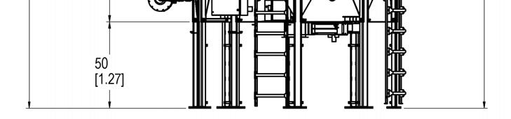
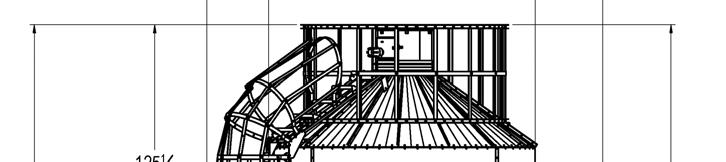
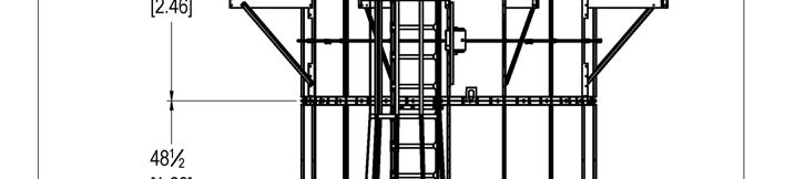
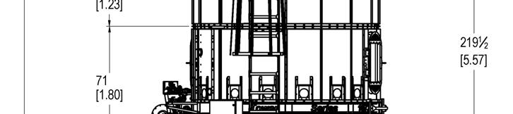
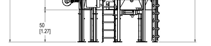
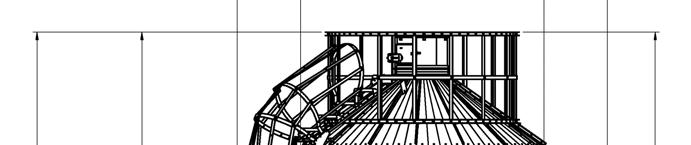
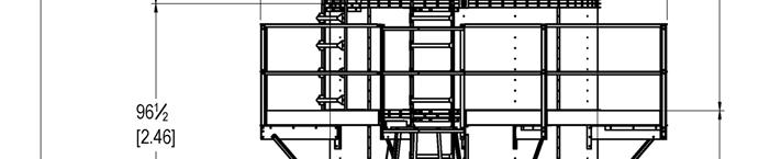
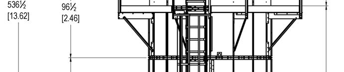
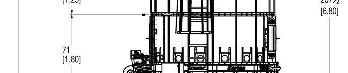
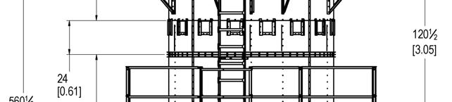
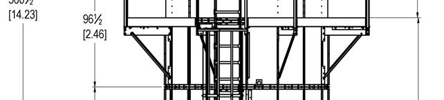
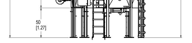
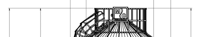
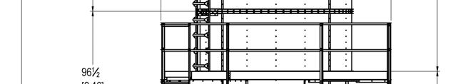
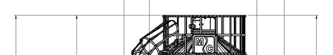
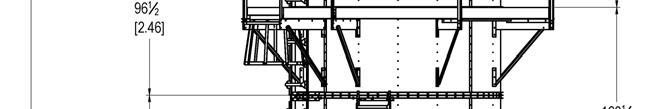
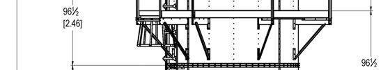
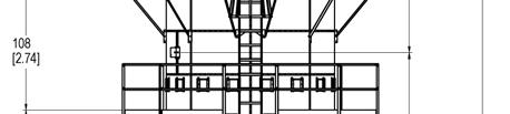
10 10 Tower Dimensions Dimensions Shown With Optional Walkway 2.2 Dryer Specifications DOC T

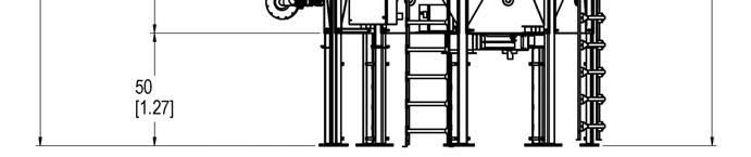
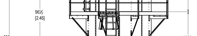
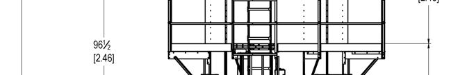
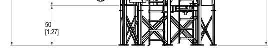
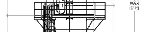
11 10630 Dimensions Shown With Optional Walkway DOC T Dryer Specifications 2.3

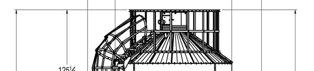
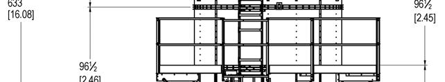
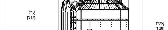
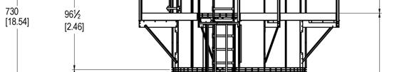
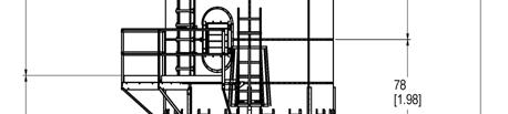
12 10730 Dimensions Shown With Optional Walkway 2.4 Dryer Specifications DOC T
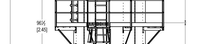
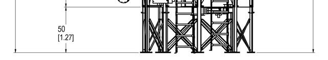
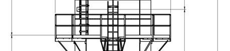
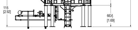
13 10840 Dimensions With No Grain Exchanger DOC T Dryer Specifications 2.5
14 10840 Dimensions With Grain Exchanger 2.6 Dryer Specifications DOC T

15 Dimensions With No Grain Exchanger DOC T Dryer Specifications 2.7


16 Dimensions With Grain Exchanger 2.8 Dryer Specifications DOC T


17 Dimensions With No Grain Exchanger DOC T Dryer Specifications 2.9
18 Dimensions With Grain Exchanger 2.10 Dryer Specifications DOC T
19 12 Tower Dryer Specifications Model Total Height 77' 3" 89' 3" Diameter 11' 8" 11' 8" Weight (lbs) 31,200 33,000 Grain Column Thickness 12" 12" Holding Capacity (bu) 1,945 2,268 Diameter with Walkways Number of Outside Walkways 2 3 Max Burner Capacity (MMBTU/hr) Average Burner Capacity (MMBTU/hr) Number of Fans 1 1 Fan Motor Size (HP) Electrical Load (208V/3ph/60Hz) Amps Electrical Load (230V/3ph/60Hz) Amps Electrical Load (460V/3ph/60Hz) Amps DOC T Dryer Specifications 2.11
20 12 Tower Dimensions 2000 Dimension Shown With Optional Walkway 2.12 Dryer Specifications DOC T

21 2400 Dimensions Shown With Optional Walkway DOC T Dryer Specifications 2.13
22 18 Tower Specifications Model Total Height 83' 8" 89' 8" 98' 8" Diameter 17' 6" 17' 6" 17' 6" Grain Column Thickness 12" 12" 12" Holding Capacity (bu) 3,711 3,962 4,339 Diameter with Walkways Number of Outside Walkways Max Burner Capacity (MMBTU/hr) Average Burner Capacity (MMBTU/hr) Number of Fans Fan Motor Size (HP) Electrical Load (208V/3ph/60Hz) Amps Electrical Load (230V/3ph/60Hz) Amps Electrical Load (460V/3ph/60Hz) Amps Dryer Specifications DOC T
23 18 Tower Dimensions 3000 Dimensions DOC T Dryer Specifications 2.15
24 3500 Dimensions 2.16 Dryer Specifications DOC T
25 4000 Dimensions DOC T Dryer Specifications 2.17

26 Section 3 Section 3: Equipment Overview Owner /Operator Notes This manual was prepared to provide owners and operators of Mathews Company 10 / 12 / 18 Vacuum Cool Tower Grain Dryers with operating instructions and maintenance information that will enable them to keep their M C Grain Dryers operating at peak efficiency. Before operating your grain dryer, read the Start Up and Operating Instructions. Become familiar with the controls, adjustments and settings required to obtain efficient operation. To keep the dryer operating at peak efficiency, it should be: CLEANED, LUBRICATED, BELT TENSION CHECKED, THE IGNITION SYSTEM CHECKED, FILL AND TEST DISCHARGE SYSTEM ADJUSTED. This should be done annually prior to the drying season. Refer to Pre Season Check in the Maintenance section. The Pre Season check can be made when the dryer is empty. Any necessary repairs or adjustments should be completed so that the dryer will be ready to operate before the drying season. Warranty Registration It is important to send in your warranty registration card as soon as your new grain dryer is delivered. Not only does the card validate your grain dryer s warranty, but it assists M C in disseminating information particular to your dryer model. Figure 3: "Tower Series Panel Listing Specifications" Figure 2: - High Voltage Cabinet Information Decal 3.1 Equipment Overview DOC T


27 Model and Serial Number Location The model, serial number and specifications of your Mathews Company continuous flow grain dryer are stamped on plates located on the base of the dryer. DOC T Equipment Overview 3.2
28 Safety Precautions 1. Read and understand the operations manual before attempting to operate the dryer. 2. Keep ALL guards, access doors, covers, safety decals, and safety devices in place and securely fastened. NEVER operate the dryer while guards are removed. 3. Keep all untrained personnel away from system components and control panels at all times. 4. NEVER attempt to operate the unit by jumping or otherwise bypassing any safety devices. 5. Always open the main power supply disconnect switch and lock it in the open position with an approved lockout device prior to performing any service or maintenance work on the fan or burner unit. 6. Lock out power before removing guards, access doors, and covers. 7. Keep hands, feet and clothing away from all rotating parts. 8. Electrical repairs should be performed by trained, qualified personnel only. Failure to follow safe electrical procedures can result in serious injury. 9. If it should become necessary to perform checks on system components or high voltage test with engaged circuits, proceed with extreme caution and follow all established safety practices. 10. Routinely check for any gas leaks. 11. Do not allow children or bystanders to be near the grain dryer or grain handling machinery while it is operating. 12. Do not operate the grain dryer without all safety shields in place and secure. Lock out / Tag out Procedure Requirements The purpose of a lock out/ tag out procedure is to prevent injury and/or death to personnel by requiring that certain precautions be taken before servicing or repairing equipment. This includes shutting off and locking out the electrical power source of the equipment. 1. All maintenance personnel are issued a suitable lock (or locks). The lock has the individual worker s name and other identification on it. That worker will have the only key to the lock. 2. Each person who will be working on the machinery should put a lock on the machine s lockout device(s). Each lock must remain on the machine until the work is completed. (Only the personnel who placed the lock should remove his/her lock.) 3. Check to be sure that no one is operating the machinery BEFORE turning off the power. The machine operator must be informed before the power is turned off. Sudden loss of power could cause an accident. 4. Any mechanism under load or pressure, such as springs, should be released and blocked. 5. All energy sources that could activate the machine must be locked out. 6. The main valve or main electrical disconnect must be tested to be sure that the power to the machine is OFF. 3.3 Equipment Overview DOC T


29 Locks 7. Electrical circuits must be checked by qualified persons with proper and calibrated electrical testing equipment. An electrical failure could energize the equipment, even if the switch is in the OFF position. Stored energy in electrical capacitors should be safely discharged. 8. CAUTION: Return disconnects and operating controls to the OFF position after each test. 9. Attach accident prevention tags, which give the reason for placing the tag, the name of the person placing the tag, how he/she many be contacted, and the date and time the tag was placed. No one removes the lock without proper authority. Each worker must have his/her own lock and the only key to that lock. The lock should be substantial, durable, and should have the name of the employee or personnel on it. In addition, locks can be color coded to indicate different shifts or types of services. Figure 5: - Lock Out Tag Figure 4: - Lock Out Lock Assembly DO NOT USE TAGS ALONE. Use tags or signs in addition to locks. Tags must state the: Reason for the lockout. Name of the employee or personnel who is working on the equipment and how that person may be reached. Date and time the tag was put in place. DOC T Equipment Overview 3.4

30 Blocks Suitable blocks are another important safety device for making a piece of equipment safe to be repaired or serviced. Blocks must be placed under raised dies, lifts, or any equipment that might inadvertently move by sliding, falling, or rolling. Blocks, special brackets, or special stands, such as those commonly used under raised vehicles, must be available at all times. Another form of blocking is the placement of a blind. A blind is a disk of metal placed in a pipe to ensure that no air or other substance will pass through that point if the system is accidentally activated. Before installing blinds or blocks, bleed down steam, air or hydraulic lines to get rid of any pressure. Coiled springs, spring loaded devices or suspended loads must also be released so that their stored energy will not result in inadvertent movement. Figure 6: - Lock Out Safety Sign 3.5 Equipment Overview DOC T
 Fill Switch The rotary fill switch is located in the receiving tube at the top of the dryer.")

31 Grain Dryer Component Function Field Device Components Ignition Board This board s function is to supply high voltage from the coil to either the spark or the igniter to ignite the burner. For continuous operation successful flame proving is necessary. Rotary (Bin) Fill Switch The rotary fill switch is located in the receiving tube at the top of the dryer. This is powered by 120 volts and contains normally open and closed contacts. The switch is motorized and will rotate a paddle until wet grain contacts the switch. The grain stops the rotation and proves the presence of grain. This switch is normally closed and allows the dryer to continue to fill as long as the switch rotates. When grain stops the device from rotating, the contact status changes to normally open and shuts off the fill system. High Limit Switch The high limit switch is located in the ignition box with a capillary bulb in the plenum chamber. This device is adjustable and should be set 40 degrees higher than the plenum temperature set point. If the plenum temperature reaches the high limit set point, the device will actuate and shut down the dryer. The highlimit switch is normally closed until the temperature reaches the set point, upon reaching the set point the contacts will open, shutting down the dryer. Air Pressure Switch The air pressure switch is an air flow proving device. The switch is fully adjustable, allowing the operator to set the air pressure switch to detect air or vacuum(18 Tower) when the machine is full of grain. The air pressure switch is normally open and will not close until sufficient air pressure/vacuum is detected. Once sufficient air flow is detected, the switch closes and provides 120 volts to the ignition, allowing the operator to ignite the burner. Temperature Controller Temperature Controller displays temperature outputs measured by the plenum RTD and commands the gas control valve. The valve will open, automatically adjust gas to maintain or stabilize the plenum temperature automatically. This device can also function to shut down the machine if the actual plenum temperature rises or falls more than 40 F. Belimo Valve Actuator Is an electrical proportional valve that responds to signals from a cal controller output, the cal controller receives the signal from the plenum RTD and then sends the signal to the Belimo Valve Actuator. From there it will modulate controlling the gas flow to maintain the plenum temperature. DOC T Equipment Overview 3.6

32 Mid Grain RTDs Mid Grain RTDs (Resistance Temperature Device) located on the side of the dryer are used to detect the temperature of the grain. Four mid grain RTDs are used to drive the TruDry Control System. Plenum RTD The Plenum RTD is a temperature sensing device used to transmit a signal to the temperature controller. It is located in the plenum chamber to monitor plenum air temperature. Discharge Moisture Sensor The discharge moisture sensor monitors the moisture and temperature of the discharge grain using a DC power and micro processing technology to change the DC signal to the moisture and temperature of discharging grain. Moisture is measured using capacitance to the ground. The temperature of the grain is measured by a thermocouple device on a moisture sensor. Linear Limit Devices (LLC) Located outside the grain column within an LLC Box wrapped around the top screen section of dryer (18 tower has the LLC located in the cooling section inside the dryer). The linear limit is an over temperature detection device. Spark Plug The spark plug receives high voltage current from the ignition board and arcs at the spark plug gap to provide direct spark ignition for the burner. Variable Frequency Drive (VFD) The VFD unit is a single phase input and three phase output device to run and protect the discharge motor. This device is controlled by the PLC. 3.7 Equipment Overview DOC T
 Fill Switch Linear")


33 Tower Series Components Breakdown Cal Controller Belimo Valve Rotary (Bin) Fill Switch Linear Limit Device Mid Grain RTD s Air Pressure Switch Ignition Board High Limit Switch Plenum RTD Spark Plug Ac (VFD) Drive Unit Figure 7: "10' Tower Cut Away" Moisture Sensor DOC T Equipment Overview 3.8


34 Remote Cabinet Components Overview Push Buttons These push buttons are used for starting and stopping the blower. LED Lights All lights are 120 volt power LED s for daylight viewable use. Rotary Switches These come in a variety of combinations and are typically used to actuate items on and off or switch modes OFF ON START. HMI Acronym stands for Human Machine Interface. This is the touch screen graphical display communication with the PLC. HMI LED Lights Push Buttons Rotary Switches Figure 8: "Pinnacle Lite Remote Cabinet" 3.9 Equipment Overview DOC T

35 Pinnacle HMI Remote Cabinet Emergency Stop Button Figure 9: - Pinnacle Remote Cabinet Breakers Terminal Blocks 24 VDC Power Supply Ethernet Switch Figure 10: - Pinnacle Sub Panel Assembly DOC T Equipment Overview 3.10


36 Pinnacle Lite HMI Remote Cabinet LED Lights Rotary Switches Push Buttons Emergency Stop Button Figure 11: - Pinnacle Lite Remote Cabinet MCR Breakers Terminal Blocks Ethernet Switch Cabinet Heater Light Figure 12: "Pinnacle Lite Sub Panel Assembly" 3.11 Equipment Overview DOC T

37 10 Tower High Voltage Cabinets 10 Tower Direct Start High Voltage 24 VDC Power Supply PLC Ethernet Purge Timer Module Analog Ground Lug Input/Output Card PLC CPU for PLC Disconnect Switch Ground Terminals Motor Protector Relays Ceramic Resistor Circuit Breakers RS485 to Ethernet for Cal Controller Motor Contactor Figure 13: - 10 High Voltage Direct Start Sub Panel DOC T Equipment Overview 3.12

38 10 Tower Dryer Soft Start High Voltage Cabinet 24 VDC Power Supply PLC Ethernet Module PLC CPU Analog Input/Output Card for PLC Cabinet Heater Ground Lug Disconnect Switch Ground Terminals Purge Timer Relays Soft Starter Terminal Blocks RS485 to Ethernet for Cal Controller Bypass Motor Contactor Ceramic Resistor Figure 14: - 10 High Voltage Soft Start Sub Panel 3.13 Equipment Overview DOC T

39 12 Tower High Voltage Cabinets 12 Tower Direct Start High Voltage 24 Volt Power Supply PLC Ethernet Module PLC CPU Analog Input Card for PLC Ground Lug Disconnect Switch Ground Terminals Motor Protector Relays Fireye Control Circuit Breakers RS485 to Ethernet for Cal Controller Figure 15: "12' High Voltage Direct Start Sub Panel" Motor Contactor DOC T Equipment Overview 3.14

40 12 Tower Soft Start High Voltage 24 Volt Power Supply PLC Ethernet Module PLC CPU Analog Input Card for PLC Cabinet Heater Ground Lug Disconnect Switch Ground Terminals Relays Soft Starter Fireye Control Circuit Breakers Terminal Blocks RS485 to Ethernet for Cal Controller Bypass Motor Contactor Figure 16: "12' High Voltage Soft Start Sub Panel" 3.15 Equipment Overview DOC T

41 18 Tower High Voltage Cabinet 18 Tri Start High Voltage 24 Volt Power Supply PLC Ethernet Module PLC CPU Analog Input Card for PLC Ground Terminals Ground Lug Disconnect Switch Motor Protector Relays Fireye Control Terminal Blocks Circuit Breakers RS485 to Ethernet for Cal Controller Motor Contactor Figure 17: "18' High Voltage Tri Start Sub Panel" DOC T Equipment Overview 3.16


42 Gas Train Components Strainer This item contains a wire filter and will collect foreign material that may find its way into the fuel supply line. Solenoid Valve The solenoid valve is controlled by the ignition board. 120 volt power will energize the solenoid coil and open the valve to allow fuel to flow to the burner. De energizing the solenoid coil will stop gas flow within one second and stops gas flow; extinguishing the burner flame. Control Valve This valve opens and closes to allow fuel supply to change and to keep the plenum temperature stable. This butterfly gas valve is directly controlled by the Belimo actuator which receives its signal from the cal controller in response to the plenum temperature. High Pressure Relief Valve When line pressure becomes too great, the valve automatically opens and relieves excess pressure until the pressure drops. Once pressure drops, the valve will close and seal for proper function. Low Gas Pressure Switch (Optional CE/CGA Systems Only) The low gas pressure switch is an adjustable pressure switch that will shut down the burner if pressure drops below the set point. The switch is adjustable, and can be set for any pressure from 0 to 9 psig. The normal low pressure setting is 50% of the low end range of manifold pressure. High Gas Pressure Switch (Optional CE/CGA Systems Only) The high gas pressure switch is an adjustable pressure switch that will shut down the grain dryer if the pressure rises above the set point on the switch. The switch is adjustable and can be set for any pressure from 0 to 20 psig. The normal high pressure setting is 50% above high end range of manifold pressure. Hand Valve A mechanically operated ball valve used to manually open and close fuel supply to the burner Equipment Overview DOC T


43 Pressure Regulator Reduces the pressure regulator pressure input to a controlled and adjustable output. These devices have different configurations and sizes but functionally perform two tasks; pressure reduction and stabilization of output within reasonable ranges. 10 Tower Gas Manifold Overview Figure 19: 10' Tower LPG Manifold" Figure 18: "10' Tower NG Manifold" 12 Tower Gas Manifold Overview Figure 20: 12' Tower LPG Manifold" Figure 21: "12' Tower NG Manifold" 18 Tower Gas Manifold Overview Figure 22: "18' Tower NG Manifold" DOC T Equipment Overview 3.18

44 10 Tower Gas Supply & Connections 10 Tower LPG High Pressure Switch Hand Valve Control Valve Low Pressure Switch Low Pressure Gauge Drip Leg Hand Valve High Pressure Gauge Pressure Regulator Figure 23: - 10' LPG Manifold 3.19 Equipment Overview DOC T

45 10 Tower NG Control Valve Gas Solenoid #2 Drip Leg Hand Valve Gas Solenoid #1 Pressure Regulator Low Pressure Gauge Figure 24: - 10' Tower Natural Gas Manifold DOC T Equipment Overview 3.20

46 10 Tower Canadian LPG High Gas Pressure Switch Gas Solenoid Low Gas Pressure Switch Liquid Infeed Line Hand Valve Vapor Vent Hook Up Drip Leg Liquid Vent Hook Up Pressure Gauge Pressure Regulator 3.21 Equipment Overview DOC T
47 12 Tower Gas Supply & Connections 12 Tower LPG Downstream Pressure Maxon Shutoff Pressure Regulator Solenoid Hand Valve Drip Leg Pressure Gauge Control Valve Figure 25: "12' LPG Manifold" DOC T Equipment Overview 3.22
48 12 Tower NG Control Valve Pressure Regulator Downstream Pressure Control Line Maxon Shutoff Drip Leg Hand Valve Solenoid Pressure Gauge Figure 26: "12' NG Manifold" 3.23 Equipment Overview DOC T
49 18 Tower Gas Supply & Connections 18 Tower NG Control Valve Maxon Shutoff Pressure Regulator Drip Leg Hand Valve Pressure Gauge Figure 27: "18' NG Manifold" DOC T Equipment Overview 3.24
 Uses a PID loop to control plenum temperature. Has an auto tuning feature to automatically set PID values.")
50 Proportional Temperature Control Cal Controller Features Displays set point and actual plenum temperature simultaneously. Measures plenum temperature with an RTD (Resistance Temperature Device) Uses a PID loop to control plenum temperature. Has an auto tuning feature to automatically set PID values. Gas flow is controlled with a proportional actuator and a butterfly valve. The proportional valve (Belimo actuator) opens and closes from 0 to 100% to modulate gas flow and control the plenum temperature. Once the actual temperature in plenum chamber nears the set point temperature, the proportional valve starts to close to drive the temperature to the set point. The safety circuit for dryer is wired through the controller by means of a relay. The high temperature limit shutdown is 40 over set point. The low temperature limit shutdown is 40 below set point. NOTE: When first starting the dryer, the low temperature shut down is inhibited and does not become active until it reaches a temperature within 40 of set point. If the dryer loses the flame of the burner and temperature drops more than 40 below the set point, the dryer will shut down. Diagnostics will display an alarm after shutting down the dryer. Red LED lights to the left of the SP display (bottom) indicate alarm (Upper LED is for high temperature, low LED is for low temperature). The Green LED (upper left corner) flashes as the control output is calculated and changed. Figure 29:- Temperature Controller (Cal) Figure 28: - Belimo Actuator 3.25 Equipment Overview DOC T

51 10 Tower Ignition System Figure 30: "Ignition Board" Figure 31:- 10 Tower Ignition Box 1. Power is supplied to the Air Pressure Switch through a fan motor interlock. Once the fan is running, the air pressure switch is energized. 2. The Air Pressure Light comes on, indicating air pressure, providing power to the ignition switch. 3. Once the Ignition Switch is turned to the ON position, power is supplied to the input side of the external 10 second timer. The load side of the timer has both a resistor to ground (eliminating excess voltage during timing cycle) and a hot lead to the Ignition Board. 4. When the Ignition Board is powered up at L1, the board starts through the ignition process. 5. The red LED light on the Ignition Board will flash once when it first receives power, resetting the internal board protection and clearing the memory. There is a one second delay before the board starts the first trial for ignition. 6. Once the board is reset and the memory is cleared, the board will send high voltage out of E1 (coil) to the spark plug to light the burner and 120 volts output from V1 to open up solenoid valves and light up gas valve light. This trial for ignition will last for 10 seconds. The trial for ignition ends after 10 seconds as does the high voltage arc and 120 volts out to solenoids from V1. 7. If the burner is successfully lit, the board will output between 40 and 60 volts to the Flame Sense Probe at the burner. The Flame Sense Probe will try to push voltage through the flame and to the chassis ground. Once the circuit from the Flame Sense Probe to chassis ground is complete and the signal is strong, the board will keep power at V1 and the solenoids remain open. 8. If the signal drops down or is interrupted, the board will drop power to V1 and the solenoid will close, causing the flame to go out. 9. The Ignition Board has a second trial for ignition, this trial will occur immediately after dropping out of the burner. This will occur so quickly that the gas valve light will not even flash off between loss of signal and re trial for ignition. The second trial for ignition will not occur if I the flame is never established. If the flame goes out, the board will show three flashes on the red LED light on the Ignition Board, indicating lock out condition. 10. If the burner does not light, turn Ignition Switch to the OFF position and back to the ON position. The sequence will begin again DOC T Equipment Overview 3.26
 The LED is energized whenever the burner control switch and all other various limit switches are closed and the power is applied to Terminal #7.")
52 12 & 18 Tower Fireye Flame Controller Figure 33: "12' & 18' Tower Ignition Box" Figure 32: 12 & 18 Tower Fireye Control Inside view Figure 34: 12 & 18 Tower Fireye Control Outside View Indicator Overview OPR CTRL (Operating Control) The LED is energized whenever the burner control switch and all other various limit switches are closed and the power is applied to Terminal #7. INTRLCK (Interlock) The LED is illuminated whenever the power is detected on Terminal #6, indicating that the air flow switch or other running interlock is closed. If the operating control is closed and the running interlock switch remains open, this LED will flash at a 1 second rate indefinitely for the MEP100 and MEP200 family. Lockout will occur if the switch remains open for 10 minutes in the MEP500 family. This LED will blink when configured as a flame switch and when the flame is detected. PTFI: LED is illuminated only during the pilot trial for ignition period and the stabilization period when so equipped. FLAME: LED is on whenever a flame signal is detected and the control is not in a locked out state. ALARM: LED flashes when an alarm condition is detected and is used as an address indicator. During an alarm condition, the Alarm LED is made to flash at approximately a 1 second rate. The remaining four LED s are illuminated as a coded sequence identifying the reason for the lockout. For instance, for a LOCK OUT FLAME FAIL PTFI, the INTERLOCK, PTFI and FLAME LED S will all be lit steady, with the Alarm LED flashing. This remains true if power is removed and then restored in a lock out condition Equipment Overview DOC T
53 Section 4 Section 4: Operating Procedures Start Up Procedure General WARNING: Inspect for and remove any foreign material (nuts, bolts, tools, parts, etc.) from the grain columns, sweep system, and heat chamber before filling the dryer with grain. CAUTION: Lock out and tag out high voltage disconnect when working inside any control cabinet or inside the dryer. NOTE: BE SURE TO REMOVE THE BURNER COVER! 1. Adjust high limit, and set to 30 to 50 degrees above drying temperature. 2. Make sure that all gas supply is turned off and locked out. a. Liquid Propane (LPG) Fuel: Turn the LPG liquid line hand valve 90 to the piping to shut off the LPG at the dryer. Turn the vapor hand valve 90 to the piping to shut off the gas to the burner. Open the LPG valve at the source. b. Natural Gas (NG) Fuel: Turn the NG hand valve 90 to the piping to shut off the NG at the dryer. Open the NG valve at the source. 3. Remove the pipe cap from the vapor line to the burner. Open the hand valve to allow any built up water to drain from the gas lines. Once the water has completely drained, recap the end of the vapor line using Teflon tape and non hardening pipe dope to reseal and close. The gas supply can now be restored. DOC T Operating Procedures 4.1
54 4. Remove the burner cover located directly on top of the burner in the heat chamber. 5. Make preliminary adjustments to the timers located in the remote cabinet. Adjust the fill timer to 60 seconds and the grain flow timer to 5 minutes. Make sure that arrows on the grain flow timer are set at 1x and M & 5 (for five minutes). This can be easily adjusted with a small flathead screwdriver. 6. Turn the disconnect within the high voltage cabinet to the ON position. 7. Turn the power switch to the START position. The green ON light should energize. 8. Press the fan START button and the fan should come on. Once the fan is running at full speed, the dryer is ready to be filled. 9. Turn the fill switch on the remote cabinet panel to the MANUAL position to allow the dryer to fill completely. 10. Adjust the air pressure switch (within the VFD box) so the air pressure light illuminates when the dryer is full of grain and the fan is running. NOTE: If the fan stops for any reason or grain columns start to empty, the air pressure light should turn off. The air pressure switch should be adjusted when the fan is running and the grain columns are full. Turn adjustment screw clockwise until Air Pressure light goes out, then slowly turn counterclockwise until the light comes back on. Add one half turn counterclockwise. 11. Open the hand valve on the gas train inlet (located downstream of the optional Maxon valve 12 & 18 Towers). Gas pressure should be indicated on the gauge. 12. Turn the temperature control switch ON, then turn ignition switch ON. This will energize the ignition board and go through a 10 second purge timer. The ignition board will attempt to ignite the burner for 10 seconds (trial for ignition). The gas valve light should be illuminated while the burner is trying to ignite (10 seconds). 13. Once the burner is lit, press * and on the cal controller to scroll the number to the desired plenum temperature set point. The controller will display two numbers. The upper number is the actual plenum temperature in degrees Fahrenheit or Celsius. The lower number is the set point (SP) or desired plenum temperature. The bottom set point number is the only number you can adjust with the arrow key. The plenum temperature may take several minutes to stabilize. The controller is programmed to slow down the temperature rise, the closer the plenum gets to the set point to avoid tripping the high limit device and overshooting the set point. The temperature controller automatically shuts down the dryer if there is an increase or decrease in the temperature of more than 40 degrees from the set point. 4.2 Operating Procedures DOC T
55 14. After allowing the dryer to warm up, start the sweep system by turning the Takeaway switch to the ON position. Then turn the Metering switch to the ON position and the discharge light will illuminate. Note that the take away equipment must be running for this to operate. 15. Use the HMI touch screen to adjust the discharge speed. For this, the dryer must be running in manual mode. Increasing the discharge speed will cause the grain to pass through the dryer faster, causing the mid grain temperature (indicated on the HMI) to decrease and the discharge moisture to increase. Decreasing the discharge speed causes the grain to pass through the dryer slower removing more moisture, causing the mid grain temperature to rise and the discharge moisture to decrease. Once the drying process has stabilized and the desired discharge moisture has been achieved, you can switch from manual to TruDry mode by pressing the button on the HMI. Make sure that the set point for the mid grain temperature matches the actual reading when doing this. 16. In TruDry mode the discharge speed will automatically adjust to maintain the desired average mid grain temperature. As the mid grain temperature increases, the discharge speed will be increased. This will reduce the drying time and cause the mid grain temperature to decrease and maintain the moisture content. Once in TruDry mode, manual discharge is no longer available. NOTE: Because the dryer is operated in Heat and Cool, it will be necessary to recycle the wet grain in the cooling section back through the heat section after drying the first load. The alternative would be starting with dry grain in the cooling section. 17. Test the moisture content of the grain being discharged every 15 minutes until it stabilizes. 18. If the moisture content is too high after it stabilizes, adjust the mid grain temperature set point to a higher temperature which will cause the discharge rate to decrease. If the discharge moisture is too low, adjust the mid grain temperature set point down to a lower temperature which will increase the discharge rate. NOTE: After any adjustments of the mid grain temperature, wait 1 ½ to 2 hours to make further temperature adjustments since it takes that long for grain to pass through the dryer and for the full effect of the speed adjustment to be noticed. DOC T Operating Procedures 4.3
56 Air Pressure Switch General 1. The Air Pressure switch senses the static air pressure in the heat chamber when the dryer is full of grain and the fan is running. If the static air pressure drops because of fan failure, the air pressure switch will open stopping the current flow to the ignition switch. The gas solenoid valves will close and the burner will shut down. 2. The Air Pressure switch is designed to protect the dryer from fire that may result from fan (air flow) failure while the burner is ignited and a flame is present. CAUTION: This safety feature is for your protection and protection of the dryer. The air pressure switch (es) should be checked for correct operation at the start of the drying season and periodically during the season. Checking 1. After the dryer has been filled and before the burner is ignited, the operation of each air pressure switch MUST be checked. 2. Start the blower. 3. The Air Pressure light on the remote cabinet will light as fan comes up to speed. 4. If the indicator light does not illuminate or come on too soon (before the fan reaches operating speed), the Air Pressure switch must be adjusted. 4.4 Operating Procedures DOC T
57 Adjusting 1. Remove the cap on the Air Pressure switch. The slotted screw is the adjusting screw inside air pressure switch. 2. Turn the adjusting screw counterclockwise until the Air Pressure light comes on. After the Air Pressure light comes on, turn the adjusting screw counterclockwise an additional ¼ to ½ turn to allow for normal changes in static pressure. 3. Shut OFF the fan. The Air Pressure light will go out when the fan stop button is pushed. The control cabinet is wired so that the power flows from the Fan Start button to the Air Pressure switch. 4. If all air pressure switch adjustment is used and the Air Pressure light does not illuminate, the Air Pressure switch is defective and must be replaced. Once replaced, check the operation of the new air pressure switch; adjust if necessary. 5. If the Air Pressure light is blinking, turn the adjusting screw counterclockwise. DOC T Operating Procedures 4.5
58 Filling the Dryer NOTE: Always have the fan running before filling the dryer. Either start with dry grain in the cool section or be prepared to recycle wet grain back into the dryer. There is an adjustable 0 to 3 minute time delay in the dryer wet fill circuit. The delay is activated when the wet grain filling switch is in the automatic position and the fill light is signaling for grain. This delay prevents nuisance starting and stopping of the fill system. If the wet grain filling switch is placed in the OFF position and back to the automatic position, the delay will recycle. When the dryer fills with grain up to the level of the rotary bin switch, the dryer has reached its capacity and automatically stops filling. The grain flow timer will shut down the dryer if there is an insufficient amount of wet grain to fill the hopper. When the fill system starts, the grain flow timer will be activated. When the timer counts down to zero, the dryer will shut down and the grain flow light will be illuminated. CAUTION: Do not allow anyone to be in the dryer when filling it with grain. Always turn off and lock the electric power supply to the control cabinet before allowing anyone to work in the dryer. Setting the Grain Flow Timer Conveyor Fill System (Slave System) 1. Set the adjustable wet fill delay for time desired (0 to 3 minutes) if not already set. 2. Set the Grain Flow Timer arrows at the bottom of the timer face to X10 (times ten) and to M (minutes). It may be necessary to remove the timer from its socket to make this adjustment. Now turn the timer control knob to 1 (3x10) or 10 minutes and flip the wet grain switch to AUTOMATIC. The fill system will start after the 0 to 3 minutes delay if the fill light is on, signaling for grain. 4.6 Operating Procedures DOC T
59 3. Check the refill time a minimum of six times. The fill light will come on when the rotary fill switch in the hopper signals for grain and will go off when the hopper is full. The length of time that the fill light is on equals the refill time (including the 0 to 3 minutes delay). 4. Average the 6 refill times and reset the grain flow timer to run five minutes longer. For example, if it takes the fill system an average of five minutes to refill the dryer. Set the grain flow timer to run 10 minutes. Figure 35: - Grain Flow Timer NOTE: The timer does not operate when the fill switch is in the MANUAL or OFF position. Gravity Feed Tube System (Choke Fill System) 1. Set the timer for refill time desired 2 to 180 at 10 seconds if not already set. 2. Set the grain flow timer arrows at the bottom of the timer to X1 (times one) and to M (minutes). 3. Grain flow should be set from 2 to 4 minutes. Figure 36: - Gravity Feed Timer NOTE: The gravity feed timer will not cycle the fill system. The rotary fill switch is used to shut down the dryer on loss of wet grain only. DOC T Operating Procedures 4.7
60 Grain Flow Timer Operation With the grain flow timer set to run five minutes longer than the fill system s refilling time, the timer will work as follows: 1. The timer will start when the fill system starts. The red light on the face of the timer will be illuminated and the timer will start to count down to zero. 2. After the fill system refills the dryer and shuts off, the Fill light shuts off and the timer will automatically reset. The red light on the face of the timer will shut off. 3. If there is an insufficient grain supply, the fill system will continue to run beyond the five minute refilling period. When the fill system has run the length of time that was set on the Grain Flow timer, the dryer will shut down. 4. The Grain Flow light on the remote cabinet panel will be ON. The two red lights at the top of the grain flow timer inside the remote cabinet will be on. Flip the Wet Grain switch or turn the Fill switch to OFF. 5. The discharge must be in operation for the grain flow timer to function. NOTE: The grain flow timer shuts the dryer down when it has run out of wet grain.if equipped (12 & 18 Tower), the main gas supply safety shutoff valve must be opened manually before the burners can be started. 6. Turn the Power On switch to the OFF position then back to the ON position to reset the grain flow timer. 7. Turn the Fill switch to MANUAL. Restart the fan, burner, and discharge system. Turn the fill switch to the AUTOMATIC position. The fill system 0 to 3 minute delay will be activated if the fill light is signaling for wet grain. 4.8 Operating Procedures DOC T
61 Igniting the Burner 1. Start fan by pressing the green Fan Start button. Check to make sure that the air pressure switch indicator light is ON. 2. Open the gas vapor Hand Valve. 3. Turn the Temperature Controller switch to ON. This switch sends power to the temperature controller. 4. Turn the Ignition switch to the ON position. After a 10 second purge delay, the gas valve light will be ON and the burner will attempt to ignite. NOTE: The 10 second purge is a safety feature that allows the fan to purge the heat chamber of any unburned gases that may remain after the burner has been shut down for any reason. The ignition board is electronically timed so that the ignition system will spark and hold the solenoid gas valves open for a trial ignition period of 10 seconds. If the burner does not light, the system will lock out, closing the gas solenoid valves. 5. If the LPG gas line freezes, close the gas vapor hand valve and turn the burner switch to OFF. After the gas line thaws out, SLOWLY open the gas vapor hand valve all the way (handle parallel to the piping). NOTE: Opening the gas vapor hand valve slowly will prevent possible freezing of the LPG gas line and also prevents the temperature from rising too fast. If the temperature rises too fast, the high limit switch will trip out and the dryer will shut down. 6. Push the reset button on the high limit switch, located in the ignition box. NOTE: When the high limit switch trips out, the dryer will shut down. The fan and burners will have to be restarted. 7. Turn the Power switch to the ON position and release. 8. Start the fan by pressing the green FAN START BUTTON. Check to make sure that the indicator light for the air pressure switch is on. 9. Open the gas vapor hand valve halfway. 10. Turn the burner switch to the ON position. The gas valve light will come on and the burners will ignite. 11. The gas pressure reading on the pressure gauge should indicate from.75 to 3.0 p.s.i (10 to 20.7 kpa) to maintain the drying temperature during variations in the outside temperature (especially when drying at night). DOC T Operating Procedures 4.9
Volume MATHEWS COMPANY. Legacy Series L1250 /L1350 /L2550 /L2650 /L2700 /L3100 /L3105 /L4145 /L5175. Operations Manual
 Volume 1 MATHEWS COMPANY Legacy Series L1250 /L1350 /L2550 /L2650 /L2700 /L3100 /L3105 /L4145 /L5175 2011 Mathews Company 500 Industrial Avenue Crystal Lake, IL 60012 USA Toll Free Number: (800) 323 7045
WHEN TROUBLESHOOTING, PERFORM THE STEPS IN ORDER.
 WHEN, PERFORM THE STEPS IN ORDER. BURNER WON T LIGHT Control System 1. Is the main interlock in auto? The burner will not light if the dryer is in manual mode b. No: Switch the main interlock to auto 2.
1 and 2 Fan Vision Series Portable Dryers
 1 and 2 Fan Vision Series Portable Dryers Operator s Manual PNEG-1456 Date: 09-29-09 PNEG-1456 2 PNEG-1456 1 and 2 Fan Vision Series Portable Dryers Table of Contents Contents Chapter 1 Safety... 5 Safety
Refer to Bulletin E-1101 for detailed information on the FLAME-MONITOR System.
 The Fireye EP260, EP270 (early spark termination), or EP265 (pilot stabilization) programmer modules are used with the FLAME-MONITOR Burner Management Control System (P/N E110). Several operational characteristics
2 & 3 Module DriTek Plus Dryers
 OPERATOR S MANUAL 2 & 3 Module DriTek Plus Dryers Division of ffi Corporation 1004 E. Illinois St. Assumption, IL 62510 PNEG-1540 Date: 09-15-2006 PNEG-1540 CONTENTS INTRODUCTION...4 OPERATING PRECAUTIONS...4
Indirect gas-fired air heater
 Indirect gas-fired air heater SERIES HD INSTALLATION AND SERVICE MANUAL MANUFACTURED BY : BROTHERS LIMITED WARNING Improper installation, modification, adjustment or maintenance may cause damage, injury
Portable Dryer Touch Screen Controls
 Portable Dryer Touch Screen Controls and Reference Manual PNEG 1509 PNEG 1509 Date: 1 23 08 Reference Table of Contents TABLE OF CONTENTS DRYER SAFETY & DRYER INFORMATION...4 SPECIAL SETUP SCREENS...5
Refrigeration Controller Operator s Manual (HRC) PO Box 6183 Kennewick, WA
 PO Box 6183 Kennewick, WA") Refrigeration Controller Operator s Manual (HRC) PO Box 6183 Kennewick, WA 99336 www.jmcvr.com 1-509-586-9893 Table of Contents TABLE OF FIGURES...1 OVERVIEW OF THE HRC CAPABILITIES...2 INSTALLATION AND
Refrigeration Controller Operator s Manual (HRC) PO Box 6183 Kennewick, WA 99336 www.jmcvr.com 1-509-586-9893 Table of Contents TABLE OF FIGURES...1 OVERVIEW OF THE HRC CAPABILITIES...2 INSTALLATION AND
Tower Dryers U Bu/Hr. QuadraTouch Controls Industrial Grade Components
 Tower Dryers U41 1000-7000 Bu/Hr. QuadraTouch Controls Industrial Grade Components ADVANTAGES 1 ROTARY SENSORS for choke fill or demand fill are standard. STAINLESS STEEL outer screens, nuts, and bolts
User s Manual. TIGER S EYE E-Series Mark V Jockey. TIGERFLOW Systems, Inc Mint Way Dallas, Texas
 User s Manual TIGER S EYE E-Series Mark V Jockey TIGERFLOW Systems, Inc. 4034 Mint Way Dallas, Texas 75237 214-337-8780 www.tigerflow.com TABLE OF CONTENTS Introduction... 4 Sequence of Operation... 5
Power Flame Incorporated
 Power Flame Incorporated SUGGESTED SPECIFICATION FOR MODEL NVC ULTRA LOW NOx GAS BURNERS SUB 9 PPM NOx THE POWER TO MANAGE ENERGY 2001 South 21st Street, Parsons, Kansas 67357 Telephone: 620-421-0480,
HG Million Btu/Hr Gas-Fired Heater
 HG-1-1142 1-Million Btu/Hr Gas-Fired Heater PAGE -2 of 30 HG-1-1142 GAS-FIRED HEATER Table of Contents Warnings... 1-2 Specifications... 3 Preliminary Checks Prior to Initial Operation... 4 Adjusting the
Each burner shall be equipped with a Micro-Processor Based Burner Management Flame Safeguard and Parallel Positioning Control System.
 Product Guide Specification Nexus Integrated Burner Control System 1. General 1.1 Overview Each burner shall be equipped with a Micro-Processor Based Burner Management Flame Safeguard and Parallel Positioning
QuadraTouch Pro Software Manual Dryer Control System
 QuadraTouch Pro Software Manual Dryer Control System Software is constantly changing. Make sure you are up to date with Sukup s newest software. New software and manuals are available for download at:
Operational Overview and Controls Guide
 DOCUMENT: ECSEQ2-2 EFFECTIVE: 02/26/10 SUPERSEDES: 02/14/07 Operational Overview and Controls Guide Standard Two or Three Pump Type VFD Booster Controls 6700 Best Friend Road. Norcross, GA 30071. (770)
PrecisionTemp Shower-Mate
 Shower-Mate Instantaneous Gas Water Heater Installation and Operating Instructions The Shower-Mate is a power vented automatic instantaneous water heater designed to be installed in ventilated marine applications.
B-40/B-41 Modulating Temperature Controller
 INSTALLATION & OPERATING INSTRUCTIONS B-40/B-41 Modulating Temperature Controller For Raytherm Boilers & Water Heaters H2 514-4001 WH2 2100-4001 Catalog No. 5000.70 Effective: 12-21-11 Replaces: NEW P/N
HEATEC TEC-NOTE. Operation and maintenance Heatec thermal fl uid heaters industrial series IMPOPRTANT NOTICE! CONTENTS. Publication No.
 HEATEC TEC-NOTE Operation and maintenance Heatec thermal fl uid heaters industrial series CONTENTS Important Notice...1 Intended users...2 Scope...2 Prior to initial startup...2 Preliminary tasks...2 Purging
YCIV Hz & Hz
 YCIV 0590-1500 50Hz & 0157-0397 60Hz Start-up Checklist SERVICE POLICY & PROCEDURES Supersedes: Nothing Form 201.23-CL1 (309) Commissioning PREPARATION Commissioning of this unit should only be carried
FIREYE M4RT1 FLAME SAFEGUARD CONTROLS DESCRIPTION
 M-4000 JANUARY 29, 200 FIREYE M4RT1 FLAME SAFEGUARD CONTROLS WARNING: Selection of this control for a particular application should be made by a competent professional, licensed by a state or other government
SERVICE AND INSTALLATION MANUAL MODELS HDO(H) OIL FOR YOUR SAFETY
 OIL FOR YOUR SAFETY") Bousquet Technologies Inc. 2121, Nobel, Ste Julie, Quebec, Canada, J3E1Z9 SERVICE AND INSTALLATION MANUAL MODELS HDO(H) OIL Oil-Fired air heater for industrial and commercial use. FOR YOUR SAFETY Do not
Bousquet Technologies Inc. 2121, Nobel, Ste Julie, Quebec, Canada, J3E1Z9 SERVICE AND INSTALLATION MANUAL MODELS HDO(H) OIL Oil-Fired air heater for industrial and commercial use. FOR YOUR SAFETY Do not
Internet Version for Reference Only INDUCED DRAFT COMMERCIAL WATER HEATERS SUPPLEMENT INSTRUCTIONS TO PART #
 INDUCED DRAFT COMMERCIAL WATER HEATERS SUPPLEMENT INSTRUCTIONS TO PART #238-39387-00 THIS INSTRUCTION SUPPLEMENT IS ONLY INTENDED TO GIVE INSTALLATION INSTRUCTIONS AND INFORMATION RELATED TO THE INDUCED
GAS RACK OVENS WITH ELECTRONIC OVEN CONTROL
 GAS RACK OVENS WITH ELECTRONIC OVEN CONTROL MODELS DRO2G DRO2GH GAS GAS 701 S. RIDGE AVENUE TROY, OHIO 45374-0001 937-332-3000 www.hobartcorp.com FORM 19202 Rev. D (Dec. 2003) IMPORTANT FOR YOUR SAFETY
G60UH(X) WARNING. WARNING Sharp edges. Be careful when servicing unit to avoid sharp edges which may result in personal injury. Service Literature
 WARNING. WARNING Sharp edges. Be careful when servicing unit to avoid sharp edges which may result in personal injury. Service Literature") Service Literature Corp. 0204 L2 Revised 11 2006 G60UH(X) G60UH(X) SERIES UNITS G60UH(X) series units are mid efficiency gas furnaces used for upflow or horizontal applications only, manufactured with
Service Literature Corp. 0204 L2 Revised 11 2006 G60UH(X) G60UH(X) SERIES UNITS G60UH(X) series units are mid efficiency gas furnaces used for upflow or horizontal applications only, manufactured with
3. Turn on the electrical power supply to the dryer, and move the safety disconnect handle mounted on the dryer s upper power box to on.
 DRYER OPERATION - START-UP INITIAL SETUP PARAMETERS Turn the control power switch to on. When the Boot Screen appears touch the START DRYER button. The computer will run a quick check of the system network
CALDWELL DRYER OPERATION MANUAL. P/N Rev 0
 CALDWELL DRYER OPERATION MANUAL P/N 095256 Rev 0 C H I E F I N D U S T R I E S, I N C. A G R I / I N D U S T R I A L D I V I S I O N Installation Manual WARNING: If the information in this manual is not
Eclipse Self-Check UV Scanner
 856 Instruction Manual 10/18/2010 Eclipse Self-Check UV Model 5602-91 Version 1 Introduction The self-check UV is used for continuous gas or oil flames. A mechanical shutter in the scanner closes briefly
FIREYE NXF4000 ADVANCED BURNER MANAGEMENT SYSTEM with INTERNAL FLAME SAFEGUARD
 BURNER MANANGEMENT SYSTEM NXF4000-SPEC AUGUST 5 2017 PRODUCT GUIDE SPECIFICATION FIREYE NXF4000 ADVANCED BURNER MANAGEMENT SYSTEM with INTERNAL FLAME SAFEGUARD GENERAL OVERVIEW 1.1.1. Each burner shall
LMV51 Control. Specifications. Document No. LV February 7, Product Description. Sample Specification
 SCC Inc. LMV51 Control Product Description February 7, 2017 The LMV51 is a microprocessor-based burner management system with matching system components for the control and supervision of forced draft
LMV52 Control. Specifications. Document No. LV February 3, Product Description. Sample Specification
 LMV52 Control Product Description February 3, 2017 The LMV52 is a microprocessor-based burner management system with matching system components for the control and supervision of forced draft burners.
PHYSICAL FACILITIES Consultant s Handbook Specifications Division 21 Fire Suppression 3000 Fire Pumps
 Note: The A/E must choose all design values in brackets below before using in project specifications 1 General 1.1 Provide UL listed and FM approved fire pump complete with pump, driver, controller and
3. Turn on the electrical power supply to the dryer, and move the safety disconnect handle mounted on the dryer s upper power box to on.
 DRYER OPERATION - START-UP INITIAL SETUP PARAMETERS Turn the control power switch to on. When the Boot Screen appears touch the START DRYER button. The computer will run a quick check of the system network
INSTALLATION INSTRUCTIONS
 INSTALLATION INSTRUCTIONS T CLASS TPA Series HEAT PUMPS 7.5 TO 10 TONS 506148 01 12/08 Litho U.S.A. RETAIN THESE INSTRUCTIONS FOR FUTURE REFERENCE IMPORTANT The Clean Air Act of 1990 bans the intentional
INSTALLATION INSTRUCTIONS FOR SERIES 9 INTERMITTENT PILOT IGNITION CONTROL
 INSTALLATION INSTRUCTIONS FOR SERIES 9 INTERMITTENT PILOT IGNITION CONTROL Figure 1 Series 9 Intermittent Pilot Ignition Control Application The Series 9 Intermittent Pilot Ignition Control is a microprocessor
Technical Training Prodigy Undercounter Cubers. Models CU1526, CU2026 and CU3030
 Technical Training Prodigy Undercounter Cubers Models CU1526, CU2026 and CU3030 List of Major Topics Introduction Installation Operation Maintenance Diagnosis Service Prodigy with a Bin 3 models CU1526
ClearFire. Startup Guide. Model CFH. Horizontal Steam Boiler
 ClearFire Model CFH Horizontal Steam Boiler Startup Guide 750-293 www.cleaverbrooks.com Improper installation, adjustment, service, or maintenance can cause equipment damage, personal injury, or death.
Installation & Operation Guide Industrial Non Re-circulating Direct-Fired Heaters Horizontal / Vertical and Single / Twin Blowers
 Installation & Operation Guide Industrial Non Re-circulating Direct-Fired Heaters Horizontal / Vertical and Single / Twin Blowers FOR YOUR SAFETY If you smell gas: 1. Open windows 2. Don t touch electrical
OPERATING AND MAINTENANCE MANUAL
 OPERATING AND MAINTENANCE MANUAL NVPOM-0104 TABLE OF CONTENTS Section Page 1 SPECIFICATIONS...1 1.1 Nova Plus Specifications...1-1 1.2 Warranty...1-2 2 GENERAL BURNER DESCRIPTION...2 2.1 Burner...2-1 2.2
Rev B, 9/2/2009. Kodiak Chiller Overview
 930-0001 Rev B, 9/2/2009 Kodiak Chiller Overview Presentation Outline Phone: 781-933-7300 Lytron Technical Support Contact Information 3 Introduction 4 Part I: Unpacking 5 Part II: Installation 7 Part
Table of Contents 1. OVERVIEW SYSTEM LAYOUT SPECIFICATIONS FUNCTION... 11
 Table of Contents 1. OVERVIEW... 3 2. SYSTEM LAYOUT... 4 3. SPECIFICATIONS... 8 3.1 SYSTEM COMPONENTS...9 3.2 PLC INPUTS AND OUTPUTS...9 3.3 FUNCTION KEYS...10 3.4 DEFAULT SET POINTS AND TIMERS...10 4.
HOKKIM INTEGRATED AMF CONTROL BOARD MANUAL FOR MODELS: HAMF-8 AND HAMF-4
 HOKKIM INTEGRATED AMF CONTROL BOARD MANUAL FOR MODELS: HAMF-8 AND HAMF-4 INTRODUCTION Thank you for purchasing the Hokkim Integrated Automatic Mains Failure Control Board model HAMF- 8 or HAMF-4. We shall
AquaSaver DISPOSER CONTROL CENTER Installation Manual. Model AS-101K
 AquaSaver DISPOSER CONTROL CENTER Installation Manual Model AS-1K The Danger signal indicates an immediately hazardous situation which, if not avoided, will result in death or serious injury. The Warning
BGH Series Hot Surface Ignition Control
 Installation Instructions BGH Series Issue Date April 14, 2011 BGH Series Hot Surface Ignition Control Application The BASO Gas Products BGH Series Hot Surface Ignition (HSI) control is microprocessor
User s Information Manual
 48AJ,AK,AW,AY020-060 Single-Package Rooftop Gas Heating Units with COMFORTLINK Controls and Scroll Compressors User s Information Manual NOTE TO INSTALLER This manual should be left with the equipment
Field Start-Up Sheet Direct Fired Gas Equipment
 Customer: Sales Representative: Model Number: Serial Number: Field Start-Up Sheet Direct Fired Gas Equipment ***Please Print*** INITIAL INSPECTION I. Installer Responsibilities 1. Remote Panel: All interconnecting
DIRECTIVE NO: D-B
 DIRECTIVE NO: D-B6 100604 1 LOW PRESSURE THERMAL FLUID PLANT AUTOMATED CONTROL SYSTEMS Date of Issue: June 4, 2010 General Details This directive is being issued to owners, licensed contractors, consulting
HIGH EFFICIENCY FIRETUBE CONDENSING GAS BOILER
 This manual must be left with owner and should be hung on or adjacent to the boiler for reference. US HIGH EFFICIENCY FIRETUBE CONDENSING GAS BOILER MODELS CHS-85 through CHS-399 APPENDIX A CONTROLLER
Dryer Master DM510 Commissioning Guide
 COMMISSIONING GUIDE Dryer Master DM510 Dryer Moisture Systems Inc. 640 Superior Drive Waterloo, Ontario Phone 519.725.4700 Fax 519.885.4300 USA & Canada Toll Free 1-888-318-0009 E-mail: info@dryermaster.com
MODULER SQUARE PADDY GRAIN DRYER
 MODULER SQUARE PADDY GRAIN DRYER Models: TWSQ-SERIES TWSQ-07 TWSQ-09 TWSQ-11 TWSQ-13 1 Model Volume (m³) Height (mm) Max gross power (kw) TWSQ -03-1 7,8 3170 82 TWSQ -04-1 9,4 3705 82 TWSQ -05-1 11 4240
Tempco PCT-3000 Series Temperature Control Console with Relay Output for Heating or Cooling Applications
 Instruction Manual Tempco PCT-3000 Series Temperature Control Console with Relay Output for Heating or Cooling Applications Manual PCT-3000 Revision 9/2014 The PCT-3000 series control console incorporates
Heat Pump Defrost Board Replacement Kit
 Bard Manufacturing Company, Inc. Bryan, Ohio 43506 8620-223 Heat Pump Defrost Board Replacement Kit KIT FEATURES This kit is made up of the current defrost control board 8201-129 and a new defrost sensor.
SCC Inc. Master Panel. Specifications. Document No. TS 2010 February 11, Product Description. Sample Specification
 February 11, 2019 Master Panel Product Description The Master Panel shall provide lead/lag control and time based, automatic rotation of up to eight (8) boilers, when used in conjunction with LMV3 or LMV5
PS SERIES PARALLEL RACK SYSTEM GLYCOL CHILLER START UP GUIDE 11/03/2015 Rev 00
 PS SERIES PARALLEL RACK SYSTEM GLYCOL CHILLER START UP GUIDE 11/03/2015 Rev 00 1 Contents INTRODUCTION... 3 WARNING LABELS AND SAFETY INSTRUCTIONS... 4 PARALLEL RACK NOMENCLATURE... 5 GENERAL RACK DESCRIPTION...
OPERATING & SERVICE PARTS MANUAL HDS-215 COMBINATION SHRINK SYSTEM
 OPERATING & SERVICE PARTS MANUAL HDS-215 COMBINATION SHRINK SYSTEM FOR HOT KNIFE AND IMPULSE MACHINES READ ALL INSTRUCTIONS CAREFULLY BEFORE OPERATING EQUIPMENT TABLE OF CONTENTS Electrical Requirements
LGB Gas fired boiler
 LGB Gas fired boiler Control Supplement LGB-5 Series 2 Propane gas CSD-1 Control System Part Number 550-110-682/0304 Please read this page first Hazard definitions To the installer... The following terms
Operator: Save these instructions for future use!
 50A66-743 Integrated Furnace Control Operator: Save these instructions for future use! FAILURE TO READ AND FOLLOW ALL INSTRUCTIONS CAREFULLY BEFORE INSTALLING OR OPERATING THIS CONTROL COULD CAUSE PERSONAL
No. Of Ignition Trials: No. Of Re-Ignition Attempts. Reset by interrupting power for 5.0 Seconds. Diagnostic Output. Re-Ignition Limit Exceeded
 DS1-Q INSTALLATION INSTRUCTIONS General Description Model DS1-Q is used to replace and eliminate the factory installed slow responding glow-bar igniter, sensor and associated wiring in commercial laundry
BURNER MANAGEMENT CONTROLS
 HEATEC TEC-NOTE SCOPE This document applies to burner management controls used on Heatec Firestorm water heaters (Fig. 1). It only covers controls of Firestorm heaters in current production. Some earlier
Gas-Fired Indoor and Outdoor Duct Furnaces
 July, 2008 Gas-Fired Indoor and Outdoor Duct Furnaces INDOOR GRAVITY VENTED DFG, DBG, DCG INDOOR SEPARATED COMBUSTION DFS, DBS, DCS OUTDOOR GRAVITY AND POWER EXHAUSTED H Series table of contents A complete
MagnaValve Shot Flow Controller
 Instruction Manual MagnaValve Shot Flow Controller Electronics Inc. 56790 Magnetic Drive Mishawaka, Indiana 46545 1-800-832-5653 (Toll Free) Phone: 1-574-256-5001 Fax: 1-574-256-5222 E-mail: sales@electronics-inc.com
USER'S INFORMATION MANUAL
 USER'S INFORMATION MANUAL WARNING: If the information in this manual is not followed exactly, a fire or explosion may result causing property damage, personal injury or loss of life. Do not store or use
P6500W Air Dryer User s Guide
 P6500W Air Dryer User s Guide 1. Welcome & Congratulations Congratulations on your purchase of a new PUREGAS P6500W Air Dryer! We here at PUREGAS are very proud of our products and we are committed to
Service Manual Models:
 KBXII-SER Rev A Models: 400-801 WARNING This manual must only be used by a qualified heating installer / service technician. Read all instructions, including this manual and the Knight XL Installation
Operator: Save these instructions for future use!
 50V64-743 Integrated Furnace Control for Furnaces with Variable Fan Speed INSTALLATION INSTRUCTIONS Operator: Save these instructions for future use FAILURE TO READ AND FOLLOW ALL INSTRUCTIONS CAREFULLY
NON-CYCLING REFRIGERATED AIR/GAS DRYERS QPNC 75 to QPNC 250 OPERATOR S MANUAL
 NON-CYCLING REFRIGERATED AIR/GAS DRYERS QPNC 75 to QPNC 250 OPERATOR S MANUAL DATE OF PURCHASE: MODEL: SERIAL NO.: Record above information from nameplate. Retain this information for future reference.
Armstrong Flo-H2O Water to Water Instantaneous Heater Installation and Maintenance & Operation
 Armstrong Flo-H2O Water to Water Instantaneous Heater Installation and Maintenance & Operation AY-414 This bulletin should be used by experienced personnel as a guide to the installation and maintenance
MYRIAD TRIPLEX PUMP CONTROLLER INSTRUCTION MANUAL
 MYRIAD TRIPLEX PUMP CONTROLLER INSTRUCTION MANUAL MYRIAD TPC VISIT OUR WEBSITE SIGMACONTROLS.COM MYRIADI&O062705 2 TABLE OF CONTENTS INTRODUCTION 3 Ordering Information Specifications Features WIRING 7,8
Competitor Series Dryers
 Cost Efficient, Competitively Priced, Completely GSI. Competitor Series Dryers "Your Complete Systems Manufacturer." THE COMPETITIVE EDGE GSI Competitor 100 Series grain dryers offer all the latest technological
Tower Dryer. 12', 18', 24' and 30' Diameter Dryer Models. Operation and Service Manual PNEG-526. Date: Version: 3.
 Tower Dryer 12', 18', 24' and 30' Diameter Dryer Models Operation and Service Manual - 2018 PNEG-526 Version: 3.0 Date: 10-31-18 PNEG-526 THIS PRODUCT IS PROTECTED UNDER ONE OR MORE OF THE FOLLOWING U.S.
TK-1001, 1101, 1201, 1301, 1601
 TK-1001, 1101, 1201, 1301, 1601 Pneumatic Room Thermostats General Instructions DEVICE INFORMATION Identification Thermostats of this family may be easily identified by referring to the part number located
1F Non-Programmable Electronic Digital Multi-Stage Thermostat INSTALLATION AND OPERATION INSTRUCTIONS
 1F83-261 Non-Programmable Electronic Digital Multi-Stage Thermostat INSTALLATION AND OPERATION INSTRUCTIONS Operator: Save these instructions for future use! FAILURE TO READ AND FOLLOW ALL INSTRUCTIONS
Aqua Balance. AquaBalance TM CONTROL MODULE QUICK START GUIDE LEGEND
 Aqua Balance AquaBalance TM CONTROL MODULE QUICK START GUIDE 10 1 Domestic Hot Water temperature setpoint decreasing button 2 Domestic Hot Water temperature setpoint increasing button 3 Central Heating
EBC 10 Fan Control USA CAN. Product Information. ... Chapter 1+2. Mechanical Installation. ... Chapter 3. Electrical Installation. ...
 Installation & Operating Manual EBC 10 Fan Control USA CAN Product Information... Chapter 1+2 Mechanical Installation... Chapter 3 Electrical Installation... Chapter 4 Start Up and Configuration... Chapter
PS SERIES PARALLEL RACK SYSTEM GLYCOL CHILLER START UP GUIDE. Master Rack Compressor Sequencer 7/21/2017
 PS SERIES PARALLEL RACK SYSTEM GLYCOL CHILLER START UP GUIDE Master Rack Compressor Sequencer 7/21/2017 1 2 Contents INTRODUCTION... 4 WARNING LABELS AND SAFETY INSTRUCTIONS... 5 PARALLEL RACK NOMENCLATURE...
TABLE OF CONTENTS. NOTE: Read the entire instruction manual before starting the installation. TROUBLESHOOTING... 13
 R 410A Duct Free Split System Air Conditioner and Heat Pump Product Family: DFS4(A/H) System, DFC4(A/H)3 Outdoor, DFF4(A/H)H Indoor NOTE: Read the entire instruction manual before starting the installation.
DRI-AIR INDUSTRIES, INC. AHM-1B HOPPER MOUNT DRYER OPERATING MANUAL
 AHM-1B HOPPER MOUNT DRYER OPERATING MANUAL Page 1 DRI-AIR INDUSTRIES, INC. 16 THOMPSON ROAD P.O. BOX 1020 EAST WINDSOR, CT 06088-1020 Tel. (860) 627-5110 FAX (860) 623-4477 Internet http://www.dri-air.com
Tempco Part Number PCT30006 Temperature Control Enclosure with Relay Output for Tote Tank Heating Applications
 Instruction Manual Tempco Part Number PCT30006 Temperature Control Enclosure with Relay Output for Tote Tank Heating Applications Manual PCT30006, Revision 9/20/2016 The PCT30006 control enclosure incorporates
Tri-Stack Smart System
 Tri-Stack Smart System TM Notes & Warnings - The protection provided by this equipment may be impaired if it is not used in the manner specified herein. - Ensure all wiring meets applicable national and
INSTALLATION INSTRUCTIONS
 INSTALLATION INSTRUCTIONS T CLASS TSA Series 6 to 20 Ton AIR CONDITIONERS 6 20 TONS 506147 01 06/11 Supersedes 3/11 Litho U.S.A. RETAIN THESE INSTRUCTIONS FOR FUTURE REFERENCE IMPORTANT The Clean Air Act
SERIES VAC Microprocessor-Based Direct Spark Ignition Control with Inducer Blower Relay FEATURES APPLICATIONS SPECIFICATIONS DESCRIPTION
 R SERIES 35-61 24 VAC Microprocessor-Based Direct Spark Ignition Control with Inducer Blower Relay F-35-61 August 2015 FEATURES Safe start with DETECT-A-FLAME flame sensing technology Custom pre-purge
The Danger signal indicates an immediately hazardous situation which, if not avoided, will result in death or serious injury.
 The Danger signal indicates an immediately hazardous situation which, if not avoided, will result in death or serious injury. The Warning signal alerts you to potential hazards or unsafe practices which,
BLUE FLAME CROP DRYER
 BLUE FLAME CROP DRYER Installation & Operating Instructions For Models: 108G-001A -- LP, 1 PHASE 108H-001A -- LP, 3 PHASE 109G-001A -- NG, 1 PHASE 109H-001A -- NG, 3 PHASE Shivvers Incorporated 614 West
Energy-Efficient, Environmentally-Friendly Heating Solutions. Baxi Luna HT Residential Troubleshooting Guide
 Energy-Efficient, Environmentally-Friendly Heating Solutions Baxi Luna HT Residential Troubleshooting Guide WARNING! THIS DOCUMENT IS INTENDED ONLY AS AN EDUCATIONAL TOOL THIS TROUBLESHOOTING GUIDE, AND
SERIES VAC Microprocessor-Based Direct Spark Ignition Control FEATURES APPLICATIONS SPECIFICATIONS DESCRIPTION. Export Information (USA)
") R SERIES 35-70 120 VAC Microprocessor-Based Direct Spark Ignition Control F-35-70 November 2015 FEATURES Safe start with DETECT-A-FLAME flame sensing technology Custom pre-purge and inter-purge timings
R SERIES 35-70 120 VAC Microprocessor-Based Direct Spark Ignition Control F-35-70 November 2015 FEATURES Safe start with DETECT-A-FLAME flame sensing technology Custom pre-purge and inter-purge timings
INSTALLATION INSTRUCTIONS
 INSTALLATION INSTRUCTIONS T CLASS TPA Series 7.5 AND 10 TON HEAT PUMPS 7.5 TO 10 TONS 506148 01 10/2011 Supersedes 06/11 Litho U.S.A. RETAIN THESE INSTRUCTIONS FOR FUTURE REFERENCE IMPORTANT The Clean
347002K/177002K/34900
 Service Manual Models: 347002K/177002K 34900/347012K Manifold Block Style Recovery/Recycling/Recharging Unit For R-12 or R-134a Only TABLE OF CONTENTS: Theory of Operation and Safety Precautions... 2 Depressurizing
Installation & Operation Guide
 Installation & Operation Guide Industrial Direct Fired Heaters Horizontal / Vertical and Single / Twin Blowers Re-Circulating Systems Static Pressure Controller Potentiometer FOR YOUR SAFETY If You smell
Condensing Unit Installation and Operating Instructions
 Bulletin WCU_O&I 01 June 2003 Condensing Unit Installation and Operating Instructions WCU Air Cooled Condensing Unit Table of Contents Section 1. Section 2. Section 3. Section 4. Section 5. Section 6.
User s Information Manual
 48N2,N3,N4,N5,N6,N7,N8,N9 75-150 Ton Gas Heating/Electric Cooling Units with ComfortLink Controls User s Information Manual NOTE TO INSTALLER: This manual should be left with the equipment owner. : If
P4200PM / P5000PM Remote Air Dryer User s Guide
 P4200PM / P5000PM Remote Air Dryer User s Guide 1. Welcome & Congratulations Congratulations on your purchase of a new PUREGAS P4200PM / P5000PM Air Dryer! We here at PUREGAS are very proud of our products
Series 1140 and 1141 Temperature Regulators
 Hoffman Specialty Installation & Maintenance Instructions HS-504(E) Series 1140 and 1141 Temperature Regulators! CAUTION FOLLOW ALL INSTALLATION AND OPERATING INSTRUCTIONS. TURN OFF WATER OR STEAM BEFORE
Service Manual. Brivis StarPro SP4, SP5 & SP6
 Service Manual Brivis StarPro SP4, SP5 & SP6 Service shall be carried out only by Authorised Personnel. This Service Manual must NOT be left with the Owner, or distributed to other persons not permitted
USER'S INFORMATION MANUAL
 USER'S INFORMATION MANUAL WARNING: If the information in this manual is not followed exactly, a fire or explosion may result causing property damage, personal injury or loss of life. Do not store or use
SECTION DOMESTIC WATER PRESSURE BOOSTING SYSTEMS (VFD) PART 1 - GENERAL 1.1 SUMMARY
 PART 1 - GENERAL 1.1 SUMMARY") SECTION 22 11 23.13 DOMESTIC WATER PRESSURE BOOSTING PART 1 - GENERAL 1.1 SUMMARY A. Where utility water pressure cannot adequately meet the pressure requirements of the domestic water systems and where
SECTION 22 11 23.13 DOMESTIC WATER PRESSURE BOOSTING PART 1 - GENERAL 1.1 SUMMARY A. Where utility water pressure cannot adequately meet the pressure requirements of the domestic water systems and where
Typical Specifications For: ADVANTUS TM DOMESTIC HOT WATER SUPPLY Models AV(W)0500 AV(W)4000
0500 AV(W)4000") s AV(W)0500 AV(W) The domestic hot water boiler shall be a Camus ADVANTUS TM model having a recovery capacity of gph (lph) at 100ºF (56ºC) for DHW The domestic hot water boiler shall be design certified
s AV(W)0500 AV(W) The domestic hot water boiler shall be a Camus ADVANTUS TM model having a recovery capacity of gph (lph) at 100ºF (56ºC) for DHW The domestic hot water boiler shall be design certified
Table of Contents. Service Procedures. Service Procedures. Measuring Superheat (4) Measuring Subcooling (5) Airflow Calculation (6-8)
 Measuring Subcooling (5) Airflow Calculation (6-8)") Table of Contents Refrigeration Cycle Service Procedures Measuring Superheat (4) Measuring Subcooling (5) Airflow Calculation (6-8) Solving Problems Identifying Low System Charge (9-11) Identifying High
Table of Contents Refrigeration Cycle Service Procedures Measuring Superheat (4) Measuring Subcooling (5) Airflow Calculation (6-8) Solving Problems Identifying Low System Charge (9-11) Identifying High
Dometic Manual Refrigerators
 This section addresses the most common system problems associated with supplied by The Dometic Corporation. Our intent is to provide you with a guideline of checks to make, should you encounter one of
Model Universal Oil Primary Control
 Model 70200 Universal Oil Primary Control Installation and Operating Instructions For Use By Qualified Service Technicians Only Universal Replacement for Carlin, Beckett, Honeywell and ICM Controls On-Board
ADD FLUID 300 NDNL 300 CT 300 OC 700 NDNL 725 NDNL 950 NDNL
 SERVICE MANUAL ADD FLUID ADD FLUID MODELS 200 NDNL 200 CT 250 PNDT 300 NDNL 300 CT 300 OC 700 NDNL 725 NDNL 950 NDNL 957 NDNL 1600 NDNL BW3S NDNL For additional information on Thermodyne Foodservice Products,
Operator: Save these instructions for future use!
 WHITE-RODGERS 50A55-474 & 50A55-571 Integrated Furnace Controls INSTALLATION INSTRUCTIONS Operator: Save these instructions for future use! FAILURE TO READ AND FOLLOW ALL INSTRUCTIONS CAREFULLY BEFORE