UNIT-III PSYCHROMETRY. Though there are many psychometric terms, yet the following are important from the subject point of view :
|
|
|
- Solomon Allen
- 5 years ago
- Views:
Transcription
1 UNIT-III PSYCHROMETRY 3.1 INTRODUCTION The psychrometric is that branch of engineering science which deals with the study of moist air i.e., dry air mixed with water vapour or humidity. It also includes the study of behavior of dry air and water vapour mixture under various sets of conditions. Though the earth s atmosphere is a mixture of gases including nitrogen (N2), oxygen (O2), argon (Ar) and carbon dioxide (CO2), yet for the purpose of psychrometric, it is considered to be a mixture of dry air and water vapour only. 3.2 PSYCHOMETRIC TERMS Though there are many psychometric terms, yet the following are important from the subject point of view : 1. Dry air. The pure dry air is a mixture of a number of gases such as nitrogen, oxygen, carbon dioxide, hydrogen, argon, neon, helium etc. But the nitrogen and oxygen have the major portion of the combination. The dry air is considered to have the composition as given in the following table: Table.1 Composition of dry air S.No. Constituent By volume By mass Molecular Mass 1 Nitrogen (N2) 78.03% 75.47% 28 2 Oxygen (O2) 20.99% 23.19% 32 3 Argon (Ar) 0.94% 1.29% 40 4 Carbon dioxide (CO2) 0.03% 0.05% 44 5 Hydrogen (H2) 0.01% - 2 The molecular mass of dry air is taken as and the gas constant of air (Ra) is equal kj / kg K or 287 J/kg K. The molecular mass of water vapour is taken as and the gas constant for water vapour (k) is equal to kJ/kg K or 461 J/kg K. Notes: (a) The pure dry air does not ordinarily exist in nature because it always contains some water vapout
2 (b) The term air, wherever used in this text, means dry air containing moisture in the vapour form. (c) Both dry air and water vapour can be considered as perfect gases because both exist in the atmosphere at low pressure. Thus all the perfect gas terms can be applied to them individually. (d) The density of dry air is taken as kg/m3 at pressure bar or (11/m2 and at temperature 0 C (273 K). 2. Moist air. It is a mixture of dry air and water vapour. The amount of water vapour present. in the air depends upon the absolute pressure and temperature of the mixture. 3. Saturated air. It is mixture of dry air and water vapour, when the air has diffused the maximum amount of water vapour into it. The water vapours, usually, occur in the form of superheated steam as an invisible gas. However, when the saturated air is cooled, the water vapour in the air starts condensing, and the same may be visible in the form of moist, fog or condensation on cold surfaces. 4. Degree of saturation. It is the ratio of actual mass of water vapour in a unit mass of dry air to the mass of water vapour in the same mass of dry air when it is saturated at the same temperature. 5. Humidity. It is the mass of water vapour present in 1 kg of dry air, and is generally expressed in terms of gram per kg of dry air (g / kg of dry air). It is also called specific humidity or humidity ratio. 6. Absolute humidity. It is the mass of water vapour present in 1 m3 of dry air, and is generally expressed in terms of gram per cubic metre of dry air (g /m3 of dry air). It is also expressed in terms of grains per cubic metre of dry air. Mathematically, one kg of water vapour is equal to grains. 7. Relative humidity. It is the ratio of actual mass of water vapour in a given_volume of moist air to the mass of water vapour in the same volume of saturated air at the same temperature and pressure. It is briefly written as RH. 8. Dry bulb temperature. It is the temperature of air recorded by a thermometer, when it is not affected by the moisture present in the air. The dry bulb temperature (briefly written as DBT) is generally denoted by td or tdb. 9. Wet bulb temperature. It is the temperature of air recorded by a thermometer, when its bulb is surrounded by a wet cloth exposed to the air. Such a thermometer is called *wet bulb thermometer. The wet bulb temperature (briefly written as WBT) is generally denoted by tw or twb. 10. Wet bulb depression. It is the difference between dry bulb temperature and wet bulb temperature at any point. The wet bulb depression indicates relative humidity of the air.
. corresponding to the partial pressure of water vapour (Pv) It is, usually, denoted by tdp. Since pv.")
3 11. Dew point temperature. It is the temperature of air recorded by a thermometer, when the moisture (water vapour) present in it begins to condense. In other words, the dew point temperature is the saturation temperature (tsat). corresponding to the partial pressure of water vapour (Pv) It is, usually, denoted by tdp. Since pv. is very smail, therefore the saturation temperature by water vapour at pv is also low (less than the atmospheric or dry bulb temperature). Thus the water vapour in air exists in the superheated state and the moist air containing moisture in such a form (i.e., superheated state) is said to be unsaturated air. This condition is shown by point A on temperature-entropy (T-s) diagram as shown in Fig.1. When the partial pressure of water vapour (Pv) is equal to the saturation pressure (Ps) the water vapour is in dry condition and the air will be saturated air Fig.1. T-s diagram If a sample of unsaturated air, containing superheated water vapour, is cooled at constant pressure, the partial pressure (pr) of each constituent remains constant until the water vapour reaches the saturated state as shown by point B in Fig.1. At this point 8, the first drop of dew will' be formed and hence the temperature at point B is called dew paint temperature. Further cooling will cause condensation of water vapour. From the above we see that the dew point temperature is the temperature at which the water vapour begins to condense. Note: For saturated air, the dry bulb temperature, wet bulb temperature and dew point temperature is same. 12. Dew point depression. It is the difference between the dry bulb temperature and dew point temperature of air. 13. Psychrometer. There are many types of psychrometers, but the sling psychrometer, as shown in Fig..2, is widely used. It consists of a dry bulb thermometer and a wet bulb thermometer mounted side by side in a protective case that is attached to a handle by a swivel connection so that the case can be easily rotated. The dry bulb thermometer is directly exposed to air and measures the actual temperature of the air. The bulb of the wet bulb thermometer is covered; by a wick thoroughly wetted by distilled water. The temperature measured by this wick covered bulb of a thermometer is the temperature of liquid water in the wick and is called wet Nib j temperature.
4 The sling psychrometer is rotated in the air for approximately one minute after which HO readings from both the thermometers are taken. This process is repeated several times to assure': that the lowest possible wet bulb temperature is recorded. Fig.2, Sling psychrometer 3.3 DALTON'S LAW OF PARTIAL PRESSURES It states, The total pressure exerted by the mixture of air and water vapour is equal to the sum of the pressures, which each constituent Fould exert, if it occupied the same space by itself. In other words, the total pressure exerted by air and water vapour mixture is equal to the barometric pressure. Mathematically, barometric pressure of the mixture, Pb = Pa+ Pv, where Pa = Partial pressure of dry air, and 3.4 PSYCHROMETRIC RELATIONS Pv= Partial pressure of water vapour. We have already discussed some psychrometric terms in Art. These terms have some relations between one another. The following psychrometric relations are important from the subject point of view: 1. Specific humidity, humidity ratio or moisture content. It is the mass of water vapour present in 1 kg of dry air (in the air-vapour mixture) and is generally expressed in g /kg of dry air. It may also be defined as the ratio of mass of water vapour to the mass of dry air in a given volume of the air-vapour mixture. Let Pa, Va, Ta, ma and Ra = Pressure, volume, absolute temperature, mass and gas constant

5 respectively for dry air, and Pv, Vv, mv and Rv = Corresponding values for the water vapour. air, Assuming that the dry air and water vapour behave as perfect gases, we have for dry Pa va = ma RaTa and for water vapour, Pv vv = mv Rv Tv, Also and va = vv Ta = Tv,= Td... (where Td is dry bulb temperature) From equations (i) and (ii), we have Fig.3 T-s diagram Consider unsaturated air containing superheated vapour at dry bulb temperature td and partial pressure pv as shown by point A on the T-s diagram in Fig. 3. If water is added into this unsaturated air, the water will evaporate which will increase the moisture content (specific humidity) of the air and the partial pressure pv increases. This will continue until the water vapour becomes saturated at that temperature, as shown by point C in Fig.3, and there will be more evaporation of water. The partial pressure pv, increases to the saturation pressure ps and it is maximum partial pressure of water vapour at temperature td. The air containing moisture in such a state
6 (point C) is called saturated air. For saturated air (i.e. when the air is holding maximum amount of water vapour), the humidity ratio or maximum specific humidity, where Ps = Partial pressure of air corresponding to saturation temperature (i.e. dry bulb temperature td). 2. Degree of saturation or percentage humidity. We have already discussed that the degree of saturation is the ratio of vapour in a unit mass of water air to the mass of water vapour in the same mass of dry air when it is saturated at the same temperature (dry bulb temperature), it may be defined as the ratio of actual specific humidity to the specific humidity of saturated air at the same dry bulb temperature. It is, usually, denoted by μ. Mathematically, degree of saturation, Notes: (a) The partial pressure of saturated air (Ps) is obtained from the steam tables corresponding to dry bulb temperature td. (b) If the relative humidity, ) = Pv / Ps is equal to zero, then the humidity ratio, W = 0, i.e. for dry air, μ = 0. (c) If the relative humidity, ) Pv / Ps is equal to 1, then W = Ws and μ = 1. Thus p. varies between 0 and Relative humidity. We have already discussed that the relative humidity is the ratio of actual mass of water vapour (mv) in a given volume of moist air to the mass of water vapour (ms) in the same volume of saturated air at the same temperature and pressure. It is usually denoted by. Mathematically, relative humidity, Let pv, vv, Tv, mv and Rv = Pressure, volume, temperature, mass and gas constant respectively for water vapour in actual conditions, and ps, vs, Ts, ms and Rs = Corresponding values for water vapour in saturated air.
7 We know that for water vapour in actual conditions, Pv vv = mv Rv Tv..(i) Similarly, for water vapour in saturated air, Ps vs = ms Rs Ts (ii) According to the definitions, vv = vs Tv = Ts Also Rv = Rs = kj/kg K From equations (i) and (ii), relative humidity, Thus, the relative humidity may also be defined as the ratio of actual partial pressure of water vapour in moist air at a given temperature (dry bulb temperature) to the saturation pressure of water vapour (or partial pressure of water vapour in saturated air) at the same temperature. The relative humidity may also be obtained as discussed below: We know that degree of saturation, 4. Pressure of water vapour. According to Carrier's equation, the partial pressure of water vapours, Where pw, = Saturation pressure corresponding to wet bulb temperature (from steam tables), Pb = Barometric pressure,


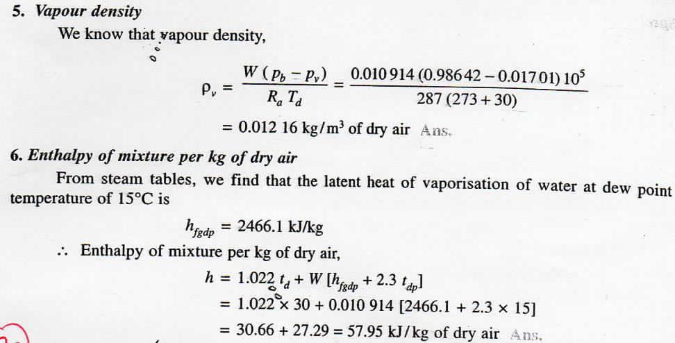
8 td = Dry bulb temperature, and tw = Wet bulb temperature. 5.Vapour density or absolute humidity. We have already discussed that the vapour density or absolute humidity is the mass of water vapour present in 1 m 3 of dry air. Let vv = Volume of water vapour in m 3 /kg of dry air at its partial pressure, va = Volume of dry air in m 3 /kg of dry air at its partial pressure, ρv, = Density of water vapour in kg/m 3 corresponding to its partial pressure and dry bulb temperature td, and ρa = Density of dry air in kg/m 3 of dry air. We know that mass of water vapour,

9 Example.1. The readings from a sling psychrometer are as follows ry bulb temperature = 30 C ; Barometer reading 740mm of Hg Using steam tables, determine : I. Dew point temperature ; 2. Relative humidity ; 3. Specific humidity ; 4. Degree of-saturation ; 5. Vapour density ; and 6. Enthalpy of mixture per kg of dry air. Solution given: td = 30 C ; tw. = 20 C ; P4= 740 mm of Hg 1.Dew point temperature First of all, let us find the partial pressure of water vapour (Pv). From steam tables, we find that the saturation pressure corresponding to wet bulb temperature of 20 C is We know that barometric pressure, Pw = bar ph = 740 mm of Hg... (Given) = 740 x = N/m 2 ( mm of Hg = N/m 2 ) N/m 2 ) = bar. 1 bar = 10 5 Partial pressure of water vapour, Since the dew point temperature is the saturation temperature corresponding to the partial pressure of water vapour (Pv), therefore from steam tables, we find that corresponding to pressure bar, the dew point temperature is 2. Relative humidity tdp = 15 Ans From steam tables, we find that the saturation pressure of vapour corresponding to dry bulb temperature of 30 is We know the relative humidity, Ps = bar
10

11 Example.2: On a particular day, the atmospheric air was found to have a dry bulb temperature of 30 and a wet bulb temperature of 18. The barometric pressure was observed to b 756mm of Hg. Using the tables of psychrometric properties of air, determine the relative humidity, the specific humidity, the dew point temperature, the enthalpy of air per kg of dry air and the volume of mixture per kg of dry air. Solution: Given: td = 30 ; tw - 18 ; Pb = 756 mm of Hg Specific humidity We know that specific humidity, Dew point temperature Since the dew point temperature is the saturation temperature corresponding to the partial pressure of water vapour (Pv), therefore from steam tables, we find that corresponding
12 to 9.62 mm of Hg or 9.62 x = N/m 2 = bar, the dew point temperature is, Enthalpy of air per kg of dry air tdp = 10.6 C Ans. From steam tables, we also find that latent heat of vaporization of water at dew point temperature of 10.6 C, hfgdp = kj/kg We know that enthalpy of air per kg of dry air, h = td + W ( hfgdp tdp) = x ( x 10.6) = = kj/kg of dry air Ans. Volume of the mixture per kg of dry air From psychrometric tables, we find that specific volume of the dry air at 760 mm of Hg and 30 C dry bulb temperature is m 3 /kg of dry air. We know that one kg of dry air at a partial pressure of ( ) mm of Hg occupies the same volume as W = kg of vapour at its partial pressure of 9.62 mm of Hg. Moreover, the mixture occupies the same volume but at a total pressure of 756 mm of Hg. Volume of the mixture (v) at a dry bulb temperature of 30 C and a pressure of 9.62 mm of Hg = Volume of 1 kg of dry air (va) at a pressure of ( ) or mm of Hg Note : The volume of mixture per kg of dry air may be calculated as discussed below : where Ra = Gas constant for air = 287 J/kg K Td = Dry bulb temperature in K = = 303 K, and pa = Pressure of air in N/m 2
13 = Pb - Pv = = mm of Hg = x = N/m 2 Substituting the values in the above equation, Example.3. The humidity ratio of atmospheric air at 28 C dry bulb temperature and 760 mm of mercury is kg / kg of dry air. Determine: 1. partial pressure of Water vapour; 2.relative humidity; 3. dew point temperature; 4. specific enthalpy; and 5. vapour density. Solution: Given: td = 28 C ; Pb = 760 mm of Hg ; W = kg/ kg of dry air 1.Partial pressure of water vapour Let Pv = Partial pressure of water vapour. We know that humidity ratio (W), Pv = Pv or Pv = Pv = 12.16/0.638 = mm of Hg = x = N/m 2 Ans. 2. Relative humidity From steam tables, we find that the saturation pressure of vapour corresponding to dry bulb temperature of 28`C is Relative humidity, Ps = bar = 3778 N/m 2 3. Dew point temperature Since the dew point temperature is the saturation temperature corresponding to the partial pressure of water vapour (Pv), therefore from steam tables, we find that corresponding to a pressure of N/m 2 ( bar), the dew point temperature is, tdp = 21.1 C Ans.
 We know that vapour density, = 1.022 x 28 + 0.016 (2451.76 + 2.3 x 21_1) = 28.62 + 40-68.62 kj/kg of dry air Ans. = 0.0183 kg/m 3")
14 4. Specific enthalpy From steam tables, latent heat of vaporization of water corresponding to a dew point temperature of 21.1 C, We know that specific enthalpy. 5. Vapour density hfgdp = kj/kg h = td + W (hfgdp tdp) We know that vapour density, = x ( x 21_1) = kj/kg of dry air Ans. = kg/m 3 of dry air. 3.5 THERMODYNAMIC WET BULB TEMPERATURE OR ADIABATIC SATURATION TEMPERATURE The thermodynamic wet bulb temperature or adiabatic saturation temperature is the temperature at which the air can be brought to saturation state, adiabatically, by the evaporation of water into the flowing air. Fig.4 Adiabatic saturation of air. The equipment used for the adiabatic saturation of air, in its simplest form, consists of an insulated chamber containing adequate quantity of water. There is also an arrangement for extra water (known as make-up water) to flow into the chamber from its top, as shown in Fig.4.

15 Let the unsaturated air enters the chamber at section 1. As the air passes through the chamber over a long sheet of water, the water evaporates which is carried with the flowing stream of air, and the specific humidity of the air increases. The make-up water is added to the chamber at this temperature to make the water level constant. Both the air and water are cooled as the evaporation takes place. This process continues until the energy transferred from the air to the water is equal to the energy required to vaporize the water. When steady conditions are reached, the air flowing at section 2 is saturated with water vapour. The temperature of the saturated air at section 2 is known as thermodynamic wet bulb temperature or adiabatic saturation temperature. The adiabatic saturation process can be represented on T-s diagram as shown by the curve 1-2 in Fig.5. Fig.5. T-s diagram for adiabatic saturation process During the adiabatic saturation process, the partial pressure of vapour increases, although the total ressure of the air-vapour mixture. The unsaturated air initially at dry bulb temperature td2, is coo e adiabatically to dry bulb temperature td, which is equal to the adiabatic saturation temperature tw. It may be noted that the adiabatic saturation temperature is taken equal to the wet bulb temperature for all practical purposes. Let h1 = Enthalpy of unsaturated air at section 1, W1 = Specific humidity of air at section 1, h2,w2 = Corresponding values of saturated air at section 2, and hfw= Sensible heat of water at adiabatic saturation temperature. Balancing the enthalpies of air at inlet and outlet (i.e. at sections 1 and 2),
 and eliminate lot of calculations.")
16 3.6 PSYCHROMETRIC CHART It is a graphical representation of the various thermodynamic properties of moist air. The psychrometric chart is very useful for finding out the properties of air (which are required in the field of air conditioning) and eliminate lot of calculations. There is a slight variation in the charts prepared by different air-conditioning manufactures but basically they are all alike. The psychrometric chart is normally drawn for standard atmospheric pressure of 760 mm of Hg (or bar). Fig. 6 Psychrometric chart. In a psychrometric chart, dry bulb temperature is taken as abscissa and specific humidity i.e. moisture contents as ordinate, as shown in Fig. 6. Now the saturation curve is

17 drawn by plotting the various saturation points at corresponding dry bulb temperatures. The saturation curve represents 100% relative humidity at various dry bulb temperatures. It also represents the wet bulb and dew point temperatures. Though the psychrometric chart has a number of details, yet the following lines are important frpm the subject point of view : 1. Dry bulb temperature lines. The dry bulb temperature lines are vertical i.e. parallel to the ordinate and uniformly spaced as shown in Fig. 7. Generally the temperature range of these lines on psychrometric chart is from - 6 C to 45 C. The dry bulb temperature lines are drawn with difference of every 5 C and up to the saturation curve as shown in the figure. The values of dry bulb temperatures are also shown on the saturation curve. 2. Specific humidity or moisture content lines. The specific humidity (moisture content) lines are horizontal i.e. parallel to the abscissa and are also uniformly spaced as shown in Fig Generally, moisture content range of these lines on psychrometric chart is from 0 to 30 g / kg of dry air (or from 0 to kg / kg of dry air). The moisture content lines are drawn with a difference of every 1 g (or kg) and up to the saturation curve as shown in the figure. Fig.7. Dry bulb temperature lines. Fig. 8. Specific humidity lines. 3. Dew point temperature lines. The dew point temperature lines are horizontal i.e. parallel to the abscissa and non-uniformly spaced as shown in Fig At any point on the saturation curve, the dry bulb and dew point temperatures are equal. The values of dew point temperatures are generally given along the saturation curve of the chart as shown in the figure.

18 Fig. 9 Dew point temperature lines. Fig.10 Wet bulb temperature lines. 4. Wet bulb temperature lines. The wet bulb temperature lines are inclined straight lines and non-uniformly spaced as shown in Fig.10. At any point on the saturation curve, the dry bulb and wet bulb temperatures are equal. The values of wet bulb temperatures are generally given along the saturation curve of the chart as shown in the figure. 5. Enthalpy (total heat) lines. The enthalpy (or total heat) lines are inclined straight lines and uniformly spaced as shown in Fig.11. These lines are parallel to the wet bulb temperature lines, and are drawn up to the saturation curve. Some of these lines coincide with the wet bulb temperature lines also. The values of total enthalpy are given on a scale above the saturation curve as shown in the figure. 6. Specific volume lines. The specific volume lines are obliquely inclined straight lines and uniformly spaced as shown in Fig.12. These lines are drawn up to the saturation curve. The values of volume lines are generally given at the base of the chart. Fig. 11. Enthalpy lines. Fig. 12. Specific volume lines.

19 7. Vapour pressure lines. The vapour pressure lines are horizontal and uniformly spaced. Generally, the vapour pressure lines are not drawn in the main chart. But a scale showing vapour pressure in mm of Hg is given on the extreme left side of the chart as shown in Fig.13. lines. Fig. 13. Vapour pressure lines. Fig. 14. Relative humidity 8. Relative humidity lines. The relative humidity lines are curved lines and follow the saturation curve. Generally, these lines are drawn with values 10%, 20%, 30% etc. and up to 100%. The saturation curve represents 100% relative humidity. The values of relative humidity lines are generally given along the lines themselves as shown in Fig PSYCHROMETRIC PROCESSES The various psychrometric processes involved in air conditioning to vary the psychrometric properties of air according to the requirement are as follows: 1. Sensible heating, 2. Sensible cooling, 3. Humidification and dehumidification, 4. Cooling and adiabatic humidification, 5. Cooling and humidification by water injection, 6. Heating and humidification, 7. Humidification by steam injection, 8. Adiabatic chemical dehumidification, 9. Adiabatic mixing of air streams. We shall now discuss these psychrometric processes, in detail, in the following pages Sensible Heating The heating of air, without any-change in its specific humidity, is known as sensible heating. Let air at temperature td, passes over a heating coil of temperature td3, as shown in Fig. 15 (a). It may be noted that the temperature of air leaving the heating coil (td2) will be less than td3. The process of sensible heating, on the psychrometric chart, is shown by a horizontal line 1-2 extending from left to right as shown in Fig.15 (b). The point 3 represents the surface temperature of the heating coil. The heat absorbed by the air during sensible heating may be obtained from the psychrometric chart by the enthalpy difference (h2 - h1) as shown in Fig. 15 (b). It may be noted that the specific humidity during the sensible heating remains constant (i.e. W1 = W2).


20 The dry bulb temperature increases from td1, to td2 and relative humidity reduces from 1, to 2 as shown in Fig. 15 (b). The amount of heat added during sensible heating may also be obtained from the relation: Fig.15 Sensible heating Notes: 1. For sensible heating, steam or hot water is passed through the heating coil. The heating coil may be electric resistance coil. 2. The sensible heating of moist air can be done to any desired temperature Sensible Cooling The cooling of air without any change in its specific humidity, is known as sensible cooling. Let air at temperature rd, passes over a cooling coil of temperature td3 as shown in Fig. 16 (a). It may be noted that the temperature of air leaving the cooling coil (td2) will be more than td3. The process of sensible cooling, on the psychrometric chart, is shown by a horizontal line 1-2 extending from right to left as shown in Fig. 16 Fig. 16 Sensible cooling.
21 The heat rejected by air during sensible cooling may be obtained from the psychrometric chart by the enthalpy difference (h1 h,) as shown in Fig. 16(b). It may be noted that the specific humidity during the sensible cooling remains constant (i.e.w1= W2). The dry bulb temperature reduces from td1 to td2 and relative humidity increases from 1 to 2 as shown in Fig. 16(b). The amount of heat rejected during sensible cooling may also be obtained from the relation: Heat rejected, q = hl - h2 = Cpa (td1- td2) + W Cps(td1 - td2) = (Cpa + W Cps) (td1 - td2) = Cpm (td1 - td2) The term (Cpa + W Cps) is called humid specific heat (Cpm) and its value is taken as kj /kg K. Heat rejected, q = (td1 - td2) kj/kg For air conditioning purposes, the sensible heat per minute is given as SH = ma Cpm t=vρ Cpm t kj/min... ( m = vρ) where v = Rate of dry air flowing in m 3 /min, ρ = Density of moist air at 20 C and 50% relative humidity = 1.2 kg / m3 of dry air, Cpm = Humid specific heat = kj /kg K, and t = td1 - td2= Difference of dry bulb temperatures between the entering and leaving conditions of air in C. Substituting the values of p and cp,,, in the above expression, we get SH = v x 1.2 x x t = v x t kj/min 3.73 By-pass Factor of Heating and Cooling Coil The temperature of the air corning out of the apparatus (td2) will be less than *td3 in case the coil is a heating coil and more than td3 in case the coil is a cooling coil. Let 1 kg of air at temperature td1 is passed over the coil having its temperature (i.e. coil surface temperature) td3 as shown in Fig. 17.

22 A little consideration will show that when air passes over a coil, some of it (say x kg) just by-passes unaffected while the remaining (1 - x) kg comes in direct contact with the coil. This by-pass process of air is measured in terms of a by-pass factor. The amount of air that by-passes or the by-pass factor depends upon the following factors : 1. The number of fins provided in a unit length i.e. the pitch of the cooling coil fins ; 2. The number of rows in a coil in the direction of flow; and 3. The velocity of flow of air. It may be noted that the by-pass factor of a cooling coil decreases with decrease in fin spacing and increase in number of rows. Balancing the enthalpies, we get Fig.17. By-pass factor

23 Let the air passes over a heating coil. Since the temperature distribution of air passing through the heating coil is as shown in Fig.18. therefore sensible heat given out by the coil. where U = Overall heat transfer coefficient, Ac = Surface area of the coil, and tm = Logarithmic mean temperature difference. We know that logarithmic mean temperature difference,
 is known as efficiency of coil or contact factor.")
24 Proceeding in the same way as discussed above, we can derive the equation (iv) for a cooling coil. Note: The performance of a heating or cooling coil is measured in terms of a by-pass factor. A coil with low by-pass factor has better performance Efficiency of Heating and Cooling Coils The term (1 - BPF) is known as efficiency of coil or contact factor. Efficiency of the heating coil, Similarly, efficiency of the cooling coil, 3.75 Humidification and Dehumidification The addition of moisture to the air, without change in its dry bulb temperature, is known as humidification. Similarly, removal of moisture from the air, without change in its dry bulb temperature, is known as dehumidification. The heat added during humidification process and heat removed during dehumidification process is shown on the psychrometric chart in Fig. 19 (a) and (b) respectively. Ultrasonic humidification system It may be noted that in humidification, the relative humidity increases from 1 to 2 and specific humidity also increases from W1 to W2 as shown in Fig. 19 (a). Similarly, in dehumidification, the relative humidity decreases from 1 to 2 and specific humidity also decreases from W1 to W2 as shown in Fig. 19 (b).

25 Fig. 19 Humidification and dehumidification It may be noted that in humidification, change in enthalpy is shown by the intercept (h2 - h1) on the psychrometric chart. Since the dry bulb temperature of air during the humidification remains constant, therefore its sensible heat also remains constant. It is thus obvious that the change in enthalpy per kg of dry air due to the increased moisture content equal to (W2 - W1) kg per kg of dry air is considered to cause a latent heat transfer (LH). Mathematically, Multiple small plate dehumidification system LH = (h2 - h1) = hfg (W2 - W1) where hfg is the latent heat of vaporization at dry bulb temperature (tdt). Notes: 1. For dehumidification, the above equation may be written as: LH = (h1 h2) = hfg (W1 - W2) 2. Absolute humidification and dehumidification processes are rarely found in practice. These are always accompanied by heating or cooling processes. 3. In air conditioning, the latent heat load per minute is given as LH = ma h = ma hfg W = v ρ hfg W ( ma = v ρ)
 for humidification and")
26 where v = Rate of dry air flowing in m 3 /min, ρ = Density of moist air = 1.2 kg/m 3 of dry air, hfg = Latent heat of vaporization = 2500 kj /kg, and AW = Difference of specific humidity between the entering and leaving conditions of air = (W2 - W1) for humidification and (W1 W2) for dehumidification. Substituting these values in the above expression, we get LH = v x 1.2 x 2500 x W = 3000 v x W kj/min 3.8 Methods of Obtaining Humidification and Dehumidification The humidification is achieved either by supplying or spraying steam or hot water or cold water into the air. The humidification may be obtained by the following two methods: 1. Direct method. In this method, the water is sprayed in a highly atomized state into the room to be air-conditioned. This method of obtaining humidification is not very effective. 2. Indirect method. In this method, the water is introduced into the air in the airconditioning plant, with the help of an air-washer, as shown in Fig. 20. This -conditioned air is then supplied to the room to be air-conditioned. The air-washer humidification may be accomplished in the following three ways: Fig. 20. Air-washer. (a) by using re-circulated spray water without prior heating of air, (b) by pre-heating the air and then washing if with re-circulated water, and
27 (c) by using heated spray water. The dehumidification may be accomplished with the help of an air-washer or by using chemicals. In the air-washer system the outside or entering air is cooled below its dew point temperature so that it loses moisture by condensation. The moisture removal is also accomplished when the spray water is chilled water and its temperature is lower than the dew point temperature of the entering air. Since the air leaving the air-washer has its dry bulb temperature much below the desired temperature in the room, therefore a heating coil is placed after the air-washer. The dehumidification may also be achieved by using chemicals which have the capacity to absorb moisture in them. Two types of chemicals known as absorbents (such as calcium chloride) and adsorbents (such as silica gel and activated alumina) are commonly used for this purpose. Sensible Heat Factor As a matter of fact, the heat added during a psychrometric process may be split up into sensible heat and latent heat. The ratio of the *sensible heat to the total heat is known us sensible heat factor (briefly written as SHF) or sensible heat ratio (briefly written as SHR). Mathematically, where SH = Sensible heat, and LH = Latent heat. chart. The sensible heat factor scale is shown on the right hand side of the psychrometric 3.9 Cooling and Dehumidification This process is generally used in summer air conditioning to cool and dehumidify the air. The air is passed over a cooling coil or through a cold water spray. In this process, the dry bulb temperature as well as the specific humidity of air decreases. The final relative humidity of the air is generally higher than that of the entering air. The dehumidification of air is only possible wh6n the effective surface temperature of the cooling coil (i.e.td4) is less than the dew point temperature of the air entering the coil (i.e., tdpt.). The effective surface temperature of the coil is known as apparatus dew point (briefly written as ADP). The cooling and dehumidification process is shown in Fig. 21.
 should be equal to the surface temperature of the cooling coil (i.e. ADP), but it is never possible due to inefficiency of the cooling coil.")
28 td1 = Dry bulb temperature of air entering the coil, tdpl = Dew point temperature of the entering air = td3 and td4 = Effective surface temperature or ADP of the coil. Under ideal conditions, the dry bulb temperature of the air leaving the cooling coil (i.e. td4) should be equal to the surface temperature of the cooling coil (i.e. ADP), but it is never possible due to inefficiency of the cooling coil. Therefore, the resulting condition of air coming out of the coil is shown by a point 2 on the straight line joining the points 1 and 4. The by-pass factor in this case is given by Also Actually, the cooling and dehumidification process follows the path as shown by a dotted curve in Fig. 21(a), but for the calculation of psychrometric properties, only end points are important. Thus the cooling and dehumidification process shown by a line 1-2 may be assumed to have followed a path 1-A (i.e. dehumidification) and A-2 (i.e. cooling) as shown in Fig. 21 (a). We see that the total heat removed from the air during the cooling and dehumidification process is q = h1 - h2 = (h1 - ha) + (ha h2) = LH + SH where LH = h1 ha = Latent heat removed due to condensation of vapour of the reduced moisture content (W1 W2), and We know that sensible heat factor, SH = ha h2 = Sensible heat removed.

29 Note: The line 1-4 (i.e. the line joining the point of entering air and the apparatus dew point) in Fig. 21 (b) is known as sensible heat factor line. Example 1: In a cooling application, moist air enters a refrigeration coil at the rate of 100 kg of dry air per minute at 35 C and 50% RH. The apparatus dew point of coil is 5 C and by-pass factor is Determine the outlet state of moist air and cooling capacity of coil in TR. Solution Given: ma = 100 kg/min; tdt = 35 C; = 50%; ADP = 5 C; BPF = 0.15 Outlet state of moist air Let td2, and 2 = Temperature and relative humidity of air leaving the cooling coil. First of all, mark the initial condition of air, i.e. 35 C dry bulb temperature and 50% relative humidity on the psychrometric chart at point 1, as shown in Fig. 22. From the psychrometric chart, we find that the dew point temperature of the entering air at point 1, tdpt = 23 C Since the coil or apparatus dew point (ADP) is less than the dew point temperature of entering air, therefore it is a process of cooling and dehumidification. We know that by-pass factor, Fig.22 From the psychrometric chart, we find that the relative humidity corresponding to a dry bulb temperature (td2,) of 9.5 Con the line 1-4 is 2 = 99%. Ans. Cooling capacity of the coil The resulting condition of the air coming out of the coil is shown by point 2, on the line joining the points 1 and 4, as shown in Fig. 22. The line 1-2 represents the cooling and dehumidification process which may be assumed to have followed the path 1-A (i.e. dehumidification) and A-2 (i.e. cooling). Now from the psychrometric chart, we find that enthalpy of entering air at point 1,
 Example 2. 39.6 m 3 /min of a mixture of re-circulated room air and outdoor air enters cooling coil at 31 C dry bulb temperature and 18.5 C wet bulb temperature.")
30 h1= 81 kj/kg of dry air and enthalpy of air at point 2, h2= 28 kj/kg of dry air We know that cooling capacity of the coil = ma(h1- h2) = 100 (81-28) = 5300 kj/min = 5300/210 = TR Ans..( 1 TR = 210 kj/min) Example m 3 /min of a mixture of re-circulated room air and outdoor air enters cooling coil at 31 C dry bulb temperature and 18.5 C wet bulb temperature. The effective surface temperature of the coil is 4.4 C. The surface area of the coil is such as would give 12.5 kw of refrigeration with the given entering air state. Determine the dry and wet bulb temperatures of the air leaving the coil and the by-pass factor. Solution: Given: v1= 39.6 m 3 /min; tdt = 31 C; twt = I8.5 C; ADP= td4= 4.4 C; Q= 12.5 kw = 12.5 kj/s = 12.5 x 60 kj/min Dry and wet bulb temperature of the air leaving the coil Let td2 and tw2 = Dry and wet bulb temperature of the air leaving the coil. First of all, mark the initial condition of air, i.e. 31 C dry bulb temperature and 18.5 C wet bulb temperature on the psychrometric chart at point 1, as shown in Fig. 23. Now mark the effective surface temperature (ADP) of the coil at 4.4 C at point 4. From the psychrometric chart, we find that enthalpy at point 1 Enthalpy at point 4, Specific humidity at point 1 Specific humidity at point 4, Specific volume at point h1 = 52.5 kj / kg of dry air h4 = 17.7kJ/kg of dry air W1 = kg / kg of dry air W4= kg / kg of dry air vs1, = 0.872m 3 / kg We know that mass flow rate of dry air at point 1,

31 Now plot point 2 on the psychrometric chart such as enthalpy, h2 = kj/kg of dry air and specific humidity, W2 = kg/kg of dry air. At point 2, we find that By-pass factor We know that by-pass factor, td2 = 18.5 C; and tw2 = 12.5 C Ans Heating and Humidification This process is generally used in winter air conditioning to warm and humidify the air. It is the reverse process of cooling and -- dehumidification. When air is passed through a humidifier having spray water temperature higher than the dry bulb temperature of the entering air, the unsaturated air will reach the condition of saturation and thus the air becomes hot. The heat of vaporization of water is absorbed from the spray water itself and hence it gets cooled. In this way, the air becomes heated and humidified. The process of heating and humidification is shown by line 1-2 on the psychrometric chart as shown in Fig. 24. The air enters at condition 1 and leaves at condition 2. In this process, the dry bulb temperature as well as specific humidity of air increases. The final relative humidity of the air can be lower or higher than that of the entering air.
32 Fig.24 heating and humidification Let mw1 and mw2 = Mass of spray water entering and leaving the humidifier in kg, hfw1 and hfw2 = Enthalpy of spray water entering and leaving the humidifier in kj/kg, W1 and W2 = Specific humidity of the entering and leaving air in kg/kg of dry h1 and h2 = Enthalpy of entering and leaving air in kj/kg of dry air, and ma = Mass of dry air entering in kg. For mass balance of spray water, (mw1 mw2) = ma (W2 - W1) mw2 = mw1 - ma (W2 W1). (i) or and for enthalpy balance, mw1 hfw1 = mw2 hfw2 = ma(h2 h1).(ii) Substituting the value of mw2 from equation (i), we have mw1 hfw1 [ mw1 - ma (W2 - W1)] hfw2 = ma (h2 h1) The temperatures ts1 and ts2 shown in Fig. 24 (a) denote the temperatures of entering and leaving spray water respectively. The temperature 13 is the mean temperature of the spray water which the entering air may be assumed to approach. Actually, the heating and humidification process follows the path as shown by dotted curve in Fig. 24(b), but for the calculation of psychrometric properties, only the end points are important. Thus, the heating and humidification process shown by a line 1-2 on the psychrometric chart may be assumed to have followed the path 1-A (i.e. heating) and A-2
33 (i.e. humidification), as shown in Fig. 24(b). We see that the total heat added to the air during heating and humidification is q = h2 h1 = (h2 h1) + (ha - hi) = qt + qs where moisture qt= (h2 - ha) = Latent heat of vaporization of the increased We know that sensible heat factor, content (W2 W1), and qs = (ha - hi) = Sensible heat added Note: The line 1-2 in Fig. 24 (b) is called sensible heat factor line Heating and Humidification by Steam Injection The steam is normally injected into the air in order to increase its specific humidity as shown in Fig. 25 (a). This process is used for the air conditioning of textile mills where high humidity is to be maintained. The dry bulb temperature of air changes very little during this process, as shown on the psychrometric chart in Fig. 25 (b). Let ms = Mass of steam supplied, ma = Mass of dry air entering, Fig.25 heating and humidification by steam injection W1= Specific humidity of air entering, W2 = Specific humidity of air leaving, h1 = Enthalpy of air entering, h2 = Enthalpy of air leaving, and
] Example 3: Atmospheric air at a dry bulb temperature of 16 C and 25% relative humidity passes through a furnace and then through a humidifier, in such a way that the final dry")
34 Now for the mass balance, hs = Enthalpy of steam injected into the air..(i) and for the heat balance,... [From equation (i)] Example 3: Atmospheric air at a dry bulb temperature of 16 C and 25% relative humidity passes through a furnace and then through a humidifier, in such a way that the final dry bulb temperature is 30 C and 50% relative humidity. Find the heat and moisture added to the air. Also determine the sensible heat factor of the-process. Solution: Given: tdt = 16 C; 1 = 25% ; td2 = 30 C; 42 = 50% Heat added to the air First of all, mark the initial condition of air i.e. at 16 C dry bulb temperature and 25% relative humidity on the psychrometric chart at point 1, as shown in Fig Then mark the final condition of air at 30 C dry bulb temperature and 50% relative humidity on the psychrometric chart at point 2. Now locate the point A by drawing horizontal line through point 1 and vertical line through point 2. From the psychrometric chart, we find that enthalpy of air at point 1, h1 = 23 k1/kg of dry air Fig.26 Enthalpy of air at point A, ha = 38 kj/kg of dry air and enthalpy of air at point 2,
35 h2 = 64 la/kg of dry air Heat added to the air = h2- h1= = 41 kj/kg of dry air Ans. Moisture added to the air From the psychrometric chart, we find that the specific humidity in the air at point 1, W1 = kg/kg of dry air and specific humidity in the air at point 2, W2 = kg /kg of dry air Moisture added to the air = W2 W1 = = kg/kg of dry air Ans. Sensible heat factor of the process We know that sensible heat factor of the process, Example 4: Air at 10 C dry bulb temperature and 90% relative humidity is to be ated and humidified to 35 C dry bath temperature and 22.5 C wet bulb temperature. The air is pre-heated sensibly before passing to the air washer in which water is recirculated. The relative humidity of the air coming out of the air washer is 90%. This air is again reheated sensibly to obtain the final desired condition. Find: 1. the temperature to which the air should be preheated. 2. the total heating required; 3. the makeup water required in the air washer ; and 4. the humidifying efficiency of the air washer. Solution: Given : tdt = 10 C; 1 = 90%; td2,=35 C; tw2=22.5 C First of all, mark the initial condition of air i.e. at 10 C dry bulb temperature and 90% relative humidity, on the psychrometric chart at point 1, as shown in Fig Now mark the final condition of air i.e. at 35 C dry bulb temperature and 22.5 C wet bulb temperature at point 2. From point I, draw a horizontal line to represent sensible heating and from point 2 draw horizontal line to intersect 90% relative humidity curve at point B. Now from point B, draw a constant wet bulb temperature line which intersects the horizontal line drawn through point 1 at point A. The line 1-A represents preheating of air, line AB represents humidification and line 8-2 represents reheating to final condition.
36 Fig.27 1.Temperature to which the air should be preheated From the psychrometric chart, the temperature to which the air should be preheated (corresponding to point A) is 4 tda = 32.6 C Ans. 2. Total heating required From the psychrometric chart, we find that enthalpy of,air at point 1. Enthalpy of air at point A, and enthalpy of air at point 2, h1 = 27.2 kj /kg of dry air ha = 51 kj/kg of dry air h2 = 68 kj/kg of dry air We know that heat required for preheating of air and heat required for reheating of air = ha- h1 = = 23.8 kj/kg of dry air = h2- hb= = 17 kj/kg of dry air Total heat required = = 40.8 kj/kg of dry air Ans. 3. Make up water required in the air washer From the psychrometric chart, we find that specific humidity of entering air, W1 = kg /kg of dry air


37 and specific humidity of leaving air, W2 = kg /kg of dry air Make up water required in the air washer = WB - WA = W2 W1 = = kg/kg of dry air Ans. 4. Humidifying efficiency of the air washer From the psychrometric chart, we find that tdb = 19.1 C and tdb = 18 C We know that humidifying efficiency of the air washer, 3.12 Heating and Dehumidification -Adiabatic Chemical Dehumidification This process is mainly used in industrial air conditioning and can also be used for some comfort air conditioning installations requiring either a low relative humidity or low dew point temperature in the room. In this process, the air is passed over chemicals which have an affinity for moisture. As the air comes in contact with these chemicals, the moisture gets condensed out of the air and gives up its latent heat. Due to the condensation, the specific humidity decreases and the heat of condensation supplies sensible heat for heating the air and thus increasing its dry bulb temperature. Fig.28
38 The process, which is the reverse of adiabatic saturation process, is shown by the line 1-2 on the psychrometric chart as shown in Fig. 28. The path followed during the process is along the constant wet bulb temperature line or-constant enthalpy line. The effectiveness or efficiency of the dehumidifier is given as Notes: 1. In actual practice, the process is accompanied with a release of heat called heat of adsorption, which is very large. Thus the sensible heat gain of air exceeds the loss of latent heat and the process is shown above the constant wet bulb temperature line in Fig Two types of chemicals used for dehumidification are absorbents and adsorbents. The absorbents are substances which can take up moisture from air and during this process change it chemically, physically or in both respects. These include water solutions or brines of calcium chloride, lithium chloride, lithium bromide and ethylene glycol. These are used as air dehydrators by spraying or otherwise exposing a large surface of the solution in the air stream. The adsorbents are substances in the solid state which can take up moisture from the air and during this process do not change it chemically or physically. These include silca gel (which is a form of silicon dioxide prepared by mixing fused sodium silicate and sulphuric acid) and activated alumina (which is a porous amorphous form of aluminum oxide). Example 5: Saturated air at 21 C is passed through a drier so that its final relative humidity is 20%. The drier uses silica gel adsorbent. The air is then passed through a cooler until its final temperature is 21 C without a change in specific humidity. Determine : 1. the temperature of air at the end of the drying process; 2. the heat rejected during the cooling process ; 3. the relative humidity at the end of cooling process; 4. the dew point temperature at the end of the drying process ; and 5. the moisture removed during the drying process. Solution: Given: td1, = td3 = 21 C; 2= 20% 1.Temperature of air at the end of drying process First of all, mark the initial condition of air i.e. at 21 C dry bulb temperature upto the saturation curve (because the air is saturated) on the psychrometric chart at point 1, as shown in Fig. 29. Since the drying process is a chemical dehumidification process, therefore-. it follows a path along-the-constant wet bulb temperature or the constant enthalpy line as shown by the line 1-2 in Fig. 29. Now mark the point 2 at relative humidity of 20%. From the psychrometric chart, the temperature at the end of drying process at point 2, td2 = 38.5 C Ans.
39 2. Heat rejected during the cooling process Fig.29 The cooling process is shown by the line 2-3 on the psychrometric chart as shown in Fig.29. From the psychrometric chart. we find that enthalpy of air at point 2. h2 = 61 kj /kg of dry air and enthalpy of air at point 3, h3 = 43 kj/kg of dry air Heat rejected during the cooling process 3. Relative humidity at the end of cooling process = h2 - h3 = = 18 kj/kg of dry air A ns. From the psychrometric chart, we find that relative humidity at the end of cooling process (i.e. at point 3), 3 = 55% Ans. 4. Dew point temperature at the end of drying process From the psychrometric chart, we find that the dew point temperature at the end of the drying process, tdp2 = 11.6 C Ans. 5. Moisture removed during the drying process From the psychrometric chart, we find that moisture in air before the drying process at point 1, W1 = kg/kg of dry air and moisture in air after the drying process at point 2, W2 = kg/kg of dry air
40 Moisture removed during the drying process AIR CONDITIONING SYSTEMS 3.13 Introduction = W, W, = = kg/kg of dry air Ans. The air conditioning is that branch of engineering science which deals with the study of conditioning of air i.e., supplying and maintaining desirable internal atmosphere conditions for human comfort, irrespective of external conditions. This subject, in its broad sense, also deals with the conditioning of air for industrial purposes, food processing storage of food and other materials Factors affecting comfort Air Conditioning The four important factors for comfort air conditioning are discussed as below: 1. Temperature of air: In air conditioning, the control of temperature means the maintenance of any desired temperature within an enclosed space even though the temperature of the outside air is above or below the desired room temperature. This is accomplished either by the addition or removal of heat from the enclosed space as and when demanded. It may be noted that a human being feels comfortable when the air is at 21 C with 56% relative humidity. 2. Humidity of air: The control of humidity of air means the decreasing or increasing of moisture contents of air during summer or winter respectively in order to produce comfortable and healthy conditions. The control of humidity is not only necessary for human comfort but it also increases the efficiency of the workers. In general, for summer air conditioning, the relative humidity should not be less than 60% whereas for winter air conditioning it should not be more than 40%. 3. Purity of air: It is an important factor for the comfort of a human body. It has been noticed that people do not feel comfortable when breathing contaminated air, even if it is within acceptable temperature and humidity ranges. It is thus obvious that proper filtration, cleaning and purification of air is essential to keep it free from dust and other impurities. 4. Motion of air: The motion or circulation of air is another important factor which should be controlled, in order to keep constant temperature throughout the conditioned space. It is, therefore, necessary that there should be equi-distribution of air throughout the space to be air conditioned Air Conditioning System We have already discussed in Art. the four important factors which affect the human comfort. The system which effectively controls these conditions to produce the desired effects upon the occupants of the space is known as an air conditioning system.
41 3.16 Equipments Used in an Air Conditioning System Following are the main equipments or parts used in an air conditioning system: 1. Circulation fan. The main function of this fan is to move air to and from the room. 2. Air conditioning unit. It is a unit which consists of cooling and dehumidifying processes for summer air conditioning or heating and humidification processes for winter air Conditioning. 3. Supply duct. It directs the conditioned air from the circulating fan to the space to be air conditioned at proper point room. 4. Supply outlets. These are grills which distribute the conditioned air evenly in the 5. Return outlets. These are the openings in a room surface which allow the room ait to enter the return duct. 6. Filters. The main function of the filters is to remove dust, dirt and other harmful bacteria from the air Classification of Air Conditioning Systems The air conditioning systems may be broadly classified as follows: 1. According to the purpose (a) Comfort air conditioning system, and (b) Industrial air conditioning system. 2. According to season of the year (a) Winter air conditioning system, (b) Summer air conditioning system, and (c) Year-round air conditioning system. 3. According to the arrangement of equipment (a) Unitary air conditioning system, and (b) Central air conditioning system. In this chapter, we shall discuss all the above mentioned air conditioning systems one by one.

42 3.18 Comfort Air Conditioning System In comfort air conditioning, the air is brought to the required dry bulb temperature and relative humidity for the human health, comfort and efficiency. If sufficient data of the required condition is not given, then it is assumed to be 21 C dry bulb temperature and 50% relative humidity. The sensible heat factor is, generally, kept as following: For residence or private office = 0.9 For restaurant or busy office = 0.8 Auditorium or cinema hall = 0.7 Ball room dance hall etc. = 0.6 The comfort air conditioning may be adopted for homes, offices, shops, restaurants, theatres, hospitals, schools etc. Example 1: An air conditioning plant is required to supply 60 m of air per minute at a DBT of 21 C and 55% RH. The outside air is at DBT of 28 C and 60% RH. Determine the mass of water drained and capacity of the cooling coil. Assume the air conditioning plant first to dehumidify and then to cool the air. Solution: Given v2 = 60 m 3 /min; td2 = 21 C; 2= 55%; tdt = 28 C; 1 = 60% Mass of water drained First of all, mark the initial condition of air at 28 C dry bulb temperature and 60% relative humidity on the 1 h psychrometric chart as point 1, as shown in Fig. 1. Now mark the final condition of air at 21 C dry bulb temperature % and 55% relative humidity as point 2. From the psychrometric chart, we find that Specific humidity of air at point 1, W1 = kg/kg of dry air Specific humidity of air at point 2, W2 = kg / kg of dry air and specific volume of air at point 2, vs2 = m3/ kg of dry air We know that mass of air circulated, Mass of water drained

43 = ma (W1- W2) = 71( ) = kg / min = x 60 = kg / h Ans. Capacity of the cooling coil From the psychrometric chart, we find that Enthalpy of air at point 1, and enthalpy of air at point 2, Capacity of the cooling coil 3.19 Industrial Air Conditioning System h1 = 64.8 kj / kg of dry air h2 = 42.4 kj / kg of dry air = ma (h1- h2) = 71( ) = kj / min = / 210 = 7.57 TR Ans. It is an important system of air conditioning these days in which the inside dry bulb temperature and relative humidity of the air is kept constant for proper working of the machines and for the proper research and manufacturing processes. Some of the sophisticated electronic and other machines need a particular dry bulb temperature and relative humidity. Sometimes, these machines also require a particular method of psychrometric processes. This type of air conditioning system is used in textile mills, paper mills, machine-parts manufacturing plants, tool rooms, photo-processing plants etc. Industrial air-conditioning system Example 2: Following data refers to an air conditioning system to be designed for an industrial

44 process for hot and wet climate: Outside conditions = 30 C DBT and 75% RH Required inside conditions = 20 C DBT and 60% RH The required condition is to be achieved first by cooling and dehumidifying and then by heating. If 20 nil of air is absorbed-by the plant every minute, find : 1. capacity of the cooling coil in tones of refrigeration; 2. capacity of the heating coil in kw; 3. amount of water removed per hour; and 4. By-pass factor of the heating coil, if its surface temperature is 35 C. Solution: Given tdt = 30 C; 1= 75%; td3= 20 C; 3 = 60%; vl = 20 m 3 / min; td4= 35 C 1.Capacity of the cooling coil in tones of refrigeration First of all, mark the initial condition of air at 30 C dry bulb temperature and 75% relative humidity on the psychrometric chart as point 1, as shown in Fig. 2. Then mark the final condition of air at 20 C dry bulb temperature and 60% relative humidity oil the chart as point 3. Fig.2 Now locate the points 2' and 2 on the saturation curve by drawing horizontal lines through points 1 and 3 as shown in Fig. 2. On the chart, the process 1-2' represents the sensible cooling. 2'-2 represents dehumidifying process and 2-3 represents the sensible heating process. From the psychrometric chart, we find that the specific volume of air at point 1. Enthalpy of air at point 1, and enthalpy of air at point 2, vx1 = m3/ kg of dry air h1 = 81.8 kj/kg of dry air h2 = 34.2 kj / kg of dry air
45 We know that mass of air absorbed by the plant, Capacity of the cooling coil = ma (h1 h2) = 22.6 ( ) = kj / min = / 210 = 5.1 TR Ans. 2. Capacity of the heating coil in kw From the psychrometric chart, we find that enthalpy of air at point 3, h3 = 42.6 kj / kg of dry air Capacity of the heating coil = ma (h1 h2) = 22.6 ( ) = Id / min = / 60 = 3.16 kw Ans. 3. Amount of water removed per hour From the psychrometric chart, we find that specific humidity of air at point 1, W1 = kg / kg of dry air and specific humidity of air at point 2, W2= kg / kg of dry air Amount of water removed per hour = ma (W1 - W2) = 22.6 ( ) = kg / min = x 60 = kg / h Ans. 4. By-pass factor of the heating coil We know that by-pass factor, td2, = 12.2 C]... [From psychrometric chart,
.")
46 3.20 Winter Air Conditioning System In winter air conditioning, the air is heated, which is generally -accompanied by humidification. The schematic arrangement of the system is Damper shown in Fig. 3. Fig.3 Winter air conditioning system The outside air flows through a damper and mixes up with the Outside air recirculated air (which is obtained Fan from the conditioned space). The Filter mixed air passes through a filter to remove dirt, dust and other impurities. The air now passes through a preheat coil in order to prevent the possible freezing of water and to control the evaporation of water in the humidifier. After that, the air is made to pass through a reheat coil to bring the, air to the designed dry bulb temperature. Now, the conditioned air is supplied to the conditioned space by a fan. From the conditioned space, a part of the used air is exhausted to the atmosphere by the exhaust fans or ventilators. The remaining part of the used air (known as re-circulated air) is again conditioned as shown in Fig.3. The outside air is sucked and made to mix with re-circulated air, in order to make for the loss of conditioned (or used) air through exhaust fans or ventilation from the conditioned space Summer Air Conditioning System It is the most important type of air conditioning, in which the air is cooled and generally dehumidified. The schematic arrangement of a typical summer air conditioning system is shown in Fig. 4. The outside air flows through the damper, and mixes up with re-circulated air (which is obtained from the conditioned space). The mixed air passes through a filter to remove dirt, dust and other impurities. The air now passes through a cooling coil. The coil has a temperature much below the required dry bulb temperature of the air in the conditioned space. The cooled air passes through a perforated membrane and loses its moisture in the condensed form which is collected in a sump. After that, the air is made to pass through a heating coil which heats up the air slightly. This is done to bring the air to the designed dry bulb temperature and Damper relative humidity.

47 Fig 4 summer air conditioning system Now the conditioned air is supplied to the conditioned space by a fan. From the conditioned space, a part of the used air is exhausted to the atmosphere by the exhaust fans or ventilators. The remaining part of the used air (known as re-circulated air) is again conditioned -as shown in Fig. 4: The outside air is sucked and made-i6 mix with the recirculated air in order to make up for the loss of conditioned (or used) air through exhaust fans or ventilation from the conditioned space. Example 3: The amount of air supplied to an air conditioned hall is 300m 3 /min. The atmospheric conditions are 35 C DBT and 55% RH. The required conditions are 20 C DBT and 60% RH. Find out the sensible heat and latent heat removed from the air per minute. Also find sensible heat factor for the system. Solution: Given v1 = 300 m 3 /min; tdt, = 35 C ; 1 = 55%; td2 = 20 C; 2 = 60% First of all, mark the initial condition of air at 35 C dry bulb temperature and 55% relative humidity on the psychrometric chart at point 1, as shown in Fig. 5. Now mark the final condition of air at 20 C dry bulb temperature and 60% relative humidity on the chart as point 2. Locate point 3 on the chart by drawing horizontal line through point 2 and vertical line through point 1. From the psychrometric chart, we find that specific volume of air at point 1, Mass of air supplied, Sensible heat removed from the air vs1 = 0.9 m 3 /kg of dry air From the psychrometric chart, we find that enthalpy of air at point 1, h1= 85.8 kj/kg of dry air
 = 5066.2 kj/min Ans. Latent heat removed from the air We know that latent heat removed from the air, LH = ma (h1 - h3) = 333.3 (85.8-57.4) = 9465.7 kj/min Ans.")
48 Fig.5 Enthalpy of air at point 2, h2 = 42.2 kj/kg of dry air and enthalpy of air at point 3, h3 = 57.4 kj/kg of dry air We know that sensible heat removed from the air, SH = ma (h3 - h2) = ( ) = kj/min Ans. Latent heat removed from the air We know that latent heat removed from the air, LH = ma (h1 - h3) = ( ) = kj/min Ans. Sensible heat factor for the system We know that sensible heal factor for the system, Example 4: An air handling unit in an air conditioning plant supplies a total of 4500 m 3 /min of dry air which comprises by mass 20% of fresh air at 40 C DBT and 27 C WBT and 8,%, re-circulated air at 25 C DBT and 50% RH. The air leaves the cooling coil at 13 C saturated. Calculate the total cooling load and room heat gain. The following data can be used:

49 Condition DBT WBT RH Sp. Humidity Enthalpy % % of water vapour Kg of dry air kj/kg of dry air Outside Inside ADP Specific volume of air entering the cooling coil is m 3 / kg of dry air. Solution: Given v3= 4500 m 3 /min; tdt, = 40 C; = 27 C; td2, = 25 C; 2 = 50%; td4= ADP = 13 C; W 1 = 17.2 g / kg of dry air = kg/kg of dry air; W2 = 10g / kg of dry air =0.01 kg/kg of dry air; W4=9.4g/kg of dry air = kg/kg of dry air; h1=85 kj/kg of dry air; h2 = 51 kj/kg of dry air; h4 = 36.8 kj/kg of dry air ; vs3 = ni3/kg of dry air. First of all, mark the condition of fresh air at 40 C dry bulb temperature and 27 C wet bulb temperature on the psychrometric chart as point 1, as shown in Fig. 6. Now mark the condition of re-circulated air at 25 C dry bulb temperature and 50% relative humidity as point 2. The condition of air entering the cooling coil *(point 3) is marked on the line 1-2, such that the specific volume of air at this point is m 3 /kg of dry air. The point 4 represents the condition of air leaving the cooling coil at 13 C on the saturation curve. Fig.6 From the psychrometric chart, we find that enthalpy of air entering the cooling coil at point 3, h3 = 57.8 kj / kg of dry air Specific humidity of air entering the cooling coil at point 3, W3 = kg / kg of dry air
50 and dry bulb temperature of air entering the cooling coil at point 3, td3 = 28.3 C Total cooling load We know that mass of air entering the cooling coil, Total cooling load = ma3 (h3 - h4) = 5178 ( :8) = kj / min Room heat gain = / 210 = TR Ans. Since the total mass of air (ma, = 5178 kg / min) comprises 20% of fresh air, therefore mass of fresh air supplied at point 1. ma1 = 0.2 x 5178 = kg / min and fresh air load = ma1 (h1 h2) = (85 51) = la / min = / 210 = 168 TR Ans. Room heat gain = Total cooling load Fresh air load = = TR Ans. Example 5: A conference room of 60 seating capacity is to be air conditioned for comfort conditions of 22 C dry bulb temperature and 55% relative humidity. The outdoor conditions are 32 C dry bulb temperature and 22 C wet bulb temperature. The quantity of air supplied is 0.5m 3 /min/person. The comfort conditions are achieved first by chemical dehumidification and by cooling coil. Determine I. Dry bulb temperature of air at exit of dehumidifier; 2. Capacity of dehumidifier; 3. Capacity and surface temperature of cooling coil, if the by-pass factor is Solution: Given: Seating capacity = 60; td2= 22 C; 2 = 55%; tdt = 32 C; twt = 22 C; = 0.5 m 3 /min / person = 0.5 x 60 = 30 m 3 /min; BPF = 0.3. First of all, mark the outdoor conditions of air re. at 32 C dry bulb temperature and 22 C wet bulb temperature on the psychrometric chart as point 1, as shown in Fig Now mark the required comfort conditions of air i.e. at 22 C dry bulb temperature and 55% relative humidity, as point 2. In order to find the condition of air leaving the dehumidifier, draw a constant wet bulb temperature line from point 1 and a constant specific humidity linefrom point 2. Let these two lines intersect at point 3. The line 1-3 represents the chemical dehumidification and the line 3-2 represents sensible cooling.
51 Fig.7 1. Dry bulb temperature of air at exit of dehumidifier From the psychrometric chart, we find that dry bulb temperature of air at exit of dehumidifier i.e. at point3, td3 = 41 C Ans. 2. Capacity of dehumidifier From the psychrometric chart, we find that enthalpy of air at point 1, Enthalpy of air at point 2, Specific humidity of air at point 1, Specific humidity of air at point 3, and specific volume of air at point 1, We know that mass of air supplied, hl = = 64.5 kj/kg of dry air h2 = 45 kj / kg of dry air W1 = kg / kg of dry air W3 = W2 = kg/kg of dry air vs1 = m3/ kg of dry air Capacity of the dehumidifier
52 = ma (W1 - W3) = (0: ) = kg / min = x 60 = kg / h Ans. 3. Capacity and surface temperature of cooling coil We know that capacity of the cooling coil = ma (h3 - h2) = ( ) = 664 kj/min = 664 / 210 = 3.16TR Ans.... ( 1TR = 210 kj/min) Let td4 = Surface temperature of the cooling coil. We know that by-pass factor (BPF), Example 6: The following data refer to air conditioning of a public hall: Outdoor conditions = 40 C DBT, 20 C WBT Required comfort conditions = 20 C DBT, 50% RH Seating capacity of hall = 1000 Amount of outdoor air supplied = 0.3 m 3 /min/person If the required condition is achieved first by adiabatic humidifying and then cooling, find: 1. The capacity of the cooling coil and surface temperature of the coil if the by-pass factor is 0.25; and 2. The capacity of the humidifier and its efficiency. Solution: Given tdt = 40 C; tw1 = 20 C; td2 = 20 C; 2 = 50%; Seating capacity = 1000; v1 = 0.3 m 3 /min/person = 0.3 x 1000 = 300 m3/min; BPF = 0.25 Fig.8
53 First of all, mark the outdoor conditions of air i.e., at 40 C dry bulb temperature and 20 C wet bulb temperature on the psychrometric chart as point 1, as shown in Fig. 8. Now mark the required comfort conditions of air i.e. at 20 C dry bulb temperature and 50% relative humidity, as point 2. From point 1, draw a constant wet bulb temperature line and from point 2 draw a constant specific humidity line. Let these two lines intersect at point 3. The line 1-3 represents adiabatic humidification and the line 3-2 represents sensible cooling. From the psychrometric chart, we find that specific volume of air at point 1, Mass of air supplied, vs1, = m 3 / kg of dry air 1. Capacity of the cooling coil and surface temperature of the coil From the psychrometric chart, we find that enthalpy of air at point 3, h3 = 57.6 k)1 kg of dry air Enthalpy of air at point 2, h2 = 39 / kg of dry air Dry bulb temperature of air after humidification i.e., at point 3. td3 = 38 C We know that capacity of the cooling coil kj/min = ma (h3 - h2) = ( ) = 6227 = 6227 / 210 = 29.6 TR Ans. Let td4 = Surface temperature of the coil We know that by-pass factor (BPF),
 = 334.8 (0.")

54 2. Capacity of the humidifier and its efficiency From the psychrometric chart, we find that specific humidity at point 1, W1 = kg / kg of dry air Specific humidity at point 3, W3 = 0:0074 kg / kg of dry air and dry bulb temperature at point 5, td5 = 20 C We know that capacity of the humidifier = ma (W3 - W1) = ( ) = kg / min = x 60 = 20.1 kg / h Ans. and efficiency of the humidifier, 3.22 Year-Round Air Conditioning System The year-round air conditioning system should have equipment for both the summer and winter air conditioning. The schematic arrangement of a modern summer year-round air conditioning system is shown in Fig.9. Fig.9 Year-round air conditioning system The outside air flows through the damper and mixes up with the Damper re-circulated air (which is obtained from the conditioned space). The mixed air passes through a filter to remove dirt, dust and other impurities. In summer air conditioning, the cooling coil operates
55 to cool the air to the desired value. The dehumidification is obtained by operating the cooling coil at a temperature lower than the dew point temperature (apparatus dew point). In winter, the cooling coil is made inoperative and the heating coil operates to heat the air. The spray type humidifier is also made use of in the dry season to humidify the air. Example 7: An air conditioning plant is to be designed for a small office for winter conditions with the following data: Outdoor conditions Required indoor conditions Amount of air circulation = 10 C DBT and 8 C WBT = 20 C DBT and 60% RH = 0.3 m 3 /min/person Seating capacity of the office = 50 persons The required condition is achieved first by heating and then by adiabatic humidifying. Find: I. Heating capacity of the coil in kw and the surface temperature, if the by-pass factor of the coil is 0.32 and 2. capacity of the humidifier. Fig.10 Solution: Given tdt, = 10 C; twl = 8 C; td2 = 20 C; 2= 60%; seating capacity = 50 persons; v1 = 0.3 m 3 /min/person = 0.3 x 50 = 15 m 3 /min; BPF = 0.32 First of all, mark the initial condition of air at 10 C dry bulb temperature and 8 C wet bulb temperature on the psychrometric chart as point 1, as shown in Fig Now mark the final condition of air at 20 C dry bulb temperature and 60% relative humidity on the chart as point 2. Now locate point 3 on the chart by drawing horizontal line through point I and constant enthalpy line through point 2, From the psychrometric chart, we find that the specific volume at point 1, Mass of air supplied per minute, vsl = 0.81 m 3 /kg of dry air
56 1. Heating capacity of the coil in kw and the surface temperature From the psychrometric chart, we find that enthalpy at point 1, h1 = 24.8 kj / kg of dry air and enthalpy at point 2, h2= 42.6 kj / kg of dry air We know that heating capacity of the coil = ma (h2 - h1) = ( ) = kj/min = /60 = 5.5 kw Ans. Let td4 = Surface temperature of the coil. We know that by-pass factor (BPF), td3, = 27.5 C].[From psychrometric chart, or 0.32 (td4 10) = td or 0.32 td4 3.2 = td td4 = 24.3 / 0.68 = 35.7 C Ans. 2. Capacity of the humidifier From the psychrometric chart, we find that specific humidity at point 1, Wl = kg / kg of dry air and specific humidity at point 2, W2 = kg / kg of dry air We know that capacity of the humidifier, min = ma (W2 - W1) = ( ) = kg / = x 60 = 3.3 kg / h Ans. Example 8: A small office hall of 25 person capacity is provided with summer air conditioning system with the following data: Outside conditions Inside conditions = 34 C DBT and 28 C WBT = 24 C DBT and 50% RH
57 Volume of air supplied Sensible heat load in room = 0.4 m3 / min / person = k / h Latent heat load in the room = kj / h Find the sensible heat factor of the plant. Solution: Given Seating capacity = 25 persons; tdt = 34 C; twl = 28 C; td2, = 24 C ; 2 = 50% ; v1 = 0.4 m 3 /min/person = 0.4 x 25 = 10 m3/min; S.H. load = kj / h; L.H. load = kj / h Fig.11 First of all, mark the initial condition of air at 34 C dry bulb temperature and 28 C wet bulb temperature on the psychrometric chart as point 1, as shown in Fig Now mark the final condition of air at 24 C dry bulb temperature and 50% relative humidity on the chart as point 2. Now locate point 3 on the chart by drawing horizontal line through point 2 and vertical line through point 1. From the psychrometric chart, we find that specific volume at point 1, Enthalpy of air at point 1, Enthalpy of air at point 2, and enthalpy of air at point 3, vs1 = 0.9 m3/ kg of dry air h1 = 90 kj / kg of dry air h2 = 48 ld / kg of dry air h3 = 58 / kg of dry air We know that mass of air supplied per min,
58 and sensible heat removed from the air = ma (h3 - h2) = 11.1(58-48) = 111 kj / min = 111 x 60= 6660 kj/h Total sensible heat of the room, SH = = kj / h We know that latent heat removed from the air = ma (h1 - h3) = 11.1(90-58) = 355 kj / min = 355 x 60 = kj / h Total latent heat of the room, LH = =63300 kj / h We know that sensible heat factor, Example 9: A restaurant with a capacity of 100 persons is to be air-conditioned with the following conditions: Outside conditions Desired inside conditions Quantity of air supplied : 30 C DBT and 70% RH : 23 C DBT and 55% RH : 0.5 rn3 / min / person The desired conditions are achieved by cooling, dehumidifying and then heating. Determine: I. Capacity of cooling coil in tones of refrigeration; 2. Capacity of heating coil; 3. Amount of water removed by dehumidifier; and 4. By-pass factor of the heating coil if its surface temperature is 35 C. Solution: Given: Number of persons = 100; tdt = 30 C; 1 = 70%; td4 = 23 C; 4 = 55% ; vl = 0.5 m 3 / min / person = 0.5 x 100 = 50 m 3 /train First of all, mark the outside conditions of air at 30 C dry bulb temperature and 70% relative humidity on the psychrometric chart as point 1, as shown in Fig Now mark the desired inside conditions of air at 23 C dry bulb temperature and 55% relative humidity on the chart as point 4. The process 1-2 represents the sensible cooling, process 2-3 represents dehumidification and the process 3-4 represents the sensible heating. From the psychrometric chart, we find that the specific volume at point 1. vs1 = m 3 /kg of dry air
59 Mass of air supplied, Fig Capacity of cooling coil in tones of refrigeration From the psychrometric chart, we find that enthalpy of air at point 1, h1= 78.5 kj/kg of dry air Enthalpy of air at point 3, h3 = 37.8 kj/kg of dry air Capacity of the cooling coil = ma (h1- h3) = 56.5 ( ) = 2300 kj/min = 2300 / 210 = TR Ans. 2. Capacity of heating coil From the psychrometric chart, we find that enthalpy of air at point 4, h4 = 47.6 kj / kg of dry air Capacity of the heating coil = ma (h4 h3) = 56.5 ( ) = 554 kj/min = 554 / 60 = 9.23 kw Ans. 3. Amount of water removed by dehumidifier From the psychrometric chart, we find that specific humidity at point 2,
 = 0.525 kg I min = 0.525 x 60 = 31.5 kg / h Ans. 4. Let td5 = Surface temperature of the heating coil = 35 C.")
60 and specific humidity at point 3, W2 = kg / kg of dry air W3 = kg / kg of dry air Amount of water removed by dehumidifier 4. By-pass factor of the heating coil = ma (W2 - W3) = 56.5 ( ) = kg I min = x 60 = 31.5 kg / h Ans. 4. Let td5 = Surface temperature of the heating coil = 35 C..(Given) From the psychrometric chart, we find that dry bulb temperature at point 3, td3 = 13.5 C Air conditioning system We know that by-pass factor of the heating coil, Room Sensible Heat Factor It is defined as the ratio of the room sensible heat to the room total heat. Mathematically, room sensible heat factor, where RSH = Room sensible heat,
.")
61 RLH = Room latent heat, and RTH = Room total heat. The conditioned air supplied to the room must have the capacity to take up simultaneously both the room sensible heat and room latent heat loads. The point S on the psychrometric chart, as shown in Fig , represents the supply air condition and the point R represents the required final condition in the room (i.e., room design condition). The line SR is called the room sensible heat factor line (RSHF line). The slope of this line gives the ratio of the room sensible heat (RSH) to the room latent heat (RLH). Thus the supply air having its conditions given by any point on this line will satisfy the requirements of the room with adequate supply of such air. In other words, the supply air having conditions marked by points S1, S2, S3, S4 etc., will satisfy the requirement but the quantity of air supplied will be different for different supply air points. The supply condition at S requires minimum air and at point 54, it is maximum of all the four points. Fig. 13. Representation of supply air condition and room design condition. When the supply air conditions are not known, which in fact is generally required to be found out, the room sensible heat factor line may be drawn from the calculated value of room sensible heat factor (RSHF), as discussed below: 1. Mark point a on the sensible heat factor scale given on the right hand corner of the psychrometric chart as shown-in Fig.14. The point a represents the calculated value of RSHF.
62 Fig. 14 Room sensible heat factor (RSHF) line. 2. Join point a with the *alignment circle or the reference point b. The line ab is called base line. 3. Mark point R on the psychrometric chart to represent the room design conditions. 4. Through point R draw a line RR' parallel to the base line ab. This line is the required room sensible heat factor line. Note: In a cooling and dehumidification process, the temperature at which the room sensible heat factor line intersects the saturation curve is called room apparatus dew point (ADP) Grand Sensible Heat Factor It is defined as the ratio of the total sensible heat to the grand total heat which the cooling coil or the conditioning apparatus is required to handle. Mathematically, grand sensible heat factor, where TSH = Total sensible heat = RSH + OASH TLH = Total latent heat = RLH + OALH GTH = Grand total heat = TSH + TLH = RSH + RLH + OATH = RSH + RLH + (DASH + OALH) Let v1 = Volume of outside air or ventilation in m 3 /min, td1 = Dry bulb temperature of outside air in C, W1 = Specific humidity of outside air in kg / kg of dry air, hi = Enthalpy of outside air in kj / kg of dry air, td2 = Dry bulb temperature of room air in C, W2 = Specific humidity of room air in kg / kg of dry air, and h2 = Enthalpy of room air in kj / kg of dry air. Outside air sensible heat, OASH = v1 (td1- td2) kw
 kw Generally, the air supplied to the air conditioning plant is a mixture of fresh air (or outside air or ventilation) and the re-circulated air having the properties of room air.")
63 Outside air latent heat, and outside air total heat, OALH = 50 v1 (W1 - W2) kw OATH = OASH + OALH The outside air total heat may also be calculated from the following relation: OATH = 0.02 v1(h1 h2) kw Generally, the air supplied to the air conditioning plant is a mixture of fresh air (or outside air or ventilation) and the re-circulated air having the properties of room air. On the psychrometric chart, as shown in Fig. 15, the point 1 represents the outside condition of air, the point 2 represents the room air condition and the point 3 represents the mixture condition of air entering the cooling coil. When the mixture condition enters the cooling coil or conditioning apparatus, it is cooled and dehumidified. The point 4 shows the supply air or leaving condition of air from the cooling coil or conditioning apparatus. When the point 3 is joined with the point 4, it gives a grand sensible heat factor line (GSHF line) as shown in Fig. 5. This line, when produced up to the saturation curve, gives apparatus dew point (ADP). Fig.15 Grand sensible heat factor If the mixture condition entering the cooling coil or conditioning apparatus and the grand sensible heat factor (GSHF) are known, then the GSHF line may be drawn on the psychrometric chart in the similar way as discussed for RSHF line. The point 4, as shown in Fig. 15, is the intersection of GSHF line and RSHF line. This point gives the ideal conditions for supply air to the room Effective Room Sensible Heat Factor It is defined as the ratio of the effective room sensible heat to the effective room total heat. Mathematically, effective room sensible heat factor, Where ERSH = Effective room sensible heat = RSH + OASH x BPF
64 = RSH v1 (tdt td2) BPF ERLH = Effective room latent heat = RLH + OALH x BPF = RLH + 50 v1 (W1 - W2) BPF ERTH = Effective room total heat = ERSH + ERLH BPF = By-pass factor Fig. 16. Effective room sensible heat factor. The line joining the point 2 and point 6 i.e. ADP, as shown in Fig , gives the effective room sensible heat factor line (ERSHF line). From point 4, draw 4.4' parallel to 3-2. Therefore from similar triangles 6-4-4' and 6-3-2, The by-pass factor is also given by, Notes:1. The effective room sensible heat (ERSH), effective room latent heat (ERLH) and effective room total heat (ERTH) may also be obtained from the following relations: ERSH = vd(td2 - ADP) (1 - BPF) kw ERLH = 50 vd (W2 - WADP) (1 - BPF) kw and where ERTH = 0.02 vd(h2 hadp) (1 - BPF) kw vd = Volume of dehumidified air to room or space in m 3 /min,
65 ADP = Apparatus dew point in C, and WADP = Specific humidity at apparatus dew point in kj / kg of dry air, hadp = Enthalpy at apparatus dew point in kj / kg of dry air. 2. The mass of dehumidified air is given by where h2 = Enthalpy of air at room condition, and h4 = Enthalpy of supply air to room from the cooling coil. Example 10: In an air conditioning system, the inside and outside conditions are dry bulb temperature 25 C, relative humidity 50% and dry bulb temperature 40 C, wet bulb temperature 27 C respectively. The room sensible heat factor is % of the room air is rejected to atmosphere and an equal quantity of fresh air added before air enters the air conditioning apparatus. If the fresh air added is 100 m 3 /min, determine: 1. Room sensible and latent heat load; 2. Sensible and latent heat load due to fresh air; 3. Apparatus dew point; 4. Humidity ratio and dry bulb temperature of air entering air conditioning apparatus. Assume by-pass factor as zero, density of air as 1.2 kg / m 3 at a total pressure of bar. Solution: Given tdt = 40 C; tw1, = 27 C; td2= 25 C; 2 = 50% ; RSHF= 0.8; v1 = 100 m 3 /min; ρa =1.2 kg/m 3 The flow diagram for the air conditioning system is shown in Fig. 17, and it is represented on the psychrometric chart as discussed below: First of all, mark the outside condition of air at 40 C dry bulb temperature and 27 C wet bulb temperature on the psychrometric chart as point 1, as shown in Fig. 18. Now mark the inside condition of air at 25 C dry bulb temperature and 50% relative humidity as point 2. Since 50% of the room air and 50% of fresh air is added before entering the air conditioning apparatus, therefore mark point 3 on the line 1-2 such that
.")
66 Fig.17 Now mark the given value of RSHF (i.e. 0.8) on the room sensible heat factor scale and join this with the alignment circle (i.e. 26 C DBT and 50% RH). From point 2, draw a line 2-4 parallel to this line. This line is called RSHF line. The point 4 represents the apparatus dew point (ADP). From the psychrometric chart, we find the enthalpy of air at point 1, Enthalpy of air at point 2, and enthalpy of air at point 4, 1. Room sensible and latent heat load h1= 85.2 kj / kg of dry air We know that mass of air supplied to the room, ma = v3 x ρa = ( )1.2 = 240 kg/min Room sensible heat load, RSH = ma Cpm (td2 - td4) h2 = 50 kj / kg of dry air h4 = 33 kj / kg of dry air = 240 x ( ) = 3238 kj / min td4 = 11.8 C] = 3238/60 = kJ/s or kw [ From psychrometric chart, and room total heat load, RTH = ma (h2 h4) = 240 (50-33) = 4080 kj/min = 4080/60 = 68 kj/s or kw Room latent heat load,
 = 120 x 1.")
67 RLH = RTH - RSH = = kw 2. Sensible and latent heat load due to fresh air We know that mass of fresh air supplied, mf = v1 x ρa = 100 x 1.2 = 120 kg / min Sensible heat load due to fresh air and total heat load due to fresh air Latent heat load due to fresh air 3. Apparatus dew point Fig.18 = mf Cpm (td1 - td2) = 120 x (40-25) = 1840 kj/min = 1840 / 60 = kj/s or kw Ans. = mf (h1- h2) = 120 ( ) = 4224 kj/min = 4224 / 60 = 70.4 kj/s or kw = Total heat load Sensible heat load = = kw Ans. From the psychrometric chart, we find that apparatus dew point (ADP) corresponding to point 4 is
68 td4 = 11.8 C Ans. 4. Humidity ratio and dry bulb temperature of air entering air conditioning apparatus The air entering the air conditioning apparatus is represented by point 3 on the psychrometric chart as shown in Fig. 18. From the psychrometric chart, we find that humidity ratio corresponding to point 3, W3 = kg / kg of dry air Ans. and dry bulb temperature corresponding to point 3. td4= 32.5 C Ans. Example 11: An air conditioned space is maintained at 27 C dry bulb temperature and 40% relative humidity. The ambient conditions are 40 C dry bulb temperature and 27 C wet bulb temperature. The space has a sensible heat gain of 14kW. The air is supplied to the space at 7 C saturated. Calculate: 1. Mass of moist air supplied to the space in kg / h; 2. Latent heat gain of space in kw; and 3. Cooling load of air-washer in kw if 30 per cent of air supplied to the space is fresh, the remainder being re-circulated. Solution: Given td2=.27 C; 2 = 50%; tdt = 40 C; tw1 = 27 C; Qs = 14 kw = 14 kj/s = 14x3600 kj/ h; td4 = 7 C Fig. 19 The line diagram for the air conditioned space is shown in Fig. 19 and it is represented on the psychrometric chart as discussed below: First of all, mark the ambient (outside) conditions of air at 40 C dry bulb temperature and 27 C wet bulb temperature on the psychrometric chart as point 1, as shown in Fig. 20. Now mark the inside conditions of the space at 27 C dry bulb temperature and 50% relative humidity. Since the air is supplied to the space at 7 C saturated, therefore mark point 4 on the saturation curve at 7 C. Also 30 per cent of air supplied to the space (i.e. at point 2) is fresh, therefore mark point 3 on the line 2-1, such that

69 Length 2-3 = 0.3 x Length 2- I Fig.20 Now from the psychrometric chart, we find that enthalpy of air at point 1, h1= 85 kj / kg of dry air Specific humidity of air at point 1, W1= kg / kg of dry air Enthalpy of air at point 2, h2 = 56 kj / kg of dry air Specific humidity of air at point 2, W2 = kg / kg of dry air Enthalpy of air at point 4, h4 =23 kj / kg of dry air Specific humidity of air at point 4, W4 = kg / kg of dry air 1. Mass of moist air supplied to the space in kg / h We know that mass of dry air supplied to the space,. [ Cpm = Humid specific heat = kj / kg K]
70 Mass of moist air supplied to the space, 2. Latent heat gain of space in kw We know that latent heat gain of space, 3. Cooling load of air-washer in kw = ma (1 + W4) = ( ) = 2481 kg / h Ans. QL = ma (W2 - W4) hfg = ( ) 2500 = kj/h = / 3600 = 8.56 kj/s or kw Ans. From the psychometric chart, we find that dry bulb temperature of air at point 3, and enthalpy of air at point 3, *td3 = 31 C h3 = 64.6 kj / kg of dry air We know that cooling load of air-washer = ma (h3 - h4) = ( ) = kj/h = / 3600 = 28.5 k-j/s or kw Ans Example 12: Air flowing at the rate of 100m 3 /min at 40 C dry bulb temperature and 50% relative humidity is mixed with another stream flowing at the rate of 20m 3 /min at 26 C dry: bulb temperature and 50% relative humidity. The mixture flows over a cooling coil whose apparatus dew point temperature is 10 C and by-pass factor is 0.2. Find dry bulb temperature and relative humidity of air leaving the coil. If this air is supplied to an airconditioned room where dry bulb temperature of 26 C and relative humidity of 50% are maintained, estimate 1. Room sensible heat factor; and 2. Cooling load capacity of the coil in tones of refrigeration Solution: Given v1 =100 m 3 /min; tdt = 40 C; 1 = 50%; v2 = 20 m 3 /min ; td2 = 26 C ; 2 = 50% ; ADP =10 C ; BPF = 0.2 The flow diagram for an air-conditioned room is shown in Fig 21 and it is represented on the psychrometric chart as discussed below: First of all, mark the initial condition of air at 40 C dry bulb temperature and 50% relative humidity on the psychrometric chart as point 1, as shown in Fig. 22. Now mark the room condition of air at 26 C dry bulb temperature and 50% relative humidity as point 2. From the psychrometric chart, we find that enthalpy of air at point 1,
71 h1 = 99.8 kj / kg of dry air Enthalpy of air at point 2, h2 = 53.5 Id / kg of dry air Specific volume of air at point 1, vs1= 0.92 m3/ kg of dry air and specific volume of air at point 2, vs2 = m 3 / kg of dry air We know that mass of air supplied at point 1, Fig,21
72 Fig.22 and mass of air supplied at point 2, Mass of air flowing through the cooling coil at point 3. ma3 = mal + ma2 = = kg / min For the energy balance, ma1h1 + ma2 h2 = ma3 h3 = kj / kg of dry air Now draw a constant enthalpy line corresponding to h3 = k7 / kg of dry air which intersects the line 1-2 at point 3. From the psychrometric chart, we find that dry bulb temperature of air entering the cooling coil at point 3 is td3 = 37.6 C
73 Mark point 5 on the saturation curve such that ADP = 10 C, and draw a line 3-5. The point 4 lies on this line. Dry bulb temperature and relative humidity of air leaving the coil Let td4 = Dry bulb temperature of air leaving the coil. We know that by-pass factor (BPF), td4 = C Ans. From the psychrometric chart, we find that relative humidity of air leaving the coil at point 4 is 1. Room sensible heat factor 4 = 92% Ans. From the psychrometric chart, we find that enthalpy of air at point 4, h h4 = 42 kj / kg of dry air. and enthalpy of air at point A (which is the intersection of horizontal line from point 4 and vertical line from point 2), ha = 52.5 kj / kg of dry air We know that room sensible heat factor, 2. Cooling load capacity of the coil We know that cooling load capacity of the coil Ans = ma3 (h3- h4) = ( ) = kj/min = / 210 = TR Ans. ( 1 TR= 210 1J/min) Example 13: An air conditioned auditorium is to be maintained at 27 C dry bulb temperature and 60 % relative humidity. The ambient condition is 40 C dry bulb temperature and 30 C wet bulb temperature. The total sensible heat load is kj/h and the total latent heat load is kj/h. 60% of the return air is re-circulated and mixed with 40% of make-up air after the cooling coil. The condition of air leaving the cooling coil is at 18 C.
74 Determine: 1. Room sensible heat factor; 2. The condition of air entering the auditorium; 3. The amount of make-up air; 4. Apparatus dew point; and 5. By-pass factor of the cooling coil. Show the processes on the psychrometric chart. Solution: Given td4 =27 C; 4 = 60%; tdt, = 40 C; tw1= 30 C; RSH= kJ / h; RLH = kj / h; td2 = 18 C 1. Room sensible heat factor We know that room sensible heat factor, 2. Condition of air entering the auditorium The line diagram for processes involved in the air conditioning of an auditorium is shown in Fig. 23. These processes are shown on the psychrometric chart as discussed below : Fig.23 First of all, mark the ambient condition of air (outside air) i.e. at 40 C dry bulb temperature and 30 C wet bulb temperature on the psychrometric chart as point 1, as shown in Fig Now mark the condition of air in the auditorium, i.e. at 27 C dry bulb temperature and 60% relative humidity, as point 4. Mark the calculated value of RSHF = on the sensible heat factor scale as point a and join with point b which is the alignment circle (i.e. 26 C DBT and 50% RH) as shown in Fig. 24. Now from point 4, draw a line 4-5 (known as RSHF line) parallel to the line ab. Since the condition of air leaving the cooling coil is at 18 C, therefore, mark point 2 such that td2= 18 C. Join points 1 and 2 and produce up to point 6 on the saturation curve. The line is the GSHF line. It is given that 60% of the air from the auditorium is re-circulated and mixed with 40% of the make-up air after the cooling coil. The mixing condition of air is shown at point such that

75 The condition of air entering the auditorium is given by point 3. From the psychrometric chart, we find that at point 3, Dry bulb temperature, td3 = 23 C Ans. Wet bulb temperature, tw3= 19.5 C Ans. and relative humidity, 3 = 72% Ans. 3. Amount of make-up air From the psychrometric chart, we find that enthalpy of air at point 4, h4 = 61 kj/kg of dry air and enthalpy of air at point 3, h3 = 56 kj/kg of dry air Fig.24 We know that mass of supply air to the auditorium, Since the make-up air is 40% of supply air, therefore mass of make-up air 4. Apparatus dew point = 0.4 x = kg / h Ans. From the psychromettic chart, we find that the apparatus dew point of the cooling coil at point 6 is
76 ADP = td6= 13 C Ans By-pass factor.of the coaling coil We know that by-pass factor of the cooling coil, Example 14: An air conditioned hall is to be maintained at 27 C dry bulb temperature and 21 C wet bulb temperature. It has a sensible heat load of 46.5 kw and latent heat load of 17.5 kw. The air supplied from outside atmosphere at 38 C dry bulb temperature and 27 C wet bulb temperature is 25m 3 /min, directly into the room through ventilation and infiltration. Outside air to be conditioned is passed through the cooling coil whose apparatus dew point is 15 C. The quantity of re-circulated air from the hall is 60%. This quantity is mixed with the conditioned air after the cooling coil. Determine : 1. condition of air after the coil and before the re-circulated air mixes with it; 2. condition of air entering the hall, i.e. after mixing with re-circulated air; 3. mass of fresh air entering the cooler; 4. by-pass factor of the cooling coil: and 5. refrigerating load on the cooling coil. Solution: Given td4 = 27 C; tw4 = 21 C; Qs4 = 46.5 kw; QL4 = 17.5 kw; tdt, = 38 C; tw1= 27 C ; v1 = 25m 3 /min; ADP = 15 C The line diagram for the processes involved in the air conditioning of a hall is shown in Fig These processes are shown on the psychrometric chart as discussed below: Fig. 25 First of all, mark the condition of outside air i.e. at 38 C dry bulb temperature and 27 C wet bulb temperature on the psychrometric chart as point 1, as shown in Fig Now mark the condition of air in the hall, i.e. at 27 C dry bulb temperature and 21 C wet bulb temperature, at point 4. Mark point A by drawing vertical and horizontal lines from
77 points 1 and 4 respectively. Since 25 m3/min of outside air at Id, = 38 C and tw1 = 27 C is supplied directly into the room through ventilation and infiltration, therefore the sensible heat and latent heat of 25 m 3 /min infiltrated air are added to the hall in addition to the sensible heat load of 46.5 kw and latent heat load of 17.5 kw. Fig.26 From the psychrometric chart, we find that enthalpy of air at point 1, h1= 85 kj/kg of dry air Enthalpy of air at point 4 H4= 61 kj/kg of dry air and enthalpy of air at point A, ha= 72.8 kj / kg of dry air Also specific volume of air at point 1, vs1, = m 3 / kg of dry air Mass of air infiltrated into the hall, Sensible heat load due to the infiltrated air, Qs1 = ma (ha - h4) = ( ) = kj/min = /60 = 5.42 kw and latent heat load due to the infiltrated air, QL1 = ma (h1 - ha) = ( ) = kj/min
78 = /60 = 5.6 kw Total room sensible heat load, RSH = Qs4 + Qs1 = = kw and total room latent heat load RLH = QL4+ QL1= = 23.1 kw We know that room sensible heat factor, Now mark this calculated value of RSHF on the sensible heat factor scale and join with the alignment circle (i.e. 26 C DBT and 50% RH) as shown in Fig. 26. From point 4, draw a line 4-5 (known as RSHF line) parallel to this line. Since the outside air marked at point 1 is passed through the cooling coil whose ADP = 15 C, therefore join point 1 with ADP = 15 C on the saturation curve. This line is the GSHF line and intersects the RSHF line at point 2, which represents the condition of air leaving the cooling coil. Also 60% of the air from the hall is re-circulated and mixed with the conditioned air after the cooling coil. The mixing condition of air is shown at point 3 such that 1. Condition of air after the coil and before the re-circulated air mixes with it The condition of air after the coil and before the re-circulated air mixes with it is shown by point 2 on the psychrometric chart, as shown in Fig. 26. At point 2, we find that Dry bulb temperature, td2 = 19 C Ans. Wet bulb temperature, tw2 = 17.5 C Ans. 2. Condition of air entering the hall, i.e. after mixing with re-circulated air The condition of air entering the hall, i.e. after mixing with re-circulated air, is shown by point 3 on the psychrometric chart, as shown in Fig. 26. At point 3, we find that Dry bulb temperature, td3 = 24 C Ans. Wet bulb temperature, tw3= 19.8 C Ans. 3. Mass of fresh air entering the cooler The mass of fresh air passing through the cooling coil to take up the sensible and latent heat of the hall is given by
 = 375(85 49) = 13 500 kj/min = 13 500/210 = 64.3 TR Ans.")
79 ... (From psychrometric chart, h2 = 49 kj / kg of dry air) 4. By-pass factor of the cooling coil We know that by-pass factor of the cooling coil, 5. Refrigerating load on the cooling coil We know that the refrigerating load on the cooling coil = mf (h1- h2) = 375(85 49) = kj/min = /210 = 64.3 TR Ans. Example 15: The room sensible and latent heat loads for an air conditioned space are kw and 5 kw respectively. The room condition is 25 C dry bulb temperature and 50% relative humidity. The outdoor condition is 40 C dry bulb temperature and 50% relative humidity. The ventilation requirement is such that on mass flow rate basis 20% of fresh air is introduced and 80% of supply air is re-circulated. The by-pass factor of the cooling coil is Determine: I. supply airflow rate; 2. outside air sensible heat; 3. outside air latent heat; 4. grand total heat; and 5. effective room sensible heat factor. Solution: Given RSH = 25kW; RLH = 5kW; td2= 25 C; 2 = 50%; tdt = 40 C; 1 = 50%; BPF = 0.15 The flow diagram for the air conditioned space is shown in Fig and it is represented on the psychrometric chart as discussed below: Fig.27
80 First of all, mark the initial condition of air at 40 C dry bulb temperature and 50% relative humidity on the psychrometric chart as point 1, as shown in Fig. 28. Now mark the room, condition of air at 25 C dry bulb temperature and 50% relative humidity as point 2. We know that i room sensible heat factor, Fig. 28 Now mark this calculated value of RSHF=0.833 on the sensible heat factor scale as point a and join with point b which is the alignment circle (i.e. 26 C dry bulb temperature and 50% relative humidity). From point 2, draw a line 2-5 parallel to the line ab. The line 2-5 is called RSHF line. Since 20% of fresh or outside air is mixed with 80% of supply air, therefore the condition of air entering the cooling coil after mixing process is marked on the line 1-2 by point 3, such that Length 2-3 = Length 1-2 x 0.2 Through point 3,-draw a line 3-6 (known as GSHF line) intersecting the RSHF line at point 4 and the saturation curve at point 6, such that 1. Supply air flow rate Let v = Supply air flow rate in m3/min, td4 =Dry bulb temperature of air leaving the cooling coil, and td6 = Apparatus dew point (ADP).
81 From the psychrometric chart, we find that dry bulb temperature of air entering the cooling coil at point 3, We know that by-pass factor (BPF) td3 = 28 C By trial and error, we find that td4 = C and td6 = 11.2 C We know that room sensible heat load, RSH = v (td2 - td4) 25 = v ( ) = 0.23 v v = 25 /0.23 = m3/min Ans. 2. Outside air sensible heat Since the outside air is 20% of the supply air, therefore outside air flow rate, v0 = 0.2 v = 0.2 x = m 3 /min We know that outside air sensible heat, OASH = v0 (tdt - td2) = x (40-25) = 6.66 kw Ans. 3. Outside air latent heat From the psychrometric chart, we find that specific humidity of outside air at point 1, W1 = kg / kg of dry air and specific humidity of room air at point 2, W2 = kg / kg of dry air We know that outside air latent heat, OALH = 50 v0 (W1 - W2) = 50 x ( ) = 15 kw Ans. 4. Grand total heat We know that total sensible heat,
82 TSH = RSH + OASH = = kw and total latent heat, TLH = RLH + OALH = = 20 kw Grand total heat, GTH = TSH + TLH = = kw Ans. Note: The total sensible heat (TSH) and total latent heat (TLH) may also be calculated as follows: From psychrometric chart, we find that specific humidity at point 3, and specific humidity at point 4. We know that total sensible heat, W3 = kg / kg of dry air W4 = kg / kg of dry air TSH = v (td3 td4) and total latent heat, TLH = 50 v (W3 - W4) 5. Effective room sensible heat factor We know that effective room sensible heat, = x ( ) = 31.7 kw = 50 x ( ) = 20.1 kw ERSH = RSH + OASH x BPF = x 0.15 = 26 kw
83 3.25 COMFORT CONDITIONS 3.26 Introduction Strictly speaking, the human comfort depends upon physiological and psychological condition. Thus it is difficult to defang the term human comfort. There are many definitions given for this term by different bodies. But the most accepts definition, from the subject point of view, is given by the American Society of Heating, Refrigeration and air Conditioning Engineers (ASHRAE) which states : human comfort is that conditions of mind, which expressed satisfaction with the thermal environment 3.27 Thermal Exchanges of Body with Environment The human body works best at a certain temperature, like any other machine, but it cannot tolerate wide range of variations in their environment temperatures like machines. The human body maintains its thermal equilibrium with the environment by means of three modes of hat transfer i.e evaporation, radiation and convection. The way in which the individual s body maintains itself in comfortable equilibrium will be by its automatic use of one or more of the three models of heat transfer. A human body feels comfortable when the heat produced by metabolism of human body is equal to the of the heat dissipated to the surroundings and the heat stared inhuman body by rising the temperature of body tissues. This phenomenon may be represented by the following equation. It may be noted that 1. The metabolic heat produced (QM) depends upon the rate of food energy consumption in the body. A fasting, weak or sick man, will have less metabolic heat production. 2. The heat loss by evaporation is always positive. It depends upon the vapour pressure difference between the skin surface and the surrounding air. The heat loss of evaporation (QE) is given by QE = Cd A (Ps Pv) hfg CC Cd = Diffusion coefficient in kg of water evaporated per Unit surface area and pressure difference per hour. A = Skin surface area = 1.08 m2 for normal man, Ps = Saturation vapour pressure corresponding to skin temperature Pv = Vapour pressure of surrounding air, Hf8 = Latent heat of vaporization = 2450 kj/kg, Cc = Factor which accounting for clothing worn.
84 The value of QE becomes zero when Ps = Pc, i.e when the surrounding air temperature is equal to the skin temperature and air is saturated or when it is higher than the erature and the air is nearly saturated. The skin tempplus sing is used when heat is lost to the surrounding and negative sing is used when heat is gained from surroundings. The plus sign is used when the temperature of the body rises and negative sign is used when the temperature of the body falls. The value of Qe is never negative as when p s is less than p v, the skin will not absorb moisture from the surrounding air as it is in sutures state. The only way for equalizing the pressure difference is by increasing p s to p v by rise of skin temperature from the sensible heat flow from air skin. 3. The heat loss or gain by radiation (QR) from the body to the surroundings depends upon the mean radiant temperature. It is the average surface temperature of the surrounding object when properly weighted, and varies from place to place inside the room. When the mean radiant temperature is lower the day bulb temperature of air in the room, QR is positive i.e the body will undergo a radiant heat loss. On the other hand, if the mean radiant temperature is higher than will undergo radiant heat loss. On the other hand, if the mean radiant temperature is higher than the dry bulb temperature of air in the room, QR is negative i.e the body will undergo a radiant heat gain.
85 4. The heat loss by convection (QC) from the body to the surroundings is given by where QC = UA (tb-ts) U = Body film coefficient of heat transfer, A = Body surface area = 1.8 m2 for normal man, Tb = Temperature of the body, and Ts = Temperature of the surroundings. When the temperature of the surroundings (ts) is higher than the temperature of the body (tb), then QC will be negative, i.e the heat will be gained by the body. On the other hand if the temperature of the surroundings (ts) is lower than the temperature of the body (TB), then QC will be the positive, i,e the heat will be lost by the body. Since the body film coefficient of heat transfer increases with the increase in air velocity, therefore higher air velocities will produce uncomforted t when Ts is higher than tb. The higher air velocities are recommended when ts is lower than tb. 5. When QE, QR and QC are high and positive and (QE + QR + QC) is greater than (QM-W), the heat stored in the body (Qs) will be negative i.e the body temperature falls sown. Thus the sick, weak, old or a fasting man feels colder. On the other a man gets fever when high internal body actives increases QM to such extent so that QS becomes positive for the given QE, QR and QC. The heat stored in the body has maximum and minimum limits which when exceed bring death. The usual body temperature, for a normal man (when Qs =0) is 37 C (98.6 F). the temperature of the body temperature of the body when falls below 36.5 C (98 F) and exceeds 40.5 C (105 F) is dangerous. There is some kind of thematic control called vasomotor control mechanism in the human body which maintains the temperature of body at the normal level of 37 C, by regulating the blood supply to the skin. When the temperature of the body falls (i.e the heal stored QS in the body is negative), then the vasomotor control decreases the circulation of blood which decreases conductivity of never cells and other tissues between the skin and the inner body cells. This allows temperature to fall but allows higher inner temperature of body cells beneath. When the temperature of the body rises (i.e the heat stared Qs in the body is positive), then the vasomotor control increases blood circulation which increases conductivity of tissues and hence allows less temperature drop between the skin and inner body cell. The human body feels comfortable when there is no changes in the body temperature, i.e when the heat stored in the body Qs is zero. Any variation in the body temperature acts as a stress to the brain which ultimately results in either perspiration or shivering Physiological Hazards Resulting from Heat In summer the temperature of the surrounding is always higher than temperature of the body. Thus the body will gin heat from the surrounding by means of radiation and convection processes. The body can dissipate eat only through evaporation of sweat. When the health loss by evaporation in unable to cope with the heat gain, there will bestrgae of heat in the body and the temperature of body rises. Several physiological hazards exist, the
86 severity of which depends upon the extent and time duration of body temperature rise. Following are some of the physiological hazards which may result due to the rise in body temperature. 1. Heat exhaustion. It is due to the failure of normal blood circulation. The symptoms of heat exhaustion ileuses fatigue, headache, dizziness, vomiting and abnormal mental reaction such as irritability, severe heat exhaustion may close fainting. It does not cause permanent injury to the body and recovery is usually rapid when the person is removed to a cool places. 2. Heat cramp. It results from loss of salt due to an excessive rate of body perspiration. It cases sever pain in the calf and thing muscles. The heat cramp may be largely avoided by using salt tablets. 3. Heat stroke. It is most serious hazarded, when man is exposed to excessive heat and work, the body temperature may rise rapidly to 40.5 C (105 F) or higher. At such elevated temperatures, sweating cease and the man may enter a soma, with death imminent. A person experiencing a hat stroke may have permanent damage to the brain. The heat stroke may be avoided by taking sufficient water at frequent intervals. It has been found that man doing hard work in the sun requires one liter of water per hour Factors Affecting Human Comfort In designing winter or summer air conditioning system, the designer should be well conversant with a number of factors which physiologically affect human comfort. The important farces are as follows: 1. Effective temperature, 2. Heat production and regulation in human body 3. Heat and moister losses from the human body, 4. Moisture content of air, 5. Quality and quantity of air. 6. Air motion, 7. Hot and cold surfaces and 8. Air stratification These factors are discussed, in detail, in the following articles: Effective Temperature The degree of warmth or cold felt by a human body depends mainly on the following three factors: 1. Dry bulb temperature, 2. Relative humidity and 3. Air velocity. In order to evaluate the combined effect of these factors, the effective temperature is employed. It is defined as that index which collates the com binned effects of air temperature, relative humidity and air velocity on the human body. The numerical value of effective temperate is made equal to the temperature of stills (i.e 5 to 8 m/min air velocity) saturated air, which produces the same sensation of warmth or clones as produced under the given conditions. The practical application of the concept of effective temperature is presented by the comfort chart, as shown in Fig 171. This chart is the result of research made on different kinds of people subjected to wide range of environmental temperature, relative humidity and air movement by the American Society of Heating, Refrigeration and Air conditioning Engineers (ASHRAE). It is appreciable to reasonably still air (5 to 8 m/min air velocity) to

87 situations where the occupants are seated at rest or doing light work and to space whose enclosing surfaces are at a mean temperature equal to the air dry bulb temperature. In the comfort chart, as shown in Fig.17.1, the dry bulb temperature is taken as abscissa and the wet bulb temperature of ordinates. The relative humidity lines are repotted from the psychometric chart. The statistically prepared graphs corresponding to summer and winter season are also superimposed. These graphs have effective temperature scale as abscissa and % of people feeling comfortable as ordinate. A close study of the chart reveals that the several combination of wet and dry bulb temperatures with different relative humidity will produces the same effective temperature. However, all points located on a given effective temperature line do not indicate conditions of equal comfort or discomfort. The extremely high or low relative humidifies may process conditions of discomfort repulses or existent effective temperate. The moist deniable relive humidly rages lies between 30 and 70 per cent. When the relative humidity is much below 30 per cent, the mucous membranes and the skin surface become too dry for comfort and health. On the other hand, if the relative humidity is above 70 per cent, there is a tendency for a clammy or sticky sensation to develop. The curves at the top and bottom, as shown in Fig. 17.1, indicate the parentages of person participating in tests, who found various effective temperatures satisfactory for comfort. The comfort chart shows the range for both summer and winter condition within which a condition of comfort exists for most people. For summer conditions, the chart indicates that a maximum of 98 percent people felt comfortable for an effective temperature of 21.6 C. For winter conditions, chart indicates that an effective temperature of 20 C was desired by 97.7 percent people. It has been found that comfort; women require 0.5 C higher effect give temperature than men. All men and women above 40 years of age preset 0.5 Chiger effective temperature than the person below 40 years of age.
UNIT - 3 Refrigeration and Air - Conditioning
 UNIT - 3 Refrigeration and Air - Conditioning Science of providing and maintaining temperatures below that of surroundings I n t r o d u c t i o n t o R e f r i g e r a t i o n The term refrigeration may
Thermodynamics II Chapter 6 Mixtures & Psychrometry
 Thermodynamics II Chapter 6 Mixtures & Psychrometry Mohsin Mohd Sies Fakulti Kejuruteraan Mekanikal, Universiti Teknologi Malaysia Objectives Differentiate between dry air and atmospheric air. Define and
Institute of Aeronautical Engineering (Autonomous) Dundigal, Hyderabad B.Tech (III II SEM) MECHANICAL ENGINEERING
 Dundigal, Hyderabad B.Tech (III II SEM) MECHANICAL ENGINEERING") Institute of Aeronautical Engineering (Autonomous) Dundigal, Hyderabad- 500 043 B.Tech (III II SEM) MECHANICAL ENGINEERING REFRIGERATION AND AIR CONDITIONING Prepared by, Dr. CH V K N S N Moorthy, Professor
Institute of Aeronautical Engineering (Autonomous) Dundigal, Hyderabad- 500 043 B.Tech (III II SEM) MECHANICAL ENGINEERING REFRIGERATION AND AIR CONDITIONING Prepared by, Dr. CH V K N S N Moorthy, Professor
s. Properties for R134a are as follows : Saturated R-134a Superheated R-134a
 CHAPTER 9 REFRIGERATION & AIR-CONDITIONING YEAR 2012 ONE MARK Common Data For Q. 1 and Q.2 A refrigerator operates between 120 kpa and 800 kpa in an ideal vapour compression cycle with R-134a as the refrigerant.
For an ideal gas mixture, Dalton s law states that the sum of the partial pressures of the individual components is equal to the total pressure.
 1 PSYCHROMETICS Psychrometry is the study of the characteristics of moist air. We will see soon that evaporation of moisture from the skin can have a significant impact on thermal comfort. The rate of
Dhulapally, Secunderabad Subject: REFRIGERATION AND AIR CONDITIONING QUESTION BANK
 St.MARTIN S ENGINEERING COLLEGE Dhulapally, Secunderabad-500 014 Subject: REFRIGERATION AND AIR CONDITIONING Class : ECE III 1 Define Unit of refrigeration. 2 Define C.O.P. QUESTION BANK 3 What is the
AND AIR-CONDITIONING. Dr Ali Jawarneh Department of Mechanical Engineering Hashemite University
 Chapter 14 GAS VAPOR MIXTURES AND AIR-CONDITIONING Dr Ali Jawarneh Department of Mechanical Engineering Hashemite University 2 Objectives Differentiate between dry air and atmospheric air. Define and calculate
ME 410 MECHANICAL ENGINEERING SYSTEMS LABORATORY MASS & ENERGY BALANCES IN PSYCHROMETRIC PROCESSES EXPERIMENT 3
 ME 410 MECHANICAL ENGINEERING SYSTEMS LABORATORY MASS & ENERGY BALANCES IN PSYCHROMETRIC PROCESSES EXPERIMENT 3 1. OBJECTIVE The objective of this experiment is to observe four basic psychrometric processes
R07. Answer any FIVE Questions All Questions carry equal marks *****
 Set No: 1 III B.Tech. II Semester Supplementary Examinations, April/May 2013 REFRIGERATION AND AIR CONDITIONING (Mechanical Engineering) Time: 3 Hours Max Marks: 80 Answer any FIVE Questions All Questions
SIDDHARTH GROUP OF INSTITUTIONS :: PUTTUR Siddharth Nagar, Narayanavanam Road AUTONOMOUS QUESTION BANK (DESCRIPTIVE) UNIT I
 UNIT I") SIDDHARTH GROUP OF INSTITUTIONS :: PUTTUR Siddharth Nagar, Narayanavanam Road 517583 AUTONOMOUS QUESTION BANK (DESCRIPTIVE) Subject with Code : Refrigeration and Air Conditioning (16ME8806) Course & Branch:
SIDDHARTH GROUP OF INSTITUTIONS :: PUTTUR Siddharth Nagar, Narayanavanam Road 517583 AUTONOMOUS QUESTION BANK (DESCRIPTIVE) Subject with Code : Refrigeration and Air Conditioning (16ME8806) Course & Branch:
UNIT 1 AIR CONDITIONING 1. Write the various psychometric processes? Explain any four processes with neat sketches?
 SIDDHARTH INSTITUTE OF ENGINEERING & TECHNOLOGY :: PUTTUR (AUTONOMOUS) (Approved by AICTE, New Delhi & Affiliated to JNTUA, Anantapuramu) (Accredited by NBA & Accredited by NAAC with A Grade) (An ISO 9001:2008
ME 410 MECHA ICAL E GI EERI G SYSTEMS LABORATORY
 ME 410 MECHA ICAL E GI EERI G SYSTEMS LABORATORY MASS & E ERGY BALA CES I PSYCHROMETRIC PROCESSES EXPERIME T 3 1. OBJECTIVE The object of this experiment is to observe four basic psychrometric processes
ME Mechanical Engineering Systems Laboratory. Experiment 3 - Mass and Energy Balances in Psychrometric Processes
 ME 410 - Mechanical Engineering Systems Laboratory Experiment 3 - Mass and Energy Balances in Psychrometric Processes Assist.Prof.Dr. Özgür BAYER, A-123 AIR-CONDITIONING (A/C) Goal: Control temperature
INSTITUTE OF AERONAUTICAL ENGINEERING
 1 P a g e INSTITUTE OF AERONAUTICAL ENGINEERING (Autonomous) Dundigal, Hyderabad -00 043 MECHANICAL ENGINEERING QUESTION BANK Name : REFRIGERATION AND AIR CONDITIONING Code : A60334 Class : III B. Tech
Chapter 14 GAS VAPOR MIXTURES AND AIR-CONDITIONING
 Thermodynamics: An Engineering Approach, 6 th Edition Yunus A. Cengel, Michael A. Boles McGraw-Hill, 2008 Chapter 14 GAS VAPOR MIXTURES AND AIR-CONDITIONING Mehmet Kanoglu Copyright The McGraw-Hill Companies,
 MECHANICAL DEPARTMENT, OITM SEM: 6 TH REFRIGERATION & AIR-CONDITIONING PAPER: ME-302-E UNIT-I Q.1 (a) Derive an expression for the COP of Bell-Coleman refrigeration cycle in terms of pressure. (10) [May-09]
SIR C.R.REDDY COLLEGE OF ENGINEERING, ELURU DEPARTMENT OF MECHANICAL ENGINEERING ETD-II. Model Short Answer Questions And Answers
 SIR C.R.REDDY COLLEGE OF ENGINEERING, ELURU DEPARTMENT OF MECHANICAL ENGINEERING ETD-II Model Short Answer Questions And Answers VAPOUR POWER CYCLES 1. What are the methods to increase thermal efficiency
Psychrometrics. Outline. Psychrometrics. What is psychrometrics? Psychrometrics in daily life and food industry Psychrometric chart
 Psychrometrics Outline What is psychrometrics? Psychrometrics in daily life and food industry Psychrometric chart Dry bulb temperature, wet bulb temperature, absolute humidity, relative humidity, specific
Week 4. Gas-vapor mixtures Air conditioning processes. ME 300 Thermodynamics II 1
 Week 4 Gas-vapor mixtures Air conditioning processes ME 300 Thermodynamics II 1 Today s Outline Gas-vapor mixtures Key definitions and measures ME 300 Thermodynamics II 2 Gas-vapor Mixtures At temperatures
HVAC (Heating, Ventilating, and Air Conditioning)
") HVAC (Heating, Ventilating, and Air Conditioning) Gas vapor Mixtures The term vapor implies a gaseous state that is close to the saturation region of the substance, raising the possibility of condensation
HVAC (Heating, Ventilating, and Air Conditioning) Gas vapor Mixtures The term vapor implies a gaseous state that is close to the saturation region of the substance, raising the possibility of condensation
R10. IV B.Tech I Semester Regular/Supplementary Examinations, Nov/Dec REFRIGERATION & AIR-CONDITIONING (Mechanical Engineering)
") Set No. 1 IV B.Tech I Semester Regular/Supplementary Examinations, Nov/Dec - 2014 REFRIGERATION & AIR-CONDITIONING (Mechanical Engineering) Time: 3 hours Max. Marks: 75 Answer any FIVE Questions All Questions
Set No. 1 IV B.Tech I Semester Regular/Supplementary Examinations, Nov/Dec - 2014 REFRIGERATION & AIR-CONDITIONING (Mechanical Engineering) Time: 3 hours Max. Marks: 75 Answer any FIVE Questions All Questions
Department of Mechanical Engineering ME 322 Mechanical Engineering Thermodynamics
 Department of Mechanical Engineering ME 3 Mechanical Engineering Thermodynamics Lecture 34 The Psychrometric Chart Psychrometric Properties in EES Air Conditioning Processes Moist Air Properties Using
FS 231: Final Exam (5-6-05) Part A (Closed Book): 60 points
 Part A (Closed Book): 60 points") Name: Start time: End time: FS 231: Final Exam (5-6-05) Part A (Closed Book): 60 points 1. What are the units of the following quantities? (10 points) a. Enthalpy of a refrigerant b. Dryness fraction of
Name: Start time: End time: FS 231: Final Exam (5-6-05) Part A (Closed Book): 60 points 1. What are the units of the following quantities? (10 points) a. Enthalpy of a refrigerant b. Dryness fraction of
Thermo-physical properties found on most psychrometric charts
 Psychrometric Chart The psychrometric chart displays the relationship between dry-bulb, wet-bulb, and dew point temperatures and specific and relative humidity. Given any two properties, the others can
S.A. Klein and G.F. Nellis Cambridge University Press, 2011
 12.A-1 A mixture of helium and water vapor is flowing through a pipe at T= 90 C and P = 150 kpa. The mole fraction of helium is y He = 0.80. a.) What is the relative humidity of the mixture? b.) What is
Chapter 14. At temperatures below the critical temperature, the gas GAS VAPOR MIXTURES AND AIR-CONDITIONING. Objectives
 Chapter 14 GAS VAPOR MIXTURES AND -CONDITIONING At temperatures below the critical temperature, the gas phase of a substance is frequently referred to as a vapor. The term vapor implies a gaseous state
MECHANICAL ENGINEERING THERMAL AND FLUID SYSTEMS STUDY PROBLEMS
 MECHANICAL ENGINEERING THERMAL AND FLUID SYSTEMS STUDY PROBLEMS MASS BALANCES, PSYCHROMETRICS & HVAC 1 Copyright 2018. All rights reserved. How to use this book The exam specifications in effect since
: REFRIGERATION & AIR CONDITIONING COURSE CODE : 6023 COURSE CATEGORY : A PERIODS/ WEEK : 6 PERIODS/ SEMESTER : 90 CREDIT : 6 TIME SCHEDULE
 COURSE TITLE : REFRIGERATION & AIR CONDITIONING COURSE CODE : 6023 COURSE CATEGORY : A PERIODS/ WEEK : 6 PERIODS/ SEMESTER : 90 CREDIT : 6 TIME SCHEDULE MODULE TOPIC PERIODS 1 Introduction. Applications
Pressure Enthalpy Charts
 Pressure Enthalpy Charts What is a p-h Diagram? A p-h diagram is a diagram with a vertical axis of absolute pressure and a horizontal axis of specific enthalpy. "Enthalpy is the amount of energy in a substance
The Basics - B Practical Psychrometrics. Jerry Cohen President Jacco & Assoc.
 The Basics - B Practical Psychrometrics Jerry Cohen President Jacco & Assoc. Who is Jacco Established 1968 Hudson, Ohio Columbus, Ohio Toledo, Ohio Focused on the Engineered Environment Systems Knowledgeable
UNIT-1 Q.1 Draw P-V and T-s diagram of Reversed Carnot cycle (2M-Apr./May-2009) Q.2 Define Ton of refrigeration and COP. (2M- Nov/Dec-2009)
 Q.2 Define Ton of refrigeration and COP. (2M- Nov/Dec-2009)") UNIT-1 Q.1 Draw P-V and T-s diagram of Reversed Carnot cycle (2M-Apr./May-2009) Q.2 Define Ton of refrigeration and COP. (2M- Nov/Dec-2009) (2M-Apr./May-2011) Q.3 Differentiate between heat engine and
UNIT-1 Q.1 Draw P-V and T-s diagram of Reversed Carnot cycle (2M-Apr./May-2009) Q.2 Define Ton of refrigeration and COP. (2M- Nov/Dec-2009) (2M-Apr./May-2011) Q.3 Differentiate between heat engine and
LISTOF EXPERIMENTS. S. No. NAME OF EXPERIMENTS PAGE No.
 LISTOF EXPERIMENTS S. No. NAME OF EXPERIMENTS PAGE No. 1. To study refrigeration cyc;e, determine of coefficient of performance of cycle & determine of tonnage capacity of refrigeration unit. 2. To determine
Psychrometrics: The Science of Moisture in Air. Presented by Tom Peterson, CEO and Founder. Climate by Design International
 Psychrometrics: The Science of Moisture in Air Presented by Tom Peterson, CEO and Founder Climate by Design International www.cdihvac.com Owatonna, MN 507-451-2198 4 02/2014 1 Psychrometrics or psychrometry
118 ELEM EN TS OF HEAT EN GIN ES Vol. Ill moisture to the air, as is necessary during the winter, and removing moisture from air during summer, in
 3 AIR CONDITIONING 3.1 Introduction Air conditioning may be defined as the simultaneous control of temperature, humidity (moisture content), motion of air, (movement and circulation), and purity (filtering
THE PSYCHROMETRIC CALCULATOR By: Stanley F. Gallos, The Bastian-Blessing Company INTRODUCTION PROPERTIES OF THE RSES CALCULATOR
 Source Application Manual SAM Chapter 620-20 Section 03 THE PSYCHROMETRIC CALCULATOR By: Stanley F. Gallos, The Bastian-Blessing Company INTRODUCTION Problems involving changes in temperature, humidity,
Chapter 14, Problem 27.
 Chapter 14, Problem 27. A house contains air at 25 C and 65 percent relative humidity. Will any moisture condense on the inner surfaces of the windows when the temperature of the window drops to 10 C?
Refrigeration and Air Conditioning
 Refrigeration and Air Conditioning Objectives of the lesson: 1. Define refrigeration and air conditioning 2. Introduce aspects of various natural refrigeration methods, namely: Use of ice transported from
Air Conditioning Clinic
 Air Conditioning Clinic Psychrometry One of the Fundamental Series D C B A C B D A July 2012 TRG-TRC001-EN Psychrometry One of the Fundamental Series A publication of Trane Preface Psychrometry A Trane
Psychrometric Chart Fundamentals
 PSYHROMETRI HRT FUNDMENTLS Psychrometric hart Fundamentals ontents Introduction... 38 Definitions... 38 Description of the Psychrometric hart... 39 The bridged Psychrometric hart... 40 Examples of ir Mixing
CE311 Fall 2016 Mid-Term Exam 1
 Instructions 1.! Please solve the problems using the specified SI or IP system of units. 2.! Please show all of your calculations to get full credit and pay attention to assumptions. 3.! Neatly mark points
AIR CONDITIONING. Carrier Corporation 2002 Cat. No
 AIR CONDITIONING Carrier Corporation 2002 Cat. No. 020-016 1. This refresher course covers topics contained in the AIR CONDITIONING specialty section of the North American Technician Excellence (NATE)
SECTION THIRTEEN HEATING, VENTILATION, AND AIR CONDITIONING
 Source: BUILDING DESIGN AND CONSTRUCTION HANDBOOK SECTION THIRTEEN HEATING, VENTILATION, AND AIR CONDITIONING Lawrence E. McCabe* Chief Engineer Mechanical STV Group Douglassville, Pennsylvania The necessity
There are (at least) four reasons why you need to understand moisture and humidity in building physics:
 four reasons why you need to understand moisture and humidity in building physics:") 4D11 Building Physics HANDOUT 4 Mich 2008 1 MOISTURE AND HUMIDITY There are (at least) four reasons why you need to understand moisture and humidity in building physics: occupant comfort - basically the
4D11 Building Physics HANDOUT 4 Mich 2008 1 MOISTURE AND HUMIDITY There are (at least) four reasons why you need to understand moisture and humidity in building physics: occupant comfort - basically the
CE311 Fall 2016 Mid-Term Exam 1
 CE311 Fall 16 Mid-Term Exam 1 Name Instructions 1. Please solve the problems using the specified SI or IP system of units. 2. Please show all of your calculations to get full credit and pay attention to
Scientific Principals and Analytical Model. Charcoal Cooler. Lisa Crofoot MECH 425, Queens University
 Scientific Principals and Analytical Model Charcoal Cooler Lisa Crofoot MECH 425, Queens University 1.0 Scientific Principles Evaporative cooling is based on the principle that water requires heat energy
Fundamentals of Psychrometrics. By James L. Murphy, Colorado Building Environments Sales Engineer
 Fundamentals of Psychrometrics By James L. Murphy, Colorado Building Environments Sales Engineer Let s s Start with Air Air is Made up of Two Main Gases Nitrogen (77%) Oxygen (23%) If that is all there
Feasibility Analysis of Regeneration of Silica Gel Used in Dehumidification Process of Air Conditioning by the Condenser Waste Heat of Air Conditioner
 Feasibility Analysis of Regeneration of Silica Gel Used in Dehumidification Process of Air Conditioning by the Condenser Waste Heat of Air Conditioner Priyanka Nath, Jitul Baruah Guest Lecturer, Department
MODERN EVAPORATIVE COOLER
 MODERN EVAPORATIVE COOLER Miss.Namrata Govekar Department of Mechanical Engineering, SGMCOE Mahagoan Mr.Akshay Bhosale Department of Mechanical Engineering, SGMCOE Mahagoan Mr.Amol Yadav Assistant Professor,Mechnical
Chapter 8 Balances on Nonreactive Processes PSYCHROMETRIC CHART
 Chapter 8 Balances on Nonreactive Processes PSYCHROMETRIC CHART Figure 8.4-1 (p. 385) Terminologies Absolute Humidity % Relative Humidity Dew Point Humid Volume Dry-bulb Temperature Wet-bulb Temperature
Air Conditioning and Refrigeration Laboratory
 AL-Qadisiyah University ollege of Engineering Department of Mechanical Engineering Laboratory brochure SINE 2016 Air onditioning and Refrigeration Laboratory By Ahmed Thabit Abed AL-Rubaye Assistant Lecturer
Basic Principals of Air conditioning By Dr. Esam Mejbil Abed
 REPUBLIC OF IRAQ Ministry of Higher Education & Scientific Research University of Babylon College of Engineering Mechanical Engineering Department Basic Principals of Air conditioning By Dr. Esam Mejbil
Heat pump and energy recovery systems
 SBS5311 HVACR II http://ibse.hk/sbs5311/ Heat pump and energy recovery systems Ir. Dr. Sam C. M. Hui Faculty of Science and Technology E-mail: cmhui@vtc.edu.hk Oct 2017 Contents Basic concepts Air-to-air
3. (a) Explain the working of a rotary screw compressor. [10] (b) How the capacity control is achieved in refrigerant compressor?
![3. (a) Explain the working of a rotary screw compressor. [10] (b) How the capacity control is achieved in refrigerant compressor?](/thumbs/86/93619521.jpg "3. (a) Explain the working of a rotary screw compressor. [10] (b) How the capacity control is achieved in refrigerant compressor?") Code No: RR410305 Set No. 1 IV B.Tech I Semester Regular Examinations, November 2006 REFRIGERATION & AIR CONDITIONING (Mechanical Engineering) Time: 3 hours Max Marks: 80 Answer any FIVE Questions All
Code No: RR410305 Set No. 1 IV B.Tech I Semester Regular Examinations, November 2006 REFRIGERATION & AIR CONDITIONING (Mechanical Engineering) Time: 3 hours Max Marks: 80 Answer any FIVE Questions All
All rights reserved, Armando B. Corripio, PhD, PE, Solid Dryer Design Introduction Continuous Dryer Design...
 Solid Dryer Design All rights reserved, Armando B. Corripio, PhD, PE, 2014 Contents Solid Dryer Design... 1 Introduction... 2 1. Continuous Dryer Design... 3 1.1 Mass Balances... 4 1.2 Temperature Profiles...
Use this Construction/HVAC Glossary to answer the questions below.
 www.garyklinka.com Page 1 of 21 Instructions: 1. Print these pages. 2. Circle the correct answers and transfer to the answer sheet on the second last page. 3. Page down to the last page for the verification
(ME-225) HEATING, VENTILATION AND AIR-CONDITIONING SYSTEM
 HEATING, VENTILATION AND AIR-CONDITIONING SYSTEM") (ME-225) HEATING, VENTILATION AND AIR-CONDITIONING SYSTEM MUHAMMAD UMER SOHAIL PhD, AEROSPACE SCHOLOR (INSTITUTE OF SPACE TECHNOLOGY) MS POWER MECHANICAL (MUST) MBA (COL) EXECUTIVE (SAARC AIOU) BSC MECHANICAL
(ME-225) HEATING, VENTILATION AND AIR-CONDITIONING SYSTEM MUHAMMAD UMER SOHAIL PhD, AEROSPACE SCHOLOR (INSTITUTE OF SPACE TECHNOLOGY) MS POWER MECHANICAL (MUST) MBA (COL) EXECUTIVE (SAARC AIOU) BSC MECHANICAL
Humidity Control & Psychrometrics
 Humidity Control & Psychrometrics Iowa Chapter of ASHRAE March 22, 2017 R. Mark Nunnelly, P.E., CxA, LEED AP Nunnelly & Associates, Inc. Commissioning & Humidity Control Consulting Birmingham, AL mnunnelly@nunnellyengineering.com
AR/IA/UP 241 Lecture 5: Psychrometrics
 Faculty of Architecture and Planning Thammasat University AR/IA/UP 241 Lecture 5: Psychrometrics Author: Asst. Prof. Chalermwat Tantasavasdi 1. Definition of Psychrometric Chart The word psychrometry is
EXPERIMENTAL STUDY OF AIR FLOW RATE EFFECTS ON HUMIDIFICATION PARAMETERS WITH PREHEATING AND DEHUMIDIFICATION PROCESS CHANGING
 EXPERIMENTAL STUDY OF AIR FLOW RATE EFFECTS ON HUMIDIFICATION PARAMETERS WITH PREHEATING AND DEHUMIDIFICATION PROCESS CHANGING Ayad T. Mustafa College of Engineering, Nahrain University, Jadiriya, Baghdad,
Compendium DES July 2016, CARN
 Compendium DES July 2016, CARN 1 Contents Contents... 2 1. Energy balance... 4 Using Energy Balance for analyzing energy systems... 4 Energy Balance definition... 4 Steady state, steady flow... 4 Methodology...
ω = (1) Kirby S. Chapman Ph.D.
 Kirby S. Chapman Ph.D.") White Paper: Relative Humidity Impacts of the AirFloor System in the Built Environment Kirby S. Chapman Ph.D. kirby.chapman@scavengetech.com Introduction Relative humidity is specified as one of the seven
White Paper: Relative Humidity Impacts of the AirFloor System in the Built Environment Kirby S. Chapman Ph.D. kirby.chapman@scavengetech.com Introduction Relative humidity is specified as one of the seven
REFRIGERATION AND AIR CONDITIONING
 REFRIGERATION AND AIR CONDITIONING SECOND EDITION S.N. Sapali Professor of Mechanical Engineering College of Engineering, Pune Delhi-110092 2014 REFRIGERATION AND AIR CONDITIONING, Second Edition S.N.
Chapter 9. Refrigeration and Liquefaction
 Chapter 9 Refrigeration and Liquefaction Refrigeration is best known for its use in the air conditioning of buildings and in the treatment, transportation, and preservation of foods and beverages. It also
Hawaii Energy and Environmental Technologies (HEET) Initiative
 Initiative") Hawaii Energy and Environmental Technologies (HEET) Initiative Office of Naval Research Grant Award Number N0014-11-1-0391 Assessment of Desiccant Dehumidification: Literature and Technology Review Prepared
Hawaii Energy and Environmental Technologies (HEET) Initiative Office of Naval Research Grant Award Number N0014-11-1-0391 Assessment of Desiccant Dehumidification: Literature and Technology Review Prepared
PLEASE READ AND FOLLOW THESE INSTRUCTIONS
 ME 300 Final Examination May 2, 2005 161 ME or 261 ME Name: Thermo No. Section: (Please circle) 8:30 a.m. 11:30 a.m. 2:30 p.m. PLEASE READ AND FOLLOW THESE INSTRUCTIONS 1. Put your name on each page of
Chapter 5: Atmospheric Moisture
 Chapter 5: Atmospheric Moisture Water Vapor and Liquid Water Indices of Water Vapor Content Distribution of Water Vapor Measuring Humidity Introduction Over 70% of the planet is covered by water Water
Drying principles and general considerations
 Drying principles and general considerations Drying Mechanisms In the process of drying heat is necessary to evaporate moisture from the grain and a flow of air is needed to carry away the evaporated moisture.
Hygrometry. The art or science of humidity observation
 Hygrometry The art or science of humidity observation Humidity Under normal atmospheric conditions, the amount of water vapor any sample of air can hold depends primarily on its temperature Various terms
Experimental Study of Direct Contact Condensation of Steam on Water Droplets
 , July 1-3, 2015, London, U.K. Experimental Study of Direct Contact Condensation of Steam on Water Droplets Semra GUMRUK, Murat K. AKTAS Abstract Air or water cooled condensers are used to reduce the moisture
Development of a Psychrometric Test Chamber. Michael J. Swedish. Associate Professor Mechanical Engineering Department Milwaukee School of Engineering
 Session 2633 Development of a Psychrometric Test Chamber Michael J. Swedish Associate Professor Mechanical Engineering Department Milwaukee School of Engineering Acknowledgments The design of the Psychrometric
Lesson 25 Analysis Of Complete Vapour Compression Refrigeration Systems
 Lesson 25 Analysis Of Complete Vapour Compression Refrigeration Systems Version 1 ME, IIT Kharagpur 1 The specific objectives of this lecture are to: 1. Importance of complete vapour compression refrigeration
Humidity Control Design Tips. R. Mark Nunnelly, PE, CxA, LEED AP President
 Humidity Control Design Tips R. Mark Nunnelly, PE, CxA, LEED AP President AIA Quality Assurance The Building Commissioning Association is a Registered Provider with The American Institute of Architects
Homework Chapter2. Homework Chapter3
 Homework Chapter2 2/1 A storage tank holds methane at 120 K, with a quality of 25 %, and it warms up by 5 C per hour due to a failure in the refrigeration system. How long time will it take before the
Math. The latent heat of fusion for water is 144 BTU s Per Lb. The latent heat of vaporization for water is 970 Btu s per Lb.
 HVAC Math The latent heat of fusion for water is 144 BTU s Per Lb. The latent heat of vaporization for water is 970 Btu s per Lb. Math F. to C. Conversion = (f-32)*(5/9) C. to F. Conversion = C * 9/5 +
Refrigeration Cycles MOHAMMAD FAISAL HAIDER. Bangladesh University of Engineering and Technology
 Refrigeration Cycles MOHAMMAD FAISAL HAIDER LECTURER Department of Mechanical Engineering Department of Mechanical Engineering Bangladesh University of Engineering and Technology Objectives Introduce the
(Refer Slide Time: 00:00:40 min)
") Refrigeration and Air Conditioning Prof. M. Ramgopal Department of Mechanical Engineering Indian Institute of Technology, Kharagpur Lecture No. # 10 Vapour Compression Refrigeration Systems (Refer Slide
Refrigeration and Air Conditioning Prof. M. Ramgopal Department of Mechanical Engineering Indian Institute of Technology, Kharagpur Lecture No. # 10 Vapour Compression Refrigeration Systems (Refer Slide
Atmospheric Moisture: Relative Humidity and Dew Point
 Atmospheric Moisture: Relative Humidity and Dew Point RECAP Hydrological cycle: transport of water and energy. Humidity: the water content in the air. Absolute Humidity: the mass of water vapor in a fixed
Paper No. : 04 Paper Title : Unit Operations in Food processing Module 11 : Principles of Refrigeration
 Paper No. : 04 Paper Title : Unit Operations in Food processing Module 11 : Principles of Refrigeration 11.1 Introduction Preservation of foods is a vital processing step in food processing. There are
Article Energy Saving Benefits of Adiabatic Humidification in the Air Conditioning Systems of Semiconductor Cleanrooms
 Article Energy Saving Benefits of Adiabatic Humidification in the Air Conditioning Systems of Semiconductor Cleanrooms Min Suk Jo, Jang Hoon Shin, Won Jun Kim and Jae Weon Jeong * Department of Architectural
COMPARING AIR COOLER RATINGS PART 1: Not All Rating Methods are Created Equal
 By Bruce I. Nelson, P.E., President, Colmac Coil Manufacturing, Inc. COMPARING AIR COOLER RATINGS PART 1: Not All Rating Methods are Created Equal Summary Refrigeration air coolers (evaporators) are widely
ICMIEE-PI Design and Construction of a portable air cooler
 International Conference on Mechanical, Industrial and Energy Engineering 20 22 December, 20, Khulna, BANGLADESH ICMIEEPI0412 Design and Construction of a portable air cooler Gopesh Dey, Suvro Deb Sikder,
Energy Use in Refrigeration Systems
 2012 Rocky Mountain ASHRAE Technical Conference Energy Use in Refrigeration Systems PRESENTED BY: Scott Martin, PE, LEED AP BD+C Objectives Understand mechanical refrigeration terms Describe how heat is
PhEn-602 Pharmaceutical Facility Design. Notes #7 J. Manfredi
 PhEn-602 Pharmaceutical Facility Design Notes #7 J. Manfredi 1 HVAC Design and the Psychrometric Chart 2 HVAC Considerations Pharmaceutical Facility Design Process 1. SPACE REQUIREMENTS Temperature Humidity
RAC. Unit 1. Previous year Questions
 RAC Unit 1 Previous year Questions 1.What is the basic difference between open and closed Air refrigeration cycles? Describe a Bellcoleman or Reversed Joule air refrigeration cycle with the help of a neat
Brown Hills College of Engineering & Technology
 UNIT 6 Steam Condensers Elements of a condensing plant, Types of condensers, Comparison of jet and surface condensers, Condenser vacuum, Sources of air leakage & its disadvantages, Vacuum efficiency, Condenser
Energy Consumption Reduction of AHU using Heat Pipe as Dehumidifier
 Energy Consumption Reduction of AHU using Heat Pipe as Dehumidifier Rohit R. Parab Mechanical Engineering Department Vishwakarma Institute of Technology, Pune, India Laxmikant D. Mangate Mechanical Engineering
HVAC Fundamentals & Refrigeration Cycle
 HVAC Fundamentals & Refrigeration Cycle Change of State of Water & the Refrigeration Cycle Change of State Water The Basic Refrigeration Cycle Types of DX Systems The Chilled water System The Cooling Tower
Feasibility of Controlling Heat and Enthalpy Wheel Effectiveness to Achieve Optimal Closed DOAS Operation
 Purdue University Purdue e-pubs International Refrigeration and Air Conditioning Conference School of Mechanical Engineering July 2018 Feasibility of Controlling Heat and Enthalpy Wheel Effectiveness to
Armstrong Cool-Fog Systems
 Armstrong Cool-Fog Systems Armstrong International, Inc. is a leading supplier of hydropneumatic fogging systems used for both humidification and evaporative cooling. Its systems were first developed in
Humidity An excuse for the 80s
 Humidity An excuse for the 80s What is Humidity? Humidity refers to the amount of moisture (water vapor) in the surrounding air. Relative Humidity RATIO of the amount of moisture in the air compared with
T.Y. Diploma : Sem. VI Refrigeration and Air Conditioning [ME/MH/MI/PG/PT]
![T.Y. Diploma : Sem. VI Refrigeration and Air Conditioning [ME/MH/MI/PG/PT]](/thumbs/85/92734463.jpg "T.Y. Diploma : Sem. VI Refrigeration and Air Conditioning [ME/MH/MI/PG/PT]") T.Y. Diploma : Sem. VI Refrigeration and Air Conditioning [ME/MH/MI/PG/PT] Time: 3 Hrs.] Prelim Question Paper Solution [Marks : 100 Q.1(a) Attempt any THREE of the following : [12] Q.1(a) (i) Define C.O.P
T.Y. Diploma : Sem. VI Refrigeration and Air Conditioning [ME/MH/MI/PG/PT] Time: 3 Hrs.] Prelim Question Paper Solution [Marks : 100 Q.1(a) Attempt any THREE of the following : [12] Q.1(a) (i) Define C.O.P
A/C Cooling Load calculation and measurement
 Testo Inc. 40 White Lake Rd. Sparta NJ 07871 (800) 227-0729 A/C Cooling Load calculation and measurement When we talk about sizing an air conditioning appliance (tons of cooling, BTU/h or KW), we are specifying
Keywords : Evaporative cooling, Saturation efficiency, Cooling capacity, Cooling pad, Cellulose, Aspen, Coconut coir. IJSER
 International Journal of Scientific & Engineering Research, Volume 5, Issue 10, October-2014 676 Performance Evaluation of Alternative Evaporative Cooling Media Rajesh Maurya*, Dr. Nitin Shrivastava, Vipin
Solar Still - Improved Distillation
 Solar Still - Improved Distillation Herbert Weidner a Abstract: An analysis of the steam cycle in an humidification-dehumidification desalination system shows that reheating of the air can drastically
OURSE TITLE : MASS TRANSFER OPERATIONS 1 COURSE CODE : 5071 COURSE CATEGORY : A PERIODS/ WEEK : 4 PERIODS/ SEMESTER : 52 CREDIT : 4 TIME SCHEDULE
 OURSE TITLE : MASS TRANSFER OPERATIONS 1 COURSE CODE : 5071 COURSE CATEGORY : A PERIODS/ WEEK : 4 PERIODS/ SEMESTER : 52 CREDIT : 4 TIME SCHEDULE MODULE TOPIC PERIODS 1 Diffusion and Absorption 13 2 Humidification
Chapter 10. Refrigeration and Heat Pump Systems
 Chapter 10 Refrigeration and Heat Pump Systems Learning Outcomes Demonstrate understanding of basic vaporcompression refrigeration and heat pump systems. Develop and analyze thermodynamic models of vapor-compression
Two Stage Indirect/Direct Evaporative Cooling
 Two Stage Indirect/Direct Evaporative Cooling Abstract The performance of two-stage indirect/direct evaporative cooling system is experimentally investigated. For this purpose, a two-stage evaporative
Dehumidification for Industrial Coating Applications. By: Jay Kranker Munters MCS
 Dehumidification for Industrial Coating Applications By: Jay Kranker Munters MCS Reasons for Using Dehumidification Construction/Coating Schedules New VOC Regulations Paint Specifications Adverse Weather
4th International Conference on Sensors, Measurement and Intelligent Materials (ICSMIM 2015)
") 4th International Conference on Sensors, Measurement and Intelligent Materials (ICSMIM 2015) Multi-stage Series Heat Pump Drying System with Dehumidification Simulation and Experiment Verification Chao
4th International Conference on Sensors, Measurement and Intelligent Materials (ICSMIM 2015) Multi-stage Series Heat Pump Drying System with Dehumidification Simulation and Experiment Verification Chao
Separation Processes: Drying
 Separation Processes: Drying ChE 4M3 Kevin Dunn, 2013 kevin.dunn@mcmaster.ca http://learnche.mcmaster.ca/4m3 Overall revision number: 288 (December 2013) 1 Copyright, sharing, and attribution notice This