For freestanding gas range model C36500X (Z X) C3W0..U4X(2 or 5)A CAUTION: label all wires prior to disconnection when servicing controls.
|
|
|
- Ariel Marsh
- 5 years ago
- Views:
Transcription
1
2 For freestanding gas range model C36500X (Z X) C3W0..U4X(2 or 5)A CAUTION: label all wires prior to disconnection when servicing controls. Wiring errors can cause improper and dangerous operation. Verify proper operation after servicing. 7
3 BERTAZZONI SPA SPARE PARTS LIST NUMBER COMPONENT DESCRIPTION QUANTITY C3W0..U4X5AUA C36500X - GAS HOB CIRCUIT DIAGRAM EXPLODED PAN SUPPORT BUMPER KIT UPSTAND KIT NOZZLES KIT FOR LPG RANGE TOP 6 BURNERS SCREW KIT FOR UPSTAND SET CONNECTION USER MANUAL BURNERS FLASK SMALL BURNER SEMI RAPID BURNER RAPID BURNER DUAL BURNER SMALL FLAME SPREADER MEDIUM FLAME SPREADER RAPID FLAME SPREADER ULTRA RAPID FLAME SPREADER COVER FOR SMALL FLAME SPREADER COVER FOR MEDIUM BURNER COVER FOR RAPID BURNER COVER OUT FOR DUAL BURNER FLAME SPREADER COVER IN FOR DUAL BURNER FLAME SPREADER ELBOW WORKTOP FRONTGUARD BRIDLE FOR FIXING GAS VALVES GAS VALVE BY PASS GAS VALVE BY PASS GAS VALVE BY PASS GAS VALVE BY PASS SPRING FOR SPARK PLUG SPARK PLUG 350MM SPARK PLUG 700MM SPARK PLUG FOR DUAL BURNER RUBBER FOR PIPE RUBBER FOR PIPE ACCUMULATOR SIMMER PLATE TERMOCOUPLE MM TERMOCOUPLE MM TERMOCOUPLE ULTRA-RAPID BURNER TERMINAL SEPARATOR ADAPTER FOR WOK BURNER PAN SUPPORT DAISYCHAIN SWITCH STAINLESS STEEL SIDE FIXING FOR WORK TABLE BUMPER FOR C.I. GRIDS AND DISHWARMER CAST IRON PAN SUPPORT 2 BURNERS CAST IRON PAN SUPPORT 1 BURNER GAS VALVE KNOB DUAL IN KNOB DUAL OUT KNOB FRONT RISER 1
4 REAR RISER CONTROL PANEL BRIDLE FOR FIXING GAS VALVES/THERMOSTAT CONTROL SUPPORT WORK TABLE GAS COLLECTOR TUBE FOR RIGHT FRONT BURNER TUBE FOR RIGHT BACK BURNER TUBE FOR LEFT BACK BURNER CENTRAL TUBE EXTERNAL CENTRAL TUBE 1
A] [C3Y0..U4X(2 or 5)A] IMPORTANT - PLEASE READ AND FOLLOW -Before beginning installation, please read these instructions completely and carefully.")

5 Installation, Service and User Instructions Built-in gas cooktops BERTAZZONI DIMENSIONS: 36 (915 mm)(w) x 253/16 (640 mm)(d) Models C36500X (Z36500X) Models C36600X (Z36600X) [C3W0..U4X(2 or 5)A] [C3Y0..U4X(2 or 5)A] IMPORTANT - PLEASE READ AND FOLLOW -Before beginning installation, please read these instructions completely and carefully. -Do not remove permanently affixed labels, warnings, or plates from the product. This may void the warranty. -Please observe all local and national codes and ordinances. -Please ensure that this product is properly grounded. -The installer should leave these instructions with the consumer who should retain for local inspector's use and for future reference. -The electrical plug should always be accessible. Installation must conform with local codes or in the absence of codes, the National Fuel Gas Code ANSIZ223.1-latest edition. Electrical installation must be in accordance with the National Electrical Code, ANIS/NFPA70 - latest edition and/or local codes. IN CANADA: Installation must be in accordance with the current CAN/CGA-B149.1 National Gas Installation Code or CAN/CGA-B 149.2, Propane Installation Code and/or local codes. Electrical installation must be in accordance with the current CSA C22.1 Canadian Electrical Codes Part 1 and/or local codes. Installation of any gas-fired equipment should be made by a licensed plumber. A manual gas shut-off valve must be installed in the gas supply line ahead of the oven in the gas flow for safety and ease of service. In Massachusetts: All gas products must be installed by a "Massachusetts" licensed plumber or gasfitter. A "T" handle type manual gas valve must be installed in the gas supply line to this appliance. IMPORTANT: SAVE FOR LOCAL ELECTRICAL INSPECTOR S USE. READ AND SAVE THESE INSTRUCTIONS FOR FUTURE REFERENCE. OBSERVE ALL GOVERNING CODES AND ORDINANCES. WARNING: If the information in this manual is not followed exactly, a fire or explosion may result causing property damage, personal injury or death. Do not store or use gasoline or other flammable vapors and liquids in the vicinity of this or any other appliance. WHAT TO DO IF YOU SMELL GAS - Do not light any appliance. - Do not touch any electrical switch. - Do not use any phone in your building. - Immediately call your gas supplier from a neighbor s phone. Follow the gas supplier s instructions. - If you cannot reach your gas suppliers, call the fire department. Installation and service must be performed by a qualified installer, service agency or the gas supplier
6 WARNING Read this instruction booklet before installing and using the appliance. The manufacturer will not be responsible for any damage to property or to persons caused by incorrect installation or improper use of the appliance. The manufacturer reserves the right to make changes to its products when considered necessary and useful, without affecting the essential safety and operating characteristics. This appliance has been designed for non-professional, domestic use only. Warning: do not use this appliance to heat a room. Installation instructions This appliance shall only be installed by an authorized person. This appliance shall be installed in accordance with the manufacturer s installation instructions, IMPORTANT: this appliance must be installed in accordance with the norms & standards of the country where it will be installed. The installation of this appliance must conform to local codes and ordinances. In the absence of local codes, Installations must conforms to American National Standards, National Fuel Gas Code ANSI Z223.1 latest edition** or B If local codes permit, a flexible metal appliance connection with the new AGA or CGA certified design, max. 5 feet (1,5 m) long, ½ I.D. is recommended for connecting this appliance to the gas supply line. Do not bend or damage the flexible connector when moving the appliance. The pressure regulator has ½ female pipe thread. The appropriate fitting must be determined based on the size of your gas supply line, the flexible metal connector and the shutoff valve. The appliance, when installed, must be electrically grounded in accordance with local codes or, in the absence of local codes, with the National Electrical Code, ANSI/NFPA 70. The appliance and its individual shutoff valve must be disconnected from the gas supply piping system any pressure testing of that system at test pressure in excess of ½ psi (3,5 kpa). The appliance must be isolated from the gas supply piping system by closing its individual manual shutoff valve during any pressure testing of the gas supply piping system at test pressures equal to or less than ½ psi (3.5 kpa). For use with a pressure regulator. The regulator supplied must be used with this appliance; it shall be properly installed in order to be accessible when appliance is installed in its final location. The gas appliance pressure regulator must be set for the gas with which the appliance is used. This appliance can be used with Natural Gas and LP Gas. It is shipped from the factory adjusted for use with Natural Gas: CONVERSION FIXED ORIFICES ARE LOCATED IN THE LITERATURE PACK SUPPLIED WITH THE UNIT. A gas nozzle kit for the change of type of gas are contained inside the package tigether with the gas appliance installation kit and instruction booklet. The maximum inlet gas supply pressure incoming to the gas appliance pressure regulator is 20 water column (5 kpa). The minimum gas supply pressure for checking the regulator setting shall be at least 1 w.c. (249 Pa) above the inlet specified manifold pressure to the appliance (this operating pressure is 4 w.c. (1.00 kpa) for Natural Gas and 11 w.c. (2.75 kpa) for LP Gas. ATTENTION: A manual valve shall be installed in an accessible location in the gas line external to the appliance for the purpose of turning on or shutting off gas to the appliance WARNING: Do not use aerosol sprays in the vicinity of this appliance while it is in operation Requirements Room ventilation Location and venting. ATTENTION: An exhaust fan may be used with the appliance; in each case it shall be installed in conformity with the national standards in force. ATTENTION: Exhaust hood operation may affect other vented appliances; in each case it shall be installed in conformity with the national standards in force. 2

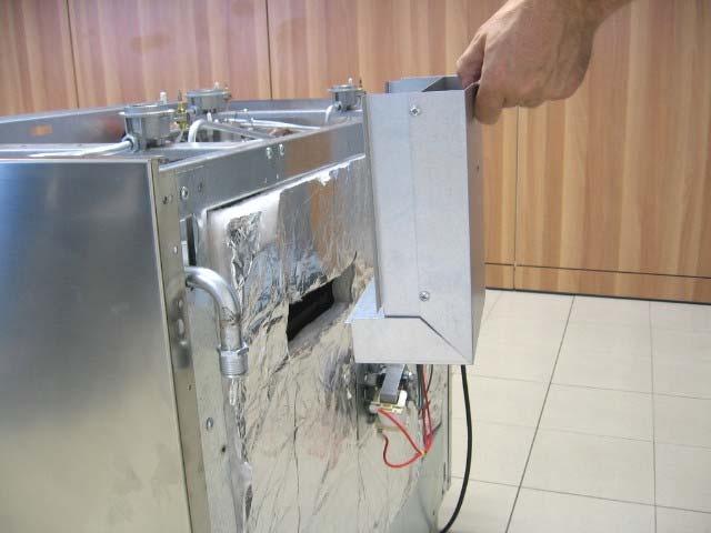
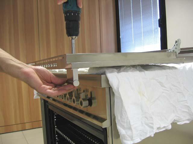
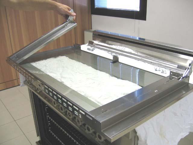
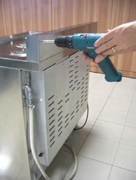
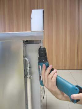
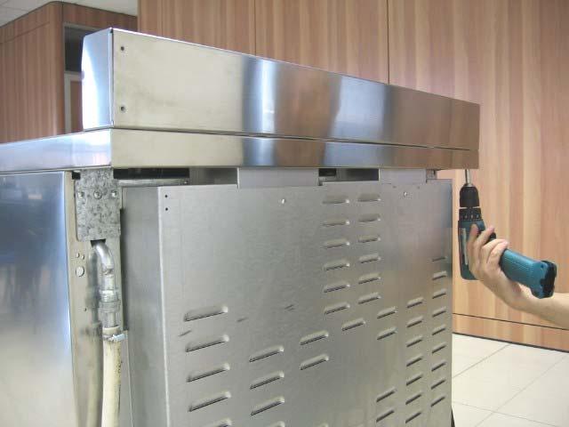
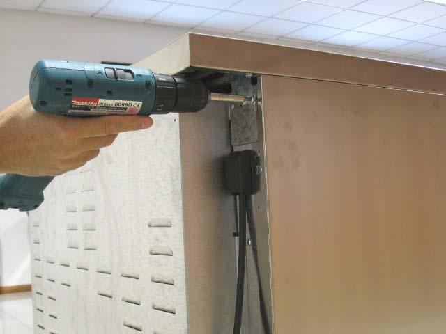
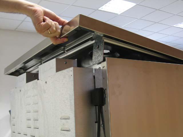
 Fix the front part of the backguard with the screws supplied with the backguard kit (fig.")
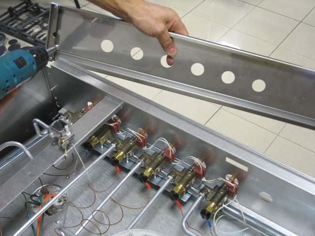
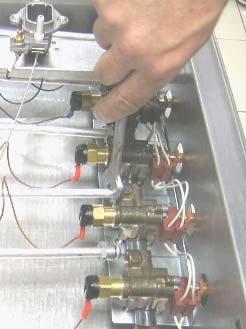
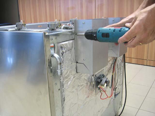
 1 2 3 4 WORKTOP FRONTGUARD INSTALLATION INSTRUCTIONS In order to increase the clearance between front edge of the worktop and the burners")
7 INSTALLATION MANUAL BACKGUARD INSTALLATION INSTRUCTION Please follow the following installation instructions afther installing the cooktop: 1) Remove n 2 screws fixing worktop as shown in fig.1 2) Place front part of the backguard and attach it from bottom side with the two removed screws (point 2) as shown in fig.2 3) Fix the front part of the backguard with the screws supplied with the backguard kit (fig.3) 4) Assemble back part with front part of backguard and fix them with a screw supplied with the backguard kit (fig.4) WORKTOP FRONTGUARD INSTALLATION INSTRUCTIONS In order to increase the clearance between front edge of the worktop and the burners for your safety it is recomended to install the worktop frontguard supplied with the appliance. For installation instructions follow the instructions indicated in the following figures 3
 above the adjacent base cabinet countertop. 2.The rangetop CANNOT be installed directly adjacent to sidewalls, tall cabinets, tall appliances, or other side vertical surfaces above 36\" (91.")
8 PROXIMITY TO SIDE CABINET INSTALLATION 1. This rangetop may be installed directly adjacent to existing 36" (91.5 cm) high base cabinets. IMPORTANT: The top grate support MUST be 3/8" (.95 cm) above the adjacent base cabinet countertop. 2.The rangetop CANNOT be installed directly adjacent to sidewalls, tall cabinets, tall appliances, or other side vertical surfaces above 36" (91.5 cm) high. There must be a minimum of 6" (15.2 cm) side clearance from the rangetop to such combustible surfaces above the 36" (91.5 cm) counter height Within the 6" (15.2 cm) side clearance to combustible vertical surfaces above 36" (91.4 cm) I the maximum wall cabinet depth must be 13" (33.0 cm) and wall cabinets within this 6" (15.2 cm) side clearance must be 18" (45.7 cm) above the 36" (91.4 cm) high countertop Wall cabinets above.the rangetop must be a minimum of 36" (91.4 cm) for the open top burner models and a minimum of 42" (106.7 cm) for the sealed burner models above the rangetop cooking surface for the full width of the rangetop. This minimum height requirement does nq1 apply if a rangehood is installed over the cooking surface. A B C D E F G H i L 6 (15.2cm) MIN 36 (91.5cm) 36 (91.5cm) 13 (33.0cm)MAX 18 (45.7cm)MIN 36 (91.5cm) 6 1/2(16.5cm) 1 (2.5cm) MIN 9/16 (1.8cm) 2 ( 5 cm) MIN 120 VAC/60 Hz withing 48 (122.9cm) of right rear or rangetop 4
9 COOKER HOOD INSTALLATION The bottom of the hood should be 25 ½ " (65 cm) min. to 31 ½ " (80 cm) above the countertop. Refer to the rangehood installation instructions for additional information. These dimensions provide for safe and efficient operation of the hood. ELECTRICAL CONNECTION This unit is manufactured for a polarized, grounded 120 volt/60 Hz, 16 amp system. Electric power consumption is about 1 W. The minimum of 102 VAC is required for proper operation of gas ignition systems. This circuit must be grounded and properly polarized. The unit is equipped witth a SJT power cord, and in case of replacement, the cable shall be replaced with one of the same type, size and length. WARNING Electrical Grounding Instructions This appliance is equipped with a three prong plug for your protection against shock hazard and should be plugged directly into a properly grounded socket. Do not cut or remove the grounding prong from this plug. WARNING ELECTRICAL SHOCK HAZARD Disconnect electrical power at the circuit breaker box or fuse before installing the appliance Electrically ground appliance Use copper conductors only. Failure to follow these instructions could result in seriuos injury or death 5
10 Wiring diagram For freestanding gas range model C36600X (Z X) C3Y0..U4X(2 or 5)A CAUTION: label all wires prior to disconnection when servicing controls. Wiring errors can cause improper and dangerous operation. Verify proper operation after servicing. For freestanding gas range model C36500X (Z X) C3W0..U4X(2 or 5)A CAUTION: label all wires prior to disconnection when servicing controls. Wiring errors can cause improper and dangerous operation. Verify proper operation after servicing. 6
11 GAS CONNECTION All gas connections must be made according to national and local codes. This gas supply (service) line must be the same size or greater than the inlet line of the appliance. This range uses a 1/2" NPT (see fig. in this chapter for details of gas connections installations) inlet. Sealant on ali pipe joints must be resistive to LP gas. 1. Manual Shut-off Valve: This installer-supplied valve must be installed in the gas service line ahead of the appliance in the gas stream and in a position where it can be reached quickly in the event of an emergency. The manual shut-off valve shall be installed properly in order to be accessible when appliance is installed in definitive position. In Massachusetts: A 'T' handle type manual gas valve must be installed in the gas supply line to this appliance. 2. Pressure Regulator (see fig. in this chapter) a) All cooking equipment must have a pressure regulator on the incoming service line for safe and efficient operation, since service pressure may fluctuate with local demand. The pressure regulator is supplied separately with the appliance; regulator has two female threads ½ NPT; it shall be installed properly in order to be accessible when appliance is installed in definitive position. b) Any conversion required must be performed by your dealer or a qualified licensed plumber or gas service company. Please provide the service person with this manual before work is started on the range. (Gas conversions are the responsibility of the dealer or end user.) c) This range can be used with Natural or LP/Propane gas. It is shipped from the factory adjusted for use with natural gas. d) Manifold pressure should be checked with a manometer, natural gas requires 4.0" W.c.P. and LP/Propane requires 11.0" W.C.P. Incoming line pressure upstream from the regulator must be 1" W.c.P. higher than the manifold pressure in order to check the regulator. The regulator used on this range can withstand a maximum input pressure of 1/2 PSI (14.0" W.c.P.) If the line pressure is in excess of that amount, a stepdown regulator will be required. e) The appliance, its individuai shut-off valve, and pressure regulator must be disconnected from the gas supply piping system during any pressure testing of that system at pressures in excess of 1/2 psig (3.45kPa). f) The appliance must be isolated from the gas supply piping system by closing its individuai manual shut-off valve during any pressure testing of the gas supply piping system at test pressures equal to or less than 1/2 psig (3.45 kpa). 3. Flexible Connections: a) If the unit is to be installed with flexible couplings and/or quick disconnect fittings, the installer must use a heavy-duty, AGA design-certified commerciai flexible connector of at least 1/2" (1.3 cm) ID NPT (with suitable strain reliefs) in compliance with ANSI Z21.41 and Z21.69 standards. b) In Massachusetts: The unit must be installed with a 36" (3-foot) long flexible gas connector. c) In Canada: CAN metal connectors for gas appliances and CAN M79 quick disconnect device for use with gas fuel. CAUTlON: Leak testing of the appliance shall be conducted according to the manufacturer's instructions. Before placing the oven into operation, always check for leaks with a soapy water solution or other acceptable method. DO NOT USE AN OPEN FLAME TO CHECK FOR LEAKS! PERFORMANCE CHECKLlST All burners are tested before leaving the factory. There are no adjustments for the burners if connected according to the information on the rating plate. Check each burner for proper operations. Flames should be blue in all settings. If service is required, contact your dealer for the name of their authorized servi ce agency. Gas conversions and initial installation are not the responsibility of the manufacturer. The installer should carry out the following performance checks. Refer to instructions below. 1. Check surface burner ignition. 2. Check low flame adjustment surface burner valve center stem adjustment. 3. Check for gas leaks (odors) at ali gas connections. FINAL PREPARATION 1. Some stainless steel parts may have a plastic protective wrap which must be removed. The interior of the oven should be washed thoroughly with hot. soapy water to remove film residues and any installation dust or debris before being used for food preparation, then rinsed and wiped dry. Solutions stronger than soap and water are rarely needed. 2. Ali stainless steel body parts should be wiped with hot, soapy water and with a liquid deaner designed for this materia!. If buildup occurs, do not use steel wool. abrasive cloths, cleaners, or powders! If it is necessary to scrape stainless steel to remove encrusted materials, soak with hot, wet cloths to loosen the material, then use a wood or nylon scraper. Do not use a metal knife, spatula, or any other metal tool to scrape stainless steel! Scratches are almost impossible to remove. NOTE: These installation instructions should remain with the unit for future reference. The electrical diagram is located in the backside or the ccoker 7
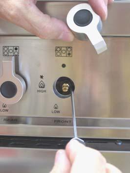
12 REPLACEMENT PARTS Only authorized replacement parts may be used in performing service on the appliance. Replacement parts are available from factory authorized parts distributors. CONVERSIONE TO DIFFERENT TYPES OF GAS Before carrying out any maintenance work, disconnect the appliance from the gas and electric supply. For Natural Gas fit regulator assembly described in Fig. Adaptation of the pressure regulator for use with different type of gas The pressure regulator supplied with the appliance is a convertible type pressure regulator for use with Natural Gas at a nominal outlet pressure of 4 w.c. or LP gas at a nominal outlet pressure of 11 w.c. and it is pre-arranged from the factory to operate with one of these gas/pressure as indicated in the pre-arranging labels affixed on the appliance, package and Instruction booklet. To convert the regulator for use with the other gas different from which one it is pre-arranged it is enough perform the following operations: 1) Unscrew by hand the upper metal stopper of the regulator. 2) Unscrew by hand the white plastic piece screwed under the above mentioned metal stopper, afterward screw it again in opposite way under the metal stopper (for gas reference see the written LP and NAT with relative indicating arrows on the white piece). 3) Screw again by hand the metal stopper in the original position on the regulator. Operating in this way the gas regulator is converted for use with the other gas/pressure. - CHANGING THE NOZZLES FOR USE WITH OTHER TYPES OF GAS: To change the nozzles of the burners use the following procedure: Lift up the burners and unscrew the nozzles ( Fig.) using an adjustable spanner of 7 mm and change the nozzles with those designed for the new gas supply according to the information given in TABLE shown below. 8
13 Models C36600X (Z X) [C3Y0..U4X(2 or 5)A] Adapting to different types of gas Burner Position Injector Gas Pressure Max Rate Min Rate By-pass diam. [mm.] Type [i.w.c.] [BTU/h] [W] [BTU/h] [W] diam. [mm] Auxiliary Front R 0,90 NG Regulated 0,54 LP (Propane) ,29 Semi-Rapid Rear L & C 1,18 NG Regulated Front C 0,70 LP (Propane) ,36 Rapid Rear L 1,55 NG Regulated 0,92 LP (Propane) ,47 Front L Inner 0,80 NG Regulated Dual Burner 0,49 LP (Propane) ,29 Front L Outer N 2 x 1,15 NG Regulated N 2 x 0,70 LP (Propane) ,65 Models C36500X (Z X) [C3W0..U4X(2 or 5)A] Adapting to different types of gas Burner Position Injector Gas Pressure Max Rate Min Rate By-pass diam. [mm.] Type [i.w.c.] [BTU/h] [W] [BTU/h] [W] Diam. [mm] Auxiliary Front R 0,90 NG Regulated 0,54 LP (Propane) ,29 Semi-Rapid Rear L and R 1,18 NG Regulated 0,70 LP (Propane) ,36 Rapid Rear L 1,55 NG Regulated 0,92 LP (Propane) ,47 Centre Inner 0,80 NG Regulated Dual Burner 0,49 LP (Propane) ,29 Centre Outer N 2 x 1,15 NG Regulated N 2 x 0,70 LP (Propane) ,65 CAUTION: save the orifices removed from the appliance for future use Regulation of burners Work surface burner adjustment: follow the instructions below to adjust the work surface burner minimum: 1) Light the burner and set the knob to the MINIMUM position (small flame). 2) Remove the knob of the valve that is press fit on the rod of that valve. 3) The cooker is equipped with safety valves, use a small slotted screwdriver the choke valve located on the valve body and turn the choke screw to the right or left until the burner flame is adjusted to minimum 4) Make sure that the flame does not go out when switching quickly from the MAXIMUM to the MINIMUM position. WARNING: The above-mentioned adjustment should be made only for natural gas, while for operation with liquid gas the screw must be locked at the end in a clockwise direction. The grill burner always operates at maximum and therefore no minimum adjustment is required. 9


 [M3W0..U4X(2 or 5)A]Fig. A 2. Medium burner Model C36600X (Z36 6 00 X) [M3Y0..U4X(2 or 5)A]Fig. B 3. Rapid burner 4. Dual burner Fig. A Fig.")
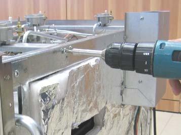
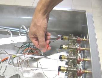
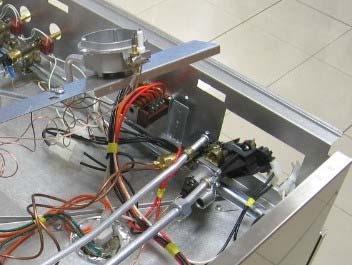
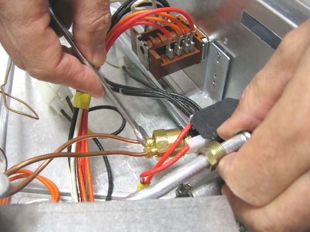
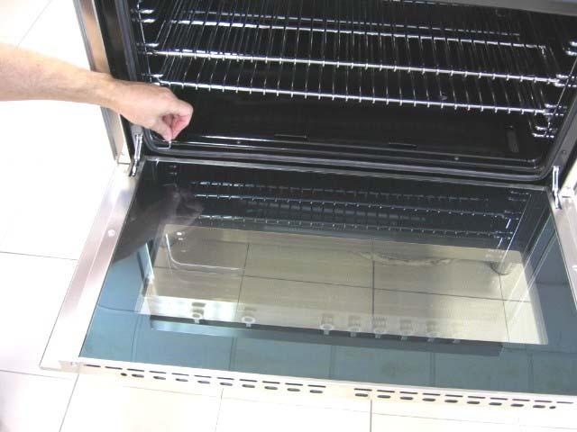
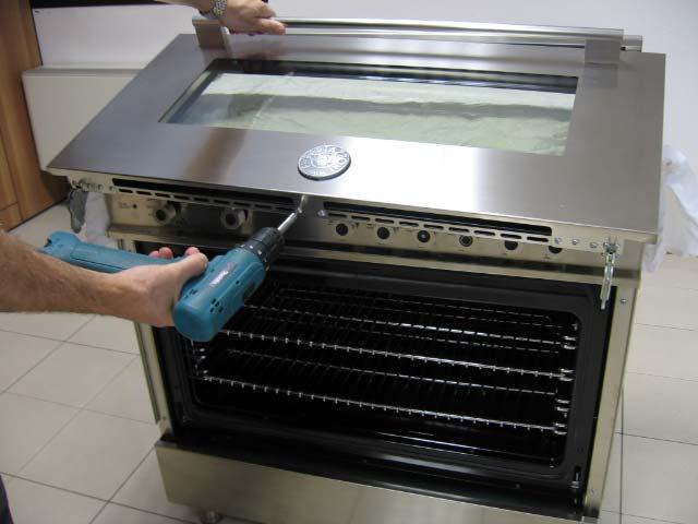
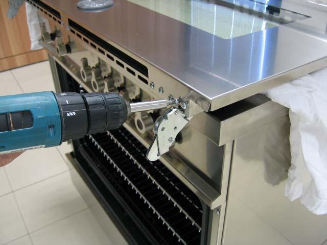
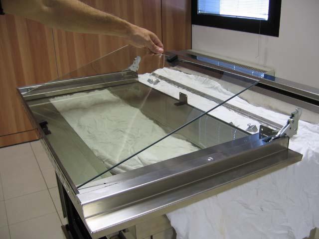
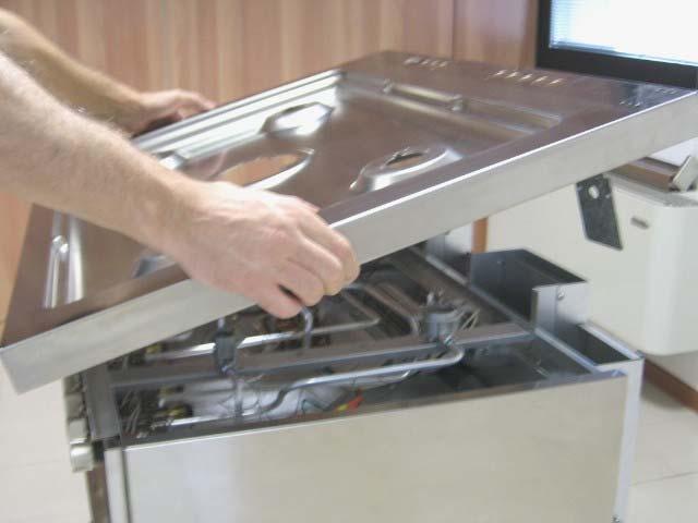
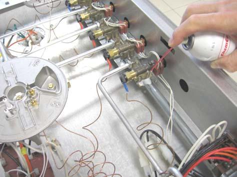
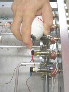
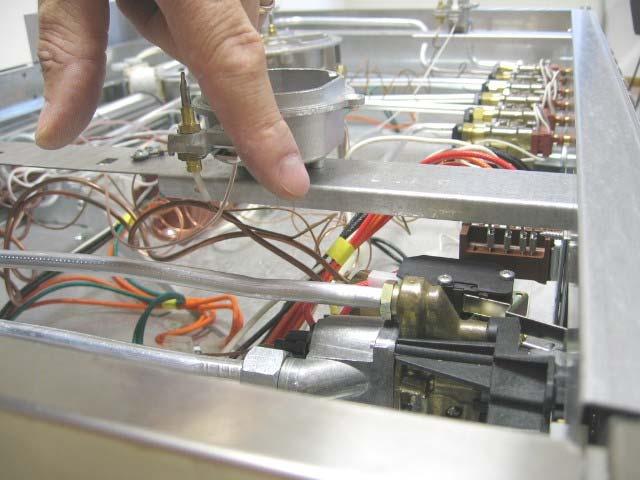
14 SERVICE & MAINTENANCE INSTRUCTIONS Service and maintenance only to be carried out by an authorised person To replace parts such as burners, valves and electric components, the appliance must be open removing the worktop. Note: if the valves must be replaced, first disassemble the ignitions switches wires. It is recommended to replace the valve gaskets each time the valve is replaced, thus ensuring a perfect seal between the body and the gas train. WARNING: After first installation of the appliance or after any service intervention concerning main gas parts of the appliance, make the leak test using water with soap on the gas connections in order to verify the correct installation. Do not use fire for gas leak testing. DESCRIPTIONS USER MANUAL DESCRIPTIVE CAPTION FOR HOB DESCRIPTION OF HOBS 1. Small Burner Model C36500X (Z X) [M3W0..U4X(2 or 5)A]Fig. A 2. Medium burner Model C36600X (Z X) [M3Y0..U4X(2 or 5)A]Fig. B 3. Rapid burner 4. Dual burner Fig. A Fig. B CONTROL PANEL DESCRIPTION On the control panel, small symbols show the function of each knob or key. Here as follows are the several controls that a cooker can have: the symbol shows the disposition of burners on the worktop, the full dot identifies the burner in object (in this case the front burner on the right). WARNINGS: Keeping appliance area clear and free from combustible materials, gasoline and other flammable vapors and liquid. Do not store dangerous or flammable material in the cabinet areas above appliance; store them in a safe place in order to avoid potential hazards. For safe use of appliance, do not use it for space heating. Do not use aerosol sprays in the vicinity of this appliance while it is in operation 10

 and then press the knob down to")
15 USING BURNERS A diagram is etched on the control panel above each knob which indicates which burner corresponds to that knob. Manual ignition: Manual ignition is always possible even when the power is cut off or in the event of prolonged power failure. Turn the knob that corresponds to the burner selected counterclockwise to the MAXIMUM position at the etched star (large flame) and place a lit match up to the burner. Automatic electric ignition: Turn the knob that corresponds to the burner selected anticlockwise direction to the MAXIMUM position at the etched star (large flame) and then press the knob down to activate the spark ignition. Once ignited, keep pressing the knob for about 10 seconds to allow the flame to heat the thermocouple. If the burner does not remain alight after releasing the knob repeat the above procedure, Note: It is recommended not to try to ignite the burner if the relative flame cap is not in the correct position Note: Dual burner is composed by two burner (inside and outside); each one operates under the relative gas valve indipendently from the other one. Tips for using burners correctly: WARNING: During use of each gas burner(s) adjust the burner flame size properly so it does not extend beyond the edge of the cooking utensil. This is an instruction based on safety considerations - Use suitable pots for each burner (see Fig. and Table ) - When the liquid is boiling, turn down the knob to the MINIMUM position. - Always use pots with a cover. Correct flame aspect: verify that aspect flame of the worktop burners be completely blue and with an aspect as indicated in figure(flame) Table Burner Recommended pan diameters inches (mm) Small 35½ -551/8 (90 140) Medium 551/8-1023/8 ( ) Large 707/8-1023/8 ( ) Dual burner 862/3-1023/8 ( ) WARNING: check the position of the burner caps before operation. Correct usage of pans: - Dry the bottom of the pan before placing it on the hotplate. - Use pots with a flat, thick bottom, except for wok cooking. - When using the burners, ensure that the handles of the pans are correctly positioned. Keep children away from the appliance. - When cooking foods with oil and fat, which are very flammable, the user should not leave the appliance unattended. WOK PAN: To use the wok pan, please utilize a suitable wok adaptor grid; wok pan external diameter shall not be less than 10 (25cm) and not more than 16 (40cm). WARNING: If the power is cut off, the burners can be lit with matches. The burners equipped with a safety thermocouple can only be lit when the knob is in the MAXIMUM position (large flame etching). 11
16 CLEANING THE APPLIANCE: Never use abrasive cleaners Before cleaning the appliance it should be disconnected from the power supply. Cleaning the work surface: periodically clean the burner heads, the cast iron pan supports and the burner caps using warm water. Any spillage must always be removed as soon as possible using a rag. If it become difficult to open or close a valve, do not force it, but immediately request the assistance of the technical service personnel. Cleaning the enamelled parts: Enamelled parts should be cleaned frequently with soapy water. Never use abrasive powder. Do not leave acidi or alkaline substances on the enamelled parts (such as vinegar, lemon juice, salt, tomato sauce, etc.) and do not wash the enamelled parts while they are still hot. Cleaning the stainless steel parts: Clean the parts with soapy water and dry them with a soft cloth. The shine is maintained by periodically using specific stainless steel cream cleaner. Never use abrasive powders. Use specific stainless steel cream cleaner to eliminate the glue remains afther the elimination of the blue plastic protection film on the worktop after installation. Cleaning the burner caps: Lift the burner caps from the burner heads and wash them in soapy water and dry thoroughly. Before replacement on the burner head ensure that the holes are not clogged. ATTENTION: for further details about cleaning of the appliance, please contact your applliance retailer. AFTER SALE SERVICE: Please note here below details for after save service. Refer to warranty certificate for warranty condiftions Dealer /Importer: Name, address, phone Name SERVICE CENTERS Phone MANUFACTURER: BERTAZZONI SPA VIA PALAZZINA, GUASTALLA (REGGIO E.) ITALY Tel. 0522/ telefax 0522/
17 SPARE PART LIST Quantity Number Drawing Code Description C3W0..U4X5AUA C3Y0..U4X5AUA CIRCUIT DIAGRAM PART FOR BURNER FIXING PART FOR DUAL WOK AND SEMI RAPID BURNERS SMALL BURNER SEMI RAPID BURNER RAPID BURNER DUAL BURNER SMALL FLAME SPREADER MEDIUM FLAME SPREADER RAPID FLAME SPREADER ULTRA RAPID FLAME SPREADER COVER FOR SMALL FLAME SPREADER COVER FOR MEDIUM BURNER COVER FOR RAPID BURNER COVER OUT FOR DUAL BURNER FLAME SPREADER COVER IN FOR DUAL BURNER FLAME SPREADER WORKTOP FRONTGUARD BRIDLE FOR FIXING GAS VALVES GAS VALVE BY PASS GAS VALVE BY PASS GAS VALVE BY PASS GAS VALVE BY PASS STOP SPRING FOR SPARK PLUG SPARK PLUG 350MM SPARK PLUG 700MM SPARK PLUG FOR DUAL BURNER ACCUMULATOR REDUCTIONGRID TERMOCOUPLE MM TERMOCOUPLE MM TERMOCOUPLE MM TERMOCOUPLE FOR DUAL BURNER TERMINAL SEPARATOR ADAPTER FOR WOK BURNER PAN SUPPORT DASYCHAIN SWITCH DASYCHAIN SWITCH CAST IRON PAN SUPPORT 2 BURNERS CAST IRON PAN SUPPORT 1 BURNER GAS VALVE KNOB FRONT RISER REAR RISER CONTROL PANEL CONTROL PANEL BRIDLE FOR FIXING GAS VALVES/THERMOSTAT CONTROL SUPPORT WORK TABLE WORK TABLE GAS COLLECTOR GAS COLLECTOR TUBE FOR RIGHT FRONT BURNER
18 TUBE FOR RIGHT BACK BURNER REAR CENTRAL TUBE TUBE FOR LEFT BACK BURNER FRONT CENTRAL TUBE TUBE FOR EXTERNAL DUAL BURNER TUBE FOR INTERNLA DUAL BURNER CENTRAL TUBE EXTERNAL CENTRAL TUBE TUBE FOR FRONT LEFT BURNER 1 14
19 15

20 SERVICING - WARNING - WORK SAFELY BERTAZZONI PRO PRODUCTS SERVICE GUIDE Bertazzoni PRO products Service guide 1 rev
21 SERVICING - WARNING - WORK SAFELY Bertazzoni PRO products Service guide 2 rev
22 SERVICING - WARNING - WORK SAFELY o Do not remove permanently affixed labels, warnings, or plates from the product. This may void the warranty. o Please observe all local and national codes and ordinances. o Please ensure that this product is properly grounded. o The electrical plug should always be accessible. o Installation must conform with local codes or in the absence of codes, the National Fuel Gas Code ANSIZ223.1-latest edition. o Electrical installation must be in accordance with the National Electrical Code, ANIS/NFPA70 - latest edition and/or local codes. o IN CANADA: Installation must be in accordance with the current CAN/CGA- B149.1 National Gas Installation Code or CAN/CGA-B 149.2, Propane Installation Code and/or local codes. Electrical installation must be in accordance with the current CSA C22.1 Canadian Electrical Codes Part 1 and/or local codes. o Installation of any gas-fired equipment should be made by a licensed plumber. o A manual gas shut-off valve must be installed in the gas supply line ahead of the oven in the gas flow for safety and ease of service. WARNING: If the information in this manual is not followed exactly, a fire or explosion may result causing property damage, personal injury or death. Bertazzoni PRO products Service guide 3 rev
23 SERVICING - WARNING - WORK SAFELY Sections Tools 5 Troubleshooting 6 How to reach 12 Electric diagrams 39 Bertazzoni PRO products Service guide 4 rev
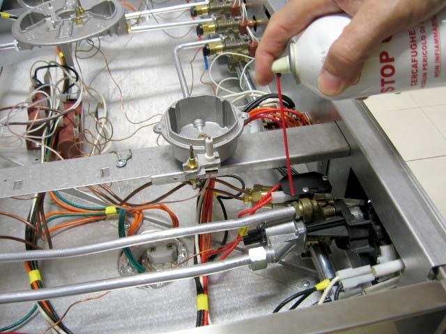
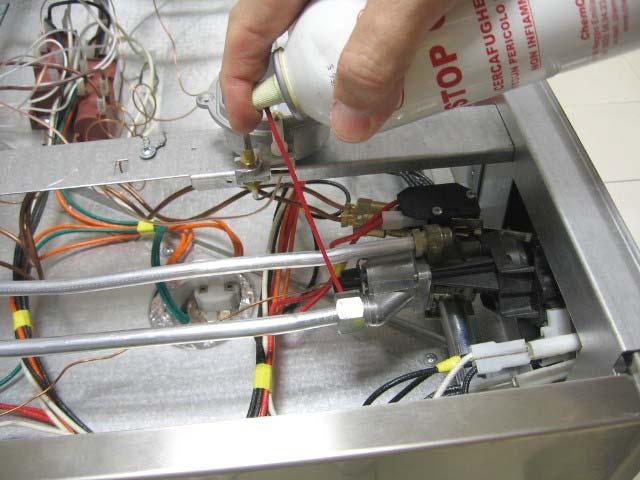
24 SERVICING - WARNING - WORK SAFELY Tools Gas detector spray Phillips screwdriver ph 2 X 100 Torx screwdriver X15 Flat Screwdriver 2,5 X 0,4 X 150 Flat Screwdriver small Single head wrench (8, 10, 13, 15, 17, 19, 21, 22, 24) Tubular spanner diam. 7, diam. 8 and diam. 10 Bertazzoni PRO products Service guide 5 rev
25 SERVICING - WARNING - WORK SAFELY Troubleshooting Low flame No gas Gas Smell Electric ignition is not working The burner does not remain on The range surface is too hot The fan is not turning Too high flame The food is burning in the oven The food is not cooking in the oven Blocked gas tap Continual spark Electric problem Bertazzoni PRO products Service guide 6 rev
26 SERVICING - WARNING - WORK SAFELY TIP: on all burners at max CHECK: gas supply pressure TIP: on one burner at max CHECK: injector TIP: on one burner at min CHECK: gas valve TIP: with cold oven CHECK: thermostat Low flame No gas TIP: on all burners CHECK: gas supply line gas pressure TIP: on one burner CHECK: injector Bertazzoni PRO products Service guide 7 rev
27 SERVICING - WARNING - WORK SAFELY TIP: with all closed gas valves CHECK: gas supply connection TIP: with one closed gas valves CHECK: gas valves TIP: with closed thermostat CHECK: thermostat Gas Smell TIP: with open gas valves and thermostat CHECK: the tubes Electric ignition is not working TIP: the electric plug is inserted but electric ignition is not working CHECK: cable box connection TIP: on all burners CHECK: spark generator or daisychain switch TIP: on one burner CHECK: spark plug The burner does not remain on TIP: one burner does not remain on CHECK: thermocouple or gas valve TIP: the burner (oven or broiler) does not remain on CHECK: thermostat or thermocouple Bertazzoni PRO products Service guide 8 rev
28 SERVICING - WARNING - WORK SAFELY TIP: the cooling fan is not working CHECK: cooling fan The range surface is too hot TIP: the oven burner flame is not going to min CHECK: thermostat (bulb) TIP: the oven burner flame is too high CHECK: oven injector TIP: the broiler burner flame is too high CHECK: broiler injector The fan is not turning TIP: the fan is turning with difficulty CHECK: oven convection fan TIP: the fan is not turning at all CHECK: oven switch (or oven convection fan) TIP: on all burners CHECK: gas supply pressure TIP: on one burner CHECK: injector or gas valve Too high flame Bertazzoni PRO products Service guide 9 rev
29 SERVICING - WARNING - WORK SAFELY The food is burning in the oven TIP: the oven burner flame is not going to min. CHECK: thermostat (bulb) TIP: the oven burner flame is too high CHECK: oven injector TIP: the broiler burner flame is too high CHECK: broiler injector The food is not cooking in the oven TIP: the oven burner flame is going to min very quickly CHECK: thermostat (bulb) TIP: the oven burner flame is very low CHECK: oven injector TIP: the broiler burner flame is very low CHECK: broiler injector TIP: one blocked gas valve CHECK: gas valve Blocked gas valve Bertazzoni PRO products Service guide 10 rev
30 SERVICING - WARNING - WORK SAFELY TIP: on all burners CHECK: daisychain switch Continous sparking Electric Problem TIP: just inserted the electric plug CHECK: cable box power supply cable TIP: when I turn on the light CHECK: oven bulb with holder or oven switch TIP: when I turn on the fan CHECK: oven convection fan or oven switch Bertazzoni PRO products Service guide 11 rev
31 SERVICING - WARNING - WORK SAFELY How to reach Common parts Convection fan Gas manifold Oven burner Oven door Work top Specific parts Spark Generator Cooling fan Oven light / fan switch Daisychain switch Gas valve Injector (Burner) (Broiler) (Oven) Oven bulb with holder Spark plug Cable box Thermocouple Thermostat Tubes Bertazzoni PRO products Service guide 12 rev


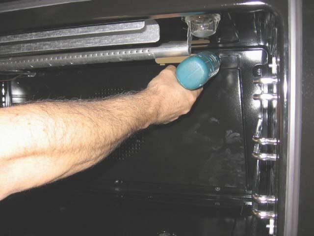
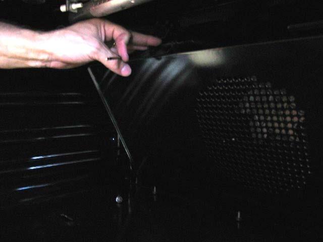
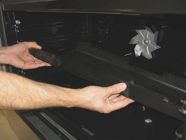
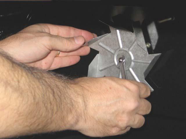
32 SERVICING - WARNING - WORK SAFELY Convection fan Bertazzoni PRO products Service guide 13 rev


33 SERVICING - WARNING - WORK SAFELY Bertazzoni PRO products Service guide 14 rev


34 SERVICING - WARNING - WORK SAFELY Gas manifold Bertazzoni PRO products Service guide 15 rev


35 SERVICING - WARNING - WORK SAFELY Bertazzoni PRO products Service guide 16 rev


36 SERVICING - WARNING - WORK SAFELY Bertazzoni PRO products Service guide 17 rev


37 SERVICING - WARNING - WORK SAFELY Bertazzoni PRO products Service guide 18 rev

38 SERVICING - WARNING - WORK SAFELY Oven burner Bertazzoni PRO products Service guide 19 rev


39 SERVICING - WARNING - WORK SAFELY Oven door Bertazzoni PRO products Service guide 20 rev


40 SERVICING - WARNING - WORK SAFELY Bertazzoni PRO products Service guide 21 rev


41 SERVICING - WARNING - WORK SAFELY Bertazzoni PRO products Service guide 22 rev


42 SERVICING - WARNING - WORK SAFELY Work top Bertazzoni PRO products Service guide 23 rev


43 SERVICING - WARNING - WORK SAFELY Bertazzoni PRO products Service guide 24 rev


44 SERVICING WARNING - WORK SAFELY Spark Generator 1 2 Cooling fan Bertazzoni PRO Products Service guide 25 rev


45 SERVICING WARNING - WORK SAFELY Oven Light / Fan Switch 1 2 Daisychain Ignition switch Bertazzoni PRO Products Service guide 26 rev


46 SERVICING WARNING - WORK SAFELY 5 6 Gas valve Bertazzoni PRO Products Service guide 27 rev


47 SERVICING WARNING - WORK SAFELY 5 Injector (Burner) 1 2 Bertazzoni PRO Products Service guide 28 rev


48 SERVICING WARNING - WORK SAFELY Injector (Broiler) Bertazzoni PRO Products Service guide 29 rev
49 SERVICING WARNING - WORK SAFELY Injector (Oven) Bertazzoni PRO Products Service guide 30 rev


50 SERVICING WARNING - WORK SAFELY 7 8 Oven bulb with holder 1 2 Bertazzoni PRO Products Service guide 31 rev


51 SERVICING WARNING - WORK SAFELY Spark plug Bertazzoni PRO Products Service guide 32 rev


52 SERVICING WARNING - WORK SAFELY 7 8 Cable Box Bertazzoni PRO Products Service guide 33 rev


53 SERVICING WARNING - WORK SAFELY Thermocouple Bertazzoni PRO Products Service guide 34 rev

54 SERVICING WARNING - WORK SAFELY Bertazzoni PRO Products Service guide 35 rev


55 SERVICING WARNING - WORK SAFELY Thermostat Bertazzoni PRO Products Service guide 36 rev


56 SERVICING WARNING - WORK SAFELY Tubes Bertazzoni PRO Products Service guide 37 rev


57 SERVICING WARNING - WORK SAFELY Bertazzoni PRO Products Service guide 38 rev
58 SERVICING WARNING - WORK SAFELY Electric diagrams Bertazzoni PRO Products Service guide 39 rev
Installation, Service and User Instructions Built-in gas cooktops BERTAZZONI
 Installation, Service and User Instructions Built-in gas cooktops BERTAZZONI DIMENSIONS: 36 (915 mm)(w) x 253/16 (640 mm)(d) Models CB36500X [C3W0..U7X (2 or 5)A] Models CB36600X [C3Y0..U7X(2 or 5)A] IMPORTANT
SPARE PARTS LIST C36500X
 SPARE PARTS LIST C36500X NUMBER COMPONENT DESCRIPTION QUANTITY 1 601639 CIRCUIT DIAGRAM 1 11 202387 BURNERS FLASK 2 22 202397 LOAD BEARING BOTTOM 1 55 404198 WORKTOP FRONTGUARD 1 80 504160 COVER FOR SMALL
User Instructions FREESTANDING GAS RANGES BERTAZZONI
 User Instructions FREESTANDING GAS RANGES BERTAZZONI DIMENSIONS: 36 (915 mm)(w) x 253/16 (640 mm)(d) x36 (915 mm)(h) Models X365GGVX (X36 5 00 X) [M3W0GTU4X(2 or 5)A] Models X366GGVX (X36 6 00 X) [M3Y0GTU4X(2
Gas Cooktop Installation, User and Service Instructions GMS 955.1
 Gas Cooktop Installation, User and Service Instructions GMS 955.1 IMPORTANT: SAVE FOR LOCAL ELECTRICAL INSPECTOR S USE. READ AND SAVE THESE INSTRUCTIONS FOR FUTURE REFERENCE. OBSERVE ALL FEDERAL, STATE
Viking Installation Guide
 Viking Installation Guide Viking Range Corporation 111 Front Street Greenwood, Mississippi 38930 USA (662) 455-1200 For product information, call 1-888-VIKING1 (845-4641) or visit the Viking web site at
Installation, Service and User Instructions FREESTANDING GAS RANGES BERTAZZONI. DIMENSIONS: 30 (762 mm)(w) x 253/16 (640 mm)(d) x36 (915 mm)(h)
(w) x 253/16 (640 mm)(d) x36 (915 mm)(h)") Installation, Service and User Instructions FREESTANDING GAS RANGES BERTAZZONI DIMENSIONS: 30 (762 mm)(w) x 253/16 (640 mm)(d) x36 (915 mm)(h) Models X304GGVX [M7S0GTU4X(2 or 5)A] IMPORTANT - PLEASE READ
Installation, Service and User Instructions FREESTANDING GAS RANGES BERTAZZONI DIMENSIONS: 30 (762 mm)(w) x 253/16 (640 mm)(d) x36 (915 mm)(h) Models X304GGVX [M7S0GTU4X(2 or 5)A] IMPORTANT - PLEASE READ
Installation Guide. 5 Series VGC and VGSU Built-In Gas Cooktops
 Installation Guide 5 Series VGC and VGSU Built-In Gas Cooktops Table of Contents Warnings & Important Safety Instructions 3 Dimensions VGC Cooktops 6 Specifications VGC Cooktops 7 Dimensions VGSU Cooktops
BERTAZZONI. Installation, Service and User Instructions. MODEL [MLS0GTU4X(2 or 5)A] FREESTANDING GAS RANGES
![BERTAZZONI. Installation, Service and User Instructions. MODEL [MLS0GTU4X(2 or 5)A] FREESTANDING GAS RANGES](/thumbs/91/107403083.jpg "BERTAZZONI. Installation, Service and User Instructions. MODEL [MLS0GTU4X(2 or 5)A] FREESTANDING GAS RANGES") Installation, Service and User Instructions FREESTANDING GAS RANGES BERTAZZONI DIMENSIONS: 24 (605 mm)(w) x 25 1/8 (640 mm)(d) x36 (911 mm)(h) MODEL X244GGVX [MLS0GTU4X(2 or 5)A] 310287 IMPORTANT - PLEASE
Installation, Service and User Instructions FREESTANDING GAS RANGES BERTAZZONI DIMENSIONS: 24 (605 mm)(w) x 25 1/8 (640 mm)(d) x36 (911 mm)(h) MODEL X244GGVX [MLS0GTU4X(2 or 5)A] 310287 IMPORTANT - PLEASE
Viking Installation Guide
 Viking Installation Guide Viking Range Corporation Front Street Greenwood, Mississippi 38930 USA (66) 455-00 For product information, call -888-VIKING (845-464) or visit the Viking Web site at vikingrange.com
INSTALLATION INSTRUCTIONS
 INSTALLATION INSTRUCTIONS VGSU SERIES BUILT-IN GAS COOKTOPS VIKING RANGE CORPORATION 111 Front Street Greenwood, Mississippi 38930 USA (662) 455-1200 IMPORTANT: PLEASE READ AND FOLLOW 1. Before beginning,
INSTALLATION, USE & CARE MANUAL FREESTANDING GAS RANGES
 INSTALLATION, USE & CARE MANUAL FREESTANDING GAS RANGES Models X365GGVX (X36 5 00 X) Models X365GGVBI Models X365GGVCR Models X365GGVGI Models X365GGVRO Models X365GGVVI Models X365GGVVE Models X365GGVBL
INSTALLATION, USE & CARE MANUAL FREESTANDING GAS RANGES. Models
 INSTALLATION, USE & CARE MANUAL FREESTANDING GAS RANGES Models MAS36 5 GAS XT MAS36 5 GAS XE [M3W0GNA7X(2,5)AUA] [M3W0GNA7X(2,5)AUG] 310821 1 From the desk of the President BERTAZZONI SpA Via Palazzina
INSTALLATION, USE & CARE MANUAL FREESTANDING GAS RANGES
 INSTALLATION, USE & CARE MANUAL FREESTANDING GAS RANGES DIMENSIONS: 30 (762 mm)(w) x 253/16 (640 mm)(d) x36 (915 mm)(h) MODELS A304GGVXE A304GGVXT [M7S0GNA4X(2,5)AUG] [M7S0GNU4X(2,5)AUA] 310447 1 From
DESIGN CLASS FUNCTION
 PROFESSIONAL QUALITY COOKING EQUIPMENT INSTALLATION MANUAL FOR PERFORMER SLIDE-IN COOK TOPS MODEL NUMBERS: AROBSCT-424, AROBSCT-242GD, AROBSCT-24X2GR, AROBSCT-430, AROBSCT-636, AROBSCT-436GD, AROBSCT-436GR,
Installation, Service and User Instructions FREESTANDING GAS RANGES BERTAZZONI
 Installation, Service and User Instructions FREESTANDING GAS RANGES BERTAZZONI DIMENSIONS: 36 (915 mm)(w) x 253/16 (640 mm)(d) x36 (915 mm)(h) Models X365GGVX (X36 5 00 X) [M3W0GTU4X(2 or 5)A] Models X366GGVX
Installation. Freestanding 30 Gas Self-Clean Sealed Burner Range
 Installation Viking Range Corporation Front Street Greenwood, Mississippi 890 USA (66) 455-00 For product information, call -888-VIKING (845-464) or visit the Viking Website at vikingrange.com Freestanding
Viking Installation Guide
 Viking Installation Guide Viking Range Corporation Front Street Greenwood, Mississippi 38930 USA (66) 455-00 For product information, visit the Viking Web site at vikingrange.com Professional Built-In
INSTALLATION, USE & CARE MANUAL FREESTANDING GAS RANGES
 INSTALLATION, USE & CARE MANUAL FREESTANDING GAS RANGES DIMENSIONS: 48 (1220 mm)(w) x 253/16 (640 mm)(d) x36 (915 mm)(h) Models PRO48 6G GAS X MTYKQPU7X5A Models PRO48 6G GAS AR MTYKQPU7S5A Models PRO48
Warning! This range can tip. Injury to persons could result. Install anti-tip device shipped with range. See Installation Instructions. WARNING!
 IMPORTANT SAFETY INFORMATION PLEASE READ AND FOLLOW THESE IMPORTANT INSTRUCTIONS FOR THE SAFETY OF YOUR HOME AND OF THE PEOPLE LIVING IN IT. Save this Manual for local electrical inspector s use. Read
IMPORTANT SAFETY INSTRUCTIONS Carefully read the following Important information redarding installation safety and maintenance.
 IMPORTANT SAFETY INSTRUCTIONS Carefully read the following Important information redarding installation safety and maintenance. Keep these instruction for future reference. USERS OPERATING INSTRUCTIONS
Viking Installation Guide
 Viking Installation Guide Viking Range Corporation Front Street Greenwood, Mississippi 38930 USA (662) 455-200 For product information, call -888-VIKING (845-464) or visit the Viking Web site at vikingrange.com
Viking Installation Guide
 Viking Installation Guide Viking Range Corporation Front Street Greenwood, Mississippi 38930 USA (66) 455-00 For product information, call -888-VIKING (845-464) or visit the Viking Web site at vikingrange.com
Installation, Service and User Instructions FREESTANDING GAS RANGES BERTAZZONI. DIMENSIONS: 48 (W) x 25 1/8 (D) x 35 1/ /2"(H) MODEL:
 x 25 1/8 (D) x 35 1/ /2(H) MODEL:") Installation, Service and User Instructions FREESTANDING GAS RANGES BERTAZZONI DIMENSIONS: 48 (W) x 25 1/8 (D) x 35 1/8 + 1 1/2"(H) MODEL: X486GGGVX [MTYKQZU4X(2 or 5)A] 310286 IMPORTANT - PLEASE READ
Installation, Service and User Instructions FREESTANDING GAS RANGES BERTAZZONI DIMENSIONS: 48 (W) x 25 1/8 (D) x 35 1/8 + 1 1/2"(H) MODEL: X486GGGVX [MTYKQZU4X(2 or 5)A] 310286 IMPORTANT - PLEASE READ
Installation. Professional Freestanding Sealed Burner Gas Ranges VGCC530 / VGCC536 / VGCC548 / VGCC560 CVGCC530 / CVGCC536 / CVGCC546 / CVGCC560
 Installation Professional Freestanding Sealed Burner Gas Ranges VGCC530 / VGCC536 / VGCC548 / VGCC560 CVGCC530 / CVGCC536 / CVGCC546 / CVGCC560 Table of Contents Warnings & Important Safety Instructions
GAS COOKTOP INSTALLATION INSTRUCTIONS
 INSTALLATION AND SERVICE MUST BE PERFORMED BY A QUALIFIED INSTALLER. IMPORTANT: SAVE FOR LOCAL ELECTRICAL INSPECTOR'S USE. READ AND SAVE THESE INSTRUCTIONS FOR FUTURE REFERENCE. WARNING If the information
DESIGN CLASS FUNCTION
 PROFESSIONAL QUALITY COOKING EQUIPMENT INSTALLATION MANUAL FOR MEDALLION DUAL FUEL RANGES MODEL NUMBERS: ARR-304DF, ARR-366DF, ARR-364GDDF, ARR-364GRDF, ARR-486GDDF, ARR-486GRDF, ARR-4822GDDF, ARR-484X2GRDF,
Viking Installation Guide
 Viking Installation Guide Viking Range Corporation Front Street Greenwood, Mississippi 890 USA (66) 455-00 For product information, call -888-VIKING (845-464) or visit the Viking Web site at vikingrange.com
INSTALLATION INSTRUCTIONS
 INSTALLATION INSTRUCTIONS VGSO166 BUILT-IN GAS OVEN VIKING RANGE CORPORATION 111 Front Street Greenwood, Mississippi (MS) 38930 USA (662)453-1200 Retain for Future Use IMPORTANT - PLEASE READ AND FOLLOW
Installation. Professional Freestanding Open Burner Ranges VGIC5301, CVGIC5301, VGIC5361, CVGIC5361
 Installation Professional Freestanding Open Burner Ranges VGIC5301, CVGIC5301, VGIC5361, CVGIC5361 Table of Contents Warnings & Important Safety Instructions 3 Dimensions 6 Specifications 8 Clearance Dimensions
Installation. Professional Freestanding Ranges
 Installation Professional Freestanding Ranges Table of Contents Warnings & Important Safety Instructions 3 Dimensions 6 Specifications 8 Clearance Dimensions (Proximity to Cabinet 0 Clearance Dimensions
Multi-Function Cooktop
 INSTALLATION GUIDE Multi-Function Cooktop Contents Wolf Multi-Function Cooktop.................... 3 Multi-Function Cooktop Specifications............ 4 Multi-Function Cooktop Installation...............
INSTALLATION, OPERATION & MAINTENANCE AVANTCO SERIES 177AG OWNER S MANUAL
 INSTALLATION, OPERATION & MAINTENANCE AVANTCO SERIES 177AG OWNER S MANUAL Manual Griddles: Radiant Charbroilers: Hot Plates: 177AG24MG 177AG36MG 177AG24RC 177AG36RC 177AGR212 All equipment manufactured
Installation. 3 Series Freestanding 30 Dual Fuel Self-Clean Sealed Burner Range
 Installation Viking Range, LLC Front Street Greenwood, Mississippi 890 USA (66) 55-00 For product information, call -888-85-6 or visit the Viking Website at vikingrange.com Series Freestanding 0 Dual Fuel
Do not store or use gasoline or other flammable vapors and liquids in the vicinity of this or any other appliance.
 BUILT-IN GAS COOKTOP Model VEGCT424F.. with safety valve device USERS OPERATING INSTRUCTIONS INSTALLATION ADVICE IMPORTANT - PLEASE READ AND FOLLOW Before beginning, please read these instructions completely
Tuscany Freestanding Dual Fuel Ranges
 Installation Guide Tuscany Freestanding Dual Fuel Ranges Table of Contents Important Safety Instructions / Warnings... 3 Dimensions /Specifications... 6 Clearance Dimensions... 8 Electrical Requirements...10
GAS COOKTOP INSTALLATION INSTRUCTIONS BEFORE YOU BEGIN. IMPORTANT Save these instructions for local electrical inspector s use.
 GAS COOKTOP INSTALLATION INSTRUCTIONS Please read this guide thoroughly before installation. To contact LG Electronics, 24 hours a day, 7 days a week: 1-800-243-0000 (U.S.A.) 1-888-542-2623 (Canada) Or
Viking Installation Guide
 Viking Installation Guide Viking Range Corporation Front Street Greenwood, Mississippi 890 USA (66) 455-00 For product information, call -888-VIKING (845-464) or visit the Viking Web site at vikingrange.com
GAS COOKTOP MODELS: CTG365D, CTG305D, CTG304D TO REDUCE THE RISK OF FIRE, ELECTRIC SHOCK, OR INJURY TO PERSONS, OBSERVE THE FOLLOWING
 By CNP INDUSTRIES, INC. P.O. Box 18645 Anaheim, Ca 92817 (877) 387-6721 INSTALLATION INSTRUCTIONS GAS COOKTOP MODELS: CTG365D, CTG305D, CTG304D IMPORTANT: Before beginning installation please read these
TRI-STAR INC SOUTH STANDARD AVENUE, SANTA ANA, CA Ph: Fax: MODEL #. OWNER S MANUAL
 TRI-STAR INC 2205 SOUTH STANDARD AVENUE, SANTA ANA, CA 92707 Ph: 714 424 9380 Fax: 714 424 9385 MODEL #. OWNER S MANUAL INSTALLATION OPERATION MAINTENANCE All equipments manufactured by Tri-star Inc. for
INSTALLATION MANUAL. Rangetops. RNB Heritage Classic Platinum
 INSTALLATION MANUAL Rangetops RNB Heritage Classic Platinum 1 BLUESTAR INSTALLATION INSTRUCTIONS FOR RANGETOPS MODELS RNB, Heritage Classic, Platinum THIS APPLIANCE WAS DESIGNED FOR EASE OF INSTALLATION
Viking Installation Guide
 Viking Installation Guide Viking Range Corporation Front Street Greenwood, Mississippi 890 USA (66) 455-00 For product information, call -888-VIKING (845-464) or visit the Viking Web site at vikingrange.com
Installation. Built-In Electric Cooktop. Viking Range, LLC 111 Front Street Greenwood, Mississippi USA (662)
") Installation Viking Range, LLC 111 Front Street Greenwood, Mississippi 38930 USA (662) 455-1200 For product information, call 1-888-845-4641 or visit the Viking Website at vikingrange.com Built-In Electric
Installation Viking Range, LLC 111 Front Street Greenwood, Mississippi 38930 USA (662) 455-1200 For product information, call 1-888-845-4641 or visit the Viking Website at vikingrange.com Built-In Electric
INSTALLATION INSTRUCTIONS FOR FREESTANDING DUAL FUEL
 INSTALLATION AND SERVICE MUST BE PERFORMED BY A QUALIFIED INSTALLER. IMPORTANT: SAVE FOR LOCAL ELECTRICAL INSPECTOR'S USE. READ AND SAVE THESE INSTRUCTIONS FOR FUTURE REFERENCE. If the information in this
INSTALLATION INSTRUCTIONS
 INSTALLATION INSTRUCTIONS BUILT-IN ELECTRIC COOKTOP VIKING RANGE CORPORATION 111 Front Street Greenwood, Mississippi 38930 USA (662) 455-1200 IMPORTANT: PLEASE READ AND FOLLOW Before beginning, please
R-RCM & R-RSB SERIES
 R-RCM & R-RSB SERIES CHEESEMELTER & SALAMANDER BROILERS INSTALLATION - OPERATION - MAINTENANCE CHEESEMELTERS R-RCM-24 R-RCM-36 R-RCM-48 R-RCM-60 SALAMANDERS R-RSB-24 R-RSB-36 R-RSB-48 Telephone: (802)
Viking Installation Guide
 Viking Installation Guide Viking Range, LLC Front Street Greenwood, Mississippi 890 USA (66) 55-00 For product information, call -888-85-6 or visit the Viking Web site at vikingrange.com Professional Freestanding
GUIDE. Installation. Tuscany Freestanding Dual Fuel Ranges
 Installation GUIDE Tuscany Freestanding Dual Fuel Ranges TVDR3604B, TVDR3602G, CTVDR3604B, CTVDR3602G TVDR4806B, TVDR4804G, TVDR4804I, TVDR4802GI, TVDR4804F CTVDR4806B, CTVDR4804G, CTVDR4804I, CTVDR4802GI,
Installation. Professional Freestanding Dual Fuel Ranges VDSC530 / VDSC536 / VDSC548 / VDSC560 CVDSC530 / CVDSC536 / CVDSC548
 Installation Professional Freestanding Dual Fuel Ranges VDSC530 / VDSC536 / VDSC548 / VDSC560 CVDSC530 / CVDSC536 / CVDSC548 Table of Contents Warnings & Important Safety Instructions 3 Dimensions 6 Specifications
INSTALLATION GUIDE Dual Fuel Ranges
 INSTALLATION GUIDE Dual Fuel Ranges Contents Wolf Dual Fuel Ranges......................... 3 Safety Instructions............................ 4 Dual Fuel Range Specifications.................. 5 Dual Fuel
Installation Instructions
 Installation Instructions Gas Cooktop KM 360 To prevent accidents and machine damage, read these instructions before installation or use. UV M.-Nr. 06 390 460 WARNING: If the information in this manual
Installation Instructions Dual Fuel Ranges
 Installation Instructions Dual Fuel Ranges E30DF74EPS E36DF76EPS E48DF76EPS 5995447082 2 Safety IMPORTANT SAFETY INSTRUCTIONS Safety Precautions Do not attempt to install or operate your unit until you
Installation. 3 Series Built-In Electric Cooktop RVEC330 / CRVEC330 RVEC336 / CRVEC336 RVEC345 / CRVEC345
 Installation 3 Series Built-In Electric Cooktop RVEC330 / CRVEC330 RVEC336 / CRVEC336 RVEC345 / CRVEC345 Table of Contents Warnings & Important Safety Instructions 3 Dimensions 5 Specifications 6 Cutout
INSTALLATION INSTRUCTIONS
 INSTALLATION INSTRUCTIONS BUILT-IN ELECTRIC 36 W. OVENS PROFESSIONAL SERIES Viking Range Corporation 111 Front Street Greenwood, Mississippi 38930 USA (662) 455-1200 IMPORTANT: PLEASE READ AND FOLLOW 1.
CONTENTS CONTENTS ROOM VENTILATION 24 IMPORTANT SAFETY INSTRUCTIONS 1 WARRANTY AND SERVICE 3 SURFACE BURNER LAYOUT 24 BEFORE INSTALLATION 5
 Ranges & Cooktops 1 CONTENTS CONTENTS Installation Guide Users Manual IMPORTANT SAFETY INSTRUCTIONS 1 WARRANTY AND SERVICE 3 BEFORE INSTALLATION 5 INSTALLING THE LEGS 7 ANTI-TIP STABILITY DEVICE 8 INSTALLATION
Viking Installation Guide
 Viking Installation Guide Viking Range Corporation Front Street Greenwood, Mississippi 890 USA (66) 55-00 For product information, call -888-VIKING (85-6) or visit the Viking Web site at vikingrange.com
Viking Installation Guide
 Viking Installation Guide Viking Range Corporation 111 Front Street Greenwood, Mississippi 38930 USA (662) 455-1200 For product information, call 1-888-VIKING1 (845-4641) or visit the Viking Web site at
DESIGN CLASS FUNCTION
 PROFESSIONAL QUALITY COOKING EQUIPMENT INSTALLATION MANUAL FOR LEGACY BUILT-IN ELECTRIC,GAS AND HYBRID SINGLE AND DOUBLE WALL OVENS MODEL NUMBERS: GAS MODELS: AROFG-30, AROSG-30, AROFFG-230, AROSSG-230,
Viking Installation Guide
 Viking Installation Guide Viking Range Corporation 111 Front Street Greenwood, Mississippi 38930 USA (662) 455-1200 For product information, call 1-888-VIKING1 (845-4641) or visit the Viking Web site at
Stone Hearth Pizza Dome Oven
 Stone Hearth Pizza Dome Oven INSTALLATION AND OPERATION MANUAL GAS-FIRED OVEN CAUTION This oven MUST be seasoned before initial use The seasoning procedure takes 6 days, running the oven for at least 8
INSTALLATION INSTRUCTIONS
 INSTALLATION INSTRUCTIONS DUAL FUEL SEALED BURNER RANGES VIKING RANGE CORPORATION 111 Front Street Greenwood, Mississippi 38930 USA (662) 455-1200 IMPORTANT - PLEASE READ AND FOLLOW Before beginning, please
INSTALLATION INSTRUCTIONS
 INSTALLATION INSTRUCTIONS DUAL FUEL RANGES VIKING RANGE CORPORATION 111 Front Street Greenwood, Mississippi 38930 USA (662) 455-1200 IMPORTANT - PLEASE READ AND FOLLOW Before beginning, please read these
OWNERS MANUAL INSTALLATION, OPERATION, & MAINTENANCE INSTRUCTIONS
 OWNERS MANUAL INSTALLATION, OPERATION, & MAINTENANCE INSTRUCTIONS 1128 Sherborn Street Corona, CA 92879-2089 (951) 281-1830 (951) 281-1879 IPC SERIES PASTA COOKER All Imperial Mfg. Co. equipment is manufactured
INSTALLATION, USE & CARE MANUAL 36 FREESTANDING DUAL FUEL RANGES
 INSTALLATION, USE & CARE MANUAL 36 FREESTANDING DUAL FUEL RANGES Models X365PIRX Models X365PIRBI Models X365PIRCR Models X365PIRGI Models X365PIRRO Models X365PIRVI Models X365PIRVE Models X365PIRBL Models
INSTALLATION, USE & CARE MANUAL 48 FREESTANDING DUAL FUEL RANGES
 INSTALLATION, USE & CARE MANUAL 48 FREESTANDING DUAL FUEL RANGES Models PRO48 6G DFS X Models PRO48 6G DFS AR Models PRO48 6G DFS BI Models PRO48 6G DFS NE Models PRO48 6G DFS RO Models PRO48 6G DFS VI
Viking Installation Guide
 Viking Installation Guide Viking Range Corporation 111 Front Street Greenwood, Mississippi 38930 USA (662) 455-1200 For product information, call 1-888-VIKING1 (845-4641) or visit the Viking Web site at
Installation GUIDE 6 SERIES. Built-in Electric Single and Double Wall Ovens MVSOE630 / CMVSOE630 MVDOE630 / CMVDOE630
 Installation GUIDE 6 SERIES Built-in Electric Single and Double Wall Ovens MVSOE630 / CMVSOE630 MVDOE630 / CMVDOE630 1 Table of Contents Warnings & Important Safety Information 2 Dimensions 4 Specifications
Owner s Guide Installation & Operation
 Owner s Guide Installation & Operation Fryer HFR Series Hestan Commercial Corporation 3375 E. La Palma Ave Anaheim, CA 92806 (888) 905-7463 RETAIN THIS MANUAL FOR FUTURE REFERENCE P/N 002137 REV 1 IMPORTANT
Installation GUIDE 5 SERIES. Warming Drawer VWD527 VWD530
 Installation GUIDE 5 SERIES Warming Drawer VWD527 VWD530 1 Table of Contents Important Safety Instructions 2 Dimensions 3 Specifications 4 Cutout Dimensions 4 Electrical Requirements 5 General Information
Owner s Guide Installation & Operation
 Owner s Guide Installation & Operation Hot Top HHT Series Hestan Commercial Corporation 3375 E. La Palma Ave Anaheim, CA 92806 (888) 905-7463 RETAIN THIS MANUAL FOR FUTURE REFERENCE P/N 002130 REV 1 IMPORTANT
Installation. Professional Built-In Electric Warming Drawers (Indoor and Outdoor Models)
") Installation Professional Built-In Electric Warming Drawers (Indoor and Outdoor Models) VEWD527 / CVEWD527 / VEWD530 / CVEWD530 VEWDO530 / CVEWDO530 / VEWDO536 / CVEWDO536 Table of Contents Warnings &
Installation Professional Built-In Electric Warming Drawers (Indoor and Outdoor Models) VEWD527 / CVEWD527 / VEWD530 / CVEWD530 VEWDO530 / CVEWDO530 / VEWDO536 / CVEWDO536 Table of Contents Warnings &
NOTE: THIS APPLIANCE MUST BE INSTALLED SOLELY AND EXCLUSIVELY BY A QUALIFIED TECHNICIAN.
 Table of Contents 1. IMPORTANT SAFETY INSTRUCTIONS... 4 2. DESCRIPTION OF CONTROLS... 6 3. USING THE COOKTOP... 7 3.1 Ignition with safety device... 7 3.2 Practical advices to use the burners... 8 3.3
Installation Instructions
 Installation Instructions 30" Freestanding Gas Range with standard clean oven Tip Over Hazard A child or adult can tip the range and be killed. Connect anti-tip bracket to rear range foot. Reconnect the
UBGHFF60W 60cm Gas on Glass Gas Hob
 UBGHFF60W 60cm Gas on Glass Gas Hob GB [02] x 1 [03] x 2 [04] x 1 [01] x 1 [08] x 4 [05] x 2 [09] x 1 [06] x 1 [07] x 4 [10] x 4 [11] x 1 TEMPLATE TEMPLATE UBGHFF60W GB Built-in 60cm Gas on Glass Gas Hob
Installation Instructions If you have questions, call 800-GE-CARES or visit our website at:
 Installation Instructions If you have questions, call 800-GE-CARES or visit our website at: www.monogram.com 36" Stainless Steel Gas Cooktops Natural Gas Model: ZGU375NS LP Gas Model ZGU375LS Monogram.
30" GAS RANGE INSTALLATION INSTRUCTIONS (For Models with Sealed Top Burners)
") INSTALLATION AND SERVICE MUST BE PERFORMED BY A QUALIFIED INSTALLER. IMPORTANT: SAVE FOR LOCAL ELECTRICAL INSPECTOR'S USE. READ AND SAVE THESE INSTRUCTIONS FOR FUTURE REFERENCE. If the information in this
INSTALLATION AND SERVICE MUST BE PERFORMED BY A QUALIFIED INSTALLER. IMPORTANT: SAVE FOR LOCAL ELECTRICAL INSPECTOR'S USE. READ AND SAVE THESE INSTRUCTIONS FOR FUTURE REFERENCE. If the information in this
GUIDE. Installation 5 SERIES. Built-In Electric Cooktops Built-In Induction Cooktops
 Installation GUIDE 5 SERIES Built-In Electric Cooktops Built-In Induction Cooktops VEC530 / CVEC530 / VEC536 / CVEC536 VECU530 / CVECU530 / VECU536 / CVECU536 VIC530 / CVIC530 / VIC536 / CVIC536 VICU530
Viking Installation Guide
 Viking Installation Guide Viking Range Corporation 111 Front Street Greenwood, Mississippi 38930 USA (662) 455-1200 For product information, call 1-888-VIKING1 (845-4641) or visit the Viking Web site at
Installation Instructions
 Installation Instructions Gas Cooktop KM 404 KM 406 To prevent accidents and machine damage, read the operating instructions before installation or use. UV M.-Nr. 05 060 881 WARNING: If the information
User Manual. 600mm, 700mm & 900mm Gas Cooktops Model No. CF6GS, CF6GW, CF7GS, CF9GS
 User Manual 600mm, 700mm & 900mm Gas Cooktops Model No. CF6GS, CF6GW, CF7GS, CF9GS For all product enquires, including warranty support, please contact our Customer Care team 1800 444 357 or email customercare@hapl.com.au
Viking Installation Guide
 Viking Installation Guide Viking Range Corporation 111 Front Street Greenwood, Mississippi 38930 USA (662) 455-1200 For product information, call 1-888-VIKING1 (845-4641) or visit the Viking Web site at
GPC PASTA PRO INSTALLATION & USER OPERATION MANUAL
 GPC-14/18/20 GPC PASTA PRO INSTALLATION & USER OPERATION MANUAL GPC-18 shown with optional rinse station. NOTICE! After installation of your equipment, immediately contact your local gas supplier to obtain
ULTRA-MAX GAS RADIANT CHARBROILER. ULTRA-MAX GAS LAVA ROCK CHARBROILER MODELS 8024CBB, 8036CBB, 8048CBB, 8060CBB, and 8072CBB
 Star Manufacturing International Inc. 10 Sunnen Drive St. Louis, MO 63143 Phone: (314) 678-6303 Fax: (314) 781-2714 Installation and Operating Instructions 2M-Z20327 Rev. A 10/05/15 ULTRA-MAX GAS RADIANT
INSTALLATION AND OPERATION MANUAL GAS SKILLETS MODELS: GTS-30 GTS-40
 INSTALLATION AND OPERATION MANUAL GAS SKILLETS MODELS: GTS-30 GTS-40 CROWN FOOD SERVICE EQUIPMENT LTD. 70 OAKDALE ROAD, DOWNSVIEW, (TORONTO), ONTARIO, CANADA, M3N 1V9 TELEPHONE: (416) 746-2358, FAX: (416)
Viking Installation Guide
 Viking Installation Guide Viking Range, LLC 111 Front Street Greenwood, Mississippi 38930 USA (662) 455-1200 For product information, call 1-888-(845-4641) or visit the Viking website at vikingrange.com
Owner s Guide Installation & Operation
 Owner s Guide Installation & Operation Char Broiler HCH Series Hestan Commercial Corporation 3375 E. La Palma Ave Anaheim, CA 92806 (888) 905-7463 RETAIN THIS MANUAL FOR FUTURE REFERENCE P/N 002134 REV
OWNER S MANUAL INSTALLATION OPERATION MAINTENANCE CONVECTION OVEN MODEL # RDCO-32
 OWNER S MANUAL INSTALLATION OPERATION MAINTENANCE CONVECTION OVEN MODEL # RDCO-32 All Rankin-Delux, Inc. equipment is manufactured for use with the type of gas specified on the rating plate and for installation
Installation Guide. Outdoor Gas Grills. Viking Range, LLC. 111 Front Street. Greenwood, Mississippi USA (662) For product information,
 For product information,") Installation Guide Viking Range, LLC 111 Front Street Greenwood, Mississippi 38930 USA (662) 455-1200 For product information, call 1-888-(845-4641) or visit the Viking website at vikingrange.com Outdoor
Installation Guide Viking Range, LLC 111 Front Street Greenwood, Mississippi 38930 USA (662) 455-1200 For product information, call 1-888-(845-4641) or visit the Viking website at vikingrange.com Outdoor
USER MANUAL Stock Pot Range
 Stock Pot Range MODEL: 351CPGSPR18(L/N) 11/2017 This user s manual contains information and guidelines collected from years of industry experience. For optimal safety and efficient operation, please make
INSTALLATION, USE & CARE MANUAL 30 FREESTANDING DUAL FUEL RANGES
 INSTALLATION, USE & CARE MANUAL 30 FREESTANDING DUAL FUEL RANGES Models PRO30 4 DFS X Models PRO30 4 DFS AR Models PRO30 4 DFS BI Models PRO30 4 DFS NE Models PRO30 4 DFS RO Models PRO30 4 DFS VI Models
INSTALLATION INSTRUCTIONS
 INSTALLATION INSTRUCTIONS PROFESSIONAL RANGE MODELS 24 ALL GAS, CONVECTION WITH OPEN BURNERS** 24 NATURAL GAS MODEL *TN480-7BW **THESE MODELS ARE FIELD CONVERITBLE FOR LP/PROPANE GAS.** 24 LP/PROPANE GAS
INSTALLATION MANUAL. Free Standing Ranges. RCS (Open/Sealed) RNB RPB Platinum Precious Metals 1
 RNB RPB Platinum Precious Metals 1") INSTALLATION MANUAL Free Standing Ranges RCS (Open/Sealed) RNB RPB Platinum Precious Metals 1 750163 BlueStar Free Standing Range Installation Manual MODELS RCS, RPB, RNB, Platinum, Precious Metals THIS
INSTALLATION MANUAL Free Standing Ranges RCS (Open/Sealed) RNB RPB Platinum Precious Metals 1 750163 BlueStar Free Standing Range Installation Manual MODELS RCS, RPB, RNB, Platinum, Precious Metals THIS
Installation. Outdoor Gas Grills
 Installation Outdoor Gas Grills VGBQ53024 / VGBQ53624 / VGBQ54224 / VGBQ55424 / VGIQ542241 / VGIQ554241 CVGBQ53024 / CVGBQ53624 / CVGBQ54224 / CVGBQ55424 / CVGIQ542241 / CVGIQ554241 Table of Contents Important
Belling. Gas Hob GHU573 - GHU573T GHU70GE - GHU70TGE - GHU70GC GHU70TGC - GHU60GC INSTALLATION AND USER INSTRUCTIONS
 Belling Gas Hob GHU573 - GHU573T GHU70GE - GHU70TGE - GHU70GC GHU70TGC - GHU60GC INSTALLATION AND USER INSTRUCTIONS Note: This appliance is supplied for use with Natural Gas and can be converted to LPG
INSTALLATION INSTRUCTIONS
 INSTALLATION INSTRUCTIONS PROFESSIONAL COOKTOP MODELS 48 GAS COOKTOP WITH SEALED BURNERS** 48 NATURAL GAS MODEL *TN047-7 **THIS MODEL IS NOT FIELD CONVERITBLE FOR LP/PROPANE GAS. IT MUST BE ORDERED FROM
CBO-750 HYBRID-R OVEN Instructions Manual
 CBO-750 HYBRID-R OVEN Instructions Manual ELECTRICAL DIAGRAM IS LOCATED BEHIND FRONT PANEL THIS OVEN MAY BE OPERATED OUTDOORS. ELECTRICAL DIAGRAMS ARE LOCATED BEHIND FRONT PANEL. KEEP THIS MANUAL FOR FUTURE
HG 675 CX 60 HG 675 CN 60 HG 675 CW 60
 HG 675 X 60 HG 675 CX 60 HG 675 CN 60 HG 675 CW 60 1 2 1. : 93/68: 90/396: 2006/95/CE: 2004/108/CE: - 1935/2004:. 2002/95/CE: RoHS 2.,.,,,,...,. (,..)..,,.,. ( ),,, ;,,.,.....,.,,,,,,...,. (..),,.,..,.,,,,
Installation Guide. Built-In Electric Cooktops Built-In Induction Cooktops
 Installation Guide Viking Range, LLC 111 Front Street Greenwood, Mississippi 38930 USA (662) 455-1200 For product information, call 1-888-845-4641 or visit the Viking Web site at vikingrange.com Built-In
Using it in an enclosed space can kill you.
 38 X 56 GAS FIRE PIT - OWNER S MANUAL Carlisle Chat Fire Table Base Model # 00GBC7 (6877B) Fits 6877A Carlisle Chat Fire Table Top For Propane and *Natural Gas (*See Page 7) Certified to CSA International
INSTALLATION, USE & CARE MANUAL 36 FREESTANDING DUAL FUEL RANGES. Models MAS365DFMXE [M3W06ZA7X(2,5)D]
![INSTALLATION, USE & CARE MANUAL 36 FREESTANDING DUAL FUEL RANGES. Models MAS365DFMXE [M3W06ZA7X(2,5)D]](/thumbs/76/73919296.jpg "INSTALLATION, USE & CARE MANUAL 36 FREESTANDING DUAL FUEL RANGES. Models MAS365DFMXE [M3W06ZA7X(2,5)D]") INSTALLATION, USE & CARE MANUAL 36 FREESTANDING DUAL FUEL RANGES Models MAS365DFMXE [M3W06ZA7X(2,5)D] 310857 1 From the desk of the President BERTAZZONI SpA Via Palazzina 8 42016 Guastalla RE ITALY WWW.BERTAZZONI
INSTALLATION, USE & CARE MANUAL 36 FREESTANDING DUAL FUEL RANGES Models MAS365DFMXE [M3W06ZA7X(2,5)D] 310857 1 From the desk of the President BERTAZZONI SpA Via Palazzina 8 42016 Guastalla RE ITALY WWW.BERTAZZONI