A Study of the Design Parameters for Evaporation of Dilute Caustic Soda Solution for Application in the Textiles Mills in Bangladesh
|
|
|
- Abigail Byrd
- 5 years ago
- Views:
Transcription
1 A Study of the Design Parameters for Evaporation of Dilute Caustic Soda Solution for Application in the Textiles Mills in Bangladesh by Syeda Zohra Halim Submitted in partial fulfillment of the requirements for the degree of MASTER OF SCIENCE IN CHEMICAL ENGINEERING Department of Chemical Engineering BANGLADESH UNIVERSITY OF ENGINEERING AND TECHNOLOGY Dhaka 1000, Bangladesh. June, 2011
2 This thesis titled A Study of the Design Parameters for Evaporation of Dilute Caustic Soda Solution for Application in the Textiles Mills in Bangladesh, submitted by Syeda Zohra Halim, Student No P Session October 2006 has been accepted as satisfactory in partial fulfillment of the requirement for the degree of MASTER OF SCIENCE IN CHEMICAL ENGINEERING on June 1, BOARD OF EXAMINERS 1. Chairman Dr. A. K. M. A. Quader Professor of Chemical Engineering Bangladesh University of Engineering and Technology Dhaka Dr. D. A. Begum Professor and Head of Chemical Engineering Bangladesh University of Engineering and Technology Dhaka-1000 Member (Ex-Officio) 3. Member Dr. Iqbal Mahmud Professor Emeritus of Chemical Engineering Bangladesh University of Engineering and Technology Dhaka Dr. M. Serajul Islam Retd. Associate Professor of Chemical Engineering Bangladesh University of Engineering and Technology, Dhaka House B/33, Road 4, Banasree, Dhaka-1219 Member (External) ii
3 CANDIDATE S DECLARATION It is hereby declared that this thesis or any part of it has not been submitted elsewhere for the award of any degree or diploma. Signature of the Candidate Syeda Zohra Halim iii
4 CERTIFICATE OF RESEARCH This is to certify that the work presented in this thesis is carried out by the author under the supervision of Dr. A. K. M. A. Quader, Professor of the Department of Chemical Engineering, Bangladesh University of Engineering and Technology, Dhaka, Bangladesh. Dr. A. K. M. A. Quader Syeda Zohra Halim iv
5 Dedicated to My Family v
6 ACKNOWLEDGEMENTS I would like to express my gratitude to my supervisor Professor Dr. A. K. M. A. Quader for his guidance and encouragement during this study. My gratitude is extended to the technical staffs at the Welding Shop and the Machine Shop of BUET for their cooperation during fabrication of the equipment. I am also grateful to the Lab Instructors at the Unit Operations Lab and Mass Transfer Lab in the Chemical Engineering Department of BUET for their assistance in setting up of the experimental rig and performing the experiment henceforth. Finally and especially my appreciations are dedicated to my parents for their help and encouragement; to my husband, for his valuable suggestions and patience, and to my little baby Arkam. vi
7 ABSTRACT An experimental investigation was undertaken that involved the design, construction and operation of an evaporation unit which would concentrate dilute caustic soda from the mercerizing unit wastewater of a textile mill. The concentration of caustic soda in the wastewater was to be raised to 20 w/w % by evaporating the water from the dilute solution containing caustic soda 4 w/w % using waste heat from flue gases. The process unit designed for this purpose consists of an evaporator, flash chamber, preheater, natural gas fuelled furnace, feed tank, storage tank and circulating pump. Parameters such as the amount of water evaporated, volume of natural gas burnt, pressure drop, circulation rate and concentration change of caustic soda solution were measured. From these, the rate of evaporation, LMTD, total heat supplied, overall heat transfer coefficient etc. were determined. From the experiments, it was has been found that the rate of evaporation ranged from 0.08 liters/hr to liters/hr with an average of 6.91 liters/hr. Overall heat transfer coefficient in the evaporator varied from W/m 2 K to W/m 2 K. Cost analysis carried out showed the process is economically operable in a textile mill with mercerizing operation. The experimental results suggest that this process can be implemented in the industry. vii
8 TABLE OF CONTENTS Page Title Page Board of Examiners Candidate s Declaration Certificate of Research Dedication Acknowledgements Abstract Table of Contents Nomenclature List of Tables List of Figures i ii iii iv v vi vii viii xi xii xiii Chapter 1 Introduction 1 Chapter 2 Literature Review Textile Industry Yarn formation Fabric formation Wet processing Fabric preparation Dyeing Printing Finishing Textile Wastewaters Textile Wastewater Treatment Substitution and minimization Optimization of processes Separation and recycling 10 viii
9 2.3.4 Final treatment Caustic Soda Recovery by Evaporation Heat transfer Evaporation Types of evaporators Factors affecting the design and operation of an evaporator Multiple effect evaporation Optimum number of effects Choosing the optimum number of effects for a caustic recovery plant Previous Work Laboratory work Industrial work 19 Chapter 3 Statement of the Objectives 23 Chapter 4 Experimental Setup and Experimental Procedure Introduction Description of the Process Experimental Equipment Evaporator Flash Chamber Preheater Natural Gas Fuelled Furnace Circulation Pump Blower Feed Tank Product Tank Experimental Procedure Start up The experiment Problems Encountered During Operation 43 ix
10 Chapter 5 Experimental Results Test Runs Runs with Caustic Soda Solution 51 Chapter 6 Discussions Experimental Difficulties Results Selection of the Type of Operation Economics of the System Limitations of the Experiment Achievements 63 Chapter 7 Conclusions 64 Chapter 8 Suggestions for Future Works 65 References 66 Appendix 69 x
11 NOMENCLATURE Symbols Term Units Q Heat load W U Overall Heat Transfer Coefficient W/m 2 K A Heat Transfer Area m 2 LMTD Log Mean Temperature Difference ºC, K h Heat Transfer Coefficient W/m 2 K T W Wall Temperature ºC, K Tα Temperature at Infinite Distance from Wall ºC, K T, t Temperature Difference ºC, K R d Dirt Factor m 2 K/W T i Initial Temperature ºC T efi Temperature of Flue Gas at Evaporator Inlet ºC T efo Temperature of Flue Gas at Evaporator Outlet ºC T esi Temperature of Solution at Evaporator Inlet ºC T eso Temperature of Solution at Evaporator Outlet ºC T ft Temperature of Top Thermocouple of Flash Chamber ºC T fm Temperature of Mid Thermocouple of Flash Chamber ºC T fb Temperature at Bottom Thermocouple of Flash Chamber ºC T fbp Temperature at Recirculation Line from Flash Chamber s bottom ºC T plo Temperature of Solution entering Evaporator from Feed Tank ºC xi
12 LIST OF TABLES Page Table 1.1 : Characteristics of wastewater of a typical textile wet processing industry in Bangladesh 1 Table 2.1 : General characteristics of textile effluents 8 Table 2.2 : Advantages and disadvantages of various industrial evaporators 13 Table 2.3 : Typical analysis result of samples collected from different effluent streams of a mercerizing unit at a local textile mill. 19 Table 5.1 : Observed data for test runs with water showing various parameters measured Table 5.2 : Observed data for test runs with water showing various parameters measured Table 5.3 : Observed temperature readings at various points of the setup for test runs with water Table 5.4 Calculated data for test runs with water 50 Table 5.5 Observed data for runs with caustic soda solution 53 Table 5.6 Observed data for runs with caustic soda solution 54 Table 5.7 Observed temperature readings at various points of the setup for runs with caustic soda solution 55 Table 5.8 Calculated data for runs with caustic soda solution 57 Table 6.1 Cost savings for a typical textile factory processing 1000 kg of dilute caustic soda solution leaving the mercerizing unit per day 62 xii
13 LIST OF FIGURES Page Figure 2.1 : Typical textile processing flow chart 4 Figure 2.2 : Typical wet processing steps for fabrics 6 Figure 2.3(a) : The forward feed method in a triple effect evaporator system 16 Figure 2.3(b) : The backward feed method in a triple effect evaporator system 16 Figure 4.1 : Process Flow Diagram 29 Figure 4.2 : Photograph of the experimental setup 30 Figure 4.3 : Evaporator 31 Figure 4.4 : Flash Chamber 32 Figure 4.5 : Preheater 33 Figure 4.6 : Natural Gas Fuelled Furnace 34 Figure 4.7 : Feed Tank 35 Figure 4.8 : Product Tank 35 Figure 4.9 : Photograph of the Evaporator 36 Figure 4.10 : Photograph of the Flash Tank 37 Figure 4.11 : Photograph of the Preheater 38 Figure 4.12 : Photograph of Natural Gas Fuelled Furnace 39 xiii
14 1. INTRODUCTION Clothing is the second basic necessity for human beings after food. This has ultimately led to the development of textile industries that produce fibers and process them to produce cloth to meet the demands of the increasing population and the living standards of modern civilization. Bangladesh has been one of the leading exporters of finished garments products for quite some time now. Beside these garment factories, textile mills have developed side by side. According to the Bangladesh Textile Mills Association (BTMA), there are today 291 textile dyeing, printing and finishing units as its member processing about 1000 million meters of fabrics annually [1]. In general, the textile processing starts with yarn formation followed by weaving and finally end with dyeing and finishing stages. Dyeing and finishing processes, termed as wet processing improve the quality of the fabric in terms of appearance, durability and luster. However, these processes are responsible for making the textile industry a highly water and chemical intensive industry. A typical textile facility uses liters of water to produce 1 kg of fabric [2]. Consequently, large quantities of wastewaters are also generated. The composition of the effluent of a typical textile wet processing industry in Bangladesh is given in Table 1.1. Table 1.1: Characteristics of wastewater of a typical textile wet processing industry in Bangladesh. [3] ph 8-14 TSS ppm TDS ppm BOD ppm COD ppm Oil and grease ppm Color Dark Mixed Temperature Up to 60º C
15 However, the chemical composition of textile mill effluents is changing rapidly as a result of shifting consumer preferences. Most significant is the current popularity of cotton fabrics and bright colors leading to the greater use of reactive and azo dyes respectively. As seen in Table 1.1, the effluent is alkaline and the usage of caustic soda in the treatment of the fabrics in a mercerizing process is one of the main contributors for this. Mercerization is one of the major finishing processes of cotton textile production where caustic soda (NaOH) is the main chemical used. During this process, cotton yarn or fabric (mainly woven fabric, but also knitted fabric) is treated in a solution of concentrated caustic soda, generally g NaOH/l or g NaOH/kg of textile substrate, for about seconds [4]. This process is generally applied to increase dye affinity, luster and strength of fiber. Wherever it is applied, mercerization process is followed by an intensive hot water rinsing or washing process to remove the excess caustic. As a result, a highly alkaline and relatively hot wastewater which includes various other organic and inorganic impurities is generated [5]. The mercerizing process generates problems of wastewater with high alkaline content that leads to high amount of caustic soda losses for textile mills. The mill incurs cost arising from loss of valuable caustic soda that is not reused and also from having to neutralize this alkali with acid during waste treatment in order to meet the standards set by the government for disposal of wastewater [4]. However, there are methods by which this caustic soda can be recovered. One such method is by evaporation of water from the dilute wastewater to concentrate it so that it can be reused again in the mercerizing process [4]. Evaporation is an accepted way of recovering caustic soda from wastewaters and has been applied in many textile mills since Generally multiple effect evaporation processes are used. Their performance has been satisfactory in concentrating dilute caustic solution to concentrated ones. However, this is an energy intensive process. Almost all industries use steam as the heating medium to drive away water from the dilute solution. 2
16 The present study focuses on the use of waste heat from boilers and gas engine generators as the heating medium to concentrate the solution. A process unit has been developed that can concentrate 4 w/w % caustic soda solution to approximately 20 w/w % with the capacity of evaporating water at an average rate of 6.91 liters/hr. Overall heat transfer coefficient averages around W/m 2 K while the thermal load per square meter of evaporator is kw/m 2. Such a unit, when scaled up to a typical load of 1000 kg of water evaporated from 4% caustic soda solution, will save upto Tk. 750 per day, based on the cost of natural gas as fuel. This would lead to resource conservation as well as increased profitability. 3
17 2. LITERATURE REVIEW 2.1 Textile Industry Textile manufacturing begins with converting natural or synthetic fibers into yarn. This yarn is transformed into fabric or similar products which undergo further processing, such as dyeing and finishing to be converted into marketable textile products. Figure 2.1 summarizes the typical textile production process [6]. Figure 2.1: Typical textile processing flow chart [6] 4
18 2.1.1 Yarn formation Textile fibers are bound together by grouping and twisting operations to transform into yarn. Most textile fibers are processed by spinning processes. However, processes leading to spinning are depended on the type of fiber. Before yarn formation, fibers go through the processes of opening, blending, carding, combing and drafting [6, 7] Fabric formation Weaving and knitting are the two major processes of fabric manufacturing. By weaving, yarns are assembled together in a loom and a woven fabric is obtained. By knitting, process yarns are knotted together with a series of needles [6, 7] Wet processing Wet processing improves fabrics in terms of appearance, durability and serviceability. Wet processes mainly include four steps: fabric preparation, dyeing, printing and finishing [6, 7]. Figure 2.2 shows the steps Fabric preparation This is carried out to improve the wetting capacity and adsorption, dye take-up capacity, purity of the fabric, to lighten and for better material development [4]. Cotton preparation follows five steps: singeing, desizing, scouring, bleaching and mercerizing [6, 7]. Singeing is carried out to remove fiber ends protruding from the yarn or fabrics by passing them over flame or heated copper plates. Desizing is carried out to remove sizing materials which had been applied before weaving and knitting operations. These would otherwise adversely react with chemicals applied during further processing. Scouring is carried out to clean fabrics and yarns. Bleaching is carried out to remove matters that would adversely affect the whiteness of the fabric [6, 7]. Mercerization is an alkaline treatment applied to improve tensile strength, dimensional 5
19 Unfinished fabric 100% Synthetics Cotton+Cotton Blends Desizing Singeing Scouring Desizing Bulking Scouring PREPARATION Bleaching Mercerizing (optional) Printing Dyeing DYEING AND/OR PRINTING Heat set (Synthetics and blends only) (Optional) Mechanical finishing FINISHING Chemical finishing Finished Fabric Figure 2.2: Typical wet processing steps for fabrics [6] stability and luster of cotton. Moreover an improvement in dye uptake is obtained (a reduction of % of dyestuff consumption can be achieved thanks to the increased level of exhaustion) [4]. In the mercerization process, the fabric is treated with caustic soda (sodium hydroxide) solution. Mercerization can be of two types: with tension and without tension. The most common method involves application of g/l caustic soda solution to the cotton 6
20 yarn under tension for less than 1 minute. Temperature is kept within 5-18 ºC since the process of caustic application itself is exothermic. The alternate method, where no tension is applied, involves application of g/l caustic soda solution at ºC. This latter process is also known as slack mercerization, causticizing or caustification. Another less common method is ammonia mercerization where cotton yarn or fabric is treated with anhydrous liquid ammonia [6, 7]. The most important parameter of mercerization is the concentration of caustic (other parameters include time of application, tension applied, machinery and ambient temperature etc.) [9].The correct amount of caustic must be applied to increase the efficiency of the dyeing process. However, too much of the caustic can lead to difficulties of washing it out in the later stages. So maintaining the proper concentration is crucial. Generally, it is preferred to keep the concentration at g/l [6, 7] Dyeing This involves coloring of the textile by either a batch process or a continuous one. In both processes, dye is applied to the textile and according to the type of fiber and affinity of the dye for the fiber, the dye molecules enter the fiber over a period of time. Auxiliary chemicals and operating conditions accelerate the process. At times, by application of heat, dye fixation is enhanced. Finally washing is carried out to remove the unfixed dye and chemicals from the textile [6, 7, 8] Printing Printing is similar to dyeing, but differs with its local coloring application. Four basic steps to textile printing are color paste preparation, dispersion of dye or pigment in a printing pasta (printing), application of dye or pigment to the textile (fixation), drying of fiber with steam or hot air followed by washing [4] Finishing This is the final step in the textile production and mechanical or chemical treatments are carried out depending on the end-use purpose of the textile. Physical treatments such as 7
21 brushing and ironing that help increase the luster and feel of textiles are called mechanical finishing. Chemical treatment brings in a variety of properties such as easycare, water-repellent, softening and flame retardant [4, 6]. 2.2 Textile Wastewaters The major pollutant parameters in textile wastewaters are solids, biological oxygen demand (BOD), chemical oxygen demand (COD), nitrogen and phosphate, temperature, toxic chemicals such as phenols, heavy metals, ph, alkalinity and acidity, oils and grease, sulphides and coliform bacteria [10].The general characteristics of textile effluents can be summarized as shown in Table 2.1 Table 2.1: General characteristics of textile effluents [11] Processes Pollutants in waste water Nature of waste water Sizing starches, waxes, carboxymethyl cellulose, polyvinyl alcohol High in BOD and COD Desizing Scouring Bleaching starch, glucose, polyvinyl alcohol, carboxymethylcellulose, fats and waxes caustic soda, waxes, grease, soda ash, sodium silicate, fibrers, surfactants, sodium phosphate hypochlorite, chlorine, caustic soda, hydrogen peroxide, acids, surfactants, sodium silicate, sodium phosphate high BOD, COD, suspended and dissolved solids dark colored, high ph, high COD, dissolved solids alkaline, suspended solids Mercerizing caustic soda high ph, dissolved solids Dyeing Printing various dyes, mordants, reducing agents, acetic acid, soap pastes, starch, gums,oils, mordants, acids, soaps strongly colored, high COD, dissolved solids, heavy metals highly colored, high COD, oily appearance, suspended solids Finishing inorganic salts, toxic compounds slightly alkaline 8
22 2.3 Textile Wastewater Treatment General approaches for the management of textile wastes can be grouped according to sources and production stages of wastes [11, 12]. These management approaches are Substitution and minimization Optimization of processes Separation and recycling Final treatment Substitution and minimization Replacement and minimal use of environmentally harmful chemicals is a primary treatment option for textile industries. Hazardous chemicals can be substituted by less hazardous ones. Minimization options not only reduce the chemical load but also reduce the waste water treatment required at later stages [4] Optimization of processes General process optimization includes the following Chemical system evaluations - Solution preparation system evaluations - Water pre-treatment studies Auxiliary process optimization - Heat exchanger temperature optimization - Hot water/steam system analysis - Compressed air analysis Product flow optimization Process simplification Energy conservation audits - Thermal efficiency of process piping and vessels - Plant-wide energy use profiling - Water re-use studies [12] 9
23 2.3.3 Separation and recycling This is the final option before treatment application. A large amount of water and chemicals is consumed by textile mills ( liters of water for 1 kg fabric) and consequently plant economy and environmental regulation necessitates separation and recycling of these resources wherever possible [11]. During the processing of textile, chemicals added at various stages to bring about desired changes are washed off, thereby generating large amount of textile wastes. These effluents can be collected, the pollutants can be removed and the clean water can be recycled for further use. Pollutants or chemicals removed can also be reused for greater economy. An example of separation and recycling forms the basis of this work: effluent from the mercerizing unit contains diluted caustic soda (about 4 w/w %) along with dissolved solids. This effluent can be collected, filtered and processed further to increase its caustic soda concentration to a level close to that which can be reused again in the mercerization process (about 20 w/w %). One option to remove the excess water present in the effluent is by evaporation [4, 6]. This method is discussed further in Section Final treatment Whatever remaining wastewater is generated, it ultimately has to be discharged into a receiving body. This may be a natural water body such as a river or the municipal sewer line. In order to obey discharge limitations, the wastewater is given a final treatment. Biological treatment is mostly applied to treat the wastewaters. Physical and chemical treatment processes are also involved such as adjustment of ph, temperature, sedimentation and flocculation [10]. 2.4 Caustic Soda Recovery by Evaporation This section discusses the various topics related to evaporation and the parameters that control the process. 10
24 2.4.1 Heat transfer Heat transfer has been described as the study of the rates at which heat is exchanged between heat sources and receivers, usually treated independently [13, 14]. In a convective heat transfer process, Newton s law of cooling gives the following equation [13] Q = ha (T w - T α ) The term h has units of W/m 2 K and is termed as the heat transfer coefficient. In heat exchanging equipment, the heat transfer coefficient that is mostly required and measured is the overall heat transfer coefficient. The relationship used is: Q = UA T where U is the overall heat transfer coefficient. Calculation of U can be done independently using individual film coefficients [5] neglecting fouling and metal resistance, using the following equation 1 U 1 1 = + h io h o where h io is the value of the inside coefficient referred to the outside diameter and h o is the outside or annulus coefficient. When the heat transfer equipment has been in service for some time, dirt and scale may deposit on the inside and outside of the pipe, adding two more resistances which reduce the value of U and the required amount of heat is no longer transmitted by the area A. Equipment are thus designed by incorporating the resistance R d called the dirt, scale or fouling factor or resistance. If U D is the design or dirty overall coefficient, and U c is the clean overall coefficient, then the relationship between the two is given by 1 U D = 1 U C + R d 11
25 2.4.2 Evaporation Evaporation is the process whereby a solution is concentrated by boiling away the solvent [14]. The goal of evaporation is to concentrate a target liquid, and this is widely practiced in process industries Types of evaporators Various types of evaporators and their advantages and disadvantages are given in Table 2.2. [5, 14, 15, 16] For evaporating water from caustic soda solution, the evaporation system used was the Long Tube Evaporator with Upward Flow (Climbing Film). This evaporation system was best suited for solutions that tend to foam and scale to a certain extent and this adapted well for handling caustic soda solution. The sudden drop in pressure that occurred when the boiling solution entered the Flash Chamber provided an added advantage of easily separating the water in form of vapor from the heated solution. However, in order to evaporate with a natural circulation, the circulation loop was at first established with the help of an external pump. In that context, the evaporation system represented that of a Forced Circulation Type. Once evaporation of the solution had started, the pump was disconnected and solution was allowed to flow through a bypass line to establish natural circulation. Hence the disadvantage of the Forced Circulation system was somewhat eliminated Factors affecting the design and operation of an evaporator The wide variation in liquor characteristics takes the operation of an evaporator from simple heat transfer to a separate art. Some of the most important properties of evaporating liquids are as follows [17]: a. Concentration Dilute solutions may generally have liquid characteristics close to that of water, but as the amount of solids increases, the solution becomes more and more individualistic. The density and viscosity will increase with the increase in solid content until the solution 12
26 Table 2.2: Advantages and disadvantages of various industrial evaporators. Types of Evaporator Advantage Disadvantage Equipment heated by direct fire Equipment with heating medium in jackets, double walls etc. High temperature obtained Low cost For very large scale operations Low heat transfer coefficients Vapor-heated evaporators with tubular heating surfaces: Horizontal Tube Evaporators Vertical Tube Evaporators Requires small headroom, inexpensive, easy to install, tube bundles can be arranged to remove air brought in by steam Requires long residence time. Least satisfactory for fluids that deposit scale on the outside of the tubes Standard/Calandria type Easy to clean Differential expansion between tubes and steam chest causes problems Basket Vertical type Long Tube type Upward Flow (Climbing Film) Downward Flow (Falling Film) Forced Circulation type Easy to clean, freely hanging tube bundle eliminates problem of differential expansion Good for concentrating liquids that tend to foam. Natural circulation reduces pumping cost Suitable for concentrating heat sensitive materials Suitable for solution with poor flow, scale and thermal characteristics. High heat transfer coefficient achieved Not recommended for highly viscous liquid or those that have great rates of scaling Natural circulation is limited by the viscosity of the fluid Dry spots may form on tube surfaces that reduce transfer of heat High cost of operation. Corrosive or scaling liquids requires special pumps. Tubes bent into special shapes such as coils, hairpin tubes etc. Popular for preparation of distilled water for boiler feed Cannot be applied for liquids that tend to scale. 13
27 becomes too sluggish or saturated. In such cases, solids will deposit and more and more of the solvent is evaporated and it will require constant removal of solids to prevent clogging of pipes. Boiling point of solution may also increase with increase of solid contents and the boiling temperature of this solution may vary considerably from that of water at the same pressure. b. Foaming Solutions that tend to foam during evaporation need to be handled carefully. Formation of stable foam may cause the liquid to be carried over with the vapor leading to high entrainment losses. c. Temperature Sensitivity Certain solutions such as those of pharmaceuticals and food products may be sensitive or be damaged at high temperatures. Evaporation of solvent from such heat sensitive materials would require that their exposure to high heat be as minimal as possible, with evaporation occurring in the minimum amount of time. Specially designed evaporators are needed in such cases. d. Scale Some solutions deposit scale on heat transfer surfaces leading to rapidly diminishing values of overall heat transfer coefficients. These need to be cleaned from the tubes by shutting off the evaporator. If the scale is hard, cleaning becomes difficult and expensive. Some evaporators are designed to prevent scale formation or are designed so that the scales are easily removed. e. Materials of Construction Evaporators are mostly made out of steel but certain solutions may attack ferrous materials or contaminate them. Hence other materials such as copper, nickel, stainless steel, aluminium, lead etc. are used. Since these materials are expensive, high heat transfer rates become especially desirable to minimize the first cost of the equipment. Many other liquid characteristics may be considered also, such as specific heat, heat of concentration, freezing point, gas liberation on heating, toxicity, explosion hazards, radioactivity and the necessity for sterile operation. Because of the 14
28 variation in liquid characteristics many different evaporators have been designed. The choice depends primarily on the characteristics of the liquid Multiple effect evaporation The vapor generated from the evaporation of a solution can be reused to act as a heating medium for another evaporator. Several evaporators (called effects) can be connected in series, so that vapor generated in each can be used to heat the solution in the next. Such a system is named multiple effect evaporators, and is effective in reducing total steam consumption for an evaporation process. Figure 2.3(a) and Figure 2.3(b) shows a tripleeffect evaporation system with forward and backward feed respectively. Vacuum is established in the last effect in the series and withdraws noncondensables from the system. In a forward feed, dilute solution enters the first effect where it is concentrated by raw steam. The solution then flows onto the next effect where it is heated up by steam coming from the vapor space of the first effect. The solution is thus concentrated further before it flows to the third effect and so on. In the backward feed system, the solution is fed to the last effect and flows in the reverse direction with the raw steam being fed to the first effect which now holds the most concentrated solution. The increase in latent heat with decreasing pressure and additional radiation losses however results in the steam economy (defined as mass of vapor produced per unit mass of steam consumed) being increasingly lower as the number of effect is increased [5, 17] Optimum number of effects The cost of each effect of an evaporator per square foot of surface is a function of its total area and decreases with area, approaching an asymptote for very large installations. Thus an investment required for N number of effects is equal to N times the cost of one effect. The optimum number of effects must be determined from an economical balance between the savings in steam obtained by increasing the number of effects and the added investment required [16, 17]. 15
29 Figure 2.3(a): Forward feed method in a triple effect evaporator system. [15] Figure 2.3(b): Backward feed method in a triple effect evaporator system. [15] Choosing the optimum number of effects for a caustic recovery plant For a Caustic Recovery plant, apart from the water-evaporation rate, a textile mill s total energy usage is reported to be the most important factor in choosing a suitable evaporation plant, as the number of effects, pre-heaters and additional heaters determines how much hot water is required. After the evaporation process its heat can be used to generate hot water. However, additional steam will not be needed when the evaporation plant operates within the mill s hot-water requirements. To achieve this, the evaporation plant must be designed accordingly. 16
30 To have the correct number of effects, a complete cost calculation is needed, which should take into account the mill s total heat usage and the actual evaporation plant itself. The necessary investment costs must be set against the savings for the mill s total energy requirements, fresh lye, the reduced quantity of waste liquid and the expenditure for neutralizing agents. With a rising number of effects, the specifically required heating steam (kg/h heating steam per kg/h water evaporation) is reduced. Investment costs, however, increase with the rising number of effects; therefore it is usually not economical to have more than four effects. A water evaporation rate of 5,000 kg/h is believed to demand a two- or three-effect plant, with a water evaporation rate of 15,000 kg/h requiring a three- to four-effect plant [16, 17]. 2.5 Previous Work: This section looks into the various work carried out previously on a laboratory scale as well as the successful installments on an industrial scale whereby economical recovery of caustic soda by evaporation has been achieved Laboratory work: Attempts to set up a pilot plant whereby 4% caustic soda solution can be concentrated to 20% solution have been made previously. Two such recent works are discussed below: Rahman and Khan [18, 19] reported designing a evaporation unit that used 20 psig (1.4 kg f /cm 2 g) steam as a heating medium, evaporating water at a rate of approximately 20 kg/hr. An average feed flow rate of 26 kg/hr of 4% solution was added to a circulating line coming from the bottom of a flash chamber. The mixture was passed through a heat exchanger that used the steam to heat up to a boiling point. The solution then entered a flash chamber where the vapor disengaged, raising the concentration of the solution to an average 20%. The vapor generated from the flash chamber was used to preheat the feed solution. The design provided an evaporation rate of 5.7 kg/hr per square foot (61.35 kg/hr 17
31 m 2 ) of heat transfer surface, with an overall heat transfer coefficient that varied from 1700 to 2500 W/m 2.K, whereby the 4% feed solution was ultimately converted to a 15 to 23% concentrated solution. The process was found to be operable economically when installed in textile industries with a proper scale up. Their equipment was found to evaporate 0.8 kg of water for every kg of 20 psig steam consumed. With an assumption of 80% boiler efficiency, the investigators found that the total cost saved was Tk per day for a typical load of 1000 kg water evaporated per day. Shifa and Nayeema [20] designed an experiment that used flue gases from a burner to heat up the caustic soda solution in a horizontal evaporator body. The flue gas was passed through the tube side while the caustic soda solution remained in the shell side of the evaporator. The vapor generated from the evaporation was used to preheat the feed solution before it entered the evaporator. Shifa and Nayeema also reported a laboratory experiment whereby they found that the foaming characteristic of the sodium hydroxide solution required that the shell accommodating the hot solution be only half filled, to allow enough space for vapor separation and the foam formed. The investigators reported having evaporated approximately 19 kg/hr of water to obtain a product solution concentration of 20 to 21% with an average feed flow rate of 18 kg/hr of 4% solution. The evaporation rate per square foot of heat transfer surface was found to be 4.74 kg /hr with an overall heat transfer coefficient of W/m 2 K and with natural gas consumption of 3.52 Nm 3 /hr. The process could be scaled up for industrial application that would save Tk. 250 per day for a typical load of 432 kg of 4% solution evaporated per day. Analysis of samples taken from the effluent streams of the various sections of the mercerizing unit at a local dyeing factory was carried out to determine the percentage weight of sodium hydroxide in the effluent streams. Table 2.2 shows the alkalinity in these streams. 18
32 Table 2.3: Typical analysis result of samples collected from different effluent streams of a mercerizing unit at a local textile mill. Sample Name Strength (N) Wt % of NaOH Density (gm/cm 3 ) Impregnation Bath Impregnation Bath PIT PIT PIT PIT Washing Bath Washing Bath Washing Bath Industrial work Recovery of caustic soda from textile effluent has been carried out since 1900 for both woven and non woven fabrics. Processes generally involve using multiple effect evaporators though modern technologies that make use of ultra filtration and nano filtration processes are emerging. Evaporation provides a complete recovery of the caustic in the wastewater. Its main disadvantage however lies in the operational difficulties that arise from the wide range of chemicals that are used during textile processing. For example, use of surfactants in the textile processing leads to high degree of foaming in tanks during the recovery of caustic soda. Alternatives include use of membrane technology but these neither provide a complete recovery of the caustic (and hence evaporators are needed after the ultra filtration and nano filtration steps) nor do they provide effective removal of colors/dyes [21, 22]. There are several suppliers of chemical recovery units who will set up evaporation systems to recover caustic soda from textile effluents. They claim their setup to be successful with payback periods generally ranging from 2 to 3 years. Such companies include UNITOP Aquacare [23] and Chem Process Systems [24]. 19
33 UNITOP Aquacare describes their process in the following manner: gm/l weak caustic lye is collected from the impregnation and washing chamber of the mercerizing unit and stored in a tank. It is then taken to a filtration unit to filter the suspended solids, fluff etc. The solution is then fed through a series of preheaters which preheats the wash liquor close to its boiling point using flash vapors, thus ensuring minimum steam usage. The liquor in the tubes then comes in contact with the steam in the shell side of the first heater and starts boiling. The vapor liquor mixture then enters a flash vessel through a tangential entry. The vapors get separated and enter the shell of the second stage. The boiling in the successive effect take place due to lower pressure created with the help of a water ring vacuum pump. Due to lower pressure the boiling point of the liquor is reduced. The concentrated liquor enters the second heater due to the pressure difference and comes in indirect contact with the generated vapors in the first effect. The same procedure is repeated in every effect. The concentrated product is removed from the last effect by a product pump. This is taken to a storage tank. The weak liquor is concentrated to gm/l in case of dry mercerizer or gm/l in case of wet mercerizer which can be reused with a minor topping up of caustic. Vapors generated at the last effect need to be condensed. This is done by either the hot water or an adiabatic evaporator system. In case of a hot water system, water at room temperature is passed through tubes of an exchanger and it gets hot due to the vapors. This hot water is uncontaminated and hence can safely be used in the process or the boiler as per requirement. In some cases where the hot water generated cannot be effectively consumed the effluent is passed through the exchanger and sprayed in an Adiabatic Evaporator. Here the waste heat is lost in form of vapors and hence effective steam consumption is reduced. Also nuisance of excess hot water is eliminated. There are numerous examples in literature of mills that have setup caustic recovery units effectively. A case study was carried out on a Textile and Dyeing Mill which uses a multiple effect evaporation system for effective recovery and reuse of caustic soda from its mercerizing unit. This is discussed below [25]: 20
34 The Yangzhou Dyeing and Printing Mill is located east of Yangzhou City. The mill is a medium-sized plant with annual production of 70 million cubic meters of dyed and printed cotton and synthetic fabric. Like other printing and dyeing operations, the Yangzhou plant is known to be very energy intensive. In 1991, the Yangzhou plant consumed 30,041 tons of coal and 2.5 million kwh of electricity. In this mill, concentrations of 320 gm/l of NaOH are used in the mercerizing range, with discharges of weak soda lye at gm/l. Effluents from alkaline processing have a significant impact on water quality with ph levels at Yangzhou above 12.0 to as high as The three-effect process technology converts weak soda to concentrated soda through a multiple stage evaporation process with exterior heat used to evaporate weak soda lye recovered from discharge waters. Secondary steam is captured and used as heat to evaporate the remaining soda lye in reverse order through the third, second, and first evaporating chambers. After the evaporation stages have been completed, concentrated NaOH at 330 gm/l is available. The installation cost of the soda recovery facility was 3.89 million RMB yuan (6.5 RMB= 1 US$). Principal project costs were for the building and foundation (1.0 million yuan). Before the setup the plant would purchase 7,760 tons of NaOH per year for fabric treatment. With the setup, the plant recovers 4,820 tons of NaOH and consumes the balance of 2,940 tons from external sources. The project had a three year payback period (two years after construction is completed). The internal rate of return decreased from 57.9 to 34.5 percent. In Hannover, Germany, the company Körting Hannover uses a Caustic Soda Recovery System (CSR-System) for treating the mercerizing lye whereby the weak lye separates into strong lye and vapor condensate [26]. Steam is used as the heating medium. The strong lye, which is recovered, can then be reused for mercerizing. Körting describes that during textile finishing processes, especially the mercerization of cotton fabrics, a quantity of weak caustic lye (3 7 % NaOH) coming from the rinsing water leaves the stabilization part of the mercerizing 21
35 machine. Companies operating without lye recovery can re-use a small quantity of the weak lye (rinsing water enriched with NaOH) from the stabilization bath in other production departments, including boiling and pre-washing processes, but most of it is waste liquid which, Körting says, not only results in financial losses but also breaches laws governing the discharge of waste fluids. The degree of pollution depends on the condition of the materials during mercerization, influenced by the method of pretreatment of the fabric. It is claimed that a singed, desized and well-washed material will not contaminate the lye too much, while bleaching and rinsing before mercerization is also thought to be a good method to retain a clean lye cycle. But cleaning the strong lye by passing it through a sufficiently dimensioned strong-lye sedimentation tank, combined with a specially designed H 2 O 2 cleaning system, has proved to be the best cleaning method within the recuperation process, according to Körting. With the Caustic Soda Recovery System requiring steam and cooling water, almost the same amount of steam used for the recovery of the mercerizing lye is saved in the hot-water generation, where cooling water is heated up to C. The company claims the system is very energy efficient, especially when the hot-water generation is integrated into the central hot water system, but there is no direct contact between the heating steam and the lye, allowing the heating-steam condensate to be re-used as boiler feed water without additional treatment. In principle, Körting says it is better to generate a smaller quantity of hot water at 85 C, for example, than a larger quantity at 60 C, which then needs to be heated up with direct steam just for the machines. If there is already a surplus of warm water in the factory, heating up the existing warm water via the evaporation plant will result in economical energy usage. 22
36 3. STATEMENT OF THE OBJECTIVES The objective of this study is to evaluate the recovery of caustic soda from mercerizing wastewaters by evaporation of water from a dilute 4% caustic soda solution with the ultimate goal of producing a caustic stream at reusable concentrations of 20% caustic soda. The work involves design, construction and operation of an evaporation unit that would concentrate the dilute caustic soda using waste heat from flue gases. The flue gases are produced in a specially constructed gas furnace and the temperature of the flue gas temperature has been maintained close to those encountered in the flue gases from boilers and gas engine generators in the textile mills. This work will provide necessary design parameters such as overall heat transfer coefficient, pressure and temperature drops as well as difficulties encountered in the process. This is an inhouse capacity building project. 23
37 4. EXPERIMENTAL SETUP AND EXPERIMENTAL PROCEDURE 4.1 Introduction This was an experimental investigation to study the evaporation of dilute solution of sodium hydroxide using an evaporation system which was designed, fabricated and installed for this purpose. A schematic diagram of the experimental evaporation system is shown in Figure 4.1. The experimental fluid was 4% by weight sodium hydroxide solution and it was concentrated upto 20% by weight sodium hydroxide solution. 4.2 Description of the Process The description of the process refers to Figure 4.1 mentioned above. A 4% by weight caustic soda solution was kept in the feed tank. This solution was sent by gravity through the tube side of the Preheater and the preheated solution entered the Flash Chamber near the bottom of the conical section. The Flash Chamber was used to hold a large amount of a more concentrated caustic soda solution containing around 20% by weight caustic soda. The circulation loop contained the Evaporator that received caustic soda solution on the tube side from the Flash Chamber. The solution passed vertically upward through the tubes while the hot flue gases coming from the Natural Gas Fuelled Furnace entered into the shell side of the Evaporator. The solution inside the tubes took heat from the flue gases on the shell side and began to boil. The boiling solution reentered the Flash Chamber in the vapor zone, thus completing the circulation loop. In the Flash Chamber, the boiling solution from the Evaporator flashed generating vapor and leaving a concentrated caustic soda solution in the lower section of the Chamber. A part of the vapor leaving the Flash Chamber was sent to the shell side of the Preheater and the rest was vented away. At the time of start-up, the Centrifugal Pump was used to circulate the solution around the loop. Once the evaporation had begun, the natural circulation was used to maintain the flow and the pump was then shut. 24
38 4.3 Experimental Equipment The set-up, shown schematically in Figure 4.1 and whose photograph is shown in Figure 4.2 consists of the following units: 1. Evaporator 2. Flash Chamber 3. Preheater 4. Natural Gas Fuelled Furnace 5. Circulation Pump 6. Blower 7. Feed Tank 8. Product Tank Evaporator This was a vertical shell and tube heat exchanger as shown in Figure 4.3. It consisted of 5-5' (1.5 m) long ½" (1.27 cm) OD 0.02" (0.05 cm) thick SS 304 tubes, contained in a 4" (10.2 cm) OD carbon steel shell. The tube sheets were made out of ¼" (0.64 cm) thick SS 304 sheet. Total heat transfer area was m 2. The shell had two 2" (5.1 cm) OD carbon steel pipes to serve as inlet and outlet nozzles for hot and cold flue gases respectively. A ¼" (0.64cm) hole was drilled at the bottom of the shell, just above the flange to allow condensates from the flue gas to come out of the shell during operation. The two channels on either side of the shell were made out of 4.5" (11.4 cm) OD SS 304 pipes enclosed with 6" (15.24 cm) diameter ¼" (0.64 cm) thick SS 304 sheet. The top channel had a 2'' (5.1 cm) OD SS 304 pipe inserted to serve as the outlet nozzles for the boiling caustic soda solution. The bottom channel had a ½" (1.27 cm) OD SS pipe to serve as the inlet nozzle for the cooler caustic soda solution. The exchanger was lagged with asbestos rope and tape Flash Chamber This was a vertical cylinder with a conical bottom and a hemispherical top as shown in Figure 4.4. The Chamber had four nozzles: one for venting vapor through a 2" (5.1 cm) 25
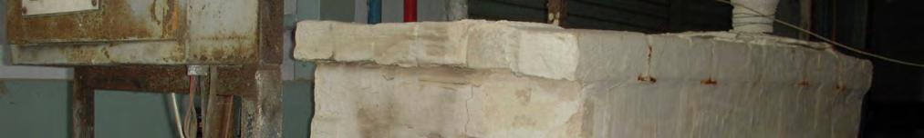
39 OD pipe at the top, one for delivering hot fluid containing vapor into the Chamber coming from evaporator through a 2" (5.1 cm) OD pipe at the mid section, one for entering preheated feed through a ½" (1.27 cm) OD pipe near the bottom conical section from one side and one for discharging the concentrated solution through a ½" (1.27 cm) OD pipe at the bottom of the conical section. Provisions were made for attaching a level indicator at the bottom, a pressure gauge at the top and thermocouples at various sections of the flash chamber. Reinforcement rods were welded at two points inside the cylindrical portion of the Chamber to ensure strength. The major dimensions of the cylindrical section were: 1.25' (0.38 m) diameter and 5'(1.52 m) length while those for the conical section were: 1.25' (0.38 m) diameter and 1.5' (0.46 m) length. The Chamber was made of 2mm thick SS 304 sheet. The total volume of the Chamber, excluding the top hemispherical section was 6.96 ft 3 (0.197 m 3 ) (cylindrical section: 6.33 ft 3 (0.179 m 3 ) and conical section 0.63 ft 3 (0.018 m 3 ). The Flash Chamber was lagged with asbestos rope and tape Preheater This was a horizontal shell and tube heat exchanger as shown in Figure 4.5. It consisted of 4-2.5' (0.762 m) long ½" (1.27 cm) OD 0.02'' (0.05 cm) thick SS 304 tubes, contained in a 3" (7.62 cm) OD carbon steel shell. The tube sheets were made out of ¼" (0.64 cm) thick SS 304 sheet. Total heat transfer area was m 2. The shell had two 2" (5.1 cm) OD carbon steel pipes to serve as inlet and outlet nozzles for steam and condensate respectively. The two channels on either side of the shell were made of 3.5'' (8.9 cm) OD SS 304 pipes enclosed with 5" (12.7 cm) diameter ¼'' (0.64 cm) thick SS 304 sheets. Both channels had ½'' (1.27 cm) OD SS pipes to serve as inlet and outlet nozzles for the caustic soda solution. The exchanger was lagged with asbestos rope and tape Natural Gas Fuelled Furnace The Furnace was constructed with firebricks covered with fireclay, housing a burner fuelled by natural gas, Figure 4.6. The external dimensions of the Furnace were 4.75' 2.9' 2.1' (1.45 m 0.88 m 0.64 m) and the wall thickness was 3'' (7.62 cm). The 26
40 burner was located outside the brick wall at one end of the Furnace and consisted of a blower that drew air from the surroundings and mixed it with natural gas drawn from the supply line. Once ignited, the burner burnt the natural gas inside the Furnace. The burner was provided with an electric spark type ignitor along with a flame detector. A 4" (10.2 cm) CS pipe was inserted on the top surface near the opposite end of the burner. Flue gases produced by the combustion flew out of the Furnace through this pipe. The flow of natural gas was controlled using a valve Circulation Pump This was a 0.5 hp SS Centrifugal Pump with inlet nozzle of ¾'' (1.9 cm) OD and outlet nozzle of ½'' (1.27 cm) OD Blower This was a 2.5 hp, 2800 r.p.m. Centrifugal Blower with 2'' (5.1 cm) OD inlet nozzle and 6'' (15.24 cm) OD outlet nozzle Feed Tank This was a vertical cylinder with a hemispherical bottom, Figure 4.7. There was a smaller cylindrical section at the bottom of the hemispherical section. This cylindrical section had a 7.1" (18 cm) circular disc made of SS 304 attached to the bottom. The disc housed a ¾" (1.9 cm) OD outlet pipe. All sections were made of SS 304. The total volume of the Feed Tank was 3 ft 3 (0.085 m 3 ) excluding the hemispherical section (Larger cylindrical section: 2.99ft 3 (0.085 m 3 ), smaller cylindrical section: 0.01ft 3 (0.0003m 3 )) Product Tank This was a 19.7" (50cm) ID vertical cylinder of 29.5" (75 cm) height with a conical bottom as shown in Figure 4.8. The conical portion had a vertical height of 1.97" (5cm). There was a smaller cylindrical section at the bottom of the conical section with dimensions of 3.94" (10cm) diameter and 2.76" (7cm) height. This cylindrical section 27
41 had an 18 cm circular disc attached to the bottom. The disc housed a ½" (0.2 cm) OD outlet pipe. A ½" (0.2 cm) OD overflow pipe is inserted on one side near the top. All sections were made of SS 304. The total volume of the Product Tank was 5.22 ft 3 (0.148 m 3 ) excluding the hemispherical section (Larger cylindrical section: 5.21ft 3 ( m 3 ), smaller cylindrical section: 0.01ft 3 ( m 3 )). Photographs of the experimental setup and the major components of the setup are shown in Figures 4.2 and 4.9 through
42 Feed Vent PREHEATER FEED TANK Vent Steam BLOWER Flue Gas Out EVAPORATOR FLASH CHAMBER Condensate out Flue Gas In Natural Gas NATURAL GAS FIRED FURNACE PRODUCT TANK Air CENTRIFUGAL PUMP Drain Figure 4.1: Process Flow Diagram 29


43 Figure 4.2: Photograph of the experimental setup 30
44 6" (15.2 cm) 4.5" (11.4 cm) ¼ (0.64 cm)thick SS Sheet 4.5" (11.4 cm) OD SS Pipe 6" 6" (15.2 cm) 6" 2" (2.51 cm) OD SS Pipe 2" (5.1 cm) OD Carbon Steel Pipe 4" (10.2 cm) OD Carbon Steel Shell ½ (1.27 cm) OD SS Tubes 5' (1.52 m) Packing Shorter nut with hole drilled through Thread Thermocouple Nut with hole drilled through 2" (5.1 cm) OD Carbon Steel Pipe ½ ( 1.27 cm) OD SS Pipe ¼ Thick SS Tube Sheet 4" 6" ½ OD SS Tubes Figure 4.3: Evaporator 31
45 Figure 4.4: Flash Chamber 32
46 ½ (1.27 cm) OD SS Pipe 6" 6" 2" (5.1 cm) OD Carbon Steel Pipe 6" (15.2 cm) 2'-6" (0.76 m) 5" (12.7 cm) 3.5" (8.9 cm) ¼ (0.64 cm) Thick SS Sheet 3.5" (8.9 cm) OD SS Pipe 3" (7.6 cm) OD Carbon Steel Shell ½ (1.27 cm) OD SS Tubes 2" (5.1 cm)) OD Carbon Steel Pipe Packing Shorter nut with hole drilled through ¼ Thick SS Tube Sheet ½ OD SS Tubes 3" (7.62 cm) 5" (12.7 cm) Thread Nut with hole drilled through Thermocouple Figure 4.5: Preheater 33
47 Figure 4.6: Natural Gas Fuelled Furnace 34
48 Figure 4.7: Feed Tank Figure 4.8: Product Tank 35


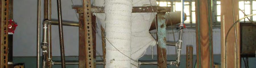


49 Figure 4.9: Photograph of the Evaporator 36

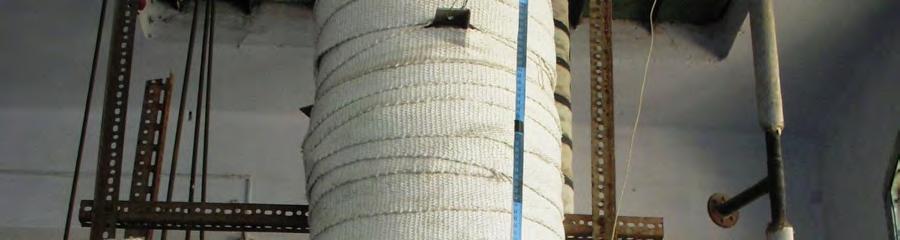


50 Figure 4.10: Photograph of the Flash Chamber 37


51 Figure 4.11: Photograph of the Preheater 38


52 ` Figure 4.12: Photograph of the Natural Gas Fuelled Furnace 39
Changing mercerising waste water into money. Caustic recovery for mercerising lye
 Changing mercerising waste water into money Caustic recovery for mercerising lye The Körting Caustic Recovery Plant (CRP) During the mercerising process the diluted caustic soda (weak lye) from the stabilisation
Evaporation is a special case of heat transfer to a boiling liquid.
 Evaporator Evaporation is a special case of heat transfer to a boiling liquid. Evaporation occurs at the liquid vapor interface when the vapor pressure is less than the saturation pressure of the liquid
Evaporation System: Types and Design Aspects
 Evaporation System: Types and Design Aspects Dr. Pankaj Kumar, Er. Dhritiman Saha and Er. Chandan Solanki Food Grains and Oil Seeds Processing Division, ICAR-CIPHET, Ludhiana Evaporation is an important
Boiler Basics. Design and operation
 Boiler Basics Design and operation A boiler is an enclosed vessel that provides a means for combustion heat to be transferred into water until it becomes heated water or steam. The hot water or steam under
TABLE OF CONTENTS. SI No Contents Page No.
 TABLE OF CONTENTS SI No Contents Page No. 1 Basic Wet Processing Terms 1 2 Sequence of operations in Wet processing 2 3 Brief note about Continuous bleaching Range 3 4 Details of Continues Bleaching Range
By:- ASMA PARVEEN Department of Industrial Chemistry Brahmanand College, Kanpur
 By:- ASMA PARVEEN Department of Industrial Chemistry Brahmanand College, Kanpur Evaporation Objective: To concentrate a dilute solution consisting of non volatile solute and volatile solvent In this operation,
TABLE OF CONTENTS. SI No Contents Page No.
 TABLE OF CONTENTS SI No Contents Page No. 1 Basic wet Processing Terms 2 2 Sequence of operations in Wet processing 3 3 Brief Note on Stenter machine 4 4 Details of stenter machine 4 5 Operating stenter
TMCI Padovan Evaporators
 TMCI Padovan Evaporators Evaporators Our range includes 4 types of evaporators: Forced Circulation Falling Film Evaporators Plates Thin Film Concentration systems Evaporator choosing criteria: product
Mercerizing Solutions. Woven Line
 Mercerizing Solutions Woven Line Processes Leader in wet textile finishing Washing Solutions Bleaching Solutions Resource Management Mercerizing Solutions Dyeing Solutions BEN-DIMENSA Highest quality mercerizing
IN THE PULP AND PAPER INDUSTRY
 H E A T E X C H A N G E R S BULLETIN NO. TIS-105A PRIME SURFACE PLATE & FRAME ALL-WELDED PLATE IN THE PULP AND PAPER INDUSTRY THE heat transfer people H E A T E X C H A N G E R S 2 TRANTER BRINGS EFFICIENCY
Evaporation The process in which a liquid dissipates or emits vapor, fumes, or invisible minute particles.
 35 Evaporation of waste wash water occurs during normal operation of the pressure, steam or automatic vehicle wash system. It is generally assumed that 10-30% of wash water is lost to evaporation. Accelerated
FS 231: Final Exam (5-6-05) Part A (Closed Book): 60 points
 Part A (Closed Book): 60 points") Name: Start time: End time: FS 231: Final Exam (5-6-05) Part A (Closed Book): 60 points 1. What are the units of the following quantities? (10 points) a. Enthalpy of a refrigerant b. Dryness fraction of
Name: Start time: End time: FS 231: Final Exam (5-6-05) Part A (Closed Book): 60 points 1. What are the units of the following quantities? (10 points) a. Enthalpy of a refrigerant b. Dryness fraction of
For inspection purposes only.
 Attachment F.1 Neutralisation System Process Description The CPG process generates both acid and caustic waste water from the acid/base leaching processes. This waste water will be collected in dedicated
Boiler. Fire tube Boiler:
 Boiler What is Boiler? A closed metallic vessel in which the water is heated beyond the boiling temperature by the application of heat by the combustion of fuels to convert it into steam. The function
Volume 10 Summer Understanding Terminology Key to Treatment Program Success
 Volume 10 Summer 2003 Understanding Terminology Key to Treatment Program Success One of the keys to success of a boiler water treatment program is good communication between the water treatment professional
The Ultimate in Direct Contact Water Heating. by Thermal Engineering of Arizona, Inc. An Inc. 500 Company
 SWERHMTER The Ultimate in Direct Contact Water Heating - by Thermal Engineering of Arizona, Inc. An Inc. 500 Company TEA'S "S U P E R H E ATE R" When high volumes of hot water are needed, Thermal Engineering's
Thermal Fluid Heaters
 Thermal Fluid Heaters Vertical Coil, Vertical Tubeless, Electric and Horizontal Sizes from 75,000 to 40,000,000 BTU/HR The heat transfer innovators. THERMAL FLUID FEATURES AND BENEFITS KEY FEATURES No
HOW TO SELECT AN INDIRECT THERMAL TECHNOLOGY FOR INDUSTRIAL MATERIALS PROCESSING
 white paper HOW TO SELECT AN INDIRECT THERMAL TECHNOLOGY FOR INDUSTRIAL MATERIALS PROCESSING Better Thermal Processing Results Begin with Selecting the Right Technology Authored by Rob Grady Director of
S&T HEAT EXCHANGERS Part II: Main Parts, Conical Transitions, Shell & Heads, Nozzle Design.
 S&T HEAT EXCHANGERS Part II: Main Parts, Conical Transitions, Shell & Heads, Nozzle Design. STUDY NOTES Instructor: Javier Tirenti training@arvengconsulting.com www.arvengconsulting.com Table of contents
CHAPTER 8 EVAPORATION. The basic factors that affect the rate of evaporation are the:
 CHAPTER 8 EVAPORATION Frequently in the food industry a raw material or a processed food contains more water than is required in the final product. When the foodstuff is a liquid, the easiest method of
International Association of Certified Practicing Engineers
 www.iacpe.com Knowledge, Certification, Networking Page: 1 51 IACPE No 19, Jalan Bilal Mahmood 80100 Johor Bahru Malaysia The International is providing the introduction to the Training Module for your
Performance Analysis of Li-Br Water Refrigeration System with Double Coil Anti-Swirl Shell and Coil Heat Exchangers
 e-issn 2455 1392 Volume 2 Issue 5, May 2016 pp. 108-116 Scientific Journal Impact Factor : 3.468 http://www.ijcter.com Performance Analysis of Li-Br Water Refrigeration System with Double Coil Anti-Swirl
a. CFCs. b. HCFCs. c. Pressurized nitrogen. d. Compressed dry air. 17. The state of the refrigerant leaving the condenser of a refrigeration system
 Core 1. Ozone in the stratosphere above the earth consists of: a. Molecules containing 3 oxygen atoms. b. Molecules of 2 oxygen atoms. c. Radioactive particles. d. Pollutants that have risen from ground
Evaporation Technology
 FENIX Evaporation Technology ENGINEERING-EQUIPMENT-TURNKEY SYSTEMS FALLING FILM EVAPORATOR FORCED CIRCULATION EVAPORATOR MULTIPLE EFFECT EVAPORATOR AGITATED THIN FILM EVAPORATOR SHORT PATH DISTILLATION
Air Conditioning Clinic. Absorption Water Chillers One of the Equipment Series TRG-TRC011-EN
 Air Conditioning Clinic Absorption Water Chillers One of the Equipment Series TRG-TRC011-EN Absorption Water Chillers One of the Equipment Series A publication of The Trane Company Worldwide Applied Systems
Division Textile. Vacuum. Technology
 Division Textile Vacuum Technology Vacuum Technology The Principle Evac systems integrated into open-width textile ranges will improve fabric quality, increase production speed, significantly lower production
VAPOUR RECOVERY DURING FUEL LOADING. Ben Adamson Principal Engineer Refrigeration Engineering Pty Ltd, NSW Australia
 VAPOUR RECOVERY DURING FUEL LOADING Ben Adamson Principal Engineer Refrigeration Engineering Pty Ltd, NSW Australia ben_adamson@refeng.com.au ABSTRACT Volatile fuels such as gasoline and naphtha, and to
Investigation of Multiple Effect Evaporator Design
 2017 Published in 5th International Symposium on Innovative Technologies in Engineering and Science 29-30 September 2017 (ISITES2017 Baku - Azerbaijan) Investigation of Multiple Evaporator Design * 1 Kemal
EVERCION P & PRINTING TECHNICAL INFORMATION
 EVERCION P & PRINTING TECHNICAL INFORMATION 14.10.2015 PRINTING Laboratory Sample Lab Printing Dye Kitchen Designing Mold (Şablon) Department Planning Printing Printing Machine Evercion P Evercion P reactive
Presentation On Industrial Boiler Operation And Maintenance
 Presentation On Industrial Boiler Operation And Maintenance Supervised By: Engr. Poresh Kanti Das GM-MAL RIP, Mulgoan, Kaligonj, Gajipur Boiler fundamental. Assessment On Heat recovery Boiler. Boiler Operation.
Shyam Enterprises 9 PACKAGE UNIT
 Shyam Enterprises 9 PACKAGE UNIT 59 Reaction Distillation Unit The Unit has been designed to suit the customers requirement of combination of versatile reaction/distillation or combination for pilot plant
Problem Cause Remedial action. Gauge glass There was excess chemical dosage The normal ph recommended was 9.5 to See photo 3 & 4.
 CASE STUDIES OF STEAM SYSTEM AUDIT IN SOME PLANTS By K.K.Parthiban, Venus Energy Audit System Introduction This article outlines the outcome of auditing of steam system conducted in process Industries.
Refrigeration Systems and Accessories
 As with the Chapter Review Tests and the Final Exam, the tests your understanding of the materials underlying the learning objectives. After you ve reviewed your answers to the Chapter Review Tests, try
TABLE OF CONTENTS. SI No Contents Page No.
 TABLE OF CONTENTS SI No Contents Page No. 1 Basic wet Processing Terms 1 2 Sequence of operations in Wet processing 2 3 Brief Note on calendering 3 4 Details of calendering machine 4 5 Operating calendering
Efficient Steam System Design
 Efficient Steam System Design The word Efficient is often used to describe the general performance of a system. However it is important to distinguish between efficiency and effectiveness. Efficiency is
Experimental investigation of Hybrid Nanofluid on wickless heat pipe heat exchanger thermal performance
 Experimental investigation of Hybrid Nanofluid on wickless heat pipe heat exchanger thermal performance #1 Jaydev S. Bade, #2 Dr. Nitin U. Korde 1 Department of Mechanical Engineering, Savitribai Phule
MES COURSE MODULE IN TEXTILES CHEMICAL PROCESSING
 MES COURSE MODULE IN TEXTILES CHEMICAL PROCESSING 1. Module Name Effluent Water Treatment plant operator 3. Code TCP 701 would be able to operate the Effluent treatment plant and discharge water of permitted
DEHYDRATION AND DESALTING
 DEHYDRATION AND DESALTING Wet Crude Oil Crude oil from a GOSP may contain very small droplets of salty water Many of these droplets are held in suspension by a thin film of oil that surrounds them. These
CHAPTER 6. HEATING PRODUCTION EQUIPMENT AND SYSTEMS
 CHAPTER 6. HEATING PRODUCTION EQUIPMENT AND SYSTEMS 6.1 Types of Heating Systems 6.2 Heating Energy Sources 6.3 Furnaces and Air Heaters 6.4 Boilers 6.5 District Heating 6.6 Selection of Medium- Steam
Heat Exchanger. The purpose may be either to remove heat from a fluid or to add heat to a fluid.
 HEAT EXCHANGERS Heat Exchanger Heat exchanger is an apparatus or an equipment in which the process of heating or cooling occurs. The heat is transferred from one fluid being heated to another fluid being
Care and Cleaning Recommendations for Mount Vernon FR Flame Resistant Fabrics
 Mount Vernon Mills, Inc. 91 Fourth St. Trion, GA 30753 (706) 734-2311 www.mvmfr.com mvmfr@mvmills.com Care and Cleaning Recommendations for Mount Vernon FR Flame Resistant Fabrics Mount Vernon Mills, Inc.
CHAPTER 7 PERFORMANCE ANALYSIS OF VAPOUR COMPRESSION REFRIGERATION SYSTEM IN HYBRID REFRIGERATION SYSTEM
 111 CHAPTER 7 PERFORMANCE ANALYSIS OF VAPOUR COMPRESSION REFRIGERATION SYSTEM IN HYBRID REFRIGERATION SYSTEM 7.1 INTRODUCTION Energy is the primary component to run any system in the world. According to
DRAFT. Electroplating Tip Sheet Drag-Out Reduction. Background
 Electroplating Tip Sheet Drag-Out Reduction Electroplating Tip Sheet Series 1. Good Operating Practices 2. Drag-Out Reduction 3. Rinse Water Reduction 4. Recovery and Recycling of Bath Chemicals Background
STATIC MIXERS STATIC MIXING HEAT EXCHANGERS EJECTORS IN-LINE HEATER IN-TANK HEATER JET MIXING EDUCTOR DESUPERHEATER
 SAMHWA Mixing Technology Co., Ltd. STATIC MIXERS STATIC MIXING HEAT EXCHANGERS EJECTORS IN-LINE HEATER IN-TANK HEATER JET MIXING EDUCTOR DESUPERHEATER STATIC MIXERS Samhwa static mixers provide continuous
Keywords biomass boiler, biomass resource, Small scale sewage treatment plant, twin drum type dryer,
 Practical Research on a Sewage Sludge Fuelization System for Small-scale Sewage Treatment Plants Eiji Tochioka 1,Hidekazu Nagasawa 1, Shuichi Ochi 1 Tsuneo Nishida 2, Kazuya Hibino 2 1 Japan Institute
Descaler & Prevention
 Descaler & Prevention Treatment Method for existing scaled surfaces like inside of piping, tubes, Heaters, boilers, sump wall etc. By Deepak Chopra Watch Water GmbH Fahrlachstraße 14 68165 Mannheim Germany
5 Separation Processes
 5 Separation Processes 5.1 Distillation 1 Distillation separates chemicals by the difference in how easily they vaporize. The two major types of classical distillation include continuous distillation and
Prepared by Technical Team
 Prepared by Technical Team Summary Vacuum degassing (VD) and vacuum oxygen de-carburisation (VOD) are the main processes in secondary steel making. The large volumes of dissolved contaminant gases arising
The theory behind heat transfer
 Alfa Laval in brief Alfa Laval is a leading global provider of specialized products and engineered solutions. Our equipment, systems and services are dedicated to helping customers to optimize the performance
WHITE PAPER The Importance of Rinsing in Metal Finishing Operations
 WHITE PAPER The Importance of Rinsing in Metal Finishing Operations By Steve Rudy, CEF & Sales/Technical Representative The focus or driving force of rinsing is to eliminate contaminants from the surface.
Paper No. : 04 Paper Title: Unit Operations in Food Processing Module- 14:Evaporation
 Paper No. : 04 Paper Title: Unit Operations in Food Processing Module- 14:Evaporation 14.1 Introduction Evaporation is a common unit operation in food processing industries in which partial removal of
Crown Iron Works Company
 Crown Iron Works Company AOCS FUNDAMENTALS OF OILSEED AND EDIBLE OIL PROCESSING AND REFINING Fundamentals of Oils and Fats Processing- Deodorizer Design and Optimization Shanghai, China 17-18 November
How is the heat transfer?
 How is the heat transfer? As we discussed early in the first chapter that heat can transfer through materials and the surrounding medium whenever temperature gradient exists until thermal equilibrium is
TYPE.005 DA-2C. Deaerating Boiler Feed Pumps. SHIPCO Deaerators can save you money!!! BULLETIN 149 Revised 8/09
 SHIPPENSBURG PUMP CO., INC. P.O. BOX 279, SHIPPENSBURG, PA 17257 PHONE 717-532-7321 FAX 717-532-7704 WWW.SHIPCOPUMPS.COM BULLETIN 149 Revised 8/09 TYPE.005 DA-2C Deaerating Boiler Feed Pumps SHIPCO Deaerators
MECHANICAL ENGINEERING ME.2017 FUNDAMENTAL OF REFRIGERATION AND AIR CONDITIONING. Sample Questions and Answers
 MECHANICAL ENGINEERING ME.2017 FUNDAMENTAL OF REFRIGERATION AND AIR CONDITIONING Sample Questions and Answers CHAPTER 5 EVAPORATORS 1. What is Evaporator? Classify the various types of evaporator. Evaporator
PIPING SYSTEM EQUIPMENTS
 PIPING SYSTEM EQUIPMENTS Introduction Equipments are devices that provide power, process and store materials. Equipments in piping systems depend on the specific industries using them. Specialized equipment
Evaporation studied on a duplicated vessel, pilot scale evaporator equipped with a heat pump
 Evaporation studied on a duplicated vessel, pilot scale evaporator equipped with a heat pump 1. Theory In a steam-heated concentrator temperature changes with the location in the vessel because of the
Vacuum Booster for Distillation Process
 Vacuum Booster for 1.00 Introduction: Distillation at reduced pressures is a widely used process in the chemical industry, specially used in extraction / purification of essential oils, deodorisation of
Solution of I Mid Term Steam Engineering 6ME5A
 1(a) Discuss the working principle of LaMont high pressure boiler This boiler works on basic principle of forced convection. If the water is circulate by a pump inside the tube, the heat transfer rate
PERFORMANCE OF FORCED CONVECTION EVACUATED TUBE SOLAR GRAIN DRYER. BOOKER ONYANGO OSODO B. Ed.(TECH); M. Phil (Tech. Ed) (J98/25749/2011)
; M. Phil (Tech. Ed) (J98/25749/2011)") PERFORMANCE OF FORCED CONVECTION EVACUATED TUBE SOLAR GRAIN DRYER BOOKER ONYANGO OSODO B. Ed.(TECH); M. Phil (Tech. Ed) (J98/25749/2011) A research Proposal Submitted in Partial Fulfillment of the Requirements
PERFORMANCE OF FORCED CONVECTION EVACUATED TUBE SOLAR GRAIN DRYER BOOKER ONYANGO OSODO B. Ed.(TECH); M. Phil (Tech. Ed) (J98/25749/2011) A research Proposal Submitted in Partial Fulfillment of the Requirements
Reactor-Boiler and Auxiliaries - Course 433 BOILER STEAM AND WATER SYSTEMS
 Lesson 433.60-1 Reactor-Boiler and Auxiliaries - Course 433 BOILER STEAM AND WATER SYSTEMS It was noted in an earlier lesson, that the reactor is a source of heat, and serves the purpose of a "furnace"
Introduction to Control Technology
 Chapter 13 Introduction to Control Technology Introduction to Control Technology Carbon adsorption Incineration Condensation Bioreaction Carbon Adsorption 13-1 Activated Carbon A class of materials Produced
Adca Training. Part 2
 Adca Training Part 2 This presentation is only a guideline, that can only be completed by a trained personnel. (This document s total or partial use and/or reproduction is only allowed if the reference
Responsible Care Product Stewardship for Refrigerants
 1 ABSTRACT Responsible Care Product Stewardship for Refrigerants Christoph Meurer; Ewald Preisegger Solvay Fluor und Derivate GmbH Hans-Böckler-Allee 20 30161 Hannover Germany Product stewardship summarizes
9707 Key West Avenue, Suite 100 Rockville, MD Phone: Fax:
 9707 Key West Avenue, Suite 100 Rockville, MD 20850 Phone: 301-740-1421 Fax: 301-990-9771 E-Mail: awt@awt.org Part of the recertification process is to obtain Continuing Education Units (CEUs). One way
Trade of Plumbing. Module 2: Domestic Hot and Cold Water Service Unit 10: Hot Water Supply Phase 2
 Trade of Plumbing Module 2: Domestic Hot and Cold Water Service Unit 10: Hot Water Supply Phase 2 Table of Contents List of Figures... 4 List of Tables... 5 Document Release History... 6 Module 2 Domestic
LAUNDRY GUIDE. Bedding. Textile solutions for a better guest experience
 LAUNDRY GUIDE Bedding Textile solutions for a better guest experience Contents 1 Introduction 2 Detergent Selection 2 Washing 3 Bleach 4 Anti-chlor 4 Souring 4 Rinsing 5 Fluorescent Whitening Agents &
Fig.: macroscopic kinetic energy is an organized form of energy and is much more useful
 Harnessing Energy Fig.: macroscopic kinetic energy is an organized form of energy and is much more useful Vapor Power Cycle The vast majority of electrical generating plants are variations of vapor power
Top performance when the going gets tough
 Top performance when the going gets tough The Alfa Laval DuroShell plate-and-shell heat exchanger Sub-headline coming soon DuroShell plate-and-shell made tougher Alfa Laval DuroShell is a specially engineered
Heat Dissipation in Control Panel using Heat Pipe
 ISSN (e): 2250 3005 Volume, 07 Issue, 10 October 2017 International Journal of Computational Engineering Research (IJCER) Heat Dissipation in Control Panel using Heat Pipe Karan Hingmire 1 1 B.E mechanical,
OPTIMISE VACUUM TO IMPROVE PLANT PERFORMNCE
 OPTIMISE VACUUM TO IMPROVE PLANT PERFORMNCE Vacuum Pumps and systems are widely used in the chemical process industry for various applications such as drying, solvent recovery, distillation, short path
Dissolving Pulp From Cotton Linters BASIC INFORMATION. IPS Engineering
 Dissolving Pulp From Cotton Linters BASIC INFORMATION End use & end products Manufacturing Process Product Segment End Use Etherification Ethers Binders CMC Detegents Food Pharmacy Oil driling mud DISSOLVING
CHAPTER I INTRODUCTION. In the modern life, electronic equipments have made their way
 1 CHAPTER I INTRODUCTION In the modern life, electronic equipments have made their way in to practically every part, which is from electronic gadgets to high power computers. Electronic components have
BASIC BOILERS NAME :- DATE :-
 BASIC BOILERS NAME :- DATE :- This examination was conducted under conditions that allowed a fair and honest test of the candidate s knowledge and ability. Exam supervisor C:\Tassie Steam\N01basicboiler
Performance Enhancement of Refrigeration Cycle by Employing a Heat Exchanger
 Performance Enhancement of Refrigeration Cycle by Employing a Heat Exchanger Abstract Shoeb J. Inamdar 1 H.S. Farkade 2 M. Tech student. (Thermal Engineering) 1, Asst. Professor 2 Department of Mechanical
Waste-heat recovery: Weighing in the environmental Factor
 Waste-heat recovery: Weighing in the environmental Factor Engineer's Digest Magazine August 1989 Richard P. Zoldak, P.E. Market Development Manager Alfa-Laval Thermal Co. Thermal pollution and process-waste
OIL MIGRATION IN R-12 & R-22 SYSTEMS By: Norman Sharpe Professor, Air Conditioning & Refrigeration Dept., California State Polytechni College
 Service Application Manual SAM Chapter 630-34 Section 1M OIL MIGRATION IN R-12 & R-22 SYSTEMS By: Norman Sharpe Professor, Air Conditioning & Refrigeration Dept., California State Polytechni College INTRODUCTION
ecodry Figure 1 - Process Diagram ecodry B General Process Description
 ecodry The process principal of the ecodry system is centered around the concept of drying in a closed steam loop, with a process-integrated thermal oxidation. The separation of flue gas from the drying
OPERATION OF LAFER SOLVENT SCOURING PLANT
 OPERATION OF LAFER SOLVENT SCOURING PLANT INDEX Operation principle... page 2 Machine attachments... page 3 Plant service s... page 4 Machine start-up and stop... page 5 Safety systems of plant... page
Komline-Sanderson Paddle Dryer. Drying technology for biosolids, sludges and by-products
 Komline-Sanderson Paddle Dryer Drying technology for biosolids, sludges and by-products Why dry? There are economic and environmental benefits to drying biosolids, sludges and by-products. In municipal
AIM OF THE EXPERIMENT:- Study of boilers (fire tube, water tube) APPARATUS REQUIRED: - SL.NO NAME OF THE APPARATUS SPECIFICATION QUANTITY 01 Fire tube
 APPARATUS REQUIRED: - SL.NO NAME OF THE APPARATUS SPECIFICATION QUANTITY 01 Fire tube") LABORATORY MANUAL ON STUDY OF FIRE TUBE AND WATER TUBE BOILERS Prepared By Prof. (Dr.) M. K. Roul Professor and Principal, Gandhi Institute for Technological Advancement (GITA), Bhubaneswar 752054 June
LABORATORY MANUAL ON STUDY OF FIRE TUBE AND WATER TUBE BOILERS Prepared By Prof. (Dr.) M. K. Roul Professor and Principal, Gandhi Institute for Technological Advancement (GITA), Bhubaneswar 752054 June
TEMPLATE ASSISTED CRYSTALLIZATION. Presented By Ryan Lessing 11/13/2014
 TEMPLATE ASSISTED CRYSTALLIZATION Presented By Ryan Lessing 11/13/2014 Different Forms of Hardness in Water Calcium and Magnesium Bicarbonate- This is what is referred to as temporary hardness. Once it
Heat Pipe Applications Introduce
 Heat Pipe Applications Introduce Most suitable where: Low humidity level necessary Humidity control required Air reheated after cooling in traditional HVAC system Large quantities of ventilation air needed
Math. The latent heat of fusion for water is 144 BTU s Per Lb. The latent heat of vaporization for water is 970 Btu s per Lb.
 HVAC Math The latent heat of fusion for water is 144 BTU s Per Lb. The latent heat of vaporization for water is 970 Btu s per Lb. Math F. to C. Conversion = (f-32)*(5/9) C. to F. Conversion = C * 9/5 +
ANNEX 6. Refinery No. 1 New Area. Problems Existing in the Current Condensate Return System of the New Area of Refinery No.1
 ANNEX 6 In FP the project was divided in two phases, but due to financial difficulties, Phase II is still not implemented. Below is what happened in Phase I of the Project, which will be replicated in
BOILER SYSTEM CHEMICAL TREATMENT 101
 BOILER SYSTEM CHEMICAL TREATMENT 101 The primary function of a boiler is to transfer heat from hot gases generated by the combustion of fuel into water until it becomes hot or turns to steam. The steam
GESTRA Information A 1.7
 Issue Date: 9/06 GESTRA Systems GESTRA Information A 1.7 Automatic Deaeration of -Heated Heat Exchangers Preface For optimum efficiency of steam-heated heat exchangers several requirements should be fulfilled,
HYBRID ADIABATIC Cooling System
 Blending Conveying Drying Process Cooling Heat Transfer Size Reduction HYBRID ADIABATIC Cooling System Water & Energy Savings Low Maintenance Improved Health & Safety Hybrid design combines dry cooler
Development of Boiler Design
 Development of Boiler Design Learning Outcome When you complete this module you will be able to: Discuss historical developments of, and the general requirements for proper boiler design. Learning Objectives
Experimental Investigation of a Hybrid Evacuated Tube Solar Collector
 International Conference on Mechanical, Industrial and Materials Engineering 2015 (ICMIME2015) 11-13 December, 2015, RUET, Rajshahi, Bangladesh Paper ID: ET-46 Experimental Investigation of a Hybrid Evacuated
AUTOMATION OF BOILERS USING LABVIEW
 I J L S C M 4(1), 2012, pp. 49-53 AUTOMATION OF BOILERS USING LABVIEW A. MICHAEL SIDDHARTHA AND S. NAVEEN KUMAR Under Graduate Student, Department of Electronics and Communication Engineering Thiagarajar
PARTS CLEANING AND DEGREASING
 Important Note: The following text is excerpted directly from the New York State Department of Environmental Conservation s publication, Environmental Compliance, Pollution Prevention, and Self Assessment
Technical Illustration of Condensate Formation
 Condensate Recovery As hot steam cools down inside a mill s pipes, the droplets of vapor turn into condensate water. If recycled, this condensate water can provide mills with an inexpensive source of clean
CHAPTER 3 BASIC STEAM CYCLE
 CHAPTER 3 BASIC STEAM CYCLE To understand steam generation, you must know what happens to the steam after it leaves the boiler. A good way to learn the steam plant on your ship is to trace the path of
Evaporation Technology
 FENIX Evaporation Technology ENGINEERING-EQUIPMENT-TURNKEY SYSTEMS FALLING FILM EVAPORATOR FORCED CIRCULATION EVAPORATOR MULTIPLE EFFECT EVAPORATOR AGITATED THIN FILM EVAPORATOR SHORT PATH DISTILLATION
To Compliance and Beyond. Valley Chrome Plating s Journey to Zero Discharge
 To Compliance and Beyond Valley Chrome Plating s Journey to Zero Discharge Valley Chrome Manufacturer of Truck Bumpers since 1961 Decorative Chrome Plating 1st Plating Shop in U.S. to be permitted for
Chapter 2.3: Steam System
 Part I: Objective type Questions and Answers Chapter 2.3: Steam System 1. For industrial process heating, the best quality of steam is: a) dry saturated steam b) superheated steam c) wet steam d) high
International Reactor Bulletin 1100 Corporation. Standard and Custom Reactors for the Chemical Process Industries
 International Reactor Bulletin 1100 Corporation Standard and Custom Reactors for the Chemical Process Industries 2 International Reactor Corporation 521 Kiser Street Dayton, Ohio 45404-1641 Phone: 937-224-4444
Development Centre for Evaporation and Thermal Separation Technologies
 Development Centre for Evaporation and Thermal Separation Technologies The Pilot Plant of GIG Karasek Our Company In Europe, GIG Karasek is a leading manufacturer in the field of system and apparatus construction
Theory of Operation: How Parts Cleaning Works
 Theory of Operation: How Parts Cleaning Works MART defines the term to clean as to overpower the soils. The MART Parts Washer is a high-impact pressure, high-temperature, industrial water-based cleaning