UCS 240 CONDENSING GAS FIRED BOILER
|
|
|
- Hollie Wilkinson
- 5 years ago
- Views:
Transcription

1 UCS 240 CONDENSING GAS FIRED BOILER
2 CONTENTS : INSTALLATION, OPERATION, AND MAINTENANCE MANUAL ( ) MULTIPLE BOILER WIRING GUIDE ( ) HEAT EXCHANGER CLEANING INSTRUCTIONS ( ) REQUIRED INSPECTION SPECIAL ( ) BACK COVER


3 CONDENSING GAS FIRED FLOOR OR WALL MOUNTED BOILER INSTALLATION, OPERATION & MAINTENANCE MANUAL Model UCS-240 Manufactured by: ECR International Inc Dwyer Avenue, Utica, NY Tel PN REV. E [07/30/2018]


")


4 VERIFY CONTENTS RECEIVED Fully Assembled Boiler Metal Wall Bracket Safety Relief Valve (Maximum 50 PSI) Temperature Includes essential documents. Drain Valve Gas Shutoff Valve TP Gauge and Safety Relief Valve Connections Document Package Used for measuring outside temperature Used for connecting condensate piping to boiler Outdoor Sensor Condensate Drain Connections 2
5 TABLE OF CONTENTS 1 - Important Information Introduction Component Listing Locating Boiler Hydronic Piping General Special Conditions Safety Relief Valve And Air Vent Low Water Cutoff Trim Piping System Piping Heating System And Refrigeration Manifold Installation (Supplied) Combustion Air And Vent Piping General Removal Of Existing Boiler From Common Vent System Definitions Approved Venting Materials Coaxial Twin Pipe Polypropylene And CPVC Systems Venting Configurations Side Venting Terminal Requirements Multiple Boiler Venting - General Multiple Boiler Venting - Mounting Multiple Boiler Venting - Layout Multiple Boiler Venting - Parameter Settings Condensate Piping Gas Supply Piping General LP Conversion Leak Check Gas Piping Electrical Connections General Electric Knockouts Electrical Connections Access To Connection Block Main Supply Connection Shutdown Input Release Input Optional Electrical Connections: Outdoor Temperature Sensor Central Heating Thermostat DHW Indirect Water Heater Frost Protection Start Up Procedure Fill Condensate Trap With Water Commission Setup (Water) Commission Setup (Gas) Commission Setup (Electric) Control Panel Deaeration Function Commissioning Before Gas Conversion Gas Conversion (Propane) Combustion Setup (High-Fire) Combustion Setup (Low-Fire) Operational Check User Level Parameters Installer Level Parameters Parameters Settings Reading Measured Values Status And Sub-Status Return To The Factory Settings: Operating Instructions Sequence Of Operation Operating Instructions To Turn Off Gas To Appliance General Maintenance And Cleaning Ratings And Capacities Trouble Shooting Troubleshooting Shutdowns and Lock-Outs Error History Error History Readout Optional Sensors...74 Troubleshooting Chart Troubleshooting Chart Troubleshooting Chart Troubleshooting Chart Troubleshooting Chart Troubleshooting Chart Troubleshooting Chart Troubleshooting Chart Troubleshooting Chart Troubleshooting Chart Troubleshooting Chart Temperature-Resistance Chart Glossary
6 PHYSICAL DATA Dimensions Front View A Table 1: Physical Data Model 240 B Width (A) Height (B) Depth (C) 17-¾" (450mm) 31-¹/₁₆" (763mm) 23" (585mm) D Bracket (D) Location of Bracket on back of unit Size 15-⅞" (403.2mm) 1" (25.4mm) Top View Water Connections Location (G) Location (H) Return 3-¾" (95.3mm) 9" (228.6mm) Vent Connector Combustion Air Gas Connection Condensate Drain Connection Weight Vent Connector Electrical Cord Length Location (I) Supply Location (J) Size Location (J) Size 5" (127mm) 3-¾" (95.3mm) 3/4" NPT 2-¼" (57.2mm) 3/4" NPT Shipping 145 LBS (65.8) Unit 120 LBS (54.5kg) 80/125 mm 5 ft. (1.5m) Bottom View Connection Identification Bottom View Dimensions Wire Knockouts Condensate Drain Connection Return Water Supply Water Gas Connection 50 psi safety relief valve (3.44 bar) Pressure relief valve connection 3/4" (22.2m) C J G 4 I H

7 1. Safety Information Boiler installation shall be completed by qualified agency. See glossary for additional information.! WARNING Fire, explosion, asphyxiation and electrical shock hazard. Improper installation could result in death or serious injury. Read this manual and understand all requirements before beginning installation. 1 - IMPORTANT INFORMATION FOR YOUR SAFETY READ BEFORE OPERATING! DANGER! Become familiar with symbols identifying potential hazards. This is the safety alert symbol. Symbol alerts you to potential personal injury hazards. Obey all safety messages following this symbol to avoid possible injury or death.!!! WARNING Do not tamper with or use this boiler for any purpose other than its intended use. Failure to follow these instructions could result in death or serious injury. Use only manufacturer recommended parts and accessories.! CAUTION Laceration, burn hazard. Metal edges and parts may have sharp edges and/or may be hot. Use appropriate personal protection equipment to include safety glasses and gloves when installing or servicing this boiler. Failure to follow these instructions could result in minor or moderate injury. DANGER Indicates a hazardous situation which, if not avoided, WILL result in death or serious injury. WARNING Indicates a hazardous situation which, if not avoided, could result in death or serious injury. CAUTION Indicates a hazardous situation which, if not avoided, could result in minor or moderate injury. Note Used to address practices not related to personal injury. 5 Hot Water Can Scald! Water heated to temperature for clothes washing, dish washing and other sanitizing needs can scald and cause permanent injury. Children, elderly, and infirm or physically handicapped persons are more likely to be permanently injured by hot water. Never leave them unattended in bathtub or shower. Never allow small children to use a hot water tap or draw their own bath. If anyone using hot water in the building fits the above description, or if state laws or local codes require certain water temperatures at hot water taps, you must take special precautions: Use lowest possible temperature setting. Install some type of tempering device, such as an automatic mixing valve, at hot water tap or water heater. Automatic mixing valve must be selected and installed according to manufacturer's recommendations and instructions. Water passing out of drain valves may be extremely hot. To avoid injury: Make sure all connections are tight. Direct water flow away from any person. Water Temperature Setting 1st Degree Burn Exposure Time For An Adult 2nd and 3rd Degree Burn Exposure Time For An Adult 120 F 1 minute 5 minutes 130 F 5 seconds 30 seconds 140 F 2 seconds 5 seconds 150 F 1 second 1.5 seconds 160 F Instantaneous 0.5 seconds Note: Warning for Infants, Children, and Elderly: Great care must be taken when exposing the aforementioned groups to warm or hot water as they can be badly burned in exposure times less than half of the time for an adult.
8 2 - INTRODUCTION 2 - Introduction 2.1 Installation shall conform to requirements of authority having jurisdiction or in absence of such requirements: United States National Fuel Gas Code, ANSI Z223.1/NFPA 54. National Electrical Code, NFPA 70. Canada Natural Gas and Propane Installation Code, CAN/CSA B Canadian Electrical Code, Part I, Safety Standard for Electrical Installations, CSA C Where required by authority having jurisdiction, installation shall conform to Standard for Controls and Safety Devices for Automatically Fired Boilers, ANSI/ASME CSD-1. Additional manual reset low water cutoff may be required. 2.5 Designated Use Hot water heating boiler. Indoor installation. Closet or alcove installation. Direct vent boiler or single vent pipe. For use with natural gas or liquefied petroleum gases (LP/propane). 2.6 The unit MUST T: Directly heat potable water. Indirect heating is acceptable. Heat water with non-hydronic heating system chemicals present (example, swimming pool water). Exceed 50 psig (3.44 bar) maximum allowable working pressure, or drop below minimum system pressure 7.25 psig (.50 bar) Exceed 176 F (80 C) system design temperature. 2.3 Requirements for Commonwealth of Massachusetts: Boiler installation must conform to Commonwealth of Massachusetts code 248 CMR which includes but is not limited to: Installation by licensed plumber or gas fitter. 2.4 Manufacturer recommends use of Carbon Monoxide monitor may be requirement of local jurisdiction. 2.7 Operational Features Modulating: 6.7:1 ratio. Integral Dual Limit. Integral Low Water Pressure Cutoff. Outdoor Temperature Reset. Heat exchanger over heat protection. Recommended system pressure (cold) 21.7 psig (1.5 bar) Information and specifications outlined in this manual in effect at the time of printing of this manual. ECR reserves the right to discontinue, change specifications or system design at any time without notice and without incurring any obligation, whatsoever. 6
9 3 - COMPONENT LISTING UCS Condensate trap Gas Valve 3 Fan 4 Air/gas Mixer 5 Heat exchanger 6 Burner sight glass 7 Manual air vent 8 Flue sensor 9 Coaxial flue connector 10 Exhaust test port 11 Intake test port 12 Thermal fuse (#6 on wire diagram) 13 Exchanger flange high limit (#4 on wire diagram) 14 Ignition/Flame detection electrode 15 Spark generator 16 Automatic air vent 17 Auxiliary control board box 18 Air/gas venturi 19 Pump 20 Boiler drain 21 Low water pressure switch A B C D Condensate trap drain Gas inlet connection Heating supply connection Heating return connection 7
10 4 - LOCATING BOILER! WARNING Fire Hazard! Do not install on carpeting. Failure to follow these instructions could result in death or serious injury. 4.1 Boiler Location Considerations Ambient room temperature always above 32 F (0 C) to prevent freezing of liquid condensate. Approved for installation in closets or alcove provided it is correctly designed for that purpose. Not approved for outdoor installation. Protect gas ignition system components from water (dripping, spraying, rain, etc.) during operation and service (circulator replacement, condensate trap, control replacement, etc.). Access to outdoors to meet minimum and maximum pipe lengths for combustion air and vent piping. See section 6. Disposal of condensate. See section 6. Drainage of water (or water - antifreeze solution) during boiler service or from safety relief valve discharge. See section 5. TABLE 2: BOILER CLEARANCES Dimension Model Top (A) Left Side (B) Right Side (C) Front (D) Combustible Materials (1) Service (1)(2) 0" (0 mm) 1-3/4" (45 mm) 1-3/4" (45 mm) 1-3/4" (45 mm) 11-13/16" (300 mm) 1-3/4" (45 mm) 1-3/4" (45 mm) 17 3/4" (450 mm) Back (E) 0" (0 mm) 0" (0 mm) Bottom (F) Combustion Air/Vent piping 0" (0 mm) UCS-240 *9-7/8" (250 mm) 0" (0 mm) 6" (160 mm) (1) Required distances measured from boiler jacket. (2) Service, proper operation clearance recommendation. * Allowance for piping at the bottom of boiler not included. Access to system water piping, gas supply, and electrical service. See sections 5, 7 and 8. Clearances to combustible materials and service clearances. See Table 2 and figures 4-1a - 4-2c. Boiler shall be installed on flat vertical wall which is capable of supporting the weight of the boiler. Boiler may be installed in any room or internal space, special attention shall be given to the requirements of the current electrical provisions with respect to the installation of the boiler in a room or internal space containing a bath or shower. Where a room- sealed boiler is installed in a room containing a bath or shower, it must not be possible for a person using the bath or shower to touch any electrical switch or boiler control utilizing line voltage electricity. Multiple Boilers can be wall mounted, placed side by side, or back to back. 8
11 4 - LOCATING BOILER FIGURE 4-1a Clearance to Combustible Materials FIGURE 4-2a Service Clearances - Boiler Front (See Table 2, page 8) (See Table 2, page 8) A 0" (0mm) A 0" (0mm) B 1-3/4" (45mm) Boiler Front View C 1-3/4" (45mm) Boiler Front View F 0" (0mm) 0" (0mm) FLOOR F FIGURE 4-2b Service Clearances - Boiler Left side 17 3/4 " (450mm) FIGURE 4-1b Clearance to Combustible Materials Boiler Left Side View Boiler Left Side View 17 3/4 " (450mm) Minimum Service clearance to front of boiler E 0" (0mm) A 0" (0mm) E 0" (0mm) D 1-3/4" (45mm) FIGURE 4-2c Service Clearances - Closet Installation CLEARANCES REQUIRED FOR CLOSET INSTALLATION BACK F FLOOR F 0" (0mm) 0" (0mm) 1 3/4 " (400mm) TOP VIEW 1 3/4 " (400mm) 1 3/4 " (400mm) CLOSET INSTALLATION 0 in. /0 mm between the Back of the Unit and the wall 9
 Center brackets. Avoid overhang on sides of wall mount bracket.")


12 4 - LOCATING BOILER CAUTION Boiler weight exceeds 140 pounds (63.5 kg). Do not lift boiler onto wall without assistance. Note! Lift boiler using chassis. Using front jacket, vent piping, water or gas fittings to lift boiler may cause FIGURE 4-3 Wall Mount Bracket (Included) Center brackets. Avoid overhang on sides of wall mount bracket. damage to the boiler. Note Use two (2) wrenches when tightening and fitting to pipe boiler's threaded fittings. Boiler's internal piping can be damaged if subjected to excessive torque. 4.2 Wall Mounting Pre-pipe supply and return water connections with factory fittings before wall mounting. Use four (4) predrilled holes for mounting bracket to wall Mount boiler on wall using wall mounting bracket included with unit. Verify boiler is level and upright. Mark position of holes for plumbing connections. If rear exit flue is used, mark position of hole for flue. For horizontally terminating units continue to mark the horizontal center line of flue across the wall to the side wall, then along side wall ensuring the lines have a downward pitch back to the boiler. This will give the position of the center of the hole for the flue. Cut 5-5/16 ( mm) diameter hole in the wall for concentric flue Lift boiler and hang it on wall. Adjust the position of the boiler verify it is level. For Direct Vent installations, air vents are not required in the room boiler is installed in, or when installed in closet or compartment. 10
 safety relief valve. When installing safety relief valve it must be installed in a vertical position with spindle at top.! WARNING Poison hazard.")
13 5 - HYDRONIC PIPING Note Note FIGURE 5-1 Safety Relief Valve System Supply Safety Relief Valve TP Gauge Boiler rated at 50 psig (345 kpa) maximum allowable working pressure. Boiler provided with 50 psig (345 kpa) safety relief valve. When installing safety relief valve it must be installed in a vertical position with spindle at top.! WARNING Poison hazard. Ethylene glycol is toxic. Do not use ethylene glycol. Never use automotive or standard glycol antifreeze, even ethylene glycol made for hydronic systems. System Return Ethylene glycol can attack gaskets and seals used in hydronic systems. Do not use petroleum based cleaning or sealing compounds boiler system. Do not fill boiler or boiler system with softened water. Use only inhibited propylene glycol solutions certified by fluid manufacturer as acceptable for use with closed water heating system. Thoroughly clean and flush any system that used glycol before installing new Boiler. Provide user with Material Safety Data Sheet (MSDS) on fluid used. 5.1 General Primary/Secondary piping required. Install piping in accordance with authority having jurisdiction. Support system piping and safety relief valve discharge piping. Boiler's internal piping and wall mount bracket can be damaged if subjected to excessive weight. Size central heating pump (and domestic hot water pump, if used) for system requirements only. Internal heat exchanger pump compensates for pressure drop through boiler internal piping and heat exchanger. Thoroughly clean and flush system before connecting to boiler. If oil is present in system water, use approved detergent to wash system. It is necessary to semi-annually check the water quality of central heating systems. Flush system to remove any solid objects such as metal chips, fibers, or Teflon tape, etc. Use purge valve to flush zoned systems, each zone separately. If purge valves and isolation valves are not installed, install them to properly clean the system. When purging installations that include standing iron radiators and systems with manual vents at high points, start with nearest manual air vent. Open the vent until water flows out, then close vent. Repeat this procedure, working toward furthest air vent. Install a basket strainer if large amounts of sediment is present. Keep basket clear of sediment build up. Install a magnetic dirt separator in the hydronic system where there are cast iron or steel components, or where the previous boiler was a cast iron heat exchanger. The abrasive, extremely fine sediment is difficult to remove and can deposit onto heat exchange surfaces and accumulate in pump cavities causing reduced efficiency and premature wear. Flush system until water runs clean and piping is free of sediment. Manufacturer recommends a water treatment product be used for sediment removal. 5.2 Special Conditions Note Do not expose boiler and condensate piping to freezing temperatures. System piping exposed to freezing conditions: Use inhibited propylene glycol solutions certified by fluid manufacturer for use with closed water heating system. Do not use automotive or ethylene glycol. Boiler installed above radiation level (or as required by authority having jurisdiction). Integral low water pressure switch is provided in boiler. Boiler used in connection with refrigeration system. Install piping in parallel with boiler, with appropriate valves to prevent chilled medium from entering boiler. System piping connected to heating coils located in air handling unit exposed to refrigerated air circulation. Install flow control valves or other automatic means to prevent gravity circulation of boiler water during cooling cycle. 11


14 5 - HYDRONIC PIPING FIGURE 5-2 Safety Relief Valve Discharge Piping Safety Relief Valve! WARNING Burn and scald hazard. Safety relief valve could discharge steam or hot water during operation. Install discharge piping per these instructions. 5.3 Safety Relief Valve and Air Vent Install safety relief valve using pipe fitting provided with boiler. See figure 5-1 Install safety relief valve with spindle in vertical position. Do not install shutoff valve between boiler and safety relief valve. Install discharge piping from safety relief valve. Use ¾" or larger pipe. Check Local Codes For Maximum Distance To Floor FIGURE 5-3 System Piping - LWCO Probe Location MINIMUM ACCEPTABLE HEIGHT FOR LWCO PROBE Use pipe suitable for temperatures of 375 F (191 C) or greater. Individual boiler discharge piping shall be independent of other discharge piping. Size and arrange discharge piping to avoid reducing safety relief valve relieving capacity below minimum relief valve capacity stated on rating plate. Run pipe as short and straight as possible to location protecting user from scalding and properly drain piping. Install union, if used, close to safety relief valve outlet. Install elbow(s), if used, close to safety relief valve outlet and downstream of union (if used). Terminate pipe with plain end (not threaded).! 5.4 Low Water Cutoff WARNING Fire, explosion hazard. Mount boiler vertically or slightly tilted backward to insure proper function of low water cutoff. Failure to follow these instructions could result in death or serious injury. Boiler is equipped with Low Water Pressure Switch. System Supply Check Local Codes For Maximum Distance To Floor System Return Low Water Cutoff (LWCO) probe location. See figure 5-3 for minimum probe height. Do not install shutoff valve between boiler and LWCO probe. If using separate stand pipe, install air vent using tee to avoid nuisance shutdowns. Arrange piping to prevent water dripping onto boiler. Connect probe signal wires to shutdown terminal (BL) on control board so LWCO operation does not interfere with post purge. 12
15 5 - HYDRONIC PIPING 5.5 Trim Piping Temperature - Pressure Gauge. Install temperature pressure gauge using piping provided with boiler. See figure 5-1. If using optional floor mount pedestal install as close to boiler supply fitting as practical and visible. Boiler has integral drain valve located inside jacket directly underneath pump. Install provided external drain valve. 5.6 System Piping See Table 4 for basic system piping configurations. Systems with automatic fill valves require back flow prevention device. Single boiler system. See figures 5-4, 5-5, for general guidance. Additional considerations: Boiler control is designed for single central heating pump. Installer responsible for integration of multiple central heating pumps. Boiler control allows domestic hot water prioritization. Function could be lost if central heating pump not directly connected to control system. Multiple boiler system. See figures 5-6, 5-7, and 5-8 for general guidance. Additional considerations: Control system requires equivalent water temperatures entering each boiler to properly sequence and adjust system supply temperature.! WARNING Burn and scald hazard. Verify all plastic caps are removed from boiler connections. Failure to follow these instructions could result in death or serious injury. Connect supplied condensate trap to a drain. Verify there is continuous slope towards the drain, avoid level horizontal sections of tubing. 5.7 Heating System And Refrigeration Boiler when used in connection with refrigeration system, must be installed so chilled medium is piped in parallel with the boiler with appropriate valves to prevent chilled medium from entering the boiler. Boiler piping system of hot water boiler connected to heating coils located in air handling units where they may be exposed to refrigerated air circulation must be equipped with flow control valves or other automatic means to prevent gravity circulation of the boiler water during the cooling cycle. 5.8 Labor Savor Manifold Installation (supplied) See Figure Boiler is supplied with union connection installed on boiler piping for connection to manifold. 2. Configure manifold to suit the application. Note Identify BOILER supply and return when installing manifold. 3. Apply sealant and tighten manifold in place. Check for leaks. Thoroughly flush all hydronic piping. Secure all valves/fittings to boiler. Ensure washers supplied are utilized. Fit union connections to supply and return on boiler. A. If soldering to boiler, ensure unions are not connected to supply and return piping, otherwise internal seals may be damaged. B. Verify appropriately sized isolating valve with filter is fitted to heating return connection. C. Fit pressure relief valve connection vertically before heating isolating valve. Connect system valve pipe work to the boiler. Route pressure relief valve discharge piping to the floor. Follow local code with respect to necessary distance to the floor. See Figure 5-1. Verify all valves are closed. 13


 can cause severe burns and scalding.")
16 Note 5 - HYDRONIC PIPING Illustrations are meant to show system piping concept only. Installer responsible for all equipment and detailing required by authority Piping Legend having jurisdiction. Boiler Single Boiler/ Multiple Boilers Table 4 - System Piping Configurations Zone Valves Figure 5-4 / 5-6 Primary/Secondary Pumping Zone Pumps Figure 5-5 / 5-7! WARNING Burn, Scald Hazard! Water temperature over 125 F (51 C) can cause severe burns and scalding. See User's Manual before setting water temperature. Failure to follow these instructions could result in death or serious injury. 14
17 5 - HYDRONIC PIPING FIGURE Primary/Secondary, Zoned, WITH ZONE VALVES, (Optional) Indirect Tank * Hot Water Supply Tempered Tank Sensor Optional Indirect DHW Tank S BOILER DHW Pump T & P Relief Valve to Drain Cold Water Supply CH /System Pump ASME Relief Valve 1 Make-up Water Supply Note Note Note * Manufacturer requires all domestic hot water (DHW) installations use an anti-scald valve. Local codes may require additional equipment (expansion tank, relief valves, etc.) Select and size equipment to suit installation and meet code requirements (305mm) Maximum Separation Refer to pump manufacturer literature for proper pump sizing. 15
18 5 - HYDRONIC PIPING FIGURE Primary/Secondary, Zoned, WITH ZONE PUMPS, (Optional) Indirect Tank * Hot Water Supply Tempered Optional Indirect DHW Tank DHW Pump Tank Sensor S T & P Relief Valve to Drain Cold Water Supply 1 BOILER ASME Relief Valve 1 CH /System Pump Make-up Water Supply Note * Manufacturer requires all domestic hot water (DHW) installations use an anti-scald valve. Local codes may require additional equipment (expansion tank, relief valves, etc.) Select and size equipment to suit installation and meet code requirements. Note 1 12 (305mm) Maximum Separation Note Use external pump relay or Argo Zone Control to interface system pump to boiler. Note Refer to pump manufacturer literature for proper pump sizing. 16
19 5 - HYDRONIC PIPING FIGURE Multiple Boilers Without Manifold, with Common Primary Secondary, Zone Valves and (Optional) Indirect *Tempered Hot Water Supply CH/System Pump Tank Sensor Optional Indirect DHW Tank S T & P Relief Valve to Drain Cold Water Supply Make-up Water Supply 1 System Temperature Sensor BOILER BOILER BOILER # Boilers on Pipe # BOILERS ON PIPE Pipe PIPE Branch BRANCH Size SIZE 1 1-1/ / ½ ASME Relief Valve ASME Relief Valve ASME Relief Valve 8 4 UP TO 6 BOILERS Note * Manufacturer requires all domestic hot water (DHW) installations use an anti-scald valve. Local codes may require additional equipment (expansion tank, relief valves, etc.) Select and size equipment to suit installation and meet code requirements. Note 1 12 (305mm) Maximum Separation Note Use external pump relay or Argo Zone Control to interface system pump to boiler. Note Refer to pump manufacturer literature for proper pump sizing. 17
20 5 - HYDRONIC PIPING FIGURE Multiple Boilers Without Manifold, with Common Primary Secondary, Zone Pumps and (Optional) Indirect *Tempered Hot Water Supply Make-up Water Supply DHW Pump Optional Indirect DHW Tank Tank Sensor S T & P Cold Relief Water Valve to Supply Drain 1 System Temperature Sensor BOILER BOILER BOILER # Boilers on Pipe Branch Pipe Size ½ ASME Relief Valve ASME Relief Valve ASME Relief Valve Note * Manufacturer requires all domestic hot water (DHW) installations use an anti-scald valve. Local codes may require additional equipment (expansion tank, relief valves, etc.) Select and size equipment to suit installation and meet code requirements. UP TO 6 BOILERS Note 1 12 (305mm) Maximum Separation Note Use external pump relay or Argo Zone Control to interface system pump to boiler. Note Refer to pump manufacturer literature for proper pump sizing. 18
21 Fire, explosion, and asphyxiation hazard. Improper installation could result in death or serious injury. Read these instructions and understand all requirements before beginning installation. 6.1 General Installations shall comply with Authority having jurisdiction and in absence of such with:»» U.S. ANSI Z223.1 /NFPA 54 in the United States»» CSA B149.1 in Canada. This boiler requires a dedicated direct vent system or may be category IV Indoor air. Vent connections serving appliances vented by natural draft shall not be connected into any portion of mechanical draft systems operating under positive pressure. Materials used in the U.S. shall comply with Authority having jurisdiction and in absence of such with: ANSI/ ASTM D1785, ANSI/ASTM F441, ANSI/ASTF493, UL1738 or ULS636. Canadian installations only: All venting material, primer and glue must be listed to ULC S636. Canadian installations only: First 3 ft. (0.9m) of plastic vent pipe from vent connector must be readily accessible for visual inspection. Support piping in accordance with pipe manufacturer's instruction and authority having jurisdiction. In absence of manufacturer's instruction use pipe hooks, pipe straps, brackets, or hangers of adequate and strength located at intervals of 3 ft (1.0 m) or less. Allow for expansion/ contraction of pipe. Venting system must be free to expand and contract. 6 - COMBUSTION AIR AND VENT PIPING! WARNING Vent system shall have unrestricted movement through walls, ceilings and roof penetrations. WARNING ABS/PVC venting shall not to be used this product. Use of DWV plumbing pipes to vent this boiler shall be prohibited. Use of cellular core PVC (ASTM F891), cellular core CPVC, or Radel (polyphenolsulfone) in venting systems shall be prohibited. Covering non-metallic vent pipe and fittings with thermal insulation shall be prohibited. Failure to follow these instructions could result in death or serious injury. Note! Follow venting manufacturer's equivalent lengths for specialty fittings. Wall and roof openings must be framed to provide support attachment of termination assemblies. If vent is penetrating ceilings and /or floors, openings shall have means of fire-stopping in joist areas and proper firestop spacer assemblies installed. Standard roof flashing methods shall be employed to install roof flashing. Assemble piping in accordance with pipe manufacturer's instructions. Unless specifically stated in other sections of this manual, slope exhaust pipe minimum of 1/4" per foot; or vent manufacturer's recommendation whichever is greater, back toward the boiler. Support horizontal sections of vent pipe to prevent sags capable of accumulating condensation. Unless otherwise specified support venting every 3 feet using steel strapping or equivalent. Unless specifically stated in other sections of this manual, use vent pipe manufacturer's specified material for lubrication during assembly of vent pipe. Check for proper joint construction when joining pipe to fittings. Manufacturer requires use of an approved mechanical fastener, which may vary per vent pipe manufacturer, at every push-fit gasket connection when using a single wall polypropylene vent system. 6.2 Removal of Existing Boiler From Common Vent System When existing boiler is removed from common venting system, common venting system is likely to be too large for proper venting of appliances remaining connected to it. After removal of existing boiler, following steps shall be followed with each appliance remaining connected to common venting system placed in operation, while other appliances remaining connected to common venting system are not in operation: Seal any unused openings in common venting system. Visually inspect venting system for proper size and horizontal pitch. Determine there is no blockage or restrictions, leakage, corrosion and other deficiencies which could cause an unsafe condition. When practical, close all building doors, windows, and all doors between space in which appliances remaining connected to common venting system are located and other spaces of building. Turn on clothes dryer and any appliance not connected to common venting system. Turn on exhaust fans, such as range hoods and bathroom exhaust so they will operate at maximum speed. Do not operate summer exhaust fan. Close fireplace dampers. 19


22 6 - COMBUSTION AIR AND VENT PIPING Turn on appliance being inspected. Follow lighting instructions. Adjust thermostat so appliances will operate continuously. Test for spillage at draft hood relief opening after 5 minutes of main burner operation. Use flame of match or candle, smoke from cigarette, cigar or pipe. 6.3 Definitions 1. Coaxial piping Figure 6-1 exhaust and air intake pipe have a common axis. Determine each appliance remaining connected to common venting system properly vents when tested as outlined above. Then return doors, windows, exhaust fans and any other gas-burning appliance to their previous condition of use. Any improper operation of common venting system should be corrected so installation conforms with National Fuel Code, ANSI Z223.1/NFPA 54 and/or Natural Gas and Propane Installation Code, CAN/CSA B When re-sizing any portion of common venting system, common venting system should be re-sized to approach minimum size as determined using appropriate tables in Chapter 13 of the National Fuel Gas Code, ANSI Z223.1/NFPA 54 and/ or Natural Gas and Propane Installation Code, CAN/CSA B Twin Pipe Figure 6-2 Exhaust and intake air are separate pipes, can be terminated using single wall terminals from the vent manufacturer or field built configuration using elbows or tees. 20
23 6 - COMBUSTION AIR AND VENT PIPING! WARNING Manufacturer recommends this condensing boiler be vented with approved polypropylene venting material. Use only materials listed below for vent pipe, intake air pipe, and fittings. Failure to comply could result in death or serious injury.! WARNING ABS/PVC venting shall not to be used this product. Use of DWV plumbing pipes to vent this boiler shall be prohibited. Use of cellular core PVC (ASTM F891), cellular core CPVC, or Radel (polyphenolsulfone) in venting systems shall be prohibited. Covering non-metallic vent pipe and fittings with thermal insulation shall be prohibited. Failure to follow these instructions could result in death or serious injury. 6.4 Approved Venting Materials Installation shall conform to requirements of authority having jurisdiction or in absence of such requirements: Note USA - National Fuel Gas Code, ANSI Z223.1/NFPA 54. Canada - Natural Gas and Propane Installation Code, CAN/CSA B149.1 Follow venting manufacturer's equivalent lengths for specialty fittings. A. Vent Material Options: mm/125 mm Polypropylene concentric (5 inch / 3 inch) or 80 mm polypropylene twin pipe (MUST be polypropylene on BOTH intake and exhaust) ("3 inch")- conversion kit required. or 3" Twin pipe CPVC (PVC optional on intake ONLY). B. Approved Polypropylene Manufacturers: Must comply with UL 1738 or ULC S636. The following manufacturers have been evaluated: Natalini DuraVent Centrotherm Z-Flex Note: Maximum equivalent length may vary between manufacturers. C. Vent Termination Do not include termination for equivalent length calculations. Terminate combustion air and vent pipes with fittings or concentric vent kit. Use horizontal pipe for vent and 90 elbow for combustion air termination when using fittings. Separate vent terminal from air inlet terminal to prevent flue gas recirculation. If T-Terminal is used on flue pipe at sidewall, air inlet terminal shall be at least 36" or more away from vent terminal. Locate combustion air termination as far as possible from swimming pool, swimming pool pump house, and other sources of airborne chlorine. Locate combustion air intake and vent terminals as required by authority having jurisdiction. Use black ultra violet stabilized polypropylene when exposed to sunlight, wind, or prone to freeze ups. D. Concentric Vent Screw Placement Fasten two (2) screws through the outer intake pipe behind the gaskets at equal distances approximately 180º apart. Use zinc coated sheet metal screws in accordance with vent pipe manufacturer's instructions. 1. Before securing the screws, verify pipe is inserted in accordance with pipe manufacturer's instructions. 2. When connecting vent pipes, follow vent pipe manufacturer's instructions regarding lubrication. CONCENTRIC VENT SCREW PLACEMENT 21

 Illustration shows examples of maximum equivalent lengths. L = L1 + L2 FIGURE 6-1 Side Wall Concentric Venting 2 (50 mm) X Min. 8\" (181 mm) Max. 14\" (356 mm) Slope vent pipes min.")
24 6 - COMBUSTION AIR AND VENT PIPING! WARNING Covering non-metallic vent pipe and fittings with thermal insulation shall be prohibited. Use of cellular core PVC for venting flue gas could result in death, or serious injury. Concentric venting shall be fastened with screws. Dual flue venting is T fastened with screws. 6.5 Coaxial A. Venting Instructions Maximum Length = L A B 21 (6.4 m) E F 21 (6.4 m) Coaxial Elbows - Equivalent length Elbow Total Length Reduction 45 1' 8" (0.5 m) 90 3' 4" (1.0 m) Illustration shows examples of maximum equivalent lengths. L = L1 + L2 FIGURE 6-1 Side Wall Concentric Venting 2 (50 mm) X Min. 8" (181 mm) Max. 14" (356 mm) Slope vent pipes min. 3/4" (2 cm) for every 3¹/₂ ft. (1.0m) back to boiler FIGURE 6-2 Roof Mount Concentric Venting Anticipated Snow Line 18" Vertical Clearance to ventilated soffit Maintain 12"(305mm) US (18"(457mm) Canada) clearance above highest anticipated snow level 24" (610mm) above roof or ground Anticipated Snow Line Ground Maintain 12"(305mm) US (18"(457mm) Canada) clearance above highest anticipated snow level 24" (610mm) above roof or ground L2 L1 Anticipated Snow Line Ground B. Coaxial Flue Options Standard horizontal termination is suitable only for horizontal applications. Maximum permissible equivalent vent length is 21 ft. (6.4 m) An "in line" elbows in flue system must be taken into consideration The first elbow in horizontal run is T included in any equivalent length calculations Elbow Total Length Reduction 45 1' 8" (0.5 m) 90 3' 4" (1.0 m) 22
25 6 - COMBUSTION AIR AND VENT PIPING 6.6 Twin Pipe Polypropylene and CPVC Systems Twin pipe venting allows exhaust flue and intake flue to be separated from each other. Fresh air is drawn in at a different area from the flue terminal location. FIGURE Two Pipe Polypropylene System Adapter A. Twin Pipe CPVC System CPVC is approved for boiler exhaust. CPVC or PVC are both approved for air intake. To transition from Coaxial at the top of the boiler to Twin Pipe CPVC/PVC a kit is available. B. Twin Pipe Polypropylene System Single wall polypropylene is used for both exhaust and air intake piping. To transition from Coaxial at the top of the boiler to Twin Pipe polypropylene venting an adapter kit is available. FIGURE Separated Horizontal Flue Termination C. Twin Pipe Separated Flue Exhaust and combustion air intake are not located in same general location. D. Twin Pipe - Common Atmospheric Zone Termination Twin Pipe Maximum Vent Lengths (See Figure 6-4) Intake Vent L1 49 ft (15m) Boiler Exhaust Vent L2 51 ft (15.5m) Combined Vent L1+L2 100 ft (30.5m) Elbow Total Length Reduction 45 10" (0.3 m) 90 2 ft (0.6 m) Note Do not count first elbow against maximum vent length. Note If using indoor air for combustion do not exceed 100ft (30m) exhaust vent pipe. 23
26 6 - COMBUSTION AIR AND VENT PIPING C. Mechanical Fastener Instructions - See Figure 6-5 Manufacturer recommends use of a mechanical fastener at every push-fit gasket connection when using a polypropylene vent. Follow vent manufacturer instructions or, if unavailable, below when installing mechanical fasterner: FIGURE Mechanical Fasterner Connection for Dual Fuel Pipe Take dual flue mechanical fastener with larger hole in it and place it onto male end of pipe. Slide clamp all the way down the pipe with smaller opening of clamp towards female end of the pipe. Bend clamp over the female end of pipe "A" and slide male end of pipe "B" through clamp and into female end of pipe "A". Note Mechanical fastener is necessary for dual fuel pipe. Dual flue spring clamp is for indoor use only and should not be used in outdoor applications. 24
27 6 - COMBUSTION AIR AND VENT PIPING 6.7 Venting Configurations Various venting configurations can be applied to this boiler. For guidance see Venting Configuration Table 5A and corresponding figures. Note Use of vent covers may cause freezing. If using vent covers overall vent length must be considered. Failure to heed this information may compromise operation of this boiler. Table 5A - Combustion Air - Venting Locations Flue Gas Location Combustion Air Location Flue Gas Terminals Corresponding Figures Roof Two Pipe Figure 6-6 Roof Side Wall Single Pipe Figure 6-12, 6-11 Inside Air Single Pipe Figure 6-14 Roof Single Pipe Figure 6-13 Sidewall Side Wall Two Pipe Figures 6-9, 6-10, 6-11 Inside Air Single Pipe Figure 6-15 Table 5B - Combustion Air - Venting Terminal Type Type Location Terminal Type Corresponding Figures S-Terminal with 90 elbow Figure 6-9, 6-10 Venting Side Wall T-Terminal Figure 6-11, 6-13, 6-15 (Flue Gas) Roof Straight Terminal Figure 6-6, 6-10 Combustion Air (Fresh Air) Side Wall Raised 90 down elbow Figure down elbow Figure 6-10, 6-12 Roof Raised 90 down elbow Figure
 Min. or greater separation is manufacturer recommended 15\" (381mm) Max. Roof Line 12\" (205mm) Min. 84\" (2134mm) Max.")
. Max. allowable total vertical vent length with outside exposure is 10 ft.(3.05m).")
 Min. 24\" (610mm) Max.")
28 6 - COMBUSTION AIR AND VENT PIPING FIGURE 6-6 Two Pipe Roof Vent 12" (205mm) Min. 12" (205mm) Min. horizontal separation between combustion air intake and vent of same appliance. 12" (205mm) Min. 84" (2134mm) Max. 12" (305mm) Min. or greater separation is manufacturer recommended 15" (381mm) Max. Roof Line 12" (205mm) Min. 84" (2134mm) Max. vertical separation between combustion air intake and vent of different appliances. Roof Terminations 15" (381mm) Max. horizontal length of vent. Min. vent/intake between different appliances 12" (305mm). Max. allowable total vertical vent length with outside exposure is 10 ft.(3.05m). Vent 12" (305mm) US, 18" (458mm) Canada Minimum Above Anticipated Snow Line Combustion Air Abandoned unused masonry chimney may be used as chaseway for combustion air and vent. Both combustion air and vent pipe must exit above top of chimney with clearances as shown in figure 6-6. FIGURE 6-7 Two Pipe Side Wall Vent 3" (76mm) Min. 24" (610mm) Max. Separation horizontal separation between combustion air intake and vent terminations. 3" (76mm) Min. 24" (610mm) Max. Separation Opening Separation 24" Min. See Grade Snow & Ice 12"(305mm)Min. From Overhang 12" (305mm) Min. 24" (610mm) Max. Separation Between Bottom Of Combustion Air Intake And Bottom Of Vent Vent Combustion Air FIGURE 6-8 Two Pipe Side Wall Vent (Multiple Appliances). Side Wall Terminations 12" (305mm) Min. vertical separation between combustion air intake and vent terminations. 12" (305mm) min. 24" (610mm) Max. separation between bottom of combustion air intake and bottom of vent. Multiple terminations as shown in 6-8, and 6-9 must be a min. of 12 (305mm) horizontally between vent of one termination and air intake of next appliance. Manufacturer recommends greater separation. Max. allowable total outside exposure vent length equals 10 ft. (3.05m). Maintain a pitch of 1/2" per ft. (42mm/m) outside exposure back to boiler to ensure proper condensate drainage for horizontal runs. See Grade Snow & Ice 12" (305mm) Min. Separation Manuf. Recommends Greater Separation Grade, Snow & Ice Maintain 12"(305mm) US (18"(457mm) Canada) clearance above highest anticipated snow level 24" (610mm) above roof or ground. Avoid locations where snow may drift and block vent and combustion air. Ice or snow may cause boiler to shut down if vent or combustion air becomes obstructed. Combustion Air Vent Doors & Windows Combustion air and vent termination must be 12" (305mm) from or below doors, windows or gravity inlet. 26


29 6 - COMBUSTION AIR AND VENT PIPING FIGURE 6-9 Side Wall Venting Terminal w/t-terminal 12" (305mm) Min. Separation of Combustion Air and Vent shall be maintained. No Maximum separation is required when using T-Terminal for vent. Vent w/t- Terminal Note Note Configurations of single pipe vent with flue on the sidewall, requires a tee as the vent terminal. See figures 6-17, 6-19 and 6-21 If separation in Fig is not large enough to prevent cross flow contamination between flue gas and fresh air use T-Terminal as shown in Fig Use of T-Terminal for vent as shown in Fig does not have a max. separation requirement between flue gas and fresh air. See Snow & Ice page 32 Fig Flue on Roof, Air Intake on Side Wall Fig Flue on Sidewall, Combustion Air on Roof Maintain 12"(305mm) US (18"(457mm) Canada) clearance above highest anticipated snow level 24" (610mm) above roof or ground Vent Maintain 12"(305mm) US (18"(457mm) Canada) clearance above highest anticipated snow level 24" (610mm) above roof or ground Combustion Air Combustion Air Maintain 12"(305mm) US (18"(457mm) Canada) clearance above highest anticipated snow level 24" (610mm) above roof or ground Vent - T Terminal 18" Vertical Clearance to ventilated soffit Snow Line Ground Level Maintain 12"(305mm) US (18"(457mm) Canada) clearance above highest anticipated snow level 24" (610mm) above roof or ground Snow Line Ground Level 27
 above roof Vent Combustion air and Vent Piping Length Page 23.")

30 FIGURE 6-12 Flue on Roof, Indoor Combustion Air 6 - COMBUSTION AIR AND VENT PIPING Maintain 12"(305mm) US (18"(457mm) Canada) minimum clearance above highest anticipated snow level maximum 24" (610mm) above roof Vent Combustion air and Vent Piping Length Page " (610mm) * Minimum Length Combustion Air FIGURE 6-13 Flue on Sidewall, Inside Combustion Air Combustion air and Vent Piping Length Page " Vertical Clearance to ventilated soffit Vent TICE Configurations of single pipe vent with flue on sidewall, requires tee as vent terminal. See figures 6-21 and Maintain 12"(305mm) US (18"(457mm) Canada) clearance above highest anticipated snow line (Combustion Air - Outer Ring) Snow line Ground Level 28

 from or below doors, windows or gravity inlet. If boiler uses inside air min. 4' (1219 mm). Termination Doors & Windows Condensate Combustion air and vent termination must be min.")
31 6 - COMBUSTION AIR AND VENT PIPING 6.8 Side Venting Terminal Requirements of : USA - National Fuel Gas Code, ANSI Z223.1/NFPA 54. Canada - Natural Gas and Propane Installation Code, CAN/CSA B149.1 Venting terminal from doors and windows See figure 6-14 Venting terminal from forced air inlet of other appliances See figure 6-15 Venting terminal from snow level See figure 6-16 Venting terminal from vegetation See figure 6-17 Venting terminal from public walkway See figure 6-18 FIGURE 6-14 FIGURE " (305mm) Min. Termination must be min. 12" (305mm) from or below doors, windows or gravity inlet. If boiler uses inside air min. 4' (1219 mm). Termination Doors & Windows Condensate Combustion air and vent termination must be min. 12" (305mm) from or below doors, windows or gravity inlet. If boiler uses inside air min. 4' (1219 mm). Vent gas may condense, forming moisture, may be corrosive. Protect building materials at vent from exhaust of vent gas. Forced Air Inlet Less Than 10' (3m) Minimum Termination 3' (0.9m) [If located within 10' (3m) of forced air inlet] Forced Air Inlet Terminate venting system minimum 3 (914mm) above and 10' (3.0m) from any forced air inlet (except boiler s combustion air inlet). FIGURE 6-16 Maintain 12"(305mm) US, 18"(457mm) Canada clearance above highest anticipated snow level, 24" (610mm) above roof. Grade, Snow & Ice Avoid locations where snow may drift and block vent and combustion air. Ice or snow may cause boiler to shut down if vent or combustion air becomes obstructed. 3' (914mm) Minimum "L" Corner Vent termination shall T be installed closer than 3' (914mm ) from inside corner of L shaped structure. 29
, Canada - 6' (1.")
32 6 - COMBUSTION AIR AND VENT PIPING FIGURE 6-17 Vegetation, Plants & Shrubs Keep vent termination 3 minimum (914mm) away from vegetation. Position termination where vent vapors will not damage plants/shrubs or air conditioning equipment. Termination Meters, Regulators, deck, porch Vent termination US only - 4 (1.2m), Canada - 6' (1.9m) horizontally from, no case above or below, electric meters, gas meters, regulators, and relief equipment, or under deck or porch. 3' (914mm) Minimum FIGURE 6-18 Walkways Locate vent termination minimum 7' (2.1m) above any public walkway, with consideration to condensate. People or Pets Locate combustion air and vent termination to prevent accidental contact with people or pets. Stones, Balls, Etc. Position combustion air and vent termination where it will T be damaged by foreign objects, such as stones, balls, etc. 7' (2.1m) Minimum Multiple Family Dwellings Vent shall not terminate directly above paved sidewalk or paved driveway located between two single-family dwellings serving both dwellings. Vapors Eddy, Flue Gases Position termination where vent vapors are not objectionable. Position termination so it will not be effected by wind eddy, air born leaves, snow, or recirculated vent gases. Give consideration to excessive wind and locate away from windward side of building. 30
33 FIGURE 6-19 Flue Termination Location 6 - COMBUSTION AIR AND VENT PIPING Vent Termination Minimum Clearances USA CANADA A Clearance above grade, veranda, porch, deck, or balcony 12" (305mm) 12" (305mm) B Clearance to window or door that may be opened 12" (305mm) 3 ft. (0.9m) C Clearance to permanently closed window *12" (305mm) *12" (305mm) D Vertical Clearance to ventilated soffit located above the terminal within a horizontal distance of 2 feet (610 mm) from the center line of the terminal 18" (457mm) 18" (457mm) E Clearance to unventilated soffit 18" (457mm) 18" (457mm) F Clearance to outside corner 9" (229mm) 9" (229mm) G Clearance to inside corner 6" (152mm) 6" (152mm) H Clearance to each side of center line extended above meter/ regulator assembly 3 ft. (0.9m) within a height of 15 ft. (4.5m) above the meter/ regulator assembly 3 ft. (0.9m) within a height of 15 ft. (4.5m) above the meter/ regulator assembly I Clearance to service regulator vent outlet 3 ft. (0.9m) 3 ft. (0.9m) J Clearance to non-mechanical air supply inlet to building or the combustion air inlet to any other appliance 12" (305mm) 3 ft (0.9m) K Clearance to mechanical air supply inlet *3 ft. (0.9m) 6 ft. (1.8m) L Clearance above paved sidewalk or paved driveway located on public property *7 ft. (2.1m) 7 ft. (2.1m) 1 M Clearance under veranda, porch, deck or balcony *12 (305mm) 2 12 (305mm) 2 * For clearances not specified in ANSI Z223.1/NFPA 54 or CSA B149.1, clearance will be in accordance with local installation codes and requirements of gas supplier and these installation instructions. ( 1 ) Vent shall not terminate directly above sidewalk or paved driveway located between two single family dwellings and serves both dwellings. ( 2 ) Permitted only if veranda, porch, deck or balcony is fully open on a minimum of one side beneath the floor. Note Local Codes or Regulations may require different clearances. Flue termination must be exposed to external air and position must allow free passage of air across it at all times. In certain weather conditions termination may emit a plume of steam. Avoid positioning termination where this may cause nuisance. 31
34 6 - COMBUSTION AIR AND VENT PIPING! WARNING Asphyxiation hazard. DO T use screws to secure piping together. Failure to follow these instructions could cause death or serious injury. FIGURE 6-20 Correctly Mounted Piping USE OF CHECK VALVE IS MANDATORY! WARNING Cascade venting of condensing boilers shall be vented with Duravent polypropylene venting material. Failure to follow these instructions could result in death or serious injury. 6.9 Multiple Boiler Venting - General For common exhaust system DuraVent is the only approved vent manufacturer - DuraVent. Use of check valve is mandatory. See Figure See Figures 6-26, 6-27 and Termination must be vertical through the roof. Sidewall horizontal terminal not allowed. L > 10 in (250 mm) FIGURE 6-21 Correctly Mounted Piping Ensure minimum downward slope of 2 in (50.00 mm) for every 3 ft 4 in (1.00 m) of duct length toward boiler. Manufacturer recommends use of CO monitor, calibrate regularly per CO monitor manufacturer instructions. Place pipes at least 1 in (30 mm) from heat sources. Keep area clean and free of debris. Use only water (H 2 O) as lubricant when inserting pipes together. Do T use any type of grease or similar substances. Do T use screws to secure pipes together. Before securing pipe with clamps, verify pipe is inserted per the vent manufacturer's receommendations. FIGURE 6-22 Correctly Mounted Piping Install steel strapping (A) of pipe (B) distance of 10 in (250.0 mm) from boiler. Secure flue pipe to wall with supports 3 ft. (0.92 meters) from each other. Secure supports along the joint of each pipe Multiple Boiler Venting - Mounting Procedure - See Figures 6-20 thru Vent pipes correctly mounted. See Figure Line horizontal common vent pipes with male end towards condensate collector end cap. 3. Follow vent manufacturer's instructions when assembling vent pipe to allow for expansion and contraction of vent pipe during use. 4. Hang horizontal common vent pipe, do not fully tighten clamps down. 32
35 6 - COMBUSTION AIR AND VENT PIPING FIGURE 6-23 Secure Clamp around Flue Adapter 5. Connect end cap and condensate trap to horizontal common vent pipe. See Figure Connect 90 elbows to horizontal common vent pipe for each boiler in cascade system 7. Connect flue damper to 90 elbow for each boiler in cascade system. 8. Connect boiler flue adapter to flue damper for each boiler in cascade system. Ensure flue adapters allow for 3 or 2 in. per 3 ft. slope of horizontal collectors back towards condensate collector. 9. Connect intake air screen to flue adapter for each boiler in cascade system. Combustion air shall come from indoors only. 10. Connect cascade vent system to flue connection on top of boilers. 11. Secure flue adapters using approved clamps to wall. Ensure clamps are connected minimum of 10 in. from top of boiler. See Figure Secure approved clamp around flue adapter. Ensure clamp is locked in to proper position. See Figure A. Position 1 - Clamping around bell end of adapter. B. Position 2 - Clamping around flue pipe adapter. 13. Maximum distance between supports for horizontal pipes 3 ft 4 in. Maximum distance between supports for vertical pipes 6 ft 7 in. See Figure Fully tighten horizontal common vent pipe supports. FIGURE 6-24 Maximum Distance Between Supports Horizontal Vertical 33
36 6.11 Multiple Boiler Venting - Venting Layout 6 - COMBUSTION AIR AND VENT PIPING Available pressure at flue outlet is 0.40" w.c. (100pa) Heat Input (BTUH) Heat Capacity (BTUH) Number of Appliances 6 in (150 mm) Maximum Vertical Length *6 in / 8 in (150 / 200 mm) 8 in (200 mm) 241, , , , ft 30m 98.4 ft 30m 98.4 ft 30m 964, , ft 30m 98.4 ft 30m 98.4 ft 30m 1,446,000 1,296, ft 30m 98.4 ft 30m *6 in. / 8 in. Vent System: Horizontal vent pipe size 6 in. (150 mm) Vertical vent pipe size 8 in. ( mm). Length between vertical vent pipe and last horizontal vent collector pipe = 3 ft 4 in (1.00 m). For calculating other lengths between last collector and shaft, length of vertical height must be reduced by this additional length and by the numbers of bends according to the table. Elbow Type 6 in. 8 in. - Equivalent Length Equivalent Length 45 5 ft 7 in 1.7m 12 ft 3.8 m ft 1 in 4.0m 19 ft 5.8 m 6 in. Cascade Vent System Example FIGURE 6-25 Elbow Equivalent Length Number of Elbows - 3 Equivalent Length Total Equivalent Length - 13 ft 1 in (4.0m) 39 ft 4-21/64 in (12.0m) Total Equivalent Length Horizontal Length Total Equivalent Horizontal Length Maximum Vertical Length Total Vertical Length 39 ft 4-21/64 in (12.0m) 5 ft (1.5m) 44 ft. (13.4m) 98 ft. (29.9m) 54 ft. (16.5m) 34


37 A. Single Line System System consisting of boilers arranged in line each connected to common exhaust manifold. 6 - COMBUSTION AIR AND VENT PIPING FIGURE in. per 3 ft. 4 in. (50.0 mm per 1.0 m) B. Back to Back System This system consists of boilers installed back to back connected to a common exhaust manifold. FIGURE in. per 3 ft. 4 in. (50.0 mm per 1.0 m) 35


 at")

38 C. Double Line System This system consists of boilers installed on two lines, connected to a common exhaust manifold. 6 - COMBUSTION AIR AND VENT PIPING FIGURE in. per 3 ft. 4 in. (50.0 mm per 1.0 m) 6.12 Multiple Boiler Venting - Parameter Settings To set parameter P19 see section 9. PARAMETER P19 Revs/min (rpm) at minimum Power Natural Gas LPG Flue header size shall be calculated by qualified service agency during system design as required by local authority having jurisdiction. 36

39 6 - COMBUSTION AIR AND VENT PIPING FIGURE 6-29 Condensate Drain Do not glue cap on if used for dust protection. End must be left open Condensate Tee (field installed) on condensate drain pipe 6.13 Condensate Piping Use materials acceptable to authority having jurisdiction. In absence of such authority: USA - PVC or CPVC per ASTM D1785/D2845 Cement or primer per ASME D2564 or F493. Canada - CSA or ULC certified PVC/CPVC pipe, fittings and cement. Connect condensate hose, hose clamps, and coupling to boiler drain trap as shown in figure Connect condensate piping to 3/4" NPT coupling as shown. Slope condensate drain pipe minimum 1/4" per foot (21mm/m) away from boiler. Use field source condensate pump if boiler located below disposal point. Field source condensate neutralizing kit as required by authority having jurisdiction or for environmentally friendly condensate disposal. Do not place in environment with temperatures below freezing. Condensate outlet will block if condensate freezes 37

40 7 - GAS SUPPLY PIPING FIGURE 7-1 Gas Connection! CAUTION WHAT TO DO IF YOU SMELL GAS Do not try to light any appliance. Do not touch any electrical switch; do not use any phone in your building. Immediately call your gas supplier from a neighbor s phone. Follow gas supplier s instructions. If you cannot reach your gas supplier, call the fire department. 7.1 General Use piping materials and joining methods acceptable to authority having jurisdiction. In absence of such requirements: USA - National Fuel Gas Code, ANSI Z223.1/NFPA 54 Canada - Natural Gas and Propane Installation Code, CAN/CSA B149.1 Note 7-2- Drip Leg Gas Connection Use two (2) wrenches when tightening and fitting to pipe boiler's threaded fittings. Boiler's internal piping can be damaged if subjected to excessive torque. Size and install gas piping system to provide sufficient gas supply to meet maximum input at not less than minimum supply pressure. UCS-240 requires a gas rate of ft3/h (6.87 m3/h) for Natural Gas (Gas A) and ft3/h (2.69 m3/h) for Liquid Propane Gas (Gas E). Gas meter and supply pipes must be capable of delivering the listed quantity of gas in addition to demand from any other appliances in the house. UCS-240 requires a 3/4 (19.5 mm) gas supply pipe. Support piping with hooks straps, bands, brackets, hangers, or building structure components to prevent or dampen excessive vibrations and prevent strain on gas connection. Boiler will not support piping weight. Use thread (joint) compound (pipe dope) suitable for liquefied petroleum gas. Install external field sourced manual main gas shutoff valve, ground joint union, and sediment trap upstream of gas valve. See figures 7-2 and 7-3. Leak test boiler and gas line connections before placing boiler into operation. 7.2 LP Conversion See conversion instructions included with LP Conversion Kit. Purchased Separately. Gas Supply Pressure Natural Gas LP Min Max Min Max 3.0" w.c. (0.87 kpa) 10.5" w.c. (2.61 kpa) 8.0" w.c. (1.99kPa) 13.0" w.c. (3.23kPa) 38


41 7 - GAS SUPPLY PIPING! DANGER Fire Hazard. Do not use matches, candles, open flames, or other methods providing ignition source. Failure to comply will result in death or serious injury. FIGURE 7-3 Manual Main Gas Shutoff Valve Outside Boiler Jacket 7.3 Leak Check Gas Piping Pressure test boiler and gas connection before placing boiler in operation. Pressure test over 1/2 psig (3.5 kpa). Disconnect boiler and its individual gas shutoff valve from gas supply system. Pressure test at 1/2 psig (3.5 kpa) or less. Isolate boiler from gas supply system by closing manual gas shutoff valve. See figure 7-3. Locate leakage using gas detector, noncorrosive detection fluid, or other leak detection method acceptable to authority having jurisdiction. Do not use matches, candles, open flames, or other methods that can provide ignition source. Manual Main Gas Shutoff Valve Correct leaks immediately and retest. 39
 Eight knockouts located on bottom of chassis. A.")
 H. Analog Output (Section 8-8, IF-01 board) I. Alarm (IF02 or SCU-SO2 board) J. External Heat System Pump (Section 8-8, SCU-S02 board) K.")

42 8 - ELECTRICAL CONNECTIONS 8.1 General Electrically bond boiler to ground in accordance with requirements of authority having jurisdiction. Refer to: USA- National Electrical Code, ANSI/NFPA 70. Canada - Canadian Electrical Code, Part I, CSA C22.1: Safety Standard for Electrical Installations. 8.2 Electric Knockouts (Figure 8-1) Eight knockouts located on bottom of chassis. A. Thermostat (Section 8-10) B. Outdoor Reset (Section 8-9) C. Frost Protections ( Section 8-12) D. DHW Sensor (Sections 8-11, 8-13) E. Release Input (Section 8-7) F. Shutdown Input (Section 8-15) G. Analog Input (Section 8-8, IF-01 board) H. Analog Output (Section 8-8, IF-01 board) I. Alarm (IF02 or SCU-SO2 board) J. External Heat System Pump (Section 8-8, SCU-S02 board) K. DHW Diverter/Pump (Section 8-8) L. External Gas Shutoff (Section 8-8) M. Minimum Gas Pressure Switch (Section 8-8) N. Solar Input (Section 8-8) 8.3 Electrical Connections Boiler requires 120V 60Hz power supply. Verify electrical supply is polarized.! WARNING Electrical shock hazard. Turn OFF electrical power supply at service panel before making electrical connections. Failure to do so could result in death or serious injury. Note FIGURE 8-1 Electric Knockouts Bottom Of Boiler 8 Wire Knockouts Wiring diagrams can be found in Section 14 of this Manual. Front of Boiler Back of Boiler Boiler shall be grounded and on dedicated circuit. Shall be one common isolator, providing electrical isolation for boiler and any external controls. Using PVC insulated cable 18 AWGx3C 221 F / 105 C. All wiring must be installed in accordance with requirements of the National Electrical Code and any additional national, state, or local code requirements having jurisdiction. All wiring must be N.E.C. Class 1. Canada, installation must conform to CSA C22.1 Canadian Electrical Code Part 1 and any local codes. If replacing original boiler wiring use only TEW 105 C or equivalent. 40
 on right side of boiler's bottom plate right. 3. Tilt control box forward by opening holding clips located on each side of boiler. 4.")
43 8 - ELECTRICAL CONNECTIONS 8.4 Access To Connection Block 1. Unscrew two screws located under front panel. Remove panel. 2. Guide controller or thermostat wire through round grommet(s) on right side of boiler's bottom plate right. 3. Tilt control box forward by opening holding clips located on each side of boiler. 4. Open control panel cabinet by unfastening clip on front of control box. Push lip back for latch. 5. Run wire(s) through grommet(s) in control panel cabinet. 6. Unscrew wire clamp (to access connection block) and bring wires through. 7. Connect wires to appropriate terminals on connection block. 8. Firmly tighten wire clamps and close control panel cabinet. FIGURE 8-2 Remove Front Panel Various thermostats and controllers can be connected to standard control PCB (X12 connection block). 8.5 Main Supply Connection Main supply is connected to terminal block X1 which is high voltage (120V / 60Hz). X1 41
44 8 - ELECTRICAL CONNECTIONS 8.6 Shutdown Input FIGURE 8-3 Shutdown Input Boiler has a shutdown input, input is on BL terminals of control board. Only suitable for potential free contacts. When using this input remove jumper cable. Change input setting using P36. See parameter Settings page Release Input FIGURE 8-4 Release Input Boiler has release input, input is on RL terminals of connector. Change input setting using P37. See parameter Settings page 56. Only suitable for potential free contacts. 8.8 Optional Electrical Connections: FIGURE 8-5 Auxiliary Control Box Auxiliary Control Box Control PCBs are located in auxiliary control box. See instructions provided with control PCB. Unclip PCB cover Remove cover Connection Options for 0-10V Control PCB (IF-01) IF-01 control PCB is built into auxiliary control box. Refer to instructions supplied with product. Do not connect freeze thermostat or room thermostat to boiler if using 0-10 V control PCB. FIGURE V Control PCB (IF-01) 1. Connection Status (Nc) - If boiler locks out, a relay is de-energized and an alarm can be transmitted via a dry set of contacts (maximum 120 VAC-1A) on terminals Nc and C of the control board connection. 2. Connection Status (OTm) - Interface communicates with boiler control using Open Therm protocol. OTm connection must be connected to Open Therm input OT of boiler control. 3. Analogue Input (0-10V) - Control can be based on temperature or heat output. Two controls are described below. Analog control, 0-10 V signal must be connected to the interface. 42
45 8 - ELECTRICAL CONNECTIONS 4. Analog Temperature-Based Control V signal controls boiler supply temperature between 32ºF (0ºC )and 176ºF (80ºC). Control modulates on basis of supply temperature, heat output varies between minimum and maximum values based on supply temperature set point calculated by the controller. Jumper 2 on the interface is used to select either temperature control ( ) or heat output control (%). FIGURE 8-7 Analog Temperature Based Control Jumper 2 Input Signal (V) Temperature ( F/ C) Description (0-15) Boiler off ( ) Hysteresis ( ) Temperature required 5. Analog Heat Output - Based Control V signal controls boiler output between 0% and 100%. Minimum and maximum values are limited. Minimum output is linked to boiler's modulation depth. Output varies between minimum and maximum value on basis of value determined by controller. FIGURE 8-8 Analog Output 0-10V Jumper 2 Input Signal (V) Temperature ( F/ C) Description % (0-20) (20-22) (20-80) Boiler off Hysteresis Temperature output required (1) Dependent on minimum modulation depth (set speeds, standard 20%) 6. Analog Output V - Temperature or heat output can be chosen for this feedback message. The two controls are described briefly below. Jumper 1 on the interface is used to select either temperature control ( ) or heat output control (%). Jumper 1 Input Signal (V) Temperature ( F/ C) Description (0-15) (15-20) (20-80) Boiler off Hysteresis Temperature required (1) Dependent on minimum modulation depth (set speeds, standard 20%) 43
46 8 - ELECTRICAL CONNECTIONS Connection Option For PCB (SCU-S02) If boiler is fitted with control PCB (SCUS02) it will automatically be recognized by the automatic boiler control. FIGURE 8-9 Analog Output 0-10V If removing this PCB boiler will show fault code E38. To prevent this fault, auto-detect must be done after removing the PCB. See Auto-Detect. LED status indicator D3 top right of control PCB indicates status: Continuous signal: PCB working normally. Flashing signal: No connection. No signal: No voltage or faulty PCB (Check wiring). 1. Heating System External Pump Control - External pump for heating system can be connected to Pump terminals of control board. Maximum input power is 300 VA/ 0.4 FHP. Auxiliary relay must be used for pump with larger input. 2. External Three-Way Valve (3WV) Control - External three-way valve (120 VAC) can be used when connecting DHW indirectly water heater. Neutral position of three-way valve can be set using parameter P34. Three-way valve is connected as follows: N = neutral C = heating system D = indirect tank If neutral position of three-way valve is adjusted with parameter P34 connect the pump as follows: N = N pump. C = L pump. = Ground 3. External Gas Valve Control (EgV) - If there is a call for heat, alternating voltage of 120 VAC, 1 A (maximum) becomes available on EgV terminals of control board to control an external gas valve. 4. Operation Signal And Failure Signal (Status) - Alarm or operation signal is selected using parameter P40. If boiler is operating, operation signal can be switched using dry set of contacts (maximum 120 VAC, 1 A) on and C terminals of the connection. If boiler locks out, alarm can be transmitted using dry set of contacts (maximum 120 VAC, 1 A) on No and C terminals of connection. 5. Pressure Switch Minimum (GPS) - minimum gas pressure switch shuts boiler down if inlet gas pressure becomes too low. Connect minimum gas pressure switch to Gps terminals. Presence of gas pressure switch must be set using parameter P41. 44
47 8 - ELECTRICAL CONNECTIONS Sensors supplied with this product are proprietary Note to the manufacturer. Use of after market sensors will result in diminished performance K Ohm (1K Ω) Outdoor Temperature Sensor FIGURE k Ω Outdoor Temp Sensor 1 K Ω Outdoor Temperature Flow Temperature P1 - Supply temperature (maximum) P25 - Supply temperature (minimum) P26 - "WWSD" (Warm Weather Shutdown) P27 - Outdoor temperature (default) If outdoor temperature sensor is connected, heating curve can be adjusted. Setting can be modified using parameters - P1, P25, P26 and P27. 1K Ω Outdoor Sensor, if used. A. Provided with boiler. B. Locate 1 K Ω outdoor sensor to protect against wind and direct sunlight. Mounting instructions provided with sensor. C. Maximum wire length is 100 ft (30m) for 22 ga. wire, or 150 ft (45m) for 18 ga. wire. D. Connect wires to OUTDOOR SENSOR terminals. Wires are interchangeable. E. Outdoor temperature sensors are a boiler accessory. Where there is an on/off thermostat, boiler will control the temperature with set point of the internal heating curve. FIGURE k Ω Outdoor Temp Sensor Chart 8.10 Central Heating Thermostat A. If a room thermostat with an anticipator is used, parameter P5 must be adjusted. B. Install thermostat in frequently occupied room. C. Connect 2 wire dry contact room thermostat to ON/OFF-OT terminals of boiler's control board connection. Note :ON/OFF-OT terminals are T able to supply 24V to the thermostat. D. Use thermostat or boiler system control with dry contacts related VAC. Boiler control does T provide 24 VAC power to central heating thermostat. E. Locate and install thermostat per manufacturer's instructions. Maximum wire length is 330 ft (100m) for 22 ga. wire. F. Connect wires to on/off - OT terminals. Wires are interchangeable. G. Boiler is not suitable for Nest type thermostat without the use of an isolation relay, such as Argo IR Note Note Use dry contact for wires to On/Off OT terminal. E33 error code is displayed if voltage is sent back to the control board. If error is not corrected for extended period of time, this voltage can permanently damage control board. If room thermostat with anticipator is used, parameter P5 must be adjusted.
48 8 - ELECTRICAL CONNECTIONS K Ω DHW Indirect Water Heater Connect 10k Ω DHW indirect tank sensor or thermostat (TS) to "T dhw" terminals on control board Frost Protection Frost protection in combination with ON/Off thermostat. If ON/Off thermostat is used, protect any rooms where there is a risk of freezing by using freeze thermostat (FT). Radiator valves or zone where there is risk of freezing must be open. FIGURE k Ω Indirect Water Heater Thermostat 10 K Ω Connect frost thermostat in parallel with On/Off room thermostat (RT) to ON/Off_OT terminals of control board connection. Frost protection in combination with outdoor temperature sensor. Heating system can be protected against freezing in combination with 1 K Ω outdoor temperature sensor. Radiator valve or zone must be open where there is a risk of freezing. Connect 1 K Ω outdoor temperature sensor to "T out" terminals of control board. FIGURE 8-13 Frost Protection in Combination with ON/OFF Thermostat Frost protection activates when 1 K Ω outdoor temperature sensor reads a temperature lower than 10 F (-10 C ). This can be adjusted using parameter P30. Circulation pump will switch on and operate continuously until the outdoor temperature increases past value set on parameter P30. 46
49 8 - ELECTRICAL CONNECTIONS FIGURE 8-14 Example Of Hydronic Circuit With DHW Indirect Water Heater Connect 10 K Ω Indirect tank sensor to Tdhw terminals as described in section Connect CH (Central Heating) pump on terminal N-L "Pump" of control PCB (SCU-02) see section 8.8. Connect DHW (Domestic Hot Water) pump on terminal N-D "3wV" of control PCB (SCU-02) see section 8.8. FIGURE 8-15 Example Of System Shutdown Input Connection Example below shows connection of shutdown input for system connecting to auxiliary board. See section

50 8 - ELECTRICAL CONNECTIONS FIGURE 8-16 Wiring Diagram 13 48

51 9 - START UP PROCEDURE 9.1 Fill Condensate Trap with Water! WARNING Asphyxiation hazard! Fill condensate trap before starting boiler to avoid combustion products escaping boiler. Failure to follow these instructions could result in death or serious injury. FIGURE 9-1 Condensate Drain Assembly Pour approximately 1 cup of water into flue way of boiler. To fill the condensate trap pour water into exhaust vent until water begins to flow through the siphon. Visually inspect the siphon to ensure it is full with clean water. During operation check the condensate trap to ensure it draining properly. Note Condensate trap must be manually filled with water at initial start up. 9.2 Commission Setup (Water) To maintain boiler efficiency and prevent boiling Note inside the heat exchanger, flush entire heating system until clean. Check distribution system to ensure it is sized and installed correctly. Before filling, open all valves on the heating circuit in the installation. Flush heating system, including all heating zones. Fill boiler with potable water. Fill boiler and system piping with water (or antifreezewater solution, if used). See antifreeze information page 11. Purge air from boiler using air vent. Purge air from system piping. Close air vent after all air is purged from both boiler and system piping. Inspect system piping and boiler connections. Repair any leaks immediately. Check water pressure gauge is between psi ( bar) when system water temperature is cold. If pressure is lower turn water off. Turn water on and restart the filling process very slowly to vent air. System must be turned not read pressure from display. Boiler is equipped with hydraulic pressure switch which prevents boiler from operating without water. Check there are no leaks from any water connections. Condensate Drain 49
52 9 - START UP PROCEDURE FIGURE 9-2 Gas Valve! WARNING Fire, explosion, and asphyxiation hazard! Boiler is set for natural gas from the factory. If propane is to be used the gas valve must be adjusted before turning boiler on. Failure to follow these instructions could result in death or serious injury. 9.3 Commission Setup (Gas) 1. Check gas type supplied matches data shown on boiler's rating plate. 2. Check gas piping to ensure it is sized and installed correctly. 3. Visually inspect piping to determine there are no open fittings or ends, and all valves at unused outlets are closed and plugged/capped. 4. Purge air from piping. Confirm there is a steady gas supply to the boiler. 5. Open main gas supply. 6. Open gas shutoff valve on boiler. 7. Unscrew two screws located under front panel, remove the panel. 8. Tilt control box forward by opening holding clips located on each side of the boiler. 9. Check gas supply pressure at pressure outlet "Pi" on gas valve unit. 10. Ensure all gas connections are tight. 11. Pressure test the gas line: A. Test pressure must not exceed 0.87 psig/60 mbar. B. Purge gas supply pipe within boiler by unscrewing pressure outlet on gas valve. C. Tighten the port when pipe has been sufficiently purged. 12. Check all gas connections in the boiler are tight. 13. Check piping and connections for leaks immediately after gas is turned on. Shut off gas supply and make necessary repairs if leaks are found. 9.4 Commission Setup (Electric) 1. Check electrical connections to thermostat and other external controls. Check any other connections to boiler. 2. Check all electrical connections, particularly the ground connection. 3. System test pumps - verify each pump is operational using vibration, noise and amp draw. 50

![(press the 2 and 3 buttons simultaneously) [Menu] buttons (press the 4 and 5 buttons simultaneously) ON/OFF switch Symbols Information menu: Reading the various current values](/docs-images/89/97835701/images/53-1.jpg "Chimney-sweeping position: Forced full or part load for CO2 measurement. User menu: Parameters at user level can be changed.")

. Water pressure: Water pressure is too low.")
53 9 - START UP PROCEDURE 9.5 Control Panel 1 Display [Escape] or RESET button Heating Temperature or [-] button DHW temperature or [+] button 5 [Enter] or cancel lock-out button Setup buttons (press the 2 and 3 buttons simultaneously) [Menu] buttons (press the 4 and 5 buttons simultaneously) ON/OFF switch Symbols Information menu: Reading the various current values Chimney-sweeping position: Forced full or part load for CO2 measurement. User menu: Parameters at user level can be changed. Heating program deactivated: The heating function is deactivated. Manual mode: Boiler is set to manual operation. DHW program deactivated: DHW mode is deactivated. Service menu: Parameters at installer level can be changed. Energy-saving mode: Economic mode activated. Fault: Boiler fault indicated. Can be seen from é code and red display. ON/OFF switch: After 5 lock-outs, boiler must be switched OFF/ON again. Boiler pump: Pump operates Heating system function: Access to heating system temperature parameter. DHW function: Access to potable hot water temperature parameter. Yellow display with symbols: + service + (Maintenance message). Water pressure: Water pressure is too low. Burner Level: Boiler is running at full or low load. Locking keys: Key lock-out is activated. Frost protection: Boiler running in frost protection mode. Hour counter menu: Readout of operating hours, number of successful starts and hours on main supply. 51


54 9 - START UP PROCEDURE 9.6 Deaeration Function FIGURE 9-3 AERATOR Note Control performs the Deaeration function at initial start and after a reset of a locking error and after power up. Before starting boiler deaeration function must be performed. Rotate black cap on deaerator, located inside the boiler, counter clockwise to ensure aerator is open. See Figure 9-3. When power is supplied to the boiler Deaeration function starts. Display shows 17 (Deaeration) and water pressure (Psi). See Figure 9-4. Boiler pump will run on and off for up to 10 minutes. This will purge air from the system. The burner will switch on for a few seconds to verify increasing temperature on flow/return sensors. Boiler is ready to start in standard operation. Repeat Deaeration function at least 3 times switching boiler on off using button. Manually operated purge valve can also be performed by using purging valve on top of the heat exchanger. Purge Valve Aerator FIGURE 9-4 Deaeration Function Display Readout Pump OFF Pump ON FIGURE 9-5 Manual Deaeration Valve - Top Of Heat Exchanger Closed Position Open Position 52
55 9 - START UP PROCEDURE 9.7 Commissioning Tilt control box upwards. Fasten with clips located at the sides. Open main gas supply. Open gas shutoff valve on boiler. Plug boiler into an electrical socket. Turn boiler on using ON/OFF switch. Set controls (thermostats, control system) to generate a call for heat. Start-up cycle begins, this cannot be interrupted. During start-up cycle, display shows following information: A short test where all segments of the display are visible. Fxx : Software version Pxx : Parameter version. Version numbers are displayed alternately. Air purge cycle is automatically carried out for 3 minutes. 9.8 Before Gas Conversion When converting from natural gas (A) to propane gas (E), before calibrating gas valve, replace venturi assembly (B) as indicated in figure 9-6. Disconnect gas pipe (threaded nut "C") and remove three screws securing the flange. Verify there are no gas leaks. Natural Gas Propane Venturi Nozzle Venturi Nozzle in mm in mm in mm in mm 1 ³/₁₆ 30 ⁷/₃₂ ⁵/₃₂ 4 FIGURE 9-6 Venturi and Nozzle 9.9 Gas Conversion (Propane) Boiler is preset to operate on natural gas (A). For operation with propane gas, carry out following: 1. Activate "Calibration function" to set boiler to operate on full load and on part load in Heating mode. 2. Adjust Fan Speed as indicated in table found in section "Parameter Settings" (if required). 3. Modify fan speeds using parameters P17, P18 and P Set air/gas ratio (O 2 /CO 2 %): Full load and Part load as describe below. 5. Use combustion analyzer to properly set gas valve. 6. Allow time between adjustments for your combustion analyzer to sense adjusted CO 2 /O 2 level. This function is interrupted if the central heating supply temperature reaches its MAX. SETPOINT. To measure combustion efficiency and emissions of products of combustion, boiler has two dedicated built in test ports. One connection port is connected to exhaust flue (A), and allows monitoring of the quality of combustion products and combustion efficiency. Other is connected to combustion air intake (B), used to check for recycling products for combustion. The following can be measured at exhaust flue test port: temperature of combustion products oxygen (O 2 ) or carbon dioxide (CO 2 ) concentration; carbon monoxide (CO) concentration. The temperature of combustion air must be measured on the air intake test port (B) by inserting the measurement sensor approximately 3-3/16" (80.00 mm) (C) for the UCS-240. FIGURE 9-7 Combustion Air Temperature Ports 53

 if needed. Turn screw clockwise to reduce CO 2 level and counterclockwise to increase it. V 9.")
56 9 - START UP PROCEDURE 9.10 Combustion Setup (High-Fire) Unscrew exhaust port plug at exhaust flue test port. Insert combustion analyzer into exhaust flue test port. Verify the opening around combustion analyzer probe is completely sealed when taking measurements. Set boiler to high-fire by pressing two buttons simultaneously. Display will show H3 and the symbol will appear. Measure percentage of O 2 or CO 2 in flue gases. Compare the measured values with values in table below. Adjust gas/air ratio using high-fire adjustment screw (V) if needed. Turn screw clockwise to reduce CO 2 level and counterclockwise to increase it. V 9.11 Combustion Setup (Low-Fire) Unscrew exhaust port plug at exhaust flue test port. Insert combustion analyzer into exhaust flue test port. Verify the opening around combustion analyzer probe is completely sealed when taking measurements. Set boiler to low-fire by pressing two buttons simultaneously. If the boiler is already in combustion setup mode for high fire, press the (-) button several time until L3 is displayed on the screen. Measure percentage of O 2 or CO 2 in flue gases. Compare the measured values with values in table below. Remove front panel when comparing values. Adjust gas/air ratio using low-fire adjustment screw (K) if needed. Turn screw clockwise to increase CO 2 level and counterclockwise to decrease it. K CO 2 Values Natural Gas (A) at High Fire Front Panel Nominal CO 2 % Range ON OFF* CO 2 Values Propane Gas (E) at High Fire Front Panel Nominal CO 2 % Range ON OFF* * Installer's guide only. Use test port to verify safe CO levels with door installed before leaving job site. O 2 /CO 2 Values at Low-Fire Natural Gas (A) Nominal value Permitted value O 2 % CO 2 % O 2 % CO 2 % O 2 /CO 2 Values at Low-Fire Propane Gas (E) Nominal value Permitted value 0 2 % CO 2 % 0 2 % CO 2 % Operational Check Inspect combustion air and vent piping. Verify pipe is not leaking and terminations are unobstructed. Verify vent gas discharge is not a nuisance or hazard. Verify boiler functions. Inspect condensate disposal system. Verify condensate flows adequately and is disposed properly. Check control module operation. Check field sourced limits, low water cutoffs, etc. per manufacturer's instructions. 54
57 9 - START UP PROCEDURE 9.13 User Level Parameters Parameters P1 to P8 can be adjusted by end user to meet heating system and DHW comfort needs. FIGURE User Level Parameters Modification of factory settings may be detrimental to operation of the boiler. Press the two Menu buttons simultaneously and then (+) button until symbol flashes on the menu bar. Select the user menu using is displayed with "1" flashing. button, (P1) button Press button a second time, the central heating supply temperature value appears and flashes, e.g. 170 F. Change the value by pressing (-) button or (+) button. In this example using (-) to (140 F). Confirm the value with with "1" flashing. button, (P1) is displayed Press button 2 times to return to current operating mode Installer Level Parameters Parameters P17 to df (error code history) must only be modified by a qualified installer. To prevent unwanted settings, some parameter settings can only be changed after special access code 0012 is entered. FIGURE Installer Level Parameters Modification of factory settings may be detrimental to operation of the boiler. Press the two Menu buttons simultaneously and then (+) button until the symbol flashes on the menu bar. Select the INSTALLER menu using the "CODE" appears on the display. button. Use (-) or (+) button to input the installer code "0012". Confirm using button, "P1" is displayed with "1" flashing. Press button a second time, the value will appear and flashes, for example [80 C (176 F)]. Change the value by pressing the [-] or [+] button. [In this example using [-] button to change the value to 60 ºC (140 F).] Confirm the value with the button, P1 is displayed with 1 flashing. Button, P1 is displayed with 1 flashing. If necessary, set other parameters by selecting them using the (-) or (+) button. Press button 2 times to return to current operating mode. 55
58 9.15 Parameters Settings Boiler control panel is set for most common heating systems. With these settings, most heating systems operate correctly; however, installer can adjust parameters according to their own preferences. 9 - START UP PROCEDURE Parameter Description Adjustment Range P1 P2 P3 P4 P5 P6 Max flow temperature during CH mode (Set temperature) Desired DHW temperature Switch on/off CH/DH function Keeping warm for DHW comfort Anticipation current on/off thermostat Amount of information on display 68 to 194ºF 20 to 90ºC 104 to 149ºF 40 to 65 ºC 0 = Heating off / DHW off 1 = Heating on / DHW on 2 = Heating on / DHW off 3 = Heating off / DHW on 0 = Always on 1 = Always off 2 = Controller 0 = No 1 = Yes 0 = Simple 1 = Extended 2 = Automatic Factory Setting UCS F/80 C 140ºF/60ºC P7 Pump post run time CH 1 to 98 minutes 99 minutes = continuous 3 P8 P17 P18 P19 P20 P21 P22 P23 P24 P25 P26 Display brightness when backlight is active Max fan speed during CH mode Max fan speed during DHW mode Minimum fan speed during CH + DHW mode Offset on partload fan speed Fan speed at the boiler start Minimum water pressure for notification Maximum flow temperature for heating system Hysteresis anticycle CH Maximum outdoor temperature (for use with an outdoor temperature sensor only) Footpoint heating curve flow temperate Maximum outdoor temperature (for use with an outdoor temperature sensor 0 = Low 1 = High Natural gas(1) (x100 rpm) Propane (x100 rpm) Natural gas(1) (x100 rpm) Propane (x100 rpm) Natural gas(1) (x100 rpm) Propane (x100 rpm) Natural gas(1) (x100 rpm) 0 0 Propane 0 0 (x100 rpm) 30 5 = 7.3 psig/0.5 bar 5 32 to 190ºF 0 to 88ºC 5 to 59ºF -15 to 15ºC 1 68ºF/20ºC 68ºF/20ºC 32 to 86ºF 0 to 30ºC to 194ºF 0 to 90ºC 68ºF/20ºC 56
59 9 - START UP PROCEDURE Parameters Settings - Continued Parameter Description Adjustment Range P27 P28 P29 P30 P31 P32 P33 P34 Clima point heating curve outside temperature (Only with an outdoor temperature sensor) Pump control, CH minimum speed Pump control, CH maximum speed Minimal outside temperature for frost protection Legionella protection calorifier Set point raise at warming up calorifier Switch on hysteresis calorifier sensor 3 way valve stand by: CH or DHW -22 to 32ºF -30 to 0ºC 241= 5ºF/-15ºC (x 10 % ) (x 10 % ) to 32º -30 to 0ºC 246= 14ºF/-10ºC 0 = No 1 = Yes 2 = Controller 32 to 77ºF 0 to 25ºC 35.6 to 59ºF 2 to 15ºC 0 = CH 1 = DHW Factory Setting UCS ºF/20ºC 41ºF/5ºC 0 P35 Boiler type and control type 0 = Solo (+boiler) 1 = Process heat 0 P36 P37 P38 Function of blocking input Function of release input Wait time for valid release signal 0 = CH enable 1 = Blocking without frost protection 2 = Blocking with frost protection 3 = Lock-out with frost protection 0 = DHW enable 1 = Burner release 0 to 255 seconds 0 = No check 0 P39 Wait time for flue gas valve 0 to 255 seconds 0 P40 P41 P42 P43 P44 P45 P46 Position from alarm/operation signal relays Minimum gas pressure detection HRU connected Mains L-N phase detection activated Service notification for boiler dependent maintenance Service hours for boiler connected to mains supply Service hours for boiler burner 0 = Operation signal 1 = failure signal 0 = no 1 = yes 0 = no 1 = yes 0 = No 1 = Yes 0 = Off 1 = ABC 2 = Custom 1 to 255 (x 100h) to 255 (x 100h)
60 9 - START UP PROCEDURE Parameters Settings - Continued Parameter Description Adjustment Range P47 Modulate back when dt > this parameter 41 to 140ºF 5 to 60ºC 140º/60ºC P48 DHW stabilization time 10 to 100 seconds 30 P49 P50 P51 P52 P53 Display units Factor for average flow temperature calculation Flue gas temperature Air pressure sensor DHW time out mode 0 = Metric 1 = Imperial 1 to 255 seconds 1 0 = PVC 65 C / 149 F 1 = CPVC 90 C / 194 F 2 = PP/SS 110 C / 230 F 0: Off 1: On 0: None 1: Absolute Factory Setting UCS-240 P54 DHW time out 10 to 180 minutes 150 P55 CH prior time 10 to 180 minutes 120 P56 RPM min antiwind 10 to 30 (*100rpm) (1) Do not modify these factory settings unless absolutely necessary. E.g. to adapt the boiler to: Propane (gas E) * Note: These are sea level values: please see Parameter Settings For High Altitude (section 2.2) 58
61 9.16 Reading Measured Values The following current values can be read from the information menu. 9 - START UP PROCEDURE St = State Su = Sub-status t1 = Supply temperature ºF/ºC t2 = Return temperature ºF/ºC t3 = DHW tank temperature ºF/ºC t4 = Outdoor temperature ºF/ºC (Only with an outdoor temperature sensor: Optional) t5 = Solar boiler temperature ºF/ºC t6 = Flue gas temperature ºF/ºC Sp = Internal set point ºF/ºC Fl = Ionization current (μa) ñf = Fan speed in rpm Pr = Water pressure psig/bar Po = Supplied relative heat output (%). Reading the Current Values 1. Press the two buttons simultaneously. The symbol flashes x F 4 5 F 1 9 psi 2. Confirm using button. is displayed alternating with current status 3 (for example). 3. Press the [+] button. is displayed, alternating with the current sub-status (for example). 4. Press the [+] button. is displayed, alternating with the current flow temperature F (for example). 5. Press the [+] button successively to scroll down to the various parameters.,,,, 6. Press the [+] button. is displayed, alternating with the internal set point 4 5 F (for example). 7. Press the [+] button. is displayed, alternating with the current ionization current (for example). 8. Press the [+] button. is displayed, alternating with the current fan rotation speed (for example). 9. Press the [+] button. is displayed, alternating with the current water pressure psi 1 9 (for example). 10. Press the [+] button. is displayed, alternating with the current modulation percentage (for example). 11. Press the [+] button. The readout cycle starts again with. 2x 12. Press the button 2 times to return to the current operating mode. 59
62 9.17 Status And Sub-Status The information menu State (St) 0 Rest 0 Rest 1 Boiler starts (Demand for heat) 2 Burner start 3 Burner on (heating mode) 9 - START UP PROCEDURE gives the following status and sub-status information: 1 Short pre-purge of the fan 2 Control three-way valve 3 Start pump Sub-status (Su) 4 sw checks sensor temperatures before the burner starts 10 Open flue gas damper/external gas valve 11 Increase fan speed 13 Pre-purge 14 Wait for release signal from RL connection 15 Burner on 17 Pre-ignition 18 Ignition 19 Flame detection 20 Intermediate ventilation 30 Temperature control 31 Limited temperature control (ΔT safety) 32 Output controlled by 0-10 v signal 33 Temperature protection gradient level 1 (Modulate down) 34 Temperature protection gradient level 2 (low-fire) 35 Temperature protection gradient level 3 (Blockage) 36 Modulate up for flame control 37 Temperature stabilization time 38 Cold start 30 Temperature control 31 Limited temperature control (ΔT safety) 32 Output controlled 33 Temperature protection gradient level 1 (Modulate down) 4 Burner on (DHW mode) 34 Temperature protection gradient level 2 (low-fire) 35 Temperature protection gradient level 3 (Blockage) 36 Modulate up for flame control 37 Temperature stabilization time 38 Cold start 40 Burner off 41 Post-purge 5 Burner stop 42 Close flue gas damper/external gas valve 43 Recirculation protection (checks to see if gas valve has closed) 44 Fan Stops 60 Pump post circulation 61 Pump off 6 Boiler stops (End of heat call) 62 Control three-way valve 63 Short-cycling counter activates 0 Wait for burner start 8 Stop 1 Short cycling protection function 9 Lock-out xx Shutdown codexx 0 Rest 2 Control three-way valve 17 Deaeration/ air purge 3 Start pump 61 Pump off 61 Control three-way valve 60
 or (+) button to input the installer code \"0012\". - Confirm using button. P:1 is displayed with 1 flashing.")
63 9 - START UP PROCEDURE 9.18 Return To The Factory Settings: Press the two Menu buttons simultaneously and then (+) button until symbol flashes on the menu bar. 3x Select the INSTALLER menu using appears on the display.. "COdE" Use (-) or (+) button to input the installer code "0012". - Confirm using button. P:1 is displayed with 1 flashing. Press the [+] button several times p:df is displayed with df flashing....x Press button df:x is displayed with x flashing. This is the current value of X for df. Check this against the value of X on the type plate. Enter the value of X shown on the type plate using the [-] or [+] button. Confirm the value with the button, df:y is displayed with y flashing. This is the current value of Y for du. Verify the value of y on the rating plate is the same. Enter the value of y shown on the rating plate using the [-] or [+] button. - - df =1 du =1 Confirm value with the settings are reset. button. The factory Display returns to current operating mode. 61
64 10 - OPERATING INSTRUCTIONS FOR YOUR SAFETY READ BEFORE OPERATING! WARNING If you do not follow these instructions exactly, a fire or explosion may result causing property damage, personal injury or loss of life. This appliance is equipped with an ignition device which automatically lights burner. Do T try to light this burner by hand. Before operating smell all around appliance area for gas. Be sure to smell next to floor because some gas is heavier than air and will settle to the floor. Use only your hand to turn the gas shutoff valve. Never use tools. If valve will not turn by hand, do not try to repair it, call a qualified service technician. Force or attempted repair may result in fire or explosion. Do not use this appliance if any part has been under water. Immediately call a qualified service technician to inspect appliance and to replace any part of control system and any gas control which has been under water SEQUENCE OF OPERATION With demand for heat, pump circulates water through primary circuit. Combustion fan will come on and begin to operate at ignition speed. Once fan reaches ignition speed, control board will allow power to flow to spark generator and gas valve creating ignition in combustion chamber. Flame sensor will acknowledge presence of flame in combustion chamber and send a signal to control board. Temperature sensor will send signal to control board allowing the control board to increase / decrease speed of the fan. The combustion fan will in turn modulate gas rate accordingly. Once central heating loop temperature exceeds central heating loop setpoint unit will shutdown and go through 3 minute time delay (burner pause time) before another call for heat OPERATING INSTRUCTIONS Stop! Read Safety information above. Set thermostat to lowest setting. Turn "OFF" all electrical power to appliance. This appliance is equipped with an ignition device which automatically lights the burner. Do not try to light burner by hand! Turn gas shutoff valve to closed position. Handle should be perpendicular to gas pipe. Wait 5 minutes for any gas to clear. Smell for gas, including near floor. If you smell gas, STOP! Follow instructions on this page: What To Do If You Smell Gas. If you do not smell gas, go to next step. Turn gas shutoff valve to the open position. Handle should be parallel to gas pipe. Turn "ON" electrical power to appliance. Set thermostat to desired setting. If the appliance will not operate, follow instructions TO TURN OFF GAS TO APPLIANCE and call your service technician or gas supplier.! CAUTION WHAT TO DO IF YOU SMELL GAS Do not try to light any appliance. Do not touch any electrical switch; do not use any phone in your building. Immediately call your gas supplier from a neighbor s phone. Follow the gas supplier s instructions. If you cannot reach your gas supplier, call the fire department TO TURN OFF GAS TO APPLIANCE Set thermostat to lowest setting. Turn "OFF" all electric power to appliance if service is to be performed. Turn gas shutoff valve handle to closed position. Handle should be perpendicular to gas pipe. During this time the pump will run for additional three minutes to dissipate any residual heat. 62

65 11 - GENERAL MAINTENANCE AND CLEANING! DANGER Before servicing, turn off electrical power to boiler at service switch. Close manual gas valve to turn gas supply OFF to boiler. Failure to comply will result in death or serious injury. FIGURE 11-1 Sight Glass Sight Glass! CAUTION Label all wires prior to disconnection when servicing controls. Wiring errors can cause improper and dangerous operation. Note Verify proper operation after servicing. Note Perform regular service and maintenance by qualified service agency at least once every 12 months to assure safe, trouble free operation and maximum efficiency Beginning of Each Heating Season Check boiler area is free from combustible materials, gasoline, and other flammable vapors and liquids. Visually inspect combustion air and vent piping for proper operation. Check for and remove any obstruction to flow of combustion air or vent gases. Immediately repair or replace pipe showing deterioration or leakage. Reassemble per instructions in section 6. Ensure proper reassembly and resealing of system. Visually inspect condensate drain line for proper operation. Checking for deteriorated or plugged condensate drain line. Verify condensate trap drains freely and clean as required. Test safety relief valve for proper operation. Refer to valve manufacturer's instructions packaged with relief valve. Examine flue passages in heat exchanger, burner, condensate lines, and cleaning (if necessary) by following instructions in Annual Examination and Cleaning of Boiler Components in this section. 63
66 11 - GENERAL MAINTENANCE AND CLEANING Circulator pump and combustion air blower motor furnished with boiler are permanently lubricated from factory and require no further lubrication. Lubricate field sourced pumps and/or motors according to pump and/or motor manufacturer s instruction. Check following components are operating properly and are free of blockages or obstructions: air vent; check venturi air inlet for blockage and clean as required; verify pressure test port cap and combustion test port are in place; return temperature sensor clip must be securely seated on pipe; Check boiler for any sign of leaks. Check low water cutoff using user interface (if installed). Check operation by pressing test button on low water cutoff. "Low Water" LED should illuminate and burner should shut down. Should get error message on User Interface (E36). Every 5 years remove low water cutoff. Reinstall after cleaning. Every 10 years replace low water cutoff. See Table 13 page 41 for flame signal rate at 100% firing rate ( High fire) Annual Shut Down Procedure Follow instructions To Turn Off Gas To Appliance unless boiler is also used to supply domestic hot water. See section 10. Drain system completely if system does not have antifreeze when heating system is to remain out of service during freezing weather. Drain condensate lines when boiler is to be exposed to freezing temperatures.! WARNING Following service procedures must be performed by qualified service agent. Boiler owner shall not attempt these steps. Failure to do so could result in death or serious injury Annual Inspection and Cleaning of Boiler Components Obtain Burner Inspection Kit. Follow heat exchanger cleaning kit instructions for examination and cleaning. Visual inspection of flame through sight glass. Burner should be fully illuminated. See figure Check heating system expansion tank. 64
67 11 - GENERAL MAINTENANCE AND CLEANING WARNING Following service procedures must be performed by qualified service agent. Boiler owner shall not attempt these steps. Failure to do so could result in death or serious injury.!! WARNING Combustion chamber insulation in this product contains ceramic fiber material. Ceramic fibers can be converted to cristobalite in very high temperature applications. The International Agency for Research on Cancer (IARC) has concluded, Crystalline silica inhaled in the form of quartz or cristobalite from occupational sources is carcinogenic to humans (Group1). Avoid breathing dust and contact with skin and eyes. Use NIOSH certified dust respirator (N95). This type of respirator is based on the OSHA requirements for cristobalite at the time this document was written. Other types of respirators may be needed depending on the job site conditions. Current NIOSH recommendations can be found on the NIOSH website homepage.html. NIOSH approved respirators, manufacturers, and phone numbers are also listed on this website. Wear long-sleeved, loose fitting clothing, gloves, and eye protection. Apply enough water to the combustion chamber lining to prevent dust. Wash potentially contaminated clothes separately from other clothing. Rinse clothes washer thoroughly Maintenance And Routine Servicing Check and service boiler as necessary. Frequency of servicing will depend upon installation conditions and usage, manufacturer recommends annually. Check flue termination outside verify it is not blocked. Operate boiler and verify operation of its controls and meets acceptable parameters. Ensure all system connections and fittings are tight and not leaking. Redo any joints and check the tightness of any fittings that may be leaking. Verify safety relief valve is in working order following its manufacturer's instructions. To ensure boiler is operating at peak efficiency perform the following inspection: check appearance and tightness of gas and combustion circuit gaskets check condition and position of ignition/flame sensing electrode check condition of burner and ensure it's secure to aluminum flange check for any dirt in combustion chamber. Use nylon brush with white vinegar and water to clean combustion chamber. heat exchanger cleaning kit is available see parts book for details check gas valve is calibrated correctly check there is no dirt in condensate trap check the central heating system pressure check on expansion tank pressure check vent system and clean it if necessary NIOSH stated First Aid. Eye: Irrigate immediately. Breathing: Fresh air.! CAUTION Label all wires prior to disconnection when servicing controls. Wiring errors can cause improper and dangerous operation. Failure to follow these instructions could result in minor or moderate injury. Record details and maintain service history Component Replacement And Cleaning 1. Remove any deposits from heat exchanger using suitable soft brush. Do not use brush with metallic bristles. 2. Check condition of the combustion chamber insulation panels. Any damaged panels must be replaced. 3. Check condition of burner injector on the manifold, carefully clean it with a soft brush if necessary. Do not use a brush with metallic bristles this might damage the injector. 4. Remove any fallen deposits from bottom of inner case. 5. Clean burner with soft brush and check flame ports are clear. Blockages may be removed with stiffer brush. 6. Check condition of electrodes. 7. Check spark gap, positioning and height of electrodes. 8. Check fan impeller is clean and free to rotate. 65
68 11 - GENERAL MAINTENANCE AND CLEANING! 11.6 Draining the Boiler turn boiler off isolate electrical supply close boiler gas service cock allow boiler to cool DANGER Before servicing, turn off electrical power to boiler at service switch. Close manual gas valve to turn gas supply OFF to boiler. Failure to comply will result in death or serious injury. drain boiler through onboard drain (item 19 page 7) or external drain valve Electrodes 1 3/8" +/- 1/8" (10 mm +/- 1 mm) 1 1/8" +/- 1/16 (4 mm +/-0.5 mm) Draining the Heating Circuit Follow all steps in Close central heating flow and return valves. B Connect suitable pipe to drain point. Route it to suitable container. Open drain tap. A C 66
(3) AFUE (2) 241 36 216 188 95.")
69 12 - RATINGS AND CAPACITIES TABLE 14: SEA LEVEL RATINGS NATURAL AND PROPANE GASES Model Number UCS-240 Maximum Input, (MBH) (1) Minimum Heating Capacity (MBH) (1)(2) Net AHRI Rating, Water (MBH) (1)(3) AFUE (2) (1) 1000 Btu/hr (British Thermal Units Per Hour) (2) Heating Capacity and AFUE (Annual Fuel Utilization Efficiency) are based on DOE (Department of Energy) test procedures. (3) Net AHRI Ratings based on piping and pickup allowance of Contact Technical Support before selecting boiler for installations having unusual piping and pickup requirements, such as intermittent system operation, extensive piping systems, etc Ratings and Capacities Constructed and hydrostatically tested for maximum allowable working pressure of 50 psig (pounds per square inch gauge) (115 kpa) in accordance with ASME Boiler and Pressure Vessel Code, Section IV, Rules for Construction of Heating Boilers. In USA, for elevations beyond 2,000-ft reduce input by 4% for each 1,000-ft above sea level in accordance with National Installation Code ANSI Z223.1 In Canada, input rate is reduced by 10% for elevations 2,000-ft to 4,500-ft. Contact Provincial Authority having jurisdiction for Installations above 4500-ft (1350m) above sea level. Central Heating Heating Input (Gross) Heat Output (modulating) Gas Rate A (Natural Gas) Gas Rate E (LPG Gas) Max. CH Water Temp. (Approx.) 0-2,000 Ft m MAX 2,000-4,500 Ft 610-1,370 m MIN MBH kw Btu/h 216, ,410 32,070 kw ft3/h m3/h ft3/h m3/h F C
70 13.1 Troubleshooting This boiler is fitted with an electronic regulation and control unit. Control system is a microprocessor, Comfort Master, which controls and protects the boiler. If a fault is detected anywhere in the boiler, boiler will lock out and display will show the fault code as follows: Red flashing display: The symbol The "RESET" symbol 13 - TROUBLE SHOOTING Descriptions of each error code are given in the table below. To reset an error code, press button for 2 seconds. If the error code continues to display, search for the cause in error table and follow instructions given in solution section. Note corresponding troubleshooting charts for further information (CHART xxx) Error Code E00 E01 E02 E03 E04 E05 E06 E07 E08 E09 Error Code Table Description Probable Causes Checking/Solution Storage unit PSU parameter not found The safety parameters are incorrect Supply temperature sensor short circuited Supply temperature sensor open circuit Temperature of heat exchanger too low. Heat exchanger temperature too high Return temperature sensor short circuited Return temperature sensor open circuit Return temperature too low Return temperature too high Bad connection Bad connection PSU defective Bad connection Sensor fault Sensor not/poorly connected Bad connection Sensor fault Sensor not/poorly connected Bad connection Sensor fault Sensor not/poorly connected No circulation Bad connection Sensor fault Sensor not /poorly connected Bad connection Sensor fault Sensor not /poorly connected Bad connection Sensor fault Sensor not/poorly connected No circulation Check the wiring Check the wiring Replace PSU Check the wiring Check sensors are operating correctly Check sensor has been correctly fitted Replace sensor if necessary (CHART 1) Check the wiring Check sensors are operating correctly Check sensor has been correctly fitted Replace sensor if necessary (CHART 1) Check the wiring Replace sensor if necessary Purge air in heating system Check for water circulation (direction, pump, valves) Check water pressure Check sensors are operating correctly Check sensors have been correctly fitted Check cleanliness of heat exchanger (CHART 1 Check the wiring Check sensor has been correctly fitted Check sensors are operating correctly (CHART 1) Check the wiring Check sensor has been correctly fitted Check sensors are operating correctly (CHART 1 Check the wiring Replace sensor if necessary Purge air from heating system Check for water circulation (direction, pump, valves) Check water pressure Check sensors are operating correctly Check sensors have been correctly fitted Check cleanliness of heat exchanger (CHART 1) 68
71 13 - TROUBLE SHOOTING Error Code E10 E11 E12 E14 E16 Error Code Table Description Probable Causes Checking/Solution Temperature difference between the supply and return temperatures too great Temperature of heat exchanger is above the normal range (highlimit thermostat Safety Thermostat) 5 burner start-up failures False flame signal Sensor fault Sensor not/poorly connected No circulation Bad connection Sensor fault Sensor not/poorly connected No circulation No ignition Presence of spark but no flame formation Presence of the flame but insufficient ionization (<3 μa) Ionization current present when there should not be a flame Ignition transformer defective Gas valve defective The burner remains very hot: CO too high Replace the sensor if necessary Purge the air in the heating system Check for water circulation (direction, pump, valves) Check that the sensors are operating correctly Check the cleanliness of the heat exchanger Check that the heating pump is operating correctly (CHART 4) Check the wiring Replace the sensor if necessary Purge the air in the heating system Check for water circulation (direction, pump, valves) Check that the sensors are operating correctly Check the cleanliness of the heat exchanger Check that parameter P35 has been set correctly (CHART 3) Check spark generator wiring Check the ionization/ignition electrode Check the condition of the burner Check the grounding Defective control SU PCB (CHART 5) Purge the gas supply to remove air Check that the gas valve is fully opened Check the gas supply pressure Check the operation and setting of the gas valve Check that the air inlet and exhaust flue are not blocked Check the wiring on the gas valve Defective control SU PCB (CHART 5) Check that the gas valve is fully opened Check the supply pressure Check the ionization/ignition electrode Check the grounding Check the wiring on the ionization/ignition electrode (CHART 5 Check the ionization/ignition electrode Check the gas valve and replace if necessary Recalibrate the CO2 (CHART 2 E17 Problem on SU PCB Bad connection Defective SU PCB Check the wiring Inspect the SU PCB and replace it if need be E34 Fan fault Bad connection Fan defective Check the wiring Replace Fan if necessary C h e c k f o r a d e q u a t e d r a w o n t h e fl u e c o n n e c t i o n (CHART 7) E35 Supply and return reversed Bad connection Sensor fault Sensor not/poorly connected Water circulation direction reversed Replace the sensor if necessary Check for water circulation (direction, pump, valves) Check that the sensors are operating correctly Check that the sensors have been correctly fitted (CHART 4) E36 Flame loss No ionization current Purge the gas supply to remove air Check that the gas valve is fully opened Check the supply pressure Check the operation and setting of the gas valve Check that the air inlet and exhaust flue are not blocked C h e c k t h a t t h e r e i s n o r e c i r c u l a t i o n o f fl u e g a s e s (CHART 6) 69
72 13 - TROUBLE SHOOTING Error Code E37 Error Code Table Description Probable Causes Checking/Solution Communication error with SU PCB Bad connection Check whether the SU PCB has been correctly fitted in connector on PCU PCB E38 E39 Communication error with SCU PCB Shutdown input in lockedout mode Bad connection Defective SCU PCB Bad connection External problem Parameter incorrectly set Check the wiring Replace SCU PCB Check the wiring Find external problem Check the parameters (CHART 8) E40 HRU unit test error Bad connection External problem Parameter incorrectly set Check the wiring Find the external problem Check the parameters (CHART 9) E41 E42 E43 E44 No water temperature change during deaeration/ air purge Low water cutoff disconnected or water pressure too low No water temperature change during boiler operation (burner on) Difference between supply/ return temperature too high Bad connection Supply/Return sensor damaged No water circulation Bad connection Water pressure low Bad connection Supply/Return sensor damaged No water circulation Bad connection Supply/Return sensor damaged No water circulation Check the sensor connection Replace sensor Check the pump connection Check the wiring Refill the system Check for leaks (CHART 10) Check the sensor connection Replace the sensor Check the pump connection (CHART 11) Check sensor connection Replace sensor Check pump connection 13.2 Shutdowns and Lock-outs Blockage If a blockage condition continues to exist after several start up attempts, boiler will switch into lock-out (fault) mode. The boiler can only start operating again once cause(s) of the lockout have been rectified and after pressing button. Lock-out Mode A temporary lock-out caused by an unusual occurrence in the boiler's operation. E.g. Display gives code of blocked flue (code St9). Boiler control will try to re-start several times. Boiler will start up again after blocking condition(s) have been eliminated. Shutdown codes can be read out as follows: Press the two buttons simultaneously. Confirm by pressing button. "St" is displayed, alternating with the shutdown code "9". Press the (+) button. "Su" appears on the screen. Boiler will start again automatically when reason for blocking has been removed. 70
73 13 - TROUBLE SHOOTING Shutdown Code Su:0 Su:1 Su:2 Su:7 Shutdown Code Table Description Probable Causes Checking/Solution Parameter error Maximum supply temperature exceeded Maximum increase of the supply temperature has been exceeded Max difference between T. supply/return exceeded Parameter error on the PSU PCB Non-existent or insufficient circulation / sensor error Non-existent or insufficient water circulation / sensor error Non-existent or insufficient circulation / sensor error Reset df and du Restore parameters Check the circulation (direction, pump, valves) Reasons for the heat demand Check the circulation (direction, pump,valves) Check the water pressure Check sensors are operating correctly Check sensor has been correctly fitted Check cleanliness of heat exchanger Check the circulation (direction, pump,valves) Check the water pressure Check the sensors are operating correctly Check that the sensor has been correctly fitted Check the cleanliness of the heat exchanger Su:8 Su:9 No release signal Line and neutral of power supply are mixed up (if P43=1) External cause Parameter error Bad connection Power supply incorrectly wired Floating or 2 phase network Correct the external cause Check the parameters Check the wiring Line and neutral mixed up Set parameter p43 to 0 Su:10 Shutdown input is open External cause Parameter error Bad connection Correct the external cause Check the parameters Check the wiring Su:11 Shutdown input active or frost protection active External cause Parameter error Bad connection Correct the external cause Check the parameters Check the wiring Su:13 Communication error with the SCU PCB Bad connection with BUS SCU PCB not installed in boiler Check the wiring Carry out automatic detection to find aux. PCB s Su:15 Gas pressure too low Non-existent or insufficient gas Pressure. Incorrect setting of the Gps gas pressure switch on SCU PCB Check that the gas valve is fully opened Check the supply pressure Check whether the Gps gas pressure control system has been correctly fitted Replace the Gps gas pressure control system if need be Su:16 (1) Configuration fault or SU PCB not recognized Wrong SU PCB for this boiler Replace the SU PCB Su:17 (1) Configuration fault or default parameter table incorrect Parameter df-du error on the PSU PCB Reset df and du Restore parameters Su:18 (1) Configuration fault or PSU PCB not recognized Wrong PSU PCB for this boiler Replace the PSU PCB Su:19 (1) Configuration fault or parameters df-du unknown --- Reset df and du Restore parameters 71
74 Shutdown Code 13 - TROUBLE SHOOTING Shutdown Code Table Description Probable Causes Checking/Solution Su:20 (1) Identification running --- No action required Su:21 Su:22 Communication error with SU PCB No flame during operation Bad connection No ionization current Check whether SU PCB has been correctly fitted in the connector on SU PCB Purge gas supply to remove air Check gas valve is fully opened Check supply pressure Check operation and setting of gas valve Check air inlet and exhaust are not blocked Check there is no recirculation of combustion gases Su:25 (1) Su:29 (2) Internal error on the SU- PCb tfg sensor above maximum setpoint --- Replace the SU PCB Non-existent or insufficient water circulation / sensor error Replace flue high limit. Check circulation (direction, pump,valves) Check water pressure Check sensors are operating correctly Check sensor has been correctly fitted Check cleanliness of heat exchanger Su:30 (2) No tfg sensor connected /shorted Boiler stop Flue high limit disconnected / Sensor error Replace flue high limit. Su:33 After 5 times tf>tf Max: controlled stop Non-existent or insufficient circulation / sensor error Replace supply sensor. Check circulation (direction, pump,valves) Check water pressure Check sensors are operating correctly Check sensor has been correctly fitted Check cleanliness of heat exchanger Su:34 (2) After 5 times tfg>tfmax: controlled stop Non-existent or insufficient circulation / sensor error Replace flue high limit. Check circulation (direction, pump,valves) Check water pressure Check sensors are operating correctly Check sensor has been correctly fitted Check cleanliness of heat exchanger Su:35 Insufficient gradient on T1(supply) or T2(return) after burner starts Non-existent or insufficient circulation / sensor error Check circulation (direction, pump,valves) Check water pressure Check sensors are operating correctly Check sensor has been correctly fitted Check cleanliness of heat exchanger (1) These lock-outs are not stored in fault memory (2) tfg : flue gas sensor 72
75 13.3 Error History Boiler control is equipped with error memory which, records last 16 errors. In addition to storing error codes, the following data is also saved: Number of times that the error occurred: (n:xx). Boiler operating mode selected (St:xx). The supply temperature (t1:xx) and the return temperature (t2:xx) when the error occurred. To view the error history, enter access code TROUBLE SHOOTING 13.4 Error History Readout Press two buttons simultaneously and then (+) button until the symbol flashes on the menu bar. Select the installers menu using appears on the display. button. "CODE" Use (-) or (+) button to input installer code Press button. "Er:xx" appears on the display. The fault list can be displayed by pressing (-) or (+) button. Confirm using button. "Er:xx" is displayed with "xx" flashing = Last error which occurred, for example "2". Use (-) or (+) buttons to scroll through faults. Press button to display details of faults or shutdowns. Press (-) or (+) buttons to view the following information: n:1 = Number of times that the error occurred. hr = The number of operating hours. St = State. Su = Sub-status. t1 = Supply temperature ºF/ºC. t2 = Return temperature ºF/ºC. t3 = DHW tank temperature ºF/ºC. t4 = Outdoor temperature ºF/ºC (Only with an outdoor temperature sensor). t5 = Solar panel temperature ºF/ºC. t6 = Flue gas temperature ºF/ºC. Sp = Internal set point ºF/ºC. fl = Ionization current (μa). nf = Fan speed in rpm. Pr = Water pressure psi/bar. Po= Supplied relative heat output (%). 2x Press button to interrupt display cycle. "Er:xx" is displayed with "xx" flashing = Last error which occurred. Use (-) or (+) button to scroll through faults. Press Press button to show fault list. button 2 times to exit error history. 73
76 13.5 Optional Sensors 1. 1 K Ω Outdoor Air Sensor, if used. A. Boiler automatically recognizes sensor when used TROUBLE SHOOTING B. See Chart 1 for sensor data. Sensor part number BD V C. Locate outdoor sensor to protect against wind and direct sunlight. Mounting instructions provided with sensor. D. Maximum wire length is 100 ft (30m) for 22 ga. wire, or 150 ft (45m) for 18 ga. wire K Ω Sensor for Indirect DHW Tank (Heating Only Boiler). A. See Chart 2 for sensor data. CHART 1 - OUTDOOR AIR SENSOR DATA T R T R [ F] [Ohm] [ F] [Ohm] , , , , , , , , , , , , , , , , , , , , , , , , , , , , , , , , , , , , , , , , , , , , , , CHART 2 - INDIRECT TANK SENSOR DATA T R T R [ F] [Ohm] [ F] [Ohm] , , , , , , , , , , , , , , , , , , , , , , , , , , , , , , , , , , , , , , , , , , , , , , , , , , , , , , , , , , , ,583 74
77 13 - TROUBLE SHOOTING Troubleshooting Chart 1 E02 - Supply Sensor Short E03 - Supply Sensor Open E04 - Heat Exchanger Temp. E05 - Heat Exchanger Temp. E06 - Return Sensor Short E07 - Return Sensor Open E08 - Low Return Temp. E09 -High Return Temp. Locate Appropriate Sensor See Figure 1 (page) and Figure (Wire Diagram) Trace wire leads. Are all connections tight and wires undamaged? Repair wire and/or fix connection. Check continuity across sensor. OK? Check sensor element is properly installed in pipe. Replace Sensor Check sensor resistance and compare to temperature resistance curve (Figure 13-1 page 88. (Remove sensor if needed). OK? Re-Install Sensor Properly Replace Control Board Replace Sensor Note DOMESTIC HOT WATER SENSOR: If the DHW sensor is shorted it will act as a closed thermostat and boiler will continuously fire. 75
78 13 - TROUBLE SHOOTING Troubleshooting Chart 2 E16 - False Flame Signal Turn Off All Heat Calls Inspect Burner through sight glass. Is flame present? Initiate heat call. Check CO 2 at high fire is % Replace Gas Valve In Range Out of Range Replace Flame Sense Adjust Gas Mixture See Section 9. Re-check. E-16 still present? Condition Corrected Replace Flame Sense 76
79 13 - TROUBLE SHOOTING Troubleshooting Chart 3 E12 - High Temperature Is High Limit Jumper Plug in Place? Is external High Limit Switch off? or N/A Re-install plug Reset Switch Check switches 4 and 5 in wire diagram. Both electrical connected and continuity? Check Boiler Pump OK? Does heat exchanger switch 6 (in wire diagram) have continuity? Repair plug or replace switch Water Circulation Adequate? Replace Pump Replace Heat Exchanger Purge air in system Repair Piping 77
80 13 - TROUBLE SHOOTING Troubleshooting Chart 4 E10, E11 - Temperature Difference Between Supply and Return Too Great E35 - Supply and Return Sensors Reversed Is return line warmer than supply line? Check water pressure. Is water pressure at least 15 psig? Error Code is accurate. Correct system piping. Open all valves Are any water valves partially closed? Check wire harness against wiring diagram. Are Supply sensor wires green and Return Sensor wires red? Onboard pump operation properly? Possible air in system. De-aerate Replace pump Check wire plugs are securely connected to sensors. Wire connections are reversed. Correct wiring connections. Check both sensors are properly inserted into pipe lines. Refer to temperature sensor chart Assure wire harness plugs are securely connected to sensors Repair sensor insertion into pipe lines Replace sensor Replace control board 78
81 13 - TROUBLE SHOOTING Troubleshooting Chart 5 E14 - Burner Start Up Failures Is this a new boiler on first startup? LP installation? LP Conversion Kit installed? Install Conversion Kit Is the gas shutoff valve closed? Check all wires including igniter and gas valve are connected and tight Open the gas shutoff valve Are ground wires attached and boiler properly grounded? Connect All Wires And Assure Secure Fit Purge all air from gas line Has all air been purged from gas line? Check Gas Line For Obstructions Provide Proper Ground Check gas inlet pressure at least equals rating plate requirements. Press RESET for two (2) seconds and retry. Is there a strong, consistent spark? Remove igniter and inspect. Is there contamination? Does the boiler ignite? Clean Or Replace Igniter Check Venting For Obstruction And Or Wind Effects Restart the boiler and place into high fire chimney sweep. Go to display and check flame current. Is there at least 3 ma? Remove burner and inspect. Any sign of damage to burner surface? Hold the igniter and retry ignition. Is there a spark? Replace Spark Generator Check interior of heat exchanger for debris or other signs of blockage Replace Burner Clean Heat Exchanger Replace Gas Valve 79
82 13 - TROUBLE SHOOTING Troubleshooting Chart 6 E36 - Burner Flame Loss LP Installation? LP Conversion kit installed? Install LP Conversion Kit Check all wires including igniter and gas valve are connected and tight. Is gas shutoff valve fully open? Open Gas shutoff valve. Are ground wires attached? Is boiler properly grounded? Has all air been purged from gas line? Check gas inlet pressure at least equals rating plate requirements Check venting. Is exhaust gas recirculating to the air intake? Connect all wires assure secure fit. Provide proper ground. Purge all air from gas line. Check gas line for obstructions Remove igniter and inspect. Is there damage or contamination? Clean or Replace Igniter Refer to section 6 of IOM and correct vent terminations Restart boiler. Go to display and check flame current. Is there at least 3 ma? Check venting for obstruction and/or wind effects Clear Vent Obstruction Replace Spark Generator Remove burner and inspect. Any sign of damage to burner surface? Check interior of heat exchanger for debris or signs of blockage Replace Burner Replace gas valve Clean Heat Exchanger 80
83 13 - TROUBLE SHOOTING Troubleshooting Chart 7 E34 - Fan Fault Check all wires including blower valve are connected and tight Check venting for obstruction (both inlet and exhaust) Connect all wires and assure secure fit Replace Blower Assembly Clear Vent Obstruction Troubleshooting Chart 8 E39 - Shutdown Input In Locked Out Mode Check BL connection on control board terminal strip. Is this function being utilized? Are the wire connections secure? Is factory installed jumper securely in place? Secure wire connections Check external accessories are correct Check external accessories are correct Install jumper securely in place Repair/Replace External Accessory Item As Required Replace Control Board Change Installation Parameters As Required 81
84 13 - TROUBLE SHOOTING Troubleshooting Chart 9 E40 - HRU/URC Unit test error Is HRU terminal being used on the auxiliary SCU board (see section 8)? Is wiring connection to HRU terminal secure? Is wiring connection from SCU board to main board secure? Fix Wiring Connection Is Parameter P42 set to 1? Fix Wiring Connection Set P42 to 1 OK Not OK Done Is P42 parameter set to 0? Set P42 to 0 OK T OK Replace SCU board T OK OK Done Replace Main Control Board Done Is HRU accessory operating properly? Correct HRU Accessory 82
85 13 - TROUBLE SHOOTING Note: This error code refers to the onboard low water pressure switch, not any field installed external low water cutoff device. Troubleshooting Chart 10 E42 - Low Water Pressure Check system water pressure with tridicator or other device. Is water pressure at least 15 psig? Check wire harness connections are secure OK T OK The error code is accurate. Correct water pressure and/or correct system leaks. Secure Wire Harness Connections Is low water pressure sensor (item 12 in wiring diagram) securely installed to block? Yes Replace Sensor. OK T OK Correct Installation Done Replace Control Board 83
86 13 - TROUBLE SHOOTING Troubleshooting Chart 11 E43 - No Water Temperature Difference During Operation Start Boiler. Is supply line warmer than return line? Onboard pump operating properly? Replace Pump Check wire plugs are securely connected to temperature sensors. Possible air in the system. De-aerate. T OK OK Assure wire harness plugs are securely connected to sensors Check both sensors are properly inserted into pipe lines. Done Repair Sensor Insertion Into Pipe Lines. Refer to Temperature Sensor Chart (both sensors) OK Not OK Replace Sensor Replace Control Board 84
87 13 - TROUBLE SHOOTING Figure 13-1 Temperature-Resistance Chart for Supply and Return Temperature Sensors T ( C) T ( F) R (Ohm)
88 14 - GLOSSARY APPLIANCE - Device to convert gas into energy; term includes any component, control, wiring, piping or tubing required to be part of the device. ANSI - American National Standards Institute, Inc. Oversees creation and maintenance of voluntary consensus standards, including ANSI Z21.13/CSA 4.9: Gas-Fired Low Pressure Steam and Hot Water Boilers. ASTM - American Society for Testing and Materials. ASTM International is one of largest voluntary standards development organizations in world trusted source for technical standards for materials, products, systems, and services. Known for their high technical quality and market relevancy, ASTM International standards have important role in information infrastructure that guides design, manufacturing and trade in the global economy. AUTHORITY HAVING JURISDICTION - Individual or organization adopting and enforcing codes, rules, and bylaws governing various concerns of community. Commonly referred to as "final authority" for any matters relating to LIFE SAFETY and BUILDING CONSTRUCTION within a community. BOILER - Appliance intended to supply hot liquid for spaceheating, processing or power purposes. Btu - Abbreviation for British Thermal Unit. Quantity of heat required to raise temperature of 1 pound of water 1 F. BURNER - Device for final conveyance of gas or mixture of gas and air, to combustion zone. CALIBRATE - Make fine adjustments or divide into marked intervals for optimal measuring. COMBUSTION - Rapid oxidation of fuel gases accompanied by production of heat or heat and light. Complete combustion of fuel is possible only in presence of adequate supply of Oxygen. COMBUSTIBLE MATERIAL - Materials made of or surfaced with wood, compressed paper, plant fibers, or other materials capable of being ignited and burned. Such material shall be considered combustible even though flameproofed, fire-retardant treated, or plastered. COMBUSTION AIR - Air that is drawn into an appliance to mix with fuel and support combustion. CONDENSATE - Liquid separated from flue gas due to reduction in temperature. DIRECT VENT BOILER - Boiler constructed and installed so all combustion air is derived directly from outdoors and all vent gases are discharged to outdoors. DOMESTIC - Relating to household usage as opposed to commercial usage. DOMESTIC WATER - Potable drinking water - tap water. DRAFT - Pressure difference causes gases or air to flow through a chimney, vent, flue or appliance. FLA - Full load amps. FLUE - Enclosed passageway for conveying combustion gases. FLUE GASES - Products of combustion plus excess air in appliance flues or heat exchanger. GAS SUPPLIER - Party that sells commodity of Natural Gas (Gas A) or LPG (Gas E). HIGH-VOLTAGE - Circuit involving potential of not more than 600 volts and having circuit characteristics in excess of those of low-voltage circuit. IGNITER - Device utilizing electrical energy to ignite gas at main burner. LEAK CHECK - Operation performed on gas piping system to verify system does not leak. LICENSED QUALIFIED INSTALLER / SERVICE TECHNICIAN - any individual, firm, corporation or company that either directly or through a representative is engaged in the installation, replacement, repair or servicing of gas piping, venting systems, appliances, components, accessories, or equipment, and whose representative is experienced and trained, in such work and has complied with the requirements of the authority having jurisdiction. LOW WATER CUTOFF - Device constructed to automatically cut off fuel supply when surface of water in boiler falls to lowest safe water level. LOW-VOLTAGE - Circuit involving potential of not more than 30 volts. METRIC GAS METERS Natural Gas MBH = 127,116 x cu meters Seconds For example: Gas Meter measures 0.1 cubic Meters in 100 seconds MBH = 127,116 x Propane Gas (LP) MBH = 383,482 x cu meters Seconds = 127 MBH 86
89 PRESSURE TEST - Operation performed to verify gas tight integrity of gas piping following its installation or modification. PURGE - To free gas conduit of air or gas, or mixture of gas and air. PURGE TIME - Period of time intended to allow for dissipation of any unburned gas or residual products of combustion. QUALIFIED AGENCY - Any individual, firm, corporation, or company engaged in and responsible for: Installation, testing, or replacement of gas piping, or connection, installation, testing, repair or servicing of appliances and equipment. Experienced in such work. Familiar with all precautions required. Complies with all requirements of authority having jurisdiction. SAFETY RELIEF VALVE - Valve designed to relieve pressure in hot water supply system when pressure exceeds pressure capability of equipment. SAFETY SHUTOFF DEVICE - Device that will shut off gas supply to controlled burner in event source of ignition fails. SEDIMENT TRAP - Gas piping arrangement designed to collect any liquid or solid contaminant before reaching gas valve. SERVICE -Supply, installation, or maintenance of goods carried out by a Qualified Installer / Service Technician. TWO PIPE SYSTEM - Type of venting that allows for exhaust flue and intake air piping to be separated from each other. Fresh air may be drawn in at a different area from where flue terminal is located. VENT - Passageway used to convey flue gases from appliance vent connector to outdoors. VENTING SYSTEM - Continuous open passageway from of appliance vent connector to outdoors for purpose of removing flue or vent gases GLOSSARY 87

90 IMPORTANT In accordance with Section 325 (f) (3) of the Energy Policy and Conservation Act, this boiler is equipped with a feature that saves energy by reducing the boiler water temperature as the heating load decreases. This feature is equipped with an override which is provided primarily to permit the use of an external energy management system that serves the same function. THIS OVERRIDE MUST T BE USED UNLESS AT LEAST ONE OF THE FOLLOWING CONDITIONS IS TRUE: An external energy management system is installed that reduces the boiler water temperature as the heating load decreases. This boiler is not used for any space heating This boiler is part of a modular or multiple boiler system having a total input of 300,000 BTU/hr or greater. This boiler is equipped with a tankless coil Dwyer Avenue, Utica, NY Tel All specifications subject to change without notice ECR International, Inc. BDR THERMEA GROUP
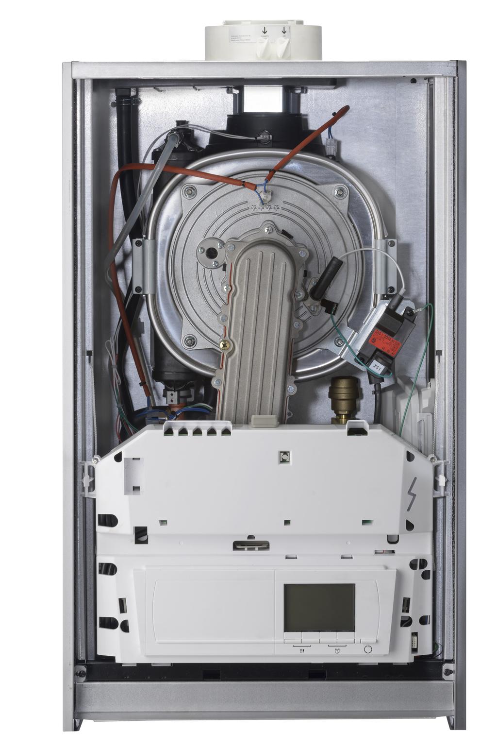
91
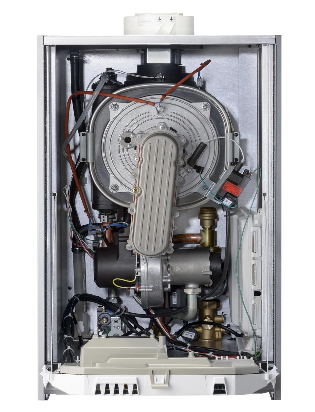
92


93 ELECTRICAL TERMINAL STRIP LOCATIONS Thermostat T-T (OT), Outdoor Sensor, DHW Sensor and optional LWCO terminal block are located in Main Control Box. Fold down control box and lift rear cover to access. LOW VOLTAGE System Pump and 3-WV terminal block is located in Auxiliary Control Box. Remove one screw and box slides forward for easy access. HIGH VOLTAGE REV A [02/09/2017]
94 Multi-Zone Valve with Prioity DHW - Argo AZ-CP Zone Control - Argo AR822-II Boiler Jumper On T-T Tank Sensor Primary Secondary Connection Jumper on 3 & 4 Supply Return Priority Pump & Priority Both ON REV A [02/09/2017]
95 Multi-Zone Pumps with Prioity DHW - Argo ARM Zone Control - Argo AR822-II Boiler Jumper On T-T Tank Sensor Primary Secondary Connection Supply Return 120 VAC Priority Switch ON REV A [02/09/2017]
96 Multi-Boilers with Zone Pumps and Optional Indirect Tank Optional Indirect Tank If Using Optional Indirect Tank White/Blue Indirect Tank Pump Primary Loop or System Pump ECR P/N Yellow Orange White/Yellow See Installation, Operation and Maintenance Manual for AMB8 Control Setup POLARITY MUST BE OBSERVED OR DAMAGE TO BOILER CONTROLS WILL RESULT Low Voltage Terminal Block Located in Boiler Main Control Box High Voltage Terminal Block Located in Boiler Auxiliary Control Box REV A [02/09/2017]

97 HEAT EXCHANGER CLEANING KIT INSTRUCTIONS HEAT ONLY UCS/DMG 240 CONDENSING, GAS BOILER Kit installation shall be completed by qualified agency.! WARNING Fire, explosion, asphyxiation and electrical shock hazard. Improper installation could result in death or serious injury. Read this instruction and understand all requirements, including requirements of authority having jurisdiction, before beginning installation. Installation not complete until appliance operation verified per Installation, Operation & Maintenance Manual provided with boiler.! WARNING Combustion chamber insulation in this product contains ceramic fiber material. Ceramic fibers can be converted to cristobalite in very high temperature applications. The International Agency for Research on Cancer (IARC) has concluded, Crystalline silica inhaled in the form of quartz or cristobalite from occupational sources is carcinogenic to humans (Group1). Avoid breathing dust and contact with skin and eyes. Use NIOSH certified dust respirator (N95). This type of respirator is based on the OSHA requirements for cristobalite at the time this document was written. Other types of respirators may be needed depending on the job site conditions. Current NIOSH recommendations can be found on the NIOSH website at html. NIOSH approved respirators, manufacturers, and phone numbers are also listed on this website. Wear long-sleeved, loose fitting clothing, gloves, and eye protection. Apply enough water to the combustion chamber lining to prevent dust. Wash potentially contaminated clothes separately from other clothing. Rinse clothes washer thoroughly. Sight Glass HEAT EXCHANGER CLEANING KIT Includes: Description PART # Qty GLOVE, LATEX, LG - 4 SHIELD, HEAT EXCHANGER,TARGET WALL - 1 HX CHAMBER GASKET - 1 FIBERGLASS ROPE GASKET - 1 GASKET G3/4 17X24X2 (227 only) - 1 POLY BAGS - 4 BRUSH, 2"X3", WITH HANDLE 1" STIFF BRISTLE INSTRUCTIONS Figure 1 - Sight Glass & Heat Exchanger Cover Four (4) 10mm Nuts - 1 NIOSH stated First Aid. Eye: Flush immediately. Breathing: Fresh air.! CAUTION Laceration, burn hazard. Metal edges and parts may have sharp edges and/or may be hot. Use appropriate personal protection equipment to include safety glasses and gloves when installing or servicing this boiler. Failure to follow these instructions could result in minor or moderate injury. Igniter Rev. A [9//01/2018]


98 HEAT EXCHANGER CLEANING KIT INSTRUCTIONS 1. Follow instructions TO TURN OFF GAS TO APPLIANCE found on Operating Instructions label on boiler or in Installation, Operation & Maintenance Manual. Verify all electrical power to boiler is turned off. Figure 2 - Control Panel and Tab! WARNING Electrical shock hazard. Turn OFF electrical power supply at service panel. Tab 2. Turn power and gas off to the boiler. 3. Remove two (2) screws at bottom of front jacket cover. Lift jacket up and off. Control Panel! WARNING Burn hazard. Verify heat exchanger, igniter, and flame sensor have cooled or use appropriate personal protection equipment before removing. Figure 3 - Condensate Drain 4. Inspect combustion chamber through sight glass. Verify flame is not present. See Figure Allow Boiler to cool. 6. Disconnect condensate drain from bottom of boiler. Place a bucket to collect any soot or dirt and cleaning solution under condensate location. See Figure Disconnect nut attachment to venturi, fan assembly. After removing gas line connection, cover opening of gas line with piece of duct tape. Condensate Drain 8. Remove electrical connectors from fan assembly. See Figure Remove Igniter plugs. Remove igniter ground wire. See Figure Remove 4 nuts from heat exchanger door. Remove heat exchanger door, gasket, and blower assembly. Gently place assembly off to side. Figure 5. Figure 4 - Gas Line Nut Fan 11. Cover control panel and all other components below heat exchanger with plastic bags provided. 12. Inspect burner, electrode position and insulation, cleaning or replace if necessary. See Figure 6. Gas Line Nut Gas Line 13. Examine seals, insulation and gaskets, replace if necessary. Fan Harness 14. Place protector for target wall insulation securely at rear of heat exchanger compartment. 15. Vacuum all loose debris from heat exchanger compartment Rev. A [9//01/2018]


99 HEAT EXCHANGER CLEANING KIT INSTRUCTIONS Figure 5 - Combustion Chamber Cover Assembly 16. Brush heat exchanger with brush provided, vacuum again. Heat Exchanger Ground Wire Igniter 4 Nuts Securing Heat Exchanger Door Flame Sensor 17. Spray entire heat exchanger thoroughly with 50/50 mix of vinegar and water (field provided) let set for 10 minutes. 18. Brush and vacuum entire surface again. Repeat this step until you have used all 16 oz. in spray bottle. 19. Rinse entire heat exchanger with water thoroughly. 20. Assure condensate trap is not blocked. Disconnect condensate drain tubes from condensate trap. Remove screw securing trap to C-frame. Remove any deposits from trap. Clean as necessary. Reinstall trap with screw and reconnect 2 drain tubes. 21. Reconnect condensate drain to bottom of boiler and rinse heat exchanger surface again. Remove protector from target wall insulation in rear of heat exchanger chamber. Figure 6 - Burner Flame Sensor 22. Replace combustion chamber gasket with new gasket supplied in kit. 23. Place heat exchanger door back into place and tighten all 4 nuts back down. Proper bolt torque is 4 ft-lbs. See Figure 5 Door Insulation Burner 24. Remove duct tape from gas line. Reconnect nut securing gas line to venturui, fan assembly using new gasket provided. See Figure Re-connect ground, flame sensor and igniter cable. See Figure Re-connect wire harnesses to fan assembly. Spark Igniter 27. Remove plastic bags. Heat Exchanger Door Gasket 28. Place control in upward position. 29. Turn power and gas on. Check all operations of appliance. 30. Check for gas leakage at connection to fan assembly. 31. Perform combustion test as outlined in Installation, Operation & Maintenance Manual. 32. Resume operation using OPERATING INSTRUCTIONS found on Operating Instructions label on boiler or in Installation, Operation & Maintenance Manual. 33. Install front panel. Secure with two screws at bottom of front panel. 34. Verify proper operation Rev. A [9//01/2018]
CONDENSING GAS FIRED FLOOR OR WALL MOUNTED BOILER INSTALLATION, OPERATION & MAINTENANCE MANUAL Model DMG-380
 CONDENSING GAS FIRED FLOOR OR WALL MOUNTED BOILER INSTALLATION, OPERATION & MAINTENANCE MANUAL Model DMG-380 Manufactured by: ECR International Inc. 2201 Dwyer Avenue, Utica, NY 13501 Tel. 800 253 7900
CONDENSING GAS FIRED BOILER INSTALLATION, OPERATION & MAINTENANCE MANUAL
 Models DMG-240 CONDENSING GAS FIRED BOILER INSTALLATION, OPERATION & MAINTENANCE MANUAL Manufactured by: ECR International Inc. 2201 Dwyer Avenue, Utica, NY 13501 Tel. 800 253 7900 www.ecrinternational.com
Models UBSSC-050 UBSSC-075 UBSSC-100 UBSSC-150 UBSSC-200 UBSSC-299 WALL MOUNTED GAS BOILER INSTALLATION, OPERATION & MAINTENANCE MANUAL
 Models UBSSC-050 UBSSC-075 UBSSC-100 UBSSC-150 UBSSC-200 UBSSC-299 WALL MOUNTED GAS BOILER INSTALLATION, OPERATION & MAINTENANCE MANUAL 050/075/100 SIZE SHOWN Manufactured by: ECR International, Inc. 2201
WALL MOUNTED GAS BOILER. INSTALLATION, OPERATION & MAINTENANCE MANUAL Models SSV-050 SSV-075 SSV-100 SSV-150 SSV-200
 WALL MOUNTED GAS BOILER INSTALLATION, OPERATION & MAINTENANCE MANUAL Models SSV-050 SSV-075 SSV-100 SSV-150 SSV-200 Manufactured by: ECR International, Inc. 2201 Dwyer Avenue, Utica NY 13501 web site:
INSTALLATION INSTRUCTIONS
 PRODUCT LITERATURE Lennox Industries Inc. Dallas, Texas INSTALLATION INSTRUCTIONS GWM-050IE, GWM-075IE, GWM-100IE, GWM-150IE, GWM-200IE, WALL MOUNTED GAS BOILER RETAIN THESE INSTRUCTIONS FOR FUTURE REFERENCE
Vent Supplement Ultra-80, -105, -155, -230 & -310
 Gas-fired water boiler Vent Supplement Ultra-80, -105, -155, -230 & -310 Installation of: Vent piping Air piping with This document must only be used by a qualified heating installer/service technician.
Models CHB/CCB APPLICATION GUIDE WALL MOUNTED GAS BOILER
 Models CHB/CCB APPLICATION GUIDE WALL MOUNTED GAS BOILER This manual has been prepared for use with the appropriate Installation, Operation and Maintenance Manual. For use with CCB/CHB Boilers ONLY. Manufactured
INSTALLATION INSTRUCTIONS
 PRODUCT LITERATURE Lennox Industries Inc. Dallas, Texas INSTALLATION INSTRUCTIONS GWM-050IE, GWM-075IE, GWM-100IE, GWM-150IE, GWM-200IE WALL MOUNTED GAS BOILER RETAIN THESE INSTRUCTIONS FOR FUTURE REFERENCE
WALL MOUNTED STAINLESS STEEL CONDENSING GAS BOILER
 WALL MOUNTED STAINLESS STEEL CONDENSING GAS BOILER INSTALLATION, OPERATION AND MAINTENANCE MANUAL MODELS BWMAAN000050 BWMAAN000075 BWMAAN000100 BWMAAN000150 BWMAAN000200 CAC/BDP 7310 West Morris St. Indianapolis,
PVC, CPVC, PP & SS Vent Supplement
 PVC, CPVC, PP & SS Vent Supplement L I S T E D This document is intended to be used by a qualified heating contractor or service technician. Read all instructions within this document and within the PRESTIGE
USER'S INFORMATION MANUAL
 USER'S INFORMATION MANUAL WARNING: If the information in this manual is not followed exactly, a fire or explosion may result causing property damage, personal injury or loss of life. Do not store or use
INSTALLATION AND SERVICE MANUAL
 INSTALLATION AND SERVICE MANUAL HORIZONTAL COMBUSTION AIR INLET KITS CATEGORY III VENTING FOR SEPARATED COMBUSTION TUBULAR GAS FIRED UNIT HEATERS USE 5 INCH KIT FOR UNITS WITH CAPACITIES 100,000 TO 250,000
ASX7-4-IOM-6 J
 INSTALLATION INSTRUCTIONS 4" COMBUSTION AIR INLET KIT TUBULAR GAS FIRED DIRECT SPARK PROPELLER UNIT HEATERS UNIT CONVERSION & CATEGORY III VENTING FOR SEPARATED COMBUSTION For 30,000 to 75,000 BTU/HR SUPPLEMENT
UTICA BOILER. SSV Submittal. Project Name: Project Location: Contractor:
 UTICA BOILER SSV - 399 Submittal Engineer: Project Name: Project Location: Contractor: APPLICATION: Gas fired hot water heating boiler for indoor installations. Approved for closet or alcove installations.
USER'S INFORMATION MANUAL
 USER'S INFORMATION MANUAL WARNING: If the information in this manual is not followed exactly, a fire or explosion may result causing property damage, personal injury or loss of life. Do not store or use
ASX7-5-IOM-3 J
 INSTALLATION INSTRUCTIONS 5" CONCENTRIC VENT TERMINAL KIT TUBULAR GAS FIRED DIRECT SPARK PROPELLER UNIT HEATERS UNIT CONVERSION & CATEGORY III VENTING FOR SEPARATED COMBUSTION For 90,000 to 120,000 BTU/HR
Direct Exhaust Venting Kit Instructions
 CONDENSING GAS BOILER 220/299/300/399 Direct Exhaust Venting Kit Instructions Evergreen 220/299/300/399 Kit part number 383-500-769 STOP! Read before proceeding Hazard definitions The following defined
USER'S INFORMATION MANUAL
 USER'S INFORMATION MANUAL : If the information in this manual is not followed exactly, a fire or explosion may result causing property damage, personal injury or loss of life. Do not store or use gasoline
AFUE 95% Heating Input 50,000 to 200,000 Btuh
 PRODUCT SPECIFICATIONS WATER HEATERS / BOILERS GWM-IE Gas-Fired, Modulating, Condensing, Wall Hung Hot Water Boiler Bulletin No. 210650 March 2018 Supersedes December 2015 AFUE 95% Heating Input 50,000
INSTALLATION AND SERVICE MANUAL
 INSTALLATION AND SERVICE MANUAL VERTICAL COMBUSTION AIR INLET KITS CATEGORY III VENTING FOR SEPARATED COMBUSTION TUBULAR GAS FIRED UNIT HEATERS USE 5 INCH KIT FOR UNITS WITH CAPACITIES 100,000 TO 250,000
USER'S INFORMATION MANUAL
 USER'S INFORMATION MANUAL WARNING: If the information in this manual is not followed exactly, a fire or explosion may result causing property damage, personal injury or loss of life. Do not store or use
Mod Con INSTALLATION START-UP MAINTENANCE PARTS. Mod Con Models 300 / 500 / 850 LP / HL / LPHL
 Mod Con INSTALLATION START-UP MAINTENANCE PARTS Mod Con Models 300 / 500 / 850 LP / HL / LPHL This manual must only be used by a qualified heating installer/service technician. Read all instructions in
USER'S INFORMATION MANUAL
 USER'S INFORMATION MANUAL WARNING: If the information in this manual is not followed exactly, a fire or explosion may result causing property damage, personal injury or loss of life. Do not store or use
Q SERIES II GAS-FIRED, DIRECT VENT, CONDENSING, HOT WATER BOILER
 Models OQ90-125 OQ90-150 OQ90-175 OQ90-200 Q90 125-200 SERIES II GAS-FIRED, DIRECT VENT, CONDENSING, HOT WATER BOILER INSTALLATION, OPERATION & MAINTENANCE MANUAL An ISO 9001-2008 Certified Company 2201
USER'S INFORMATION MANUAL
 USER'S INFORMATION MANUAL WARNING: If the information in this manual is not followed exactly, a fire or explosion may result causing property damage, personal injury or loss of life. Do not store or use
GWS. Venting Manual. Gas-Fired Water Boilers. Hazard definitions. Contents. Venting method definitions
 GWS Gas-Fired Water Boilers Venting Manual Hazard definitions Contents Page Hazards that will cause severe personal injury, death or substantial property damage. Hazards that can cause severe personal
Universal Fire Tube Boiler Wall Mount Models
 Universal Fire Tube Boiler Wall Mount Models USER S INFORMATION MANUAL Models WBRU**80W / 100W / 120W / 140W / 175W / 199W **NG denotes Natural Gas Model, LP Denotes Propane Model Heat Exchanger Bears
INSTALLATION AND OPERATING INSTRUCTIONS TABLE OF CONTENTS IMPORTANT
 C US This manual must be left with owner and should be hung on or adjacent to the boilerfor reference. COMMON VENTING MODELS CHS-300 through CHS-399 INSTALLATION AND OPERATING INSTRUCTIONS TABLE OF CONTENTS
VSL II QUICK START GUIDE
 This Quick Start Guide must be left with owner and should be hung on or adjacent to the boiler for reference. VSL II QUICK START GUIDE DIRECT-VENT SEALED COMBUSTION CONDENSING BOILER ~ GAS-FIRED BOILER
Installation & Operation Manual Models:
 SJS-I-O Rev C Installation & Operation Manual Models: 60-119 : If the information in this manual is not followed exactly, a fire or explosion may result causing property damage, personal injury or loss
SAFETY INFORMATION SAFETY WARNINGS
 SAFETY INFORMATION SAFETY WARNINGS 2 USING THIS MANUAL USING THIS MANUAL n WARNING If the information in this manual is not followed exactly, a fire or explosion may result causing property damage, personal
GAS-FIRED, DIRECT VENT, CONDENSING, HOT WATER BOILER. Models (Series B) BW9AAN BW9AAN BW9AAN000100
 BW9AAN BW9AAN BW9AAN000100") GAS-FIRED, DIRECT VENT, CONDENSING, HOT WATER BOILER INSTALLATION, OPERATION AND MAINTENANCE MANUAL Models (Series B) BW9AAN000050 BW9AAN000075 BW9AAN000100 CAC/BDP 7310 West Morris St. Indianapolis, IN.
GAS-FIRED, DIRECT VENT, CONDENSING, HOT WATER BOILER INSTALLATION, OPERATION AND MAINTENANCE MANUAL Models (Series B) BW9AAN000050 BW9AAN000075 BW9AAN000100 CAC/BDP 7310 West Morris St. Indianapolis, IN.
EUTECTIC EC-10DV Series
 EUTECTIC EC-10DV Series DIRECT VENT OIL-FIRED WATER BOILER/NO. 2 OIL VENTING INSTALLATION INSTRUCTIONS CONTENTS..........................................PAGE Basic Guidelines..........................................1
User s Information Manual
 User s Information Manual Gas-Fired Water Boilers With or without Aqua Logic (CWH) Now available Matching High Performance Companion Water Heater (Unit sold separately) If the information in this manual
Q95M-200 GAS-FIRED DIRECT VENT MODULATING HOT WATER BOILER. Model INSTALLATION, OPERATION & MAINTENANCE MANUAL Q95M-200
 Model Q95M-200 Q95M-200 GAS-FIRED DIRECT VENT MODULATING HOT WATER BOILER INSTALLATION, OPERATION & MAINTENANCE MANUAL An ISO 9001-2008 Certified Company 2201 Dwyer Avenue, Utica NY 13501 web site: www.ecrinternational.com
POWER VENTER. Model: PVE Series
 POWER VENTER Model: PVE Series CONTENTS Typical Venting System Components... System Operation... Power Venter Sizing... Installation Safety Instructions... Installation of Power Venter... Connecting Power
UB Series 2 GAS-FIRED, DIRECT VENT, CONDENSING, HOT WATER BOILER. Models UB90-50 UB90-75 UB INSTALLATION, OPERATION & MAINTENANCE MANUAL
 UB90-100 Series 2 Models UB90-50 UB90-75 UB90-100 GAS-FIRED, DIRECT VENT, CONDENSING, HOT WATER BOILER INSTALLATION, OPERATION & MAINTENANCE MANUAL An ISO 9001-2008 Certified Company 2201 Dwyer Avenue,
Installation and Operation Instructions Manual
 To the Installer: Please attach these instructions next to the water heater. To the Consumer: Please read these and all component instructions and keep for future reference. Installation and Operation
Q SERIES II GAS-FIRED DIRECT VENT CONDENSING HOT WATER BOILER
 Models Q90-125 Q90-150 Q90-175 Q90-200 Q90 125-200 SERIES II GAS-FIRED DIRECT VENT CONDENSING HOT WATER BOILER INSTALLATION, OPERATION & MAINTENANCE MANUAL An ISO 9001-2008 Certified Company 2201 Dwyer
Gas Fired Residential Combi Boiler Floor and Wall Mount Models
 Gas Fired Residential Combi Boiler Floor and Wall Mount Models USER S INFORMATION MANUAL Models WBRC**140W WBRC**199W WBRC**140F WBRC**199F ** NG Refers to Natural Gas Operation LP Refers to Propane Gas
INSTALLATION INSTRUCTIONS
 INSTALLATION INSTRUCTIONS G1D91BT, CG90TB, & G1D93BT High Efficiency 90+ Condensing Gas Furnace WARNING Improper installation, adjustment, alteration, service, or maintenance can cause injury or property
Esteem 399 Low NOx Gas Fired Boiler
 Instruction No. AERCO INTERNATIONAL, Inc. Northvale, New Jersey, 07647 USA PVC & CPVC Vent Installation Supplement Esteem 399 Low NOx Gas Fired Boiler I S T E D L Visit www.aerco.com to View the Latest
H 2. Hot Water Storage/ Booster Tanks. For Single Tank Installations INSTALLATION, OPERATION & MAINTENANCE MANUAL
 H 2 O Hot Water Storage/ Booster Tanks For Single Tank Installations INSTALLATION, OPERATION & MAINTENANCE MANUAL 30, 40, 60, 80, 115 Gallon L = Low Boy Profile C = Commercial Pipe Connections Conforms
ProLine XE Combi Boiler
 100298581_2000552611_Rev A ProLine XE ProLine XE User Manual Models: 110-150 - 199 If the information in this manual is not followed exactly, a fire or explosion may result causing property damage, personal
GOLD Plus 30/40/60/80
 PLUS Line Indirect-Fired Water Heaters Series 3 Manual Installation Startup Maintenance Parts PLUS 100/110/119 GOLD Plus 30/40/60/80 Plus 40/60/80 This manual must only be used by a qualified heating installer/service
User s Information Manual Models:
 FB-USER Rev C User s Information Manual Models:1.5-5.0 WARNING: If the information in these instructions is not followed exactly, a fire or explosion may result causing property damage, personal injury
Project Name: Location: Engineer: Contractor: I. GENERAL
 Part I - General Part II - Product Part III - Installation Project Name: Location: Engineer: Contractor: I. GENERAL I. PRODUCT Rep: Date: A. Supply and install modulating and condensing boiler(s) as specified
POWER VENTER SYSTEM. Model: PVO-300, PVO-600
 POWER VENTER SYSTEM Model: PVO-300, PVO-600 Included is one ETL and cetl listed Power Venter to be used primarily with a single 120VAC controlled oil fired furnace, boiler, or water heater. The PVO may
Installation & Operation Manual Models: TSU
 TSU-I-O Rev A Installation & Operation Manual Models: TSU 150-940 CAUTION: This appliance is not intended for potable water. This manual must only be used by a qualified heating installer / service technician.
OPERATING INSTRUCTIONS MANUAL (Please retain for future reference) FVN/P-400 INDIRECT FIRED SPACE HEATERS
 FVN/P-400 INDIRECT FIRED SPACE HEATERS") OPERATING INSTRUCTIONS MANUAL (Please retain for future reference) For FVN/P-400 INDIRECT FIRED SPACE HEATERS CERTIFIED FOR USE IN CANADA AND U.S.A. As per Standard ANSI Z83.7/CSA 21.4 2000 Gas Fired Construction
OPERATING INSTRUCTIONS MANUAL (Please retain for future reference) For FVN/P-400 INDIRECT FIRED SPACE HEATERS CERTIFIED FOR USE IN CANADA AND U.S.A. As per Standard ANSI Z83.7/CSA 21.4 2000 Gas Fired Construction
Installing, Operating & Maintaining MUNCHKIN HIGH EFFICIENCY HEATER with the 925 Controller
 Installing, Operating & Maintaining MUNCHKIN HIGH EFFICIENCY HEATER with the 925 Controller WARNING If the information in this manual is not followed exactly, a fire or explosion may result causing property
VSL II QUICK START GUIDE
 This Quick Start Guide must be left with owner and should be hung on or adjacent to the boiler for reference. VSL II QUICK START GUIDE DIRECT-VENT SEALED COMBUSTION CONDENSING BOILER ~ GAS-FIRED BOILER
Common Vent System. Common Vent System
 Common Vent System Common Vent System Installation Manual Independently tested and approved by CSA Keep this manual for future reference whenever maintenance or service is required. WARNING If the information
PVE SERIES POWER VENTER SYSTEM MANUAL
 PVE SERIES POWER VENTER SYSTEM MANUAL Contents Page I. Typical Venting System Components 2 II. System Operation 3 III. Power Venter Sizing 3,4 IV. Installation Safety Instructions 5,6 V. Installation of
Installation Instructions T 9822 Gas Dryer. en - US, CA. To prevent accidents
 Installation Instructions T 9822 Gas Dryer To prevent accidents en - US, CA and appliance damage read these instructions before installation or use. M.-Nr. 07 431 110 2 WARNING For your safety the information
OPERATING INSTRUCTIONS MANUAL (Please retain for future reference) FVN/P-400 INDIRECT FIRED SPACE HEATERS
 FVN/P-400 INDIRECT FIRED SPACE HEATERS") OPERATING INSTRUCTIONS MANUAL (Please retain for future reference) For FVN/P-400 INDIRECT FIRED SPACE HEATERS CERTIFIED FOR USE IN CANADA AND U.S.A. As per Standard ANSI Z83.7/CSA 21.4 2000 Gas Fired Construction
OPERATING INSTRUCTIONS MANUAL (Please retain for future reference) For FVN/P-400 INDIRECT FIRED SPACE HEATERS CERTIFIED FOR USE IN CANADA AND U.S.A. As per Standard ANSI Z83.7/CSA 21.4 2000 Gas Fired Construction
High Effi ciency Condensing Stainless Steel Gas Hot Water Supply Boiler Models IEW-199, IEW-399 Installation and operation instructions
 IE8000-R1 High Efficiency Condensing Stainless Steel Gas Hot Water Supply Boiler Models IEW-199, IEW-399 Boiler manual Installation and operation instructions CONTROLS 260 North Elm Street 7555 Tranmere
MODELS LFP4218/LFP6018 TOP VENT GAS FIREPLACE
 MODELS LFP4218/LFP6018 TOP VENT GAS FIREPLACE PFS APPROVED FOR NATURAL GAS OR PROPANE GAS Z21.50-2014 If your plans do not allow for the venting system as outlined previously in the installing chimney/vent
INSTALLATION INSTRUCTIONS
 INSTALLATION INSTRUCTIONS HORIZONTAL COMBUSTION AIR INLET KITS CATEGORY III VENTING FOR SEPARATED COMBUSTION TUBULAR GAS FIRED DUCT FURNACES USE 5 KIT FOR UNITS WITH CAPACITIES 100,000 TO 200,000 BTU/HR
Installing, Operating & Maintaining MUNCHKIN VWH HIGH EFFICIENCY HOT WATER SUPPLY BOILER
 Installing, Operating & Maintaining MUNCHKIN VWH HIGH EFFICIENCY HOT WATER SUPPLY BOILER WARNING If the information in this manual is not followed exactly, a fire or explosion may result causing property
TRIAD Boiler Systems, Inc Atlantic Drive, Unit 2 West Chicago, IL
 TRIIUMPH SERIIES AIIR SUPPLY AND VENTIING GUIIDE C.S.A Design-Certified Complies with ANSI Z21.13/CSA 4.9 Gas-Fired Low Pressure Steam & Hot Water Boilers ASME Code Section IV C.S.A Design-Certified Complies
Aqua Balance. User s Information Manual. WMB-155C Wall Mount Gas-Fired Combination Boiler Heating and Domestic Hot Water
 Aqua Balance WMB-155C Wall Mount Gas-Fired Combination Boiler Heating and Domestic Hot Water User s Information Manual * Low Lead Content If the information in this manual is not followed exactly, a fire
MC Series Gas-Fired Circulating Heater
 MC Series Gas-Fired Circulating Heater INSTALLATION START-UP MAINTENANCE PARTS Models MC50 / MC80 MC99 / MC120 When installing models manufactured after July 7, 2008, you will notice additional selections
SVB SERIES II. Gas-Fired Hot Water Induced Draft Boilers. Models SVB-2 SVB-3 SVB-4 SVB-5 SVB-6 SVB-7 INSTALLATION, OPERATION & MAINTENANCE MANUAL
 SVB SERIES II Gas-Fired Hot Water Induced Draft Boilers Models SVB-2 SVB-3 SVB-4 SVB-5 SVB-6 SVB-7 INSTALLATION, OPERATION & MAINTENANCE MANUAL C.S.A. Certified For Natural Gas Or Propane Tested For 50
LGB Gas fired boiler
 LGB Gas fired boiler Control Supplement LGB-5 Series 2 Propane gas CSD-1 Control System Part Number 550-110-682/0304 Please read this page first Hazard definitions To the installer... The following terms
Installing, Operating & Maintaining MUNCHKIN HIGH EFFICIENCY HEATER with the 925 Controller
 Installing, Operating & Maintaining MUNCHKIN HIGH EFFICIENCY HEATER with the 925 Controller WARNING If the information in this manual is not followed exactly, a fire or explosion may result causing property
Installation and Operation Instructions Manual
 To the Installer: Please attach these instructions next to the water heater. To the Consumer: Please read these and all component instructions and keep for future reference. Installation and Operation
User s Information Manual
 User s Information Manual Gas-Fired Storage Water Heater, Tankless Water Heater, Heating Appliance, and Combination Appliance Models IF THE INFORMATION IN THIS MANUAL IS NOT FOLLOWED EXACTLY, A FIRE OR
Residential Gas Hybrid Water Heater
 Residential Gas Hybrid Water Heater USER S INFORMATION MANUAL WGRGH20NG75F / WGRGH20NG76F / WGRGH20NG100F WGRGHNG75F / WGRGHNG76F / WGRGHNG100F Models* *A suffix of LP denotes propane gas NOTICE: Westinghouse
THIS MANUAL IS FOR USE WITH REV. 3 MOD CON BOILERS MANUFACTURED AFTER DECEMBER 1, 2012
 Mod Con INSTALLATION START-UP MAINTENANCE PARTS Models 500 / 850 LP / HL / LPHL THIS MANUAL IS FOR USE WITH REV. 3 MOD CON BOILERS MANUFACTURED AFTER DECEMBER 1, 2012 Heat Exchanger Bears the ASME H Stamp
Manual Addendum. This Addendum needs to be used in conjunction with the Evergreen Boiler Manual P/N _0518
 Manual Addendum This Addendum needs to be used in conjunction with the Evergreen Boiler Manual P/N 550-100-191_0518 ATTENTION to installers and homeowners of Evergreen boilers. KEEP THIS ADDENDUM WITH
Installation Instructions
 Installation Instructions Vent/Exhaust Pipe External Trap Kit KGAET0101ETK Table 1 Kit Contents PART DESCRIPTION PART NO. QUANTITY Condensate Trap 308589-402 1 Tee-Vent Fitting (2-in. PVC) 321496-301 1
C1210ES Tankless Water Heater
 Engineering Submittal Sheet Dimensions and Connections B C D C Combustion air inlet Exhaust outlet Optional combustion air inlet Top view Top view A E Hot water outlet Cold water inlet F H J C I K G Front
Installing, Operating & Maintaining MUNCHKIN HIGH EFFICIENCY 399M COMMERCIAL BOILER
 Installing, Operating & Maintaining MUNCHKIN HIGH EFFICIENCY 399M COMMERCIAL BOILER WARNING If the information in this manual is not followed exactly, a fire or explosion may result causing property damage,
Aqua Balance. Direct Exhaust Venting Kit Instructions
 Aqua Balance WMB-155H and WMB-155C Wall Mount Gas-Fired Heating Only Boiler & Combination Boiler Heating and Domestic Hot Water Direct Exhaust Venting Kit Instructions AquaBalance TM WMB-155H & WMB-155C
Do not use this vent pipe or fittings for venting incinerators of any kind.
 ! CAUTION! Do not use this vent pipe or fittings for venting incinerators of any kind. C.S.A. Certified For Natural Gas Or Propane Tested For 100 LBS. ASME Working Pressure For correct installation of
XEB Series II. Models XEB-2 XEB-3 XEB-4 XEB-5 XEB-6 XEB-7. Gas-Fired Hot Water Induced Draft Boilers INSTALLATION, OPERATION & MAINTENANCE MANUAL
 Models XEB-2 XEB-3 XEB-4 XEB-5 XEB-6 XEB-7 XEB Series II Gas-Fired Hot Water Induced Draft Boilers INSTALLATION, OPERATION & MAINTENANCE MANUAL C.S.A. Certified For Natural Gas Or Propane Tested For 50
C1050ES Tankless Water Heater
 Engineering Submittal Sheet Dimensions and Connections B C D C Combustion air inlet Exhaust outlet Optional combustion air inlet Top view Top view A E F Hot water outlet Cold water inlet Inlet water filter
RTG 199 HE INDOOR MODEL. RTG 199 HEN - Natural Gas RTG 199 HEX - Propane (LP Gas) Installation and Operation instructions
 Installation and Operation instructions") Installation and Operation instructions INDOOR MODEL RTG 199 HE Warning: If the information in this manual is not followed exactly, a fire or explosion may result causing property damage, personal injury
Installation and Operation instructions INDOOR MODEL RTG 199 HE Warning: If the information in this manual is not followed exactly, a fire or explosion may result causing property damage, personal injury
Trinity Lx400 High Efficiency Gas Condensing Boiler & Water Heater
 Part I - General Part II - Product Part III - Installation Project Name: Location: Engineer: Contractor: I. GENERAL Rep: Date: A. Supply and install modulating and condensing boiler(s)/water heater(s)
Bosch Greentherm T9800 SE 199 Gas Tankless Water Heater
 Engineering Submittal Sheet Product Overview & Certifications Engineering Specifications The system shall consist of gas tankless water heater model Greentherm T9800 SE 199 as manufactured by Bosch Thermotechnology.
INSTALLATION INSTRUCTIONS
 INSTALLATION INSTRUCTIONS VERTICAL COMBUSTION AIR INLET KITS CATEGORY III VENTING FOR SEPARATED COMBUSTION TUBULAR GAS FIRED DUCT FURNACES USE 5" KIT FOR UNITS WITH CAPACITIES 100,000 TO 200,000 BTU/HR
INSTALLATION INSTRUCTIONS G2D93CT, G2D93CU, G2D95CT, & G2D95CU High Efficiency Multiposition Gas Furnace with System Sentry Control System WARNING
 INSTALLATION INSTRUCTIONS G2D93CT, G2D93CU, G2D95CT, & G2D95CU High Efficiency Multiposition Gas Furnace with System Sentry Control System Save these instructions for future reference WARNING Improper
Low Water Cutoff (LWCO) IQ Option Card p/n , for Hot Water Boilers
 IQ Option Card p/n , for Hot Water Boilers") Low Water Cutoff (LWCO) IQ Option Card p/n 102711-01, 102714-01 for Hot Water Boilers Instruction Sheet 102-360 APPLICATION The Low Water Cutoff (LWCO) IQ Option Cards are advanced, microprocessor based
Low Water Cutoff (LWCO) IQ Option Card p/n 102711-01, 102714-01 for Hot Water Boilers Instruction Sheet 102-360 APPLICATION The Low Water Cutoff (LWCO) IQ Option Cards are advanced, microprocessor based
Installing, Operating & Maintaining MUNCHKIN HIGH EFFICIENCY HEATER with the 925 Controller
 Installing, Operating & Maintaining MUNCHKIN HIGH EFFICIENCY HEATER with the 925 Controller WARNING If the information in this manual is not followed exactly, a fire or explosion may result causing property
HIGH-EFFICIENCY DOWNFLOW / HORIZONTAL FURNACE INSTALLER'S INFORMATION MANUAL
 HIGH-EFFICIENCY DOWNFLOW / HORIZONTAL FURNACE INSTALLER'S INFORMATION MANUAL DESI GN C E R TI F I ED DOWNFLOW POSITION SHOWN ATTENTION, INSTALLER! After installing the furnace, show the user how to turn
Pellet Vent INSTALLATION INSTRUCTIONS
 Pellet Vent INSTALLATION INSTRUCTIONS A MAJOR CAUSE OF CHIMNEY RELATED FIRES IS FAILURE TO MAINTAIN REQUIRED CLEARANCES (AIR SPACES) TO COMBUSTIBLE MATERIALS. IT IS OF THE UTMOST IMPORTANCE THAT THIS PELLET
OPERATING INSTRUCTIONS MANUAL (Please retain for future reference) FVN/P-400 INDIRECT FIRED SPACE HEATERS
 FVN/P-400 INDIRECT FIRED SPACE HEATERS") OPERATING INSTRUCTIONS MANUAL (Please retain for future reference) For FVN/P-400 INDIRECT FIRED SPACE HEATERS CERTIFIED FOR USE IN CANADA AND U.S.A. As per Standard ANSI Z83.7/CSA 21.4 2000 Gas Fired Construction
OPERATING INSTRUCTIONS MANUAL (Please retain for future reference) For FVN/P-400 INDIRECT FIRED SPACE HEATERS CERTIFIED FOR USE IN CANADA AND U.S.A. As per Standard ANSI Z83.7/CSA 21.4 2000 Gas Fired Construction
Trinity Lx200 High Efficiency Gas Condensing Boiler & Water Heater
 Part I - General Part II - Product Part III - Installation Project Name: Location: Engineer: Contractor: I. GENERAL Rep: Date: A. Supply and install modulating and condensing boiler(s)/water heater(s)
Boiler Manual. Gas-fired water boilers. Featuring. Flexibility
 Gas-fired water boilers Featuring Flexibility Boiler Manual This manual must only be used by a qualified heating installer/service technician. Read all instructions, including this manual and all other
HIGH-EFFICIENCY UPFLOW FURNACE INSTALLER'S INFORMATION MANUAL
 HIGH-EFFICIENCY UPFLOW FURNACE INSTALLER'S INFORMATION MANUAL Model Numbers WMVSA054NH3R WMVSA072NH3R, WMVSA072NH4R WMVSA090NH3R, WMVSA090NH4R WMVSA108NH5R DESIGN WMVSA126NH5R C E R TI F I ED ATTENTION,
On-Demand Water Heater Installation Manual and Owner s Guide
 On-Demand Water Heater Installation Manual and Owner s Guide ANSI Z21.10.3 CSA 4.3 R D R 510C model only Models 110C 310C 510C WARNING If the information in these instructions is not followed exactly,
Installation guide and material checklists
 Featuring Flexibility Installation guide and material checklists Series 3 This guide must only be used by a quali!ed heating installer/service technician. Read all instructions, including the boiler manual
Installation. Manual. Installation. Startup Maintenance Parts WARNING
 Installation Manual Installation Startup Maintenance Parts MH18082 WARNING This manual must only be used by a qualified heating installer/service technician. Read all instructions in this manual before
Trinity Tft High Efficiency Gas Condensing Boiler & Water Heater
 Part I - General Part II - Product Part III - Installation Project Name: Location: Engineer: Contractor: I. GENERAL Rep: A. Supply and install modulating and condensing boiler(s) as specified herein. Date:
National Comfort Products 539 Dunksferry Road Bensalem, PA (215) Fax: (215)
 Fax: (215)") National Comfort Products 539 Dunksferry Road Bensalem, PA 19020 (215) 244-1400 1-800-523-7138 Fax: (215) 639-1674 14299575-10/29/2014 NOTE: These installation and maintenance instructions should be left
National Comfort Products 539 Dunksferry Road Bensalem, PA 19020 (215) 244-1400 1-800-523-7138 Fax: (215) 639-1674 14299575-10/29/2014 NOTE: These installation and maintenance instructions should be left
Utica Boilers MAC Submittal
 Utica Boilers MAC-150 - Submittal Engineer: Project Name: Project Location: Contractor: APPLICATION: Modulating Gas fired Combi boiler for indoor installation. Approved for closet or alcove installations.
VENTING CLEARANCES. BBT NORTH AMERICA Bosch Group. Bosch Water Heating 340 Mad River Park, Waitsfield, VT TWH-V-26 page 1 of 6 rev 01/06
 page 1 of 6 VENTING CLEARANCES The vents should not be obstructed and all joints properly fitted. Floors, ceilings and walls must be cut or framed to provide necessary clearance to vents. Metal strippings
Tankless Water Heater
 Tankless Water Heater USER S INFORMATION MANUAL Models WGRT**150 / WGRT**199 / WGRTC**199 **A suffix of LP denotes propane gas **A suffix of NG denotes natural gas NOTICE: Westinghouse reserves the right
CAUTION. Requests to Installers In order to use the water heater safely, read this installation manual carefully, and follow the installation
 Installation Manual NORITZ AMERICA CORPORATION CONDENSING TANKLESS GAS WATER HEATER NRC66-DV (Indoor Installation) Potential dangers from accidents during installation and use are divided into the following