Technical Development Program
|
|
|
- Frederick Blair
- 5 years ago
- Views:
Transcription


1 Technical Development Program PRESENTED BY: James Parker Insert your logo here AIR HANDLERS Coils: Direct Expansion Chilled Water and Heating
2 Menu Section 1 Introduction Section 2 Typical Coil Applications Section 3 Coil Terminology and Construction Section 4 Types of Coils Section 5 Heat Transfer and Coil Formulas Section 6 Application Topics Section 7 Cooling Coil Design Parameters Section 8 Coil Selections Section 9 Summary
3 SECTION 1 COILS: DIRECT EXPANSION, CHILLED WATER, AND HEATING Introduction Section 2 Duct Design Drivers
4 Objectives Identify where coils are used in HVAC Describe the various types of heating and cooling coils Define the component parts and terminology Identify the heat transfer formulas and properties Coil applications Describe methods to control water and direct expansion coils Identify coil selection criteria and factors affecting performance Section 1 Introduction


5 What is a Coil? A coil is a heat transfer device that adds or removes heat to the entering air Types of coils: Chilled Water Airflow Hot Water Direct Expansion (DX) Steam Electric Water Coil Return Header Supply Header Section 1 Introduction
6 SECTION 2 COILS: DIRECT EXPANSION, CHILLED WATER, AND HEATING Typical Coil Applications (Five General Categories)

7 Residential Coils Cased Uncased Section 2 Typical Coil Applications


8 Small Commercial Packaged Unit Coils Installed in duct A coil design, installed on twinned furnaces 6-10 Tons Section 2 Typical Coil Applications


9 Large Commercial Packaged Unit Coils DX or chilled water DX COOLING COIL IN ROOFTOP UNIT DX COOLING COIL IN PACKAGED AIR HANDLER Section 2 Typical Coil Applications
10 Duct Mounted Coils Drive Slip Casing Section 2 Typical Coil Applications
11 Duct Mounted Coil Ducting Flange Flanged Casing Ducting Section 2 Typical Coil Applications
12 Terminal Mounted Heating Coils Unit Mounted Hot Water Coil Fan Powered Box VAV Single Duct Box Section 2 Typical Coil Applications


13 Draw-Thru and Blow-Thru AHU Coil Coil Diffuser Plate Horizontal Draw-Thru Horizontal Blow-Thru Draw-Thru Fan downstream of cooling coil Fan draws air through coil Most common type Fan motor heat travels to conditioned space adding to the room BTUH load Advantages: Even airflow assured over the coil Shortest length required Coil Vertical Draw-Thru Blow-Thru Fan upstream of cooling coil Fan blows air through coil Diffuser plate needed which adds length Advantages: Motor heat becomes coil load NOT ROOM LOAD Less cfm required with smaller ducts and less fan energy Section 2 Typical Coil Applications
14 Coil Banks For applications requiring large volumes of air, one may opt for using multiple coils in a stacked configuration, instead of one very large coil. Arrangements can vary from just two coils stacked, to multiple banks four or more coils high. Note each coil requires its own drain pan, and there is a primary drain pan underneath the bottom coil. All the condensation from the upper coils is directed into the primary drain pan. Section 2 Typical Coil Applications
15 SECTION 3 COILS: DIRECT EXPANSION, CHILLED WATER, AND HEATING Coil Terminology and Construction
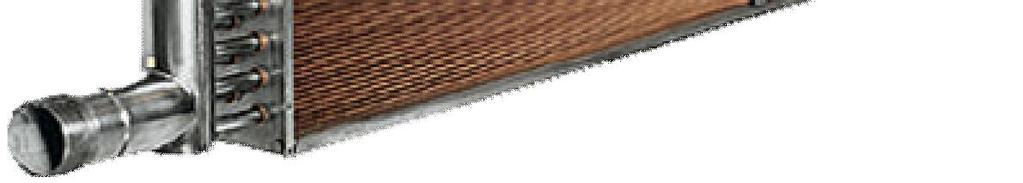
16 Coil Terminology Tubes Tubes The tube is a small-diameter conduit through which the heating or cooling medium passes as it rejects or absorbs heat Airflow Outlet 3/8, 1/2, and 5/8 inch Header Inlet Section 3 Coil Terminology and Construction


17 1/2-in. Tube vs. 5/8-in. Tube Coils You can achieve the same or lower pressure drop using a 1/2 in. coil with different circuiting. Section 3 Coil Terminology and Construction

18 1/2-in. Tube vs. 5/8-in. Tube Coils Section 3 Coil Terminology and Construction


19 Tube Wall Thickness Manufacturers may offer varying choices in tube wall thickness. One manufacturer s 1/2 tubes are.016 /.025, and the 5/8 tubes are.020 /.035 inches thick. Tube Wall Thickness Section 3 Coil Terminology and Construction


20 Fluid enters the coil counterflow to the air direction Coil Rows Airflow Rows Section 3 Coil Terminology and Construction


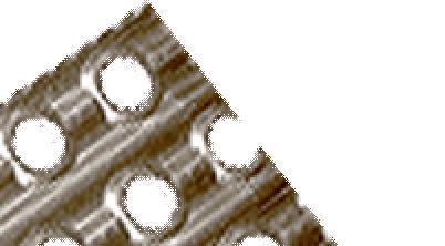
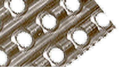
21 Rows and Fins Fin - The coil fin is a thin metal plate attached to the tube to improve the heat transfer efficiency from medium to air-stream Coil Fin Section 3 Coil Terminology and Construction

22 Coil Terminology H Finned or Face Area The working area of the coil is defined as the height length of the finned area. We need to know this in order to determine the face velocity across the coil. L This area does not include the extra dimensions for the casing. Face area or tube face area or finned area Section 3 Coil Terminology and Construction
23 Face Velocity Limitations (FPM) Face Area = Length * Height Length and height measured from inside edges of casing Length Height Face Velocity= CFM / FACE AREA Finned Area Section 3 Coil Terminology and Construction
24 Face Area Calculation The relationship between airflow volume (cfm), velocity (V) and area (A) is: cfm = VA or A = cfm/v Where: A = H * L H Example: 25,000 cfm AHU A = cfm / V A = 25,000 cfm / 500 fpm A = 50 ft 2 cooling coil required (nominal size 50 unit would be selected) L Section 3 Coil Terminology and Construction

25 Face Velocity Limits Section 3 Coil Terminology and Construction
26 Bypass Factor Causes ROWS BYPASS FACTOR AIR VELOCITY BYPASS FACTOR fpm 400 fpm 500 fpm 600 fpm FINS PER INCH BYPASS FACTOR AIR VELOCITY 300 fpm 400 fpm 500 fpm 600 fpm BYPASS FACTOR Section 3 Coil Terminology and Construction
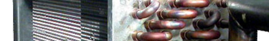
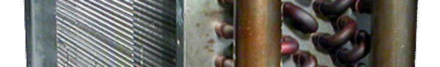
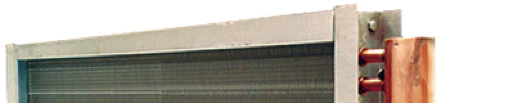
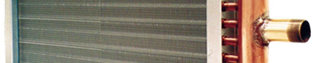
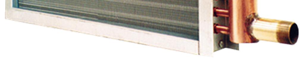
27 Header, Inlets and Outlets Header A large diameter pipe to which several tubes are connected Chilled Water Coil Inlet and Outlet Pipe stubs on the header where the heating or cooling medium enters and leaves the coil In steam coils, the inlet is always the higher stub, allowing condensation to drain out of the lower stub Section 3 Coil Terminology and Construction

28 Construction Materials Header Steel or Non-Ferrous (copper) Casing Galvanized or Stainless Steel. Drain Pan Condensate drain pans can be galvanized or stainless steel. Section 3 Coil Terminology and Construction


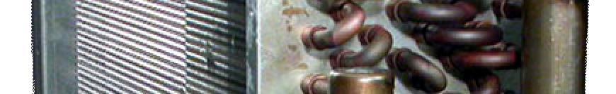
29 Refrigerant Distributors Suction Headers Refrigerant Distributors Feeder Tubes Tube Sheet Suction Connections Section 3 Coil Terminology and Construction
30 Chilled or Hot Water Coil Hand RH COIL LH COIL Section 3 Coil Terminology and Construction
31 Direct Expansion Coil Hand Suction Header LH COIL RH COIL Section 3 Coil Terminology and Construction
32 DX Coil Face Split Face Split Coils Split horizontally Subdivisions within the coil Parts of coil can be deactivated to alleviate low-load problems Face Split Allow more flexibility Can match with dual-circuit or multiple condensing units Section 3 Coil Terminology and Construction
33 DX Coil Row Split Row Split Coils (full face active) Intertwined Subdivisions within the coil Parts of coil can be deactivated to alleviate low-load problems Allow more flexibility Can match with dual-circuit or multiple condensing units Section 3 Coil Terminology and Construction

34 Vent And Drain Connections Vent and Drain Connections: Used on water coils Located on supply and return stubs Vents on top of coil allow purging of air from coil Periodic venting to maintain proper coil performance Air Vent Drains needed for: Freeze protection in cold climates Service drainage Section 3 Coil Terminology and Construction
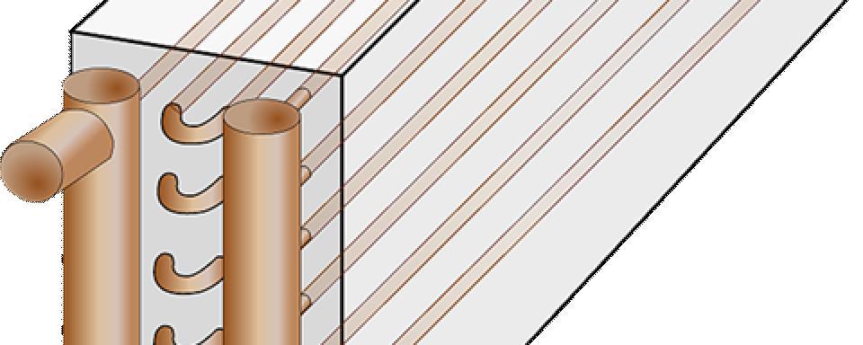
35 Return Bends, Hairpins, Passes Return Bends or Hairpins Hairpin OUTLET Header Airflow Tubes in Face = 6 Passes = 4 Rows = 4 INLET Feeder Tubes Section 3 Coil Terminology and Construction


36 Coil Circuiting Cooling or heating medium path of travel. Varies heat transfer performance Outlet Airflow Inlet Rows Section 3 Coil Terminology and Construction
37 Full Circuiting Airflow All of the tubes in face are fed from the header For 4-row coil shown: Circuits Passes = 4 Circuit length = One for each tube in face = 4 * coil length Rows Section 3 Coil Terminology and Construction
38 Half Circuiting Airflow Half of the tubes in face are fed from the header For 4-row coil shown: Circuits Passes = 8 Circuit length = ½ * of tubes in face = 8 * coil length Fluid velocity in tube: 2 * full circuit tube velocity Fluid pressure drop: ~ 4 * full circuit Rows Section 3 Coil Terminology and Construction
39 Quarter Circuiting Airflow ¼ of the tubes in face are fed from the header For 4-row coil shown: Circuits Passes = 16 Circuit length = ¼ * of tubes in face = 16 * coil length Fluid velocity in tube: 4 * full circuit tube velocity Fluid pressure drop: ~ 16 * full circuit Rows Section 3 Coil Terminology and Construction


40 Double Circuiting Airflow All tubes in face of two rows are fed from the header For 4-row coil shown: Circuits Passes = 2 Circuit length = 2 * of tubes in face = 2 * coil length Fluid velocity in tube: ½ * full circuit tube velocity Rows Fluid pressure drop: ~ ¼ * full circuit Section 3 Coil Terminology and Construction


41 More Than One Circuiting Can Work Airflow GPM: A < B Tube Velocity: A > B Airflow Pressure Drop: A > B More than one circuit will satisfy job Rows Rows Pick circuit that meets capacity, meets pressure drop limits, affords lowest cost, and gives good control range Section 3 Coil Terminology and Construction

42 Coil Circuiting Impact
43 Selection Options: (Highest to Lowest): Face area Rows Fins per inch Coil circuiting Coil Cost Factors Section 3 Coil Terminology and Construction
44 COILS: DIRECT EXPANSION, CHILLED WATER, AND HEATING Break
45 SECTION 4 COILS: DIRECT EXPANSION, CHILLED WATER, AND HEATING Types Of Coils


46 DX Coil Relationship To The System Exhaust Damper Return Air Fan Return Duct Supply Duct Return Damper HEAT Supply Air Fan Air Handler DX Coil Interconnecting Refrigerant Piping Air-Cooled Condensing Unit Section 4 Types of Coils


47 DX Coil Showing TXV Three limiting factors for capacity reduction: 1. Thermostatic Expansion Valve (TXV) 2. Distributor Nozzle 3. Evaporator Circuit Connects with TXV Feeler Bulb TXV Thermostat Expansion Valve Suction Header Distributor Assembly Airflow Liquid Line from Condenser To compressor suction TXV Feeler Bulb Distributor Nozzle Feeder Tube (one per refrigerant circuit) External Equalizer Line Section 4 Types of Coils
48 Evaporator Circuit Low Load Limit Refrigerant velocity in tubes must be maintained between prescribed minimum and maximum limits Maximum limits ensure reasonable pressure drop and efficient operation at design load Minimum limits ensure oil return to compressor at part load Low velocity may be caused by compressor unloading in response to load reduction The term tons per circuit is used to define velocity and represents how many tons of cooling are flowing through each circuit of the coil One manufacturer recommends 0.8 to 2.0 tons per circuit for ½ inch tube coils. Minimum s may vary by slightly by manufacturer. Section 4 Types of Coils

 with a 15-ton")
 Section 4")
49 Split Coil Control Example LIQUID LINE Filter Drier Capacity Control Solenoid TXV Distributor Sight Glass Application: Match coil at right (8 circuits) with a 15-ton condensing unit which has two steps of unloading: (100%, 67%, 33% ) Section 4 Types of Coils


50 Chilled Water Coil Relationship To The System Exhaust Damper Return Air Fan Return Duct Supply Duct Return Damper HEAT Coil Supply Air Fan Cooling Tower Air or Water-Cooled Chiller (shown) Section 4 Types of Coils


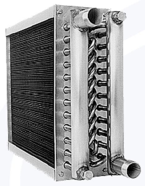
51 Typical Chilled Water Coil 4 to10 Rows Available Vent Copper Tubes Aluminum or Copper Fins Fin Spacing 8 to 14 fins/inch Water Outlet Cap unused water connections Non-ferrous or Steel Header Water Inlet Section 4 Types of Coils


52 Hot Water, Steam, Electric Heating Coils Hot Water Steam Electric Section 4 Types of Coils
53 Hot Water Coils Outlet Copper Tubes Aluminum or Copper Fins Hot Water Feeder Tubes Inlet Drain Section 4 Types of Coils


54 Inner Distributing Tube Steam Coil Inlet Outlet Copper Tubes Aluminum Fins Section 4 Types of Coils
55 SECTION 5 COILS: DIRECT EXPANSION, CHILLED WATER, AND HEATING Heat Transfer and Coil Formulas
56 Heat Given Up By Air Air Total Heat Transferred (Change in enthalpy): q t = 4.5 * cfm * (h e h l ) Sensible Heat Transferred (change in temperature): q s = 1.10 * cfm * (t e t l ) Latent Heat Transferred (Change in moisture): q l = 0.69 * cfm * (gr e gr l ) Section 5 Heat Transfer and Coil Formulas
 A = Total Coil Effective")

57 Overall Coil Heat Transfer Where: q t = U * A * LMTD U = 1 / (R A + R D + R M + R F + R HTF ) A = Total Coil Effective Surface Area LMTD = Log Mean Temperature Difference between the air and water Section 5 Heat Transfer and Coil Formulas


58 Chilled Water Coil Heat Transfer Heat Flow Resistant Layers Air Film External Fouling Metal Tube Fouling Water Fluid Film
59 Air Dt Per Row Row Air Dt % Total Heat TOTAL 22.0 F Section 5 Heat Transfer and Coil Formulas


60 Parallel vs. Counter Flow Parallel Flow Counter Flow Entering Water Temperature Leaving Water Temperature Leaving Water Temperature Entering Water Temperature Section 5 Heat Transfer and Coil Formulas
 500 = 60 min/hr * 8.")

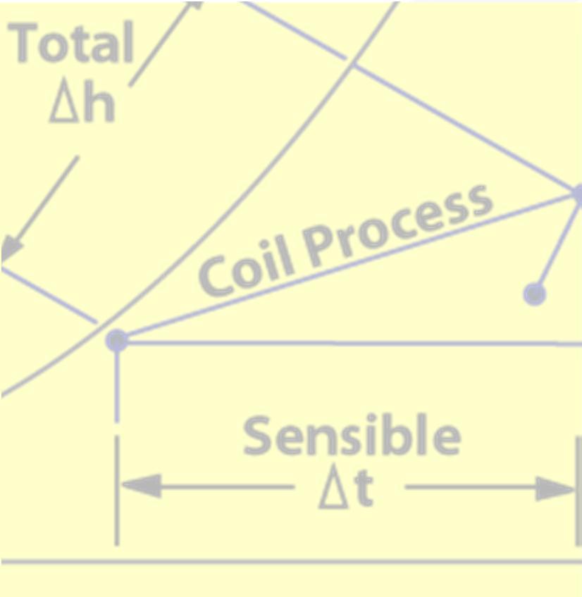
61 Heat Absorbed By Water Air Outlet Q Q Inlet = 500 * gpm * Rise = The total heat absorbed by the water (Btuh) 500 = 60 min/hr * 8.33 lb/gal * specific heat of 1.0 Btu/lb-F gpm = gallons per minute Rise = The water temperature increase as if flows through the coil Section 5 Heat Transfer and Coil Formulas
62 SECTION 6 COILS: DIRECT EXPANSION, CHILLED WATER, AND HEATING Application Topics
63 Glycol Effects On Cooling Coil Section 6 Application Topics


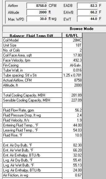
64 Corrosion-Resistant Coil Options Mild Coastal Severe Coastal Severe Industrial Pre-Coat Fins Copper Fins E-Coat Coils Most Economical Choice Most Durable Option Best Baked-on coating applied to fins before coil is assembled. Inhibits galvanic corrosion. All copper construction. Corrosion-inducing bi-metallic joints eliminated. Eliminates galvanic corrosion. Best choice for seacoast. Precisely controlled epoxy dip process for entire assembled coils and headers. Impermeable coating best protects entire coil in harshest environments. Section 6 Application Topics
65 Coil Maintenance and IAQ Chemical treatment of fluid being circulated Sloped Drain Pan Section 6 Application Topics
66 Stacked Coils Header Baffle Hairpin Baffle Intermediate Sloping Drain Pan ¼ /ft min Side Enclosure Clamps Side Enclosure Bottom Sloping Drain Pan ¼ /ft min Floor Enclosure Curb Drain Pipe To Approved Drain Section 6 Application Topics
67 Water Coil Methods 2-Way Valve Supply Return Shutoff Valve Shutoff Valve Control Valve (2-Position On/Off, 2-Way Modulating) 2-Way Control Valve Open/close applications where tight temperature control is not required Commonly used in variable flow applications Balancing Valve Pete s Plug (Typical) Air-Handling Unit Coil Flange or Union Drain Valve Section 6 Application Topics
68 Water Coil Methods 3-Way Mixing Valve Supply Return Shutoff Valve Shutoff Valve Control Valve 3-Way Mixing 3-Way Control Valve Constant flow systems Balancing Valve Balancing Valve Pete s Plug (Typical) Air-Handling Unit Coil Flange or Union Drain Valve Section 6 Application Topics


")


69 Typical Steam Coil Piping Detail Shut-Off Valve Strainer Control Valve Steam Coil Steam Union (Typical) Float and Thermostatic Trap Assembly Vacuum Breaker Condensate Return Dirt Pocket Section 6 Application Topics
70 SECTION 7 COILS: DIRECT EXPANSION, CHILLED WATER, AND HEATING Cooling Coil Design Parameters
71 Load estimating and Coil Selection A good load estimate is the foundation for good coil selection It establishes the capacity requirements for the HVAC system It is used to develop the psychometric analysis necessary to determine coil selection parameters Ensures that the system will meet sensible and latent load requirements of the building to maintain both temperature and humidity Section 7 Cooling Coil Design Parameters
72 Cooling Coil Process Coil process line typical 6 row coil: First few rows provide mosty sensible capacity Last rows produce more latent capacity Air leaves coil close to saturation line Proximity to saturation depends on bypass factor Bypass factor function of: Face velocity Rows Fin spacing Coil Process Line Coil Leaving Air 2 t ra t ma oa Coil Entering Air Air Side Coil Performance t Section 7 Cooling Coil Design Parameters
73 SECTION 8 COILS: DIRECT EXPANSION, CHILLED WATER, AND HEATING Coil Selections
74 Select a Chilled Water Coil Air System Sizing Summary for Typical Floor all zones Project Name: Example 9 Story office 04/29/2004 Prepared by: 04:39PM Air System Information Air System Name...Typical Floor all zones Equipment Class. CW AHU Air System Type VAV Number of zones Equipment Class ft 2 Sizing Calculation Information Zone and Space Sizing Method: Zone cfm.. Peak zone sensible load Space cfm..individual peak space loads Calculation Months.... Jan to Dec Sizing Data... Calculated Central Cooling Coil Sizing Data Total coil load Tons Total coil load MBH Sensible coil load MBH Coil cfm at Aug CFM Max block CFM at Aug CFM Sum of peak zone CFM CFM Sensible heat ratio ft 2 /Ton BTU/(hr-ft 2 ) Water 10.0 F rise gpm Load occurs at. Aug 1500 OA DB / WB / 74.0 F Entering DB / WB 82.3 / 66.2 F Leaving DB / WB / 55.1 F Coil ADP F Bypass Factor Resulting RH.. 42 % Design supply temp F Zone T-stat Check.. 12 of 12 OK Max zone temperature deviation F Indicates data used for coil selection Section 8 Coil Selections

75 COIL SELECTION BROWSE MODE FPM < 500 TC = 280,000 BTUH SHC = 234, 200 BTUH EAT = 82.3 F. / 66.2 F. LAT = 56.0 F. / 55.1 F. GPM = 59.6 TEMP RISE = 10 F.

76 Altitude Effects Example

77 Direct Expansion Coil Selection AHU Builder Selection Software Data Inputs: Select Condensing Unit Program will balance coils with condensing unit Input Coil Selection Parameters from Load Estimate: Coil split type Condensing unit data Section 8 Coil Selections

78 Direct Expansion Coil Selection AHU Builder Selection Software Results: Compare performance to load requirements: TC = MBtuh SHC = MBtuh Coils meet capacity requirements: Tons/circuit (Optimum range (0.8 to 2.0)) Half Circuit better Better for low-load 4/14/HF and 6/8/HF meet specs and is most economical Section 8 Coil Selections
79 Direct Expansion Coil Selection Check Final Selection: 4 row, 11 fins per inch, half circuit coil Design tons/circuit = 1.73 TXV quantity =2 Condensing Unit Unloading Capability: Unloading Capability: 67% of full load Check Part Load Operation: To establish coil split control requirements Tons / circuit Tons / circuit Tons / circuit * Minimum Unloading * Total = Number of TXVs active 1.73 * 0.67 * 2 = 2 = 1.16 (OK without staging) #TXVs If result was below minimum, one TXV must must be closed when compressor unloads Section 8 Coil Selections
 Section 8 Coil")
80 Hot Water Coil Selection Entering Air Temperature (EAT) and Entering Water Temperature (EWT) should be entered prior to running performance Enter the fluid flow and allow the performance software to run the coil capacity based on that flow Enter the system airflow and the maximum allowable coil water pressure drop (WPD) Section 8 Coil Selections

81 Hot Water Coil Selection Best available shows a heating capacity of 347 MBH (Btuh) and 90.3 F. leaving air temperature. This is short of our requirements. Section 8 Coil Selections
 than the required 350 MBH.")
82 Hot Water Coil Selection 2 Row coil displays heating capacities much higher (451 MBH) than the required 350 MBH. Section 8 Coil Selections

83 Hot Water Coil Selection Reducing EWT from 180 F. to 160 F. Section 8 Coil Selections
.")
84 Hot Water Coil Selection Change fluid temp difference for 20 F. to 30 F. (lowering GPM). Section 8 Coil Selections
85 Summary Identified where coils are used in HVAC applications Defined the component parts of coils and typical coil terminology Described the various types of heating and cooling coils Identified the heat transfer formulas and properties of coils Demonstrated the proper use of coils in a variety of applications Described methods to control water and direct expansion coils Identified key coil selection criteria and factors affecting performance Chilled water, DX and Hot Water selections Section 10 Summary
86 Technical Development Program Thank You This completes the presentation. TDP 614 Coils: DX, Chilled Water, and Heating Artwork from Symbol Library used by permission of Software Toolbox
COMMERCIAL HVAC EQUIPMENT Coils: Direct Expansion, Chilled Water, and Heating
 COMMERCIAL HVAC EQUIPMENT Coils: Direct Expansion, Chilled Water, and Heating Technical Development Program Technical Development Programs (TDP) are modules of technical training on HVAC theory, system
Technical Development Program. COMMERCIAL HVAC PACKAGED EQUIPMENT Split Systems PRESENTED BY: Ray Chow Sigler
 Technical Development Program COMMERCIAL HVAC PACKAGED EQUIPMENT Split Systems PRESENTED BY: Ray Chow Sigler Menu Section 1 Section 2 Section 3 Section 4 Section 5 Section 6 Section 7 Introduction System
Introduction to HVAC. American Standard Inc Air Conditioning Clinic TRG-TRC018-EN
 Introduction to HVAC Agenda Psychrometrics Human Comfort Heat Transfer Refrigeration Cycle HVAC Terminology HVAC Systems Introduction to HVAC Psychrometrics 2000 TRG-TRC002-EN Properties of Air Dry-bulb
Air System Sizing Summary for Lobby System Project Name: Existing Lobby 04/04/2005 Prepared by: psuae
 APPENDIX C Air System Sizing Summary for Lobby System Project Name: Existing Lobby 04/04/2005 12:56PM Air System Information Air System Name Equipment Class Air System Type Lobby System CW AHU SZCAV Number
Product Data. Features/Benefits. OMNIZONE 50BRN,BZN Water-Cooled and Remote Air-Cooled Indoor Self-Contained Systems. 5 to 20 Nominal Tons
 Product Data OMNIZONE 50BRN,BZN006-024 Water-Cooled and Remote Air-Cooled Indoor Self-Contained Systems 5 to 20 Nominal Tons The 50BRN,BZN water-cooled and remote air-cooled indoor, self-contained units
Brown University Revised August 3, 2012 Facilities Design & Construction Standards SECTION AIR HANDLING UNITS
 SECTION 23 70 00 AIR HANDLING UNITS PART 1. GENERAL 1.1 Section includes air-handling units to 15,000 cfm and accessories. 1.2 Related Sections 1 : A. Division 01 - Brown University Standard for Narragansett
Product Data. Features/Benefits. GEMINI 38AKS Commercial Air-Cooled Split Systems 50/60 Hz. 25 to 40 Nominal Tons (82.8 to 127.
 Product Data GEMINI 38AKS028-044 Commercial Air-Cooled Split Systems 50/60 Hz 25 to 40 Nominal Tons (82.8 to 127.0 kw) These dependable split systems match Carrier s indoor-air handlers with outdoor condensing
Air-Handling System Cooling Options
 Air-Handling System Cooling Options High-Capacity, Economical Evaporative Cooling High-Efficiency, DX & CW Mechanical Cooling Pure and Simple Solutions AbsolutAire Air-Handling System Cooling Options Economical
Copyright 2003 and 2005 by The American Institute of Architects (AIA) Modified by MSU Physical Plant / Engineering and Architectural Services
 Modified by MSU Physical Plant / Engineering and Architectural Services") Page 238216-1 Copyright 2003 and 2005 by The American Institute of Architects (AIA) Exclusively published and distributed by Architectural Computer Services, Inc. (ARCOM) for the AIA Modified by MSU Physical
Page 238216-1 Copyright 2003 and 2005 by The American Institute of Architects (AIA) Exclusively published and distributed by Architectural Computer Services, Inc. (ARCOM) for the AIA Modified by MSU Physical
G Series. G Series Air Coils Installation ti Manual ENCASED/UNCASED AIR COILS. Geothermal/Water Source Heat Pumps R-410A Refrigerant 2-5 Ton
 G Series ENCASED/UNCASED AIR COILS Geothermal/Water Source Heat Pumps R-410A Refrigerant 2- Ton Dimensional Data G Series Air Coils Installation ti Manual Installation Information Maintenance IM1018AG1
D-PAC. Digital Precise Air Control System. Functionality Factory Testing Ease of Installation Ease of Maintenance Energy Efficiency
 Digital Precise Air Control System D-PAC Functionality Factory Testing Ease of Installation Ease of Maintenance Energy Efficiency AAON 24 South Yukon Avenue Tulsa, Oklahoma 747 (918) 583-2266 Fax (918)
MAC-120HE-03 Air-Cooled Chiller
 MAC-120HE-03 Air-Cooled Chiller 10 Ton / 120,000 BTUH Air-Cooled Chiller 380/415/460-3-50/60 1 HVAC Guide Specifications Air-Cooled Liquid Chiller Nominal Size: 10 Tons Multiaqua Model Number: MAC-120HE-03
Technical Development Program COMMERCIAL HVAC SYSTEMS. Water Source Heat Pump Systems PRESENTED BY: Ray Chow. Sales Engineer
 Technical Development Program PRESENTED BY: COMMERCIAL HVAC SYSTEMS Water Source Heat Pump Systems Ray Chow Sales Engineer TDP Updates Menu Section 1 Section 2 Section 3 Section 4 Section 5 Section 6 Section
Product Data. Features/Benefits. 28CB, 28LA Direct-Expansion. evaporator coils. 7 1 / 2 and 10 Nominal Tons Cooling
 Product Data 28CB, Direct-Expansion Evaporator Coils 7 1 / 2 and 10 Nominal Tons Cooling 28CB Direct-expansion evaporator coils easily accommodate upflow or horizontal light-commercial applications Features/Benefits
MHNCCW (4-Pipe) Chilled/Hot Water Ceiling Concealed 208/230V 4-Pipe Heating & Cooling Fan Coil 12,000 BTUH
 Chilled/Hot Water Ceiling Concealed 208/230V 4-Pipe Heating & Cooling Fan Coil 12,000 BTUH") MHNCCW-04-01 (4-Pipe) Chilled/Hot Water Ceiling Concealed 208/230V 4-Pipe Heating & Cooling Fan Coil 12,000 BTUH Rev. 1.2 HVAC Guide Specifications Chilled and Hot Water Fan Coil 4-Pipe Nominal Size: 12,000
MHNCCW-04-01 (4-Pipe) Chilled/Hot Water Ceiling Concealed 208/230V 4-Pipe Heating & Cooling Fan Coil 12,000 BTUH Rev. 1.2 HVAC Guide Specifications Chilled and Hot Water Fan Coil 4-Pipe Nominal Size: 12,000
Energy Use in Refrigeration Systems
 2012 Rocky Mountain ASHRAE Technical Conference Energy Use in Refrigeration Systems PRESENTED BY: Scott Martin, PE, LEED AP BD+C Objectives Understand mechanical refrigeration terms Describe how heat is
RT-OA TM Rooftop Outdoor-Air (DOAS)
") RT-OA TM Rooftop Outdoor-Air (DOAS) A/C s & HEAT PUMPS Dedicated Outside-Air System (DOAS) Solutions Office Buildings, Schools, Hospitals, Restaurants, Gyms & Fitness Centers, Hotels, Retail Stores...!
RT-OA TM Rooftop Outdoor-Air (DOAS) A/C s & HEAT PUMPS Dedicated Outside-Air System (DOAS) Solutions Office Buildings, Schools, Hospitals, Restaurants, Gyms & Fitness Centers, Hotels, Retail Stores...!
MHNCCX DX with Hot Water Heat Ceiling Concealed 4-Pipe Heat / Cool Fan Coil 12,000-36,000 BTUH
 MHNCCX DX with Hot Water Heat Ceiling Concealed 4-Pipe Heat / Cool Fan Coil 12,000-36,000 BTUH 318 MHNCCX NOMENCLATURE BREAKDOWN 4-Pipe Heat/Cool Ceiling Concealed Fan Coil MHNCCW- XX - XX Ceiling Concealed
Chiller Plant Design. Julian R. de Bullet President debullet Consulting
 Chiller Plant Design Julian R. de Bullet President debullet Consulting 703-483-0179 julian@debullet.com This ASHRAE Distinguished Lecturer is brought to you by the Society Chapter Technology Transfer ASHRAE
1.1 This section applies to air handling units for HVAC Systems.
 AIR HANDLING UNITS GENERAL INFORMATION 1.1 This section applies to air handling units for HVAC Systems. DESIGN REQUIREMENTS 2.1 Design Criteria a. The decision to use modular central station air handling
MHCCW Chilled Water Ceiling Concealed With 5kW Electric Heat 2-Pipe Heat / Cool Fan Coil 30,000 BTUH
 MHCCW-10-05 Chilled Water Ceiling Concealed With 5kW Electric Heat 2-Pipe Heat / Cool Fan Coil 30,000 BTUH Rev. 1.21 HVAC Guide Specifications Chilled Water Fan Coil with Electric Heat 2-Pipe Nominal Size:
Greenheck Coils A Complete Line of Custom Coils to Meet Your Needs. 3/8, 1/2 and 5/8 inch OD Tubing
 Greenheck Coils A Complete Line of Custom Coils to Meet Your Needs 3/8, 1/2 and 5/8 inch OD Tubing April 2012 Custom Coils Custom Coils Configured to Meet Your Needs Greenheck is proud to offer a complete
50TM TFF COMBINATION HEATING/COOLING UNITS
 50T-1SB 50TM007-012 50TFF004-014 COMBINATION HEATING/COOLING UNITS PERFORMANCE DATA CERTIFIED DIMENSION PRINTS CERTIFIED ROOF CURB DIMENSION PRINTS Copyright 2002 Carrier Corporation Syracuse, New York
MHCCW Chilled Water Ceiling Concealed Without Electric Heat 2-Pipe Heat / Cool Fan Coil 18,000 BTUH
 MHCCW-06-00 Chilled Water Ceiling Concealed Without Electric Heat 2-Pipe Heat / Cool Fan Coil 18,000 BTUH Rev. 1.21 HVAC Guide Specifications Chilled or Hot Water Fan Coil 2-Pipe Nominal Size: 18,000 BTUH
VERSECON Indoor Vertical Self-Contained Air Conditioner YSWU Ton Water-Cooled
 FORM 145.05-EG1 (1004) VERSECON Indoor Vertical Self-Contained Air Conditioner YSWU 10 105 Ton Water-Cooled Table of Contents FORM 145.05-EG1 (0804) Features and Benefits.....................................................
MAC-060HE-01-L High Efficiency Air-Cooled Chiller Air-Cooled Chillers for Global Residential and Light Commercial Micro Climates Rev 1.
 MAC-060HE-01-L High Efficiency Air-Cooled Chiller Air-Cooled Chillers for Global Residential and Light Commercial Micro Climates Rev 1.2 HVAC Guide Specifications Air-Cooled Liquid Chiller with Low Ambient
ENGINEERING GUIDE. Water-Cooled Self-Contained Units C-Series, Vertical
 ENGINEERING GUIDE Water-Cooled Self-Contained Units C-Series, Vertical TABLE OF CONTENTS Introduction...2 Product Overview...3 Nomenclature...4 General Data...5 Cooling Performance Data....6 Evaporator
50TM COMBINATION HEATING/COOLING UNITS
 50TM-1SB 50TM004-014 COMBINATION HEATING/COOLING UNITS PERFORMANCE DATA CERTIFIED DIMENSION PRINTS CERTIFIED ROOF CURB DIMENSION PRINTS Copyright 2002 Carrier Corporation Syracuse, New York 13221 Form
COMMON WATERSIDE ECONOMIZER APPLICATIONS:
 APPLICATION MANUAL WATERSIDE ECONOMIZER TABLE OF CONTENTS Safety Approvals...1 Common Waterside Economizer Applications...1 Sequence of Operation (Single)...1 Cooling Mode...2 Heating Mode...2 Sequence
Models PF1A PF1B PACKAGED AIR-HANDLING UNITS. 6to10Tons. Form No. PDS PF1A.72.1 FEATURES/BENEFITS
 PACKAGED AIR-HANDLING UNITS Models PF1A PF1B 6to10Tons PF1A072-120 PF1B090 FEATURES/BENEFITS Multi-position design can be installed horizontally or vertically without modification Standard sloped drain
CARRIER edesign SUITE NEWS. Interpreting High (Low) Peak Design Airflow Sizing Results for HVAC. Equipment Selection.
 Peak Design Airflow Sizing Results for HVAC. Equipment Selection.") Volume 5, Issue 1 CARRIER edesign SUITE NEWS Interpreting High (Low) Peak Design Airflow Sizing Results for HVAC Equipment Selection A design challenge sometimes occurs when computing design loads using
Volume 5, Issue 1 CARRIER edesign SUITE NEWS Interpreting High (Low) Peak Design Airflow Sizing Results for HVAC Equipment Selection A design challenge sometimes occurs when computing design loads using
K*ES120 DESCRIPTION TECHNICAL GUIDE SPLIT-SYSTEM EVAPORATOR BLOWERS 10 NOMINAL TONS EER 8.5 ACCESSORIES FIELD INSTALLED TABLE 1: ARI RATINGS*
 TECHNICAL GUIDE SPLIT-SYSTEM EVAPORATOR BLOWERS K*ES120 10 NOMINAL TONS EER 8.5 DESCRIPTION These completely assembled dual circuit evaporator blower units include a well-insulated cabinet, a DX cooling
MECHANICAL INFRASTRUCTURE ASSESSMENT FOR VICTOR VALLEY COLLEGE
 MECHANICAL INFRASTRUCTURE ASSESSMENT FOR VICTOR VALLEY COLLEGE 18422 Bear Valley Road Victorville, CA 92395 Date 25 September 2012 dha Job No. 12155 TABLE OF CONTENTS I. Purpose.... Page 1 II. Existing
Product Data FEATURES/BENEFITS 524J***H 6 TO 20 TON DIRECT EXPANSION PACKAGED HEAT PUMP AIR -HANDLING UNIT. Indoor air quality features 524J-H 07-12
 524J***H 6 TO 20 TON DIRECT EXPANSION PACKAGED HEAT PUMP AIR -HANDLING Product Data the environmentally sound refrigerant Certified to ISO 9001 524J-H 07-12 524J-H 16-25 C10899 Bryant s versatile packaged
COMMERCIAL HVAC PACKAGED EQUIPMENT. Split Systems
 COMMERCIAL HVAC PACKAGED EQUIPMENT Split Systems Technical Development Programs (TDP) are modules of technical training on HVAC theory, system design, equipment selection and application topics. They are
Product Data. Features/Benefits. 28CB, 28LA Direct-Expansion. evaporator coils. 7 1 / 2 and 10 Nominal Tons Cooling
 Product Data 28CB, 28LA Direct-Expansion Evaporator Coils 7 1 / 2 and 10 Nominal Tons Cooling 28CB Copyright 2001 Carrier Corporation 28LA Direct-expansion evaporator coils that easily accommodate upflow
MAC-036HE-02-L High Efficiency Air-Cooled Chiller Air-Cooled Chillers for Global Residential and Light Commercial Micro Climates Rev 1.
 MAC-036HE-02-L High Efficiency Air-Cooled Chiller Air-Cooled Chillers for Global Residential and Light Commercial Micro Climates Rev 1.1 HVAC Guide Specifications Air-Cooled Liquid Chiller with Low Ambient
MAC-048HE-01-L High Efficiency Air-Cooled Chiller Air-Cooled Chillers for Global Residential and Light Commercial Micro Climates Rev 1.
 MAC-048HE-01-L High Efficiency Air-Cooled Chiller Air-Cooled Chillers for Global Residential and Light Commercial Micro Climates Rev 1.1 HVAC Guide Specifications Air-Cooled Liquid Chiller with Low Ambient
Greenheck Coils A Complete Line of Custom Coils to Meet Your Needs. 5/16, 3/8, 1/2, 5/8 and 1 inch OD Tubing
 Greenheck Coils A Complete Line of Custom Coils to Meet Your Needs 5/16, 3/8, 1/2, 5/8 and 1 inch OD Tubing April 2016 Custom Coils Custom Coils Configured to Meet Your Needs Greenheck is proud to offer
Greenheck Coils. A Complete Line of Custom Coils to Meet Your Needs. 3/8, 1/2 and 5/8 inch OD Tubing
 Greenheck Coils A Complete Line of Custom Coils to Meet Your Needs 3/8, 1/2 and 5/8 inch OD Tubing March 2010 Custom Coils Custom Coils Configured to Meet Your Needs Greenheck is proud to offer a complete
Complete HVAC Capability. Central Station Air Handling Units. Publication No. WT-CSX-0616A
 Publication No. WT-CSX-0616A Central Station Air Handling Units Complete HVAC Capability Horizontal Draw-Thru to Size 65 Vertical Draw-Thru to Size 50 1000 to 60,000 CFM Forward Curved or Airfoil Wheels
CHAPTER 4. HVAC DELIVERY SYSTEMS
 CHAPTER 4. HVAC DELIVERY SYSTEMS 4.1 Introduction 4.2 Centralized System versus Individual System 4.3 Heat Transfer Fluids 4.4 CAV versus VAV Systems 4.5 Common Systems for Heating and Cooling 4.6 Economizer
Air-Handling System Cooling Options
 Air-Handling System Cooling Options High-Capacity, Economical Evaporative Cooling High-Efficiency, DX & CW Mechanical Cooling Pure and Simple Solutions AbsolutAire Air-Handling System Cooling Options Economical
Andrea Borowski The Pennsylvania State University University Park, PA November 11, 2002 Consultant: Dr. Bahnfleth Technical Assignment M-3
 Existing System Evaluation Executive Summary The MBNA Career Services Center is a 44,000 square foot, 4-story office type building at Penn State University, University Park Campus. The building is located
VertiCool Aurora Engineering Guide
 Engineering Guide Effective August 2016 Air-Cooled, Water-Cooled and Water Source Heat Pump Contents Product Features... 3 Options... 4 Physical Data...5-6 Air-Cooled Performance Data (a) (b) (c)...7-8
General Catalogue. FORM SSI - G.C (94)
") FORM SSI - G.C (94) www.ssi.co.ir General Catalogue INDEX 09CDF 16DNS 16DES 16JBP 16JBP Air Cooled Condenser Air Cooled Condenser Absorption Chiller Double Effect Direct Fired Absorption Chiller Double
FORM SSI - G.C (94) www.ssi.co.ir General Catalogue INDEX 09CDF 16DNS 16DES 16JBP 16JBP Air Cooled Condenser Air Cooled Condenser Absorption Chiller Double Effect Direct Fired Absorption Chiller Double
BRINE CIRCULATED ICE THERMAL STORAGE SYSTEM DESIGN - CASE ILLUSTRATION - Partial Ice Storage for Air Conditioning Application
 1 BRINE CIRCULATED ICE THERMAL STORAGE SYSTEM DESIGN - CASE ILLUSTRATION - Partial Ice Storage for Air Conditioning Application By: T. S. Wan Date: Oct. 7, 1995 Copy Right 1995 by T. S. Wan All rights
H3/V3 Series Horizontal and Vertical Indoor Air Handling Units. Engineering Catalog
 H3/V3 Series Horizontal and Vertical Indoor Air Handling Units Engineering Catalog Table of Contents AAON H3/V3 Series Features and Options Introduction... 6 H3/V3 Base Model Description... 7 Unit Size...
VariCool VAV Engineering Guide
 Engineering Guide Effective September 2017 Water-Cooled and Chilled Water, Variable Air Volume Contents Product Features... 3 UNIT FEATURES... 3 Product Features... 4 Marvel Plus Microprocessor Control
TECHNICAL GUIDE. Description SPLIT-SYSTEM AIR-COOLED CONDENSING UNITS YD360, 480 & THRU 50 NOMINAL TONS YTG-B-0811
 Description These units are completely assembled, piped and wired at the factory to provide one-piece shipment and rigging. Each unit is pressurized with a holding charge of Refrigerant R-410A for storage
Pharmaceutical Facility Design
 PhEn-602 Pharmaceutical Facility Design J. Manfredi Notes 9A PhEn-602 J. Manfredi 1 Primary & Secondary HVAC units Primary Primary air handling unit arrangement: One unit is responsible for all of the
CFFWA4P-08-1-U Chilled/Hot Water Universal Mount Fan Coil (4-Pipe) 4-Pipe Heat / Cool Fan Coil 24,000 BTUH
 4-Pipe Heat / Cool Fan Coil 24,000 BTUH") CFFWA4P-08-1-U Chilled/Hot Water Universal Mount Fan Coil (4-Pipe) 4-Pipe Heat / Cool Fan Coil 24,000 BTUH Rev. 1.3 HVAC Guide Specifications Chilled and Hot Water Universal Mount Fan Coil 4-Pipe Nominal
CFFWA4P-08-1-U Chilled/Hot Water Universal Mount Fan Coil (4-Pipe) 4-Pipe Heat / Cool Fan Coil 24,000 BTUH Rev. 1.3 HVAC Guide Specifications Chilled and Hot Water Universal Mount Fan Coil 4-Pipe Nominal
COOLING / HEATING COILS
 COOLING / HEATING COILS GENERAL INSTALLATION OPERATION AND MAINTENANCE COIL TYPES CHILLED WATER / GLYCOL HOT WATER / GLYCOL DIRECT EXPANSION (EVAPORATIVE COOLING) STEAM DISTRIBUTING STANDARD STEAM Type
SECTION 5 COMMERCIAL REFRIGERATION UNIT 22 CONDENSERS UNIT OBJECTIVES UNIT OBJECTIVES 3/22/2012
 SECTION 5 COMMERCIAL REFRIGERATION UNIT 22 CONDENSERS UNIT OBJECTIVES After studying this unit, the reader should be able to explain the purpose of the condenser in a refrigeration system. describe differences
COMMERCIAL PACKAGED HEAT PUMP AIR HANDLER UNITS, 6 20 TONS
 Product Specifications COMMERCIAL PACKAGED HEAT PUMP AIR HANDLER S, 6 20 TONS BUILT TO LAST, EASY TO INSTALL AND SERVICE Multi position design for horizontal or vertical installation without modification.
Product Data. Features/Benefits. 50HS Single-Package Heat Pump Units 50 Hz
 Product Data 50HS Single-Package Heat Pump Units 50 Hz Nominal: 7 to 18 kw (2 to 5 Tons) Single-Package Heat Pump for Manufactured Housing/Residential and Light Commercial use. Features/Benefits One-piece
Dehumidifying with Dedicated Outdoor Air
 Dehumidifying with Dedicated Outdoor Air System Configurations Figure 71. Configurations for dedicated outdoor-air systems A dedicated outdoor-air handler separately filters, cools, dehumidifies, heats,
Air System Sizing Summary for AHU/CU-1 Project Name: Wilton Manors Fire Station#16 06/26/2016 Prepared by: L.N.I.
 Air System Sizing Summary for AHU/CU-1 AHU/CU-1 Floor Area 1678.0 ft² Central Cooling Coil Total coil load 4.8 Tons Total coil load 57.8 MBH Sensible coil load 41.8 MBH Coil CFM at Jul 1500 1909 CFM Max
2. CURRICULUM. Sl. No.
 . CURRICULUM Sl. No. Code Title No. of Lecture Hours 1 RAC 001 Fundamentals of Refrigeration and Air 60 conditioning RAC 00 Psychrometry, Heat load Estimation for 70 Air conditioning and Refrigeration
15 SEER SINGLE- PACKAGED HEAT PUMP SYSTEM WITH PURON
 7D- -A EVOLUTIONr 15 SEER SINGLE-PACKAGED HEAT PUMP SYSTEM WITH PURONr (R-410A) REFRIGERANT SINGLE PHASE 2-5 NOMINAL TONS (SIZES 24-) Fig. 1 - Unit 7D - -A Product Data A09032 Single-Packaged Products
SPLIT SYSTEMS SELECTION & OPTIMIZATION GUIDE
 SPLIT SYSTEMS SELECTION & OPTIMIZATION GUIDE www.addison-hvac.com Creating a New Project 1. Open the ACE Interface within the web browser. ACE performs best using the Google Chrome browser. Do not use
CFFWA4P-16-1-U Chilled/Hot Water Universal Mount Fan Coil (4-Pipe) 4-Pipe Heat / Cool Fan Coil 48,000 BTUH
 4-Pipe Heat / Cool Fan Coil 48,000 BTUH") CFFWA4P-16-1-U Chilled/Hot Water Universal Mount Fan Coil (4-Pipe) 4-Pipe Heat / Cool Fan Coil 48,000 BTUH Rev. 1.3 HVAC Guide Specifications Chilled and Hot Water Universal Mount Fan Coil 4-Pipe Nominal
CFFWA4P-16-1-U Chilled/Hot Water Universal Mount Fan Coil (4-Pipe) 4-Pipe Heat / Cool Fan Coil 48,000 BTUH Rev. 1.3 HVAC Guide Specifications Chilled and Hot Water Universal Mount Fan Coil 4-Pipe Nominal
CTI Sponsored Educational Program
 Presented By: Kent Martens SPX Cooling Technologies, Inc. Slide No.: 1 CTI Mission Statement To advocate and promote the use of environmentally responsible Evaporative Heat Transfer Systems (EHTS) for
CFFWA4P-12-1-U Chilled/Hot Water Universal Mount Fan Coil (4-Pipe) 4-Pipe Heat / Cool Fan Coil 36,000 BTUH
 4-Pipe Heat / Cool Fan Coil 36,000 BTUH") CFFWA4P-12-1-U Chilled/Hot Water Universal Mount Fan Coil (4-Pipe) 4-Pipe Heat / Cool Fan Coil 36,000 BTUH Rev. 1.3 HVAC Guide Specifications Chilled and Hot Water Universal Mount Fan Coil 4-Pipe Nominal
CFFWA4P-12-1-U Chilled/Hot Water Universal Mount Fan Coil (4-Pipe) 4-Pipe Heat / Cool Fan Coil 36,000 BTUH Rev. 1.3 HVAC Guide Specifications Chilled and Hot Water Universal Mount Fan Coil 4-Pipe Nominal
SECTION AIR COILS
 PART 1 - GENERAL 1.1 RELATED DOCUMENTS A. Drawings and general provisions of the Contract, including General and Supplementary Conditions and Specification Sections, apply to this Section. B. Related Sections:
AIR-CONDITIONING SYSTEMS AND APPLICATIONS. Abdullah Nuhait Ph D. King Saud University
 AIR-CONDITIONING SYSTEMS AND APPLICATIONS Abdullah Nuhait Ph D. King Saud University AIR-CONDITIONING SYSTEMS Earliest air conditioning system used only for heating (winter) Provided heated air for comfort
Water-Cooled Self-Contained Units
 CATALOG FORM SK145.15-EG1 (1017) Water-Cooled Self-Contained Units C-Series, Vertical Nomenclature WATER-COOLED SELF-CONTAINED UNIT 1, 2 3 4, 5, 6 7 8 9 10 11 12 13 14 15 16 17 CS V 180 B 2 M 1 V A A A
Compact, Self-Contained unit that offer low installation cost plus dependable performance.
 0 Compact, Self-Contained unit that offer low installation cost plus dependable performance. From carrier s excellence in engineering come a new, compact of single package horizontal and vertical water
C13-Series Engineering Guide
 Engineering Guide Effective January 2018 Horizontal Air-Cooled, Water-Cooled, Chilled Water and Heat Pump Contents Product Features............................... 3 Product Options................................
Product Data. 50HS Single-Package Heat Pumps to 5 Nominal Tons
 Product Data 50HS Single-Package Heat Pumps 1 1 2 to 5 Nominal Tons Single-Package Heat Pump for Manufactured Housing/Residential and Light Commercial use. Features/Benefits One-piece heat pumps with optional
Modular Active. Chilled. Beams
 Modular Active Chilled Beams How Twa MAC Beams Work Primary air (100% outside air) is dehumidified to between 50-57 F dew point and is used to: control the latent requirements of the space, provide fresh
BOOK 1 OVERVIEW RD2XRT INSTALLATION AND OPERATION MANUAL. Table of Contents ABOUT BOOK 1:
 4510 Helgesen Drive, Madison, WI, 53718 608.221.4499, 800.627.4499, Fax: 608.221.2824 support@renewaire.com www.renewaire.com RD2XRT INSTALLATION AND OPERATION MANUAL BOOK 1 OVERVIEW ABOUT BOOK 1: This
TECHNICAL GUIDE DESCRIPTION SPLIT-SYSTEM AIR-COOLED CONDENSING UNITS. HA300, HB360, HB480 & HB thru 50 NOMINAL TONS (50 Hz)
") DESCRIPTION These units are completely assembled, piped and wired at the factory to provide one-piece shipment and rigging. Each unit is pressurized with a holding charge of refrigerant-22 for storage
DESCRIPTION These units are completely assembled, piped and wired at the factory to provide one-piece shipment and rigging. Each unit is pressurized with a holding charge of refrigerant-22 for storage
30GT FLOTRONIC AIR-COOLED CHILLERS
 30GT-41SB 30GT040-110 FLOTRONIC AIR-COOLED CHILLERS PERFORMANCE DATA FIELD WIRING DIAGRAM 1998 Carrier Corporation Syracuse, New York 13221 Form 30GT-41SB Supersedes 30GT-21SB, 30GT-22SB, 30GT-23SB, Printed
Technical Development Program
 Technical Development Program COMMERCIAL HVAC CHILLER EQUIPMENT Water-Cooled Chillers PRESENTED BY: Omar Rojas Sales Engineer Menu Section 1 Section 2 Section 3 Section 4 Section 5 Section 6 Section 7
RoofPak Applied Rooftop Systems
 RoofPak Applied Rooftop Systems RoofPak Applied Rooftop Systems Design flexibility, energy efficiency, system performance and reliability make Daikin RoofPak applied rooftop systems the ideal solution
UNIVERSITY OF MISSOURI Central Station Air-Handling Units March
 GENERAL: 1. This section provides criteria for the design and installation of air handling units. DESIGN GUIDELINES: Design General 1. Location 1.1. For new construction, and existing buildings where possible,
CB/CF. Series CONDENSERS AND CONDENSING UNITS. Features:
 CB/CF CONDENSERS AND CONDENSING UNITS CF CB Features: 2-70 ton air-cooled condensing units and remote air-cooled condensers Air-source heat pump configurations for energy efficient heating Variable capacity
Product Data. 40RUA/40RUS 6to15TonDirectExpansion 7.5to15TonChilledWater Packaged Air---Handling Units FEATURES/BENEFITS. Indoor air quality features
 A/S 6to15TonDirectExpansion 7.5to15TonChilledWater Packaged Air---Handling Units Product Data Carrier s versatile packaged air-handling units satisfy design requirements with: ---, the environmentally
Heat Recovery Units. Heat Recovery 1
 Heat Recovery Units Heat Recovery 1 Heat Recovery Unit Why? A heat recovery unit (HRU) can help make mechanical ventilation more cost effective by reclaiming energy from exhaust airflows. HRUs use air-to-air
DIVISION 15 MECHANICAL
 DIVISION 15 MECHANICAL A. GENERAL DESIGN CONDITIONS 1. Design occupied spaces to maintain 72 F and a space dew point temperature not to exceed 55 F. 2. Design classroom and office space buildings with
DIRECT DRIVE BLOWER COILS
 DIRECT DRIVE BLOWER COILS Horizontal HDY Vertical VDY Upgrade to IEC s Direct Drive Blower Coils Energy Efficient Energy Efficient Easy Easy to Installation Install Extended Service Life Engineered to
Technical Assignment 3 11/15/04. Executive Summary
 Executive Summary This report is an analysis of the existing systems within the Outreach Innovation Building in University Park, PA. One significant design criteria was a lower than average noise criteria
INSTALLATION INSTRUCTIONS TXV Horizontal Duct Coils EHD
 TXV Horizontal Duct s EHD These instructions must be read and understood completely before attempting installation. It is important that the Blower and Duct System be properly sized to allow the system
RN/RQ. Series PACKAGED ROOFTOP UNITS, AIR-SOURCE HEAT PUMPS, WATER-SOURCE/ GEOTHERMAL HEAT PUMPS, & OUTDOOR AIR HANDLING UNITS.
 RN/RQ Series PACKAGED ROOFTOP UNITS, AIR-SOURCE HEAT PUMPS, WATER-SOURCE/ GEOTHERMAL HEAT PUMPS, & OUTDOOR AIR HANDLING UNITS RQ Series Features: Air-cooled or water-cooled condenser, with unit capacities
Fundamentals of Psychrometrics. By James L. Murphy, Colorado Building Environments Sales Engineer
 Fundamentals of Psychrometrics By James L. Murphy, Colorado Building Environments Sales Engineer Let s s Start with Air Air is Made up of Two Main Gases Nitrogen (77%) Oxygen (23%) If that is all there
Daikin Water Cooling, Heating, and High Capacity Booster Coils
 Installation and Maintenance Manual IM 900 Daikin Water Cooling, Heating, and High Capacity Booster Coils Group: Applied Air Part Number: IM 900 Date: February 2008 Types HI-F5, E-F5 2008 Daikin International
Technical Guide SUNLINE 2000 DESCRIPTION ACCESSORIES FIELD INSTALLED SPLIT-SYSTEM EVAPORATOR BLOWER K4EU NOMINAL TONS (WORLD 50 HZ)
") Technical Guide SUNLINE 2000 SPLIT-SYSTEM EVAPORATOR BLOWER K4EU180 15 NOMINAL TONS (WORLD 50 HZ) DESCRIPTION These completely assembled units include a well-insulated cabinet, a DX cooling coil with copper
Technical Guide SUNLINE 2000 SPLIT-SYSTEM EVAPORATOR BLOWER K4EU180 15 NOMINAL TONS (WORLD 50 HZ) DESCRIPTION These completely assembled units include a well-insulated cabinet, a DX cooling coil with copper
VertiCool CLASSIC. Engineering Guide. Effective March Air-Cooled, Water-Cooled, Chilled Water and Water Source Heat Pump
 VertiCool CLASSIC Engineering Guide Effective March 2018 Air-Cooled, Water-Cooled, Chilled Water and Water Source Heat Pump Contents Product Features... 3 UNIT FEATURES... 3 OPTIONS:... 3 Physical Data...
Air Conditioning Clinic
 Air Conditioning Clinic Psychrometry One of the Fundamental Series D C B A C B D A July 2012 TRG-TRC001-EN Psychrometry One of the Fundamental Series A publication of Trane Preface Psychrometry A Trane
CAS. Product Specifications. COMMERCIAL SPLIT SYSTEMS CONDENSING UNITS R 410A, 6 to 12.5 TONS BUILT TO LAST, EASY TO INSTALL AND SERVICE
 COMMERCIAL SPLIT SYSTEMS CONDENSING UNITS R 410A, 6 to 12.5 TONS BUILT TO LAST, EASY TO INSTALL AND SERVICE CAS Product Specifications Single stage cooling capacity control on all models with Micro channel
Product Data PF4MNA DIRECT EXPANSION FAN COIL FOR R -410A REFRIGERANT SIZES 018 THRU 061 FEATURES/BENEFITS AVAILABLE SIZES:
 PF4MNA DIRECT EXPANSION FAN COIL FOR R -410A REFRIGERANT SIZES 018 THRU 061 Product Data FEATURES/BENEFITS AVAILABLE SIZES: 18,000 to 61,000 BTU unit, 1.5 to 5.0 ton unit ELECTRICAL RANGE: 40 -va, 208/230
Microchannel REMOTE AIR COOLED CONDENSER WITH ELECTRONICALLY COMMUTATED AXITOP MOTORS. Technical Bulletin. Products that provide lasting solutions.
 Microchannel REMOTE AIR COOLED CONDENSER WITH ELECTRONICALLY COMMUTATED AXITOP MOTORS Technical Bulletin Products that provide lasting solutions. Krack Corporation has a long tradition of leadership and
Product Data. FPMA Sizes 018 thru 036 FPMB Sizes 018 thru 030 Base Series Horizontal Fan Coil
 FPMA Sizes 018 thru 036 FPMB Sizes 018 thru 030 Base Series Horizontal Fan Coil A13303 Fig. 1 - FPM(A,B)NU Uncased Horizontal Fan Coil (FPMANU model shown) Fig. 2 - FPM(A,B)NC Cased Horizontal Fan Coil
Modular Supply Make-Up Air Unit
 Modular Supply Make-Up Air Unit Model MSX Flexible Design Factory Assembled Heating Options Hot Water Steam Electric Cooling Options Evaporative Direct Expansion Chilled Water November 2009 Product Features
INSTALLATION INSTRUCTIONS TXV Horizontal Slab Coils WLSH
 TXV Horizontal Slab Coils WLSH These instructions must be read and understood completely before attempting installation. It is important that the Blower and Duct System be properly sized to allow the system
Upflow/Downflow A-Coil Specifications
 June 2013 Upflow/Downflow A-Coil Specifications ADP Model # Width Depth Height Pallet Qty. Coil Weight (lbs) C36A142(*)126 14.25" 21" 16.5" 12 38 1200 386.36 C36A175(*)126 17.50" 21" 16.5" 8 40 1200 386.34
GP SERIES Packaged Chillers
 Material Handling Process Cooling Temperature Control Size Reduction Temperature Control Process Cooling Material Handling Size Reduction GP SERIES Packaged Chillers Precision Comprehensive Engineered
Designing Energy Efficient Outdoor Air Systems
 Designing Energy Efficient Outdoor Air Systems Joseph Thorndal Applied Products Sales Manager Greenheck, Schofield, Wisconsin 1 Joseph Thorndal BS Industrial Engineering North Dakota State University Work
Water Piping and Pumps
 Technical Development Program DISTRIBUTION SYSTEMS Water Piping and Pumps PRESENTED BY: Michael Ho carriertdp@gmail.com 424-262-2144 Menu Section 1 Section 2 Section 3 Section 4 Section 5 Section 6 Section