INTRODUCTION THIS MANUAL INCLUDES IMPORTANT SAFETY INFORMATION
|
|
|
- Augusta Simon
- 5 years ago
- Views:
Transcription

")
1 INSTALLATION AND OPERATING INSTRUCTIONS FOR THE HARDY Fuel Oil Furnace Models D-140 & D-350 HARDY MANUFACTURING COMPANY, INC ROAD 505 PHILADELPHIA, MS PHONE: (601) FAX: (601)
2
3 INTRODUCTION Thank you for purchasing the original all stainless steel Hardy Fuel Oil Furnace. It represents the result of many years of Hardy experience and the input of Hardy customers in the production of a top quality furnace. With the purchase of this Hardy Furnace, you can now appreciate the high degree of craftsmanship and reliability that have made The Hardy the leader in the outside Fuel Oil Furnace field. This manual will provide you with a good basic understanding of the installation and operation of this furnace. THIS MANUAL INCLUDES IMPORTANT SAFETY INFORMATION Your new furnace should have the following: 1 Owners Manual complete with installation and hook-up Instructions 2 Warranty & return Warranty Card 3 Condenser tank stack with trim (located inside for shipping) 4 two (2) sections smoke stack with trim 5 Rain cap with spark arrestor screen Should your furnace not have any of these items or if you have any questions regarding the operation or maintenance of your furnace, please consult your local Hardy Dealer. Again, thank you for purchasing a Hardy Furnace Sincerely, Frank L. Moore President Hardy Manufacturing Company Incorporated i
4 Please fill in the following information Hardy Model Serial Number Date of Purchase Date of Installation Dealer Purchased from Dealer Address Dealer Phone Number Please keep this manual with all other important papers. The information in this manual is necessary for the installation, operation and proper use of this unit. If you should ever have a problem or question please refer to this manual or have it available when you call your Hardy Dealer or Hardy Manufacturing Company Incorporated. HARDY MANUFACTURING CO., INC Rd. 505 PHILADELPHIA, MISSISSIPPI PHONE: (601) or (601) FAX: (601) ii
5 SAFETY PRECAUTIONS WARNING Do not operate this equipment for other than its intended purpose nor other than in accordance with the instructions contained in this manual and all other instructions accompanying the unit. For units covered by this instruction book, it is important to observe safety precautions to protect yourself from possible injury. Among the many considerations, you are advised to: Observe all safety stickers on the unit This unit must be wired by a qualified electrician in accordance with the National Electrical Code. Never attempt to use gasoline as a fuel for this burner, as it is more combustible and could result in a serious explosion. Always use proper care when installing, operating and maintaining this unit. Do not modify this unit. Do not substitute parts or repairs which can be provided by your dealer, distributor, or Manufacturing Company. Failure to heed this warning or any additional warnings on this unit may result in an accident causing personal injury. iii
6 THE HARDY OUTSIDE FUEL OIL FURNACE How does an outside furnace heat my home? The Hardy outside fuel oil furnace is designed to save the most energy and provide the most comfortable heating available. It heats your home by heating a stainless steel tank filled with water, which surrounds the firebox of the outside furnace. The furnace is basically a nonpressurized boiler with an atmospheric vent. This hot water is then circulated through underground hot water pipes to a water coil inside your existing central duct system. The Hardy furnace can be connected to any existing hydronic heating system that operates at 180 degrees or less. How does THE HARDY heat water for household use? A cold water supply line goes to the outside furnace. The water line connects to a heat exchanger which is mounted on the rear of the outside furnace. The pressure on the supply water line forces water through the heat exchanger when you open a hot water faucet inside the home. As this water passes through the heat exchanger it picks up the heat from the furnace water which is pumped through one side of this heat exchanger and then returns to the furnace to be reheated. The domestic water then goes to the cold water input on your hot water heater. This means the hot water heater will take on hot water instead of cold. This water is not contaminated with the water that passes through your furnace and coil to heat your house. How do the thermostat controls work? The only visible addition to the heating system inside your home is the thermostat which is located near the existing thermostat. The two thermostats are installed so that if the outside fuel oil furnace is not in operation, your existing unit will automatically take over to maintain your household temperature. The wall thermostat which regulates the heat from the outside furnace performs two functions; when it senses your need for heat according to your temperature setting, it turns the water pump on to circulate the hot water through the coil and also turns the blower on inside your central unit to force air across the hot coil. This forces hot air into your central duct system. The outside furnace has a hot water thermostat which senses the water temperature of the unit. If the water is not as hot as the thermostat setting (normally set on 170 degrees) then the fuel oil burner is automatically fired until such temperature is attained. Where should an outside fuel oil furnace be located? The outside unit should be located at least 10 feet from your home so that all fire danger is removed from your home. The unit may be installed as much as 100 feet away and still heat your house an hot water. If the unit is located more than 100 feet away, you may experience some heat loss on the water going to your hot water heater. Locate the outside furnace where it will be convenient for refueling. All water and power lines are installed underground between the house and the outside fuel oil furnace. iv
7 TABLE OF CONTENTS SECTION I: General Information 1-1 Specifications Page Furnace Dimensions Page Furnace Component Parts (Model HM-140-HW) Page Furnace Component Parts (Model HM-350-HW) Page 3 SECTION II: Important notes to owners 2-1 Warranty Page Codes Page Fuel Page Maintenance Page 4 SECTION III: Installation of furnace 3-1 General Information Page Preparing concrete pad Page 5 Illustration #3A Page Preparing furnace for installation Page Fuel Tank, Fuel Pump, Fuel Lines Page 7 Illustration #3B Page 8 Illustration #3C Page Connection of Power to Furnace Page 9 Illustration #3D Page Installation of Heating Coil Page 10 Illustration #3E Page Plumbing of Heating Coil Page 11 Illustration #3F Page Plumbing of Hydronic Heating System Page 11 Illustration #3G Page Installation of Domestic Water Lines Page 12 Illustration #3H Page 12 v
8 SECTION IV: Electrical Installation Instructions 4-1 Typical Existing Forced Air System with an Existing Blower Relay Page 13 Illustration #4A Page Typical Existing Forced Air System without Existing Blower Relay Page 15 Illustration #4B Page Typical Existing Hydronic Heating System Page Illustration #4C Page 17 Illustration #4D Page 18 SECTION V: Fuel Oil Burner Tips to Serviceman Page Beckett Fuel Oil Burner Page Replacement Parts Page 26 Primary Control Reference Guide Page vi
9 SECTION I GENERAL INFORMATION 1-1 Specifications Type of fuel #1 or #2 fuel oil Maximum fuel consumption HM-140-HW HM-350-HW Furnace rating HM-140-HW HM-350-HW 1.0 GPH 2.5 GPH 140,000 BTU/Hr. Input 350,000 BTU/Hr. Input For Outdoor Use Only Electrical Rating 115 VAC / 60 HZ / 1P MFS 20 AMP, MCA 20 AMP Clearance to combustibles Top, Rear, Sides - 36 Chimney connector - 36 Front - 36 Flooring - Non Combustible 1-2 Furnace Dimensions Description Width Depth Height Weight HM-140-HW ¾ 48 ½ 368 lbs. HM-350-HW ¾ 48 ½ 471 lbs. Page 1


10 1-3 Furnace components (Model HM-140-HW) 5 6 Ref # Part # Description Oil Burner Sight Glass Fuel Filter Power cord Low Water Switch Dayton thermostat Taco 009 Pump Relay Low Water Lockout relay Socket for low water Lockout relay Low water light 1 3 Page 2


11 1-4 Furnace components (Model HM-350-HW) Ref # Part # Description Oil Burner Sight Glass Fuel Filter Power cord Low Water Switch Dayton thermostat Taco 009 Pump Relay Low Water Lockout relay Socket for low water Lockout relay Low water light 1 3 Page 3
12 2-1 WARRANTY SECTION II IMPORTANT NOTES TO OWNERS Fill out the warranty card & return it within 30 days to: 2-2 CODES Hardy Manufacturing Co. Inc Rd. 505 Philadelphia MS All installations must be made in accordance with National, State, and Local codes which may differ from the manual. Installation, Operating, and maintenance permits from each of the above authorities may be required, as well as Municipal permits. 2-3 FUEL This furnace will burn the following approved fuels #1 & #2 fuel Oil (Diesel) Do not add the following materials to your fuel oil: Gasoline Cleaning fluids or solvents Oil additives Antifreeze Do not attempt to start the burner when excess oil, oil vapors, or fumes have accumulated in the firing chamber. Do not store or use gasoline or other flammable vapors or liquids in the vicinity of this or any other appliance. Do not install this furnace on a combustible material of any kind. 2-4 MAINTENANCE Hardy recommends that a factory authorized burner technician service your burner and furnace once a year. Call your Hardy dealer for information concerning Annual Hardy Furnace Maintenance. Do not allow unauthorized, untrained personnel to tamper with your furnace. Page 4
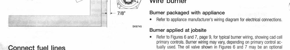
13 SECTION III INSTALLATION OF FURNACE 3-1 GENERAL The following information is general in nature. Furnace installation must be accomplished by qualified personnel and must comply with all applicable national, state, and local codes. Select a furnace location which allows safe and easy access for servicing, fuel storage, and refueling equipment. Furnace must be located a minimum of ten (10) feet from building to be heated, and a maximum of one hundred (100) feet. Smoke stack must be at least two (2) feet higher than peak or highest portion of roof with in ten (10) feet horizontally of stack. 3-2 PREPARING CONCRETE PAD Prepare a concrete pad 36 x 60 with a cutout in pad as shown in layout illustration #3A. Install a four (4) inch or six (6) inch Water tight pipe under pad at the pump end of the pad (this is the minimum insulating requirements). Run water lines, electrical line, and thermostat wire from building to be heated to the furnace through this pipe. Lines required are as follows: 1 12/2 with ground (120 volt / 20 amp) power supply line 2 Hot water lines for each zone (3/4 for forced air systems, 1 for hydronic s.) 2 3/4 hot water lines for domestic hot water if DHW heat exchanger was ordered 1 3 Conductor thermostat wire, at least 18 gauge, for each heat zone. All water lines will come up at pump end of pad. All lines need to be rated for hot water use. A 1/2 minimum fuel line will need to be run to the burner from the fuel storage tank. If the fuel storage tank is to be located below the level of the burner, you will need a return line of the same size as the supply. Both of these lines must be rated for use with oil. Once all lines have been run the cutout in the pad can be filled with sand, up to the level of the pad. Page 5
14 ILLUSTRATION #3A 36" Top Veiw of Concrete Pad 60" 20" 14" 6" 14" 4" Back of Pad Page 6
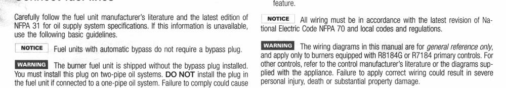
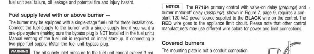
15 3-3 PREPARING FURNACE FOR INSTALLATION Remove the hull from the furnace by lifting the hull straight up, and set it to the side. Cut the shipping straps that attach the furnace to the shipping pallet. Electrical service will need to be a dedicated 120 volt / 20 amp circuit. Heating lines will need to be of any pipe or tubing rated 180 degrees Fahrenheit, 100 psi. pressure. Supply pipe for heating system will hook up to the pump, return pipe will go to return fitting, (one is located at pump end of furnace and two are located at burner end of furnace). Thermostat wires for the heating system control will hook up at the pump end of the furnace. 3-4 FUEL TANK, FUEL PUMP, FUEL LINES Fuel Oil burners supplied with the Hardy Fuel Oil Furnace are provided with a single stage 3450 RPM fuel unit with the by-pass plug removed for single pipe installations. This is satisfactory where the fuel tank is on the same level horizontally, or above the burner, permitting gravity flow of oil. See illustration #3B. Never exceed 3 PSI pressure to the suction side of the fuel unit. A pressure of 8 PSI may cause damage to the shaft seal and allow it to leak oil. When it is necessary to lift the oil to the burner, a return line should be run between the fuel unit and the fuel tank. (If lift exceeds ten (10) feet, a two stage fuel unit must be used with a return line.) When a return line is used, the by-pass plug must be installed. This is supplied along with an information pump data sheet in a plastic bag attached to the fuel pump unit on the burner. See illustration #3C. When oil lines are installed, continuous runs of heavy wall copper tubing is recommended. Be sure that all connections are absolutely air tight. Check all connection and joints. Flared fittings are recommended. Do not use compression fittings. See pump data sheet for sizing, lift, and length for tubing recommendations, 1/2 copper is normal. Install a tank shut off valve at the fuel tank for servicing. Page 7


16 3-4 FUEL TANK, FUEL PUMP, FUEL LINES (cont.) ILLUSTRATION #3B ILLUSTRATION #3C SUNTEC A-7000 Page 8
17 3-5 CONNECTION OF POWER TO FURNACE This unit must be wired by a qualified electrician In accordance with the National Electric Code And any City, State, or Municipality codes Provide a 120 Volt / 20 Amp. Circuit to the furnace. This circuit will connect to the line side of the Ground Fault Interrupter outlet (GFCI) on the back of the furnace. The power wire of the circuit will connect to the brass screw, the neutral wire of the circuit will connect to the silver screw, and the ground wire will connect to the green screw. After the wiring is complete check the receptacle with a circuit tester to determine if the polarity is correct, and to make sure you have a good ground. Press the test button on the GFCI receptacle. The reset button should pop out and the circuit should be interrupted. Press the reset button to restore the circuit to normal operation See Illustration #3D for furnace wiring schematic. ILLUSTRATION #3D Black Red Low Water Switch Thermostat White Pink Blue Red B l a c k Red Relay White Yellow Release White Black Power Cord Low Water Light Optional Water Fill Solenoid Power Cord must be plugged into switched outlet Primary Control on Burner Pink Pink Page 9
18 3-6 INSTALLATION OF HEATING COIL In a forced air system a heating coil will need to be mounted into the existing duct system. This coil needs to be matched to the blower in your system according to air flow ratings. The water coils sold by Hardy can only be mounted with the water connections of the coil in a horizontal plane. Never try to mount the water connections straight up or down. The water lines to the coil should be connected with the supply line, the one coming from the pump, connected to the fitting on the coil that is farthest away from the blower. The return line, the one going back to the furnace will be the line closest to the blower. This will put the hottest water on the side of the coil that has the air leaving it and going into the duct work. See illustration #3E ILLUSTRATION #3E Page 10
19 3-7 PLUMBING OF HEATING COIL The plumbing of a heating coil mounted in a forced air duct system consist of two water lines, (a supply and a return) normally these will be 3/4 lines. The supply line will come from the pump on the fuel oil furnace to the fitting on the coil that is on the air outlet side of the coil. The return line will connect to the fitting on the coil on the air inlet side of the coil, and to one of the bottom fittings on the fuel oil furnace. See illustration #3F ILLUSTRATION #3F 3-8 PLUMBING OF HYDRONIC HEATING SYSTEM To connect the Hardy fuel oil furnace to an existing hydronic heating system you will need two lines, (a supply and a return) normally these will be 1 lines. At the existing boiler install two tees and a valve into the return of the existing system. The supply line from the fuel oil furnace will connect to the tee between the valve and the existing boiler, the return line will connect to the tee between the valve and the house system. Shut off valves need to be installed on the two lines from the fuel oil furnace, so that you can isolate it from the original system when needed. See illustration #3G ILLUSTRATION #3G Page 11
20 3-9 INSTALLATION OF DOMESTIC WATER LINES The cold water supply to your furnace can be picked up from the cold water line supplying your existing hot water heater. This is accomplished by first shutting off the water supply. Install into the cold water supply on the water heater a tee, a shut off valve, and another tee. The first tee will be on the supply side of the shut off valve, and the second tee is on the water heater side of the shut off valve. Out of these tee s you will also want to install shut off valves going to the Hardy fuel oil furnace, this will allow a way to service the hardy with out shutting off all the water to your home. At the Hardy fuel oil furnace connect the supply line to the fitting on the plate heat exchanger that is marked domestic water in. Connect the hot water return line to the fitting on the plate heat exchanger marked domestic water out. The Taco 008 pump feeding the heater side of the plate heat exchanger is wired to run continuously. Close the valve on the cold water supply between the two tee s. Open both valves on the lines going to the Hardy fuel oil furnace. When hot water is used inside the home the cold water will flow through the plate before going into your hot water heater. This will preheat your hot water any time the furnace is hot. See illustration #3H ILLUSTRATION #3H - Optional Installation 8 Page 12
21 SECTION IV ELECTRICAL INSTALLATION INSTRUCTIONS 4-1 Typical Existing Forced Air system with an existing blower relay This unit must be wired by a qualified electrician and in accordance with the National Electric Code, and any local, state, or municipal codes. Run a three conductor thermostat wire from the Hardy fuel oil furnace to the existing central unit in the area to be heated. This wire must be rated for under ground use or run in side a pipe, tubing that meets all codes. The colors normally used are red, green, and white. At the Hardy fuel oil furnace connect the red wire to one side of the low temperature sensor (located under the insulation cutout above the pump). Connect the green wire and a jumper wire (preferably green) to the second terminal of the low temperature sensor. Connect the jumper wire to the pump relay (Honeywell Model R8222D 1006) on the bottom left terminal (#7 in wiring diagrams, actually it is unmarked) Connect the white wire of the thermostat wire to the pump relay (Honeywell Model R8222D 1006) on the bottom right terminal (#8 in wiring diagrams, it is also unmarked). Inside the home, install a heat only wall thermostat near the existing thermostat. Run a two conductor thermostat wire from this thermostat to the existing central unit. The colors normally used are red and white. At the central blower unit mount a new relay (Honeywell Model R8222D 1006) close to where the existing thermostat wires are attached to the blower unit. At the central unit locate the existing 24 volt transformer. One 24 volt line should run from the transformer to the existing thermostat, (usually this is a red wire). Cut this wire and connect the end going to the thermostat to the new relay on terminal #2 (see illustration #4A). Take the red wire going to the new thermostat and the previously cut wire that goes back to the central unit, connect these two wires together and connect them to terminal #1 of the new relay. Connect the white wire of the two conductor thermostat wire that is going to the new thermostat to the red wire of the three conductor thermostat wire going to the Hardy fuel oil furnace. Locate the wire that comes from the fan switch on the existing thermostat and goes to the blower relay in the central unit, (usually this is a green wire). Cut this wire and connect the end going to the thermostat to the new relay on terminal #5. Connect the other end that is going to the central unit to the new relay on terminal #4. Take the green wire of the thermostat wire going to the Hardy fuel oil unit add a short jumper wire to it and connect both to the new relay on terminal #7. Connect the other end of the short jumper wire to the new relay on terminal #6. Take the white wire of the thermostat wire going to the Hardy fuel oil unit and add a long jumper to it and connect both to the new relay on terminal #8. Connect the other end of the long jumper wire to the common of the 24 volt transformer. This common connection may be connected to a terminal on the terminal strip of the central unit, if there is no terminal strip trace the wire from the transformer to the existing blower relay and make the connection there. See illustration #4A for complete wiring diagram Page 13
22 ILLUSTRATION #4A Page 14
23 4-2 Typical Existing Forced Air system without an existing blower relay This unit must be wired by a qualified electrician and in accordance with the National Electric Code, and any local, state, or municipal codes. Run a three conductor thermostat wire from the Hardy fuel oil furnace to the existing central unit in the area to be heated. This wire must be rated for under ground use or run in side a pipe, tubing that meets all codes. The colors normally used are red, green, and white. At the Hardy fuel oil furnace connect the red wire to one side of the low temperature sensor (located under the insulation cutout above the pump). Connect the green wire and a jumper wire (preferably green) to the second terminal of the low temperature sensor. Connect the jumper wire to the pump relay (Honeywell Model R8222D 1006) on the bottom left terminal (#7 in wiring diagrams, actually it is unmarked) Connect the white wire of the thermostat wire to the pump relay (Honeywell Model R8222D 1006) on the bottom right terminal (#8 in wiring diagrams, it is also unmarked). Inside the home, install a heat only wall thermostat near the existing thermostat. Run a two conductor thermostat wire from this thermostat to the existing central unit. The colors normally used are red and white. At the central blower unit mount a new relay (Honeywell Model R8222D 1006) close to where the existing thermostat wires are attached to the blower unit. At the central unit locate the existing 24 volt transformer. One 24 volt line should run from the transformer to the existing thermostat, (usually this is a red wire). Cut this wire and connect the end going to the thermostat to the new relay on terminal #2 (see illustration #4B). Take the red wire going to the new thermostat and the previously cut wire that goes back to the central unit, connect these two wires together and connect them to terminal #1 of the new relay. Connect the white wire of the two conductor thermostat wire that is going to the new thermostat to the red wire of the three conductor thermostat wire going to the Hardy fuel oil furnace. Locate the green wire of the three conductor thermostat wire going to the Hardy fuel oil furnace and connect it to the new relay on terminal #7. Take the white wire of the thermostat wire going to the Hardy fuel oil unit and add a long jumper to it and connect both to the new relay on terminal #8. Connect the other end of the long jumper wire to the common of the 24 volt transformer. This common connection may be connected to a terminal on the terminal strip of the central unit, if there is no terminal strip trace the wire from the transformer to the existing blower relay and make the connection there. Locate the temperature sensor on the blower unit that is normally used to turn on the blower when using the existing gas, oil, or electric system. Using wire rated for 300 volts connect a jumper wire to one side of the sensor and to terminal #4 of the new relay. Connect another jumper to the other side of the sensor and to terminal #6 of the new relay. Do not disconnect the existing wires from the sensor. See illustration #4B Page 15
24 ILLUSTRATION #4B Page 16
25 4-3 Typical Existing Hydronic heating system This unit must be wired by a qualified electrician and in accordance with the National Electric Code, and any local, state, or municipal codes. To install a Hardy fuel oil furnace to an existing hydronic system, there are two methods currently in use. The first is to a system which uses a 24 volt transformer to control the existing pump. Run a two conductor thermostat wire from the Hardy fuel oil furnace to the existing controls in the house. This wire must be rated for under ground use or run in side a pipe, tubing that meets all codes. The colors normally used are red and white. At the Hardy furnace connect the red wire to terminal #7 of the water pump relay, and the white wire to terminal #8 of the water pump relay. Inside the house connect the red wire to the hot side of the existing pump relay, and the white wire to the common side of the existing pump relay. See illustration #4C. ILLUSTRATION #4C Page 17
26 4-3 Typical Existing Hydronic heating system cont. This unit must be wired by a qualified electrician and in accordance with the National Electric Code, and any local, state, or municipal codes. The second method of connecting to an existing hydronic heating system is for a system that does not have a low voltage control system. Run a two conductor thermostat wire from the Hardy fuel oil furnace to the existing controls in the house. This wire must be rated for under ground use or run in side a pipe, tubing that meets all codes. The colors normally used are red and white. At the Hardy furnace connect the red wire to terminal #7 of the water pump relay, and the white wire to terminal #8 of the water pump relay. At the existing pump you will need to mount a 24 volt transformer, with the primary voltage matching the pump voltage. Connect the primary side of the transformer to the pump motor leads, this will supply the transformer with power any time the pump is energized. Connect the red thermostat wire to one terminal of the transformer, and the white thermostat wire to the other transformer terminal. See illustration #4D ILLUSTRATION #4D Page 18
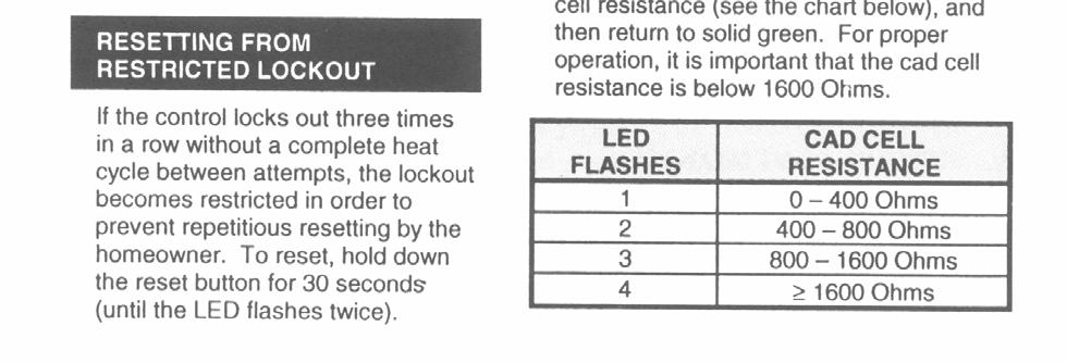
27 SECTION V FUEL OIL BURNER TO THE SERVICEMAN: Before you begin to service the burner take time to work through the following simple checklist. Also instruct the homeowner to follow this checklist before calling a serviceman. It could save you a service call. Be sure there is oil in the tank and all the valves are open. Be sure the thermostat is set above the room temperature. Be sure the furnace has power to it. Be sure the furnace is full of water Reset the Safety Switch on the Burner Primary Control Make sure the blower housing and the fan are clear of any lint or dirt. If all the above conditions check out fine and the burner runs, but no flame is observed, the fuel unit may be air bound. Follow the instructions on venting the fuel unit. Page 19


28 5-1 BECKETT FUEL OIL BURNER Page 20
29 Page 21
30 Page 22
31 Page 23
32 Page 24
33 Page 25

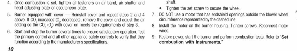
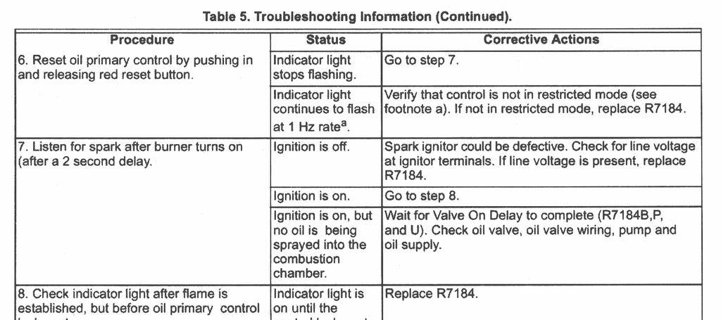
34 Reference # Description 1 Burner housing assembly 2 Air Band 3 Air Shutter 4 Escutcheon Plate 5 Hole Plug 6 Air Guide 7 Low Firing Rate Baffle 8 Pump 9 Valve Cordset 10 Solenoid Valve Kit 11 Pump Elbow 12 Connector Tube Assembly Reference # Description 13 Blower Motor 14 Blower Wheel 15 Coupling 16 Primary Control 17 Electrical Box 18 Igniter 19 Igniter Gasket Kit 20 Cad Cell Detector 21 Flange 22 Air Tube Combination 23 Heat Shield Kit 24 Electrode Kit 25 Splined Nut Page 26
35 Page 27
36 Page 28
37 Page 29
INSTALLATION AND OPERATING INSTRUCTIONS FOR THE HARDY OUTSIDE WOOD BURNING HEATER. Model H25
 INSTALLATION AND OPERATING INSTRUCTIONS FOR THE HARDY OUTSIDE WOOD BURNING HEATER Model H25 HARDY MANUFACTURING COMPANY, INC. 12345 ROAD 505 PHILADELPHIA, MS 39350 PHONE: (601) 656-5866 FAX: (601) 656-4559
INSTALLATION AND OPERATING INSTRUCTIONS FOR THE HARDY OUTSIDE WOOD BURNING HEATER. Model KBP270
 INSTALLATION AND OPERATING INSTRUCTIONS FOR THE HARDY OUTSIDE WOOD BURNING HEATER Model KBP270 HARDY MANUFACTURING COMPANY, INC. 12345 ROAD 505 PHILADELPHIA, MS 39350 PHONE: (601) 656-5866 FAX: (601) 656-4559
OPERATING INSTRUCTIONS MANUAL (Please retain for future reference) FVO-200 INDIRECT FIRED SPACE HEATERS
 FVO-200 INDIRECT FIRED SPACE HEATERS") OPERATING INSTRUCTIONS MANUAL (Please retain for future reference) For FVO-200 INDIRECT FIRED SPACE HEATERS CERTIFIED FOR USE IN CANADA AND U.S.A. As per CSA B140.8 Portable Oil Fired Heaters / CSA B140.02003
OPERATING INSTRUCTIONS MANUAL (Please retain for future reference) For FVO-200 INDIRECT FIRED SPACE HEATERS CERTIFIED FOR USE IN CANADA AND U.S.A. As per CSA B140.8 Portable Oil Fired Heaters / CSA B140.02003
OPERATING INSTRUCTIONS MANUAL (Please retain for future reference) FVO-400 INDIRECT FIRED SPACE HEATERS
 FVO-400 INDIRECT FIRED SPACE HEATERS") OPERATING INSTRUCTIONS MANUAL (Please retain for future reference) For FVO-400 INDIRECT FIRED SPACE HEATERS CERTIFIED FOR USE IN CANADA AND U.S.A. As per CSA B140.8 Portable Oil Fired Heaters / CSA B140.02003
OPERATING INSTRUCTIONS MANUAL (Please retain for future reference) For FVO-400 INDIRECT FIRED SPACE HEATERS CERTIFIED FOR USE IN CANADA AND U.S.A. As per CSA B140.8 Portable Oil Fired Heaters / CSA B140.02003
Integrated Ventilation System
 Integrated Ventilation System For use with models: IVS1, IVSR1, IVS2, IVSR2 Installation Instructions Part No. 65278 Rev. K Table of Contents Important Safety Instructions... 1 Important Information About
Columbia Boiler Company
 EMG Series Boilers Available in Natural Gas & Propane Rev 12012 Columbia Boiler Company PO Box 1070 Pottstown, PA 19464 Tel (610) 473-8457 Fax (610) 367-6800 Website www.columbiaboiler.com Email cbcsales@ptd.net
OPERATING INSTRUCTIONS MANUAL (Please retain for future reference) FVN/P-400 INDIRECT FIRED SPACE HEATERS
 FVN/P-400 INDIRECT FIRED SPACE HEATERS") OPERATING INSTRUCTIONS MANUAL (Please retain for future reference) For FVN/P-400 INDIRECT FIRED SPACE HEATERS CERTIFIED FOR USE IN CANADA AND U.S.A. As per Standard ANSI Z83.7/CSA 21.4 2000 Gas Fired Construction
OPERATING INSTRUCTIONS MANUAL (Please retain for future reference) For FVN/P-400 INDIRECT FIRED SPACE HEATERS CERTIFIED FOR USE IN CANADA AND U.S.A. As per Standard ANSI Z83.7/CSA 21.4 2000 Gas Fired Construction
Internet Version for Reference Only INDUCED DRAFT COMMERCIAL WATER HEATERS SUPPLEMENT INSTRUCTIONS TO PART #
 INDUCED DRAFT COMMERCIAL WATER HEATERS SUPPLEMENT INSTRUCTIONS TO PART #238-39387-00 THIS INSTRUCTION SUPPLEMENT IS ONLY INTENDED TO GIVE INSTALLATION INSTRUCTIONS AND INFORMATION RELATED TO THE INDUCED
DOMESTIC WATER HEATER OIL FIRED
 DOMESTIC WATER HEATER OIL FIRED Models : CMO32-II CMO32-II-R CMO50-II CMO32-II & CMO32-II-R INSTALLER / SERVICE TECHNICIAN: USE THE INFORMATION IN THIS MANUAL FOR THE INSTALLATION AND SERVICING OF THE
B.C.S. Shop Heaters 26, 30 & 36 (36 shown)
") BIOMASS COMBUSTION SYSTEMS, INC. 67 MILLBROOK ST., SUITE 502 WORCESTER, MA 01606 508-798-5970 - FAX 508-798-5971 B.C.S. Shop Heaters 26, 30 & 36 (36 shown) INSTALLATION MANUAL HAND FIRED SYSTEMS 8-09 Biomass
BIOMASS COMBUSTION SYSTEMS, INC. 67 MILLBROOK ST., SUITE 502 WORCESTER, MA 01606 508-798-5970 - FAX 508-798-5971 B.C.S. Shop Heaters 26, 30 & 36 (36 shown) INSTALLATION MANUAL HAND FIRED SYSTEMS 8-09 Biomass
GENERAL BASIC INSTALLATION INSTRUCTIONS DIRECT FIRED HOT WATER BOILERS PARKER BOILER CO.
 GENERAL BASIC INSTALLATION INSTRUCTIONS DIRECT FIRED HOT WATER BOILERS PARKER BOILER CO. GBI 201-5 3C For a proper installation and in order to receive the best in operating life and efficiency from your
10.1 Troubleshooting Condition Table
 10.1 Troubleshooting Condition Table Behavior 01. The furnace does not operate when you set the wall thermostat to a high temperature. Component 1. Wall T-Stat (See Section 10.3) 2. Blower/Fan Limit (See
OPERATING INSTRUCTIONS MANUAL (Please retain for future reference) FVN/P-400 INDIRECT FIRED SPACE HEATERS
 FVN/P-400 INDIRECT FIRED SPACE HEATERS") OPERATING INSTRUCTIONS MANUAL (Please retain for future reference) For FVN/P-400 INDIRECT FIRED SPACE HEATERS CERTIFIED FOR USE IN CANADA AND U.S.A. As per Standard ANSI Z83.7/CSA 21.4 2000 Gas Fired Construction
OPERATING INSTRUCTIONS MANUAL (Please retain for future reference) For FVN/P-400 INDIRECT FIRED SPACE HEATERS CERTIFIED FOR USE IN CANADA AND U.S.A. As per Standard ANSI Z83.7/CSA 21.4 2000 Gas Fired Construction
Oil Furnace USER S INFORMATION MANUAL FOR THE OPERATION AND MAINTENANCE OF YOUR NEW OIL-FIRED FURNACE
 Oil Furnace USER S INFORMATION MANUAL FOR THE OPERATION AND MAINTENANCE OF YOUR NEW OIL-FIRED FURNACE MODEL PO8LAA LOW-BOY NOTE TO INSTALLER: THIS MANUAL MUST BE LEFT WITH THE EQUIPMENT USER. MODEL PO8UAA
THC 85N / 175N INDUSTRIAL / COMMERCIAL SPACE HEATER
 THC 85N / 175N INDUSTRIAL / COMMERCIAL SPACE HEATER Certified to / Certifié à CGA 2.14 M2000 Conforms to / Conforme à ANSI std Z83.7 2000 Suitable for indoor or outdoor installation / Unvented / Unattended
CMO32 CMO50 DOMESTIC WATER HEATER OIL-FIRED. Models: CMO32 CMO50
 DOMESTIC WATER HEATER OIL-FIRED Models: CMO32 CMO50 DNS-1102 Rev. A DNS-0413 Rev. A CMO32 CMO50 INSTALLER / SERVICE TECHNICIAN: USE THE INFORMATION IN THIS MANUAL FOR THE INSTALLATION AND SERVICING OF
Downdraft Ventilation
 INSTALLATION GUIDE Downdraft Ventilation Contents Wolf Downdraft Ventilation...................... 3 Installation Considerations...................... 4 Downdraft Specifications.......................
FLAME115 INFRARED HEATER SERVICE MANUAL INDEX FIRE 115 WARNING
 FLAME115 INFRARED HEATER SERVICE MANUAL INDEX 1. CONTROLS AND COMPONENTS 2. FLAME CONTROL CYCLES 3. MAINTENANCE SCHEDULE 4. TROUBLESHOOTING GUIDE 5. REPAIR PROCEDURES 1. FAN MOTOR ASSEMBLY 2. FUEL FILTER
OPERATING INSTRUCTIONS MANUAL (Please retain for future reference) FVO-400 INDIRECT FIRED SPACE HEATERS
 FVO-400 INDIRECT FIRED SPACE HEATERS") OPERATING INSTRUCTIONS MANUAL (Please retain for future reference) For FVO-400 INDIRECT FIRED SPACE HEATERS CERTIFIED FOR USE IN CANADA AND U.S.A. As per CSA B140.8 Portable Oil Fired Heaters / CSA B140.02003
OPERATING INSTRUCTIONS MANUAL (Please retain for future reference) For FVO-400 INDIRECT FIRED SPACE HEATERS CERTIFIED FOR USE IN CANADA AND U.S.A. As per CSA B140.8 Portable Oil Fired Heaters / CSA B140.02003
Installation Instructions Remote Blowers
 Installation Instructions Remote Blowers Models: REMP3, REMP16 Suitable for use in a household cooking area. Suitable for use with solid state controls. To complete this blower, a Dacor hood assembly or
INSTALLATION GUIDE Dual Fuel Ranges
 INSTALLATION GUIDE Dual Fuel Ranges Contents Wolf Dual Fuel Ranges......................... 3 Safety Instructions............................ 4 Dual Fuel Range Specifications.................. 5 Dual Fuel
THC 85N / 175N INDUSTRIAL / COMMERCIAL SPACE HEATER
 THC 85N / 175N INDUSTRIAL / COMMERCIAL SPACE HEATER Certified to / Certifié à CGA 2.14 M2000 Conforms to / Conforme à ANSI std Z83.7 2000 Suitable for indoor or outdoor installation / Unvented / Unattended
1. GENERAL SAFETY RULES
 ID180 & ID290 Indirect-Fired Diesel/Oil Construction Heaters Sure Flame Products Lethbridge, Alberta, Canada Telephone: (403)328-5353 Fax: (403)328-9956 www.sureflame.ca July 12, 2006 Service and Maintenance
- 12 VDC. HHE M - 12 VDC.
 R OWNER S MANUAL Model Number HHE-200-09E - 12 VDC. HHE-500-09M - 12 VDC. OWNER S INFORMATION Owner s Name: Address: City: State: Zip Code: CUT HERE AND MAIL IN Telephone: E-mail Address: Motorhome Model:
DF400/DF600. Construction Heaters. Installation and Maintenance Manual
 342 N. Co. Rd. 400 East Valparaiso, IN 46383 219-464-8818 Fax 219-462-7985 www.heatwagon.com Installation and Maintenance Manual Please retain this manual for future reference. DF400/DF600 Construction
INSTALLATION INSTRUCTIONS
 INSTALLATION INSTRUCTIONS Keep these instructions with the boiler at all times. BOYERTOWN FURNACE CO. PO Box 100 BOYERTOWN, PA 19512 1-610-369-1450 www.boyertownfurnace.com 5-25-12 2 Danger Warning Caution
OPERATING INSTRUCTIONS MANUAL (Please retain for future reference) F-1500T DUAL FUEL CONSTRUCTION HEATER
 F-1500T DUAL FUEL CONSTRUCTION HEATER") OPERATING INSTRUCTIONS MANUAL (Please retain for future reference) For F-1500T DUAL FUEL CONSTRUCTION HEATER CERTIFIED FOR USE IN CANADA AND U.S.A. As per Standard ANSI Z83.7 2000/ CSA 2.14 2000 Gas Fired
OPERATING INSTRUCTIONS MANUAL (Please retain for future reference) For F-1500T DUAL FUEL CONSTRUCTION HEATER CERTIFIED FOR USE IN CANADA AND U.S.A. As per Standard ANSI Z83.7 2000/ CSA 2.14 2000 Gas Fired
Packaged Gas/Electric Units. Owner s Guide to Operating and Maintaining Your Gas/Electric Unit
 Packaged Gas/Electric Units Owner s Guide to Operating and Maintaining Your Gas/Electric Unit ELECTRICAL SHOCK HAZARD. FIRE OR EXPLOSION HAZARD Disconnect power at fuse box or service panel before performing
THC 85 / 175 INDUSTRIAL / COMMERCIAL SPACE HEATER
 THC 85 / 175 INDUSTRIAL / COMMERCIAL SPACE HEATER Certified to / Certifié à CGA 2.14 M2000 Conforms to / Conforme à ANSI std Z83.7 2000 Suitable for indoor or outdoor installation / Unvented / Unattended
INSTALLATION AND OPERATION MANUAL FOR 2 STAGE RIELLO BURNER ADDENDUM TO ( Mo 437 manual )
") INSTALLATION AND OPERATION MANUAL FOR 2 STAGE RIELLO BURNER ADDENDUM TO ( Mo 437 manual ) FOR USE WITH MODEL: OH6FX072DV4 PLEASE READ THESE INSTRUCTIONS PRIOR TO INSTALLATION, INITIAL FIRING, AND BEFORE
INSTALLATION AND OPERATION MANUAL FOR 2 STAGE RIELLO BURNER ADDENDUM TO ( Mo 437 manual ) FOR USE WITH MODEL: OH6FX072DV4 PLEASE READ THESE INSTRUCTIONS PRIOR TO INSTALLATION, INITIAL FIRING, AND BEFORE
For use with models: PGM304-1, versions M-B PGM365-1, versions M-E, M-F & M-G
 PGM-1 Cooktops For use with models: PGM304-1, versions M-B PGM365-1, versions M-E, M-F & M-G Install ation Instructions Part No. 65476 Rev. B Table of Contents Appliance Safety...1 Important Safety Instructions...2
VENTING CLEARANCES. BBT NORTH AMERICA Bosch Group. Bosch Water Heating 340 Mad River Park, Waitsfield, VT TWH-V-26 page 1 of 6 rev 01/06
 page 1 of 6 VENTING CLEARANCES The vents should not be obstructed and all joints properly fitted. Floors, ceilings and walls must be cut or framed to provide necessary clearance to vents. Metal strippings
SPECIFICATIONS MODEL IDF350-II IDF500 IDF500HS 500,000 BTU/HR 2.5O USGPH 60 B (SOLID) 140 P.S.I. MAXIMUM 35 IMP GALS. 42 US GALS.
 140 P.S.I. MAXIMUM 35 IMP GALS. 42 US GALS.") SPECIFICATIONS MODEL IDF350-II IDF500 IDF500HS MAXIMUM INPUT 350,000 BTU/HR 500,000 BTU/HR 500,000 BTU/HR NOZZLE SIZE 2.00 USGPH 45 B (SOLID) 2.5O USGPH 60 B (SOLID) 2.5O USGPH 60 B (SOLID) PUMP PRESSURE
SPECIFICATIONS MODEL IDF350-II IDF500 IDF500HS MAXIMUM INPUT 350,000 BTU/HR 500,000 BTU/HR 500,000 BTU/HR NOZZLE SIZE 2.00 USGPH 45 B (SOLID) 2.5O USGPH 60 B (SOLID) 2.5O USGPH 60 B (SOLID) PUMP PRESSURE
CINCINNATI, OH USA
 INSTRUCTION MANUAL Part No. 89731 Revised October 1997 CINCINNATI, OH 45241-4807 USA GAS SAFETY PRECAUTIONS Instructions on what to do when a user smells gas can be obtained from the local gas supplier.
POWER VENTER SYSTEM. Model: PVO-300, PVO-600
 POWER VENTER SYSTEM Model: PVO-300, PVO-600 Included is one ETL and cetl listed Power Venter to be used primarily with a single 120VAC controlled oil fired furnace, boiler, or water heater. The PVO may
OIL FURNACE USER S INFORMATION MANUAL FOR THE OPERATION AND MAINTENANCE OF YOUR NEW OIL-FIRED FURNACE
 58CLA OIL FURNACE USER S INFORMATION MANUAL FOR THE OPERATION AND MAINTENANCE OF YOUR NEW OIL-FIRED FURNACE NOTE TO INSTALLER: THIS MANUAL MUST BE LEFT WITH THE EQUIPMENT USER. WELCOME TO A NEW GENERATION
Installation. 324 Series Built-In Dishwashers U L. Viking Range, LLC 111 Front Street Greenwood, Mississippi USA (662)
") Installation Viking Range, LLC Front Street Greenwood, Mississippi 890 USA (66) 455-00 For product information, call -888-845-464 or visit the Viking Website at vikingrange.com U L C U L 4 Series Built-In
Installation Viking Range, LLC Front Street Greenwood, Mississippi 890 USA (66) 455-00 For product information, call -888-845-464 or visit the Viking Website at vikingrange.com U L C U L 4 Series Built-In
USER S INFORMATION MANUAL
 USER S INFORMATION MANUAL HOT WATER HEATING BOILERS DOMESTIC WATER HEATERS 150,000-300,000 Btu/hr MODELS EB-EWU-02 IMPORTANT INSTALLER - AFFIX INSTALLATION MANUAL ADJACENT TO THE BOILER CONSUMER - RETAIN
Installation Instructions Dual Fuel Ranges
 Installation Instructions Dual Fuel Ranges E30DF74EPS E36DF76EPS E48DF76EPS 5995447082 2 Safety IMPORTANT SAFETY INSTRUCTIONS Safety Precautions Do not attempt to install or operate your unit until you
VF/VG700 Jumbo. Construction Heater. Installation and Maintenance Manual
 342 N. Co. Rd. 400 East Valparaiso, IN 46383 888-432-8924 Fax 219-462-7985 www.heatwagon.com Installation and Maintenance Manual Please retain this manual for future reference. VF/VG700 Jumbo Construction
PARAFFIN/DIESEL HEATERS
 PARAFFIN/DIESEL HEATERS Model Nos. XR75 - XR105 - XR 155 Part Nos. 6920270-6920280 - 6920290 1200 Thank you for purchasing this CLARKE, Paraffin fired Space Heater. This range of portable heaters is designed
AHE S -12 VDC AHE S - 24 VDC
 Owner s Manual Model Numbers AHE-100-02S -12 VDC AHE-200-02S - 24 VDC OWNER S INFORMATION Owner s Name: Address: City: State: Zip Code: CUT HERE AND MAIL IN Telephone: Coach Model: Coach Date of Purchase:
PARTS MANUAL Model Numbers:
 PARTS MANUAL Model Numbers: AHE-100-03S - 12 VDC AHE-120-03X - 12 VDC AHE-130-03X - 12 VDC (SN: 03-675 TO 04-533) May 2014 Table Of Contents Heater Overview Webasto Diesel Burner...Page 5-8 Heating Zone
IMPORTANT INSTRUCTIONS READ & SAVE
 5000W Ceiling/Wall Mounted Garage Heater OWNER S MANUAL Model: PH-950N IMPORTANT INSTRUCTIONS READ & SAVE PET OWNERS WARNING: The health of some small pets including birds are extremely sensitive to the
OWNERS MANUAL MODEL DO110 & DO180 IS CERTIFIED TO: Unit Serial # Purchased From Company Address
 OWNERS MANUAL MODEL DO110 & DO180 IS CERTIFIED TO: UL 391 CAN/CSA B366.1 Unit Serial # Purchased From Company Address Name of Installer Installer Telephone # Date Installed IMPORTANT This manual must be
TABLE OF CONTENTS. Site preparation 2 Placement. 2 Chimney and stove pipe connections. 2
 TABLE OF CONTENTS SECTION TITLE PAGE 1. SITE PREPARATION AND INSTALLATION Site preparation 2 Placement. 2 Chimney and stove pipe connections. 2 Installation. 3 Water supply and return.. 3 Pressure/relief
OPERATING INSTRUCTIONS MANUAL (Please retain for future reference) F-400T DUAL FUEL CONSTRUCTION HEATER
 F-400T DUAL FUEL CONSTRUCTION HEATER") OPERATING INSTRUCTIONS MANUAL (Please retain for future reference) For F-400T DUAL FUEL CONSTRUCTION HEATER CERTIFIED FOR USE IN CANADA AND U.S.A. As per Standard ANSI Z83.7 2000/ CSA 2.14 2000 Gas Fired
OPERATING INSTRUCTIONS MANUAL (Please retain for future reference) For F-400T DUAL FUEL CONSTRUCTION HEATER CERTIFIED FOR USE IN CANADA AND U.S.A. As per Standard ANSI Z83.7 2000/ CSA 2.14 2000 Gas Fired
PVE SERIES POWER VENTER SYSTEM MANUAL
 PVE SERIES POWER VENTER SYSTEM MANUAL Contents Page I. Typical Venting System Components 2 II. System Operation 3 III. Power Venter Sizing 3,4 IV. Installation Safety Instructions 5,6 V. Installation of
100T399-SOLA SUPPLEMENT TO INSTALLATION & OPERATION MANUAL INCLUDED WITH WATER HEATER (SERIAL NUMBERS BEGINNING LK AND LATER)
") 100T399-SOLA SUPPLEMENT TO INSTALLATION & OPERATION MANUAL INCLUDED WITH WATER HEATER (SERIAL NUMBERS BEGINNING LK AND LATER) WARNING If the information in these instructions is not followed exactly, a
100T399-SOLA SUPPLEMENT TO INSTALLATION & OPERATION MANUAL INCLUDED WITH WATER HEATER (SERIAL NUMBERS BEGINNING LK AND LATER) WARNING If the information in these instructions is not followed exactly, a
Installation & Service Instructions for Jackson & Church Flexaire Packaged Furnaces SDF-125 thru SDF-400 Gas Firing
 Installation & Service Instructions for Jackson & Church Flexaire Packaged Furnaces SDF-125 thru SDF-400 Gas Firing Important: To protect the unit and avoid damage to the heat exchanger, the blower speed
GAS COOKTOP MODELS: CTG365D, CTG305D, CTG304D TO REDUCE THE RISK OF FIRE, ELECTRIC SHOCK, OR INJURY TO PERSONS, OBSERVE THE FOLLOWING
 By CNP INDUSTRIES, INC. P.O. Box 18645 Anaheim, Ca 92817 (877) 387-6721 INSTALLATION INSTRUCTIONS GAS COOKTOP MODELS: CTG365D, CTG305D, CTG304D IMPORTANT: Before beginning installation please read these
Owner s Manual Phoenix Aquadry TX 200
 4201 Lien Rd. Madison, WI 53704 Owner s Manual Phoenix Aquadry TX 200 Installation, Operation & Service Instructions Read and Save These Instructions The Phoenix Aquadry TX 200, like the TX 80, can be
CSD-1 COMMERCIAL BOILER CONTROLS
 SUPPLEMENTAL INSTALLATION AND OPERATING INSTRUCTIONS CSD- COMMERCIAL BOILER CONTROLS P/N 400043, Rev. A [/03] CSD- COMMERCIAL BOILER CONTROLS! WARNING Fire, explosion, asphyxiation and electrical shock
user manual Model #: BLZ-WVH-42
 user manual Model #: BLZ-WVH-42 ii Table of Contents Table of Contents 1 Safety Notice III-V 2 Diagrams 1-3 Hood Dimensions............ 1 Control Panel.............. 2 Clearance............... 3 3 Installation
Typical Mount Height. Combustion Chamber
 ! WARNING: This heater must be installed and serviced by trained gas installation and service personnel only! Improper installation, adjustment, alteration, service or maintenance can cause property damage,
USER S INFORMATION MANUAL (2,4)SG13B
SG13B") USER S INFORMATION MANUAL (2,4)SG13B Series Gas Heating/Electric Cooling Package Unit Congratulations......your outdoor heating/cooling package unit is a valuable piece of equipment, designed and manufactured
USER S INFORMATION MANUAL (2,4)SG13B Series Gas Heating/Electric Cooling Package Unit Congratulations......your outdoor heating/cooling package unit is a valuable piece of equipment, designed and manufactured
BETTER HOME COMFORT AND PEACE OF MIND STARTS WITH THE BEST SERVICE PLANS.
 BETTER HOME COMFORT AND PEACE OF MIND STARTS WITH THE BEST SERVICE PLANS. Value & Premier Oil Heating System Service Plans Choose the plan that s best for you and your home. WE PROMISE SERVICE PLANS THAT
ZG Shown READ ALL INSTRUCTIONS IN THIS MANUAL AND RETAIN FOR FUTURE REFERENCE WARNING
 See unit nameplate for manufacturer and address. 507258-04 7/2018 Supersedes 10/2017 ZG 036, 048, 060, 072, 074 (3, 4, 5 and 6 Tons) ZG 092, 102, 120, 150 (7-1/2, 8-1/2, 10 and 12 Tons) ROOFTOP UNITS ZG
SERVICE AND INSTALLATION MANUAL MODELS HDO(H) OIL FOR YOUR SAFETY
 OIL FOR YOUR SAFETY") Bousquet Technologies Inc. 2121, Nobel, Ste Julie, Quebec, Canada, J3E1Z9 SERVICE AND INSTALLATION MANUAL MODELS HDO(H) OIL Oil-Fired air heater for industrial and commercial use. FOR YOUR SAFETY Do not
Bousquet Technologies Inc. 2121, Nobel, Ste Julie, Quebec, Canada, J3E1Z9 SERVICE AND INSTALLATION MANUAL MODELS HDO(H) OIL Oil-Fired air heater for industrial and commercial use. FOR YOUR SAFETY Do not
Installation Guide. 15 W. Undercounter/Freestanding Nugget Ice Machine U L. Viking Range, LLC. 111 Front Street
 Installation Guide Viking Range, LLC 111 Front Street Greenwood, Mississippi 38930 USA (662) 455-1200 For product information, call 1-888-(845-4641) or visit our web site at vikingrange.com in the US or
IMPORTANT SAFETY INFORMATION! WARNING ALWAYS keep electric cords, home furnishings, drapes, clothing, papers, or other combustibles at least 3 feet (0
 Electric Fireplace Factory Model: EF-30D CONSUMER SAFETY INFORMATION Read this manual before installing and operating this appliance Failure to follow these instructions may result in electric shock, fire
OPERATING INSTRUCTIONS MANUAL (Please retain for future reference) FVN/P-400 INDIRECT FIRED SPACE HEATERS
 FVN/P-400 INDIRECT FIRED SPACE HEATERS") OPERATING INSTRUCTIONS MANUAL (Please retain for future reference) For FVN/P-400 INDIRECT FIRED SPACE HEATERS CERTIFIED FOR USE IN CANADA AND U.S.A. As per Standard ANSI Z83.7/CSA 21.4 2000 Gas Fired Construction
OPERATING INSTRUCTIONS MANUAL (Please retain for future reference) For FVN/P-400 INDIRECT FIRED SPACE HEATERS CERTIFIED FOR USE IN CANADA AND U.S.A. As per Standard ANSI Z83.7/CSA 21.4 2000 Gas Fired Construction
GENERAL BASIC INSTALLATION INSTRUCTIONS INDIRECT GAS FIRED WATER HEATERS PARKER BOILER CO.
 GENERAL BASIC INSTALLATION INSTRUCTIONS INDIRECT GAS FIRED WATER HEATERS PARKER BOILER CO. GBI 210 3C For a proper installation and in order to receive the best in operating life and efficiency from your
Installation, Operation and Service Manual
 Installation, Operation and Service Manual KLF-100 85% + EFFICIENCY OIL FIRED LOWBOY FURNACE INSTALLATIONS MUST MEET ALL LOCAL AND FEDERAL CODES THAT MAY DIFFER FROM THIS MANUAL Please read the manual
NOTE TO INSTALLER: THIS MANUAL MUST BE LEFT WITH THE EQUIPMENT USER.
 c_::_':_-_:_ r'" _" "_1 WARNING: If the information in this manual is not followed exactly, a fire or explosion may Iresult causing property damage, personal injury or [loss of life. m m m Do not store
POWER VENTER. Model: PVE Series
 POWER VENTER Model: PVE Series CONTENTS Typical Venting System Components... System Operation... Power Venter Sizing... Installation Safety Instructions... Installation of Power Venter... Connecting Power
Model Universal Oil Primary Control
 Model 70200 Universal Oil Primary Control Installation and Operating Instructions For Use By Qualified Service Technicians Only Universal Replacement for Carlin, Beckett, Honeywell and ICM Controls On-Board
USER S, MAINTENANCE and SERVICE INFORMATION MANUAL
 CONTENTS SAFETY INFORMATION................ 2 FOR YOUR SAFETY...................... 2 SYSTEM OPERATION.................. 2 THERMOSTATS.......................... 2 INTERMITTENT IGNITION DEVICE..........
ELITE SERIES Lo-Boy. AFUE - 83% Heating Input - 101,000 to 151,000 Btuh Nominal Add-on Cooling to 5 Ton. OIL FURNACES El0183b
 PRODUCT SPECIFICATIONS OIL FURNACES El083b ELITE SERIES Lo-Boy Bulletin No. 20629 February 209 Supersedes July 202 MODEL NUMBER IDENTIFICATION el O 83 bf 0/4 p 60 AFUE - 83% Heating Input - 0,000 to 5,000
Model No: Little Devil II (inc ss)
") GAS HEATER Model No: Little Devil II (inc ss) PART NO: 6926020, 6926025 (SS) OPERATION & MAINTENANCE INSTRUCTIONS LS1213 INTRODUCTION Thank you for purchasing this CLARKE Gas Heater. Before attempting
GAS HEATER Model No: Little Devil II (inc ss) PART NO: 6926020, 6926025 (SS) OPERATION & MAINTENANCE INSTRUCTIONS LS1213 INTRODUCTION Thank you for purchasing this CLARKE Gas Heater. Before attempting
OPERATING INSTRUCTIONS MANUAL (Please retain for future reference) F-1000T DUAL FUEL CONSTRUCTION HEATER
 F-1000T DUAL FUEL CONSTRUCTION HEATER") OPERATING INSTRUCTIONS MANUAL (Please retain for future reference) For F-1000T DUAL FUEL CONSTRUCTION HEATER CERTIFIED FOR USE IN CANADA AND U.S.A. As per Standard ANSI Z83.7 2000/ CSA 2.14 2000 Gas Fired
OPERATING INSTRUCTIONS MANUAL (Please retain for future reference) For F-1000T DUAL FUEL CONSTRUCTION HEATER CERTIFIED FOR USE IN CANADA AND U.S.A. As per Standard ANSI Z83.7 2000/ CSA 2.14 2000 Gas Fired
Installation Instructions
 Installation Instructions 30" ELECTRIC Downdraft Cooktop Modules selected at time of purchase IMPORTANT: Read and save these instructions. Part No. 208040 A 438589 Quick Reference Table of Contents: Pages
STS-JZ (premierschwank) POSITIVE PRESSURE SERIES GAS FIRED INFRA-RED TUBE HEATERS
 POSITIVE PRESSURE SERIES GAS FIRED INFRA-RED TUBE HEATERS") SUBMITTAL DATA (premierschwank) POSITIVE PRESSURE SERIES GAS FIRED INFRA-RED TUBE HEATERS PROJECT: ENGINEER: CONTRACTOR: DISTRIBUTOR: SCHWANK MODEL #: FUEL: APPROVED BY: DATE: APPROVAL #: 1 Submittal NOTICE:
SUBMITTAL DATA (premierschwank) POSITIVE PRESSURE SERIES GAS FIRED INFRA-RED TUBE HEATERS PROJECT: ENGINEER: CONTRACTOR: DISTRIBUTOR: SCHWANK MODEL #: FUEL: APPROVED BY: DATE: APPROVAL #: 1 Submittal NOTICE:
INSTALLATION AND OPERATION INSTRUCTIONS FOR
 INSTALLATION AND OPERATION INSTRUCTIONS FOR BI-40-DEEP-XT BI-50-DEEP-XT BI-60-DEEP-XT BI-72-DEEP-XT BI-88-DEEP-XT SAFETY INFORMATION WARNING If the information in these instructions are not followed exactly,
Heating system service plans that provide total peace of mind.
 Heating system service plans that provide total peace of mind. Value & Premier Oil Heating System Service Plans Choose the plan that s best for you and your home. The service plans you need to keep your
HVAC Equipment Access Equipment Location
 City of Lancaster- Building Department 121 East Chestnut Street, Suite 102, Lancaster, Ohio 43130-3825 (740) 687-6649, Fax (740) 681-5030 Web site: www.ci.lancaster.oh.us/dept/building HVAC Heating, Ventilating,
OPERATING INSTRUCTIONS MANUAL (Please retain for future reference) FVN/P-400 INDIRECT FIRED SPACE HEATERS
 FVN/P-400 INDIRECT FIRED SPACE HEATERS") OPERATING INSTRUCTIONS MANUAL (Please retain for future reference) For FVN/P-400 INDIRECT FIRED SPACE HEATERS CERTIFIED FOR USE IN CANADA AND U.S.A. As per Standard ANSI Z83.7/CSA 21.4 2000 Gas Fired Construction
OPERATING INSTRUCTIONS MANUAL (Please retain for future reference) For FVN/P-400 INDIRECT FIRED SPACE HEATERS CERTIFIED FOR USE IN CANADA AND U.S.A. As per Standard ANSI Z83.7/CSA 21.4 2000 Gas Fired Construction
INSTRUCTION MANUAL FOR OIL BURNER MODELS
 INSTRUCTION MANUAL FOR OIL BURNER MODELS X400 Bio B10 E90-803-001-001-03 Rev 13-1 - Contents Technical specifications Technical data... 3 Working field... 3 Dimensions... 4 Head and electrode settings...
US Filtermaxx. 200,000 BTU Waste Oil Burner
 US Filtermaxx 200,000 BTU Waste Oil Burner Assemble the Burner: Remove all the parts from the box. Locate the burner flange coupling and attach it to the front of the burner as seen in the photo below
USER'S MANUAL PGE Single Package Rooftop
 USER'S MANUAL PGE Single Package Rooftop Gas Heating/Electric Cooling Units Sizes 036-150 3 to 12-1/2 Tons NOTE TO INSTALLER: This manual should be left with the equipment owner. WARNING: If the information
12.0 cu.ft., 2 way, 4-door, R.V. refrigerator with ice maker.
 Installation Manual For 1200ACXX models: For 120XAC-IMXX models: 12.0 cu.ft., 2-way, 4-door, R.V. refrigerator. 12.0 cu.ft., 2 way, 4-door, R.V. refrigerator with ice maker. The letter X, in the model
LGB Gas fired boiler
 LGB Gas fired boiler Control Supplement LGB-5 Series 2 Propane gas CSD-1 Control System Part Number 550-110-682/0304 Please read this page first Hazard definitions To the installer... The following terms
INSTALLATION AND OPERATION INSTRUCTIONS FOR BI-DEEP UNITS
 INSTALLATION AND OPERATION INSTRUCTIONS FOR BI-DEEP UNITS BI-40-DEEP BI-50-DEEP BI-60-DEEP BI-72-DEEP BI-88-DEEP SAFETY INFORMATION WARNING If the information in these instructions are not followed exactly,
THC 85 INDUSTRIAL / COMMERCIAL SPACE HEATER
 A Division of THC 85 INDUSTRIAL / COMMERCIAL SPACE HEATER Certified to / Certifié à CGA 2.14 M2000 Conforms to / Conforme à ANSI std Z83.7 2000 Suitable for indoor or outdoor installation / Unvented /
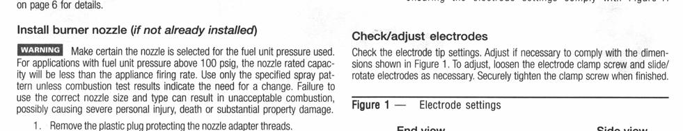
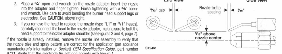
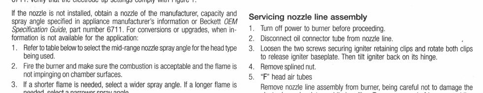
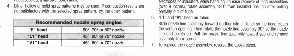
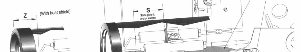
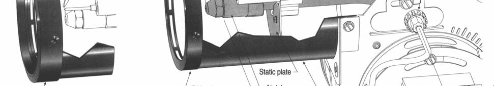
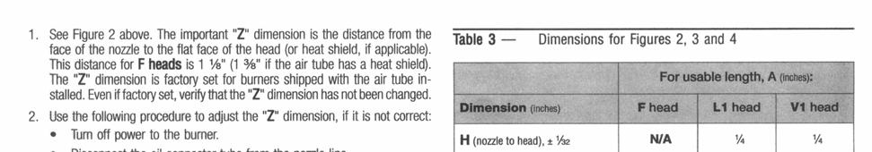
AFG AFG. Instruction Manual MODEL. Oil Burner. Types F & M air tubes Motor voltage: 120 Vac / 60 Hz. AFG burner with type F air tube
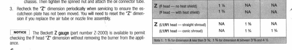
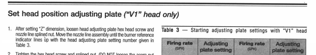
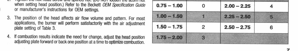
 MODEL AFG Oil Burner Instruction Manual AFG Types F & M air tubes Motor voltage: 120 Vac / 60 Hz AFG burner with type F air tube Type L1 head Type V1 head Type M air tube combinations Contents Prepare
Econo Heater. Waste Oil Fired Heater. Installation, operation and service instructions EH v Manual. Manufactured by
 Econo Heater Manufactured by Waste Oil Fired Heater Installation, operation and service instructions EH-75 120v Manual EconoHeat 5714 E. First Avenue Spokane Valley, WA 99212 800.255.1363 www.econoheat.com
THC- 355DF (Dual Fuel)
") OPERATING INSTRUCTIONS MANUAL THC- 355DF (Dual Fuel) INDUSTRIAL / COMMERCIAL DIRECTIONAL SPACE HEATER (OPERATOR MUST RETAIN FOR FUTURE REFERENCES) Certified to / Certifié à ANSI std Z83.7 2000 Suitable
OPERATING INSTRUCTIONS MANUAL THC- 355DF (Dual Fuel) INDUSTRIAL / COMMERCIAL DIRECTIONAL SPACE HEATER (OPERATOR MUST RETAIN FOR FUTURE REFERENCES) Certified to / Certifié à ANSI std Z83.7 2000 Suitable
Fig. 1 - Unit PGD4, PGS4, WPG4
 OWNER S MANUAL 14 SEER Single -Package Air Conditioner and Gas Furnace System with R -410A Refrigerant Single Phase 2 to 5 Nominal Tons Three Phase 3 to 5 Nominal Tons PGD4andPGS4SeriesE,WPG4SeriesB Fig.
Viking Installation Guide
 Viking Installation Guide Viking Range Corporation 111 Front Street Greenwood, Mississippi 38930 USA (662) 455-1200 For product information, call 1-888-VIKING1 (845-4641) or visit the Viking Web site at
Conversion Instructions Logano G234X. Gas boiler. Please read carefully before installing and servicing. Gas boiler
 Gas boiler UPON COMPLETION OF THE INSTALLATION THE INSTALLER MUST INSTRUCT THE OWNER AND OPERATOR ON THE FUNCTIONALITY AND THE PROPER OPERATION OF THE BOILER AND THE HEATING SYSTEM. INSTALLER MUST REVIEW
OPERATING & MAINTENANCE MANUAL INDUSTRIAL DIRECT FIRED DIESEL/KEROSENE HEATERS IC 25
 OPERATING & MAINTENANCE MANUAL INDUSTRIAL DIRECT FIRED DIESEL/KEROSENE HEATERS IC 25 NOT FOR DOMESTIC USE SPACE HEATING ONLY Made By: Spitwater Australia Pty Ltd 953 Metry St North Albury, NSW, Australia
Single stage operation oil burner
 Installation & Operating Manual Single stage operation oil burner WARNING NON-RETROFIT APPLICATIONS If this burner is being installed in a packaged unit (ie. burner comes with a boiler or furnace), follow
QHT Manual for: SU-2A Gas Burner
 1 QHT Manual for: SU-2A Gas Burner 50,000 BTU/H to 250,000 BTU/H The burner shall be used only with NATURAL GAS or LP GAS. Warning: If the following instructions are not followed exactly, a fire or explosion
By Authority Of THE UNITED STATES OF AMERICA Legally Binding Document
 By Authority Of THE UNITED STATES OF AMERICA Legally Binding Document By the Authority Vested By Part 5 of the United States Code 552(a) and Part 1 of the Code of Regulations 51 the attached document has
Installation Instructions
 WARNING! INSTALLATION SAFETY INSTRUCTIONS Read these instructions completely and carefully. Improper installation, adjustment, alteration, service or maintenance can cause injury or property damage. Refer
RV Products Division INSTALLATION INSTRUCTIONS FOR SERIES PACKAGE AIR CONDITIONER
 RV Products Division INSTALLATION INSTRUCTIONS FOR 46413 SERIES PACKAGE AIR CONDITIONER 1. WARNINGS IMPORTANT NOTICE These instructions are for the use of qualified individuals specially trained and experienced
PARAFFIN/DIESEL HEATER
 PARAFFIN/DIESEL HEATER MODEL NO: XR60 PART NO: 6931002 OPERATION & MAINTENANCE INSTRUCTIONS LS0813 INTRODUCTION Thank you for purchasing this CLARKE product. Before attempting to use this product, please
READ AND SAVE THESE INSTRUCTIONS
 READ AND SAVE THESE INSTRUCTIONS WARNING TO REDUCE THE RISK OF FIRE, ELECTRIC SHOCK, OR INJURY TO PERSONS, OBSERVE THE FOLLOWING: 1. Use this unit only in the manner intended by the manufacturer. If you
Fire Bowls and Fire Bowl Inserts (Automated Operation) Operating and Maintenance Instructions
 Operating and Maintenance Instructions") Table of Contents Section 1: Gas and Electric Requirements... 1 Section 2: Installation... 2 Section 3: Burner Setup and Adjustment... 8 Burner Adjustment... 9 Section 4: Maintenance... 10 Section 5: Operation...
Table of Contents Section 1: Gas and Electric Requirements... 1 Section 2: Installation... 2 Section 3: Burner Setup and Adjustment... 8 Burner Adjustment... 9 Section 4: Maintenance... 10 Section 5: Operation...