College of Technological Studies Department of Power & Refrigeration Technology. Course Contents
|
|
|
- Fay Alexander
- 5 years ago
- Views:
Transcription
1 College of Technological Studies Department of Power & Refrigeration Technology Course Contents Course Designation: Air Conditioning Control systems Course No. : Credit Hrs.: 3 Lecture Hrs.: 2 Lab Hrs.: 2 Lecturer: Eng. Raad Alsaleh Course Topics i. Background ii. Compressor Control System Reciprocating Compressors Control Capacity, safety and operation controls. Centrifugal Compressor Control Capacity, Surge, and safety control. iii. Air handling systems control Outside Air Control Minimum Outside Air, Economy Cycle Outside Air, Enthalpy Control, Static pressure Control, Air Stratification Heating Coil Control Preheat of outside or mixed air, Normal heating, Reheat cooling Coil Control Direct Expansion (DX) coils, Chilled water coils Humidity Control humidifying, Dehumidifying iv. Applications Single Zone, Multi zone and dual-duct, 3 deck Multi zone, Variable Air Volume Textbooks 1- Control Systems for Heating, Ventilating and Air Conditioning by Roger W. Haines 2- Handbook of Air Conditioning System Design, by Carrier Grading Policy 1. Attendance Homework Exam Exam Lab Final - 30
2 I. Background A. The purpose of the control system: 1. Provide automatic operation. 2. Maintain the controlled conditions closer than could be achieved by manual operation. 3. Provide maximum efficiency and economy of operation. 4. Ensure safe operation. B. Control Fundamentals: 1. The desired temperature is. 2. the actual quantity which is being controlled. Examples:,,. 3. The measures the controlled variable and convey the value to the controller. Examples: Electric Pneumatic Mechanical 4. The compares the actual quantity (Controlled variable) with the desired quantity (set point). Examples: 5. The reacts to signals received from the controller to vary a flow Examples:
3 6. The is the medium manipulated by the controlled device. Examples: 7. The mathematical relationships of control systems are usually represented by. A is the symbol which is used to indicate a summing operation, and a is the symbol for multiplication. C. Components of Control Systems: Control systems are consisting of a loop that contain: The communication signals between control system components are: D. Control Action: 1. Two-Position action: It is the simplest of automatic regulation. There is no intermediate position between the two extremes of full ON and full OFF.
4 2. Timed Two-Position action: A heater element is added to offset operation time lag. 3. Floating action: The control device will be turned off at any position if it reaches upper limit or lower limit. 4. Proportional action: Continuous action either toward OFF position or ON position, and it is of three types: a. Proportional. b. Proportional Plus Integral. c. Proportional plus derivate


5 II. Compressor Control System: A. General: The purpose of the compressor in the vapor compression cycle is to accept the low-pressure dry gas from the evaporator and raise its pressure to that of the condenser. Compressors may be of two types: 1. the general form is the piston type, or Reciprocating compressors, being adaptable in size, number of cylinders, speed and method of drive. Figure 3.1 Reciprocating compressor, (a) Suction stroke, (b) Discharge stroke


6 2. they impart energy to the gas by velocity or centrifugal force and then convert this force to pressure energy. The most common type is the Centrifugal compressors.
7 B. Reciprocating Compressors Controls: 1. Capacity Control: A refrigeration system will be designed to have a maximum duty to balance a calculated maximum load, and for much of its life may work at some lower load. Such variations require capacity reduction devices. Capacity reduction means mainly reducing the compressed by the compressor according to a set heat load. Methods of capacity control are: a) ON - OFF Control: This is generally used with residential air conditioners, where starting and stopping the compressor may be done directly by room thermostat. On a rise in room temperature the thermostat opens a Solenoid valve. The low-pressure switch closes and starts the compressor. When the Solenoid valve closes, the refrigerant is pumped out of the evaporator, opens the low-pressure switch, stopping the compressor. This type of capacity control is recommended only when the load on the system is moderately constant.


8 b) Multispeed Compressor Since the capacity of a compressor is proportional with its speed, multispeed motor may be used to regulate its capacity (Two-speed motor). This motor may be controlled by two stage thermostat and two speed magnetic starter. The added cost is the disadvantage of this control method.


9 c) Multiple Compressors: There are some applications where failure of refrigerant in equipment could result in financial loss beyond the equipment repair expense. In such cases it advisable to break the refrigeration load into multiple stages, each has its own compressor.
10 d) Loading and Unloading Cylinders: Except in very small sizes, reciprocating compressors have multistage capacity control. This is generally achieved by loading and unloading cylinders under control of a suction pressure controller, by raising the suction valve off its seat. When the load increase: (Unloading stage) Suction pressure is high Bellow shrink and Bleed port arm go up closing bleed port Pressure in the piston room increase Piston pin moves down Suction valve operates No load When load decrease or in starting: (Loading stage) Suction pressure decrease Bellow expands moving bleed port arm down opening bleed port Pressure in piston room decrease Piston pin moves up Suction valve (on load)
11
12 e) Hot Gas Bypass Control: Hot gas bypass may also be used for capacity control, for system that operates at or below minimum temperature of compressor unloading. A constant pressure expansion valve is used to maintain the evaporator pressure and temperature at constant level, regardless of load.

13 2. Safety Controls Any gas control system must include such safety controls as high or low temperature limits and high or low pressure limits a) Oil safety switch All compressors except the smallest have mechanical lubrication and will fail if the oil pressure falls because of a pump fault or oil shortage A safety cut-out is required which will stop the compressor. This takes the form of a differential pressure switch with starting time delay. A pressure gauge on the pump discharge will indicate the total pressure at that point Any detection element for true oil pump pressure must sense both suction and pump outlet pressures and transduce the difference Oil safety cut-out have pipe connections to both sides of the oil pump and two internal bellows to measure the difference.


14 Since there will be no oil pressure at the moment of starting, a time delay must be fitted to allow the oil pressure to build up This timer may be thermal or mechanical or electric. Oil safety cut-out control indicates an unsafe condition and such controls are made with hand reset switch, and normally operate an alarm to warn of the malfunction. b) Refrigerant Pressure Controls Pressure controls are used for safety protection with compressor and condenser type systems.
15 High-pressure control actuates the system if high-side pressure exceeds the preset level When the switch in the pressure control opens, the compressor is stopped. This type of safety control is required to: Prevent the compressor motor from overloading. Prevent the system from rupture. Low-pressure control is used to stop the compressor motor whenever the low-side pressure falls below a preset level Too low suction pressure mast often occurs when there is a refrigerant leak in the system. Damage to the system might result if the unit to operate under this condition, drawing moisture and air.

16 High and low pressure switches are similar in appearance. The pressure range at which the switch bellows mechanism operates determines whether it is a high or a low pressure control. All pressure switches regardless of type have a common element which is the. PRESSURE OPERATED SWITCH


17 3. Operation Control a) Water Tower Controls A reverse-acting fan pressure control in a water-cooled air conditioning system. A water tower is often used to supply cooled water to the condenser. For the system to operate efficiently, the head(high-side) pressure of the compressor must maintained within certain limits. If the head pressure becomes too low, the evaporator does not function properly. Low head pressure could be the result of too cool water being supplied to the condenser. To solve this problem, a reverse-acting fan pressure control connected to the high side pressure line of the compressor is used. When pressure is below a set limit, the fan motor will stop.


18 b) Pump-Down circuit control: A low-pressure switch is used in conjunction with a thermostat and a solenoid valve to form the pump-down circuit. In this method of control, the thermostat does not stop the compressor but de-energizes the liquid line solenoid valve to stop the supply of refrigerant to the evaporator. The compressor continues to run and pumps down the evaporator until stopped by the low-pressure switch. When the thermostat again calls for cooling, it opens the solenoid valve to let the liquid refrigerant enters the evaporator and the compressor restart again by the low-pressure switch. This method is used to ensure that the evaporator is kept clear of liquid refrigerant when the plant, is off.


19 C. Centrifugal compressors Control: Centrifugal compressors are built for heavy duty continuous operation. Centrifugal compressors are of two types: a. Open - have a shaft which projects outside the compressors housing OPEN CENTRIFUGAL MACHINE


20 b. Hermetic - have the driver built into the unit, completely isolating the refrigerant space from the atmosphere Hermetic Centrifugal Machine


21 1. Capacity Control a. Hermetic Centrifugal Temperature control is obtained by means of variable inlet guide vanes at the suction inlet of the compressor. This control reduces capacity by varying the angle at which the suction gas is directed into the eye of the impeller. At low flow the change of inlet gas direction has little effect on capacity and the control operates primarily as a suction damper. The minimum partial load capacity of the machine is based upon the amount of gas leakage thru the fully closed capacity regulating vanes.


22 When the temperature changes, the thermostat signals the control to reposition the capacity regulating vanes which changes the capacity of the system, to maintain the desired temperature. When the vanes reach the closed position and the leaving temperature continues to decrease to a predetermined minimum, the low temperature cutout switch stops the compressor. b. Open Centrifugal Capacity control on an open centrifugal compressor may be obtained with a suction damper, variable inlet guide vanes or variable speed drive. Suction damper is controlled by a thermostat to reduce the capacity of the compressor by throttling the gas suction inlet. Variable inlet guide vanes control is identical to that discussed under Hermetic centrifugal. Variable speed drives may be controlled manually when the change in loading is gradual or when a suction damper is used for automatic
23 control. Automatic speed control is used with steam, gas turbine or gas engine drives. Automatic speed control provides very economical operation, and require less input than other methods of control. COMPARATIVE PERFORMANCE, CENTRIFUGAL COMPRESSOR CAPACITY CONTROL
24 1. Safety Control a. Surge Control Surge is a characteristic of centrifugal compressors which occurs at reduced capacities. This condition is a result of the breakdown in flow which occurs in the impeller. When this happen, the impeller can no longer maintain the condenser pressure, and there occurs a momentary reversal of flow and the compressor is unable to force the gas into the condenser. The following are some conditions which may cause compressor "surge": Air in System - increases condenser pressure. Low Refrigerant Charge - lowers cooler pressure. Dirty Condenser Tubes - increases condenser pressure. Low Condenser Water Flow - may increase condenser pressure. High Entering Condensing Water Temperature increase condenser pressure Faulty Float Valve Operation - decreases cooler pressure or increases condenser pressure. Division Plate By-pass - increases condenser pressure & decreases cooler pressure. Notice all tend to increase lift by either raising condenser pressure or lowering cooler pressure. Surge is solved by lowering the condenser pressure This allow the impeller to function normally again, and gas flow returns to its normal direction. The operation is stable until the condenser pressure builds up and surge occurs again. Surging can be detected primarily by the change in sound level of the machine.


25 Surge in a centrifugal machine does not occur at partial loads if the head or lift decreases sufficiently with the load. Lift is defined as the difference between chiller suction and discharge pressures. The figure below shows a typical lift versus load diagram at different positions of the inlet guide vanes: Line (B) when the loading is such that the total lift of the compressor reduces sufficiently as the loading also reduces. Line (A) when the lift remains almost constant or decreases slightly, it can be seen that line (B) does not enter surge until load is under minimum. Line (A) enters the surge region above minimum load. IIFT-IOAD DIAGRAM, HERMETIC CENTRIFUGAL


26 To control surge occurring at partial load, a hot bypass valve between the condenser and the evaporator is used to load the compressor artificially The valve may be either manual or automatic, and controlled in sequence with the automatic suction damper or speed of the compressor or position of the inlet guide vanes So that the valve starts to open just before there is an indication of surge HOT GAS BYPASS VALVE
27 b. Condenser high pressure cutout switch It stops the compressor when the condenser pressure becomes too high due to a condenser water stoppage, excessive condenser scaling or air in the system. c. Evaporator low pressure cutout switch It stops the compressor when the evaporator pressure becomes too low due to a chilled water stoppage, excessive cooler scaling, or insufficient refrigerant charge. d. Low oil pressure cutout switch stops the compressor when the oil pressure drops below the required minimum. e. Low chilled water temperature cutout switch stops the compressor when leaving chilled water temperature drops below the minimum allowable temperature f. Chilled water flow switch stops the compressor when chilled water ceases to flow, and prevents a start-up of the compressor motor until chilled water flow is established. TYPICAL SAFETY CONTROL SYSTEM. HERMETIC MACHINE TYPICAL SAFETY CONTROL SYSTEM, OPEN MOTOR DRIVEN MACHINE


28 III. Air Handling System Control: A. Outside Air Control: Before deciding on how to control the amount of outside air it is necessary to determine how much is required by the HVAC system and why. For example, Laboratories require 100% exhaust and makeup; so chemical labs require a negative pressure to prevent exfiltration.


29 Clean rooms require that a positive internal pressure be maintained to prevent infiltration from surrounding areas. When there are no special requirements, the minimum amount of outside air required is that needed to meet the code requirements for ventilation rates. Once the criteria have been determined, one of the following methods of control can be used 1. Minimum Outside Air The simplest method of outdoor air control is to open a minimum outside air damper whenever the supply fan is running.

30 2. Economy Cycle Outside Air There many times when it is necessary to operate the cooling coil even when outdoor air temperatures are near or below the freezing mark, with outside and return dampers controlled by air temperature.
31 a. When the outside air at design winter temperature Outside air dampers are in minimum open position Return air dampers are in maximum open position b. When outside air temperature increases The mixed air thermostat (T1) gradually opens the outside air damper to maintain constant mixed air temperature. Return dampers modulate correspondingly c. When outside air temperature become moderate cooling. 100* outside air will be provided and used for d. As outside air temperature continues to increase Outdoor air high-limit thermostat(t2) cut the system back to minimum outside air, decreasing cooling load An interlock from the supply fan to close the outside air damper when the fan is off to keep out dirt and unwanted things from entering the system. 3. Enthalpy Control The outside air economy cycle control based on dry bulb temperatures is not always the most economical. That is, in very humid climates the total heat (Enthalpy) of the outside air may be greater than of the return air even though the dry bulb temperature is lower
32 Since the cooling coil must remove the total heat from the air to maintain the desired condition, it is more economical in this case to hold outside air to a minimum. 4. Static pressure Control For those spaces requiring a constant positive or negative pressure with respect to their surroundings, the outside and return air dampers will be controlled by static pressure controllers. The static pressure controller senses the difference in pressure between the controlled space and a reference location outdoors, and adjusts the dampers to maintain that pressure differential.
33 5. Air Stratification Stratification of return air and outside air streams in mixing plenums can be a serious problem. In a worst condition case, two air streams will not mix and remain separate for a long distance through filters and coils. If the outside air temperature is below freezing, the separate air stream can cause localized freezing in heating and cooling coils. Or if a good low temperature safety control is provided, the HVAC system will cycle OFF and ON.
34 The mixing plenum and its dampers should therefore be designed to promote good mixing of the air streams. Some of these methods are: a. Parallel Blade Dampers - to have the air streams meet head on b. Opposed Blade Dampers - the air streams enter opposite sides of the mixing plenum.

35 c. Dynamic mixing - propeller fan is added, set at right angles of the air streams, to provide mechanical mixing B. Heating Coil Control: Heating may be done as: Preheat of outside or mixed air Normal heating Reheat for humidity control 1. Preheat Preheating is used with large percentages of outside air to prevent freezing of downstream heating and cooling coils and to provide a usable mixed air temperature. a. The simplest control Is a two-position valve in the steam or hot water supply, with an outdoor thermostat which opens the valve whenever the outdoor temperature is below o F.
36 b. Face and bypass dampers are added at the coil and controlled by means of a downstream thermostat (T2) to provide a usable mixture temperature. The difficulty here is stratification of the two air streams.
37 c. In many cases a sufficient distance for mixing is not available. The best solution in this case is to use hot water with recirculating pump. Now there can be full flow through the coil at all times with the temperature of the water varied to suit the requirements. No air is bypassed, so there are no mixing problems. Very accurate control of air
38 temperature is possible. Notice the opposed flow arrangement, with the hot water supply entering the air leaving side of the coil. When dealing with freezing air certain precautions are necessary. For hot water, it has been shown experimentally that water velocities of ft./sec (0.9 m/s) in the coil tubes are sufficient to prevent freezing at outdoor temperatures down to -30 o F. 2. Normal Heating Normal heating refers to the coil in a single-zone, multi zone or dual-duct air system which handles all or a major portion of the system air at entering temperature of (45 o to 50 o F) or higher.

39 3. Reheat is used mainly with humidity control or individual zone control. In either case, control of steam or hot water supply valves is usually done by room thermostat.
40 C. cooling Coil Control: There are two types of cooling coils: Direct Expansion (DX) coils. Chilled water coils. 1. Direct Expansion coils: DX coils must by their nature use two-position control with its wide operating differential. This system is often used in small units. a. The room thermostat opens the solenoid valve, allowing refrigerant liquid to flow through the expansion valve to the coil. The expansion valve modulates to maintain a minimum refrigerant suction temperature. A low limit discharge thermostat (T2) keeps the supply air temperature from becoming too cold. b. Controllability can be improved by providing face and bypass dampers, but this may lead to lack of humidity control and coil icing at high bypass rates.
41 c. A different approach adds a variable back pressure valve in the refrigerant suction line, controlled by room thermostat. As the room thermostat decreases, the valve is throttled, increasing the suction temperature at the coil and decreasing the coil capacity. d. Hot gas bypass may also be used for capacity control. There are limitations on the percentage of total refrigeration flow which may be bypassed, and on pressure drops in the piping system.
42 e. Two-Stage direct expansion will often provide adequate capacity control. The stages should be made by rows of the coil rather than by sectioning the coil. In sectioning the active section may ice up forcing most of the air flow through the inactive section and reducing the coil capacity. In multi-row coil the first stage should be first row in the direction of air flow, and second stage the rest of the rows A two stage thermostat is used
43 2. Chilled Water Coils: Chilled water coils are controlled by Three-way valve (Two-position or Modulating). Recirculating pump. Recirculating pump is used in two cases: For extremely accurate temperature control. To avoid coil freezing. Parallel and Counter flow: Consider the cooling coil with air flowing through it, decreasing in temperature from 80 o to 55 o F, and with water flowing parallel or counter to the air, and increasing in temperature from 42 o to 50 o F. The heat transfer from air to water in the coil is a function of Tube wall Air and water films inside the tube wall. Total internal tube surface area. MED (Mean Equivalent Temperature Difference). where: CTD = greatest temperature difference between water and air. LTD = least temperature difference between water and air. MED = mean equivalent temperature difference. ln = natural log (log to base). If we calculate the MED for each of the two flow arrangements, we get: 1. Parallel flow: GTD = = 38 LTD = = 3 MED = 38 3 ln 38 3 = 13.3
, which is impossible with parallel flow.")
44 2. Counter flow: GTD = = 28 LTD = = 13 MED = ln = 18.7 This is an increase of nearly 1/3 in the heat transfer capacity. This should allow water temperature of 47 o F in and 57 o F out, and still get the design condition (55 o F leaving air), which is impossible with parallel flow. The higher water temperature, increases chiller efficiency and capacity. D. Humidity Control: Sometimes it may be necessary to raise or lower the humidity of the supply air in order to maintain selected humidity conditions in the air conditioned space.


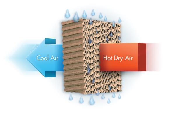
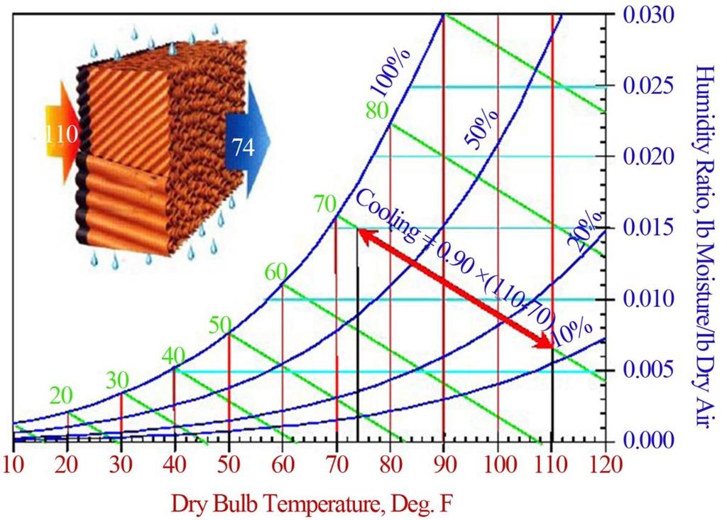
45 1. Air Washer Humidifier: Often used for its sensible cooling capability, it is then known as an evaporative loader. The cooling is accomplished by using the sensible heat of the air to evaporate water. Thus the air passing through the washer changes conditions along a constant wet bulb line, with the final state being dependent on the initial state and the saturation efficiency of the washer. The is no control of humidity.
46


47 2. Steam Humidifier: Steam humidifiers are often used because of their simplicity. A piping manifold with small orifices is provided in the air duct or plenum. The steam supply valve is controlled by space or duct humidistat. A duct high-limit humidistat must be provided to avoid condensation in the duct.


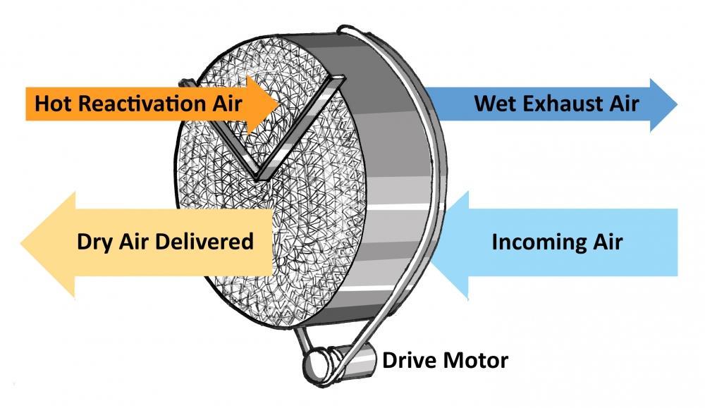
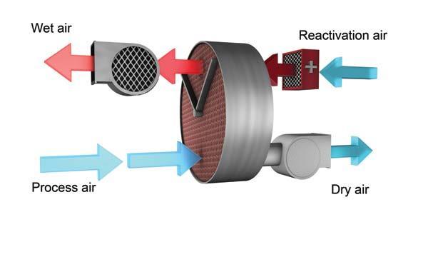
48 3. Chemical Dehumidifier: Chemical dehumidifiers use a chemical adsorbent. One form of dehumidifiers uses a wheel containing silica gel, which revolves first through the conditioned air stream, absorbing moisture, and then through a regenerative air stream of heated outside air, which dries the gel. In the process, a great deal of heat is transferred to the conditioned air, and a cooling is necessary. Space humidistat control the heating coil in the regenerative (drying) air stream, and room thermostat control the space temperature.
49


50 4. Dehumidifying by Refrigeration: Low temperature cooling coil is used to reduce humidity to low values. Special DX coils with wide fin spacing must be used.
51 A provision must be made for defrosting by: a. Hot gas b. Electric heater c. Warm air This approach has some limitations: a. Inefficient at low humidifies. b. Intermittent shutdown for defrosting. c. Reheat is necessary. Since space humidity is largely a function of coil temperature, fairly good control can be achieved through a humidistat. A room thermostat controls the cooling coil when the humidistat is satisfied. V. Applications: A. Single Zone: A space thermostat controls heating and cooling directly. If used, a humidifier is controlled by the humidistat. B. multi Zone and dual duct: The mixing dampers controlled by the zone space thermostat for each zone. If used, humidifiers are usually controlled by a return air humidistat.
52 C. Three-deck multi Zone system: The zone dampers operate with sequenced damper motor either with: 1. Mix hot supply air with bypass air when the cold deck damper is closed. 2. Mix cold supply air with bypass air when the hot deck damper is closed.
, that is reset by the thermostat.")
53 D. Variable air volume system: Motorized dampers in each zone supply duct. A related zone space thermostat controls each damper by a (flow sensor controller), that is reset by the thermostat. If used, humidifiers are controlled by a return air humidistat.
Chapter-8 Capacity Control of Refrigeration Systems
 Chapter-8 Capacity Control of Refrigeration Systems Chapter-8 Capacity Control of Refrigeration Systems ၈.၁ Compressor Control Chiller Control and Chilled Water Plant Control Refrigeration system control
RSES Technical Institute Training Manual 3 72 hours, 72 NATE CEHs, 7.2 CEUs
 Lesson 1 - Basic Heat Pump Theory (Part 1) Describe the basic operation of a heat pump. Explain the function of various heat pump controls. Interpret the wiring diagrams and performance data provided by
CHAPTER 4. HVAC DELIVERY SYSTEMS
 CHAPTER 4. HVAC DELIVERY SYSTEMS 4.1 Introduction 4.2 Centralized System versus Individual System 4.3 Heat Transfer Fluids 4.4 CAV versus VAV Systems 4.5 Common Systems for Heating and Cooling 4.6 Economizer
AIR-CONDITIONING SYSTEMS AND APPLICATIONS. Abdullah Nuhait Ph D. King Saud University
 AIR-CONDITIONING SYSTEMS AND APPLICATIONS Abdullah Nuhait Ph D. King Saud University AIR-CONDITIONING SYSTEMS Earliest air conditioning system used only for heating (winter) Provided heated air for comfort
Thomas J Kelly. Fundamentals of Refrigeration. Sr. Engineering Instructor Carrier Corporation. August 20, Page number: 1.
 Thomas J Kelly Sr. Engineering Instructor Carrier Corporation August 20, 2003 1 SESSION OBJECTIVES At the conclusion of this session you should be able to: 1. Describe the basics principles of refrigeration
HVAC Water chiller selection and optimisation of operation
 HVAC Water chiller selection and optimisation of operation Introduction Water-chiller is a broad term describing an overall package that includes an electrical control panel, refrigeration plant, water
SEQUENCE OF OPERATIONS
 SEQUENCE OF OPERATIONS DDC CONTROLLER: Controller with integral LCD readout for changing set points and monitoring unit operation. Provided with required sensors and programming. Factory programmed, mounted,
Summary Comparison of Simulation Program Features
 Summary Comparison of Simulation Program Features FEATURE DOE2.2 equest TRACE 700 HAP Public/Proprietary Public Domain Proprietary Proprietary Proprietary Simulation Method 8760 hours 8760 hours 8760 hours
THERMOSTATIC EXPANSION VALVES Part 1
 Refrigeration Service Engineers Society 1666 Rand Road Des Plaines, Illinois 60016 THERMOSTATIC EXPANSION VALVES Part 1 Revised by Loren Shuck, CMS INTRODUCTION The thermostatic expansion valve (frequently
Topic 2. ME 414/514 HVAC Systems Overview Topic 2. Equipment. Outline
 ME 414/514 HVAC Systems Overview Equipment Outline 2-1 The Complete System 2-2 The Air-Conditioning and Distribution System 2-3 Mechanical Equipment Air-handling Equipment Heating Equipment Boilers Furnaces
MECHANICAL SCIENCE Module 2 Heat Exchangers
 Department of Energy Fundamentals Handbook MECHANICAL SCIENCE Module 2 Heat Exchangers Heat Exchangers DOE-HDBK-1018/1-93 TABLE OF CONTENTS TABLE OF CONTENTS LIST OF FIGURES... ii LIST OF TABLES... iii
INTRODUCTION HVAC BASICS AND HVAC SYSTEM EFFICIENCY IMPROVEMENT SECTION O 4/19/2012
 HVAC BASICS AND HVAC SYSTEM EFFICIENCY IMPROVEMENT SECTION O INTRODUCTION HVAC systems or Heating, Ventilating and Air-Conditioning systems control the environment for people and equipment in our facilities.
Appendix 13. Categories of Cooling and Heating systems
 EcoShopping - Energy efficient & Cost competitive retrofitting solutions for Shopping buildings Co-funded by the European Commission within the 7 th Framework Programme. Grant Agreement no: 609180. 2013-09-01
APC APPLICATION NOTE #119
 #119 InRow RP-CW and InRow RP-DX Environmental Control By Henry Jespersen Abstract The primary function of the InRow RP product is to cool air from the hot aisle and deliver it to the cold aisle at the
Air-Cooling Evaporators
 Air-Cooling Evaporators Types of construction Circuit Configurations Methods of Refrigerant Feed Methods of Air Circulation Methods of Defrost Type of Construction Bare tube Finned Tube Plate-surface Bare
DEFROSTING METHODS Adapted from material originally provided by Kenneth S. Franklin, C.M., Director of Service, Hussmann Corporation
 EVAPORATOR DEFROSTING: WHEN AND WHY The refrigeration evaporator is a container that provides room for the evaporating refrigerant. The refrigerant receives heat by conduction through the walls of the
Brown University Revised August 3, 2012 Facilities Design & Construction Standards SECTION AIR HANDLING UNITS
 SECTION 23 70 00 AIR HANDLING UNITS PART 1. GENERAL 1.1 Section includes air-handling units to 15,000 cfm and accessories. 1.2 Related Sections 1 : A. Division 01 - Brown University Standard for Narragansett
Condensing Unit Installation and Operating Instructions
 Bulletin WCU_O&I 01 June 2003 Condensing Unit Installation and Operating Instructions WCU Air Cooled Condensing Unit Table of Contents Section 1. Section 2. Section 3. Section 4. Section 5. Section 6.
REFRIGERATION AND AIR CONDITIONING
 REFRIGERATION AND AIR CONDITIONING SECOND EDITION S.N. Sapali Professor of Mechanical Engineering College of Engineering, Pune Delhi-110092 2014 REFRIGERATION AND AIR CONDITIONING, Second Edition S.N.
MECHANICAL ENGINEERING ME.2017 FUNDAMENTAL OF REFRIGERATION AND AIR CONDITIONING. Sample Questions and Answers
 MECHANICAL ENGINEERING ME.2017 FUNDAMENTAL OF REFRIGERATION AND AIR CONDITIONING Sample Questions and Answers CHAPTER 5 EVAPORATORS 1. What is Evaporator? Classify the various types of evaporator. Evaporator
Refrigeration Systems and Accessories
 As with the Chapter Review Tests and the Final Exam, the tests your understanding of the materials underlying the learning objectives. After you ve reviewed your answers to the Chapter Review Tests, try
BRINE CIRCULATED ICE THERMAL STORAGE SYSTEM DESIGN - CASE ILLUSTRATION - Partial Ice Storage for Air Conditioning Application
 1 BRINE CIRCULATED ICE THERMAL STORAGE SYSTEM DESIGN - CASE ILLUSTRATION - Partial Ice Storage for Air Conditioning Application By: T. S. Wan Date: Oct. 7, 1995 Copy Right 1995 by T. S. Wan All rights
The Saturation process
 SOUTH METROPOLITAN TAFE WA The Saturation process Dennis Kenworthy 8/5/2016 A student study guide to measuring and interpreting the saturation process of refrigeration and air-conditioning equipment System
A. Base Bid: 1. Heating Contractor provide: a. Control sequences for HVAC systems, subsystems, and equipment.
 SECTION 23 09 93 - SEQUENCE OF OPERATIONS FOR HVAC CONTROLS PART 1 - GENERAL 1 WORK INCLUDES A. Base Bid: Heating Contractor provide: Control sequences for HVAC systems, subsystems, and equipment. B. Alternate
BASE LEVEL AUDIT REQUIREMENTS REFRIGERATION SYSTEMS 1. SITE DATA COLLECTION. Business Name. Site physical address (Street, Suburb, City)
") BASE LEVEL AUDIT REQUIREMENTS REFRIGERATION SYSTEMS 1. SITE DATA COLLECTION Business Name Site physical address (Street, Suburb, City) Nature of site / business operation Electricity Supplier Power factor
BASE LEVEL AUDIT REQUIREMENTS REFRIGERATION SYSTEMS 1. SITE DATA COLLECTION Business Name Site physical address (Street, Suburb, City) Nature of site / business operation Electricity Supplier Power factor
Construction Electrical
 INDEECO offers a broad range of electrical components for temperature, safety, and power control. For most applications, the Control Option system, described in the previous section, makes it easy to specify
THERMAL ICE STORAGE: Application & Design Guide
 THERMAL ICE STORAGE: Application & Design Guide Table of Contents: 1. Introduction A. History of Thermal Energy Storage B. Operating and Cost Benefits 2. Applications A Fundamental System B. HVAC Cooling
HVAC Mandatory Provisions Part II, Page 1
 HVAC Mandatory Provisions Part II, Page 1 Mandatory Equipment Efficiency Worksheet (6.4.1.1) System Equipment Type Size Category (Tables 6.8.1A through K) Sub-Category or Rating Condition Units of Efficiency
Math. The latent heat of fusion for water is 144 BTU s Per Lb. The latent heat of vaporization for water is 970 Btu s per Lb.
 HVAC Math The latent heat of fusion for water is 144 BTU s Per Lb. The latent heat of vaporization for water is 970 Btu s per Lb. Math F. to C. Conversion = (f-32)*(5/9) C. to F. Conversion = C * 9/5 +
2. CURRICULUM. Sl. No.
 . CURRICULUM Sl. No. Code Title No. of Lecture Hours 1 RAC 001 Fundamentals of Refrigeration and Air 60 conditioning RAC 00 Psychrometry, Heat load Estimation for 70 Air conditioning and Refrigeration
Are uncontrollable humidity problems costing you a bundle?
 HOT GAS REHEAT OPTION Are uncontrollable humidity problems costing you a bundle? Why put up with humidity problems when you can have true climate control with the installation of an FHP water source heat
Heat Reclaim. Benefits,Methods, & Troubleshooting By Dave Demma, Manager Supermarket Sales, Sporlan Division - Parker Hannifin Corporation
 Form 30-217 / January 2007 Heat Reclaim Benefits,Methods, & Troubleshooting By Dave Demma, Manager Supermarket Sales, Sporlan Division - Parker Hannifin Corporation While the vapor-compression cycle has
BASIC HEAT PUMP THEORY By: Lloyd A. Mullen By: Lloyd G. Williams Service Department, York Division, Borg-Warner Corporation
 INTRODUCTION In recent years air conditioning industry technology has advanced rapidly. An important byproduct of this growth has been development of the heat pump. Altogether too much mystery has surrounded
Heat Recovery Units. Heat Recovery 1
 Heat Recovery Units Heat Recovery 1 Heat Recovery Unit Why? A heat recovery unit (HRU) can help make mechanical ventilation more cost effective by reclaiming energy from exhaust airflows. HRUs use air-to-air
SPECIFICATION GUIDE FLEXAIR. Possibility to add auxiliary heaters: Gas, Electrical Heater, Hot Water Coil Possibility to add Heat Recovery Module
 SPECIFICATION GUIDE FLEXAIR Air-cooled packaged Rooftop unit Cooling only or Heat Pump Nominal cooling capacity: 85 to 234 kw Nominal heating capacity: 83 to 226 kw Possibility to add auxiliary heaters:
Fans and Pumps I. Dr. Sam C. M. Hui Department of Mechanical Engineering The University of Hong Kong
 MEBS6008 Environmental Services II http://www.mech.hku.hk/bse/mebs6008/ Fans and Pumps I Dr. Sam C. M. Hui Department of Mechanical Engineering The University of Hong Kong E-mail: cmhui@hku.hk Sep 2012
APS Chiller Seminar. Don Brandt, CEM-AEE, BEAP-ASHRAE ASHRAE and IEEE Life Member 3/16/2017
 APS Chiller Seminar Don Brandt, CEM-AEE, BEAP-ASHRAE ASHRAE and IEEE Life Member 3/16/2017 Agenda for today Refrigeration Cycle Chiller Types and Refrigerants Compressor Styles Chilled Water Pumping Systems
CONTENTS. B. System Design and Performance Requirements
 15625 Water Chillers This document provides design standards only, and is not intended for use, in whole or in part, as a specification. Do not copy this information verbatim in specifications or in notes
Energy Management and Controls
 As with the Chapter Review Tests and the Final Exam, the tests your understanding of the materials underlying the learning objectives. After you ve reviewed your answers to the Chapter Review Tests, try
Use this Construction/HVAC Glossary to answer the questions below.
 www.garyklinka.com Page 1 of 21 Instructions: 1. Print these pages. 2. Circle the correct answers and transfer to the answer sheet on the second last page. 3. Page down to the last page for the verification
DTW Works Master Specification Version 2006 Issued 2006/08/01 Section15621 Packaged Reciprocating Water Chillers Page 1 of 5
 Issued 2006/08/01 Section15621 Packaged Reciprocating Water Chillers Page 1 of 5 PART 1 GENERAL 1.1 RELATED SECTIONS.1 Section 01330 Submittal Procedures..2 Section 01355 Waste Management and Disposal..3
Condensing Unit Installation and Operating Instructions
 Bulletin ACU_O&I 02 August 2016 Condensing Unit Installation and Operating Instructions ACU Air Cooled Condensers Table of Contents Section 1. General Information... 2 Section 2. Refrigeration Piping...
Technical Development Program. COMMERCIAL HVAC PACKAGED EQUIPMENT Split Systems PRESENTED BY: Ray Chow Sigler
 Technical Development Program COMMERCIAL HVAC PACKAGED EQUIPMENT Split Systems PRESENTED BY: Ray Chow Sigler Menu Section 1 Section 2 Section 3 Section 4 Section 5 Section 6 Section 7 Introduction System
SECTION 8 AIR SOURCE HEAT PUMPS UNIT 43 AIR SOURCE HEAT PUMPS
 SECTION 8 AIR SOURCE HEAT PUMPS UNIT 43 AIR SOURCE HEAT PUMPS UNIT OBJECTIVES After studying this unit, the reader should be able to Describe the operation of reverse-cycle refrigeration (heat pumps) Explain
Electrical. Bi-Metallic Thermal Cutouts. Linear Thermal Cutouts
 Standard Construction Control Options HEATREX offers a broad range of electrical components for temperature, safety, and power control. For most applications, the Control Option system, described in the
AC SYSTEM CONFIGURATION- CENTRAL CHILLER PLANT
 AC SYSTEM CONFIGURATION- CENTRAL CHILLER PLANT Central Chiller Plant (with Cooling Tower and Chilled Water distribution) The other AC configuration is called a Chilled Water or Larger Cooler system. It
SECTION SEQUENCE OF OPERATIONS FOR HVAC CONTROLS
 SECTION 23 09 93 SEQUENCE OF OPERATIONS FOR HVAC CONTROLS PART 1 - GENERAL 1.1 SUMMARY A. This Section includes control sequences for HVAC systems, subsystems, and equipment. B. See Division 23 Section
A/C-HEATER SYSTEM - MANUAL
 A/C-HEATER SYSTEM - MANUAL 1986 Isuzu Trooper II 1986 A/C-HEATER SYSTEM Isuzu A/C-Heater Systems - Manual P UP, Trooper II * PLEASE READ THIS FIRST * CAUTION: When discharging air conditioning system,
Appendix A. Glossary of Common Terms
 Glossary of Common Terms Glossary of Common Terms Absorption chiller A refrigeration machine using heat as the power input to generate chilled water. Adjustable speed drive A means of changing the speed
STATE UNIVERSITY OF NEW YORK COLLEGE OF TECHNOLOGY CANTON, NEW YORK
 STATE UNIVERSITY OF NEW YORK COLLEGE OF TECHNOLOGY CANTON, NEW YORK COURSE OUTLINE ACHP 254 Domestic & Commercial Heating II Prepared By: CHARLES STEAD Updated By: Michael J. Newtown, P.E. CANINO SCHOOL
COMMON WATERSIDE ECONOMIZER APPLICATIONS:
 APPLICATION MANUAL WATERSIDE ECONOMIZER TABLE OF CONTENTS Safety Approvals...1 Common Waterside Economizer Applications...1 Sequence of Operation (Single)...1 Cooling Mode...2 Heating Mode...2 Sequence
For an administrative fee of $9.97, you can get an un-locked, printable version of this book.
 The System Evaluation Manual and Chiller Evaluation Manual have been revised and combined into this new book; the Air Conditioning and Refrigeration System Evaluation Guide. For an administrative fee of
R07. Answer any FIVE Questions All Questions carry equal marks *****
 Set No: 1 III B.Tech. II Semester Supplementary Examinations, April/May 2013 REFRIGERATION AND AIR CONDITIONING (Mechanical Engineering) Time: 3 Hours Max Marks: 80 Answer any FIVE Questions All Questions
Energy-Efficiency Measures List
 Guidelines for Public Agencies Energy-Efficiency Measures List 1.0 Envelope 1.1 Reduce Heat Losses-Ceiling/roof 1.11 Additional Ceiling/Roof Insulation 1.12 Exhaust Attics 1.13 Use Light-Colored Roof Surfaces
Chilled Water system
 Chilled Water system Introduction For large installations the Condenser, Evaporator, Compressor and Expansion device can be purchased as a package unit, known as a Chiller. The usual package consists of
AE October 1965 Reformatted October Hot Gas Bypass Control Systems
 Hot Gas Bypass Control Systems AE21-1160 AE21-1160 October 1965 Reformatted October 2010 On many refrigeration and air conditioning systems, the refrigeration load will vary over a wide range. This may
product application data PERFECT HUMIDITY DEHUMIDIFICATION SYSTEM
 product application data PERFECT HUMIDITY DEHUMIDIFICATION SYSTEM 551B 581B DuraPac Plus Series Sizes 036-150 3to12 1 / 2 Tons Cancels: New PAD 551B.36.2 10/1/04 CONTENTS Page INTRODUCTION.................................
Heat pump and energy recovery systems
 SBS5311 HVACR II http://ibse.hk/sbs5311/ Heat pump and energy recovery systems Ir. Dr. Sam C. M. Hui Faculty of Science and Technology E-mail: cmhui@vtc.edu.hk Oct 2017 Contents Basic concepts Air-to-air
CENTRIFUGAL PUMPS. STATE the purposes of the following centrifugal pump components:
 Pumps DOE-HDBK-1018/1-93 CENTRIFUGAL PUMPS CENTRIFUGAL PUMPS Centrifugal pumps are the most common type of pumps found in DOE facilities. Centrifugal pumps enjoy widespread application partly due to their
SECTION SEQUENCE OF OPERATIONS FOR HVAC CONTROLS
 PART 1 - GENERAL SECTION 23 09 93 SEQUENCE OF OPERATIONS FOR HVAC CONTROLS 1.1 SUMMARY A. This Section includes control sequences for HVAC systems, subsystems, and other equipment. B. See Division 23 Section
Table of Contents. Table of Contents Introduction... Intro-1
 Table of Contents Table of Contents...1-3 Introduction... Intro-1 Chapter 1 Chapter 2 Chapter 3 Chapter 4 Chapter 5 Chapter 6 Chapter 7 Chapter 8 Chapter 9 Chapter 10 Chapter 11 Chapter 12 Air Conditioning
A Design for True Performance and Energy Savings In Refrigerated Compressed Air Dryers The Digital Scroll Dryer
 A Design for True Performance and Energy Savings In Refrigerated Compressed Air Dryers The Digital Scroll Dryer Introduction By Timothy J. Fox, P.E. Hankison, an SPX Brand Canonsburg, Pennsylvania Refrigerated
AIR CONDITIONING. Carrier Corporation 2002 Cat. No
 AIR CONDITIONING Carrier Corporation 2002 Cat. No. 020-016 1. This refresher course covers topics contained in the AIR CONDITIONING specialty section of the North American Technician Excellence (NATE)
How about Savings in Time, Money, Energy and Longer Life?
 Chapter 17: The Value of Maintaining Evaporative Cooling Equipment 97 The Value 17 of Maintaining Evaporative Cooling Equipment 1. Cooling Tower Maintenance and Upgrades... What s in it for You? How about
Vapor-Compression Refrigeration
 Vapor-Compression Refrigeration condenser D C expansion device compressor A B evaporator Types of Heat Pumps water-source heat pumps water-to-water heat pump air-source heat pumps Cooling Heating
Technical Development Program
 Technical Development Program COMMERCIAL HVAC CHILLER EQUIPMENT Water-Cooled Chillers PRESENTED BY: Omar Rojas Sales Engineer Menu Section 1 Section 2 Section 3 Section 4 Section 5 Section 6 Section 7
cussons Refrigeration Assembly Range TECHNOLOGY REFRIGERATION AND AIR CONDITIONING CUSSONS TECHNOLOGY LABORATORY RECOMMENDATION
 REFRIGERATION AND AIR CONDITIONING CUSSONS LABORATORY RECOMMENDATION Cussons Refrigeration laboratories are offered to provide teaching to a range of different skill levels. In all the laboratories teaching
HVAC-201. Syllabus. Prerequisites: HVAC-101and R-410a Safety Course (The R-410a Safety course may be completed while enrolled in HVAC201)
") HVAC-201 Syllabus Instructor: Jeremie Hedges (757) 651-1007 Contact Hours: 72 hours Prerequisites: HVAC-101and R-410a Safety Course (The R-410a Safety course may be completed while enrolled in HVAC201)
HVAC-201 Syllabus Instructor: Jeremie Hedges (757) 651-1007 Contact Hours: 72 hours Prerequisites: HVAC-101and R-410a Safety Course (The R-410a Safety course may be completed while enrolled in HVAC201)
RSES Technical Institute Training Manual 2 72 hours, 72 NATE CEHs, 7.2 CEUs
 Lesson 1 - Trade Tools Explain the importance of using proper tools and test instruments. List the various types of wrenches and describe their use. Describe the proper procedures for bending, flaring,
BOOK 1 OVERVIEW RD2XRT INSTALLATION AND OPERATION MANUAL. Table of Contents ABOUT BOOK 1:
 4510 Helgesen Drive, Madison, WI, 53718 608.221.4499, 800.627.4499, Fax: 608.221.2824 support@renewaire.com www.renewaire.com RD2XRT INSTALLATION AND OPERATION MANUAL BOOK 1 OVERVIEW ABOUT BOOK 1: This
MECHANICAL SERVICES 101. Ian White
 MECHANICAL SERVICES 101 Ian White Contents 1. Ventilation 2. Heat Gains & Losses 3. Heating Ventilation Air Conditioning (HVAC) Systems What are Building Services Building Services incorporate all aspects
ME 410 MECHANICAL ENGINEERING SYSTEMS LABORATORY MASS & ENERGY BALANCES IN PSYCHROMETRIC PROCESSES EXPERIMENT 3
 ME 410 MECHANICAL ENGINEERING SYSTEMS LABORATORY MASS & ENERGY BALANCES IN PSYCHROMETRIC PROCESSES EXPERIMENT 3 1. OBJECTIVE The objective of this experiment is to observe four basic psychrometric processes
JEFFERSON COLLEGE COURSE SYLLABUS HRA 249 COMMERCIAL REFRIGERATION SYSTEMS. 5 Credit Hours. Prepared by: William Kaune November 30, 2010
 JEFFERSON COLLEGE COURSE SYLLABUS HRA 249 COMMERCIAL REFRIGERATION SYSTEMS 5 Credit Hours Prepared by: William Kaune November 30, 2010 Updated by: William Kaune April 25, 2012 Career & Technical Education
A Treatise on Liquid Subcooling
 A Treatise on Liquid Subcooling While the subject of this article is Liquid Refrigerant Subcooling, its affect on the operation of the thermostatic expansion valve (TEV), and ultimately on system performance
THERMAL ENGINEERING LABORATORY II. To train the students with principles and operation of thermal Engineering equipments.
 AIM: THERMAL ENGINEERING LABORATORY II To train the students with principles and operation of thermal Engineering equipments. OBJECTIVES: To experimentally analyze conduction, convection and radiation.
INSTALLATION INSTRUCTIONS HOT GAS BYPASS SYSTEM DESIGN MANUAL
 INSTALLATION INSTRUCTIONS HOT GAS BYPASS SYSTEM DESIGN MANUAL MODELS: WA242H WA36H NOTE: Electrical data presented in this manualsupersedes any other data for the above listed models. Bard Manufacturing
Introduction to HVAC. American Standard Inc Air Conditioning Clinic TRG-TRC018-EN
 Introduction to HVAC Agenda Psychrometrics Human Comfort Heat Transfer Refrigeration Cycle HVAC Terminology HVAC Systems Introduction to HVAC Psychrometrics 2000 TRG-TRC002-EN Properties of Air Dry-bulb
SYNOPSIS. Part-Load Control Strategies for Packaged Rooftop Units. In this issue... Bin Hour Profile Charlotte, NC
 VOLUME ONE NUMBER THREE SYNOPSIS A N H V A C N E W S L E T T E R F O R B U I L D I N G O W N E R S A N D M A N A G E R S In this issue... Part-Load Strategies Why they re important.......... 1 What Things
Institute of Aeronautical Engineering (Autonomous) Dundigal, Hyderabad B.Tech (III II SEM) MECHANICAL ENGINEERING
 Dundigal, Hyderabad B.Tech (III II SEM) MECHANICAL ENGINEERING") Institute of Aeronautical Engineering (Autonomous) Dundigal, Hyderabad- 500 043 B.Tech (III II SEM) MECHANICAL ENGINEERING REFRIGERATION AND AIR CONDITIONING Prepared by, Dr. CH V K N S N Moorthy, Professor
Institute of Aeronautical Engineering (Autonomous) Dundigal, Hyderabad- 500 043 B.Tech (III II SEM) MECHANICAL ENGINEERING REFRIGERATION AND AIR CONDITIONING Prepared by, Dr. CH V K N S N Moorthy, Professor
Technical college/ Baghdad 4th Year Week No. :- 11. The objectives of this lesson are to: Introduction:
 Refrigeration Systems Theoretical hours: 2 Practical hours: 2 Units: 6 COOLING TOWERS First 10 minutes: review the last lecture. Then explain the new lecture, solve an example. Last 10 minutes review the
DIABLO VALLEY COLLEGE CATALOG
 HEATING, VENTILATION, AIR CONDITIONING, REFRIGERATION - HVACR Open, Dean Workforce Development and Engineering Technologies Administration Building, Room 121 can earn awards at three levels of completion:
Service Step by Step Trouble-Shooting Check-List
 WARNING: Only Data Aire trained technician or experience technicians should be working on Data Aire Equipment. Protect yourself at all times and work safe. Date: Dates at the job site: From: to Job#: Serial#:
Alfa Laval Wet Surface Air Coolers (WSAC ) FAQs
 FAQs") Alfa Laval Wet Surface Air Coolers (WSAC ) FAQs Q: How is the WSAC a closed-loop cooling system? A: The WSAC is a closed-loop cooling system because the process loop being cooled is inside the tube bundles
Alfa Laval Wet Surface Air Coolers (WSAC ) FAQs Q: How is the WSAC a closed-loop cooling system? A: The WSAC is a closed-loop cooling system because the process loop being cooled is inside the tube bundles
Method to test HVAC equipment at part load conditions
 IPLV Method to test HVAC equipment at part load conditions For water cooled chillers: 100% load ( % hrs) + 75% ( Hrs ) + 50% ( Hrs ) + 25% ( Hrs ) = IPLV value Manufacturer can favor this number by tweaking
PowerPoint Presentation by: Associated Technical Authors. Publisher The Goodheart-Willcox Company, Inc. Tinley Park, Illinois
 Althouse Turnquist Bracciano PowerPoint Presentation by: Associated Technical Authors Publisher The Goodheart-Willcox Company, Inc. Tinley Park, Illinois Chapter 5 Explain the purpose and operation of
H3/V3 Series Horizontal and Vertical Indoor Air Handling Units. Engineering Catalog
 H3/V3 Series Horizontal and Vertical Indoor Air Handling Units Engineering Catalog Table of Contents AAON H3/V3 Series Features and Options Introduction... 6 H3/V3 Base Model Description... 7 Unit Size...
12 In Row. Installation Manual. MISSION CRITICAL Air Conditioning Systems. ClimateWorx International Inc.
 MISSION CRITICAL Air Conditioning Systems 12 In Row Installation Manual ClimateWorx International Inc. 14 Chelsea Lane, Brampton, Ontario, Canada L6T 3Y4 2 Table of Contents Table of Contents... 3 Site
INTRODUCTION. Special Applications of Package Air Conditioners. Instant Cooling Requirement in Wedding Ceremonies
 Pakistan s Largest Manufacturers of Air-Conditioners PACKAGE TYPE UNIT FOR MOBILE APPLICATIONS Provides Turnkey Projects Conceptual Planning to Commissioning of HVACR Projects THE LARGEST MANUFACTURER
ASE 7 - HVAC. Module 2 AC Compressors
 ASE 7 - HVAC Module 2 Acknowledgements General Motors, the IAGMASEP Association Board of Directors, and Raytheon Professional Services, GM's training partner for GM's Service Technical College wish to
Technical Development Program
 Technical Development Program PRESENTED BY: James Parker Insert your logo here AIR HANDLERS Coils: Direct Expansion Chilled Water and Heating Menu Section 1 Introduction Section 2 Typical Coil Applications
Advance Release September 2009
 Vertical Air Cooled DSV Series R 410A Model DSV096 DSV120 DSV144 DSV180 Nominal Cooling (Tons) 8 10 12 15 Refrigerant R 410A R 410A R 410A R 410A Cooling Performance Gross Cooling Capacity(Btu/h) 95,000*
WMHP Series R410a Heat Pump INSTALLATION INSTRUCTIONS
 WMHP Series R410a Heat Pump INSTALLATION INSTRUCTIONS **WARNING TO INSTALLER, SERVICE PERSONNEL AND OWNER** Altering the product or replacing parts with non authorized factory parts voids all warranty
terminal units only provide sensible cooling, a separate dehumidification system is usually needed.
 providing insights for today s hvac system designer Engineers Newsletter volume 44 3 Dual-Temperature Chiller Plants This Engineers Newsletter describes several dual-temperature configurations that can
C. Samples for Initial Selection: For units with factory-applied color finishes.
 SECTION 238126- SPLIT-SYSTEM AIR-CONDITIONERS PART 1- GENERAL 1.1 RELATED DOCUMENTS Drawings and general provisions of the Contract, including General and Supplementary Conditions and Division 01 Specification
CTI Sponsored Educational Program
 Presented By: Kent Martens SPX Cooling Technologies, Inc. Slide No.: 1 CTI Mission Statement To advocate and promote the use of environmentally responsible Evaporative Heat Transfer Systems (EHTS) for
: REFRIGERATION & AIR CONDITIONING COURSE CODE : 6023 COURSE CATEGORY : A PERIODS/ WEEK : 6 PERIODS/ SEMESTER : 90 CREDIT : 6 TIME SCHEDULE
 COURSE TITLE : REFRIGERATION & AIR CONDITIONING COURSE CODE : 6023 COURSE CATEGORY : A PERIODS/ WEEK : 6 PERIODS/ SEMESTER : 90 CREDIT : 6 TIME SCHEDULE MODULE TOPIC PERIODS 1 Introduction. Applications
2009 IECC Commercial Mechanical Requirements
 BUILDING ENERGY CODES UNIVERSITY 2009 IECC Commercial Mechanical Requirements Ken Baker PNNL-SA-66171 Learning(Objec-ves(( ( 1. Find(minimum(equipment(efficiency(requirements( and(recite(at(least(3(common(terms(for(measuring(
National Maritime Center
 National Maritime Center Providing Credentials to Mariners U.S.C.G. Merchant Marine Exam (Sample Examination) Page 1 of 26 Choose the best answer to the following Multiple Choice Questions. 1. If a condenser
Update Dedicated Heat Recovery Chiller Technology. Don Frye. Gulf South
 3/5/2018 1 Update Dedicated Heat Recovery Chiller Technology Don Frye Gulf South Good design is an intentional act Begin with the end in mind Basic Bldg Tenants IAQ (low VOC & CO 2 ) Controlled Temp &
TECHNICAL BULLETIN SELECTING A COMPRESSED AIR DRYER INTRODUCTION
 TECHNICAL BULLETIN SELECTING A COMPRESSED AIR DRYER INTRODUCTION Having an understanding of why water forms in your compressed air piping system will help you in evaluating the type of air drying system