Temperature Controllers
|
|
|
- Mark Newton
- 5 years ago
- Views:
Transcription

1 Temperature Controllers

2 Temperature Controllers No one can provide more affordable, more dependable or more accurate temperature control equipment than Thermal Care. Every temperature control unit is designed and built to meet or exceed the exacting performance standards demanded by today s manufacturing environment. Choose from several models Our complete line of temperature control equipment includes several types of controllers for use in manufacturing applications. The well-known Aquatherm RA Series, RD Series, and RE Series come in several different configurations and are possibly the best units available today at the lowest possible prices. Our popular Oiltherm RO Series hot oil temperature controllers are designed for a range of high temperature applications, and the economical Vactherm RV Series positive/negative pressure temperature controllers provide better temperature control than competitive designs when a process leak develops. Affordable, compact designs With several different configurations and model designations to choose from, it s likely that Thermal Care can match your specification with a unit directly from stock. All units are pre-wired, pre-piped and ready to install. Backed by experience You benefit from our many years of experience with process cooling and temperature control. Our experienced staff also provides a full range of customer support services to assure maximum product performance now and for years to come. When Thermal Care offers so much, why consider any other temperature controller source. The choice is obvious it s Thermal Care for quality temperature control equipment. Aquatherm controllers come with a 5-year controller warranty and lifetime exchange price of $175 (RE Series units come with 2-year warranty) Temperature Controllers from Thermal Care possibly the best available anywhere, at the best possible price


3 Control Panel STANDARD AQUATHERM CONTROLLER FEATURES 15 lights and 7 snap action switches Two easy-to-read LED digital displays showing To Process and Set Point temperatures Entire panel is sealed protecting controller against contamination from dirt or water Panel viewing angle is easy-to-read Switch between ºF/ºC temperature readout easily from front panel PID control for + 1ºF accuracy Automatic fine tuning of PID parameters Self-adjusting high/low temperature alarm deviation Power failure indicator signals brown out Automatic air purge cycle Auto vent cancel prevents venting above 150ºF Thirty-minute deviation delay stops nuisance alarms during start-up and set point change 260ºF high temperature safety State-of-the-art microprocessor control The temperature accuracy of every unit depends on its control system and Aquatherm Series temperature controllers come standard with a microprocessorbased control system designed exclusively for Thermal Care. The panel s two large digital displays make it easy to set or read system temperatures. The entire control panel is simple to understand and operate without confusing codes or useless buttons. New feature extends seal life Most everyone knows that sustained and excessive heat can reduce the life of the seals on your equipment. Aquatherm RA Series and RD Series units now come standard with Seal-Saver control software built into the microprocessor that automatically cools the process water to 90ºF. This also helps to lower hose temperatures and to prevent potential burns to the equipment operator. After activation, Aquatherm units will automatically shut down as soon as the process water reaches the pre-determined temperature level (90ºF) so your equipment can run longer with fewer seal failures. It s standard and very simple to activate with no difficult controller programming to master. Convenient controller features The unique four-plug wiring design found on Aquatherm controllers allows the entire control board to be quickly and easily replaced if necessary. To protect the controls from dirt or water, the panel overlay is sealed against contamination. A basic, less expensive, off-the-shelf 1/16 DIN plug-in type controller with on/off/vent switch comes standard on Aquatherm RE Series units. Remote control option A hand-held remote control panel is optional and includes all the lights, switches and display functions found on the machine mounted controller. The remote control panel connects using a small 8-wire phone line and will operate a unit from a distance of up to 50 feet. The remote control panel option is available for both Aquatherm RA Series and RD Series units. OPTIONAL AQUATHERM CONTROLLER FEATURES Hand-held, remote control operator panel SPI communications Audible horn From Process temperature readout Remote alarm contacts Remote on/off contacts Remote thermocouple/ RTD input
4 Aquatherm RA Series Units No other water temperature controller on the market today provides more value than the Aquatherm RA Series from Thermal Care. Units are made with the best available components like premium-quality solenoid valves, high flow pumps with leak-resistant carbon Ni-Resist seals and rugged incoloy heaters. The cast, twin tank/pump assembly is so tough it comes with an exclusive lifetime warranty. Dependable and accurate control The microprocessor-based controller is easy to operate and two digital displays assure accurate temperature settings and readouts. The sturdy cabinet takes up less than two square feet of floor space and units can be stacked when floor space is at a premium. The angled control panel is easy to read and operate. Or, an optional remote control panel allows operation from a distance of up to 50 feet. Many sizes to choose from Standard models come in a complete range of sizes from 3/4 to 7-1/2 hp, 9 to 24kw in either single or dual-zone designs. Check out our big selection of pre-engineered options that allow us to customize an Aquatherm temperature controller for your exact application. Options include: Hand-held remote control panel SPI Communications Motorized, modulating ball valve Process water air purge Closed-circuit design with heat exchanger Dual zone configuration 36kw, 48kw and 60kw units Nonferrous coatings on castings Pressure gauges EXCLUSIVE WARRANTIES Thermal Care is so certain the Aquatherm RA Series temperature control units you purchase will provide years of maintenance-free operation that we offer the following warranties at no extra cost! RA Series Units 2-year warranty on parts 2-year warranty on labor Lifetime warranty on complete twin tank/ pump volute casing assembly Lifetime warranty on pump seal 5-year warranty on controller Lifetime controller exchange price of $175 Aquatherm RA Series units are widely accepted and provide unequalled value
 comes with bronze or stainless steel impellers for turbulent flow Seal flush line assures continuous flow")
5 Removable side, top and front panels provides easy access to entire interior Bypass line protects heater and pump if process flow is shut off Long-life, low-watt density incoloy heaters (9-24kw) resist corrosion better than copper or stainless steel High capacity pump (3/4 to 7-1/2 hp) comes with bronze or stainless steel impellers for turbulent flow Seal flush line assures continuous flow across seal to remove contaminants and extend seal life (not visible) Leak-proof, cast twin tank/ pump assembly eliminates pipe fittings and flow restrictions, comes with lifetime warranty Premium quality solenoid valve assures precise temperatures Electrical components mounted in front are easily accessible and isolated from water. Adjustable water supply pressure switch prevents operation at low supply pressure Built-in sediment trap settles contaminants away from pump seal Pump seal made of leak-resistant carbon Ni-Resist, comes with lifetime warranty RA Series


6 Aquatherm RD & RE Series Units Aquatherm RD Series temperature controllers offer all the features of our full-sized unit in a smaller design Aquatherm RE Series temperature controllers comes with fewer standard features and a lower price EXCLUSIVE WARRANTIES Thermal Care builds Aquatherm RD Series and RE Series temperature control units with quality components for years of maintenancefree operation and offers the following warranties at no extra cost! RD Series Units 2-year warranty on parts 2-year warranty on labor Lifetime warranty on complete twin tank/ pump volute casing assembly Lifetime warranty on pump seal 5-year warranty on controller Lifetime controller exchange price of $175 RE Series Units 1-year warranty on parts 2-year warranty on controller Don t let the smaller size fool you. Aquatherm RD Series and RE Series units provide the same accurate and reliable temperature control as our full-sized units in a smaller cabinet. Built with rugged components for years of worry-free operation, no other controller on the market today comes with more standard features at this price. Easily accessible interior Both RD Series and RE Series units come with permanently attached, tools-free cabinet locking hardware so users can easily access interior components. The control panel opens by loosening a thumbscrew and simply flipping the hinged panel forward. Eight unique re-locking clips keep the exterior cabinet securely in place during use. Inside are high capacity pumps, leakproof, cast twin tank/pump assemblies and premium quality solenoid valves. Fits most applications Standard models are available for applications requiring between 3/4 and 3 hp. The RD Series units come with the same microprocessor-based control panel found on our RA Series units. For a less expensive alternative, our RE Series units come with an off-the-shelf 1/16 DIN plug-in type controller and on/off/vent switch. Aquatherm RE Series temperature controllers provide a less expensive control option
 Tools-free hardware allows easy access to")
7 Long-life, low-watt density incoloy heater resists corrosion better than copper or stainless steel Bypass line protects heater and pump if process flow is shut off Leak-proof, cast twin tank/ pump assembly eliminates pipe fittings and flow restrictions, comes with lifetime warranty Two pressure gauges show supply and return water pressure (optional) Tools-free hardware allows easy access to interior components Seal flush line assures continuous flow across seal to remove contaminants and extend seal life High capacity pump (3/4 to 3 hp) comes with bronze or stainless steel impellers for turbulent flow Premium quality solenoid valve assures precise temperatures Pump seal made of leak-resistant carbon Ni-Resist, comes with lifetime warranty Adjustable water supply pressure switch prevents operation at low supply pressure Four swivel casters make the unit easy to move RD & RE Series
8 Oiltherm RO Series Units Oiltherm RO Series units come in sizes from 6 to 36kw and are designed for operation to 575ºF STANDARD WARRANTY Oiltherm RO Series units are manufactured with high quality components and will provide years of accurate, on-the-job performance. Oiltherm RO Series units come with the following standard warranty. RO Series Units 1-year warranty on parts Designed and constructed for many years of dependable operation, the Oiltherm RO Series hot oil temperature controllers come standard with features like automatic oil preheat and fan cooled controls. The multistage centrifugal pump, located in the reservoir, eliminates leaks associated with positive displacement pumps. More features, more performance Oiltherm RO Series units come with important features not found on competitive units like insulated oil lines and a built-in full-week timer. By having a timer heat the process oil for several hours prior to starting production, a smaller heater can be used. Multiple 3kw low-watt density heaters provide a built-in standby. Heaters operate in two banks for better temperature control. Wide range of temperatures Compact Oiltherm RO Series units come in sturdy cabinets and are built for a wide range of high temperature applications in the 125ºF to 575ºF range. The unique design assures high velocity oil flow across heater elements for optimum heat transfer and longer heater and fluid life. A password lockout protects temperature set points and the microprocessor-based control systems allows customized settings for daily start/stop times and a temperature deviation alarm. Built-in heat exchanger Every unit comes standard with a cooling circuit where plant water is introduced into a stainless steel heat exchanger in the oil tank. The free-floating heat exchanger coil permits expansion that occurs with thermal shock. Oiltherm RO Series units are also available with a negative pressure option that reduces the possiblity of operator injury due to small leaks and allows the process oil to be drained.

9 Insulated hot oil lines and circuitry for energy efficiency and safety Convenient oil fill location allows oil to be added without removing cabinet Leak-proof centrifugal pump without rotating seals Low oil level switch prevents operation under low oil conditions Control cabinet fan protects control systems and pumps Inlet strainer on cooling water line prevents contamination Insulated oil reservoir maintains temperature and saves energy Stainless steel heat exchanger for corrosive-free operation Premium quality solenoid valve assure precise temperatures RO Series
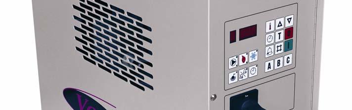
10 Vactherm RV Series Units Vactherm RV Series positive/negative pressure temperature controllers eliminate downtime caused by coolant leaks in a mold or process water circuit. The unique design of Vactherm RV Series units allows the vacuum level to be adjusted to exactly the amount necessary to stop the leak, without drawing air into the water circuit. This provides better temperature control at a lower flow rate than competitive designs. And, Vactherm RV Series units can be run as nonferrous temperature controllers even when no leak is present. Change molds fast Leave it to Thermal Care to design a unit with an automatic mold drain that permits users to change molds quickly without a hassle. Only Vactherm RV Series units come with this exclusive quick-change feature. Process water always stays isolated from cooling water thanks to a special stainless steel water circuit with automatic water makeup feature and nonferrous components in water path to assure only clean water in the mold. Extremely easy to operate Temperatures and set points are easy to read on the simple-to-operate control panel. A built-in, full-week timer lets users automatically start or stop operation and adjustable temperature deviation indicator (with audible alarm and silencer) permits users to set and customize operating parameters. Keep production moving despite mold leaks with a dependable, accurate microprocessor-based Vactherm RV Series temperature controller. Vactherm RV Series units are easy to operate and can help eliminate costly downtime STANDARD WARRANTY Vactherm RV Series units are compact, built for years of dependable operation and come with the following standard warranty. RV Series Units 1-year warranty on parts Vactherm RV Series units eliminate mold leaks while minimizing the amount of air drawn into process water

11 Stainless steel centrifugal pump protects against corrosion Inlet strainer protects against debris in water Solenoid valve automatically fills tank Dual, stainless steel, low-watt density heater elements provide long life and built-in standby Vacuum adjusting valve eliminates leak without pulling air into mold Solenoid valve regulates cooling in stainless steel heat exchanger Insulated stainless steel reservoir holds 4.5 gallons, assures temperature stability and air separation Four swivel casters make unit easy to move RV Series

12 Aquatherm Configuration Options For dual-zone applications, or if floor space is at a premium, stack RA Series units two-high without expensive racks RD Series and RE Series units can be stacked on our optional, inexpensive rack RAD Series units are perfect for dual-zone applications and house two units in one sturdy cabinet Thermal Care is a leading manufacturer of a complete line of heat transfer equipment and related services that includes: Portable Chillers Available in air and water-cooled models from 1/2 to 40 tons; every portable chiller comes with our unique, easy-to-operate microprocessor-based controller with dual, digital displays and 19 diagnostic indicators. Chiller components are easily accessible and controller comes with 5-year warranty. Pump/Reservoir Systems Every pump/reservoir is custom engineered for its application and includes a solid deck, Victaulic (grooved pipe connecting system) trim, mounted control panel and non-overloading pumps. Reservoirs are available in fiberglass, steel or stainless steel in sizes to 6000 gallons N. Lehigh Avenue Niles, Illinois Central Chillers Designed to meet most application needs in a wide variety of sizes from 20 tons. Our designs include air-cooled, water-cooled or remote condenser models. Modular, belt-drive, direct-drive and multiple circuit (with scroll or discus compressors). Cooling Towers Built of 100% nonferrous materials, our cooling towers are ruggedly designed and manufactured to exacting specifications. All towers come with a full 5-year warranty on the complete tower, including the motor. Water Treatment Equipment Our computer-controlled treatment systems incorporate all necessary facets of a cooling tower or central chiller treatment system on a single, space-saving panel. System information is displayed on a LCD screen in one of four languages. Units come with lifetime warranty. Water Filters Sand media filters, strainer filters and full flow bag filters remove heavy-duty suspended solids from both cooling tower and chilled water systems. Toll-free (888) Tel (847) Ext Fax (847) Manufacturer reserves the right to change specifications or design without notice or obligation. Thermal Care is a registered trademark of MFRI, Inc. Printed in U.S.A. Form


13 RV Series Negative Pressure Temperature Controllers Installation, Operation and Maintenance Manual
14 Table of Contents FOREWORD... 1 INSTALLATION... 1 RECEIVING INSPECTION... 1 RIGGING, HANDLING, AND LOCATING EQUIPMENT... 1 ELECTRICAL POWER... 1 Table 1 - Voltage Utilization Range... 1 START-UP... 2 CONTROLLER OPERATION... 4 Figure 1 Control Panel... 4 Table 2 Microprocessor Fault Indication... 4 OPERATING KEYS... 5 ON... 5 OFF... 5 TEMPERATURE ADJUST... 5 INCREASE... 5 DECREASE... 5 TIMER ADJUST... 5 Table 3 Calender Day Values... 5 Table 4 Timer Day Values... 6 TIMER ON/OFF... 6 DEVIATION ALARM ADJUST... 6 TANK TEMPERATURE... 6 PASSWORD ENTRY... 6 OPERATING LIGHTS... 7 PUMP... 7 HEATING... 7 COOLING... 7 LOW LEVEL... 7 DEVIATION ALARM... 7 TIMER... 7 UNIT OPERATION... 7 ADJUSTING THE VACUUM... 8 DRAINING THE MOLD... 8 PREVENTIVE MAINTENANCE... 8 ONCE A WEEK... 8 ONCE A MONTH... 8 ONCE A YEAR... 8 TROUBLESHOOTING... 9 Table 5 Troubleshooting Chart... 9 CHARTS AND DRAWINGS Figure 2 Principle of Operation Figure 3 Microprocessor Control Board (Drawing 592) Figure 4 Pump Curves (SPA-1076) Figure 5 Cooling Capacity (SPA-1079) WARRANTY... 13
15 Foreword The intent of this manual is to serve as a guide for placing your positive/negative pressure temperature control unit in service and operating and maintaining it properly. This manual is supplemented as required to accommodate any special items that may have been provided for a specific application. The written information contained in this manual, as well as various drawings, are intended to be general in nature. The schematics included in this manual are typical only. We strive to maintain an accurate record of all equipment during the course of its useful life. While every effort is made to standardize the design features of these units, the various options may make it necessary to rearrange some of the components; therefore, some of the general drawings in this manual may differ from your specific unit. Specific references to current applicable codes, ordinances, and other local laws pertaining to the use and operation of this equipment are avoided due to their ever-changing nature. There is no substitute for common sense and good operating practices when placing any mechanical equipment into operation. We encourage all personnel to familiarize themselves with this manual's contents. Failure to do so may unnecessarily prolong equipment down time. These temperature control units must be installed in a well-ventilated area, especially if open flames are present. Failure to follow these instructions could result in a hazardous condition. It is recommended that good piping practices are followed and that the information in this manual is adhered to. We cannot be held responsible for liabilities created by substandard piping methods and installation practices external to the unit. We trust your equipment will have a long and useful life. If you should have any questions, please contact our Customer Service Department specifying the serial number and model number of the unit as indicated on the nameplate. Installation Receiving Inspection Each temperature control unit is skid mounted and crated to protect it during shipping. Before accepting delivery, check the crate for visible damage. If damage is evident, it should be properly documented on the delivery receipt and the crate should be immediately removed to allow for detailed inspection of the unit. Check for broken water lines, damaged controls, or any other major component torn loose from its mounting point. Any sign of damage should be recorded and a claim filed immediately with the shipping company. In order to expedite payment for damages it is important to record and document damage. An excellent way to do this is by taking pictures. Our Customer Service Department will provide assistance with the preparation and filing of your claims, including arranging for an estimate and quotation on repairs. Rigging, Handling, and Locating Equipment The temperature control unit has a base frame on casters that has been designed to allow the unit to be easily wheeled into position. If using a forklift or overhead crane proper rigging methods must be followed to prevent damage to components. Avoid impact loading caused by sudden jerking when lifting or lowering the unit. Use pads where abrasive surface contact is anticipated. The temperature control unit is designed for indoor use. If it is necessary to store the unit in an unheated indoor area when not in use, be sure that all water is drained or that an adequate amount of antifreeze is added to prevent freeze-up of the unit. In no case should this unit be installed or stored outdoors. A primary concern when designing your unit was serviceability, therefore, the unit should be located in an accessible area. Electrical Power All wiring must comply with local codes and the National Electric Code. Minimum circuit ampacities and other unit electrical data are on the unit nameplate and are shown in the Electrical Specification section at the back of this manual. A specific electrical schematic is shipped with the unit. Measure each leg of the main power supply voltage at the main power source. Voltage must be within the voltage utilization range given in Table 1. Table 1 - Voltage Utilization Range Rated Voltage Utilization Range to to to 633 If the measured voltage on any leg is not within the specified range, notify the supplier and correct before operating the unit. Voltage imbalance must not exceed two percent. Excessive voltage imbalance between the phases of a three-phase system can cause motors to overheat and eventually fail. Voltage imbalance is determined using the following calculations: % Imbalance = (V avg V x ) x 100 / V avg V avg = (V 1 + V 2 + V 3 ) / 3 1
16 V x = phase with greatest difference from V avg For example, if the three measured voltages were 442, 460, and 454 volts, the average would be: ( ) / 3 = 452 The percentage of imbalance is then: ( ) x 100 / 452 = 2.2 % This exceeds the maximum allowable of 2%. A terminal block is provided for main power connection to the main power source. The main power source should be connected to the terminal block through an appropriate disconnect switch. A separate lug for grounding the unit is also provided in the main control panel. Electrical phase sequence must be checked at installation and prior to start-up. Operation of the temperature control unit with incorrect electrical phase sequencing will result in improper operation and can lead to mechanical damage. The phasing must be checked with a phase sequence meter prior to applying power. The proper sequence should read ABC on the meter. If the meter reads CBA, open the main power disconnect and switch two line leads on the line power terminal blocks (or the unit mounted disconnect). All components requiring electric power are wired in-phase at the factory. Do not interchange any load leads that are from the unit contactors or the motor terminals.! WARNING: It is imperative that L1-L2-L3 are connected in the A-B-C phase sequence to prevent equipment damage due to reverse rotation. Start-Up Every unit is factory set to perform in accordance with the standard operating specifications for that particular temperature control unit. Due to variables involved with different applications and different installations, minor adjustments may be required during the initial start-up to ensure proper operation. The following start-up procedure should be followed in sequence. If trouble is encountered during startup, the fault can usually be traced to one of the control or safety devices. This outline can be used as a checklist for the initial start-up and for subsequent start-ups if the unit is taken out of service for a prolonged period of time. 1. Assure the main power source is connected properly, that it matches the voltage shown on the nameplate of the unit, and that it is within the voltage utilization range given in Table 1. Electrical phase sequence must be checked at installation and prior to start-up. Operation of the temperature control unit with incorrect electrical phase sequencing will result in improper performance anc could lead to mechanical damage. The phasing must be checked with a phase sequence meter prior to applying power. The proper sequence should read ABC on the meter. If the meter reads CBA, open the main power disconnect and switch two line leads on the line power terminal blocks (or the unit mounted disconnect). All components requiring electric power are wired in-phase at the factory. Do not interchange any load leads that are from the unit contactors or the motor terminals. Once proper power connection and grounding have been confirmed, turn the main power on.! WARNING: The control panel and safeties are wired such that connecting the appropriate power source to the main terminal block energizes the entire electric circuitry of the unit. A control transformer has been factory wired to step down the incoming power to the control power. Electric power at the main disconnect should be shut off before opening access panels for repair or maintenance. The unit must be properly grounded in compliance with local and national codes.! WARNING: It is imperative that L1-L2-L3 are connected in the A-B-C phase sequence to prevent equipment damage due to reverse rotation. 2. The temperature control unit is provided with an inlet chilled water filter (shipped separately in crate). Install this in the inlet chilled water line before the line is connected to the unit. 3. Check to make sure that all process water piping connections are secure. 2
17 4. Check to make sure all cooling water piping connections are secure. Make sure sufficient cooling water flow and pressure are available and that all shut-off valves are open. 5. Turn on the control power by pressing the On button. The panel displays should now be illuminated. 6. If the display shows a decimal point in the first and last LED displays the unit is full of water and ready to operate. If the temperature control unit has never been filled or if the water level in the reservoir is insufficient, the digital displays with read FILL, the level LED will light and the unit will initiate an initial automatic fill cycle. This cycle will open the fill solenoid valve and allow the cooling source water to fill the reservoir. 9. Adjust the positive/negative flow through the mold by using the vacuum adjusting valve on top of the back panel. Start by fully closing this valve so that the injector makes a vacuum in the return line from process. At the leak, air is drawn into the circuit. The adjusting valve should be opened slowly to allow water to flow to the mold and pressurize the supply line. The leak will reappear as the pressure increases. At this point, the adjusting valve must be closed until the leak is eliminated. 10. Operate the unit for approximately 30 minutes. Check the unit for signs of leaks. Once proper flow and temperature are achieved, press the Off button. The unit is now ready to be placed into service. 7. After the reservoir is sufficiently full of water and the pump is operating, press the Temperature Adjustment key to display the current set point temperature. 8. Set the desired temperature using the Increase and Decrease buttons. When finished release all buttons. After five seconds the tank temperature is displayed and the new set point is stored. The unit will now activate the heaters and/or cooling solenoid valve to maintain set point temperture. 3
18 Controller Operation Figure 1 Control Panel Display Timer Adjust Temperature Adjust Increase Decrease Timer On/Off Cooling Light Heating 1 Light Pump Light Pump Overload Light Heating 2 Light Low Level Light Off On Tank Temperature Deviation Alarm Light Timer Activation Light ON Deviation Alarm Adjust OFF Password Entry Main Power Disconnect The temperature control unit includes a microprocessor controller designed to perform all control function from the front panel. When a key is depressed, a click will be felt. Unless instructed otherwise, only one key should be pressed at a time. Table 2 Microprocessor Fault Indication Fault Alarm Indicating LED Digital Display Indicator Tank Low Level Yes F I L L Internal Temperature Sensor Disconnected No A 2 Sensor Short Circuited (internal or external) No A 1 Actual Temperature Deviation Beyond Deviation Alarm Set Point Yes A X X. Pump Motor Overload Yes 4
19 Operating Keys On Depressing the On button will enable the control circuit. If the water level in the reservoir is below the level required to satisfy the low level sensor, the controller will initiate an initial fill sequence. During this sequence, the fill valve opens and will remain open until the proper water level is achieved. The automatic fill cycle has a four minute timer that will close the fill solenoid valve and stop the pump. This safety has been included in case there is a leak present that does not allow the reservoir to fill up. After the initial fill cycle is complete, the unit will automatically fill the tank if the level gets too low. If the fill valve remains open for more than 20 seconds, the unit will close the fill solenoid valve and shut off the pump. The display will show a "1" as the first digit followed by the tank temperature. Off Depressing the Off button will stop the pump and disable the control circuit.! I 0 CAUTION: Stopping the unit without cooling the water in the reservoir can lead to potential user injury during servicing of the unit. In order to allow the water in the reservoir to be cooled automatically during shut down, depress the Temperature Adjust button and the Password C button to initiate an automatic cool down cycle. The controller will open the cooling valve and keep it open until the temperature of the water in the reservoir is below 105 F (40 C). The automatic cool down cycle can be stopped at any time by depressing the Off button. Temperature Adjust Depressing the Temperature Adjust button will show the current set point temperature in the display. After depressing the Temperature Adjust button the set point temperature can be changed by using the Increase or Decrease buttons. Once the desired set point temperature is displayed release all buttons. After five seconds the display will return to the actual temperature and the new set point is activated. Increase Depressing the Increase button will adjust the set point, deviation alarm, and timer settings when those adjustment features are activated. Decrease Depressing the Decrease button decreases the value of the set point, deviation alarm, and timer settings when those adjustment features are activated. Timer Adjust Depressing the Timer Adjust button will activate the various timer adjustments. Setting Clock Depressing the Timer Adjust button once will show the current time value in the display. If the power to the unit has been disconnected, the clock is reset to 0000 hours (based on a 24 hour clock) and will begin keeping time from that point forward until reset. To adjust the time, use the Increase and Decrease buttons to set the current time. Once the current time is displayed release all buttons. After five seconds the display will return to the actual temperature and the new time is set. Setting Day Depressing the Timer Adjust button twice will show the current time value in the display. If the power to the unit has been disconnected, the day is reset to Monday (based on a 24 hour clock) and should be reset as required. To adjust the day, use the Increase and Decrease buttons to set the current daytime as follows. Table 3 Calender Day Values Day Display Value Monday 1000 Tuesday 2000 Wednesday 3000 Thursday 4000 Friday 5000 Saturday 6000 Sunday 7000 Once the current day is displayed release all buttons. After five seconds the display will return to the actual temperature and the new day is set. Setting Start Time Depressing the Timer Adjust button and then immediately depressing the Timer On/Off button once will reset the display to To adjust the start time, use the Increase and Decrease buttons to set the desired start time (based on a 24 hour clock). Once the start time is displayed release all buttons. After five seconds the display will return to the actual temperature and the new start time is set. Setting Stop Time Depressing the Timer Adjust button and then immediately depressing the Timer On/Off button twice will reset the display to To adjust the stop time, use the Increase and Decrease buttons to 5
20 set the desired stop time (based on a 24 hour clock). Once the stop time is displayed release all buttons. After five seconds the display will return to the actual temperature and the new stop time is set. Setting Days for Automatic Start/Stop Depressing the Timer Adjust button twice and then immediately depressing the Timer On/Off button once will reset the display to show the settings for Monday. When reviewing the settings for each day of the week, the first digit on the left of the display indicates the day of the week as follows. Table 4 Timer Day Values Day Display Value M onday 1 Tuesday 2 W ednesday 3 Thursday 4 Friday 5 S aturday 6 Sunday 7 The remaining three digits of the display indicate the activation status of that day. If these three digits display a decimal in the first and third digits, then that day is the day is scheduled for automatic start/stop. If these three digits display a decimal in the second and third digits, then that day is not scheduled for automatic start/stop. Example If Monday is scheduled for automatic start/stop the display will show 1 Example If Monda y is not scheduled for automatic start/stop the display will show 1 Timer On/Off To toggle the schedule status, press the On button once. The display will now change and indicated the change. Once the current setting is displayed, depress the Increase button to display the next day. Once all days have been programmed release all buttons. After five seconds the display will return to the actual temperature and the days for automatic start/stop are set. T Depressing the Timer On/Off button will activate or deactivate the automatic start/stop timer. If the far right hand display shows a decimal after the number displayed, then the automatic start/stop timer is activated. If no decimal is displayed the automatic start/stop timer is deactivated. Deviation Alarm Adjust Depressing the Deviation Alarm Adjust button will show the current deviation alarm set point in the display. The deviation alarm set point is the number of degrees the actual tank temperature must rise above the set point temperature before the alarm horn will activate. After depressing the Deviation Alarm Adjust the deviation alarm set point temperature can be changed by using the Increase or Decrease buttons. Once the desired deviation alarm set point is displayed release all buttons. After five seconds the display will return to the actual temperature and the new deviation alarm is set. Note: There is a time delay after initial start-up before the temperature deviation alarm becomes activate. The unit must be on with the pump running for 45 minutes before the alarm function is active. This time delay feature is designed to minimize the potential for unwanted alarms during initial startup as the unit brings the system up to operating temperature. Tank Temperature Depressing the Tank Temperature button will show the current tank temperature in the display. Password Entry A B C Depressing the Password Entry buttons will allow for secured access to the control program and will prevent unauthorized personnel from making changes. If a password has been entered, you will be required to enter the correct four letter password to make any adjustments to temperatures or timer functions. The password remains in memory even if the power is disconnected. Entering or Changing Password Depress the Off button and then immediately depress and hold the C Password Entry button for three seconds. The display will now show a C in the second display. Immediately enter a password consisting of any combination of four letters. The controller counts the number of letters entered and the display will show a 4 in the last display meaning all four password letters have been entered. Once the 4 appears release all buttons and press the Off button to store the password. Press the On button to restart the unit. The display will return to the actual temperature and the setting cannot be changed without the password. Deleting Password Depress the C and hold until the second display show C then press the Off button to delete the password. When the password has been deleted the first and last displays will show. To resume operation press the On button and the unit will 6
21 resume normal operation without password protection. Operating Lights There are eight operating lights, each located within a corresponding icon for that operational function. Pump There are two indicating lights in the Pump icon. The upper LED will be green when the pump is energized. The lower LED will be yellow when the pump motor overload has been tripped. Heating There are two indicating lights in the Heating icon. The upper LED will be green when heater 1 is energized. The lower LED will be green when heater 2 is energized. Cooling The LED in the Cooling icon will be green when the cooling solenoid valve is energized. Low Level The LED in the Low Level icon will be yellow when the water level in the reservoir is too low. Deviation Alarm The LED in the Deviation Alarm icon will be green when the Deviation Alarm is active. This LED will not be lighted if the Deviation Alarm has been turned off. Timer The LED in the Timer icon will be green when the Automatic Start/Stop Timer is active. This LED will not be lighted if the Automatic Start/Stop Timer has been turned off. Unit Operation The temperature control unit is designed to circulate water through a process and to precisely, automatically, and reliably maintain the water temperature at the selected set point temperature. The operating range of the unit is from 50 F (10 C) to 205 F (96 C). The unit is well suited or use with city water, water from chillers, cooling towers, or wells to provide the cooling water supply. The unit is a compact corrosion-proof unit with an integral stainless steel tank, stainless steel heating elements, cooling heat exchanger and an immersed stainless steel centrifugal pump without rotating seals. Water is pumped to the process through the discharge line and to the tank through the return line. The unit is an open system. The temperature in the tank is controlled by a microprocessor. The tank (process) temperature is displayed on the control panel LED's. During the heating cycle, the heating element is activated (if ordered) according to the heating requirement. During the cooling cycle, the solenoid valve opens and the cooling water is circulated through the heat exchanger until the proper temperature is reached. When the unit is connected to the power source, an LED connected to a level probe inside the tank will indicate whether the water has been filled to the correct level. The unit will automatically fill the tank to the correct level using the cooling water supply. When the unit is operating and there is too little water in the tank, the lamp lights, the pump stops and heating ceases. Once the tank is filled to the correct level, the unit will start automatically. The microprocessor controls the temperature and water level in the unit. The microprocessor includes alarms for low tank level and temperature deviation as well as a timer making automatic start/stop of the temperature controller possible. If a leak occurs in the mold or in the process, the built-in push-pull system permits stable temperature control without interrupting production. Through the use of the vacuum adjusting valve, the push-pull system makes it possible to supply pressure to the leak and vacuum from the leak back to the unit. If a leak occurs, the flow through the circuit should be arranged so that the leak is at the end of the water circuit. 7
22 Adjusting The Vacuum Adjust the positive/negative flow through the mold by using the vacuum adjusting valve on top of the back panel. Start by fully closing this valve so that the injector makes a vacuum in the return line from process. At the leak, air is drawn into the circuit. The adjusting valve should be opened slowly to allow water to flow to the mold and pressurize the supply line. The leak will reappear as the pressure increases. At this point, the adjusting valve must be closed until the leak is eliminated. Draining the Mold The temperature control unit is equipped with a specific program that can automatically cool to 105 F (40 C) before draining the mold. To initiate a mold drain sequence depress the Temperature Adjust button and then immediately depress the On button. The display will show E followed by the actual temperature in the tank. The cooling solenoid valve is energized and will remain energized unit the tank temperature drops to 105 F (40 C). When the tank temperature reached 105 F (40 C) the alarm horn will sound to signal the mold is ready for draining. Once the unit has cooled to 105 F (40 C), close the vacuum adjusting valve and remove the hose on the valve. A strong air current will automatically be sucked through the hoses and the mold. When the unit is finished draining, turn the unit off by depressing the Off button and remove the hoses. Preventive Maintenance One your positive/negative pressure temperature control unit has been placed into service, the following maintenance procedures should be adhered to as closely as possible. The importance of a properly established preventive maintenance program cannot be overemphasized. Taking the time to follow these simple procedures will result in substantially reduced downtime, reduce repair costs, and an extended useful lifetime for the unit. Any monetary costs of implementing these procedures will almost always more than pay for itself. Once a Week 1. Check all water line connections for signs of leaks. Replace or repair water lines and/or fittings as necessary. 2. Check to make sure the To Process temperature is maintained reasonably close to the Set Point temperature. If the temperature varies more than 5 F (3 C) from the set point temperature, there may be a problem with the unit. If this occurs, refer to the Troubleshooting Chart or contact our Customer Service Department. 3. Check the pump discharge pressure of the unit. If the discharge pressure starts to stray from the normal operating pressure this could be an indication that the leak in the mold has worsened or that there may be a problem with the unit. If this occurs, refer to the Troubleshooting Chart or contact our Customer Service Department. Once a Month Repeat items 1 through 3 as listed above and continue with the following. 4. With the main disconnect shut off and locked out, check the condition of electrical connections at all contactors, starters and controls. Check for loose or frayed wires. 5. Check the incoming voltage to make sure it is within 10% of the design voltage for the unit. 6. Check the amp draws to each leg of the pump and heaters to confirm that they are drawing the proper current. 7. Check the heat exchanger inlet strainer and clean debris out as necessary. Once a Year Repeat items 1 through 7 as listed above and continue with the following. 8. Carefully inspect the heat exchanger for signs of scale build-up and carefully clean and remove scale as necessary.! CAUTION: The amount of scale build-up is dependent upon the amount of cooling required for each process along with the quality of the cooling water supply. We have supplied the unit with a stainless steel heat exchanger to allow the use of strong lime scale removal chemicals (acids). We recommend you clean the heat exchanger thoroughly on a periodic basis, or after each job, to allow for the longest life and highest heat removal potential of the unit. If the heat exchanger becomes completely blocked, lime scale removal will be impossible. 8
23 Troubleshooting Table 5 Troubleshooting Chart Problem Possible Cause Remedy Main fuses blown Replace blown fuses The unit does not start after connection, tank filling, and pressing the On button Motor defective Reset tripped Contact factory Reset Motor buzzes after pressing the On button and overload trips Control circuit breaker tripped Voltage on two of the phases only Motor defective Reset Check incoming power supply, check and replace blown fuse Contact factory No water circulation, even though the pump is rotating Pump is rotating in the wrong direction Process water lines clogged Change two of the incoming power leads Clean lines Contactor defective Replace contactor The unit does not heat Thermostat defective Heating element defective Replace thermostat Replace heating element The unit does not cool Safety fuse defective Solenoid valve at Cooling Water In defective Cooling heat exchanger clogged Replace safety fuse Replace solenoid valve Clean coil The unit cooling all the time Thermostat defective Dirt in the cooling solenoid valve Thermostat defective Replace thermostat Take apart the valve, clean out, replace if required Replace thermostat Water comes out the overflow pipe Tank overfilled Dirt in the fill solenoid valve Level sensing probe dirty or defective Drain some water Take apart the valve, clean out, replace if required Clean probe, replace if required The unit does not fill the tank, level lamp is not on Level sensing probe dirty or defective Defective microprocessor Clean probe, replace if required Contact factory The unit does not fill the tank, level lamp is on Water supply not connected Defective fill solenoid valve Connect supply Replace if required 9
24 Charts and Drawings Figure 2 Principle of Operation From mold 2. To mold 3. Cooling water in 4. Cooling water out 5. Pump 6. Tank 7. Level sensor 8. Temperature sensor 9. Microprocessor control 10. Heat exchanger 11. Heating element 12. Overflow pipe 13. Solenoid valve for water filling 14. Solenoid valve for cooling 15. Connection for external sensor 16. Check valve 17. Venturi 18. Adjusting valve, vacuum 19. Solenoid valve, mold draining 10
25 Figure 3 Microprocessor Control Board (Drawing 592) 11
26 Figure 4 Pump Curves (SPA-1076) HP PUMP PRESSURE /2 HP /2 HP NEGATIVE PRESSURE 2 HP NEGATIVE PRESSURE GALLONS PER MINUTE Figure 5 Cooling Capacity (SPA-1079) BTU/H X T( F) = TANK TEMPERATURE LESS COOLING WATER TEMPERATURE 12
Hydra Negative Pressure, Closed-Loop Mold Temperature Controllers INSTRUCTION MANUAL
 Hydra Negative Pressure, Closed-Loop Mold Temperature Controllers INSTRUCTION MANUAL July 2012 IMS Company 10373 Stafford Road Chagrin Falls, OH 44023-5296 Telephone: (440) 543-1615 Fax: (440) 543-1069
Aquatherm Series Temperature Controllers. Installation, Operation and Maintenance Manual
 Aquatherm Series Temperature Controllers Installation, Operation and Maintenance Manual Table of Contents FOREWORD... 1 INSTALLATION... 1 Receiving Inspection... 1 Rigging, Handling, and Locating Equipment...
LQ AQ SQ. Air-cooled and water-cooled portable chillers
 LQ AQ SQ Air-cooled and water-cooled portable chillers Choose from a complete line of dependable Accuchiller portable chillers LQ Series AQ Series SQ Series No other manufacturer can offer you a larger
LQ AQ SQ. Air-cooled and water-cooled portable chillers
 LQ AQ SQ Air-cooled and water-cooled portable chillers Choose from a complete line of dependable Accuchiller portable chillers LQ Series AQ Series SQ Series No other manufacturer can offer you a larger
Installation, Operation and Maintenance Manual. LQ Series Portable Chillers
 Installation, Operation and Maintenance Manual LQ Series Portable Chillers Table of Contents Foreword... 1 Installation... 1 Receiving Inspection... 1 Rigging, Handling, and Locating Equipment... 1 Electrical
EQ Series Portable Chillers
 EQ Series Portable Chillers Installation, Operation and Maintenance Manual Copyright Thermal Care Inc. 2010 Table of Contents Foreword... 1 Installation... 1 Receiving Inspection... 1 Rigging, Handling,
Installation, Operation and Maintenance Manual. RQ Series. Mold Temperature Control Units 0.75 to 7.5 hp and 0 to 24 kw
 Installation, Operation and Maintenance Manual RQ Series Mold Temperature Control Units 0.75 to 7.5 hp and 0 to 24 kw Copyright 2010 Thermal Care Inc. Table of Contents Foreward... 3 Safety Guidelines...
EP1 Series Portable Chillers
 USER GUIDE UGH036-0613 www.conairgroup.com EP1 Series Portable Chillers Air-Cooled Models EP1A-01, EP1A-02, EP1A-03 Water-Cooled Models EP1W-02, EP1W-03 Remote Condenser Model EP1R-03 Thank you for purchasing
Installation, Operation and Maintenance Manual. LQ Series. Portable Chillers 7 to 40 Tons
 Installation, Operation and Maintenance Manual LQ Series Portable Chillers 7 to 40 Tons Copyright Thermal Care Inc. 2011 Page intentionally blank Table of Contents Foreword... 1 Installation... 1 Receiving
RQE Series Temperature Controllers
 RQE Series Temperature Controllers For more than 45 years, Thermal Care has manufactured industrial temperature control equipment with the best available component technologies. Our RQE Series mold temperature
Precise Temperature Control; Compact Footprint
 Precise Temperature Control; Compact Footprint The Conair EP1 Series Portable Chillers are designed for 1 to 3 ton applications. Available as air-cooled or water-cooled, with pump sizes from 1/4 to 3 Hp
30 F to 300 F Process Temperatures* 1/2 to 7.5 HP Centrifugal Pumps ( GPM) 3/8-1 Solenoid Cooling Valves (VE & 300 F models)
 3/8-1 Solenoid Cooling Valves (VE & 300 F models)") Temperature Control Units Water & Oil - 00 F Portable Chillers Air & Water-Cooled 0-70 F Central Chillers Air & Water-Cooled Packages & Modules 0-70 F Pump Tank Stations Chilled or Tower Water 00-00 gallons
Temperature Control Units Water & Oil - 00 F Portable Chillers Air & Water-Cooled 0-70 F Central Chillers Air & Water-Cooled Packages & Modules 0-70 F Pump Tank Stations Chilled or Tower Water 00-00 gallons
Central Chillers TS Series
 www.thermalcare.com Central Chillers TS Series With over 40 years of process cooling experience, Thermal Care is the dependable choice for industrial process chillers. Our TS Series is just one of several
NQ Series Portable Chillers
 NQ Series Portable Chillers Electrical Components Mounted and Wired All electrical components and sensors are mounted, wired, and fully tested at the factory to reduce installation time and ensure the
MAXIMUM SERIES. Maximum Series portable chillers can be used on a variety of process applications that require 20 F to 70 F chilled water.
 Temperature Control Units Water & Oil 30-500 F Portable Chillers Air & Water-Cooled 20-70 F Central Chillers Air & Water-Cooled Packages & Modules 20-70 F Pump Tank Stations Chilled or Tower Water 200-3600
SENTRA Series Water Unit
 SENTRA Series Water Unit Standard Unit: F to 0 F Process Fluid Temperatures* Optional High Temperature Configuration to 0 F Direct Injection Cooling 0 to kw Heaters to 7. HP Centrifugal Pumps (0-00 GPM)
PORTABLE AND REMOTE CONDENSER CHILLERS
 PORTABLE AND REMOTE CONDENSER CHILLERS Model NQ INSTRUCTION MANUAL November 2016 IMS Company 10373 Stafford Road Chagrin Falls, OH 44023-5296 Copyright 2013 IMS Company. All rights reserved. Telephone:
Installation, Operation and Maintenance Manual. TS Series. Scroll Central Chillers 20 to 100 Tons. Copyright Thermal Care Inc.
 Installation, Operation and Maintenance Manual TS Series Scroll Central Chillers 20 to 100 Tons Copyright Thermal Care Inc. Table of Contents Foreword... 1 Installation... 1 Receiving Inspection... 1 Rigging,
Operation Manual SCT14B and SCT18B. Inspection. 3 General Description. 3 General Requirements. 3 Standard Features.
 Spot Cooling Systems, Inc. 120 Century Drive Suite 00 Carrollton, TX 7006 00-6-776 Operation Manual SCT1B and SCT1B Warning! Improper installation, adjustment, alteration, service, or maintenance can cause
Installation, Operation and Maintenance Manual. TC Series. Centrifugal Chillers 60 to 180 Tons. Copyright 2009 Thermal Care
 Installation, Operation and Maintenance Manual TC Series Centrifugal Chillers 60 to 180 Tons Copyright 2009 Thermal Care Table of Contents FOREWORD...1 SAFETY GUIDELINES...1 GENERAL DATA...2 Table 1 Water
INSTALLATION, OPERATION & MAINTENANCE MANUAL BERG TEMPERATURE CONTROL UNIT
 INSTALLATION, OPERATION & MAINTENANCE MANUAL BERG TEMPERATURE CONTROL UNIT TABLE OF CONTENTS Description Page # Introduction 3 Customer Support 3 Model Number Nomenclature 4 Control Panel 5 Display Panel
OPERATING AND MAINTENANCE MANUAL FOR PLATE HEAT EXCHANGER INDIRECT FIRED WATER HEATER. Electric Heater Company Base Model "BWXP"
 OPERATING AND MAINTENANCE MANUAL FOR PLATE HEAT EXCHANGER INDIRECT FIRED WATER HEATER Electric Heater Company Base Model "BWXP" HUBBELL ELECTRIC HEATER COMPANY P.O. BOX 288 STRATFORD, CT 06615 PHONE: (203)
OWNER S MANUAL. Vintage Classic HEAT COOL models. Proudly Made in the USA
 OWNER S MANUAL Vintage Classic HEAT COOL models Proudly Made in the USA support@aquacomfort.com www.aquacomfort.com/service-and-support 888-475-7443 Manufacturing High Quality, High Efficiency Heat Pump
Full Range Systems. Mokon Troubleshooting Guide Model 311. Process/Water Loop. Problem Possible Cause Corrective Measure. Process pump will not start
 Mokon Troubleshooting Guide Model 311 Process pump will not start Process pump shuts down during operation Pump seal leak Tank overflows or will not fill on systems with autofill option (water makeup valve)
TITAN SERIES Complete Central Chiller & Pump Tank Package 20 to 70 Tons 20 F to 70 F
 Temperature Control Units Water & Oil - F Portable Chillers Air & Water-Cooled - 7 F Central Chillers Air & Water-Cooled Packages & Modules - 7 F Pump Tank Stations Chilled or Tower Water - gallons Cooling
Circulating Water Temperature Controller
 Circulating Water Temperature Controller Precise, Powerful and Compact Control The answer to your circulating water temperature control challenges. Chromalox, a world leader in control technology For over
Standard and CELDEK Evaporative Cooler Modules Installation, Operation, and Maintenance Manual
 Standard and CELDEK Evaporative Cooler Modules Installation, Operation, and Maintenance Manual Standard Evaporative Cooler CELDEK Evaporative Cooler RECEIVING AND INSPECTION Upon receiving unit, check
CHILLER. Operator s & Installation Manual
 CHILLER MODELS: CH1001-A Operator s & Installation Manual Release Date: August 9, 2002 Publication Number: 620914301 Revision Date: May 6, 2010 Revision: E Visit the IMI Cornelius web site at www.cornelius.com
THE PRODUCTS YOU NEED. THE QUALITY YOU WANT. THE INNOVATION YOU DESERVE.
 THE PRODUCTS YOU NEED. THE QUALITY YOU WANT. THE INNOVATION YOU DESERVE. Portable Chillers s P O RTA B L E C H I L L E R S SMC Series 1/2 to 3-1/2 HP Portable Chiller SMC ½ to 1½ HP Features: Environmentally
Trouble Shooting Guide PWA, 3-phase (D10571)
") Trouble Shooting Guide PWA, 3-phase (D10571) Trouble Shooting Guide Problem Possible Cause Possible Remedy Unit does not start Unit does not cool No power to unit, breaker tripped Low voltage Loose wire
Trouble Shooting Guide PWA, 3-phase (D10571) Trouble Shooting Guide Problem Possible Cause Possible Remedy Unit does not start Unit does not cool No power to unit, breaker tripped Low voltage Loose wire
Trouble Shooting Guide FAA, 3-phase (D3631)
") Trouble Shooting Guide FAA, 3-phase (D3631) Trouble Shooting Guide Problem Possible Cause Possible Remedy Unit does not start Unit does not cool No power to unit, breaker tripped Low voltage tripped Loose
Trouble Shooting Guide FAA, 3-phase (D3631) Trouble Shooting Guide Problem Possible Cause Possible Remedy Unit does not start Unit does not cool No power to unit, breaker tripped Low voltage tripped Loose
THE PRODUCTS YOU NEED. THE QUALITY YOU WANT. THE INNOVATION YOU DESERVE.
 THE PRODUCTS YOU NEED. THE QUALITY YOU WANT. THE INNOVATION YOU DESERVE. Central Chillers & Pump Tanks C E N T R A L C H I L L E R S 30RAP Series Central Chillers 10-60 Tons 30RAP Series air-cooled central
PACKAGED AIR COOLED Product Data Catalog
 PACKAGED AIR COOLED Product Data Catalog MODELS ASP-10A ASP-15A ASP-20A ASP-00P ASP-00F ASP-00G A MEMBER OF MARDUK HOLDING COMPANY, LLC The Leader in Modular Chillers ETL and CSA Approved CHILLER MODULES
Thermolator vacutrac. Positive/Negative Pressure Water Temperature Controller with TW-1 or TW2 Microprocessor. Installation. Operation.
 Thermolator vacutrac Positive/Negative Pressure Water Temperature Controller with TW- or TW Microprocessor Installation Operation Maintenance Troubleshooting Instant Access Parts and Service (800) 58-960
1025, BOUL. MARCEL-LAURIN INSTRUCTION MANUAL FOR WATER COOLED ENVIROCHILL CHILLER. Prepared par Claude Gadoury, P. Eng MTL TECHNOLOGIES INC.
 WYETH-AYERST CANADA INC. 1025, BOUL. MARCEL-LAURIN S T - L A U R E N T, Q U É B E C INSTRUCTION MANUAL FOR WATER COOLED ENVIROCHILL CHILLER MODEL P448800LT--55WC--22C66S Prepared par Claude Gadoury, P.
Installation, Operation and Maintenance Manual. MX Series. Rotary Screw Modular Chillers 50 to 125 Tons. Copyright 2009 Thermal Care
 Installation, Operation and Maintenance Manual MX Series Rotary Screw Modular Chillers 50 to 125 Tons Copyright 2009 Thermal Care Table of Contents Foreword... 1 Safety Guidelines... 1 General Information...
Trouble Shooting Guide RAA, 1-phase (D3627)
") Trouble Shooting Guide RAA, 1-phase (D3627) Trouble Shooting Guide Problem Possible Cause Possible Remedy Unit does not start Unit does not cool No power to unit, breaker tripped Low voltage tripped Loose
Trouble Shooting Guide RAA, 1-phase (D3627) Trouble Shooting Guide Problem Possible Cause Possible Remedy Unit does not start Unit does not cool No power to unit, breaker tripped Low voltage tripped Loose
Trouble Shooting Guide PAA, 1-phase (D3731)
") Trouble Shooting Guide PAA, 1-phase (D3731) Trouble Shooting Guide Problem Possible Cause Possible Remedy Unit does not start Unit does not cool No power to unit, breaker tripped Low voltage tripped Loose
Trouble Shooting Guide PAA, 1-phase (D3731) Trouble Shooting Guide Problem Possible Cause Possible Remedy Unit does not start Unit does not cool No power to unit, breaker tripped Low voltage tripped Loose
LXG-300 Series. Models with LXG-300 Series Instruments
 I.O.M. #147 updated : 08/16/2018 INSTRUCTION MANUAL INSTALLATION OPERATION MAINTENANCE LXG-300 Series Models with LXG-300 Series Instruments Model: Serial Number : 525 East Stop 18 Road Greenwood, IN 46142
Condensing Unit Installation and Operating Instructions
 Bulletin WCU_O&I 01 June 2003 Condensing Unit Installation and Operating Instructions WCU Air Cooled Condensing Unit Table of Contents Section 1. Section 2. Section 3. Section 4. Section 5. Section 6.
Surna 25-Ton Chiller Operating & Maintenance Manual
 www.surna.com 303.993.5271 Surna 25-Ton Chiller Operating & Maintenance Manual Models: 300F3-3. 300F4-3, 300FW-3 Revised: July 2015 Table of Contents Warranty Information 4 Limited Warranty 4 Limitation
Circulating Oil Temperature Control System
 Installation & Operation Manual Circulating Oil Temperature Control System i PQ451 161-123417-037 February 2019 Table of Contents Contents Page Number Section 1 Getting Started... 1 Section 2 Installation...
Instruction Manual Item No.: V~, 60Hz
 Energy- Saving Mode Portable AC 10,000 BTU Model: MW-L3-10C Montgomery Ward Customer Service 1112 7th Avenue, Monroe, WI 53566 8:00 am to Midnight, Monday through Friday 1 888 557 3848 Instruction Manual
Temptek Auxiliary Equipment
 Temptek Auxiliary Equipment Mold Temperature Controllers - Water Units VT-275-LX VT Series Mold Temperature Controllers are used to process temperature control to 250 F. These units use an incoloy heater
If you have any problems with this product, please call BEFORE returning it to your retailer.
 CP35 PORTABLE EVAPORATIVE COOLER USE & CARE GUIDE Read and Save These Instructions If you have any problems with this product, please call 1-800-643-8341 BEFORE returning it to your retailer. NOTICE: This
48 MaxxAir Portable Evaporative Cooler Owner s Manual
 48 MaxxAir Portable Evaporative Cooler Owner s Manual This Manual covers all of the following MaxxAir Portable Evaporative Coolers. EC48D1 MaxxAir 48 Belt Drive 2 Speed File this owner s manual in a safe
Standard and CELDEK Evaporative Cooler Modules Installation, Operation, and Maintenance Manual
 Standard and CELDEK Evaporative Cooler Modules Installation, Operation, and Maintenance Manual Standard Evaporative Cooler CELDEK Evaporative Cooler RECEIVING AND INSPECTION Upon receiving unit, check
WIRING DIAGRAM. This manual describes the unit features and explains how to set-up, operate and maintain these AirPac Models. COOLIT2600 COOLIT2900
 WIRING DIAGRAM This manual describes the unit features and explains how to set-up, operate and maintain these AirPac Models. COOLIT2600 COOLIT2900 17 THANK YOU! WARRANTY INFORMATION Thank you for choosing
OPERATING & MAINTENANCE MANUAL HORIZONTAL WATER SOURCE HEAT PUMP. World class comfort.
 OPERATING & MAINTENANCE MANUAL HORIZONTAL WATER SOURCE HEAT PUMP World class comfort. welcome Congratulations on your selection of Ice Air Water Source Heat Pumps (WSHPs) for your comfort conditioning
Instruction Manual Item No.: V~, 60Hz
 Energy- Saving Mode Portable AC 8,000 BTU Model: MW-O-08C Montgomery Ward Customer Service 1112 7th Avenue, Monroe, WI 53566 8:00 am to Midnight, Monday through Friday Wards.com 1 888 557 3848 Instruction
Owner s Manual Refrigerated Compressed Air Dryers Model F-100
 Owner s Manual Refrigerated Compressed Air Dryers Model F-100 Read carefully before attempting to assemble, install, operate or maintain the product described. Protect yourself and others by observing
OWNER S MANUAL. Models: AC110, AC125, AC150 made from 2003 through Proudly Made in the USA
 OWNER S MANUAL Models: AC110, AC125, AC150 made from 2003 through 2010 Proudly Made in the USA support@aquacomfort.com www.aquacomfort.com/service-and-support/ (888) 475-7443 Manufacturing High Quality,
OACS Outdoor Air-Cooled Central Chillers
 OACS Outdoor Air-Cooled Central Chillers Proudly Made In The USA since 1977 A Complete Central Chiller System Complete Central Chiller system with Integrated Reservoir and Pump all mounted on a single
"ESDDR" Series Electric Humidifier
 ESDDR-1 Deionized, Demineralized, or Reverse Osmosis Water "ESDDR" Series Electric Humidifier The Electric Humidifier from PURE Humidifier Co. is loaded with features and options. All you need is deionized,
INSTALLATION AND OPERATING INSTRUCTIONS (2 Through 10-ton Air Cooled Single Stage Chillers)
") INSTALLATION AND OPERATING INSTRUCTIONS (2 Through 10-ton Air Cooled Single Stage Chillers) PORTABLE WATER CHILLERS COLD SHOT CHILLERS MARRONE & CO., INC. 14020 INTERDRIVE WEST HOUSTON, TEXAS 77032 TEL:
INSTALLATION AND OPERATING INSTRUCTIONS (2 Through 10-ton Air Cooled Single Stage Chillers) PORTABLE WATER CHILLERS COLD SHOT CHILLERS MARRONE & CO., INC. 14020 INTERDRIVE WEST HOUSTON, TEXAS 77032 TEL:
Model 8780 INSTALLATION, OPERATION & MAINTENANCE INSTRUCTIONS. Tempering Skid General Area Classification & Class I Division 2. No.
 INSTALLATION, OPERATION & MAINTENANCE INSTRUCTIONS 1455 Kleppe Lane Sparks, NV 89431-6467 (775) 359-4712 Fax (775) 359-7424 E-mail: haws@hawsco.com Website: www.hawsco.com Model 8780 Tempering Skid General
18 MaxxAir Portable Evaporative Cooler Owner s Manual This Manual covers the EC18DVS MaxxAir Portable Evaporative Cooler.
 18 MaxxAir Portable Evaporative Cooler Owner s Manual This Manual covers the EC18DVS MaxxAir Portable Evaporative Cooler. File this owner s manual in a safe place for future reference. It contains operating
B. Unit construction shall comply with ASHRAE 15 Safety Code, NEC, and ASME applicable codes (U.S.A. codes).
.") Guide Specifications PART 1 GENERAL 1.01 SYSTEM DESCRIPTION Microprocessor controlled, air-cooled liquid chiller utilizing scroll compressors, low sound fans, hydronic pump system and optional fluid storage
Guide Specifications PART 1 GENERAL 1.01 SYSTEM DESCRIPTION Microprocessor controlled, air-cooled liquid chiller utilizing scroll compressors, low sound fans, hydronic pump system and optional fluid storage
PDF Created with deskpdf PDF Writer - Trial ::
 Instruction Manual Index Introduction Uncrating and Checking for Damage Locating Your Unit Installation Fill Tank Process Connections Pre Startup Startup Sequence Trouble Shooting Chart Operating Lights
SC Installation, Operation & Application Guide
 SC 5211 2-Stage Heat Pump Auto Changeover Hardwire Programmable Electronic Thermostat 7-Day, 5-2-Day or 5-1-1-Day Programmable Configurable 2-Stage Heat Pump Systems Large Display With Backlight Selectable
EP2 Series Portable Chillers
 USER GUIDE UGH041-0317 www.conairgroup.com EP2 Series Portable Chillers Portable and Remote Condenser Chillers 4 to 43 tons 2 Thank you for purchasing Conair equipment. This manual is addressed to operators
1 Specifications. 2 Operation. PHOENIX 300 Operation & Service Instructions. 2.1 Transporting the Phoenix. 2.2 Location
 Therma-Stor Products A Division of DEC International Box 8050 Madison, WI 53708 Toll Free 1-800-533-7533 Local 1-608-222-5301 PHOENIX 300 Operation & Service Instructions Table of Contents 1. Specifications...
Owner s Manual Refrigerated Compressed Air Dryers Models F-3528, F-3529, F-3530, F-3531 & F-3532
 Owner s Manual Refrigerated Compressed Air Dryers Models F-3528, F-3529, F-3530, F-3531 & F-3532 Read carefully before attempting to assemble, install, operate or maintain the product described. Protect
YOUR PROCESS DEMANDS THE MOST DEPENDABLE TEMPERATURE CONTROL UNIT AVAILABLE.
 Temperature Control Units Water & Oil 0-00 F Portable Chillers 0 - F Central Chillers Packages & Modules 0 - F Pump Tank Stations Chilled or Tower Water 00-0 gallons Cooling Tower Cells 4-40 tons Filters
CELDEK Evaporative Cooler Module Installation, Operation, and Maintenance Manual. CELDEK Evaporative Cooler
 CELDEK Evaporative Cooler Module Installation, Operation, and Maintenance Manual CELDEK Evaporative Cooler RECEIVING AND INSPECTION Upon receiving unit, check for any interior and exterior damage, and
Reinventing Energy Efficiency
 Commercial WATER2AIR EC LARGE SERIES Reinventing Energy Efficiency www.fhp-mfg.com Environmental stewardship is a core philosophy for FHP Manufacturing from design to production to the reduction in our
EQUIPMENT PRE-STARTUP AND STARTUP CHECKLIST TEL NO: ORDER NO: CONTRACT NO:
 Supersedes: (316) Form QTC4-CL2 (617) MODEL QTC4 EQUIPMENT PRE-STARTUP AND STARTUP CHECKLIST CUSTOMER: ADDRESS: PHONE: JOB NAME: LOCATION: CUSTOMER ORDER NO: TEL NO: ORDER NO: CONTRACT NO: CHILLER MODEL
OWNER S MANUAL. High-Wall Fan Coil Unit CONTENTS
 OWNER S MANUAL High-Wall Fan Coil Unit Page GENERAL 2,3 OPERATING MODES 2 REMOTE CONTROL 2 OPERATION 3-9 REMOTE CONTROL OPERATION 3 INDOOR UNIT DISPLAY 5 EMERGENCY OPERATION 5 PRESSING THE ON/OFF BUTTON
CS/CD/CP AIR COOLED CONDENSING UNITS (P/N E207120C R2)
") CS*/CD*/CP* Series Air Cooled Condensing Units Operating and Installation Manual CS/CD/CP AIR COOLED CONDENSING UNITS (P/N E207120C R2) TABLE OF CONTENTS I. Receipt of Equipment 2 II. Piping...4 III. System
CS*/CD*/CP* Series Air Cooled Condensing Units Operating and Installation Manual CS/CD/CP AIR COOLED CONDENSING UNITS (P/N E207120C R2) TABLE OF CONTENTS I. Receipt of Equipment 2 II. Piping...4 III. System
MODEL YVAA EQUIPMENT PRE-STARTUP AND STARTUP CHECKLIST CUSTOMER: LOCATION: ADDRESS: CUSTOMER ORDER NO: PHONE: JCI CONTRACT NO: JOB NAME:
 Supersedes: 201.28-CL2 (817) Form 201.28-CL2 (1017) MODEL YVAA EQUIPMENT PRE-STARTUP AND STARTUP CHECKLIST CUSTOMER: LOCATION: ADDRESS: PHONE: JOB NAME: CUSTOMER ORDER NO: JCI CONTRACT NO: CHILLER MODEL
AquaSaver DISPOSER CONTROL CENTER Installation Manual. Model AS-101K
 AquaSaver DISPOSER CONTROL CENTER Installation Manual Model AS-1K The Danger signal indicates an immediately hazardous situation which, if not avoided, will result in death or serious injury. The Warning
INSTRUCTION MANUAL INSTALLATION OPERATION MAINTENANCE
 I.O.M. #123 updated 03/28/2016 INSTRUCTION MANUAL INSTALLATION OPERATION MAINTENANCE Covering models From 5 to 40 tons With M1 Instruments & Scroll Compressors Model: Serial Number : 525 East Stop 18 Road
OPERATING MANUAL. Reverse Osmosis Equipment Model: Frame Mount Vertical FMV-1 through FMV-6. Made in U.S.A.
 OPERATING MANUAL Reverse Osmosis Equipment Model: Frame Mount Vertical FMV-1 through FMV-6 Made in U.S.A. TABLE OF CONTENTS Model: Frame Mount Vertical COMPONENT IDENTIFICATION Page 1 IMAGE OF R. O. SYSTEM
SERVICE MANUAL. Bradford White ElectriFLEX HD (Heavy Duty) Commercial Electric Water Heater CEHD SERIES Immersion Thermostat Models
 Commercial Electric Water Heater CEHD SERIES Immersion Thermostat Models") Bradford White ElectriFLEX HD (Heavy Duty) Commercial Electric Water Heater CEHD SERIES Immersion Thermostat Models SERVICE MANUAL Troubleshooting Guide and Instructions for Service (To be performed ONLY
Bradford White ElectriFLEX HD (Heavy Duty) Commercial Electric Water Heater CEHD SERIES Immersion Thermostat Models SERVICE MANUAL Troubleshooting Guide and Instructions for Service (To be performed ONLY
Rev B, 9/2/2009. Kodiak Chiller Overview
 930-0001 Rev B, 9/2/2009 Kodiak Chiller Overview Presentation Outline Phone: 781-933-7300 Lytron Technical Support Contact Information 3 Introduction 4 Part I: Unpacking 5 Part II: Installation 7 Part
INSTALLATION AND OPERATING INSTRUCTIONS (2 Through 10-ton Air Cooled Single Stage Chillers)
") INSTALLATION AND OPERATING INSTRUCTIONS (2 Through 10-ton Air Cooled Single Stage Chillers) PORTABLE WATER CHILLERS COLD SHOT CHILLERS MARRONE & CO., INC. 14020 INTERDRIVE WEST HOUSTON, TEXAS 77032 TEL:
INSTALLATION AND OPERATING INSTRUCTIONS (2 Through 10-ton Air Cooled Single Stage Chillers) PORTABLE WATER CHILLERS COLD SHOT CHILLERS MARRONE & CO., INC. 14020 INTERDRIVE WEST HOUSTON, TEXAS 77032 TEL:
INSTALLATION, OPERATING & MAINTENANCE INSTRUCTIONS FOR 350 SERIES CIRCULATION HEATERS
 INDEECO Circulation Heaters are designed to provide years of trouble free operation if properly installed and maintained. Please read and follow these instructions for installing and maintaining the heater.
Synergy3 Owner s Manual. Owner s Manual. Geothermal Heating Cooling Hot Water
 Owner s Manual Geothermal Heating Cooling Hot Water 13 Contents System Benefits 2 How GeoExchange Systems Work 3 GeoExchange System Types 4 WaterFurnace Quality Commitment 5 Warranty 5 Operating Procedures
User s Manual. TIGER S EYE E-Series Mark V Jockey. TIGERFLOW Systems, Inc Mint Way Dallas, Texas
 User s Manual TIGER S EYE E-Series Mark V Jockey TIGERFLOW Systems, Inc. 4034 Mint Way Dallas, Texas 75237 214-337-8780 www.tigerflow.com TABLE OF CONTENTS Introduction... 4 Sequence of Operation... 5
POWDER GUIDE. Trouble shooting tips to maximise the benefits of Apcoshield Powder Coatings
 POWDER GUIDE From ASIAN PAINTS (I) LTD Trouble shooting tips to maximise the benefits of Apcoshield Powder Coatings Section A : Powder Application Problems Trouble Possible Causes Solutions 1. Poor charging
LATTNER BOILER COMPANY 9.5 HP Low-NOx Installation and Start-Up Checklist for Dry Cleaners
 1 1. General Installation Information (to be completed by technician) Date installed: Location (city & state): Cleaner s name: National Board number (boiler): Installed by (company): Installed by (technician):
NEWGATE TECHNOLOGIES, INC.
 www W.newgatetechnologies.com NEWGATE TECHNOLOGIES, INC. Installation & Operations Manual SYNERGY Series High Inlet Temperature Refrigerated Air Dryers Models SYNERGY 025 ~ SYNERGY 125 Includes Safety
YCIV Hz & Hz
 YCIV 0590-1500 50Hz & 0157-0397 60Hz Start-up Checklist SERVICE POLICY & PROCEDURES Supersedes: Nothing Form 201.23-CL1 (309) Commissioning PREPARATION Commissioning of this unit should only be carried
! WARNING To avoid risk of electrical shock, personal injury or death; disconnect power to range before servicing, unless testing requires power.
 Technical Information Electric Slide-In Range JES8850BC* JES9900BC* JES9860BC* Due to possibility of personal injury or property damage, always contact an authorized technician for servicing or repair
SECTION CHILLERS
 SECTION 15650 PART I - GENERAL 1.01 WORK INCLUDED A. Extent of work shall be as indicated on Drawings and provisions of this section, including schedules and equipment lists associated with either Drawings
Owner s Manual Refrigerated Compressed Air Dryer Model F-50
 Owner s Manual Refrigerated Compressed Air Dryer Model F-50 Read carefully before attempting to assemble, install, operate or maintain the product described. Protect yourself and others by observing all
Owner's Manual TABLE OF CONTENTS
 40MAQ High Wall Ductless System Sizes 09 to 36 Owner's Manual TABLE OF CONTENTS PAGE A NOTE ABOUT SAFETY... 2 GENERAL... 2 PART NAMES... 3 FUNCTION BUTTONS... 4 DISPLAY PANELS... 5 REMOTE CONTROL... 6
Lodam Compressor Protection Module. Technical manual. Version 3.0 SE-G1
 Lodam Compressor Protection Module Technical manual Version 3.0 SE-G1 Contents 1. Read this first... 4 1.1. Reading instructions... 4 1.2. User manual... 4 1.3. Safety... 4 2. General... 5 3. Definitions...
Portable Dehumidifier
 Portable Dehumidifier OPERATING INSTRUCTIONS HMT-D30-A Model Numbers: HMT-D30-A HMT-D45E-A HMT-D70E-A HMT-D45E-A HMT-D70E-A 3058080 V.161115 PURCHASE INFORMATION Thank you for choosing a Soleus Air Portable
Operation Manual. Instructions for Installation, Operation & Maintenance. PortaPac 5-, 8 and 10-ton Portable Air Conditioners
 Operation Manual PortaPac 5-, 8 and 10-ton Portable Air Conditioners A AirPac, Incorporated AirPac Technology Park 888 Shenandoah Shores Road Front Royal, Virginia 22630 U.S.A. Toll Free 888-324-7722 Web:
Circuit balancing: A key to improving HVAC system operation and control
 Circuit balancing: A key to improving HVAC system operation and control David L. Hudson Victaulic Company, Inc. Easton, PA August 2009 As many building superintendents would agree, the symptoms of indoor
GIRTON CABINET WASHER MODEL 794A
 DESCRIPTION GIRTON CABINET WASHER MODEL 794A The washer shall be a Girton Model 794A Cabinet Type Pressure Washer constructed of type-304 stainless steel, utilizing a reciprocating header spray system.
! WARNING To avoid risk of electrical shock, personal injury or death; disconnect power to range before servicing, unless testing requires power.
 Technical Information Electric Slide-In Range JES9750BA* JES9860BA* Due to possibility of personal injury or property damage, always contact an authorized technician for servicing or repair of this unit.
TrueTemp II Series Water Temperature Control Units Important! Read Carefully Before Attempting to Install or Operate Equipment
 $30. 00 Operation and Installation Manual TrueTemp II Series Water Temperature Control Units Important! Read Carefully Before Attempting to Install or Operate Equipment Part No. 682.93094.00 Revision NEW
Bulletin (Jan 2011) And User s Guide
 And User s Guide") Bulletin 30 32 (Jan 2011) Unichiller Installation And User s Guide Customer Service If you have questions about Installation, operation and Maintenance of the Unichiller or would like to order replacement
Bulletin 30 32 (Jan 2011) Unichiller Installation And User s Guide Customer Service If you have questions about Installation, operation and Maintenance of the Unichiller or would like to order replacement
NON-CYCLING REFRIGERATED AIR/GAS DRYERS QPNC 75 to QPNC 250 OPERATOR S MANUAL
 NON-CYCLING REFRIGERATED AIR/GAS DRYERS QPNC 75 to QPNC 250 OPERATOR S MANUAL DATE OF PURCHASE: MODEL: SERIAL NO.: Record above information from nameplate. Retain this information for future reference.
A. Air-conditioning and Refrigeration Institute (ARI) - Standard 550/590, latest edition, and ARI certification program.
 - Standard 550/590, latest edition, and ARI certification program.") 15684 ROTARY SCREW WATER CHILLERS ************************************************************************************************************* SPECIFIER: CSI MasterFormat 2004 number: 236423 An optional
15684 ROTARY SCREW WATER CHILLERS ************************************************************************************************************* SPECIFIER: CSI MasterFormat 2004 number: 236423 An optional
Power Flame Incorporated
 Power Flame Incorporated SUGGESTED SPECIFICATION FOR MODEL NVC ULTRA LOW NOx GAS BURNERS SUB 9 PPM NOx THE POWER TO MANAGE ENERGY 2001 South 21st Street, Parsons, Kansas 67357 Telephone: 620-421-0480,
Parts Diagram. Up button. Down button. Right (fan) button. Left (system) button. RC/RH Jumper. Field programming pins
 button. Left (system) button. RC/RH Jumper. Field programming pins") Table of Contents Parts Diagram........................................................... 1 Icon Descriptions......................................................... 2 Specifications...........................................................
Table of Contents Parts Diagram........................................................... 1 Icon Descriptions......................................................... 2 Specifications...........................................................
SC Installation, Operation & Application Guide
 SC 3006 Auto Changeover 7-Day Programmable Hardwired Programmable Electronic Thermostat 7-Day Programmable Single Stage Heat Pump/Non-Heat Pump Systems Backlit Display Single Stage Heat/Cool Systems Field