Float Battery Chargers Unfiltered SCR and Filtered SCRF Series Single Phase Input / Three Phase Input
|
|
|
- Donna Nicholson
- 5 years ago
- Views:
Transcription


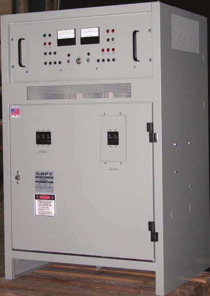

1 Float Battery Chargers Unfiltered SCR and Filtered SCRF Series Single Phase Input / Three Phase Input April 2006


2 SCR-SCRF Utility & General Industry Switchgear Alarm Systems Engine Starting Railroad Emergency Lighting Marine Communication & Telecommunications Radio Telephone Telemetering Microwave Saft's SCR/SCRF Series of industrial float chargers is designed to automatically control charging rates for a wide variety of battery types and to simultaneously provide full rated output for both continuous and intermittent DC loads. The chargers are constant voltage devices with automatic current limiting. Voltage regulation and current limiting are controlled by solid state integrated circuitry to assure maximum performance in minimum space. The SCR/SCRF Series is ideally suited to utility, communications and other stationary charger applications. Design Features Component Selection Electronic and electrical components are substantially derated to assure long life and reliability. Typical MTBF is 30,000 hours minimum. Components are selected or designed to provide a system life expectancy of 20 years. Modular Construction Control circuits, alarm circuits and electrical subassemblies are printed circuit board wired or modularized with plug and socket connections for easy serviceability. Standard Subassemblies Control modules and many electrical subassemblies are standardized across the entire range of charger sizes. This minimizes spare parts inventory and simplifies maintenance. Durable Front panels are recessed to prevent accidental damage to meters and controls. Standard cabinets are NEMA-1 enclosures of heavy gauge phosphatized steel with an attractive, long lasting acrylic enamel finish. Easy Troubleshooting A complete service manual, color-coded wiring, test point identification and circuit symbol labeling of internal components make troubleshooting easy. Ease of Adjustment Tap adjustments are not required. Output float voltage, equalize voltage, current limit and alarm levels are potentiometer adjustable. Ease of Access Internal components and connections are easily accessible and/or removable through a hinged front door that opens approximately 180 degrees for easy serviceability. Ease of Installation Cabinets are floor, wall or rack mountable and equipped with knockouts for cable or conduit entrance. Input, output and remote alarm connections are wired to easily accessible, internal terminal blocks. Environmental Specifications Operating Ambient Temperature 32 F to 122 F (0 C to 50 C) without derating. Storage Temperature -40 F to 185 F (-40 C to 85 C). Operating Altitude 3300 feet (00 meters) above sea level without derating. Relative Humidity 5% to 95% (without condensation). Audible Noise Less than 65 dba at any point 5 feet from any vertical surface of enclosure. Typical values measure 55 to 60 dba at 0% load. Ventilation Units rated 300 Adc output or less are convection cooled via NEMA-1 vent openings in cabinet. Units rated 400 Adc output or greater have fan-assisted convection cooling with overheat audible alarm and remote alarm contacts. (Automatic charger shutdown due to overheat is optional.) Electrical Specifications AC Input Standard transformers are available with taps for nominal voltages as listed below. Single Phase Voltages: 120/ V 47-63Hz 480V 57-63Hz 120/ V 47-63Hz (optional) Three Phase Voltages: 208/240V 57-63Hz V 47-63Hz 480V 57-63Hz Chargers are wired and circuit protected for one nominal input voltage and frequency (to be specified at time of order). Output Regulation ±0.5% of DC voltage setting maintained with input line variations of ±% voltage and/or ±5% frequency. ±0.5% of DC voltage setting maintained with load variations from no load to full load. ±1.0% of DC voltage setting maintained against the combined variations of line, load and temperature.
3 SCR-SCRF Output Transient Response & Recovery ±5.0% max. of DC voltage setting maintained with step load changes from 20% to 0% load. Recovery to ±2.0% of DC voltage setting, typically 200msec. Recovery to steady state DC voltage setting, typically 500msec. Overshoot of DC Voltage setting is not present at turn-on due to soft-start feature. Output Current Limit The electronic current limiting circuitry is factory set at 1% of rated output. It is continuously adjustable from 90% to 120% of rated load. Output Ripple and Electrical Noise* Unfiltered (SCR Series): Output ripple voltage is less than % rms for single phase input SCR units. Output ripple voltage is less than 3% rms for three phase input SCR units. Filtered (SCRF Series): Output ripple voltage is 30mVrms or less for all SCRF units. Electrical voice band noise is less than 32dBrnC using C-message weighting network. *Measure when connected to a battery with an 8hr Amp-Hour rating of 4 times the full load current rating of the charger. Random Parallel Operation SCR/SCRF Series Chargers may be random parallel operated with other chargers of similar regulation and current limit characteristics. Equal load sharing by two SCR/SCRF chargers requires the addition of the forced load sharing option. Battery Eliminator Operation SCRF Series Chargers will operate as DC power supplies without batteries. Addition of the Filtered Battery Eliminator option (SCRF units only) will reduce ripple when used as a battery eliminator. DC Output Fuses Two-pole, fast acting, current limiting rectifier type. AC and DC Surge Supressors - MOV Type AC Withstand 240Vac or less: 1500Vpk x 20 μsec pulse Over 240Vac or less: 3000Vpk x 20 μsec pulse DC Withstand All DC outputs: 4000Vpk x 20 μsec pulse DC Output Ammeter and Voltmeter Front panel, 2% accuracy, 3.5 inch case. Manual Float/Equalize Switch Front panel toggle switch. Float and Equalize Adjustment Potentiometers Two front panel mounted, lockable adjustment potentiometers. Current Limit Adjustment Potentiometer Internally mounted, with easily accessible adjustment. DC Output Blocking Diode Standard SCRF series feature prevents battery from discharging back through the filter and rectifier when charger is off due to AC power failure or charger malfunction. Standard SCR Series design provides the same protection on unfiltered units. DC Output Protection Diode Prevents damage to charger and battery due to reversed polarity connections. Color-Coded Internal Wiring 600 Volt, color-coded, polyvinylchloride (PVC) wiring is standard. Standard Accessories AC On Indicating Light Green front panel indicator AC Input Circuit Breaker Single Phase Input: Two-pole, 5000 A.I.C., UL Listed 0A-Frame Three Phase Input: Three-pole, 5000 A.I.C., UL Recognized 0A-Frame Three-pole, A.I.C., UL Listed 225A-Frame Three-pole, A.I.C., UL Listed 400A and 600A-Frame
4 Floa S (Time Unregulated AC Input 1φ or 3φ Typical SCR/SCRF Series One-Line Circuit Diagram AC Input Circuit Breaker Input Surge Protection AC On Indicating Light Power Isolation Transformer SCR/Diode Rectifier Bridge Filter S (SCR o Remot Remote Alarm Signal AC Power Failure Alarm (optional) Remot Control Power Remot Internal Alarm Signal (e.g., HVA) Charger Shutdown (optional) Control (Trigger) Module w/current Limit Adjustment Battery charger DC Output Table Vdc Nominal Float Adjustment Range (Vdc) Equalize Adjustment Range (Vdc) Adc Size Range Available* Lead-Acid Cell Capability** (No. of cells) Ni-Cd Cell Capability*** (No. of cells) 1φ Input 3φ Input Normal Reduced Normal Reduced to 0 60 to to 0 50 to [21] to 0 50 to [27] [42] to to [63] [98] to to [126] [196] * The discrete Adc sizes offered within the ranges listed above are: 6, 12, 16, 20, 25, 30, 35, 40, 50, 60, 75, 0, 125, 150, 175, 200, 250, 300, 400, 500, 600Adc. All sizes are rated at 0% load. Some current ratings are not available on certain chargers. Consult factory or current priced list for exact offerings. ** Based on Lead-Acid Float of 2.15 to 2.25V/Cell and Equalize of 2.25 to 2.40V/Cell. *** Based on Ni-Cd Float of 1.35 to 1.45V/Cell and Equalize of 1.50 to 1.60V/Cell. Greater cell capability indicated by [xx] can be obtained by slightly reducing float and equalize settings.
5 Section only) Reverse Current Polarity Protection Output Fuse Protection DC Output Circuit Breaker (optional) Output Surge Protection Regulated DC Output ote Alarm Signal Charger Failure Alarm (optional) ote Alarm Signal Hi-Low Voltage Alarm (optional) ote Alarm Signal Ground Detection Alarm (optional) Current Sense oat/equalize Selection er is Optional) Voltage Sense & Adjustment Typical Performance Curves 2.5 Output Regulation - Lead-Acid Batteries 0 Conversion Efficiency - Single Phase Charger Equalize Calcium-Float Antimony-Float Vdc/cell % Load Current limit adjustment 1.7 Output Regulation - Ni-Cd Batteries Vdc/cell % Load Conversion Efficiency - Single Phase Charger Equalize Float Vdc/cell % Load Current limit adjustment Vdc/cell % Load Note: No load loss is 5% or less of DC output power at 0% load. Values shown are for nominal AC input and typical DC output voltage settings.
6 OPTIONAL ACCESSORIES Alarm Relays for Remote Indication* Available with or without front panel alarm indicating lights. AC Power Failure Alarm: Provides alarm state when AC power fails or AC breaker is open. DC Ground Detection Alarms: Provides alarm state when a ground fault has occurred at either the + or - output terminal. High-Low DC Voltage Alarms: Provides high alarm state when battery is being overcharged and low alarm state when battery is near end of discharge. Charger Failure Alarm (No DC Current): Provides alarm state when charger output current is less than 2% of rated output for 30 seconds or more. Will also activate with AC power failure and/or DC breaker or fuse open. Battery Discharging Alarm: Provides alarm state when battery discharge current exceeds the charger recharge current. End of Discharge Alarm: Provides alarm state when battery has discharged to lowest system voltage limit. DC Current Limit Alarm: Provides alarm state when charger output current reaches the current limit setting. Common (Summary) Alarm: Provides a single alarm state when any one or all monitored alarm conditions exist on charger. *Alarm circuits provide one (1) set of dry form C contacts (SPDT) wired to a terminal strip for customer termination. Alarm circuits with two (2) sets of dry from C contacts (DPDT) are available without indicating lights at additional cost. Standard relay contacts are rated for resistive loads of: 120Vac, 28Vdc, 52Vdc, 130Vdc. Auxiliary relays are available for use with alarm circuits when alarm load exceeds the standard contact rating. Auxiliary relay contacts are rated for resistive loads of: 120Vac, 28Vdc, 130Vdc. Combined Alarm Status Charger Monitor* The following alarm relays are available combined together on a single board. Each relay has one (1) set of isolated, dry form C contacts (SPDT) wired to a terminal strip for customer connection. Two (2) sets of form C contacts (DPDT) are available at additional cost. High-Low AC Voltage Alarm Relay: With High and Low Indicating Lights, 15 second Time Delay on Alarm, Auto Reset. High DC Voltage Alarm Relay: With Indicating Light, 15 second Time Delay on Alarm, Auto Reset. Low DC Voltage Alarm Relay: With Indicating Light, 15 second Time Delay on Alarm, Auto Reset. Ground Detection Alarm Relay: With (+) Ground Detection Indicating Light and (-) Ground Detection Indicating Light, 15 second Time Delay on Alarm, Auto Reset. Charger Failure Alarm Relay: With Indicating Light, 30 second Time Delay on Alarm, Auto Reset. Common Alarm Relay: Summary Alarm Relay for any one or all alarms on this board. *Alarm contacts are rated for AC or DC. Indicating lights are red LED s front panel mounted. A Lamp Test switch is provided for verifying operation of indicating lights. Customer terminal strip is rated 120V AC or DC to accommodate #14AWG maximum wire. This option may be ordered without Ground Detection for DC systems that are referenced to ground. DC Ground Detection for Local Indication Ground Detection Switch for Front Panel DC Voltmeter Indication: Measures voltage from + or - output terminals to common ground. Ground Detection Indicating Lights with Ground Test & Lamp Test Switch: Front panel lamps indicate + or - output ground fault with switch in Ground Test position. In Lamp Test position both lights are verified as operational. Equalize Timers 0-72hr Manual Equalize Timer w/ or w/o Float Equalize Indicating Lights: Replaces Float/Equalize Switch. Charger automatically switches from Equalize to Float at end of set time interval. 0-72hr Line Failure Auto-Equalize Timer w/float Equalize Indicating Lights: Charger is switched to equalize for a set time interval after power is interrupted for seconds or more. Equipped with Float Reset and Equalize override switches. 0-72hr Current Limit Auto-Equalize Timer w/float Equalize Indicating Lights: Charger is switched to equalize for a set time interval after charger is in current limit for seconds or more. Equipped with Float Reset and Equalize override switches. DC Circuit Breaker Two pole DC Breaker is installed with one-pole standard fuse: 5000 A.I.C., UL Listed 0A-Frame 000 A.I.C., UL Listed 250 & 400A-Frame A.I.C., UL Listed 600 & 800A-Frame Forced Load Sharing Chargers operating in parallel share load to within 2% of output current of each charger. High DC Voltage Charger Shutdown A contact closure from a High DC Voltage Alarm activates the shutdown circuit and charger output current goes to zero. Filtered Battery Eliminator Output ripple voltage is 30mVrms or 0.06% of nominal output voltage, whichever is higher, without battery connected. Input Lightning Arrestors Provides additional input protection against lightning induced transients. Surge Withstand Capability Additional surge protection to meet performance requirements of IEEE-472 SWC Specification. AC Input Voltmeter and/or Ammeter Front panel, 2% accuracy, 3.5-inch case. Additional Optional Accessories Special input voltages and frequencies Special High Interrupting Capacity (A.I.C.) circuit breakers 1% accuracy panel or switchboard meters Alarm buzzer Device nameplates Fungus proofing (Tropicalization) Drip-proof cabinet shields Cabinet heater strips Special paint NEMA-4 or NEMA-12 cabinets Special SIS or Hypalon internal wiring Export packing
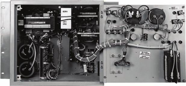
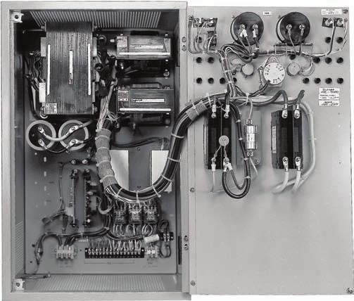
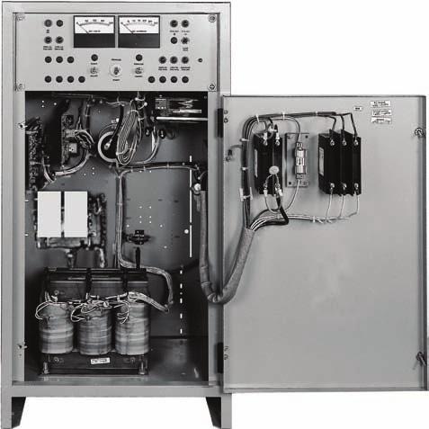
7 SCR-SCRF TYPICAL INTERNAL CONSTRUCTION DETAIL 1. DC Ammeter 2. DC Voltmeter 3. AC Power On Light 4. Equalize Adjust POT 5. Float Adjust POT 6. Equalize Timer (optional) Float/Equalize Switch (standard) 7. DC Circuit Breaker (optional) 8. DC Fuse(s) 9. AC Circuit Breaker. DC Surge Supressor 11. Status Indicating Lights & Switches 12. Power Isolation Transformer w/ac Reconnection T.B. 13. AC Surge Suppressors 14. SCR Rectifier/Heat Sink Assembly 15. Polarity & Blocking Diode Assembly(s) 16. Filter Choke(s) 17. Bleeder Resistor 18. Filter Capacitor(s) 19. Alarm Relay(s) (optional) 20. Alarm Control Module(s) (optional) 21. Control Module 22. Current Limit Adjust POT 23. Input Line & Ground Terminals (TB1) 24. Output Terminals (TB2) 25. Remote Alarm Terminals (TB3) Note: Component placement may vary due to options selected. Style 1A Cabinet Construction Style 1B Cabinet Construction Style 2 Cabinet Construction
8 BATTERY CHARGER, SIZE & DATA TABLE 12Vdc 24Vdc 48Vdc 130Vdc 260Vdc AMPERE RATING Single Phase Input A 80 (36) 95 1A 90 (41) 170 1A 5 (48) 370 1B 125 (57) (4) A 90 (41) 200 1A 5 (48) 330 1A 120 (54) 740 1B 160 (73) A 98 (44) 260 1A 115 (52) 440 1B 135 (61) 990 1B 2 (95) (145) A 5 (48) 320 1A 125 (57) 540 1B 160 (73) B 220 (0) B 120 (54) 400 1B 135 (61) 680 1B 170 (77) B 230 (4) (222) B 130 (59) 480 1B 150 (68) 8 1B 190 (86) B 250 (113) B 135 (61) 560 1B 160 (73) 950 1B 2 (95) (154) B 145 (66) 640 1B 180 (82) 80 1B 220 (0) B 160 (73) 800 1B 190 (86) (111) (200) (84) (95) (93) (111) (150) (127) (145) (200) Three Phase Input (159) (136) (231) (150) (161) (254) (172) (95) (116) (227) (268) (98) (9) (145) (236) (9) (125) (159) (249) (404) (143) (163) (209) (308) (454) (193) (227) (340) (218) (245) (415) (671) (231) (272) (458) (249) (295) (680) (730) (272) (340) (635) (322) (390) (680) (885) (354) (431) (748) (386) (612) (826) (420) (680) (885) * Heat loss in BTU/HR is stated for nominal number of cells at float voltage and 0% DC load current. Ordering Information Specify: Charger Model #XSCRX XXX - XXX - X 1 for 1 phase 3 for 3 phase Omit for unfiltered F for filtered 012, 024, 048, 130 or 260 nominal Vdc output Nominal input (Vac) and frequency (Hz) Number and type of battery cells All optional accessories required on charger Omit if not required E for filtered battery eliminator (SCRF units only) 006 to 600 rated Adc output Cabinet Dimensions* 1A 1B Mounting Type Wall** Wall** Floor** Floor Floor Floor H Dimensions ¼ 37 ⅜ in M.M. W 18 ¼ ⅜ (inches) D 12 ⅛ 15 ½ 14 ¾ ** Rack mounting cabinet is optional for these styles. Saft 3 Powdered Metals Drive North Haven, CT USA TEL FAX Doc N o XXXXX-X-XXXX Edition: April 2006 Data in this document is subject to change without notice and becomes contractual only after written confirmation.
FLOAT BATTERY CHARGERS
 FLOAT BATTERY CHARGERS UNFILTERED SCR SERIES FILTERED SCRF SERIES SINGLE PHASE INPUT THREE PHASE INPUT Applications for: UTILITY & GENERAL INDUSTRY Switchgear Engine Starting Emergency Lighting Alarm Systems
SCR/SCRF SERIES. Industry s First Choice for Time-Tested Proven Reliability FLOAT BATTERY CHARGERS. Single-Phase Input
 SCR/SCRF SERIES FLOAT BATTERY CHARGERS Industry s First Choice for Time-Tested Proven Reliability Single-Phase Input Three-Phase Input Applications for: Utility & General Industry Switchgear Engine starting
AT10.1 Series Microprocessor-Controlled Float Battery Charger (single phase input)
") STANDARD SAMPLE SPECIFICATION AT10.1 Series Microprocessor-Controlled Float Battery Charger (single phase input) A battery charger shall be furnished in accordance with the following specification: 1.0
STANDARD SAMPLE SPECIFICATION AT10.1 Series Microprocessor-Controlled Float Battery Charger (single phase input) A battery charger shall be furnished in accordance with the following specification: 1.0
Revision: None DCN No. First Issue Date: November 30, 1998 Product: Standard DCT, 120-volts
 Figure 1Document: SPEC-112 Revision: None DCN No. First Issue Date: November 30, 1998 Product: Standard DCT, 120-volts construction requirements of UL approved Class H (180 C) insulation system. Transformers
R E C T I F I E R I N V E R T E R C O N V E R T E R SB7
 SCR Battery Charger Product Specifications Description The is RIC Electronics premiere SCR battery charger/rectifier. The provides power to critical DC loads through a wide range of outputs and is engineered
UltraLITE Model ELU Centralized Emergency Lighting Inverter 4.2 KW- 5 KW
 12/23/16 Rev 9 UltraLITE Model ELU General Specification 4.2 KW to 5 KW UltraLITE Model ELU Centralized Emergency Lighting Inverter 4.2 KW- 5 KW 1.0 General General Specification This specification describes
PS6 SERIES. Installation PS6 SERIES. Power Supplies c/w Fire Panel Interface, EOL Trigger and Standby Power Option
 Installation PS6 SERIES Power Supplies PS6 SERIES Power Supplies c/w Fire Panel Interface, EOL Trigger and Standby Power Option Installation and Specifications Manual ISDPS6_SERIES 08121590 PCN15016 R05/15GR
LORAIN CIP 4890/48120 DC Power System
 DC Power for Business-Critical Continuity Key Features Compact flexibility provides rectifiers, distribution, and controller in one shelf Constant power delivers more current at lower voltages to meet
LORAIN CSP DC Power System
 DC Power for Business-Critical Continuity Key Features Compact flexibility provides more space for revenue generating equipment Constant power delivers more current at lower voltages to meet load or recharge
Model LTN-3R Outdoor Rated Uninterruptible Power System Single Phase
 Model LTN-3R Outdoor Rated Uninterruptible Power System Single Phase General Specification 550 VA/Watts 1300 VA/Watts 1.0 GENERAL This specification defines the electrical and mechanical characteristics
FireSystem 2000 Commercial and Light Industrial Fire Alarm Control Panel
 PROTECTOWIRE FireSystems Features Easily expandable Two supervised audible circuits Lamp and system trouble circuit test Ground fault detection Initiating device circuit (IDC) alarm test Monitors up to
elite Model ELN Centralized Emergency Lighting Inverter Systems 550 W to 1.5 KW Systems
 5/25/16 rev 6 elite Model ELN General Specification 550 W to 1.5 KW elite Model ELN Centralized Emergency Lighting Inverter Systems 550 W to 1.5 KW Systems 1.0 General General Specification This specification
SECTION AUTOMATIC TRANSFER SWITCHES
 PART 1 - GENERAL 1.1 DESCRIPTION SECTION 26 36 23 This section specifies the furnishing, complete installation, and connection of automatic transfer switches. 1.2 RELATED WORK A. Section 14 21 00, ELECTRIC
FDF Foam Pump Controllers Features
 FDF100 Diesel Engine Foam Pump Controllers 1-1 Product Description The FDF Series of Foam Pump Controllers are designed for use with foam concentrate injection, foam transfer and water mist systems for
Rectifier RC-series. Manual RC-series English MA doc. Manual Wall and 19 English
 Rectifier RC-series Manual RC-series English Manual Wall and 19 English Presentation The RC-series is a rectifier for either directly powering the load or for use together with batteries. It is designed
Commercial and Light Industrial Fire Alarm Control Panel
 FireSystem 2000 Commercial and Light Industrial Fire Alarm Control Panel Features Easily expandable. All new plug-in board design Two supervised audible circuits Lamp and system trouble circuit test Ground
Installation Guide for models:
 140 58th St. Brooklyn, NY Access Power Controllers with Power Supplies Installation Guide for models: Maximal3FD - 12VDC @ 4.6 amp or 24VDC @ 5.2 amp. - Sixteen (16) PTC protected power-limited outputs.
B. Section Transfer Switches: Automatic transfer switch.
 SECTION 263213 - ENGINE GENERATORS PART 1 GENERAL 1.1 SECTION INCLUDES A. Packaged engine generator set. B. Exhaust silencer and fittings. C. Remote control panel. D. Battery and charger. E. Weatherproof
Public Safety DAS Annunciator Panel
 Public Safety DAS Annunciator Panel 120 VAC Models: 1221-A, 1221-B, 1221-C Revision D 91117 48 VDC Models: 1221-A-48, 1221-B-48, 1221-C-48 24 VDC Models: 1221A-24, 1221-B-24, 1221-C-24 CAUTION: (Read This
La Marche Manufacturing Company Option 16 Series. Digital Combined Accessory Package. Installation and Operation Manual
 La Marche Manufacturing Company www.lamarchemfg.com Option 16 Series Digital Combined Accessory Package Installation and Operation Manual This manual is subject to change without notice. You may obtain
Installation Guide for AL600ULM. Multi-Output Access Control Power Supply Charger. Rev
 Installation Guide for AL600ULM Multi-Output Access Control Power Supply Charger Rev. 091800 1 AL600ULM - Multi-Output Access Control Power Supply/Charger Overview: The AL600ULM multi-output access control
Spectron LSN (Life Safety Network) Suggested Specifications
 Suggested Specifications") 1. General 1.1 Scope A Dual-Lite Spectron LSN (Life Safety Network) Series Inverter System shall be furnished to provide a reliable source of power, and shall operate during a utility line deficiency without
1. General 1.1 Scope A Dual-Lite Spectron LSN (Life Safety Network) Series Inverter System shall be furnished to provide a reliable source of power, and shall operate during a utility line deficiency without
ACSI AO ELECTRIC LATCH RETRACTION CONTROLLER INSTALLATION INSTRUCTIONS I.D. 1089, REV. F
 II 1400-2 ACSI 1406-04-AO ELECTRIC LATCH RETRACTION CONTROLLER INSTALLATION INSTRUCTIONS I.D. 1089, REV. F INSTALLATION Transformer Model BE31763001 by Basler Electric, Transformer Model 2010028 by Galaxy
MS-4012/4024 and CMS-4012/4024. Instruction Manual for the. Fire Alarm Control Panels
 R 12 Clintonville Road, Northford, CT 06472 Phone: (203) 484-7161 FAX: (203) 484-7118 Instruction Manual for the MS-4012/4024 and CMS-4012/4024 Fire Alarm Control Panels Document 15586 5/11/93 Revision:
DIESEL Engine Fire Pump Controllers Features
 September 007 DIESEL Engine Fire Pump Controllers Features FD0 Diesel Engine Controllers 1-1 Printer / Recorder The industrial grade thermal printer is housed in a rugged steel enclosure within the controller.
www. ElectricalPartManuals. com GADD MKIII Ground Fault Indication System Instruction Manual Ground Fault Protection
 Ground Fault Protection GADD MKIII Ground Fault Indication System Instruction Manual 7615 Kimbel Street, Mississauga, Ontario Canada L5S 1A8 Tel: (905)673-1553 Fax: (905)673-8472 Toll Free: 1-888-RESISTR
Loadstar AC/DC Systems
 WARRANTY W A R R A N T Y YEAR The Loadstar range of AC/DC central battery units comply with the latest relevant European and British standards. High quality, cost effective units provide secure sources
Installation Guide for models:
 140 58th St. Brooklyn, NY Access Power Controllers with Power Supplies Installation Guide for models: Maximal11F - Power Supply 1: 12VDC @ 3.3 amp or 24VDC @ 3.6 amp. - Power Supply 2: 12VDC @ 3.3 amp
ILLUMINATOR E & IE CENTRAL INVERTER FOR EMERGENCY LIGHTING
 ILLUMINATOR E & IE CENTRAL INVERTER FOR EMERGENCY LIGHTING THE ILLUMINATOR ILLUMINATOR SERIES IE The Illuminator Series IE is an interruptible lighting inverter. It transfers to inverter mode (battery
Pioneer-R16 Gas Monitor Operator s Manual
 Pioneer-R16 Gas Monitor Operator s Manual Edition 7/2/97 RKI INSTRUMENTS, INC RKI Instruments, Inc. 33248 Central Ave, Union City, CA 94587 (510) 441-5656 Chapter 1: Description About the Pioneer-R16 Gas
Model 4001 Series Single Channel Controller
 Model 4001 Series Single Channel Controller Sierra Monitor Corporation 1991 Tarob Court, Milpitas, CA 95035 (408) 262-6611 (800) 727-4377 (408) 262-9042 - Fax E-Mail: sales@sierramonitor.com Web site:
ILLUMINATOR EM. CENTRAL LIGHTING INVERTER 1000 VA/W through 2800 VA/W 98% Efficiency!
 ILLUMINATOR EM CENTRAL LIGHTING INVERTER 1000 VA/W through 2800 VA/W 98% Efficiency! THE ILLUMINATOR SERIES EM The Illuminator Series EM is a fast transfer Emergency Lighting Inverter utilizing Myers Power
TECHNICAL DATA. multi-hazard. model vfr400. Release Control Panel 290a. January 16, 2014
 January 16, 2014 Release Control Panel 290a 1. Description The Viking VFR400 is a microprocessor based releasing control panel for use on preaction, deluge, Surefire, Firecycle multicycle sprinkler systems,
Remote NAC Power Supply D7038
 Operation and Installation Guide Remote NAC Power Supply D7038 D7038 REMOTE NAC POWER SUPPLY Page 2 2005 Bosch Security Systems Contents Contents 1.0 Overview...5 1.1 Module Control...5 1.1.1 Option Bus
Utility Battery Chargers DC Power Systems Custom Design
 Utility Battery Chargers DC Power Systems Custom Design Hindle Transformer Company founded 1948 Hitran Corporation Flemington, NJ HindlePower, Inc. Easton, PA, Incorporated 2000 40,000 sq. ft. Facility
VACUUM BREAKER MEDIUM VOLTAGE AUTOMATIC TRANSFER SWITCHES
 Part One General 1.01 Scope A. It is the intent of this specification to provide a medium voltage automatic transfer system. B. All components, testing and services specified and required for a complete
SECTION AUTOMATIC TRANSFER SWITCHES
 PART 1 - GENERAL 1.1 DESCRIPTION SECTION 26 36 23 SPEC WRITER NOTE: Use this section only for NCA projects. Delete between //--// if not applicable to project. Also, delete any other item or paragraph
Installation Guide for AL400ULM. Multi-Output Access Control Power Supply Charger
 Installation Guide for AL400ULM Multi-Output Access Control Power Supply Charger R AL400ULM - Multi-Output Access Control Power Supply/Charger Rev. 072500 Overview: The AL400ULM multi-output access control
ELECTRONIC FLAME SUPERVISION MULTI-BURNER
 MULTI-BURNER MODEL: SENS-A-FLAME II Revision: 0 7112 DESCRIPTION Model 7112 Sens-A-Flame II is a second generation solid-state programmable combustion safeguard for supervising multiple burner ovens, furnaces,
SECTION AUTOMATIC TRANSFER SWITCHES PART 1 - GENERAL
 SECTION 16400 AUTOMATIC TRANSFER SWITCHES 1.01 RELATED DOCUMENTS PART 1 - GENERAL A. Drawings and general provisions of Contract, including General Conditions and Division 1 Specification sections, apply
Models NFPA 1221-A, NFPA 1221-B Public Safety DAS Annunciator Panel. Revision E 61117
 Models NFPA 1221-A, NFPA 1221-B Public Safety DAS Annunciator Panel Revision E 61117 CAUTION: (Read This First) This panel has been designed to make it nearly bullet proof to mistakes made when wiring
IMPORTANT SAFEGUARDS READ AND FOLLOW ALL SAFETY INSTRUCTIONS. HZM-Series-Class I, Div 2 Battery Unit. Instalation instructions
 HZM-Series-Class I, Div 2 Battery Unit HZM-Series-Class I, Div 2 Battery Unit Instalation instructions IMPORTANT SAFEGUARDS 1 4 5 6 7 13 When using electrical equipment, basic safety precautions should
DIESEL ENGINE CONTROL UNIT DCU USER S MANUAL - N-2000 Lillestrøm, Norway Tel: (+47) Fax: (+47)
 Fax: (+47)") DIESEL ENGINE CONTROL UNIT DCU 205 - USER S MANUAL - N-2000 Lillestrøm, Norway Tel: (+47) 64 84 52 00 Fax: (+47) 64 84 52 12 office@auto-maskin.no - 1 - TABLE OF CONTENTS 1. INTRODUCTION TO THE DCU 205...4
DIESEL ENGINE CONTROL UNIT DCU 205 - USER S MANUAL - N-2000 Lillestrøm, Norway Tel: (+47) 64 84 52 00 Fax: (+47) 64 84 52 12 office@auto-maskin.no - 1 - TABLE OF CONTENTS 1. INTRODUCTION TO THE DCU 205...4
LC2200 Level Controller Installation and Maintenance Instructions
 4025250/9 IM-P402-77 AB Issue 9 LC2200 Level Controller Installation and Maintenance Instructions LC2200 ALARM TEST >50% >100%
La Marche Manufacturing Company A36D. Battery Charger / Power Supply. Installation and Operation Manual
 La Marche Manufacturing Company www.lamarchemfg.com A36D Battery Charger / Power Supply Installation and Operation Manual 106 Bradrock Dr. Des Plaines, IL 60018-1967 Tel: 847 299 1188 Fax: 847 299 3061
La Marche Manufacturing Company Option 46 Series. Digital Combined Accessory Package. Installation and Operation Manual
 La Marche Manufacturing Company www.lamarchemfg.com Option 46 Series Digital Combined Accessory Package Installation and Operation Manual This manual is subject to change without notice. You may obtain
TECHNICAL DATA. Humidity: 85% Relative Humidity (non-condensing) at 90 F (32 C) maximum.
 at 90 F (32 C) maximum.") September 29, 1997 Firecycle III 433 a 1. PRODUCT NAME VIKING Model E-1 Manufactured 1997 Present 2. MANUFACTURED FOR THE VIKING CORPORATION 210 N Industrial Park Road Hastings, Michigan 49058, U.S.A.
September 29, 1997 Firecycle III 433 a 1. PRODUCT NAME VIKING Model E-1 Manufactured 1997 Present 2. MANUFACTURED FOR THE VIKING CORPORATION 210 N Industrial Park Road Hastings, Michigan 49058, U.S.A.
ANALOX 3000 Carbon Monoxide Monitor
 ANALOX 3000 Carbon Monoxide Monitor User Manual Analox Sensor Technology Ltd 15 Ellerbeck Court, Stokesley Business Park North Yorkshire, TS9 5PT T: +44 (0)1642 711400 F: +44 (0)1642 713900 W: www.analox.net
Sierra Series 900 Single & Dual Channel System. Instruction Manual
 Series 240/24 Instruction Manual Table of Contents Sierra Series 900 Single & Dual Channel System Instruction Manual Part Number IM-90-07/05 Revision D. 5 Harris Court, Building L Monterey, CA 93940 (83)
Constant voltage 3-phase rectifier.
 11750a Constant voltage 3-phase rectifier. Page 1 of 11 11750a Mechanical assembly The rectifier is assembled in a cabinet intended for indoor wall mounting. The cabinet has ventilation holes on both sides
ESSEX ENGINEERING CORPORATION
 WATER/WASTEWATER TREATMENT CONTROL SYSTEMS AND SUBSYSTEMS 2000 SERIES CONTROL SYSTEMS: 2000 series are for surface mounting inside a control cabinet Model 2024 Electronic Alternator Duplex (two pump) pump
ILLUMINATOR E & IE CENTRAL INVERTER FOR EMERGENCY LIGHTING
 ILLUMINATOR E & IE CENTRAL INVERTER FOR EMERGENCY LIGHTING ALSO AVAILABLE FROM MYERS POWER PRODUCTS: ILLUMINATOR SERIES CIII 4.8 kva TO 50 kva THREE PHASE ILLUMINATOR CM 500 VA TO 2000 VA SINGLE PHASE
Installation Guide for AL300ULM. Multi-Output Access Control Power Supply Charger
 Installation Guide for AL300ULM Multi-Output Access Control Power Supply Charger R AL300ULM - Multi-Output Access Control Power Supply/Charger Overview: The AL300ULM multi-output access control power supply/charger
Installation, Operating and Maintenance Manual
 STATUS ZONES CONTROLS FIRE FAULT DISABLED FIRE 1 2 3 4 5 6 7 8 TEST FAULT DISABLED 1 5 BUZZER SILENCE RESET 1 2 TEST 2 6 LAMP TEST 3 SUPPLY 3 7 SYSTEM FAULT 4 8 SOUNDERS ACTIVATE/ SILENCE 4 FAULTS INSTRUCTIONS
SECTION AUTOMATIC TRANSFER SWITCHES
 SECTION 26 36 23 AUTOMATIC TRANSFER SWITCHES PART 1 - GENERAL 1.1 RELATED DOCUMENTS A. General provisions of the Contract, including General and Supplementary Conditions and Division 01 Specification Sections,
Installation and user manual for the FX range of fire panels. 1, 2, 4 and 8 zone panels
 Installation and user manual for the FX range of fire panels 1, 2, 4 and 8 zone panels Contents Panel installation 3 Panel connections 3 Wiring connection drawings 4 Panel facilities 6 Installation check
IMPORTANT SAFEGUARDS READ AND FOLLOW ALL SAFETY INSTRUCTIONS. 3LERHZ Series Class I, Div 2 Combo Unit. Installation instructions
 3LERHZ Series Class I, Div 2 Combo Unit Installation instructions 3LERHZ Series Class I, Div 2 Combo Unit IMPORTANT SAFEGUARDS 1 3 When using electrical equipment, basic safety precautions should always
RE-PR3-E-27 3-Phase Panel Mount 27kW
 Page 1 of 6 RE-PR3-E-27 3-Phase Panel Mount 27kW Features: Benefits: 0-10Vdc, 0-5Vdc, 4-20mA or manual via potentiometer control input Over temperature protection with auto reset Enclosed panel mounting
Installation Guide for AL800UL-ADA. NAC Power Extender. Rev
 Installation Guide for AL800UL-ADA NAC Power Extender Rev. 090500 Overview: The Altronix AL800UL-ADA is an extremely cost effective 8 amps voltage regulated remote power supply /battery charger. The AL800UL-ADA
Table of Contents. Protective Relays
 Table of Contents KILOVAC WD Series, DIN Rail or Screw Mounted Introduction..........................................................11-2 KILOVAC WD25 Paralleling Relays........................................11-3
Installation and user manual for the CF5000, MF5000 and FXP5000 range of fire panels
 CF5000, MF5000 and FXP5000 Installation and user manual for the CF5000, MF5000 and FXP5000 range of fire panels 16 zone panels Contents PANEL INSTALLATION...3 Installation...3 PANEL WIRING... 3 Mains power
Installation Manual CFP-105. Fire Alarm Control Panel. Version 1.0
 CFP-105 Fire Alarm Control Panel Installation Manual Version 1.0 WARNING: This manual contains information on limitations regarding product use and function and information on the limitations as to liability
MR-2602 Two Zone Fire Alarm Control Panel
 MR-2602 Two Zone Fire Alarm Control Panel Installation Manual Secutron LT-2015 Rev.3 July 2010 Table of Contents 1 Introduction 1.1 The MR-2602 Fire Alarm Control Unit... 11 1.1.1 General features...
ECC-50/100C. Emergency Command Center
 ECC-50/100C Emergency Command Center Canadian DF-60815:B Emergency Communications General Fire-lite s ECC-50/100C is a multipurpose emergency voice evacuation panel for fire applications, mass notification
www. ElectricalPartManuals. com GADP Ground Fault Indication System Instruction Manual Ground Fault Protection
 Ground Fault Protection GADP Ground Fault Indication System Instruction Manual 7615 Kimbel Street, Mississauga, Ontario Canada L5S 1A8 Tel: (905)673-1553 Fax: (905)673-8472 Toll Free: 1-888-RESISTR 737-4787
Dale Power Solutions Ltd
 DC THYRISTOR SYSTEMS DATASHEET Features Erskine Single Phase Input DCV Range 24V, 48/50V or 110V nominal Up to 63 Amps per charger Constant voltage/current limited output Standard alarm module LCD metering
ANALOX 5001 Carbon Dioxide Monitor. User Manual ANALOX Analox 5001 Carbon Dioxide Monitor User Manual
 ANALOX 5001 ANALOX 5001 Carbon Dioxide Monitor User Manual Analox Sensor Technology Ltd 15 Ellerbeck Court, Stokesley Business Park North Yorkshire, TS9 5PT T: +44 (0)1642 711400 F: +44 (0)1642 713900
Fire Control/Communicator
 Operation and Installation Manual Fire Control/Communicator 1 2 3 4 5 12V AC,20V A, 60Hz or +24V DC 12V AC, 20V A, 60Hz or -24V DC EARTH GND BATTERY - BATTERY + 6 INITIATING A1-7 INITIATING A2-8 INITIATING
CONTENTS AUTOMATIC TRANSFER SWITCHES
 CONTENTS AUTOMATIC TRANSFER SWITCHES PART 1 GENERAL 1.1 Related Documents 1.2 Summary 1.3 References 1.4 Quality Assurance 1.5 Submittals 1.6 Delivery, Storage and Handling 1.7 Instructions And Training
1.1 REFERENCES.1 American National Standards Institute/National Fire Protection Association (ANSI/NFPA).1 ANSI/NFPA 20, Centrifugal Fire Pumps.
.1 ANSI/NFPA 20, Centrifugal Fire Pumps.") Issued 2006/08/01 Section 13920 Packaged Fire Pumps and Controllers Page 1 of 7 PART 1 GENERAL 1.1 REFERENCES.1 American National Standards Institute/National Fire Protection Association (ANSI/NFPA).1
Issued 2006/08/01 Section 13920 Packaged Fire Pumps and Controllers Page 1 of 7 PART 1 GENERAL 1.1 REFERENCES.1 American National Standards Institute/National Fire Protection Association (ANSI/NFPA).1
EG Controls. SLIMVIEW 120 VOLT FLOAT SERIES DUPLEX PUMP CONTROL PANEL SPECIFICATION for CITY OF E G
 E SLIMVIEW 120 VOLT FLOAT SERIES DUPLEX PUMP CONTROL PANEL SPECIFICATION for CITY OF DATE: 11/13/06 2/1/07 1 Copyright, E, Inc. E 1. ENERAL...4 1.1 Scope Of Work... 4 1.2 Codes and Standards... 4 2. PRODUCTS...5
ECC-50/100(E) Emergency Command Center. General. Features. Emergency Voice Evacuation TYPICAL APPLICATIONS
 Emergency Command Center. General. Features. Emergency Voice Evacuation TYPICAL APPLICATIONS") ECC-50/100(E) Emergency Command Center DF-60734:A4 General Firelite s ECC-50/100 and ECC-50/100E are multipurpose emergency voice evacuation panels for fire applications, mass notification applications,
ECC-50/100(E) Emergency Command Center DF-60734:A4 General Firelite s ECC-50/100 and ECC-50/100E are multipurpose emergency voice evacuation panels for fire applications, mass notification applications,
Multi-Output Access Control Power Supply Charger VDC or 24VDC VDC or 3 24VDC.
 M Series Multi-Output Access Control Power Supply Charger Installation Guide Models Include: AL300ULM AL400ULM - 2.5 amp @ 12VDC or 24VDC. - 4 amp @ 12VDC or 3 amp @ 24VDC. AL600ULM AL1012ULM - 6 amp @
HOKKIM INTEGRATED AMF CONTROL BOARD MANUAL FOR MODELS: HAMF-8 AND HAMF-4
 HOKKIM INTEGRATED AMF CONTROL BOARD MANUAL FOR MODELS: HAMF-8 AND HAMF-4 INTRODUCTION Thank you for purchasing the Hokkim Integrated Automatic Mains Failure Control Board model HAMF- 8 or HAMF-4. We shall
TT /97. Features INSTALLATION INSTRUCTIONS. Horn. Lamps
 TT-1023 1/97 INSTALLATION INSTRUCTIONS Original Issue Date: 2/94 Model: 6-2000 kw Market: Industrial Subject: Flush- or Surface-Mount Remote Annunciator Kits PA-293991 and PA-293991-SD The remote annunciator
IMPORTANT SAFEGUARDS READ AND FOLLOW ALL SAFETY INSTRUCTIONS SAVE THESE INSTRUCTIONS. NXM Series - Survive-All. Emergency Light Unit
 Emergency Light Unit IMPORTANT SAFEGUARDS When using electrical equipment, basic safety precautions should always be followed including the following: READ AND FOLLOW ALL SAFETY INSTRUCTIONS 1. Do not
Booster Power Supply Manual
 Supply Manual DEVELOPED BY COPYRIGHT NOTICE General Signal Building Systems Corporation 6411 Parkland Drive Sarasota, FL 34243 (941) 739-4300 Copyright 1999 General Signal Building Systems Corporation
SECTION POWER SUPPLIES AND DISTRIBUTION
 SECTION 17460 PART 1 - GENERAL 1.01 DESCRIPTION A. Section includes requirements for Power Supplies and Power Distribution for Station communications. 1.02 REFERENCE STANDARDS A. American National Standards
Across-the-Line SERIES MP300 Combined Manual and Automatic
 Across-the-Line SERIES MP300 Combined Manual and Automatic Metron Fire Pump Controllers conform to the latest requirements of National Fire Protection Association s Standard for Centrifugal Fire Pumps
Soft Start Series MP700 Solid State, Reduced Voltage
 Metron Fire Pump Controls and Accessories Soft Start Series MP700 Solid State, Reduced Voltage Metron Fire Pump Controllers conform to the latest requirements of National Fire Protection Association s
For a red enclosure add an R suffix to the part # e.g. eflow4na8dr. Altronix Corp th St. Brooklyn, NY. Installing Company: Service Rep.
 Power Supply/Chargers Installation Guide Models Include: eflow4na8d - 4A @ 12VDC or 24VDC - Eight (8) PTC Outputs eflow6na8d - 4A @ 12VDC or 24VDC - Eight (8) PTC Outputs eflow102na8d - 10A @ 12VDC - Eight
Analox 1000 Series. User Manual. Analox Sensor Technology Ltd. 15 Ellerbeck Court, Stokesley Business Park North Yorkshire, TS9 5PT, UK
 Analox 1000 Series User Manual Analox Sensor Technology Ltd. 15 Ellerbeck Court, Stokesley Business Park North Yorkshire, TS9 5PT, UK T: +44 (0)1642 711400 F: +44 (0)1642 713900 W: www.analox.net E: info@analox.net
UC700 EMERGENCY TRANSFER SYSTEM SPECIFIER S HANDBOOK. 40 Dale Street West Babylon, NY Ph: Fx:
 UC700 EMERGENCY TRANSFER SYSTEM SPECIFIER S HANDBOOK 40 Dale Street West Babylon, NY 11704 Ph: 631-753-9550 Fx: 631-753-9560 www.unionconnector.com Emergency Automatic Transfer System STANDARD SPECIFICATIONS
Constant voltage charger. Type UP 610. »We store the world's energy« Network
 Type UP 610»We store the world's energy« Switchmode rectifier that fulfil new standards > New technique - sine wave input (PFC) > New princip - fully equipped > New technlogy - easy to use > High rate
Multi-Output Access Control Power Supply Chargers VDC or 24VDC VDC or 4 24VDC.
 M Series Multi-Output Access Control Power Supply Chargers Installation Guide Models Include: AL300ULM AL400ULM - 2.5 amp @ 12VDC or 24VDC. - 3 amp @ 12VDC or 4 amp @ 24VDC. AL600ULM AL1012ULM - 6 amp
Operating & Maintenance Manual. Alert-4 Ethernet LCD Master Alarm
 Operating & Maintenance Manual Alert-4 Ethernet LCD Master Alarm w w w. a m i c o. c o m Contents User Responsibility 4 Introduction 4 Features 5 Description of the Alarm 5 Shipment Details 5 The Alarm
# amp # amp 12/24 VDC POWER SUPPLY INSTALLATION MANUAL. 4202/4MA, Rev. E 0804
 #4202 2 amp #4204 4 amp 12/24 VDC POWER SUPPLY INSTALLATION MANUAL 4202/4MA, Rev. E 0804 4202/4204 Power Supply Fused 115 V Input Low Battery Indicator DC Output Adjustable 0.7 to 3.7 Volts from nominal
LC1 & 2. Fire Alarm Panel 6\VWHPLQVWDOODWLRQRSHUDWLQJ PDLQWHQDQFH LQVWUXFWLRQV
 LC1 & 2 Fire Alarm Panel 6\VWHPLQVWDOODWLRQRSHUDWLQJ PDLQWHQDQFH LQVWUXFWLRQV ZIRCONLC1 One Zone Conventional Fire Panel ZIRCONLC2 Two Zone Conventional Fire Panel Compliant with EN54-2:1998 & EN54-4:1998
Securitron Magnalock Corporation S. 51 st St., Ste. 102 Phoenix, AZ Phone: (800) MAGLOCK
 MAGLOCK") Installation Manual AQM-20 12vdc/24vdc Series Power Supplies AQM20 Supervised Power Supply/Charger 12vdc 20Amp/24vdc 10Amp Life Time Warranty Quality Manufactured in the USA AQM20 Features: The AQM20 has
Installation Manual AQM-20 12vdc/24vdc Series Power Supplies AQM20 Supervised Power Supply/Charger 12vdc 20Amp/24vdc 10Amp Life Time Warranty Quality Manufactured in the USA AQM20 Features: The AQM20 has
AL800ULADA. NAC Power Extender. Installation Guide
 AL800ULADA NAC Power Extender Installation Guide Rev. 122000 AL800ULADA - NAC Power Extender Overview: The Altronix AL800ULADA is an extremely cost effective 8 amp voltage regulated remote power supply/battery
SECTION CENTRAL BATTERY INVERTERS. A. This Section includes fast-transfer central battery inverters with the following features:
 PART 1 - GENERAL 1.1 SUMMARY A. This Section includes fast-transfer central battery inverters with the following features: 1. Emergency-only circuits. 1.2 DEFINITIONS A. LCD: Liquid-crystal display. B.
APC BC300 Series 40kW 208/450/480V User Guide
 APC BC300 Series 40kW 208/450/480V User Guide Copyright 2002 APC Denmark ApS This manual is subject to change without notice and does not represent a commitment on the part of the vendor Thank You Thank
Beacon 200 Gas Monitor Operator s Manual. Part Number: RK Released: 6/6/08
 Beacon 200 Gas Monitor Operator s Manual Part Number: 71-2102RK Released: 6/6/08 Table of Contents Chapter 1: Introduction.................................................3 Overview.............................................................3
MADE IN THE U.S.A. ADVANCE FIRE CONTROL MODEL LM21-AFC MANUAL RELEASE DEVICES TEST WEEKLY TO ASSURE PROPER OPERATION OF RELEASE DEVICE/CONTROL PANEL
 RELEASE DEVICES MADE IN THE U.S.A. ADVANCE FIRE CONTROL MODEL LM21-AFC MANUAL The LiftMaster Fire Control (LM21-AFC) Release Device/Control Panel is UL/CUL listed normally energized fail-safe device incorporating
ACC-25/50ZST. Zoned System Voice with Telephone Evacuation Control Panel
 ACC-25/50ZST Zoned System Voice with Telephone Evacuation Control Panel General The AUDIO COMMAND CENTER 25/50 Zone System with FireFighters Telephone (ACC-25/50ZST) is a state-of-the-art Emergency Voice
TECHNICAL DATA OBSOLETE
 Deluge Devices 270a 1. PRODUCT NAME VIKING PAR-3 Available since 1991 2. MANUFACTURED FOR: THE VIKING CORPORATION 210 N. Industrial Park Road Hastings, Michigan 49058 U.S.A. Telephone: (269) 945-9501 (877)
1. Division 26 Section Electrical General Requirements. 2. Division 26 Section "Wiring Devices" for wall-box dimmers and manual light switches.
 PART 1 - GENERAL... 1 1.1 RELATED DOCUMENTS... 1 1.2 SUMMARY... 1 1.3 REFERENCES... 2 1.4 DEFINITIONS... 2 1.5 SUBMITTALS... 2 1.6 QUALITY ASSURANCE... 3 1.7 COORDINATION... 3 1.8 DELIVERY, STORAGE, AND
July 14, 1999 DF C-100.
 www.firelite.com GENERAL The Fire Lite FIRE COMMAND 25/50 is a state-of-theart, compact, stand-alone or slave Emergency Voice Evacuation Control Panel (VECP). The FIRE COMMAND 25/50 is offered in a self-contained,
Series. Access Power Controllers. Installation Guide
 Series Access Power Controllers Installation Guide Models Include: Maxim11 - Power Supply 1: 12VDC @ 3.5 amp or 24VDC @ 2.7 amp. - Power Supply 2: 12VDC @ 3.5 amp or 24VDC @ 2.7 amp. - Sixteen (16) fuse