MANUAL FOR MODEL MP600 HIGH VOLTAGE ELECTRIC MOTOR DRIVEN FIRE PUMP CONTROLLERS
|
|
|
- Randolf Campbell
- 5 years ago
- Views:
Transcription

 Use and Navigation... PAGE 7 PART VI System Set Point Definitions... PAGE 16 PART VII Alarm and Event Log Messages.")
1 MANUAL FOR MODEL MP600 HIGH VOLTAGE ELECTRIC MOTOR DRIVEN FIRE PUMP CONTROLLERS Starting Serial No. "LH" This manual provides General Information, Installation, Operation, Maintenance and System Set-Up Information for METRON Model MP600 High Voltage Electric Motor Driven Fire Pump Controllers. TABLE OF CONTENTS PART I General Information... PAGE 3 PART II Functions... PAGE 3 PART III Operation of the Controller... PAGE 4 PART IV Installation & Test Procedure... PAGE 5 PART V Operator Interface Device (OID) Use and Navigation... PAGE 7 PART VI System Set Point Definitions... PAGE 16 PART VII Alarm and Event Log Messages... PAGE 21 PART VIII SD Card File Format... PAGE 23 PART IX Modbus Communication... PAGE 24 METRON FIRE PUMP CONTROL DIVISION 4301 Cheyenne Drive Archdale, NC 27263, USA Telephone: (303) Fax: (303) Metron, USA, Date: 09/22/04 Approved: MH DOC#: 268 Revision: D Date: 03/23/09 Approved: GP Page: 1 of 30
2 THIS PAGE IS BLANK Page 2 of 30
3 PART I: GENERAL INFORMATION The basic function of the model MP600 Fire Pump Controller for electric motor driven fire pumps is to automatically start the fire pump electric motor upon a drop in pressure in the water main, or from a number of other demand signals. This controller provides alarm and/or alarm shutdown protection for various motor and power failures. Stopping of the motor after the demand period is over may be either manual or automatic. This controller also includes an automatic weekly test starting feature. PART II: FUNCTIONS Equipment is provided in the Controller to provide the following functions: A. Automatic Starting From: a. Drop in water line pressure b. Operation of optional remote start switches, such as remote start switch, deluge valve switch, fire alarm switch, etc. c. Weekly test timer B. OID Operator Interface Device - Provided for display of alarm functions, system pressure, 3 phase AC volts, 3 phase motor current and alarm conditions, etc. Includes an LED for Indication of Test mode. Also features a 4 line by 20 character LCD for display C. Alarms and Signal Lights - Five (5) Standard LED lights are provided to give visual signals for; "Power On, "System Fault, "Phase Reversal, "Motor Overload, and "Motor Tripped. Additional "Pump Room Alarms" are displayed on the OID as text messages. The most recent Event is displayed with additional events visible by using the Up and Down Arrow keys on the OID. An audible alarm horn is mounted on the front of the cubicle for sounding in the event of failure. Terminals are provided for remote failure indication of the following: "Power Available" "Phase Reversal" "Pump Running" "Controller Not in Auto" D. A data logger is provided as standard to record system pressure along with numerous alarm conditions and system events. The data can be displayed on the OID or can be downloaded to a PC through the RS485 port provided on the main system board. Data is stored on an SD Memory card. This card contains individual pressure files with each file containing one days worth of pressure data. Each file is of the PressXXX.txt format. Each entry is stamped with the date and time and system pressure at that time. The Events.txt file contains all of the logged events with each event stamped with date and time. The SD memory card can be removed and files transferred directly to a PC using appropriate memory card reader. The controller will continue to operate normally with the SD card removed. The SD card must be installed in the unit when it is powered on for the microprocessor to boot up normally. There will, however, be a visual and audible alarm when the card is removed. Events and pressure data will continue to be logged while the card is missing. The memory cards should be replaced within 12 hours to ensure that no data is lost. E. A weekly test timer is supplied to automatically start the pump any set day of the week, at a set time of day, and a preset run time. See System Config Screen 106. F. Start Push button A green push button is provided on the exterior of the cabinet to manually start the pump. When this button is pressed, the motor will continue to run until it is stopped using the Stop push button. G. "Stop" Push button - A red pushbutton is provided on the exterior of the cabinet to stop the pump only after starting causes have returned to normal. This returns the controller to the standby, ready to start condition. H. Cabinet - A heavy gauge steel cubicle encloses the controller. The OID, manual start and stop pushbuttons and alarm horn are mounted on the outer door. Page 3 of 30
4 PART III: OPERATION OF THE CONTROLLER A. When the controller isolating disconnect is ON, power is applied to the control circuitry and the controller is in standby condition ready to start the pump automatically. The Power On light should be ON indicating that all power is available and the controller is ready to start the pump. When the water pressure drops below a level, which is set in System Config Screen 101, the Controller will actuate the starting sequence based on the Model of the controller selected in Screen 301. If the pump fails to start after a set time delay (Screen #103), the "Pump Failed to Start" message will show on the LCD, and the alarm horn will sound. In addition, the "System Fault light will illuminate. The panel is wired so that optional remote start switches may be used, such as Deluge Valve, Remote Start pushbutton, Fire Alarm switches, etc. The Deluge Valve Switch Option (Screen #124), is a normally closed switch that when opened starts the pump similar to the pressure drop start. In addition, when Supervisory Power Failure Startup feature is enabled (System Config Screen 116), the Controller will automatically start the pump upon loss of a Separate 120VAC Supervisory Power, after an adjustable time delay (System Config Screen 117). If the pump stops while running, and there is still an auto start demand, the control will attempt to restart the pump. If the pump fails to start the "Pump Failed to Start" message will show on the LCD and the alarm will sound. If the motor current exceeds a set overload value (Screen #319) while the pump is running, the Motor Overload message will show on the LCD and the alarm will sound indicating motor overload. The Controller may be configured as either "Manual" or "Automatic" stop as required (System Config Screen 104). "Manual" stop is set as standard. The current status of this setting is visible on the Main System Status Screen where the letter A will appear in the upper right hand corner of the screen when set to Automatic Stop and an M will appear when set for Manual stop. When Automatic stop is enabled the stop timer is preset at the factory to 10 minutes. Longer time settings can be set in System Config screen 105. When Automatic Stop is disabled, the pump will continue to run even though the pressure switch or other remote starting switch returns to its normal position. The pump can be stopped immediately only by pressing the stop button. If set up for "Automatic" stop, the pump will be stopped automatically upon restoration to normal of whatever demand switch started the pump providing it has run at least 10 minutes or longer as set in System Config screen 105. If the demand period was less than the time set on the auto stop timer, the pump will continue to run until the timer times out and then will stop. B. When the "Test" mode button is pressed for two or more seconds, the pump will be started by causing a drop in water pressure if the Solenoid Drain Valve Option (Screen #108) is selected. If the Solenoid Drain Valve Option is set to NO, the unit will start automatically similar to the Deluge Valve switch start feature. Failure alarm circuits will be operative in the "Test" mode. This method of starting provides a test of the Controller, thereby assuring proper operation when required. The pump will run continuously in this position until the "Stop" push button is pressed. C. Periodic Self Testing - The Weekly Test Start Timer can be set to give test runs on any day of the week and time of day desired. A timing element is incorporated in the controls so that when the pump starts in this manner, it will run for a definite time before it shuts down. See System Config Screens 109 through 112 to set the starting time and length of pump running. See item B. above. The Weekly test feature will also use the Solenoid Drain Valve option to start the pump if it is enabled as described in B. above. If Screen #113 (Stop Motor During Test on Alarm) is set to Yes, the motor will be stopped should any alarm condition occur during the weekly test operation. D. Provision for sequential starting is accomplished by the use of adjustable time delay on pressure drop starting or Deluge Valve starting. On Multiple Pump installations these timers are set sequentially and progressively longer in time to prevent more than one (1) pump from starting simultaneously with another pump. Failure of the lead pump to start will not prevent subsequent pumps from starting. The time delay on starting is set in System Config Screen 103. E. Emergency Manual Operation: Emergency manual operation is provided in case of failure of control circuitry. This lever is manually moved to the "On" position and will automatically latch in the "ON" position. The lever should be moved from the "Off" position to the "On" position in as quickly a motion as possible. The isolating disconnect switch should be turned off to disconnect the circuit before releasing the emergency lever. This lever is for emergency use only. Page 4 of 30
5 A. INSTALLATION PART IV: INSTALLATION AND TEST PROCEDURE The Fire Pump Controller has been assembled and wired at the factory in accordance with the highest workmanship standards. All circuits and functions have been thoroughly tested to assure correct operation when properly installed. The installer should be completely familiar with the external hookup of the pump junction box to the terminal bar in the Controller. All local electric codes should be used for proper installation, wiring and grounding of the controller prior to startup. A weekly test drain solenoid valve may be provided to relieve water pressure to the pressure transducer thus initiating the start sequence. This test simulates an actual start demand. Since the Controller operates the drain valve only momentarily, a small amount of water is drained off. The water pressure sensing line to the Controller from the pump must be thoroughly flushed before connection to the Controller in order to remove chips, particles, or other matter, that could enter the plumbing components in the Controller. Controllers configured with "Automatic Stop" enabled may be changed to "Manual" stop by disabling this feature in System Config Screen 104. If deluge valve switches are to be used for starting, enable the Deluge Valve Option in Config Screen 121 and connect the remote normally closed switch to terminals 74 and 111. B. TEST PROCEDURE All of the following tests should be made on each unit after installation. If each test is satisfactory, the operator may depend upon the panel operating properly when required. Also, any one or all of these tests may be carried out at any time after installation, if so desired. NOTE: If the Supervisory Power Failure Start Option has been Enabled (Screen #116) and 115 Volts A.C. is not connected to Controller, the "System Fault" light will illuminate and the controller will start automatically after a time delay. The 115VAC must be turned on to prevent the pump from starting. Phase Reversal Alarm Upon initial power up, if a phase reversal alarm should sound, the following process can be used to correct the alarm. If a test of the motor rotation indicates that the motor is turning opposite of the correct direction, the motor leads must be reversed to cure the condition. Turn the isolating disconnect switch to off and verify that incoming power to the vacuum contactor has been disconnected. Then reverse any two of the motor leads. Then turn the controller isolating disconnect switch back on and check for correct rotation of the motor and then follow the procedure below to correct the Phase Reversal alarm. If the motor is turning the correct direction but there is a Phase Reversal alarm then this can be corrected as follows. Press the Config button on the front of the OID. Press the Config (2) button again to access the User Preferences Setup screens. Press the Up arrow key once. The OID should then read 223 User Preferences Reversed Phase. Press the Change/Enter button. The system will then ask for a password. Enter 1111 and then press enter. Press the Up or Down arrow key to change the setting in the lower left hand corner of the screen from No to Yes then press the Change/Enter button. After a few seconds the Phase Reversal LED will reset. Also, press the Silence\ Reset button for approx. 3 seconds to silence the audible alarm. INPUT/OUTPUT STATUS INDICATOR LIGHTS Light Emitting Diodes (L.E.D.) lights have been installed on the microprocessor module to indicate the status of each input and output terminal. Status indication for the standard functions is given below: Terminal Number (Microprocessor Func #) (Out 02) (Out 03) (In 01) (In 02) (In 03) (In 04) L.E.D. (light) "ON" Indication Contactor Overload Trip Contactor start relay Emergency Start lever activated Start Pushbutton Stop Pushbutton Contactor closed a. AUTOMATIC STARTING TESTS: 1. Bleed off pressure in system until pressure drops below the low set point. Page 5 of 30
6 2. Pump should start automatically and continue to run after pressure rises above the high set point, if arranged for "Manual" stop. If arranged for "Automatic" stop, pump will continue to run for time set on Auto Stop Timer and then stop. 3. Press the "Stop" push button to stop the pump. 4. Repeat tests for each demand switch such as deluge valve (if enabled), remote start, etc. b. PERIODIC WEEKLY START TEST: 1. Pressure must be up and all other demand switches de-activated. 2. When the current day and time of day matches the settings in System Config screens 107 and 108, the solenoid drain valve will energize (if enabled and supplied, see screen #108) and the pump will start. It will continue to run for the amount of time set and then stop automatically. c. SETTING PROGRAM WEEKLY TEST TIME: System Config screen 109 through 112. d. REMOTE START SWITCH CIRCUITS: Field wiring terminals are provided on the controller so that optional remote start switches such as Remote Pushbutton Stations, Deluge Valve Switch, Fire Alarm Switches, etc., may be used to start the pump. Two (2) sets of terminals are provided. Terminals #112 and #31 are used for remote manual start push buttons (close to start). Terminals #111 and #31 are used for remote Deluge Valve Switch or other remote automatic start switches (open to start). Upon automatic start from this type of switch, the pump will be stopped either automatically after the demand switch de-activates and Pump Auto Stop Timer times out, or manually at the Controller. Terminals #111 and #31 must have a jumper installed if a remote Deluge switch is Enabled but not to be used. When the controller is shipped from the factory Deluge Valve start is Disabled (System Config screen 121). e. AC POWER FAILURE STARTING: If this feature has been enabled it can be tested by disconnecting the supervisory power 115 V.A.C. to the Controller. After the preset time delay (which is specified in System Config screen 112), the Controller will commence starting of the pump. The "System Fault" LED will illuminate and the alarm will sound. f. NORMAL OPERATION AUTOMATIC: The pump will automatically start upon drop in water pressure or operation of other start switches. If the Auto Stop Timer is disabled (Manual Stop) the pump must be turned off at the Controller. When the Auto Stop Timer is enabled, upon termination of the demand signal, the pump will run for the length of time left on the Auto Stop Timer and then will stop automatically. g. AN ADJUSTABLE SEQUENTIAL START TIMER IS SUPPLIED FOR MULTIPLE PUMP INSTALLATION: Normally, the leading pump Controller will not have a delay timer and will commence starting of the pump immediately upon operation of a demand signal (other than Power Failure which is time delayed). The subsequent Controllers will have a time delay which is adjustable from 0 to 999 seconds. Each time delay should be set with progressively longer times on each subsequent pump. The recommended time interval is ten (10) to fifteen (15) seconds. This may be extended or shortened as required by the local authorities having jurisdiction. h. PUMP ROOM ALARMS: Field terminals may be provided for various inputs from pump room alarms. These alarms include: Low Pump Room Temperature, Reservoir Low, Reservoir Empty, Low Suction Pressure, Relief Valve Discharge and/or Flow Meter On etc. A maximum of twelve (12) (or nine (9) if a transfer switch is supplied), pump room alarms are available. Each auxiliary alarm is configurable so that the alarm horn may or may not sound and an event message will be displayed on the OID (if configured) when the alarm sensor contacts close. These pump room alarms can be silenced with the Silence push button on the OID if they have been configured as silenceable. i. TEST POWER: An auxiliary source of power may be connected to the Test power input terminals, or test plug, depending on which is supplied. The controller may be fully tested with this power without starting the fire pump motor. The main isolating disconnect switch must be in the Off position and the internal Norm-Off-Test switch is placed in the Test position for this power to function. Also, to test the Remote Start, Pressure Drop Start, Weekly Test start operation, Screen 332 should be set to Yes to bypass alarms for Loss Of Power, or Loss of Phase. The test power is a single phase power source and the controller will sense this single phase condition and alarm as such when operated from the test power. Screen 332 has a 15 minute time delay so that it reverts back to NO, should the operator forget to reset this when the testing is complete. If the test power is still active, the controller will alarm a Loss of Power and Loss of Phase to alert the operator to put the controller back into normal operating condition with the Main Isolating Switch turned on and the internal Norm-Off-Test switch is placed back in the Norm position. Page 6 of 30

![Labeled LED Annunciator Common Tasks Performed Using The OID Silencing Horn: If a horn is sounding and the alarm is silenceable, a quick press of the [SILENCE/LAMP TEST] will silence the horn (less](/docs-images/89/100977458/images/7-1.jpg "than 1 second press). Resetting Alarms: If the alarm condition has cleared, press and hold the [RESET/ESC] button 2 to 5 seconds to reset alarms.")
7 PART V: OPERATOR INTERFACE DEVICE (OID) USE AND NAVIGATION The Operator Interface Device (OID) provides visual indication of the alarms, status of system parameters, and an interface to change set points to configure the controller to operate appropriately for various installation requirements. Labeled LED Annunciator Common Tasks Performed Using The OID Silencing Horn: If a horn is sounding and the alarm is silenceable, a quick press of the [SILENCE/LAMP TEST] will silence the horn (less than 1 second press). Resetting Alarms: If the alarm condition has cleared, press and hold the [RESET/ESC] button 2 to 5 seconds to reset alarms. Test Mode: Pressing and holding the [TEST] button for two or more seconds will open the pressure drain solenoid thus dropping the pressure, which causes the controller to start the pump. Pressing and releasing the [TEST] button if the pressure drain solenoid is not supplied, will initiate a pump start through software only. Lamp Test: To illuminate and check all the OID LED s and the horn, press and hold the [SILENCE/LAMP TEST] button 5 or more seconds or until all the lights turn on. System Operation and Control Type Buttons Digital Display With Navigation Buttons Page 7 of 30
8 OID Screen Map METRON OID200 POWER SYSTEM STATUS SYSTEM LOGS CONFIG PRINT CHANGE/ ENTER TEST RESET/ ESC SILENCE/ LAMP TEST 1 SYSTEM STATUS A PRES STRT AB 4160V BC 4161V psi psi AC 4160V SYSTEM LOGS 1) Event Log 2) Pressure Log 1 CONFIG 1) SYSTEM SETPOINTS 2) USER PREFERENCES 3) TECH SCREENS 2 SYSTEM STATUS Phase A 125 Amps Phase B 124 Amps Phase C 125 Amps 2 CONFIG 1) ANALOG SIGNALS 2) AUXILLIARY ALARMS 3 SYSTEM STATUS Pump Countdown Tmr 0min Until Start 0min Until Stop 4 SYSTEM STATUS Pump run Hr 0.0 # of Starts 0 Fri12/15/05 09:51:38 5 SYSTEM STATUS Controller Power On Time: 18.5 Hrs Mon10/20/04 17:53:26 # 1 EVENT LOG System in Off Mode Occurred 10/16/04 13:15:15 # 1 EVENT DETAILS System in Off Mode Occurred 10/16/04 13:15:15 # 1 EVENT DETAILS Pressure: 83.2psi System Auto:Yes Pump Running:No PRESSURE LOG 10/16/04 17:52: psi Skip Rate:[EACH ] PRESSURE LOG 10/16/04 17:52: psi Skip Rate:[EACH ] PRESSURE LOG 10/16/04 17:52: psi Skip Rate:[EACH ] Continued on next page. 6 SYSTEM STATUS Firmware Ver SV 4.1 Commissioned Date: 10/15/04 # 1 EVENT DETAILS Phase A Amps 0 Phase B Amps 0 Phase C Amps 0 7 SYSTEM STATUS PH1 PH2 PH deg. deg. deg. # 1 EVENT DETAILS Phase AB Volt 4160 Phase BC Volt 4161 Phase AC Volt 4164 # 2 EVENT LOG Pump Failed To Start Alarm Occurred 10/16/04 07:32:15 # 3 EVENT LOG Supvr Power Failure Alarm Cleared 10/16/04 07:09:48 Page 8 of 30
9 OID Screen Map (continued) 1 CONFIG 1) SYSTEM SETPOINTS 2) USER PREFERENCES 3) TECH SCREENS 2 CONFIG 1) ANALOG SIGNALS 2) AUXILLIARY ALARMS 101 SYSTEM SETPOINTS Pump Start Pressure [100.0]psi USER PREFERENCES Set System Real Time Clock [17:03:52] 301 TECH SCREENS Controller Model Number [ MP300] 400 ANALOG SIGNALS Analog Input 01 Slope: [ ] 501 AUX USER PROGRAM AUX# 1 Enabled 102 SYSTEM SETPOINTS Pump Stop Pressure [110.0]psi USER PREFERENCES Set System Date [02/16/03] 302 TECH SCREENS Transfer Switch Supplied 401 ANALOG SIGNALS Analog Input 01 Offset: [ ] 502 AUX USER PROGRAM AUX# 1 Input Number [30] SYSTEM SETPOINTS Pump Start Delay Time [ 10] seconds USER PREFERENCES Set System Day Of The Week [Sun] 303 TECH SCREENS Nominal System Voltage [480]VAC ANALOG SIGNALS Analog Input Minimum Counts [ 200] 503 AUX USER PROGRAM AUX# 1 Input Contact Type [NO ] 104 SYSTEM SETPOINTS Pump Automatic Stop Enabled 204 USER PREFERENCES Log System Pressure Drop Events 304 TECH SCREENS CPT Primary Voltage Rating [ 480] ANALOG SIGNALS Analog Input Maximum Counts [ 800] 504 AUX USER PROGRAM AUX# 1 Trip Time [ 0]sec SYSTEM SETPOINTS Pump Minimum Run Time [30]minutes USER PREFERENCES Low Pressure Event Trip Pressure [5]psi TECH SCREENS Current Transformer Ratio [1200] / ANALOG SIGNALS Analog Input Minimum PSI [ 3] AUX USER PROGRAM AUX# 1 Reset Time [ 0]sec SYSTEM SETPOINTS Ramp Stop Option MP USER PREFERENCES System Pressure Drop Event Time Span [15] seconds TECH SCREENS Restart Time Delay [ 3]sec ANALOG SIGNALS Analog Input 02 Slope [ ] 506 AUX USER PROGRAM AUX# 1 Auto Reset Enabled 107 SYSTEM SETPOINTS Ramp Stop Option Time [10]sec USER PREFERENCES Time Between Pressure Log Samples [ 15] seconds TECH SCREENS Motor Full Load Amps [ 124]Amps ANALOG SIGNALS Analog Input 02 Offset [ ] 507 AUX USER PROGRAM AUX# 1 Horn Enabled [No ] 108 SYSTEM SETPOINTS Solenoid Drain Valve Option 208 USER PREFERENCES Auto Print Each Pressure Log Sample [No ] 308 TECH SCREENS Low Voltage Trip Percent [85]% ANALOG SIGNALS Analog Input Minimum Counts [ 0] 508 AUX USER PROGRAM AUX# 1 Horn Silence [No ] 109 SYSTEM SETPOINTS Automatic Weekly Test Run 209 USER PREFERENCES Auto Print Each Event Log Entry [No ] 309 TECH SCREENS Low Voltage Time Delay [ 5]sec ANALOG SIGNALS Analog Input 03 Slope [ ] 509 AUX USER PROGRAM AUX# 1 Disply on LCD [No] 110 SYSTEM SETPOINTS Auto Weekly Test Day Of The Week [Mon] 210 USER PREFERENCES Selective Range Printing [ 1] Before TECH SCREENS High Voltage Alarm % of Nominal [125]% ANALOG SIGNALS Analog Input 03 Offset [ ] 510 AUX USER PROGRAM AUX# 1 Output1 Number [ 0] SYSTEM SETPOINTS Auto Weekly Pump Test Start Time [10:00:00] 211 USER PREFERENCES Selective Range Printing [ 1] After TECH SCREENS High Voltage Time Delay [ 5]sec ANALOG SIGNALS Analog Input 03 Minimum Counts [ 0] 511 AUX USER PROGRAM AUX# 1 Output2 Number [ 0] SYSTEM SETPOINTS Auto Weekly Test Length Of Run Time [30] minutes USER PREFERENCES High Discharge Press Alarm Option [ No] 312 TECH SCREENS Phase Loss % of Nominal Voltage [70]% ANALOG SIGNALS Minimum Volts [10] AUX USER PROGRAM AUX# 1 Output3 Number [ 0] SYSTEM SETPOINTS Stop Motor during Test on Alarm [No] 114 SYSTEM SETPOINTS Supervisory Power Option [No] 213 USER PREFERENCES High Discharge Alarm Pressure [100] USER PREFERENCES High Discharge Alarm Time Delay [ 8]sec TECH SCREENS Phase Loss Time Delay [5]sec TECH SCREENS Start Transition Time Delay [ 2]sec ANALOG SIGNALS Phase AB Voltage Slope: [ ] 413 ANALOG SIGNALS Phase AB Voltage Offset: [ ] 513 AUX USER PROGRAM AUX# 1 Record In Event Log [No ] 514 AUX USER PROGRAM AUX# 1 Text Message Number [ 0] 0-27 Page 9 of 30
10 115 SYSTEM SETPOINTS Supervisory Power Delay Time [ 2] sec USER PREFERENCES Low Discharge Press Alarm Option [ No] 315 TECH SCREENS Single Phase Alarm % of FLA [ 5]% ANALOG SIGNALS Phase BC Voltage Slope: [ ] 116 SYSTEM SETPOINTS Supervisory Power Failure Startup 216 USER PREFERENCES Low Discharge Alarm Pressure [100] TECH SCREENS Single Phase Loss Time Delay [5]seconds ANALOG SIGNALS Phase BC Voltage Offset: [ ] 117 SYSTEM SETPOINTS Supvervisory Power Fail Start Dly Time [ 1]minutes USER PREFERENCES Low Discharge Alarm Time Delay [ 8]sec TECH SCREENS Motor Run % of FLA [20]% ANALOG SIGNALS Phase AC Voltage Slope: [ ] 118 SYSTEM SETPOINTS Pressure Transducer Failure Pump Start [ No] 218 USER PREFERENCES No Load Amps % of FLA [ 5] TECH SCREENS Use Motor Current for Pump Running Sig 417 ANALOG SIGNALS Phase AC Voltage Offset: [ ] 119 SYSTEM SETPOINTS Shutdown On Low Intake Pressure/Lvl [No ] 219 USER PREFERENCES No Load Time Time Delay [ 8]sec TECH SCREENS Overload Alarm % of FLA [125]% ANALOG SIGNALS Minimum Amps [10] SYSTEM SETPOINTS Shutdown On Low Intake Trip Time [ 0]seconds USER PREFERENCES LCD Back Light Mode 0=Always on [0]] 1=Power Save 320 TECH SCREENS Overload Alarm Time Delay [3]sec ANALOG SIGNALS Phase A Amps Slope: [ ] 121 SYSTEM SETPOINTS Low Intake Shutdown Auto Reset [ No] 221 USER PREFERENCES Language Select [English] 321 TECH SCREENS Start on Single Phase Loss 420 ANALOG SIGNALS Phase A Amps Offset: [ ] 122 SYSTEM SETPOINTS Low Intake Shutdown Auto Reset Time [ 0]seconds USER PREFERENCES Change User Password Level 1 [****] 322 TECH SCREENS Motor Run Amps Time Delay [5]sec ANALOG SIGNALS Phase B Amps Slope: [ ] 123 SYSTEM SETPOINTS Pressure Switch Pump Start [No ] 223 USER PREFERENCES Reversed Phase order (1-3-2) [No] 323 TECH SCREENS Motor Start Time Delay [10]sec ANALOG SIGNALS Phase B Amps Offset: [ ] 124 SYSTEM SETPOINTS Deluge Valve Pump Start [No] 224 USER PREFERENCES Save Aux alarms to SD memory card [No] 323a TECH SCREENS Nominal Line Frequency [60] ANALOG SIGNALS Phase C Amps Slope: [ ] 225 USER PREFERENCES Load Aux alarms from SD memory card [No] 324 TECH SCREENS Under Frequency % of Nominal [25] ANALOG SIGNALS Phase C Amps Offset: [ ] 226 USER PREFERENCES Pressure Units [psi] 325 TECH SCREENS Under Frequency Time Delay [5]sec 0-99 ANALOG INPUT COUNTS USER PREFERENCES Modbus address [001] TECH SCREENS Over Frequency % of Nominal [25]% Daughter board counts USER PREFERENCES Modbus Enabled (Disables Printer) 327 TECH SCREENS Over Frequency Time Delay [5]sec ANALOG SIGNALS Set Volts/Amps Slope Offset to Fact Dflt 229 USER PREFERENCES Modbus/Printer Baud [38400] 230 USER PREFERENCES Modbus Parity [Even] 328 TECH SCREENS Alarm log 31/2 Event log 50/ 4 Pr. log 0/ TECH SCREENS System Commissioned Date [00/00/00] 330 TECH SCREENS Change Tech Password [******] 331 TECH SCREENS Password Logout Time [5]min TECH SCREENS Single Phase Operation [No] Page 10 of 30
11 The [SYSTEM STATUS], [SYSTEM LOGS], and [CONFIG] buttons navigate the user to the top screen of a column of similarly grouped screens or menus. SYSTEM STATUS: The [SYSTEM STATUS] button can be pressed at any time to return the screen to the home System Status screen #1. System Status screens display the real time information variables about the pump system. SYSTEM LOGS: The [SYSTEM LOGS] button displays the System Logs menu. Once the menu is displayed, buttons with numbers on them can be used to enter the selected data log. See the following page for details on navigating the System Logs. CONFIGURATION: The [CONFIG] button displays the Config menu which groups the different types of set points that configure the system to operate in the desired manner. Use the [UP] and [DOWN] buttons to scroll between the two menu screens. Buttons with numbers on them can be used to enter the selected configuration screen group. See the System Setpoint Definitions section for descriptions on the functionality of each set point. 1 SYSTEM STATUS A PRES STRT AB 460V BC 461V psi psi AC 460V 2 SYSTEM STATUS Phase A 125 Amps Phase B 124 Amps Phase C 125 Amps 3 SYSTEM STATUS Pump Countdown Tmr 0sec Until Start 0min Until Stop 4 SYSTEM STATUS Pump Run Hrs: 5.3 # Of Starts: 8 Mon 10/17/04 17:53:26 5 SYSTEM STATUS Controller Power On Time 18.5 Hrs 10/15/04 17:53:26 6 SYSTEM STATUS Firmware Ver SV 1.1 Commissioned Date: 11/15/02 7 SYSTEM STATUS PH1 PH2 PH deg. deg. deg. SYSTEM LOGS 1) Event Log 2) Pressure Log # 1 EVENT LOG System in Off Mode Occurred 10/16/04 13:15:15 PRESSURE LOG 10/16/04 17:52: psi Skip Rate:[EACH ] See the following page for an example of scrolling through the Alarm, Event, and Pressure Logs 1 CONFIG 1) SYSTEM SETPOINTS 2) USER PREFERENCES 3) TECH SCREENS 2 CONFIG 1) ANALOG SIGNALS 2) AUXILLIARY ALARMS 101 SYSTEM SETPOINTS Pump Start Pressure [100.0]psi USER PREFERENCES Set System Real Time Clock [17:03:52] 301 TECH SCREENS Controller Model Number [MP300] 401 ANALOG SIGNALS Analog Input 01 Slope: [ ] 501 AUX USER PROGRAMS AUX# 1 Enabled Page 11 of 30
12 SYSTEM LOGS: The Model MP Electric controller has three separate data logs; 1) alarm log, 2) event log, and 3) pressure log. The alarm log is a subset of the event log and only displays the last ten alarms that have occurred or cleared. The event log records all alarm and system function type events SYSTEM LOGS 1) Event Log 2) Pressure Log SYSTEM LOGS: The [UP] and [DOWN] arrow buttons can be used to scroll through the three data logs. The [CHANGE/ENTER] button enters and exits the alarm/event details in either the Alarm or Event logs. In the Pressure Log the [CHANGE/ENTER] button changes the skip rate used to scroll through the logged pressure readings. # 1 EVENT LOG System in Off Mode Occurred 10/16/04 13:15:15 # 1 EVENT DETAILS System in Off Mode Occurred 10/16/04 13:15:15 # 1 EVENT DETAILS AB V 4160 A 32 BC V 4161 B 32 AC V 4160 C 33 # 1 EVENT DETAILS Pump Running: Yes PRESSURE LOG 10/16/04 17:52: psi Skip Rate:[EACH ] PRESSURE LOG 10/16/04 17:52: psi Skip Rate:[EACH ] PRESSURE LOG 10/16/04 17:52: psi Skip Rate:[EACH ] # 2 EVENT LOG Pump Failed To Start Alarm Occurred 10/16/04 07:32:15 # 3 EVENT LOG Superv Power Failure Alarm Cleared 10/16/04 07:09:48 Page 12 of 30
13 Printing System Log Data: The following applies if a printer has been connected to the RS485 port using the appropriate cable. When the [PRINT] button is pressed when looking at data in one of the three logs, a menu for what is to be printed is displayed. Pressing [1] prints just the alarm/event/pressure reading currently being displayed. Pressing [2] prints a range of data before and after the currently displayed alarm/event/pressure reading currently displayed. The range can be changed in the User Preferences setpoints 210 and 211. When the print button on the OID is pressed, data will be sent to the PC via the port you have connected to. #1 EVENT LOG Superv Power Failure Alarm Occurred On 10/16/04 07:32:15 #1 EVENT LOG Superv Power Failure Alarm Occurred On 10/16/04 07:32:15 #1 EVENT DETAILS Superv Power Failure Alarm Occurred On 10/16/04 07:32:15 #1 EVENT DETAILS AB V 4160 A 32 BC V 4161 B 32 AC V 4160 C 33 # 1 EVENT DETAILS Pump Running: Yes Pressure: 118 psi PRESSURE LOG 01/01/03 17:52:45 60 psi Skip Rate:[EACH ] PRESSURE LOG 01/01/03 17:52:30 59 psi Skip Rate:[EACH ] PRINT OPTIONS 1) PRINT THIS EVENT 2) PRINT EVENT RANGE 10 BEFORE,10 AFTER PRINT OPTIONS 1) PRINT THIS EVENT 2) PRINT EVENT RANGE 10 BEFORE,10 AFTER PRINT OPTIONS 1) PRINT THIS ENTRY 2) PRINT ENTRY RANGE 10 BEFORE,10 AFTER Typical Event Log Message Printout #1 EVENT LOG AC Power Restored Occurred On 11/16/02 07:32:15 #2 EVENT LOG AC Power Restored Occurred On 11/16/02 07:32:15 Typical Event Details Printout #1 EVENT DETAILS AC Power Restored Occurred On 11/16/02 07:32:15 AB V 4160 A 32 BC V 4161 B 32 AC V 4160 C 33 Pump Running:Yes Pressure: 118 psi #2 EVENT DETAILS AC Power Restored Occurred On 11/16/02 07:32:15 AB V 4160 A 32 BC V 4161 B 32 AC V 4160 C 33 Pump Running:Yes Pressure: 118psi Typical Pressure Log Printout PRESSURE LOG 01/01/03 17:52:45 60 psi 01/01/03 17:52:30 59 psi 01/01/03 17:52:15 59 psi 01/01/03 17:52:00 60 psi Page 13 of 30
14 CONFIGURATION SCREENS: All parameters that control the operation of the controller can be viewed and changed within the Configuration set point screens. Each set point is protected by a user password to prevent unauthorized changes. The system set points are separated into five different group s. 1 CONFIG 1) SYSTEM SETPOINTS 2) USER PREFERENCES 3) TECH SCREENS 2 CONFIG 1) ANALOG SIGNALS 2) AUXILLIARY ALARMS 1) SYSTEM SETPOINTS (Level 1 password): These setpoints adjust the conditions for starting and stopping the pump. 2) USER PREFERENCES (Level 1 password): These setpoints adjust settings not related to pump operation. 3) TECH SCREENS (Level 2 password): These setpoints are for factory/technician purposes only and are used to fine tune special systems. 1) ANALOG SIGNALS (Level 2 password): These setpoints calibrate the analog pressure, voltage and amp readings. 2) AUXILLIARY ALARMS (Level 2 password): These 12 user programs are used to setup any auxiliary signals that need to be monitored. Changing Values: 1) Navigate to the configuration set point screen that contains the value that needs to be changed. 2) Press [CHANGE/ENTER]. If a password has not been entered for a while, the ENTER PASSWORD screen will be displayed. Use the [1] [2] and [3] buttons to enter the appropriate password. 3) Once the correct password level has been attained, the CHANGE VALUE screen for the value to be changed will be displayed. An underscore cursor will appear beneath the first digit on the entry. Use [UP] or [DOWN] arrow buttons to scroll the value of the digit with the cursor. Press [CHANGE/ENTER] to accept each digit s entry. The cursor will move to the right so the next digit can be changed. Pressing [RESET/ESC] or the [SYSTEM STATUS] button will exit change mode without changing the original value. Example of how to change a setpoint value: 101 SYSTEM SETPOINTS Pump Start Pressure [100.0]psi ENTER PASSWORD: **** Press the [1], [2], or [3] keys to enter the password. 101 CHANGE VALUE Pump Start Pressure [ 60] psi Press the [UP] and [DOWN] arrow keys to change each digit at the cursor, press [CHANGE/ENTER] to accept the digit and move the cursor to the right. Press [RESET/ESC] to escape the change value screen and to keep the original value. Page 14 of 30
15 Printing Configuration Setpoints: The following applies if a printer has been installed or a PC is connected to the RS232 com port using a null modem cable. When the [PRINT] button is pressed while looking at a configuration setpoint screen, a menu for what is to be printed is displayed. Pressing [1] prints just the set point screen currently being displayed. Pressing [2] prints all the set points in the section of set points currently displayed. Pressing [3] prints all the set point screens of all five set point sections. NOTE: when printing all set points, only Aux#01 User Programs 501 through 515 will be printed. To print any of the remaining eleven aux alarm settings, press [PRINT] when inside the appropriate Aux alarm and select [2] for 2) PRINT 500 SETPTS. The 501 through 515 Aux User Programs for that aux alarm will be printed. 101 SYSTEM SETPOINTS Pump Start Pressure [ 60] psi PRINT OPTIONS 1) PRINT THIS SETPT 2) PRINT 100 SETPTS 3) PRINT ALL SETPTS Typical Configuration Setpoint Printout 101 SYSTEM SETPOINTS Pump Start Pressure [ 60] psi SYSTEM SETPOINTS Pump Stop Pressure [ 90] psi SYSTEM SETPOINTS Pump Start Delay Time [ 10] seconds AUX USER PROGRAMS Aux# 1 Output2 Number [ 0] AUX USER PROGRAMS Aux# 1 Output3 Number [ 0] 0-19 Page 15 of 30
16 PART VI: SYSTEM SET POINT DEFINITIONS Configure System Setpoints 101 SYSTEM SETPOINTS Pump Start Pressure [ 60] psi SYSTEM SETPOINTS Pump Stop Pressure [ 90] psi SYSTEM SETPOINTS Pump Start Delay Time [ 10] seconds SYSTEM SETPOINTS Pump Automatic Stop Enabled 105 SYSTEM SETPOINTS Pump Minimum Run Time [10]minutes SYSTEM SETPOINTS Ramp Stop Option Time M SYSTEM SETPOINTS Ramp Stop Option Time MP700 [10] SYSTEM SETPOINTS Solenoid Drain Valve Option [No] 109 SYSTEM SETPOINTS Automatic Weekly Test Run [No] 110 SYSTEM SETPOINTS Auto Weekly Test Test Day Of The Week [Mon] 111 SYSTEM SETPOINTS Auto Weekly Test Start Time [00:00:00] If system pressure is at or below this setting the pump will start. The start pressure should never be set higher than the stop pressure. There should be approximately 5 psi difference between the pump start pressure and the pump stop pressure. If system pressure is at or above this setting and the pump is running, the pump can be stopped using the stop pushbutton or can automatically stop if auto stop is enabled in setting 104. This time setting delays the start of the pump when a low pressure condition or deluge valve start signal is received. This setting is normally used for multiple pump installations where sequencing of pump starting is desired. When enabled, the pump will stop automatically after all starting demands have been satisfied. The timer set in 105 below must also time out before the pump will stop. Requires Tech password to change. Please consult factory. The minimum run time that the pump must run before stopping automatically. Must be set to at least 10 minutes per NFPA 20. Only active if 104 above is set to Enabled. Used on Model MP700 controllers. Not applicable to MP600 Used on Model MP700 controllers. Not applicable to MP600 The optional solenoid drain valve is used in the Manual Test Mode and the Automatic Weekly test mode to initiate starting of the pump by draining pressure off the sensing line. When this feature is enabled, the pump will start the pump at the predetermined time each week as set in the following screens and run it for the time set in screen 112. Requires Tech Password to change, please consult factory. The day of the week that the pump will be started automatically each week if the option is enabled in screen 109. The time of day that the pump will be started automatically each week if the option is enabled in screen 109. Page 16 of 30
17 112 SYSTEM SETPOINTS Auto Weekly Test Length of Run Time [ 10] minutes SYSTEM SETPOINTS Stop Motor During Test on Alarm. 114 SYSTEM SETPOINTS Supervisory Power Option 115 SYSTEM SETPOINTS Supervisory Power Delay Time [ 15] seconds SYSTEM SETPOINTS Supervisory Power Failure Startup [No ] 117 SYSTEM SETPOINTS Supervisory Power Start Time Delay [ 1]minutes SYSTEM SETPOINTS Pressure Transducer Failure Pump Start 119 SYSTEM SETPOINTS Shutdown on Low Intake Pressure/Lvl [No ] 120 SYSTEM SETPOINTS Shutdown on Low Intake Trip Time [ 5]seconds SYSTEM SETPOINTS Low Intake Shutdown Auto Reset [No ] 122 SYSTEM SETPOINTS Low Intake Shutdown Auto Reset Time [ 5]seconds SYSTEM SETPOINTS Pressure Switch Pump Start [ No] The length of time the pump will run when started on automatic weekly test. Must be set for a minimum of 10 minutes per NFPA 20.. When this feature is enabled, the controller will stop the pump during the automatically weekly test or the manual test mode should any alarm occur, such as motor overload. When this option is enabled, the controller will monitor a separate 120VAC power source for availability and alarm on it s failure. The amount of time the controller will wait until sounding the alarm on loss of the 120VAC Supervisory power source. This is used to override momentary outages. When this option is enabled along with the Supervisory Power Option in screen 114, the controller will start the pump on loss of the Supervisory Power after the delays set in screen 117. The amount of time the controller will delay starting of the pump on loss of the 120VAC Supervisory power source. If enabled, the controller will start the pump if a failure of the pressure transducer is detected. If enabled, the controller will stop the pump when a normally closed contact closes indicating low suction pressure or low reservoir/tank level. The time delay that the Low Intake condition must be active before pump will stop on the condition. If enabled, the pump will restart if there is a demand, after the Low Intake condition is cleared. If set to No, the Reset button must be pressed before the pump will restart. The time delay that the Low Intake condition must be cleared before the pump will be allowed to be restarted automatically. This prevents cycling of the pump on and off. When this is set to Yes and a mechanical pressure switch is connected to the field terminals, the pump will start when this switch closes. Page 17 of 30
18 124 SYSTEM SETPOINTS Deluge Valve Pump Start [No ] If enabled this setting activates the logic to monitor an optional deluge valve dry contact opening (i.e. normally closed contact that opens to start pump) that will start the pump. Page 18 of 30
19 Configure User Preferences 201 USER PREFERENCES Set System Real Time Clock [17:03:52] 202 USER PREFERENCES Set System Date Set the current controller clock (24 hour clock). Set the current controller date. [12/31/99] 203 USER PREFERENCES Set System Day Of The Week [Monday ] 204 USER PREFERENCES Log System Pressure Drop Events [Yes ] 205 USER PREFERENCES System Pressure Drop Needed to Log Event [ 60.0]psi USER PREFERENCES System Pressure Drop Event Time Span [ 5] seconds USER PREFERENCES Time Between Pressure Log Samples [ 15] seconds USER PREFERENCES Auto Print Each Pressure Log Sample [No ] 209 USER PREFERENCES Auto Print Each Event Log Entry [No ] 210 USER PREFERENCES Selective Range Printing [ 1] Before USER PREFERENCES Selective Range Printing [ 1] After USER PREFFENCES High Discharge Pressure Alarm Option [No] Set the local day of the week. When this feature is enabled, the controller will log the current system pressure in the event log when system pressure has dropped below the set pressure value. Typically set to No as not to needlessly fill up the event log. The desired pressure setting that will cause a log of system pressure in addition to the normal periodic logging of system pressure. The amount of time the pressure must be above the pressure setting in screen 205 before the Pressure Drop Event is logged as being cleared. The frequency at which system pressure is automatically logged. Normally set to 15 seconds. Lower values will increase the number of logged pressures and fill up the memory in a shorter period of time. When set to Yes, each pressure log entry will be printed as it occurs. This should be set to No to save printer paper and wear on the printer. When set to Yes, each event log entry will be printed as it occurs. This should be set to No to save printer paper and wear on the printer. This setting will determine the start point of print range of the pressure, alarm, or event log based on which log entry is currently being viewed. This setting will determine the stop point of print range of the pressure, alarm, or event log based on which log entry is currently being viewed. This setting is used to monitor the system pressure and sound an alarm if it rises above a preset pressure. Page 19 of 30
20 Configure User Preferences (continued) 213 USER PREFERENCES High Discharge Pressure Alarm Pressure [185] psi USER PREFERENCES High Discharge Alarm Pressure Time Delay [ 5]seconds USER PREFFENCES Low Discharge Pressure Alarm Option [No] 216 USER PREFERENCES Low Discharge Pressure Alarm Pressure [45] psi USER PREFERENCES Low Discharge Alarm Pressure Time Delay [ 5]seconds USER PREFERENCES No Load Amps % Of FLA [10] USER PREFERENCES No Load Time Delay [ 5]seconds USER PREFERENCES LCD Back Light Mode 0=Always on [0]] 1=Power Save 221 USER PREFERENCES Language Select The pressure at or above which will cause a High Pressure alarm condition The amount of time the pressure must be at or above the set pressure before the alarm condition is activated. This setting is used to monitor the system pressure and turn on the LOW PRESSURE LED and sound an alarm if it drops below a preset pressure. The pressure at or below which will cause a Low Pressure alarm condition The amount of time the pressure must be at or below the set pressure before the alarm condition is activated. The % of motor full load current at which or below that will cause an event to be logged indicating a No Load Motor Condition. The amount of time the motor current must be at or below the set level before the event condition is logged. Set to Always on or to Power Save if it is desired to have the backlight automatically shut off when no buttons have been pressed for a preset period of time. Set to English or Spanish [English] 222 USER PREFERENCES Change User Password Level 1 [****] 223 USER PREFERENCES Reversed Phase Order (1-3-2) [No] 224 USER PREFERENCES Save Aux alarms to SD memory card [ No] Used to set the password necessary to access the System config screens. Used to change the phase sequence sensing of the incoming power. If a Phase reversal alarm occurs on initial installation and the motor is turning the correct direction, change this setting to YES to reset the alarm indication. Used to save auxiliary alarm configuration parameters to the SD card Page 20 of 30
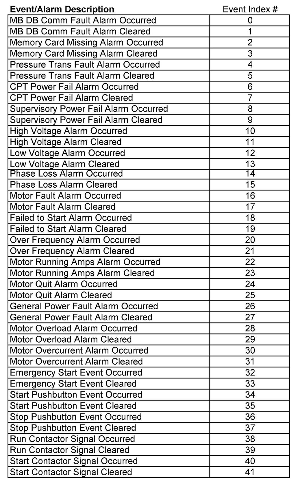
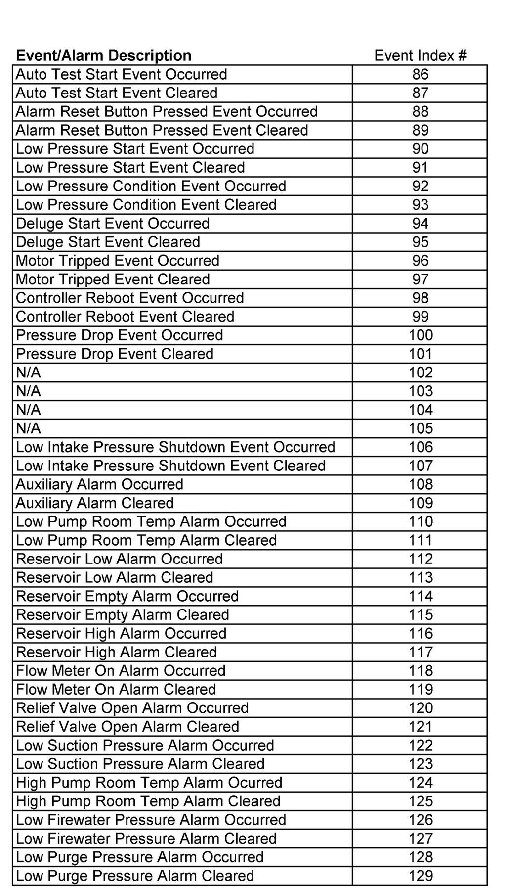
21 225 USER PREFERENCES Load Aux alarms from SD memory card [ No] 226 USER PREFERENCES Pressure Units Used to load auxiliary alarm configuration parameters from the SD card Used to determine the units for display of pressure [psi] 227 USER PREFERENCES Modbus Address Sets the Modbus Address when turned on via screen 228 [001] USER PREFERENCES Modbus Enabled (Disables Printer) 229 USER PREFERENCES Modbus/Printer Baud [38400] 230 USER PREFERENCES Modbus Parity Turns on the Modbus protocol via the RS485 and turns off the ASCII text output for the printer. Baud Rate for the Modbus or Printer, depending on which is selected in screen 228 Parity setting for the Modbus, either Even or Odd [Even] PART VII: EVENT LOG MESSAGES The following is a sample of the possible messages that could be recorded within either the alarm or event logs. Phase Failure Phase Failure declared when all three phases of the incoming power is present not Alarm Occurred/ within the limits set in the configuration screens. Alarm Cleared Pump Failed to Start Alarm Occurred Start Alarm Cleared Pressure Transducer Alarm Occurred/ Alarm Cleared Stop pushbutton Pressed in Pump Started / running Stopped Motor Lockout Sig Occurred Cleared Remote Start Sig Occurred Cleared Auto Test Start Occurred Alarm Reset Button Occurred Low Pressure Start Occurred Cleared Low Press Condition Occurred Cleared Deluge Start Occurred Cleared Controller Reboot Controller attempted to start pump but the pump failed to start (ie a pump run signal was never received). The reset button on the OID must be pressed to reset this alarm. The pressure signal from the pressure transducer has fallen outside normal operating range potentially indicating a problem with the transducer or its wiring. An operator pressed the Stop pushbutton. Pump was started either by an automatic means or the manual start pushbutton or it has stopped. A remote motor lockout signal was received or cleared. A remote start signal was received or cleared. An automatic pump test sequence was started by either the weekly program clock function or a user pressing the [TEST] button for 2 or more seconds A user did an alarm reset by pressing and holding the [SILENCE/RESET/ESC] button for 2 to 5 seconds. A low pressure start was attempted because of a low pressure reading from the transducer or optional pressure switch System pressure dropped below the start pressure or the optional pressure switch indicates a low pressure condition. This can be logged in all modes of operation. A deluge start signal was received and the pump has started. Power was restored to the microprocessor. Page 21 of 30
22 Occurred Pressure Drop Occurred Cleared Low Intake Pressure Shutdown Occurred Shutdown Cleared Auxiliary Alarm Occurred Cleared If setpoint #204 is set to yes, this event gets recorded when the system pressure drops below the setting in setpoint #205. If the low intake shutdown option is enabled in setpoint #119, a low suction signal will stop the pump. Indicates one of the aux alarms occurred as programmed in the user programs and was set to record in the event or alarm log but the text message assigned was 0. See Aux Alarm Text List Messages below for possible auxiliary alarm messages. Page 22 of 30
23 PART VIII: SD CARD FILE FORMAT. The controller is equipped with an SD (Secure Digital) memory card on the motherboard to store the Pressure log, Event log, Operators Manual in PDF format, Auxiliary Alarm configuration information and the controller drawings in PDF format. The SD card is located on the right hand edge of the motherboard and is removed by pressing in on the right edge of the card to release from the card holder. When the SD card is removed, data is still being recorded on temporary flash memory on the motherboard. Once the card is replaced, the stored data will be written back to the SD Card. When the SD card is removed, the LCD display will indicate that the card is missing and that is should be replaced. If the card is not replaced within approximately 1 minute, the alarm will sound and the System Fault LED will come on. Once the SD card is replaced, the System Fault LED will go out but the Alarm Silence button must be pressed to silence the alarm horn. The data stored on the SD card is in standard ASCII text format and can be read by an computer equipped with an appropriate SD card reader. These are readily available at any electronics store. The data on the SD card is in the following format: Pressure Log: The pressure log provides a continuous pressure record for 30 days. The pressure log samples shall be time and date stamped and stored in permanent non-volatile SD memory card. The pressure log can be searched by each sample, by minute, or by hour through the OID. PressXXX.txt file Data is stored in a standard comma delimited file as follows: 07/27/07, 11:07:52, 060 Date Time Pressure Each file starting with Press contains one days worth of pressure data. Event Log: The event log will store up to 3000 of the most current events. Events.txt file Data is stored in a standard comma delimited file as follows: 07/27/07,11:09:26,Pump Failed to Start,Occurred,208,209,208 Date Time Event Action A-B Voltage B-C Voltage A-C Voltage,0000,0000,0000,096 0,003 Phase 1 Amps, Phase B Amps Phase C Amps Pressure Pump Running Text Message # Aux Alarm Text List Messages 0 Auxiliary Alarm 1 Low Pump Room Temp 2 Reservoir Low 3 Reservoir Empty 4 Reservoir High 5 Flow Meter On 6 Relief Valve Open 7 Low Suction Pressure 8 High Pump Room Temp 9 Low Firewater Press 10 Low Purge Pressure 11 Low Gear Oil Press 12 High Gear Oil Temp 13 High Vibration 14 Gas Detection 15 Emergency Power On 16 Pump Room Door Ajar List of possible internal variables used as inputs for aux alarm user programs. 30 Pump Running 31 Power Available 32 Phase Reversal 33 Motor Overload 34 Remote Start 35 Local Start 36 Pump On Demand, Fire Condition 37 System Fault 41 Pressure Transducer Fault 42 Pump Failed to Start 43 Low Intake Shutdown Alarm 44 Supervisory Power Failure 46 Low Pressure 47 Auto Weekly Test Start 48 Under Frequency 49 Over Frequency 50 Low Zone/Hi Zone Contacts 51 High Discharge Pressure 52 No Load Condition 53 High Voltage 54 Low Voltage 55 Test Mode 56 Motor Tripped Page 23 of 30


24 RS485 Port Usage For Serial Modbus RTU protocol: PART IX: MODBUS COMMUNICATION. The Modbus option on the fire pump controller boards can be enabled by disabling the printer option to the onboard RS485 port. All communications to this port will be in a 2 wire RS485 format. 255 controllers can communicate on a single network. The pinout cabling required for connection to the port is as follows. It is necessary to apply a terminating resistor to both ends of the network. Note-Only 50 Modbus registers can be polled at time from the controller. I/O servers must be set up accordingly. Modbus Setup From Controller Interface: From the 200 series user preference configuration screens the Modbus setting can be access from screens 220 through 223. Screen 220 is used to set the Modbus address All Modbus devices on a network must have a unique address. Screen 221 is used to enable/disable the Modbus option. If Yes is selected the Modbus will be enabled and the RS485 port can no longer be used as a printer port. Screen 222 is used to set the baud rate for the RS485 port. The baud rates possible are 2400, 4800, 9600, 19200, and bits/second. Note that the baud rate setting is for the RS485 port in general and applies for Modbus and printer usage. Screen 223 is used to set the Modbus parity. Valid selections are Even, Odd, and None. This setting must match the parity setting of all other Modbus devices on the network. Modbus Register Usage Description: The historical event and pressure logs, real time clock, and user set points can be accessed and controlled through the Modbus registers listed below. Register is a write to controller only register where commands can be entered to accomplish the following as seen in figure 1.1. Depending on the Modbus I/O server used, either the individual bits in register can be toggled or integer values can be written. Either way, the controller automatically zeros register after a valid command is received. Figure 1.1 Real Time Event Monitoring: All events listed below in figure 1.2 are real time and can be viewed in Modbus register Figure 1.2 depicts the 16 bit breakdown and cross reference. This is not to be confused with the historical event log. Page 24 of 30


25 Figure 1.2 Setting And Reading The Real Time Clock Through Modbus: Modbus registers through are real time clock read registers as seen in figure 1.3. To set the clock current values must be entered into registers through Any of these registers left to zero will result in an incorrect clock setting. Once desired clock date and time values are entered bit 0 of register must be toggled for the controller to accept the values. This can be done by setting bit 0 high or writing a 1 to register The controller will then accept the new values. Figure 1.3 Most Current And Historical Alarms and Events: The most recent event or alarm date time stamped can be viewed from Modbus registers through Register contains a number representing the most current alarm or event and if it is an occurring or clearing event. The meaning of this number can be cross referenced from figures 1.6 through 1.9. Date and time for the event or alarm are viewed in registers through See figure 1.4 for register interpretation. Page 25 of 30
26 Figure 1.4 The historical events and alarms can be viewed from Modbus registers through Here it is possible to scroll through the entire log and set the log pointer to the most current record. Register contains a number representing the actual log number entry location in the controller. Register contains a number representing the event or alarm that can be indexed using figures 1.6 through 1.9. Registers through show the date and time stamp information for the log record being pointed to. To maneuver through the log: Toggling bit 3 or writing an 8 to register will increment the log by one entry. Toggling bit 4 or writing a 16 to register will decrement the log by one entry. Toggling bit 7 or writing a 128 to register will set the log to view the most current log entry. It is recommended to set the log to the most current entry before scrolling. Upon doing this the historical log should show the same data from registers in Figure 1.4. When scrolling, it is possible to move forward and backward through roughly a full weeks worth of data. Figure 1.5 Page 26 of 30

27 Figure 1.6 Figure 1.7 Page 27 of 30

28 Figure 1.8 Figure 1.9 Page 28 of 30
Fire Pump Controller. For Electric Motor Driven Fire Pumps. Wye Delta Reduced Current Types
 Fire Pump Controller For Electric Motor Driven Fire Pumps Wye Delta Reduced Current Types Series MP430 and Series MP435 Combined Manual and Automatic Metron Fire Pump Controllers conform to the latest
MANUAL FOR MODEL FD4 FIRE PUMP CONTROLLERS
 MANUAL FOR MODEL FD4 FIRE PUMP CONTROLLERS Firmware version 5.02 This manual provides General Information, Installation, Operation, Maintenance and System Set-Up Information for METRON Model FD-4 Engine
Across-the-Line SERIES MP300 Combined Manual and Automatic
 Across-the-Line SERIES MP300 Combined Manual and Automatic Metron Fire Pump Controllers conform to the latest requirements of National Fire Protection Association s Standard for Centrifugal Fire Pumps
Soft Start Series MP700 Solid State, Reduced Voltage
 Metron Fire Pump Controls and Accessories Soft Start Series MP700 Solid State, Reduced Voltage Metron Fire Pump Controllers conform to the latest requirements of National Fire Protection Association s
Variable Frequency Drive SERIES MP800 VFD
 Metron Fire Pump Controls and Accessories Variable Frequency Drive SERIES MP800 VFD Metron Fire Pump Controllers conform to the latest requirements of National Fire Protection Association s Standard for
MPT Electric Fire Pump Controller
 Setup and Operating Instructions MPT Electric Fire Pump Controller This manual provides general information, installation, operation, maintenance, and system setup information for Metron MPT Electric Fire
MPT Electric Fire Pump Controller
 MPT Electric Fire Pump Controller Alarm Messages and Guide This manual provides alarm descriptions, troubleshooting steps, and alarm set point configuration information for Metron MPT Fire Pump Controllers
ModSync Sequencing System Installation & Operation Manual. For use with Fulton Steam Boilers.
 ModSync Sequencing System Installation & Operation Manual For use with Fulton Steam Boilers. Revision 3.0 8/21/2008 - 2 - Table of Contents Introduction Page 4 Features Page 4 Sequence of Operation Page
Transfer Switch Features
 1-1 Product Description The Automatic Transfer Switch Option may be added to any FD type Fire Pump Controller whenever automatic transfer from normal to alternate power is required. The automatic Transfer
User s Manual. TIGER S EYE E-Series Mark V Jockey. TIGERFLOW Systems, Inc Mint Way Dallas, Texas
 User s Manual TIGER S EYE E-Series Mark V Jockey TIGERFLOW Systems, Inc. 4034 Mint Way Dallas, Texas 75237 214-337-8780 www.tigerflow.com TABLE OF CONTENTS Introduction... 4 Sequence of Operation... 5
Replaceable LED modules. Sleep or unattended mode. Auto-silence and auto-acknowledge
 Replaceable LED modules 11 Alarm Sequences as per ISA-18.1 standard Each channel/window fully field programmable RS232 or RS485 MODBUS-RTU communication Repeat relay for each window and multifunction relays
La Marche Manufacturing Company Option 46 Series. Digital Combined Accessory Package. Installation and Operation Manual
 La Marche Manufacturing Company www.lamarchemfg.com Option 46 Series Digital Combined Accessory Package Installation and Operation Manual This manual is subject to change without notice. You may obtain
Transfer Switch Features
 1-1 Product Description The Automatic Transfer Option may be added to any FD type Fire Pump Controller whenever automatic transfer from normal to alternate power is required. The automatic Transfer and
CONTROL PANEL INTERFACE ACTIVATE THE GENERATOR DISPLAY INTERFACE MENUS. Control Panel USING THE AUTO/OFF/MANUAL SWITCH
 CONTROL PANEL INTERFACE USING THE AUTO/OFF/MANUAL SWITCH With the switch set to AUTO, the engine may crank and start at any time without warning. Such automatic starting occurs when utility power source
EATON LMR Plus Electric Fire Pump Controllers
 O & M Manual IM05805020K EATON LMR Plus Description Page 1. INTRODUCTION... 3 2. INSTALLATION AND ELECTRICAL CONNECTIONS... 3 3. HARDWARE DESCRIPTION... 4 4. OPERATION...7 5. PROGRAMMING... 8 6. HISTORY,
Model VPS + VPU Pressure Limiting (VFD) Electric Fire Pump Controller with Soft Start Bypass with Automatic Power Transfer Switch
 Electric Fire Pump Controller with Soft Start Bypass with Automatic Power Transfer Switch") Project: Customer: Engineer: Pump Manufacturer: Technical Data Submittal Document Model VPS + VPU Pressure Limiting (VFD) with Soft Start Bypass with Automatic Transfer Switch Contents: Data Sheets Dimensional
Project: Customer: Engineer: Pump Manufacturer: Technical Data Submittal Document Model VPS + VPU Pressure Limiting (VFD) with Soft Start Bypass with Automatic Transfer Switch Contents: Data Sheets Dimensional
LMR Electric Fire Pump Controllers Features
 1-1 Printer / Recorder The industrial grade thermal printer is housed in a rugged steel enclosure within the controller. The on/off switch, feed and reset buttons are front accessible. A bi-color status
Microprocessor Based Wye-Delta Reduced Current Type Starting
 Metron Fire Pump Controls and Accessories NEW Microprocessor Based Wye-Delta Reduced Current Type Starting PRODUCT PILOT SERIES MPT430TS (Open Transition) - MPT435TS (Closed Transition) ONLY 32 WIDE WITH
AGC 200 Advanced Gen-set Controller OPERATOR S MANUAL
 Advanced Gen-set Controller OPERATOR S MANUAL Display readings Push-button functions Alarm handling Log list Document no.: 4189340607A SW version 3.5X.X or later Table of contents 1. ABOUT THIS DOCUMENT...3
FDF Foam Pump Controllers Features
 FDF100 Diesel Engine Foam Pump Controllers 1-1 Product Description The FDF Series of Foam Pump Controllers are designed for use with foam concentrate injection, foam transfer and water mist systems for
ZX1e ZX2e ZX5e. Document No Issue 01 user manual
 ZX1e ZX2e ZX5e Document No. 996-130 Issue 01 user manual MORLEY-IAS ZX2E/ZX5E Fire Alarm Control Panels Table of Contents 1 INTRODUCTION... 4 1.1 NOTICE... 4 1.2 WARNINGS AND CAUTIONS... 4 1.3 NATIONAL
LMR Electric Fire Pump Controllers Features
 1-1 Printer / Recorder The industrial grade thermal printer is housed in a rugged steel enclosure within the controller. The on/off switch, feed and reset buttons are front accessible. A bi-color status
Drawing Submittal Package
 Project: Customer: Engineer: Pump Manufacturer: Drawing Submittal Package Model GPL + GLU Limited Service Full Voltage Across the Line Start Electric Pump Controller with Automatic Power Transfer Switch
DIESEL Engine Fire Pump Controllers Features. FD120 Diesel Engine Controllers
 DIESEL Engine Fire Pump Controllers Features FD120 Diesel Engine Controllers 1-1 March 2013 Diesel Product Description The DIESEL Plus Fire Pump Controllers from Eaton Corporation are designed to control
Customer Connection Terminals Connection terminals for external customer connections, are located at the top of the Power I/O board.
 Must Be Installed Per Applicable Code and Manufacturers Recommendations Electric Fire Pump Controllers Features 1-1 FD80 Reduced Voltage - Wye Delta (Star-Delta) Closed Transition Power I/O Board Transformers
Power Flame Incorporated
 Power Flame Incorporated SUGGESTED SPECIFICATION FOR MODEL NVC ULTRA LOW NOx GAS BURNERS SUB 9 PPM NOx THE POWER TO MANAGE ENERGY 2001 South 21st Street, Parsons, Kansas 67357 Telephone: 620-421-0480,
Project: Customer: Engineer: Pump Manufacturer: Model GPY + GPU. with Automatic Power Transfer Switch
 Project: Customer: Engineer: Pump Manufacturer: Model GPY + GPU with Automatic Power Transfer Switch Contents: NOTE: The drawings included in this package are for controllers covered under our standard
MASTER JOCKEY PUMP CONTROLLER. Model JPCE INSTRUCTION MANUAL. C 2018 Master Control Systems, Inc
 MASTER JOCKEY PUMP CONTROLLER Model JPCE INSTRUCTION MANUAL C 2018 Master Control Systems, Inc TABLE OF CONTENTS Important Safety Information. Page 3 General Description and Installation.. Page 4 Model
Spa Touch Control Panel with 2000, 2100 controllers. (Spa Owner s Manual insert)
") Spa Touch Control Panel with 2000, 2100 controllers (Spa Owner s Manual insert) P.N. 7876B February 11, 2015 For Spas equipped with BP2000, BP2100 controllers and Spa Touch panel. Spa Touch Control Panel
Spa Touch Control Panel with 2000, 2100 controllers (Spa Owner s Manual insert) P.N. 7876B February 11, 2015 For Spas equipped with BP2000, BP2100 controllers and Spa Touch panel. Spa Touch Control Panel
MYRIAD TRIPLEX PUMP CONTROLLER INSTRUCTION MANUAL
 MYRIAD TRIPLEX PUMP CONTROLLER INSTRUCTION MANUAL MYRIAD TPC VISIT OUR WEBSITE SIGMACONTROLS.COM MYRIADI&O062705 2 TABLE OF CONTENTS INTRODUCTION 3 Ordering Information Specifications Features WIRING 7,8
21-light Remote Annunciator. Owner s Manual
 21-light Remote Annunciator Owner s Manual Annunciator Description... Inside Font Cover Detailed Specifications... 1 Environmental Specifications... 1 Power Supply Requirements... 1 Communication With
Control Panel. 1.0 GENERAL SCOPE OF WORK Introduction... 2
 Architectural & Engineering Specifications Control Panel 1.0 GENERAL... 2 1.1 SCOPE OF WORK... 2 1.1.1 Introduction... 2 1.2 GENERAL CONDITIONS... 2 1.2.1 After-Sales Support... 2 1.2.2 Quality assurance...
A-Tech-20 Advanced Microprocessor Controller
 A-Tech-20 Controller Operation Manual (04/02/01) 1 C Y B E R A i R Product Division A-Tech-20 Advanced Microprocessor Controller Operations Manual Project: SATS Model: SATS SN: SATS JN: Unit Tags: REVISION
Spa Touch Control Panel with BP2100, BP6013 spa controllers. (Spa Owner s Manual insert)
") Spa Touch Control Panel with BP2100, BP6013 spa controllers. (Spa Owner s Manual insert) P.N. 7876C (export) February 12, 2015 For Spas equipped with BP2100, BP6013 controllers and Spa Touch panel. Spa
Spa Touch Control Panel with BP2100, BP6013 spa controllers. (Spa Owner s Manual insert) P.N. 7876C (export) February 12, 2015 For Spas equipped with BP2100, BP6013 controllers and Spa Touch panel. Spa
FD30 Full Voltage - Across the Line July 2011
 Must Be Installed Per Applicable Code and Manufacturers Recommendations Electric Fire Pump Controllers Features 1-1 FD30 Full Voltage - Across the Line July 2011 Power I/O Board Transformers Incoming line
TECHNICAL MANUAL CVM 20 C 5005 CV/04-99 GB
 Summary 1 CONNECTIONS... 3 1.1 TEMPERATURE PROBES...3 1.2 LOW VOLTAGE DIGITAL INPUTS...3 1.3 LIVE DIGITAL INPUTS...4 1.4 RELAY OUTPUTS...5 2 POWER SUPPLY... 6 3 SERIAL CONNECTIONS... 6 4 SOFTWARE... 7
PROCESS & TEMPERATURE UNIVERSAL INPUT DIGITAL METERS
 PROCESS & TEMPERATURE UNIVERSAL INPUT DIGITAL METERS NOVA PD56 Series Thermocouple, RTD, & Process Inputs Universal Power Supply 1-24 VAC Up to 3 Alarm Relays Retransmitting 4-2 ma Output Input Max/Min
1.1 REFERENCES.1 American National Standards Institute/National Fire Protection Association (ANSI/NFPA).1 ANSI/NFPA 20, Centrifugal Fire Pumps.
.1 ANSI/NFPA 20, Centrifugal Fire Pumps.") Issued 2006/08/01 Section 13920 Packaged Fire Pumps and Controllers Page 1 of 7 PART 1 GENERAL 1.1 REFERENCES.1 American National Standards Institute/National Fire Protection Association (ANSI/NFPA).1
Issued 2006/08/01 Section 13920 Packaged Fire Pumps and Controllers Page 1 of 7 PART 1 GENERAL 1.1 REFERENCES.1 American National Standards Institute/National Fire Protection Association (ANSI/NFPA).1
Operation Manual. Programmable Logic Controller
 Operation Manual Programmable Logic Controller Part No. 9983-0000-E01 / January 2018 OPERATION MANUAL TABLE OF CONTENTS CUSTOMER SERVICE 3 CONTACT INFORMATION 3 ORDER INFORMATION 3 INTRODUCTION 4 THE PROCESS
Process & TeMPerATUre UniversAl input DigiTAl MeTers
 Process & TeMPerATUre UniversAl input DigiTAl MeTers nova PD56 series Thermocouple, rtd, & Process inputs Universal Power supply 1-24 va c Up to 3 Alarm relays retransmitting 4-2 ma output input Max/Min
Powerohm Resistors Digital HRG System
 Installation and Operating Instructions Powerohm Resistors Digital HRG System This manual provides general information, installation, operation, maintenance, and system setup information for the Powerohm
MASTER PRESSRE MAINTANENCE CONTROLLER. Models PMCE INSTRUCTION MANUAL. C 2018 Master Control Systems, Inc
 MASTER PRESSRE MAINTANENCE CONTROLLER Models PMCE INSTRUCTION MANUAL C 2018 Master Control Systems, Inc TABLE OF CONTENTS Important Safety Information. Page 3 General Description and Installation.. Page
Drawing Submittal Package
 Project: Customer: Engineer: Pump Manufacturer: Drawing Submittal Package Model GPL + GLU Limited Service Full Voltage Across the Line Start Electric Pump Controller with Automatic Power Transfer Switch
Lift Station Level Controller
 Lift Station Level Controller Installation and Operation Manual 1 California Motor Controls, Inc. Benicia, CA Table of Contents 1. Features Product Overview... 4-6 Access Security... 7 Optional Features...
Tempered Water Logic Control OPERATION l TROUBLE SHOOTING
 Tempered Water Logic Control OPERATION l TROUBLE SHOOTING English For MPE Multiple Chiller Units Control Panel TEMPERED WATER SYSTEMS L-2199 Rev. 20080223 Revision: L-2199 20101104 *** IMPORTANT NOTICE
Fire Pump Controllers Medium Voltage Controllers
 Fire Pump Controllers Medium Voltage Controllers Medium Voltage Controllers 1.5 Medium Voltage Fire Pump Controllers FDM Medium Voltage... Part Number / Options Selection Guide... Product Specifications
Spectron LSN (Life Safety Network) Suggested Specifications
 Suggested Specifications") 1. General 1.1 Scope A Dual-Lite Spectron LSN (Life Safety Network) Series Inverter System shall be furnished to provide a reliable source of power, and shall operate during a utility line deficiency without
1. General 1.1 Scope A Dual-Lite Spectron LSN (Life Safety Network) Series Inverter System shall be furnished to provide a reliable source of power, and shall operate during a utility line deficiency without
D8024, D9024, D10024 Analog Fire Alarm Control Panels Programming Guide
 System Reset Trou ble Silence Ala rm Silence Manual Ala rm ENTER NO YES Letters Numb ers Keyword Radionics System Reset Trouble Silence Alarm Silence Manual Alarm ENTER NO YES Le ters Numbers Keyw ord
CELLTROL II BIOREACTOR CONTROL SYSTEM OPERATIONS MANUAL
 Operation Manual Celltrol II Bioreactor Control System Page 1 of 33 Table of Contents 1) Introduction... 3 1.1) Scope of Document... 3 1.2) Control System Overview... 3 1.3) Introduction to Celltrol II...
Product Manual SZ1009
 Product Manual SZ1009 Conventional Heating & Cooling Thermostats with Heat Pump Mode Communicating Thermostats Description The SZ1009 is a microprocessor-based mable thermostats designed for conventional
SCC Inc. Master Panel. Specifications. Document No. TS 2010 February 11, Product Description. Sample Specification
 February 11, 2019 Master Panel Product Description The Master Panel shall provide lead/lag control and time based, automatic rotation of up to eight (8) boilers, when used in conjunction with LMV3 or LMV5
PEGAsys. Multi-Loop Intelligent Suppression Control System FEATURES DESCRIPTION. Effective: March 2007 K
 PEGAsys Multi-Loop Intelligent Suppression Control System A UTC Fire & Security Company Effective: March 2007 K-76-028 FEATURES UL Listed CSFM Approved MEA Approved Peer-to-Peer Networking (to 32 nodes)
Model VPS Pressure Limiting (VFD) Electric Fire Pump Controller with Soft Start Bypass
 Electric Fire Pump Controller with Soft Start Bypass") Project: Customer: Engineer: Pump Manufacturer: Submittal Document Model VPS Pressure Limiting (VFD) with Soft Start Bypass Contents: Data Sheets Dimensional Data Wiring Schematics Field Connections Note:
Project: Customer: Engineer: Pump Manufacturer: Submittal Document Model VPS Pressure Limiting (VFD) with Soft Start Bypass Contents: Data Sheets Dimensional Data Wiring Schematics Field Connections Note:
Fire Command Keypad. XR5 User s Guide
 Fire Command Keypad XR5 User s Guide Silencing an Alarm While the fire alarm horns, strobes, or sirens are sounding use one of the following methods to silence the alarm depending on which type of keypad
Fire Pump Controllers Foam (Additive) Controllers
 Controllers") Fire Pump Controllers Foam (Additive) Controllers Diesel Additive (Foam) Pump Controllers 1.4 Foam (Additive) Fire Pump Controllers FDF20 Foam (Additive) - Limited Service... FDF30 Foam (Additive) - Across-the-Line...
Fire Pump Controllers Foam (Additive) Controllers Diesel Additive (Foam) Pump Controllers 1.4 Foam (Additive) Fire Pump Controllers FDF20 Foam (Additive) - Limited Service... FDF30 Foam (Additive) - Across-the-Line...
GLD-30 Gas Leak Detector
 GLD-30 Gas Leak Detector Installation, Operation & Maintenance General: The Archer Instruments GLD-30 is an ambient air monitor, used to detect the presence of a target gas (or gases) and to alert operators
INSTALLATION INSTRUCTIONS
 TT-1343 5/06b INSTALLATION INSTRUCTIONS Original Issue Date: 8/03 Model: Automatic Transfer Switches Equipped with Series 1000 Programmable Controller Market: ATS Subject: Remote Annunciator Kits GM28938-KP1,
Technical Data Submittal Document
 Project: Customer: Engineer: Pump Manufacturer: Technical Data Submittal Document Model GPL + GLU Limted Service Full Voltage Across the Line Start Electric Fire Pump Controller Contents: Data Sheets Dimensional
Control/Communicator
 Architectural & Engineering Specifications Control/Communicator 1.0 GENERAL... 2 1.1 SCOPE OF WORK... 2 1.1.1 Introduction... 2 1.2 GENERAL CONDITIONS... 2 1.2.1 After-Sales Support... 2 1.2.2 Quality
Carbon Monoxide Transmitter
 Introduction The CO Transmitter uses an electrochemical sensor to monitor the carbon monoxide level and outputs a field-selectable 4-20 ma or voltage signal. The voltage signal may also be set to 0-5 or
ORP (mv) Controller Model: ORP-XP2. UP DOWN ENTER Time & Date Main Menu Alarm Reset
 Controller Model: ORP-XP2. UP DOWN ENTER Time & Date Main Menu Alarm Reset") Instruction Manual ORP (mv) Controller Model: ORP-XP2 Power Control Alarm Comms UP DOWN ENTER Time & Date Main Menu Alarm Reset Supplied by: Convergent Water Controls Pty Ltd 2/4 Huntley Street, PO Box
Instruction Manual ORP (mv) Controller Model: ORP-XP2 Power Control Alarm Comms UP DOWN ENTER Time & Date Main Menu Alarm Reset Supplied by: Convergent Water Controls Pty Ltd 2/4 Huntley Street, PO Box
Xtralis VESDA LCD Programmer Quick Reference Guide
 Xtralis VESDA LCD Programmer Quick Guide Xtralis VESDA VLP Xtralis VESDA VLS Xtralis VESDA VLC Scope of this Manual This manual is to be used as a quick reference guide to perform the initial detector
Installation, Operation and Maintenance Manual. RQ Series. Mold Temperature Control Units 0.75 to 7.5 hp and 0 to 24 kw
 Installation, Operation and Maintenance Manual RQ Series Mold Temperature Control Units 0.75 to 7.5 hp and 0 to 24 kw Copyright 2010 Thermal Care Inc. Table of Contents Foreward... 3 Safety Guidelines...
FT60 Reduced Voltage - Autotransformer
 1-1 Product Description The Automatic Transfer Switch Option may be added to any FD type Fire Pump Controller whenever automatic transfer from normal to alternate power is required. The automatic Transfer
Safety & Installation Instructions
 Model 8800 Universal Communicating Thermostat Safety & Installation Instructions READ AND SAVE THESE INSTRUCTIONS Table of contents Installation Installation location recommendations... 2 Thermostat mounting...
ESSEX ENGINEERING CORPORATION
 WATER/WASTEWATER TREATMENT CONTROL SYSTEMS AND SUBSYSTEMS 2000 SERIES CONTROL SYSTEMS: 2000 series are for surface mounting inside a control cabinet Model 2024 Electronic Alternator Duplex (two pump) pump
PWGSC Ontario MULTIPLEX FIRE ALARM SYSTEM Sect Region Project Page 1 Number R
 Region Project Page 1 PART 1 - GENERAL 1.1 REFERENCES.1 CAN/ULC-S524-2006, Standard for the Installation of Fire Alarm Systems..2 CAN/ULC-S525-2007, Audible Signal Device for Fire Alarm Systems..3 CAN/ULC-S526-2007,
UltraLITE Model ELU Centralized Emergency Lighting Inverter 4.2 KW- 5 KW
 12/23/16 Rev 9 UltraLITE Model ELU General Specification 4.2 KW to 5 KW UltraLITE Model ELU Centralized Emergency Lighting Inverter 4.2 KW- 5 KW 1.0 General General Specification This specification describes
FT20 Full Voltage - Limited Service. Electrically and Mechanically
 LMR PLUS Electric Fire Pump Controllers with Transfer Switch FT20 Full Voltage - Limited Service 1-1 May 2014 Product Description The Automatic Transfer Switch Option may be added to any FD type Fire Pump
Dryer Master Inc. Dryer Master AM 3. Product Manual
 Dryer Master Inc. Dryer Master AM 3 Revision 1.0 July, 2008 Revision 1.2 February, 2009 Revision 1.3 March, 2009 Revision 1.4 September, 2013 Prepared by: Dryer Master Inc. Dryer Master Inc 2008, 2009,
HRX Technical Manual. Version 1.2
 HRX 5000 Technical Manual Version 1.2 Contents: Specification...2 Connectors...5 RS-485 Network Connectors (J6 and J7)...5 RS-232 to Printer (J19)...6 RS-232 to PC (J8)...7 TCP/IP...8 Power (J21)...9 Fire
Type 8001 PRIME MOVER CONTROLS INC. ALARM ANNUNCIATOR TYPE8001 FEATURES SB 8001B
 PRODUCT BULLETIN SB 8001B Type 8001 ALARM ANNUNCIATOR TYPE8001 FEATURES 16 or 32 alarm points per flush mount enclosure Displays are backlit with long life LEDs and engraved to suit Dimmer controls built
OPERATOR S MANUAL MR-2100/2200. Fire Alarm Control Unit. Revision 0 Document #: LT-2002
 MR-2100/2200 Fire Alarm Control Unit OPERATOR S MANUAL Revision 0 Document #: LT-2002 WARNING: This manual contains information on limitations regarding product use and function and information on the
Tri-Stack Smart System
 Tri-Stack Smart System TM Notes & Warnings - The protection provided by this equipment may be impaired if it is not used in the manner specified herein. - Ensure all wiring meets applicable national and
STEAMPAK Series BurnerPAK BMS Burner Management Systems
 BurnerPAK BMS Burner Management Systems Sequence of operation, ignition and control of burners Meets NFPA 85 safety standard MFT alarming with manual reset, first-out indication Optional enhanced alarming
Oakton TEMP 9500 Advanced Multiparameter Controller
 Oakton TEMP 9500 Advanced Multiparameter Controller Models: 89800-03 & 89800-04 Oakton Instruments 625 E Bunker Ct. Vernon Hills, IL 60061, USA 1-888-4OAKTON (1-888-462-5866) info@4oakton.com Contents
Technical Data Submittal Documents
 Project: Customer: Engineer: Pump Manufacturer: Technical Data Submittal Documents Model PD - FM Diesel Engine Driven Fire Pump Controller Contents: Data Sheets Dimensional Data Wiring Schematics Field
ID2000. operating manual
 ID2000 operating manual 997-434-000-2, Issue 2 Contents ID2000 Series Operating Manual Contents 1 Introduction 1 1.1 Associated Documents 1 1.2 The ID2000 Panels 1 1.3 Cleaning 2 2 Panel Controls and Indicators
Dryer Master DM510 Commissioning Guide
 COMMISSIONING GUIDE Dryer Master DM510 Dryer Moisture Systems Inc. 640 Superior Drive Waterloo, Ontario Phone 519.725.4700 Fax 519.885.4300 USA & Canada Toll Free 1-888-318-0009 E-mail: info@dryermaster.com
CONsOlIDATOR 4 & 8. MulTI- C h ANNEl CONTROllERs. ConsoliDator 4 Model PD940 ConsoliDator 4 Features. ConsoliDator 8 Features.
 CONsOlIDATOR 4 & 8 MulTI- C h ANNEl CONTROllERs ConsoliDator 4 Model PD940 ConsoliDator 4 Features Four 4-20 Four 4-20 Outputs ConsoliDator 8 Features Eight 4-20 Two 4-20 Outputs Common Features Four Pulse
Product Manual SZ1145
 Product Manual SZ114 General Purpose Monitor Communicating Controls Description The SZ114 is a microprocessor-based monitoring and alarm interface designed to monitor up to four 1000 Ω platinum temperature
DGC-1000 DIGITAL GENSET CONTROLLER
 DGC-1000 DIGITAL GENSET CONTROLLER Basler Electric s Digital Genset Controller (DGC-1000) offers a low cost microprocessor based integrated alternative for small to medium sized genset control and monitoring.
AD-1272 Advanced Thermal Dispersion Probe Airflow Measuring System
 AD-1272 Advanced Thermal Dispersion Probe Airflow Measuring System Technical Bulletin AD-1272 Code No. LIT-12012477 Issued December 2017 Refer to the QuickLIT website for the most up-to-date version of
RANGER 8600 DOWNLOADABLE CONTROL COMMUNICATOR INSTALLATION MANUAL
 RANGER 8600 DOWNLOADABLE CONTROL COMMUNICATOR INSTALLATION MANUAL TABLE OF CONTENTS GENERAL DESCRIPTION... 2 STANDARD AND OPTIONAL PARTS LIST... 2 PARTS DIAGRAM... 3 TERMINAL DRAWING AND SPECIAL NOTES...
CARD ACCESS CONTROL SYSTEM
 SECTION 13851 CARD ACCESS CONTROL SYSTEM PART 1 GENERAL 1.01 SUMMARY A. Section Includes: A complete, operable, tested, integrated proximity access control system, to operate on a proximity principle where
SERIES 3000 INTELLIGENT FIRE ALARM CONTROL PANEL ENGINEERING PROGRAMING MANUAL TABLE OF CONTENTS.. 1 INTRODUCTION.. 3 SYSTEM POWER UP.
 SERIES 3000 INTELLIGENT FIRE ALARM CONTROL PANEL ENGINEERING PROGRAMING MANUAL TABLE OF CONTENTS.. 1 INTRODUCTION.. 3 SYSTEM POWER UP. 3 1 PANEL SWITCHES. 3 FIRE ZONE LAMP 4 OTHER LAMPS 4 MULTIPLEX OUTPUT.
PowerWizard. Level 1.0 & Level 2.0 Control Systems Training
 PowerWizard Level 1.0 & Level 2.0 Control Systems Training New Systems Current Systems Systems Comparison Level 1 Level 2 Level 3 Level 4 PowerWizard Level 3.0 PowerWizard Level 4.0 Overview Common parts
NS (A) ECN
 ECN") Installation and Operation Instructions Mark IIXG Diesel Engine Fire Pump Controllers FTA00 NS00-50(A) ECN 237793 Table of Contents INTRODUCTION... MOUNTING CONTROLLER... Wall Mount... - 2 Floor/Base Plate
Installation and Operation Instructions Mark IIXG Diesel Engine Fire Pump Controllers FTA00 NS00-50(A) ECN 237793 Table of Contents INTRODUCTION... MOUNTING CONTROLLER... Wall Mount... - 2 Floor/Base Plate
Modular Standard HP Chiller 1/4 screw compressor with Carel driver
 Program for pco¹ pco 2 and pcoc Modular Standard HP Chiller 1/4 screw compressor with Carel driver Manual version 1.0 25 September 2003 Program code: FLSTDmMSDE Do we want you to save you time and money?
Application, Installation, Operation & Maintenance Manual
 APPROVED BY:JBJ PRESCIENT III FIRE ALARM & GAS EXTINGUISHING CONTROL PANEL Application, Installation, Operation & Maintenance Manual PAGE 1 of 43 CONTENTS 1. INTRODUCTION... 3 2. GENERAL DESCRIPTION...
Specification/ Data Sheet
 Specification/ Data Sheet TRITON RP Agent Release Control Panel FEATURES Agent Release Control Panel designed specifically for suppression release operation with: Four initiating device circuits (IDCs)
SCAN200E USER S MANUAL
 SCAN200E USER S MANUAL Code No. 2071 1052 rev. 1.4 Code No. 2071 1052 Rev. 1.4 Page 2/16 SCAN200E User s Manual Foreword This manual is for SCAN200E Controller running software version 2.03 or later. We
DIESEL Engine Fire Pump Controllers Features
 September 007 DIESEL Engine Fire Pump Controllers Features FD0 Diesel Engine Controllers 1-1 Printer / Recorder The industrial grade thermal printer is housed in a rugged steel enclosure within the controller.
WITH POWER TRANSFER SWITCH STANDARD SUBMITTAL PACKAGE
 WITH POWER TRANSFER SWITCH STANDARD SUBMITTAL PACKAGE SBP1000-61 FTA1000 Full Voltage Starting Electric Fire Pump Controllers Product Description Description Firetrol FTA1000 Full Voltage Fire Pump Controllers
ACSI AO ELECTRIC LATCH RETRACTION CONTROLLER INSTALLATION INSTRUCTIONS I.D. 1089, REV. F
 II 1400-2 ACSI 1406-04-AO ELECTRIC LATCH RETRACTION CONTROLLER INSTALLATION INSTRUCTIONS I.D. 1089, REV. F INSTALLATION Transformer Model BE31763001 by Basler Electric, Transformer Model 2010028 by Galaxy
TWLC - Tempered Water Logic Controller. The Intelligent Control
 TWLC - Tempered Water Logic Controller The Intelligent Control Chiller Controls Features: Up to six (6) stages: individual board for each stage maximizes redundancy. Menu driven access and programming.
Installation and Operation Manual
 SENTRY Protect Plus QUADPLEX PANEL Installation and Operation Manual For Hardwired Pumps Environment e Corporation Table of Contents 1 Overview...3 2 Sentry Protect Plus Quadplex Menu Flowchart...4 3 Wiring
DIESEL Engine Fire Pump Controllers Features
 1-1 Product Description The FD100 Diesel Engine Controller is designed to control and monitor 12 or 24 volt, diesel fire pump engines. All models are listed by UL and ULC, and approved by Factory Mutual
A36D/TPSD Modbus RTU (Serial) SCADA INTERFACE INSTRUCTIONS
 SCADA INTERFACE INSTRUCTIONS") SCADA INTERFACE INSTRUCTIONS - OPTION 21S - FOR A36D/TPSD SYSTEMS with option 500 and 550. A36D/TPSD Modbus RTU (Serial) SCADA INTERFACE OPTION 21S INSTRUCTIONS This manual is valid for A36D/TPSD Chargers
SCADA INTERFACE INSTRUCTIONS - OPTION 21S - FOR A36D/TPSD SYSTEMS with option 500 and 550. A36D/TPSD Modbus RTU (Serial) SCADA INTERFACE OPTION 21S INSTRUCTIONS This manual is valid for A36D/TPSD Chargers
PHYSICAL FACILITIES Consultant s Handbook Specifications Division 21 Fire Suppression 3000 Fire Pumps
 Note: The A/E must choose all design values in brackets below before using in project specifications 1 General 1.1 Provide UL listed and FM approved fire pump complete with pump, driver, controller and