STATE OF NORTH CAROLINA
|
|
|
- Preston Austin
- 5 years ago
- Views:
Transcription
1 STATE OF NORTH CAROLINA DEPARTMENT OF ADMINISTRATION STATE CONSTRUCTION OFFICE Fire Alarm GUIDELINES AND POLICIES 2011
2 Instruction to Designers: 1. Designers for State projects involving fire alarm systems shall use and follow the Department of Administration document Fire Alarm Guidelines and Policies only for the purpose of preparing the designer s plans and specifications for the specific project in their contract. The document is not written in contractual language for bidding purposes and/or contract enforcement. Therefore the designer is not to insert the document as is into the specifications. (The Designers can copy from the Guidelines applicable sections and paste to project written specifications.) 2. It is the Engineer s responsibility to read and comply with all relevant criteria in the SCO Fire Alarm Guidelines and Policies. These Guidelines and others are available at the State Construction Office web site Any design noncompliance with the Fire Alarm Guidelines and Policies resulting in a change order shall be the responsibility of the designer. 3. Clarification: When expressions are shown between two forward slanted lines, the Designer is to select the most appropriate expression. Example: //Provide photoelectric smoke detection, ionization smoke detection and rate of rise thermal detection.// - 2 -
3 TABLE OF CONTENTS A. General Fire Alarm System in State Owned Facilities Document Specific Furnishing, Installation & Connection of the System Applicable Codes Fire Alarm Control Panel Secondary Power Quality Assurance Code and Standards Definition Submittals B. Part 2- Products Fire Alarm Control Panel Alarm Appliances Initiating Devices Miscellaneous System items Wiring C. Part 3- Execution Fire Alarm System Fire Alarm Control Equipment Installation Addressable Interface Modules (control and monitor Modules) Surge Protection Riser Design AC Power Conduit and Wiring
4 Notification devices Detectors Duct Mounted Smoke Detectors Linear Beam Smoke Detectors Printer Air Handler Unit (AHU) Shutdown Annunciator Alarm Verification for Smoke Detectors Emergency Voice/Alarm Communication Remote Alarm Transmission Requirements Automatic Smoke door and Automatic Lock Requirements Sprinkler System Monitoring Kitchen Exhaust Hood Extinguishing Systems Fire Alarm System Installation and Configuration Fire and Life Safety Criteria for Doors Controlled by Fire Alarm System System Documentation, Training, and Maintenance Spare Parts System Testing & Certification Pre-Final Inspection Final Inspection APPENDIX Table 1 Applications Matrix for Selection Detection Devices Fire Alarm System Symbols FA- 01 Fire Alarm Riser (Example) FA-02 Fire Alarm Riser Notes (Example) FA-03 Fire Alarm Matrix (Example) FA-04 Transient Arrestor Installation Detail FA
5 Part 1- General * 1. This document is to help assure that the fire detection and alarm systems installed in State Owned buildings are reliable, maintainable, and have a long service life. 2. This document does not constitute a complete design specification and must be edited and supplemented with project-specific requirements written by the design professional. 3. This document includes the furnishing, installation, and connection of the microprocessor controlled, intelligent reporting fire alarm equipment required to form a complete coordinated system ready for operation. It shall include, but not be limited to, alarm initiating devices, alarm notification appliances, control panels, auxiliary control devices, annunciators, power supplies, and wiring. 4. The fire alarm system shall comply with applicable provisions of the NC Building Code, NFPA 70 - National Electrical Code (NEC) and NFPA 72 -National Fire Alarm Code. The Contractor shall furnish all parts, materials, and labor customarily required or provided for a complete and operating system, in accordance with all requirements applicable, even if each needed item is not specifically shown or described in the project plans or specifications 5. The Fire Alarm Control Panel (FACP) shall be located for convenient, rapid access. When not located in a public or normally occupied area, a Remote Anunnciator (FAA) with audible-visible trouble indication is required. Consult with facility manager and the local fire official, prior to locating the FACP, FAA or printer. If there is no constantly attended station, the FACP or FAA shall be located in a lobby or a corridor adjacent to the entrance used by responding personnel. 6. Systems are to be provided with a separate and independent source of secondary power. The State does not contract for full Central Station Service (with runners), so all systems that report to a Central or Remote Supervising Station shall have a minimum of 60 hours battery power capacity, plus 5/15 minutes of full alarm load. Proprietary and other systems require 24 hours capacity plus 5/15 minutes alarm load. a) When automatic starting generator is provided, use 24 hours for battery endurance, plus the appropriate (5 or 15 minutes) alarm load. See NFPA 72. b) Most campus alarm supervising stations are normally classified as Proprietary systems. c) Most Facilities can use the State Capitol Police located in Raleigh Remote Supervising Station * If system is being installed to replace an existing system verify that the Drawings detail the scope of any demolition that may be required. Pay particular attention to items that may be reused in the new system. 7. QUALITY ASSURANCE a) Manufacturer's Qualifications: Firms regularly engaged in manufacture of fire alarm systems of types, sizes, and electrical characteristics required, and whose products are - 5 -
6 Listed and Labeled. Products of firms that do not maintain factory authorized service organization and spare parts stock are not acceptable for use on State Owned Buildings. b) Acceptable Manufacturers: Designers shall list minimum of three manufacturers. c) Installer s Qualifications: d) Company specializing in performing the work and making the final terminations and connections. Minimum of 5 years documented experience installing fire detection and alarm systems similar in size and scope to the project. Only the Installer may make program changes and must be present for the 100% test, Designer s pre-final review and Owner inspections. e) All connections to the FACP and the system's programming shall be done only by the manufacturer, or by an authorized distributor that stocks a full compliment of spare parts for the system. The technicians are required to be trained and individually certified by the manufacturer, for the FACP model/series being installed. This training and certification must have occurred within the most recent 24 months, except that a NICET Level III certification will extend this to 36 months. Copies of the certifications must be part of the Shop Drawing submittal to the Designers, prior to installation. The submittal cannot be approved without this information. 8. Codes and Standards: a) NFPA Compliance: Comply with applicable requirements of NFPA-72, National Fire Alarm Code. b) NEC Compliance: Comply with applicable requirements of NFPA-70, National Electrical Code (NEC) standards pertaining to fire alarm systems. c) Testing Laboratory Compliance: Comply with provisions of UL safety standards pertaining to fire alarm systems. Provide products and components which are Listed and Labeled. d) FM Compliance: Provide fire alarm systems and accessories which are FM approved. 9. Definitions: a) For State-owned facilities in North Carolina the AHJ for Code compliance is the NC Department of Administration State Construction Office. The AHJ for construction administration and inspection purposes is the entity that contracted for the design services, either the State Construction Office or the owning Agency, as applicable. (Fire alarm system inspection or acceptance testing may be delegated to the design engineer by contract.) b) For Community College or local government projects the AHJ is the local government entity that approves project plans, issues building permits, and inspects construction. c) Building Permits: (1) No building permit is required for construction or renovation of facilities that are funded by the State of North Carolina and located on State-owned land. However, privately-funded projects on land leased from the State (e.g., student housing) must still be submitted to local building officials for approval, permits, and inspections. Written NCDOA/SCO - 6 -
7 approval of the plans and specifications submitted for review is considered the equivalent of a building permit for State projects but that alone does not give authorization to proceed with construction. Such authorization requires written clearance from the entity that administers the contract. (2) Fire Alarm Control Panel (FACP) - Also called a Fire Alarm Control Unit (FACU) by some entities. See requirements in Part 2 (3) Remote Anunnciator (FAA) Provides LCD display with a text statement of the panel status and/or LED lamps to indicate the status of the fire alarm system. It is provided to assist fire fighters who respond to a call and to assist technicians who respond to a trouble condition. (4) Graphic Anunnciator (GA) Used to provide information regarding the status of detection, sprinkler and supervisor devices by zone and or floor of the building. 10. SUBMITTALS: a) General: Submittals shall demonstrate compliance with technical requirements by reference to each subsection of the Engineer s written specification. b) Product Data: Submittals shall provide ma draw for each device submitted and the listed minimum voltage required to operate. Panel submittal shall list voltage drop allowed for panel and for individual NAC circuits. c) Shop Drawings: (1) The fire alarm contractor shall submit complete Shop Drawings to the engineer for review, prior to performing any work. They shall clearly demonstrate compliance with the engineer s plans and specifications, which have a System Response Matrix showing the fire alarm system's actions (outputs) required for each type of alarm, supervisory, and trouble signal. Any non-compliant features must be fully described. (2) The submitted shop drawings shall show equipment, device identification numbers and locations, and connecting wiring of entire fire alarm system. Include wiring and riser diagrams. Wiring diagrams shall be based on the project floor plans, with devices and proposed conduit routing. The conductor composition for each conduit section shall be provided. The distance and route for each NAC (Notification Appliance Circuit) shall be shown. Riser diagrams shall show consecutive connections for all devices with addresses and candela and Candela ratings. (3) Engineer s approval (with or without corrections) of contractor s Shop Drawings, samples, cut sheets, etc., is for general conformance with the contract documents and design concept. It shall not relieve the contractor of responsibility for full compliance with the project plans and specifications, EXCEPT for any specific non-compliant features for which the engineer gives written authorization. d) Installation Instructions: The contractor shall submit to the engineer of record the Manufacturer's detailed installation instruction for the Fire Alarm Control Panel and all duct mounted smoke detectors, flow switches, tamper switches, supervisory switches, and similar items which require mechanical installation. e) Battery Calculations: - 7 -
8 (1) Include a copy of system battery sizing calculations with the shop drawing submittal to the engineer. Use manufacturer's battery discharge curve to determine expected battery voltage after 60/24 hours of providing standby power. Then use calculated Notification Appliance Circuit current draw in the alarm mode to determine expected voltage drop at End of the Line Resistor (EOL), based on conductor resistance per manufacturer's data sheet or NEC. (2) Fire Alarm Vendor s calculations must be submitted with the shop drawings, and prior to installation of equipment. (Buildings without generators typically require 60 hours of battery backup to cover the weekend. Otherwise 24 hour battery backup is required. ) In the submittal package identify Notification Appliance Circuits (NAC) current draws and voltage drops for each circuit. In no case shall the calculated voltage at any notification appliance fall below the minimum listed operating voltage for the devices used. (3) The voltage drop at EOL must not exceed 14% of the expected battery voltage, after the required standby time plus alarm time. (Typically, for a 24 volt system, this limits the voltage drop from the battery to the EOL to 3 volts). Determine "worst case" voltage at far end of each NAC, by subtracting its calculated V-drop from the expected battery voltage. The result must be no less than the minimum listed operating voltage for the alarm notification appliances used. (4) All of these calculations must be placed on a dedicated sheet of as-built drawings, for future reference by fire alarm service technicians. NAC voltage drop is to be verified during system tests. f) Maintenance Data: The contractor shall submit maintenance data and parts lists for each type of fire alarm equipment installed, including furnished specialties and accessories. Include this data, product data, and shop drawings in maintenance manual. g) Maintenance Contract: (this paragraph shall be included in the specs ONLY if the Owner/agency do not have program in place for maintenance) The contractor shall submit a quote for a maintenance contract to provide all maintenance, test, and repair described below and/or in accordance with NFPA-72, "Guide for Testing Protection Signaling Systems". Include also a quote for unscheduled maintenance/repair, including hourly rates for technicians trained on this equipment, and response travel costs. Submittals that do not identify all post contract maintenance costs will not be accepted. Rates and costs shall be valid for the period of five (5) years after expiration of the guaranty. Maintenance and testing shall be on a semiannual basis or as required which ever is the most restrictive. A preventive maintenance schedule shall be provided by the Contractor that shall describe the protocol for preventive maintenance. The schedule shall include: (1) Semiannual systematic examination, adjustment and cleaning of all detectors, manual fire alarm stations, control panels, power supplies, relays, water flow switches and all accessories of the fire alarm system. (2) Semiannual testing of each circuit in the fire alarm system. (3) Semiannual testing of each smoke detector in accordance with the requirements of NFPA 72. h) Certifications: - 8 -
9 (1) Submit a certification from the major equipment manufacturer indicating that the proposed supervisor of installation and the proposed performer of contract maintenance is an authorized representative of the major equipment manufacturer. Include names and addresses, and telephone numbers in the certification. (2) Installer s training certificate as defined under Quality Assurance. i) Existing Fire Alarm System to be replaced with new system in occupied building shall continue to be operational until the new Fire Alarm System is up and running, otherwise, 24hrs Fire watch man shall be provided. PART 2 - PRODUCTS 1. FIRE ALARM CONTROL PANEL (FACP) a) FACP - General: The FACP shall meet the following general requirements (unless otherwise required by the owner for certain systems): (1) The system is to be the addressable type, with a 24vdc nominal operating voltage. (2) The system is to have multiple access levels so owner's authorized personnel can disable individual alarm inputs or normal system responses (outputs) for alarms, without changing the system's executive programming or affecting operation of the rest of the system. The process on how to do this must be included in the training required to be given to the owner's designated personnel, and must also be part of the written documentation provided by the fire alarm equipment supplier. (3) Signal Line Circuits: (SLC) also called addressable loop - Alarm, trouble and supervisory signals from all intelligent reporting devices shall be encoded onto an NFPA Style 6 (Class A) Signaling Line Circuit (SLC) with no T taps. (4) Initiation Device Circuits: Initiation Device Circuits (IDC) shall be wired Class A (NFPA 72 Style D). (5) Notification Appliance Circuits: Notification appliance circuits shall be wired Class B (NFPA 72 Style Y). (6) Digitized electronic signals shall employ check digits or multiple polling. In general a single ground or open on any system signaling line circuit, initiating device circuit, or notification appliance circuit shall not cause system malfunction, loss of operating power or the ability to report an alarm. (7) Loss of Power: Alarm signals arriving at the main FACP shall not be lost following a power failure (or outage) until the alarm signal is processed and recorded. (8) The FACP must have an Alarm Silence switch, and be equipped with the Subsequent Alarm (alarm resound) feature. Any remote annunciators or graphic displays located away from the alarm area must also include an audible signal with alarm resound feature. b) System Response to an Alarm Condition: When a fire alarm condition is detected and reported by one of the system initiating devices or appliances, the following functions shall immediately occur: - 9 -
10 (1) The system alarm LED shall flash. (2) A local piezo-electric signal in the control panel shall sound. (3) An 80-character minimum LCD display shall indicate all information associated with the fire alarm condition, including the type of alarm point and its location within the protected premises. (4) On systems equipped with a printer, printing and history storage equipment shall log the information associated with each new fire alarm control panel condition, along with time and date of occurrence. (5) All system output programs assigned via control-by-event equations to be activated by the particular point in alarm shall be executed, and the associated system outputs (alarm notification appliances and/or relays) shall be activated. Exact programming shall be provided by the Contractor to meet the Owner s requirements. (6) Activate all fire alarm Notification Appliances in the building, sounding and flashing in synchronization continuously until the initiating device and control unit have been reset to normal condition. (7) Activate digital alarm communicator. (8) Deactivate door hold control relay such that all smoke doors are allowed to close. (9) Deactivate control relays so that HVAC units shut down. Exception is for hazardous exhaust systems and smoke control. (10) Activate elevator recall sequence if smoke is detected in any elevator lobby, shaft, or in the elevator equipment room. c) System Response to a Trouble Condition: (1) Systems AC power trouble signal shall not be sent unless maintained for 1 to 3 hours (or more) Provide additional relays as required for this purpose. (2) Provide immediate transmission of all other supervising signals. (3) Provide adjustable time delay for all other trouble signals prior to transmission. (4) FACP - Minimum Requirements: The FACP shall contain a microprocessor based Central Processing Unit (CPU). The CPU and its associated equipment shall be protected so it can not be affected by voltage surges or line transients consistent with UL standard 864. The CPU shall communicate with and control the following types of equipment used to make up the system: intelligent detectors, addressable modules, local and remote operator terminals, printers, annunciators, and other system controlled devices. The main FACP shall perform the following functions: (5) Supervise and monitor all intelligent addressable detectors and monitor modules connected to the system for normal, trouble and alarm conditions. (6) Supervise all initiating, signaling, and notification circuits throughout the facility by way of connection to monitor and control modules
11 (7) Detect the activation of any initiating device and the location of the alarm condition. Operate all notification appliances and auxiliary devices as programmed. (8) Visually and audibly annunciate any trouble, supervisory or alarm condition on operator's terminals, panel display, and annunciators. d) System Capacity and General Operation: The system shall have the following capacities and general operation modes: (1) The FACP shall provide, or be capable of expansion to 198 intelligent/addressable devices per Signaling Line Circuits (SLC) and 2048 annunciation points, minimum, per system. The number of SLCs provided shall be as indicated on the Drawings. Total points shall be as indicated on the drawings or otherwise specified. (2) The FACP shall include a full featured operator interface control and annunciation panel that shall include a backlit, 80 minimum character liquid crystal display, individual, color coded system status LEDs, and an alphanumeric keypad for the field programming and control of the fire alarm system. (3) All programming or editing of the existing program in the system shall be achieved without special equipment and without interrupting the alarm monitoring functions of the fire alarm control panel. e) The FACP shall be able to provide the following features: (1) Upload/Download to PC Computer (2) Charger Rate Control (3) Drift Compensation (4) Automatic Day/Night Sensitivity Adjust (5) Device Blink Control (6) Pre-alarm Control Panel Indication (7) Trouble Reminder (8) NFPA 72 Smoke Detector Sensitivity Test (9) System Status Reports (10) Periodic Detector Test (11) Alarm Verification, by device, with tally (12) Non-Alarm Module Reporting (13) Block Acknowledge (14) Smoke Detector Maintenance Alert (15) Control-By-Time
12 f) The control panel shall be capable of printing historical data and device parameters and shall include all equipment necessary to produce printouts, including an external printer and shall be U.L. listed as meeting the NFPA 72 sensitivity testing and maintenance requirements without the need for manually removing and testing each smoke detector. The control panel shall provide a display and a printed list of these sensitivity measurements as a permanent record of the required sensitivity testing. The system shall also annunciate a trouble condition when any smoke detector approaches 80% of its alarm threshold due to gradual contamination, with an annunciation of the location of the smoke detector requiring service. If any specialized equipment must be used to program any function of the smoke detector devices, then one must be furnished as part of the system. g) The system shall perform time based control functions including automatic changes of specified smoke detector sensitivity settings. h) Central Processing Unit: The Central Processing Unit (CPU) shall communicate with, monitor, and control all other modules within the control panel. Removal, disconnection or failure of any control panel module shall be detected and reported to the system display by the CPU. (1) The CPU shall contain and execute all control-by-event (including ANDing, ORing, NOTing, CROSSZONEing) programs for specific action to be taken if an alarm condition is detected by the system. Such control-by-event programs shall be held in non-volatile programmable memory, and shall not be lost with system primary and secondary power failure. The CPU shall also provide a real-time clock for time annotation of all system displays. The Time-of-Day and date shall not be lost if system primary and secondary power supplies fail. (2) The CPU shall be capable of being programmed on site without requiring the use of any external programming equipment. Systems that require the use of external programmers or change of EPROMs are not acceptable. i) Operators Control: Provide an operators interface which allows the following minimum functions. In addition, the operators interface shall support any other functions required for system control and/or operation: (1) Acknowledge (ACK/STEP) Switch (2) Signal Silence Switch (3) System Reset Switch (4) System Test Switch (5) Lamp Test Switch j) Display: The system display shall provide all the controls and indicators used by the system operator and may also be used to program all system operational parameters. The display assembly shall contain, and display as required, custom alphanumeric labels for all intelligent detectors, addressable modules, and software zones. (1) The system display shall provide an 80minimum -character back-lit alphanumeric Liquid Crystal Display (LCD)
13 (2) The Display shall also provide four Light-Emitting-Diodes (LEDs), that will indicate the status of the following system parameters: AC POWER, SYSTEM ALARM, SYSTEM TROUBLE, and SIGNAL SILENCE. (3) The system display shall provide a touch key-pad with control capability to command all system functions, entry of any alphabetic or numeric information, and field programming. Two different password levels shall be accessible through the display interface assembly to prevent unauthorized system control or programming. k) Signaling Line Circuit (SLC) Interface Board: The FACP shall contain SLC interface boards as required to communicate with the SLC. Each SLC board shall monitor and control a minimum of 198 intelligent addressable devices. This includes 99 analog detectors (Ionization, Photoelectric, or Thermal) and 99 monitor or control modules. (1) Each SLC interface board shall contain its own microprocessor, and shall be capable of operating in a local mode (any SLC input activates all or specific SLC outputs) in the event of a failure in the main CPU of the control panel. The SLC interface board shall not require any jumper cuts or address switch settings to initialize SLC Loop operations. SLC interface boards shall provide power and communicate with all intelligent addressable detectors and modules connected to its SLC Loop on a single pair of wires. This SLC Loop shall be capable of operation as NFPA 72 Style 6. (2) Each SLC interface board shall receive analog information from all intelligent detectors and shall process this information to determine whether normal, alarm, or trouble conditions exist for that particular detector. The SLC interface board software shall include software to automatically maintain the detector's desired sensitivity level by adjusting for the effects of environmental factors, including the accumulation of dust in each detector. The analog information may also be used for automatic detector testing and for the automatic determination of detector maintenance requirements. l) Printer: Provide a printer to provide hard-copy printout of all changes in status of the system. The printer shall time-stamp such printouts with the current time-of-day and date. The printer shall be standard carriage with 80-characters per line and shall use standard pin-feed paper. Thermal printers are not acceptable. The printer shall operate from a 120 VAC, 60 Hz power source. Provide table and stand for printer if it is to remain constantly connected to the fire alarm panel. m) Remote Transmissions: The FACP shall be interfaced to a Digital Alarm Communications Transmitter (DACT). n) Power Supply: The FACP power supplies shall operate on 120 VAC, 60 Hz and shall have a continuous rating adequate to power all equipment and functions in full alarm continuously. All modules and drivers must be able to withstand prolonged short circuits in the field wiring, either line-to-line or line-to-ground, without damage. Further, the power supply shall be expandable for additional notification appliance power in 3.0 Ampere increments. o) The power supply shall provide a battery charger using dual-rate charging techniques for fast battery recharge. p) Batteries: Shall be completely maintenance free, shall not require liquids, fluid level checks or refilling, and shall not be capable of producing spills and/or leaks. Batteries shall be sealed gel-cell type with expected life of 10 years. Battery voltage shall be as required by the FACP and related equipment. Battery shall have sufficient capacity to power the fire alarm system
14 for not less than //24//60// hours plus // 5 // 15 // minutes of alarm upon a normal AC power failure. NAC circuits shall not exceed 75% of maximum current load allowed. (For batteries serving emergency voice communications the duration of alarm reserve shall be15 minutes in lieu of 5 minutes) q) Enclosures: The FACP shall be housed in a 3 rd party listed cabinet suitable for surface or semi-flush mounting. Cabinet and front shall be corrosion protected, given a rust-resistant prime coat, and manufacturer's standard finish. The door shall provide a key lock and shall include a glass or other transparent opening for viewing of all indicators. For convenience, the door may be hinged on either the right or left side (field selectable). 2. ALARM APPLIANCES a) Programmable Electronic Sounders: Sounders located outdoors shall be listed for use in wet locations. Electric sounders shall operate with synchronized audible output and have the following specifications: (1) Voltage: Programmable electronic sounders shall operate on 24 VDC nominal. (2) Programming: Electronic Sounders shall provide the ANSI S3.41 three-pulse temporal pattern audible evacuation signal, described in NFPA 72, with an output sound level of at least 90 dba measured at 10 feet from the device. Output sound level shall be 120 db maximum. Electronic Sounders shall be field programmable without the use of special tools. b) Strobe Lights shall be located as shown on the Drawings. Strobe lights indicated for use exterior to the building shall be mounted at the indicated elevation and listed for use in wet locations. Strobe lights shall operate with synchronized flash output and have the following specifications: (1) Voltage: Strobe lights shall operate on 24 VDC nominal. (2) Maximum pulse duration: 2/10ths of one second. (3) Strobe intensity and flash rate: Must meet minimum requirements of UL Provide strobe lights with minimum intensity Candela (Cd) rating of 15/75 Cd, or greater if such is indicated adjacent to the device symbol on the Drawings. c) Speakers: Speakers, where provided, shall have audible sound with taps at 1/4 watt, 1/2 watt, 1 watt, 2 watt. Speakers shall operate at // 70.7V // 24 V //. Provide back boxes for all speakers. Speakers shall be tapped at 1 watt for design purposes. See additional requirements for Programmable Electronic Sounders. d) Horns: Where provided, shall provide average ambient sound level of dba as listed in the NEPA 72. e) Audible/Visual Combination Devices shall comply with all applicable requirements for both Programmable Electronic Sounders and Strobe Lights. f) Bells shall be 10" diameter vibrating type located as shown on the Drawings; bells located outdoors shall be listed for use in wet locations. Bells shall have the following specifications: Voltage: Bells shall operate on 24 VDC nominal
15 3. INITIATING DEVICES a) Addressable Devices - General: All initiating devices shall be individually addressable. Addressable devices shall comply with the following requirements: (1) All addressable spot type and duct smoke detectors shall be the analog type and the alarm system shall automatically compensate for detector sensitivity changes due to ambient conditions and dust build-up within detectors. This feature must be armed and sensitivities set prior to acceptance of the system. (2) Address Setting: Addressable devices shall provide an address-setting means. (3) Connections: Addressable devices shall be connected to a Signaling Line Circuit (SLC) with two (2) wires. (4) Operational Indications: Addressable initiation devices shall provide dual alarm and power LEDs. Both LEDs shall flash under normal conditions, indicating that the device is operational and in regular communication with the control panel. Both LEDs shall be placed into steady illumination by the FACP to indicate that an alarm condition has been detected. The flashing mode operation of the detector LEDs shall be optional through the system field program. An output connection shall also be provided in the device base to connect an external remote alarm LED. (5) Intelligent Initiation Devices: All smoke detectors shall be the "intelligent" in that smoke detector sensitivity shall be set through the FACP and shall be adjustable in the field through the field programming of the system. Sensitivity shall be capable of being automatically adjusted by the FACP on a time-of-day basis. Using software in the FACP, detectors shall be capable of automatically compensating for dust accumulation and other slow environmental changes that may affect performance. The detectors shall be listed by UL as meeting the calibrated sensitivity test requirements of NFPA Standard 72. (6) Spot-type detectors must be the plug-in type, with a separate base (not a mounting ring), to facilitate their replacement and maintenance. The base shall have integral terminal strips for circuit connections, rather than wire pigtails. Each detector or detector base shall incorporate an LED to indicate alarm. (7) Device mounting Base: Unless otherwise specified all detectors shall be ceiling-mount and shall include a separate twist-lock base with tamper proof feature. (8) Sounder Base: Provide bases with a built-in (local) sounder rated at 85 dba minimum, measured at 10ft. Configure sounder bases such that sounders are activated under conditions as described in the Matrix. (9) Test Means: The detectors shall provide a test means whereby they will simulate an alarm condition and report that condition to the control panel. Such a test may be initiated at the detector itself (by activating a magnetic switch) or initiated remotely on command from the control panel when in the "test" condition. (10) Device Identification: Detectors shall store an internal identifying type code that the control panel shall use to identify the type of device. Device identifications shall be either ION, PHOTO, or THERMAL
16 b) Photoelectric Smoke Detectors: Photoelectric smoke detectors shall use the photoelectric (light-scattering) principal to measure smoke density and shall, on command from the control panel, send data to the panel representing the analog level of smoke density. c) Ionization Smoke Detector: Ionization smoke detectors shall use the dual-chamber ionization principal to measure products of combustion and shall, on command from the control panel, send data to the panel representing the analog level of products of combustion. d) Thermal Detectors: Thermal Detectors shall be intelligent addressable devices rated at 135 F (58 C) and shall have a rate-of-rise element rated at 15 F. (9.4 C) per minute. It shall connect via two wires to the Fire Alarm Control Panel Signaling Line Circuit. Up to 99 intelligent heat detectors may connect to one SLC loop. Thermal detectors shall use an electronic sensor to measure thermal conditions caused by a fire and shall, on command from the control panel, send data to the panel representing the analog level of such thermal measurements. (1) Non-Rate of Rise Detectors: Provide thermal detectors with non-rate of rise thermal elements. Non-rate of rise detectors are indicated by NRR adjacent to the thermal detector symbol. (2) Specialized Element Temperature Ratings: Provide thermal detectors with specialized element temperature ratings. Specialized element temperatures are indicated by a temperature rating adjacent to the thermal detector symbol, e.g. 195 F. e) Multisensor Detectors: Detectors employ two or more of the above detection types with integrated operating principals, mounted in a single housing. The outputs of the analog sensors shall be transformed into digital signals that are combined and processed by special algorithms. The computations shall be designed to discriminate between normal ambient changes in a building and those changes associated with a fire. //Provide photoelectric smoke detection and rate of rise thermal detection. //Provide photoelectric smoke detection, ionization smoke detection and rate of rise thermal detection.// f) Duct Smoke Detector: In-Duct Smoke Detector Housings shall accommodate a velocity rated photoelectric detector. The device, independent of the type used, shall provide continuous analog monitoring and alarm verification from the panel. When sufficient smoke is sensed, an alarm signal shall be initiated at the FACP. g) Addressable Pull Stations - General: Addressable pull stations shall, on command from the Control Panel, send data to the panel representing the state of the manual switch. They shall use a key operated test-reset lock, and shall be designed so that after actual emergency operation, they cannot be restored to normal use except by the use of a key. All pull stations shall be dual-action, have a positive, visual indication of operation and utilize a key type reset. The Glass-break rods are not allowed. h) LINEAR BEAM SMOKE DETECTORS (1) Linear Beam Smoke Detectors shall be configured as an integral part of the Fire Alarm system. Linear beam smoke detectors shall meet the following requirements: (2) Linear beam detectors shall have a minimum of three calibrated sensitivity settings capable of maintaining sensitivity between 1.0% and 2.0% per meter obscuration, at any operating distance between 10 and 60 meters
17 (3) The manufacturer of linear beam detector shall provide a calibration chart giving the Smoke Sensitivity versus Operating Distance for each sensitivity setting. This chart shall show the 3 rd party listed sensitivity limits for the entire range of rated operating distances. (4) Linear beam detectors must be rated for continuous operation up to 122 F (50 C) and a 95% relative humidity. (5) Compensating circuits must be provided in the detector to maintain normal sensitivity as environment conditions change and as dust builds up on the lenses. When the limits of this compensation are reached, a "trouble" signal must be initiated. (6) Horizontal and vertical adjustments must be provided, on both the transmitter and the receiver, for alignment of the IR beam. They must permit a minimum angular change of 7.5 from the center axis, in any direction. (7) The IR beam must be modulated, to assure reliable operation in the presence of very high ambient light and/or background IR. (8) Abrupt, maintained blockage of the IR beam shall result in a "trouble" signal (not alarm), to be initiated within a time span of 10 seconds minimum to 60 seconds 4. MISCELLANEOUS SYSTEM ITEMS a) Addressable Dry Contact Monitor Module: Addressable Monitor Modules shall be provided to connect one supervised zone (either Style D or Style B) of non-addressable Alarm Initiating Devices (any Normally Open [N.O.] dry contact device) to one of the Fire Alarm Control Panel Signaling Line Circuit Loops. Monitor modules shall be installed as required by the system configuration. All required monitor modules may not be shown on the Drawings. (1) Indication of Operation: An LED shall be provided that shall flash under normal conditions, indicating that the Monitor Module is operational and in regular communication with the control panel. (2) Supervision: Unless specifically noted otherwise on the drawings provide one monitor module for each sprinkler switch. b) Two Wire Detector Monitor Module: Addressable Monitor Modules shall be provided to connect one supervised IDC zone, // Class A // B (Style D or Style B operation) //of nonaddressable 2- wire smoke detectors or alarm initiating devices (any N.O. dry contact device) to one of the Fire Alarm Control Panel Signaling Line Circuit Loops. Monitor modules shall be installed as required by the system configuration. All required monitor modules may not be shown on the Drawings. Indication of Operation: Unless otherwise indicated on the Drawings an LED shall be provided that shall flash under normal conditions, indicating that the Monitor Module is operational and in regular communication with the control panel. c) Addressable Control Module: Addressable Control Modules shall be provided to supervise and control the operation of one conventional Notification Appliance Circuit (NAC) of compatible, 24 VDC powered, polarized Audio/Visual (A/V) Notification Appliances. For fan shutdown and other auxiliary control functions, the control module may be set to operate as a dry contract relay. The control module shall provide address-setting means using DIP switches and shall also store an internal identifying code that the control panel shall use to
18 identify the type of device. An LED shall be provided that shall flash under normal conditions, indicating that the control module is operational and is in regular communication with the control panel. (1) Configuration: The control module NAC circuit may be wired for // Style Z // Style Y // (Class A/B) // with up to 1 Amp of inductive A/V signal, or 2 Amps of resistive A/V signal operation, or as a dry contact (Form C) relay. The control module shall be suitable for pilot duty applications and rated for a minimum of 0.6 amps at 30 VDC. The relay coil shall be magnetically latched to reduce wiring connection requirements, and to insure that 100% of all auxiliary relay or NACs may be energized at the same time on the same pair of wires. (2) Power Source: Audio/visual power shall be provided by a separate supervised power loop from the main fire alarm control panel or from a supervised, 3 rd party listed remote power supply. A/V power sources and connections are not shown on the Drawings (3) Test Switch: A magnetic test switch shall be provided to test the module without opening or shorting its NAC wiring. d) Isolator Module: Isolator Modules shall be provided to automatically isolate wire-to-wire short circuits on an SLC loop. The Isolator Module shall limit the number of modules or detectors that may be rendered inoperative by a short circuit fault on the SLC Loop. Modules must be readily accessible (not above ceiling) and clearly labeled. (1) Operation: Isolator Modules shall operate such that if a wire-to-wire short occurs, the Isolator module shall automatically open-circuit (disconnect) the SLC loop. When the short circuit condition is corrected, the Isolator Module shall automatically reconnect the isolated section. The Isolator Module shall not require any address-setting, and its operations shall be totally automatic. It shall not be necessary to replace or reset an Isolator Module after its normal operation. (2) The Isolator Modules shall provide a single LED that shall flash to indicate that the Isolator is operational and shall illuminate steadily to indicate that a short circuit condition has been detected and isolated. e) Water Flow Switch: Flow switches shall be integral, mechanical, non-coded, non-accumulative retard type. Flow switches shall have an alarm transmission delay time that is conveniently adjustable from 0 to 60 seconds. Initial settings shall be seconds. Flow switches shall be located a minimum of one (1) foot from a fitting that changes the direction of the flow and a minimum of three (3) feet from a valve as required per NFPA 13. Installation: Water Flow Switches shall be connected by the Division 16 (Electrical) Contractor but furnished and installed by the Division 23 (Mechanical) Contractor. f) Sprinkler and Standpipe Valve Supervisory Switch: Supervisory switch mechanisms shall be contained in a weatherproof housings that shall provide a 3/4 inch tapped conduit entrance and shall incorporate the necessary facilities for attachment to the valves. Switch housing shall be finished in red baked enamel. Mounting: Mount switch so as not to interfere with the normal operation of the valve and adjust to operate within two revolutions toward the closed position of the valve control, or when the stem has moved no more than one-fifth of the distance from its normal position
19 g) Serially Connected Remote Annunciator: Annunciator shall communicate with the fire alarm control panel via an EIA-485 communications loop (four-wire) and shall individually annunciate all zones in the system. System zones shall be as indicated on the Drawings. Up to 10 annunciators may be connected to the EIA-485 communications loop. (1) Annunciator Indicators: The annunciator shall provide a red Alarm LED per zone, and a yellow Trouble LED per zone. The annunciator shall also have an "ON-LINE" LED, local piezo sounder, local acknowledge/lamp test switch, and custom zone/function identification labels. Annunciator switches may be used for System control such as, Global Acknowledge, Global Signal Silence, and Global System Reset. All anunnciator switches and indicators shall be software programmable. (2) LCD Alphanumeric Display Annunciator: The Alphanumeric Display Annunciator shall be a supervised, remotely located back-lit LCD display containing a minimum of eighty (80) characters for alarm annunciation in clear English text. The LCD Annunciator shall display all alarms and trouble conditions in the system. (3) System Capacity: The system shall allow a minimum of four LCD annunciators. In addition to annunciation functions, each LCD annunciator shall be capable of the following software programmed system functions: Acknowledge, Signal Silence and Reset. (4) Connections: The annunciator shall connect to a two-wire EIA-485 interface. The twowire connection shall be capable operation at distances of 6,000 feet. Provide interface to fiber optic cable systems and/or repeater units where such are indicated on the Drawings. h) Remote Annunciator Indicator Lights (RAIL): RAILs shall be provided with a key type switch for testing of the annunciated device. In addition, RAILs shall have the following features: Voltage: RAILs shall operate on 24 VDC nominal. i) Door Hold-Open Magnets: Door hold open magnets shall be suitable for mounting in a single gang electrical device box. Door hold open magnets shall be furnished with keepers, door chains, and other accessories as required to properly hold open doors as indicated on the Drawings. Holding force of the magnet shall be appropriate for the door to be held open. Door hold open magnets shall operate in a fail safe manner, i.e., the door shall release in event of a failure of voltage to the device. Power Source: Door hold open magnets shall be configured to operate from a nominal 24 VDC system as supplied by the FACP or other power supply listed for the purpose. All hold open magnet supply sources, whether a part of the FACP or whether derived from a separate power supply, shall be supervised. Door hold open magnet circuits which use step-down transformers, 120 VAC, or local relays are not permitted. Door shall close after 60 seconds of the power loss. j) Battery Power Supply (BPS) &/or Supplementary Notification Appliance Circuit (SNAC): These types of panels shall be completely maintenance free, shall not require liquids, fluid level checks or refilling, and shall not be capable of producing spills and/or leaks. Batteries shall be sealed gel-cell type with expected life of 10 years. Battery voltage shall be as required by the FACP and related equipment. Battery shall have sufficient capacity to power the fire alarm system for not less than //24 // 60 // hours plus // 5 // 15 // minutes of alarm upon a normal AC power failure. Battery cabinet shall be twice the size of the batteries it will contain. NAC circuits shall not exceed 75% of maximum current load allowed
20 k) Surge Protection: The following protection against voltage transients and surges must be provided by the fire alarm equipment supplier, and installed by the electrical contractor: 5. Wiring (1) On AC Input: A feed-through (not shunt-type) branch circuit transient suppressor such as Leviton WM-DN, or Di-Tech DTK-120S20A, or equivalent UL nd Edition Listed device. (2) On DC Circuits Extending Outside Building: Adjacent to the FACP, and also near point of entry to outlying building, provide "pi"-type filter on each leg, consisting of a primary arrestor, series impedance, and a fast acting secondary arrestor that clamps at 30v-40v. Some acceptable models: Simplex , Simplex , Transtector TSP8601, Ditek DTK 2MHLP24B series, Citel America B280-24V, and Northern Technologies DLP-42. Submit data on others to the engineer for approval. UL 497B listing is normally a prerequisite for their consideration. Devices using only MOV active elements are not acceptable. a) Addressable loop (signaling line) circuits shall be wired with type FPL/FPLR/FPLP fire alarm cable, AWG 18 minimum, low capacitance, twisted shielded copper pair. Cable shield drain wires are to be connected at each device on the loop to maintain continuity, taped to insulate from ground, and terminated at the FACP. Acceptable cables include Atlas STP, BSCC S1802s19 (same as EEC 7806LC), West Penn D975, D991 (AWG 16), D995 (AWG 14), or equal wire having capacitance of 30pf/ft. maximum between conductors. Belden 5320FJ acceptable if only FPL rating needed. The cable jacket color shall be red, with red (+) and black (-) conductor insulation. PART 3 - EXECUTION (1) Unshielded cable, otherwise equal to the above, is permitted to be used if the manufacturer's installation manual requires, or states preference for, unshielded cable. (2) In underground conduit, use Type TC or PLTC cable (PE insulated) to avoid problems from moisture. 1. FIRE ALARM SYSTEM: a) The fire alarm system shall be new and furnished with a warranty (parts & labor) of at least one year from the date of final inspection and/or acceptance by the Owner. Equipment, initiating devices, and alarm appliances shall be arranged and the annunciator zones shall be configured as described by the engineer s written specifications. b) All equipment supplied must be specifically listed for its intended use and shall be installed in accordance with the manufactures recommendations. The contractor shall consult the manufacturer's installation manuals for all wiring diagrams, schematics, physical equipment sizes, etc., before beginning system installation. Contractor shall refer to the Riser/Connection diagram for all specific system installation/termination/wiring data. c) All system components shall be attached to walls and ceiling/floor assemblies and shall be held firmly in place (e.g., detectors shall not be supported solely by suspended ceilings). Fasteners and supports shall be adequate to support the required load. Adhesives are not permitted to mount fire alarm system components to building surfaces or structure. See Symbol sheet
21 d) When programming the system, activate the automatic drift compensation feature for all spottype smoke detectors. Systems with alarm verification are not to have this feature activated without written direction from the owner's representative or the AHJ. Alarm verification must not be used with multi-sensor/multi-criteria detectors under any circumstances, as inadequate system response may result. Most applications of analog addressable smoke detectors do not require alarm verification to reduce nuisance alarms, as they are better able to discriminate between fire and common non-fire ambient events. A short operational test with normal occupancy can determine if transient ambient events are a problem e) Set spot-type smoke detector sensitivities to normal/medium, unless directed otherwise by the design engineer/owner's rep. High sensitivity may be appropriate in relatively benign, clean environments such as art museums and libraries, to improve system response time without causing nuisance alarms f) Print a complete System Status and Programming Report after the above steps have been done. This must include the program settings for each alarm initiating device and the current sensitivity of each analog addressable smoke detector. 2. FIRE ALARM CONTROL EQUIPMENT INSTALLATION a) The technician who makes final connections and programs the FACP is the "installer" even though most field connections to system devices and appliances are normally made by electrical contractor personnel. The responsibility for assuring a proper installation overall rests with this individual fire alarm system technician. In addition to doing the final hookups and activating the system, this individual is expected to check the field connections to assure all work is properly done. The absence of system "trouble" signals is not a sufficient measure of the field wiring, which could have "T" taps, the wrong type of wire, improper terminations, ground (drain wire) issues, etc. b) Avoid placing the FACP in a locked room, since this could delay access during an emergency. Avoid M/E rooms for the same reason, and because the environment there is often inhospitable to electronics. Proper location of the FACP can make an FAA redundant. Possible location is the main entrance of a building. c) Notification Appliance Circuit booster power supplies must be individually monitored by the FACP and protected by a smoke detector per NFPA 72. They shall not be located above a ceiling, or in non-conditioned space. A 24vdc power circuit serving addressable control relays must also be monitored for integrity. d) Basic operating instructions shall be framed and permanently mounted at the FACP. (If the owner concurs, they may instead be affixed to the inside of the FACP's door.) In addition, the NFPA 72 "Record of Completion" must either be kept at/in the FACP, or its location shall be permanently indicated there by an engraved label. e) Provide an engraved label inside the FACP identifying its 120vac power source, as follows: Panelboard location, panelboard identification, and branch circuit number. f) Alarm notification appliances (audible and visible) are to comply with NFPA 72, the North Carolina Building Code, and ANSI 117 criteria for intensity and placement. The standard audible evacuation signal is the ANSI S3.41 three-pulse temporal pattern except it shall not be used if the planned action during fire emergency is to relocate occupants or protect in place,
22 instead of immediate evacuation (e.g., some health care facilities, prisons). All strobe lights installed in a single space must be synchronized. Devices are allowed to be mounted on the ceiling with 80 minimum and 96 maximum. See the NFPA 72 for additional alarm notification appliance requirements for special situations. 3. ADDRESSABLE INTERFACE MODULES (Control and Monitor Modules) a) Addressable interface modules (used to monitor all contact type initiating devices) must be located in conditioned space, unless they are tested, listed, and marked for continuous duty across the range of temperatures and humidity expected at their installed location. b) One module can serve as many as 3 sprinkler system valve supervisory switches in a single space; otherwise provide one module per switch. c) One module may serve as many as 6 heat detectors, in a single space. d) Sprinkler system supervisory circuits for monitoring valve position, air pressure, water temperature, pump status, etc., must cause distinct audible and visible indications at the FACP. The audible supervisory signal shall either be a 4" diameter bell or a pulsing piezoelectric alarm. Provide the following engraved label adjacent to the bell/alarm: "SPRINKLER STATUS ABNORMAL". If only valve position is supervised, provide an engraved label reading: "SPRINKLER VALVE CLOSED" 4. SURGE PROTECTION a) For each AC power circuit that interfaces with fire alarm equipment install an AC suppressor in a listed enclosure near the electrical panelboard, and trim excess lead lengths. Wind small coil in the branch circuit conductor just downstream of the suppressor connection. Coil to be 5 to 10 turns, about 1" diameter, and securely tie-wrapped. This series impedance will improve the effectiveness of the suppressor in clipping fast rise time voltage transients. b) On DC Circuits Extending Outside Building: Install the surge arrestor in a labeled enclosure near the point of entry to or exit from each building. 5. RISER DESIGN a) Typically show one loop per floor; except for signaling-line circuits, which is a common design for larger multi-story buildings. Show the outgoing and return loops run in 2 separate vertical risers, to promote survivability during fire (critical for high-rise). b) Unless the specification requires otherwise, for small size buildings, a single loop is permitted to serve a maximum of 3 floors and, except for High Rise buildings, the outgoing and return loops may share a common vertical chase. However, if any loop serves more than 1 floor, include an isolation module at each terminal cabinet it uses. c) Provide isolation modules (or isolator bases) along each SLC (addressable loop). d) Notification Appliance Circuits (NAC's) are permitted to be Class "B" and, unless specifically permitted by the specification (e.g., for very small footprint buildings), each shall serve a maximum of 3 floors
23 6. AC POWER a) Systems are to be provided with a separate and independent source of emergency power. Switching to emergency power during alarm shall not cause signal drop-out. Batteries must meet the appropriate NFPA capacity requirements, with a 25% safety factor. This requirement is in effect even if generator power is supplied to the Fire Alarm Control Panel. b) The branch circuit breaker(s) supplying the system must be physically protected by panelboard lock or handle lock and each must be identified with a 1/4" permanent red dot applied to handle or exposed body area. c) Provide an engraved label at each fire alarm system control unit, system sub-panel or data gathering panel, supplementary notification appliance (SNAC) panel, digital alarm communicator, etc. d) The fire alarm system shall monitor 120vac power to shunt trip breakers used in conjunction with fire suppression systems. Examples include a shunt trip used for cooking appliance power shut-off when the kitchen hood fire suppression system shoots, or primary elevator power shut-down upon sprinkler flow in any elevator equipment space or shaft. Use an addressable monitor module to accomplish this supervisory function. 7. CONDUIT AND WIRING a) The exterior of all junction boxes containing fire alarm conductors shall be painted red; box interiors shall not be painted. Or Box covers for junction boxes containing fire alarm conductors shall be painted red on both sides. b) Box covers shall be labeled to indicate the circuit(s) or function of the conductors contained therein. Labels shall be neatly applied black lettering on a clear background. Handwritten labels or labels made from embossed tape are not acceptable. c) All fire alarm system wiring shall be in metal conduit or surface metal raceway. All fire alarm system raceway, couplers, and connectors must meet the performance and installation requirements of Electrical Specification Section "RACEWAYS". (1) If cable size and the requirement to maintain a Class "A" loop on all Signaling Line Circuits cause conduit fill to exceed specified maximums for the 1/2" size; therefore, 3/4" raceway should be used. (2) PVC conduit is permitted to be used underground, in concrete, and in locations approved by the AHJ. (3) Engineers shall discuss buildings on the historic register with the AHJ. d) All conduits that penetrate outside walls from air conditioned space must have internal sealing (duct-seal), to prevent condensation from infiltrating humid air e) All wiring shall be color coded All the circuits in the system shall be wired with AWG 14, minimum, stranded copper, THHN/THWN conductor, installed in metallic conduits. Color Coded wires shall be in accordance with the following scheme, which shall be maintained throughout the system, without color change in any wire run: (1) Initiating Circuits, General Red (+)/White (-)
24 (2) Initiating Circuits, Smoke Only Violet (+)/Gray (-) (3) Signal Line Circuit cable Red jacket with Red(+)/Black(-) (4) Alarm Indicating Appliance Circuits Blue (+)/Black (-) (5) AHU Shutdown Circuits Yellow (+)/Brown (-) (6) Door Control Circuits Orange (7) Elevator Capture Circuits Brown f) To minimize wiring fault impact, isolation modules shall be provided in all of the locations listed below. If ceiling height 10 feet, isolator base type initiating devices are permitted to be used to satisfy any or all of the following (1) In or immediately adjacent to the FACP, at each end of the addressable loop. These two isolators must be in the same room and within 15 feet of the FACP. (2) After each 20 initiating devices and control points on the addressable loop, or a lesser number where recommended by the manufacturer. (Check instructions.) (3) For loops with 20 devices and control points, install an isolator at the approximate middle of the loop (in addition to those at the FACP. (4) Near the point any addressable circuit extends outside the building, except for those attached to the building exterior walls and well sheltered by walkways. (5) For loops covering more than one floor, install isolator at terminal cabinet on each floor (with additional isolator[s] on any floor with over 20 addresses). (6) Each isolation module must be clearly labeled, readily accessible for convenient inspection (not above a lay-in ceiling), and shown on as-built drawings g) Detection or alarm circuits must not be included in raceways containing AC power or AC control wiring. Within the FACP, any 120 VAC control wiring or other circuits with an externally supplied AC/DC voltage above the nominal 24 VDC system power must be properly separated from other circuits and the enclosure must have an appropriate warning label to alert service personnel to the potential hazard. h) Style 6 Circuits Required: Systems with one or more addressable sub-panels that (1) have an integral addressable loop controller, or (2) monitor multiple non-addressable initiation zones, shall comply with the NFPA 72 requirements for Style 6 circuits. i) I) There shall be no splices in the system other than at device terminal blocks, or on terminal blocks in cabinets. "Wire nuts" and crimp splices will not be permitted. Permanent wire markers shall be used to identify all connections at the FACP and other control equipment, at power supplies, and in terminal cabinets All terminal block screws shall have pressure wire connectors of the self-lifting or box lug type. j) J) In multistory buildings, all circuits leaving the riser on each floor shall feed through a labeled terminal block in a hinged enclosure accessible from the floor. If building layout requires the terminal cabinet to be above a drop ceiling, its location must be clearly and
25 permanently identified with a placard readable from floor. Terminal block screws shall have pressure wire connectors of the self-lifting or box lug type. k) All wiring shall be checked for grounds, opens, and shorts, prior to termination at panels and installation of detector heads. The minimum resistance to ground or between any two conductors shall be ten (10) megohms, as verified with a megger. Provide advance notice to the Engineer of record of these tests. l) The system shall be electrically supervised for open or (+/-) ground fault conditions in SLC, alarm circuits, and control circuits. Removal of any detection device, alarm appliance, plug-in relay, system module, or standby battery connection shall also result in a trouble signal. Fire alarm signal shall override trouble signals, but any pre-alarm trouble signal shall reappear when the panel is reset. 8. NOTIFICATION DEVICES a) Both audible and visible alarm signals shall be provided. Visible signals must be the strobe (flash discharge) type, with white or clear lens, and shall comply with current ADA requirements for intensity and placement. b) Alarm notification appliance (NAC) circuits shall be NFPA 72 Style Y (Class B). The load connected to each circuit must not exceed 80% of rated module output and the coverage of each circuit shall not exceed 3 floors (to limit the effect of faults, and to facilitate troubleshooting). The NAC voltage drop during alarm must not exceed 14% of the voltage measured across the batteries at that time. To achieve this, the design must consider wire size, length of circuit, device load, inherent voltage loss within the FACP 's power supply, etc. The contractor shall use power outage testing to verify that the NAC circuit was designed and installed properly. c) End of Line (EOL) Device: The end of line device shall be installed in accessible terminal cabinets or dedicated accessible boxes, to facilitate testing and maintenance. 9. DETECTORS a) Design for most occupancies: Shall install smoke detectors in interior exit access corridors, M/E rooms, computer rooms, and un-sprinkled storage rooms b) Automatic fire/smoke detectors used shall be selected in accordance with Table I, Applications Matrix for Selecting Detection Devices. The Table does not require detection devices in any location or application, but simply states how they are to be selected when automatic detection is planned for the areas or occupancies listed. Where ionization or photoelectric is specified, multi-sensor smoke detectors including these technologies are permitted to be used. c) Multisensor detectors (not to be confused with "combination" detectors) are recommended for difficult environments such as college dormitories, health care facilities, jails and prisons. They employ two or more integrated operating principles in a single housing. The outputs of their analog sensors are transformed into digital signals that are combined and then processed by special algorithms. These computations enable multi-sensor smoke detectors, as a class, to respond faster when fire occurs and they also improve their ability to discriminate between the normal ambient changes in a building and those produced by fire. As a result, they have extremely low rates of nuisance ("false") alarms, an attribute that is critical in some applications
26 d) This document covers only addressable fire alarm systems. Non-addressable, non-analog initiating devices have commonly been called "conventional" detectors. However, since most new systems now utilize analog-addressable smoke detectors, they are the norm (or the "convention" per Webster's). Therefore, the preferred term for those older technology devices is now "non-addressable". e) Dormitory and student apartment sleeping rooms and suite areas shall have smoke detectors with "sounder" bases controlled by the FACP, to assure audibility. Program the detectors so that sleeping room smoke initiates local alarm in the room, pre-signal indication at the FACP, and notification at the Supervising Station. Any common area alarm must cause immediate general alarm throughout the building, including all sounder bases in the sleeping rooms. f) Detectors used for elevator: Primary, alternate recall points and the machine room & the shaft shall be indicated on the control Matrix. Elevator capture or control signals shall come from the FACP as relayed by control modules. g) The FACP and all other control equipment locations, including any transponders, sub-panels, and booster power supplies, must be protected by a spot type smoke detector located within 15 feet of the equipment (measured horizontally). h) When installed in a room, detectors shall be oriented so their alarm light is visible from the nearest door to the corridor, unless Remote Alarm Indicator Light (RAIL) equipped. i) Spot-type smoke detectors shall secure the head to the base thru the built-in locking device. For detector mounted within 12 feet of the floor, activate this lock after the system has been inspected and given final acceptance. j) Spot-type smoke detectors shall not be used where ceiling height exceeds 25 feet because it makes access for maintenance very difficult and could impede response. Projected beam smoke detectors are recommended for these applications because they can be mounted on wall surfaces, where access is convenient (or at least where they can be reached with an extension ladder). These integrating devices can be located to compensate for possible smoke stratification. Refer to NFPA 72. k) Unless suitably protected against dust, paint, etc., spot type smoke detectors shall not be installed until the final construction clean-up has been completed. In the event of contamination during construction, the detectors must be replaced by the contractor at no additional cost to the Owner. Covers supplied with smoke detector heads do not provide protection against heavy construction dust, spray painting, etc., and must not be used for that purpose. They are suitable only during final, minor cleanup or touchup operations. l) A detector installed where accidental damage or deliberate abuse is expected shall be provided with a guard that is listed for use with it and is acceptable to the AHJ. (1) Mechanical guards always make access for regular testing and maintenance more difficult. Therefore the preferred approach, where practical, is to relocate the detectors out of harm's way, consistent with proper device response. For prison cells, one alternative is to arrange the ventilation so that a spot type detector can be installed adjacent to each cell, in the low velocity HVAC return air stream, but not necessarily in a duct. This detector is usually in the adjacent mechanical chase, beyond a baffle to protect it from abuse, accessible for maintenance. Duct type smoke detectors are not permitted to substitute for area detection
27 (2) Air sampling type smoke detectors should be considered to protect prison cells, mental patient rooms, and other locations of relatively limited area which have a high potential for severe abuse. They're also very suited for use in semiconductor clean rooms and other very high value facilities where the capability for high sensitivity and multiple alarm levels is useful. m) Identification of individual detectors is required. Assign each a unique number as follows, in sequence starting at the FACP: (Addressable Loop # -- Device #) Show on the as-built plans, and also permanently mount on each detector's base so that it's readable standing on the floor below without having to remove the smoke detector. Exception: For detectors with housings (i.e., air duct, projected beam, air sampling, flame), apply the identification to a suitable location on exterior of their housing. Device labels may not be affixed to the device. Identification labels must be printed labels with black lettering on a clear background. Handwritten labels or labels made from embossed tape are not acceptable. 10. DUCT MOUNTED SMOKE DETECTORS a) All air duct/plenum detectors must have a Remote Alarm Indicator Lamp (RAIL) installed in the nearest corridor or public area and identified by an engraved label affixed to the wall or ceiling. Duct smoke detectors are permitted to be installed only inside an air duct. It is not appropriate to mount them in front of a return air opening. Duct detectors shall also be installed in a manner that provides suitable, convenient access for required periodic cleaning and calibration. The numbers of detectors per duct shall be per NFPA 72 requirements based on the size of the air duct, air duct configuration, air speed, and duct manufacture s installation requirements. b) Each duct detector installation shall have a hinged or latched duct access panel, 12x12 inches minimum, for sampling tube inspection and cleaning. Indicate airflow direction on the duct, adjacent to the detector, using stencil or permanent decal. c) Duct detector sampling tubes shall extend the full width of the duct. Those over 36 inches long must be provided with far end support for stability. (1) The preferred method for providing support is to extend the intake tube through the far side of the duct, seal around the tube where it penetrates the duct wall, and plug the end with a rubber stopper. This facilitates visual inspection, intake tube cleaning, and injection of smoke or equivalent aerosol for testing the detector d) Duct smoke detector mounting position and air sampling tube orientation, are critical for proper operation. The Manufacturer's detailed installation instructions must be followed. The contractor shall mark the direction of air flow on the duct at each duct detector location. e) Unless the AHJ requires otherwise, all duct smoke detectors shall be programmed for fire alarm (not for supervisory annunciation). 11. LINEAR BEAM SMOKE DETECTORS a) Linear beam type smoke detectors shall be installed in locations as specified on plans. 12. PRINTER: An event printer is required for all systems exceeding 100 addressable points, or if the building exceeds 3 occupied floors or 60,000 SF. Provide a 120vac tractor feed printer that uses
28 ordinary (non-thermal) paper. Install in location selected by the owner. For high rise buildings only, the printer is required to be FACP -monitored and powered from a 120vac circuit supported by the generator. 13. AIR HANDLER UNIT (AHU) SHUTDOWN a) A supervised "AHU Shutdown Defeat" switch must be provided in/adjacent to the FACP or as a key-operated function in the Remote Annunciator (if provided). If the FAA option is utilized, provide an informative engraved label at the FACP about this function. The switch must cause a system "trouble" indication when it's placed in the off-normal ("Shutdown Defeated") position. This is to provide the owner with a convenient means to temporarily resume HVAC operation in the event an unwanted alarm will not clear, prior to arrival of the fire alarm service technician. b) If the system includes AHU shutdown or smoke removal startup, silencing the alarm (without resetting) must not reverse the shutdown. A supervised "AHU Shutdown Defeat" switch must be provided in the FACP. The switch must be labeled and its "Normal" position indicated. Provide supervised Hand-Off-Auto switch(es) at the FACP for any building smoke control equipment (pressurization or exhaust fans). c) If the building has smoke control system fans (pressurization or exhaust), or smoke purge fans, provide Hand-Auto-Off switch(es) in or adjacent to FACP. They must be clearly labeled, and FACP -monitored or provided with status indicator lights. This is often provided by the controls contractor, rather than the fire alarm contractor, and does not need to be part of the fire alarm system. Responsibility should be clearly indicated in the project specification. For three-position toggle switches we recommend this intuitive arrangement: Hand (Manual Run) to be "up" and have an amber LED; Auto to be center position with a green LED; Off to be down and have a red LED. 14. ANNUNCIATOR - Each addressable fire alarm system must include an LED-type "zone" annunciator at (or in) the FACP, or in another location if acceptable to the AHJ. As a minimum, this annunciator is to indicate the specific type of alarm or supervisory signal (smoke detector, waterflow, sprinkler valve closed, etc.), for groups of addressable devices. The area ("zone") that is represented by each LED shall not exceed 1 floor or 22,500 square feet, and must not cross building fire walls or smoke compartments. (1) Systems in 1 or 2-story buildings, which have 30 or fewer initiating devices, are permitted to omit the LED-type "zone" annunciator. (2) Systems with a Graphic Annunciator (GA) are permitted to omit the LED-type "zone" annunciator. (3) The LED annunciator is permitted to be omitted if the FACP has a multi-line display that automatically defaults to displaying the first alarm, plus the first 3 (minimum) waterflow alarms and the last alarm. This is permitted to be done using 2 automatically alternating screens. If there is no sprinkler system, program the FACP to show the first 4 alarms plus the last alarm received. 15. ALARM VERIFICATION FOR SMOKE DETECTORS a) The fire alarm system shall be equipped with Alarm Verification
29 b) System shall provide as a feature an alternate signal processing algorithm to verify the presence of smoke. The algorithm shall be selectable during system programming. The total effective delay created by the verification algorithm shall not exceed 60 seconds. 16. EMERGENCY VOICE/ALARM COMMUNICATIONS a) Where specified by the design engineer, or required by Code, the system shall have Emergency Voice/Alarm Communications capability. This may include just one or more items, as follows: (1) One-way Emergency Voice-Alarm (PA Type) System. (2) Two-way (Firemen's Telephone) Communications System. (3) Firemen's Telephone Systems are provided in high rise buildings, unless the local Fire Chief and AHJ agree to their omission; if omitted, an amplifying system for the fire department radios shall be specified. One-way Voice-Alarm (PA) systems are required for Assembly occupancies exceeding 1000 persons and may optionally be installed in large, low-rise buildings. The PA feature is useful for non-fire emergencies (e.g., bomb threat or severe weather) but is not for general building paging. Please call SCO to discuss the situation if your "A" occupancy calculates to hold more than 1000 persons but no room or space exceeds 300 and there is no location constantly attended. More benefit might be obtained from additional detection instead of a voice-alarm system. (4) Emergency Voice/Alarm Communications Systems installed in high rise buildings shall be designed for survivability in accordance with NFPA 72. An acceptable way to meet this is to have widely separated dual risers and to feed approximately half the speakers on each floor from each riser. This requirement is based on the fact that total evacuation may be impractical in high rise building fires, so the occupants of some zones may need to be relocated to areas of refuge and given further instructions until the situation is under control and their safety is assured. For most other buildings, where total and rapid evacuation is both practical and intended, alarm notification only needs to function for a few minutes to be effective and, therefore, survivability of the fire alarm system is not a major consideration in those cases. b) One-way Voice/Alarm (PA) installations in buildings classified as high rise shall be dualchannel, permitting the transmission of an evacuation signal to one or more zones and simultaneous manual voice paging to other zones, selectively and in any combination. For all buildings, the One-way Voice/Alarm (PA) Communications System, where provided, must meet the following requirements. (1) Each floor, stairway, elevator bank, and Assembly space (>300) is to be a separate communication zone. Speakers are to be spaced to provide required sound levels. Check audio levels in all areas; adjust taps or install additional speakers, if needed. Strobe lights are not to be installed in elevator cars, stairways, or photo darkrooms. (1) Speakers in stairways should normally be installed at every third floor landing, to avoid excessive audio levels and reverberation. Speakers in elevator cars, restrooms, and other very small, confined spaces should be tapped on very low power levels or, where permitted by the AHJ, muted to reduce sound output. Intelligibility is improved in most building areas by installing speakers closer together and using lower wattage, as opposed to the opposite. Some mechanical spaces (especially chiller rooms) and
30 factory-industrial occupancies may have sound levels that are too high to permit effective audible alarm notification. In those situations, provide visible alarm notification appliances with ratings and spacing selected for compliance with NFPA 72. Large Assembly occupancies generally require special system design and procedural considerations to assure safe and effective egress of large crowds in a fire (or other) emergency, without causing panic. Some medical facility areas such as OR, ICU, CCU, PICU, Sleep Labs, and animal research areas also need special designs, subject to AHJ approval. (2) Normal audio amplifier power shall be a minimum of 120% of the system design load, per channel. For purposes of this calculation, use the amplifier's continuous two-tone output rating and the designed power setting of each individual speaker. Provide a copy of this calculation with the shop drawing submittal to the engineer. Also include on the "calculations" sheet included as part of the as-built drawings. (3) At least one backup amplifier shall be provided for each channel, equal in power to the largest primary amplifier. For systems with distributed amplifiers, provide one backup at each transponder location. Failure of any amplifier shall automatically result in the defective unit being switched off-line and replaced with the backup. (4) The audible emergency evacuation signal shall comply with This does not preclude the system from providing additional (non-evacuation) notification signals, including recorded voice messages, for specific emergency situations. Visible alarm notification appliances must also be provided per NC Code and ADA requirements. (5) One-way Voice/Alarm and Two-way (Fireman s Telephone) digital audio circuits are to be wired with twisted pair copper conductors (AWG 18 minimum) in jacketed cable, or with fiber optic cable. Analog audio circuits are to be wired with AWG 18 minimum twisted pair copper conductors in shielded cable, Belden 8790, West Penn 293, or equal. Cable jacket color is to be gray, with red (+) and black (-) conductor insulation. For shielded cables, the shield must be continuously connected from the amplifiers to the end of line. Tape the shield splice at each speaker and handset, to insulate from ground. Single point ground the shield at the amplifier or control unit unless prohibited by system manufacturer. (6) The Fireman's Telephone system, if provided, shall indicate the location of each phone station in use and shall permit selective calling and party line operation. Provide stations per Code and also in each elevator machine room, at the fire pump, and in the room(s) containing the main switchgear and emergency generator. (7) Communications equipment shall be housed in the FACP and/or in adjacent cabinets(s) of matching appearance and size. All connections between the FACP and the voice communications panel shall be made via cables or harness assemblies which have been prewired and tested by the system manufacturer. (8) Evacuation signal shall be a "three-pulse" temporal pattern complying with ANSI S REMOTE ALARM TRANSMISSION REQUIREMENTS a) Each system with automatic fire detection, or which monitors a sprinkler system, shall be equipped with a 4-channel (minimum) Digital Alarm Communicator Transmitter (DACT) for transmission of fire alarm, supervisory, and trouble signals to a Central Station, Remote
31 Supervising Station, or Proprietary Supervising Station. DACT shall be dual line type in accordance with NFPA 72. b) The following signals shall be reported as applicable: Fire Alarm Sprinkler Waterflow Alarm Fire Pump Running Alarm (if pump provided) Fire Pump Abnormal Status Supervisory Signal Sprinkler Valve Tamper (Closed) Supervisory Signal Sprinkler Low Temperature / Air Pressure Supervisory Signal Burglary / Intrusion / Duress / Other Security or Emergency Alarm Fire Alarm System AC Power Trouble (only if 120vac interrupted for 1 to 8 hours) (1) In lieu of a DACT, the use of an addressable network is acceptable. Other appropriate means of transmitting fire alarm system signals off-premises may be permitted to be used, at the discretion of the AHJ who approves the plans. (2) For buildings where full-time on-site staffing assures response (prison camps), an outside bell and high power strobe light could be an effective means of signaling alarm. Where specifically permitted by the AHJ, the following shall be provided: Fire Alarm Bell, 10" diameter, weatherproof Strobe Light, 100 cd minimum, double flash, clear lens, weatherproof. c) Sprinkler and fire pump supervisory signals are permitted to be combined by the DACT, for transmission. Contact the AHJ for more information. d) The precedence of DACT / signals transmitted to the Supervising Station shall be as follows: (1) Fire Alarm (2) Supervisory Signal (3) Trouble Signal* (4) Security Alarm e) Do not confuse fire suppression system "supervisory" signals and fire alarm system "trouble" signals. These are completely different types of signals, annunciated and transmitted as separate and distinct events. f) The Contractor must provide a type of DACT that is compatible with the owner's alarm receiving equipment, or the Supervising Station selected by the owner, as applicable. He must also program the PROM, connect each DACT to the telephone line(s) provided to him, and verify proper signal receipt by the Supervising Station. The transmission means shall comply with NFPA 72 (which does not permit VOIP). (1) See NFPA 72 for means of transmission requirements. It permits the phone line(s) to be shared, since the DACT can capture a line that's busy if needed. However, PBX station circuits are not permitted to be used. Contact the AHJ if VOIP, cellular, derived local channel, or RF technology is intended for the reporting means
32 (2) Where leased or dedicated lines are available back to the Owner's security station provide a polarity reversal type alarm module. Polarity reversal type alarm modules report only Alarm, Line Trouble, and OK conditions. 18. AUTOMATIC SMOKE DOOR AND AUTOMATIC LOCK REQUIREMENTS a) Wall-mounted magnetic door holders and separate heavy-duty closers shall be used, instead of combination door control units. The electromagnets shall be controlled by the building's smoke detection system FACP. Individual smoke detector auxiliary contacts shall not be used to release door holders. b) Automatic door locks controlled by the system must be either fail safe magnetic locks or failsafe electro-mechanical with reverse bevel dead bolts. c) All locked protected doors must immediately unlock upon fire alarm, loss of AC power, disablement of the fire alarm system (defined as loss of 24 VDC power) or upon manual operation of an unlock switch at a constantly attended location. 19. SPRINKLER SYSTEM MONITORING a) The following sprinkler system alarm and supervisory functions shall be provided as a part of the fire alarm system: (1) Waterflow alarm, by sprinkler zone (not to exceed one floor). (2) Supervision of each control valve. (3) Supervision of air pressure, if used (both high and low). (4) Supervision of fire pump. b) Sprinkler supervisory monitoring of flow switches, tamper switches, and similar functions shall be accomplished with a separate system address for each activity monitored. 20. KITCHEN EXHAUST HOOD EXTINGUISHING SYSTEMS a) Installation shall comply with the current edition of NFPA 72 Standard for the type of system installed. b) System(s) shall be interconnected with the fire alarm system as a separate system address. c) The exhaust fan must continue running after the system has been discharged, (except on carbon dioxide systems) to remove smoke; the supply fan should stop. All sources of heat for appliances served by the extinguishing system (both electric and/or gas) must be turned off. 21. FIRE ALARM SYSTEM INSTALLATION AND CONFIGURATION a) Supervision required: The connection between individual addressable modules and their contact type initiating device(s) must be supervised. b) Where indicated on the Drawings, a Graphic Annunciator (GA) with separate Light Emitting Diodes (LED) indication for each alarm and supervisory signal initiating device shall be included. Multiple initiating devices of the same type within a single room may be permitted to
33 share a common LED. The GA must show all major building features such as corridors, elevators, stairs, exits, and "YOU ARE HERE". GA layout must be submitted for approval. c) Graphic Chart must be mounted behind Plexiglass and secured to surface. Mounting shall be such that charts cannot be removed without a flat head screw driver. d) Floor Plans with Device Numbers: A copy of the floor plans shall be provided in the control panel. A separate sheet shall be provided for each floor. Plans shall be reduced in size from engineering plans in order to fit on 11 x 14 sheets. All device addresses shall be clearly labeled on plans. Indicate locations of all cabinets, modules and end of line device. Plans shall be bound in book form. Sheets shall be laminated. Provide legend for symbols. Provide holder for plan book in panel or in a locked box adjacent to panel keyed to match panel. Provide label for box and book. e) Loop 1 shall be assigned to the first floor devices and loop number shall increase with floor number. Device numbering starts in the same location on each floor and increase accordingly as circuit location increases. 22. FIRE AND LIFE SAFETY CRITERIA FOR DOORS CONTROLLED BY FIRE ALARM SYSTEM: a) For life safety reasons, any exit or exit access doors that are locked to delay egress, in accordance with the NC Building Code, must utilize one of the following types of locking hardware: (1) Magnetic Lock (fail-safe) utilizing a 24vdc magnet and contact plate (2) Electro-Mechanical Lock (fail-safe) with reverse bevel type dead bolt b) These doors must immediately unlock upon any fire alarm signal, loss of building AC power, disablement of the fire alarm system (defined as loss of its 24vdc power), or upon manual operation of an unlock switch at a constantly attended location. c) Where installed on smoke or fire doors, power failure shall cause these mechanisms to default to the egress mode with normal mechanical latching (1) This is to assure the smoke or fire doors continue to perform their vital function in a power failure situation, instead of swinging open and allowing the passage of smoke and fire between compartments. d) Smoke doors are permitted to be held open by 24vdc wall/floor-mounted magnets powered by the FACP, and released upon alarm. The resulting current drain shall be included in the standby battery calculations or the system must be programmed to drop the door hold-open magnet load 60 seconds after the loss of 120vac power e) Wall-mounted magnetic door holders and separate heavy-duty closers are recommended for control of smoke doors, instead of combination frame-mounted units that include an integral smoke detector and control mechanism, due to long-term reliability problems with the latter. Although ac-powered electromagnets are available, they have several disadvantages including the need for many additional addressable control relays, the Code requirement to separate power limited and non-power limited circuits, safety considerations for fire alarm maintenance personnel (some magnets are 120vac), and noticeable door hum caused by the magnets operating on self-rectified voltage ("raw", unfiltered dc from integral bridge rectifier)
34 Relevant NFPA 72 Standards require that smoke door to floor clearance not exceed 3/4 inch and that the gap between door pairs not exceed 1/8 inch. f) For life safety reasons, all rolling steel fire doors must descend at a constant rate of 0.5 to 2 foot/second maximum, whether released by their thermal link or closed by FACP command. Also, in response to strong requests from many facility managers, these fire doors must either: (1) Automatically reset when raised to their normal position, or (2) Have a motor down - motor up mechanism controlled by the FACP g) Contact the AHJ for guidance on programming the fire alarm system to determine which fire alarm initiation devices should cause release of these doors. The customary setup is to have this done for selected smoke detector and/or waterflow alarm in adjacent spaces, rather than upon general alarm, to minimize the potential disruption of possible nuisance alarms in remote parts of the building. The FACP should have an appropriate information placard regarding this function, to avoid nuisance drops during routine system maintenance operations 23. SYSTEM DOCUMENTATION, TRAINING, AND MAINTENANCE a) Maintenance: The manufacturer, or authorized distributor, must maintain software version records on the system installed. The system software shall be upgraded free of any charge if a new VER is released during the warranty period. For new VER to correct operating problems, free upgrade shall apply during the entire life of the system. b) System Report In addition to the Shop Drawing submittal described elsewhere, the fire alarm system contractor shall provide the engineer two bound copies of the following technical information, for transmittal to the owner: (1) As-Built wiring diagram showing all loop numbers and device addresses, plus terminal numbers where they connect to control equipment. (2) As-built wiring and conduit layout diagrams, including wire color code and/or label numbers, and showing all interconnections in the system. (3) Electronic circuit diagrams of all control panels, modules, annunciators, communications panels, etc. (4) Manufacturer's detailed maintenance requirement. (5) Technical literature on all control equipment, isolation modules, power supplies, batteries, detectors, manual stations, alarm/supervisory signal initiating devices, alarm notification appliances, relays, remote alarm transmission means, etc. (6) The as-built "calculations" sheet. c) Electronic archive: Complete configuration data (site-specific programming) for the system must be stored on electronic media and archived by the fire alarm system manufacturer or authorized distributor. A diskette or CD copy of this data shall be submitted to the engineer for transmission to the owner on the day the system is commissioned d) The contractor shall provide the owner with one copy of the following: (1) All software required, both for the installed fire alarm system and personal computer (PC) necessary to access the fire alarm system for trouble shooting, programming,
35 modifications, monitoring, de-bugging, or similar functions, (if Owner does not have the needed PC to check the system). (2) Complete documentation for all software for both the installed fire alarm system and for any interface PC software necessary for system functions as described above. (3) Framed floor plans, mounted at the FACP. Plans shall show all system devices with the unique device identification numbers indicated adjacent to each device. The identification numbers shall match those represented in the as-built drawings and those reported at the FACP and the LCD annunciator. (4) Interconnection cable where such is required to connect the fire alarm system to a PC; (if Owner does not have the needed PC to check the system) e) The manufacturer's authorized representative must instruct the owner's designated employees in operation of the system, and in all required periodic maintenance. A minimum of 8 hours on-site time will be allocated for this purpose and, for those facilities operating on a 24-hour basis (prisons, hospitals, etc.) one additional hour of instruction will be individually provided for the 2nd and 3rd shift. Two copies of a written, bound summary will be provided, for future reference. (1) Some facilities maintain their own systems and require more in-depth training. Check to verify needs and requirements. (2) Scheduling of training must be arranged to meet the Owner s schedule. Additional training shall be available at a cost to be mutually agreed upon by the Owner and the Contractor. (3) Training shall be in the Owner s provided classroom. (4) The training may not be waived, deleted or reduced in the number of hours required. (5) Training shall cover as minimum the following topics: (i) Preventive maintenance service techniques and schedules, including historical data trending of alarm and trouble records. (ii) Overall system concepts, capabilities, and functions. Training shall be in depth, so that the owner shall be able to take any device out of service and return any device to service without need of Manufacture s approval or assistance. (iii) Explanation of all control functions, including training to program and operate the system software. (iv) Methods and means of troubleshooting and replacement of all field wiring devices. (v) Methods and procedures for troubleshooting the main fire alarm control panel, including field peripheral devices as to programming,
36 bussing systems, internal panel and unit wiring, circuitry and interconnections. (vi) Manuals, drawings, and technical documentation. Actual system software used for training shall be provided in digital form and shall be left with the Owner at the completion of training for the Owner s use in the future. The FOLLOWING PARAGRAPH IS USED by several owners for their PROJECTS f) The University maintains and services all fire alarm equipment on campus. The contractor shall provide any and all factory training, any and all software, and license agreements necessary for the University to have the capability to develop a database and any operating scenario for the buildings fire alarm system without permission from outside distributors. This arrangement shall recognize the University as a trained and licensed Fire Alarm System installer independent of local distributors. Any cost to the University including training hours required by the manufacturer above and beyond what is required in these Guidelines shall be included as alternate bid. * AN ALTERNATE BID MAY BE REQUIRED FOR THE FOLLOWING. DISCUSS WITH OWNER g) Training Quote: Provide a quote for one of the owner s Employees to receive one week of factory level training on the system being installed. Quote is not to include travel, room or food allowance. * The following section HAS been used by some of our larger institutions. Discuss the training needs with the owner and edit or delete this section based on that discussion. h) The owner shall be trained to perform all NFPA 72 required maintenance. The training shall include both demonstration and supervision of a hands-on replacement of heads. Panel modifications required to take detector heads out of service and return them to service shall be hands-on training session. The training shall be in a minimum of two 4-hour sessions provided on separate days. The schedule shall be coordinated with the owner. A written competency test must be submitted to the engineer and to the owner as a sample prior to using the written competency test at the site. A written description of a hands-on test shall be provided to the engineer and owner for review prior to using the test at the site. As a minimum the following tests shall occur during certification of the owner s employee. (6) Three smoke heads shall be taken offline at the panel and removed physically. (7) Three smoke heads shall be reinstalled and returned to service at the fire alarm panel. (8) The vendor shall provide three dirty smoke detector heads to be installed at various positions in the building. The owner shall print a sensitivity report and the employees shall find the dirty smoke detector heads by reviewing the sensitivity report. (9) A ground fault and an isolation problem shall be introduced by the vendor into the system. The employees shall then find the ground fault and the isolation problem. (10) An NFPA 72 Record of Completion form shall be provided and the employees shall fill out the forms which shall be checked by the vendor for proper use of the form. (11) The written testing for how to perform services on a panel shall be given during the last 4 hour session with the employees
37 (12) The vendors shall witness the owner s trained employees, train other employees and correct any mistakes made during the training session. This is expected to occur during the 2 nd four hour session. 24. SPARE PARTS: a) The following spare parts shall be provided with the system. For multi-building projects, calculate quantities separately for each building that contains a dedicated fire alarm control panel. If FACP also serves auxiliary buildings (e.g., storage, boiler/chiller), calculate as if one building. Increase decimal quantities to the next higher whole number Fuses (If Used)...2 of each size in system Manual Fire Alarm Boxes...2% of installed quantity Addressable Control Relays...4% of installed quantity Indoor Horns/Speakers with Strobes Lights...4% of installed quantity Indoor Strobe-only Notification Appliances...4% of installed quantity Monitor Modules (Addressable Interface)...4% of installed quantity Isolation Modules / Isolation Bases...4% of installed quantity Addressable, Electronic Heat Detectors...4% of installed quantity Spot-Type Smoke Detectors / Sounder Bases...6% of installed quantity * No spares are required for projected beam, air sampling, or duct smoke detectors 25. SYSTEM TESTING & CERTIFICATION a) Upon completion of the installation the Contractor and the Manufacturer's authorized installer together shall conduct a 100% performance test of each and every alarm initiating device for proper response. The system shall operate for 48 hours prior to start of test. The Contractor shall be present for the full 100% test. b) The A/E and owner must be given 7 days advance notice of the tests. All Audio Visual Device Testing shall be scheduled with the owner. c) 100% Test: The manufacturer or authorized distributor (by definition, "installer") must 100% test all site-specific software functions for the system and then provide a detailed report or check list showing the system's operational matrix. This documentation must be part of the "System Status and Programming Report". (1) Upon completion of the installation and its programming, the installer's technician shall test every alarm initiating device for proper response and indication, and all alarm notification appliances for effectiveness. Also, in coordination with the other building system contractors, all other system functions shall be verified, including (where applicable) elevator capture and the control of HVAC systems, door locks, pressurization fans, fire or smoke doors/dampers/shutters, etc. The engineer must be notified in advance of these 100% tests, to permit witnessing them if desired. (2) If AHU shutdown occurs for any alarm, then the matrix would indicate the specific control relay(s) for that function being commanded to operate for alarm from any initiating device. If a rolling steel fire door is to drop only upon waterflow alarm from its sprinkler zone, or upon any two spot smoke detectors in adjacent spaces being simultaneously in alarm, the matrix would show the door's control relay activating upon alarm from the applicable waterflow switch(es), or from any two smoke detectors in the selected spaces (AND gate)
38 (3) The digital communicator shall be on-line and tested for proper communication to the receiving station. (4) All supervised circuits must also be tested to verify proper supervision. (Control circuits and remote annunciation lines are among those required to be supervised.) (5) All testing described above shall be repeated in the event that subsequent software or wiring modifications are determined necessary to meet the requirements of the contract documents. Such re-testing shall be included as part of the base bid and provided at no additional cost to the Owner. d) Test Documentation: The installer must fill out and submit the following documentation to the owner, through the engineer, prior to the AHJ's system acceptance inspection: (1) Written verification that this 100% system test was done with copy of print out generated during test. (2) The NFPA 72, "Record of Completion" Form. Use this form (no substitutes) to detail the system installation and also to certify that: (a.) It was done per Code, and (b.) The Coderequired 100% test was performed. The fire alarm installer (manufacturer or authorized distributor's technician) must sign this form. If a representative of the AHJ, owner, or engineer witnesses the tests, in whole or in part, they must also sign the form to signify that fact only (annotating the form as needed to clarify their limited role). (3) For buildings with a smoke control or smoke purge system, an HVAC balance report, in the smoke control / smoke purge mode. (4) The System Status and Programming Report described in NFPA 72. This must be generated on the day of the system acceptance inspection and shall include the measured sensitivity of each smoke detector. (5) The purpose of doing Item (iv) on the day of the inspection is to assure detector sensitivity has not been affected by construction dust. Prudent contractors will have taken measures to prevent detector contamination during construction, and will also have had the system do a detector sensitivity test and printout prior to the day of the inspection, to make certain all devices are properly programmed and operating within their limits. e) After completion of the 100% system test and submission of documentation as described above the installer is to request the engineer to set up an inspection. The system must operate for at least two days prior to this inspection The responding Fire Department shall be notified of this, for pre-fire planning purposes. On local government projects, local fire authorities may also want to participate in system acceptance inspections. However, for State-owned property they have no inspection jurisdiction and, if present, are only to observe. 26. PRE -FINAL INSPECTION: At the Owner s request and after passing the Designer s pre-final inspection, the Contractor and Manufacturer s authorized installer will conduct system test in the presence of the Owner and the Designer. (Note to designers: Several Universities require the engineers to witness a full system test prior to the Owners s Inspection which is also a 100% test. Please discuss these requirements with the Owner and add them to the specification. )
39 27. FINAL INSPECTION: The fire alarm system will be inspected, with portions of it functionally tested. This will normally include the use of appropriate means to simulate smoke for testing detectors, as well as functionally testing the system interface with building controls, fire extinguishing systems and any off-premises supervising station. Operation of any smoke removal system will be checked as instructed by the AHJ. This statistical (sampling) inspection is intended to assure that the contractor has properly installed the system and performed the 100% operational test as required by NFPA 72. The electrical contractor shall provide two-way radios, ladders, and any other materials needed for testing the system, including a suitable smoke source. a) Smoke control and smoke management systems are normally tested by measuring air flow rates and pressure differentials, plus observing any effect the system has on the operation of exit, elevator, and stairway doors. Testing with smoke "bombs" (smoke candles) is NOT appropriate because they produce cold chemical smoke that lacks buoyancy and, therefore, does not rise like the smoke from a fire. b) The test will be conducted entirely by the Contractor. A copy of the final database software must be presented to the Owner before this test. The software shall be loaded from these disks into the system in the presence of the Owner. The review will then be conducted using this software. Any deficiencies shall be recorded and corrected. After the items have been corrected, the system shall be tested again. (1) In the event of malfunctions or excessive nuisance alarms, the Contractor must take prompt corrective action. The Owner may require a repeat of the Contractor's 100% system test, or other inspections. (2) Test Report: Upon successful completion of the Inspection and after the correction of all efficiencies, the manufacturer s authorized representative shall issue a test report to the Engineer and Owner, detailing and certifying the test. (3) System Acceptance: After successful completion of the Final Inspection and recommendation of the Engineer, the system will be accepted by the Owner. At this time the warranty period begins
40 APPENDIX
41 TABLE I -- APPLICATIONS MATRIX FOR SELECTING DETECTION DEVICES SMOKE/FIRE DETECTOR APPLICATION ACCEPTABLE DETECTOR TYPES* Atriums/Auditoriums Corridors Any Occupancy Office Areas Cable Rooms (PVC) Elevator Equipment Rooms X X B** X X X Furnace/Boiler Rooms Gymnasiums Laboratories (Chemical) B** X X X X Linen Rooms Mech/Elect. Equipment Rooms X X X X X Motor-Generator Rooms Attics (Non-Conditioned Environment) Loading Docks X X X X Non-Conditioned or Hostile Environment X X Storage (Conditioned Environment Only) X Duct Smoke Detectors * Multi-sensor detectors employing the indicated technology are an acceptable alternative to the type of detector(s) indicated for any application. ** "B" symbol indicates Projected Beam (Linear Beam) type smoke detector with separate transmitter and receiver, or with transceiver and prism reflector. Typical operating range limits are feet but best service is obtained when the IR light beam spans feet. Consider potential obstructions (banners, etc.) and accessibility for required maintenance. Spaces which may be exposed to vehicle exhaust, fumes from nearby cooking, fireplaces, etc., high/low temperatures or high humidity (including dishwashing, laundry) are generally unsuitable for the use of smoke detectors. Heat detectors should include the rate-of-rise feature unless installed where temperatures may rise more than 15 F/minute from space heaters, vehicle exhaust stacks, furnaces, or following outside door closure. Always consider detection device ratings vs. the environment of planned installations!
42 - 42 -
43 - 43 -
44 - 44 -
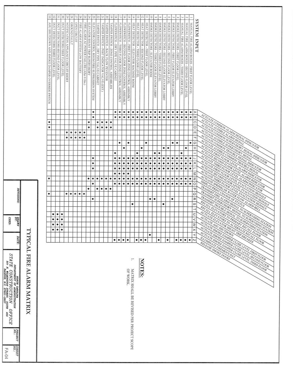
45 - 45 -
SECTION DIGITAL, ADDRESSABLE FIRE-ALARM SYSTEM
 SECTION 283111 - DIGITAL, ADDRESSABLE FIRE-ALARM SYSTEM PART 1 - GENERAL 1.1 RELATED DOCUMENTS A. Drawings and general provisions of the Contract, including General and Supplementary Conditions and Division
FIRE ALARM SYSTEM 1.1 GENERAL REQUIREMENTS
 VALOUR COMMUNITY CENTRE FIRE ALARM SYSTEM Section 28 00 00 GYMNASIUM ADDITION & RENOVATION Page 1 of 3 28 00 00 FIRE ALARM SYSTEM 1.1 GENERAL REQUIREMENTS 1.2 SCOPE 1. The specification covering the General
Mircom FX /01/16
 ENGINEERING SPECIFICATION 954-POINT INTELLIGENT FIRE DETECTION SYSTEM PART 1.0 - GENERAL 1.1. DESCRIPTION: A. This section of the specification includes the furnishing, installation, connection and testing
OSU PROJECT NO PAGE 1 02 NOV 2006 SECTION FIRE ALARM SYSTEM
 OSU PROJECT NO. 30-04-15 PAGE 1 PART 1 GENERAL 1.1 WORK INCLUDED A. Provide all labor, materials, and equipment required to provide a complete and operating system of manual and automatic detection devices,
PWGSC Ontario MULTIPLEX FIRE ALARM SYSTEM Sect Region Project Page 1 Number R
 Region Project Page 1 PART 1 - GENERAL 1.1 REFERENCES.1 CAN/ULC-S524-2006, Standard for the Installation of Fire Alarm Systems..2 CAN/ULC-S525-2007, Audible Signal Device for Fire Alarm Systems..3 CAN/ULC-S526-2007,
SECTION FIRE ALARM STANDARDS REVISED CONSTRUCTION STANDARD
 PART 1 - GENERAL PURPOSE This Standard is intended to assure that fire detection/alarm systems at The University of Texas at Austin provide the highest level of fire safety possible. SCOPE This standard
DIVISION 26 ELECTRICAL SECTION FIRE ALARM SYSTEM
 DIVISION 26 ELECTRICAL SECTION 26 81 11 PART 1 GENERAL 1.01 DESCRIPTION A. Furnish and install all equipment and accessories for a complete local, analog addressable, manually and automatically actuated,
Michigan State University Construction Standards FIRE DETECTION AND ALARM PAGE
 PAGE 283100-1 SECTION 283100 - DIGITAL, ADDRESSABLE FIRE-ALARM SYSTEM PART 1 - GENERAL 1.1 RELATED DOCUMENTS A. Drawings and general provisions of the Contract, including General and Supplementary Conditions
TABLE OF CONTENTS GENERAL... 2 A. DEFINITIONS DIGITAL, ADDRESSABLE FIRE ALARM SYSTEM... 2
 Division 28 ELECTRONIC SAFETY AND SECURITY TABLE OF CONTENTS 28 0000 GENERAL... 2 A. DEFINITIONS...2 28 3111 DIGITAL, ADDRESSABLE FIRE ALARM SYSTEM... 2 A. DESIGN REQUIREMENTS...2 B. CONSTRUCTION REQUIREMENTS...2
1. Floor above/floor below notification. 2. Private alarm notification. 3. Not Used 4. Voice alarm notification. 5. Not Used.
 PART 1 GENERAL 1.01 Scope of Standard A. This Standard is intended to assure that fire alarm and signaling systems at Sam Houston State University provide the highest level of life safety possible. This
Smoke Detector Activation of any smoke detector shall start the alarm verification mode.
 Description: The purpose of the section is to provide the UMCP Design Standards for the design and implementation of Fire Alarm Systems at the UMCP campus. Related Sections: TBD Effective Date: July 10,
COUNTY OF KINGS KINGS COUNTY JAIL EXPANSION PHASE III
 SECTION 28 3111 - DIGITAL ADDRESSABLE FIRE ALARM SYSTEM PART 1 - GENERAL 1.1 RELATED DOCUMENTS A. General provisions of the Contract, including General and Supplementary Conditions and Division 1 Specification
Control Panel. 1.0 GENERAL SCOPE OF WORK Introduction... 2
 Architectural & Engineering Specifications Control Panel 1.0 GENERAL... 2 1.1 SCOPE OF WORK... 2 1.1.1 Introduction... 2 1.2 GENERAL CONDITIONS... 2 1.2.1 After-Sales Support... 2 1.2.2 Quality assurance...
DESIGN & CONSTRUCTION GUIDELINES
 Facilities Management 4202 E. Fowler Avenue, OPM 100 Phone: (813) 974-2625 Design & Construction Tampa, Florida 33620-7550 Website: usf.edu/fm-dc DESIGN & CONSTRUCTION GUIDELINES DIVISION 28 ELECTRONIC
SECTION FIRE ALARM SYSTEMS
 SECTION 16721 FIRE ALARM SYSTEMS PART 1 - GENERAL 1.01 RELATED DOCUMENTS A. The general provisions of the contract including General and Special Conditions and General Requirements shall apply to all work
SECTION FIRE ALARM SYSTEMS
 SECTION 28 3100 PART 1 -GENERAL 1.01 RELATED DOCUMENTS Drawings and general provisions of the Contract, including General and Supplementary Conditions and Division 1 Specification Sections, apply to this
2. HVAC and smoke control systems; fire, smoke, and combination fire/smoke dampers. 5. Central control and monitoring system.
 PART 1 GENERAL 1.01 Scope of Standard A. This Standard is intended to assure that fire detection/alarm systems at The University of Texas at Austin provide the highest level of fire safety possible.. This
Changes in NFPA
 Changes in NFPA 72-2002 2002 Oregon Fire Code Committee November 25, 2003 Michael B. Baker, SET Automatic Fire Alarm Association MikeBaker@afaa.org 2003 Michael B. Baker 1 Table of Contents 1. Administration
Project No Belleville Fire Hall/Headquarters and Emergency Operations Centre Section Belleville, Ontario Page 1 of 10
 Belleville, Ontario Page 1 of 10 1 GENERAL 1.1 GENERAL REQUIREMENTS.1 The General Conditions of CCDC2-2008, and the General requirements of Division 1, form part of this Section and must read in conjunction
PART 1 GENERAL Quality Assurance A. Fire Alarm Contractor Qualifications:
 PART 1 GENERAL 1.01 Quality Assurance A. Fire Alarm Contractor Qualifications: 1 The Fire Alarm contractor shall be an Edwards Systems Technology (EST) designated representative and authorized to sell,
Architect s Project Number of 12 Fire Alarm/Smoke Detection Systems District Master Specs 2013 Edition
 PART 1 GENERAL 1.1 SECTION INCLUDES SECTION 28 31 00 FIRE ALARM AND SMOKE DETECTION SYSTEMS A. Fire alarm and smoke detection systems 1.2 REFERENCES A. NFPA 72 B. NFPA 101 1.3 REGULATORY REQUIREMENTS A.
Update all extract references to NFPA documents (including NFPA 72) in Chapter 3 and related annex material to the latest editions.
 in Chapter 3 and related annex material to the latest editions.") 11/16/12 TerraView First Revision No. 15-NFPA 720-2012 [ Global Input ] Update all extract references to NFPA documents (including NFPA 72) in Chapter 3 and related annex material to the latest editions.
11/16/12 TerraView First Revision No. 15-NFPA 720-2012 [ Global Input ] Update all extract references to NFPA documents (including NFPA 72) in Chapter 3 and related annex material to the latest editions.
SECTION FIRE ALARM
 SECTION 16740 PART 1 - GENERAL 1.1 RELATED DOCUMENTS A. Drawings and general provisions of the Contract, including General and Supplementary Conditions and Division 1 Specification Sections, apply to this
SECTION FIRE ALARM AND SMOKE DETECTION SYSTEMS
 PART 1 GENERAL 1.1 SECTION INCLUDES A. Fire alarm and smoke detection systems 1.2 REFERENCES A. NFPA 72 B. NFPA 101 1.3 REGULATORY REQUIREMENTS A. System: UL listed B. Conform to requirements of NFPA 101
Fire Alarm Acceptance Testing & On-Going Maintenance with The Joint Comm. Standards / Reporting. Prepared Especially for : OSFM TEC 2016
 Fire Alarm Acceptance Testing & On-Going Maintenance with The Joint Comm. Standards / Reporting Prepared Especially for : OSFM TEC 2016 Acceptance Testing 11-2008 Agenda Before you begin Completing the
Rancho Cucamonga Fire Protection District Prevention Bureau Standard
 Rancho Cucamonga Fire Protection District Prevention Bureau Standard Title: Fire Alarm and Monitoring Systems Standard # 9-3 Effective: May 2002 Number of Pages: 7 Updated: December 2016 for consistency
Specification/ Data Sheet
 Specification/ Data Sheet TRITON RP Agent Release Control Panel FEATURES Agent Release Control Panel designed specifically for suppression release operation with: Four initiating device circuits (IDCs)
Addressable Fire Alarm Control Panel
 PRODUCT SPECIFICATION XR2400F Addressable FACP Addressable Fire Alarm Control Panel Description The DMP XR2400F Addressable Fire Alarm Control Panel is an expandable Fire Alarm Control with built-in DACT
DATA SHEET CYBERCAT 254 INTELLIGENT FIRE ALARM CONTROL SYSTEM DESCRIPTION APPROVALS: SYSTEM OPERATION. Form No. D
 DATA SHEET CYBERCAT 254 INTELLIGENT FIRE ALARM CONTROL SYSTEM DESCRIPTION Fike s CyberCat 254 (P/N 10-066) is a state-of-the-art true intelligent digital peer-to-peer modular fire alarm control system.
30.45 Electric Release PDRP-2001
 The PDRP-2001 Fire Alarm Control Panel (FACP) is a six-zone control panel for single and dual hazard deluge and preaction applications. The FACP is compatible with conventional input devices (2-wire or
Lake County / Multi-Department Storage Facility / Project / December 12, 2016 SECTION DIGITAL, ADDRESSABLE FIRE-ALARM SYSTEM
 PART 1 - GENERAL 1.1 RELATED DOCUMENTS SECTION 283111 A. Drawings and general provisions of the Contract, including General and Supplementary Conditions and Division 01 Specification Sections, apply to
Commercial and Light Industrial Fire Alarm Control Panel
 FireSystem 2000 Commercial and Light Industrial Fire Alarm Control Panel Features Easily expandable. All new plug-in board design Two supervised audible circuits Lamp and system trouble circuit test Ground
Data Sheet Fire Safety & Security Products. System Overview. Initiating Circuits SXL-EX FACP 7906
 s Data Sheet Fire Safety & Security Products SXL-EX Fire Alarm Control Panel Conventional Zone Fire Alarm Control Panel ARCHITECT AND ENGINEER SPECIFICATIONS Four (4) zones expandable to eight (8) zones
Conventional Releasing Control Panel
 s Data Sheet Fire Safety Products Conventional Releasing Control Panel Pre-Action Deluge Agent-Releasing Fire System Model TXR-320 Remote configurable Up to two (2) hazard areas Operable with the following:
PART 1 GENERAL Quality Assurance A. Fire Alarm Contractor Qualifications:
 PART 1 GENERAL 1.01 Quality Assurance A. Fire Alarm Contractor Qualifications: 1 The Fire Alarm contractor shall be an Edwards Systems Technology (EST) designated representative and authorized to sell,
Fire Alarm System Fundamentals
 Fire Alarm System Fundamentals Mircom is the largest and oldest privately owned fire alarm and life safety manufacturer in North America and 5th largest overall with 50 years of industry experience. Mircom
WINDOW & HVAC REPLACEMENT PEMBERTON TOWNSHIP BOE REGAN YOUNG ENGLAND BUTERA, PC PROJECT #5450E
 SECTION 283111 DIGITAL ADDRESSABLE FIRE ALARM SYSTEM PART 1 - GENERAL 1.1 RELATED DOCUMENTS: A. Drawings and general provisions of Contract, including General and Supplementary General Conditions of the
SPECIFICATION: AlarmLine TM INTELLIGENT LINEAR HEAT DETECTION
 1. GENERAL SPECIFICATION 1.1 The contractor shall provide an Intelligent AlarmLine Linear Heat Detection System to perform the following functionality: A. Fire Alarm, Supervisory and Trouble-Event Initiation
Moreno Valley Fire Department Fire Prevention Bureau. New and Existing Fire Alarm & Signaling Systems Guideline
 Moreno Valley Fire Department Guideline Approved and Authorized By: Adria Reinertson, Fire Marshal Issued: May 8, 2017 Alarm & Signaling Systems PURPOSE Fire alarm and signaling systems are designed to
PEGAsys. Multi-Loop Intelligent Suppression Control System FEATURES DESCRIPTION. Effective: March 2007 K
 PEGAsys Multi-Loop Intelligent Suppression Control System A UTC Fire & Security Company Effective: March 2007 K-76-028 FEATURES UL Listed CSFM Approved MEA Approved Peer-to-Peer Networking (to 32 nodes)
LifeAlarm Fire Alarm Control Panels
 LifeAlarm Fire Alarm Control Panels UL, ULC Approved* Features Control panel operator convenience features: Wide viewing angle 2 x 20 (40 character) alphanumeric LCD and dedicated LEDs provide convenient
DATA SHEET CHEETAH XI 50 INTELLIGENT SUPPRESSION CONTROL SYSTEM DESCRIPTION APPROVALS: SYSTEM OPERATION. Form No. D
 DATA SHEET CHEETAH XI 50 INTELLIGENT SUPPRESSION CONTROL SYSTEM DESCRIPTION Fike s Cheetah Xi 50 (P/N 10-071) is a state-of-the-art true intelligent digital peer-to-peer modular suppression control system.
TECHNICAL DATA. Humidity: 85% Relative Humidity (non-condensing) at 90 F (32 C) maximum.
 at 90 F (32 C) maximum.") September 29, 1997 Firecycle III 433 a 1. PRODUCT NAME VIKING Model E-1 Manufactured 1997 Present 2. MANUFACTURED FOR THE VIKING CORPORATION 210 N Industrial Park Road Hastings, Michigan 49058, U.S.A.
September 29, 1997 Firecycle III 433 a 1. PRODUCT NAME VIKING Model E-1 Manufactured 1997 Present 2. MANUFACTURED FOR THE VIKING CORPORATION 210 N Industrial Park Road Hastings, Michigan 49058, U.S.A.
CHEETAH XI INTELLIGENT SUPPRESSION CONTROL SYSTEM
 CHEETAH XI INTELLIGENT SUPPRESSION CONTROL SYSTEM DESCRIPTION Fike s Cheetah Xi (P/N 10-068) is a state-of-the-art true intelligent digital peer-topeer modular suppression control system. It is ideal for
SECTION FIRE ALARM SYSTEM PART 1 GENERAL
 SECTION 16720 - FIRE ALARM SYSTEM PART 1 GENERAL 1.1 SCOPE & RELATED DOCUMENTS A. The work covered by this section of the specifications includes the furnishing of all labor, equipment, materials, and
FIRE DETECTION SYSTEM SPECIFICATION FOR MODEL XR200
 FIRE DETECTION SYSTEM SPECIFICATION FOR MODEL XR200 1.0 General 1.1 Manufacturer Manufacturer of the Fire Alarm Control Panel (FACP) equipment shall be: Digital Monitoring Products, Incorporated 2500 N.
SECTION DIGITAL, ADDRESSABLE FIRE-ALARM SYSTEM
 SECTION 13852- PART 1- GENERAL 1.1 RELATED DOCUMENTS A. Drawings and general provisions of the Contract, including General and Supplementary Conditions and Division 1 Specification Sections, apply to this
TECHNICAL DATA OBSOLETE
 Deluge Devices 270a 1. PRODUCT NAME VIKING PAR-3 Available since 1991 2. MANUFACTURED FOR: THE VIKING CORPORATION 210 N. Industrial Park Road Hastings, Michigan 49058 U.S.A. Telephone: (269) 945-9501 (877)
The CWSI System CALL WITH QUESTIONS. RELY ON OUR KNOWLEDGE. DEPEND ON OUR EXPERIENCE. (800)
") The CWSI System The CWSI wireless fire alarm product line offers system versatility like none other. Frequency Hopping Spread Spectrum Technology (FHSS), coupled with Bi-directional RF Communication, Repeater
The CWSI System The CWSI wireless fire alarm product line offers system versatility like none other. Frequency Hopping Spread Spectrum Technology (FHSS), coupled with Bi-directional RF Communication, Repeater
Soft Start Series MP700 Solid State, Reduced Voltage
 Metron Fire Pump Controls and Accessories Soft Start Series MP700 Solid State, Reduced Voltage Metron Fire Pump Controllers conform to the latest requirements of National Fire Protection Association s
Bold items are particular to the City of Euless
 EULESS FIRE DEPARTMENT FIRE MARSHAL S OFFICE INFORMATION LINE: Revised 8/2004 Fire Chief Lee Koontz Fire Marshal Paul Smith EFD-FMO 3-1 2003 International Fire & Building Code as Amended NFPA Standards
16.34 Multiplex Fire Alarm System Construction Standards Page 1 of 5
 Construction Standards Page 1 of 5.1 General Description.1 The University requires that all new fire alarm system control panel, components, and devices, as required for the project, be Secutron 2900 Series
Across-the-Line SERIES MP300 Combined Manual and Automatic
 Across-the-Line SERIES MP300 Combined Manual and Automatic Metron Fire Pump Controllers conform to the latest requirements of National Fire Protection Association s Standard for Centrifugal Fire Pumps
A. This Section covers fire alarm systems, including initiating devices, notification appliances, controls, and supervisory devices.
 SECTION 28 31 11 ADDRESSABLE FIRE ALARM SYSTEM 1. GENERAL 1.1 SUMMARY A. This Section covers fire alarm systems, including initiating devices, notification appliances, controls, and supervisory devices.
MODUL-R FIRE ALARM CONTROL PANELS. MR-2900/MR-2920 Addressable Fire Alarm Control Panels MEA. Features. Description
 MODUL-R FIRE ALARM CONTROL PANELS MR-2900/MR-2920 Addressable Fire Alarm Control Panels Description MR-2900 Fire Alarm Control Panel The MR-2900 fire alarm system control unit is the heart of a sophisticated
Hinesville First United Methodist Church SECTION DIGITAL, ADDRESSABLE FIRE-ALARM SYSTEM
 SECTION 28 3111 DIGITAL, ADDRESSABLE FIRE-ALARM SYSTEM PART 1 - GENERAL 1.01 SUMMARY A. Section Includes: 1. Fire-alarm control unit. 2. Manual fire-alarm boxes. 3. System smoke detectors. 4. Heat detectors.
The following information shall become and form part of the contract documents.
 October 4, 206 To: Attention: Re: All Bidders All Bidders JCBE Gymnasium HVAC Upgrades BC#: 206433 Edmonds Project No.: BHM6090 All bidders, The following information shall become and form part of the
SECTION FIRE ALARM, DETECTION AND NOTIFICATION SYSTEM
 SECTION 16732 FIRE ALARM, DETECTION AND NOTIFICATION SYSTEM PART 1 GENERAL 1.01 SUMMARY A. The work covered by this Section of the Specification shall include all labor, equipment, materials and services
Fire alarm system specification for multiple tenant retail buildings
 Date: June 20, 2011 Project name: Baederwood Shopping Center Multiple Tenant Buildings B & C City/ State: Abington, PA Landlord s Vendor Contact: Dan Morrin Jr., NECCO Security Phone: (215)638-7999 Email:
DENVER PUBLIC SCHOOLS DESIGN AND CONSTRUCTION STANDARDS This Standard is for guidance only. SECTION FIRE ALARM SYSTEM (POINT GRAPHIC SYSTEM)
") PART 0 DESIGN STANDARDS 0.01 USE OF THIS STANDARD A. Due to the extent of detail provided in this standard, the A/E may choose to edit this standard and incorporate portions of this standard in the construction
PART 0 DESIGN STANDARDS 0.01 USE OF THIS STANDARD A. Due to the extent of detail provided in this standard, the A/E may choose to edit this standard and incorporate portions of this standard in the construction
C. All control equipment must have transient protection devices to comply with UL864 requirements.
 SECTION 28 31 11 - PART 1 - GENERAL 1.1 SCOPE & RELATED DOCUMENTS A. The work covered by this section of the specifications includes the furnishing of all labor, equipment, materials, and performance of
Standard of Practice - Fire Alarm Systems. NOTE: Significant revisions or additions to the previous standards are highlighted in italics.
 A28.1 Standard of Practice - Fire Alarm Systems NOTE: Significant revisions or additions to the previous standards are highlighted in italics. OBJECTIVE OF STANDARD To provide compliant smart addressable
Concerns: Affects: Dated: June 12, SECTION 1: GENERAL Scope Work Included... 3
 Technical Service Note Detection Systems, Inc. Fairport, New York 14450-9199 Technical Service (800) 374-7454 Sales: (800) 289-0096 and (585) 223-4060 Fax: (585) 223-9180 Concerns: Affects: Dated: June
Control/Communicator
 Architectural & Engineering Specifications Control/Communicator 1.0 GENERAL... 2 1.1 SCOPE OF WORK... 2 1.1.1 Introduction... 2 1.2 GENERAL CONDITIONS... 2 1.2.1 After-Sales Support... 2 1.2.2 Quality
SECTION AUTOMATIC TRANSFER SWITCHES
 SECTION 26 36 23 AUTOMATIC TRANSFER SWITCHES PART 1 - GENERAL 1.1 RELATED DOCUMENTS A. General provisions of the Contract, including General and Supplementary Conditions and Division 01 Specification Sections,
Intelligent addressable fire alarm control panel
 Intelligent addressable fire alarm control panel Input current consumption: Panel rating: Batteries: Networking and Interfaces Panel to panel communication: Number of panels: Interface port: System capacity
UNIVERSITY SERVICES ANNEX James Madison University Harrisonburg, Virginia State Project Code: Architect s Project Number:
 SECTION 283112 DIGITAL ADDRESSABLE FIRE ALARM SYSTEM VOICE NOTIFICATION PART 1 GENERAL 1.1 SUMMARY NETWORK FIRE ALARM CONTROL PANEL (NODE) A. Network fire alarm control panels shall include all features
16721 FIRE ALARM AND DETECTION SYSTEMS
 16721 FIRE ALARM AND DETECTION SYSTEMS PART 1: GENERAL 1.01 QUALITY ASSURANCE A. The integrated fire alarm system including all equipment, components, and accessories shall be UL listed for the purpose
Functional Performance Test
 Fire Alarm Control Panel & Fire Alarm Annunciator Panel Notify all building occupants that testing will be conducted. Fire alarm contractor shall have personnel with 2-way radios at the fire alarm control
Changes to this Division since the last issuance are indicated with yellow highlighted text.
 Table of Contents 28 10 00 ELECTRONIC ACCESS CONTROL AND INTRUSION DETECTION... 2 A. GENERAL... 2 B. DESIGN REQUIREMENTS... 2 C. CONSTRUCTION REQUIREMENTS... 3 28 20 00 ELECTRONIC SURVEILLANCE... 4 A.
UltraLITE Model ELU Centralized Emergency Lighting Inverter 4.2 KW- 5 KW
 12/23/16 Rev 9 UltraLITE Model ELU General Specification 4.2 KW to 5 KW UltraLITE Model ELU Centralized Emergency Lighting Inverter 4.2 KW- 5 KW 1.0 General General Specification This specification describes
Laptop / PC Programming Manual
 Laptop / PC Programming Manual Doc. # Fire PC Program rev B 01.07 This Document is property of Evax Systems, Inc. The Evax Fire Solutions Programmer Components 2 1.0 System Setup 4 1.1 Interface Setup
AL802ULADA. NAC Power Extender. Installation Guide. (See Application Guide for additional information) Rev
 Rev") AL802ULADA NAC Power Extender Installation Guide (See Application Guide for additional information) Rev. 031703 Overview: The Altronix AL802ULADA is an extremely cost effective 8 amp voltage regulated
AL802ULADA NAC Power Extender Installation Guide (See Application Guide for additional information) Rev. 031703 Overview: The Altronix AL802ULADA is an extremely cost effective 8 amp voltage regulated
Full Service Central Station Fire Alarm Listing Evaluation
 Full Service Central Station Fire Alarm Listing Evaluation Listing Evaluation A UL Listing project includes: 1. Evaluating the central station facility for compliance with UL 827, Central-Station Alarm
SECTION FIRE DETECTION AND ALARM
 PART 1 - GENERAL 1.1 RELATED SECTIONS: Refer to Section 15300 for requirements regarding fire protection systems. 1.2 SCOPE OF SECTION: This section contains the requirements for equipment and installation
NFPA 72 Code Changes vs 2013
 NFPA 72 Code Changes - 2010 vs 2013 AFAA-NE Westborough, MA February 7, 2018 Richard Roux NFPA 72 National Fire Alarm and Signaling Code Overview and 2013 Changes NFPA 72 1993 Edition Aug 20, 1993 1996
1.3 REFERENCE STANDARDS
 SECTION 28 4600 FIRE DETECTION AND ALARM PART 1 -GENERAL 1.1 SECTION INCLUDES A. Fire alarm system design and installation, including all components, wiring, and conduit. B. Circuits from protected premises
SECTION ADDRESSABLE FIRE ALARM SYSTEM
 SECTION 16723 ADDRESSABLE FIRE ALARM SYSTEM 1 PART 1 GENERAL 1.1 DESCRIPTION A. This section outlines the requirements for the installation, programming and configuration of Addressable Fire Alarm System
OKLAHOMA STATE UNIVERSITY
 ENVIRONMENTAL HEALTH & SAFETY ADDRESSABLE FIRE ALARM SYSTEM STANDARD Revised 6/15 Revised: 6/15 Contact(s) Implementation Date Comments Gerald Petre, EHS June 2016 Review and Update Page 1 1.1 GENERAL
Voice Annunicated Fire Alarm System Page 1 of 26
 Last Update: May 12, 2017 Consultant s Handbook Page 1 of 26 A. General: 1. Voice annunciated, intelligent, addressable fire alarm systems at BSU are used in all residence halls, high rise buildings and
The supplier and installer of the system should be approved by the local civil defence authority.
 ANALOGUE ADDRESSABLE FIRE ALARM SYSTEM 1. Scope of Work The contractor shall supply, install, test and commission a modern Analogue Addressable Fire Detection and Alarm System of an approved manufacturer
CONVENTIONAL FIRE ALARM CONTROL UNITS. MR-2300 SERIES Fire Alarm Control Units MEA
 CONVENTIONAL FIRE ALARM CONTROL UNITS MR-2300 SERIES Fire Alarm Control Units Description Secutron s MR-2300 Series fire alarm control panels consist of six and twelve zone models which are equipped with
SECTION NURSE CALL SYSTEM
 NURSE CALL SMARTCARE NURSE CALL SOLUTION Architectural Specifications Part 1 General SECTION 275223 - NURSE CALL SYSTEM 1.0 Summary 1.1 This section includes nurse call system and requirements for system
FIRE & LIFE SAFTEY STANDARD
 Title: Effective Date: 01/01/14 Revised Date: 1/1/14 Code References: Title 16, Chapter 16.16 of the Roseville Municipal Code, NFPA 72 Note: This standard is a summary of Fire Department clarifications
PART IV DETAILED SPECIFICATION
 PART IV DETAILED SPECIFICATION PART IV DETAILED SPECIFICATIONS SECTION ONE: GENERAL 1.1 Scope A. This specification document provides the requirements for the installation, programming and configuration
CARD ACCESS CONTROL SYSTEM
 SECTION 13851 CARD ACCESS CONTROL SYSTEM PART 1 GENERAL 1.01 SUMMARY A. Section Includes: A complete, operable, tested, integrated proximity access control system, to operate on a proximity principle where
16721 FIRE ALARM AND DETECTION SYSTEMS
 16721 FIRE ALARM AND DETECTION SYSTEMS PART 1: GENERAL 1.01 QUALITY ASSURANCE A. The integrated fire alarm system including all equipment, components, and accessories shall be UL listed for the purpose
Pakenham Branch Library Section MacFarlane Street MULTIPLEX FIRE ALARM SYSTEM Project No Page 1 of 12
 Project No. 16563.001 Page 1 of 12 1. General 1.1. WORK INCLUDED 1.1.1. Section 26 05 01 GENERAL INSTRUCTIONS FOR ELECTRICAL SECTIONS. 1.1.2. Section 26 05 04 SUBMITTALS/SHOP DRAWINGS. 1.1.3. Section 26
FireSystem 2000 Commercial and Light Industrial Fire Alarm Control Panel
 PROTECTOWIRE FireSystems Features Easily expandable Two supervised audible circuits Lamp and system trouble circuit test Ground fault detection Initiating device circuit (IDC) alarm test Monitors up to
Model 17A00 Expansion Enclosure
 HOME AUTOMATION, INC. Model 17A00 Expansion Enclosure Installation Manual Document Number 17I00-1 Rev A March, 2002 Home Automation, Inc. Model 17A00 Expansion Enclosure Installation Manual Document Number
MR-2602 Two Zone Fire Alarm Control Panel
 MR-2602 Two Zone Fire Alarm Control Panel Installation Manual Secutron LT-2015 Rev.3 July 2010 Table of Contents 1 Introduction 1.1 The MR-2602 Fire Alarm Control Unit... 11 1.1.1 General features...
Consultant Specification AGILE Wireless Fire Detection System
 Contents Scope of Work... 2 The EN54 Part 2 & 4 Fire System... 2 Standards... 2 Wireless Intelligent Photoelectric Smoke Detector Specification... 4 Wireless Intelligent Thermal Heat Detector Specification...
D8024, D9024, D10024 Analog Fire Alarm Control Panels Programming Guide
 System Reset Trou ble Silence Ala rm Silence Manual Ala rm ENTER NO YES Letters Numb ers Keyword Radionics System Reset Trouble Silence Alarm Silence Manual Alarm ENTER NO YES Le ters Numbers Keyw ord
SECTION FIRE DETECTION AND ALARM
 PART 1 - GENERAL 1.1 DESCRIPTION SECTION 28 46 00 SPEC WRITER NOTES: 1. The A/E must obtain a copy of the VA ENGINEERING GUIDE FOR FIRE PROTECTION DESIGN which provides fire alarm system criteria that
TrueAlarm Fire Alarm Systems
 OPERATOR OPERATOR OR TROUBLE CONDITION: TO : FIRE PRIORITY 2SYSTEM SYSTEM SIGNALS POWER INDICATOR. SUPERVISORYTROUBLE SILENCED ON D. TO SILENCE SIGNALS: - PRESS " SILENCE". SUPV TBL SYSTEM ACK ACK ACK
MPC-6000 / MPC-7000 / RND-2
 MPC-6000 / MPC-7000 / RND-2 Fire Alarm System Control Unit Installation, Operation and Maintenance Manual Siemens Building Technologies, Inc. 8 Fernwood Road Florham Park, NJ 07932 Tel: (973) 593-2600
ALK-V PHOTOELECTRIC SMOKE SENSOR
 ALK-V PHOTOELECTRIC SMOKE SENSOR APPLICATION The HOCHIKI America ALK-V Photoelectric Smoke Sensor is particularly suited to detecting optically dense smoke typical of fires involving materials such as
SECTION DIGITAL, ADDRESSABLE FIRE ALARM SYSTEM
 SECTION 283111 DIGITAL, ADDRESSABLE FIRE ALARM PART 1 - GENERAL 1.1 GENERAL A. This Section includes the following: 1. Fire-alarm control panel. 2. Manual fire-alarm boxes. 3. Smoke detectors. 4. Heat
MOBILE FIRE - RESCUE DEPARTMENT FIRE CODE ADMINISTRATION
 MOBILE FIRE - RESCUE DEPARTMENT FIRE CODE ADMINISTRATION Fire Alarm System Plan Review 2009 International Fire Code and 2010 NFPA 72 Date of Review // BLD201 - Project Address: Project Name: _ Professional
Automatic Fire Alarm Association Webinar On Inspection, Testing, And Maintenance Of Fire Alarm Systems
 Automatic Fire Alarm Association Webinar On Inspection, Testing, And Maintenance Of Fire Alarm Systems Your Presenter: Merton Bunker, PE Inspections and tests are intended to reduce or limit: Loss of life