MODEL A-316 CARBON MONOXIDE (CO) MONITOR AND ALARM FOR COMPRESSED AIR TESTING
|
|
|
- Augustus Watts
- 5 years ago
- Views:
Transcription
1 MODEL A-316 CARBON MONOXIDE (CO) MONITOR AND ALARM FOR COMPRESSED AIR TESTING FOR OPERATION FROM 115 AC POWER Andersen Medical Gas 12 Place Lafitte Madisonville, LA
2
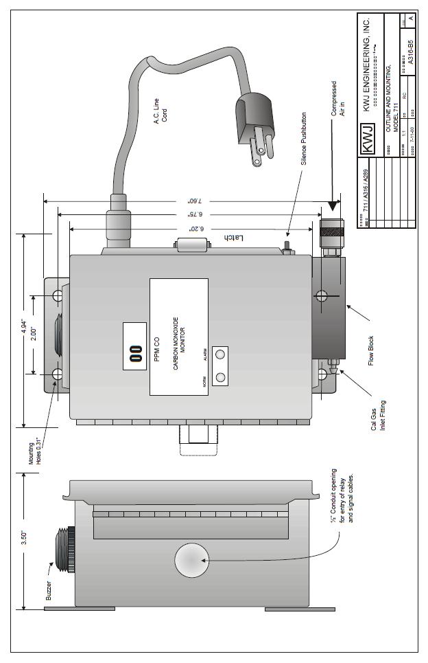
3 A I. INTRODUCTION This Model A316 Carbon Monoxide (CO) Monitor and Alarm is a 115 V AC dust-resistant instrument that can be surface-mounted as close as possible to the air supply but outside any classified hazardous area. It continuously monitors a compressed air sample connected to its sample inlet and it gives an alarm when: -the CO in the sample exceeds a preset level (adjustable, initially set at 10 PPM). -there is a discontinuity in the detector circuit It indicates CO concentration on a digital display, and has a pilot light to verify that the instrument is on and operating properly. The instrument is assembled into a powder-coated sheet metal housing 4" x 6" x 3½ overall. A 1/8 FPT opening for introducing the sample gas is located in the right hand side of the flow block at the bottom of housing. Visible through windows in the front face are the LCD display showing ppm CO, plus pilot and alarm lights. The 3-wire power cord plugs into a RFfiltered socket on the upper right side, and the alarm buzzer extends through the top. II. DETAILED DESCRIPTION When the hinged and gasketed front door is opened after releasing the latch on the right hand side, the interior is visible and accessible. Each major component is described in this section. A. Main Circuit Board The electronic circuit board occupies the main part of the housing, toward the front. It is secured by two slotted bars, and it can be removed if necessary by taking out two screws holding the lower bar. Electrical connections are by cables which connect to sockets on the rear. On the front face are these components of interest to the user: 1. Display is a liquid crystal type which reads from 0 to 199 PPM of CO in steps of one digit. 2. ZERO potentiometer, the lower of the group of three multi-turn potentiometers directly to the right of the display. It is used to set reading to 00 while known CO-free air is passing through the system. 3. SPAN potentiometer, directly above the ZERO potentiometer, is used to set the reading to a correct value while a known calibrating
4 A sample is passing through the system. 4. ALARM potentiometer, directly to right of SPAN potentiometer, is used to set the level at which the alarm is activated. Generally this is initially set at 10 PPM ma potentiometer, directly below the SPAN potentiometer, is used to set the 100 ppm signal output to 20.0 ma. This is a factory adjustment and is intentionally not marked ma potentiometer, directly below the 20 ma potentiometer, is used to set the zero signal output to 4.0 ma. This is also a factory adjustment. 7. NORMAL light, green, shows that power is being provided to the circuit and that the system is in normal operation. 8. ALARM light, red, comes on and glows steadily when CO is detected above the alarm point level. It also indicates a sensor failure or disconnection by blinking on and off. In normal operation, a slight flicker can be seen in the red light, a little faster than once per second, as a confirmation of normal operation. B. Power Supply The instrument internally operates from 12 V DC. This is supplied by a modular 115 AC to 12 V DC power supply. The built-in power supply is supported on a rectangular printed circuit board mounted to standoffs at the rear of housing. When the AC power cord is plugged in, AC power flows to the AC end of the power supply, and 12 volts DC flows from the DC end of the power supply to the main board. AC power enters the housing through an EMI filter socket in the upper right hand corner of case. The AC power cord has a standard grounding-type plug for a normal 115 AC power outlet and the instrument end mates with the filter socket. C. Flow System The air to be analyzed passes through the instrument under its own pressure. The components it flows through, in sequence are: 1. Sample inlet, 1/8 FPT size, to accommodate any suitable tubing fitting having a 1/8 male pipe connection. 2. Flow block, a bored aluminum block with a cavity for receiving and sealing the CO sensor, is secured to the outer bottom of the case. A porous metal flow restrictor reduces the pressure of the compressed air to atmospheric pressure before it reaches the sensor. The CO sensor seals to the block by means of an O-ring seal against the bottom of the cavity.
5 A CO sensor, a three-electrode electrochemical device in a cylindrical plastic housing, responds to any CO that is present in the atmosphere passing over the lower face. CO diffuses through a permeable membrane and enters into an electrochemical reaction, producing a current directly and linearly proportional to the CO content. Sensor plugs into four sockets on the face of a small circuit board which connects by three wires to the main circuit board. This small circuit board is held down by two screws which provide pressure against the O-ring seal to prevent leakage around the sensor. D. External Connections Two terminal blocks are installed on the lower crossbar. The one on the left has three screw terminals, for connection to the internal alarm relay, and the one on the right has two screw terminals for a 4-20 ma signal circuit. Wires to each of these two external circuits can enter the housing through the ½" conduit opening in the left hand side of the case. Connections are as follows. 1. The internal relay has 10 amp SPDT contacts, which are brought to the marked terminals C, NO and NC. Notes for connection of internal relay: The internal relay is normally energized to enable a fail-safe external connection in accordance with NFPA 99C, Item , as an indication of loss of power. A separately powered external alarm or other signal device should be wired through the relay terminals C and NC, and will be activated whenever the instrument is not receiving power. The same external alarm action will occur when the CO reading rises to the alarm level and the internal alarm circuit is activated. Terminals C and NO will be connected in normal operation, with power on and CO reading between 0 and the alarm point (usually 10 ppm). Note: Whenever the system is intentionally turned off, some extra steps will be required to disable the external alarm, which otherwise will respond to the loss of power. 2. The 4-20 ma signal circuit is brought to the two terminals marked + and -. Output signal is 4.0 ma at 0 ppm, 20.0 ma at 100 ppm. E. External Components 1. Buzzer, a solid-state sounding device on the top of the case. 2. Flow block, described above, is secured to the outside bottom of the case, and an opening in the case allows the sensor to be
6 A inserted from inside the case. 3. Calibration gas inlet fitting, on left-hand end of flow block, is a hose barb with internal orifice that restricts flow of calibration gas as it enters the block during calibration. A second opening on the rear of the block provides for exhaust of the calibration gas to prevent pressure buildup during calibration. 4. Alarm Silence switch, a pushbutton on the right hand side, when pressed activates a time delay circuit that holds the buzzer silent for 4 minutes, then re-energizes it if the reading remains above the alarm level. III. OPERATION A. Placing in operation Note: This procedure presumes the availability of a calibration kit similar to the # K. If one is not already available it should be purchased at the time the system is activated. 1. Install the instrument in the desired location, close to the air supply and to a source of power, and where it will be reasonably protected but readily seen. Mount the housing by means of #10 screws through the flanges top and bottom. 2. Make external relay and/or 4-20 signal connections as desired, referring to II.E. above. 3. Connect the air supply to be monitored, to the 1/8 FPT opening in the outer face of flow block, using appropriate tubing and fittings. CAUTION: This Carbon Monoxide Monitor must be connected to a suitable filter unit providing clean air, free of oil, water, and dust. 4. Using the flowmeter and tube supplied with the calibration kit, attach the inlet end of tube to the calibration fitting on left side of flow block. Turn on air pressure. 5. While holding a finger over the small hole in rear of flow block, observe reading on flowmeter. It should read at least 0.3 while held in vertical position. This confirms that sample flow system is working. 6. Connect power cord to the nearest AC power source. 7. When connected, the green light should come on and the red light and buzzer may also come on momentarily. The green light should flash for about 15 seconds. Display should then show a reading of 00 or close to it. 8. Open case by pulling forward on latch. Turn ZERO potentiometer clockwise to bring display to the desired alarm setting, for example 10 ppm. If the alarm does not come on, or comes on too soon, adjust it
7 A using the ALARM ADJ potentiometer. Clockwise rotation decreases the alarm level. Then set reading back to Connect a source of nitrogen or CO-free air to calibration gas inlet, using the flowmeter supplied with calibration kit, and set flow to If reading is other than 00, then turn the ZERO potentiometer to obtain a zero reading; clockwise rotation increases reading. 11. Disconnect the air sample from calibration inlet, connect a known sample of 10 ppm of CO in air or nitrogen, and again set the flow to 1.0. Note: The alarm buzzer can be silenced by pressing the silence button on lower right hand side. This will lock the audible alarm out for 4 minutes. 12. Verify that the display reading increases and the alarm light and buzzer operate. 13. If reading does not reach the desired level corresponding to the known gas concentration, adjust it using the SPAN potentiometer. Clockwise rotation will increase reading. 14. Remove the CO sample and be sure the air line sample is connected to the sample inlet. 15. Instrument is now in operation, and will actuate an alarm if CO concentration rises above the preset alarm level. Note: The above steps are needed only for the first operation and periodically during the life of the instrument. B. Normal Operation 1. Instrument will analyze the sample and show CO content on the display, in parts per million (PPM). The green NORMAL light will glow continuously and the red ALARM light will flicker about once a second. 2. When the CO concentration exceeds the alarm point (initially set at 10 PPM) the red ALARM light will come on steady, the green NORMAL light will go out and the buzzer will sound a steady tone. The internal alarm relay will activate, and any connected external circuits will respond accordingly. 3. When the CO concentration drops below the alarm setting, the indicators will automatically return to normal. C. Abnormal Indications Detector open circuit: If there is a discontinuity in one of the detector leads, the indicator lights will show as follows:
8 A Working Electrode (WE) line (red wire) - - red and green light blink on and off, accompanied by buzzer. Display goes to SC. 2. Counter Electrode (CE) line (black wire) - - red and green light blink on and off, accompanied by buzzer. Display goes to SC. 3. Reference Electrode (RE) line (blue wire) - - CO reading goes off scale positive (1----), red lamp comes on steady, green lamp off and buzzer sounds continuously. 4. Entire detector disconnected, - - same as 1. or 2. above. IV. MAINTENANCE A. Routine Maintenance 1. Each day or period of operation, verify reading close to 00. Adjust if needed. 2. Every 3 months, check calibration. 3. Replace sensor whenever reading cannot be set high enough, during calibration B. Sensor Replacement 1. Unplug or disconnect power cable. 2. Open instrument cover. 3. Loosen and remove the two screws extending up from the bottom of flow block, into the threaded nuts of the sensor circuit board. This will allow the sensor with board to be lifted up and out of the block. Unplug sensor from board. 4. Install new sensor in the same position, after making sure the O-ring is in place at the bottom of the cavity. Insert and tighten the screws, which will pull the sensor down into contact with the O-ring seal. 5. Reconnect power and allow new sensor to stabilize. 6. After two hours of operation, recheck zero and span adjustments as explained in III. A. 7. Discard old detector cell, keeping in mind that it contains a small amount of sulfuric acid. C. Main Circuit Board The principal electronic components are all installed on the main printed circuit board, which is retained within the housing by two slotted bars. To remove the board, take out the two screws holding the lower bar, after which the board can be pulled out and the wires unplugged at their connectors.
9 A Keep track of the proper position of each connector. D. Buzzer Once the circuit board is removed, the buzzer can easily be taken out by unscrewing the locking ring at the top of case. E. Power Supply Once the circuit board is removed, this gives access to the power supply on its small subpanel board. First take out the EMI filter block by removing two screws, unplugging the white and black wires, and disconnecting the green wire at the screw post. Then take out the two screws holding the board to the case, pull out the board and power supply assembly. F. Flow Restrictor If sample flow rate as tested under III. A.4 declines below 0.25, the flow restrictor may have become partially plugged. Replacement is not a field operation, and the instrument should be returned to the factory for correction. V. CALIBRATION KIT A field calibration kit is offered for use in accurate adjustment of the instrument. It consists of one compressed gas cylinder containing 100 ppm CO in air, and one containing 100% nitrogen, all in a carrying case complete with flow adjustment valve, tubing, a flowmeter and a small screwdriver. To adjust the reading accurately: 1. Shut off compressed air supply, while instrument is in operation. 2. Connect the tubing to the flow adjustment valve and to the flowmeter. Connect the flowmeter outlet tube to the flow block hose barb. 3. Install flow adjustment valve on nitrogen cylinder. This will produce a flow which can be set to 0.6 scfh using the valve. 4. Watch display, and after reading stabilizes set reading to 00 using ZERO potentiometer. 5. After adjustment, connect 100 ppm CO cylinder in the same way. 6. Set flow to 0.6 and adjust SPAN to give reading corresponding to the value marked on the cylinder, about 100 ppm. 7. Restore all connections to original state. 8. Accuracy of instrument when calibrated as above, after careful zero adjustment, is within ± 1 ppm over the range 0-15 ppm, within ± 2
10 A ppm from VI. PARTS LIST The following is a list of items that may need replacement during the life of the instrument. Part No. DESCRIPTION Tubing, ¼ O-ring K Cal gas inlet K Flow block complete with flow restrictor K Sensor cable with circuit board Buzzer, replacement 57-A316 Circuit board, main A Cell, CO detector K Calibration Kit, consisting of: K Cylinder 100 ppm CO K Cylinder 100% N K Valve K Tube with flowmeter K Carrying case K Screwdriver
11 A
MODEL 5800A CARBON MONOXIDE (CO) MONITOR AND ALARM SAMPLE-DRAWING TYPE
 MONITOR AND ALARM SAMPLE-DRAWING TYPE") MODEL 5800A CARBON MONOXIDE (CO) MONITOR AND ALARM SAMPLE-DRAWING TYPE 11//07 A153-021500-1 INSTRUCTION MANUAL - MODEL 5800A CO ALARM I INTRODUCTION This MST Model 5800A Carbon Monoxide (CO) Alarm is a
MODEL 5800A CARBON MONOXIDE (CO) MONITOR AND ALARM SAMPLE-DRAWING TYPE 11//07 A153-021500-1 INSTRUCTION MANUAL - MODEL 5800A CO ALARM I INTRODUCTION This MST Model 5800A Carbon Monoxide (CO) Alarm is a
MST, INC. MODEL 2002 CARBON MONOXIDE MONITOR (AMBIENT-TYPE) OWNER S MANUAL
 OWNER S MANUAL") MST, INC. MODEL 2002 CARBON MONOXIDE MONITOR (AMBIENT-TYPE) OWNER S MANUAL IMPORTANT WARNING WHEN THE CO MONITOR IS CORRECTLY INSTALLED AND MAINTAINED, IT MONITORS THE LEVEL OF CARBON MONOXIDE IN ITS SURROUNDINGS..
MST, INC. MODEL 2002 CARBON MONOXIDE MONITOR (AMBIENT-TYPE) OWNER S MANUAL IMPORTANT WARNING WHEN THE CO MONITOR IS CORRECTLY INSTALLED AND MAINTAINED, IT MONITORS THE LEVEL OF CARBON MONOXIDE IN ITS SURROUNDINGS..
Carbon Monoxide Monitor and Retrofit Carbon Monoxide Monitor Kit W-2808/37027
 Carbon Monoxide Monitor and Retrofit Carbon Monoxide Monitor Kit W-2808/37027 User Instructions (Keep these instructions for reference) 3M W-2808 Supplied Air Respirator SAR Retrofit CO Monitor Kit 1 TABLE
MST, INC. MODEL 2002 CARBON MONOXIDE MONITOR OWNER S MANUAL
 MST, INC. MODEL 2002 CARBON MONOXIDE MONITOR OWNER S MANUAL IMPORTANT WARNING WHEN THE CO MONITOR IS CORRECTLY INSTALLED AND MAINTAINED, IT MONITORS THE LEVEL OF CARBON MONOXIDE IN THE RESPIRATORY AIR
RK-OXY Oxygen Sample-Draw Detector Operator s Manual Part Number: RK Revision: P1 Released: 7/18/02
 35-3000RK-OXY Oxygen Sample-Draw Detector Operator s Manual Part Number: 71-0071RK Revision: P1 Released: 7/18/02 RKI Instruments Inc. 1855 Whipple Road Hayward, CA 94544 PH: 800-754-5165 Fax: 510-441-5650
MST, INC. MODEL 2002 OXYGEN MONITOR (AMBIENT-TYPE) OWNER S MANUAL
 OWNER S MANUAL") MST, INC. MODEL 2002 OXYGEN MONITOR (AMBIENT-TYPE) OWNER S MANUAL IMPORTANT WARNING WHEN THE OXYGEN MONITOR IS CORRECTLY INSTALLED AND MAINTAINED, IT MONITORS THE LEVEL OF OXYGEN IN ITS SURROUNDINGS 07/11
MST, INC. MODEL 2002 OXYGEN MONITOR (AMBIENT-TYPE) OWNER S MANUAL IMPORTANT WARNING WHEN THE OXYGEN MONITOR IS CORRECTLY INSTALLED AND MAINTAINED, IT MONITORS THE LEVEL OF OXYGEN IN ITS SURROUNDINGS 07/11
Carbon Monoxide Sample-Draw Detector Operator s Manual
 35-3001-04-01 Carbon Monoxide Sample-Draw Detector Operator s Manual Part Number: 71-0395 Revision: 0 Released: 8/4/17 www.rkiinstruments.com WARNING Read and understand this instruction manual before
Combustible Gas Sample-Draw Detector Operator s Manual
 35-3001-01 Combustible Gas Sample-Draw Detector Operator s Manual Part Number: 71-0282RK Revision: A Released: 8/3/17 www.rkiinstruments.com WARNING Read and understand this instruction manual before operating
RKA-LEL Sample Draw Combustible Gas Detector
 35-3000RKA-LEL Sample Draw Combustible Gas Detector Specifications Table 1 lists specifications for the sample draw combustible gas detector. Table 1: Specifications Target Gas Input Power Combustible
Combustible Gas/Carbon Monoxide Sample-Draw Detector Operator s Manual
 35-3001-08 Combustible Gas/Carbon Monoxide Sample-Draw Detector Operator s Manual Part Number: 71-0396 Revision: 0 Released: 8/7/17 www.rkiinstruments.com WARNING Read and understand this instruction manual
Combustible Gas/Hydrogen Sulfide Sample-Draw Detector Operator s Manual
 35-3001-07 Combustible Gas/Hydrogen Sulfide Sample-Draw Detector Operator s Manual Part Number: 71-0411 Revision: 0 Released: 8/7/17 www.rkiinstruments.com WARNING Read and understand this instruction
Carbon Dioxide Sample-Draw Detector Operator s Manual
 35-3001-05-03 Carbon Dioxide Sample-Draw Detector Operator s Manual Part Number: 71-0413 Revision: 0 Released: 8/4/17 www.rkiinstruments.com WARNING Read and understand this instruction manual before operating
RKA-03 Sample-Draw Detector Head
 35-3010RKA-03 Sample-Draw Detector Head Part Number: 71-0134RK Revision: E Released: 6/5/17 rkiinstruments.com WARNING Read and understand this instruction manual before operating detector. Improper use
RKA-06 Sample-Draw Detector
 35-3010RKA-06 Sample-Draw Detector Part Number: 71-0207RK Revision: E Released: 6/5/17 rkiinstruments.com WARNING Read and understand this instruction manual before operating detector. Improper use of
MST MODEL S1 AIRLINE "CO" MONITORING AND LOW PRESSURE WARNING SYSTEM MANUAL
 MST MODEL 5700 - S1 AIRLINE "CO" MONITORING AND LOW PRESSURE WARNING SYSTEM MANUAL WARNING: Do not attempt to operate this equipment without first reading and understanding the service manual enclosed
INSTALLATION. and INSTRUCTION MANUAL. for QUALITY AIR BREATHING SYSTEMS. Model ABM - 715
 INSTALLATION and INSTRUCTION MANUAL for QUALITY AIR BREATHING SYSTEMS Model ABM - 715 M A R T E C H S E R V I C E S C O M P A N Y P.O. Box 7079 OFFICE: 800-831-1525 Mazeppa, MN 55956 Fax : (507)843-4953
Models TX-KE and TX-KP Toxic Gas Transmitters
 Models TX-KE and TX-KP Toxic Gas Transmitters Instruction Manual PureAire Monitoring Systems, Inc. 557 Capital Dr. Lake Zurich, IL. 60047 Phone: 847-726-6000 Fax: 847-726-6051 Toll-Free: 888-788-8050 www.pureairemonitoring.com
Pioneer-R16 Gas Monitor Operator s Manual
 Pioneer-R16 Gas Monitor Operator s Manual Edition 7/2/97 RKI INSTRUMENTS, INC RKI Instruments, Inc. 33248 Central Ave, Union City, CA 94587 (510) 441-5656 Chapter 1: Description About the Pioneer-R16 Gas
Beacon 200 Gas Monitor Operator s Manual. Part Number: RK Released: 6/6/08
 Beacon 200 Gas Monitor Operator s Manual Part Number: 71-2102RK Released: 6/6/08 Table of Contents Chapter 1: Introduction.................................................3 Overview.............................................................3
INSTALLATION. and INSTRUCTION MANUAL. for QUALITY AIR BREATHING SYSTEMS. Model ABM - 700
 INSTALLATION and INSTRUCTION MANUAL for QUALITY AIR BREATHING SYSTEMS Model ABM - 700 M A R T E C H S E R V I C E S C O M P A N Y P.O. Box 7079 OFFICE: 800-831-1525 Mazeppa, MN 55956 Fax : (507)843-4953
GasScanner 8C. Eight Channel Monitor. Operator s Manual. MINT-0281-XX Rev. A 01/29/08
 GasScanner 8C Eight Channel Monitor Operator s Manual MINT-0281-XX Rev. A 01/29/08 Product Warranty Matheson Tri-Gas, Inc., warrants gas alarm equipment sold by us to be free from defects in materials,
OPERATING INSTRUCTIONS AND REPLACEMENT PARTS
 OPERATING INSTRUCTIONS AND REPLACEMENT PARTS Models: CO-91 and CO-91ACR WARNING This manual must be read carefully and followed by all persons who have or will have the responsibility for using or servicing
Beacon 800 Gas Monitor Operator s Manual
 Beacon 800 Gas Monitor Operator s Manual Part Number: 71-0037RK Revision: F Released: 4/18/17 www.rkiinstruments.com Product Warranty RKI Instruments, Inc. warrants gas alarm equipment sold by us to be
A-09 Sample-Draw Detector
 35-3010A-09 Sample-Draw Detector Part Number: 71-0351 Revision: P1 Released: 1/9/15 www.rkiinstruments.com WARNING Read and understand this instruction manual before operating detector. Improper use of
Sample Draw Aspirator Adapter Operator s Manual
 30-0954-265-01 Sample Draw Aspirator Adapter Operator s Manual Part Number: 71-0464 Revision: P1 Released: 9/26/18 RKI Instruments, Inc. www.rkiinstruments.com Product Warranty RKI Instruments, Inc., warrants
F PC and AO OUTPUT BOARDS INSTRUCTION MANUAL. Blue-White. Industries, Ltd.
 F-2000 PC and AO OUTPUT BOARDS INSTRUCTION MANUAL Blue-White R Industries, Ltd. 500 Business Drive Huntington Beach, CA 92649 USA Phone: 714-89-8529 FAX: 714-894-9492 E mail: sales@blue-white.com or techsupport@blue-white.com
1040 Gas Monitor INSTALLATION AND OPERATING INSTRUCTIONS AMC-1040 WITH INTEGRAL ELECTROCHEMICAL SENSOR
 1040 Gas Monitor INSTALLATION AND OPERATING INSTRUCTIONS AMC-1040 WITH INTEGRAL ELECTROCHEMICAL SENSOR IMPORTANT: Please read these installation and operating instructions completely and carefully before
Models: CO-91IS and CO-91ISLA
 OPERATING INSTRUCTIONS AND REPLACEMENT PARTS Models: CO-91IS and CO-91ISLA C US 1072398 INTRINSICALLY SAFE, CLASS I DIVISION I, GROUPS C AND D WARNING This manual must be read carefully and followed by
RK-02 Multi Point Detector Operator s Manual
 65-2485RK-02 Multi Point Detector Operator s Manual Part Number: 71-0237RK Revision: A Released: 11/26/14 RKI Instruments, Inc. www.rkiinstruments.com WARNING Read and understand this instruction manual
SPECIFICATION MODEL 5200 GAS MONITOR SYSTEM. User Instructions For The Model 5200 Gas Monitor System
 SPECIFICATION MODEL 5200 GAS MONITOR SYSTEM User Instructions For The Model 5200 Gas Monitor System To completely customize the specifications to your exact application, modifications to the following
GasScanner 1C. Single Channel Monitor. Operator s Manual. MINT-0278-XX Rev A
 GasScanner 1C Single Channel Monitor Operator s Manual MINT-0278-XX Rev A Product Warranty Matheson Tri-Gas, Inc., warrants gas alarm equipment sold by us to be free from defects in materials, workmanship,
Beacon 110 Gas Monitor Operator s Manual
 Beacon 110 Gas Monitor Operator s Manual Part Number: 71-0110RK Revision: H Released: 12/5/17 RKI Instruments, Inc. www.rkiinstruments.com Product Warranty RKI Instruments, Inc., warrants gas alarm equipment
GG-CO-EXP CARBON MONOXIDE SENSOR. Installation and Operation Manual
 GG-CO-EXP CARBON MONOXIDE SENSOR Installation and Operation Manual 2 GG-CO-EXP Warning Use this product only in the manner described in this manual. If the equipment is used in a manner not specified by
RK Carbon Monoxide Transmitter Operator s Manual
 65-2432RK Carbon Monoxide Transmitter Operator s Manual Part Number: 71-0070RK Revision: P1 Released: July 8, 2001 RKI Instruments, Inc. 1855 Whipple Road Hayward CA 94544 Phone: 800-754-5165 Fax: 510-441-5650
RK CO 2 Transmitter Operator s Manual
 65-2397RK CO 2 Transmitter Operator s Manual Part Number: 71-0185RK Revision: B Released: 7/18/14 RKI Instruments, Inc. www.rkiinstruments.com WARNING Read and understand this instruction manual before
Duct and Rough Service Carbon Monoxide Sensor
 Product Identification and Overview Duct and Rough Service Carbon Monoxide Sensor BAPI s Carbon Monoxide Sensor offers enhanced electrochemical sensing with outstanding accuracy at low concentrations.
GAS MONITOR Model Model
 Sierra Monitor Corporation 1991 Tarob Court, Milpitas, CA 95035 (408) 262-6611 (800) 727-4377 (408) 262-9042 - Fax E-mail: sierra@sierramonitor.com Web Site: www.sierramonitor.com GAS MONITOR Model 2350-00
MiniCO, MiniH 2 S, MiniOX, MiniOX Remote, MiniCl 2. , and MiniClO 2. Responder Detectors Instruction Manual "! WARNING
 MiniCO, MiniH 2 S, MiniOX, MiniOX Remote, MiniCl 2 TM, and MiniClO 2 TM Responder Detectors Instruction Manual "! WARNING THIS MANUAL MUST BE CAREFULLY READ BY ALL INDIVIDUALS WHO HAVE OR WILL HAVE THE
RK Carbon Monoxide Transmitter Operator s Manual
 65-2434RK Carbon Monoxide Transmitter Operator s Manual Part Number: 71-0061RK Edition: First, Revision C Released: December 2001 65-2434RK CO Transmitter 1 Product Warranty RKI Instruments, Inc., warranties
Oxygen Analyzer Manual
 Oxygen Analyzer Manual AMI Model 70 AMI, Huntington Beach Contents Preface 1 The AMI story 1 Caution 1 Address 1 Model 70 Oxygen Analyzer 2 Introduction 2 Features: 2 Oxygen sensor: 3 Sensor Warranty:
Model OEM-2 INSTRUCTIONS FOR USE
 ECO SENSORS, INC. 3-03.2 OEM OZONE CONTROLLER Model OEM-2 INSTRUCTIONS FOR USE GENERAL The model OEM-2 is a system to control ozone generators and alarms based on an adjustable ozone concentration set
Instruction Manual Model GX-82 Portable Three Gas Monitor
 Instruction Manual Model GX-82 Portable Three Gas Monitor Part Number: 71-0000RK Edition: Second Released: November 1997 RKI Instruments, Inc. 33248 Central Ave. Union City, CA 94587 (510) 441-5656 Warranty
RK-05 Carbon Monoxide Transmitter Operator s Manual
 65-2432RK-05 Carbon Monoxide Transmitter Operator s Manual Part Number: 71-0113RK Revision: B Released: 11/26/14 www.rkiinstruments.com WARNING Read and understand this instruction manual before operating
Model STX-PA Gas Monitor
 Model STX-PA Gas Monitor Instruction Manual 1140 Ensell Road Lake Zurich, IL. 60047 Phone: 847-726-6000 Fax: 847-726-6051 Toll-Free: 888-788-8050 www.pureairemonitoring.com 0 Welcome to PureAire Monitoring
CT-7 Series Toxic Gas Transmitter Operator s Manual
 65-2341 CT-7 Series Toxic Gas Transmitter Operator s Manual Part Number: 71-0424 Revision: P1 Released: 6/8/17 RKI Instruments, Inc. www.rkiinstruments.com WARNING Read and understand this instruction
DWYER INSTRUMENTS, INC. P.O. BOX 373 MICHIGAN CITY, INDIANA 46360, U.S.A. Series 670 Hood Monitor. Bulletin AV-670
 Bulletin AV-670 Series 670 Hood Monitor Specifications - Installation and Operating Instructions DWYER INSTRUMENTS, INC. P.O. BOX 373 MICHIGAN CITY, INDIANA 46360, U.S.A. Phone: 219/879-8000 Fax: 219/872-9057
ANALOX 101 D2 PORTABLE OXYGEN MONITOR USER MANUAL
 ANALOX 101 D2 PORTABLE OXYGEN MONITOR USER MANUAL Analox Sensor Technology Ltd 15 Ellerbeck Court Stokesley Business Park Stokesley TS9 5PT Tel: +44 (0)1642 711400 Fax: +44 (0)1642 713900 Email: info@analox.net
RAM 50 Series Operation Manual
 RAM 50 Series Operation Manual Worldwide Manufacturer of Gas Detection Solutions Table of Contents Page Introduction... 3 Detection Principle... 3 Overview... 3 Description... 4 Switches... 4 Indicators...
Instruction Manual Model GX-86 Portable Four Gas Monitor
 Instruction Manual Model GX-86 Portable Four Gas Monitor Part Number: 71-0001RK Edition: Second Released: March 1998 RKI Instruments, Inc. 33248 Central Ave. Union City, CA 94587 (510) 441-5656 Warranty
RK/ RK Carbon Monoxide Detector Operator s Manual
 65-2496RK/65-2499RK Carbon Monoxide Detector Operator s Manual Part Number: 71-0156RK Revision: 0 Released: 2/16/11 www.rkiinstruments.com WARNING Read and understand this instruction manual before operating
M2 Rig Monitor Operator s Manual
 M2 Rig Monitor Operator s Manual Part Number: 71-0234RK Revision: D Released: 9/30/14 RKI Instruments, Inc. www.rkiinstruments.com WARNING Read and understand this instruction manual before operating instrument.
Operation Manual. Rev. E GEM-MRI. Oxygen Sampling System.
 Operation Manual Rev. E2 2015.03 GEM-MRI Oxygen Sampling System www.critical-environment.com GEM-MRI - Operation Manual Rev. E2 2015.03 Table of Contents 1 POLICIES... 4 1.1 Important Note...4 1.2 Warranty
RAM 50 Series Operation Manual
 RAM 50 Series Operation Manual Worldwide Manufacturer of Gas Detection Solutions TABLE OF CONTENTS Page Introduction... 3 Principles of operation... 3 Overview... 4 Description... 4 Installation... 7
SEC 2000 Millenium Infrared Gas Detector
 SEC 2000 Millenium Infrared Gas Detector Instruction and Operation Manual Sensor Electronics Corporation 5500 Lincoln Drive Minneapolis, Minnesota 55436 USA (952) 938-9486 Fax (952) 938-9617 Email: sales@sensorelectronic.com
Carbon Monoxide Transmitter
 Introduction The CO Transmitter uses an electrochemical sensor to monitor the carbon monoxide level and outputs a field-selectable 4-20 ma or voltage signal. The voltage signal may also be set to 0-5 or
GasScanner 4C. Four Channel Monitor. Operator s Manual. MINT-0280-XX Rev. A 02/25/08
 GasScanner 4C Four Channel Monitor Operator s Manual MINT-0280-XX Rev. A 02/25/08 Product Warranty Matheson Tri-Gas., warrants gas alarm equipment sold by us to be free from defects in materials, workmanship,
HALOGUARD IR MULTI-POINT, COMPOUND SPECIFIC MONITOR INSTRUCTION MANUAL
 HALOGUARD IR MULTI-POINT, COMPOUND SPECIFIC MONITOR INSTRUCTION MANUAL S E R I A L N O. M O D E L N O. T e m p. R a n g e 1 - = > 6 0 o F 2 - = 4 0-6 0 o F 3 - = < 4 0 o F - G a s T y p e 1 - R -1 1 2
RK Hydrogen Sulfide Transmitter Operator s Manual
 65-2331RK Hydrogen Sulfide Transmitter Operator s Manual Part Number: 71-0176RK Revision: B Released: 11/26/14 RKI Instruments, Inc. www.rkiinstruments.com WARNING Read and understand this instruction
SERVICE MANUAL VC3ED FULL SIZE ELECTRIC CONVECTION OVEN - NOTICE -
 SERVICE MANUAL VC3ED FULL SIZE ELECTRIC CONVECTION OVEN VC3ED ML-137013 - NOTICE - This Manual is prepared for the use of trained Vulcan Service Technicians and should not be used by those not properly
MACURCO INC. CONTROLLERS & CARBON MONOXIDE DETECTORS SS103-3A, SS103-10A SS102H, SS102HC-1 INSTALLATION & OPERATING INSTRUCTIONS
 MACURCO INC. CONTROLLERS & CARBON MONOXIDE DETECTORS SS103-3A, SS103-10A SS102H, SS102HC-1 INSTALLATION & OPERATING INSTRUCTIONS WWW.MACURCO.COM NOTE: SUGGESTED WIRE SIZE VS LENGTH OF WIRE BETWEEN EACH
GasSens. Self Checking Gas Sensors. Modular Gas Detector... Gas & Range Availability
 GasSens Modular Gas Detector... Self Checking Gas Sensors GasSens is a flexible component system providing a variety of options to meet individual gas detection and alarm requirements. From chemical and
RK Multi Point Detector Operator s Manual
 65-2480RK Multi Point Detector Operator s Manual Part Number: 71-0198RK Revision: C Released: 11/26/14 RKI Instruments, Inc. www.rkiinstruments.com WARNING Read and understand this instruction manual before
RK Carbon Monoxide Transmitter Operator s Manual
 65-2335RK Carbon Monoxide Transmitter Operator s Manual Part Number: 71-0177RK Revision: 0 Released: 4/12/11 RKI Instruments, Inc. www.rkiinstruments.com WARNING Read and understand this instruction manual
GasWatch 2 Operator s Manual Part Number: RK Revision: E Released: 2/13/06
 GasWatch 2 Operator s Manual Part Number: 71-0065RK Revision: E Released: 2/13/06 www.rkiinstruments.com Warranty RKI Instruments, Inc., warrants the GasWatch 2 sold by us to be free from defects in materials,
ANALOX 3000 Carbon Monoxide Monitor
 ANALOX 3000 Carbon Monoxide Monitor User Manual Analox Sensor Technology Ltd 15 Ellerbeck Court, Stokesley Business Park North Yorkshire, TS9 5PT T: +44 (0)1642 711400 F: +44 (0)1642 713900 W: www.analox.net
Air Check Advantage Acrylonitrile Monitor
 Air Check Advantage Acrylonitrile Monitor Instruction Manual PureAire Monitoring Systems, Inc. 557 Capital Dr. Lake Zurich, IL. 60047 Phone: 847-726-6000 Fax: 847-726-6051 Toll-Free: 888-788-8050 E-mail:
OPERATING AND MAINTENANCE MANUAL. for the G30 CARBON DIOXIDE MONITOR
 OM117 OPERATING AND MAINTENANCE MANUAL for the G30 CARBON DIOXIDE MONITOR (Part No: G30) (Intentionally Blank) APPROVAL SHEET DIVEX MANUAL NUMBER: ADVITIUM NUMBER: DOCUMENT TITLE: OM117 GA-OM-5715 G30
GASGUARD SO2 Sulfur Dioxide Sensor OPERATING & INSTALLATION MANUAL
 GASGUARD SO2 Sulfur Dioxide Sensor OPERATING & INSTALLATION MANUAL Operating and Installation Manual Warning Use this product only in the manner described in this manual. If the equipment is used in a
MAINTENANCE & TROUBLESHOOTING GUIDE LEAK ALARM CHANNEL DRY OIL WATER AUX ALARM HIGH LOW CRITICAL WATER TANK LEVEL ALARM MODEL LDE-740 ADVANCE PAPER
 PNEUMERCATOR Liquid Level Control Systems Electronic Systems Excluding LC2000 And TMS Series MAINTENANCE & TROUBLESHOOTING GUIDE 400 300 500 FUEL LEVEL LEAK MONITOR 1 200 600 OIL/GAS NORMAL WATER PNEUMERCATOR
RK-05 Carbon Monoxide Detector Operator s Manual
 65-2433RK-05 Carbon Monoxide Detector Operator s Manual Part Number: 71-0189RK Revision: 0 Released: 5/17/11 RKI Instruments, Inc. www.rkiinstruments.com WARNING Read and understand this instruction manual
GG-NO2 NITROGEN DIOXIDE GAS SENSOR. Installation and Operation Manual
 GG-NO2 NITROGEN DIOXIDE GAS SENSOR Installation and Operation Manual 2 GG-NO2 Warning Use this product only in the manner described in this manual. If the equipment is used in a manner not specified by
GG-NH3 AMMONIA GAS SENSOR. Installation and Operation Manual
 GG-NH3 AMMONIA GAS SENSOR Installation and Operation Manual 2 GG-NH3 Warning Use this product only in the manner described in this manual. If the equipment is used in a manner not specified by Calibration
GASGUARD H2S EXP. Hydrogen Sulfide Sensor OPERATING & INSTALLATION MANUAL
 GASGUARD H2S EXP Hydrogen Sulfide Sensor OPERATING & INSTALLATION MANUAL Operating and Installation Manual Warning Use this product only in the manner described in this manual. If the equipment is used
10yr O2NE & Safe-Ox. User Manual
 Analox Ltd. 15 Ellerbeck Court, Stokesley Business Park North Yorkshire, TS9 5PT, UK T: +44 (0)1642 711400 F: +44 (0)1642 713900 W: www.analox.net E: info@analox.net This support line is closed on UK public
SC-01 Operator s Manual
 SC-01 Operator s Manual Part Number: 71-0136RK Revision: D Released: 4/7/17 www.rkiinstruments.com WARNING Read and understand this instruction manual before operating instrument. Improper use of the gas
FLT93 Installation, Operation and Troubleshooting Guide
 FLT93 Installation, Operation and Troubleshooting Guide Pre-Installation A. To get the best results from the instrument, the instrument should be mounted 20 pipe diameters downstream from any valve, pipe
ESSEX ENGINEERING CORPORATION
 WATER/WASTEWATER TREATMENT CONTROL SYSTEMS AND SUBSYSTEMS 2000 SERIES CONTROL SYSTEMS: 2000 series are for surface mounting inside a control cabinet Model 2024 Electronic Alternator Duplex (two pump) pump
Analox 1000 Series. User Manual. Analox Sensor Technology Ltd. 15 Ellerbeck Court, Stokesley Business Park North Yorkshire, TS9 5PT, UK
 Analox 1000 Series User Manual Analox Sensor Technology Ltd. 15 Ellerbeck Court, Stokesley Business Park North Yorkshire, TS9 5PT, UK T: +44 (0)1642 711400 F: +44 (0)1642 713900 W: www.analox.net E: info@analox.net
1.2.3 Returning Instrument for Repair.
 2 Contents Installation....Page 5 Electrical and I/O...Page 8 Operating Principle...Page 11 Specifications.......Page 12 Operation.Page 14 Menu Screens......Page 15 Installation Tips and Troubleshooting.
M3050 Detector Operator s Manual
 FABRICON SYSTEMS ALBERTA 2008 INC. Keeping you in Front M3050 Detector Operator s Manual Telephone: (403)652-2127 Mailing Address: Shipping Address: Fax: (403)652-3027 Box 5996 402 Ellis Crescent S.E Email:
SAMPLE SPECIFICATIONS CONTINUOUS MONITORING SYSTEM (Insitu)
") PART 1 - GENERAL A. RELATED DOCUMENTS SAMPLE SPECIFICATIONS CONTINUOUS MONITORING SYSTEM (Insitu) Federal, State, and local requirements as applicable. Attached Permit Attached drawings B. SUMMARY 1. Provide
PART 1 - GENERAL A. RELATED DOCUMENTS SAMPLE SPECIFICATIONS CONTINUOUS MONITORING SYSTEM (Insitu) Federal, State, and local requirements as applicable. Attached Permit Attached drawings B. SUMMARY 1. Provide
ANALOX 5001 Carbon Dioxide Monitor. User Manual ANALOX Analox 5001 Carbon Dioxide Monitor User Manual
 ANALOX 5001 ANALOX 5001 Carbon Dioxide Monitor User Manual Analox Sensor Technology Ltd 15 Ellerbeck Court, Stokesley Business Park North Yorkshire, TS9 5PT T: +44 (0)1642 711400 F: +44 (0)1642 713900
Instruction Manual - Anti-Siphon Ejector Chlorine & Sulfur Dioxide 500 PPD (10 kg/h) Maximum Capacity
 Maximum Capacity") - Anti-Siphon Ejector Chlorine & Sulfur Dioxide 500 PPD (10 kg/h) Maximum Capacity 100 PPD (2 kg/h) Chlorine or Sulfur Dioxide 250 & 500 PPD (5 & 10 kg/h) Chlorine or Sulfur Dioxide Anti-Siphon Ejector
- Anti-Siphon Ejector Chlorine & Sulfur Dioxide 500 PPD (10 kg/h) Maximum Capacity 100 PPD (2 kg/h) Chlorine or Sulfur Dioxide 250 & 500 PPD (5 & 10 kg/h) Chlorine or Sulfur Dioxide Anti-Siphon Ejector
INSTRUCTION MANUAL MODEL GX-82A
 INSTRUCTION MANUAL MODEL GX-82A PORTABLE THREE GAS DETECTOR RKI Instruments, Inc. 1855 Whipple Road Hayward, CA 94544 Tel: 510-441-5656 Table of Contents INTRODUCTION 1 DESCRIPTION 2 COMPONENTS AND CONTROLS
Instructions Oxygen Controller R8471C 2.1 8/
 Instructions 95-8405 Oxygen Controller R8471C 8/07 95-8405 Table Of Contents Section I - General Information APPLICATION...1 FEATURES...1 DESCRIPTION...1 SPECIFICATIONS...2 Controller...2 C7052C O2 Detector...2
LABORATORY ULTRA ZERO AIR GENERATOR. ZAC-ULT Series USER MANUAL
 LABORATORY ULTRA ZERO AIR GENERATOR ZAC-ULT Series USER MANUAL 166 Keystone Drive Montgomeryville, PA 18936 Telephone: 215-641-2700 Fax: 215-641-2714 Email: mtgmmville@matheson-trigas.com INT-0261-XX rev
Products documentation (REVISION DATE: 03/10/2011) OMFP6010 (60cm PIROLITIC OVEN)
 OMFP6010 (60cm PIROLITIC OVEN)") Products documentation (REVISION DATE: 03/10/2011) OMFP6010 (60cm PIROLITIC OVEN) Ovens Service Manual Models OMFP6010 CONTENTS This document has been published to be used for service only. The contents
Products documentation (REVISION DATE: 03/10/2011) OMFP6010 (60cm PIROLITIC OVEN) Ovens Service Manual Models OMFP6010 CONTENTS This document has been published to be used for service only. The contents
3500 SERIES CONVECTION STEAM COOKER PARTS AND SERVICE MANUAL
 3500 SERIES CONVECTION STEAM COOKER PARTS AND SERVICE MANUAL EFFECTIVE JULY 30, 2014 Superseding All Previous Parts Lists. The Company reserves the right to make substitution in the event that items specified
Toxic and Explosive Smart Gas Monitor PN / Installation and User Manual
 Toxic and Explosive Smart Gas Monitor PN 151022/151023 Installation and User Manual Quest Controls, Inc. 208 9 th Street Dr. West Palmetto, FL 34221 www.questcontrols.com Phone: (941) 729-4799 Fax: (941)
ANALOX SENSOR TECHNOLOGY LTD ANALOX DD1101 INSTALLATION & OPERATION MANUAL
 ANALOX SENSOR TECHNOLOGY LTD ANALOX DD1101 INSTALLATION & OPERATION MANUAL SAFETY WARNING Please Refer to the Safety Warning in Section 7.1 regarding the chemicals in the oxygen sensor Analox Sensor Technology
RK-05 Combustible Gas Transmitter Operator s Manual
 65-2405RK-05 Combustible Gas Transmitter Operator s Manual Part Number: 71-0180RK Revision: 0 Released: 2/16/11 RKI Instruments, Inc. www.rkiinstruments.com WARNING Read and understand this instruction
EST User Manual. (Please read this manual carefully before using)
") EST-1000 Handheld Intelligent Toxic Gas Detector User Manual (Please read this manual carefully before using) ENVIRONMENTAL SENSOR TECHNOLOGY CO.INC. Contents I. Product Overview...1 II. Product Description...1
EST-1000 Handheld Intelligent Toxic Gas Detector User Manual (Please read this manual carefully before using) ENVIRONMENTAL SENSOR TECHNOLOGY CO.INC. Contents I. Product Overview...1 II. Product Description...1
GLD-30 Gas Leak Detector
 GLD-30 Gas Leak Detector Installation, Operation & Maintenance General: The Archer Instruments GLD-30 is an ambient air monitor, used to detect the presence of a target gas (or gases) and to alert operators
Nitrogen Dioxide (NO2) Single-Point Gas Detection System
 Single-Point Gas Detection System") Nitrogen Dioxide (NO) Single-Point Gas Detection System DESCRIPTION Wall-mounted gas monitor with built-in nitrogen dioxide (NO)/diesel fume gas sensor, accepts one analog remote device such as a secondary
Nitrogen Dioxide (NO) Single-Point Gas Detection System DESCRIPTION Wall-mounted gas monitor with built-in nitrogen dioxide (NO)/diesel fume gas sensor, accepts one analog remote device such as a secondary
Caliber Series LED Edgelit Exit Sign EXPORT AC Only or Emergency Operation READ AND FOLLOW ALL SAFETY INSTRUCTIONS
 Caliber Series LED Edgelit Exit Sign EXPORT AC Only or Emergency Operation INSTALLATION AND OPERATING INSTRUCTIONS IMPORTANT SAFEGUARDS When using electrical equipment, basic safety precautions should
GPR-1500 DA PPM Oxygen Analyzer
 Technical Specifications * Accuracy: Analysis: Application: < 2% of FS range under constant conditions 0-100, 0-1000 PPM, 0-1%, 0-25% (CAL) FS Auto-ranging or manual lock on a single range Oxygen analysis
Portable Oxygen Monitor OX-07. (Type A) Operating Manual
 Operating Manual") PT0E-0863 Portable Oxygen Monitor OX-07 (Type A) Operating Manual Request for the Customers Read and understand this operating manual before using this gas monitor. Use it in accordance with this operating
PT0E-0863 Portable Oxygen Monitor OX-07 (Type A) Operating Manual Request for the Customers Read and understand this operating manual before using this gas monitor. Use it in accordance with this operating
RK Transmitter Technical Notice
 65-2450RK Transmitter Technical Notice Although this Operator s Manual was written for the 65-2400RK combustible gas LEL transmitter, the operational instructions are the same for the 65-2450RK hydrogen
! "! # Please read these installation and operating instructions completely and carefully before starting.
 ! "! # $% Please read these installation and operating instructions completely and carefully before starting. File name:3009405d Revised,20/10/2008 Copyright, July 2004 The Armstrong Monitoring Corporation
UNI-TRAN PREMIUM PLUS TOXIC GAS DETECTOR USER MANUAL UT-P+-STXXXX
 UNI-TRAN PREMIUM PLUS TOXIC GAS DETECTOR USER MANUAL UT-P+-STXXXX (Picture of ST1200 Premium Plus Toxic Gas Detector) Part Number: MAN-0005-00 Rev. 3 Copyright 2003 Net Safety Monitoring Inc. Printed