Superdew 3. Hygrometer. Operating Instructions
|
|
|
- Simon Dennis
- 5 years ago
- Views:
Transcription

1 Superdew 3 Hygrometer Operating Instructions
2 Shaw Moisture Meters (UK) Ltd Len Shaw Building Bolton Lane Bradford BD2 1AF England t. +44 (0) f. +44 (0) e.
3 Unpacking your Shaw Moisture Meters Superdew 3 Please examine the Superdew 3 package for any damage or mishandling. If any damage is evident please notify the carrier and the Shaw Moisture Meters representative from where this unit was purchased. You should have received (if ordered): 1 Superdew 3 Instrument 1 Shaw Sensor 1 Connecting cable (of the length specified on your order) or 2m as standard. 1 Sensor holder 1 Instruction Manual 1 Pressure Dewpoint Circular Calculator If anything is missing please contact your distributor immediately.
4 Index 1 General Information Safety Information Warning Isolation Installation Installing the instrument into a panel Instrument wiring Power supply Alarm and output cable connectors Sensor cable Installing the air/gas sampling system Piping installation schematic Piping schematic component index 5/6 5 Installing and commissioning the sensor 6 6 Default instrument configuration Programming the Superdew Principle of entering numerical data 7 8 Configuring the Superdew 3 7/8 8.1 range outpt AL1 & AL2.. 8/9 8.4 rs485 (communications) PASS PAnEL. 9 9 Normal operation of the Superdew Hotkeys Alarm Hotkeys Units Calibration (Sensor Ranges up to 0 C Dewpoint) Calibration (Sensor Ranges up to +20 C Dewpoint) Monitoring the System.. 11/12 14 Faults / Errors Superdew 3 Specification Appendix A Superdew 3 Setup Menu Flow Diagram 17 Appendix B Alarm 1 & 2 Hotkey Flow Diagram 18 Appendix C Units Hotkey Flow Diagram
.")
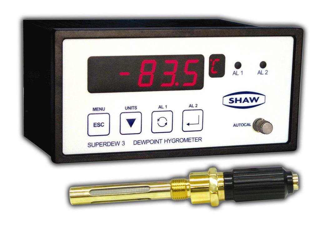
5 General Information 1 AL 1 AL 2 MENU UN IT S AL 1 AL 2 ES C AUT OCAL SUPERDEW 3 DEWPOINT HYGROMETER Every key on the Superdew 3 has two functions, the control function (,, & ) and the Hotkey function (Menu, Units, Alarm 1 and Alarm 2). The use of these commands is described in the table below: The The The The Key Control function Hotkey function Returns the user to the previous screen, Used to enter the setup menu (Menu) key often without changing any variables. by pressing and holding for more than 5 seconds Used to decrease the selected digit Used to enter the Units menu (Units) key (AL 1) key (AL 2) key when setting a numerical variable. Used to select the next digit when setting a numerical variable or to scroll through the options available. Used to confirm a numerical variable or the selection of a chosen option. Used to enter the Alarm 1 menu Used to enter the Alarm 2 menu The Superdew 3 is a DIN style panel mounted moisture monitoring device designed to work in conjunction with the Shaw Sensors. The readout of moisture content is displayed on a backlit, 5-digit, seven segment LED, and available in any one of four selectable engineering units. The selected unit is indicated on a separate seven segment LED. The instrument is available in an AC or DC version. The Superdew 3 operation is controlled by a four-button membrane keypad. The userfriendly software uses a simple menu selection process and incorporates three hot keys to enable moisture levels to be read in different units, and this allows quick access to both alarm settings. A user controllable security system. The Superdew 3 has an autocal potentiometer to perform auto-calibration of sensors. The Superdew 3 has two full range alarms that can be set as rising or falling edge triggered. These alarms have visual indication (LEDs) and activate changeover relays for remote indication or control. The Superdew 3 has a fully controllable linear 4-20mA output. The Superdew 3 also has RS485 capabilities, outputs the process variable and unit status when polled. Details of normal operation, engineering unit selection, and configuration of the instrument are described within this manual. Page 1
6 Safety Information 2 Read the safety information below, before installation. 2.1 Warning Hazardous voltages may be present on instrument terminals. The equipment must be installed by suitably qualified personnel and the instrument must be mounted in a position that provides protection behind the panel to at least IP Isolation The power supply terminals and associated internal circuitry are isolated from all other parts of the equipment in accordance with EN for connection to a category II supply (pollution degree 2). Any terminals or wiring connected to the input or output, which are accessible in normal operation, must only be connected to signals complying with the requirements for Safety Extra Low Voltage (SELV) circuits. The mains supply to the instrument must be protected by an external 1-amp fuse and a suitable switch or circuit breaker, which should be near the instrument. Note: The instrument contains no user serviceable parts. Installation Installing the instrument into a panel Make a cut-out in the donor panel x 68.0mm (DIN 43700). The maximum panel thickness is 8mm. if an effective IP65 weatherproof seal is required, the minimum recommended panel thickness is 2.5mm. Pass the instrument case through the cut-out in the donor panel and attach the two retaining screws to the studs on either side of the case. Tighten the retaining screws onto the back of the donor panel until the instrument is clamped securely in position. The screws must be tightened sufficiently to affect a seal between the front of the donor panel and the back of the instrument bezel, but never over tightened. Page 2
7 3.2 Instrument wiring Wire the Superdew 3 as per figure 1.1 below. Alarm 1 Alarm 2 Coaxial Sensor Connection Zero 4-20mA Output + - A B Com NO C NCNO C NC L N GND GND N LD Power Supply V AC 50/60 Hz Max Power 10VA OR Power Supply 24V DC Max Power 3.3 Power supply The Superdew 3 can be powered by either a V AC or 24V DC supply. Connect the required supply cable to the appropriate terminals as shown in figure 1.1. The AC power supply should be between V 50/60Hz. The power supply wires are retained by screws. Ensure that the exposed section of wire is fully inserted and that no loose strands are exposed. 3.4 Alarm and output cable connectors Connect the required cables to the appropriate terminals as shown in figure 1.1. Note the normally open and normally closed relay contact positions, and that the correct polarity and the maximum load specification are strictly observed for the analogue outputs. Ensure that the wire is fully inserted and that no loose strands are exposed. 3.5 Sensor cable Connect the sensor coaxial cable into the coaxial socket shown in figure 1.1. Route the sensor cable to the intended site of the sensor. Page 3
8 Installing the air/gas sampling system 4 The piping installation schematic diagram (see section 4.1) shows all components that could be used in a dry gas measurement application. Not all the items shown will be required for every installation. Care should be taken to ensure that the sample presented to the measuring sensor is not contaminated with any other component that will damage, contaminate or affect the sensor in a way that will impair the system accuracy. It is strongly recommended that the sample should not contain particulate matter, oil or other heavy hydrocarbon condensate. If these components contaminate the sample system and/or the measuring sensor, the system response time with be lengthened, although the sensor calibration will not be effected. The sample must not contain Ammonia, Chlorine, Ozone or any wet acid vapours or liquid as these will permanently damage the sensor and impair calibration accuracy. The flow rate, although not critical to the sensor measurement, should be low enough to avoid abrasion to the sensor surface without being so low as to extend the system response time to an unacceptable level. In general, a flow rate of between 2 and 3 litres/min at NTP will give the right balance. The sensor is a variable capacitor, which is directly affected by changes in partial pressure of water vapour, and these changes that are proportional to the dew/frost point temperature are displayed on the instrument indicator. The measuring sensor can be installed directly into the process line, but this does create problems with access for maintenance and calibration. It is for these reasons that we recommend that the sensor be installed in a bypass, fast loop or total loss sample system where the sensor is accessible without interrupting the main process flow line. Page 4
9 4.1 Piping installation schematic 4A P Main Process Line 8 4B 9 Notes a. The sample point should be on the upper surface of the horizontal pipe, or from a vertical section of pipe, wherever possible. b. The sample tube should run upwards from the sample point. If this is not possible, then an inspection port or drain tap should be installed at the lowest point in the sample system. 4.2 Piping schematic component index 1) Sample Isolation Valve This is a recommended item as it allows access to the sample system without interrupting the main process line. 2) Sample Tube This should be stainless steel for dry air or gas applications but copper or carbon steel can be used where wetter gases are to be measured. If any section of the sample tube must be flexible then PTFE should be used. In most cases, 3mm OD (1/8 )is sufficient as it provides good system response time within minimum flow. 6mm OD (1/4 ) tube can be used where pressure drops across the 3mm tube are too high. 3) Filter Unit A filter unit is recommended when the samples are likely to contain particulate matter. If the air/gas sample contains heavy hydrocarbon condensate, the filter must be of the coalescing type with a drain. The filter unit should be positioned as close to the sample point as practical. 4) Pressure Reduction Valve or Pressure Regulator If the sample is to be measured at atmospheric pressure then the valve 4A should be fitted and 4B omitted from the system. If the sample is to be measured at full line pressure and the exhaust vented to atmosphere, the valve 4B should be fitted and 4A Page 5
10 omitted from the system. If measurements are to be taken at full line pressure and the sample is to be returned to a part of the main line or vent, which is at a pressure higher than atmospheric, and the input to that line needs a controlled pressure, then both 4A and 4B will be required. 5) Sample Pressure Gauge This is not a critical part of the moisture measurement but may be required if Dew/Frost point measurements are to be made at higher than atmospheric pressure. 6) Measuring Sensor. 7) Sensor Holder. 8) Desiccant Chamber This item is required when the sampling is to be intermittent. When installed, it prevents the ingress of wet air to the sample system while the sample is not flowing, improving the response time. 9) Flow Control Valve This can be a separate item or combined with the flow indicator. 10) Flow Indicator The recommended sample flow is 2 to 3 SL/M. 11) Sample Exhaust The exhaust can be vented to atmosphere or returned to the process line as discussed above. Installing and commissioning the sensor 5 It is advisable to carry out an initial purge routine of the sample loop before installing the sensor. This is to remove the possibility of sensor damage on start-up. Refer to the sample system schematic in section 4.1. Open the inlet isolation valve slowly until a small flow of air/gas (at atmospheric pressure) flows through the inlet pipe work to the sensor holder, exhausting through the sensor entry port of the sensor holder. Allow this purge to continue for about 15 to 20 minutes to remove any residual moisture from the sample pipe work and components. Close the inlet isolation valve and install the sensor into the sensor holder. Locate and connect coaxial cable in position on the sensor. Open the inlet valve slowly, by opening all valves after the sensor holder, allow a low-pressure purge through the whole sample system. (Note: If a closed by-pass loop is installed, this section of the procedure is not possible). Set the required flows within the sample loop. This completes the installation and commissioning, but on initial start-up, it could take several hours for the system to reach equilibrium. The Superdew 3 will now indicate the dewpoint of the air/gas surrounding the sensor, and the analogue output would be giving ma signals proportional to the indicated dewpoint. Page 6
11 Default instrument configuration 6 The standard factory settings are as follows: The instrument will display the moisture content in C Dewpoint Both alarms are set to trigger when rising above the upper limit The output Span is set to 4-20mA The 4-20mA output is set to the full span of the selected range e.g. 4mA = -80 C 20mA = 20 C All security codes are defaulted to 0000 Programming the Superdew Principle of entering numerical data See Appendix A, B & C for flow charts The key allows the user to leave a part of the menu without changing any settings. Wherever a numerical value has to be entered into the Superdew 3 the following text will be found. Use the, & keys to enter. The basic principle used to enter numerical values (integer or floating point) is described here. The first character of the LCD display flashes to indicate it is active. Use the key to select the required number between 0 and 9 (plus the minus sign) then press the key to make the second character flash. Again, use the key to select the required number between 0 and 9, press the key to make the third character flash etc.. Continue this process until all characters are entered. In the case of a floating-point numbers in lb/mmsqf or ppm, pressing the key again makes the decimal point (dp) active. Use the key to position the dp in the required position. Pressing the key at any point confirms the numerical value. ºC & ºF are fixed to 1 dp. Note The Password used within the Superdew 3 is made of four integers and does not use the dp. Note To leave the numerical part of this routine without saving, simply press the key. Configuring the Superdew 3 See Appendix A To enter the Setup Menu press and hold the key for 5 seconds. This will display the SEtUP message on the LED as in the Superdew 3 Setup Menu Flow Diagram (see Appendix A). Pressing the key again enters the setup menu map at the range option on the top level. There are 7 top level options described below: Note: The default set-up will go directly from the SEtUP message to the range screen. However, if the user has set a password, then the user is prompted to enter the correct password before continuing on to the top level. 8 Page 7
12 Note: Most of the screens within the menu have an active 10-second timeout. Therefore, if no keys are pressed within this period the unit reverts automatically to normal operation. In most cases where the 10-second timeout occurs, changes will not have been saved. 8.1 range Description The range option allows the user to select the required sensor range. This option is used to match the Superdew 3 to the sensor connected to the unit. For example a RED sensor requires that the Superdew 3 range option red is selected. Operation While range is displayed press the key to enter the subroutine. The display now shows the currently selected sensor range. Use the key to scroll through the options until the required range is displayed. Press the key to select the new range. The message Conf will be displayed. Press the key again to confirm selection. Note: Pressing the key at any time reverts to the range screen without saving any change. Note: See Superdew 3 Specification for detailed information on ranges. 8.2 outpt Description The outpt option of the Superdew 3 allows the user to set the span and the range over which the 4-20mA operates. The default setting is for the output to cover the full operating span of the selected range e.g. 4mA to equal -100 C and 20mA to equal 0 C. It is possible to set a more focused span, such as 4mA to equal -60 C and 20mA to equal -20 C. It is also possible to select 0-20mA as well as 4-20mA. Operation While outpt is displayed press the key to enter the subroutine. The display now displays SPAn use the key to select either Hi, Lo or SPAn then press the key. Note - If the key is pressed the Superdew 3 will return to the outpt screen. If the SPAn option is selected, use the key to select the required span (0-20mA or 4-20mA). Press the key to confirm selection. If either the Lo or Hi options are selected the screen will now display the current High or Low range value. Use the & keys to enter the new value. Press the key to confirm and save the new value. The other range limit can now be set by following the same process. Note Once the key is pressed to set either the high or low range limit, that value is written to memory and will not revert to the previous value even if the 10-second timeout occurs. 8.3 AL1 & AL2 Description The AL1 & AL2 option allows the user to setup two independent alarms. Trip point, direction of trigger relay enable status, latching status and hysterisis can be set within this option. Operation While AL1 or AL2 are displayed press the key to enter the subroutine. The LED now displays SEtPt. Use the key to select the required function and then press the key. Note: - If the key is pressed the Superdew3 will return to the AL1 or AL2 screen. Page 8
13 Depending on the option selected, the user will now be able to perform the following functions: - SEtPt type relay LAtCh HYSt Enter the alarm set point. Select if the alarm is to activate on a rising signal Hi, falling signal Lo or OFF. Select if the relays are Energised En or de-energised de-en Set if the alarm is Latch YES or not latching no. Enter the hysterisis value. Note Once the key is pressed to set any of the alarm parameter, that value is written to memory and will not revert to the previous value even if the 10 second timeout occurs. 8.4 rs485 (communications) Description The rs485 option allows the user to set the Superdew3 address and communication baud rate used when the Superdew3 is communicating with a PC using RS485 point-to-point communications. Operation While rs485 is displayed press the key to enter the subroutine. The display now displays Addr use the key to select either Addr, or baud then press the key. Note - If the key is pressed the Superdew 3 will return to the rs485 screen. If the Addr option is selected the screen will now display the current address value. Use the & keys to enter the new value. Press the key to confirm and save the new address. Note Once the key is pressed to set the address, that value is written to memory and will not revert to the previous value even if the 10 second timeout occurs. Note Legal addresses are 1 to 32. If the baud option is selected, use the key to select the required baud rate (9600, 4800, 2400 or 1200). Press the key to confirm selection. 8.5 PASS Description The PASS option allows the user to alter the security password used to protect the SetUP menu. Operation While PASS is displayed press the key to enter the subroutine. The LCD now displays Use the, & keys to enter the new password. 8.6 PAnEL Description The PAnEL option allows the user to restrict the functions of the front panel Hotkeys. If the On option is selected, the Hotkeys are unrestricted. Operation While PAnEL is displayed, press the key to enter the subroutine. The LCD now displays On or OFF. Use the key to select On or OFF. Press the key to confirm selection. Page 9
14 Normal operation of the Superdew 3 9 In normal operation, the Superdew 3 will display the current moisture value of the connected sensor. The value is displayed in the currently selected engineering units, which is indicated by the small LED. The Alarm LED s (AL1 & AL2) will light whenever an alarm condition occurs and only turn off when the alarm condition clears. Remote signalling of an alarm condition is provided by two internal changeover relays that trigger at the same time as the LED s. Hotkeys Alarm Keys See Appendix B Description The AL1 & AL2 Hotkeys allow the user to review and alter the Alarm trigger points without interrupting the monitoring process. If the Hotkeys are restricted by the PAnEL function then the alarms can only be reviewed. Operation To review the alarm trip point press the (AL1) or (AL2) key momentarily. The screen will display the set trip point for 2 seconds before reverting to the dewpoint reading. To alter the trip point press and hold the (AL1) or (AL2) keys for longer than 5 seconds. The screen will display and allow the user to alter the trip point using the, & keys 10.2 Units See Appendix C Description The Units Hotkey allows the user to review and alter the displayed units. If the Hotkeys are restricted by the PAnEL function then the units can only be reviewed. If the key is pressed to select another moisture unit, the Superdew3 will display LOC and not change the moisture units. Operation To review the Superdew3 moisture units press the (Units) key for longer than 5 seconds. The screen will display the current moisture reading in the currently selected moisture units. Press the key to scroll through the current moisture level in each of the moisture units. Press the key to select a different moisture unit. Page 10
15 Calibration (Sensor Ranges up to 0 C Dewpoint) 11 A major advantage of the Superdew3 is the Autocal Feature. The system relies on the fact that each sensor is designed to give no further increase in reading when it reaches its maximum moisture level. This means that, for instance, the Silver Spot or Red Spot sensor will read 20ºC Dewpoint when it is exposed to gas at 20ºC Dewpoint, but will continue to read -20ºC Dewpoint when it is exposed to wetter gas. The system can therefore be calibrated very simply by exposing the sensor to anything wetter than 20ºC Dewpoint and adjusting the reading to that point on the display. For the Grey Spot Sensor the maximum level is 0ºC DP and the same principle applies. In practice, an autocal is performed as follows:- 1. Ensure the Superdew3 is powered up. 2. Remove the sensor from the sensor holder and expose it to ambient conditions for at least 1 minute. 3. Check the Superdew3 reading. It should display the maximum level of Dewpoint for the instrument (i.e. 20ºC for Red and 0ºC for Grey). 4. If the unit is reading incorrect then use a small screwdriver to turn the Autocal potentiometer (found on the front panel of the instrument under the knurled cap) clockwise to increase the reading (wetter) or anticlockwise to decrease it. Calibration (Sensor Ranges up to +20 C Dewpoint) 12 In order to calibrate a +20ºC Sensors, it is necessary to measure the ambient air Dewpoint by some other method. Careful use of a sling or whirling hygrometer can achieve accurate results or a cooled mirror device can be used. The following procedure should be used:- 1. Ensure the Superdew3 is powered up. 2. Remove the sensor from the sensor holder and expose it to ambient conditions for at least 1 minute. 3. Compare the reading of the Superdew3 in the ambient air, against the actual moisture level obtained by another method. Turn the Autocal potentiometer (found on the front panel of the instrument under the knurled cap) using a small screwdriver clockwise to increase the reading (wetter) or anticlockwise to decrease it. Monitoring the system 13 The system is designed to operate continuously with a minimum amount of operator input. It is, however, advisable to inspect the sample loop periodically to ensure that the required flows are being maintained. The number and type of items employed in the sample loop will determine what, if any, other routine checks should be made. If, for instance, a filter is used, the filter element should be inspected periodically and changed when necessary. The instrument should not require any routine maintenance, but if any malfunction is suspected, it is advisable to contact your local dealer. Page 11
16 Should it be necessary at any time or for whatever reason, to change either the instrument or sensor, it should be noted that the components of the Superdew 3 sensor system are completely interchangeable. Faults / Errors 14 If the sensor is short-circuited the display will read Short, the voltage output will drive to full scale, the current output will drive to 24mA and both alarms/relays will trip. If the user tries to enter an alarm level above the maximum value of the sensor range selected, the Superdew 3 will display over. Superdew 3 Specification 15 Transmitter: Enclosure: PCB Layout: Compatible with the Shaw Sensor DIN Style, 144mm wide, 72mm high by 116mm deep. General PSU PCB and Display PCB to fit the DIN enclosure. Display: Five characters LED display. Largest positive number Alarm & Range Limits: Upper Limit Lower Limit C Dewpoint F Dewpoint P(PPM) L(lb/MMSCF) Limited to Sensor Range Front Panel: Power Supplies: Alarms: Analogue Outputs: A membrane keyboard with four keys and four windows for the four character LCD, the single character seven segment LED and the two alarm LED s. Universal VAC 50/60hz or 24VDC versions. Two single pole changeover contacts (NO/C/NC), rated at 10A at 240VAC. Alarm trip at set point with 0.1ºC (or equivalent) hysteresis to eliminate relay chatter. Isolated 4-20mA as standard. The span of the outputs can be set by software control. Temperature Range: Electronics -10ºC to +60ºC Sensor -10ºC to +50ºC EMC: Designed to meet the EMC and LVD directives. Page 12

17 Appendix A Superdew 3 Setup Menu Flow Diagram 16 SEtUP PASS Return to Moisture Display Press for > 5 secs 0000 range outpt AL1 AL2 rs485 PASS PAnEL Same As AL1 PUr COnF SPAn 4-20 SEtPt Addr On gr type Lo baud 9600 OFF red Hi Hi 4800 blu Lo OFF 2400 gld relay de-en 1200 YEL En SiL LAtCh no YES HYSt 1.0 (if Password Set) Use & to enter required numerical values


18 Appendix B Alarm 1 & 2 Hotkey Flow Diagram 17 Auto transition


19 Appendix C Units Hotkey Flow Diagram 18
Mark 25 Ultrapure Water Conductivity Analyzer
 Martek Instruments, Inc. Mark 25 Ultrapure Water Conductivity Analyzer Instruction Manual WARRANTY POLICY Unless otherwise stated, MARTEK INSTRUMENTS, INC. warrants this equipment to be free from defects
Carbon Monoxide Transmitter
 Introduction The CO Transmitter uses an electrochemical sensor to monitor the carbon monoxide level and outputs a field-selectable 4-20 ma or voltage signal. The voltage signal may also be set to 0-5 or
VERTEX VT10 SERIES PID OPERATION MANUAL MICROPROCESSOR BASED PID CONTROLLER
 1 VERTEX VT10 SERIES PID OPERATION MANUAL MICROPROCESSOR BASED PID CONTROLLER 1. INTRODUCTION This manual contains information for the installation and operation and tuning of our Vertex VT10 series self-tuning
Analox 1000 Series. User Manual. Analox Sensor Technology Ltd. 15 Ellerbeck Court, Stokesley Business Park North Yorkshire, TS9 5PT, UK
 Analox 1000 Series User Manual Analox Sensor Technology Ltd. 15 Ellerbeck Court, Stokesley Business Park North Yorkshire, TS9 5PT, UK T: +44 (0)1642 711400 F: +44 (0)1642 713900 W: www.analox.net E: info@analox.net
ANALOX SENSOR TECHNOLOGY LTD ANALOX DD1101 INSTALLATION & OPERATION MANUAL
 ANALOX SENSOR TECHNOLOGY LTD ANALOX DD1101 INSTALLATION & OPERATION MANUAL SAFETY WARNING Please Refer to the Safety Warning in Section 7.1 regarding the chemicals in the oxygen sensor Analox Sensor Technology
ANALOX 5001 Carbon Dioxide Monitor. User Manual ANALOX Analox 5001 Carbon Dioxide Monitor User Manual
 ANALOX 5001 ANALOX 5001 Carbon Dioxide Monitor User Manual Analox Sensor Technology Ltd 15 Ellerbeck Court, Stokesley Business Park North Yorkshire, TS9 5PT T: +44 (0)1642 711400 F: +44 (0)1642 713900
Universal Gas Detector
 Universal Gas Detector Instruction Manual PureAire Monitoring Systems, Inc. 557 Capital Drive Lake Zurich, Illinois 60047 Phone: 847-726-6000 Fax: 847-726-6051 Toll-Free: 888-788-8050 pureairemonitoring.com
Table of Contents 1. OVERVIEW SYSTEM LAYOUT SPECIFICATIONS FUNCTION... 11
 Table of Contents 1. OVERVIEW... 3 2. SYSTEM LAYOUT... 4 3. SPECIFICATIONS... 8 3.1 SYSTEM COMPONENTS...9 3.2 PLC INPUTS AND OUTPUTS...9 3.3 FUNCTION KEYS...10 3.4 DEFAULT SET POINTS AND TIMERS...10 4.
Danfoss gas detection units
 Data sheet Danfoss gas detection units Types GD Premium, Premium+, Premium Duplex, Premium Remote, Premium Flex and Premium Uptime The Premium line gas detection units are used for monitoring and warning
Flopurge TS. Operation Manual
 Flopurge TS Operation Manual Part Number 079-0204 Spectron Gas Control Systems United Kingdom Unit 4, Herald Court, University of Warwick Science Park, Coventry, CV4 7EZ +44 (0)24 7641 6234 sales@spectron-gcs.com
Table of Contents SECTION PAGE
 Table of Contents SECTION PAGE SECTION 1 INTRODUCTION................... 1.1 Description.............................. 1.2 Features................................ 1.3 Models.................................
Pump-Down Controller MODEL 4052
 Pump-Down Controller 4-20mA Input/Scalable Output Seal Fail Monitoring Duplex Pump Alternation Hand-Off-Auto Controls Dual Run-time Meters RS-485/Modbus Communications DESCRIPTION The Model 4052 Pump-Down
Danfoss gas detection unit Type GD Heavy Duty
 Data sheet Danfoss gas detection unit Type GD Heavy Duty The Heavy Duty gas detection units are used for monitoring and warning of hazardous Ammonia gas concentrations. They are intended for ATEX/ IECEx
Flostop TS D7E and A8E. Operation Manual
 Flostop TS D7E and A8E Operation Manual United Kingdom Spectron Gas Control Systems Ltd, Unit 4, ATU1, University of Warwick science Park, Coventry, +44 (0) 24 7641 6234 sales@spectron-gcs.com Germany
Series Temperature Controller Instruction Sheet
 Series Temperature Controller Instruction Sheet Thank you very much for purchasing DELTA A Series. Please read this instruction sheet before using your A series to ensure proper operation and please keep
Pump-Up Controller MODEL 4062
 Pump-Up Controller 4-20mA Input/Scalable Output Seal Fail Monitoring Duplex Pump Alternation Hand-Off-Auto Controls Dual Run-time Meters RS-485/Modbus Communications DESCRIPTION The Model 4062 Pump-Up
Duct and Rough Service Carbon Monoxide Sensor
 Product Identification and Overview Duct and Rough Service Carbon Monoxide Sensor BAPI s Carbon Monoxide Sensor offers enhanced electrochemical sensing with outstanding accuracy at low concentrations.
Danfoss gas detection units
 Data sheet Danfoss gas detection units Types GD Premium, Premium+, Premium Duplex, Premium Remote, Premium Flex and Premium Uptime The Premium line gas detection units are used for monitoring and warning
ANALOX 3000 Carbon Monoxide Monitor
 ANALOX 3000 Carbon Monoxide Monitor User Manual Analox Sensor Technology Ltd 15 Ellerbeck Court, Stokesley Business Park North Yorkshire, TS9 5PT T: +44 (0)1642 711400 F: +44 (0)1642 713900 W: www.analox.net
Stand Alone DYNAGARD SP Operation Manual
 Stand Alone DYNAGARD SP Operation Manual Contents Page General Description 1 Detection Principle 1 For Your Safety 1 Design 2 Mounting 2 Mounting Position of DYNAGARD SP 2 Installation of Electrical Connections
INSTALLATION & USER MANUAL
 INSTALLATION & USER MANUAL HC Digital Automatic Humidistat (Y3760) CONTROLS 506808-01 3/2016 Supersedes 6/2011 picture goes here THIS MANUAL MUST BE LEFT WITH THE HOMEOWNER FOR FUTURE REFERENCE NOTICE
eed quality electronic design USER s MANUAL
 eed quality electronic design www.dem-it.com eed www.qeed.it info@qeed.it ANALOG SIGNAL DISPLAY Q-DISP-T USER s MANUAL The displays Q-DISP-T, prepared for mounting on the back panel, 96x48mm, will allow
Air Check O 2 Sample Draw Monitor
 Air Check O 2 Sample Draw Monitor Instruction Manual Part number 99019 without horn, Part number 99029 with horn PureAire Monitoring Systems, Inc. 557 Capital Drive Lake Zurich, Illinois 60047 Phone: 847-726-6000
Tempco Part Number PCT30006 Temperature Control Enclosure with Relay Output for Tote Tank Heating Applications
 Instruction Manual Tempco Part Number PCT30006 Temperature Control Enclosure with Relay Output for Tote Tank Heating Applications Manual PCT30006, Revision 9/20/2016 The PCT30006 control enclosure incorporates
Air Check O 2 Remote Monitor 25%
 Air Check O 2 Remote Monitor 25% Instruction Manual Part number 99087 PureAire Monitoring Systems, Inc. 557 Capital Drive Lake Zurich, Illinois 60047 Phone: 847-726-6000 Fax: 847-726-6051 Toll-Free: 888-788-8050
Air Check O 2 Deficiency Monitor 0-25%
 Air Check O 2 Deficiency Monitor 0-25% Instruction Manual RS-485 Revision 4.05 Part number 99066 PureAire Monitoring Systems, Inc. 557 Capital Drive Lake Zurich, Illinois 60047 Phone: 847-726-6000 Fax:
Remote Vacuum Sensor and Variable Speed Vacuum Pump Control Manual. Version Date - June Part Number
 Innovation In and Out of Parlour Remote Vacuum Sensor and Variable Speed Vacuum Pump Control Manual Version - 1.0 Date - June 2016 Part Number - 39-0038 Index Manual Version... 3 About the Remote Vacuum
Minimal maintenance requirements - No consumables and low cost of ownership. Rapid, accurate results - for safe operation of coal handling systems
 Product Data Sheet CODEL Continuous Mill Fire Detection Coal Mill CO Analyser Low cost, low maintenance devices for continuous monitoring. Robust infrared gas analyser - accurate and reliable operation
OPERATING AND MAINTENANCE MANUAL. for the G30 CARBON DIOXIDE MONITOR
 OM117 OPERATING AND MAINTENANCE MANUAL for the G30 CARBON DIOXIDE MONITOR (Part No: G30) (Intentionally Blank) APPROVAL SHEET DIVEX MANUAL NUMBER: ADVITIUM NUMBER: DOCUMENT TITLE: OM117 GA-OM-5715 G30
Analog Room Pressure Monitor RPC Series
 Description The Room Pressure Monitor is used to measure differential pressure in the range of 0.125 to 1"wc or 30 to 250 Pa. It combines precision high sensitivity silicon sensing capabilities and the
Nov 08 PRODUCT SPECIFICATION SHEET
 Honeywell UDC1200 and UDC1700 MICRO-PRO SERIES UNIVERSAL DIGITAL CONTROLLERS 51-52-03-35 Nov 08 PRODUCT SPECIFICATION SHEET OVERVIEW The UDC1200 & UDC1700 are microprocessor-based 1/16 DIN and 1/8 DIN
Digi-Sense TC9000 Advanced PID and On/Off Temperature Controller with Thermocouple Input
 User Manual 99 Washington Street Melrose, MA 02176 Phone 781-665-1400 Toll Free 1-800-517-8431 Visit us at www.testequipmentdepot.com Digi-Sense TC9000 Advanced PID and On/Off Temperature Controller with
RS Pro Infrared Temperature Sensor
 Instruction Manual RS Pro Infrared Temperature Sensor Stock Number: 161-8103 Introduction The RS Pro Infrared Temperature Sensor is a device for measuring the temperature of the surface of a solid or liquid
AutomationDirect PM24. Microprocessor - Based Process/Temperature Limit Controller. Operator s Manual. Technical Support.
 AutomationDirect 1/16 DIN Series Technical Support We strive to make our manuals the best in the industry. We rely on your feedback to let us know if we are reaching our goal. If you cannot find the solution
WD-CS. Water leak detection cable. Technical Overview. Features. Page 1. Data Sheet Ref: Issue: 5.1.
 Data Sheet Ref: 90501085 WD-CS Water leak detection cable Technical Overview The WD-CS range of cable sensors are typically used to detect water leaks usually under floors, and are used in conjunction
P R O D U C T S P E C I F I C A T I O N MSA Ultima X Series Sensor/Transmitter Specification
 P R O D U C T S P E C I F I C A T I O N MSA Ultima X Series Sensor/Transmitter Specification 1.0 This specification details the attributes and operating characteristics of the MSA Ultima X Series sensors/transmitters.
Software Version 2.01 LEVEL MONITOR MODEL 220
 Software Version 2.01 LEVEL MONITOR MODEL 220 19 April 2000 CONTENTS 1. Introduction 1 1.1 Model Number Designation 2 1.2 Intrinsic Safety Considerations 3 2. Specification 4 3. Operation 6 3.1 Display
Two-Channel Gas Controller
 Two-Channel Gas Controller Specifications subject to change without notice. USA 09 Page of DESCRIPTION Highly configurable, UL 0 performance-tested and -certified, and wall-mounted gas monitor; continuously
Product Manual SZ1145
 Product Manual SZ114 General Purpose Monitor Communicating Controls Description The SZ114 is a microprocessor-based monitoring and alarm interface designed to monitor up to four 1000 Ω platinum temperature
S304 and S305 Dust Emission Monitors. User Manual. Distributor
 S304 and S305 Dust Emission Monitors User Manual Distributor Version 6.4 30/5/2012 Table of Contents 1. INTRODUCTION... 3 1.1 Safety... 3 1.2 Product overview... 4 1.3 Principle of operation... 4 2. INSTALLATION...
HP727S. Single speed swimming pool heat pump controller Operation manual TABLE OF CONTENTS
 HP727S Single speed swimming pool heat pump controller Operation manual TABLE OF CONTENTS 1. General Description 2. Specifications 3. Installation Instructions 4. Electrical Wiring 5. Instrument Wiring
Frequently asked questions: Intelligent Transmitter Series
 Frequently asked questions: Intelligent Transmitter Series The Wilcoxon family of Intelligent Transmitters, relay alarms, and communication modules can be used to implement low-cost online vibration monitoring
SIMPLICITY CO CARBON MONOXIDE DETECTION & VENTILATION PANEL
 SIMPLICITY CO CARBON MONOXIDE DETECTION & VENTILATION PANEL USER MANUAL 1 Table of Contents 1 SAFETY INFORMATION...3 1.1 SAFETY PRECAUTIONS DURING NORMAL OPERATION OF PANEL...3 1.3 BATTERY INFORMATION...3
PTE0705 Electric Fence Monitor
 PTE0705 Electric Fence Monitor The JVA logo is a registered trademark of JVA Technologies. JVA Technologies. TABLE OF CONTENTS DESCRIPTION... 2 QUICK START GUIDE... 3 FEATURES... 4 EXPLANATION OF TERMS...
TYPE CM-2201 NELSON SINGLE POINT CIRCUIT MANAGEMENT SYSTEM
 2 Line, 16 Characters/row LCD Display Temperature Input Range -50 C to +500 C -58 F to + 932 F Enclosure NEMA Type 4X Current Rating 30A max (resistive load only) Ambient Temperature -40 C to + 40 C -40
Beacon 200 Gas Monitor Operator s Manual. Part Number: RK Released: 6/6/08
 Beacon 200 Gas Monitor Operator s Manual Part Number: 71-2102RK Released: 6/6/08 Table of Contents Chapter 1: Introduction.................................................3 Overview.............................................................3
1 4 DIN Dissolved Oxygen Controller
 16. Warranty OAKTON warrants this controller to be free from significant deviations in material and workmanship for a period of one year from date of purchase. If repair or adjustment is necessary and
Pakton Technologies Pty Ltd ABN Ferrier Road, Narangba Qld 4504
 Remote Monitor PTE0700 SECURITY ELECTRONICS User Manual PTE0700 V2 Series Remote Monitor Pakton Technologies Pty Ltd ABN 66 405 694 842 16 Ferrier Road, Narangba Qld 4504 PO Box 408, Narangba QLD 4504
FLOW CONTROLLER TYPE S/601
 Checked Version Release date QA V4.2.6 F1 F2 EN 26.01.2012 Manual FLOW CONTROL FLOW CONTROLLER TYPE S/601 MODELS F1 AND F2 INTRODUCTION Thank you for using the S/601 flow and batch control series. This
Digital Gas Transmitters with Auxiliary Inputs & Control. PolyGard 2 DC6
 Digital Gas Transmitters with Auxiliary s & Control Specifications subject to change without notice. USA 181011 Page 1 of 5 DESCRIPTION Digital RS-485 communicating, addressable toxic and combustible gas
BS-316. Gas detection control panel up to 16 inputs. Installation operation manual
 BS-316 Gas detection control panel up to 16 inputs Installation operation manual Page 1 from 21 Contents 1 Operation instructions--------------------------------------------------------------------------------------------------------------------3
PureAire Combo O 2 / CO 2 Monitor
 PureAire Combo O 2 / CO 2 Monitor Instruction Manual PureAire Monitoring Systems, Inc. 557 Capital Drive Lake Zurich, Illinois 60047 Phone: 847-726-6000 Fax: 847-726-6051 Toll-Free: 888-788-8050 pureairemonitoring.com
GG-2 2-CHANNEL GAS DETECTION CONTROL PANEL. Installation and Operation Manual
 GG-2 2-CHANNEL GAS DETECTION CONTROL PANEL Installation and Operation Manual 2 GG-2 Warning Use this product only in the manner described in this manual. If the equipment is used in a manner not specified
RAM 50 Series Operation Manual
 RAM 50 Series Operation Manual Worldwide Manufacturer of Gas Detection Solutions Table of Contents Page Introduction... 3 Detection Principle... 3 Overview... 3 Description... 4 Switches... 4 Indicators...
Nitrogen Dioxide (NO2) Single-Point Gas Detection System
 Single-Point Gas Detection System") Nitrogen Dioxide (NO) Single-Point Gas Detection System DESCRIPTION Wall-mounted gas monitor with built-in nitrogen dioxide (NO)/diesel fume gas sensor, accepts one analog remote device such as a secondary
Nitrogen Dioxide (NO) Single-Point Gas Detection System DESCRIPTION Wall-mounted gas monitor with built-in nitrogen dioxide (NO)/diesel fume gas sensor, accepts one analog remote device such as a secondary
User Manual. Digi-Sense TC9500 Advanced Multiparameter Temperature Controller with Thermocouple, Thermistor, and RTD Inputs
 User Manual Digi-Sense TC9500 Advanced Multiparameter Temperature Controller with Thermocouple, Thermistor, and RTD Inputs Models 89800-03 and 89800-04 THE STANDARD IN PRECISION MEASUREMENT Table of Contents
Product Manual SZ1144
 Product Manual SZ1144 Refrigeration Temperature Monitor Communicating Controls Description The SZ1144 is a microprocessor-based monitoring and alarm interface designed to monitor up to four 1000 Ω platinum
Air Check O 2 Sample Draw Monitor
 Air Check O 2 Sample Draw Monitor Instruction Manual PureAire Monitoring Systems, Inc. 557 Capital Drive Lake Zurich, Illinois 60047 Phone: 847-726-6000 Fax: 847-726-6051 Toll-Free: 888-788-8050 pureairemonitoring.com
Instructions for the fan motor control system, SILVER C
 Instructions for the fan motor control system, SILVER C 1. General The motor control system is used for controlling the type EC, 0.41-10 kw fan motors in the SILVER C units. The motor control system is
TC515 and TC600 Installation Manual. a Winters company
 THERMOLINE TEMPERATURE CONTROLLERS TC515 and TC600 Installation Manual a Winters company Guarantee 12 months Congratulations on the purchase of this new product. Special care with the design, workmanship
RAM 50 Series Operation Manual
 RAM 50 Series Operation Manual Worldwide Manufacturer of Gas Detection Solutions TABLE OF CONTENTS Page Introduction... 3 Principles of operation... 3 Overview... 4 Description... 4 Installation... 7
Air Check Ex O 2 Deficiency Monitor
 Air Check Ex O 2 Deficiency Monitor Instruction Manual Part number 99020 PureAire Monitoring Systems, Inc. 1140 Ensell Road Lake Zurich, Illinois 60047 Phone: 847-726-6000 Fax: 847-726-6051 Toll-Free:
DC VOLTMETER DCV-10 / 10A / 10C / 10S / 10CS / 11 / 11A / 11C / 11S / 11CS. A4741 / Rev.1
 DC VOLTMETER DCV-10 / 10A / 10C / 10S / 10CS / 11 / 11A / 11C / 11S / 11CS User Manual and Menu Map A4741 / Rev.1 www.entes.com.tr ATTENTION -Disconnect all power before connecting the device. -Don t remove
TEMPERATURE CONTROLLER (STANDARD MODEL)
") OPERATING MANUAL TEMPERATURE CONTROLLER (STANDARD MODEL) 689-0000 689-0005 Barnant Company 28W092 Commercial Avenue Barrington, Illinois U.S.A. 60010-2392 (847) 381-7050 (847) 381-7053 (Fax) 800-637-3739
OPERATING MANUAL TEMPERATURE CONTROLLER (STANDARD MODEL) 689-0000 689-0005 Barnant Company 28W092 Commercial Avenue Barrington, Illinois U.S.A. 60010-2392 (847) 381-7050 (847) 381-7053 (Fax) 800-637-3739
Air Check O 2 Deficiency Monitor 0-25%
 Air Check O 2 Deficiency Monitor 0-25% Instruction Manual For model KF-25 Part number 99035 PureAire Monitoring Systems, Inc. 557 Capital Drive Lake Zurich, Illinois 60047 Phone: 847-726-6000 Fax: 847-726-6051
User Guide. DATUM L150 Panel-Mounted Universal Level Indicator A1. ABB Instrumentation
 User Guide DATUM L150 Panel-Mounted Universal Level Indicator DATUM L150 2145.3A1 A2 A3 ABB Instrumentation Use of Instructions Warning. An instruction that draws attention to the risk of injury or death.
SAPCON SMART-SSI. Continuous Speed Indicator. Users Manual. . Introduction. . General Description. . Principle of Operation. .
 CALIB CONTINUOUS SPEED INDICATOR EVALUATION UNIT ALRM 1 ALRM 2 ALRM 3 PULSE DISPLAY MESSAGES INSTRUMENT START/RESTART OVERSPEED OCCURED > UNDERSPEED OCCURED < SPEED IS
Tempco PCT-3000 Series Temperature Control Console with Relay Output for Heating or Cooling Applications
 Instruction Manual Tempco PCT-3000 Series Temperature Control Console with Relay Output for Heating or Cooling Applications Manual PCT-3000 Revision 9/2014 The PCT-3000 series control console incorporates
GLD-30 Gas Leak Detector
 GLD-30 Gas Leak Detector Installation, Operation & Maintenance General: The Archer Instruments GLD-30 is an ambient air monitor, used to detect the presence of a target gas (or gases) and to alert operators
ANALOX 101 D2 PORTABLE OXYGEN MONITOR USER MANUAL
 ANALOX 101 D2 PORTABLE OXYGEN MONITOR USER MANUAL Analox Sensor Technology Ltd 15 Ellerbeck Court Stokesley Business Park Stokesley TS9 5PT Tel: +44 (0)1642 711400 Fax: +44 (0)1642 713900 Email: info@analox.net
ENMET 680 Fairfield Court Ann Arbor, MI Fax LC-8 Controller Operation and Maintenance Manual
 680 Fairfield Court Ann Arbor, MI 48108 734.761.1270 Fax 734.761.3220 www.enmet.com LC-8 Controller Operation and Maintenance Manual Table of Contents 1.0 INTRODUCTION... 2 1.1 Unpack... 2 1.2 Check Order...
Interscan Corporation. Instruction Manual Series Compact Portable Analyzer
 Interscan Corporation Instruction Manual 4000 Series Compact Portable Analyzer 1 2 INTERSCAN CORPORATION Simplified 4000 SERIES MANUAL TABLE OF CONTENTS SECTION TITLE PAGE 1.0 Equipment Description 4 2.0
VT4810 SINGLE / DUAL ZONE CONTROLLER INSTALLATION MANUAL
 Thermocouple Type BS4937 (IEC584-3): Outer / + / - BS1843 (Old UK Standard) Outer / + / - US Outer / + / - J : Iron / Copper-Nickel Black / Black / White Black / Yellow / Blue Black / White / Red VT4810
GASGUARDIAN Channel Controller OPERATING & INSTALLATION MANUAL
 GASGUARDIAN 2 3 2-Channel Controller OPERATING & INSTALLATION MANUAL GasGuardian 2 3 Operating and Installation Manual Table of Contents General description.... 3 Installation. 3 Locating the GasGuardian-2..
CT224 Setup Tutorial
 CT224 Setup Tutorial Table of Contents 1. Introduction 2. Configuring Controller for Operation A. Example 1 Over Temp Operation with Hysteresis @ 5º F. B. Example 2 Under Temp Operation with Hysteresis
User Manual. PolyGard Gas Controller MGC3. Two-Channel Analog Gas Controller Serial Number _E _0907. September 2007
 PolyGard Gas Controller MGC3 Two-Channel Analog Gas Controller Serial Number _E _0907 User Manual September 2007 January 04, 2016 Revision Specifications subject to change without notice. USA 160104 Page
LINEAR HEAT DETECTION CABLE DURÁN-SAFE
 LINEAR HEAT DETECTION CABLE DURÁN-SAFE Installation & User Manual 2018 DURAN ELECTRONICA S.L. - All rights reserved www.duranelectronica.com I-manSAFECABLE-v05 TABLE OF CONTENTS Pages 1. INTRODUCTION...
Low Temperature Zirconia Oxygen Analyzer
 Data Sheet SS/ZDT FG Issue 10 Low Temperature Zirconia Oxygen Analyzer ZDT FG Environmental certification MCERTS SIRA certificate MC99000 1/00 User-friendly language options selectable system alarms comprehensive
SCAN200E USER S MANUAL
 SCAN200E USER S MANUAL Code No. 2071 1052 rev. 1.4 Code No. 2071 1052 Rev. 1.4 Page 2/16 SCAN200E User s Manual Foreword This manual is for SCAN200E Controller running software version 2.03 or later. We
Instructions for the fan motor control system with integrated wiring terminals SILVER C
 Instructions for the fan motor control system with integrated wiring terminals SILVER C 1. General The motor control system is used for controlling the type EC, 0.41-10 kw fan motors in the SILVER C units.
Pioneer-R16 Gas Monitor Operator s Manual
 Pioneer-R16 Gas Monitor Operator s Manual Edition 7/2/97 RKI INSTRUMENTS, INC RKI Instruments, Inc. 33248 Central Ave, Union City, CA 94587 (510) 441-5656 Chapter 1: Description About the Pioneer-R16 Gas
Wallace & Tiernan Controllers & Analysers ChemTrim Disinfection Controller
 Wallace & Tiernan s & Analysers ChemTrim Disinfection Introduction The ChemTrim Disinfection is a modern, dedicated controller incorporating the latest advanced electronics and process control application
DPR-145 TEMPERATURE PROTECTION RELAY. DPR-145 User Manual V-2.0 ( ) PT100 INPUTS: 4 RELAY OUTPUTS: 4 RS-485 MODBUS PORT VDC SUPPLY -1-
 PT100 INPUTS: 4 RELAY OUTPUTS: 4 RS-485 MODBUS PORT VDC SUPPLY -1-") DPR-45 User Manual V-2.0 (2..206) DPR-45 TEMPERATURE PROTECTION RELAY PT00 INPUTS: 4 RELAY OUTPUTS: 4 RS-485 MODBUS PORT 9-50VDC SUPPLY DESCRIPTION DPR-45 is a precision unit designed for the temperature
DPR-45 User Manual V-2.0 (2..206) DPR-45 TEMPERATURE PROTECTION RELAY PT00 INPUTS: 4 RELAY OUTPUTS: 4 RS-485 MODBUS PORT 9-50VDC SUPPLY DESCRIPTION DPR-45 is a precision unit designed for the temperature
Air Check O 2 Deficiency Monitor
 Air Check O 2 Deficiency Monitor Instruction Manual PureAire Monitoring Systems, Inc. 557 Capital Drive Lake Zurich, Illinois 60047 Phone: 847-726-6000 Fax: 847-726-6051 Toll-Free: 888-788-8050 pureairemonitoring.com
Operating Instructions
 Operating Instructions System 57 5701 CONTROL SYSTEM OPERATING INSTRUCTIONS Helping to make a safer world Ensure that you read and understand these instructions BEFORE operating the equipment. Please pay
DIGITAL METERS Large Display Temperature Meters Instruction Manual
 DIGITAL METERS Large Display Temperature Meters PD755 PD756 PD757 Handles Thermocouple & RTD Inputs with Simplicity J, K, T, E, R, & S Thermocouples 100 Ω Platinum RTD (0.00385 or 0.00392 curve) Large
SMART EVO 2 - User Manual ELECTRICAL PANEL FOR 2 MOTORS
 SMART EVO 2 - User Manual ELECTRICAL PANEL FOR 2 MOTORS CONTENTS 1. INTRODUCTION... 5 2. WARNINGS... 6 3. GENERAL DESCRIPTION... 7 4. INSTALLATION... 8 5. LUMINOUS INDICATORS AND COMMANDS... 9 6. DIP-SWITCH
LC-Series Controller 1-4 Channel Operation and Maintenance Manual
 680 Fairfield Court Ann Arbor, MI 48108 734.761.1270 Fax 734.761.3220 www.enmet.com LC-Series Controller 1-4 Channel Operation and Maintenance Manual Table of Contents 1.0 INTRODUCTION... 2 1.1 Unpack...
RE-PR3-E-27 3-Phase Panel Mount 27kW
 Page 1 of 6 RE-PR3-E-27 3-Phase Panel Mount 27kW Features: Benefits: 0-10Vdc, 0-5Vdc, 4-20mA or manual via potentiometer control input Over temperature protection with auto reset Enclosed panel mounting
BC3250. Blowdown Controller
 Local regulations may restrict the use of this product to below the conditions quoted. In the interests of development and improvement of the product, we reserve the right to change the specification without
Installation Manual Tracker 221
 Installation Manual Tracker 221 KSR KUEBLER AG Im Kohlstatterfeld 17 D-69439 Zwingenberg / Germany www.ksr-kuebler.com Contents About this Installation Manual...4 Description Tracker 220-series...4 Installing
10yr O2NE & Safe-Ox. User Manual
 Analox Ltd. 15 Ellerbeck Court, Stokesley Business Park North Yorkshire, TS9 5PT, UK T: +44 (0)1642 711400 F: +44 (0)1642 713900 W: www.analox.net E: info@analox.net This support line is closed on UK public
REGARD. REGARD 4-20 AND Ex CHANNEL CARDS INSTALLATION AND OPERATING MANUAL (FOR ATEX VERSION CARDS)
") REGARD REGARD 4-20 AND Ex CHANNEL CARDS INSTALLATION AND OPERATING MANUAL (FOR ATEX VERSION CARDS) Part No. 4206712 For use with Regard 4-20 and Ex cards software version 3.0 or later. Draeger Safety UK
REGARD REGARD 4-20 AND Ex CHANNEL CARDS INSTALLATION AND OPERATING MANUAL (FOR ATEX VERSION CARDS) Part No. 4206712 For use with Regard 4-20 and Ex cards software version 3.0 or later. Draeger Safety UK
Syncro AS. Analogue Addressable Fire Control Panel. User Manual
 Syncro AS Analogue Addressable Fire Control Panel User Manual Man-1100 Issue 02 Nov. 2008 Index Section Page 1. Introduction...3 2. Safety...3 3. Panel Controls...4 3.1 Access Level 1...4 3.2 Access Level
Toxic Gas Detection. Model F12. Toxic Gas Detection
 Toxic Gas Detection Model F12 Toxic Gas Detection Smart Sensor Technology The Series F12 Gas Transmitter is an Intrinsically Safe (IS) version of our explosion-proof D12 transmitter. In its standard form,
Dipl.-Ing. W. Bender GmbH & Co. KG Londorfer Str Grünberg Phone: Fax:
 Dipl.-Ing. W. Bender GmbH & Co. KG Londorfer Str. 5 35305 Grünberg Phone: 040 807-0 Fax: 040 807-259 Alarm indicator and test combination MK2430 Remote alarm indicator and test combination with LC display
Models 4623, 4628 & 5999/980 USP<645> Conductivity Analyzers
 Data sheet USP Conductivity Analyzers A conductivity system designed to meet USP for the Pharmaceutical Industry incorporating automatic Stage 1 test Meets USP requirements ensures compliance
Water Detection Controllers
 Page 1 of 5 Water Detection Controllers Features: Benefit: LED Status of leak status VFC output Audible alarm Auto or manual reset alarm output Uses an isolated AC signal which prevents oxidation or erosion
Interactive Fire Control Panel IFS7002 four signal loops Instruction Manual
 Interactive Fire Control Panel IFS7002 four signal loops Instruction Manual Revision 6/01.17 Contents 1. Introduction... 6 2. Terminology... 6 3. Function... 8 4. Technical data... 8 4.1. Physical configuration...
ZXe INTELLIGENT MULTI PROTOCOL FIRE ALARM CONTROL PANEL
 ZXe INTELLIGENT MULTI PROTOCOL FIRE ALARM CONTROL PANEL PRODUCT Specification FEATURES Designed To Meet The Requirements Of EN54 Expandable From 1 To 5 Loops As Standard A Variety Of Networking Options