Technical Committee on Sprinkler System Installation Criteria
|
|
|
- May Norman
- 5 years ago
- Views:
Transcription
1 Technical Committee on Sprinkler System Installation Criteria M E M O R A N D U M DATE: May 30, 2017 TO: FROM: Principal and Alternate Members of the Technical Committee on Sprinkler System Installation Criteria Dave Hague, Principal Fire Protection Engineer/NFPA Staff Liaison SUBJECT: AUT-SSI AGENDA PACKAGE A2018 Second Draft Meeting Enclosed is the agenda for the Second Draft meeting for NFPA 13, Standard for the Installation of Sprinkler Systems. NFPA 13 has entered the Annual 2018 revision cycle and will produce a 2019 Edition. It is imperative that you review the attached public comments in advance, with your ideas and substantiations for your views. If you have alternate suggestions for text changes, please come prepared with the words and respective substantiation. For administrative questions, please feel free to contact Elena Carroll at (617) For technical questions, please feel free to contact Dave Hague at (617) You can also reach either of us via at ECarroll@nfpa.org or dhague@nfpa.org. We look forward to meeting everyone in Raleigh, NC at the Renaissance Raleigh North Hills Hotel. 1
2 Table of Contents Part 1 - Meeting Agenda Part 2 - Committee Address List Part 3 New Process Worksheets Part 4 A2018 First Draft Meeting Minutes Part 5 - A2018 Key Dates Part 6- SSI Public Comments 2
3 PART 1 MEETING AGENDA 3
4 Technical Committee on Sprinkler System Installation Criteria Second Draft Meeting June 26-27, 2017 Renaissance Raleigh North Hills Hotel 4100 Main at North Hills Street Raleigh, NC AGENDA Monday June 26, Call to Order 8:00 AM 2. Introductions of Members and Staff 3. Review and Approval of A2018 First Draft Meeting Minutes 4. Review of A2018 Revision Cycle and Meeting Schedule 5. Review of Distributed Material and Workload b. Overview of Public Comments c. Overview of Potential Committee Second Revisions 6. Review Public Comments Tuesday, June 27, Reconvene 8:00AM (Time Subject to Change) 8. Adjournment TBD 4
5 PART 2 COMMITTEE ADDRESS LIST 5
6 Address List No Phone Sprinkler System Installation Criteria Automatic Sprinkler Systems Raymond A. Grill Chair Arup 1120 Connecticut Avenue, NW, Suite 1110 Washington, DC SE 12/08/2015 AUT-SSI Roland A. Asp Principal National Fire Sprinkler Association, Inc. 514 Progress Drive, Suite A Linthicum, MD National Fire Sprinkler Association Design Technician Alternate: Jeffrey A. Hewitt 05/25/2017 David R. Hague AUT-SSI M 07/29/2013 AUT-SSI Hamid R. Bahadori Principal JENSEN HUGHES 725 Primera Boulevard, Suite 215 Lake Mary, FL Alternate: LeJay Slocum SE 4/17/1998 AUT-SSI Weston C. Baker, Jr. Principal FM Global 1151 Boston Providence Turnpike PO Box 9102 Norwood, MA Alternate: Angele Morcos I 9/30/2004 AUT-SSI Cecil Bilbo, Jr. Principal Academy of Fire Sprinkler Technology, Inc. 301 North Neil Street, Suite 423 Champaign, IL Alternate: Mark G. Karr SE 7/26/2007 AUT-SSI Pat D. Brock Principal Oklahoma State University Fire Protection & Safety Technology 1424 West Liberty Avenue Stillwater, OK Alternate: Floyd Luinstra SE 8/5/2009 AUT-SSI Robert G. Caputo Principal Fire & Life Safety America East Camacho Road Queen Creek, AZ IM 1/16/1998 AUT-SSI Scott T. Franson Principal The Viking Corporation 210 North Industrial Park Road Hastings, MI National Fire Sprinkler Association Manufacturer Alternate: David L. Asplund M 10/29/2012 AUT-SSI Jeff Hebenstreit Principal UL LLC 484 Tamarach Drive Edwardsville, IL Alternate: Kerry M. Bell RT 08/11/2014 AUT-SSI Luke Hilton Principal Liberty Mutual Property Ballantyne Corporate Place, Suite 525 Charlotte, NC Alternate: Glenn E. Thompson I 1/18/2001 AUT-SSI Elwin G. Joyce, II Principal Eastern Kentucky University 2148 Alexandria Drive Lexington, KY NFPA Industrial Fire Protection Section U 10/10/1997 AUT-SSI Larry Keeping Principal PLC Fire Safety Solutions 3413 Wolfedale Road, Suite 6 Mississauga, ON L5C 1V8 Canada SE 10/10/1997 AUT-SSI 6 1
7 Address List No Phone Sprinkler System Installation Criteria Automatic Sprinkler Systems John Kelly Principal Washington DC Fire & EMS Department Office of the Fire Marshal 719 Opus Avenue Capitol Heights, MD E 08/09/2012 AUT-SSI 05/25/2017 David R. Hague AUT-SSI Charles W. Ketner Principal National Automatic Sprinkler Fitters LU 669 Joint Apprenticeship & Training Committee 7050 Oakland Mills Road Columbia, MD United Assn. of Journeymen & Apprentices of the Plumbing & Pipe Fitting Industry Alternate: Michael A. Rothmier L 1/10/2008 AUT-SSI Russell B. Leavitt Principal Telgian Corporation S. 50th Place Phoenix, AZ Telgian Corporation Alternate: Ralph E. Bless, Jr. SE 04/05/2016 AUT-SSI Kenneth W. Linder Principal Swiss Re 2 Waterside Crossing, Suite 200 Windsor, CT Alternate: Todd A. Dillon I 1/1/1984 AUT-SSI David O. Lowrey Principal City of Boulder Fire Rescue 3065 Center Green Drive Boulder, CO E 08/09/2012 AUT-SSI Rodney A. McPhee Principal Canadian Wood Council 99 Bank Street, Suite 400 Ottawa, ON K1P 6B9 Canada Alternate: Dennis A. Richardson U 10/10/1997 AUT-SSI Michael F. Meehan Principal VSC Fire & Security 1417 Miller Store Road, Suite C Virginia Beach, VA American Fire Sprinkler Association Design Alternate: E. Parks Moore IM 1/16/1998 AUT-SSI Joe W. Noble Principal Noble Consulting Services, LLC 6345 South Jones Blvd., #100 Las Vegas, NV International Fire Marshals Association E 10/10/1997 AUT-SSI Thomas A. Noble Principal City of North Las Vegas Floragold Court Las Vegas, NV E 8/5/2009 AUT-SSI Steven J. Scandaliato Principal SDG, LLC Pilgrim Hall Drive Friendswood, TX SE 10/03/2002 AUT-SSI Peter T. Schwab Principal Wayne Automatic Fire Sprinklers, Inc. 222 Capitol Court Ocoee, FL Alternate: Ryan Peterson IM 3/15/2007 AUT-SSI Adam Seghi Principal Coda Risk Analysis 9624 Vista View Drive Austin, TX I 10/29/2012 AUT-SSI 7 2
8 Address List No Phone Sprinkler System Installation Criteria Automatic Sprinkler Systems Austin L. Smith Principal Consolidated Nuclear Security, LLC, Y Bear Creek Road, MS 8107 PO Box 2009 Oak Ridge, TN Alternate: William Overton U 3/1/2011 AUT-SSI William B. Smith Principal Code Consultants, Inc Woodland Parkway, Suite 300 St. Louis, MO Alternate: David J. Burkhart 05/25/2017 David R. Hague AUT-SSI SE 10/27/2005 AUT-SSI Paul A. Statt Principal Eastman Kodak Company 41 Monaco Drive Rochester, NY U 1/10/2008 AUT-SSI Zeljko Sucevic Principal Vipond Fire Protection 6380 Vipond Drive Mississauga, ON L6M 3C1 Canada Canadian Automatic Sprinkler Association Alternate: Jason W. Ryckman IM 08/09/2012 AUT-SSI Terry L. Victor Principal Tyco/SimplexGrinnell 3621 Carrollton Road Upperco, MD Alternate: Manuel Silva M 10/3/2002 AUT-SSI Robert Vincent Principal Shambaugh & Son, L.P Opportunity Drive Fort Wayne, IN National Fire Sprinkler Association Contractor Alternate: James A. Charrette IM 4/3/2003 AUT-SSI Daniel P. Wake Principal Victaulic Company of America 4901 Kesslersville Road PO Box 31 Easton, PA Alternate: Ahmed Saleh M 08/09/2012 AUT-SSI Thomas G. Wellen Principal American Fire Sprinkler Association, Inc Merit Drive, Suite 350 Dallas, TX American Fire Sprinkler Association Installer/Maintainer Alternate: Jason Gill IM 04/05/2016 AUT-SSI David L. Asplund Alternate Reliable Automatic Sprinkler Company, Inc Smith Grove Road Liberty, SC National Fire Sprinkler Association Manufacturer Principal: Scott T. Franson M 08/03/2016 AUT-SSI Kerry M. Bell Alternate UL LLC 333 Pfingsten Road Northbrook, IL Principal: Jeff Hebenstreit RT 4/15/2004 AUT-SSI Ralph E. Bless, Jr. Alternate Telgian Corporation 900 Circle 75 Parkway, Suite 680 Atlanta, GA Telgian Corporation Principal: Russell B. Leavitt SE 04/04/2017 AUT-SSI David J. Burkhart Alternate Code Consultants, Inc Woodland Parkway, Suite 300 St. Louis, MO Principal: William B. Smith SE 03/07/2013 AUT-SSI 8 3
9 Address List No Phone Sprinkler System Installation Criteria Automatic Sprinkler Systems James A. Charrette Alternate Allan Automatic Sprinkler of So. California 3233 Enterprise Street Brea, CA National Fire Sprinkler Association Contractor Principal: Robert Vincent IM 7/26/2007 AUT-SSI Todd A. Dillon Alternate Global Asset Protection Services, LLC 1620 Winton Avenue Lakewood, OH Principal: Kenneth W. Linder 05/25/2017 David R. Hague AUT-SSI I 7/16/2003 AUT-SSI Jason Gill Alternate Fire & Life Safety America 3017 Vernon Road, Suite 100 Richmond, VA American Fire Sprinkler Association Installer/Maintainer Principal: Thomas G. Wellen IM 04/05/2016 AUT-SSI Jeffrey A. Hewitt Alternate American Fire Protection, Inc Eastcliff Industrial Loop Birmingham, AL National Fire Sprinkler Association Design Technician Principal: Roland A. Asp M 10/29/2012 AUT-SSI Mark G. Karr Alternate Academy of Fire Sprinkler Technology, Inc. 301 North Neil Street, Suite 426 Champaign, IL Principal: Cecil Bilbo, Jr. SE 10/28/2014 AUT-SSI Floyd Luinstra Alternate Oklahoma State University 499 Cordell South Stillwater, OK Principal: Pat D. Brock SE 10/29/2012 AUT-SSI E. Parks Moore Alternate S & S Sprinkler Company, LLC PO Box 7453 Mobile, AL American Fire Sprinkler Association Design Principal: Michael F. Meehan IM 04/05/2016 AUT-SSI Angele Morcos Alternate FM Global 1151 Boston-Providence Turnpike Norwood, MA Principal: Weston C. Baker, Jr. I 12/08/2015 AUT-SSI William Overton Alternate Consolidated Nuclear Security, LLC, Y-12 PO Box 2009, MS 8107 Oak Ridge, TN Principal: Austin L. Smith U 08/03/2016 AUT-SSI Ryan Peterson Alternate Wayne Auto Fire Sprinklers 4683 Laredo Avenue Fort Myers, FL Principal: Peter T. Schwab IM 04/04/2017 AUT-SSI Dennis A. Richardson Alternate American Wood Council 2777 Yulupa Avenue, #126 Santa Rosa, CA Principal: Rodney A. McPhee U 08/17/2015 AUT-SSI Michael A. Rothmier Alternate UA Joint Apprenticeship Committee LU Pikeminnow Place Broomfield, CO United Assn. of Journeymen & Apprentices of the Plumbing & Pipe Fitting Industry Principal: Charles W. Ketner L 1/16/1998 AUT-SSI 9 4
10 Address List No Phone Sprinkler System Installation Criteria Automatic Sprinkler Systems Jason W. Ryckman Alternate Canadian Automatic Sprinkler Association 335 Renfrew Drive, Suite 302 Markham, ON L3R 9S9 Canada Principal: Zeljko Sucevic IM 10/28/2014 AUT-SSI Ahmed Saleh Alternate Victaulic Company of America 4901 Kesslersville Road Easton, PA Principal: Daniel P. Wake 05/25/2017 David R. Hague AUT-SSI M 12/08/2015 AUT-SSI Manuel Silva Alternate Tyco Fire Products, LP 1467 Elmwood Avenue Cranston, RI Principal: Terry L. Victor M 08/03/2016 AUT-SSI LeJay Slocum Alternate Jensen Hughes/AON Fire Protection Engineering 7230 McGinnis Ferry Road, Suite 200 Suwanee, GA JENSEN HUGHES Principal: Hamid R. Bahadori SE 7/20/2000 AUT-SSI Glenn E. Thompson Alternate Liberty Mutual Insurance NI Property - West Division 790 The City Drive, Suite 200 Orange, CA Principal: Luke Hilton I 10/27/2005 AUT-SSI Barry M. Lee Nonvoting Member Worlmwold 16 Payten Street Kogarah Bay, NSW 2217 Australia Tyco Fire Protection Products M 10/10/1997 AUT-SSI David R. Hague Staff Liaison National Fire Protection Assocation 1 Batterymarch Park Quincy, MA /18/2016 AUT-SSI 10 5
11 PART 3 NEW PROCESS WORKSHEETS 11
12 NEW PROCESS ACTIONS AND MOTIONS Possible Action #1: Accept Public Comment (exactly as it is) Action Required Sample motion Create a Second Revision I move to create a Second Revision using PC #. Possible action #2: Reject but see (revise submitted text) Action Required Sample motion Step 1 Create a Second Revision based on a Public Comment I move to create a Second Revision based on PC # with the following changes to the text... Step 2 If the revision is related to multiple PCs, respond to all of them together using the cart function I move to create a Second Revision based on PC # and incorporating PC #s with the following changes to the text... Possible action #3: Reject (no change to the standard) Action Required Sample motion Generate a statement (substantiation) I move to reject PC # with the following substantiation... Possible Action #4: Reject but hold (new material) Action Required Sample motion Reject Public Comment for this cycle, but save for next revision cycle I move to reject PC # but hold it for consideration during the First Draft meeting next cycle. 12
13 PART 4 A2018 FIRST DRAFT MEETING MINUTES 13
14 Technical Committee on Sprinkler System Installation First Draft Meeting Marriott Gas Lamp Hotel San Diego, CA August 9-11, Ray Grill TC Chair called the meeting to order at 8:00am and self-introductions were made (see attached attendance list). 2. Minutes of the Pre-First Draft meeting were approved 3. SL Dave Hague gave the staff report and meeting procedures. 4. The committee then acted on Public Input (PI s) and First Revisions (FR s) based on Task Group Reports (see attached listing of Task Groups) and individual action on same. 5. The Second Draft Meeting will be held during the week of June 25, 2017 in Raleigh, NC. 6. The meeting adjourned at 4:00pm on the 11 th. Dave Hague NFPA Staff Liaison 12 21, 14
15 NFPA 13 A2018 SSI Task Groups Chapter 1-3, Administration, Referenced Publications & Definitions, System Components and Hardware, System Types and Requirements Dave Burkhart - Chair Pat Brock, David Royse (Potter Electric davidr@pottersignal.com, ) Chapter Sprinkler Location Requirements, Standard Pendent, Upright, and Sidewall Spray Sprinklers, Extended Coverage Upright, Pendent, Sidewall Spray Sprinkler, Residential Sprinklers Cecil Bilbo Chair Steve Scandaliato, Roland Asp, Dave Lowry, Karl Wiegand (Globe Sprinkler karl.weigand@globesprinkler.com, ), Robert Holliday (bobbito6250@aol.com), Mark Fasel (Viega, mark.faser@viega.us), Tom Wellen Chapter CMSA, ESFR & Special Sprinklers Wil Smith - Chair Ken Linder, Adam Seghi, Kerry Bell, Luke Hilton, Wes Baker, Scott Franson, Tom Wellen Chapter 16/28 - Piping, Valves and Appurtenances, Existing System Modifications Bob Caputo - Chair Pete Schwab, Ahmed Saleh, Larry Keeping, Jeff Hebenstreit, Jason Gill, Zeljko Sucevic Chapters 27, 29 & 30 - Systems Acceptance, Marine Systems, System Inspection, Testing, and Maintenance Joe Noble Chair Floyd Luinstra, Pete Schwab, Elwin Joyce Cloud Ceilings Steve Scandaliato - Chair Dave Lowrey, Cecil Bilbo, Karl Weigand (Globe Sprinkler karl.weigand@globesprinkler.com, ), Roland Asp 12 21, Overhang Task Group Bob Caputo Chair Larry Keeping, Dave Burkhart, Dave Lowrey, Sultan Javeri 15
16 Name Office Organization Grill, Raymond Chair Arup Asp, Roland Principal National Fire Sprinkler Association Bahadori, Hamid Principal JENSEN HUGHES Baker, Weston Principal FM Global Bilbo, Cecil Principal Academy of Fire Sprinkler Technology, Brock, Pat Principal Oklahoma State University Caputo, Robert Principal Fire & Life Safety America Franson, Scott Principal National Fire Sprinkler Association Hebenstreit, Jeff Principal UL LLC Hilton, Luke Principal Liberty Mutual Property Keeping, Larry Principal PLC Fire Safety Solutions Ketner, Charles Principal United Assn. of Journeymen & Apprentices Leavitt, Russell Principal Telgian Corporation Lowrey, David Principal City of Boulder Fire Rescue Noble, Joe Principal International Fire Marshals Association Scandaliato, Steven Principal SDG, LLC 12 21, 3 16
17 Name Office Organization Schwab, Peter Principal Wayne Automatic Fire Sprinklers, Inc. Seghi, Adam Principal Coda Risk Analysis Smith, William Principal Code Consultants, Inc. Sucevic, Zeljko Principal Canadian Automatic Sprinkler Association Victor, Terry Principal Tyco Fire Protection Products Wake, Daniel Principal Victaulic Wellen, Thomas Principal American Fire Sprinkler Association Asplund, David Alternate National Fire Sprinkler Association Burkhart, David Alternate Code Consultants, Inc. Charrette, James Alternate National Fire Sprinkler Association Gill, Jason Alternate American Fire Sprinkler Association Karr, Mark Alternate Academy of Fire Sprinkler Technology, Moore, E. Parks Alternate American Fire Sprinkler Association 12 21, 4 17
18 Morcos, Angele Alternate FM Global Overton, William Alternate Consolidated Nuclear Security, LLC, Y-12 Saleh, Ahmed Alternate Victaulic Silva, Manuel Alternate Tyco Fire Protection Products Slocum, LeJay Alternate JENSEN HUGHES Hague, David Staff Liaison National Fire Protection Association 12 21, 5 18
19 PART 5 A2018 KEY DATES 19
20 Process Stage Comment Stage (Second Draft) 2018 ANNUAL REVISION CYCLE * Public Input Closing Dates may vary according to standards and schedules for Revision Cycles may change. Please check the NFPA Website for the most up to date information on Public Input Closing Dates and schedules at # (i.e. and click on Next Edition tab. Public Input Stage (First Draft) Process Step Dates for TC Dates for TC with CC Public Input Closing Date 6/29/2016 6/29/2016 Final date for TC First Draft Meeting 12/7/2016 9/7/2016 Posting of First Draft and TC Ballot 1/25/ /19/2016 Final date for Receipt of TC First Draft ballot 2/15/ /9/2016 Final date for Receipt of TC First Draft ballot recirc 2/22/ /16/2016 Posting of First Draft for CC Meeting 11/23/2016 Final date for CC First Draft Meeting 1/4/2017 Posting of First Draft and CC Ballot 1/25/2017 Final date for Receipt of CC First Draft ballot 2/15/2017 Final date for Receipt of CC First Draft ballot recirc 2/22/2017 Post First Draft Report for Public Comment 3/1/2017 3/1/2017 Public Comment closing date 5/10/2017 5/10/2017 Notice published on Consent Standards (Standards that receive No Comments). Note: Date varies and determined via TC ballot. Appeal Closing Date for Consent Standards (15 Days) (Standards That Received No Comments) Final date for TC Second Draft Meeting 11/8/2017 8/2/2017 Posting of Second Draft and TC Ballot 12/20/2017 9/13/2017 Final date for Receipt of TC Second Draft Ballot 1/10/ /4/2017 Final date for receipt of TC Second Draft ballot recirc 1/17/ /11/2017 Posting of Second Draft for CC Mtg 10/18/2017 Final date for CC Second Draft Meeting 11/29/2017 Posting of Second Draft for CC Ballot 12/20/2017 Final date for Receipt of CC Second Draft ballot 1/10/2018 Final date for Receipt of CC Second Draft ballot recirc 1/17/2018 Post Second Draft Report for NITMAM Review 1/24/2018 1/24/2018 Tech Session Preparation (& Issuance) Notice of Intent to Make a Motion (NITMAM) Closing Date 2/21/2018 2/21/2018 Posting of Certified Amending Motions (CAMs) and Consent Standards 4/4/2018 4/4/2018 Appeal Closing Date for Consent Standards (15 Days after posting) 4/19/2018 4/19/2018 SC Issuance Date for Consent Standards (10 Days) 4/29/2018 4/29/2018 Tech Session Association Meeting for Standards with CAMs 6/4 7/2018 6/4 7/2018 Appeals and Issuance Appeal Closing Date for Standards with CAMs (20 Days after ATM) 6/27/2018 6/27/2018 Council Issuance Date for Standards with CAMs* 8/14/2018 8/14/
21 PART 6 NFPA 13 PUBLIC COMMENTS 21
22 6 of 460 5/17/17, 8:45 AM Public Comment No. 247-NFPA [ Section No ] * Devices and equipment utilized to perform automated inspection and testing procedures that are not subjected to system pressure pressure or are not integral to the operation of the system during a fire event shall not be required to be listed. Statement of Problem and Substantiation for Public Comment The additional text correlates this allowance with section Related Public Comments for This Document Related Comment Public Comment No. 250-NFPA [Section No ] Related Item FR No. 722 Relationship Submitter Information Verification Submitter Full Name: Terry Victor Organization: TycoSimplexGrinnell Street Address: City: State: Zip: Submittal Date: Wed May 10 10:40:52 EDT
23 7 of 460 5/17/17, 8:45 AM Public Comment No. 165-NFPA [ Sections , ] Sections , * Devices and equipment utilized to perform automated inspection and testing procedures that are not subjected to system pressure shall not be required to be listed * Devices and equipment utilized to perform distance monitoring of system or component status that are not subjected to system pressure shall not be required to be listed. Statement of Problem and Substantiation for Public Comment During the Technical Committee 1st Draft Meeting the TC voted to resolve this item, because it was felt that Chapter 1 was not the appropriate place to discuss listing requirements for these devices. Additionally, the changes to A in accordance with FR-722 provides sufficient guidance on this subject, so the text added to Sections , A , and A is all redundant. Related Item FR-834 Submitter Information Verification Submitter Full Name: Larry Keeping Organization: PLC Fire Safety Solutions Street Address: City: State: Zip: Submittal Date: Tue May 09 14:37:00 EDT
24 8 of 460 5/17/17, 8:45 AM Public Comment No. 250-NFPA [ Section No ] * Devices and equipment utilized to perform distance monitoring of system or component status that are not subjected to system pressure shall not pressure or are not integral to the operation of the system during a fire event shall not be required to be listed. Statement of Problem and Substantiation for Public Comment Correlates this allowance with section Related Public Comments for This Document Related Comment Public Comment No. 247-NFPA [Section No ] Public Comment No. 253-NFPA [Section No. A ] Related Item FR No. 722 Relationship Submitter Information Verification Submitter Full Name: Terry Victor Organization: TycoSimplexGrinnell Street Address: City: State: Zip: Submittal Date: Wed May 10 10:51:31 EDT
25 9 of 460 5/17/17, 8:45 AM Public Comment No. 56-NFPA [ Section No ] 25
26 0 of 460 5/17/17, 8:45 AM ASTM Publications. 26
27 1 of 460 5/17/17, 8:45 AM ASTM International, 100 Barr Harbor Drive, P.O. Box C700, West Conshohocken, PA ASTM A53/A53M, Standard Specification for Pipe, Steel, Black and Hot-Dipped, Zinc-Coated, Welded and Seamless, ASTM A106/A106M, Standard Specification for Seamless Carbon Steel Pipe for High Temperature Service, ASTM A135/A135M, Standard Specification for Electric-Resistance-Welded Steel Pipe, 2009, reapproved ASTM A153A/153M, Standard Specification for Zinc Coating (Hot Dip) on Iron and Steel Hardware, ASTM A234/A234M, Standard Specification for Piping Fittings of Wrought-Carbon Steel and Alloy Steel for Moderate and High Temperature Service, ASTM A536, Standard Specification for Ductile Iron Castings, ASTM A795/A795M, Standard Specification for Black and Hot-Dipped Zinc-Coated (Galvanized) Welded and Seamless Steel Pipe for Fire Protection Use, ASTM B32, Standard Specification for Solder Metal, 2008, reapproved ASTM B43, Specification for Seamless Red Brass Pipe, Standard Sizes, ASTM B75/B75M, Standard Specification for Seamless Copper Tube, ASTM B88, Standard Specification for Seamless Copper Water Tube, ASTM B251, Standard Specification for General Requirements for Wrought Seamless Copper and Copper-Alloy Tube, ASTM B446, Standard Specification for Nickel-Chromium-Molybdenum-Columbium Alloy (UNSN 06625) and Nickel-Chromium-Molybdenum-Silicon Alloy (UNSN 06219) Rod and Bar, 2003, reapproved ASTM B813, Standard Specification for Liquid and Paste Fluxes for Soldering Applications of Copper and Copper-Alloy Tube, ASTM B828, Standard Practice for Making Capillary Joints by Soldering of Copper and Copper Alloy Tube and Fittings, 2002, reapproved ASTM C635/C635M, Standard Specification for the Manufacture, Performance, and Testing of Metal Suspension Systems for Acoustical Tile and Lay-In Panel Ceilings, 2013a. ASTM C636/C636M, Standard Practice for Installation of Metal Ceiling Suspension Systems for Acoustical Tile and Lay-In Panels, ASTM E84, Standard Test Method for Surface Burning Characteristics of Building Materials,2015b ASTM E119, Standard Test Methods for Fire Tests of Building Construction and Materials, a. ASTM E136, Standard Test Method for Behavior of Materials in a Vertical Tube Furnace at 750 C, a. ASTM E2652, Standard Test Method for Behavior of Materials in a Tube Furnace with a Cone-shaped Airflow Stabilizer, at 750 C, 2016 ASTM E2768, Standard Test Method for Extended Duration Surface Burning Characteristics of Building Materials, (30 min Tunnel Test), ASTM F437, Standard Specification for Threaded Chlorinated Poly (Vinyl Chloride) (CPVC) Plastic Pipe Fittings, Schedule 80, ASTM F438, Standard Specification for Socket-Type Chlorinated Poly (Vinyl Chloride) (CPVC) Plastic Pipe Fittings, Schedule 40, ASTM F439, Standard Specification for Socket-Type Chlorinated Poly (Vinyl Chloride) (CPVC) Plastic Pipe Fittings, Schedule 80, ASTM F442/F442M, Standard Specification for Chlorinated Poly (Vinyl Chloride) (CPVC) Plastic Pipe (SDR-PR), 2013e1. ASTM F1121, Standard Specification for International Shore Connections for Marine Fire Applications, 1987, reapproved ASTM SI10, Standard for Use of the International System of Units (SI): The Modern Metric System,
28 2 of 460 5/17/17, 8:45 AM Statement of Problem and Substantiation for Public Comment Update a few dates and add reference to ASTM E2652, needed for linked PC Related Public Comments for This Document Related Comment Public Comment No. 54-NFPA [New Section after 4.10] Public Comment No. 57-NFPA [Section No. F.1.2.6] Related Item public input 56 Relationship Submitter Information Verification Submitter Full Name: Marcelo Hirschler Organization: GBH International Street Address: City: State: Zip: Submittal Date: Thu Apr 27 15:47:56 EDT
29 3 of 460 5/17/17, 8:45 AM Public Comment No. 252-NFPA [ Section No ] AWWA Publications. American Water Works Association, 6666 West Quincy Avenue, Denver, CO AWWA C104/A21.4, Cement-Mortar Lining for Ductile Iron Pipe and Fittings,2013. AWWA C105/A21.5, Polyethylene Encasement for Ductile Iron Pipe Systems,2010. AWWA C110/A21.10, Ductile Iron and Gray Iron Fittings, AWWA C111/A21.11, Rubber-Gasket Joints for Ductile-Iron Pressure Pipe and Fittings,2012. AWWA C115/A21.15, Flanged Ductile-Iron Pipe with Ductile-Iron or Gray-Iron Threaded Flanges,2011. AWWA C116/A21.16, Protective Fusion-Bonded Epoxy Coatings Internal and External Surface Ductile-Iron and Gray-Iron Fittings, 2009, Erratum, AWWA C150/A21.50, Thickness Design of Ductile Iron Pipe,2014. AWWA C151/A21.51, Ductile-Iron Pipe, Centrifugally Cast,2009. AWWA C153/A21.53, Ductile-Iron Compact Fittings, AWWA C200, Steel Water Pipe 6 in. (150 mm) and Larger,2012, Errata, AWWA C203, Coal-Tar Protective Coatings and Linings for Steel Water Pipe,2015. AWWA C205, Cement-Mortar Protective Lining and Coating for Steel Water Pipe 4 in. (100 mm) and Larger Shop Applied,2012. AWWA C206, Field Welding of Steel Water Pipe,2011. AWWA C207, Steel Pipe Flanges for Waterworks Service Sizes 4 in. Through 144 in. (100 mm Through 3,600 mm), AWWA C208, Dimensions for Fabricated Steel Water Pipe Fittings, AWWA C300, Reinforced Concrete Pressure Pipe, Steel-Cylinder Type,2011. AWWA C301, Prestressed Concrete Pressure Pipe, Steel-Cylinder Type, AWWA C302, Reinforced Concrete Pressure Pipe, Non-Cylinder Type, AWWA C303, Reinforced Concrete Pressure Pipe, Bar-Wrapped, Steel-Cylinder Type, Pretensioned, AWWA C400, Withdrawn. AWWA C401, Withdrawn. AWWA C600, Installation of Ductile-Iron Water Mains and Their Appurtenances,2010. AWWA C602, Cement-Mortar Lining of Water Pipe Lines 4 in. (100 mm) and Larger, AWWA C603, Withdrawn. AWWA C900, Polyvinyl Chloride (PVC) Pressure Pipe, 4 in. Through 12 in. (100 mm Through 300 mm), for Water Transmission and Distribution, 2007, Errata, AWWA C906, Polyethylene (PE) Pressure Pipe and Fittings, 4 in. Through 63 in. (100 mm Through 1,650 mm), for Waterworks, AWWA M11, A Guide for Steel Pipe Design and Installation, 4th edition, Statement of Problem and Substantiation for Public Comment Reference is made to the statement of problem and substantiation of Public Comment No.15-NFPA [ Section No ]. Related Item 29
30 4 of 460 5/17/17, 8:45 AM Public Input No. 24-NFPA [ Section No ] Public Comment No. 254-NFPA [ Section No ] Public Comment No. 14-NFPA [ Section No ] Public Comment No.15-NFPA [ Section No ] Submitter Information Verification Submitter Full Name: Ariel Carp Organization: On my behalf Street Address: City: State: Zip: Submittal Date: Wed May 10 11:04:40 EDT
31 5 of 460 5/17/17, 8:45 AM Public Comment No. 128-NFPA [ Section No ] Automated Inspection and Testing. The use of procedures or equipment for the performance of inspections and testing of components tests at a distance from the system or component being inspected or tested through the use of electronic devices or equipment installed for the purpose. Statement of Problem and Substantiation for Public Comment This comment is in support of the definition for Automated Inspection and Testing but seeks consistency between the related NFPA Standards. This language was approved by the NFPA 20 committee and should be correlated with NFPA 13, NFPA 13R and NFPA 14. Related Item FR-719 Submitter Information Verification Submitter Full Name: Robert Upson Organization: National Fire Sprinkler Association Affilliation: NFSA Engineering and Standards Committee Street Address: City: State: Zip: Submittal Date: Tue May 09 08:25:17 EDT
32 6 of 460 5/17/17, 8:45 AM Public Comment No. 299-NFPA [ Section No ] Cloud Ceiling. Any ceiling system installed in the same plane with horizontal openings to the structure above on all two or more sides. This does not include sloped ceilings as defined in Statement of Problem and Substantiation for Public Comment The original research used four open sides because that created a more challenging scenario. Rejecting this allowance for fewer openings whereby less heat can get past the lower ceiling needs better justification than simply blindly applying the test protocol without considering the impact of a change. Sound fire protection engineering supports this change. I considered repeating the other PI that had no reference to sides but a single opening likely is not viewed as a cloud ceiling but just a small opening in the ceiling which is already addressed under concealed spaces. Related Item PI-479 Submitter Information Verification Submitter Full Name: Roland Huggins Organization: American Fire Sprinkler Association Street Address: City: State: Zip: Submittal Date: Wed May 10 14:33:35 EDT
33 7 of 460 5/17/17, 8:45 AM Public Comment No. 256-NFPA [ Section No ] Compartment. A space completely enclosed by walls and a ceiling. Each wall in the compartment is permitted to have openings to an adjoining space if the openings have a minimum lintel depth of 8 in. (200 mm) from the ceiling and the total width of the openings in each wall does not exceed 8 ft (2.4 m) every 40 linear feet. A single opening of 36 in. (900 mm) or less in width without a lintel is permitted where there are no other openings to adjoining spaces every 40 linear feet. Statement of Problem and Substantiation for Public Comment This was noted to be a CI during the first draft meetings and should not have been accepted as a FR. Related Item FR 812 Submitter Information Verification Submitter Full Name: Louis Guerrazzi Organization: National Fire Sprinkler Association Affilliation: NFSA E&S Committee Street Address: City: State: Zip: Submittal Date: Wed May 10 11:39:40 EDT
34 8 of 460 5/17/17, 8:45 AM Public Comment No. 301-NFPA [ Section No ] High-Piled Storage. Solid-piled, palletized, rack storage, bin box, and shelf storage of Class I to IV commodities in excess of 12 ft (3.7 m) in height and solid -piled, palletized, rack storage, bin box, and shelf storage of Group A plastic commodities in excess of 5 ft (1. 5 m) in height. Statement of Problem and Substantiation for Public Comment During the First Draft meeting, PI-437 was resoved with the committee statement the the matter was already addressed in the reformat. However, in the First Draft Report, the definitions for high piled storage and for low-piled storage have not been revised. Therefore, the definitions are still misleading: High-Piled Storage - As per Section , a high-challenge fire hazard is typical of that produced by fires in combustible high-piled storage. However, the challenge provided by Group A plastic commodities is considerably higher than that from Class I to IV commodities stored to the same height. For example, as per Table (a), for a ceiling height of 20.1 ft, storage to 12 ft of Group A cartoned, nonexpanded commodities in a stable pile requires a design criteria of 0.60 gpm/ft² with a design area of 2500 ft², whereas as per Table , Class I to IV commodities stored under those same conditions only require an OH2 design of 0.20 gpm/ft² over 1500 ft². Low-Piled Storage According to First Revision No. 311 from the previous cycle, the definition for low-piled storage was introduced as an editorial matter, to better reflect that Chapter 13 is not just for miscellaneous storage. However, since the definition does not differentiate between commodity types, there is an implication that Chapter 13 should apply to general storage of Group. A to 12 ft, when in fact, the scope of Chapter 13 is for just 5 ft maximum storage, as directed by and Revised definitions are therefore offered to resolve the discrepancies of the current definitions. Related Item PI-437 PI-180 Submitter Information Verification Submitter Full Name: Larry Keeping Organization: PLC Fire Safety Solutions Street Address: City: State: Zip: Submittal Date: Wed May 10 14:35:06 EDT
35 9 of 460 5/17/17, 8:45 AM Public Comment No. 53-NFPA [ Section No ] * Limited-Combustible (Material). Refers to a building construction material not complying with the definition of noncombustible material that, in the form in which it is used, has a potential heat value not exceeding 3500 Btu/lb (8100 kj/kg), where tested in accordance with NFPA 259, and includes either of the following: (1) materials having a structural base of noncombustible material, with a surfacing not exceeding a thickness of 1 8 in. (3.2 mm) that has a flame spread index not greater than 50; or (2) materials, in the form and thickness used, having neither a flame spread index greater than 25 nor evidence of continued progressive combustion, and of such composition that surfaces that would be exposed by cutting through the material on any plane would have neither a flame spread index greater than 25 nor evidence of continued progressive combustion, when tested in accordance with ASTM E84, Standard Test Method of Surface Burning Characteristics of Building Materials, or ANSI/UL 723, Standard Test Method of Surface Burning Characteristics of Building Materials. (see 4.11) Statement of Problem and Substantiation for Public Comment The definition of limited combustible material presented here is different from what is shown in all major NFPA documents, including NFPA 1, NFPA 101 and NFPA Moreover, these documents (and many others) have moved the definition of limited combustible and of non-combustible to a mandatory portion of the document, within the body of the document. Related Public Comments for This Document Related Comment Public Comment No. 54-NFPA [New Section after 4.10] Public Comment No. 54-NFPA [New Section after 4.10] Public Comment No. 55-NFPA [Section No ] Related Item Public Input 13 Relationship Submitter Information Verification Submitter Full Name: Marcelo Hirschler Organization: GBH International Street Address: City: State: Zip: Submittal Date: Thu Apr 27 15:09:58 EDT
36 0 of 460 5/17/17, 8:45 AM Public Comment No. 305-NFPA [ Section No ] * Low-Piled Storage. Solid-piled, palletized, rack storage, bin box, and shelf storage of Class I to IV commodities up to 12 ft (3.7 m) in height and solid- piled, palletized, rack storage, bin box, and shelf storage of Group A plastic commodities up to 5 ft (1. 5 m) in height. Statement of Problem and Substantiation for Public Comment During the First Draft meeting, PI-437 was resoved with the committee statement the the matter was already addressed in the reformat. However, in the First Draft Report, the definitions for high piled storage and for low-piled storage have not been revised. Therefore, the definitions are still misleading: High-Piled Storage - As per Section , a high-challenge fire hazard is typical of that produced by fires in combustible high-piled storage. However, the challenge provided by Group A plastic commodities is considerably higher than that from Class I to IV commodities stored to the same height. For example, as per Table (a), for a ceiling height of 20.1 ft, storage to 12 ft of Group A cartoned, nonexpanded commodities in a stable pile requires a design criteria of 0.60 gpm/ft² with a design area of 2500 ft², whereas as per Table , Class I to IV commodities stored under those same conditions only require an OH2 design of 0.20 gpm/ft² over 1500 ft². Low-Piled Storage According to First Revision No. 311 from the previous cycle, the definition for low-piled storage was introduced as an editorial matter, to better reflect that Chapter 13 is not just for miscellaneous storage. However, since the definition does not differentiate between commodity types, there is an implication that Chapter 13 should apply to general storage of Group. A to 12 ft, when in fact, the scope of Chapter 13 is for just 5 ft maximum storage, as directed by and Revised definitions are therefore offered to resolve the discrepancies of the current definitions. Related Item PI-437 Submitter Information Verification Submitter Full Name: Larry Keeping Organization: PLC Fire Safety Solutions Street Address: City: State: Zip: Submittal Date: Wed May 10 14:55:19 EDT
37 1 of 460 5/17/17, 8:45 AM Public Comment No. 55-NFPA [ Section No ] Noncombustible Material. A material that, in the form in which it is used and under the conditions anticipated, will not ignite, burn, support combustion, or release flammable vapors, when subjected to fire or heat; materials that are reported as passing ASTM E136, Standard Test Method for Behavior of Materials in a Vertical Tube Furnace at 750 C, shall be considered noncombustible materials. (see 4.11) Statement of Problem and Substantiation for Public Comment The definition of noncombustible material presented here is different from what is shown in all major NFPA documents, including NFPA 1, NFPA 101 and NFPA Moreover, these documents (and many others) have moved the definition of limited combustible and of non-combustible to a mandatory portion of the document, within the body of the document. Related Public Comments for This Document Related Comment Public Comment No. 53-NFPA [Section No ] Public Comment No. 54-NFPA [New Section after 4.10] Related Item public input 14 Relationship Submitter Information Verification Submitter Full Name: Marcelo Hirschler Organization: GBH International Street Address: City: State: Zip: Submittal Date: Thu Apr 27 15:43:33 EDT
38 2 of 460 5/17/17, 8:45 AM Public Comment No. 108-NFPA [ Section No ] * Sprinkler System. A system that consists of an integrated network of piping designed in accordance with fire protection engineering standards that includes a water supply source, a water control valve, a waterflow alarm, and a drain. The portion of the sprinkler system above ground is a network of specifically sized or hydraulically designed piping installed in a building, structure, or area, generally overhead, and to which sprinklers are attached in a systematic pattern. The system is commonly activated by heat from a fire and discharges water over the fire area Antifreeze Sprinkler System. A wet pipe system using automatic sprinklers that contains a liquid solution to prevent freezing of the system, intended to discharge the solution upon sprinkler operation, followed immediately by water from a water supply Circulating Closed-Loop Sprinkler System. A wet pipe sprinkler system having non fire protection connections to automatic sprinkler systems in a closed-loop piping arrangement for the purpose of utilizing sprinkler piping to conduct water for heating or cooling, where water is not removed or used from the system but only circulated through the piping system Combined Dry Pipe Reaction Sprinkler System. A sprinkler system employing automatic sprinklers attached to a piping system containing air under pressure with a supplemental detection system installed in the same areas as the sprinklers. Operation of the detection system actuates tripping devices that open dry pipe valves simultaneously and without loss of air pressure in the system. The detection system also serves as an automatic fire alarm system Deluge Sprinkler System. A sprinkler system employing open sprinklers or nozzles that are attached to a piping system that is connected to a water supply through a valve that is opened by the operation of a detection system installed in the same areas as the sprinklers or the nozzles. When this valve opens, water flows into the piping system and discharges from all sprinklers or nozzles attached thereto Dry Pipe Sprinkler System. A sprinkler system employing automatic sprinklers that are attached to a piping system containing air or nitrogen under pressure, the release of which (as from the opening of a sprinkler) permits the water pressure to open a valve known as a dry pipe valve, and the water then flows into the piping system and out the opened sprinklers * Gridded Sprinkler System. A sprinkler system in which parallel cross mains are connected by multiple branch lines, causing an operating sprinkler to receive water from both ends of its branch line while other branch lines help transfer water between cross mains * Looped Sprinkler System. A sprinkler system in which multiple cross mains are tied together so as to provide more than one path for water to flow to an operating sprinkler and branch lines are not tied together Multicycle System. A type of sprinkler system capable of repeated on off flow cycles in response to heat Pipe Schedule System. A sprinkler system in which the pipe sizing is selected from a schedule that is determined by the occupancy classification and in which a given number of sprinklers are allowed to be supplied from specific sizes of pipe. 38
39 3 of 460 5/17/17, 8:45 AM * Preaction Sprinkler System. A sprinkler system employing automatic sprinklers that are attached to a piping system that contains air that might or might not be under pressure, with a supplemental detection system installed in the same areas as the sprinklers Wet Pipe Sprinkler System. A sprinkler system employing automatic sprinklers attached to a piping system containing water and connected to a water supply so that water discharges immediately from sprinklers opened by heat from a fire. Statement of Problem and Substantiation for Public Comment This comment is to move the definitions for a sprinkler system and the various system types to Section As it is currently entered in the First draft Report, the definitions for a sprinkler system and for the various types of sprinkler system are sandwiched in between the sections for the types of sprinkler by installation orientation and the sprinkler system types. This location is obscure. It is not intuitive to look for the definition of a wet pipe system immediately before the definition of a CMDA sprinkler. The systems (types) should have their section. Related Item FR-866 Submitter Information Verification Submitter Full Name: Larry Keeping Organization: PLC Fire Safety Solutions Street Address: City: State: Zip: Submittal Date: Mon May 08 21:12:58 EDT
40 4 of 460 5/17/17, 8:45 AM Public Comment No. 63-NFPA [ Section No ] Antifreeze Sprinkler System. A wet pipe system using automatic sprinklers that contains a liquid solution to prevent freezing of the system, intended to discharge the solution upon sprinkler operation, followed immediately by water from a water supply. Statement of Problem and Substantiation for Public Comment Phrases starting with INTENDED are explanatory and do not belong in a definition. Guidance like followed immediately by water not only is explanatory but also imply a requirement which does not belong in a definition. Where is the value or need in restricting an antifreeze system to being followed by water when it can be acceptable regardless of the amount of time required for said water to be discharged? What impact on system performance is provided by this requirement of water being discharged in the distant future after initial activation? The committee substantiation for rejection was not a valid reason. Clear text when it is inappropriate and/or in the wrong location is not a valid reason although I do agree with the committee statement that the original text does NOT contribute to improve the Code. Related Item PI-111 Submitter Information Verification Submitter Full Name: Roland Huggins Organization: American Fire Sprinkler Association Street Address: City: State: Zip: Submittal Date: Thu May 04 17:43:18 EDT
41 5 of 460 5/17/17, 8:45 AM Public Comment No. 105-NFPA [ Section No ] Circulating Closed-Loop Sprinkler System. A wet pipe sprinkler system having non fire protection connections to automatic sprinkler systems in a closed-loop piping arrangement for the purpose of utilizing sprinkler piping to conduct water for heating or cooling, where water is not removed or used from the system but only circulated through the piping system. Statement of Problem and Substantiation for Public Comment Circulating Closed loops have been removed from NFPA 13. This language no longer applies to new installations. Related Item PI-48 Submitter Information Verification Submitter Full Name: Larry Keeping Organization: PLC Fire Safety Solutions Street Address: City: State: Zip: Submittal Date: Mon May 08 20:08:32 EDT
42 6 of 460 5/17/17, 8:45 AM Public Comment No. 129-NFPA [ New Section after ] Differential Dry Pipe Valve The valve is held in the closed position by the system gas pressure exposed to the larger surface area on the air/nitrogen side of the clapper where it is at least 5 times that of the surface area on the water supply side. Statement of Problem and Substantiation for Public Comment A PI was submitted to address low differential dry pipe valves, defining it to be where the air/nitrogen to water ratio is greater than 1 in 6. Debate was had during the first draft meeting on to the accuracy of this. Per discussion at the NFSA s Engineering and Standards committee, it was noted that the issue is between differential dry pipe valves and mechanical valves, where water columns adversely affect differential type dry pipe valves of any ratio. This is not an issue with mechanical type dry pipe valves. Definitions are needed to clarify the distinction between the two types. Related Item CI-727 Submitter Information Verification Submitter Full Name: Robert Upson Organization: National Fire Sprinkler Association Affilliation: NFSA Engineering and Standards Committee Street Address: City: State: Zip: Submittal Date: Tue May 09 08:35:06 EDT
43 7 of 460 5/17/17, 8:45 AM Public Comment No. 130-NFPA [ New Section after ] Mechanical Dry Pipe Valve Uses a series of mechanical devices such as levers, springs, diaphragms, and latches to hold the valve in the closed position with air/nitrogen pressure and without using the clapper surface areas to provide a differential between air/nitrogen and water pressures. Statement of Problem and Substantiation for Public Comment A PI was submitted to address low differential dry pipe valves, defining it to be where the air/nitrogen to water ratio is greater than 1 in 6. Debate was had during the first draft meeting on to the accuracy of this. Per discussion at the NFSA s Engineering and Standards committee, it was noted that the issue is between differential dry pipe valves and mechanical valves, where water columns adversely affect differential type dry pipe valves of any ratio. This is not an issue with mechanical type dry pipe valves. Definitions are needed to clarify the distinction between the two types. Related Item CI-727 Submitter Information Verification Submitter Full Name: Robert Upson Organization: National Fire Sprinkler Association Affilliation: NFSA Engineering and Standards Committee Street Address: City: State: Zip: Submittal Date: Tue May 09 08:48:56 EDT
44 8 of 460 5/17/17, 8:45 AM Public Comment No. 201-NFPA [ New Section after ] Differential Dry Pipe Valve A valve that is closed by a larger clapper than the waterway, creating a differential or ratio of size. Mechanically Latched Dry Pipe Valve A dry valve that is mechanically latched closed. Statement of Problem and Substantiation for Public Comment This is to better clarify PI-267 and CI-727. Related Public Comments for This Document Related Comment Public Comment No. 202-NFPA [Section No ] Related Item PI-267, CI-727 Relationship Submitter Information Verification Submitter Full Name: Daniel Wake Organization: Victaulic Company of America Street Address: City: State: Zip: Submittal Date: Tue May 09 17:18:34 EDT
45 9 of 460 5/17/17, 8:45 AM Public Comment No. 109-NFPA [ Section No ] Needs a Title. Sprinkler Types. The following sprinklers are defined according to design and performance characterstics * Control Mode Density/Area (CMDA) Sprinkler. A type of spray sprinkler intended to provide fire control in storage applications using the design density/area criteria described in this standard * Control Mode Specific Application (CMSA) Sprinkler. A type of spray sprinkler that is capable of producing characteristic large water droplets and that is listed for its capability to provide fire control of specific high-challenge fire hazards Corrosion-Resistant Sprinkler. A sprinkler fabricated with corrosion-resistant material, or with special coatings or platings, to be used in an atmosphere that would normally corrode sprinklers * Dry Sprinkler. A sprinkler secured in an extension nipple that has a seal at the inlet end to prevent water from entering the nipple until the sprinkler operates * Early Suppression Fast-Response (ESFR) Sprinkler. A type of fast-response sprinkler that has a thermal element with an RTI of 50 (meters-seconds) 1 2 or less and is listed for its capability to provide fire suppression of specific high-challenge fire hazards Extended Coverage Sprinkler. A type of spray sprinkler with maximum coverage areas as specified in Sections 11.2 and 11.3 of this standard Institutional Sprinkler. A sprinkler specially designed for resistance to load-bearing purposes and with components not readily converted for use as weapons Intermediate Level Sprinkler/Rack Storage Sprinkler. A sprinkler equipped with integral shields to protect its operating elements from the discharge of sprinklers installed at higher elevations Nozzles. A device for use in applications requiring special water discharge patterns, directional spray, or other unusual discharge characteristics Old-Style/Conventional Sprinkler. A sprinkler that directs from 40 percent to 60 percent of the total water initially in a downward direction and that is designed to be installed with the deflector either upright or pendent Open Sprinkler. A sprinkler that does not have actuators or heat-responsive elements Ornamental/Decorative Sprinkler. A sprinkler that has been painted or plated by the manufacturer Pilot Line Detector. A standard spray sprinkler or thermostatic fixed-temperature release device used as a detector to pneumatically or hydraulically release the main valve, controlling the flow of water into a fire protection system. 45
46 0 of 460 5/17/17, 8:45 AM * Quick-Response (QR) Sprinkler. A type of spray sprinkler that has a thermal element with an RTI of 50 (meter-seconds) 1 2 or less and is listed as a quick-response sprinkler for its intended use * Quick-Response Early Suppression (QRES) Sprinkler. A type of quick-response sprinkler that has a thermal element with an RTI of 50 (meter-seconds) 1 2 or less and is listed for its capability to provide fire suppression of specific fire hazards Quick-Response Extended Coverage Sprinkler. A type of quick-response sprinkler that has a thermal element with an RTI of 50 (meter-seconds) 1 2 or less and complies with the extended protection areas defined in Chapter Residential Sprinkler. A type of fast-response sprinkler having a thermal element with an RTI of 50 (meters-seconds) 1 2 or less that has been specifically investigated for its ability to enhance survivability in the room of fire origin, and that is listed for use in the protection of dwelling units Special Sprinkler. A sprinkler that has been tested and listed as prescribed in Spray Sprinkler. A type of sprinkler listed for its capability to provide fire control for a wide range of fire hazards Standard Spray Sprinkler. A spray sprinkler with maximum coverage areas as specified in Sections 10.2 and 10.3 of this standard. Statement of Problem and Substantiation for Public Comment In the First Draft Report, Section is entitled "Needs a Title". The title and the corresponding text offered here is borrowed right from the 2016 edition of the standard for the same definitions. Related Item FR-866 Submitter Information Verification Submitter Full Name: Larry Keeping Organization: PLC Fire Safety Solutions Street Address: City: State: Zip: Submittal Date: Mon May 08 21:28:54 EDT
47 1 of 460 5/17/17, 8:45 AM Public Comment No. 77-NFPA [ Section No ] * Dry Sprinkler. A sprinkler secured in an extension nipple extension (barrel) that has a seal at the inlet end to prevent water from entering the nipple the barrel until the sprinkler operates. Statement of Problem and Substantiation for Public Comment During the Technical Committee's First Draft Meeting is was decided to delete the word "nipple" when referring to the extension (barrel) of a dry sprinkler, to remove the suggestion that the barrel of a dry sprinkler is a piece of pipe. The Committee Comment for items such as PI-275 and PI-280 refer to the action taken for PI-269 (ie. this definition), but there the First draft report does not indicate any changes to the text. For items such as PI-271 and PI-272 it was decided to retain the word "barrel", so this word was edited into this proposed revision to the dry sprinkler definition. This word can still be used, despite the fact that some dry sprinklers have flexible extensions. Related Item PI-269 Submitter Information Verification Submitter Full Name: Larry Keeping Organization: PLC Fire Safety Solutions Street Address: City: State: Zip: Submittal Date: Mon May 08 00:19:08 EDT
48 2 of 460 5/17/17, 8:45 AM Public Comment No. 107-NFPA [ Section No ] Sprinkler System. See Attached file: Additional Proposed Changes File Name Description Approved Sprinkler_Systems.docx Sprinkler Systems Statement of Problem and Substantiation for Public Comment As it is currently entered in the First draft Report, the definitions for a sprinkler system and for the various types of sprinkler system are sandwiched in between the sections for the types of sprinkler by installation orientation and the sprinkler system types. This location is obscure. It is not intuitive to look for the definition of a wet pipe system immediately before the definition of a CMDA sprinkler. The systems (types) should have their section. Related Item FR-866 Submitter Information Verification Submitter Full Name: Larry Keeping Organization: PLC Fire Safety Solutions Street Address: City: State: Zip: Submittal Date: Mon May 08 21:02:05 EDT
49 * Sprinkler System. A system that consists of an integrated network of piping designed in accordance with fire protection engineering standards that includes a water supply source, a water control valve, a waterflow alarm, and a drain. The portion of the sprinkler system above ground is a network of specifically sized or hydraulically designed piping installed in a building, structure, or area, generally overhead, and to which sprinklers are attached in a systematic pattern. The system is commonly activated by heat from a fire and discharges water over the fire area Antifreeze Sprinkler System. A wet pipe system using automatic sprinklers that contains a liquid solution to prevent freezing of the system, intended to discharge the solution upon sprinkler operation, followed immediately by water from a water supply Combined Dry Pipe Preaction Sprinkler System. A sprinkler system employing automatic sprinklers attached to a piping system containing air under pressure with a supplemental detection system installed in the same areas as the sprinklers. Operation of the detection system actuates tripping devices that open dry pipe valves simultaneously and without loss of air pressure in the system. The detection system also serves as an automatic fire alarm system Deluge Sprinkler System. A sprinkler system employing open sprinklers or nozzles that are attached to a piping system that is connected to a water supply through a valve that is opened by the operation of a detection system installed in the same areas as the sprinklers or the nozzles. When this valve opens, water flows into the piping system and discharges from all sprinklers or nozzles attached thereto Dry Pipe Sprinkler System. A sprinkler system employing automatic sprinklers that are attached to a piping system containing air or nitrogen under pressure, the release of which (as from the opening of a sprinkler) permits the water pressure to open a valve known as a dry pipe valve, and the water then flows into the piping system and out the opened sprinklers * Gridded Sprinkler System. A sprinkler system in which parallel cross mains are connected by multiple branch lines, causing an operating sprinkler to receive water from both ends of its branch line while other branch lines help transfer water between cross mains * Looped Sprinkler System. A sprinkler system in which multiple cross mains are tied together so as to provide more than one path for water to flow to an operating sprinkler and branch lines are not tied together Multicycle System. A type of sprinkler system capable of repeated on off flow cycles in response to heat Pipe Schedule System. A sprinkler system in which the pipe sizing is selected from a schedule that is determined by the occupancy classification and in which a given number of sprinklers are allowed to be supplied from specific sizes of pipe * Preaction Sprinkler System. A sprinkler system employing automatic sprinklers that are attached to a piping system that contains air that might or might not be under pressure, with a supplemental detection system installed in the same areas as the sprinklers Wet Pipe Sprinkler System. A sprinkler system employing automatic sprinklers attached to a piping system containing water and connected to a water supply so that water discharges immediately from sprinklers opened by heat from a fire. 49
50 7 of 460 5/17/17, 8:45 AM Public Comment No. 211-NFPA [ Section No ] 7.4.1* Fittings used in sprinkler systems shall meet or exceed the standards in Table or be in accordance with or Table Fittings Materials and Dimensions Cast Iron Materials and Dimensions Standard Cast Iron Threaded Fittings, Class 125 and 250 ASME B16.4 Cast Iron Pipe Flanges and Flanged Fittings ASME B16.1 Malleable Iron Steel Malleable Iron Threaded Fittings, Class 150 and 300 ASME B16.3 Factory-Made Wrought Steel Buttweld Fittings ASME B16.9 Buttwelding Ends for Pipe, Valves, Flanges, and Fittings ASME B16.25 Specification for Piping Fittings of Wrought Carbon Steel and Alloy Steel for Moderate and Elevated Temperatures ASTM A234 Steel Pipe Flanges and Flanged Fittings ASME B16.5 Forged Steel Fittings, Socket Welded and Threaded ASME B16.11 Copper Wrought Copper and Copper Alloy Solder Joint Pressure Fittings ASME B16.22 Cast Copper Alloy Solder Joint Pressure Fittings ASME B16.18 CPVC Chlorinated Polyvinyl Chloride (CPVC) Specification for Schedule 80 CPVC Threaded Fittings ASTM F437 Specification for Schedule 40 CPVC Socket Type Fittings ASTM F438 Specification for Schedule 80 CPVC Socket Type Fittings ASTM F439 Bronze Fittings Cast Copper Alloy Threaded Fittings Classes 125 and 250 ASTM B16.15 Stainless Steel Specification for Wrought Austenitic Stainless Steel Pipe Fittings ASTM A403/A403M Ductile Iron Fittings ASTM A536 Statement of Problem and Substantiation for Public Comment The ASTM A536 standard is a general document for ductile iron castings. There does not seem to be a standard for the manufacture of ductile iron threaded fittings comparable to ASME B16.5 for malleable iron fittings. In a search of the internet, all of the ductile iron threaded fittings located (Tyco, Sigma, Shurjoint, Anvil, SCI, etc.) were seen to be UL listed and/or FM approved. Therefore, ductile iron threaded fittings should not be referenced in Table (formerly Table 6.4.1). Instead they should be covered under Section (formerly 6.4.4) for other types of fittings listed for sprinkler service. Related Item FR
51 8 of 460 5/17/17, 8:45 AM Submitter Information Verification Submitter Full Name: Larry Keeping Organization: PLC Fire Safety Solutions Street Address: City: State: Zip: Submittal Date: Tue May 09 18:50:47 EDT
52 9 of 460 5/17/17, 8:45 AM Public Comment No. 304-NFPA [ Section No [Excluding any Sub-Sections] ] Pipe, fittings, valves, and devices to be joined with grooved couplings shall contain cut, rolled, swaged, or cast grooves in accordance with standard grooved coupling manufacturer dimensions that are dimensionally compatible with the couplings. Statement of Problem and Substantiation for Public Comment Related Item FR-815 Submitter Information Verification Submitter Full Name: Robert Upson Organization: National Fire Sprinkler Association Affilliation: NFSA Engineering and Standards Committee Street Address: City: State: Zip: Submittal Date: Wed May 10 14:52:07 EDT
53 0 of 460 5/17/17, 8:45 AM Public Comment No. 296-NFPA [ New Section after ] TITLE OF NEW CONTENT The use of additives shall be in conformity with state and local health regulations. Statement of Problem and Substantiation for Public Comment There is a possibility that firefighters and others may be exposed to the water (and any additives in that water) from a sprinkler systems. Based upon this possibility,it would make sense to require any additives to meet applicable health regulations. Additionally there may be by environmental concerns regarding the disposal of sprinkler water with additives as well as cross-connection concerns and applicable environmental regulations need to be adhered with. The proposed language was taken from the existing language in NFPA 13 regarding antifreeze. Related Item PI-44 Submitter Information Verification Submitter Full Name: Roland Asp Organization: National Fire Sprinkler Association Affilliation: NFSA Engineering and Standards Committee Street Address: City: State: Zip: Submittal Date: Wed May 10 14:13:14 EDT
54 1 of 460 5/17/17, 8:45 AM Public Comment No. 79-NFPA [ Section No ] Pressure gauges below check valves required by and (1) shall not be required. Statement of Problem and Substantiation for Public Comment This PC is intended to add floor control valves (section ) to this section. There is no reason to to install a pressure gauge on the supply side of a floor control valve. Multiple gauges reading the pressure of a common supply pipe such as those on the supply to floor control valves would be providing redundant information. Related Public Comments for This Document Related Comment Public Comment No. 80-NFPA [Section No. A ] Related Item FR-928 Relationship Submitter Information Verification Submitter Full Name: Roland Asp Organization: National Fire Sprinkler Assocation Affilliation: NFSA Engineering and Standards Committee Street Address: City: State: Zip: Submittal Date: Mon May 08 10:22:11 EDT
55 2 of 460 5/17/17, 8:45 AM Public Comment No. 202-NFPA [ Section No ] Low Differential Dry Pipe Valve. Protection against accumulation of water above the clapper shall be provided for low differential dry pipe valves in accordance with Statement of Problem and Substantiation for Public Comment With the updated definition for differential dry pipe valves, "low" is not longer required. Related Public Comments for This Document Related Comment Public Comment No. 201-NFPA [New Section after ] Related Item CI-727 Relationship Submitter Information Verification Submitter Full Name: Daniel Wake Organization: Victaulic Company of America Street Address: City: State: Zip: Submittal Date: Tue May 09 17:31:30 EDT
56 3 of 460 5/17/17, 8:45 AM Public Comment No. 81-NFPA [ Section No ] Low Differential Dry Pipe Valve. Protection against accumulation of water above the clapper shall be provided for low differential dry pipe valves in accordance with Statement of Problem and Substantiation for Public Comment The word low has been removed from the title and body as the issue that this section deals with affects all differential type dry valves. A PI was submitted to address low differential dry pipe valves, defining it to be where the air/nitrogen to water ratio is greater than 1 in 6. Debate was had during the first draft meeting on to the accuracy of this. Per discussion at the NFSA s E&S committee, it was noted that water columns may adversely affect differential type dry pipe valves of any ratio. This is not an issue with mechanical type dry pipe valves. Manufacturers classify dry pipe valves into two types: differential and mechanical type. Related PCs have been submitted in chapter 3 revising the definition of for Differential Dry Pipe Valves and a new definition for Mechanical dry pipe valve has been added. These definitions are: Differential Dry Pipe Valve The valve is held in the closed position by the system gas pressure exposed to the larger surface area on the air/nitrogen side of the clapper where it is at least 5 times that of the surface area on the water supply side. Mechanical Dry Pipe Valve Uses a series of mechanical devices such as levers, springs, diaphragms, and latches to hold the valve in the closed position with air/nitrogen pressure and without using the clapper surface areas to provide a differential between the air/nitrogen and water pressures. Related Item CI-728 CI-727 Submitter Information Verification Submitter Full Name: Roland Asp Organization: National Fire Sprinkler Association Affilliation: NFSA Engineering and Standards Committee Street Address: City: State: Zip: Submittal Date: Mon May 08 10:55:40 EDT
57 4 of 460 5/17/17, 8:45 AM Public Comment No. 167-NFPA [ Section No ] * The connection pipe from the air supply to the dry pipe valve shall not be less than 1 2 in. (158 mm) in diameter and shall enter the system above the priming water level of the dry pipe valve. Statement of Problem and Substantiation for Public Comment Editorial. The air line between the air compressor and the sprinkkler system should always be piped solid. In previous editions of the standard the term "Connection pipe" was used. By changing those words to "The connection", the possibility is opened up for connecting the air supply to the sprinkler system via a hose. It is acknowledged that the new annex text suggests the connection be as per the manufacturer's guidance, but the annex is not mandatory and air compressors are not required to be listed, so the manufacturer may not even discuss the matter in the literature and thus they may not advise against the use of an air hose. Related Item FR-819 Submitter Information Verification Submitter Full Name: Larry Keeping Organization: PLC Fire Safety Solutions Street Address: City: State: Zip: Submittal Date: Tue May 09 14:43:18 EDT
58 5 of 460 5/17/17, 8:45 AM Public Comment No. 85-NFPA [ Section No ] For systems that are filled manually, a A listed or approved shutoff valve of either the renewable disc or ball valve type shall be installed on the supply side of this check valve and shall remain closed unless filling the system. Statement of Problem and Substantiation for Public Comment During the first draft meeting the committee agreed to delete "For Systems that are filled manually" and "and shall remained closed unless filling the system". This comment proposes to delete this language as agreed during the first draft meeting. In essence the committee has stated that that automatic filling of the system is required. Related Item FR-820 PI-393 Submitter Information Verification Submitter Full Name: Roland Asp Organization: National Fire Sprinkler Associ Affilliation: NFSA Engineering and Standards Committee Street Address: City: State: Zip: Submittal Date: Mon May 08 12:10:51 EDT
59 6 of 460 5/17/17, 8:45 AM Public Comment No. 22-NFPA [ New Section after ] TITLE OF NEW CONTENT A high / low air pressure alarm switch shall be installed and report to a constantly attended location. Statement of Problem and Substantiation for Public Comment As I previously submitted PI#42, Hi/low air alarm pressure switches are often omitted from dry valve installations, and currently only required to monitor gas storage containers. It appears that a new requirement has been added for refrigerated spaces but not fro all dry systems? This should be required on all dry systems that can be exposed to temperatures below freezing! Related Item PI 42 and PI 409 Submitter Information Verification Submitter Full Name: David Baron Organization: Global Fire Protection Company Street Address: City: State: Zip: Submittal Date: Thu Mar 30 12:15:18 EDT
60 7 of 460 5/17/17, 8:45 AM Public Comment No. 86-NFPA [ New Section after ] The requirements of shall not apply in refrigerated spaces maintained below 5 F (-15C), where normal system air pressure shall be permitted to be restored within 60 minutes. Statement of Problem and Substantiation for Public Comment At the First Draft Meeting the committee added a new section to allow a 60 minute fill time for freezers allowed by This new section, however does not appear in the first draft report. The reason for this new section is: as already allows a 60 minute fill time for restoring normal pressure for freezers when using air, the same fill time also needs to be allowed when using nitrogen or other approved gas. Related Item FR-888 Submitter Information Verification Submitter Full Name: Roland Asp Organization: National Fire Sprinkler Association Affilliation: NFSA Engineering and Standards Committee Street Address: City: State: Zip: Submittal Date: Mon May 08 12:19:14 EDT
61 8 of 460 5/17/17, 8:45 AM Public Comment No. 104-NFPA [ New Section after ] Actuator Supervision Removal of an electric actuator from the pre-action or deluge valve that it controls shall result in an audible and visual indication of system impairment at the system releasing control panel. Statement of Problem and Substantiation for Public Comment This proposal is to bring back PI-262 which was resolved in the the first draft. This was not a good decision by the committee. The committee statement indicated that this provision would be better handled by NFPA 72. While this may be true, the fact is that NFPA 72 does not address this issue and as such NFPA 13 needs to. Currently if a solenoid coil is removed from a pre-action or deluge system, there is no indication at the releasing control panel that the system will not work if smoke or heat is detected. This proposal will ensure that pre-action systems and deluge system will operate as they are intended. Related Item PI-262 Submitter Information Verification Submitter Full Name: Roland Asp Organization: National Fire Sprinkler Association Affilliation: NFSA Engineering and Standards Committee Street Address: City: State: Zip: Submittal Date: Mon May 08 17:38:54 EDT
62 9 of 460 5/17/17, 8:45 AM Public Comment No. 61-NFPA [ New Section after ] TITLE OF NEW CONTENT Type your content here... Add a new section; Removal of the electric coil from the solenoid valve it controls shall result in a supervisory signal at the releasing service fire control panel. Statement of Problem and Substantiation for Public Comment The coil is frequently removed from the solenoid when the system is tested. There is currently no supervision of this and no way to know that the system will operate when activated. I couldn't decide if it fit better in this section or in 6.7 under valves. The removal of the coil from the solenoid is really no different than a closed valve which is what the handbook says section 6.7 is there to help prevent. This requirement is in NFPA 2001, 2016, for clean agent systems, the same concern applies to water based systems This proposal has already been submitted as Public Input 262 and rejected by the committee stating it belongs in NFPA 72. I made the same proposal to NFPA 72 and that technical committee rejected it saying it is outside the scope of 72. May I suggest the TC's of 13 and 72 get together and chat about this of NFPA 13 covers Supervision of preaction systems, sprinkler piping, air pressure and detection devices. The solenoid actuating device is a part of the preaction system. Related Item Actuator or Solenoid supervision, Public Input 262. These proposals are requesting the same thing, to help ensure that the solenoid / actuator will operate when needed. NFPA 72 has said it is outside the scope of that standard, it belongs in one of them. It's in NFPA 2001 Submitter Information Verification Submitter Full Name: Michael Henke Organization: Potter Electric Signal Company Street Address: City: State: Zip: Submittal Date: Tue May 02 10:36:35 EDT
63 00 of 460 5/17/17, 8:45 AM Public Comment No. 87-NFPA [ Section No ] Gauge Connections. An approved A pressure gauge conforming to16.13 shall be installed immediately below the control valve of each system. Statement of Problem and Substantiation for Public Comment During the First Draft Meeting, the committee voted to delete the word "approved" as it is redundant. Section already requires the gauge to be approved so it is not necessary to repeat this requirement. Related Item FR-830 Submitter Information Verification Submitter Full Name: Roland Asp Organization: National Fire Sprinkler Association Affilliation: NFSA Engineering and Standards Committee Street Address: City: State: Zip: Submittal Date: Mon May 08 12:30:27 EDT
64 01 of 460 5/17/17, 8:45 AM Public Comment No. 192-NFPA [ Section No ] 8.9.2* Sprinklers and Automatic Spray Nozzles Unless the requirements of are met, standard Standard sprinklers or automatic spray nozzles shall be so located as to provide for the protection of exhaust ducts, hood exhaust duct collars, and hood exhaust plenum chambers Sprinklers or automatic spray nozzles in ducts, duct collars, and plenum chambers shall not be required where all cooking equipment is served by listed grease extractors Unless the requirements of are met, standard sprinklers or automatic spray nozzles shall be so located as to provide for the protection of cooking equipment and cooking surfaces Hoods containing automatic fire-extinguishing systems are protected areas; therefore, these hoods are not considered obstructions to overhead sprinkler systems and shall not require floor coverage underneath Cooking equipment below hoods that contain automatic fire-extinguishing equipment is protected and shall not require protection from the overhead sprinkler system. Statement of Problem and Substantiation for Public Comment The modifications submitted as part of PI-588 should be reconsidered. The requirement of permitting omission of sprinklers or nozzles creates a conflict with the requirements of NFPA 96. Use of a grease extractor could mean a grease filter, which should not be considered equivalent to sprinkler protection or a fire suppression system. This type of equipment does not remove all grease and if not cleaned will allow for collection of grease. The current language could allow an omission of protection from these areas, which were only intended if specifically approved by the AHJ. Substantiation by Original Submitter, Russell Fleming: is an exception to the requirement for protection of commercial cooking equipment exhaust ducts, hood exhaust ducts, and hood exhaust plenum chambers, provided that the cooking equipment is served by listed grease extractors. However, the term listed grease extractors is today associated with listed grease filters, and the NFPA Committee on Venting Systems for Cooking Appliances that writes NFPA 96 does not recognize such filters to substitute for a fire extinguishing system. This section originally appeared as an exception to the base requirement in the 1987 edition of NFPA 13, when a full rewrite of commercial cooking equipment protection took place. As originally proposed, this allowance was only to be given by special permission of the authority having jurisdiction. That condition was dropped during the public comment stage without explanation. Commentary following this exception in the 1987 Automatic Sprinkler Systems Handbook gives some indication of the original intent: Subject to acceptance by the authority having jurisdiction, if all cooking equipment is served by listed grease extractors, the sprinkler protection may be limited to the cooking surfaces. Some manufacturers of exhaust systems incorporating listed grease extractors provide listed built-in water spray fire protection for cooking surfaces in a preengineered package ready for connection to the sprinkler system. As such, there may have been some confusion with the development of what are now being termed water-wash systems or, if listed for the application, water-wash extinguishing systems. This change took place in a day prior to the development of UL 300 to address the hazard of vegetable-based 64
65 02 of 460 5/17/17, 8:45 AM cooking oils, and the resulting use of wet chemical systems instead of dry chemical systems. The use of the UL-300 compliant wet chemical systems to protect the hood and ducts up to 75 ft in length continues to be acknowledged in Sections , , and of NFPA 13. However, the NFPA 96 committee does not recognize the ability of listed grease extraction devices to substitute for fire-extinguishing equipment, and neither should NFPA 13. The submitter serves as a liaison from the NFPA Sprinkler Project to the Committee on Venting Systems for Cooking Appliances. Related Item PI-588 Submitter Information Verification Submitter Full Name: Robert Upson Organization: National Fire Sprinkler Association Affilliation: NFSA Engineering and Standards Committee Street Address: City: State: Zip: Submittal Date: Tue May 09 16:10:49 EDT
66 03 of 460 5/17/17, 8:45 AM Public Comment No. 326-NFPA [ Sections , ] Sections , Unless the requirements of are met, standard Standard sprinklers or automatic spray nozzles shall be so located as to provide for the protection of exhaust ducts, hood exhaust duct collars, and hood exhaust plenum chambers Sprinklers or automatic spray nozzles in ducts, duct collars, and plenum chambers shall not be required where all cooking equipment is served by listed grease extractors. Statement of Problem and Substantiation for Public Comment PI-588 was resolved during the first draft meeting but this was a mistake. Listed grease extractors are nothing more then baffles that will not prevent grease laden vapors from entering the exhaust ducts. The baffles may capture some of the grease but not enough to prevent a significant fire risk. The grease laden vapors will deposit the grease on the interior surface of the duct posing a significant fire risk. Sprinklers are needed to mitigate this risk. Additionally - It is not uncommon for restaurants to neglect to clean the ducts on a regular basis thus increasing the fire risk. Below is Russ Flemings original substantiation for this PI which warrants careful consideration. " is an exception to the requirement for protection of commercial cooking equipment exhaust ducts, hood exhaust ducts, and hood exhaust plenum chambers, provided that the cooking equipment is served by listed grease extractors. However, the term listed grease extractors is today associated with listed grease filters, and the NFPA Committee on Venting Systems for Cooking Appliances that writes NFPA 96 does not recognize such filters to substitute for a fire extinguishing system. This section originally appeared as an exception to the base requirement in the 1987 edition of NFPA 13, when a full rewrite of commercial cooking equipment protection took place. As originally proposed, this allowance was only to be given by special permission of the authority having jurisdiction. That condition was dropped during the public comment stage without explanation. Commentary following this exception in the 1987 Automatic Sprinkler Systems Handbook gives some indication of the original intent: Subject to acceptance by the authority having jurisdiction, if all cooking equipment is served by listed grease extractors, the sprinkler protection may be limited to the cooking surfaces. Some manufacturers of exhaust systems incorporating listed grease extractors provide listed built-in water spray fire protection for cooking surfaces in a preengineered package ready for connection to the sprinkler system. As such, there may have been some confusion with the development of what are now being termed water-wash systems or, if listed for the application, water-wash extinguishing systems. This change took place in a day prior to the development of UL 300 to address the hazard of vegetable-based cooking oils, and the resulting use of wet chemical systems instead of dry chemical systems. The use of the UL-300 compliant wet chemical systems to protect the hood and ducts up to 75 ft in length continues to be acknowledged in Sections , , and of NFPA 13. However, the NFPA 96 committee does not recognize the ability of listed grease extraction devices to substitute for fire-extinguishing equipment, and neither should NFPA 13. The submitter serves as a liaison from the NFPA Sprinkler Project to the Committee on Venting Systems for Cooking Appliances. " Related Item PI-588 Submitter Information Verification Submitter Full Name: Roland Asp Organization: National Fire Sprinkler Association Affilliation: NFSA Engineering and Standards Committee Street Address: 66
67 04 of 460 5/17/17, 8:45 AM City: State: Zip: Submittal Date: Wed May 10 23:00:08 EDT
68 05 of 460 5/17/17, 8:45 AM Public Comment No. 96-NFPA [ New Section after ] Spaces above cloud ceilings shall contain either noncombustible or limited combustible construction with minimal combustible loading. Statement of Problem and Substantiation for Public Comment This proposed wording is the sames as the proposed language to section (4). It is appropriate to repeat this requirement in the concealed space section only to remind users that the space above a cloud ceiling must be of noncombustible or limited combustible construction. Related Public Comments for This Document Related Comment Public Comment No. 93-NFPA [Section No ] Public Comment No. 93-NFPA [Section No ] Related Item FR-715 PI-716 PI-162 Relationship Same issue Submitter Information Verification Submitter Full Name: Roland Asp Organization: National Fire Sprinkler Association Affilliation: NFSA Engineering and Standards Committee Street Address: City: State: Zip: Submittal Date: Mon May 08 15:14:56 EDT
69 06 of 460 5/17/17, 8:45 AM Public Comment No. 303-NFPA [ Section No ] The space above cloud ceilings meeting the requirements in and having openings with a combined total area of not more than 20 percent of the ceiling, construction feature, or plane used to determine the boundaries of the concealed space shall be permitted. Statement of Problem and Substantiation for Public Comment The pertinent criteria in this section was copied to This section should have been deleted at that time. The area above the cloud ceiling is a unique and explicitly researched area with its own identified criteria. Forcing it into the generic concealed space section has unintended consequences without improving the level of fire protection. Imposing a maximum 8 inch gap for openings greater than 4 ft long when the research was based on much longer gaps is unwarranted. Imposing a 3,000 sq ft remote area for an unprotected concealed combustible space is also unwarranted. Related Item PI-175 Submitter Information Verification Submitter Full Name: Roland Huggins Organization: American Fire Sprinkler Association Street Address: City: State: Zip: Submittal Date: Wed May 10 14:50:59 EDT
70 07 of 460 5/17/17, 8:45 AM Public Comment No. 95-NFPA [ Section No ] The space above cloud ceilings meeting the requirements in and having openings with a combined total area of not more than 20 percent of the ceiling, construction feature, or plane used to determine the boundaries of the concealed space shall be permitted. Statement of Problem and Substantiation for Public Comment This section is redundant as FR 716 moved these requirements to section The requirement that the total size of the openings in a cloud ceiling be no more than 20% of the ceiling has not changed but have been relocated to the cloud ceiling section. This comment and related comments will divorce the cloud ceiling rules from those of concealed spaces without making any substantial technical changes. The committee has been divided upon whether the spaces above cloud ceilings are in fact a type of concealed space. This proposal along with related proposals and FR 715 will separate these ceiling features from concealed spaces.and by adding the new subsection (4), the concerns of those who believe these features should be under the concealed space section have been addressed. Related proposals (PC 93 and PC 94) will require require that the spaces above cloud ceilings be of noncombustible or limited combustible construction and will add a deflector distance of 1-12 inches for the sprinklers below the cloud. Related Public Comments for This Document Related Comment Public Comment No. 93-NFPA [Section No ] Public Comment No. 94-NFPA [New Section after ] Public Comment No. 93-NFPA [Section No ] Related Item PI 162 FR 715 FR-716 FR-718 Relationship Cloud ceiling Cloud Ceiling Submitter Information Verification Submitter Full Name: Roland Asp Organization: National Fire Sprinkler Association Affilliation: NFSA Engineering and Standards Committee Street Address: City: State: Zip: Submittal Date: Mon May 08 15:05:16 EDT
71 08 of 460 5/17/17, 8:45 AM Public Comment No. 177-NFPA [ Section No ] Concealed spaces over isolated small compartments spaces not exceeding 55 ft 2 (5.1 m 2 ) in area over rooms or compartments shall not require sprinkler protection. A The concealed space cannot be subdivided into areas less than 55 ft 2 (5.1 m 2 ) in area with the intent to omit sprinklers from concealed spaces. Statement of Problem and Substantiation for Public Comment The focus should be size of the concealed space and not the room below it. It make no sense why the concealed space has to be over isolated small compartments. Related Item 379 Submitter Information Verification Submitter Full Name: Thomas Wellen Organization: American Fire Sprinkler Association Street Address: City: State: Zip: Submittal Date: Tue May 09 15:00:56 EDT
72 09 of 460 5/17/17, 8:45 AM Public Comment No. 91-NFPA [ Section No ] Vertical Sprinklers shall not be required in vertical pipe chases under 10 ft 10 ft 2 (0. 9 m 9 m 2 ) that are firestopped at each floor using materials equivalent to the floor construction, and where such ). Such pipe chases shall contain no sources of ignition, piping shall be water-filled, limited combustible or noncombustible, and. In buildings having more than a single story, pipe penetrations at each floor shall be properly sealed and shall not require sprinkler protection firestopped using materials equivalent to the floor construction. Additional Proposed Changes File Name Description Approved Wording_for_PC_for_FR- 702.docx Terraview version of this PC is difficult to read. It should read per this file. Statement of Problem and Substantiation for Public Comment A pipe chase in a single story building less than 10 square feet should not be required to be have sprinkler protection. Currently this section applies to 2 story or taller buildings (multifloor). In addition, the committee should seriously look at the requirement to only allow non combustible piping when non water filled. This contradicts section which allows minimal combustible loading. Once could infer that a space above an acoustical ceiling containing PVC piping for Drain and Waste should be protected. Related Item FR-702 Submitter Information Verification Submitter Full Name: Roland Asp Organization: National Fire Sprinkler Association Affilliation: NFSA Engineering and Standards Committee Street Address: City: State: Zip: Submittal Date: Mon May 08 13:27:59 EDT
73 Sprinklers shall not be required in vertical pipe chases under 10 ft 2 (0.9 m 2 ). Such pipe chases shall contain no sources of ignition. In buildings having more than a single story, pipe penetrations at each floor shall be firestopped using materials equivalent to the floor construction. Substantiation: A pipe chase in a single story building less than 10 square feet should not be required to be have sprinkler protection. Currently this section applies to 2 story or taller buildings (multifloor). In addition, the committee should seriously look at the requirement to only allow non combustible piping when non water filled. This contradicts section which allows minimal combustible loading. Once could infer that a space above an acoustical ceiling containing PVC piping for Drain and Waste should be protected. 73
74 10 of 460 5/17/17, 8:45 AM Public Comment No. 200-NFPA [ Section No ] 9.2.3* Exterior Projections Unless the requirements of , , or are met, sprinklers shall be installed under exterior projections exceeding 4 ft (1.2 m) in width * Sprinklers shall be permitted to be omitted where the exterior canopies, roofs, porte-cocheres, balconies, decks, and similar projections are constructed with materials that are noncombustible, limited-combustible, or fire retardant treated wood as defined in NFPA 703, or where the projections are constructed utilizing a noncombustible frame, limited-combustibles, or fire retardant treated wood with an inherently flameresistant fabric overlay as demonstrated by Test Method 2 in accordance with NFPA Sprinklers shall be permitted to be omitted from below the exterior projections of combustible construction, provided the exposed finish material on the exterior projections are noncombustible, limited-combustible, or fire retardant treated wood as defined in NFPA 703, and the exterior projections contain only sprinklered concealed spaces or any of the following unsprinklered combustible concealed spaces: (1) Combustible concealed spaces filled entirely with noncombustible insulation (2) Light or ordinary hazard occupancies where noncombustible or limited-combustible ceilings are directly attached to the bottom of solid wood joists so as to create enclosed joist spaces 160 ft 3 (4.5 m 3 ) or less in volume, including space below insulation that is laid directly on top or within the ceiling joists in an otherwise sprinklered attic [see (4)(d)] (3) Concealed spaces over isolated small exterior projections not exceeding 55 ft 2 (5.1 m 2 ) in area Sprinklers shall be permitted to be omitted from an exterior exit corridorwhere corridor where the exterior wall of the corridor is at least 50 percent open and where the corridor is entirely of noncombustible construction Sprinklers shall be installed under all exterior projections greater than 2 ft (600 mm) where combustibles are stored. Statement of Problem and Substantiation for Public Comment During the editing / restructuring of the standard, the charging sentence for the sprinklering of Exterior Projections was omitted. No public input called for this and there is no substantiation for the omission. Consequently, the missing text should be re-inserted. Additionally, while the width of overhang was debated, no action was proposed to delete the requirement for sprinklers under overhangs with storage below. This text too should be re-inserted. In contract with the actions recorded in FR-743, according to my notes, at the 1st Draft Meeting, in response to PI-470, it was agreed to just revise the Annex text by deleting the last sentence, because it was considered to be a building code issue, so NFPA should not be making such recommendations either way. However, in the 1st Draft Report the first sentence has also been lost. Neither the first sentance nor the last was moved to the body of the standard as per FR-743. With this, the explanation that cars that are temporarily parked do not need to be considered as storage has been lost. Without that text there is a conflict. One part of the standard says that sprinklers are not required under porte-cocheres and another area says storage (ie. parked cars) needs sprinkler protection. Related Item 74
75 11 of 460 5/17/17, 8:45 AM FR-743 Submitter Information Verification Submitter Full Name: Larry Keeping Organization: PLC Fire Safety Solutions Street Address: City: State: Zip: Submittal Date: Tue May 09 17:17:59 EDT
76 12 of 460 5/17/17, 8:45 AM Public Comment No. 43-NFPA [ New Section after ] A Some balconies or decks do not project outsde the plane of the exterior wall of the bulding. They will be enclosed on 3 sides and open to the outside on the one side. Statement of Problem and Substantiation for Public Comment PI No. 397 was an attempt to define a balcony. Since the term balcony is used in the section for "exterior projections", many AHJ's will only consider a projection a balcony if it is open on 3 sides. Many times the balcony will be adjacent to the surrounding unit except for the one exterior side. This balcony does not project from the exterior plane of the building but should not require protection as long as the combustibility requirements are met. Related Item PI No. 397 Submitter Information Verification Submitter Full Name: Peter Schwab Organization: Wayne Automatic Fire Sprinkler Street Address: City: State: Zip: Submittal Date: Fri Apr 21 07:43:57 EDT
77 13 of 460 5/17/17, 8:45 AM Public Comment No. 44-NFPA [ New Section after ] This section only applies to porte cocheres that are directly attached to the building. Statement of Problem and Substantiation for Public Comment See PI No The committee statement was "Building codes decide if this is a separate structure. This standard only deals with porte cocheres that are directly attached to the building. This comment attempts to clarify that committee statement. Related Item PI No. 395 Submitter Information Verification Submitter Full Name: Peter Schwab Organization: Wayne Automatic Fire Sprinkler Street Address: City: State: Zip: Submittal Date: Fri Apr 21 07:55:21 EDT
78 14 of 460 5/17/17, 8:45 AM Public Comment No. 41-NFPA [ Section No ] Sprinklers shall not be required in electrical equipment rooms where all of the following conditions are met: (1) The room is dedicated to electrical equipment only. (2) Only dry-type or liquid-type with listed K-class fluid electrical equipment is used. (3) Equipment is installed in a 2-hour fire-rated enclosure including protection for penetrations. (4) No storage is permitted to be stored in the room. Statement of Problem and Substantiation for Public Comment Adopted changes to the 2018 Canadian Electrical Code will permit liquid filled electrical equipment to be installed within buildings but outside of electrical equipment vaults. Subrule 5 of Rule will now permit the following: Dielectric liquid-filled equipment Indoors (see Appendices B and G) (1) Except as permitted in Subrule (5), dielectric liquid-filled electrical equipment containing more than 23 L of liquid in one tank, or more than 69 L in a group of tanks, shall be located in an electrical equipment vault. (5) Dielectric liquid-filled equipment located indoors with more than 23 L of liquid in one tank, or more than 69 L in a group of tanks shall be permitted to be installed in accordance with Subrule (2) provided the following additional conditions are met: (a) the equipment is protected from mechanical damage either by location or guarding; (b) the equipment contains a non-propagating liquid having a flash point of 275 C or higher; (c) for equipment other than transformers, a means of absorbing gases generated by arcing inside the case, or a pressure relief device is provided; (d) for transformers with ratings exceeding 25 kv A at 25 Hz or exceeding 37.5 kv A at 60 Hz, a means of absorbing gases generated by arcing inside the tank, or a pressure relief vent is provided; and (e) where transformers referred to in item (d) are rated at V or more, the service room is accessible only to authorized persons. The problem to be resolved is that electrical rooms (not vaults) which were not previously permitted by the CEC to contain liquid filled equipment will now contain K-class equipment (subject to the requirements above). Some electrical AHJs still will not accept sprinklers within electrical rooms whereas the plumbing AHJs still require compliance with NFPA 13. Currently NFPA 13 does not recognize the differing fire hazards between the different types of liquid dielectrics, and does not permit this type of 'less-flammable' or 'non-propagating' liquid dielectric fluid within an unsprinklered electrical room. Listed IEC K-Class fluids are required to have a fire point above 300 C and a net heat release of less than 42 MJ/kg as compared to conventional mineral oil fluids which have a fire point of ~170 C. Factory Mutual has reviewed failure history of these types of devices and found no examples of fire resulting from fluid release from the device (FMRC J.I , November 2002). Factory Mutual Datasheet 5-4 does not require fire protection for transformers containing approved less-flammable liquids provided that they are located within rooms separated from the remainder of the building with a 1 hour fire separation. NFPA 70 recognizes less flammable liquids as requiring less fire protection than conventional oil filled transformers. Related Item Submitter Information Verification 78
79 15 of 460 5/17/17, 8:45 AM Submitter Full Name: Erik Watson-Hurthig Organization: Eriksberg Engineering Ltd Street Address: City: State: Zip: Submittal Date: Thu Apr 20 14:30:07 EDT
80 16 of 460 5/17/17, 8:45 AM Public Comment No. 93-NFPA [ Section No ] * Sprinklers shall be permitted to be omitted above cloud ceilings where all of the following apply: (1) * The combined total area of the openings around the cloud are less than or equal to 20 percent of the area of the ceiling, construction feature, or plane used to determine the boundaries of the compartment. (2) The width of the gap and the maximum sprinkler protection area shall meet Table (3) The requirements of are met. (4) Spaces above cloud ceilings shall contain either noncombustible or limited combustible construction with minimal combustible loading. Table Maximum Sprinkler Protection Area Based on Ceiling Cloud Width and Opening Width Ceiling Cloud Minimum Width Dimension (ft) Maximum Area (ft 2 ) Opening Width 0.5 in./ ft of Ceiling Height Maximum Area (ft 2 ) Opening Width 0.75 in./ ft of Ceiling Height Maximum Area (ft 2 ) Opening Width 1 in./ ft of Ceiling Height 2 < NP > Additional Proposed Changes File Name Description Approved Cloud_Ceiling_proposed_changes.pdf Proposed Cloud Ceiling Section - Entire Statement of Problem and Substantiation for Public Comment This proposed comment will specifically require that the spaces above cloud ceilings be of noncombustible or limited combustible construction. This was, we believe the intent of the rules from the beginning, however this was not directly stated. Additionally, this comment and related comments will divorce the cloud ceiling rules from those of concealed spaces without making any substantial technical changes. The committee has been divided upon whether the spaces above cloud ceilings are in fact a type of concealed space. This proposal along with related proposals and FR 715 will separate these ceiling features from concealed spaces.and by adding the new subsection (4), the concerns of those who believe these features should be under the concealed space section have been addressed. There are related proposal to delete section (as these requirements are now in this section) and to add a deflector distance of 1-12 inches below the cloud. Related Public Comments for This Document Related Comment Public Comment No. 94-NFPA [New Section after ] Public Comment No. 95-NFPA [Section No ] Public Comment No. 96-NFPA [New Section after ] Public Comment No. 94-NFPA [New Section after ] Public Comment No. 95-NFPA [Section No ] Public Comment No. 96-NFPA [New Section after ] Related Item 80 Relationship
81 17 of 460 5/17/17, 8:45 AM FR-715 FR-716 FR-718 PI-162 Submitter Information Verification Submitter Full Name: Roland Asp Organization: National Fire Sprinkler Association Affilliation: NFSA Engineering and Standards Committee Street Address: City: State: Zip: Submittal Date: Mon May 08 14:35:38 EDT
82 9.2.7 Cloud Ceilings Sprinklers shall be permitted to be omitted above cloud ceilings where both all of the following apply: 1. * The openings around the cloud and the maximum sprinkler protection area meet the requirements of and Table combined total area of the openings around the cloud are less than or equal to 20 percent of the area of the ceiling, construction feature, or plane used to determine the boundaries of the compartment. 2. The width of the gap and the maximum sprinkler protection area shall meet Table The requirements of are met. 4. Spaces above cloud ceilings shall contain either noncombustible or limited combustible construction with minimal combustible loading. (Note: New PC to add Similar language to (new )) Table Maximum Sprinkler Protection Area Based on Ceiling Cloud Width and Opening Width Ceiling Cloud Minimum Width Dimension (ft) Maximum Area (ft 2 ) Opening Width 0.5 in./ ft of Ceiling Height Maximum Area (ft 2 ) Opening Width 0.75 in./ ft of Ceiling Height Maximum Area (ft 2 ) Opening Width 1 in./ ft of Ceiling Height 2 < NP > (Note - above changed by FR-715) All sprinklers shall be quick response standard spray or extended coverage pendent or upright sprinklers Sprinklers shall be installed with deflectors installed within 1 to 12 of the cloud ceiling. (Note New PC to clarify location of deflector.) Where extended coverage sprinklers are used, the maximum distance between sprinklers shall not exceed 16 ft (4.9 m). (Note deleted by FR-716) Maximum cloud ceiling height shall not exceed 20 ft (6.1 m) Maximum spacing shall not exceed the maximum requirements of Table (a) for light hazard and Table (b) for ordinary hazard Where extended coverage sprinklers are used, the maximum distance between sprinklers shall not exceed 16 ft (4.9 m). (Note added by FR-718) Cloud ceilings shall be of smooth ceiling construction * For irregular shaped ceiling clouds (not rectangular) the minimum width dimension shall be the smallest width dimension of the cloud and for the gap shall be the greatest dimension between clouds or adjacent walls as applicable. 82
83 The space above cloud ceilings meeting the requirements in and having openings with a combined total area of not more than 20 percent of the ceiling, construction feature, or plane used to determine the boundaries of the concealed space shall be permitted. (Note: New PC to delete under concealed spaces not requiring sprinkler protection.) 83
84 18 of 460 5/17/17, 8:45 AM Public Comment No. 94-NFPA [ New Section after ] Sprinklers shall be installed with deflectors installed 1 to 12 in. below the cloud ceiling. Additional Proposed Changes File Name Description Approved Cloud_Ceiling_proposed_changes.pdf This document shows all changes to Cloud ceiling sections Statement of Problem and Substantiation for Public Comment This proposal will specifically state that the sprinklers used below a ceiling cloud must be installed with deflectors 1-12 inches below the cloud ceiling. Related Public Comments for This Document Related Comment Public Comment No. 93-NFPA [Section No ] Public Comment No. 93-NFPA [Section No ] Public Comment No. 95-NFPA [Section No ] Related Item FR-715 FR-716 FR-718 PI-162 Relationship both related to Cloud ceilings Submitter Information Verification Submitter Full Name: Roland Asp Organization: National Fire Sprinkler Associ Affilliation: NFSA Engineering and Standards Committee Street Address: City: State: Zip: Submittal Date: Mon May 08 14:57:15 EDT
85 9.2.7 Cloud Ceilings Sprinklers shall be permitted to be omitted above cloud ceilings where both all of the following apply: 1. * The openings around the cloud and the maximum sprinkler protection area meet the requirements of and Table combined total area of the openings around the cloud are less than or equal to 20 percent of the area of the ceiling, construction feature, or plane used to determine the boundaries of the compartment. 2. The width of the gap and the maximum sprinkler protection area shall meet Table The requirements of are met. 4. Spaces above cloud ceilings shall contain either noncombustible or limited combustible construction with minimal combustible loading. (Note: New PC to add Similar language to (new )) Table Maximum Sprinkler Protection Area Based on Ceiling Cloud Width and Opening Width Ceiling Cloud Minimum Width Dimension (ft) Maximum Area (ft 2 ) Opening Width 0.5 in./ ft of Ceiling Height Maximum Area (ft 2 ) Opening Width 0.75 in./ ft of Ceiling Height Maximum Area (ft 2 ) Opening Width 1 in./ ft of Ceiling Height 2 < NP > (Note - above changed by FR-715) All sprinklers shall be quick response standard spray or extended coverage pendent or upright sprinklers Sprinklers shall be installed with deflectors installed within 1 to 12 of the cloud ceiling. (Note New PC to clarify location of deflector.) Where extended coverage sprinklers are used, the maximum distance between sprinklers shall not exceed 16 ft (4.9 m). (Note deleted by FR-716) Maximum cloud ceiling height shall not exceed 20 ft (6.1 m) Maximum spacing shall not exceed the maximum requirements of Table (a) for light hazard and Table (b) for ordinary hazard Where extended coverage sprinklers are used, the maximum distance between sprinklers shall not exceed 16 ft (4.9 m). (Note added by FR-718) Cloud ceilings shall be of smooth ceiling construction * For irregular shaped ceiling clouds (not rectangular) the minimum width dimension shall be the smallest width dimension of the cloud and for the gap shall be the greatest dimension between clouds or adjacent walls as applicable. 85
86 The space above cloud ceilings meeting the requirements in and having openings with a combined total area of not more than 20 percent of the ceiling, construction feature, or plane used to determine the boundaries of the concealed space shall be permitted. (Note: New PC to delete under concealed spaces not requiring sprinkler protection.) 86
87 19 of 460 5/17/17, 8:45 AM Public Comment No. 121-NFPA [ New Section after ] Skylights Sprinklers shall be permitted to be omitted from skylights which can t open or have open side ventilation and not exceeding 32 ft 2 (3.0 m 2 ) in area, regardless of hazard classification, that are separated by at least 10 ft (3.0 m) horizontally from any other unprotected skylight or unprotected ceiling pocket When a sprinkler is installed directly beneath a skylight which can t open or have open side ventilation and not exceeding 32 ft 2 (3.0 m 2 ), the distance to the ceiling shall be measured to the plane of the ceiling as if the skylight was not present. Additional Proposed Changes File Name Description Approved Smoke_Hatch_Tri_Arch_Louver_Dome jpg alum_sf_louv jpg Skylight_Closed jpg Statement of Problem and Substantiation for Public Comment Open Skylight / Heat Vent Louvered Skylight with open sides Closed Skylight The new sections proposed for the 2019 are additional clarifications being added to a clarification added in The proposed new sections will provide needed guidance to match the testing done in In 2016 a new section was added and the substantiation was simply to provide clarification. There was no testing or research associated with the proposal to support the new section. The proposal s only substantiation was to provide clarity that sprinklers are not required to comply with the maximum allowable distances below the ceiling. The new sections proposed for 2019 are also needed in the same way, to provide clarification. The section added in 2002 was based on testing of sprinkler activation under obstructed construction. The objective of the 2002 additions was to eliminate the need for additional sprinklers up inside a skylight. It must be noted that the construction used in the testing used to develop the new sections in 2002 did not have any openings or ventilation in the deck or pockets. Back in 2002 the new Section permits the omission of additional sprinklers up in skylights was added to the 2002 edition. It was the result of committee action which rejected ROP proposal and ROC accepted comment (Log #96). The discussion and focus of this proposal and comment was to establish that additional sprinklers were needed up inside the skylight open ceiling pocket. There was no specific testing or research data referenced or associated with the section added in ROC (Log #96) for the 2002 edition. The only possible data referenced is in ROC (Log #130) which address the effects of ceiling pocket size limits for collecting heat within obstructed construction. The original research addresses the effects of ceiling pocket, not the effect of sprinkler heat elements being further down from the ceiling that the maximum allowable limits. The section added in the 2002 edition did not eliminate the requirements of sprinklers being more than the maximum allowable distance below the ceiling. Sprinklers were not permitted to exceed the maximum distances below the ceiling. Even within obstruction construction sprinklers are required to be no more than 22 below the deck. The statements, recommendations, substantiations and committee action used in the development of the new section in the 2002 edition do not address sprinkler distance below a surface for heat collection. The revisions I have proposed is specific to skylights which have vented openings or may be completely open to the sky in the event of a fire. A closed skylight ceiling pocket is not affected by this proposed revision. A ventilated skylight or an opened skylight will not collect heat. Heat is not trapped but rather released. These skylights are often also heat vents designed to open automatically and therefore let out the very heat needed to activate a sprinkler. It seems counter intuitive to expect sprinklers to operate effectively under an open hole in the roof. 87
88 20 of 460 5/17/17, 8:45 AM The limitations created by the new proposed additions are compliant with the testing done to create the sections in Related Item Public Input No. 203-NFPA Submitter Information Verification Submitter Full Name: John Deutsch Organization: Shambaugh & Son Street Address: City: State: Zip: Submittal Date: Mon May 08 23:25:26 EDT
89 89
90 90
91 91
92 21 of 460 5/17/17, 8:45 AM Public Comment No. 89-NFPA [ New Section after ] Sidewall spray sprinklers shall be installed at the bottom of each elevator hoistway not more than 2 ft (600 mm) above the floor of the pit. Statement of Problem and Substantiation for Public Comment This comment seeks to return to language of the 2016 edition of NFPA 13. Upon review of available documentation, the NFSA E&S committee sees no technical justification for removing the requirement to install sprinklers in the elevator pit. Sprinklers need to be required at the bottom of elevator hoistways. Note: Subsequent sections need to renumbered. Related Public Comments for This Document Related Comment Public Comment No. 90-NFPA [New Section after 9.3.6] Related Item FR-709 FR-708 FR-710 Relationship Submitter Information Verification Submitter Full Name: Roland Asp Organization: National Fire Sprinkler Association Affilliation: NFSA Engineering and Standards Committee Street Address: City: State: Zip: Submittal Date: Mon May 08 12:55:55 EDT
93 22 of 460 5/17/17, 8:45 AM Public Comment No. 90-NFPA [ New Section after ] The sprinkler required at the bottom of the elevator hoistway by shall not be required for enclosed, noncombustible elevator shafts that do not contain combustible hydraulic fluids. Statement of Problem and Substantiation for Public Comment This comment is related to PC-89 and seeks to return to language of the 2016 edition of NFPA 13. Upon review of available documentation, the NFSA E&S committee sees no technical justification for removing the requirement to install sprinklers in the elevator pit. Sprinklers need to be required at the bottom of elevator hoistways, however this sprinklers should not be required for enclosed, noncombustible elevator shafts that do not contain combustible hydraulic fluids. Note: Subsequent sections need to renumbered. Related Public Comments for This Document Related Comment Public Comment No. 89-NFPA [New Section after 9.3.6] Related Item FR-710 FR-709 FR-708 Relationship Submitter Information Verification Submitter Full Name: Roland Asp Organization: National Fire Sprinkler Associ Affilliation: NFSA Engineering and Standards Committee Street Address: City: State: Zip: Submittal Date: Mon May 08 13:12:50 EDT
94 23 of 460 5/17/17, 8:45 AM Public Comment No. 203-NFPA [ Section No ] Elevator Hoistways and Machine Rooms, Machinery Spaces, Control Rooms, Control Spaces and Hoistways Automatic fire sprinklers shall not be required in elevator machine rooms, elevator machinery spaces, control rooms, control spaces, or hoistways of traction elevators installed in accordance with the applicable provisions in NFPA 101, or the applicable building code, where all of the following conditions are met: (1) The elevator machine room, machinery space, control room, control space, or hoistway of traction elevator is dedicated to elevator equipment only. (2) The elevator machine room, machine room, machinery space, control room, or control space or hoistway of traction elevators is protected by smoke detectors, or other automatic fire detection, installed in accordance with NFPA 72. (3) The elevator machine room, machinery space, control room, control space, or hoistway of traction elevators is separated from the remainder of the building by walls and floor/ceiling or roof/ceiling assemblies having a fire resistance rating of not less than that specified by the applicable building code. (4) No materials unrelated to elevator equipment are permitted to be stored in elevator machine rooms, machinery spaces, control rooms, control spaces, or hoistways of traction elevators. (5) The elevator machinery is not of the hydraulic type * Automatic Where required, automatic sprinklers in elevator machine rooms, elevator machinery spaces, or at the tops of hoistways shall be of ordinary - or intermediate-temperature rating * Upright, pendent, or sidewall spray sprinklers shall be installed at the top of hydraulic and traction freight elevator hoistways The sprinkler required at the top of the elevator hoistway by shall not be required where the hoistway for passenger elevators is noncombustible or limited-combustible and the car enclosure materials meet the requirements of ASME A17.1, Safety Code for Elevators and Escalators Combustible Suspension in Elevators Sprinklers shall be installed at the top and bottom of elevator hoistways where elevators utilize combustible suspension means such as noncircular elastomeric-coated or polyurethane-coated steel belts The sprinklers in the elevator hoistway shall not be required where the suspension means provide not less than an FT-1 rating when tested to the vertical burn test requirements of UL 2556, Wire and Cable Test Methods (Tri-national standard, with NMX-J-556-ANCE and CSA 22.2 No. 2556) The suspension means shall not continue to burn for more than 60 seconds nor shall the indicator flag be burned more than 25 percent. Statement of Problem and Substantiation for Public Comment To be consistent with the elevator associated spaces throughout this section. To indicate that all freight elevators (traction and hydraulic types) must have sprinkler protection at their top of 94
95 24 of 460 5/17/17, 8:45 AM hoistway (the term "freight elevator" is specifically indicated to help clarify that if the elevator is not passenger it is freight as defined in the A17.1 elevator safety code) To clarify that storage of materials unrelated to elevator equipment is not allowed for any elevator. Related Item PI-217 Submitter Information Verification Submitter Full Name: Sagiv Weiss-Ishai Organization: San Francisco Fire Department Street Address: City: State: Zip: Submittal Date: Tue May 09 17:44:53 EDT
96 25 of 460 5/17/17, 8:45 AM Public Comment No. 154-NFPA [ Section No ] Vestibules. Sprinkler protection shall not be required within entrance vestibules of noncombustible and limitedcombustible construction that do not contain combustibles and are 150 ft 2 (13.9 m 2 ) or less in area. A Combustible mats or flooring is permitted within the vestibules. Statement of Problem and Substantiation for Public Comment Limited-Combustible needs to be included to allow gypsum to be used in the construction of the vestibule. Mats, rugs, or similar non-slip surfaces need to be allowed within the vestibule enclosure. Related Item 171 Submitter Information Verification Submitter Full Name: Thomas Wellen Organization: American Fire Sprinkler Association Street Address: City: State: Zip: Submittal Date: Tue May 09 13:53:24 EDT
97 26 of 460 5/17/17, 8:45 AM Public Comment No. 42-NFPA [ Section No ] Vestibules. Sprinkler protection shall not be required within entrance vestibules of noncombustible construction that subject to freezing that do not contain combustibles and are 150 ft 2 (13.9 m 2 ) or less in area. Statement of Problem and Substantiation for Public Comment This language should be deleted. However, the statement for adding this to the standard focused mainly in regards to concerns of freezing. Related Item FR-658 Submitter Information Verification Submitter Full Name: Peter Schwab Organization: Wayne Automatic Fire Sprinkler Street Address: City: State: Zip: Submittal Date: Fri Apr 21 07:38:05 EDT
98 27 of 460 5/17/17, 8:45 AM Public Comment No. 97-NFPA [ Section No ] Vestibules. Sprinkler protection shall not be required within entrance vestibules of noncombustible construction that do not contain combustibles and are 150 ft 2 (13.9 m 2 ) or less in area. Statement of Problem and Substantiation for Public Comment FR-658 is not a good change to the standard and should be deleted. Sprinkler protection needs to be required in all vestibules regardless of the intended use or of the difficulty of providing sprinkler protection. Vestibules, even small ones, are often part of the path of egress and sprinkler protection needs to be provided, I understand the intent of this revision; to allow the removal of sprinklers because sprinkler piping in some vestibules is difficult to route and more susceptible to freezing than in other heated areas of the building, however this change is misguided. While it may be more difficult to provide sprinkler protection and freeze protection in some vestibules it can be done. A 150-sq. ft. vestibule is not a small space, and the probability of there being no combustibles in that space is remote, especially in retail spaces. Related Item FR-658 Submitter Information Verification Submitter Full Name: Roland Asp Organization: National Fire Sprinkler Association Affilliation: NFSA Engineering and Standards Committee Street Address: City: State: Zip: Submittal Date: Mon May 08 15:23:03 EDT
99 28 of 460 5/17/17, 8:45 AM Public Comment No. 168-NFPA [ Section No ] Skylights Sprinklers shall be permitted to be omitted from skylights not exceeding 32 ft 2 (3.0 m 2 ) in area, regardless of hazard classification, that are separated by at least 10 ft (3.0 m) horizontally from any other unprotected skylight or unprotected ceiling pocket When a sprinkler is installed directly beneath a skylight not exceeding 32 ft 2 (3.0 m 2 ), the distance to the ceiling shall be measured to the plane of the ceiling as if the skylight was not present Skylights not exceeding 32 ft 2 (3.0 m 2 ) shall be permitted to have a plastic cover The sprinkler deflector distances can be exceeded from the top of the skylight for skylights larger than 32 ft2 (3.0 m2) in area The sprinklers within the skylight must be located at least 8 in. above the lower ceiling area of the skylight. Statement of Problem and Substantiation for Public Comment There are a lot of issues and controversies with aesthetics of sprinklers and piping in skylights. There is also an issue of freezing pipes within walls of skylights when extending above the roof line. Allowing the sprinkler deflector distances to be exceeded allows for flexibility when installing sprinklers in skylights greater than 32 sq. ft. (3 m2). Life safety or property protection will not be greatly affected. Related Item 488 Submitter Information Verification Submitter Full Name: Thomas Wellen Organization: American Fire Sprinkler Association Street Address: City: State: Zip: Submittal Date: Tue May 09 14:44:03 EDT
100 29 of 460 5/17/17, 8:45 AM Public Comment No. 103-NFPA [ Section No ] 100
101 30 of 460 5/17/17, 8:45 AM * 101
102 31 of 460 5/17/17, 8:45 AM The following practices shall be observed to provide sprinklers of other than ordinary-temperature classification unless other temperatures are determined or unless high-temperature sprinklers are used throughout, and temperature selection shall be in accordance with Table (a), Table (b), Table (c), and Figure : (1) * Sprinklers in the high-temperature zone shall be of the high-temperature classification, and sprinklers in the intermediate-temperature zone shall be of the intermediate-temperature classification. (2) Sprinklers located within 12 in. (300 mm) to one side or 30 in. (750 mm) above an uncovered steam main, heating coil, or radiator shall be of the intermediate-temperature classification. (3) Sprinklers within 7 ft (2.1 m) of a low-pressure blowoff valve that discharges free in a large room shall be of the high-temperature classification. (4) Sprinklers under glass or plastic skylights exposed to the direct rays of the sun shall be of the intermediate-temperature classification. (5) Sprinklers in an unventilated, concealed space, under an uninsulated roof, or in an unventilated attic shall be of the intermediate-temperature classification. (6) Sprinklers in unventilated show windows having high-powered electric lights near the ceiling shall be of the intermediate-temperature classification. (7) Sprinklers protecting commercial-type cooking equipment and ventilation systems shall be of the highor extra high temperature classification as determined by use of a temperature-measuring device. (See ) (8) Sprinklers protecting residential areas installed near specific heat sources identified in Table (c) shall be installed in accordance with Table (c). (9) Ordinary-temperature sprinklers located adjacent to a heating duct that discharges air that is less than 100 F (38 C) are not required to be separated in accordance with Table (a) or Table (c). (10) Sprinklers in walk-in type coolers and freezers with automatic defrosting shall be of the intermediatetemperature classification or higher. (11) Sprinklers in closets containing ventless clothes dryers shall be of the intermediate-temperature classification or higher. (12) Where the water temperature exceeds 100 F (37.8 C), intermediate or higher temperature rated sprinklers shall be used. Table (a) Temperature Ratings of Sprinklers Based on Distance from Heat Sources Type of Heat Condition (1) Heating ducts (a) Above (b) Side and below (c) Diffuser Ordinary- Temperature Rating More than 2 ft 6 in. (750 mm) More than 1 ft 0 in. (300 mm) Intermediate- Temperature Rating 2 ft 6 in. or less (750 mm) 1 ft 0 in. or less (300 mm) Downward Any distance discharge: Cylinder except as shown with 1 ft 0 in. under (300 mm) radius Intermediate- from edge Temperature extending 1 ft 0 in. Rating column below and 2 ft 6 in. (750 mm) above High-Temperature Rating 102 Horizontal discharge: Semicylinder or cylinder with 2 ft 6 in. (750 mm)
103 32 of 460 5/17/17, 8:45 AM Type of Heat Condition (2) Unit heater and radiant heater (a) Horizontal discharge (b) Vertical downward discharge (for sprinklers below unit heater, see Figure ) (3) Steam mains (uncovered) (a) Above (b) Side and below (c) Blowoff valve Ordinary- Temperature Rating More than 2 ft 6 in. (750 mm) More than 1 ft 0 in. (300 mm) More than 7 ft 0 in. (2.1 m) Intermediate- Temperature Rating 2 ft 6 in. or less (750 mm) 1 ft 0 in. or less (300 mm) High-Temperature Rating Discharge side: 7 ft 0 in. (2.1 m) to 20 ft 0 in. (6.1 m) radius pie-shaped cylinder (see Figure ) extending 7 ft 0 in. (2.1 m) above and 2 ft 0 (600 mm) in. below heater; also 7 ft 0 in. (2.1 m) radius cylinder more than 7 ft 0 in. (2.1 m) above unit heater 7 ft 0 in. (2.1 m) radius cylinder extending upward from an elevation 7 ft 0 in. (2.1 m) above unit heater radius in direction of flow extending 1 ft 0 in. (300 mm) below and 2 ft 6 in. (750 mm) above 7 ft 0 in. (2.1 m) radius cylinder extending 7 ft 0 (2.1 m) in. above and 2 ft 0 (600 mm) in. below unit heater 7 ft 0 in. (2.1 m) radius cylinder extending from the top of the unit heater to an elevation 7 ft 0 in. (2.1 m) above unit heater 7 ft 0 in. or less (2.1 m) Table (b) Temperature Ratings of Sprinklers in Specified Locations Location Ordinary- Temperature Rating Intermediate-Temperature Rating High-Temperature Rating Skylights Glass or plastic Attics Do not use Ventilated or unventilated Peaked roof: metal or thin boards, concealed or not concealed, insulated or uninsulated Ventilated Unventilated Flat roof: metal, not concealed Flat roof: metal, concealed, insulated or uninsulated Ventilated or unventilated Ventilated Unventilated Note: For uninsulated roof, climate and insulated or uninsulated occupancy can necessitate intermediate sprinklers. Check on job. 103
104 33 of 460 5/17/17, 8:45 AM Location Ordinary- Temperature Rating Show windows Ventilated Unventilated Intermediate-Temperature Rating High-Temperature Rating Note: A check of job condition by means of thermometers might be necessary. Table (c) Temperature Ratings of Sprinklers in Specified Residential Areas Minimum Distance from Minimum Distance from Heat Source Edge of Source to Ordinary- Temperature Sprinkler Edge of Source to Intermediate- Temperature Sprinkler in. mm in. mm Side of open or recessed fireplace Front of recessed fireplace Coal- or wood-burning stove Kitchen range Wall oven Hot air flues Uninsulated heat ducts Uninsulated hot water pipes Side of ceiling- or wall-mounted hot air diffusers Front of wall-mounted hot air diffusers Hot water heater or furnace Light fixture: 0 W 250 W W 499 W Figure High-Temperature and Intermediate-Temperature Zones at Unit Heaters and Radiant Heaters. 104
105 34 of 460 5/17/17, 8:45 AM Statement of Problem and Substantiation for Public Comment Reference to sprinkler system water temperature was lost as part of the deletion of NFPA , section Closed Loop Systems. This section identified that intermediate or higher rated sprinklers are required where system water temperature exceeds 100 F (37.8 C). Although originally part of the closed loop section, elevated system water temperature may be an issue in all types of systems and this provision should not be lost. Related Item PI-591 FR-891 Submitter Information Verification Submitter Full Name: Roland Asp Organization: National Fire Sprinkler Association Affilliation: NFSA Engineering and Standards Committee Street Address: City: State: Zip: Submittal Date: Mon May 08 17:18:35 EDT
106 35 of 460 5/17/17, 8:45 AM Public Comment No. 100-NFPA [ Section No ] Where quick-response sprinklers are installed, all sprinklers within a compartment shall be quick- of the fast response type unless otherwise permitted in , , or Statement of Problem and Substantiation for Public Comment I believe the committee resolved this PI during the First Draft hastily. Based upon the original submitters substantiation, it is clear that PI 590 is valid and should be incorporated into NFPA 13. I am including Russ Fleming's original substantiation for PI 590 below: "The requirement that all sprinklers in a compartment be of the quick-response type when quick-response sprinklers are installed dates back to the preparation of the 2002 edition of the standard, and is an example of how fairly minor changes can have larger unintended consequences. In a committee statement during the ROP stage (Proposal ), dealing with the use of sprinklers in dry systems, the desirability was mentioned of having restrictions on sprinkler usage all in one place. As a result, a Comment was submitted that proposed moving wording from of the 1999 edition up to a general section in Chapter 5, which became in the 2002 edition. In the 1999 edition, this dealt only with the conditions under which a reduction in design area could be taken with the use of quick response sprinklers. Since that time, however, it has raised questions as to whether, for example, quick response sprinklers can be used to protect hazards adjacent to those protected by ESFR sprinklers, even with compliance to the adjacent hazard criteria of /12.3. Ironically, committee action on Proposal during the same 2002 cycle answered this question clearly when it was proposed that the draft curtain required between areas protected by ESFR and standard response sprinklers be mandated between ESFR and all other types of sprinklers. The committee rejected this proposal, and stated that the basis of the requirement was sensitivity, not type of sprinkler. This proposed action would correct an error that has existed since the 2002 edition by establishing a rational basis for the requirement, using the broader term of fast response. Section as well as the system design criteria will sufficiently prevent the mixing of sprinkler types within a protected area." Related Item PI-590 Submitter Information Verification Submitter Full Name: Roland Asp Organization: National Fire Sprinkler Association Affilliation: NFSA Engineering and Standards Committee Street Address: City: State: Zip: Submittal Date: Mon May 08 16:04:14 EDT
107 36 of 460 5/17/17, 8:45 AM Public Comment No. 64-NFPA [ Section No ] The protection area of coverage per sprinkler (As) shall be determined as follows: (1) Along branch lines as follows: (2) Determine distance between sprinklers (or to wall or obstruction in the case of the end sprinkler on the branch line) upstream and downstream (3) Choose the larger of either twice the distance to the wall or the distance to the next sprinkler (4) Define dimension as S (5) Between branch lines as follows: (6) Determine perpendicular distance to the sprinkler on the (a) (b) (c) to the adjacent branch line (or to a wall or obstruction in the case of the last branch line) on each side of the branch line on which the subject sprinkler is positioned Choose the larger of either twice the distance to the wall or obstruction or the distance to the next sprinkler Define dimension as L Statement of Problem and Substantiation for Public Comment Ignore underlined text since no new text but a TerraView issue. The TC resolution stated the dimension is sprinkler to sprinkler regardless of the location of the branch line. A change is required if this is the case since it is impossible for one to measure a perpendicular distance to the next sprinkler when the lay-out is not symmetrical. Serious consideration should be given before ignoring the historical application of a rectangle to the coverage of a sprinkler with perpendicular dimensions to the adjacent branch line. This approach correlates perfectly with the requirements for irregular walls where a 75% longer distance is allowed when measured to the irregular portion but the spacing is based on the shorter perpendicular distance to the wall. By applying the distance of the hypotenuse to the adjacent branch line (on a 10 x 15 spacing) will increase the density 25%. The rectangle methodology using perpendicular dimensions as applied by the industry is quite conservative and such a change is unwarranted. Related Item PI-112 Submitter Information Verification Submitter Full Name: Roland Huggins Organization: American Fire Sprinkler Association Street Address: City: State: Zip: Submittal Date: Thu May 04 17:53:05 EDT
108 37 of 460 5/17/17, 8:45 AM Public Comment No. 123-NFPA [ Section No [Excluding any Sub-Sections] ] For ceilings that have insulation installed directly against underside of the ceiling or roof structure, the deflector distance shall be measured from the bottom of the insulation and shall be in accordance with or Insulation used to measure sprinkler deflector distance must be batt insulation or some type of insulation which will withstand a 3 pound per square foot uplift force. Statement of Problem and Substantiation for Public Comment This was previously submitted and resolved with the resolution substantiation being that "Submitter provides data that is unenforceable". This standard relies on all sorts of building requirements to work with the sprinkler system. Example of this is the requirement for fire rated walls when using the room design method or the omission of sprinklers in a fire rated elevator shaft. If other requirements are somehow enforceable then a this requirement is also enforceable. A fire can have a strong uplift force and a surface of unknown strength may not remain intact long enough for timely sprinkler activation. If the heat element of a sprinkler is not close enough to whatever is collecting the heat it will not be as responsive as needed and its operation will be retarded allowing the fire to grow. The use of paper or other such weak materials should not be used to measure sprinkler deflector distances to. The standard should provided some minimum qualification for the surface needed for heat collection and sprinkler activation. The justification for the 3 pounds per square foot is from FM Global data sheet 2-0 which does qualify a performance requirement when a false ceiling is needed for heat collection. Related Item Public Input No. 178-NFPA Submitter Information Verification Submitter Full Name: John Deutsch Organization: Shambaugh & Son Street Address: City: State: Zip: Submittal Date: Tue May 09 00:28:39 EDT
109 38 of 460 5/17/17, 8:45 AM Public Comment No. 137-NFPA [ Section No ] * Sprinklers shall be located located under obstructions shall comply with one of the following: (1) Installed below the obstruction and. (2) Installed adjacent to the obstruction not more than 3 in 3 in. ( 75 mm 75 mm ) from the outside edge of the obstruction. See New Annex Figure A attached Additional Proposed Changes File Name Description Approved PC_to_2nd_draft_ pdf New Figure A Statement of Problem and Substantiation for Public Comment This comment is to clarify the intent of this requirement. As currently written the language may be interpreted to mean that the sprinkler must be installed within 3 in to the inside or to the outside of the outer edge of the obstruction. This was not the intent of the committee. Sprinklers installed under obstructions are permitted to be positioned anywhere underneath the obstruction or the sprinkler may be positioned up to 3 in to the outside of the obstruction. This proposed changed seeks to clarify the original intent of the committee. An annex figure has also been submitted to clarify. The new figure was added to the annex, however as an alternative it could be put into the body of the standard Related Item PI-149 Submitter Information Verification Submitter Full Name: Roland Asp Organization: National Fire Sprinkler Association Affilliation: NFSA Engineering and Standards Committee Street Address: City: State: Zip: Submittal Date: Tue May 09 10:03:25 EDT

110 110
111 39 of 460 5/17/17, 8:45 AM Public Comment No. 147-NFPA [ Section No ] * Under a steeply pitched surface, the distance from the peak to the deflectors shall be permitted to be increased to maintain a horizontal clearance of not less than 24 in. (600 mm) from other structural members as indicated in Figure Figure Horizontal Clearance for Sprinkler at Peak of Pitched Roof. Delete existing figure and replace with attached figure Additional Proposed Changes File Name Description Approved PC_ro_2nd_draft_FR-924.pdf New Figure Statement of Problem and Substantiation for Public Comment This comment is in support of FR-924 but with modifications to the figure. The figure should show the 6 ft. minimum distance between sprinklers (to prevent cold soldering). See attached figure. Related Item FR-924 Submitter Information Verification Submitter Full Name: Roland Asp Organization: National Fire Sprinkler Association Affilliation: NFSA Engineering and Standards Committee Street Address: City: State: Zip: 111
112 40 of 460 5/17/17, 8:45 AM Submittal Date: Tue May 09 11:47:43 EDT
113 113
114 41 of 460 5/17/17, 8:45 AM Public Comment No. 214-NFPA [ Section No ] * Under a steeply pitched surface, the distance from the peak to the deflectors shall be permitted to be increased to maintain a horizontal clearance of not less than 24 in. (600 mm) from other structural members as indicated in Figure Figure Horizontal Clearance for Sprinkler at Peak of Pitched Roof. In Figure , revise the illustration to show the two sprinklers further down the slope and add a dimension to show the sprinkler spacing from the sprinkler at the peak to a sprinkler along the slope to be 6 ft (1.8 m) apart. Statement of Problem and Substantiation for Public Comment The Committee Comment stated that the effects of cold soldering for sprinklers should not be considered when proper sprinkler spacing is provided along the slope of the ceiling. However, in the illustration, based on the 4 ft dimension, the sprinklers along the slope appear to be about 5 ft from the sprinkler at the peak.therefore in the Figure, the two sprinklers should be shown farther down the slope, to more closely resemble a 6 ft (1.8 m) distance between sprinklers and a minimum of 6 ft. (1.8 m) dimension should be added to indicate the distance between sprinklers along the slope. Related Item FR-924 Submitter Information Verification Submitter Full Name: Larry Keeping Organization: PLC Fire Safety Solutions Street Address: City: State: Zip: Submittal Date: Tue May 09 19:30:27 EDT
115 42 of 460 5/17/17, 8:45 AM 115
116 43 of 460 5/17/17, 8:45 AM Public Comment No. 311-NFPA [ Section No ] Obstructions to Sprinkler Discharge (Standard Pendent and Upright Spray Sprinklers) Performance Objective General Sprinklers shall be located so as to minimize obstructions to discharge as defined in and , or additional sprinklers shall be provided to ensure adequate coverage of the hazard Sprinklers shall be arranged to comply with one of the following sections:? (1) when the top of continuous and noncontinuous obstructions are above the deflector (2) when the top of continuous and noncontinuous obstructions are on the same plane or less than or equal to 18 inches below the deflector (3) when the top of continuous and noncontinuous obstructions are greater than 18 inches below the sprinkler deflector 116
117 44 of 460 5/17/17, 8:45 AM Obstructions Above the Sprinkler Deflector * 117
118 45 of 460 5/17/17, 8:45 AM Sprinklers shall be arranged to comply with one of the following arrangements: (1) Subsection , Table , and Figure (a) shall be followed. (2) Sprinklers shall be permitted to be spaced on opposite sides of obstructions not exceeding 4 ft (1.2 m) in width, provided the distance from the centerline of the obstruction to the sprinklers does not exceed one-half the allowable distance permitted between sprinklers. (3) Sprinklers shall be installed under fixed obstructions over 4 ft (1.2 m) wide for light and ordinary hazard occupancies. (4) Obstructions located against the wall and that are not over 30 in. (750 mm) in width shall be permitted to be protected in accordance with Figure (b). (5) Obstructions located against the wall and that are not over 24 in. (600 mm) in width shall be permitted to be protected in accordance with Figure (c). The maximum distance between the sprinkler and the wall shall be measured from the sprinkler to the wall behind the obstruction and not to the face of the obstruction. Table Positioning Positioning of Sprinklers to Avoid Obstructions to Discharge [Standard Spray Upright/Standard Spray Pendent (SSU/SSP)] Distance from Sprinklers to Side of Obstruction (A) Maximum Allowable Distance of Deflector Above Bottom of Obstruction (B) [in. (mm)] Less than 1 ft (300 mm) 0 (0) 1 ft (300 mm) to less than 1 ft 6 in. (450 mm) (65) 1 ft 6 in. (450 mm) to less than 2 ft (600 mm) (90) 2 ft (600 mm) to less than 2 ft 6 in. (750 mm) 5 1 2(140) 2 ft 6 (750 mm) in. to less than 3 ft (900 mm) (190) 3 ft (900 mm) to less than 3 ft 6 in. (1.1 m) (240) 3 ft 6 in. (1.1 m) to less than 4 ft (1.2 m) 12 (300) 4 ft (1.2 m) to less than 4 ft 6 in. (1.4 m) 14 (350) 4 ft 6 in. (1.4 m) to less than 5 ft (1.5 m) (420) 5 ft (1.5 m) to less than 5 ft 6 in. (1.7 m) 18 (450) 5 ft 6 in. (1.7 m) to less than 6 ft (1.8 m) 20 (510) 6 ft (1.8 m) to less than 6 ft 6 in. (2.0 m) 24 (600) 6 ft 6 in. (2.0 m) to less than 7 ft (2.1 m) 30 (750) 7 ft (2.1 m) to less than 7 ft 6 in. (2.3 m) 35 (875) For SI units, 1 in. = 25.4 mm; 1 ft = m. Note: For A and B, refer to Figure (a). Figure (a) Positioning of Sprinkler to Avoid Obstruction to Discharge (SSU/SSP). 118
119 46 of 460 5/17/17, 8:45 AM Figure (b) Obstruction Against Wall (SSU/SSP). Figure (c) Obstructions Against Walls (SSU/SSP). 119
120 47 of 460 5/17/17, 8:45 AM Obstructions to Sprinkler Discharge Pattern Development General Continuous or noncontinuous obstructions less than or equal to 18 in. (450 mm) below the sprinkler deflector that prevent the pattern from fully developing shall comply with Sprinklers shall be installed under fixed obstructions over 4 ft (1.2 m) wide for light and ordinary hazard occupancies Regardless of the rules of , solid continuous obstructions, where the top of the obstruction is level with or above the plane of the deflector, shall meet the applicable requirements of * Minimum Distance from Obstructions. 120
121 48 of 460 5/17/17, 8:45 AM Unless the requirements of through are met, sprinklers shall be positioned away from obstructions a minimum distance of three times the maximum dimension of the obstruction (e.g., structural members, pipe, columns, and fixtures) in accordance with Figure (a) and Figure (b). Figure (a) Minimum Distance from an Obstruction in the Vertical Orientation (SSU/SSP). Figure (b) Minimum Distance from an Obstruction in the Horizontal Orientation (SSU/SSP). (A) The maximum clear distance required shall be 24 in. (600 mm). (B) The maximum clear distance shall not be applied to obstructions in the vertical orientation (e.g., columns). 121
122 49 of 460 5/17/17, 8:45 AM * For light and ordinary hazard occupancies, structural members only shall be considered when applying the requirements of Sprinklers shall be permitted to be spaced on opposite sides of the obstruction not exceeding 4 ft (1.2 m) in width, where the distance from the centerline of the obstruction to the sprinklers does not exceed one-half the allowable distance between sprinklers Sprinklers shall be permitted to be located one-half the distance between the obstructions where the obstruction consists of open trusses 20 in. (500 mm) or greater apart [24 in. (600 mm) on center], provided that all truss members are not greater than 4 in. (100 mm) (nominal) in width Sprinklers shall be permitted to be installed on the centerline of a truss or bar joist or directly above a beam, provided that the truss chord or beam dimension is not more than 8 in. (200 mm) and the sprinkler deflector is located at least 6 in. (150 mm) above the structural member and where the sprinkler is positioned at a distance three times greater than the maximum dimension of the web members away from the web members The requirements of shall not apply to sprinkler system piping less than 3 in. (80 mm) in diameter The requirements of shall not apply to sprinklers positioned with respect to obstructions in accordance with * Sprinklers shall be permitted to be placed without regard to the blades of ceiling fans less than 60 in. (1.5 m) in diameter, provided the plan view of the fan is at least 50 percent open Suspended or Floor-Mounted Vertical Obstructions. 122
123 50 of 460 5/17/17, 8:45 AM The distance from sprinklers to privacy curtains, freestanding partitions, room dividers, and similar obstructions in light hazard occupancies shall be in accordance with Table and Figure Table Suspended or Floor-Mounted Obstructions in Light Hazard Occupancies Only (SSU/SSP) Horizontal Distance (A) Minimum Vertical Distance Below Deflector (B) [in. (mm)] 6 in. (150 mm) or less 3 (75) 9 in. (225 mm) or less 4 (100) 12 in. (300 mm) or less 6 (150) 15 in. (375 mm) or less 8 (200) 18 in. (400 mm) or less (240) 24 in. (600 mm) or less (315) 30 in. (750 mm) or less (395) More than 30 in. (750 mm) 18 (450) For SI units, 1 in. = 25.4 mm. Note: For A and B, refer to Figure Figure Suspended or Floor-Mounted Obstruction in Light Hazard Occupancies Only (SSU/SSP) * In light hazard occupancies, privacy curtains, as shown in Figure , shall not be considered obstructions where all of the following are met: (1) The curtains are supported by fabric mesh on ceiling track. (2) Openings in the mesh are equal to 70 percent or greater. (3) The mesh extends a minimum of 22 in. (550 mm) down from ceiling * Obstructions that Prevent Sprinkler Discharge from Reaching Hazard Continuous or noncontinuous obstructions that interrupt the water discharge in a horizontal plane more than 18 in. (450 mm) below the sprinkler deflector in a manner to limit the distribution from reaching the protected hazard shall comply with * Sprinklers shall be installed under fixed obstructions over 4 ft (1.2 m) wide Sprinklers installed under open gratings shall be of the intermediate level/rack storage type or otherwise shielded from the discharge of overhead sprinklers. 123
124 51 of 460 5/17/17, 8:45 AM The deflector of automatic sprinklers installed under fixed obstructions shall be positioned no more than 12 in. (300 mm) below the bottom of the obstruction Sprinklers installed under round ducts shall be of the intermediate level/rack storage type or otherwise shielded from the discharge of overhead sprinklers. Statement of Problem and Substantiation for Public Comment The TC statement claimed the PI did not meet the definition of a global input. This a confusing reason for rejection since the PI identified the changes also needed to be applied to the old section 8.7.5, 8.8.5, 8.9.5, and Isn t a global change one that affects multiple sections? The reason also provided no indication of the merits and/or shortcomings in the proposed badly needed clarifications. What better time to make such changes than with the effort to improve the ability to apply and understand the standard?. Hopefully the fact that there is much less time to review these changes will not be a basis for casually rejecting it again. This change is just editorial but it does fix a couple of problems. The flow of information on when to apply which section for obstructions less than 18 inches below the sprinkler is convoluted is titled performance objectives but the majority of the text is about obstructions close to the ceiling. These obstructions are also less than 18 inches below the deflector so technically belongs under the title of This lead to previously adding to attempt to differentiate between the two sections. The new format more cleanly directs the user on which section is to be applied, makes some existing text unnecessary, and provides criteria in the correct locations (by title). I retained the interesting restriction that 4 ft wide obstructions less than 18 inches below the deflector are an issue only for light and ordinary hazard so this change would remain editorial. If accepted: A - the sections numbers for the Annex material needs to be modified and a very minor amount of editing such as Figure A and associated text (another example of text in the wrong location) B - the other sprinkler types need to be reformatted Related Item PI-488 Submitter Information Verification Submitter Full Name: Roland Huggins Organization: American Fire Sprinkler Association Street Address: City: State: Zip: Submittal Date: Wed May 10 15:32:17 EDT
125 52 of 460 5/17/17, 8:45 AM Public Comment No. 273-NFPA [ Section No ] 125
126 53 of 460 5/17/17, 8:45 AM * 126
127 54 of 460 5/17/17, 8:45 AM Sprinklers shall be arranged to comply with one of the following arrangements: (1) Subsection , Table , and Figure (a) shall be followed. (2) Sprinklers shall be permitted to be spaced on opposite sides of obstructions not exceeding 4 ft (1.2 m) in width, provided the distance from the centerline of the obstruction to the sprinklers does not exceed one-half the allowable distance permitted between sprinklers. (3) Obstructions located against the wall and that are not over 30 in. (750 mm) in width shall be permitted to be protected in accordance with Figure (b). (4) Obstructions located against the wall and that are not over 24 in. (600 mm) in width shall be permitted to be protected in accordance with Figure (c). The maximum distance between the sprinkler and the wall shall be measured from the sprinkler to the wall behind the obstruction and not to the face of the obstruction. Table Positioning of Sprinklers to Avoid Obstructions to Discharge [Standard Spray Upright/Standard Spray Pendent (SSU/SSP)] Distance from Sprinklers to Side of Obstruction (A) Maximum Allowable Distance of Deflector Above Bottom of Obstruction (B) [in. (mm)] Less than 1 ft (300 mm) 0 (0) 1 ft (300 mm) to less Less than 1 ft 6 in. (450 mm) 1 ft 6 in. (450 mm) to less Less than 2 ft (600 mm) 2 ft (600 mm) to less Less than 2 ft 6 in. (750 mm) 2 ft 6 (750 mm) in. to less Less than 3 ft (900 mm) 3 ft (900 mm) to less Less than 3 ft 6 in. (1.1 m) 3 ft 6 in. (1.1 m) to less than Less than 4 ft (1.2 m) 4 ft (1.2 m) to less Less than 4 ft 6 in. (1.4 m) 4 ft 6 in. (1.4 m) to less Less than 5 ft (1.5 m) 5 ft (1.5 m) to less Less than 5 ft 6 in. (1.7 m) 5 ft 6 in. (1.7 m) to less Less than 6 ft (1.8 m) 6 ft (1.8 m) to less Less than 6 ft 6 in. (2.0 m) 6 ft 6 in. (2.0 m) to less Less than 7 ft (2.1 m) 7 ft (2.1 m) to less Less than 7 ft 6 in. (2.3 m) (65) (90) 5 1 2(140) (190) (240) 12 (300) 14 (350) (420) 18 (450) 20 (510) 24 (600) 30 (750) 35 (875) For SI units, 1 in. = 25.4 mm; 1 ft = m. Note: For A and B, refer to Figure (a). Figure (a) Positioning of Sprinkler to Avoid Obstruction to Discharge (SSU/SSP). 127
128 55 of 460 5/17/17, 8:45 AM Figure (b) Obstruction Against Wall (SSU/SSP). Figure (c) Obstructions Against Walls (SSU/SSP). 128
129 56 of 460 5/17/17, 8:45 AM Statement of Problem and Substantiation for Public Comment This comment is to support First Revision No 683 and to apply the same changes to related tables throughout NFPA 13. (Global Revision) This is what was agreed upon at the first draft meeting and will provide consistency throughout the document. Not that similar comments have been submitted to NFPA 13R and NFPA 13D. Related Public Comments for This Document Related Comment Public Comment No. 294-NFPA [Section No [Excluding any Sub-Sections]] Related Item FR-683 Relationship Submitter Information Verification Submitter Full Name: Robert Upson Organization: National Fire Sprinkler Association Affilliation: NFSA Engineering and Standards Committee Street Address: City: State: Zip: Submittal Date: Wed May 10 13:07:07 EDT
130 57 of 460 5/17/17, 8:45 AM Public Comment No. 65-NFPA [ Section No ] Regardless of the rules of , a) solid continuous obstructions, where the top of the obstruction is level with or above the plane of the deflector, shall meet the applicable requirements of and b) Sprinklers shall be installed under fixxed obstructions over 4 ft (1.2 m) wide. Statement of Problem and Substantiation for Public Comment This criteria was deleted from section due to being in the wrong section. It should have been relocated but does not appear to be in the sections on obstructions less than 18 inches below the deflector (9.5.5, or ). A second item is that PI-477 attempted to remove the restriction that it applied only to Light and Ordinary hazard occupancies. It was rejected and the committee statement said it is intended to create a MORE restrictive requirement for LH and OH. Do these larger obstructions not poise a problem for extra hazard and storage (which present a more demanding fire scenario)? Related Item PI-477 Submitter Information Verification Submitter Full Name: Roland Huggins Organization: American Fire Sprinkler Association Street Address: City: State: Zip: Submittal Date: Thu May 04 18:41:44 EDT
131 58 of 460 5/17/17, 8:45 AM Public Comment No. 181-NFPA [ Section No [Excluding any Sub-Sections] ] The distance from sprinklers to privacy curtains, freestanding partitions, room dividers, and similar obstructions in light hazard occupancies shall be in accordance with Table and Figure Table Suspended or Floor-Mounted Obstructions in Light Hazard Occupancies Only (SSU/SSP) Horizontal Distance (A) Minimum Vertical Distance Below Deflector (B) [in. (mm)] 6 in. (150 mm) or less 3 (75) More than 6 in. (150 mm) to 9 in. (225 mm) or less 4 (100) More than 9 in. (225 mm) to 12 in. (300 mm) or less More than 12 in. (300 mm) to 15 in. (375 mm) or less More than 15 in. (375 mm) to 18 in. ( mm) or less More than 18 in. (450 mm) to ( 24 in. (600 mm) or less More than 24 in. (600 mm) to 30 in. (750 mm) or less 6 (150) 8 (200) (240) (315) (395) More than 30 in. (750 mm) 18 (450) For SI units, 1 in. = 25.4 mm. Note: For A and B, refer to Figure Figure Suspended or Floor-Mounted Obstruction in Light Hazard Occupancies Only (SSU/SSP). Statement of Problem and Substantiation for Public Comment This proposal is to express the horizontal distance as it was in the 2016 edition of the standard. The change represented in FR-683 is more difficult to interpret and apply than the existing verbiage and could easily lead to errors or misunderstandings. For example, for "15 in. (375 mm) or less" it states that the minimum "B" dimension is 8 in (200 mm). However, 12 in. (300 mm) is less than 18 in. and the "B" may be as small as 4 in. (100 mm). Thus the FR wording is less technically accurate than the existing text, and should not be adopted. Additional, this Comment also proposes to correct the typographical error in the metris conversionn for 18 inches. Related Item 131
132 59 of 460 5/17/17, 8:45 AM FR-683 Submitter Information Verification Submitter Full Name: Larry Keeping Organization: PLC Fire Safety Solutions Street Address: City: State: Zip: Submittal Date: Tue May 09 15:35:31 EDT
133 60 of 460 5/17/17, 8:45 AM Public Comment No. 294-NFPA [ Section No [Excluding any Sub-Sections] ] The distance from sprinklers to privacy curtains, freestanding partitions, room dividers, and similar obstructions in light hazard occupancies shall be in accordance with Table and Figure Table Suspended or Floor-Mounted Obstructions in Light Hazard Occupancies Only (SSU/SSP) Horizontal Distance (A) Minimum Vertical Distance Below Deflector (B) [in. (mm)] Up to 6 in. (150 mm) or less 3 (75) Up to 9 in. (225 mm) or less 4 (100) Up to 12 in. (300 mm) or less 6 (150) Up to 15 in. (375 mm) or less 8 (200) Up to 18 in. (400 mm) or less (240) Up to 24 in. (600 mm) or less (315) Up to 30 in. (750 mm) or less (395) More than 30 in. (750 mm) 18 (450) For SI units, 1 in. = 25.4 mm. Note: For A and B, refer to Figure 8 Figure Figure Suspended or Floor-Mounted Obstruction in Light Hazard Occupancies Only (SSU/SSP). Statement of Problem and Substantiation for Public Comment Suggested modification to more accurately match the distance ranges in 2016 edition. Corrected Figure number. Other comment have been submitted to support First Revision No 683 and to apply the same changes to related tables throughout NFPA 13. (Global Revision) This is what was agreed upon at the first draft meeting and will provide consistency throughout the document. Not that similar comments have been submitted to NFPA 13R and NFPA 13D. Related Public Comments for This Document Related Comment Public Comment No. 273-NFPA [Section No ] Public Comment No. 276-NFPA [Section No [Excluding any Sub-Sections]] Relationship 133
134 61 of 460 5/17/17, 8:45 AM Public Comment No. 277-NFPA [Section No [Excluding any Sub-Sections]] Public Comment No. 278-NFPA [Section No ] Public Comment No. 279-NFPA [Section No [Excluding any Sub-Sections]] Public Comment No. 280-NFPA [Section No ] Public Comment No. 281-NFPA [Section No ] Public Comment No. 282-NFPA [Section No ] Public Comment No. 283-NFPA [Section No ] Public Comment No. 285-NFPA [Section No ] Public Comment No. 286-NFPA [Section No ] Public Comment No. 289-NFPA [Section No ] Public Comment No. 290-NFPA [Section No ] Public Comment No. 295-NFPA [Section No ] Related Item FR-683 Submitter Information Verification Submitter Full Name: Robert Upson Organization: National Fire Sprinkler Association Affilliation: NFSA Engineering and Standards Committee Street Address: City: State: Zip: Submittal Date: Wed May 10 13:59:59 EDT
135 62 of 460 5/17/17, 8:45 AM Public Comment No. 315-NFPA [ Section No [Excluding any Sub-Sections] ] 135
136 63 of 460 5/17/17, 8:45 AM The distance from sprinklers to privacy curtains, freestanding partitions, room dividers, and similar obstructions in light hazard occupancies shall be in accordance with Table and Figure Horizontal Distance (A) Minimum Vertical Distance Below Deflector (B) [in. (mm)] 6 in. (150 mm) or less 3 (75) More than 6 in. (150 mm) to 9 in. (225 mm) 9 in. (225 mm) or less More than 9 in. (225 mm) to 12 in. (300 mm) 12 in. (300 mm) or less More than 12 in. (300 mm) to 15 in. (375 mm ) 15 in. (375 mm) or less More than 15 in. (375 mm) to 18 in. (400 mm) 18 in. (400 mm) or less More than 18 in. (400 mm) to 24 in. (600 mm) 24 in. (600 mm) or less 4 (100) 6 (150) 8 (200) (240) (315) Table Suspended or Floor-Mounted Obstructions in Light Hazard Occupancies Only (SSU/SSP) Horizontal Distance (A) Minimum Vertical Distance Below Deflector (B) [in. (mm)] 6 in. (150 mm) or less 3 (75) 9 in. (225 mm) or less 4 (100) 12 in. (300 mm) or less 6 (150) 15 in. (375 mm) or less 8 (200) 18 in. (400 mm) or less (240) 24 in. (600 mm) or less (315) 30 in. (750 mm) or less (395) More than 30 in. (750 mm) 18 (450) For SI units, 1 in. = 25.4 mm. Note: For A and B, refer to Figure Figure Suspended or Floor-Mounted Obstruction in Light Hazard Occupancies Only (SSU/SSP). Statement of Problem and Substantiation for Public Comment APPA disagrees with the proposed changes in this table. The proposed language under "Horizontal Distance (A)" 136
137 64 of 460 5/17/17, 8:45 AM is more confusing than existing language. We agree with Larry Keeping s negative with comment vote, The change represented in this FR is more difficult to interpret and apply than the existing verbiage and could easily lead to errors or misunderstandings. For example, for "15 in. (375 mm) or less" it states that the minimum "B" dimension is 8 in (200 mm). However, 12 in. (300 mm) is less than 18 in. and the "B" may be as small as 4 in. (100 mm). Thus the FR wording is less technically accurate than the existing text, and should not be adopted. We are asking the technical committee to review this Table to ensure the language is clear and concise. Related Item FR-683 Submitter Information Verification Submitter Full Name: Billie Zidek Organization: APPA Street Address: City: State: Zip: Submittal Date: Wed May 10 16:11:52 EDT
138 65 of 460 5/17/17, 8:45 AM Public Comment No. 102-NFPA [ Section No ] Sidewall Spray Sprinklers. Sidewall sprinklers shall only be installed as follows: (1) Light hazard occupancies with smooth, horizontal or sloped, flat ceilings (2) Ordinary hazard occupancies with smooth, flat ceilings where specifically listed for such use (3) To protect areas below overhead doors (4) At the top and bottom of elevator hoistways (5) For the protection of steel building columns (6) Under obstructions that require sprinklers Statement of Problem and Substantiation for Public Comment Sidewall sprinklers are commonly used to protect under various obstructions and this use should be spelled out in this section. Related Item FR-671 Submitter Information Verification Submitter Full Name: Roland Asp Organization: National Fire Sprinkler Association Affilliation: NFSA Engineering and Standards Committee Street Address: City: State: Zip: Submittal Date: Mon May 08 16:29:57 EDT
139 66 of 460 5/17/17, 8:45 AM Public Comment No. 295-NFPA [ Section No ] The distance between light fixtures or similar obstructions located 4 ft (1.2 m) or greater from the sprinkler shall be in conformity with Table and Figure Table Positioning of Sprinklers to Avoid Obstructions (Standard Sidewall Spray Sprinklers) Distance from Sidewall Sprinkler to Side of Obstruction (A) Maximum Allowable Distance of Deflector Above Bottom of Obstruction (B) [in. (mm)] At least 4 ft (1.2 m) to less than 5 ft (1.5 m) At least 5 ft (1.5 m) to less than 5 ft 6 in. (1.7 m) At least 5 ft 6 in. (1.7 m) to less than 6 ft (1.8 m) At least 6 ft (1.8 m) to less than 6 ft 6 in. (2.0 m) At least 6 ft 6 in. (2.0 m) to less than 7 ft (2.1 m) At least 7 ft (2.1 m) to less than 7 ft 6 in. (2.3 m) At least 7 ft 6 in. (2.3 m) to less than 8 ft (2.4 m) At least 8 ft (2.4 m) to less than 8 ft 6 in. (2.6 m) 1 (25) 2 (50) 3 (75) 4 (100) 6 (150) 7 (175) 9 (225) 11 (275) At least 8 ft 6 in. (2.6 m) or greater 14 (350) Note: For A and B, refer to Figure 8 Figure Figure Positioning of Sprinkler to Avoid Obstruction (Standard Sidewall Spray Sprinklers). Statement of Problem and Substantiation for Public Comment This comment is to support First Revision No 683 and to apply the same changes to related tables throughout NFPA 13. (Global Revision) This is what was agreed upon at the first draft 139
140 67 of 460 5/17/17, 8:45 AM meeting and will provide consistency throughout the document. Not that similar comments have been submitted to NFPA 13R and NFPA 13D. Related Public Comments for This Document Related Comment Public Comment No. 294-NFPA [Section No [Excluding any Sub-Sections]] Related Item FR-683 Relationship Submitter Information Verification Submitter Full Name: Robert Upson Organization: National Fire Sprinkler Association Affilliation: NFSA Engineering and Standards Committee Street Address: City: State: Zip: Submittal Date: Wed May 10 14:05:09 EDT
141 68 of 460 5/17/17, 8:45 AM Public Comment No. 276-NFPA [ Section No [Excluding any Sub-Sections] ] 141
142 69 of 460 5/17/17, 8:45 AM Obstructions projecting from the same wall as the one on which the sidewall sprinkler is mounted shall be in accordance with Table and Figure Table Positioning of Sprinklers to Avoid Obstructions Along Wall (Standard Sidewall Spray Sprinklers) Distance from Sidewall Sprinkler to Side of Obstruction (A) 4 in 4 in. (100 mm 100 mm ) to less than 6 in. (150 mm) 6 in. (150 mm) to less Less than 1 ft (300 mm) 1 ft (300 mm) to less Less than 1 ft 6 in. (450 mm) 1 ft 6 in. (450 mm) to less Less than 2 ft (600 mm) 2 ft (600 mm) to less Less than 2 ft 6 in. (750 mm) 2 ft 6 in. (750 mm) to less Less than 3 ft (900 mm) 3 ft (900 mm) to less Less than 3 ft 6 in. (1.1 m) 3 ft 6 in. (1.1 m) to less Less than 4 ft (1.2 m) 4 ft (1.2 m) to less Less than 4 ft 6 in. (1.4 m) 4 ft 6 in. (1.4 m) to less Less than 5 ft (1.5 m) 5 ft (1.5 m) to less Less than 5 ft 6 in. (1.7 m) 5 ft 6 in. (1.7 m) to less Less than 6 ft (1.8 m) 6 ft (1.8 m) to less Less than 6 ft 6 in. (2.0 m) 6 ft 6 in. (2.0 m) to less Less than 7 ft (2.2 m) 7 ft (2.2 m) to less Less than 7 ft 6 in. (2.3 m) Maximum Allowable Distance of Deflector Above Bottom of Obstruction (B) [in. (mm)] 1 (25) 2 (50) 3 (75) 4 1 2(115) 5 3 4(145) 7 (175) 8 (200) 9 1 4(230) 10 (250) (290) (325) 14 (350) 15 (380) (410) (440) For SI units, 1 in. = 25.4 mm; 1 ft = m. Note: For A and B, refer to Figure Figure Positioning of Sprinkler to Avoid Obstruction Along Wall (Standard Sidewall Spray Sprinklers). 142
143 70 of 460 5/17/17, 8:45 AM Statement of Problem and Substantiation for Public Comment This comment is to support First Revision No 683 and to apply the same changes to related tables throughout NFPA 13. (Global Revision) This is what was agreed upon at the first draft meeting and will provide consistency throughout the document. Not that similar comments have been submitted to NFPA 13R and NFPA 13D. Related Public Comments for This Document Related Comment Public Comment No. 294-NFPA [Section No [Excluding any Sub-Sections]] Related Item FR-683 Relationship Submitter Information Verification Submitter Full Name: Robert Upson Organization: National Fire Sprinkler Association Affilliation: NFSA Engineering and Standards Committee Street Address: City: State: Zip: Submittal Date: Wed May 10 13:20:07 EDT
144 71 of 460 5/17/17, 8:45 AM Public Comment No. 277-NFPA [ Section No [Excluding any Sub-Sections] ] The distance from sprinklers to privacy curtains, free-standing partitions, room dividers, and similar obstructions in light hazard occupancies shall be in accordance with Table and Figure Table Suspended or Floor-Mounted Obstructions (Standard Sidewall Spray Sprinklers) in Light Hazard Occupancies Only Horizontal Distance (A) Minimum Vertical Distance Below Deflector (B)[in. (mm)] 6 in. (150 mm) or less 3 (75) More than 6 in. (150 mm) to Up to 9 in. (225 mm) 4 (100) More than 9 in. (225 mm) Up to 12 in. (300 mm) 6 (150) More than 12 in. (300 mm) Up to 15 in. (375 mm) 8 (200) More than 15 in. (375 mm) Up to 18 in. (450 mm) (240) More than 18 in. (450 mm) Up to 24 in. (600 mm) (315) More than 24 in. (600 mm) Up to 30 in. (750 mm) (390) More than 30 in. (750 mm) or greater 18 (450) For SI units, 1 in. = 25.4 mm. Note: For A and B, refer to Figure Figure Suspended or Floor-Mounted Obstruction (Standard Sidewall Spray Sprinklers) in Light Hazard Occupancy Only. Statement of Problem and Substantiation for Public Comment This comment is to support First Revision No 683 and to apply the same changes to related tables throughout NFPA 13. (Global Revision) This is what was agreed upon at the first draft meeting and will provide consistency throughout the document. Not that similar comments have been submitted to NFPA 13R and NFPA 13D. 144
145 72 of 460 5/17/17, 8:45 AM Related Public Comments for This Document Related Comment Public Comment No. 294-NFPA [Section No [Excluding any Sub-Sections]] Related Item FR-683 Relationship Submitter Information Verification Submitter Full Name: Robert Upson Organization: National Fire Sprinkler Association Affilliation: NFSA Engineering and Standards Committee Street Address: City: State: Zip: Submittal Date: Wed May 10 13:23:09 EDT
146 73 of 460 5/17/17, 8:45 AM Public Comment No. 278-NFPA [ Section No ] 146
147 74 of 460 5/17/17, 8:45 AM * 147
148 75 of 460 5/17/17, 8:45 AM Sprinklers shall be arranged to comply with one of the following arrangements: (1) Sprinklers shall be in accordance with , Table , and Figure (a). (2) Sprinklers shall be permitted to be spaced on opposite sides of obstructions not exceeding 4 ft (1.2 m) in width provided the distance from the centerline of the obstruction to the sprinklers does not exceed one-half the allowable distance permitted between sprinklers. (3) Obstructions located against the wall and that are not over 30 in. (750 mm) in width shall be permitted to be protected in accordance with Figure (b). (4) Obstructions located against the wall and that are not over 24 in. (600 mm) in width shall be permitted to be protected in accordance with Figure (c). The maximum distance between the sprinkler and the wall shall be measured from the sprinkler to the wall behind the obstruction and not to the face of the obstruction. Table Position of Sprinklers to Avoid Obstructions to Discharge (Extended Coverage Upright and Pendent Spray Sprinklers) Distance from Sprinklers to Side of Obstruction (A) Less than 1 ft (300 m) 0 (0) 1 ft (300 m) to less Less than 1 ft 6 in. (450 m) 1 ft 6 in. (450 m) to less Less than 2 ft (600 m) 2 ft (600 m) to less Less than 2 ft 6 in. (750 m) 2 ft 6 in. (750 m) to less Less than 3 ft (900 m) 3 ft (900 m) to less Less than 3 ft 6 in. (1.1 m) 3 ft 6 in. (1.1 m) to less Less than 4 ft (1.2 m) 4 ft (1.2 m) to less Less than 4 ft 6 in. (1.4 m) 4 ft 6 in. (1.4 m) to less Less than 5 ft (1.5 m) 5 ft (1.5 m) to less Less than 5 ft 6 in. (1.7 m) 5 ft 6 in. (1.7 m) to less Less than 6 ft (1.8 m) 6 ft (1.8 m) to less Less than 6 ft 6 in. (2 m) 6 ft 6 in. (2 m) to less Less than 7 ft (2.1 m) 7 ft (2.1 m) to less Less than 7 ft 6 in. (2.3 m) 7 ft 6 in. (2.3 m) to less Less than 8 ft (2.4 m) 8 ft (2.4 m) to less Less than 8 ft 6 in. (2.6 m) 8 ft 6 in. (2.6 m) to less Less than 9 ft (2.7 m) 0 (0) 1 (25) 1 (25) 1 (25) 3 (75) 3 (75) Maximum Allowable Distance of Deflector Above Bottom of Obstruction (B) [in. (mm)] 5 (125) 7 (175) 7 (175) 7 (175) 9 (225) 11 (275) 14 (350) 14 (350) 15 (375) 17 (425) 148
149 76 of 460 5/17/17, 8:45 AM Distance from Sprinklers to Side of Obstruction (A) 9 ft (2.7 m) to less Less than 9 ft 6 in. (2.9 m) 9 ft 6 (2.9 m) in. to less Less than 10 ft (3.0 m) Maximum Allowable Distance of Deflector Above Bottom of Obstruction (B) [in. (mm)] 19 (475) 21 (525) Note: For A and B, refer to Figure 8 Figure (a). Figure (a) Position of Sprinkler to Avoid Obstruction to Discharge (Extended Coverage Upright and Pendent Spray Sprinklers). Figure (b) Obstructions Against Walls (Extended Coverage Upright and Pendent Spray Sprinklers). Figure (c) Obstructions Against Walls (Extended Coverage Upright and Pendent Spray Sprinklers). 149
150 77 of 460 5/17/17, 8:45 AM Statement of Problem and Substantiation for Public Comment This comment is to support First Revision No 683 and to apply the same changes to related tables throughout NFPA 13. (Global Revision) This is what was agreed upon at the first draft meeting and will provide consistency throughout the document. Not that similar comments have been submitted to NFPA 13R and NFPA 13D. Related Public Comments for This Document Related Comment Public Comment No. 294-NFPA [Section No [Excluding any Sub-Sections]] Related Item FR-683 Relationship Submitter Information Verification Submitter Full Name: Robert Upson Organization: National Fire Sprinkler Association Affilliation: NFSA Engineering and Standards Committee Street Address: City: State: Zip: Submittal Date: Wed May 10 13:26:49 EDT
151 78 of 460 5/17/17, 8:45 AM Public Comment No. 279-NFPA [ Section No [Excluding any Sub-Sections] ] The distance from sprinklers to privacy curtains, freestanding partitions, room dividers, and similar obstructions in light hazard occupancies shall be in accordance with Table and Figure Table Suspended or Floor-Mounted Obstructions (Extended Coverage Upright and Pendent Spray Sprinklers) in Light Hazard Occupancies Only Horizontal Distance (A) Minimum Vertical Distance Below Deflector (B) [in. (mm)] Up to 6 in. (150 mm) or less 3 (75) More than 6 in. (150 mm) Up to 9 in. (225 mm) 4 (100) More than 9 in. (225 mm) Up to 12 in. (300 mm) 6 (150) More than 12 in. (300 mm) Up to 15 in. (375 mm) More than 15 in. (375 mm) Up to 18 in. (450 mm) More than 18 in. (450 mm) to Up to 24 in. (600 mm) More than 24 in. (600 mm) Up to 30 in. (750 mm) 8 (200) (240) (315) (390) More than 30 in. (750 mm) 18 (450) Note: For A and B, refer to Figure Figure Suspended or Floor-Mounted Obstruction (Extended Coverage Upright and Pendent Spray Sprinklers) in Light Hazard Occupancy Only. Statement of Problem and Substantiation for Public Comment This comment is to support First Revision No 683 and to apply the same changes to related tables throughout NFPA 13. (Global Revision) This is what was agreed upon at the first draft meeting and will provide consistency throughout the document. Not that similar comments have been submitted to NFPA 13R and NFPA 13D. Related Public Comments for This Document Related Comment Relationship 151
152 79 of 460 5/17/17, 8:45 AM Public Comment No. 294-NFPA [Section No [Excluding any Sub-Sections]] Related Item FR-683 Submitter Information Verification Submitter Full Name: Robert Upson Organization: National Fire Sprinkler Association Affilliation: NFSA Engineering and Standards Committee Street Address: City: State: Zip: Submittal Date: Wed May 10 13:30:53 EDT
153 80 of 460 5/17/17, 8:45 AM Public Comment No. 120-NFPA [ Section No ] Ceiling Pockets Clearance to Storage (Extended Coverage Upright and Pendent Spray Sprinklers) * Except as provided in and , sprinklers shall be required in all ceiling pockets. The clearance beween the deflector and top of storage shall be 18 in. (460 mm) or greater The 18 in. ( mm) dimension shall not limit the height of shelving on a wall or shelving against a wall in accordance with Where shelving is installed on a wall and is not directly below sprinklers, the shelves, including storage thereon, shall be permitted to extend above the level of a plane located 18 in. ( mm) below ceiling sprinkler deflectors Shelving, and any storage thereon, directly below the sprinklers shall not extend above a plane located 18 in. ( mm) below the ceiling sprinkler deflectors Ceiling Pockets (Extended Coverage Upright and Pendent Spay Sprinklers) Except as allowed in and , sprinklers shall be required in all ceiling pockets Sprinklers shall not be required in ceiling pockets where all of the following are met: (1) The total volume of the unprotected ceiling pocket does not exceed 1000 ft 3 (28 m 3 ). (2) The depth of the unprotected ceiling pocket does not exceed 36 in. (900 mm). (3) The entire floor under the unprotected ceiling pocket is protected by sprinklers at the lower ceiling elevation. (4)* The total size of all unprotected ceiling pockets in the same compartment within 10 ft (3 m) of each other does not exceed 1000 ft 3 (28 m 3 ). (5) The unprotected ceiling pocket has noncombustible or limited-combustible finishes. (6) Quick-response sprinklers are utilized throughout the compartment Sprinklers shall not be required in skylights and similar pockets in accordance with Statement of Problem and Substantiation for Public Comment The text for EC deflector Clearance to Storage was mixed in with the subject of Ceiling Pockets. The referenced text should be edited so that Clearance to Storage is in Section and the text for Ceiling Pockets should be placed in a new Section Related Item FR-898 Submitter Information Verification Submitter Full Name: Larry Keeping 153
154 81 of 460 5/17/17, 8:45 AM Organization: PLC Fire Safety Solutions Street Address: City: State: Zip: Submittal Date: Mon May 08 22:50:37 EDT
155 82 of 460 5/17/17, 8:45 AM Public Comment No. 136-NFPA [ Section No ] The distance between light fixtures or similar obstructions located 8 ft (2.4 m) or greater from the sprinkler shall be in conformance with Table and Figure Table Positioning of Sprinklers to Avoid Obstructions (Extended Coverage Sidewall Spray Sprinklers) Distance from Sidewall Sprinkler to Side of Obstruction (A) Maximum Allowable Distance of Deflector Above Bottom of Obstruction (B) [in. (mm)] 8 ft (2.4 m) to less than 10 ft (3.0 m) 1 (25) 10 ft (3.0 m) to less than 11 ft (3.3 m) 2 (50) 11 ft (3.3 m) to less than 12 ft (3.7 m) 3 (75) 12 ft (3.7 m) to less than 13 ft (4.0 m) 4 (100) 13 ft (4.0 m) to less than 14 ft (4.3 m) 6 (150) 14 ft (4.3 m) to less than 15 ft (4.6 m) 7 (175) 15 ft (4.6 m) to less than 16 ft (4.9 m) 9 (225) 16 ft (4.9 m) to less than 17 ft (5.2 m) 11 (275) 17 ft (5.2 m) or greater 14 (350) Note: For A and B, refer to Figure Figure Positioning of Sprinkler to Avoid Obstruction (Extended Coverage Sidewall Spray Sprinklers). [see new figure] Additional Proposed Changes File Name Description Approved png Figure with corrected reference Statement of Problem and Substantiation for Public Comment This comment is to correct the reference in Figure Figure should reference not Related Item FR
156 83 of 460 5/17/17, 8:45 AM Submitter Information Verification Submitter Full Name: Robert Upson Organization: National Fire Sprinkler Association Affilliation: NFSA Engineering and Standards Committee Street Address: City: State: Zip: Submittal Date: Tue May 09 09:31:06 EDT
157 157
158 84 of 460 5/17/17, 8:45 AM Public Comment No. 249-NFPA [ New Section after ] New Section after Pendent-type residential sprinklers located under or adjacent to beams shall be installed in accordance with one of the following: See New Figures (attached) renumber subsequent sections 1. Pendent, recessed pendent, and flush-type pendent sprinklers shall be permitted to be installed directly under a beam having a maximum depth of 14 in. (350 mm) with the sprinkler deflector 1 in. to 2 in. (25 mm to 50 mm) below the beam, or in accordance with the manufacturer s instructions for recessed or flush sprinklers if the deflector is less than 1 in. (25 mm) below the beam. 2. Pendent sprinklers, including flush-type pendent sprinklers, shall be permitted to be installed adjacent to beams where the vertical centerline of the sprinkler is no greater than 2 in. (50 mm) from the edge of the beam and with the sprinkler deflector 1 in. to 2 in. (25 mm to 50 mm) below the beam, or in accordance with the manufacturer s instructions for flush sprinklers if the deflector is less than 1 in. (25 mm) below the beam. Additional Proposed Changes File Name Description Approved Beam_ceiling_figures.pdf New Figures - Sprinkler under Beam and Sprinkler adjacent to beam Statement of Problem and Substantiation for Public Comment This proposal seeks to correlate the position requirements for residential sprinklers under beams with the language of NFPA 13D and NFPA 13R. Also see related comment (PC-245) Note to committee: In subsection (2) for sprinklers adjacent to beam: is it needed to specify flush-type pendents? Related Public Comments for This Document Related Comment Public Comment No. 245-NFPA [Section No ] Public Comment No. 245-NFPA [Section No ] Related Item FR-695 Relationship Submitter Information Verification Submitter Full Name: Roland Asp Organization: National Fire Sprinkler Association Affilliation: NFSA Engineering and Standards Committee Street Address: City: State: Zip: Submittal Date: Wed May 10 10:44:00 EDT
159 159
160 85 of 460 5/17/17, 8:45 AM Public Comment No. 255-NFPA [ New Section after ] New Concealed sprinklers shall not be installed in beams greater than 4 inches. Statement of Problem and Substantiation for Public Comment Following discussions at the first draft meeting on the installation of residential pendent sprinklers below beams, the question was raised if this would also apply to concealed sprinklers. Upon review of existing test data, a recommendation was made to limit concealed sprinklers installed under beams to no greater than 4 inches in depth. This language would clarify that the previous section would not apply to concealed sprinklers. Related Item PI-469 Submitter Information Verification Submitter Full Name: Louis Guerrazzi Organization: National Fire Sprinkler Association Affilliation: NFSA Engineering and Standards Committee Street Address: City: State: Zip: Submittal Date: Wed May 10 11:24:45 EDT
161 86 of 460 5/17/17, 8:45 AM Public Comment No. 245-NFPA [ Section No ] Pendent and upright sprinklers installed under beamed or beamed and sloped ceilings shall be permitted to be installed within 3 in. (75 mm) below beams where all of the following apply: (1) Maximum beam depth of 14 in. (355 mm) (2) Maximum ceiling height of 24 ft. (7.3 m) (3) Maximum ceiling slope of 8 in 12 (4) Maximum compartment size of 600 ft 2 (56 m 2 ) Statement of Problem and Substantiation for Public Comment This proposal seeks to correlate the requirements for residential sprinklers under beams with the language of NFPA 13D and NFPA 13R. The residential standards state that the sprinkler deflector must be installed 1 in. to 2 in. below the beam and not up to 3 inches below beam as stated in in FR 695.This 3 inch dimension was deleted and a new section was added added with the positioning requirements (from NFPA 13D/13R). See related comment bringing in the positioning requirements from the residential standards. Related Public Comments for This Document Related Comment Public Comment No. 249-NFPA [New Section after ] Public Comment No. 249-NFPA [New Section after ] Related Item FR-695 Relationship Submitter Information Verification Submitter Full Name: Roland Asp Organization: National Fire Sprinkler Association Affilliation: NFSA Engineering and Standards Committee Street Address: City: State: Zip: Submittal Date: Wed May 10 10:36:04 EDT
162 87 of 460 5/17/17, 8:45 AM Public Comment No. 280-NFPA [ Section No ] 162
163 88 of 460 5/17/17, 8:45 AM
164 89 of 460 5/17/17, 8:45 AM Sprinklers shall be arranged to comply with one of the following arrangements: (1) Sprinklers shall be in accordance with , Table , and Figure (a). (2) Sprinklers shall be permitted to be spaced on opposite sides of obstructions not exceeding 4 ft (1.2 m) in width, provided the distance from the centerline of the obstruction to the sprinklers does not exceed one-half the allowable distance permitted between sprinklers. (3) Obstructions located against the wall and that are not over 30 in. (750 mm) in width shall be permitted to be protected in accordance with Figure (b). (4) Obstructions that are located against the wall and that are not over 24 in. (600 mm) in width shall be permitted to be protected in accordance with Figure (c). The maximum distance between the sprinkler and the wall shall be measured from the sprinkler to the wall behind the obstruction and not to the face of the obstruction. Table Positioning of Sprinklers to Avoid Obstructions to Discharge (Residential Upright and Pendent Spray Sprinklers) Distance from Sprinklers to Side of Obstruction (A) Less than 1 ft (300 mm) 0 (0) 1 ft (300 mm) to less Less than 1 ft 6 in. (450 mm) 1 ft 6 in. (450 mm) to less Less than 2 ft (600 mm) 2 ft (600 mm) to less Less than 2 ft 6 in. (750 mm) 2 ft 6 in. (750 mm) to less Less than 3 ft (900 mm) 3 ft (900 mm) to less Less than 3 ft 6 in. (1.1 m) 3 ft 6 in. (1.1 m) to less Less than 4 ft (1.2 m) 4 ft (1.2 m) to less Less than 4 ft 6 in. (1.4 m) 4 ft 6 in. (1.4 m) to less Less than 5 ft (1.5 m) 5 ft (1.5 m) to less Less than 5 ft 6 in. (1.7 m) 5 ft 6 in. (1.7 m) to less Less than 6 ft (1.8 m) 6 ft (1.8 m) to less Less than 6 ft 6 in. (2.0 m) 6 ft 6 in. (2.0 m) to less Less than 7 ft (2.1 m) Maximum Allowable Distance of Deflector Above Bottom of Obstruction (B) [in. (mm)] 0 (0) 1 (25) 1 (25) 1 (25) 3 (75) 3 (75) 5 (125) 7 (175) 7 (175) 7 (175) 9 (225) 11 (275) 7 ft (2.1 m) and greater 14 (350) Note: For A and B, refer to Figure 8 Figure (a). Figure (a) Positioning of Sprinkler to Avoid Obstruction to Discharge (Residential Upright and Pendent Spray Sprinklers). 164
165 90 of 460 5/17/17, 8:45 AM Figure (b) Obstructions Against Wall (Residential Upright and Pendent Spray Sprinklers). 165
166 91 of 460 5/17/17, 8:45 AM Statement of Problem and Substantiation for Public Comment This comment is to support First Revision No 683 and to apply the same changes to related tables throughout NFPA 13. (Global Revision) This is what was agreed upon at the first draft meeting and will provide consistency throughout the document. Not that similar comments have been submitted to NFPA 13R and NFPA 13D. Related Public Comments for This Document Related Comment Public Comment No. 294-NFPA [Section No [Excluding any Sub-Sections]] Related Item FR-683 Relationship Submitter Information Verification Submitter Full Name: Robert Upson Organization: National Fire Sprinkler Association Affilliation: NFSA Engineering and Standards Committee Street Address: City: State: Zip: Submittal Date: Wed May 10 13:33:45 EDT
167 92 of 460 5/17/17, 8:45 AM Public Comment No. 47-NFPA [ New Section after ] Shadow Areas* Shadow areas created by walls and partitions shall be permitted in the protection area of a sprinkler as long as the cumulative dry areas do not exceed 15 ft 2 (1.4 m 2 ) per sprinkler. Statement of Problem and Substantiation for Public Comment Add shadow area rules for residential sprinklers. This is consistent with NFPA 13R and NFPA 13D. The language is very specific that it only applies to walls and partitions and not horizontal obstructions such as ducts, pipes, etc as there are other rules (4 times rule) for those obstructions. Also, add the annex language and details as found in A (3)(a) & (b) as found in the FDR to this section Related Item PI No. 200 Submitter Information Verification Submitter Full Name: Peter Schwab Organization: Wayne Automatic Fire Sprinkler Street Address: City: State: Zip: Submittal Date: Fri Apr 21 08:14:45 EDT
168 93 of 460 5/17/17, 8:45 AM Public Comment No. 189-NFPA [ Section No ] Suspended or Floor-Mounted Vertical Obstructions. The distance from sprinklers to privacy curtains, free-standing partitions, room dividers, and similar obstructions in light hazard occupancies shall be in accordance with Table and Figure Table Suspended or Floor-Mounted Obstructions (Residential Upright and Pendent Spray Sprinklers) in Light Hazard Occupancies Only Horizontal Distance (A) Minimum Vertical Distance Below Deflector (B) [in. (mm)] 6 in. (150 mm) or less 3 (75) More than 6 in. (150 mm) to 9 in. (225 mm) 4 (100) More than 9 in. (225 mm) to 12 in. (300 mm) 6 (150) More than 12 in. (300 mm) to 15 in. (375 mm) 8 (200) More than 15 in. (375 mm) to 18 in. (450 mm) 9 1 2(240) More than 18 in. (450 mm) to 24 in. (600 mm) (315) More than 24 in. (600 mm) to 30 in. (750 mm) (390) More than 30 in. (750 mm) 18 (450) Note: For A and B, refer to Figure Figure Suspended or Floor-Mounted Obstruction (Residential Upright and Pendent Spray Sprinklers) in Light Hazard Occupancy Only. Statement of Problem and Substantiation for Public Comment In FR-697, the TC action on PI-457, the Committee opted to delete the "in light hazard occupancies only" text from , Table and Figure (a). For consistency, this same action should also be applied to , Table and Figure Related Item FR
169 94 of 460 5/17/17, 8:45 AM Submitter Information Verification Submitter Full Name: Larry Keeping Organization: PLC Fire Safety Solutions Street Address: City: State: Zip: Submittal Date: Tue May 09 16:01:56 EDT
170 95 of 460 5/17/17, 8:45 AM Public Comment No. 281-NFPA [ Section No ] Suspended or Floor-Mounted Vertical Obstructions. The distance from sprinklers to privacy curtains, free-standing partitions, room dividers, and similar obstructions in light hazard occupancies shall be in accordance with Table and Figure Table Suspended or Floor-Mounted Obstructions (Residential Upright and Pendent Spray Sprinklers) in Light Hazard Occupancies Only Horizontal Distance (A) Minimum Vertical Distance Below Deflector (B) [in. (mm)] Up to 6 in. (150 mm) or less 3 (75) More than 6 in. (150 mm) Up to 9 in. (225 mm) 4 (100) More than 9 in. (225 mm) Up to 12 in. (300 mm) More than 12 in. (300 mm) Up to 15 in. (375 mm) More than 15 in. (375 mm) Up to 18 in. (450 mm) More than 18 in. (450 mm) Up to 24 in. (600 mm) More than 24 in. (600 mm) Up to 30 in. (750 mm) 6 (150) 8 (200) 9 1 2(240) (315) (390) More than 30 in. (750 mm) 18 (450) Note: For A and B, refer to Figure 8 Figure Figure Suspended or Floor-Mounted Obstruction (Residential Upright and Pendent Spray Sprinklers) in Light Hazard Occupancy Only. Statement of Problem and Substantiation for Public Comment This comment is to support First Revision No 683 and to apply the same changes to related tables throughout NFPA 13. (Global Revision) This is what was agreed upon at the first draft meeting and will provide consistency throughout the document. Not that similar comments have been submitted to NFPA 13R and NFPA 13D. Related Public Comments for This Document 170
171 96 of 460 5/17/17, 8:45 AM Related Comment Public Comment No. 294-NFPA [Section No [Excluding any Sub-Sections]] Related Item FR-683 Relationship Submitter Information Verification Submitter Full Name: Robert Upson Organization: National Fire Sprinkler Association Affilliation: NFSA Engineering and Standards Committee Street Address: City: State: Zip: Submittal Date: Wed May 10 13:36:33 EDT
172 97 of 460 5/17/17, 8:45 AM Public Comment No. 199-NFPA [ Section No ] The distance between light fixtures or similar obstructions located 8 ft (2.4 m) or greater from the sprinkler shall be in conformance with Table and Figure Table Positioning of Sprinklers to Avoid Obstructions (Residential Sidewall Sprinklers) Distance from Sidewall Sprinkler to Side of Obstruction (A) Maximum Allowable Distance of Deflector Above Bottom of Obstruction (B) [in. (mm)] 8 ft (2.4 m) to less than 10 ft (3.0 m) 1 (25) 10 ft (3.0 m) to less than 11 ft (3.3 m) 2 (50) 11 ft (3.3 m) to less than 12 ft (3.7 m) 3 (75) 12 ft (3.7 m) to less than 13 ft (4.0 m) 4 (100) 13 ft (4.0 m) to less than 14 ft (4.3 m) 6 (150) 14 ft (4.3 m) to less than 15 ft (4.6 m) 7 (175) 15 ft (4.6 m) to less than 16 ft (4.9 m) 9 (225) 16 ft (4.9 m)to less than 17 ft (5.2 m) 11 (275) 17 ft (5.2 m) or greater 14 (350) Note: For A and B, refer to Figure Figure Positioning of Sprinkler to Avoid Obstruction (Residential Sidewall Sprinklers). [See new corrected figure] Additional Proposed Changes File Name Description Approved png New figure with corrected reference Statement of Problem and Substantiation for Public Comment This comment is to correct the reference in Figure Figure should reference not Related Item FR-733 Submitter Information Verification 172
173 98 of 460 5/17/17, 8:45 AM Submitter Full Name: Robert Upson Organization: National Fire Sprinkler Association Affilliation: NFSA Engineering and Standards Committee Street Address: City: State: Zip: Submittal Date: Tue May 09 16:55:23 EDT
174 174
175 99 of 460 5/17/17, 8:45 AM Public Comment No. 282-NFPA [ Section No ] The distance between light fixtures or similar obstructions located 8 ft (2.4 m) or greater from the sprinkler shall be in conformance with Table and Figure Table Positioning of Sprinklers to Avoid Obstructions (Residential Sidewall Sprinklers) Distance from Sidewall Sprinkler to Side of Obstruction (A) Maximum Allowable Distance of Deflector Above Bottom of Obstruction (B) [in. (mm)] At least 8 ft (2.4 m) to less than 10 ft (3.0 m) At least 10 ft (3.0 m) to less than 11 ft (3.3 m) At least 11 ft (3.3 m) to less than 12 ft (3.7 m) At least 12 ft (3.7 m) to less than 13 ft (4.0 m) At least 13 ft (4.0 m) to less than 14 ft (4.3 m) At least 14 ft (4.3 m) to less than 15 ft (4.6 m) At least 15 ft (4.6 m) to less than 16 ft (4.9 m) At least 16 ft (4.9 m)to less than 17 ft (5.2 m) 1 (25) 2 (50) 3 (75) 4 (100) 6 (150) 7 (175) 9 (225) 11 (275) At least 17 ft (5.2 m) or greater 14 (350) Note: For A and B, refer to Figure 8 Figure Figure Positioning of Sprinkler to Avoid Obstruction (Residential Sidewall Sprinklers). Statement of Problem and Substantiation for Public Comment This comment is to support First Revision No 683 and to apply the same changes to related tables throughout NFPA 13. (Global Revision) This is what was agreed upon at the first draft meeting and will provide consistency throughout the document. Not that similar comments have been submitted to NFPA 13R and NFPA 13D. 175
176 00 of 460 5/17/17, 8:45 AM Related Public Comments for This Document Related Comment Public Comment No. 294-NFPA [Section No [Excluding any Sub-Sections]] Related Item FR-683 Relationship Submitter Information Verification Submitter Full Name: Robert Upson Organization: National Fire Sprinkler Association Affilliation: NFSA Engineering and Standards Committee Street Address: City: State: Zip: Submittal Date: Wed May 10 13:39:05 EDT
177 01 of 460 5/17/17, 8:45 AM Public Comment No. 283-NFPA [ Section No ] 177
178 02 of 460 5/17/17, 8:45 AM
 Sprinklers shall be in accordance with Table 12.1.11.1.4 and Figure 12.1.11.1.4(a). (2) Sprinklers shall be permitted to be spaced on opposite sides of obstructions less than 4 ft (1.")
179 03 of 460 5/17/17, 8:45 AM Continuous obstructions projecting from the same wall as the one on which the sidewall sprinkler is mounted shall be in accordance with one of the following arrangements: (1) Sprinklers shall be in accordance with Table and Figure (a). (2) Sprinklers shall be permitted to be spaced on opposite sides of obstructions less than 4 ft (1.2 m) in width where the distance from the centerline of the obstruction to the sprinklers does not exceed one-half the allowable distance between sprinklers. (3) Obstructions located against the wall and that are not over 30 in. (750 mm) in width shall be permitted to be protected in accordance with Figure (b). (4) Obstructions located against the wall and that are not over 24 in. (600 mm) in width shall be permitted to be protected in accordance with Figure (c). The maximum distance between the sprinkler and the wall shall be measured from the sprinkler to the wall behind the obstruction and not to the face of the obstruction. Table Positioning of Sprinklers to Avoid Obstructions Along Wall (Residential Sidewall Sprinklers) Distance from Sidewall Sprinkler to Maximum Allowable Distance of Deflector Above Bottom of Side of Obstruction (A) Less than 1 ft 6 in. (450 mm) 0 (0) 1 ft 6 in. (450 mm) to less Less than 3 ft (900 mm) 1 (25) 3 ft (900 mm) to less Less than 4 ft (1.2 m) 3 (75) 4 ft (1.2 m) to less Less than 4 ft 6 in. (1.4 m) 5 (125) 4 ft 6 in. (1.4 m) to less Less than 6 ft (1.8 m) 7 (175) 6 ft (1.8 m) to less Less than 6 ft 6 in. (2.0 m) 9 (225) 6 ft 6 in. (2.0 m) to less Less than 7 ft (2.1 m) 11 (275) 7 ft (2.1 m) to less Less than 7 ft 6 in. (2.3 m) 14 (350) Obstruction (B) [in. (mm)] Note: For A and B, refer to Figure 8 Figure (a). Figure (a) Positioning of Sprinkler to Avoid Obstruction Along Wall (Residential Sidewall Sprinklers). Figure (b) Obstruction Against Wall (Residential Sidewall Spray Sprinklers). 179

180 04 of 460 5/17/17, 8:45 AM Figure (c) Obstruction Against Wall (Residential Sidewall Spray Sprinklers). Statement of Problem and Substantiation for Public Comment This comment is to support First Revision No 683 and to apply the same changes to related tables throughout NFPA 13. (Global Revision) This is what was agreed upon at the first draft meeting and will provide consistency throughout the document. Not that similar comments have been submitted to NFPA 13R and NFPA 13D. Related Public Comments for This Document Related Comment Public Comment No. 294-NFPA [Section No [Excluding any Sub-Sections]] Related Item FR-683 Relationship Submitter Information Verification 180
181 05 of 460 5/17/17, 8:45 AM Submitter Full Name: Robert Upson Organization: National Fire Sprinkler Association Affilliation: NFSA Engineering and Standards Committee Street Address: City: State: Zip: Submittal Date: Wed May 10 13:43:40 EDT
182 06 of 460 5/17/17, 8:45 AM Public Comment No. 285-NFPA [ Section No ] * Suspended or Floor-Mounted Vertical Obstructions. The distance from sprinklers to privacy curtains, free-standing partitions, room dividers, and similar obstructions shall be in accordance with Table and Figure (a). Table Suspended or Floor-Mounted Obstructions (Residential Sidewall Sprinklers) Horizontal Distance (A) Minimum Allowable Distance Below Deflector (B) [in. (mm)] Up to 6 in. (150 mm) or less 3 (75) More than 6 in. (150 mm) Up to 9 in. (225 mm) More than 9 in. (225 mm) Up to 12 in. (300 mm) More than 12 in. (300 mm) Up to 15 in. (375 mm) More than 15 in. (375 mm) Up to 18 in. (450 mm) More than 18 in. (450 mm) Up to 24 in. (600 mm) More than 24 in. (600 mm) Up to 30 in. (750 mm) 4 (100) 6 (150) 8 (200) 9 1 2(240) (315) (390) More than 30 in. (750 mm) 18 (450) For SI units, 1 in. = 25.4 mm. Note: For A and B, refer to Figure 8 Figure Figure (a) Suspended or Floor-Mounted Obstruction (Residential Sidewall Sprinklers). Figure (b) Suspended or Floor-Mounted Obstructions (Residential Sprinklers). Statement of Problem and Substantiation for Public Comment This comment is to support First Revision No 683 and to apply the same changes to related tables throughout NFPA 13. (Global Revision) This is what was agreed upon at the first draft meeting and will provide consistency throughout the document. Not that similar comments have been submitted to NFPA 13R and NFPA 13D. 182
183 07 of 460 5/17/17, 8:45 AM Related Public Comments for This Document Related Comment Public Comment No. 294-NFPA [Section No [Excluding any Sub-Sections]] Related Item FR-683 Relationship Submitter Information Verification Submitter Full Name: Robert Upson Organization: National Fire Sprinkler Association Affilliation: NFSA Engineering and Standards Committee Street Address: City: State: Zip: Submittal Date: Wed May 10 13:46:00 EDT
184 08 of 460 5/17/17, 8:45 AM Public Comment No. 193-NFPA [ New Section after ] Shadow Areas. Shadow areas shall be permi ed in the protec on area of a sprinkler as long as the cumula ve dry areas do not exceed 15 2 (1.4 m2) per sprinkler. Statement of Problem and Substantiation for Public Comment While it is true that the obstruction rules currently provide an appropriate guidance for areas not directly within the spray of a discharging sprinkler for standard spray sprinklers it would be appropriate for that language from 13R and 13D regarding shadow areas to included in chapter 12 of NFPA 13 which deals with residential sprinklers. The hazards in a dwelling unit are not different based upon the standard being used and it must be noted that the current obstruction rules allow areas larger then 15 sq ft to be shielded from direct spray from a discharging sprinkler. Note that the proposed language was taken from NFPA 13R. Related Item PI-201 Submitter Information Verification Submitter Full Name: Robert Upson Organization: National Fire Sprinkler Association Affilliation: NFSA Engineering and Standards Committee Street Address: City: State: Zip: Submittal Date: Tue May 09 16:16:07 EDT
185 09 of 460 5/17/17, 8:45 AM Public Comment No. 286-NFPA [ Section No ] Sprinklers shall be arranged to comply with , Table , and Figure Table Positioning of Sprinklers to Avoid Obstructions to Discharge (CMSA Sprinklers) Distance from Sprinkler to Side of Obstruction (A) Maximum Allowable Distance of Deflector Above Bottom of Obstruction (B)[in. (mm)] Less than 1 ft (300 mm) 0 (0) 1 ft (300 mm) to less Less than 1 ft 6 in. (450 mm) 1 ft 6 in. (450 mm) to less Less than 2 ft (600 mm) 2 ft (600 mm) to less Less than 2 ft 6 in. (750 mm) 2 ft 6 in. (750 mm) to less Less than 3 ft (900 mm) 3 ft (900 mm) to less Less than 3 ft 6 in. (1.1 m) 3 ft 6 in. (1.1 m) to less Less than 4 ft (1.2 m) 4 ft (1.2 m) to less Less than 4 ft 6 in. (1.4 m) 4 ft 6 in. (1.4 m) to less Less than 5 ft (1.5 m) 5 ft (1.5 m) to less Less than 5 ft 6 in. (1.7 m) 5 ft 6 in. (1.7 m) to less Less than 6 ft (1.8 m) 1 1 2(35) 3 (75) 5 1 2(140) 8 (200) 10 (250) 12 (300) 15 (375) 18 (450) 22 (550) 26 (650) 6 ft (1.8 m) or greater 31 (775) Note: For A and B, refer to Figure 8 Figure Figure Positioning of Sprinkler to Avoid Obstruction to Discharge (CMSA Sprinklers). 185
186 10 of 460 5/17/17, 8:45 AM Statement of Problem and Substantiation for Public Comment This comment is to support First Revision No 683 and to apply the same changes to related tables throughout NFPA 13. (Global Revision) This is what was agreed upon at the first draft meeting and will provide consistency throughout the document. Not that similar comments have been submitted to NFPA 13R and NFPA 13D. Related Public Comments for This Document Related Comment Public Comment No. 294-NFPA [Section No [Excluding any Sub-Sections]] Related Item FR-683 Relationship Submitter Information Verification Submitter Full Name: Robert Upson Organization: National Fire Sprinkler Association Affilliation: NFSA Engineering and Standards Committee Street Address: City: State: Zip: Submittal Date: Wed May 10 13:49:15 EDT
187 11 of 460 5/17/17, 8:45 AM Public Comment No. 289-NFPA [ Section No ] Sprinklers shall be positioned with respect to fluorescent lighting fixtures, ducts, and obstructions more than 24 in. (600 mm) wide and located entirely below the sprinklers so that the minimum horizontal distance from the near side of the obstruction to the center of the sprinkler is not less than the value specified in Table and Figure Table Obstruction Entirely Below Sprinkler (CMSA Sprinklers) Minimum Distance to Side of Obstruction (ft) (A) Distance of Deflector Above Bottom of Obstruction (B)[in. (mm)] Less than 6 in. (150 mm) 1 1 2(35) 6 in. (150 mm) to less Less than 12 in. (300 mm) 12 in. (300 mm) to less Less than 18 in. (450 mm) 18 in. (450 mm) to less Less than 24 in. (600 mm) 24 in. (600 mm) to less Less than 30 in. (750 mm) 30 in. (750 mm) to less Less than 36 in. (900 mm) Note: For A and B, refer to Figure 8 Figure (75) 4 (100) 5 (125) 5 1 2(140) 6 (150) Figure Obstruction Entirely Below Sprinkler (CMSA Sprinklers). Statement of Problem and Substantiation for Public Comment This comment is to support First Revision No 683 and to apply the same changes to related tables throughout NFPA 13. (Global Revision) This is what was agreed upon at the first draft meeting and will provide consistency throughout the document. Not that similar comments have been submitted to NFPA 13R and NFPA 13D. Related Public Comments for This Document Related Comment Public Comment No. 294-NFPA [Section No [Excluding any Sub-Sections]] Related Item FR-683 Relationship 187
188 12 of 460 5/17/17, 8:45 AM Submitter Information Verification Submitter Full Name: Robert Upson Organization: National Fire Sprinkler Association Affilliation: NFSA Engineering and Standards Committee Street Address: City: State: Zip: Submittal Date: Wed May 10 13:51:41 EDT
189 13 of 460 5/17/17, 8:45 AM Public Comment No. 82-NFPA [ Section No [Excluding any Sub-Sections] ] * ESFR sprinklers shall be permitted for use in buildings with unobstructed and noncombustible or obstructed construction. Additional Proposed Changes File Name Description Approved Tyco_K25_ESFR.pdf Page 3 under roof construction FMDS0200.pdf Page 51 section Statement of Problem and Substantiation for Public Comment This comment continues the modifications from PI-477 as to where ESFR sprinklers can be used. The use of ESFR sprinklers under obstructed combustible construction is permitted within the sprinkler manufactures data sheets and correlates with the provisions of FM data sheet 2-0 Related Public Comments for This Document Related Comment Public Comment No. 316-NFPA [New Section after A ] Related Item Public Input No. 477-NFPA Relationship Submitter Information Verification Submitter Full Name: Thomas Noble Organization: AFSA Street Address: City: State: Zip: Submittal Date: Mon May 08 11:49:16 EDT
190 FM Global Property Loss Prevention Data Sheets 2-0 January 2014 Page 1 of 114 INSTALLATION GUIDELINES FOR AUTOMATIC SPRINKLERS Table of Contents Page 1.0 SCOPE Changes Superseded Information LOSS PREVENTION RECOMMENDATIONS Nonstorage Sprinklers Construction and Location General Wall or Ceiling Construction Consisting of Plastic Materials Exposed Structural Steel Open-Grid Ceilings, Mezzanines or Walkways (Open Grids) Solid Mezzanines and Walkways Ceiling Slope Heat and/or Smoke Vents and Other Exhaust Openings at Ceiling Level Draft Curtains Occupancy Clearance Below Sprinklers Conveyors Protection General Upright and Pendent Nonstorage Sprinklers; Not Including Sidewall Sprinklers Sidewall Nonstorage Sprinklers Storage Sprinklers Construction and Location General Wall or Ceiling Construction Consisting of Plastic Materials Exposed Structural Steel Open-Grid Ceilings, Mezzanines or Walkways (Open Grids) Solid Mezzanines and Walkways Ceiling Slope Heat and/or Smoke Vents and Other Exhaust Openings at Ceiling Level Airflow Velocities at Ceiling-Level Sprinklers Draft Curtains Occupancy Clearance Below Sprinklers Conveyors Aisle Storage Protection General Linear and Area Spacing of Storage Sprinklers Horizontal Distance from Walls to Storage Sprinklers Vertical Distance from the Ceiling to Storage Sprinklers Obstruction to Discharge Pattern of Storage Sprinklers Special Protection Sprinklers Construction and Location Occupancy Protection Sprinkler System Types Factory Mutual Insurance Company. All rights reserved. No part of this document may be reproduced, stored in a retrieval system, or transmitted, in whole or in part, in any form or by any means, electronic, mechanical, photocopying, recording, or otherwise, without written permission of Factory Mutual Insurance Company. 190
191 2-0 Installation Guidelines for Automatic Sprinklers Page 2 FM Global Property Loss Prevention Data Sheets General Selection of Sprinkler System New Components for Sprinkler Systems Compatibility of Sprinkler System Components With Environment Design of Sprinkler Systems Hydraulic Calculation of Sprinkler Systems Sprinkler System Maximum Area of Coverage Arranging Sprinkler Systems for Flushing Protection of Sprinkler System from Mechanical and/or Freeze Damage Additives and Chemicals for Sprinkler Systems Water Supplies for Sprinkler Systems Wet-Pipe Sprinkler Systems Dry-Pipe Sprinkler Systems Recommended Ambient Temperature Conditions Dry-Pipe Valve in Combination With Other System or Check Valves Excessive Water Accumulation Above the Dry-Pipe Valve Clapper Sprinklers for Dry-Pipe Sprinkler Systems Sprinkler Piping Arrangement of Dry-Pipe Sprinkler Systems Accelerators for Dry-Pipe Sprinkler Systems Gas Supply for Dry-Pipe Sprinkler Systems Preaction Sprinkler Systems General Recommended Ambient Temperature Conditions Automatic and Manual Release of Preaction Sprinkler Systems Preaction Valve in Combination With Other System or Check Valves Excessive Water Accumulation Above the Preaction Valve Sprinklers for Preaction Sprinkler Systems Sprinkler Piping Arrangement of Preaction Sprinkler Systems Gas Supply for Preaction Sprinkler Systems Deluge Sprinkler Systems General Information Sprinkler Piping Arrangement of Deluge Sprinkler Systems Refrigerated-Area Sprinkler Systems Antifreeze Solution Sprinkler Systems Recommended Ambient Temperature Conditions Compatibility of Antifreeze Solution and Sprinkler System Components Documentation of Antifreeze Solution Sprinkler Systems Sprinkler Piping Arrangement of Antifreeze Solution Sprinkler Systems Antifreeze Solution Exposure-Protection Sprinkler System Sprinkler Piping: Connection, Hanging, and Bracing General Sprinkler System Piping General Bending Steel Pipe for Sprinkler Systems Minimum Pipe Sizes for Sprinkler Systems Pitch of Dry-Type Sprinkler System Piping Protection of Sprinkler System Piping Sprinkler System Pipe Connections General Pipe Connections Threaded Pipe Connections Grooved Pipe Connections Plain-End Pipe Connections Welded Pipe Connections Sprinkler System Piping Support General Pipe Supports Pipe Hanger Minimum Load Support Calculations Factory Mutual Insurance Company. All rights reserved.
192 Installation Guidelines for Automatic Sprinklers 2-0 FM Global Property Loss Prevention Data Sheets Page Attaching Pipe Hanger Assemblies Location and Spacing of Pipe Hangers Sprinkler System Components General Control Valves Check Valves Waterflow Alarms Inspector s and By-Pass Test Connections Pressure Gauges Fire Service Connections Drain Valves Pressure Relief Valves Pressure Reducing Valves Plan Review of Sprinkler Systems General Working Drawings Sprinkler System Hydraulic Analysis Specifications Required Documentation Arranging for FM Global Field Acceptance Sprinkler System Acceptance Tests Test Procedure for Preaction, Deluge, and Refrigerated-Area Sprinkler Systems Operation and Maintenance Ignition Source Control SUPPORT FOR RECOMMENDATIONS Loss History Loss Examples Hot Work at Facility with Sprinklers in the Process of Being Installed Arson at a Facility with Newly Installed Sprinklers but Not Yet Connected to Water Supply Fire Loss at High-Rise Facility Equipped with Sprinklers but Not in Fire Area REFERENCES FM Global Other American Society of Mechanical Engineers American Welding Society (AWS) APPENDIX A GLOSSARY OF TERMS APPENDIX B DOCUMENT REVISION HISTORY APPENDIX C FORMS List of Figures Fig. 1a. Quick-Response sprinklers installed under automatic smoke and heat vents Fig. 1b. Quick-Response sprinklers installed under ceiling-level exhaust devices Fig. 2. Return bends for Nonstorage sprinklers Fig. 3. Spacing of Nonstorage sprinklers when installed in every bay channel formed by solid structural members Fig. 4. Maximum increase in linear and area spacing for Nonstorage sprinklers to avoid obstructing sprinkler discharge Fig. 5. Horizontal distance from walls to Nonstorage sprinklers Fig. 6. Location of Nonstorage sprinklers if ceiling slope exceeds Fig. 7. Location of Nonstorage sprinklers under obstructed ceiling construction Fig. 8. Obstruction area to umbrella pattern of pendent and upright Nonstorage sprinklers (excluding Extended-Coverage) Fig. 9. Obstruction area to umbrella pattern of pendent and upright Extended-Coverage Nonstorage sprinklers Fig. 10. Additional sprinklers installed to mitigate obstructed umbrella discharge pattern caused by solid objects at ceiling level Fig. 11. Additional sprinklers installed below flat, continuous, solid obstructions between 4 ft (1.2 m) and 10 ft (3.0 m) wide Factory Mutual Insurance Company. All rights reserved.
193 2-0 Installation Guidelines for Automatic Sprinklers Page 4 FM Global Property Loss Prevention Data Sheets Fig. 12. Additional sprinklers installed below non-flat, non-continuous, or non-solid obstructions between 4 ft (1.2 m) and 10 ft (3.0 m) wide with flat, continuous, solid barrier provided Fig. 13. Additional sprinklers installed below non-flat, non-continuous, or non-solid obstructions between 4 ft (1.2 m) and 10 ft (3.0 m) wide without a flat, continuous, solid barrier provided Fig. 14. Nonstorage sprinklers under combustible shielded areas more than 8 in. (200 mm) deep Fig. 15. Obstruction area to umbrella pattern away from the mounting wall of sidewall Nonstorage sprinklers (not extended-coverage) Fig. 16. Obstruction area to umbrella pattern away from the mounting wall of extended-coverage sidewall Nonstorage sprinkler Fig. 17. Additional sprinklers installed to account for obstructed umbrella discharge pattern away from the wall caused by solid objects at ceiling level Fig. 18. Obstruction area to umbrella pattern along the mounting wall of sidewall Nonstorage sprinklers on standard spacing Fig. 19. Obstruction area to umbrella pattern along the mounting wall of extended-coverage sidewall Nonstorage sprinklers Fig. 20. Positioning of sidewall Nonstorage Sprinklers to account for obstructed umbrella discharge pattern along the mounting wall caused by solid objects at ceiling level Fig. 21. Additional sprinklers installed below flat, continuous, solid obstructions between 4 ft (1.2 m) and 10 ft (3.0 m) wide Fig. 22. Additional sprinklers installed below non-flat, non-continuous, or non-solid obstructions between 4 ft (1.2 m) and 10 ft (3.0 m) wide with flat, continuous, solid barrier provided Fig. 23. Additional sprinklers installed below non-flat, non-continuous, or non-solid obstructions between 4 ft (1.2 m) and 10 ft (3.0 m) wide without a flat, continuous, solid barrier provided Fig. 24a. Quick-Response sprinklers installed under automatic smoke and heat vents Fig. 24b. Quick-Response sprinklers installed under ceiling-level exhaust devices Fig. 25. Return bends for Storage sprinklers Fig. 26. Spacing of sprinklers when installed in every bay channel formed by solid structural members. 49 Fig. 27. Maximum increase in linear and area spacing to avoid obstructing sprinkler discharge Fig. 28. Horizontal distance from walls to Storage sprinklers Fig. 29. Location of storage sprinklers if ceiling slope exceeds Fig. 30. Location of Storage Sprinklers Under Obstructed Ceiling Construction Fig. 31. Obstruction Area to Umbrella Pattern of Ceiling-Level Storage Sprinklers on Standard Spacing. 55 Fig. 32. Obstruction Area to Umbrella Pattern of Ceiling-Level Extended-Coverage Storage Sprinkler Fig. 33. Installing Additional Sprinklers to Account for Obstructed Umbrella Discharge Pattern Caused by Solid Objects at Ceiling Level Fig. 34. Obstruction area to inner core discharge pattern of pendent Storage sprinklers for objects up to 0.75 in. (20 mm) wide Fig. 35. Obstruction area to inner core discharge pattern of pendent Storage sprinklers for objects over 0.75 in. (20 mm) and up to 1.25 in. (32 mm) wide Fig. 36. Obstruction area to inner core discharge pattern of pendent Storage sprinklers for objects over 1.25 in. (32 mm) and up to 2 in. (50 mm) wide Fig. 37. Obstruction area to inner core discharge pattern of pendent Storage sprinklers for objects over 2 in. (50 mm) and up to 12 in. (300 mm) wide Fig. 38. Obstruction area to inner core discharge pattern of pendent Storage sprinklers for objects over 12 in. (300 mm) and up to 24 in. (600 mm) wide Fig. 39. Additional sprinklers installed below flat, continuous, solid obstructions from over 2 ft (0.6 m) wide to 10 ft (3.0 m) wide Fig. 40. Additional sprinklers installed below non-flat, non-continuous, or non-solid obstructions more than 2 ft (0.6 m) wide up to 10 ft (3.0 m) wide Fig. 41. Additional sprinklers installed below non-flat, non-continuous, or non-solid obstructions over 2 ft (0.6 m) and up to 10 ft (3.0 m) wide without a flat, continuous, solid barrier provided Fig. 42. Additional sprinklers installed within storage racks to account for obstructions to the inner core distribution pattern of a sprinkler Fig. 43. Provision for flushing grid-type sprinkler systems Fig. 44. Antifreeze solution sprinkler system piping arrangements connected to a potable water supply Factory Mutual Insurance Company. All rights reserved.
194 Installation Guidelines for Automatic Sprinklers 2-0 FM Global Property Loss Prevention Data Sheets Page 5 Fig. 45. Attachment locations for hangers with C-shaped or Z-shaped purlins Fig. 46. Double-Tee Concrete Slab Fig. 47. Flushing connection with a threaded end cap List of Tables Table 1. Nominal Temperature Ratings of Sprinklers Based on Maximum Ambient Temperature at Sprinkler Level Table 2. Nominal K-factor Values of FM Approved Nonstorage Sprinklers Table 3. Spacing of Ceiling-Level Pendent and Upright Nonstorage Sprinklers for Hazard Category No Table 4. Spacing of Ceiling-Level Pendent and Upright Nonstorage Sprinklers for Hazard Category No Table 5. Spacing of Ceiling-Level Pendent and Upright Nonstorage Sprinklers for Hazard Category No Table 6. Minimum Horizontal Distance of Ceiling Objects to Avoid Obstructing the Umbrella Pattern of Nonstorage Sprinklers (not Extended-Coverage) Table 7. Minimum Horizontal Distance of Ceiling Objects to Avoid Obstructing the Umbrella Pattern of Extended-Coverage Nonstorage Sprinklers Table 8. Spacing of Ceiling-Level Sidewall Nonstorage Sprinklers for Hazard Category No Table 9. Spacing of Ceiling-Level Sidewall Nonstorage Sprinklers for Hazard Category No Table 10. Minimum Horizontal Distance of Ceiling Objects From the Mounting Wall of Sidewall Nonstorage Sprinklers (not Extended-Coverage) to Avoid Obstructing Umbrella Pattern Table 11. Minimum Horizontal Distance of Ceiling Objects From the Mounting Wall of Extended-Coverage Sidewall Nonstorage Sprinklers to Avoid Obstructing Umbrella Pattern Table 12. Minimum Horizontal Distance of Ceiling Objects Along the Mounting Wall of Sidewall Nonstorage Sprinklers (not Extended-Coverage) to Avoid Obstructing Umbrella Pattern Table 13. Minimum Horizontal Distance of Ceiling Objects Along the Mounting Wall of Extended-Coverage Sidewall Nonstorage Sprinklers to Avoid Obstructing Umbrella Pattern Table 14. Storage Sprinklers Under Sloped Ceilings Table 15. Nominal Temperature Ratings of Sprinklers Based on Maximum Ambient Temperature at Sprinkler Level Table 16. Nominal K-factor Values of FM Approved Storage Sprinklers Table 17. Spacing of Ceiling-Level Storage Sprinklers Table 18. Minimum Horizontal Distance of Ceiling Objects to Avoid Obstructing Umbrella Patterns of Storage Sprinklers (not Extended-Coverage) Table 19. Minimum Horizontal Distance of Ceiling Objects to Avoid Obstructing Umbrella Patterns of Extended-Coverage Storage Sprinklers Table 20. Installation Guidelines to Avoid Obstructions to Inner Core Distribution Pattern of Storage Sprinklers Table 21. Recommended Concentration Levels for Antifreeze Solutions in Water for Ambient Temperature Conditions per Section Table 22. Minimum Wall Thickness of Rigid Metallic Sprinkler Piping Table 23. Steel Pipe That Does Not Require Minimum 12-Pipe Diameter Minimum Radius Bend Table 24. Maximum Distance Between Pipe Hangers Table 25. Loss Experience: Causes of Fire by Frequency ( ) Table 26. Ceiling Slope Conversions Factory Mutual Insurance Company. All rights reserved.
195 2-0 Installation Guidelines for Automatic Sprinklers Page 6 FM Global Property Loss Prevention Data Sheets 1.0 SCOPE This data sheet contains recommendations for the installation of automatic sprinkler systems (sprinklers) and their above-ground supporting components. It is intended to provide guidance on: Components used as part of an automatic sprinkler system (system) Securing and supporting these components The response time of sprinklers to a fire The distribution of sprinkler discharge to a fire area The documentation required for an FM Global plan review The information required for an FM Global acceptance test This data sheet does not provide guidance on: Designs for sprinkler systems (see the relevant occupancy-specific data sheet for design guidelines) Maintenance required for sprinkler systems (see Data Sheet 2-81, Fire Safety Inspections and Sprinkler System Maintenance) Detection systems required for sprinkler systems (see Data Sheet 5-48, Automatic Fire Detection) Underground piping or water supplies for sprinkler systems (see Data Sheet 3-10, Installation/Maintenance of Private Service Mains and Their Appurtenances, and other relevant 3-Series data sheets) In addition to this data sheet, refer to the following for recommendations dealing with specific related subjects: For the protection of sprinkler system piping from internal corrosion, see Data Sheet 2-1, Prevention and Control of Internal Corrosion in Automatic Sprinkler Systems. For the installation of piping in areas designated as 50-year through 500-year earthquake zones (as defined in Data Sheet 1-2, Earthquakes), see Data Sheet 2-8, Earthquake Protection for Water-Based Fire Protection Systems. For the maintenance of sprinklers and/or systems, see Data Sheet 2-81, Fire Safety Inspections and Sprinkler System Maintenance. For the installation of private service mains and water supplies, see Data Sheet 3-10, Installation/ Maintenance of Private Service Mains and Their Appurtenances, or the appropriate data sheet dealing with water supply recommendations (3-series data sheet). For the installation of refrigerated-area systems, see Data Sheet 8-29, Refrigerated Storage. For design requirements of systems, see the relevant occupancy-specific data sheet. Note that many metric values provided in this data sheet are not based strictly on mathematical conversion, but rather on realistic and design-desired values. 1.1 Changes January Correction was made to Table 24, Maximum Distance Between Pipe Hangers. 1.2 Superseded Information This document supersedes the following: Data Sheet 2-2, Installation Rules for Suppression Mode Automatic Sprinklers Data Sheet 2-7, Installation Rules for Sprinkler Systems Using Control Mode Ceiling Sprinklers for Storage Applications Data Sheet 2-8N, NFPA 13, Standard for the Installation of Sprinkler Systems 1996 Edition Factory Mutual Insurance Company. All rights reserved.
196 Installation Guidelines for Automatic Sprinklers 2-0 FM Global Property Loss Prevention Data Sheets Page LOSS PREVENTION RECOMMENDATIONS 2.1 Nonstorage Sprinklers Construction and Location General The two main factors affecting sprinkler system performance are (a) prompt sprinkler operation, and (b) sufficient, unobstructed sprinkler discharge to the fire area. A facility s construction features have a major impact on both of these critical factors. Ceiling construction has a significant effect on the performance of a sprinkler system. Of particular importance is whether the ceiling construction is obstructed or unobstructed (see Appendix A: Glossary of Terms for definitions). Recommendations for installing sprinklers under these two types of ceilings can be found in the following sections: Unobstructed Construction Nonstorage Sprinkler (excluding Sidewalls): Section Nonstorage Sidewall Sprinkler: Section Obstructed Construction Nonstorage Sprinkler (excluding Sidewalls): Section Wall or Ceiling Construction Consisting of Plastic Materials When the interior walls and/or ceiling of a facility contain plastic building materials, see Data Sheet 1-57, Plastics in Construction, for sprinkler system design requirements and additional installation recommendations Exposed Structural Steel See the relevant occupancy-specific data sheet to determine if protection beyond that offered by the sprinkler system is required for exposed structural steel Open-Grid Ceilings, Mezzanines or Walkways (Open Grids) Avoid the installation of open grids because they can obstruct ceiling-level sprinkler discharge. As an alternative, make the mezzanine or walkway solid and protect it in accordance with Section If open grids cannot be avoided, provide sprinkler protection per the following recommendations Ceiling-Level Sprinklers Above Open Grids Design ceiling-level sprinklers as recommended in the relevant occupancy-specific data sheet. If the occupancy-specific data sheet does not address open grids, design the system as though no open grid was present Sprinklers Under Open Grids Unless recommended otherwise in a relevant occupancy-specific data sheet or in Section of this data sheet, install sprinkler protection under open grids using 160 F (70 C) nominally rated quick-response sprinklers having the same: K-factor, orientation, and area spacing as the sprinklers installed at ceiling level. Install Nonstorage sprinklers under open grids on a maximum linear spacing of 13 ft (3.9 m) and a maximum area spacing of 130 ft 2 (12 m 2 ), using the same branchline piping installed at ceiling level Factory Mutual Insurance Company. All rights reserved.
197 2-0 Installation Guidelines for Automatic Sprinklers Page 8 FM Global Property Loss Prevention Data Sheets Sprinklers installed under open grids as outlined above do not need to be added to the hydraulic design of the ceiling-level sprinkler system Exceptions for Sprinklers Under Open Grids Sprinklers are not required under an open grid when the following conditions are met: Exception 1: The open grid is a minimum of 70% open, and The open grid is a maximum of 1 2 in. (13 mm) deep, and The open grid is at least 3 ft (0.9 m) vertically below the deflector of the ceiling-level sprinklers, and Materials that could obstruct sprinkler discharge are not present on top of the open grid, and The required minimum flow rate from each individual sprinkler, when divided by the area spacing of the sprinklers, is equal to or less than 0.10 gpm/ft 2 (4 mm/min). Exception 2: The open grid is a minimum of 70% open, and The open grid is a maximum of 1 4 in. (6 mm) deep, and The open grid is at least 3 ft (0.9 m) vertically below the deflector of the ceiling-level sprinklers, and Materials that could obstruct sprinkler discharge are not present on top of the open grid, and The required minimum flow rate from each individual sprinkler, when divided by the area spacing of the sprinklers, is equal to or less than 0.20 gpm/ft 2 (8 mm/min). Exception 3: The open grid is a minimum of 70% open, and The open grid is a maximum of 1 4 in. (6 mm) deep, and The open grid is at least 3 ft (0.9 m) vertically below the deflector of the ceiling-level sprinklers, and It is not possible for materials to fall onto the top of the open grid and obstruct sprinkler discharge during a fire, and There is only one open grid ceiling between the solid ceiling and the floor, and The ceiling sprinkler system can protect the occupancy in the absence of the open grid Solid Mezzanines and Walkways Solid Mezzanines Install quick-response sprinklers under solid mezzanines that have combustible construction and/or a combustible occupancy located below them. Exception: Standard-response sprinklers can be installed under a solid mezzanine when: (a) Standard-response sprinklers are installed at ceiling level and can protect the occupancy located under the mezzanine, or (b) A draft curtain is provided around the perimeter of the mezzanine in accordance with Data Sheet 1-10, Interaction of Sprinklers, Smoke and Heat Vents, and Draft Curtains. Install a draft curtain around the perimeter of the solid mezzanine in accordance with Data Sheet Exception: A draft curtain is not required around the perimeter of a solid mezzanine when: (a) The ceiling sprinkler protection can protect the occupancy located under the solid mezzanine, or (b) The ceiling-level and mezzanine-level sprinklers are of the same nominal RTI value and the occupancy under the mezzanine is located completely within the sprinklers at the edge of the mezzanine, or Factory Mutual Insurance Company. All rights reserved.
198 Installation Guidelines for Automatic Sprinklers 2-0 FM Global Property Loss Prevention Data Sheets Page 9 (c) The sprinklers located under the solid mezzanine are quick-response and the sprinklers located at ceiling level are standard-response. Unless recommended otherwise in a relevant occupancy-specific data sheet, base the design of the mezzanine-level sprinkler protection on the height of the mezzanine and the occupancy located underneath it Solid Walkways Install quick-response sprinklers under solid walkways over 4 ft (1.2 m) wide that have combustible construction and/or a combustible occupancy located below them. In addition, install quick-response sprinklers under solid walkways of any width that are located between storage racks or similar structures. For solid walkways up to 10 ft (3.0 m) wide, install a single line of quick-response sprinklers down the center of the walkway on maximum 10 ft (3.0 m) linear spacing. For solid walkways over 10 ft (3.0 m) wide, treat the walkways as a ceiling and install quick-response sprinklers on their normal allowable linear and area spacing. Treat the walkway sprinklers as ceiling sprinklers for design purposes. Example: A 8 ft (2.4 m) wide walkway is located above an occupancy that requires a minimum pressure of 10 psi (0.7 bar) from the most remote 25 sprinklers. The ceiling-level sprinklers have an area spacing of 100 ft 2 (9.3 m 2 ). A single line of sprinklers is needed under the walkway since the walkway is only 8 ft (2.4 m) wide. The length of the operating area for the walkway sprinklers is therefore based on a shape factor of 1.2 multiplied by the square root of 25 sprinklers x 100 ft 2 [9.3 m 2 ]/sprinkler), which equals 60 ft (18 m). Therefore, the design for the walkway sprinklers is based on any sprinkler located within the most remote linear 60 ft (18 m) operating at a minimum pressure of 10 psi (0.7 bar) Ceiling Slope Unless recommended otherwise by the relevant occupancy-specific data sheet, Nonstorage sprinklers are acceptable under sloped ceilings up to a maximum of 10 if the design is based on a wet sprinkler system; or 20 if the design is based on a dry sprinkler system. Exception 1: Install extended-coverage Nonstorage sprinklers under a ceiling that has a maximum slope of 10. Exception 2: Nonstorage sprinklers, excluding extended-coverage sprinklers, can be installed under a ceiling that has a slope exceeding 20, if both of the following criteria are met: The length of the ceiling in excess of 20 does not exceed 35 ft (10.5 m), and The demand area is based on that required for a dry-pipe sprinkler system. Exception 3: Nonstorage sprinklers, excluding extended-coverage sprinklers, can be installed under a ceiling that has a slope exceeding 20, if both of the following criteria are met: The occupancy does not require a minimum flow rate from each individual sprinkler that, when divided by the area spacing of the sprinklers, is more than 0.15 gpm/ft 2 (6 mm/min), and The demand area is based on that required for a dry-pipe sprinkler system. For ceiling slopes that exceed the maximum allowed, install a flat, continuous false ceiling (see Appendix A for definition) over the affected area and for 20 ft (6.0 m) beyond in all directions. Design the false ceiling in accordance with Data Sheet 1-12, Ceilings and Concealed Spaces, and ensure it can withstand a minimum uplift pressure of 3 lb/ft 2 (14.4 kg/m 2 ). Provide sprinkler protection beneath the false ceiling designed in accordance with the relevant occupancy-specific data sheet. For ceilings with a slope greater than 5, locate sprinklers within 3 ft (0.9 m) of a ceiling s peak, measured horizontally along the slope of the ceiling Heat and/or Smoke Vents and Other Exhaust Openings at Ceiling Level Heat and/or Smoke Vents Factory Mutual Insurance Company. All rights reserved.
199 2-0 Installation Guidelines for Automatic Sprinklers Page 10 FM Global Property Loss Prevention Data Sheets Do not install automatic smoke and heat vents in facilities equipped with sprinkler protection; manual heat and smoke vents, however, are acceptable. If local codes require the installation of automatic smoke and heat vents, do one of the following: (a) Install vents that are FM Approved for occupancies protected by quick-response Storage sprinklers. (b) Install FM Approved vents equipped with a standard-response 360 F (182 C) nominal thermal activating device. (c) Install quick-response sprinklers directly under the vent opening on a maximum 4 ft (1.2 m) linear and 16 ft 2 (1.5 m 2 ) area spacing. Position the centerline of the sprinkler s thermal element in accordance with the guidelines outlined in Section Ensure these sprinklers have, at a minimum, the same K-factor and orientation as the adjacent ceiling-level sprinklers and are fed by sprinkler piping no smaller than the ceiling level branchlines. Sprinklers located under the ceiling vent and installed as outlined above do not need to be added to the hydraulic design of the ceiling sprinkler system. See Figure 1a for a diagram of this arrangement. Fig. 1a. Quick-Response sprinklers installed under automatic smoke and heat vents Exhaust Openings at Ceiling Level Arrange openings at ceiling level, such as exhaust and ridge vents, to close automatically upon early fire detection (prior to first sprinkler operation). If this is not possible, do one of the following: (a) Install a false ceiling (see Appendix A for definition) under the ceiling opening. Ensure the false ceiling is, at a minimum, the same size as the ceiling opening, and install sprinklers below the false ceiling using the same branchline pipe size and sprinkler spacing installed at ceiling level. Design the false ceiling in accordance with Data Sheet 1-12, Ceilings and Concealed Spaces, and ensure it can withstand a minimum uplift pressure of 3 lb/ft 2 (14.4 kg/m 2 ). Sprinklers located under the false ceiling and installed as outlined above do not need to be added to the hydraulic design of the ceiling sprinkler system. (b) Install quick-response sprinklers directly under the ceiling opening on a maximum 4 ft (1.2 m) linear and 16 ft 2 (1.5 m 2 ) area spacing. Ensure these sprinklers have, at a minimum, the same K-factor and orientation as the adjacent ceiling-level sprinklers, and are fed by sprinkler piping no smaller than the ceiling-level branchlines. Sprinklers located under the ceiling opening and installed as outlined above do Factory Mutual Insurance Company. All rights reserved.
200 Installation Guidelines for Automatic Sprinklers 2-0 FM Global Property Loss Prevention Data Sheets Page 11 Fig. 1b. Quick-Response sprinklers installed under ceiling-level exhaust devices. not need to be added to the hydraulic design of the ceiling sprinkler system. See Figure 1b for a diagram of this arrangement Draft Curtains Do not install draft curtains in buildings protected by sprinklers unless they are (a) specifically used to separate areas protected by quick-response ceiling-level Storage sprinklers from areas protected by standardresponse ceiling-level sprinklers, or (b) recommended by other sections of this data sheet, or (c) recommended by the relevant occupancy-specific data sheet. If draft curtains are recommended, install the draft curtain in accordance with Data Sheet 1-10, Interaction of Sprinklers, Smoke and Heat Vents, and Draft Curtains. Solid beams, girders, or other structural features that meet the criteria outlined in Data Sheet 1-10 can be considered the equivalent of a draft curtain. Extend the draft curtain at least 2 ft (0.6 m) below the ceiling, and position the sprinklers horizontally from the draft curtain based on the installation guidelines for obstructed construction as outlined in Section Occupancy Clearance Below Sprinklers Maintain a minimum 3 ft (0.9 m) clearance between the deflector of a sprinkler and any combustibles located below it Factory Mutual Insurance Company. All rights reserved.
201 2-0 Installation Guidelines for Automatic Sprinklers Page 12 FM Global Property Loss Prevention Data Sheets Conveyors Provide sprinkler protection under belt-type or other solid-type conveyor systems having combustible construction and/or a combustible occupancy below them as follows: Belt or Similar Solid-Type Conveyors Treat belt-type and similar solid-type conveyor systems the same as a solid walkway and provide sprinkler protection in accordance with Section Roller and Similar Open-Type Conveyors Sprinklers are not required below conveyor systems that are a minimum of 70% open, or below roller-type conveyors that are at least 50% open. If these conditions cannot be met, treat conveyors as open-grid ceilings and adhere to the recommendations in Section Automatic Shutdown of Conveyor Systems Arrange conveyor systems to automatically shut down in the event of sprinkler water discharge. See Data Sheet 7-11, Conveyors, for other guidelines regarding the presence of conveyor systems in buildings equipped with sprinkler protection Protection General Where Sprinklers Are Needed Install sprinkler protection wherever there is combustible construction or a combustible occupancy. Refer to any relevant occupancy-specific data sheets to determine if exceptions to this recommendation exist. See Data Sheet 1-12, Ceilings and Combustible Spaces, for recommendations related to installing sprinklers within combustible ceilings or concealed spaces. Install sprinkler protection under any fixed object more than 4 ft (1.2 m) wide in its least horizontal dimension and beneath which combustible construction or a combustible occupancy is located. Provide exposure protection when exterior hazards, such as large oil-filled transformers, exterior loading docks, and yard storage, are located in close proximity to a building that either has or requires sprinkler protection. See Data Sheet 1-20, Protection Against Exterior Fire Exposure, for additional guidelines. Do not use fixed special protection extinguishing systems as an alternative to sprinklers unless recommended by the relevant occupancy-specific data sheet Sprinkler Applications The recommendations in this section address the installation of Nonstorage sprinklers (see Appendix A, Glossary of Terms, for the definition of a Nonstorage sprinkler). The goal of these recommendations is to ensure prompt actuation of sprinklers and a sufficient flow of unobstructed water to the fire. For sprinklers to perform properly during a fire, the appropriate sprinkler must be chosen for the fire hazard. In addition, proper installation is required to allow the sprinkler to operate in a timely fashion and deliver an adequate amount of unobstructed water to the fire. When choosing a sprinkler for the protection of a given fire hazard, see the relevant occupancy-specific data sheet to determine the following: (a) The types of sprinklers that can be installed. (b) The sprinkler s recommended nominal temperature rating. If the ambient temperature exceeds 100 F (38 C), see Table 1 for the recommended nominal temperature rating of a sprinkler based on the maximum expected ambient temperature at sprinkler level. (c) The sprinkler s recommended K-factor, RTI, and orientation. See Table 2 for nominal K-factor values of FM Approved automatic sprinklers Factory Mutual Insurance Company. All rights reserved.
202 Installation Guidelines for Automatic Sprinklers 2-0 FM Global Property Loss Prevention Data Sheets Page 13 (d) The sprinkler s recommended minimum and maximum linear horizontal spacing, as well as the minimum and maximum area spacing. Note that the linear distance between sprinklers is measured along the slope of the ceiling, not on the viewpoint from floor level. Table 1. Nominal Temperature Ratings of Sprinklers Based on Maximum Ambient Temperature at Sprinkler Level Maximum Ambient Temperature at Sprinkler Level, F ( C) Nominal Temperature Rating of Sprinkler, F ( C) Temperature Classification of Sprinkler Color of Sprinkler Glass Bulb 100 (38) 135 (55) Ordinary Orange 100 (38) 160 (70) Ordinary Red 150 (66) 175 (80) Ordinary Yellow 150 (66) 212 (100) Intermediate Green 225 (107) 280 (140) High Blue 300 (149) 350 (175) Extra High Mauve 375 (191) 425 (220) Very Extra High Black 475 (246) 525 (275) Ultra High Black 625 (329) 650 (345) Ultra High Black In several countries, the arm frames of the sprinkler are provided with a color coding to represent the temperature classification of the sprinkler. Check the local country code to determine the temperature classification for the sprinkler based on the sprinkler s arm-frame color. Nominal K-factor Values, gpm/(psi) 0.5 (L/min/[bar] 0.5 ) Table 2. Nominal K-factor Values of FM Approved Nonstorage Sprinklers K-factor Range Values, gpm/(psi) 0.5 K-factor Range Values, L/min/[bar] 0.5 Nominal Pipe Thread Size, in. (mm) 2.8 (40) or ¾ (15 or 20) 5.6 (80) or ¾ (15 or 20) 8.0 (115) or ¾ (15 or 20) 11.2 (160) or ¾ (15 or 20)* 14.0 (200) ¾ (20) 16.8 (240) ¾ (20) 19.6 (280) (25) 22.4 (320) (25) 25.2 (360) (25) * The use of K11.2 (K160) sprinklers having nominal 1 2 in. (15 mm) npt threaded connections is acceptable only when they are being considered as a retrofit option for the replacement of existing K8.0 (K115) or smaller sprinklers Mixing of Different Types of Sprinklers Do not mix the following types of sprinklers on the same sprinkler system protecting the same hazard area unless otherwise recommended in the relevant occupancy-specific data sheet: (a) Storage, Nonstorage, and Special Protection sprinklers (b) Sprinklers having different K-factors (c) Sprinklers having different orientation (d) Sprinklers having different nominal temperature ratings (e) Sprinklers having different nominal RTI values (f) Sprinklers having different linear and/or area spacing requirements (e.g., extended-coverage and non-extended-coverage sprinklers) Exception No. 1: Install individual sprinklers having a higher temperature rating as needed based on ambient temperature conditions (such as near unit heater outlets). Ensure the higher-temperature sprinklers are of the same make, model, type, K-Factor, RTI, and orientation as the lower-temperature sprinklers Factory Mutual Insurance Company. All rights reserved.
203 2-0 Installation Guidelines for Automatic Sprinklers Page 14 FM Global Property Loss Prevention Data Sheets Exception No. 2: An upright sprinkler may be substituted for an obstructed pendent sprinkler provided it has the same K-factor, nominal temperature rating, nominal RTI, and recommended sprinkler spacing as the pendent sprinkler and is compatible for the occupancy hazard. Exception No. 3: Sprinklers installed under lower ceilings are not considered on the same system. See recommendations in Section if the lower ceiling is open-grid, or Section if the lower ceiling is solid. Exception No. 4: When two different occupancy hazards are adjacent to each other and are not separated by a wall or draft curtain, extend the design of the sprinkler system protecting the higher-hazard occupancy a minimum of 20 ft (6.0 m) in all directions beyond the perimeter of the higher-hazard occupancy area Return Bends for Sprinklers Provide individual return bends for all K11.2 (K160) or smaller pendent sprinklers that are supplied from a raw water source, mill pond, or from open-top reservoirs. The size of the return bend can be either the same size of the branchline that feeds the return bend or one pipe diameter size smaller, but not less than 1 in. (25 mm). Exception No. 1: Return bends are not necessary on sprinkler systems equipped with an FM Approved strainer. Exception No. 2: Return bends are not necessary for deluge systems. Exception No. 3: Return bends are not necessary where dry pendent sprinklers are used. Fig. 2. Return bends for Nonstorage sprinklers Protection of Sprinklers from Damage Provide protection for sprinklers that are subject to mechanical damage. Ensure the protection does not degrade the performance of the sprinkler Sprinklers Having a K-Factor Value Less Than 2.8 (40) Install an FM Approved strainer upstream of any sprinklers having a K-Factor value less than 2.8 (40) Spare Sprinklers Maintain a supply of spare sprinklers on site for each type of sprinkler installed, as well as any equipment required for installing them. Base the minimum number of spare sprinklers required of each type on their largest demand area Factory Mutual Insurance Company. All rights reserved.
204 Installation Guidelines for Automatic Sprinklers 2-0 FM Global Property Loss Prevention Data Sheets Page 15 Example: A facility has two types of sprinklers; a Nonstorage sprinkler for the manufacturing area, and a Storage sprinkler for the warehouse area. The largest sprinkler system demand area for the manufacturing area is 25 sprinklers, and for the warehouse area it is 15 sprinklers. Therefore, the minimum number of spare sprinklers is 25 Nonstorage sprinklers and 15 Storage sprinklers Upright and Pendent Nonstorage Sprinklers; Not Including Sidewall Sprinklers General See the relevant occupancy-specific data sheet or the Approval Guide to ensure the construction type (obstructed or unobstructed) is compatible with the sprinkler. Install upright Nonstorage sprinklers so their frame arms are parallel to the branchline. Install upright and pendent Nonstorage sprinklers so their deflector is parallel to the floor. Exception: The deflector of the sprinkler may be installed parallel to the ceiling if the ceiling slope is 5 or less Linear and Area Spacing of Nonstorage Sprinklers Install upright and pendent Nonstorage sprinklers under unobstructed ceiling construction in accordance with the minimum and maximum linear and area spacing recommendations listed in Tables 3, 4 or 5, unless indicated otherwise in the relevant occupancy-specific data sheet. Install upright and pendent Nonstorage sprinklers under obstructed ceiling construction in accordance with the minimum and maximum linear and area spacing recommendations listed in Tables 3, 4 or 5 as well as those in Section of this document, unless indicated otherwise in the relevant occupancy-specific data sheet. See the relevant occupancy-specific data sheet for the definitions of Hazard Category numbers 1, 2, and 3, and to determine which Hazard Category Number is appropriate for the area to be protected Factory Mutual Insurance Company. All rights reserved.
205 2-0 Installation Guidelines for Automatic Sprinklers Page 16 FM Global Property Loss Prevention Data Sheets Table 3. Spacing of Ceiling-Level Pendent and Upright Nonstorage Sprinklers for Hazard Category No. 1 Ceiling Height, ft (m) Ceiling Type K-Factor Orientation Response Up to 30 (9.0) Over 30 (9.0) Noncombustible Unobstructed, Noncombustible Obstructed, or Combustible Unobstructed Combustible Obstructed Noncombustible Unobstructed 5.6 (80), 8.0 (115), or 11.2 (160), 14.0 (200), 16.8 (240), 19.6 (280), 22.4 (320) or 25.2 (360) *5.6EC (80EC), 8.0EC (115EC), 11.2EC (160EC), or 14.0EC (200EC) *25.2EC (360EC) 5.6 (80), 8.0 (115), 11.2 (160) 14.0 (200), 16.8 (240), 19.6 (280), 22.4 (320) or 25.2 (360) *5.6EC (80EC), 8.0EC (115EC), 11.2EC (160EC), or 14.0EC (200EC) *25.2EC (360EC) 8.0 (115) 11.2 (160) 14.0 (200), 16.8 (240), 19.6 (280), 22.4 (320), or 25.2 (360) *25.2EC (360EC) Pendent or Upright Pendent or Upright Quick or Standard Area Spacing, Linear Spacing, ft (m) ft 2 (m 2 ) Min. Max. Min. Max. 7 (2.1) 15 (4.5) 70 (6.5) 225 (21.0) Quick 7 (2.1) 15 (4.5) 64 (6.0) 225 (21.0) Pendent Standard 7 (2.1) 15 (4.5) 64 (6.0) 225 (21.0) Upright Standard 7 (2.1) 15 (4.5) 70 (6.5) 225 (21.0) Pendent or Upright Pendent or Upright Pendent or Upright Pendent or Upright Quick 10 (3.0) 20 (6.0) 100 (9.0) 400 (36.0) Quick 10 (3.0) 14 (4.2) 100 (9.0) 196 (18.0) Quick or Standard 7 (2.1) 15 (4.5) 70 (6.5) 169 (15.5) Quick 7 (2.1) 15 (4.5) 64 (6.0) 169 (15.5) Pendent Standard 7 (2.1) 15 (4.5) 64 (6.0) 169 (15.5) Upright Standard 7 (2.1) 15 (4.5) 70 (6.5) 169 (15.5) Pendent or Upright Pendent or Upright Pendent or Upright Pendent or Upright Pendent or Upright Upright or Pendent Quick 10 (3.0) 20 (6.0) 100 (9.0) 400 (36.0) Quick 10 (3.0) 14 (4.2) 100 (9.0) 196 (18.0) Quick or Standard 8 (2.4) 12 (3.6) 80 (7.5) 120 (11.0) Quick 8 (2.4) 12 (3.6) 64 (6.0) 120 (11.0) Standard 8 (2.4) 12 (3.6) 80 (7.5) 120 (11.0) Quick 10 (3.0) 14 (4.2) 100 (9.0) 196 (18.0) *Applies where extended coverage sprinklers are acceptable in the presence of obstructed type construction. Such construction may require the sprinklers be installed in every channel formed by the obstructed ceiling construction Factory Mutual Insurance Company. All rights reserved.
206 Installation Guidelines for Automatic Sprinklers 2-0 FM Global Property Loss Prevention Data Sheets Page 17 Table 4. Spacing of Ceiling-Level Pendent and Upright Nonstorage Sprinklers for Hazard Category No. 2 Ceiling Height, ft (m) K-Factor Orientation Response Up to 30 (9.0) Over 30 (9.0) 5.6 (80), 8.0 (115), or 11.2 (160) 14.0 (200), 16.8 (240), 19.6 (280), 22.4 (320), or 25.2 (360) *11.2EC (160EC) or 14.0EC (200EC) *25.2EC (360EC) Pendent or Upright Quick or Standard Linear Spacing, ft (m) Area Spacing, ft 2 (m 2 ) Min. Max. Min. Max. 7 (2.1) 12 (3.6) 70 (6.5) 130 (12.0) Pendent or Quick 7 (2.1) 12 (3.6) 64 (6.0) 130 (12.0) Upright Pendent Standard 7 (2.1) 12 (3.6) 64 (6.0) 130 (12.0) Upright Standard 7 (2.1) 12 (3.6) 70 (6.5) 130 (12.0) Pendent or Upright Pendent or Upright 11.2 (160) Pendent or Upright 14.0 (200), 16.8 (240), 19.6 (280), 22.4 (320), or 25.2 (360) *25.2EC (360EC) Pendent or Upright Pendent or Upright Pendent or Upright Quick 10 (3.0) 20 (6.0) 100 (9.0) 400 (36.0) Quick 10 (3.0) 14 (4.2) 100 (9.0) 196 (18.0) Quick or 8 (2.4) 10 (3.0) 80 (7.5) 100 (9.0) Standard Quick 8 (2.4) 10 (3.0) 64 (6.0) 100 (9.0) Standard 8 (2.4) 10 (3.0) 80 (7.5) 100 (9.0) Quick 10 (3.0) 14 (4.2) 100 (9.0) 196 (18.0) *Applies where extended coverage sprinklers are acceptable in the presence of obstructed type construction. Such construction may require the sprinklers be installed in every channel formed by the obstructed ceiling construction. Table 5. Spacing of Ceiling-Level Pendent and Upright Nonstorage Sprinklers for Hazard Category No. 3 Ceiling Height ft (m) K-Factor Orientation Response Up to 30 (9.0) Over 30 (9.0) 5.6 (80), 8.0 (115), 11.2 (160) 14.0 (200), 16.8 (240), 19.6 (280), 22.4 (320), 25.2 (360) *11.2EC (160EC) *14.0EC (200EC) *25.2EC (360EC) Pendent or Upright Standard or Quick Linear Spacing, ft (m) Area Spacing, ft 2 (m 2 ) Min. Max. Min. Max. 8 (2.4) 12 (3.6) 80 (7.5) 120 (11.0) Pendent or Quick 8 (2.4) 12 (3.6) 64 (6.0) 120 (11.0) Upright Pendent Standard 8 (2.4) 12 (3.6) 64 (6.0) 120 (11.0) Upright Standard 8 (2.4) 12 (3.6) 80 (7.5) 120 (11.0) Upright or Pendent Upright or Pendent Upright or Pendent 11.2 (160) Pendent or Upright 14.0 (200), 16.8 (240), 19.6 (280), 22.4 (320), 25.2 (360) *25.2EC (360EC) Pendent or Upright Pendent or Upright Upright or Pendent Quick 10 (3.0) 16 (4.8) 100 (9.0) 256 (25) Quick 10 (3.0) 20 (6.0) 100 (9.0) 400 (36.0) Quick 10 (3.0) 14 (4.2) 100 (9.0) 196 (18.0) Quick or 8 (2.4) 10 (3.0) 80 (7.5) 100 (9.0) Standard Quick 8 (2.4) 10 (3.0) 64 (6.0) 100 (9.0) Standard 8 (2.4) 10 (3.0) 80 (7.5) 100 (9.0) Quick 10 (3.0) 14 (4.2) 100 (9.0) 196 (18.0) *Applies where extended coverage sprinklers are acceptable in the presence of obstructed type construction. Such construction may require the sprinklers be installed in every channel formed by the obstructed ceiling construction Factory Mutual Insurance Company. All rights reserved.
207 2-0 Installation Guidelines for Automatic Sprinklers Page 18 FM Global Property Loss Prevention Data Sheets Exception: When sprinklers are provided in every channel bay formed by obstructed construction, the minimum linear and area spacing recommendations listed in Tables 3, 4 and 5 do not apply to the sprinklers located in adjacent channel bays. See Figure 3 for a diagram of this arrangement. Fig. 3. Spacing of Nonstorage sprinklers when installed in every bay channel formed by solid structural members The maximum linear and area spacing of a Nonstorage sprinkler can be increased by 1 ft (0.3 m) and 20 ft 2 (2 m 2 ) respectively to avoid obstructing sprinkler discharge as outlined in Section Note that the extension in Nonstorage sprinkler spacing applies only to a maximum of two adjacent sprinklers on the same branchline or to two adjacent branchlines. See Figure 4 for a diagram of this arrangement Horizontal Distance from Walls to Nonstorage Sprinklers Install pendent and upright Nonstorage sprinklers horizontally from walls, measured perpendicular to the wall, as follows: Minimum horizontal distance: 4 in. (100 mm) Factory Mutual Insurance Company. All rights reserved.
208 Installation Guidelines for Automatic Sprinklers 2-0 FM Global Property Loss Prevention Data Sheets Page 19 Fig. 4. Maximum increase in linear and area spacing for Nonstorage sprinklers to avoid obstructing sprinkler discharge Maximum horizontal distance unless recommended otherwise in either the relevant occupancy-specific data sheet or the Approval Guide: (a) Wall angle greater than 90 : 50% of the recommended maximum linear spacing of the sprinkler as outlined in the relevant occupancy-specific data sheet. (b) Wall angle equal to or less than 90 : 70% of the recommended maximum linear spacing of the sprinkler as outlined in the relevant occupancy-specific data sheet. See Figure 5 for a representation of the wall angles outlined above Vertical Distance from the Ceiling to Nonstorage Sprinklers Vertical distance is measured perpendicular to the floor, between the centerline of the sprinkler s thermal element to the uppermost portion of the underside of the ceiling. This vertical distance can be measured to the underside of the lowermost portion of the ceiling when this section of the ceiling is flat, smooth, and at least 3 in. (75 mm) wide in its least dimension, as well as at least twice as wide as the vertical distance between the uppermost and lowermost ceilings. In addition, the horizontal gap between lowermost ceiling sections (i.e., the width of the flute area) cannot be more than 3 in. (75 mm) wide. Install pendent and upright Nonstorage sprinklers under ceilings in accordance with Section for unobstructed ceiling construction, and Section for obstructed ceiling construction. If the ceiling slope exceeds 10, in addition to the following guidelines ensure sprinklers are within a 3 ft (0.9 m) vertical plane of the peak of the ceiling. See the relevant occupancy-specific data sheet or the Approval Guide to ensure the construction type (obstructed or unobstructed) is compatible with the sprinkler Factory Mutual Insurance Company. All rights reserved.
209 2-0 Installation Guidelines for Automatic Sprinklers Page 20 FM Global Property Loss Prevention Data Sheets Fig. 5. Horizontal distance from walls to Nonstorage sprinklers Factory Mutual Insurance Company. All rights reserved.
210 Installation Guidelines for Automatic Sprinklers 2-0 FM Global Property Loss Prevention Data Sheets Page 21 Fig. 6. Location of Nonstorage sprinklers if ceiling slope exceeds Unobstructed Ceiling Construction Install pendent and upright Nonstorage sprinklers under unobstructed ceiling construction so the centerline of the sprinkler s thermal sensing element is a minimum of 1 in. (25 mm) and a maximum of 12 in. (300 mm) vertically below the underside of the ceiling. Ensure the location of the sprinkler deflector meets the recommendations for obstructions in Section Exception to minimum vertical distance: The minimum vertical distance of 1 in. (25 mm) may be ignored when installing FM Approved flush, recessed, or concealed sprinklers that are recommended for the occupancy hazard being protected Obstructed Ceiling Construction Install pendent and upright Nonstorage sprinklers in every channel bay formed by obstructed ceiling construction, and position the centerline of the sprinkler s thermal sensing element a minimum of 1 in. (25 mm) and a maximum of 12 in. (300 mm) vertically below the underside of the ceiling. Exception to minimum vertical distance: The minimum vertical distance of 1 in. (25 mm) may be ignored when installing FM Approved flush, recessed or concealed type sprinklers that are recommended for the hazard being protected. Exception to installing sprinklers in every channel bay formed by obstructed ceiling construction (excluding extended-coverage Nonstorage sprinklers): Nonstorage sprinklers are not necessary in every channel bay formed by obstructed ceiling construction and can have a maximum recommended area spacing of 130 ft 2 (12 m 2 ) when the following criteria are met: (a) Noncombustible solid structural members extend up to 21 in. (525 mm) from the underside of the ceiling, or (b) Combustible solid structural members extend up to 21 in. (525 mm) from the underside of the ceiling and form channel bays not exceeding 300 ft 2 (28 m 2 ) in area, or (c) The stems of concrete tee construction are spaced up to 7.5 ft (2.3 m) apart on centers and extend up to 21 in. (525 mm) from the underside of the ceiling, or (d) Noncombustible solid structural members (including concrete tees) extend more than 21 in. (525 mm) from the underside of the ceiling. For this exception to apply, however, the sprinkler s thermal sensing element cannot be located more than 22 in. (550 mm) below the underside of the ceiling, and the guidelines for obstructions in Section must be met. See Figure 7 for a diagram of this arrangement. For exceptions (a) and (c), locate the centerline of the sprinkler s thermal sensing element on a horizontal plane no more than 6 in. (150 mm) vertically below the underside of the solid structural members or concrete tee stems, and no more than 22 in. (550 mm) below the underside of the ceiling. See Figure 7 for a diagram of this arrangement Factory Mutual Insurance Company. All rights reserved.
211 2-0 Installation Guidelines for Automatic Sprinklers Page 22 FM Global Property Loss Prevention Data Sheets For Exception (b), vertically install the centerline of the sprinkler s thermal sensing element within 1 in. (25 mm) directly below the underside of the solid structural members See Figure 7 for a diagram of this arrangement Obstructions to Discharge Pattern of Pendent and Upright Nonstorage Sprinklers Install Nonstorage sprinklers in accordance with the recommendations in Sections and to ensure the water discharged from the sprinkler is not significantly obstructed Obstruction to Umbrella Discharge Pattern of Pendent and Upright Nonstorage Sprinklers In addition to the recommendations in Sections through , install pendent and upright Nonstorage sprinklers on standard spacing in accordance with Figure 8 and Table 6 to avoid the sprinkler s umbrella pattern being obstructed by an object located at or near ceiling level. Ensure objects located less than 12 in. (300 mm) horizontally from the sprinkler are above the horizontal plane of the sprinkler s deflector. Table 6. Minimum Horizontal Distance of Ceiling Objects to Avoid Obstructing the Umbrella Pattern of Nonstorage Sprinklers (not Extended-Coverage) Maximum Vertical Distance of Ceiling Object Located Below Sprinkler Deflector; in. (mm) Minimum Horizontal Distance From Sprinkler to Avoid Obstructing Umbrella Pattern; in. (mm) 2 (50) 12 (300) 4 (100) 20 (500) 6 (150) 28 (700) 8 (200) 32 (800) 12 (300) 40 (1000) 20 (500) 52 (1300) 36 (900) 72 (1800) In addition to the recommendations in Sections through , install pendent and upright extended coverage Nonstorage sprinklers in accordance with Figure 9 and Table 7 to avoid the sprinkler s umbrella pattern being obstructed by an object located at or near ceiling level. Ensure objects located less than 18 in. (450 mm) horizontally from the sprinkler are above the horizontal plane of the sprinkler s deflector. Table 7. Minimum Horizontal Distance of Ceiling Objects to Avoid Obstructing the Umbrella Pattern of Extended-Coverage Nonstorage Sprinklers Maximum Vertical Distance of Ceiling Object Located Below Sprinkler Deflector; in. (mm) Minimum Horizontal Distance From Sprinkler to Avoid Obstructing Umbrella Pattern; in. (mm) 2 (50) 18 (450) 4 (100) 48 (1200) 6 (150) 60 (1500) 8 (200) 72 (1800) 12 (300) 84 (2100) 20 (500) 108 (2700) 36 (900) 132 (3300) An object located at or near ceiling level that is entirely within the checkerboard pattern shown in Figures 8 or 9 is not considered an obstruction to the sprinkler s umbrella pattern. An object located at or near ceiling level that extends downward into the area located below the checkerboard pattern in Figures 8 and 9 is considered an obstruction to the sprinkler s umbrella pattern, except under the following conditions: (a) The object located at or near ceiling level is a structure member or similar that is at least 70% open. (b) The object located at or near ceiling level is no wider than 3 in. (75 mm) in its least dimension and is separated from other objects by a minimum of 12 in. (300 mm) Factory Mutual Insurance Company. All rights reserved.
212 Installation Guidelines for Automatic Sprinklers 2-0 FM Global Property Loss Prevention Data Sheets Page 23 Fig. 7. Location of Nonstorage sprinklers under obstructed ceiling construction Factory Mutual Insurance Company. All rights reserved.
213 2-0 Installation Guidelines for Automatic Sprinklers Page 24 FM Global Property Loss Prevention Data Sheets Fig. 8. Obstruction area to umbrella pattern of pendent and upright Nonstorage sprinklers (excluding Extended-Coverage) Fig. 9. Obstruction area to umbrella pattern of pendent and upright Extended-Coverage Nonstorage sprinklers Mitigate obstructions by using either of the two following methods: (a) Relocate the obstructed sprinkler so it complies with the horizontal and vertical distances recommended in Figure 8 or Figure 9, while still meeting the installation guidelines in Sections through (b) Install sprinklers on both sides of the obstruction at equal horizontal distances, minimum 12 in. (300 mm), as demonstrated in Figure 10. If the width of the obstruction is more than 4 ft (1.2 m) but less than 10 ft (3.0 m), install a single line of ceiling-level sprinklers centered under the obstruction on a linear spacing not exceeding the maximum recommended for the sprinkler being used. If the width of the obstruction is more than 10 ft (3.0 m), treat the underside of the obstruction as a ceiling and install ceiling-level sprinklers for this area in accordance with the recommendations in Sections through In both cases listed above, unless recommended otherwise by the relevant occupancy-specific data sheet, feed the additional sprinklers installed under the obstruction on a maximum linear spacing of 13 ft (3.9 m) and a maximum area spacing of 130 ft 2 (12 m 2 ) using the same branchline piping installed at ceiling level. The additional sprinklers installed under the obstruction as outlined above do not need to be added to the hydraulic design of the ceiling-level sprinkler system Obstruction to Inner Core Discharge Pattern of Pendent and Upright Nonstorage Sprinklers In addition to the recommendations in Sections through and Section , install sprinklers that match those at ceiling level under any individual object (see Appendix A, Glossary of Terms, for definition of individual object ) that is at least 5 ft (1.5 m) above floor level and is 4 ft (1.2 m) wide or more in its least horizontal dimension, in one of the following ways: Factory Mutual Insurance Company. All rights reserved.
214 Installation Guidelines for Automatic Sprinklers 2-0 FM Global Property Loss Prevention Data Sheets Page 25 Fig. 10. Additional sprinklers installed to mitigate obstructed umbrella discharge pattern caused by solid objects at ceiling level (a) For flat, continuous, solid objects that are between 4 ft (1.2 m) and 10 ft (3.0 m) wide, install a single line of ceiling-level sprinklers centered under the object on a linear spacing not exceeding the maximum recommended for the sprinkler being used. See Figure 11 for a diagram of this arrangement. (b) For flat, continuous, solid objects over 10 ft (3.0 m) wide, treat the underside of the object as a ceiling and install ceiling-level sprinklers for this area in accordance with the recommendations in Sections through (c) For non-flat, non-continuous, or non-solid type objects, install a flat, continuous, solid barrier under the object that equals the width of the object, and install sprinklers as recommended in options (a) or (b), depending on the width of the object. See Figure 12 for a diagram of this arrangement. (d) As an alternative to option (c), install quick-response ceiling-level sprinklers under the object on a maximum 4 ft (1.2 m) linear spacing and a maximum 16 ft 2 (1.5 m 2 ) area spacing. See Figure 13 for a diagram of this arrangement. Option (d) negates the need for a flat, continuous, solid barrier under the obstructing object. For options (a) through (d), unless recommended otherwise by the relevant occupancy-specific data sheet, feed the additional sprinklers installed under the obstruction on a maximum linear spacing of 13 ft (3.9 m) and a maximum area spacing of 130 ft 2 (12 m 2 ) using the same branchline piping installed at ceiling level. The additional sprinklers installed under the obstruction as outlined above do not need to be added to the hydraulic design of the ceiling-level sprinkler system Factory Mutual Insurance Company. All rights reserved.
215 2-0 Installation Guidelines for Automatic Sprinklers Page 26 FM Global Property Loss Prevention Data Sheets Fig. 11. Additional sprinklers installed below flat, continuous, solid obstructions between 4 ft (1.2 m) and 10 ft (3.0 m) wide Fig. 12. Additional sprinklers installed below non-flat, non-continuous, or non-solid obstructions between 4 ft (1.2 m) and 10 ft (3.0 m) wide with flat, continuous, solid barrier provided Factory Mutual Insurance Company. All rights reserved.
216 Installation Guidelines for Automatic Sprinklers 2-0 FM Global Property Loss Prevention Data Sheets Page 27 Fig. 13. Additional sprinklers installed below non-flat, non-continuous, or non-solid obstructions between 4 ft (1.2 m) and 10 ft (3.0 m) wide without a flat, continuous, solid barrier provided Sidewall Nonstorage Sprinklers General Unless recommended otherwise in the relevant occupancy-specific data sheet, install sidewall Nonstorage sprinklers along a wall, lintel, or similar structural object, and near the peak of a flat solid ceiling. Install sidewall Nonstorage sprinklers only under flat, smooth ceiling construction. Install the sprinklers so their deflectors are parallel to the ceiling Linear and Area Spacing of Sidewall Nonstorage Sprinklers Install sidewall Nonstorage sprinklers under unobstructed ceiling construction in accordance with the minimum and maximum linear and area spacing recommendations listed in Tables 8 or 9, unless indicated otherwise in the relevant occupancy-specific data sheet Factory Mutual Insurance Company. All rights reserved.
217 2-0 Installation Guidelines for Automatic Sprinklers Page 28 FM Global Property Loss Prevention Data Sheets Table 8. Spacing of Ceiling-Level Sidewall Nonstorage Sprinklers for Hazard Category No. 1 Ceiling Height, ft (m) Ceiling/Wall Type K-Factor Response Up to 35 (10.5) Flat, Smooth, Unobstructed Ceiling w/noncombustible Finish Flat, Smooth, Unobstructed Ceiling w/combustible Finish 5.6 (80) 5.6EC (80EC) 8.0EC (115EC) 14.0EC (200EC) 5.6 (80) 5.6EC (80EC) 8.0EC (115EC) 14.0EC (200EC) Quick or Standard Linear Spacing Along the Wall Away From the Wall Min, ft (m) Max, ft (m) Min., ft (m) Max, ft (m) Area Spacing Min, ft 2 (m 2 ) Max, ft 2 (m 2 ) 6 (1.8) 14 (4.2) 6 (1.8) 14 (4.2) 70 (6.5) 196 (18.0) Quick 10 (3.0) 16 (4.8) 10 (3.0) 20 (6.0) 100 (9.3) 320 (30.0) Quick 10 (3.0) 16 (4.8) 10 (3.0) 24 (7.2) 100 (9.3) 384 (35.5) Quick Quick or Standard 8 (2.4) 14 (4.2) 8 (2.4) 12.5 (3.8) 64 (6.0) 175 (16.0) 6 (1.8) 14 (4.2) 6 (1.8) 12 (3.6) 70 (6.5) 120 (11.0) Quick 10 (3.0) 16 (4.8) 10 (3.0) 20 (6.0) 100 (9.3) 320 (30.0) Quick 10 (3.0) 16 (4.8) 10 (3.0) 24 (7.2) 100 (9.3) 384 (35.5) Quick 8 (2.4) 14 (4.2) 8 (2.4) 12.5 (3.8) 64 (6.0) 175 (16.0) Table 9. Spacing of Ceiling-Level Sidewall Nonstorage Sprinklers for Hazard Category No. 2 Ceiling Height, ft (m) Ceiling/Wall Type K-Factor Response Up to 32 (9.6) Up to 35 (10.5) Flat, Smooth, Unobstructed Ceiling Flat, Smooth, Unobstructed Ceiling w/noncombustible Finish Flat, Smooth, Unobstructed Ceiling w/combustible Finish 14.0EC (200EC) 5.6 (80) Quick or Standard 5.6 (80) Quick or Standard Linear Spacing Along the Wall Away From the Wall Min, ft (m) Max, ft (m) Min., ft (m) Max, ft (m) Quick 8 (2.4) 14 (4.2) 8 (2.4) 12.5 (3.8) Area Spacing Min, ft 2 (m 2 ) Max, ft 2 (m 2 ) 64 (6.0) 175 (16.0) 6 (1.8) 10 (3.0) 6 (1.8) 10 (3.0) 70 (6.5) 100 (9.3) 6 (1.8) 10 (3.0) 6 (1.8) 10 (3.0) 70 (6.5) 80 (7.5) Horizontal Distance from Walls to Sidewall Nonstorage Sprinklers Horizontal Distance from Mounting Walls to Sidewall Nonstorage Sprinklers Unless recommended otherwise in the relevant occupancy-specific data sheet or the Approval Guide, install the centerline of the thermal sensing element of sidewall Nonstorage sprinklers no more than 6 in. (150 mm) horizontally from the wall on which the sprinkler is being mounted. Exception: Install the centerline of the thermal sensing element of an extended-coverage sidewall Non- Storage sprinkler between 3 4 in. (20 mm) and in. (40 mm) horizontally from the mounting wall Horizontal Distance from End Walls to Sidewall Nonstorage Sprinklers Unless recommended otherwise in the relevant occupancy-specific data sheet or the Approval Guide, install the centerline of the thermal sensing element of sidewall Nonstorage sprinklers no closer than 4 in. (100 mm) Factory Mutual Insurance Company. All rights reserved.
218 Installation Guidelines for Automatic Sprinklers 2-0 FM Global Property Loss Prevention Data Sheets Page 29 and no farther away than 50% of the sprinkler s maximum recommended linear spacing (as given in the relevant occupancy-specific data sheet) from any wall that forms an angle other than 180 with the mounting wall Vertical Distance from the Ceiling to Sidewall Nonstorage Sprinklers Unless recommended otherwise in the relevant occupancy-specific data sheet or the Approval Guide, install the centerline of the thermal sensing element of sidewall Nonstorage sprinklers below a ceiling as follows: Minimum vertical distance: 4 in. (100 mm) Maximum vertical distance: Vertical sidewall: 6 in. (150 mm) Horizontal sidewall: 12 in. (300 mm) under combustible ceiling, or 18 in. (450 mm) under noncombustible ceiling (See Section for a description of how the vertical distance from the ceiling to the sprinkler is measured.) Sidewall Nonstorage sprinklers may be installed along non-continuous vertical walls, such as lintels and soffits, provided the following criteria are met: (a) The non-continuous wall is tight to the ceiling above, and (b) The wall extends vertically downward a minimum of 2 in. (50 mm) beyond the centerline of the sprinkler s thermal sensing element, and (c) The recommendations for deflector arrangement are met. Install Nonstorage sprinklers under combustible shielded areas when a non-continuous vertical wall creates such an area more than 8 in. (200 mm) deep below the sidewall Nonstorage sprinkler. See Figure 14 for a diagram of this arrangement. Fig. 14. Nonstorage sprinklers under combustible shielded areas more than 8 in. (200 mm) deep Factory Mutual Insurance Company. All rights reserved.
219 2-0 Installation Guidelines for Automatic Sprinklers Page 30 FM Global Property Loss Prevention Data Sheets Obstructions to Discharge Pattern of Sidewall Nonstorage Sprinklers Install sidewall Nonstorage sprinklers in accordance with Sections and to ensure the water discharged from sprinklers is not significantly obstructed Obstructions to Umbrella Discharge Pattern of Sidewall Nonstorage Sprinklers Obstruction to Umbrella Discharge Pattern of Sidewall Nonstorage Sprinklers Away from the Mounting Wall In addition to the recommendations in Sections through , install sidewall Nonstorage sprinklers in accordance with Figures 15 and 16, as well as Tables 10 and 11 to avoid obstruction to the sprinkler s umbrella pattern away from the mounting wall caused by an object located at or near ceiling level. For sidewall Nonstorage sprinklers on standard spacing, locate objects within 4 ft (1.2 m) horizontally from the sprinkler at or above the horizontal plane of the sprinkler s deflector. This does not apply to the pipe the sprinkler is connected to. Fig. 15. Obstruction area to umbrella pattern away from the mounting wall of sidewall Nonstorage sprinklers (not extended-coverage) Table 10. Minimum Horizontal Distance of Ceiling Objects From the Mounting Wall of Sidewall Nonstorage Sprinklers (not Extended-Coverage) to Avoid Obstructing Umbrella Pattern Maximum Vertical Distance of Ceiling Object Located Below Sprinkler Deflector; in. (mm) Minimum Horizontal Distance From Sprinkler to Avoid Obstructing Umbrella Pattern; ft (m) 2 (50) 4 (1.20) 3 (75) 6 (1.80) 9 (225) 7.5 (2.25) 15 (375) 9 (2.70) 30 (750) 10.5 (3.15) 36 (900) 11 (3.3) For extended-coverage sidewall Nonstorage sprinklers, locate objects within 8 ft (2.4 m) horizontally from the sprinkler at or above the horizontal plane of the sprinkler s deflector. This does not apply to the pipe the sprinkler is connected to Factory Mutual Insurance Company. All rights reserved.
220 Installation Guidelines for Automatic Sprinklers 2-0 FM Global Property Loss Prevention Data Sheets Page 31 Fig. 16. Obstruction area to umbrella pattern away from the mounting wall of extended-coverage sidewall Nonstorage sprinkler Table 11. Minimum Horizontal Distance of Ceiling Objects From the Mounting Wall of Extended-Coverage Sidewall Nonstorage Sprinklers to Avoid Obstructing Umbrella Pattern Maximum Vertical Distance of Ceiling Object Located Below Sprinkler Deflector; in. (mm) Minimum Horizontal Distance From Sprinkler to Avoid Obstructing Umbrella Pattern; ft (m) 1 (25) 8 (2.4) 2 (50) 10 (3.0) 3 (75) 12 (3.6) 4 (100) 13 (3.9) 6 (150) 14 (4.2) 10 (250) 16 (4.8) 18 (450) 18 (5.4) 36 (900) 22 (6.6) Any object at or near ceiling level that is located entirely within the checkerboard pattern shown in Figures 15 or 16 is not considered an obstruction to the sprinkler s umbrella pattern. An object located at or near ceiling level that extends downward into the area located below the checkerboard pattern in Figures 15 and 16 considered an obstruction to the sprinkler s umbrella pattern except under the following conditions: (a) The object located at or near ceiling level is considered at least 70% open. (b) The object located at or near ceiling level is no wider than 3 in. (75 mm) in its least dimension and is separated from other objects by a minimum of 12 in. (300 mm). Mitigate obstructions by using either of the two following methods: (a) Relocate the obstructed sprinkler or the ceiling object so it complies with the horizontal and vertical distances demonstrated in Figures 15 or 16, while at the same time meeting the installation recommendations in Sections through (b) Install additional sprinklers on the opposite side of the obstruction at a horizontal distance that does not exceed 50% of the maximum recommended linear spacing of the sprinkler that is installed. See Figure 17 for a diagram of this arrangement Factory Mutual Insurance Company. All rights reserved.
221 2-0 Installation Guidelines for Automatic Sprinklers Page 32 FM Global Property Loss Prevention Data Sheets Fig. 17. Additional sprinklers installed to account for obstructed umbrella discharge pattern away from the wall caused by solid objects at ceiling level If the width of the obstruction is more than 12 in. (300 mm) but less than 10 ft (3.0 m), install a single line of Nonstorage sprinklers centered under the obstruction on a linear spacing not exceeding the maximum recommended for the sprinkler being used. If the width of the obstruction is greater than 10 ft (3.0 m), treat the underside of the obstruction as a ceiling and install Nonstorage sprinklers for this area in accordance with the recommendations in Sections through In both cases listed above, unless recommended otherwise by the relevant occupancy-specific data sheet, feed the additional sprinklers installed under the obstruction on a maximum linear spacing of 13 ft (3.9 m) and a maximum area spacing of 130 ft 2 (12 m 2 ) using the same branchline piping installed at ceiling level. The additional sprinklers installed under the obstruction as outlined above do not need to be added to the hydraulic design of the ceiling-level sprinkler system Obstruction to Umbrella Discharge Pattern of Sidewall Nonstorage Sprinklers Along the Mounting Wall In addition to the recommendations in Sections through , install sidewall Nonstorage sprinklers in accordance with Figures 18 and 19 as well as Tables 12 and 13 to avoid obstructing the sprinkler s umbrella pattern along the mounting wall. For sidewall Nonstorage sprinklers on standard spacing, locate objects within 6 in. (150 mm) horizontally of a sprinkler at or above the horizontal plane of the sprinkler s deflector. This does not apply to the pipe the sprinkler is connected to Factory Mutual Insurance Company. All rights reserved.
222 Installation Guidelines for Automatic Sprinklers 2-0 FM Global Property Loss Prevention Data Sheets Page 33 Fig. 18. Obstruction area to umbrella pattern along the mounting wall of sidewall Nonstorage sprinklers on standard spacing Table 12. Minimum Horizontal Distance of Ceiling Objects Along the Mounting Wall of Sidewall Nonstorage Sprinklers (not Extended-Coverage) to Avoid Obstructing Umbrella Pattern Maximum Vertical Distance of Ceiling Object Located Below Sprinkler Deflector; in. (mm) Minimum Horizontal Distance From Sprinkler to Avoid Obstructing Umbrella Pattern; ft (m) 1 (25) 0.5 (0.15) 2 (50) 1 (0.30) 3 (75) 1.5 (0.45) 6 (150) 2.5 (0.75) 9 (225) 4 (1.20) 15 (375) 6.5 (1.95) 24 (600) 8.5 (25.5) 36 (900) 10.5 (31.5) For extended-coverage sidewall Nonstorage sprinklers, locate objects within 18 in. (450 mm) horizontally of the sprinkler at or above the horizontal plane of the sprinkler s deflector. This does not apply to the pipe the sprinkler is connected to. Fig. 19. Obstruction area to umbrella pattern along the mounting wall of extended-coverage sidewall Nonstorage sprinklers Factory Mutual Insurance Company. All rights reserved.
223 2-0 Installation Guidelines for Automatic Sprinklers Page 34 FM Global Property Loss Prevention Data Sheets Table 13. Minimum Horizontal Distance of Ceiling Objects Along the Mounting Wall of Extended-Coverage Sidewall Nonstorage Sprinklers to Avoid Obstructing Umbrella Pattern Maximum Vertical Distance of Ceiling Object Located Below Sprinkler Deflector; in. (mm) Minimum Horizontal Distance From Sprinkler to Avoid Obstructing Umbrella Pattern; ft (m) 1 (25) 1.5 (0.45) 3 (75) 3.0 (0.90) 5 (125) 4.5 (1.35) 9 (225) 6.0 (1.80) 15 (375) 7.5 (2.25) 25 (625) 9.0 (2.70) 36 (900) 10.0 (3.00) An object at or near ceiling level located entirely within the checkerboard pattern shown in Figures 18 or 19 is not considered an obstruction to the sprinkler s umbrella pattern. An object located at or near ceiling level that extends downward into the area located below the checkerboard pattern in Figures 18 and 19 is considered an obstruction to the sprinkler s umbrella pattern, except under the following conditions: (a) The object located at or near ceiling level is at least 70% open. (b) The object located at or near ceiling level is no wider than 3 in. (75 mm) in its least dimension and is separated from other objects by a minimum of 12 in. (300 mm). Mitigate obstructions by using either of the two following methods: (a) Relocate the obstructed sprinkler or the ceiling object so it complies with the horizontal and vertical distances demonstrated in Figures 18 or 19, while at the same time meeting the installation recommendations in Sections through (b) Install sidewall Nonstorage sprinklers on both sides of the object at equal horizontal distances, minimum 12 in. (300 mm), as demonstrated in Figure 20. Fig. 20. Positioning of sidewall Nonstorage Sprinklers to account for obstructed umbrella discharge pattern along the mounting wall caused by solid objects at ceiling level Factory Mutual Insurance Company. All rights reserved.
224 Installation Guidelines for Automatic Sprinklers 2-0 FM Global Property Loss Prevention Data Sheets Page 35 If the width of the obstruction is more than 12 in. (300 mm) but less than 10 ft (3.0 m), install a single line of Nonstorage sprinklers centered under the obstruction on a linear spacing not exceeding the maximum recommended for the sprinkler being used. If the width of the obstruction is greater than 10 ft (3.0 m), treat the underside of the obstruction as a ceiling and install Nonstorage sprinklers for this area in accordance with the recommendations in Sections through In both cases listed above, unless recommended otherwise by the relevant occupancy-specific data sheet, feed the additional sprinklers installed under the obstruction on a maximum linear spacing of 13 ft (3.9 m) and a maximum area spacing of 130 ft 2 (12 m 2 ) using the same branchline piping installed at ceiling level. The additional sprinklers installed under the obstruction as outlined above do not need to be added to the hydraulic design of the ceiling-level sprinkler system Obstruction to Inner Core Discharge Pattern of Sidewall Nonstorage Sprinklers In addition to the recommendations in Sections through and , install Non- Storage sprinklers having the same K-factor, nominal temperature rating, and nominal RTI values as the sidewall Nonstorage sprinklers under any individual object (see Appendix A, Glossary of Terms, for definition) that is at least 5 ft (1.5 m) above floor level and is 4 ft (1.2 m) wide or more in its least horizontal dimension using one of the following methods: (a) For flat, continuous, solid objects that are between 4 ft (1.2 m) and 10 ft (3.0 m) wide, install a single line of Nonstorage sprinklers centered under the object on a linear spacing not exceeding the maximum recommended for the sprinkler being used. See Figure 21 for a diagram of this arrangement. (b) For flat, continuous, solid objects over 10 ft (3.0 m) wide, treat the underside of the object as a ceiling and install Nonstorage sprinklers for this area in accordance with the recommendations in Sections through (c) For non-flat, non-continuous, or non-solid type objects, install a flat, continuous, solid barrier under the object that equals the width of the object, and install sprinklers as outlined in options (a) or (b), depending on the width of the object. See Figure 22 for a diagram of this arrangement. (d) As an alternative to option (c), install quick-response Nonstorage sprinklers under the object on a maximum 4 ft (1.2 m) linear spacing and a maximum 16 ft 2 (1.5 m 2 ) area spacing. See Figure 23 for a diagram of this arrangement. Option (d) negates the need for a flat, continuous, solid barrier installed under the obstructing object. For options (a) through (d), unless recommended otherwise by the relevant occupancy-specific data sheet, feed the additional sprinklers installed under the obstruction on a maximum linear spacing of 13 ft (3.9 m) and a maximum area spacing of 130 ft 2 (12 m 2 ) using the same branchline piping installed at ceiling level. The additional sprinklers installed under the obstruction as outlined above do not need to be added to the hydraulic design of the ceiling-level sprinkler system Factory Mutual Insurance Company. All rights reserved.
225 2-0 Installation Guidelines for Automatic Sprinklers Page 36 FM Global Property Loss Prevention Data Sheets Fig. 21. Additional sprinklers installed below flat, continuous, solid obstructions between 4 ft (1.2 m) and 10 ft (3.0 m) wide Fig. 22. Additional sprinklers installed below non-flat, non-continuous, or non-solid obstructions between 4 ft (1.2 m) and 10 ft (3.0 m) wide with flat, continuous, solid barrier provided Factory Mutual Insurance Company. All rights reserved.
226 Installation Guidelines for Automatic Sprinklers 2-0 FM Global Property Loss Prevention Data Sheets Page 37 Fig. 23. Additional sprinklers installed below non-flat, non-continuous, or non-solid obstructions between 4 ft (1.2 m) and 10 ft (3.0 m) wide without a flat, continuous, solid barrier provided 2.2 Storage Sprinklers Construction and Location General The two main factors affecting sprinkler system performance are (a) prompt sprinkler operation, and (b) sufficient, unobstructed sprinkler discharge to the fire area. A facility s construction features have a major impact on both of these critical factors. Ceiling construction has a significant effect on the performance of a sprinkler system. Of particular importance is whether the ceiling construction is obstructed or unobstructed (see Appendix A: Glossary of Terms for definitions). Recommendations for installing sprinklers under these two types of ceilings can be found in Section for unobstructed construction and Section for obstructed construction Wall or Ceiling Construction Consisting of Plastic Materials When the interior walls and/or ceiling of a facility contain plastic building materials, see Data Sheet 1-57, Plastics in Construction, for sprinkler system design requirements and additional installation recommendations Exposed Structural Steel See the relevant occupancy-specific data sheet to determine if protection beyond that offered by the sprinkler system is required for exposed structural steel Factory Mutual Insurance Company. All rights reserved.
227 2-0 Installation Guidelines for Automatic Sprinklers Page 38 FM Global Property Loss Prevention Data Sheets Open-Grid Ceilings, Mezzanines or Walkways (Open Grids) Avoid the installation of open grids because they can obstruct ceiling-level sprinkler discharge. As an alternative, make the mezzanine or walkway solid and protect it in accordance with Section If open grids cannot be avoided, provide sprinkler protection per the following recommendations Ceiling-Level Sprinklers Above Open Grids Design ceiling-level sprinklers as recommended in the relevant occupancy-specific data sheet. If the occupancy-specific data sheet does not address open grids, design the system as though no open grid was present Sprinklers Under Open Grids Unless recommended otherwise in a relevant occupancy-specific data sheet or in Section of this data sheet, install sprinkler protection under open grids using 160 F (70 C) nominally rated quick-response sprinklers having the same: K-factor, orientation, and area spacingas the sprinklers installed at ceiling level. Install Storage sprinklers under open grids on a maximum linear spacing of 8 ft (2.4 m) and a maximum area spacing of 64 ft 2 (6 m 2 ), using the same branchline piping installed at ceiling level. Sprinklers installed under open grids as outlined above do not need to be added to the hydraulic design of the ceiling-level sprinkler system Exception for Sprinklers Under Open Grids Storage sprinklers are not required under an open grid when the following conditions are met: Exception 1: The open grid is a minimum of 70% open, and The open grid is a maximum of ¼ in. (6 mm) deep, and The open grid is at least 3 ft (0.9 m) vertically below the deflector of the ceiling-level sprinklers, and It is not possible for materials to fall onto the top of the open grid and obstruct sprinkler discharge during a fire, and There is only one open grid ceiling between the solid ceiling and the floor, and The ceiling sprinkler system can protect the occupancy in the absence of the open grid Solid Mezzanines and Walkways Solid Mezzanines Install quick-response sprinklers under solid mezzanines that have combustible construction and/or a combustible occupancy located below them. Exception: Standard-response sprinklers can be installed under a solid mezzanine when: (a) Standard-response sprinklers are installed at ceiling level and can protect the occupancy located under the mezzanine, or (b) A draft curtain is provided around the perimeter of the mezzanine in accordance with Data Sheet 1-10 Install a draft curtain around the perimeter of the solid mezzanine in accordance with Data Sheet Exception: A draft curtain is not required around the perimeter of a solid mezzanine when: (a) The ceiling sprinkler protection can protect the occupancy located under the solid mezzanine, or (b) The ceiling-level and mezzanine-level sprinklers are of the same nominal RTI value and the occupancy under the mezzanine is located completely within the sprinklers at the edge of the mezzanine, or Factory Mutual Insurance Company. All rights reserved.
228 Installation Guidelines for Automatic Sprinklers 2-0 FM Global Property Loss Prevention Data Sheets Page 39 (c) The sprinklers located under the solid mezzanine are quick-response and the sprinklers located at ceiling level are standard-response. Unless recommended otherwise in a relevant occupancy-specific data sheet, base the design of the mezzanine-level sprinkler protection on the height of the mezzanine and the occupancy located underneath it Solid Walkways Install quick-response sprinklers under solid walkways that have combustible construction and/or a combustible occupancy located below them. In addition, install quick-response sprinklers under solid walkways located between storage racks or similar structures. For solid walkways up to 4 ft (1.2 m) wide, install a single line of quick-response sprinklers down the center of the walkway on maximum 10 ft (3.0 m) linear spacing. For solid walkways over 4 ft (1.2 m) wide, install a line of quick-response sprinklers within 12 in. (300 mm) horizontally of the perimeter of the walkway on maximum 10 ft (3.0 m) linear spacing and 100 ft 2 (9.0 m 2 ) area spacing. Treat the walkway sprinklers as in-rack sprinklers and design in accordance with the relevant occupancyspecific data sheet based on the commodity hazard located either under or adjacent to the solid walkway Ceiling Slope Unless recommended otherwise by the relevant occupancy-specific data sheet, Storage sprinklers are acceptable under sloped ceilings as indicated in Table 14. Table 14. Storage Sprinklers Under Sloped Ceilings Nominal RTI Rating of Sprinkler In-Rack Sprinklers Provided? Acceptable Ceiling Slope Quick-Response Yes or No Up to 10 Standard-Response No Up to 10 Yes Up to 20 For ceiling slopes that exceed the maximum indicated in Table 14, do one of the following: Install a flat, continuous false ceiling (see Appendix A for definition) over the affected area and for 20 ft (6.0 m) beyond in all directions. Design the false ceiling in accordance with Data Sheet 1-12, Ceilings and Concealed Spaces, and ensure it can withstand a minimum uplift pressure of 3 lb/ft 2 (14.4 kg/m 2 ). Provide sprinkler protection beneath the false ceiling based on the recommendations in the relevant occupancy-specific data sheet, or If the affected occupancy is rack storage, protect the storage racks based on the presence of excessive clearance as outlined in Data Sheet 8-9, Storage of Class 1, 2, 3, 4 and Plastic Commodities. For ceilings with a slope greater than 5, locate sprinklers within 3 ft (0.9 m) of a ceiling s peak, measured horizontally along the slope of the ceiling. For ceiling slopes that exceed the maximum allowed, install a flat, continuous false ceiling (see Appendix A for definition) over the affected area and for 20 ft (6.0 m) beyond in all directions. Design the false ceiling in accordance with Data Sheet 1-12, Ceilings and Concealed Spaces, and ensure it can withstand a minimum uplift pressure of 3 lb/ft 2 (14.4 kg/m 2 ). Provide sprinkler protection beneath the false ceiling designed in accordance with the relevant occupancy-specific data sheet. For ceilings with a slope greater than 5, locate sprinklers within 3 ft (0.9 m) of a ceiling s peak, measured horizontally along the slope of the ceiling Heat and/or Smoke Vents and Other Exhaust Openings at Ceiling Level Heat and/or Smoke Vents Do not install automatic smoke and heat vents in facilities equipped with sprinkler protection; manual heat and smoke vents, however, are acceptable. If local codes require the installation of automatic smoke and heat vents, do one of the following: Factory Mutual Insurance Company. All rights reserved.
229 2-0 Installation Guidelines for Automatic Sprinklers Page 40 FM Global Property Loss Prevention Data Sheets (a) Install vents that are FM Approved for occupancies protected by quick-response Storage sprinklers. (b) Install FM Approved vents equipped with a standard-response 360 F (182 C) nominal thermal activating device. (c) Install quick-response sprinklers directly under the vent opening on a maximum 4 ft (1.2 m) linear and 16 ft 2 (1.5 m 2 ) area spacing. Position the centerline of the sprinkler s thermal element in accordance with the guidelines outlined in Section Ensure these sprinklers have, at a minimum, the same K-factor and orientation as the adjacent ceiling-level sprinklers and are fed by sprinkler piping no smaller than the ceiling level branchlines. Sprinklers located under the ceiling vent and installed as outlined above do not need to be added to the hydraulic design of the ceiling sprinkler system. See Figure 24a for a diagram of this arrangement. Do not install drop-out-type heat vents over storage areas. If local codes require the installation of drop-outtype heat vents over storage areas, install vents that are FM Approved for occupancies protected by quick-response Storage sprinklers. Fig. 24a. Quick-Response sprinklers installed under automatic smoke and heat vents Exhaust Openings at Ceiling Level Arrange openings at ceiling level, such as exhaust and ridge vents, to close automatically upon early fire detection (prior to first sprinkler operation). If this is not possible, do one of the following: (a) Install a false ceiling (see Appendix A for definition) under the ceiling opening. Ensure the false ceiling is, at a minimum, the same size as the ceiling opening, and install sprinklers below the false ceiling using the same branchline pipe size and sprinkler spacing installed at ceiling level. Design the false ceiling in accordance with Data Sheet 1-12, Ceilings and Concealed Spaces, and ensure it can withstand a minimum uplift pressure of 3 lb/ft 2 (14.4 kg/m 2 ). Sprinklers located under the false ceiling and installed as outlined Factory Mutual Insurance Company. All rights reserved.
230 Installation Guidelines for Automatic Sprinklers 2-0 FM Global Property Loss Prevention Data Sheets Page 41 above do not need to be added to the hydraulic design of the ceiling sprinkler system. (b) Install quick-response sprinklers directly under the ceiling opening on a maximum 4 ft (1.2 m) linear and 16 ft 2 (1.5 m 2 ) area spacing. Ensure these sprinklers have, at a minimum, the same K-factor and orientation as the adjacent ceiling-level sprinklers, and are fed by sprinkler piping no smaller than the ceiling-level branchlines. Sprinklers located under the ceiling opening and installed as outlined above do not need to be added to the hydraulic design of the ceiling sprinkler system. See Figure 24b for a diagram of this arrangement. Fig. 24b. Quick-Response sprinklers installed under ceiling-level exhaust devices Airflow Velocities at Ceiling-Level Sprinklers Arrange air-handling equipment (and similar devices that discharge air into a protected area) so the multidirectional airflow velocity at any ceiling-level Storage sprinkler does not exceed 5 ft/s (1.5 m/s). If it is not possible to avoid airflow velocities in excess of 5 ft/s (1.5 m/s) at ceiling-level Storage sprinklers, chose one of the following two options: (a) False Ceiling Under an Air Vent Factory Mutual Insurance Company. All rights reserved.
231 2-0 Installation Guidelines for Automatic Sprinklers Page 42 FM Global Property Loss Prevention Data Sheets If the airflow velocity is due to a ceiling-level air-discharge vent, install a false ceiling (see Appendix A for definition) under the vent and install Storage sprinklers below the false ceiling using the same branchline pipe size and sprinkler spacing installed at ceiling level. Locate and size the false ceiling so the air velocity at the sprinklers adjacent to the false ceiling does not exceed 5 ft/s (1.5 m/s). Design the false ceiling in accordance with Data Sheet 1-12, Ceilings and Concealed Spaces, and ensure it can withstand a minimum uplift pressure of 3 lb/ft 2 (14.4 kg/m 2 ). Sprinklers located under the false ceiling do not need to be added to the hydraulic design of the ceiling sprinkler system. (b) Heat/Flame Detection Install either FM Approved flame detection at ceiling level, or line-type heat detection within storage racks. Arrange either type of detection system to automatically shut down the flow of air upon detector actuation. For flame detection, arrange the detection to monitor the area located within a 10 ft (3.0 m) radius from all affected sprinklers. For line-type detection, install the detection at the top of the storage rack structure and within all transverse flue spaces that are within a 10 ft (3.0 m) radius of any affected sprinkler. The nominal temperature rating of the line-type detection should be as low as permissible based on ambient temperature conditions Draft Curtains Do not install draft curtains in buildings protected by sprinklers unless they are specifically used to (a) separate areas protected by quick-response Storage sprinklers from areas protected by standard-response Non- Storage or Storage sprinklers, or (b) recommended by other sections of this data sheet, or (c) recommended by the relevant occupancy-specific data sheet. If draft curtains are recommended, install the draft curtain in accordance with Data Sheet Solid beams, girders, or other structural features that meet the criteria outlined in Data Sheet 1-10 can be considered the equivalent of a draft curtain. Extend the draft curtain at least 2 ft (0.6 m) below the ceiling, and position the sprinklers horizontally from the draft curtain based on the installation guidelines for obstructed construction as outlined in Section Occupancy Clearance Below Sprinklers Maintain a minimum 3 ft (0.9 m) clearance between the deflector of a sprinkler and any combustibles located below it Conveyors Provide sprinkler protection under belt-type or other solid-type conveyor systems having combustible construction and/or a combustible occupancy below them as follows: Belt or Similar Solid-Type Conveyors Treat belt-type and similar solid-type conveyor systems the same as a solid walkway and provide sprinkler protection in accordance with Section Roller and Similar Open-Type Conveyors Sprinklers are not required below conveyor systems that are a minimum of 70% open, or below roller-type conveyors that are at least 50% open. If these conditions cannot be met, treat conveyors as open-grid ceilings and adhere to the recommendations in Section Automatic Shutdown of Conveyor Systems Arrange conveyor systems to automatically shut down in the event of sprinkler water discharge. See Data Sheet 7-11, Conveyors, for other guidelines regarding the presence of conveyor systems in buildings equipped with sprinkler protection Aisle Storage Maintain aisles located between storage racks free of combustibles Factory Mutual Insurance Company. All rights reserved.
232 Installation Guidelines for Automatic Sprinklers 2-0 FM Global Property Loss Prevention Data Sheets Page Protection General Where Sprinklers Are Needed Install sprinkler protection wherever there is combustible construction or a combustible occupancy. Refer to any relevant occupancy-specific data sheets to determine if exceptions to this recommendation exist. See Data Sheet 1-12, Ceilings and Combustible Spaces, for recommendations related to installing sprinklers within combustible ceilings or concealed spaces. Install sprinkler protection under any fixed object more than 4 ft (1.2 m) wide in its least horizontal dimension and beneath which combustible construction or a combustible occupancy is located. Provide exposure protection when exterior hazards, such as large oil-filled transformers, exterior loading docks, and yard storage, are located in close proximity to a building that either has or requires sprinkler protection. See Data Sheet 1-20, Protection Against Exterior Fire Exposure, for additional guidelines. Do not use fixed special protection extinguishing systems as an alternative to sprinklers unless recommended by the relevant occupancy-specific data sheet Sprinkler Applications The recommendations in this section address the installation of Storage sprinklers (see Appendix A, Glossary of Terms, for the definition of a Storage sprinkler). The goal of these recommendations is to ensure prompt actuation of sprinklers and a sufficient flow of unobstructed water to the fire. For sprinklers to perform properly during a fire, the appropriate sprinkler must be chosen for the fire hazard. In addition, proper installation is required to allow the sprinkler to operate in a timely fashion and deliver an adequate amount of unobstructed water to the fire. When choosing a sprinkler for the protection of a given fire hazard, see the relevant occupancy-specific data sheet to determine the following: (a) The types of sprinklers that can be installed. (b) The sprinkler s recommended nominal temperature rating. If the ambient temperature exceeds 100 F, see Table 15 for the recommended nominal temperature rating of a sprinkler based on the maximum expected ambient temperature at sprinkler level. (c) The sprinkler s recommended K-factor, RTI, and orientation. See Table 16 for nominal K-factor values of FM Approved Storage sprinklers. (d) The sprinkler s recommended minimum and maximum linear horizontal spacing, as well as the minimum and maximum area spacing. Note that the linear distance between sprinklers is measured along the slope of the ceiling, not on the viewpoint from floor level. Table 15. Nominal Temperature Ratings of Sprinklers Based on Maximum Ambient Temperature at Sprinkler Level Maximum Ambient Temperature at Sprinkler Level, F ( C) Nominal Temperature Rating of Sprinkler, F ( C) Temperature Classification of Sprinkler Color of Sprinkler Glass Bulb 100 (38) 135 (55) Ordinary Orange 100 (38) 160 (70) Ordinary Red 150 (66) 175 (80) Ordinary Yellow 150 (66) 212 (100) Intermediate Green 225 (107) 280 (140) High Blue 300 (149) 350 (175) Extra High Mauve 375 (191) 425 (220) Very Extra High Black 475 (246) 525 (275) Ultra High Black 625 (329) 650 (345) Ultra High Black Factory Mutual Insurance Company. All rights reserved.
233 2-0 Installation Guidelines for Automatic Sprinklers Page 44 FM Global Property Loss Prevention Data Sheets In several countries, the arm frames of the sprinkler are provided with a color coding to represent the temperature classification of the sprinkler. Check the local country code to determine the temperature classification for the sprinkler based on the sprinkler s arm-frame color. Nominal K-factor Values, gpm/(psi) 0.5 (L/min/[bar] 0.5 ) Table 16. Nominal K-factor Values of FM Approved Storage Sprinklers K-factor Range Values, gpm/ (psi) 0.5 K-factor Range Values, L/min/[bar] 0.5 Nominal Pipe Thread Size, in. (mm) 5.6 (80) or ¾ (15 or 20) 8.0 (115) or ¾ (15 or 20) 11.2 (160) or ¾ (15 or 20)* 14.0 (200) ¾ (20) 16.8 (240) ¾ (20) 19.6 (280) (25) 22.4 (320) (25) 25.2 (360) (25) * The use of K11.2 (K160) sprinklers having nominal 1 2 in. (15 mm) npt threaded connections is acceptable only when they are being considered as a retrofit option for the replacement of existing K8.0 (K115) or smaller sprinklers. Install upright Storage sprinklers so their frame arms are parallel to the branchline. Install Storage sprinklers so their deflector is parallel to the floor. Exception: The deflector of the sprinkler can be installed parallel to the ceiling if the ceiling slope is 5 or less Mixing of Different Types of Sprinklers Do not mix the following types of sprinklers on the same sprinkler system protecting the same hazard area unless otherwise recommended in the relevant occupancy-specific data sheet: (a) Storage, Nonstorage, and Special Protection sprinklers (b) Sprinklers having different K-factors (c) Sprinklers having different orientation (d) Sprinklers having different nominal temperature ratings (e) Sprinklers having different nominal RTI values (f) Sprinklers having different linear and/or area spacing requirements (e.g., extended-coverage and non-extended-coverage sprinklers) Exception No. 1: Install individual sprinklers having a higher temperature rating as needed based on ambient temperature conditions (such as near unit heater outlets). Ensure the higher-temperature sprinklers are of the same make, model, type, K-Factor, RTI, and orientation as the lower-temperature sprinklers. Exception No. 2: An upright sprinkler may be substituted for an obstructed pendent sprinkler provided it has the same K-factor, nominal temperature rating, nominal RTI, and recommended sprinkler spacing as the pendent sprinkler and is compatible for the occupancy hazard. Exception No. 3: Sprinklers installed under lower ceilings are not considered on the same system. See recommendations in Section if the lower ceiling is open-grid, or Section if the lower ceiling is solid. Exception No. 4: When two different occupancy hazards are adjacent to each other and are not separated by a wall or draft curtain, extend the design of the sprinkler system protecting the higher-hazard occupancy a minimum of 20 ft (6.0 m) in all directions beyond the perimeter of the higher-hazard occupancy area Return Bends for Sprinklers Provide individual return bends for all K11.2 (K160) or smaller pendent sprinklers that are supplied from a raw water source, mill pond, or from open-top reservoirs. Also provide return bends on vertical pipe drops Factory Mutual Insurance Company. All rights reserved.
234 Installation Guidelines for Automatic Sprinklers 2-0 FM Global Property Loss Prevention Data Sheets Page 45 supplying in-rack sprinklers from these types of water sources. The size of the return bend can be either the same size of the branchline that feeds the return bend or one pipe diameter size smaller, but not less than 1 in. (25 mm). Exception No. 1: Return bends are not necessary on sprinkler systems equipped with an FM Approved strainer. Exception No. 2: Return bends are not necessary for deluge systems. Exception No. 3: Return bends are not necessary where dry pendent sprinklers are used. Fig. 25. Return bends for Storage sprinklers Protection of Sprinklers from Damage Provide protection for sprinklers that are subject to mechanical damage. Ensure the protection does not degrade the performance of the sprinkler Spare Sprinklers Maintain a supply of spare sprinklers on site for each type of sprinkler installed, as well as any equipment required for installing them. Base the minimum number of spare sprinklers required of each type on their largest demand area. Example: A facility has two types of sprinklers; a Nonstorage sprinkler for the manufacturing area, and a Storage sprinkler for the warehouse area. The largest sprinkler system demand area for the manufacturing area is 25 sprinklers, and for the warehouse area it is 15 sprinklers. Therefore, the minimum number of spare sprinklers is 25 Nonstorage sprinklers and 15 Storage sprinklers Linear and Area Spacing of Storage Sprinklers Install Storage sprinklers under unobstructed ceiling construction in accordance with the minimum and maximum linear and area spacing recommendations listed in Table 17, unless indicated otherwise in the relevant occupancy-specific data sheet Factory Mutual Insurance Company. All rights reserved.
235 2-0 Installation Guidelines for Automatic Sprinklers Page 46 FM Global Property Loss Prevention Data Sheets Ceiling Height, ft (m) Up to 30 (9.0) Over 30 (9.0) Sprinkler K-Factor Table 17. Spacing of Ceiling-Level Storage Sprinklers Sprinkler Orientation 11.2 (160) Pendent or Upright 14.0 (200), 16.8 (240), 19.6 (280), 22.4 (320) or 25.2 (360) 25.2EC (360EC) Pendent Sprinkler Response Quick or Standard Quick or Standard Sprinkler Linear Spacing, ft (m) Sprinkler Area Spacing, ft 2 (m 2 ) Min. Max. Min. Max. 8 (2.4) 12 (3.6) 80 (7.5) 100 (9.0) 8 (2.4) 12 (3.6) 64 (6.0) 100 (9.0) Upright Quick 8 (2.4) 12 (3.6) 64 (6.0) 100 (9.0) Standard 8 (2.4) 12 (3.6) 80 (7.5) 100 (9.0) Pendent or Upright 11.2 (160) Pendent or Upright 14.0 (200), 16.8 (240), 19.6 (280), 22.4 (320), or 25.2 (360) *25.2EC (360EC) Pendent or Upright Pendent or Upright Quick 10 (3.0) 14 (4.2) 100 (9.0) 196 (18.0) Quick or Standard 8 (2.4) 10 (3.0) 80 (7.5) 100 (9.0) Quick 8 (2.4) 10 (3.0) 64 (6.0) 100 (9.0) Standard 8 (2.4) 10 (3.0) 80 (7.5) 100 (9.0) Quick 10 (3.0) 12 (3.6) 100 (9.0) 144 (13.4) *If the K25.2EC (360EC) sprinkler is supplemented with in-rack sprinklers in accordance with this data sheet, then the maximum linear spacing can be increased to 14 ft (4.2 m) and the maximum area spacing can be increased to 196 ft 2 (18.0 m 2 ) Install Storage sprinklers under obstructed ceiling construction in accordance with the minimum and maximum linear and area spacing recommendations listed in Table 17 as well as the recommendations in Section , unless indicated in the relevant occupancy-specific data sheet. Exception: When sprinklers are provided in every channel bay formed by obstructed construction, the minimum linear and area spacing recommendations listed in Table 17 do not apply to the sprinklers located in adjacent channel bays. See Figure 26 for a diagram of this arrangement Factory Mutual Insurance Company. All rights reserved.
236 Installation Guidelines for Automatic Sprinklers 2-0 FM Global Property Loss Prevention Data Sheets Page 47 Fig. 26. Spacing of sprinklers when installed in every bay channel formed by solid structural members The maximum linear spacing of a Storage sprinkler, as well as its maximum area spacing, can be increased by 1 ft (0.3 m) and 15 ft 2 (1.4 m 2 ) respectively in order to avoid obstructing sprinkler discharge as recommended in Section Note that the extension in Storage sprinkler spacing outlined above applies only to: a maximum of two adjacent sprinklers on the same branchline, or a maximum of two adjacent branchlines. See Figure 27 for a diagram of this arrangement Factory Mutual Insurance Company. All rights reserved.
237 2-0 Installation Guidelines for Automatic Sprinklers Page 48 FM Global Property Loss Prevention Data Sheets Fig. 27. Maximum increase in linear and area spacing to avoid obstructing sprinkler discharge Horizontal Distance from Walls to Storage Sprinklers Install Storage sprinklers horizontally from walls, measured perpendicular to the wall, as follows: Minimum horizontal distance: 4 in. (100 mm) Maximum horizontal distance unless recommended otherwise in the relevant occupancy-specific data sheet or the Approval Guide: (a) Wall angle greater than 90 : 50% of the recommended maximum linear spacing of the sprinkler as outlined in the relevant occupancy-specific data sheet. (b) Wall angle equal to or less than 90 : 70% of the recommended maximum linear spacing of the sprinkler as outlined in the relevant occupancy-specific data sheet. See Figure 28 for a representation of the wall angles outlined above Factory Mutual Insurance Company. All rights reserved.
238 Installation Guidelines for Automatic Sprinklers 2-0 FM Global Property Loss Prevention Data Sheets Page 49 Fig. 28. Horizontal distance from walls to Storage sprinklers Factory Mutual Insurance Company. All rights reserved.
239 2-0 Installation Guidelines for Automatic Sprinklers Page 50 FM Global Property Loss Prevention Data Sheets Vertical Distance from the Ceiling to Storage Sprinklers Vertical distance is measured perpendicular to the floor, between the centerline of the sprinkler s thermal element to the uppermost portion of the underside of the ceiling. This vertical distance can be measured to the underside of the lowermost portion of the ceiling when this section of the ceiling is flat, smooth, and at least 3 in. (75 mm) wide in its least dimension, as well as at least twice as wide as the vertical distance between the uppermost and lowermost ceilings. In addition, the horizontal gap between lowermost ceiling sections (i.e., the width of the flute area) cannot be more than 3 in. (75 mm) wide. Install Storage sprinklers under ceilings in accordance with the recommendations in Section for unobstructed ceiling construction, and Section for obstructed ceiling construction. If the ceiling slope exceeds 10, ensure sprinklers are within a 3 ft (0.9 m) vertical plane of the peak of the ceiling, in addition to the following guidelines. See the relevant occupancy-specific data sheet or the Approval Guide to ensure the construction type (obstructed or unobstructed) is compatible with the sprinkler. Fig. 29. Location of storage sprinklers if ceiling slope exceeds Unobstructed Ceiling Construction Unless recommended otherwise by the relevant occupancy-specific data sheet, install Storage sprinklers under unobstructed ceiling construction so the centerline of the sprinkler s thermal sensing element is positioned vertically as follows: Minimum vertical distance below ceiling: Smooth ceiling: 2 in. (50 mm) Non-smooth ceiling: 4 in. (100 mm) Maximum vertical distance below ceiling: Standard-response sprinklers or extended-coverage sprinklers: 12 in. (300 mm) Quick-response sprinkler less than or equal to K16.8 (K240): 13 in. (330 mm) Quick-response sprinkler greater than or equal to K22.4 (K320): 17 in. (425 mm) Ensure the location of the sprinkler deflector meets the recommendations for obstructions to the umbrella pattern outlined in Section Exception to minimum vertical distance: The recommended minimum vertical distances does not apply when installing FM Approved flush, recessed, or concealed Storage sprinklers that are acceptable for the hazard being protected Factory Mutual Insurance Company. All rights reserved.
240 Installation Guidelines for Automatic Sprinklers 2-0 FM Global Property Loss Prevention Data Sheets Page Obstructed Ceiling Construction Install Storage sprinklers in every channel bay formed by obstructed ceiling construction. Ensure the location of the sprinkler deflector adheres to the recommendations in Section , and position the centerline of the sprinkler s thermal sensing element vertically as follows: Minimum vertical distance below ceiling: Smooth ceiling: 2 in. (50 mm) Non-smooth ceiling: 4 in. (100 mm) Exception: The minimum vertical distance does not apply when installing FM Approved flush, recessed, or concealed Storage sprinklers that are appropriate for the hazard being protected. Maximum vertical distance below ceiling: Standard-response sprinklers or extended-coverage sprinklers: 12 in. (300 mm) Quick-response sprinklers less than or equal to K16.8 (K240): 13 in. (330 mm) Quick-response sprinklers greater than or equal to K22.4 (K320): 17 in. (425 mm) Exception for quick-response or standard-response Storage sprinklers: Quick-response storage sprinklers are not necessary in every channel bay formed by obstructed ceiling construction and can have a maximum spacing of 100 ft 2 (9 m 2 ) when the following criteria are met: (a) Combustible and noncombustible solid structural members extend up to a maximum of 12 in. (300 mm) from the underside of the ceiling, and (b) The sprinklers are located below the bottom of the structural members. See Figure 30 for a diagram of this arrangement. Exception for standard-response Storage sprinklers: Standard-response Storage sprinklers are not necessary in every channel bay formed by obstructed ceiling construction and can have a maximum spacing of 100 ft 2 (9 m 2 ) when the following criteria are met: (a) Combustible and noncombustible solid structural members extend more than 12 in. (300 mm) from the underside of the ceiling, form channel bays not exceeding 300 ft 2 (28 m 2 ) in area, and are horizontally separated by less than 3 ft (0.9 m) on center, or (b) Combustible solid structural members extend from more than 12 in. (300 mm) up to 21 in. (525 mm) from the underside of the ceiling and form channel bays not exceeding 300 ft 2 (28 m 2 ) in area, or (c) Noncombustible solid structural members extend from more than 12 in. (300 mm) up to 21 in. (525 mm) from the underside of the ceiling and form channel bays not exceeding 300 ft 2 (28 m 2 ) in area, or (d) Noncombustible solid structural members form channel bays that exceed 300 ft 2 (28 m 2 ) in area, but have horizontal separation between 3 ft (0.9 m) and 7.5 ft (2.3 m) on center. For Exception (a), vertically install the centerline of the sprinkler s thermal sensing element from 1 in. (25 mm) to a maximum of 6 in. (150 mm) below the underside of the solid structural member. For Exception (b), vertically install the centerline of the sprinkler s thermal sensing element a maximum of 1 in. (25 mm) directly below the underside of the solid structural member. For Exceptions (c) and (d), vertically install the centerline of the sprinkler s thermal sensing element a maximum of 22 in. (550 mm) below the underside of the ceiling as well as on a horizontal plane from 1 in. (25 mm) to a maximum of 6 in. (150 mm) below the bottom of the solid structural member. See Figure 30 for a diagram of this arrangement Factory Mutual Insurance Company. All rights reserved.
241 2-0 Installation Guidelines for Automatic Sprinklers Page 52 FM Global Property Loss Prevention Data Sheets Fig. 30. Location of Storage Sprinklers Under Obstructed Ceiling Construction Factory Mutual Insurance Company. All rights reserved.
242 Installation Guidelines for Automatic Sprinklers 2-0 FM Global Property Loss Prevention Data Sheets Page Obstruction to Discharge Pattern of Storage Sprinklers Install Storage sprinklers in accordance with Sections and to ensure the water discharged from sprinklers is not significantly obstructed Obstruction to Umbrella Discharge Pattern of Ceiling-Level Storage Sprinklers In addition to the recommendations in Sections through , install pendent and upright Storage sprinklers on standard spacing in accordance with Figure 31 and Table 18 to avoid obstructing the sprinkler s umbrella pattern. Locate objects less than 12 in. (300 mm) horizontally from the sprinkler above the horizontal plane of the sprinkler s deflector. Fig. 31. Obstruction Area to Umbrella Pattern of Ceiling-Level Storage Sprinklers on Standard Spacing Table 18. Minimum Horizontal Distance of Ceiling Objects to Avoid Obstructing Umbrella Patterns of Storage Sprinklers (not Extended-Coverage) Maximum Vertical Distance of Ceiling Object Located Below Sprinkler Deflector; in. (mm) Minimum Horizontal Distance From Sprinkler to Avoid Obstructing Umbrella Pattern; in. (mm) 2 (50) 12 (300) 4 (100) 20 (500) 6 (150) 28 (700) 8 (200) 32 (800) 12 (300) 40 (1000) 20 (500) 52 (1300) 36 (900) 72 (1800) In addition to the recommendations in Sections through , install pendent and upright extendedcoverage Storage sprinklers in accordance with Figure 32 and Table 19. Locate Objects less than 18 in. (450 mm) horizontally from the sprinkler above the horizontal plane of the sprinkler s deflector. Fig. 32. Obstruction Area to Umbrella Pattern of Ceiling-Level Extended-Coverage Storage Sprinkler Factory Mutual Insurance Company. All rights reserved.
243 2-0 Installation Guidelines for Automatic Sprinklers Page 54 FM Global Property Loss Prevention Data Sheets Table 19. Minimum Horizontal Distance of Ceiling Objects to Avoid Obstructing Umbrella Patterns of Extended-Coverage Storage Sprinklers Maximum Vertical Distance of Ceiling Object Located Below Sprinkler Deflector; in. (mm) Minimum Horizontal Distance From Sprinkler to Avoid Obstructing Umbrella Pattern; in. (mm) 2 (50) 18 (450) 4 (100) 48 (1200) 6 (150) 60 (1500) 8 (200) 72 (1800) 12 (300) 84 (2100) 20 (500) 108 (2700) 36 (900) 132 (3300) An object located at or near ceiling level that is entirely within the checkerboard pattern shown in Figures 31 or 32 is not considered an obstruction to the sprinkler s umbrella pattern. Any object located at or near ceiling level that extends downward into the area below the checkerboard pattern in Figures 31 and 32 is considered an obstruction to the sprinkler s umbrella pattern, except under the following conditions: (a) The object located at or near ceiling level is a structure member or similar that is at least 70% open, or (b) The object located at or near ceiling level is no wider than 3 in. (75 mm) in its least dimension and is separated from other objects by a minimum of 12 in. (300 mm). Account for obstructions by using either of the two following methods: (a) Relocate the obstructed sprinkler so it complies with the horizontal and vertical distances recommended in Figure 31 or 32, while still meeting the installation guidelines in Sections through (b) Install sprinklers on both sides of the obstruction as follows (see Figure 33 for a diagram of this arrangement): At equal horizontal distances from the obstruction, and A minimum of 12 in. (300 mm) horizontally from the edge of the obstruction Fig. 33. Installing Additional Sprinklers to Account for Obstructed Umbrella Discharge Pattern Caused by Solid Objects at Ceiling Level Factory Mutual Insurance Company. All rights reserved.
244 Installation Guidelines for Automatic Sprinklers 2-0 FM Global Property Loss Prevention Data Sheets Page 55 If the width of the obstruction is from more than 24 in. (600 mm) to 4 ft (1.2 m), install a single line of ceiling-level sprinklers centered under the obstruction on a maximum linear spacing of 4 ft (1.2 m) fed by the same branchline pipe size used at ceiling-level. If the width of the obstruction is from more than 4 ft (1.2 m) to 10 ft (3.0 m), install ceiling-level sprinklers under the obstruction on a maximum linear spacing of 4 ft (1.2 m) and area spacing of 16 ft 2 (1.5 m 2 ) fed by the same branchline pipe size used at ceiling-level. If the width of the obstruction is greater than 10 ft (3.0 m), treat the underside of the obstruction as a ceiling and install ceiling-level sprinklers for this area fed by the same branchline pipe size used at ceiling-level and in accordance with the recommendations in Sections through In all three cases above, maintain a minimum 3 ft (0.9 m) vertical distance between the sprinkler deflector and the top of storage. The additional sprinklers installed under the obstruction as recommended above do not need to be added to the hydraulic design of the ceiling-level sprinkler system Obstruction to Inner Core Discharge Pattern of Ceiling-Level Storage Sprinklers In addition to the recommendations in Sections through and Section , install Storage sprinklers as recommended in Table 20 and Figures 34 through 38 to avoid the sprinkler s inner core distribution pattern being obstructed by individual objects located below the sprinklers (see Appendix A, Glossary of Terms, for definition of individual object). Table 20. Installation Guidelines to Avoid Obstructions to Inner Core Distribution Pattern of Storage Sprinklers Width of Object in Least Dimension, in. (mm) Horizontal Distance from Nearest Edge of Object to Sprinkler Deflector, in. (mm) Minimum Vertical Distance from Nearest Edge of Object Below Sprinkler to Sprinkler Deflector, in. (mm) Up to 0.75 (20) a Up to 12 (300) 4 (100) 12 (300) or more 0 (0) Over 0.75 (20) and Up to 12 (300) 16 (400) up to 1.25 (32) a 12 (300) or more 0 (0) Over 1.25 (32) and Up to 12 (300) 24 (600) up to 2 (50) a 12 (300) or more 0 (0) Over 2 (50) and up to 12 (300) a Up to 12 (300) Object must be below the top of storage and not blocking any flue spaces 12 (300) or more Object must be at least 18 in. (450 mm) above any flue space that is parallel and directly under the object Over 12 (300) and up to 24 (600) b Up to 24 (600) Object must be below the top of storage and not blocking any flue spaces 24 (600) or more Object must be at least 36 in. (900 mm) above any flue space that is parallel and directly under the object Over 24 (600) Sprinklers needed under object per Section Sprinklers needed under object per Section a Upright Storage sprinklers can tolerate individual objects up to 4 in. (100 mm) wide located directly below them at any vertical distance. b If the object is up to 24 in. (600 mm) wide in its maximum dimension, the object must be located a minimum 12 in. (300 mm) horizontally from the nearest sprinkler Factory Mutual Insurance Company. All rights reserved.
245 2-0 Installation Guidelines for Automatic Sprinklers Page 56 FM Global Property Loss Prevention Data Sheets Fig. 34. Obstruction area to inner core discharge pattern of pendent Storage sprinklers for objects up to 0.75 in. (20 mm) wide Fig. 35. Obstruction area to inner core discharge pattern of pendent Storage sprinklers for objects over 0.75 in. (20 mm) and up to 1.25 in. (32 mm) wide Fig. 36. Obstruction area to inner core discharge pattern of pendent Storage sprinklers for objects over 1.25 in. (32 mm) and up to 2 in. (50 mm) wide Factory Mutual Insurance Company. All rights reserved.
246 Installation Guidelines for Automatic Sprinklers 2-0 FM Global Property Loss Prevention Data Sheets Page 57 Fig. 37. Obstruction area to inner core discharge pattern of pendent Storage sprinklers for objects over 2 in. (50 mm) and up to 12 in. (300 mm) wide An upright Storage sprinkler can be used as a replacement for an obstructed pendent sprinkler, provided all of the following criteria are met: The upright Storage sprinkler has the same K-factor, nominal temperature rating, nominal RTI, and recommended spacing as the obstructed pendent Storage sprinkler, and The upright Storage sprinkler is appropriate for the occupancy hazard, and The upright Storage sprinkler is not considered obstructed (see Note 1 of Table 20) Additional Sprinklers for Objects Wider than 24 in. (600 mm) in Least Dimension that Obstruct a Sprinkler s Inner Core Distribution Pattern For objects wider than 24 in. (600 mm) that obstruct a sprinkler s inner core distribution pattern, install sprinklers in one of the following ways: Factory Mutual Insurance Company. All rights reserved.
247 2-0 Installation Guidelines for Automatic Sprinklers Page 58 FM Global Property Loss Prevention Data Sheets Fig. 38. Obstruction area to inner core discharge pattern of pendent Storage sprinklers for objects over 12 in. (300 mm) and up to 24 in. (600 mm) wide (a) For flat, continuous, solid objects up to 4 ft (1.2 m) wide, install a single line of ceiling-level sprinklers centered under the object on a maximum linear spacing of 8 ft (2.4 m) fed by the same branchline pipe size used at ceiling-level. See Figure 39 for a diagram of this arrangement. (b) For flat, continuous, solid objects from 4 ft (1.2 m) wide to 10 ft (3.0 m) wide, install ceiling-level sprinklers under the object on a maximum linear spacing of 8 ft (2.4 m) and area spacing of 64 ft 2 (6.0 m 2 ) fed by the same branchline pipe size used at ceiling-level. Maintain a minimum 3 ft (0.9 m) vertical distance between the sprinkler deflector and the top of storage. See Figure 39 for a diagram of this arrangement. (c) For flat, continuous, solid objects over 10 ft (3.0 m) wide, treat the underside of the object as a ceiling and install ceiling-level sprinklers for this area fed by the same branchline pipe size used at ceiling-level and in accordance with the recommendations in Sections through Maintain a minimum 3 ft (0.9 m) vertical distance between the sprinkler deflector and the top of storage Factory Mutual Insurance Company. All rights reserved.
248 Installation Guidelines for Automatic Sprinklers 2-0 FM Global Property Loss Prevention Data Sheets Page 59 (d) For non-flat, non-continuous, or non-solid objects, install a flat, continuous, solid barrier of equal width under the object and install sprinklers as recommended in options (a), (b), or (c) depending on the width of the object. See Figure 40 for a diagram of this arrangement. (e) As an alternative to option (d), install quick-response ceiling-level sprinklers under the object on a maximum 4 ft (1.2 m) linear spacing and a maximum 16 ft 2 (1.5 m 2 ) area spacing fed by the same branchline pipe size used at ceiling-level. Maintain a minimum 3 ft (0.9 m) vertical distance between the sprinkler deflector and the top of storage. See Figure 41 for a diagram of this arrangement. (f) As an alternative to options (a) through (e) when protecting rack storage, install ceiling-level sprinklers at the top of the storage rack at all flue space intersections (face and longitudinal) that are affected in a Plan View by the obstructing object; feed these sprinklers using the same branchline pipe size used at ceiling-level. Limit the height of storage above these sprinklers to 5 ft (1.5 m) maximum. See Figure 42 for a diagram of this arrangement. Options (e) and (f) negate the need for a flat, continuous, solid barrier under the obstructing object. Option (f) can also be implemented when a minimum 3 ft (0.9 m) clearance cannot be maintained between the deflectors of the additional sprinklers and the top of storage. For options (a) through (e), maintain a minimum 3 ft (0.9 m) vertical distance between the deflector of the additional sprinklers and the top of storage. This is not required for option (f) because the additional sprinklers are installed as in-rack sprinklers. For options (a) through (f), the additional sprinklers installed under the obstruction as recommended above do not need to be added to the hydraulic design of the ceiling-level sprinkler system. Fig. 39. Additional sprinklers installed below flat, continuous, solid obstructions from over 2 ft (0.6 m) wide to 10 ft (3.0 m) wide Factory Mutual Insurance Company. All rights reserved.
249 2-0 Installation Guidelines for Automatic Sprinklers Page 60 FM Global Property Loss Prevention Data Sheets Fig. 40. Additional sprinklers installed below non-flat, non-continuous, or non-solid obstructions more than 2 ft (0.6 m) wide up to 10 ft (3.0 m) wide Obstruction to In-Rack Storage Sprinklers Locate all in-rack sprinklers within the rack storage array. Position the in-rack sprinklers so they are not directly behind rack uprights, and are no more than 3 in. (75 mm) horizontally away from the transverse flue space intersection they are intended to protect. Position the in-rack sprinkler s deflector so it is at or just below the bottom of the rack s horizontal support member at each tier level under full load condition where in-rack sprinklers are recommended. When in-rack sprinklers are not provided at every transverse flue space intersection, ensure a minimum 6 in. (150 mm) clearance is provided between the deflector of the in-rack sprinkler and the top of storage. Arrange sprinkler piping and the in-rack sprinklers to avoid mechanical damage, but ensure proper distribution from the in-rack sprinkler can be achieved. Prior to installing the in-rack sprinklers, check the proposed in-rack sprinkler locations to ensure both adequate protection against mechanical damage and proper sprinkler discharge. 2.3 Special Protection Sprinklers Construction and Location See the occupancy-specific data sheet for construction and location guidelines regarding Special Protection sprinklers Occupancy See the occupancy-specific data sheet for occupancy guidelines regarding Special Protection sprinklers Factory Mutual Insurance Company. All rights reserved.
250 Installation Guidelines for Automatic Sprinklers 2-0 FM Global Property Loss Prevention Data Sheets Page 61 Fig. 41. Additional sprinklers installed below non-flat, non-continuous, or non-solid obstructions over 2 ft (0.6 m) and up to 10 ft (3.0 m) wide without a flat, continuous, solid barrier provided Factory Mutual Insurance Company. All rights reserved.
251 2-0 Installation Guidelines for Automatic Sprinklers Page 62 FM Global Property Loss Prevention Data Sheets Fig. 42. Additional sprinklers installed within storage racks to account for obstructions to the inner core distribution pattern of a sprinkler Factory Mutual Insurance Company. All rights reserved.
252 Installation Guidelines for Automatic Sprinklers 2-0 FM Global Property Loss Prevention Data Sheets Page Protection Special protection sprinklers are sprinklers used for the protection of special non-room types of environments, such as anechoic chambers, combustible concealed spaces, internal ductwork, cooling towers, oil-filled transformers, exterior exposed walls, as well as windows and cornices. Determine the type of system (e.g., wet or dry) to be installed per Section 2.4. Determine the installation requirements for the sprinkler system s piping, connection, and support per Section 2.5. Determine the installation guidelines for the sprinklers being used per the relevant occupancy-specific data sheet. Use sprinkler system accessories that are in accordance with Section Sprinkler System Types General Selection of Sprinkler System The selection of a particular type of sprinkler system is determined in large part by the expected ambient temperatures in the area to be protected. The type of system used may also be determined by the potential exposure of water damage to the protected area. A wet-pipe sprinkler system usually is preferred, due to its ability to discharge water immediately onto a fire upon the first sprinkler operation, as well the system s reliance on fewer mechanisms to function properly (i.e., higher reliability). See the relevant occupancy-specific data sheet for the type(s) of sprinkler system recommended for installation. See Appendix A for the definition of each type of sprinkler system listed in this section New Components for Sprinkler Systems Use only new, FM Approved sprinkler system components. Ensure the components are compatible with each other and their application is in accordance with their listing in the Approval Guide. Components include, but are not limited to, the following: Sprinklers and sprinkler escutcheons (see Sections for Nonstorage sprinklers, for Storage sprinklers and for Special Protection sprinklers) Sprinkler system valves (alarm check, dry-pipe, etc.) (see Section 2.4) Sprinkler system valve accessories (accelerators, etc.) (see Section 2.4.3) Sprinkler system piping (see Section 2.5.2) Sprinkler system pipe connections (see Section 2.5.3) Sprinkler system piping supports / hanging and bracing (see Section 2.5.4) Sprinkler system control valves (see Section 2.6.2) Sprinkler system check valves (see Section 2.6.3) Sprinkler system waterflow alarms (see Section 2.6.4) Sprinkler system inspectors test connections (see Section 2.6.5) Sprinkler system pressure gauges (see Section 2.6.6) Sprinkler system fire service connections (see Section 2.6.7) Sprinkler system drain valves (see Section 2.6.8) Sprinkler system relief valves (see Section 2.6.9) Factory Mutual Insurance Company. All rights reserved.
253 2-0 Installation Guidelines for Automatic Sprinklers Page 64 FM Global Property Loss Prevention Data Sheets Compatibility of Sprinkler System Components With Environment Ensure the materials chosen for the sprinkler system are compatible with the environment they will be protecting. See the Approval Guide for sprinkler system components that can be used in atypical environments, such as corrosive, low- or high-temperature environments Design of Sprinkler Systems For sprinkler system design guidance, refer to the relevant occupancy-specific data sheet. Post the sprinkler system s design criteria on a rigid placard installed at the system valve. At a minimum, include the following information: Name of the area protected by the sprinkler system Classification of the occupancy hazard Sprinkler s SIN Nominal temperature rating of the sprinklers Maximum area spacing of the sprinklers Number of sprinklers in the design Minimum sprinkler design pressure Flow and pressure required at the base of the riser Hose stream allowance Name of installing contractor For antifreeze solution systems, see Section for additional required information Hydraulic Calculation of Sprinkler Systems See Data Sheet 3-0, Hydraulics of Fire Protection Systems Sprinkler System Maximum Area of Coverage The maximum area of coverage for a sprinkler system is limited only by (1) the hydraulic requirements of the sprinkler system s design and (2) the waterflow alarm requirements outlined in Section Note: If the local authority having jurisdiction (AHJ) limits a sprinkler system s area of coverage based on a local code, follow the local code Arranging Sprinkler Systems for Flushing Arrange all sprinkler systems for flushing by providing removable fittings (i.e., flushing connections; see Appendix A for definition) at the end of all cross mains. The diameter of the flushing connection can be minimum 1.25 in. (32 mm) up to a maximum of 2 in. (50 mm). Arrange all branchlines on grid-type sprinkler systems to facilitate flushing by having one end of each branchline be detachable by means of a simple union or flexible joint (see Figure 43). Other arrangements that accomplish this goal, such as the installation of FM Approved branchline testers, are acceptable Factory Mutual Insurance Company. All rights reserved.
254 Installation Guidelines for Automatic Sprinklers 2-0 FM Global Property Loss Prevention Data Sheets Page 65 Fig. 43. Provision for flushing grid-type sprinkler systems Protection of Sprinkler System from Mechanical and/or Freeze Damage Ensure all parts of a sprinkler system are protected against potential freeze-up. See Data Sheet 9-18, Protection Against Freeze-Ups, for recommendations. Regardless of the sprinkler system type, ensure the automatic system valve (alarm check, dry-pipe, etc.) servicing the sprinkler system is protected against mechanical damage as well as exposure to potential freezing conditions. If the automatic system valve can potentially be exposed to freezing conditions, do the following: (a) Locate the system valve in a noncombustible enclosure near the area it protects, and (b) Provide the enclosure with adequate lighting as well as a fixed-in-place reliable heat source that will prevent any water in the sprinkler system from freezing (see Data Sheet 9-18, Prevention of Freeze-Ups), and (c) Size the enclosure to allow for easy access to all components of the system valve servicing the sprinkler system Additives and Chemicals for Sprinkler Systems Unless recommended otherwise in this data sheet or a relevant occupancy-specific data sheet, do not use any fluid in an automatic sprinkler system other than water or an antifreeze solution as described in Section Do not use additives and/or chemicals intended to improve the performance of the sprinkler system unless they are FM Approved specifically for such purposes Factory Mutual Insurance Company. All rights reserved.
255 2-0 Installation Guidelines for Automatic Sprinklers Page 66 FM Global Property Loss Prevention Data Sheets Water Supplies for Sprinkler Systems Provide each sprinkler system with at least one reliable water supply capable of meeting the total flow and pressure demand (ceiling, in-rack, and hose stream), as well as duration for the occupancy hazard the sprinkler system is designed to protect. See the appropriate 3-series data sheet for the type of water supply to be provided. Arrange the water supply in accordance with Data Sheet 3-10, Installation/Maintenance of Private Service Mains and Their Appurtenances. Note that the water supply for domestic use can tap off the water supply for a sprinkler system, provided the feed connection for the domestic supply is upstream of the waterflow alarm and fire service connection on the sprinkler system riser Wet-Pipe Sprinkler Systems Wet-pipe sprinkler systems are recommended only in areas where the ambient temperature can maintain the sprinkler water at or above 40 F (4 C) and at or below 200 F (95 C) at all times Dry-Pipe Sprinkler Systems Recommended Ambient Temperature Conditions Dry-pipe sprinkler systems are acceptable when the ambient temperature of the protected area can drop below 40 F (4 C) or rise above 200 F (95 C). Use a refrigerated-area sprinkler system instead of a dry-pipe system if the ambient temperature of the protected area is maintained below 20 F (-7 C) at all times. Ensure the components of the sprinkler system are compatible with the expected ambient temperatures Dry-Pipe Valve in Combination With Other System or Check Valves Do not install other system valves (such as preaction or deluge valves) or check valves in the waterway downstream of the dry-pipe valve Excessive Water Accumulation Above the Dry-Pipe Valve Clapper Provide an automatic high-water level signaling device or an automatic drain device for any dry-pipe valve where an unacceptable level of water can accumulate above the clapper, such as with a low-differential dry-pipe valve Sprinklers for Dry-Pipe Sprinkler Systems Install only upright or dry-type sprinklers (dry-pendent, dry-upright, or dry-sidewall sprinklers) on a dry-pipe sprinkler system. See the relevant occupancy-specific data sheet for additional recommendations Sprinkler Piping Arrangement of Dry-Pipe Sprinkler Systems Arrange the sprinkler piping of a dry-pipe sprinkler system as follows: To provide single-path flow within all parts of the sprinkler system, and To meet the maximum recommended water delivery time once the first sprinkler has operated, and To meet the recommendations in Section Exception: The feedmain or crossmain of a dry-pipe sprinkler system protecting a nonstorage occupancy can be looped, as opposed to single-path flow, but must still meet the other two criteria listed above. See the relevant occupancy-specific data sheet for the maximum recommended water delivery time Accelerators for Dry-Pipe Sprinkler Systems When installing an accelerator on a dry-pipe sprinkler system, ensure the Approval Guide indicates the accelerator is compatible for the particular dry-pipe valve being used. Follow the manufacturer s installation guidelines for the specific accelerator being installed. Ensure the following conditions are met: Factory Mutual Insurance Company. All rights reserved.
256 Installation Guidelines for Automatic Sprinklers 2-0 FM Global Property Loss Prevention Data Sheets Page 67 (a) Locate the connection of the accelerator to the riser above the point at which water (priming water and back drainage) is expected when the dry-pipe valve and the accelerator are set. Exception: This connection arrangement is not required when the design features of the chosen accelerator prevent submergence of the restriction orifice as well as other operating parts of the accelerator. (b) Install an indicating control valve and an FM Approved anti-flooding device between the riser and the accelerator. Exception: An anti-flooding device is not required when using FM Approved accelerators with built-in anti-flooding devices. (c) Install a check valve between the accelerator and the intermediate chamber of the dry-pipe valve. An indicating valve may be installed in place of the check valve if the accelerator requires pressure feedback. Exception: This does not apply to (a) FM Approved accelerators with built-in anti-flooding devices, or (b) FM Approved accelerators that are not expected to flood Gas Supply for Dry-Pipe Sprinkler Systems The gas used for maintaining internal pressure within the dry-pipe sprinkler system can be dry air, an inert gas, or a gas that is FM Approved specifically for this application. Ensure the gas used in the dry-pipe sprinkler system is compatible with all sprinkler system components. Arrange the gas supply so it is available at all times for the dry-pipe sprinkler system in accordance with the dry-pipe valve manufacturer s specifications. Ensure the gas supply maintained on site is reliable (see Appendix A for definition of reliable gas supply), and is capable of filling the dry-pipe automatic system up to the minimum required system maintenance pressure within 30 minutes, but is also arranged to: Allow the dry-pipe sprinkler system to meet the maximum recommended water delivery time outlined in Section , and Not exceed the maximum recommended gas pressure maintained in the sprinkler system. Install a check valve on the connection between the gas supply and the dry-pipe sprinkler system. Install a relief valve between the gas supply and the sprinkler system arranged to relieve at 5 psi (0.3 bar) above the maximum recommended gas pressure maintained within the sprinkler system Preaction Sprinkler Systems General Preaction sprinkler systems may be arranged as follows: (a) Non-interlock sprinkler systems, or (b) Single-interlock sprinkler systems, or (c) Double-interlock sprinkler systems When used to protect areas that are subject to freezing, install all double-interlock sprinkler systems in accordance with the recommendations for refrigerated-area sprinkler systems (see Section 2.4.6). Use a preaction valve, solenoid valve, and automatic-release panel combination that is FM Approved as a compatible automatic sprinkler system. Ensure its application, along with the chosen detection system, is in accordance with the listing outlined in the Approval Guide Recommended Ambient Temperature Conditions Preaction sprinkler systems are acceptable when the ambient temperature of the protected area is not maintained below 20 F (-7 C) at all times. Use a refrigerated-area sprinkler system instead of a preaction system, however, if the ambient temperature of the protected area is maintained below 20 F (-7 C) at all times. Ensure the components of the sprinkler system are compatible with the expected ambient temperatures Factory Mutual Insurance Company. All rights reserved.
257 2-0 Installation Guidelines for Automatic Sprinklers Page 68 FM Global Property Loss Prevention Data Sheets Automatic and Manual Release of Preaction Sprinkler Systems See Data Sheet 5-48, Automatic Fire Detection, for recommended arrangements of detectors and control panels used to activate a preaction valve. Arrange preaction systems to be activated both automatically and manually. Provide a readily accessible means for the preaction valve to be manually activated during a fire Preaction Valve in Combination With Other System or Check Valves Unless recommended otherwise by a relevant occupancy-specific data sheet, do not install other system valves, such as dry-pipe valves or deluge valves, or check valves in the waterway downstream of the preaction valve Excessive Water Accumulation Above the Preaction Valve Provide an automatic high-water level signaling device or an automatic drain device for any preaction valve where an unacceptable level of water can accumulate above the releasing mechanism and prevent the flow of water through the valve Sprinklers for Preaction Sprinkler Systems Install only upright or dry-type (e.g., dry pendent, dry-upright, or dry-sidewall sprinklers) on a preaction sprinkler system. Exception: Pendent sprinklers can be installed on a preaction sprinkler system if the protected area is not subject to freezing and the inside of the piping is protected against corrosion Sprinkler Piping Arrangement of Preaction Sprinkler Systems Arrange the sprinkler piping of a single-interlock preaction sprinkler system as follows: To provide single-path flow within all parts of the sprinkler system, and To meet the recommendations in Section Exception: The feedmain or crossmain of a single-interlock preaction sprinkler system protecting a nonstorage occupancy can be looped as opposed to single-path flow, but must still meet the recommendations in Section Arrange the sprinkler piping of a non-interlock or double-interlock preaction sprinkler system as follows: To provide single-path flow within all parts of the sprinkler system, and To meet the maximum recommended water delivery time once the first sprinkler has operated, and To meet the recommendations in Section Exception: The feedmain or crossmain of a non-interlock or double-interlock preaction sprinkler system protecting a nonstorage occupancy can be looped as opposed to single-path flow, but must still meet the other two criteria listed above. See the relevant occupancy-specific data sheet for the maximum recommended water delivery time Gas Supply for Preaction Sprinkler Systems Provide the gas supply for a preaction sprinkler system in accordance with the recommendations in Section for dry-pipe sprinkler systems Deluge Sprinkler Systems General Information When activated electronically, use a deluge valve, solenoid valve, and automatic-release panel combination FM Approved as a compatible automatic sprinkler system. Ensure its application, along with the chosen detection system, is in accordance with its listing in the Approval Guide Factory Mutual Insurance Company. All rights reserved.
258 Installation Guidelines for Automatic Sprinklers 2-0 FM Global Property Loss Prevention Data Sheets Page 69 Apply all of the recommendations in Section related to preaction sprinkler systems to deluge sprinkler systems except as follows: (a) Section : This section only applies to preaction sprinkler systems. (b) Section : There are no ambient temperature restrictions for the use of deluge sprinkler systems. However, ensure the deluge sprinkler system components are compatible for the environment they will be installed in. (c) Section : Use FM Approved sprinklers that have had the fusible element and the orifice cap removed and are recommended for the hazard being protected, or FM Approved open water-spray nozzles that are recommended for the hazard being protected. (d) Section : The sprinkler piping of a deluge system does not have to be arranged for single-path flow. (e) Section : A gas supply is not required for the deluge sprinkler system Sprinkler Piping Arrangement of Deluge Sprinkler Systems Ensure the arrangement of the deluge sprinkler system piping can meet both: the maximum allowable water delivery time for the chosen system design pressure, and the guidelines outlined in Section See the relevant occupancy-specific data sheet to determine the maximum water delivery time based on the design pressure chosen Refrigerated-Area Sprinkler Systems Use a refrigerated-area sprinkler system if the ambient temperature of the protected area is maintained below 20 F (-7 C) at all times. See Data Sheet 8-29, Refrigerated Storage, for other installation guidelines regarding refrigerated-area sprinkler systems Antifreeze Solution Sprinkler Systems Recommended Ambient Temperature Conditions A 30% solution propylene glycol antifreeze system is acceptable if the ambient temperature of the protected area is maintained at or above 25 F (-4 C), as well as at or below 200 F (95 C) at all times. Use either a dry-pipe or preaction sprinkler system if the ambient temperature of the protected area can drop below 25 F (-4 C) or can rise above 200 F (95 C). Use a refrigerated-area sprinkler system if the ambient temperature of the protected area is maintained below 20 F (-7 C) at all times. Exception 1: An antifreeze solution sprinkler system may be installed for ambient temperatures below 25 F (-4 C) when the antifreeze solution is specifically FM Approved for 10 degrees F (6 degrees C) below the expected lowest ambient temperature condition and the relevant occupancy-specific data sheet allows the use of an antifreeze solution system. Base the required concentration of the antifreeze solution on a temperature that is 10 degrees F (6 degrees C) lower than the lowest expected ambient temperature in the protected area. Exception 2: An antifreeze solution sprinkler system, as outlined in Table 21, can be used if the ambient temperature of the protected area can drop below 25 F (-4 C), as long as size of the protected area does not exceed 2,000 ft 2 (185 m 2 ). Ensure the components of the sprinkler system are compatible with the antifreeze solution, as well as the expected ambient temperatures Compatibility of Antifreeze Solution and Sprinkler System Components Use FM Approved sprinkler system components that are compatible with the antifreeze solution at the expected ambient temperature range of the occupancy hazard being protected Factory Mutual Insurance Company. All rights reserved.
259 2-0 Installation Guidelines for Automatic Sprinklers Page 70 FM Global Property Loss Prevention Data Sheets Documentation of Antifreeze Solution Sprinkler Systems Install a placard on the antifreeze solution sprinkler system that lists the type, percent concentration, and volume of antifreeze solution required for the sprinkler system. Also include the lowest ambient temperature the antifreeze solution was designed for Sprinkler Piping Arrangement of Antifreeze Solution Sprinkler Systems If the antifreeze solution sprinkler system is fed from a potable water supply, arrange the supply piping, backflow preventer, and expansion chamber in accordance with Figure 44. Size the expansion chamber to account for 1.5 times the maximum expected thermal expansion of the antifreeze solution for the anticipated maximum and minimum ambient temperatures. Ensure the expansion chamber is compatible with the antifreeze solution. If the antifreeze solution sprinkler system is fed from a non-potable water supply, do one of the following: (a) Arrange the supply piping and valves in accordance with Figure 44, or (b) Arrange the supply piping and valves in accordance with Figure 44, but replace the indicated backflow preventer with a check valve equipped with a 1 32 in. (0.8 mm) hole in the clapper. The expansion tank is optional with this arrangement. Fig. 44. Antifreeze solution sprinkler system piping arrangements connected to a potable water supply Antifreeze Solution Where applicable, use an FM Approved antifreeze solution compatible for the occupancy hazard being protected. If an FM Approved antifreeze solution is not available, use an antifreeze solution listed in Table 21 based on the concentration for the maximum lowest expected ambient temperature in the protected area. Pre-mix the antifreeze solution and validate its concentration percentage before introducing it into the sprinkler system Factory Mutual Insurance Company. All rights reserved.
260 Installation Guidelines for Automatic Sprinklers 2-0 FM Global Property Loss Prevention Data Sheets Page 71 For any antifreeze solution that will be connected to a potable water supply, use only those antifreeze solutions that are acceptable to the authority having jurisdiction. Table 21. Recommended Concentration Levels for Antifreeze Solutions in Water for Ambient Temperature Conditions per Section Solution Material Concentration Percentage (by Volume in Water) 1 Maximum Lowest Ambient Temperature of the Protected Area, F ( C) Diethylene Glycol 50-3 (-19) (-27) (-36) Ethylene Glycol 39 0 (-18) (-23) (-29) (-34) Glycerine (C.P. or U.S.P. 96.5) (-21) (-24) (-34) Propylene Glycol (-4) 40 4 (-16) (-27) (-46) 1 See Data Sheet 2-81, Fire Safety Inspections and Sprinkler System Maintenance, for specific gravity measurements. 2 C.P. = chemically pure; U.S.P. = United States Pharmacopoeia Exposure-Protection Sprinkler System Follow the recommendations for dry-pipe sprinkler systems in Section for an exposure-protection sprinkler system that uses either closed-type sprinklers or automatic water-spray-type nozzles, and where the system is activated in the same manner as a dry-pipe sprinkler system. Follow the recommendations for preaction sprinkler systems in Section for an exposure-protection sprinkler system that uses either closed-type sprinklers or automatic water-spray-type nozzles, and where the system is activated in the same manner as a preaction sprinkler system. Follow the recommendations for deluge sprinkler systems in Section for an exposure-protection sprinkler system that uses either open-type sprinklers or open water-spray-type nozzles. Check the Approval Guide to ensure the sprinklers chosen for the exposure-protection sprinkler system are FM Approved for the hazard they are intended to protect. 2.5 Sprinkler Piping: Connection, Hanging, and Bracing General For a sprinkler system to perform properly during a fire, the network of piping that delivers water from its source to the open sprinklers must be capable of withstanding both the internal pressure acting upon it and high external temperatures. In addition, the piping network must be properly supported and able to maintain its structural integrity during an earthquake. It must also be installed so it does not interfere with the sprinkler s water discharge. The following sections provide installation guidance for the type of piping used in the sprinkler system, its method of connection, and its method of support. This section does not provide guidance on the installation of below-ground piping used for feeding water supplies to a sprinkler system; see Data Sheet 3-10, Installation/Maintenance of Private Service Mains and Their Appurtenances, for installation guidelines for this type of piping system Factory Mutual Insurance Company. All rights reserved.
261 2-0 Installation Guidelines for Automatic Sprinklers Page 72 FM Global Property Loss Prevention Data Sheets Sprinkler System Piping General Use only new sprinkler system piping. When using flexible metallic pipe, ensure it is FM Approved and compatible with the hazard it is intended to protect. Follow the manufacturer s guidelines for installing the pipe and refer to their guidelines for analysis of the anticipated friction loss through the length of pipe installed. When using non-metallic pipe, ensure it is FM Approved and compatible with the hazard it is intended to protect. Check the manufacturer s installation guidelines to ensure the compatibility of the non-metallic sprinkler pipe with all other sprinkler system components. See Data Sheet 2-8, Earthquake Protection for Water-Based Fire Protection Systems, for restrictions involving non-metallic sprinkler pipe in areas subject to earthquakes. When using CPVC pipe, ensure it is FM Approved and meets all other guidelines above for non-metallic pipe. Use it only for the following: Any occupancy hazard protected by Nonstorage sprinklers when the pipe is shielded from the fire area by a non-removable barrier having a fire rating equal to or greater than 1 hour, or Any occupancy hazard protected by quick-response Nonstorage sprinklers when the pipe is not shielded from the fire area, but all of the following conditions are met: The pipe can be protected by a sprinkler design that is based on a flow application rate equal to 0.10 gpm/ft 2 (4 mm/min), and The pipe is installed on a wet-pipe sprinkler system, and Any CPVC vertical risers are protected by a quick-response ceiling-level Nonstorage sprinkler located no more than 1 ft (0.3 m) horizontally from the vertical riser pipe. For rigid metallic pipe, ensure it meets the minimum wall thickness indicated in Table 22. Use FM Approved piping when the wall thickness of the rigid metallic pipe will be less than that shown in Table 22. Table 22. Minimum Wall Thickness of Rigid Metallic Sprinkler Piping Minimum Wall Thickness of Non-FM Approved Sprinkler Nominal Pipe Diameter, in. (mm) Pipe, in. (mm) 1 (25) (2.60) 1¼ (32) (2.60) (40) (2.60) 2 (50) (2.60) (65) (2.90) 3 (80) (2.90) (90) (2.90) 4 (100) (2.90) 5 (125) (3.30) 6 (150) (3.30) 8 (200) (4.50) 10 (250) (4.50) 12 (300) (4.50) Ensure the pipe s application is in accordance with its listing in the Approval Guide, the relevant occupancyspecific data sheet, and any specific jurisdictional requirements. Ensure the sprinkler system piping is compatible with the environment it will be protecting, including the highest expected internal pressure. Sprinkler system piping that is to be installed in atypical environments, such as corrosive, low-temperature or high-temperature environments, needs special consideration. See the Approval Guide for sprinkler system piping that can be used where the expected internal pressure will exceed 175 psi (12.1 bar). See Data Sheet 2-1, Prevention and Control of Internal Corrosion in Automatic Sprinkler Systems, for recommendations on how to prevent internal corrosion in sprinkler system piping Factory Mutual Insurance Company. All rights reserved.
262 Installation Guidelines for Automatic Sprinklers 2-0 FM Global Property Loss Prevention Data Sheets Page 73 Ensure the ends of all sprinkler system pipes are smooth and free of any burrs or fins. To help reduce the potential for accelerated internal pipe corrosion of longitudinally-welded black steel pipe, install such pipe with the weld line rotated at least 45 in relationship to the floor (for reference, the weld line points at the floor at 0 ) Bending Steel Pipe for Sprinkler Systems Bending sprinkler system piping is permissible for any steel pipe having a minimum wall thickness of in. (2.8 mm), provided the pipe remains round and the minimum radius of a bend is 12 pipe diameters, regardless of pipe size. See Table 23 for an exception to this recommendation. Table 23. Steel Pipe That Does Not Require Minimum 12-Pipe Diameter Minimum Radius Bend Nominal Pipe Diameter, in. (mm) Nominal Wall Thickness, in. (mm) Minimum Radius Bend, Pipe Diameters 1 (25) (3.2) 6 1¼ (32) (3.6) (40) (3.6) 6 2 (50) (4.0) (65) (5.0) 5 3 (80) (5.6) (90) (5.6) 5 4 (100) (6.0) 5 5 (125) (6.3) 5 6 (150) (7.1) 5 8 (200) (8.0) 5 10 (250) (8.8) 5 12 (300) (10.3) Minimum Pipe Sizes for Sprinkler Systems Except for FM Approved flexible metal pipe used to connect an automatic sprinkler to a branchline, the minimum pipe size for sprinkler system piping (i.e., piping whose purpose is to transport water to a sprinkler) is 1 in. (25 mm). The minimum nominal pipe diameter for any sprinkler pipe equipped with a vane-type waterflow alarm is 2 in. (50 mm). Regardless of the sprinkler pipe size chosen, ensure it is hydraulically proven to be capable of meeting the minimum design requirements outlined in the relevant occupancy-specific data sheet Pitch of Dry-Type Sprinkler System Piping Arrange dry-type (i.e., dry-pipe, preaction, etc.,) sprinkler system piping to drain back to the system s main 2 in. (50 mm) riser drain. For any part of a sprinkler system that cannot drain back to the system s main 2 in. (50 mm) drain, provide auxiliary drains (or equivalent) that will drain the sprinkler system water to a safe area. Arrange the sprinkler system piping to be pitched 1 2 in. per 10 ft (4 mm/m) for all branchlines, and 1 4 in. per 10 ft (2 mm/m) for all other sprinkler piping Protection of Sprinkler System Piping See Data Sheet 7-14, Protection for Flammable Liquid/Flammable Gas Processing Equipment, for installation guidelines for sprinkler system piping in areas subject to potential explosion hazards. Do not hang anything, including conduit, cable trays, air piping, speakers, and signs, from sprinkler system piping Factory Mutual Insurance Company. All rights reserved.
263 2-0 Installation Guidelines for Automatic Sprinklers Page 74 FM Global Property Loss Prevention Data Sheets Use internally galvanized, stainless steel, or similar corrosion-resistant pipe in all new dry-pipe, preaction, refrigerated-area, deluge, and exposure-protection sprinkler systems. Do not use galvanized pipe in areas where the ambient temperature could exceed 130 F (54 C) unless the pipe is specifically FM Approved for use in such conditions. Exception: Black steel pipe can be used in dry-pipe sprinkler systems equipped with closed-type sprinklers if the piping system is filled with an inert gas Sprinkler System Pipe Connections General For sprinkler systems that will be installed in 50-year through 500-year earthquake zones (as defined by FM Global Data Sheet 1-2, Earthquakes), install the pipe connections in accordance with Data Sheet 2-8, Earthquake Protection for Water-Based Fire Protection Systems Pipe Connections Use only new FM Approved sprinkler system pipe connections (couplings, fittings, welded, and threaded joints) and ensure their application is in accordance with their listing in the Approval Guide as well as the manufacturer s product installation guidelines, the relevant occupancy-specific data sheet, and any jurisdictional requirements. Ensure the sprinkler system pipe connections are compatible with the environment in which they will be used. Pipe connections that will be installed in atypical environments, such as those that are corrosive or in which very low or very high temperatures exist, need special consideration. Also, see the Approval Guide for piping and connections that can be used in sprinkler systems where the expected internal pressure will exceed 175 psi (12.1 bar). Use FM Approved one-piece reducing fittings when connecting two sprinkler system pipes of different size. Do not allow sprinkler system pipe connections to extend into the flow path of the sprinkler system piping as this will reduce the diameter of the sprinkler pipe and restrict water flow Threaded Pipe Connections Do not thread pipe with a wall thickness less than in. (3.4 mm). Ensure the threads of the sprinkler system piping are cut in accordance with local codes and are compatible to the threads of the sprinkler system pipe connection. Apply joint compound, tape, or similar thread-sealing material to the male threads of all threaded connections Grooved Pipe Connections Both rolled-grooved and cut-grooved pipe connections are acceptable for sprinkler pipe having a wall thickness of in. (3.4 mm) or greater. Do not use cut-grooved pipe connections when sprinkler pipe wall thickness is less than in. (3.4 mm). For sprinkler pipe that has a wall thickness less than in. (3.4 mm), use FM Approved couplings that are specifically compatible with the chosen sprinkler pipe. Ensure the groove dimensions of the sprinkler pipe meet the requirements of the grooved pipe-coupling manufacturer. Unless indicated otherwise by the sprinkler pipe s listing in the Approval Guide, roll groove all sprinkler pipe prior to its being galvanized Plain-End Pipe Connections Use FM Approved sprinkler pipe that is specifically compatible with FM Approved plain-end or similar pipe connections when the wall thickness of the sprinkler pipe is less than in. (3.4 mm). Ensure the correct torque has been applied to the plain-end connection s fasteners per the manufacturer s installation guidelines Factory Mutual Insurance Company. All rights reserved.
264 Installation Guidelines for Automatic Sprinklers 2-0 FM Global Property Loss Prevention Data Sheets Page Welded Pipe Connections Use FM Approved welded pipe connections and welded formations. Ensure welding methods and qualifications for joining sprinkler system piping comply with the minimum requirements of the latest version of ANSI/AWS B2.1, Specification for Welding Procedure and Performance Qualification, or equivalent method. A fitting is not required where pipe ends are butt-welded in accordance with acceptable welding methods. Ensure all hot work operations associated with the welding of sprinkler pipe on site are carried out in accordance with the recommendations in Data Sheet 10-3, Hot Work Management. Ensure the welding environment does not adversely affect the quality of the welding. Ensure the holes cut into sprinkler piping for fitting outlets are the same size diameter as the fitting and are free of burrs or fins. Document that all coupons or discs cut from sprinkler piping have been removed from within the sprinkler system piping prior to placing the system in service Sprinkler System Piping Support General For sprinkler systems that will be installed in 50-year through 500-year earthquake zones (as defined by FM Global Data Sheet 1-2, Earthquakes), install the pipe support and bracing in accordance Data Sheet 2-8, Earthquake Protection for Water-Based Fire Protection Systems, in addition to the recommendations below Pipe Supports Use new FM Approved sprinkler system pipe supports (hangers, fasteners, etc.) and ensure their application is compatible with their listing in the Approval Guide as well as the manufacturer s product installation guidelines, the relevant occupancy-specific data sheet, and any jurisdictional requirements. Ensure the pipe support assembly is compatible with the environment in which it will be installed. Pipe support assemblies that will be installed in atypical environments, such as those that are corrosive or in which very low or very high temperatures exist, need special consideration. Ensure all auxiliary components, such as rods and angle steel, that supplement the attachment of pipe hangers and fasteners listed in the Approval Guide are of ferrous material and are compatible with the environment in which they will be installed Pipe Hanger Minimum Load Support Calculations Ensure the building structure can support the added minimum load. When pipe hangers are attached to a non-building structure, ensure the non-building structure design takes into account the load imposed by the sprinkler system piping. Obtain calculations that verify (a) the supporting structural member is capable of carrying the load, and (b) the piping support is attached to the structural member in accordance with the recommendations in this section Pipe Hanger Minimum Load For the pipe hanger assembly (struts, rods, brackets, straps, etc.) and the supporting structural member (e.g., purlins, joists, beams, or slabs), base the support on a minimum design point load of two (2) times the tributary weight of the water-filled sprinkler system piping, using a safety factor of not less than 1.0 for yield strength, or 1.25 for ultimate strength; however, ensure the design point load is not less than 375 lb (170 kg) Pipe Hanger Fastener Connection and Fastener Minimum Load For pipe hanger connections and fasteners (welds, screws, bolts, etc.), use a minimum design point load of five (5) times the tributary weight of the water-filled sprinkler system piping, using a safety factor of not less than 1.0 based on the ultimate strength of the connection or fastener component; however, ensure the design point load is not less than 750 lb (340 kg) Factory Mutual Insurance Company. All rights reserved.
265 2-0 Installation Guidelines for Automatic Sprinklers Page 76 FM Global Property Loss Prevention Data Sheets Powder-Actuated and Chemical/Resin Anchors Minimum Load For chemical/resin anchors or powder-actuated fastener systems (PAFS) where the fastener component is subjected to direct tension from the supported gravity loads, use a minimum point load of ten (10) times the tributary weight of the water-filled sprinkler system piping, using a safety factor of not less than 1.0 based on the ultimate strength of the connection or fastener component Attaching Pipe Hanger Assemblies Ensure the pipe hanger fastener or anchor is compatible with the material to which it is attached (including wood) and is installed in accordance with its listing in the Approval Guide as well as the manufacturers installation instructions. See additional guidance below when installing pipe hangers into steel decking, steel purlins, or concrete Attaching Pipe Hanger Assemblies to Steel Decking Do not attach pipe hangers directly to roof decking. Exception: Pipe hangers supporting branchline pipe only in sizes up to and including 3 in. (75 mm) can be attached to steel decking provided all of the following conditions are met: (1) The distance between building structural supports is more than the maximum allowable distance between piping supports for branchlines; and (2) The pipe hanger fasteners are listed in the Approval Guide as compatible for steel decking; and (3) The pipe hanger fasteners are installed in accordance with the manufacturer s installation guidelines; and (4) The structural design of the steel decking can account for the dead, live, and collateral loads of any items attached to it, as well as the required minimum load of the sprinkler system piping Attaching Pipe Hanger Assemblies to Steel Purlins Attach pipe hanger fasteners to C-shaped or Z-shaped steel secondary roof members (purlins) in accordance with the building manufacturer s specifications, and ensure the building structure can adequately support the added minimum load of the sprinkler system piping (based on the effective section properties of the members). If the building manufacturer is not known or is no longer available for advice, use the following guidelines: Z-Shaped Purlins: Attach pipe hanger fasteners to the midpoint of the vertical web. As an alternative, pipe hanger fastener can be attached to the bottom flange of the Z-shaped purlin at a point as close to the vertical web as possible, but at a distance from the vertical web no further than 1 2 of the flange width. Do not, under any circumstances, use the purlin flange stiffener as the point of attachment, or allow the pipe hanger assembly to come into contact with the flange stiffener. C-Shaped Purlins: Attach pipe hanger fasteners to the midpoint of the vertical web. Do not, under any circumstances, use the purlin flange stiffener as the point of attachment, or allow the pipe hanger assembly to come into contact with the flange stiffener. See Figure 45 for additional guidance Factory Mutual Insurance Company. All rights reserved.
266 Installation Guidelines for Automatic Sprinklers 2-0 FM Global Property Loss Prevention Data Sheets Page 77 Fig. 45. Attachment locations for hangers with C-shaped or Z-shaped purlins Factory Mutual Insurance Company. All rights reserved.
267 2-0 Installation Guidelines for Automatic Sprinklers Page 78 FM Global Property Loss Prevention Data Sheets Attaching Pipe Hanger Assemblies to Concrete Attach pipe hangers to structural concrete using inserts, expansion anchors, or fasteners FM Approved for use in concrete and installed in accordance with the manufacturer s guidelines as well as the recommendations in this section. Ensure the piping supports can support the minimum load of the sprinkler system piping per Section For all concrete fasteners, ensure the fastener installation will not damage concrete reinforcement, such as steel reinforcing bars (rebar) for cast-in-place or pre-cast concrete, high-strength steel strand in precast/ prestressed concrete, or high-strength steel tendon (bonded or unbonded) in post-tension concrete. Do not install concrete fasteners into hollow concrete block (masonry) construction. If a powder-actuated fastener system (PAFS) is used, ensure the powder-actuated tool and the explosivedriven fastener are FM Approved and compatible with the material into which the fastener is being driven. In FM Global earthquake zones less than or equal to 500 years, do not use powder-actuated fastener systems for sprinkler pipe supports or bracing. See Data Sheet 2-8, Earthquake Protection for Water-Based Fire Protection Systems, for additional guidance. For structural concrete members, install FM Approved undercut-type fasteners in either a vertical or horizontal orientation. Install all other concrete fasteners in a horizontal position only, unless they meet the criteria in Section Field Testing of Concrete Fasteners To ensure fasteners can meet the minimum loads recommended in Section , conduct a loadsupporting field test on at least 3 representative pipe hangers per ceiling when: (a) Post-installed concrete fasteners (other than under-cut fasteners) are installed in the vertical orientation and are used to support piping larger than 3 in. (80 mm), or (b) Any type of fastener, regardless of its orientation, is installed into light-weight structural or similar type concrete. Base the load for the field tests on two (2) times the tributary weight of the water-filled sprinkler system piping Location and Spacing of Pipe Hangers Maximum Distance Between Pipe Hangers Use Table 24 below to determine the maximum allowable distance between pipe hangers for all sprinkler system piping installed horizontally. Have all sections of sprinkler piping over 6 ft (1.8 m) in length supported by at least one pipe hanger. Install all pipe hangers a minimum distance of 1 ft (0.3 m) horizontally from all upright sprinklers. Table 24. Maximum Distance Between Pipe Hangers Maximum Horizontal Distance Between Pipe Hangers, ft (m) Nominal Pipe Diameter, in. (mm) Piping Material 1 (25) (32) (40) 2 (50) (65) 3 (80) (90) 4 (100) > 4 (> 100) Steel Pipe 1 12 (3.6) 12 (3.6) 15 (4.5) 15 (4.5) 15 (4.5) 15 (4.5) 15 (4.5) 15 (4.5) 15 (4.5) CPVC 2 6 (1.8) (1.95) 7 (2.1) 8 (2.4) 9 (2.7) 10 (3.0) N/A N/A N/A 1 For sprinkler pipe having a nominal pipe diameter greater than 4 in. (100 mm) the maximum distance between hangers in the table above can be extended by up to 5 ft (1.5 m) provided (a) there are a minimum of 2 hangers per pipe section, and (b) the minimum supporting load per hanger was calculated in accordance with Section Space FM Approved CPVC sprinkler system piping and its accompanying piping support in accordance with their listing in the Approval Guide. See the Approval Guide for the required location and spacing of pipe hangers for FM Approved non-rigid sprinkler piping (i.e., flexible sprinkler hose) Additional Piping Support Factory Mutual Insurance Company. All rights reserved.
268 Installation Guidelines for Automatic Sprinklers 2-0 FM Global Property Loss Prevention Data Sheets Page Additional Support for Sprinklers Provide additional piping support for any vertical piping 4 ft (1.2 m) long or more to which a sprinkler is directly attached. Provide additional piping support to restrict the rotation of wall-mounted sidewall sprinklers. Provide additional piping support to restrict upward movement for all return bends, armovers, and similar piping arrangements regardless of the horizontal length when the sprinkler system piping is connected via grooved couplings. For all other acceptable means of pipe connection, provide piping support that restricts upward movement for all return bends, armovers, and similar piping arrangements that are more than 2 ft (0.6 m) horizontally in length Additional Support for Branchlines In addition to the recommendations in Table 24, provide sprinkler system piping support on the branchline and within 1 ft (0.3 m) horizontally of the main if the piping support for the main is located more than 6 ft (1.8 m) horizontally from the branchline connection to the main. In addition to the recommendations in Table 24, provide sprinkler system pipe support that restricts upward movement within 1 to 3 ft (0.3 to 0.9 m) horizontally from the last sprinkler on a single-path branchline piping system. In addition to the recommendations in Table 24, provide sprinkler system piping support within 1 ft (0.3 m) horizontally of the sprinkler piping connection at each section of branchline pipe where there is a horizontal change in the direction of flow Additional Support for Mains The maximum distance between pipe supports for crossmains, nearmains, and farmains may be increased by 5 ft (1.5 m) over that indicated in Table 24 provided all branchlines located between the main s piping supports are equipped with a piping support that is (a) within 6 ft (1.8 m) of the connection to the main, or (b) within one-half the distance indicated in Table 24, whichever is the lesser value. In addition to the recommendations in Table 24, provide pipe support on the main within 3 ft (0.9 m) horizontally from the last branchline to restrict upward movement. Provide a pipe support that restricts upward movement on any horizontal section of pipe within 2 ft (0.6 m) of where it connects to a vertical section of pipe Support for Vertical Piping Provide at least one pipe support every 12 ft (3.6 m) vertically. Use a piping support that is specifically manufactured for vertically running pipe, and install it in accordance with the recommendations in this section as well as the manufacturer s installation guidelines. Any sprinkler system piping used to feed an individual sprinkler that extends vertically downward less than 12 ft (3.6 m) does not require additional piping support. 2.6 Sprinkler System Components General Install sprinkler system components that are FM Approved, and ensure their application is consistent with their listing in the Approval Guide, as well as the manufacturer s installation instructions, the relevant occupancy-specific data sheet, and any specific jurisdictional requirements. Sprinkler system components include, but are not limited to, the following: Sprinklers System valves Piping (See Section 2.5.2) Pipe connections Hanging and bracing pipe supports Control valves Factory Mutual Insurance Company. All rights reserved.
269 2-0 Installation Guidelines for Automatic Sprinklers Page 80 FM Global Property Loss Prevention Data Sheets Check valves Waterflow alarms Pressure gauges Fire service connections Drain valves Relief valves Ensure the sprinkler system components and their accessories are compatible with the environment in which they will be installed, including the highest expected internal pressure. Sprinkler system components that are to be installed in atypical environments, such as corrosive, low-temperature or high-temperature environments, need special consideration. See Data Sheet 2-1, Prevention and Control of Internal Corrosion in Automatic Sprinkler Systems, for recommendations on how to prevent internal corrosion in sprinkler system piping. Maintain, test and inspect all sprinkler system components in accordance with Data Sheet 2-81, Fire Safety Inspections and Sprinkler System Maintenance Control Valves Install all valves that control waterflow to a sprinkler system so they are readily accessible and operable during a fire, as well as for any testing, inspection and maintenance requirements. Equip each sprinkler system with at least one control valve. Install valves that control waterflow to a sprinkler system in the following order of preference: (1) Locate control valves outdoors a minimum of 40 ft (12.0 m) from the building or area they serve. (2) Locate control valves outdoors less than 40 ft (12.0 m) from the building or area they serve. (3) Use wall post indicator valves. (4) If control valves must be located within the area they provide protection to, install them in a room with minimum 1-hour fire-rated construction and ensure the room is directly accessible via an exterior door. If the occupancy hazard requires damage-limiting construction, ensure all outside control valves are located behind a pressure-resistant exterior wall, and all internal control valves are located within an enclosure equipped with pressure-resistant walls. Provide a means of identifying the area of the facility affected by each control valve Check Valves See Data Sheet 3-3, Cross Connections, when backflow prevention devices are required by the authority having jurisdiction. Install at least one check valve for each sprinkler system. Providing an alarm check valve, dry-pipe valve, preaction valve or deluge valve will meet the intent of this recommendation. FM Approved check valves can be installed in either the vertical or horizontal position as specified in their Approval Guide listing. Check valves can be used on a riser equipped with a dry, deluge, preaction, or refrigerated-area sprinkler valve unless specifically recommended against in the relevant occupancy-specific data sheet. However, do not install a check valve downstream of the riser (i.e., on a feedmain, crossmain, etc.) in these types of systems unless specifically recommended in the relevant occupancy-specific data sheet Waterflow Alarms Provide a new FM Approved alarm device that activates upon waterflow within the sprinkler system. Provide each sprinkler system with its own alarm device and arrange it to alarm locally for any sprinkler system that has an area of protection of 2,000 ft 2 (185 m 2 ) or larger Factory Mutual Insurance Company. All rights reserved.
270 Installation Guidelines for Automatic Sprinklers 2-0 FM Global Property Loss Prevention Data Sheets Page 81 In addition to installing the waterflow alarm device in accordance with the manufacturer s installation guidelines, ensure the alarm device is installed in accordance with its Approval Guide listing, as well as the recommendations in Data Sheet 9-1, Supervision of Property, and Data Sheet 5-40, Fire Alarm Systems. Arrange sprinkler system alarm devices to initiate an alarm signal no more than 60 seconds after the activation of a sprinkler. Ensure the alarm device is compatible with the type of sprinkler system it is being installed on Inspector s and By-Pass Test Connections Install an Inspector s Test Connection downstream of each sprinkler system that is equipped with a waterflow alarm device. Exception No. 1: An Inspector s Test Connection is not necessary for deluge systems. Install each Inspector s Test Connection so it is readily accessible for testing purposes and arrange its discharge to a safe location that is capable of handling the maximum anticipated water discharge. Equip the Inspector s Test Connection with an orifice outlet equal to the smallest orifice of any sprinkler installed on the sprinkler system to which the Inspector s Test Connection is attached. Connect the Inspector s Test Connection to the sprinkler system using piping that is of nominal minimum 1 in. (25 mm) diameter, but no larger than the smallest system branchline pipe. Provide each Inspector s Test Connection with an identification tag that indicates the system being tested. For dry-pipe, preaction, and refrigerated-area sprinkler systems, install a by-pass test connection at the sprinkler system riser that will allow testing of the system alarm device independent of the Inspector s Test Connection Pressure Gauges Install new FM Approved pressure gauges as recommended in this section, and ensure they are rated for at least twice the expected static pressure at the spot of their installation. Install all sprinkler system pressure gauges so they are readily accessible for visual inspection as well as for any testing and maintenance requirements. Install pressure gauges at the following locations: (1) On the upstream and downstream sides of any alarm check valve, dry-pipe valve, preaction valve, and refrigerated-area valve. (2) On the upstream and downstream sides of any check valve that is installed on a sprinkler riser in the absence of an alarm check valve, dry-pipe valve, preaction valve, or refrigerated-area valve. (3) On the upstream side of any sprinkler system s automatic system valve that feeds open sprinklers. (4) On the air supply that feeds dry-pipe, preaction, and refrigerated-area sprinkler systems. (5) On the air receiver and air pump supply if they have been provided on dry-pipe sprinkler systems. (6) At any accelerators on dry-pipe or preaction sprinkler systems arranged to indicate the air pressure at the accelerator. Provide a pressure gauge connection near the most remote sprinkler located on either a deluge or exposure-protection sprinkler system Fire Service Connections Provide a fire service connection for each sprinkler system and install it along an external wall (or equivalent) near the sprinkler system it is intended to supply. Exception: A fire service connection may be omitted from a sprinkler system at the discretion of the authority having jurisdiction. Where permitted by the authority having jurisdiction, a single fire service connection may be connected to the underground yard main downstream of any fire pumps and arranged to supply all the sprinkler systems Factory Mutual Insurance Company. All rights reserved.
271 2-0 Installation Guidelines for Automatic Sprinklers Page 82 FM Global Property Loss Prevention Data Sheets fed from the yard mains. See Data Sheet 3-10, Installation/Maintenance of Private Service Mains and Their Appurtenances, for the arrangement of fire service connections installed on yard mains. Ensure the fire service connection is equipped with fittings and internal connections that are compatible with those of the local fire service. Base the size of the fire service connection on the same size as the largest sprinkler system riser it is intended to supply. Provide an identification placard at all fire service connections that identifies the sprinkler system the fire service connection supplies. When connecting the fire service connection directly to a sprinkler system, attach the fire service connection on the downstream side of the sprinkler system s main check valve, alarm check, preaction valve, deluge valve, or refrigerated-area valve. Exception: The fire service connection may be attached to a sprinkler system manifold that is equipped with a check valve, provided the attachment is downstream of the check valve. When connecting the fire service connection directly to a dry-pipe sprinkler system, install a check valve on the sprinkler system riser upstream of the dry-pipe valve and attach the fire service connection to the riser between the dry-pipe valve and the check valve Drain Valves Provide each sprinkler system with a new minimum 2 in. (50 mm) drain valve at the sprinkler system riser. Install each drain valve so it is readily accessible for operation, testing, and maintenance purposes. Arrange the drain valve to discharge to a safe location that is capable of handling the maximum anticipated water discharge with the drain valve fully open. Provide each sprinkler system drain valve with an identification tag that indicates the function of the valve Pressure Relief Valves Where the ambient temperature at the sprinkler piping can exceed 120 F (50 C), provide each gridded wet-pipe sprinkler system with a pressure relief valve not less than 1/4 in. (6 mm) in size, or an equivalent pressure relief device, set to operate at minimum pressure of 10 psi (0.7 bar) below the rated pressure of the sprinkler system piping. Arrange the pressure relief valve to discharge to a safe location (typically into the main drain line) Pressure Reducing Valves Use alternative methods to reduce the number of or completely eliminate the need for pressure reducing valves in the sprinkler system. See Data Sheet 3-11, Pressure Reducing Valves for Fire Protection Services, when a pressure reducing valve is required. 2.7 Plan Review of Sprinkler Systems General Design the sprinkler system in accordance with the relevant occupancy-specific data sheet and perform the hydraulic calculation analysis of the sprinkler system in accordance with Data Sheet 3-0, Hydraulics of Fire Protection Systems. Submit one set of working drawings, sprinkler system hydraulic calculations, specifications, and any other required documentation as described in Sections through to a designated representative of FM Global for review and acceptance prior to the start of any sprinkler system installation. Submit any revised working drawings, sprinkler system hydraulic calculations, specifications, and any other required documentation to a designated representative of FM Global for review and acceptance prior to the start of any sprinkler system installation Factory Mutual Insurance Company. All rights reserved.
272 Installation Guidelines for Automatic Sprinklers 2-0 FM Global Property Loss Prevention Data Sheets Page 83 Provide a complete set of final working drawings, sprinkler system hydraulic analysis, specifications, and any required documentation to the building owner and/or customer for their files Working Drawings Provide the following information on the working drawings submitted for review and acceptance: A scaled site plan showing: The water supply that is available for the property. Include any information regarding a fire pump house, fire pump, water supply tank, etc., if they are part of the on-site water supply system. All underground water supply mains and the control valves provided for them. All fire hydrants and the control valves for them. Any fire service pumper connections. All other similar related fire protection equipment (such as check valves, etc.). The building in which sprinkler protection is being installed. Any building within 100 ft (30 m) of the subject building. A direction arrow. All elevation differences between the effective point of the water supply test and the sprinkler system s base of riser. A scaled plan view sprinkler system drawing for each building being provided with sprinkler protection. For each drawing, show: All of the nodes used in the hydraulic analysis. The design the sprinkler system is based on. The flow and pressure required for the sprinkler system, as well as the point of reference that the flow and pressure have been calculated to. The sprinkler SIN, K-factor, and nominal temperature rating for each sprinkler shown on the drawing. Any and all components of the sprinkler system that are listed in Section ; ensure they are adequately labeled. Any piping and outlets for inside hose stations and/or wall hydrants. The linear spacing of the sprinklers. Horizontal distances of sprinklers from walls. The location of any heat / smoke vents or power exhaust vents in relationship to the location of all sprinklers. The location of any areas where the ambient temperature of the occupancy is expected to be less than 40 F (4 C) or more than 130 F (54 C). Scaled sectional view sprinkler system drawings for each building being provided with sprinkler protection. For each drawing show: Vertical distances of sprinklers from ceilings. That all obstruction recommendations in Section for Nonstorage sprinklers, Section for Nonstorage Sidewall sprinklers and Section for Storage sprinklers are being met. A scaled sectional view can be omitted if detailed information regarding obstructions to sprinklers and vertical distances between the ceiling and the sprinklers is provided on the plan view Factory Mutual Insurance Company. All rights reserved.
273 2-0 Installation Guidelines for Automatic Sprinklers Page 84 FM Global Property Loss Prevention Data Sheets Sprinkler System Hydraulic Analysis Unless recommended otherwise by the relevant occupancy-specific data sheet, prove via hydraulic analysis, as recommended in Data Sheet 3-0, Hydraulics of Fire Protection Systems, the proposed sprinkler system can provide the required design and duration specified in the relevant occupancy-specific data sheet. See Section for additional required documentation regarding sprinkler system hydraulic analysis Specifications Submit specifications for the following: Specifications regarding any combustible construction for each area being provided with sprinkler protection as well as any areas being provided with heat / smoke vents and/or any open-grid ceilings, mezzanines or walkways. Specifications regarding the occupancy for each area being provided with sprinkler protection. For storage occupancies, see form FM999C, FM Global Contractor s Hydraulic Analysis Certificate for Automatic Sprinkler Systems. Provide details regarding the occupancy of any area where the area s ambient temperature is expected to be less than 40 F (4 C) or more than 130 F (54 C). Indicate the Year Zone designation of the area if it is in a 50-year through 500-year earthquake zone as defined in FM Global Data Sheet 1-2, Earthquakes, and indicate the provisions being taken to account for earthquake protection. Detailed specifications on the water supply that will feed the sprinkler system. This includes, but is not limited to, information on the pump house, fire pump, and water storage tank, if they are part of the water supply. Use flow test data for any existing water supply that is no more than 12 months old. Water supplies that will include a new fire pump must include a copy of the pump s characteristic curve and follow the recommendations in Data Sheet 3-7, Fire Protection Pumps. If a water storage tank will be installed, specifications must be included to demonstrate its overall capacity, as well as its meeting the recommendations in Data Sheet 3-2, Water Tanks for Fire Protection. Detailed specifications for each component of the sprinkler system, including, but not limited to, the following: Sprinklers Sprinkler system automatic system valve Sprinkler system piping Sprinkler system pipe connections Sprinkler system pipe support assemblies Sprinkler system control valves and pressure regulating valves Sprinkler system check valves and backflow preventers Sprinkler system alarms Sprinkler system pressure gauges Sprinkler system fire service connections Sprinkler system drain valves Sprinkler system relief valves Sprinkler system quick opening devices Detailed specifications of the gas supply for any dry-pipe, preaction, or refrigerated-area sprinkler systems. Detailed specifications on the antifreeze solution used in an antifreeze solution sprinkler system, and the expected lowest ambient temperature of the area being protected Factory Mutual Insurance Company. All rights reserved.
274 Installation Guidelines for Automatic Sprinklers 2-0 FM Global Property Loss Prevention Data Sheets Page 85 Detailed specifications on the actuating components of a dry-pipe (if used), preaction, or refrigerated-area sprinkler system, as well as their sequence of operation. Detailed specifications on any interlocks being provided for the sprinkler system, and their method of actuation. Detailed specifications on the location that will be monitoring the alarms provided for the sprinkler system Required Documentation Submit the following documentation for review and acceptance: The FM Global Contractor s Material and Test Certificate for Automatic Sprinkler Systems form (FM85A) with all sections preceding the Automatic Sprinkler System Tests section completed by the installing contractor. See Appendix C for a copy of this form. Completed FM Global Contractor s Hydraulic Analysis Certificate for Automatic Sprinkler Systems form (FM999C). See Appendix C for a copy of this form. Documentation showing that the expected water delivery time for any dry-pipe, refrigerated-area, or dry-type preaction sprinkler system can meet the maximum time allowance. On receipt of FM Global s plan review correspondence, provide a revised submittal or written response to FM Global. The response should document how FM Global s plan review recommendations will be addressed Arranging for FM Global Field Acceptance Contact the local FM Global field servicing office to arrange field acceptance visits. The FM Global field servicing office will determine the scope of field examination and testing FM Global needs to witness. This depends on a number of factors, such as type of installation, hazard protected, size of the installation, and earthquake zone. 2.8 Sprinkler System Acceptance Tests An acceptance test must be conducted by the installing contractor on every new sprinkler system prior to placing it into service. The acceptance test will consist of, but not be limited to, the following items: Ensure all working drawings and specifications for the sprinkler system, as recommended in Section 2.7, have been submitted, reviewed, and found acceptable to FM Global. Verify any outstanding recommendations listed on FM Global plan review correspondence have been addressed to the satisfaction of FM Global. Ensure the sprinkler system has been installed per the reviewed and accepted working drawings. Ensure any deviations from the working drawings have been listed and are considered acceptable to FM Global. Confirm that all required fields of the FM Global Contractor s Material and Test Certificate for Automatic Sprinkler Systems form (FM85A) have been completed by the installing contractor and that a copy of the form has been left with a designated representative of FM Global. See Appendix C for a copy of this form. Confirm that all required fields of the FM Global Contractor s Hydraulic Analysis Certificate for Automatic Sprinkler Systems form (FM999C) have been completed by the installing contractor and that a copy of the form has been left with a designated representative of FM Global. See Appendix C for a copy of this form. Prove via a trip test that all dry-pipe, refrigerated-area, and dry-type preaction sprinkler systems can reach the required full-system operating pressure at the most remote sprinkler within the maximum allotted timeframe (see test procedure below). Prove via a full-flow test that the actual water supply available to the sprinkler system is equal to or greater than the available water supply indicated on the submitted and accepted working drawings. Verify via physical testing that all sprinkler system control valves are in the fully open position. Ensure any tamper alarms provided for the sprinkler system control valves function properly during the physical testing of the control valves. See Data Sheet 2-81, Fire Safety Inspections and Sprinkler System Maintenance, for guidelines specific to physical testing of control valves Factory Mutual Insurance Company. All rights reserved.
275 2-0 Installation Guidelines for Automatic Sprinklers Page 86 FM Global Property Loss Prevention Data Sheets Ensure any alarms provided for the sprinkler system are received at the alarm control panel, as well as at the alarm monitoring station, if one is provided. If local alarms are provided, ensure they function properly. Verify proper function of all actuation systems, associated detection devices, and any interlocked equipment required for adequate sprinkler system operation. Confirm that any interlocks that are activated by the operation of a sprinkler system function properly during testing of the sprinkler system. Verify that all equipment identification tags have been provided where needed. Ensure a cabinet for spare sprinklers has been provided for each sprinkler system as recommended in Section for Nonstorage sprinklers and for Storage sprinklers. Once the acceptance test has been completed and proper documentation has been provided to the designated FM Global representative, verify that all aspects of the sprinkler system, including all alarms and interlocks, have been placed in service Test Procedure for Preaction, Deluge, and Refrigerated-Area Sprinkler Systems 1. Trip test the sprinkler system by activating a heat-responsive actuating device. If heat detectors are used, test the system by applying heat to a heat detector in each detection zone. If wet or dry pilot sprinklers are used, test the system by fusing a sprinkler or by opening the pilot line test connection at the end of the pilot line system. Ensure the system control valve is in the wide-open position and that all water supplies, including fire pumps, are in service. This will test the integrity of the system (piping, fittings, hangers, valve clapper, etc.). During this test, also check for proper operation of supervisory equipment, waterflow alarms, and interlocking controls for starting fire pumps, stopping conveyors, shutting down air-handling systems, etc. In special cases, such as with anechoic chambers, where values may be high and there is a concern with possible damage during full-flow acceptance tests (see Data Sheet 1-53, Anechoic Chambers), or with freezers where water may freeze, make every effort to complete acceptance testing prior to introducing any high-value contents or before bringing the freezer temperature down to the operating level. 2. After a successful full-flow trip test, make additional trip tests to ensure proper operation of each circuit of heat-responsive devices and manual trip stations, both local and remote. These tests can be made with the system control valve throttled. After successful completion of trip tests, make sure the system piping is properly drained and leave the system in service. 2.9 Operation and Maintenance See Data Sheet 2-81, Fire Safety Inspections and Sprinkler System Maintenance, for guidelines on the operation and maintenance guidelines for sprinklers and/or sprinkler systems Ignition Source Control Ensure all hot work operations associated with the installation of a sprinkler system are safeguarded as recommended in Data Sheet 10-3, Hot Work Management. 3.0 SUPPORT FOR RECOMMENDATIONS The fire protection recommendations in this data sheet are based on testing, loss experience, and engineering judgment. Not every situation has been tested, nor has every potential solution been identified. Carefully consider all the variables involved when exploring options different from those covered in this data sheet. The recommendations in this data sheet are aimed at ensuring the following: (1) Sprinklers will operate in a timely fashion. (2) Sprinklers will have an unobstructed water discharge pattern. (3) Sprinkler system components will function in a reliable manner Factory Mutual Insurance Company. All rights reserved.
276 Installation Guidelines for Automatic Sprinklers 2-0 FM Global Property Loss Prevention Data Sheets Page 87 The recommendations in this data sheet must be combined with the design parameters in the relevant occupancy-specific data sheets to ensure the sprinkler system will provide a sufficient volume of water to control or suppress a fire. 3.1 Loss History Automatic sprinklers have been commercially available for well over 100 years. The loss history of facilities equipped with sprinkler systems is excellent when they have been installed in accordance with the recommendations in this data sheet. The majority of large fire losses at industrial facilities is primarily due to lack of sprinkler protection. Over the last ten years ( ), the average fire loss at locations where sprinkler systems were needed but not installed was US$3.4 million, whereas the average fire loss at a location equipped with a properly installed and designed sprinkler system was approximately US$600,000; a ratio of roughly 6 to 1. FM Global loss history over the past twenty years indicates that approximately 25% of the time, the operation of a single sprinkler will control or suppress a fire if the sprinkler system has been properly designed and installed. This percentage increases to approximately 50% of the time with the operation of three or fewer sprinklers, and 75% of the time with the operation of nine or fewer sprinklers. There are other publicly available sources that indicate even better results. The maximum number of sprinklers that operate during a fire will typically do so well before the local fire service can reach the fire and begin attacking it. Providing sprinkler protection in accordance with this data sheet can mean the difference between the local fire service arriving to find a relatively small fire and one that is uncontrolled. Table 25 shows the major causes of fire over the past ten years ( ) at FM Global client facilities equipped with sprinkler protection: Table 25. Loss Experience: Causes of Fire by Frequency ( ) Cause of Fire Percentage of Fire Losses by Frequency Arson, incendiarism 34 Electrical problems 15 Smoking 7 Hot work 6 Spontaneous ignition, chemical reaction 4 Hot surfaces 4 Miscellaneous sparks 2 Other 28 The results indicated in this table are based on fires in storage occupancies. In manufacturing occupancies, the numbers are different, with the majority of fires attributable to electrical problems and hot surfaces (friction). The majority of fires at locations equipped with sprinkler protection are primarily due to either incorrect sprinkler design for the occupancy hazard or inadequate maintenance of the sprinkler system Loss Examples Hot Work at Facility with Sprinklers in the Process of Being Installed A fire caused by contractor welding damaged a chicken-processing plant. Sprinklers were being installed in the area but had not yet been placed into service. The fire involved wall insulation consisting of polystyrene board covered with fiberglass-reinforced plastic. The fire spread to polyurethane insulation, which had been sprayed onto a lap-seam steel-on-steel roof, resulting in about 28,000 ft 2 (2,600 m 2 ) of roof collapse. Fire spread to a maintenance shop, motor control centers, and corrugated box storage areas. Equipment in the collapsed area was severely damaged. Contractors were welding within 4 in. (100 mm) of the combustible insulation. The plant s hot work permit system was not followed. A fire watch was not posted, and fire extinguishers were not present Factory Mutual Insurance Company. All rights reserved.
277 2-0 Installation Guidelines for Automatic Sprinklers Page 88 FM Global Property Loss Prevention Data Sheets Arson at a Facility with Newly Installed Sprinklers but Not Yet Connected to Water Supply A fire took place at a fiber optic cable manufacturing plant where arson was deemed the most likely cause. The fire occurred in a roughly 7,500 ft 2 (700 m 2 ) building section where raw materials (mainly plastic pellets) were being stored on racks to a height of 13 ft (3.9 m). The roof and walls of this building section consisted of plastic insulated sandwich panels. Sprinkler protection had been installed in this area but was not yet in service because work was not yet completed on the fire pump. During the fire both the roof and walls of this section of building collapsed. Production equipment and in-process product in an adjoining section were damaged. Smoke damage was also extensive in adjoining buildings. Smoke damage was extensive because of doors left open between adjoining buildings. Although fire detection was prompt, due to the operation of burglary and smoke alarms, response by the paid fire department was delayed by over 20 minutes Fire Loss at High-Rise Facility Equipped with Sprinklers but Not in Fire Area A fire took place at a large complex that included 2,900 hotel rooms, a gambling casino, convention hall and shopping areas. Arson by an employee was determined to be the cause of fire origin. The employee set fire to four separate areas of the complex. In one area the fire originated on the eighth floor of one of three 30 story wings. The absence of sprinklers in this area allowed the fire to spread from the drapes in an elevator lobby through large broken windows to the 28th floor where it was halted by concrete floors extending at least 5 ft (1.5 m) beyond concrete curtain walls. Severe fire damage occurred to carpeting, vinyl wall coverings and wooden guest room doors on all affected floors. The interiors of at least seven guest rooms were burned after departing guests left doors open. Smoke damage was extensive in all hallways and about 50% of the rooms in the wing where the fire occurred. Part of another wing also experienced smoke damage. Of the other remaining three affected areas, one fire was started in a uniform storage room that was equipped with sprinkler protection. The fire opened one sprinkler which controlled the fire. The fires in the other two areas self-extinguished due to the limited combustibles that were present. The entire complex had to be shut down for about three weeks whereas the hotel wing where the fire started, including about 900 damaged rooms, had to be shut down for much longer. 4.0 REFERENCES 4.1 FM Global Approval Guide, a publication of FM Approvals Data Sheet 1-2, Earthquakes Data Sheet 1-10, Interaction of Sprinklers, Smoke and Heat Vents, and Draft Curtains Data Sheet 1-12, Ceilings and Concealed Spaces Data Sheet 1-20, Protection Against Exterior Fire Exposure Data Sheet 1-57, Plastics in Construction Data Sheet 2-1, Prevention and Control of Internal Corrosion in Automatic Sprinkler Systems Data Sheet 2-8, Earthquake Protection for Water-Based Fire Protection Systems Data Sheet 2-81, Fire Safety Inspections and Sprinkler System Maintenance Data Sheet 3-0, Hydraulics of Fire Protection Systems Data Sheet 3-2, Water Tanks for Fire Protection Data Sheet 3-3, Cross Connections Data Sheet 3-7, Fire Protection Pumps Data Sheet 3-10, Installation/Maintenance of Private Service Mains and Their Appurtenances Data Sheet 3-11, Pressure Reducing Valves for Fire Protection Services Data Sheet 5-40, Fire Alarm Systems Data Sheet 5-48, Automatic Fire Detection Data Sheet 7-11, Conveyors Data Sheet 7-14, Protection for Flammable Liquid / Flammable Gas Processing Equipment Data Sheet 8-9, Storage of Class 1, 2, 3, 4 and Plastic Commodities Data Sheet 8-29, Refrigerated Storage Data Sheet 9-1, Supervision of Property Data Sheet 9-18, Protection Against Freeze-Ups Data Sheet 10-3, Hot Work Management Factory Mutual Insurance Company. All rights reserved.
278 Installation Guidelines for Automatic Sprinklers 2-0 FM Global Property Loss Prevention Data Sheets Page Other American Society of Mechanical Engineers ASME Boiler and Pressure Vessel Code, Section IX, Welding and Brazing Qualifications American Welding Society (AWS) AWS B2.1, Specification for Welding Procedure and Performance Qualification AWS D10.9, Specification for Qualification of Welding Procedures and Welders for Piping and Tubing APPENDIX A GLOSSARY OF TERMS Accelerator: A quick-opening device, typically installed on the dry-pipe valve of a dry-pipe system, that is used to reduce the time it takes a water control valve (such as a dry-pipe valve) to open. It works by reducing the pressure differential across the clapper of the water control valve. Acceptance Test: A test conducted on the sprinkler system, or a specific portion of the sprinkler system, to ensure that it will function to the satisfaction of the authority having jurisdiction. Actuating Component: Any component of a sprinkler system that is used to actuate the system s automatic water control valve. An example would be an accelerator for a dry-pipe valve. Alarm Check Valve: A check valve, typically installed on the riser of a sprinkler system, which is specifically designed to allow a means of alarm notification when waterflows through it. Anti-Flooding Device: A component of an accelerator that prevents the introduction of water or foreign matter from entering the accelerator. Antifreeze Solution Sprinkler System: A sprinkler system in which the media within the sprinkler system consists of a combined antifreeze and water solution. Approval Guide: A publication of FM Approvals that provides a guide to equipment, materials and services FM Approved for property conservation. Area Spacing: The portion of the protected area that is protected by an individual sprinkler. It is calculated using the following equation: Area Spacing = (S) x (L), ft 2 (m 2 ) Where: S - The linear distance from one sprinkler to the nearest sprinkler installed on the same branchline L - The linear distance from one sprinkler to the nearest sprinkler installed on an adjacent branchline Arm-Over: A combination of piping and fittings (typically elbows) that connects the branchline to a sprinkler that is positioned horizontally away from the branchline. Authority Having Jurisdiction (AHJ): The person, or persons, responsible for enforcing the guidelines provided in this data sheet. For FM Global purposes, the AHJ is the appointed Field Engineering representative from the applicable Operations Center. Automatic Sprinkler: A piece of fire protection equipment through which water is automatically discharged with the intent of either controlling or suppressing a fire. A sprinkler typically consists of four main components: the sprinkler frame, the orifice cap, the thermal sensing element and the deflector. Note that the orifice cap and the thermal sensing element components are provided on closed-type sprinklers but are removed from open-type or deluge-type sprinklers. Automatic Sprinkler Deflector: The component of a sprinkler that redirects the water discharged through the orifice towards the protected area. Automatic Sprinkler Frame: The component of a sprinkler that is connected to the sprinkler piping and contains the sprinkler orifice. Automatic Sprinkler Frame Arm: The component of a sprinkler frame that is used to connect the sprinkler deflector to the sprinkler a given distance away from the sprinkler orifice Factory Mutual Insurance Company. All rights reserved.
279 2-0 Installation Guidelines for Automatic Sprinklers Page 90 FM Global Property Loss Prevention Data Sheets Automatic Sprinkler Orifice: A component of a sprinkler located on the sprinkler frame through which water is discharged. Automatic Sprinkler System: An integrated network of above-ground piping to which sprinklers are attached. As a minimum each sprinkler system is provided with at least one system control valve, system pressure gauge, system drain valve and a means of initiating alarm notification in the event of water movement through the system s piping network. A sprinkler system is considered to provide Adequate protection when it is connected to a reliable automatic water supply that can provide the flow, pressure and duration requirements for all occupancy hazards protected by the sprinkler system as required by the FM Global occupancy-specific data sheet. Automatic Sprinkler System Hydraulic Calculations: A set of calculations that indicates the flow and pressure required at a given reference point on the sprinkler system (Base-of-Riser) in order to satisfy the required design of the sprinkler system. Automatic Sprinkler Temperature Rating: The temperature at which the thermal sensing element of the sprinkler operates. See Table 1 for the nominal temperature ratings of Nonstorage sprinklers or Table 15 for the nominal temperature ratings of Storage sprinklers. Automatic Sprinkler Thermal Sensing Element: It is the component of a sprinkler that, when subjected to the influence of heat, weakens to the point where pressure acting on the orifice cap will cause it to dislodge, thus allowing water to flow from the sprinkler. Automatic System Valve: Automatic system valves hold back water from entering a preaction, deluge or similar type sprinkler system until the valves are automatically released by a system of electrical, pneumatic, or hydraulic signaling and releasing devices. These valves are usually single or multiple clapper valves, with the clappers held on their seats by a series of latches and levers or by differential water pressure. Back Drainage: Water that can collect above the seat of a water control valve subsequent to the closure of the sprinkler system s main drain valve. Bar Joist Chord: Also known as the flange of a bar joist, it is the top and bottom parts of a bar joist that support the web of the joist. It typically consists of two angle irons installed back-to-back. Base of Riser: A reference point on a sprinkler system at which the hydraulic analysis of the sprinkler system demand as well as the water supply available for the sprinkler system is analyzed. This reference point is typically at floor level just prior to the sprinkler system s control valve. Belt-Type Conveyor: A conveying system that uses typically a solid rubber belt to move products from one area of a facility to another area. These types of conveying systems can be an obstruction to sprinkler discharge depending on how wide the belt is. See Section for Nonstorage sprinklers or Section for Storage sprinklers for additional information. Blocked Flue Space: A minimum 3 in. (75 mm) net wide flue space that is either (a) reduced in size to a net width less than 3 in. (75 mm) vertically above the bottom load, or (b) has an obstructing object located less than 36 in. (900 mm) vertically above the top of the flue space. A blocked flue space can allow for unacceptable fire growth below it to take place by promoting horizontal fire spread as well as preventing sprinkler discharge from reaching the vertical surfaces of the burning commodity. Boards-on-Joists: Construction that consists of wooden ceiling or floor decking that is supported by closely spaced wooden joists (typically nominal 2 in. x 4 in. or larger joists). Branchline: The piping network of a sprinkler system that provides water to a sprinkler or sprinkler assembly. Bridging: A structural building member, typically steel angle iron, which is attached perpendicular to the bottom chords of bar joists in order to provide increased lateral resistance to wind forces acting on the roof. Burrs or Fins: Protrusions, also referred to as rough edges, from a sprinkler pipe that need to be removed before the pipe is connected to another piece of the sprinkler system. Butt-Welded: A connection process by which the ends of two pieces of sprinkler pipe are joined together by an acceptable welding means without the pipe ends overlapping. By-Pass Test Connection: An assembly consisting of pipe, a check valve (when necessary) and a manually operated 90 turn valve that is connected to the supply side of the sprinkler system s system valve (i.e., alarm Factory Mutual Insurance Company. All rights reserved.
280 Installation Guidelines for Automatic Sprinklers 2-0 FM Global Property Loss Prevention Data Sheets Page 91 check, dry-pipe, preaction or deluge valve) and arranged to activate a waterflow device that is connected to the sprinkler system s system valve. Its purpose is to allow testing of the sprinkler system s waterflow alarm without having to flow water past the system valve. Ceiling Slope: The measured angle created by the rise in ceiling height relative to the floor. Ceiling slope in this data sheet is measured in degrees. The following is a conversion into length-based units: Table 26. Ceiling Slope Conversions Slope in Nominal Degrees ( ) Slope in Inches (in.) per Foot Slope as a Percentage Channel Bay: The space created by the primary and secondary structural ceiling members. Check Valve: A valve with an inherent design characteristic that permits flow of water in one direction and prevents waterflow in the opposite direction under cyclic pressure conditions. Chemical/Resin Anchor: A means of installing load supporting anchors into concrete using epoxies or similar chemicals. Class 1 Construction: Wall and ceiling construction that consists of materials that contribute limited quantities of fuel when exposed to fire, but in the form they will be installed will not propagate a fire. This includes FM Approved Class 1 wall, ceiling or roofing assemblies including fire retardant treated lumber. Non-plastic ceiling tiles that have a flame spread index (FSI) less than or equal to 25, based on testing per ASTM E84, Standard Test Method for Surface Burning Characteristics of Building Materials, may be considered limited combustible for sprinkler protection purposes. Collateral Load: Dead loads created by the weight of objects hung from the underside of a roof or ceiling, such as piping, ductwork, equipment, etc. Combustible Construction: Wall and/or ceiling construction that cannot be classified as either noncombustible construction or limited-combustible construction, and could result in a self-propagating fire. Such construction warrants the provision of sprinkler protection. Combustible Occupancy: An occupancy that contains sufficient combustible materials within to allow horizontal spread throughout a given area in the absence of sprinkler protection; or an occupancy that contains a sufficient concentration of combustibles that could cause significant damage to the building structure or flashover in the absence of sprinklers. Combustible Solid Structural Members: Ceiling structural members that are void of openings but do not comply with ASTM E136, Standard Test Method for Behavior of Materials in a Vertical Tube Furnace at 750 C. Concealed Automatic Sprinkler: A sprinkler that is installed under a flat, smooth ceiling, and the entire body of the sprinkler, including the operating mechanisms, is above a concealing plate, the margin of which is nearly flush to the ceiling surface. Concrete Tee Construction: Ceiling or floor construction consisting of pretensioned concrete in the form of the letter T. See the example below of a double-tee concrete slab. Fig. 46. Double-Tee Concrete Slab Factory Mutual Insurance Company. All rights reserved.
281 2-0 Installation Guidelines for Automatic Sprinklers Page 92 FM Global Property Loss Prevention Data Sheets Control Valve: A manually operated fire service valve, typically of the gate or butterfly type, which controls the water supply to a sprinkler system. Conventional Automatic Sprinkler: A sprinkler that has components similar to a standard-spray sprinkler, except that its deflector is designed to discharge 40% or more of its water in an upward trajectory. Corrosive Environment: An environment that would cause corrosive damage to metallic components of a sprinkler system. Coupling: A coupling is a fitting that is used to join two or more sprinkler system components together. Coupon: The cut-out (disc) portion of a sprinkler pipe that is removed (typically from a welded sprinkler system) for the purpose of creating an outlet in the pipe. CPVC Pipe: The term CPVC is short for Chlorinated Poly Vinyl Chloride and is a plastic material that is used to produce a type of plastic sprinkler pipe. Crossmain: The piping network of a tree-type sprinkler system that provides water to the branchlines. C-Shaped Steel Secondary Roof Member (Purlin): A thin, usually to in. (1.5 to 3.0 mm) thick, solid web, cold-formed steel secondary member (directly supports deck) that is formed in the shape of the letter C. It usually varies in depth from 8 to 11.5 in. (200 to 290 mm), but may range from 6.5 to 14.5 in. (165 to 368 mm). See FM Global Data Sheet 1-31, Metal Roof Systems, for further details. Damage-Limiting Construction: A type of construction that consists of both pressure-resistant and pressurerelieving ceiling and/or walls that allows the internal pressure building-up from a deflagration type of explosion to release safely to a designated external area. See FM Global Data Sheet 1-44, Damage-Limiting Construction, for further details. Darcy-Weisbach Method: A method of calculating friction loss within a sprinkler system that is based on a given internal pipe diameter, the average velocity of the liquid moving through the pipe, the material make-up of the pipe as well as the viscosity of the liquid moving through the pipe. Although it can be used for any sprinkler system hydraulic analysis, it should be used for any sprinkler system that is not water-based or any sprinkler system where the waterflow velocity exceeds 30 ft/s (9.0 m/s). Data Sheet: Engineering guidelines for a given subject matter that are written to help reduce the chance of property loss due to fire, natural hazards and failure of electrical or mechanical equipment, and incorporate loss experience, research results, input from consensus standards committees, equipment manufacturers and others. Dead Load: Loads consisting of the weights of all materials of construction, building finishes, and fixed service equipment. In the case of green roof systems, the entire roof assembly (including growth media, roofing materials, and captured water) is considered dead load. Deluge Sprinkler System: A sprinkler system that is located downstream of a deluge valve and is equipped with open-type sprinklers (i.e., sprinklers where the thermal sensing element and the orifice cap have been removed). Deluge Valve: An automatic water control valve, typically installed on a sprinkler system riser, specifically designed to hold back water from passing through it until certain conditions have been met. It is typically connected to an automatic detection system that, once activated, opens the valve and allows water to flow through it. It is connected upstream of a deluge sprinkler system. Demand Area: The expected area of sprinkler operation, based on the commodity hazard being protected, used for hydraulic design purposes. Double-Interlock Preaction System: A sprinkler system that is located downstream of a preaction valve and is equipped with closed-type sprinklers. The preaction valve is arranged to open only once both a sprinkler has operated as well as the activation of a detection system that is supervising the area being protected by the preaction sprinkler system. Most double-interlock sprinkler systems have either electric or pneumatic means of accomplishing these two activating conditions. Draft Curtain: Also referred to as a curtain board, a draft curtain is a solid continuous material that is installed perpendicular to a ceiling with the intent of preventing the flow of hot gases from a fire from traveling horizontally beyond the curtain. Draft curtain are typically not recommended for buildings equipped with Factory Mutual Insurance Company. All rights reserved.
282 Installation Guidelines for Automatic Sprinklers 2-0 FM Global Property Loss Prevention Data Sheets Page 93 sprinkler protection except where specifically required in either this standard or an occupancy-specific data sheet. Install draft curtains, when required, in accordance with Data Sheet Drain Valve: A manually operated valve and pipe assembly, typically 2 in. (50 mm) in size and located on the sprinkler system riser, which is used for the purpose of draining water out of the sprinkler system and verification of waterflow at the riser. Drop Nipple: The piece of pipe that connects the branchline to a sprinkler located directly below the branchline. Dry Inert Gas Supply: The gaseous medium provided into a dry-pipe, preaction or similar sprinkler system. It needs to be void of substances, such as water, which could interact with the inner walls of the sprinkler piping leading to either corrosion of the sprinkler piping and/or potential build-up of solids, such as ice or rust, which could cause blockage of waterflow to sprinklers during a fire condition. For sprinkler systems provided with air, either: (1) Use an FM Approved air supply package, or (2) Use a regenerative air dryer that can dehumidify the air to a pressure dew point that is 20 degrees F (11 degrees C) lower than the nominal ambient temperature of the area protected by the sprinkler system. Dry-Pendent Automatic Sprinkler: A dry-type sprinkler where the sprinkler attached to the extension nipple is of the pendent orientation. These types of sprinklers are typically used to protect areas subject to freezing and are connected to water-filled sprinkler piping located above the protected area in an area provided with sufficient heat. They are also sometimes used on dry type sprinkler systems where the installed sprinkler must be of the pendent orientation. Dry-Pipe Sprinkler System: A sprinkler system that is located downstream of a dry-pipe valve. It is filled with a pressurized gaseous medium (typically air or an inert gas such as nitrogen) for the purpose of maintaining the dry-pipe valve closed. Upon sprinkler actuation, the pressure within the sprinkler system begins to drop until the pressure becomes too low to keep the dry-pipe valve closed. At this time the dry-pipe valve opens (trips) allowing water to fill the sprinkler system and discharge through any sprinklers that have been actuated. A dry-pipe sprinkler system is typically used in areas where the presence of water within the sprinkler system is not suitable. Dry-Pipe Valve: An automatic water control valve, typically installed on the riser of a sprinkler system, which is specifically designed to use a pressurized gaseous medium (typically air or an inert gas such as nitrogen) to hold back water on the upstream side of the valve. The valve remains closed until the gas pressure on the downstream side of the valve drops, such as by sprinkler operation, to a value too low to hold back the pressure of the water, thus opening the valve and allowing water to flow into and fill up the dry-pipe sprinkler system. Similar to an alarm check valve, it is designed to be equipped with a means of alarm notification in the event waterflows through it, but it is also equipped with a means of measuring the gas pressure within the sprinkler system and provide an alarm in the event of low pressure condition. Dry-Sidewall Automatic Sprinkler: A dry-type sprinkler where the sprinkler attached to the extension nipple is of the sidewall orientation. Dry-Type Automatic Sprinkler: A sprinkler assembly that consists of a sprinkler and an extension nipple to which the sprinkler has been permanently connected to. The extension nipple is equipped with a closure at the inlet end that prevents water from entering the nipple until the sprinkler operates. Dry-Upright Automatic Sprinkler: A dry-type sprinkler where the sprinkler attached to the extension nipple is of the upright orientation. These types of sprinklers are typically used to protect areas subject to freezing and are connected to water-filled sprinkler piping located below the protected area in an area provided with sufficient heat. Earthquake Zone Designation: FM Global Earthquake Zones are based on the 50-year, 100-year, 250-year, 500-year, and >500-year earthquake ground shaking recurrence intervals. See Section C.7.3 of FM Global Data Sheet 1-2, Earthquakes, for clarification of these designations as well as the earthquake map that applies to a given geographical area. Effective Point of Water Supply Test: This is a reference point within the water supply s piping network at which the results of a water supply test are applicable. This reference point is determined by starting at the pressure gauge where the static and residual pressure readings are taken during the water supply test. During the test there is no flowing water at this gauge. The next step is to travel a path from the pressure gauge back upstream through the piping network towards the source for the water supply. The Effective Point Factory Mutual Insurance Company. All rights reserved.
283 2-0 Installation Guidelines for Automatic Sprinklers Page 94 FM Global Property Loss Prevention Data Sheets is the point in the water supply piping network where flowing water from the test meets non-flowing water that supplies pressure to the pressure gauge used for reading both the static and residual pressures during the test. If there is any elevation difference between the pressure gauge and the Effective Point, it must then be accounted for in both the static and residual pressures obtained during the test. Equivalent Length: A measurement used in hydraulic calculations to represent the pressure loss through a sprinkler system fitting. The length indicated represents a section of pipe that would have the same friction loss through it that occurs through the fitting. Expansion Anchor: A hanger that is inserted into a self-drilled or predrilled hole in concrete and then set, usually by tightening of a bolt, setting of a cam or semi-soft member, or forced expansion over a hardened steel plug. Explosive-Driven Fastener: Fasteners that are used in either the vertical or horizontal plane to attach sprinkler pipe hanger rods to structural steel or concrete. The fasteners are imbedded into the supporting structure under high-pressure via a powder-actuated tool. Exposure-Protection Sprinkler System: A sprinkler system that is specifically designed to protect a building or an object from a fire that originates remotely from the building or object being protected. Extended Coverage Automatic Sprinkler: A sprinkler where the area of coverage exceeds that given for a standard sprinkler based on the occupancy being protected. False Ceiling: A solid continuous sub-ceiling that is installed in accordance with Data Sheet 1-12, Ceilings and Concealed Spaces, and aligned parallel to floor level at a given vertical distance below the primary ceiling or roof. Sprinkler protection is installed under the false ceiling and designed in accordance with the occupancy-specific data sheet. The purpose of a false ceiling with sprinklers installed below it is to typically address hazards that can negatively affect sprinkler performance such as excessive clearance, excessive airflow velocities, excessive ceiling slope or loss of the heat plume through exhaust openings at ceiling level. Design the false ceiling to withstand a minimum fire plume uplift velocity pressure of 3 lb/ft 2 (14.4 kg/m 2 ). Suitable ceiling materials include minimum 3 8 in. (10 mm) plywood or gypsum board as well as corrugated or sheet steel. If the false ceiling is made of ordinary plywood or other combustible construction, sprinkler protection may also be needed above the false ceiling (see DS 1-12). If the false ceiling is hung from the existing roof framework, ensure the roof can withstand the additional dead load. Far Main: The piping network of a grid-type sprinkler system that is connected to the branchlines on the side opposite from the near main. Feedmain: The piping network of a sprinkler system that connects the sprinkler system riser to the main(s) that feeds the branchlines. Ferrous Material: A material that consists mainly of iron. Fire Control: A condition in which equilibrium has been achieved between burning commodity and sprinkler system discharge such that ceiling level temperatures do not increase and horizontal fire spread has been eliminated. Fire Service Connection: A device, consisting of at least one outlet and a check valve, which connects to the sprinkler system and provides a means for the local fire service to pump water into the sprinkler system from a public hydrant or other available water supply. Fire Extinguishment: A condition defined by which the temperature of all surfaces of a burning commodity has been lowered below the commodity s fire point. Fire Suppression: The conditions for fire control have been met; however fire on the vertical surfaces of burning commodities has been extinguished. Fitting: A sprinkler system piping-related product that is manufactured to standardized dimensions. These dimensions may exist in Industry Standards or be based on those of manufacturers that have been accepted by the market as the norm. Flame Detection: Detection that is sensitive to infrared, visible, or ultraviolet radiation produced by a fire, or to specific ranges of radiation that are modulated at characteristic flame flicker frequencies. Flame detectors are essentially line-of-sight devices, and are usually designed to respond to a fire within the detector s cone of vision in approximately one second or less. Typical flame detectors include infrared, ultraviolet, Factory Mutual Insurance Company. All rights reserved.
284 Installation Guidelines for Automatic Sprinklers 2-0 FM Global Property Loss Prevention Data Sheets Page 95 photoelectric and flame-flicker. See Data Sheet 5-48, Automatic Fire Detection, for more information regarding these types of detectors and the type of fire hazard they are appropriate for. Flat Continuous Solid Barrier: A smooth false ceiling void of any openings that is installed parallel to the floor and spans the entire area under which supplemental sprinklers are required. It is typically installed under non-flat objects that are considered obstructions to ceiling-level sprinklers. Flat Smooth Ceiling Construction: A ceiling construction that is void of undulations, indentations or projections and is installed parallel to the floor. Flue Space: A vertical space located between two adjacent commodities that are being maintained in a storage arrangement. Flush Automatic Sprinkler: A sprinkler in which essentially all of the body, with the exception of the thermal sensing element, is mounted above the lower plane of a ceiling. Flushing: The practice of flowing water or pneumatically blowing through a fire protection piping system for the purpose of removing obstructions. Flushing Connection: A pipe extension on the end of a crossmain that consists of either a threaded capped nipple (see figure below) or an FM Approved mechanical groove coupling with a blank flange provided inside the coupling. The diameter of the flushing connection can be minimum 1.25 in. (32 mm) up to a maximum of 2 in. (50 mm). Fig. 47. Flushing connection with a threaded end cap FM Approved: A product that has been tested to and meets the requirements of a specific Approval Standard and has been listed in the Approval Guide, a publication of FM Approvals. Grid-Type Sprinkler System: A sprinkler system in which the network of branchlines are connected to at least two mains (typically a nearmain and a farmain) thus allowing waterflow to any operating sprinklers within the grid to be from at least two directions. Grouped Object (obstruction): Two or more adjacent objects are considered a grouped object for obstruction purposes when the horizontal distance between them is less than 3 times the object s least dimension. Under these conditions the width of the object, for obstruction evaluation purposes, is considered the width of both objects least dimensions plus the horizontal distance between them. An example of a grouped object would be a 3-in. (75-mm) wide service pipe that is located 8 in. (200 mm) away from another 3-in. (75-mm) wide service pipe. Collectively, they represent a 14-in. (350-mm) wide object for obstruction analysis purposes. Grooved Pipe: A piece of sprinkler piping in which at least one of the ends of the pipe has been fabricated with an acceptable standardized groove (cut or rolled) to allow the pipe to be connected to another sprinkler piping via a grooved coupling or fitting. Hanging and Bracing Pipe Support: A mechanical assembly consisting of a fastener, an intermediate connecting component (threaded steel rod or similar), and a hanger used for the purpose of supporting sprinkler piping from a building structure. Hazen-Williams Method: A method of calculating friction loss within a sprinkler system that is based on a given waterflow rate, internal pipe diameter, and internal pipe roughness coefficient. It can be used for the Factory Mutual Insurance Company. All rights reserved.
285 2-0 Installation Guidelines for Automatic Sprinklers Page 96 FM Global Property Loss Prevention Data Sheets calculation of friction loss through a water based sprinkler system having waterflow velocities not exceeding 30 ft/s (9.0 m/s). See FM Global Data Sheet 3-0, Hydraulics of Fire Protection Systems, for more information on this hydraulic calculation method. Heat and/or Smoke Vent: A device installed at ceiling level that is designed to allow heat and/or smoke from a fire condition to vent through it. Such devices can be arranged for either manual or automatic operation. Such devices arranged in automatic operation mode are not recommended for buildings equipped with sprinkler protection. Highest Hazard Commodity: For commodities maintained in a storage arrangement, the commodity that is expected to release the highest amount of heat within a fixed timeframe. FM Global recommends that a sprinkler system be capable of protecting a storage arrangement based on the commodity that is considered the highest hazard. High-Temperature Environment: An environment where the ambient temperature is expected to rise above 200 F (95 C). Horizontal Sidewall Automatic Sprinkler: A sidewall-type sprinkler where the sprinkler deflector is located in a horizontal plane relative to the protected area. Indicating Control Valve: A manually operated valve, installed within a sprinkler system, that when shut prevents the flow of water downstream of it. The valve is equipped with a visual means of determining whether the valve is open or closed. Individual Object (Obstruction): An object can be considered an individual object for obstruction purposes when the horizontal distance between it and the nearest object is more than 3 times the objects least dimension. Otherwise the width of the object, for obstruction evaluation purposes, would be based on the width of both objects least dimensions plus the horizontal distance between them. An example of an individual object would be a 3 in. (75 mm) wide service pipe that is located at least 9 in. (225 mm) horizontally away from any other object. Inner Core Discharge Pattern: The portion of the water discharge from a sprinkler that is directed nearly straight downwards from the sprinkler deflector. The area of the inner core is generally based on a 2 ft radius from the center of the sprinkler deflector. This typically applies to pendent sprinklers since very little water from an upright sprinkler is directed into the inner core pattern area. In-Rack Automatic Sprinkler: A sprinkler that is installed within a storage rack. Such sprinklers are also referred to as rack storage sprinklers as well as intermediate level sprinklers. Insert: A fastener that is driven vertically into a concrete structural member in order to provide anchorage for a supporting pipe hanger. Inspector s Test Connection: A device consisting of a manual control valve, a section of sprinkler piping (allowing discharge to a safe location), and a smooth bore corrosion-resistant orifice (no larger than the smallest orifice of any sprinkler installed on the sprinkler system to which the Inspector s Test Connection serves). It is used to test the waterflow alarm mechanism provided for the sprinkler system. It is typically installed at the hydraulically remote end of a sprinkler system. Interlocks: The arrangement of normal operating functions, such as room air flow or conveyor-belt operation, to be either interrupted or altered in the event of a sprinkler system s alarm condition. Intermediate Chamber: The space formed within a dry-pipe valve between the air and water clappers, or between the two seat rings in a single clapper design. This chamber is vented to atmosphere through an automatic drain valve when the valve is in its normally shut or set position. This chamber allows any water or air leakage by the clapper(s) to be detected. When the dry-pipe valve operates or trips, water enters this chamber, the automatic drain valve shuts and water flows to the alarms associated with the dry-pipe system as well as into the sprinkler system piping. Internally Galvanized: Sprinkler pipe that has been coated internally with a layer of zinc for the purpose of preventing the oxidation of the pipe. K-factor: Also known as the discharge coefficient, it is a numerical value representing the orifice size of the sprinkler in combination with the expected flow through the sprinkler orifice at a given pressure value. It is calculated using the following equation: Factory Mutual Insurance Company. All rights reserved.
286 Installation Guidelines for Automatic Sprinklers 2-0 FM Global Property Loss Prevention Data Sheets Page 97 Where: K = Q P Q is the flow through the sprinkler orifice in gpm (Lpm). P is the pressure at the sprinkler orifice in psi (bar). The units for K are gpm/psi 0.5 (Lpm/bar 0.5 ). See Table 2 for K-factor values of Nonstorage sprinklers that are currently FM Approved or Table 16 for K-factor values of Storage sprinklers that are currently FM Approved. Light-Weight Concrete: Concrete that has a unit weight less than 115 lb/ft 3 (1,840 kg/m 3 ). Limited-Combustible Construction: Wall and ceiling construction that consists of materials that contribute limited quantities of fuel when exposed to fire, but in the form they will be installed will not propagate a fire. This includes FM Approved Class 1 wall, ceiling or roofing assemblies including fire retardant treated lumber. Non-plastic ceiling tiles that have a flame spread index (FSI) less than or equal to 25, based on testing per ASTM E84, Standard Test Method for Surface Burning Characteristics of Building Materials, may be considered limited combustible for sprinkler protection purposes. Linear Spacing: The horizontal distance between sprinklers as measured relative to the protected area. Line-Type Detection: Detection that is continuous along a given path. See Data Sheet 5-48, Automatic Fire Detection, for more information regarding these types of detectors and the type of fire hazard they are appropriate for. Live Load: Variable loads produced by the use and occupancy during the life of the structure. Live loads on a roof include those loads produced by people, moveable maintenance materials and equipment, and other moveable object such as planters. Load-Supporting Test: A test conducted on the supporting systems of sprinkler piping to ensure they have been properly installed and can support the anticipated load of the liquid-filled pipe. Longitudinal Flue Spaces: A vertical space, located between materials maintained in a storage arrangement, which is parallel to the loading aisle. Such flue spaces are typically found in storage racks. A longitudinal flue space must be at least a net 3 in. (75 mm) wide the entire vertical height above the bottom load in order to establish the boundary of a separate shelf area when storage is maintained within storage racks. Low-Temperature Environment: An environment where the ambient temperature is expected to drop below 40 F (4 C). Most Remote Sprinkler: The sprinkler on a sprinkler system that would have the least amount of pressure available to it in the event all sprinklers were discharging water simultaneously. Near Main: The piping network of a grid-type sprinkler system that is connected to the feedmain and provides water to the branchlines. Node: A point provided on a sprinkler system working drawing for hydraulic calculation purposes. It is provided to represent any sprinkler that is expected to operate during a fire, a change in internal pipe diameter, a change in pipe roughness, a change in the flow rate, or a point needed for reference (the base of the riser). Noncombustible Construction: Wall and ceiling construction that consists of materials that do not contribute significant quantities of fuel when exposed to fire. This includes an FM Approved Class 1, Noncombustible Core Metal Panel or Class 1 Insulated Steel Deck Roof Assembly with noncombustible insulation. Any material or assembly that passes ASTM E136, Standard Test Method for Behavior of Materials in a Vertical Tube Furnace at 750 C, such as concrete, brick, glass-faced or unfaced gypsum panels, can also be categorized as noncombustible. While paper-faced gypsum marginally fails ASTM E136, it can be treated as noncombustible for sprinkler protection purposes. Noncombustible Solid Structural Members: Ceiling structural members that are void of openings and comply with ASTM E136, Standard Test Method for Behavior of Materials in a Vertical Tube Furnace at 750 C. Non-Interlock Preaction System: A sprinkler system that is located downstream of a preaction valve and is equipped with closed-type sprinklers. The preaction valve is arranged to open upon either the operation of a sprinkler or the actuation of a detection system that is supervising the area being protected by the preaction sprinkler system Factory Mutual Insurance Company. All rights reserved.
287 2-0 Installation Guidelines for Automatic Sprinklers Page 98 FM Global Property Loss Prevention Data Sheets Non-Potable Water Supply: A water supply that is not safe for human consumption as described by the public health authority having jurisdiction. Non-Smooth Ceiling Construction: A ceiling construction that is not void of undulations, indentations or projections. Nonstorage Automatic Sprinkler: A sprinkler that has been categorized by FM Global as acceptable for protecting nonstorage-type occupancies and/or any other low to moderate heat-release type fires as permitted in an occupancy-specific data sheet. Nonstorage Type Occupancy: An occupancy consisting of combustible or noncombustible materials that are not maintained in a storage arrangement. Obstructed Ceiling Construction: A ceiling structural assembly that prevents the flow of hot gases from spreading out under the ceiling uniformly from the point of fire origin to the nearest four sprinklers. This would apply to ceiling structural assemblies that do not meet the definition of unobstructed ceiling construction. Occupancy-Specific Data Sheet: A data sheet that addresses a specific occupancy hazard. The FM Global data sheets are categorized into one of fifteen series that generally have the following subject matter: Series 1 Data Sheets Construction Guidelines Series 2 Data Sheets Sprinkler and Sprinkler System Installation Guidelines Series 3 Data Sheets Water Supply Guidelines and Design Guidelines of most nonstorage type occupancies Series 4 Data Sheets Guidelines for Protection Systems other than Sprinklers Series 5 Data Sheets Electrical Guidelines Series 6 Data Sheets Boilers and Industrial Heating Equipment Guidelines Series 7 Data Sheets Guidelines for Occupancies that are considered Special Hazards Series 8 Data Sheets Storage Protection Guidelines Series 9 Data Sheets Property Protection Guidelines and Miscellaneous Information Series 10 Data Sheets Human Factor Guidelines Series 11 Data Sheets Systems Instrumentation and Control Guidelines Series 12 Data Sheets Pressure Vessel Guidelines Series 13 Data Sheets Mechanical Guidelines Series 15 Data Sheets Welding Guidelines Series 17 Data Sheets Miscellaneous Boiler and Machinery Guidelines Old-Style Automatic Sprinkler: A sprinkler that was manufactured prior to These sprinklers were designed to discharge 40% to 60% of their water upwards in an effort to extinguish any fire that might be at ceiling level. One-Piece Reducing Fitting: A fitting that connects two pipes of different diameter. Open-Grid Ceiling: A ceiling that consists of uniform openings which constitute at least 70 percent of the ceiling area. Orientation: A description of a sprinkler s deflector relative to the protected area. Terms describing the orientation of a sprinkler include pendent, sidewall or upright. Orifice Cap: A component of a closed-type sprinkler that is placed over the sprinkler orifice and prevents water from discharging through it until the thermal sensing element of the sprinkler has been activated. Pendent Automatic Sprinkler: A sprinkler where the water discharge from the sprinkler orifice is directed vertically downward towards the deflector which in turn directs the water downwards toward the protected area. The sprinkler is designed to have the deflector oriented vertically below the pipe to which the sprinkler is connected. Pipe Hanger: A pipe support component that attaches to the sprinkler pipe. Pipe Hanger Fastener: A pipe support component, such as an anchor, expansion shield, concrete insert, explosive-driven fastener or a threaded head screw, installed in the vertical position that provides anchorage into the building structure. Pipe Roughness (C Factor): The measure of resistance the internal walls of a pipe offer to the flow of liquid through the pipe. The value is used in friction loss calculations as part of the hydraulic calculations of a sprinkler system Factory Mutual Insurance Company. All rights reserved.
288 Installation Guidelines for Automatic Sprinklers 2-0 FM Global Property Loss Prevention Data Sheets Page 99 Pitch: The measured angle created by the rise in sprinkler pipe relative to the floor. Plain-End Pipe: A piece of sprinkler piping in which at least one of the ends of the pipe has not been fabricated. The connection of this type of pipe to another piece of sprinkler pipe is via a fitting specifically design for plain-end type pipe. Point Load: A single load value that represents the total weight transferred to the building structure at the point of connection. Potable Water Supply: A water supply that is safe for human consumption as described by the public health authority having jurisdiction. Powder-Actuated Tool: A special device that is used to imbed explosive-driven fasteners into either structural steel or concrete. Powder-Actuated Fastener Systems (PAFS): A fastening system consisting of a tool, powder cartridge, and fastener. The tool drives the fastener into the point of attachment using the explosive cartridge. Preaction Sprinkler System: A sprinkler system that is located downstream of a preaction valve and is equipped with closed-type sprinklers (i.e., sprinklers equipped with a thermal sensing element and an orifice cap). Preaction Valve: An automatic water control valve, typically installed on a sprinkler system riser, specifically designed to hold back water from passing through it until certain conditions have been met, such as activation of a detection system supervising the area protected by the preaction sprinkler system or by pressure drop downstream of the valve. It is connected upstream of a preaction sprinkler system. Pressure Gauge: A device installed on a sprinkler system that measures the pressure of the water, or other media within the sprinkler system, acting on the internal walls of the sprinkler piping. Pressure Reducing Valve: An automatic device that is installed within a sprinkler system and is used to control the water pressure within the sprinkler system downstream of it to a pre-set acceptable level. They may currently be either direct acting, which are operated automatically by inner hydraulic controls, or pilot-operated diaphragm type globe valves. Pressure Relief Valve: An automatic operating valve that will react rapidly to pressure build-up within a sprinkler system and relieve the pressure to atmosphere. The goal of the device is to maintain the internal pressure of a sprinkler system at or below a pre-set value, typically 175 psi (12.1 bar). Pressure-Resistant Wall: A wall that has been specifically designed and built to resist deformation due to an expected internal pressure build-up during a deflagration type of explosion. It is installed in combination with a pressure-relieving type of wall or ceiling to help ensure serious damage is not experienced to the room area of explosion origin. Priming Water: Water that is applied over the top of the internal clapper of an automatic system valve (i.e., dry-pipe valve, preaction valve, etc.) to help keep any rubber or similar components from drying out and causing possible failure of the valve. Quick-Opening Device: An automatic device installed either on an automatic water control valve or within a sprinkler system whose purpose is to decrease the sprinkler system s trip time (and possibly the water travel time as well). Quick-Response Automatic Sprinkler: A sprinkler that when submitted to a Plunge Tunnel Test has a resulting Response Time Index (RTI) value that is typically equal to or less than 90 (ft s) 0.5 (50 [m s] 0.5 ) and a Conductivity factor that is equal to or less than 1.81 (ft/s) 0.5 (1.0 [m/s] 0.5 ). See FM Global Approval Standard 2000 for further details. Recessed Automatic Sprinkler: A sprinkler in which part or most of the body of the sprinkler, other than the part that is connected to the sprinkler piping, is mounted within a recessed housing with the plane of the orifice above the plane of the ceiling, or behind the plane of the wall on which the sprinkler is mounted. Refrigerated-Area Sprinkler System: A sprinkler system that is located downstream of a preaction valve and is equipped with closed-type sprinklers. The preaction valve is arranged to open only once both a sprinkler has operated as well as the activation of a heat-type detection system that is supervising the area being protected by the preaction sprinkler system. This type of system is in freezers with extremely low temperatures. See Data Sheet 8-29, Refrigerated Storage, for additional information Factory Mutual Insurance Company. All rights reserved.
289 2-0 Installation Guidelines for Automatic Sprinklers Page 100 FM Global Property Loss Prevention Data Sheets Reliable Automatic Water Supply: A water source for a sprinkler system, and any connected manual extinguishing systems, that is installed and maintained in accordance with FM Global Data Sheet 3-10, Installation and Maintenance of Private Fire Service Mains and their Appurtenances. The water source must always be able to maintain an adequate volume of water for fire protection purposes. In addition, the integrated piping network that connects the water source to the sprinkler system must be arranged to allow for water delivery to a sprinkler system at all times. Reliable Gas Supply: A gas supply used for filling a dry-pipe or preaction sprinkler system that is available at all times. If the air supply is reliant on electrical power, to be considered reliable, the power supply must be fed by either a secondary supply independent of the facility primary electrical supply or from an emergency generator adequately sized to properly maintained the facility s fire protection requirements. Reliable Heat Source: A heat source for a sprinkler system that is installed and maintained such that it can provide a sufficient heat output in order to prevent the freezing of any portion of a sprinkler system at all times (even during power outages). Response Time Index (RTI): A numerical value that represents the sprinkler s sensitivity to heat and is used to predict the response of a sprinkler in fire environments defined in terms of gas temperature and velocity versus time. It is represented in the following equation: RTI = τ x (u) 0.5 where: τ is time constant of the heat responsive element, and u is the gas velocity Sprinklers having a RTI value of 90 (ft s) 0.5 (50 [m s] 0.5 ) or less are considered to be quick-response type sprinklers. Sprinklers having a RTI value of 145 (ft s) 0.5 (80 [m s] 0.5 ) or more are considered to be standard-response type sprinklers. Sprinklers having a RTI value between those values indicated for quick-response and standard-response sprinklers are called special-response type sprinklers. Restriction Orifice: An orifice separating two air pressure chambers within an accelerator. The orifice is large enough to allow slowly developing air pressure differentials between the two chambers to equalize, however it is too small to allow such an equilibrium state when the air pressure differential between the two chambers is developed relatively fast, such as in the event of a sprinkler actuation. The subsequent imbalance in pressure between the two air chambers is what causes the accelerator to activate. Return Bend: A combination of piping and fittings (typically elbows) that connect the top of a branchline to a sprinkler or another pipe that feeds sprinklers. They are typically used in sprinkler systems that are fed from raw water type sources to help avoid the accumulation of sediment in any drop nipples. Riser Nipple: A vertical piece of pipe that connects a main to a branchline. Roller-Type Conveyor: A conveying system that uses a cylindrically-shaped roller over which a product is moved from one area of a facility to another area. These types of conveying systems can be an obstruction to sprinkler discharge depending on how far apart horizontally the rollers are positioned. See Section for Nonstorage sprinklers or Section for Storage sprinklers for additional information. Schedule Pipe: A rating assigned to a sprinkler pipe based on its wall thickness. Section Properties of the Members: The properties of a secondary roof member (i.e., purlin) defined by its Cross-Sectional Area (A), Moment of Inertia (I), Section Modulus (S) and its Radius of Gyration (r). Base the actual purlin load carrying capacity on effective section properties, which account for local buckling in the cross-section of the purlin. Shield Anchor: A two-part fastener consisting of an expansion shield that is inserted into a predrilled hole and a lag bolt. Sidewall Automatic Sprinkler: A sprinkler intended for installation near a wall and ceiling interface and designed to discharge water horizontally outward and onto adjacent walls as well as the protected area. Single-Path Flow: Waterflow through a section of sprinkler piping that is in one direction only. Single-Interlock Preaction System: A sprinkler system that is located downstream of a preaction valve and is equipped with closed-type sprinklers. The preaction valve is arranged to open upon the actuation of a detection system that is supervising the area being protected by the preaction sprinkler system Factory Mutual Insurance Company. All rights reserved.
290 Installation Guidelines for Automatic Sprinklers 2-0 FM Global Property Loss Prevention Data Sheets Page 101 Solid Ceiling: A ceiling that is void of any openings and does not allow the flow of hot gases from a fire to travel vertically through the ceiling. Solid-Type Conveyor: A conveying system that uses a solid moving platform to move products from one area of a facility to another area. These types of conveying systems can be an obstruction to sprinkler discharge depending on how wide the solid moving platform is. See Section for Nonstorage sprinklers or Section for additional information. Spare Automatic Sprinklers: Sprinklers that are maintained on site within a clearly marked dedicated cabinet or box for the purpose of allowing prompt replacement of any existing sprinkler that has either operated or has been damaged. Special Protection Automatic Sprinkler: A sprinkler that is designed for a hazard not associated with storage or typical room hazard occupancies. Examples would be sprinklers that are intended to protect the inside of ductwork and cooling towers as well as sprinklers that are intended to be used on exposure-protection sprinkler systems. Special-Response Automatic Sprinkler: A sprinkler that when submitted to a Plunge Tunnel Test has a resulting Response Time Index (RTI) value that is greater than 90 (ft s) 0.5 (50 [m s] 0.5 ) and less than 145 (ft s) 0.5 (80 [m s] 0.5 ). FM Approval Standards 2000 and 2008 do not currently recognize this type of sprinkler response rating. Specifications: A listing of the specific equipment and/or components that is to be installed in a sprinkler system. It could also be detailed information regarding the construction and/or occupancy of the area to be protected by sprinklers in order to validate the compatibility and effectiveness of the sprinkler system based on the details provided. Sprig: The piece of pipe that connects the branchline to a sprinkler located directly above the branchline. Sprinkler Nozzle: A piece of fire protection equipment through which water is automatically discharged with the intent of either controlling or suppressing a fire. A sprinkler nozzle is similar to a sprinkler; however it typically is void of an orifice cap, a thermal sensing element and a deflector. Instead it discharges water at a high velocity in a cone shape with a spray pattern that is void of air pockets. Sprinkler System Components: The various materials and products that constitute a sprinkler system. They include but are not limited to sprinklers, sprinkler piping, automatic water control valves, check valves and pressure gauges. Sprinkler System Piping: The combination of sprinkler pipe, couplings and fittings that together allow water to be fed from the base ofthe sprinkler system s riser to the sprinklers that are installed on the sprinkler system. Sprinkler System Pipe Connections: The means by which two pieces of sprinkler pipe are connected. Connections can consist of couplings, fittings, flanges or by an acceptable welding process. Sprinkler System Riser: It is the vertical piping network of a sprinkler system that connects the sprinkler system s water supply (typically the underground water supply piping network) to the sprinkler system s feedmain. It is equipped with the sprinkler system s waterflow alarm device as well as a pressure gauge and a drain valve. Other auxiliary equipment typically provided on the sprinkler system riser includes a relief valve and the attachment point of the fire service connection. Sprinkler System s System Valve: It is the automatic valve provided on the sprinkler system riser to which the waterflow alarm device, pressure gauge(s) and drain valve are connected (i.e., alarm check valve on a wet sprinkler system; dry-pipe valve on a dry sprinkler system; etc.). Standard-Response Automatic Sprinkler: A sprinkler that when submitted to a Plunge Tunnel Test has a resulting Response Time Index (RTI) value that is typically equal to or greater than 145 (ft s) 0.5 (80 [m s] 0.5 ) but not exceeding 635 (ft s) 0.5 (350 [m s] 0.5 ) and a Conductivity factor that is equal to or less than 3.62 (ft/s) 0.5 (2.0 [m/s] 0.5 ). See FM Global Approval Standard 2000 for further details. Standard-Spray Automatic Sprinkler: A sprinkler with a deflector designed to discharge nearly all its water down toward the protected area. This type of sprinkler has been common since Storage Arrangements: The manner in which a stored commodity is maintained. Typical storage arrangements include solid-piled, palletized, shelf, bin-box, movable shelving units, fixed storage racks and portable racks Factory Mutual Insurance Company. All rights reserved.
291 2-0 Installation Guidelines for Automatic Sprinklers Page 102 FM Global Property Loss Prevention Data Sheets Storage Automatic Sprinkler: A sprinkler that has been categorized by FM Global as acceptable for protecting storage-type occupancies and/or any other high heat-release type fires as permitted in an occupancy-specific data sheet. Storage-Type Occupancy: An occupancy consisting of combustible or noncombustible materials that are maintained in a storage arrangement covering a minimum area of 200 ft 2 (18.5 m 2 ) and have a minimum height of 5 ft (1.5 m) for commodity hazards that are plastic or worse (flammable liquids, flammable gasses, roll paper, rubber tires, etc.) in content, or have a minimum height of 10 ft (3.0 m) for commodity hazards that are cellulosic or less hazardous in content. Strainer: A device that is installed within a sprinkler system to help prevent the flow of foreign debris, such as grit, stones, leaves, etc., beyond it. It is typically required in sprinkler systems equipped with small K-factor sprinklers. Structural Concrete: Concrete that has a unit weight equal to or greater than 115 lb/ft 3 (1,840 kg/m 3 ). Tamper Alarm: A device that is installed on a manually operated sprinkler system control valve which will provide an alarm condition if the valve stem is not located in the proper location (i.e., fully open or fully closed). Threaded Pipe: A piece of sprinkler piping in which at least one of the ends of the pipe has been fabricated with an acceptable standardized thread style to allow the pipe to be connected to another sprinkler piping via a threaded fitting. Transverse Flue Spaces: A vertical space, located between materials maintained in a storage arrangement, which is perpendicular to the loading aisle. Such flue spaces are typically found in storage racks. A transverse flue space must be at least a net 3 in. (75 mm) wide the entire vertical height above the bottom load in order to be given credit for defining a shelf area when storage is maintained within storage racks. Trip Test: A test involving a sprinkler system equipped with an automatic system valve to ensure that (a) the valve functions properly, (b) that the minimum required system pressure is achieved within the permissible timeframe, (c) that all detection and components used for activating the automatic system valve operate properly, and (d) that all interlocks provided on the sprinkler system operate as expected. See Data Sheet 2-81, Fire Safety Inspections and Sprinkler System Maintenance, for additional information regarding procedures and documentation needed as part of a trip test. Trip Time: The time interval, measured in seconds, between the following two events: (1) The point in time when the most hydraulically remote sprinkler on a dry-pipe, preaction, or similar type of sprinkler system equipped with an automatic system valve opens. (2) The point in time when the automatic system valve for the sprinkler system opens, allowing water to enter the sprinkler system. Ultimate Strength: The load value at which a material will fail. Umbrella Discharge Pattern: The portion of the water discharge from a sprinkler that extends outward from the deflector of a sprinkler, typically in a parabolic shape. Undercut Fastener: A concrete fastener that utilizes a single-piece bolt and expansion sleeve that is inserted into a predrilled inverted cone-shaped hole. Unobstructed Ceiling Construction: A ceiling structural assembly that allows the flow of hot gases to spread out under the ceiling uniformly from the point of fire origin to the nearest four sprinklers in a timely fashion. Ceiling structural assemblies that meet this definition include: ceiling systems that have construction materials that do not protrude downward from the ceiling more than 4 in. (100 mm), or ceiling systems that have construction materials that protrude downward from the ceiling more than 4 in. (100 mm) but their cross-sectional area is 70% or more open, or ceiling systems that have construction materials that protrude downward from the ceiling more than 4 in. (100 mm) and are less than 70% open in their cross-sectional area, but the volume created by the ceiling structural assembly does not exceed 100 ft 3 (2.8 m 3 ), or the horizontal distance between the construction material protrusions exceeds the maximum allowable spacing for the sprinkler being installed Factory Mutual Insurance Company. All rights reserved.
292 Installation Guidelines for Automatic Sprinklers 2-0 FM Global Property Loss Prevention Data Sheets Page 103 Ceiling assembly systems that do not meet the guidelines outlined above for unobstructed ceiling construction would be classified as obstructed ceiling construction. Upright Automatic Sprinkler: A sprinkler where the water discharge from the sprinkler orifice is directed vertically upward towards the deflector which in turn redirects the water downwards toward the protected area. The sprinkler is designed to have the deflector oriented vertically above the pipe to which the sprinkler is connected. Vertical Distance: Vertical distance is measured perpendicular to the floor, between the centerline of the sprinkler s thermal element to the uppermost portion of the underside of the ceiling. This vertical distance can be measured to the underside of the lowermost portion of the ceiling when this section of the ceiling is flat, smooth, and at least 3 in. (75 mm) wide in its least dimension, as well as at least twice as wide as the vertical distance between the uppermost and lowermost ceilings. In addition, the horizontal gap between lowermost ceiling sections (i.e., the width of the flute area) cannot be more than 3 in. (75 mm) wide. Vertical Sidewall Automatic Sprinkler: A sidewall-type sprinkler where the sprinkler deflector is located in a vertical plane relative to the protected area. Walkway: For the purpose of this data sheet, walkways are typically located between storage structures for material-handling purposes and are not utilized for storage. They may, however have conveyor systems passing over them upon which combustible material is placed. If walkways have combustibles maintained on them other than those found on conveyors, protect them using the guidelines for mezzanines. Wall Post Indicator Valve: A manually operated fire service gate valve which controls the water supply to a sprinkler system. Manual access is provided to the valve by positioning the control handle on the opposite side of a nearby wall or barrier. The valve is equipped with target indicator, visible through an opening in the post, which is provided to show whether the valve is open or shut. Wall-Mounted Sidewall Automatic Sprinkler: A sidewall-type sprinkler that is connected to sprinkler piping that is located along as well as supported by a wall of the protected area. Special care is needed for such sprinklers to ensure they do not rotate upon sprinkler actuation. Water Delivery Time: The time interval, measured in seconds, of both the trip time and the water travel time of a sprinkler system. It can also be defined as the time interval, in seconds, between the following two events: (1) The point in time when the most hydraulically remote sprinkler on a dry-pipe, preaction, or similar type of sprinkler system equipped with an automatic system valve opens. (2) The point in time when pressure at the most remote sprinkler reaches or surpasses the design pressure for the sprinkler system. Waterflow Alarm: A device that is installed on a sprinkler system and arranged to provide an alarm when one or more sprinklers operate. Water Travel Time: The time interval, measured in seconds, between the following two events: (1) The point in time when the water control valve for the sprinkler system opens, allowing water to enter the sprinkler system. (2) The point in time when pressure at the most remote sprinkler reaches or surpasses the design pressure for the sprinkler system. Wet-Pipe Sprinkler System: The portion of a sprinkler system that is located downstream of the base of a sprinkler system riser and is filled with water. Wind Bracing: See the definition for Bridging. Working Drawings: Sprinkler drawings that are developed and utilized by a contractor for the purpose of installing a sprinkler system. Yard Main: The network of underground piping, located within the property lines of the protected facility, which supplies water to the sprinkler system. Yield Strength: The load value at which a material begins to deform plastically (i.e., does not return to its original shape when the load is removed). Z-Shaped Steel Secondary Roof Member (Purlin): A thin, usually to in. (1.5 to 3.0 mm) thick, solid web, cold-formed steel secondary member (directly supports deck) that is formed in the shape of the Factory Mutual Insurance Company. All rights reserved.
293 2-0 Installation Guidelines for Automatic Sprinklers Page 104 FM Global Property Loss Prevention Data Sheets letter Z. It usually varies in depth from 8 to 11.5 in. (200 to 290 mm), but may range from 6.5 to 14.5 in. (165 to 368 mm). See FM Global Data Sheet 1-31, Metal Roof Systems, for further details. APPENDIX B DOCUMENT REVISION HISTORY January Correction was made to Table 24, Maximum Distance Between Pipe Hangers. April Further clarification was made to the guidelines for a sprinkler system s area limitation (Section , Sprinkler System Maximum Area of Coverage). January Modifications were made to the following: Tables 3, 4, 5 and 17, and Sections , and March This is the first publication of this document. Advanced Copy. January This is the first publication of this document. However, changes have been made to the following subject areas previously covered in Data Sheets 2-2, 2-7, or 2-8N, which this document supersedes: Sprinklers located under open-grid mezzanines and walkways (see Sections for Nonstorage sprinklers or for Storage sprinklers) Acceptable ceiling slopes in the presence of various ceiling-level sprinklers (see Sections for Nonstorage sprinklers or for Storage sprinklers) Heat and/or smoke vents, as well as other exhaust openings at ceiling level (see Sections for Nonstorage sprinklers or for Storage sprinklers) The maximum recommended area of coverage for each sprinkler system (see Section ) The requirements for dry-pipe sprinkler systems (see Section 2.4.3) The requirements for antifreeze solution sprinkler systems (see Section 2.4.7) The number of spare sprinklers recommended for each sprinkler system (see Sections for Nonstorage sprinklers and for Storage sprinklers) The allowable linear and area spacing of ceiling-level sprinklers (see Sections for Nonstorage sprinklers, for sidewall Nonstorage sprinklers or for Storage sprinklers) The guidelines for objects that obstruct sprinklers (ceiling and in-rack) protecting storage occupancies (see Section ) The guidelines for the support of sprinkler piping, including field testing of concrete fasteners (see Section 2.5.4)In addition, the following changes have been made: This data sheet contains no references to local codes. Sprinklers are no longer required to be added to hydraulic calculations when installed to mitigate obstructed ceiling sprinklers. The terms Control Mode Density Area (CMDA), Control Mode Specific Application (CMSA), and Suppression Mode are no longer used to describe sprinklers. The terms Storage, Nonstorage, and Special Protection are now used to describe sprinklers (see Appendix A, Glossary of Terms, for definitions). The definition of an individual object (for obstruction purposes) has been modified: the horizontal distance between the potential obstruction and the nearest object has been changed from more than 6 times to more than 3 times the object s least dimension. APPENDIX C FORMS FM Global Forms FM85A and FM999C are provided on the following pages Factory Mutual Insurance Company. All rights reserved.

294 Installation Guidelines for Automatic Sprinklers 2-0 FM Global Property Loss Prevention Data Sheets Page Factory Mutual Insurance Company. All rights reserved.

295 2-0 Installation Guidelines for Automatic Sprinklers Page 106 FM Global Property Loss Prevention Data Sheets Factory Mutual Insurance Company. All rights reserved.

296 Installation Guidelines for Automatic Sprinklers 2-0 FM Global Property Loss Prevention Data Sheets Page Factory Mutual Insurance Company. All rights reserved.

297 2-0 Installation Guidelines for Automatic Sprinklers Page 108 FM Global Property Loss Prevention Data Sheets Factory Mutual Insurance Company. All rights reserved.

298 Installation Guidelines for Automatic Sprinklers 2-0 FM Global Property Loss Prevention Data Sheets Page Factory Mutual Insurance Company. All rights reserved.
299 2-0 Installation Guidelines for Automatic Sprinklers Page 110 FM Global Property Loss Prevention Data Sheets Factory Mutual Insurance Company. All rights reserved.

300 Installation Guidelines for Automatic Sprinklers 2-0 FM Global Property Loss Prevention Data Sheets Page Factory Mutual Insurance Company. All rights reserved.

301 2-0 Installation Guidelines for Automatic Sprinklers Page 112 FM Global Property Loss Prevention Data Sheets Factory Mutual Insurance Company. All rights reserved.
302 Installation Guidelines for Automatic Sprinklers 2-0 FM Global Property Loss Prevention Data Sheets Page Factory Mutual Insurance Company. All rights reserved.

303 2-0 Installation Guidelines for Automatic Sprinklers Page 114 FM Global Property Loss Prevention Data Sheets Factory Mutual Insurance Company. All rights reserved.
304 14 of 460 5/17/17, 8:45 AM Public Comment No. 138-NFPA [ Section No ] Deviations from the maximum sprinkler spacing spacing shall be permitted to eliminate obstructions created by structural elements (such as trusses, bar joists, and wind bracing) by moving a single sprinkler along the branch line a maximum of 1 ft 1 ft ( 300 mm 300 mm ) from its allowable spacing, provided coverage for the sprinklers on that branch line and the sprinklers on the branch line it is moving away from for that sprinkler does not exceed 110 ft ft2 (10. 2 m 2 m2 ) per sprinkler sprinkler where all of the following conditions are met: (1) The average actual floor area protected by the sprinklers on the moved branch line moved sprinkler and the adjacent sprinklers on the adjacent branch lines shall not exceed 100 ft 2 exceed 100 ft2 (9. 3 m 2 ) per sprinkler. 3 m2). (2) Adjacent branch lines shall maintain the same pattern. (3) In no case shall the distance between sprinklers exceed 12 ft exceed 12 ft (3. 7 m 7 m ). It shall not be permitted to move a branch line where there are moved sprinklers on a branch line that exceed the maximum sprinkler spacing. 304
305 15 of 460 5/17/17, 8:45 AM Statement of Problem and Substantiation for Public Comment This issue was resolved in Committee and should not have proceeded to the First Draft. Return to 2016 edition language, Related Item FR-832 Submitter Information Verification Submitter Full Name: Robert Upson Organization: National Fire Sprinkler Association Affilliation: NFSA Engineering and Standards Committee Street Address: City: State: Zip: Submittal Date: Tue May 09 10:39:31 EDT
306 16 of 460 5/17/17, 8:45 AM Public Comment No. 290-NFPA [ Section No ] 306
307 17 of 460 5/17/17, 8:45 AM Sprinklers shall be arranged to comply with Table and Figure for obstructions at the ceiling, such as beams, ducts, lights, and top chords of trusses and bar joists. Table Positioning of Sprinklers to Avoid Obstructions to Discharge (ESFR Sprinklers) Distance from Sprinkler to Side of Obstruction (A) Maximum Allowable Distance of Deflector Above Bottom of Obstruction (B) [in. (mm)] Less than 1 ft (300 mm) 0 (0) 1 ft (300 mm) to less Less than 1 ft 6 in. (450 mm) 1 1 2(35) 1 ft 6 in. (450 mm) to less Less than 2 ft (600 mm) 3 (75) 2 ft (600 mm) to less Less than 2 ft 6 in. (750 mm) 5 1 2(140) 2 ft 6 in. (750 mm) to less Less than 3 ft (900 mm) 8 (200) 3 ft (900 mm) to less Less than 3 ft 6 in. (1.1 m) 10 (250) 3 ft 6 in. (1.1 m) to less Less than 4 ft (1.2 m) 12 (300) 4 ft (1.2 m) to less Less than 4 ft 6 in. (1.4 m) 15 (375) 4 ft 6 in. (1.4 m) to less Less than 5 ft (1.5 m) 18 (450) 5 ft (1.5 m) to less Less than 5 ft 6 in. (1.7 m) 22 (550) 5 ft 6 in. (1.7 m) to less Less than 6 ft (1.8 m) 26 (650) 6 ft (1.8 m) or greater 31 (775) Note: For A and B, refer to Figure 8 Figure Figure Positioning of Sprinkler to Avoid Obstruction to Discharge (ESFR Sprinklers). Statement of Problem and Substantiation for Public Comment This comment is to support First Revision No 683 and to apply the same changes to related tables throughout NFPA 13. (Global Revision) This is what was agreed upon at the first draft 307
308 18 of 460 5/17/17, 8:45 AM meeting and will provide consistency throughout the document. Not that similar comments have been submitted to NFPA 13R and NFPA 13D. Related Public Comments for This Document Related Comment Public Comment No. 294-NFPA [Section No [Excluding any Sub-Sections]] Related Item FR-683 Relationship Submitter Information Verification Submitter Full Name: Robert Upson Organization: National Fire Sprinkler Association Affilliation: NFSA Engineering and Standards Committee Street Address: City: State: Zip: Submittal Date: Wed May 10 13:54:21 EDT
309 19 of 460 5/17/17, 8:45 AM Public Comment No. 29-NFPA [ New Section after ] TITLE OF NEW CONTENT Two inch dry barrel sidewall sprinklers shall not be attached to wet pipe in exterior walls. Additional Proposed Changes IMG_0025.JPG File Name Description Approved Dry_Sidewall_Freeze_Protection_3.pdf two inch dry sidewall sprinkler in four inch wall two inch dry sprinkler in finished apartment Statement of Problem and Substantiation for Public Comment Currently, sprinklers are conducting cold into the tee and creating ice plugs. Previous editions of NFPA 13 are to ambiguous and create unnecessary controversy or improper installation, which creates property damage and life safety concerns, as well as false alarms in icy conditions. In multifamily housing, thermostats will likely be lowered while resident is away. Additionally, four inch walls do not allow for proper insulation because the Tee is two and a half inches deep. Without clarification AHJ's and third party engineers are allowing the two inch dry barrel sprinkler which creates a competitive advantage to the improper installation. In 2011 and 2012, every apartment community in DFW area with two inch dry sprinklers had freeze breaks. Some had over 100 at one community. Some systems were down for extended time periods, and fire watch was impossible because of icy roads. Emergency personal were responding to false alarms which to precedence over other emergencies. In addition, property damage and resident displacement was excessive. Related Item Submitter Information Verification Submitter Full Name: Clay Shipman Organization: Shipman Fire Street Address: City: State: Zip: Submittal Date: Tue Apr 04 11:21:38 EDT
310 310


311 311
312 20 of 460 5/17/17, 8:45 AM Public Comment No. 58-NFPA [ New Section after ] Where non-metallic pipe installed per supplies sprinklers in a private garage within a dwelling unit not exceeding 1,000 sq. ft. in area, it may be protected from the garage compartment by not less than the same wall or ceiling sheathing that is required by the applicable building code. Statement of Problem and Substantiation for Public Comment NFPA 13 currently describes automobile parking and showrooms as a Group 1 Ordinary Hazard (A.5.3.1). Generally, the occupancy classification of "automobile parking" is applied to floors and basements of buildings and also to separate structures where large numbers of cars are clustered together, accessible by any person that is a guest of the building or client of the facility within which it is located. But the standard is mute regarding private parking garages within dwelling units, which are addressed separately in the International Building Code. The intent of the building code appears to be that these compartments are considered differently than automobile parking that would be classified as S-2 (public) or U (private). NFPA 13R is very clear regarding its intent that private garages are considered part of the dwelling units and excepts the designer from these OH 1 provisions (7.3.3 and ). Though IBC classifies private garages as Group U, very specifically excludes private garages adjacent to dwelling units from the separation requirements of 508, which would otherwise be 1-hour for U/R2. Instead, prescribes a single layer of 5/8" Type X gyp board at the ceiling and a single layer of at least 1/2" non-rated gyp board, "... applied to structures supporting the separation from habitable rooms above the garage", which are generally the walls of the garage on which the joists of the floor/ceiling rest. Unless those walls are the separating ones between the subject and an adjacent unit, in which case they must be one-hour. In this arrangement, the private garages are, "... usually considered accessory to the building they serve", according to the 2015 International Building Code Commentary. When they are private and within the dwelling unit, these garages are incidental use areas and considered part of the primary occupancy in which they are located. It's important to also note that IBC limits a private garage to 1,000 sq.ft. in area, which discourages and arguably precludes using such spaces for automotive service uses and more hazardous fire loading. This harmonizes and coincides with the committee's acceptance of FR 656 and the 1,000 sq. ft. area limit for use of non-metallic piping in OH compartments. Related Item First Revision No. 656 Submitter Information Verification Submitter Full Name: Stephen Leyton Organization: Protection Design Consulting Street Address: City: State: Zip: Submittal Date: Fri Apr 28 14:53:21 EDT
313 21 of 460 5/17/17, 8:45 AM Public Comment No. 140-NFPA [ Section No ] 16.7* Air Venting. The vent required by shall be located near a high point in the system to allow air to be removed from that portion of the system by one of the following methods: (1) Manual valve, minimum 1 2 in. (15 mm) size (2) Automatic air vent Remote inspector s (3) I nspector s test valve (4) Other approved means Statement of Problem and Substantiation for Public Comment The word remote in this context is vague, provides no necessary information, and is unenforceable. The necessary criteria for locating the vent is already contained in the main body of Related Item FR-662 Submitter Information Verification Submitter Full Name: Robert Upson Organization: National Fire Sprinkler Association Affilliation: NFSA Engineering and Standards Committee Street Address: City: State: Zip: Submittal Date: Tue May 09 10:53:52 EDT
314 22 of 460 5/17/17, 8:45 AM Public Comment No. 52-NFPA [ Section No ] Automated Valves A listed indicating valve with automated controls shall be permitted A listed automated water control valve assembly with a reliable position indication connected to a remote supervisory station shall be permitted An automated water control valve shall be able to be operated manually as well as automatically. Additional Proposed Changes File Name NFPA_13_ docx Description Approved Statement of Problem and Substantiation for Public Comment The committee originally resolved this submittal on Public Input 262. They felt this was an issue for NFPA 72 to address. I respectfully disagree, a device that is capable of being supervised must be required by NFPA 13, then NFPA 72 should require that device to be properly. Supervision of valve position is very important to NFPA 13, but in this case without the coil being installed on the solenoid the system will not flow water no matter what happens or weather or not the valve is open. Technology is available today to monitor that the coil is in it's installed position Related Item 262 Submitter Information Verification Submitter Full Name: Kevin Murray Organization: Fire Trace International Street Address: City: State: Zip: Submittal Date: Tue Apr 25 16:57:24 EDT
315 Removal of an electric actuator from the pre action or deluge valve that it controls shall result in an audible and visual indication of system impairment at the system releasing control panel. 315
316 23 of 460 5/17/17, 8:45 AM Public Comment No. 142-NFPA [ Section No ] Such means shall consist of a tee outlet downstream of the pressure-reducing valve identical in size to the sprinkler system feed, available for connection to field testing devices, or other method approved by the authority having jurisdiction. Statement of Problem and Substantiation for Public Comment This text provides one appropriate method to achieve the performance requirement of but arbitrarily excludes others. It should be relocated to the annex as a suggested but not required means of compliance. Related Public Comments for This Document Related Comment Public Comment No. 143-NFPA [New Section after A ] Related Item FR-659 Relationship Submitter Information Verification Submitter Full Name: Robert Upson Organization: National Fire Sprinkler Association Affilliation: NFSA Engineering and Standards Committee Street Address: City: State: Zip: Submittal Date: Tue May 09 10:57:58 EDT
317 24 of 460 5/17/17, 8:45 AM Public Comment No. 119-NFPA [ Section No ] Floor Control Valve Assemblies Multistory buildings exceeding two stories in height shall be provided with a floor control valve, check valve, main drain valve, and flow switch for isolation, control, and annunciation of water flow for each individual floor level The floor control valve, check valve, main drain valve, and flow switch required by 8 by shall not be required where sprinklers on the top level of a multistory building are supplied by piping on the floor below The floor control valve, check valve, main drain valve, and flow switch required by 8 by shall not be required where the total area of all floors combined does not exceed the system protection area limitations of The requirements of 8 of shall not apply to dry systems in parking garages * System Subdivision. Where individual floor/zone control valves are not provided, a flanged joint or mechanical coupling shall be used at the riser at each floor for connections to piping serving floor areas in excess of 5000 ft 2 (465 m 2 ). Statement of Problem and Substantiation for Public Comment In Section for Floor Control Valves, the text still references sections from the 2016 edition of the standard (ie , & ). Those references need to be updated to call up the appropriate sections from the new Chapter structure. Related Item FR-890 Submitter Information Verification Submitter Full Name: Larry Keeping Organization: PLC Fire Safety Solutions Street Address: City: State: Zip: Submittal Date: Mon May 08 22:35:36 EDT
318 25 of 460 5/17/17, 8:45 AM Public Comment No. 69-NFPA [ Section No ] 318
319 26 of 460 5/17/17, 8:45 AM * System, Main Drain, or Sectional Drain Connections * Provisions shall be made to properly drain all parts of the system Drain connections for systems supply risers and mains shall be sized as shown in Table Table Drain Size Riser or Main Size Size of Drain Connection [in. (mm)] [in. (mm)] Up to 2 (50) 3 4 (20) or larger (65), 3 (80), (90) (32) or larger 4 (100) and larger 2 (50) or larger Where an interior sectional or floor control valve(s) is provided, it shall be provided with a drain connection having a minimum size as shown in Table to drain that portion of the system controlled by the sectional valve Drains shall discharge outside or to a drain connection capable of handling the flow of the drain. [See Figure A (b).] For those drains serving pressure-reducing valves, the drain, drain connection, and all other downstream drain piping shall be sized to permit a flow of at least the greatest system demand supplied by the pressurereducing valve Main Drain Test Connections Main drain test connections shall be provided at locations that will permit flow tests of water supplies and connections Main drain test connections shall be installed that the valve can be opened wide for a sufficient time to assure a proper test without causing water damage Main drain connections shall be sized in accordance with The test connections required by shall be permitted to be used as main drain connections Where drain connections for floor control valves are tied into a common drain riser, the drain riser shall be one pipe size larger downstream of each size drain connection tying into it Where subject to freezing, a minimum 4 ft (1.2 m) of exposed drain pipe shall be in a heated area between the drain valve and the exterior wall when drain piping extends through the wall to the outside. Statement of Problem and Substantiation for Public Comment During the rewrite / editing a number of Annex Section A and the corresponding Figure A (a) and Figure A (b) were deleted, with no substantiation or explanation. The text and the illustrations should be 319
320 27 of 460 5/17/17, 8:45 AM reinstated as Annex Section A , Figure A (a) and Figure A (b). The missing text and illustrations have stood the test of time and provide extremely valuable information / guidance. They should not be lost as part of the editing process. Additionally, Annex Section A was similarly omitted without substantiation and it too should be retained, as Annex Section A Related Item FR-644 Submitter Information Verification Submitter Full Name: Larry Keeping Organization: PLC Fire Safety Solutions Street Address: City: State: Zip: Submittal Date: Sun May 07 14:04:04 EDT
321 28 of 460 5/17/17, 8:45 AM Public Comment No. 37-NFPA [ Section No ] Restore Annex language A (A in 2016) Drain connections for systems supply risers and mains shall be sized as shown in Table Table Drain Size Riser or Main Size Size of Drain Connection [in. (mm)] [in. (mm)] Up to 2 (50) 3 4(20) or larger 2 1 2(65), 3 (80), 3 1 2(90) 1 1 4(32) or larger 4 (100) and larger 2 (50) or larger Statement of Problem and Substantiation for Public Comment Annex language for this section from the 2016 edition appears to have been removed from this first draft. This annex language, which was new to the 2016 edition, is very useful to the user. (This annex language should also be added to A as a pointer) Note from submitter - Terra View did not provide the option to add this comment in A (From 2016) A Sizing the main drain connection so that it can flow the sprinkler system demand flow rate provides a practical means for performing the forward flow test of the backflow device as required by Related Item FR 636 Submitter Information Verification Submitter Full Name: Chase Browning Organization: Medford Fire Rescue Street Address: City: State: Zip: Submittal Date: Wed Apr 12 23:29:48 EDT
322 29 of 460 5/17/17, 8:45 AM Public Comment No. 72-NFPA [ Section No ] * Main Drain Test Connections Main drain test connections shall be provided at locations that will permit flow tests of water supplies and connections Main drain test connections shall be installed that the valve can be opened wide for a sufficient time to assure a proper test without causing water damage Main drain connections shall be sized in accordance with Statement of Problem and Substantiation for Public Comment During the rewrite / editing Figure A was deleted, with no substantiation or explanation. The illustration should be reinstated as Annex Section A The missing figure has been part of NFPA 13 for a great many years (at least 45 to my knowledge). It has stood the test of time and provides extremely valuable information / guidance. It should not be lost as part of the editing process. Related Item FR-644 Submitter Information Verification Submitter Full Name: Larry Keeping Organization: PLC Fire Safety Solutions Street Address: City: State: Zip: Submittal Date: Sun May 07 23:06:33 EDT
323 30 of 460 5/17/17, 8:45 AM Public Comment No. 38-NFPA [ Section No ] Backflow Prevention Valves. Restore Annex language A (A in 2016) Means shall be provided downstream of all backflow prevention valves for forward flow tests at a minimum flow rate of the system demand including hose allowance where applicable The arrangement required in shall be serviceable, without requiring the owner to modify the system to perform the test. Statement of Problem and Substantiation for Public Comment Annex language for this section from the 2016 edition appears to have been removed from this first draft. This annex language, which has been in the standard for years, is very useful to the user. This annex language has always served as explanatory material for both new and retroactive installations, so I also advise the portion of the restored language related to retroactive installations be placed into a new A Note from submitter - Terra View did not provide the option to add this comment in A (From 2016 A ) System demand refers to flow rate and pressure.this test is only concerned with testing at the proper flow rate. The full flow test of the backflow prevention valve can be performed with a test header or other connection downstream of the valve. A bypass around the check valve in the fire department connector line with a control valve in the normally closed position can be an acceptable arrangement. When flow to a visible drain cannot be accomplished, closed loop flow can be acceptable if a flowmeter or site glass is incorporated into the system to ensure flow. When a backflow prevention device is retroactively installed on a pipe schedule system, the revised hydraulic calculation still follows the pipe schedule method of with the inclusion of friction loss for the device. Related Item FR 636 Submitter Information Verification Submitter Full Name: Chase Browning Organization: Medford Fire Rescue Street Address: City: State: Zip: Submittal Date: Thu Apr 13 00:22:40 EDT
324 31 of 460 5/17/17, 8:45 AM Public Comment No. 198-NFPA [ New Section after ] 16.7 Automated Inspection and Testing Devices and Equipment Automated inspection devices and equipment shall be as effective as a visual examination Automated testing devices and equipment shall produce the same action required by this standard to test a device Failure of automated inspection and testing devices and equipment shall not impair the operation of the system unless indicated by an audible and visual trouble signal in accordance with NFPA Failure of a system or component to pass automated inspection and testing devices and equipment shall result in an audible and visual trouble signal in accordance with NFPA Failure of automated inspection and testing devices and equipment shall result in an audible and visual trouble signal in accordance with NFPA 72. Statement of Problem and Substantiation for Public Comment The text for automated inspection and test components does not appear to be acceptance testing criteria. It is just information for selecting those types of products. Therefore the majority of the text should be relocated to Chapter 16. Related Item FR-723 Submitter Information Verification Submitter Full Name: Larry Keeping Organization: PLC Fire Safety Solutions Street Address: City: State: Zip: Submittal Date: Tue May 09 16:44:05 EDT
325 02 of 460 5/17/17, 8:45 AM Public Comment No. 40-NFPA [ Section No ] Waterflow Devices. Waterflow detecting devices including the associated alarm circuits shall be flow tested through the inspector s test connection and shall result in an audible alarm on the premises within 5 minutes after such flow begins and until such flow stops. If a fire alarm sytem is monitoring waterflow, the audible alarm shall sound within 90 seconds of activation, and until such flow stops. Statement of Problem and Substantiation for Public Comment Added information correlates with NFFPA requirement that waterflow signal is to be activated within 90 seconds of waterflow switch activation. Five minute requirement historically may be for water motor gong without fire alarm system. Related Item FR-847 Submitter Information Verification Submitter Full Name: Liane Ozmun Organization: Frankfurt Short Bruza Street Address: City: State: Zip: Submittal Date: Thu Apr 13 18:02:19 EDT
326 03 of 460 5/17/17, 8:45 AM Public Comment No. 196-NFPA [ Section No ] 27.3 Automated Inspection and Testing Devices and Equipment Automated inspection and testing devices and equipment installed on the sprinkler system shall be tested in accordance with the manufacture's instructions to ensure that the desired result of the automated inspection or test is realized Automated inspection devices and equipment shall be shown to be as effective as a visual examination Automated testing devices and equipment shall produce the same action required by this standard to test a device The testing shall discharge water where required by this standard and NFPA Failure of automated inspection and testing devices and equipment shall not impair the operation of the system unless indicated by an audible and visual trouble signal in accordance with NFPA Failure of a system or component to pass automated inspection and testing devices and equipment shall result in an audible and visual trouble signal in accordance with NFPA Failure of automated inspection and testing devices and equipment shall result in an audible and visual trouble signal in accordance with NFPA 72. Statement of Problem and Substantiation for Public Comment The text for automated inspection and test components does not appear to be acceptance testing criteria. It is just information for selecting those types of products, so the majority of the verbiage should be relocated to Chapter 16. Until more such devices appear on the market, any Systems Acceptance text should just refer to the manufacturer`s instructions for verifying these types of components are installed and function correctly. Related Item FR-723 Submitter Information Verification Submitter Full Name: Larry Keeping Organization: PLC Fire Safety Solutions Street Address: City: State: Zip: Submittal Date: Tue May 09 16:38:55 EDT
327 04 of 460 5/17/17, 8:45 AM Public Comment No. 74-NFPA [ Section No ] 27.4 Circulating Closed Loop Systems For sprinkler systems with non fire protection connections, additional information shall be appended to the contractor's material and test certificate for aboveground piping shown in Figure 27.1 as follows: (1) Certification that all auxiliary devices, such as heat pumps, circulating pumps, heat exchangers, radiators, and luminaires, if a part of the system, have a pressure rating of at least 175 psi or 300 psi (12.1 bar or 20.7 bar) if exposed to pressures greater than 175 psi (12.1 bar). (2) All components of sprinkler system and auxiliary system have been pressure tested as a composite system in accordance with (3) Waterflow tests have been conducted and waterflow alarms have operated while auxiliary equipment is in each of the possible modes of operation. (4) With auxiliary equipment tested in each possible mode of operation and with no flow from sprinklers or test connection, waterflow alarm signals did not operate. (5) Excess temperature controls for shutting down the auxiliary system have been properly field tested Discharge tests of sprinkler systems with non fire protection connections shall be conducted using system test connections described in Pressure gauges shall be installed at critical points and readings shall be taken under various modes of auxiliary equipment operation Waterflow alarm signals shall be responsive to discharge of water through system test pipes while auxiliary equipment is in each of the possible modes of operation. Statement of Problem and Substantiation for Public Comment During the Technical Committee's First Draft Meeting it was decided to delete the requirements for acceptance testing for circulating closed loop systems, but those provisions are still evident in the new Section Since the standard no longer addresses those type of systems, the acceptance test criteria should be deleted. Related Item FR-655 Submitter Information Verification Submitter Full Name: Larry Keeping Organization: PLC Fire Safety Solutions Street Address: City: State: Zip: Submittal Date: Sun May 07 23:27:38 EDT
328 05 of 460 5/17/17, 8:45 AM Public Comment No. 188-NFPA [ New Section after ] The sign shall include the following information: 1. Location of the design area or areas 2. The size (area) of or number of sprinklers in the design area 3. Discharge densities over the design area or areas 4. Required flow and residual pressure demand at the base of the riser or fire pump where applicable 5. Occupancy classification or commodity classification and maximum permitted storage height and configuration 6. Hose stream allowance included in addition to the sprinkler demand 7. The name of the installing contractor Statement of Problem and Substantiation for Public Comment restores the item requirement list from in the 2016 edition and adds item 2 which is basic information that should be included on the sign. Related Item FR-851 Submitter Information Verification Submitter Full Name: Robert Upson Organization: National Fire Sprinkler Association Affilliation: NFSA Engineering and Standards Committee Street Address: City: State: Zip: Submittal Date: Tue May 09 16:00:33 EDT
329 06 of 460 5/17/17, 8:45 AM Public Comment No. 75-NFPA [ New Section after ] The sign shall include the followng informaton: (1) Location of the deign area or areas (2) Discharge densities over the design area or areas (3) Required flow and residual pressure demand at the base of the riser (4) Occupancy classifciation or commodity classification and maxmum permited storage height and configuraton (5) Hose stream allowance included in addition to the sprikler demand (6) The name of the installing contractor Statement of Problem and Substantiation for Public Comment Part of the provisions for the Hydraulic Design Information Sign have been entered after the requirements for the General Information Sign. The text of should be relocated to be Related Item FR-655 Submitter Information Verification Submitter Full Name: Larry Keeping Organization: PLC Fire Safety Solutions Street Address: City: State: Zip: Submittal Date: Sun May 07 23:33:33 EDT
330 07 of 460 5/17/17, 8:45 AM Public Comment No. 76-NFPA [ Section No ] The sign shall include the following information: (1) Location of the design area or areas (2) Discharge densities over the design area or areas (3) Required flow and residual pressure demand at the base of the riser (4) Occupancy classification or commodity classification and maximum permitted storage height and configuration (5) Hose stream allowance included in addition to the sprinkler demand (6) The name of the installing contractor Statement of Problem and Substantiation for Public Comment Part of the provisions for the Hydraulic Design Information Sign have been entered after the requirements for the General Information Sign. The text of should be relocated to be Related Item FR-655 Submitter Information Verification Submitter Full Name: Larry Keeping Organization: PLC Fire Safety Solutions Street Address: City: State: Zip: Submittal Date: Sun May 07 23:43:18 EDT
331 08 of 460 5/17/17, 8:45 AM Public Comment No. 155-NFPA [ Section No ] 28.1 General In addition to the applicable requirements of this standard, the requirements of Chapter 28 shall apply where modifications or additions are made to existing systems Where an addition or modifications are made to an existing system, enough of the existing system shall be indicated on the plans to make all conditions clear When backflow prevention devices are to be retroactively installed on existing systems, a thorough hydraulic analysis, including revised hydraulic calculations, new fire flow data, and all necessary modifications to accommodate the additional friction loss, shall be completed as a part of the installation A hydraulically calculated system for a building, or a hydraulically calculated addition to a system in an existing sprinklered building using the pipe schedule method, shall supersede the rules in this standard governing pipe schedules, except that all systems shall continue to be limited by area Unless permitted by , when modifying existing systems protecting general storage, rack storage, rubber tire storage, roll paper storage, and baled cotton storage, using sprinklers with K?factors K?8.0 (115) or less, the requirements of and shall not apply Where applying the requirements of Figure (b) and Figure (c) utilizing the design criteria of 0.6 gpm/ft² per 2000 ft² (24.4 mm/min per 186 m²) to existing storage applications, standard response spray sprinklers with a K?factor of K?11. 2 (160) or larger that are listed for storage applications shall be used For modifications or additions to existing systems equipped with residential sprinklers, the listed discharge criteria less than 0.1 gpm/ft² (4.1mm/min) shall be permitted to be used Torch cutting and welding shall not be permitted as a means of modifying or repairing sprinkler systems Additives to existing systems intended for control of microbiological or other corrosion shall be listed for use within fire sprinkler systems. Statement of Problem and Substantiation for Public Comment Editorial. With the exception of the provisions for pipe schedule systems, as currently proposed in the First Draft Report, the items in Section 28.6 and entitled "System Design" all general requirements that should be brought forward to the beginning of the chapter. The provisions for pipe schedule systems should be moved to Section 28.4, Revamping of Pipe Schedule Systems. Related Item FR-912 Submitter Information Verification 331
332 09 of 460 5/17/17, 8:45 AM Submitter Full Name: Larry Keeping Organization: PLC Fire Safety Solutions Street Address: City: State: Zip: Submittal Date: Tue May 09 13:59:06 EDT
333 10 of 460 5/17/17, 8:45 AM Public Comment No. 161-NFPA [ Section No ] When pipe schedule or hydraulically designed systems are revamped to accommodate added ceilings, sprinkler outlets utilized for new armover or drop nipples shall have hexagonal bushings removed where present. Statement of Problem and Substantiation for Public Comment Editorial. All of the provisions in this chapter relating to pipe schedule systems should be moved to Section 28.4, Revamping of Pipe Schedule Systems, for better clariity / continuity. Related Item FR-912 Submitter Information Verification Submitter Full Name: Larry Keeping Organization: PLC Fire Safety Solutions Street Address: City: State: Zip: Submittal Date: Tue May 09 14:22:46 EDT
334 11 of 460 5/17/17, 8:45 AM Public Comment No. 159-NFPA [ Section No ] 28.4 Revamping of Pipe Schedule Systems The pipe schedule method shall be permitted as follows: (1) Additions or modifications to existing pipe schedule systems sized according to the pipe schedules of Section 19.8 (2) Additions or modifications to existing extra hazard pipe schedule systems The pipe schedule method shall be permitted as follows: When pipe schedule systems are revamped to accommodate added ceilings, sprinkler outlets utilized for new armover or drop nipples shall have hexagonal bushings removed when present When pipe schedule systems are revamped, a nipple not exceeding 4 in. (100 mm) in length shall be permitted to be installed in the branch line fitting All piping other than the nipple permitted in and shall be a minimum of 1 in. (25 mm) in diameter in accordance with Figure Figure Nipple 4 Nipple and Reducing Elbow Supplying Sprinkler Below Ceiling. 334
335 12 of 460 5/17/17, 8:45 AM When it is necessary to pipe two new ceiling sprinklers from an existing outlet in an overhead system, the use of a nipple not exceeding 4 in. (100 mm) in length and of the same pipe thread size as the existing outlet shall be permitted in accordance with Figure , provided that a hydraulic calculation verifies that the design flow rate will be achieved. Figure Sprinklers 5 Sprinklers in Concealed Space and Below Ceiling Where an armover is attached to connect to a sprinkler, the use of pipe nipples less than 1 in. (25 mm) in diameter shall not be permitted where seismic design is required on the system. Statement of Problem and Substantiation for Public Comment Editorial. All of the provisions in this chapter relating to pipe schedule systems should be moved to Section 28.4, Revamping of Pipe Schedule Systems, for better clariity / continuity. Related Item FR-912 Submitter Information Verification Submitter Full Name: Larry Keeping Organization: PLC Fire Safety Solutions Street Address: City: State: Zip: Submittal Date: Tue May 09 14:13:16 EDT
336 13 of 460 5/17/17, 8:45 AM Public Comment No. 158-NFPA [ Section No ] 28.6 System Design Where an addition or modifications are made to an existing system, enough of the existing system shall be indicated on the plans to make all conditions clear The pipe schedule method shall be permitted as follows: (1) For modifications or additions to existing systems equipped with residential sprinklers, the listed discharge criteria less than 0.1 gpm/ft 2 (4.1 mm/min) shall be permitted to be used. (2) A hydraulically calculated system for a building, or a hydraulically calculated addition to a system in an existing sprinklered building using the pipe schedule method, shall supersede the rules in this standard governing pipe schedules, except that all systems shall continue to be limited by area. (3) Unless permitted by , when modifying existing systems protecting general storage, rack storage, rubber tire storage, roll paper storage, and baled cotton storage, using sprinklers with K-factors K-8.0 (115) or less, the requirements of and shall not apply Where applying the requirements of Figure (a) and Figure (b) utilizing the design criteria of 0.6 gpm/ft 2 per 2000 ft 2 (24.4 mm/min per 186 m 2 ) to existing storage applications, standard-response spray sprinklers with a K-factor of K-11.2 (161) or larger that are listed for storage applications shall be used For modifications or additions to existing systems equipped with residential sprinklers, the listed discharge criteria less than 0.1 gpm/ft 2 (4.1 mm/min) shall be permitted to be used Retroactive Installation. When backflow prevention devices are to be retroactively installed on existing systems, a thorough hydraulic analysis, including revised hydraulic calculations, new fire flow data, and all necessary system modifications to accommodate the additional friction loss, shall be completed as a part of the installation A hydraulically calculated system for a building, or a hydraulically calculated addition to a system in an existing sprinklered building using the pipe schedule method, shall supersede the rules in this standard governing pipe schedules, except that all systems shall continue to be limited by area Unless permitted by , when modifying existing systems protecting general storage, rack storage, rubber tire storage, roll paper storage, and baled cotton storage, using sprinklers with K-factors K-8.0 (115) or less, the requirements of and shall not apply. Statement of Problem and Substantiation for Public Comment Editorial. With the exception of the provisions for pipe schedule systems, as currently proposed in the First Draft Report, the items in Section 28.6 and entitled "System Design" all general requirements that should be brought forward to the beginning of the chapter. The provisions for pipe schedule systems should be moved to Section 28.4, Revamping of Pipe Schedule Systems. 336
337 14 of 460 5/17/17, 8:45 AM Related Item FR-912 Submitter Information Verification Submitter Full Name: Larry Keeping Organization: PLC Fire Safety Solutions Street Address: City: State: Zip: Submittal Date: Tue May 09 14:11:52 EDT
338 15 of 460 5/17/17, 8:45 AM Public Comment No. 162-NFPA [ Section No ] The pipe schedule method shall be permitted as follows: (1) For modifications or additions to existing systems equipped with residential sprinklers, the listed discharge criteria less than 0.1 gpm/ft 2 (4.1 mm/min) shall be permitted to be used. (2) A hydraulically calculated system for a building, or a hydraulically calculated addition to a system in an existing sprinklered building using the pipe schedule method, shall supersede the rules in this standard governing pipe schedules, except that all systems shall continue to be limited by area. (3) Unless permitted by , when modifying existing systems protecting general storage, rack storage, rubber tire storage, roll paper storage, and baled cotton storage, using sprinklers with K-factors K-8.0 (115) or less, the requirements of and shall not apply. Statement of Problem and Substantiation for Public Comment Editorial In Section , the text starts out to provide guidance for pipe schedule systems, but then in the 3 bullet points it discusses residential sprinklers, hydraulically calculated systems and storage - none of which are allowed to be protected by pipe schedules. Therefore, this section must be deleted and the information from this section needs to be moved to the appropriate places. Related Item FR-912 Submitter Information Verification Submitter Full Name: Larry Keeping Organization: PLC Fire Safety Solutions Street Address: City: State: Zip: Submittal Date: Tue May 09 14:25:02 EDT
339 16 of 460 5/17/17, 8:45 AM Public Comment No. 166-NFPA [ Section No ] The following definitions shall be applicable to this chapter (see Section ) : (1) A-Class Boundary A boundary designed to resist the passage of smoke and flame for 1 hour when tested in accordance with ASTM E119, Standard Test Methods for Fire Tests of Building Construction and Materials, or ANSI/UL 263, Standard for Fire Tests of Building Construction and Materials. (2) B-Class Boundary A boundary designed to resist the passage of flame for 1 2 hour when tested in accordance with ASTM E119, Standard Test Methods for Fire Tests of Building Construction and Materials, or ANSI/UL 263, Standard for Fire Tests of Building Construction and Materials. (3) Central Safety Station A continuously manned control station from which all of the fire control equipment is monitored. If this station is not the bridge, direct communication with the bridge must be provided by means other than the ship's service telephone. (4)* Heat-Sensitive Material A material whose melting point is below 1700 F (925 C). (5) Heel The inclination of a ship to one side. (6) Heel Angle The angle defined by the intersection of a vertical line through the center of a vessel and a line perpendicular to the surface of the water. (7) International Shore Connection A universal connection to the vessel's fire main to which a shoreside fire-fighting water supply can be connected. (8)* Marine System A sprinkler system installed on a ship, boat, or other floating structure that takes its supply from the water on which the vessel floats. (9)* Marine Thermal Barrier An assembly that is constructed of noncombustible materials and made intact with the main structure of the vessel, such as shell, structural bulkheads, and decks; meetsthe requirements of a B-Class boundary; and is insulated such that, if tested in accordance with ASTM E119, Standard Test Methods for Fire Tests of Building Construction and Materials, or ANSI/UL 263, Standard for Fire Tests of Building Construction and Materials, for 15 minutes, the average temperature of the unexposed side does not rise more than 250 F (139 C) above the original temperature, nor does the temperature at any one point, including any joint, rise more than 405 F (225 C) above the original temperature. (10) Marine Water Supply The supply portion of the sprinkler system from the water pressure tank or the sea suction of the designated sprinkler system pump up to and including the valve that isolates the sprinkler system from these two water sources. (11) Supervision A visual and audible alarm signal given at the central safety station to indicate when the system is in operation or when a condition that would impair the satisfactory operation of the system exists. Supervisory alarms shall give a distinct indication for each individual system component that is monitored. (12) Survival Angle The maximum angle to which a vessel is permitted to heel after the assumed damage required by stability regulations is imposed. (13) Type 1 Stair A fully enclosed stair that serves all levels of a vessel in which persons can be employed. Statement of Problem and Substantiation for Public Comment The definitions for Marine Systems should be either in Chapter 3 or in Chapter 29 (formerly Chapter 26), but not in both as currently proposed. Providing these definitions twice is redundant. 339
340 17 of 460 5/17/17, 8:45 AM Related Item FR-826 FR-825 Submitter Information Verification Submitter Full Name: Larry Keeping Organization: PLC Fire Safety Solutions Street Address: City: State: Zip: Submittal Date: Tue May 09 14:40:01 EDT
341 18 of 460 5/17/17, 8:45 AM Public Comment No. 251-NFPA [ Section No. A ] A Certain devices and equipment that might be used to perform inspection and testing procedures from a distant location are not subjected to system pressure or are not integral to the system and do not affect system performance during a fire event. Automated inspection and testing devices and equipment, such as a digital camera, could be in the riser room or attached to the system externally but are not an integral part of the system. Such A pressure transducer could be used to test system pressure but will not affect the system during a fire event. Such devices do not need to be listed. Statement of Problem and Substantiation for Public Comment This additional language better correlates with the text in the body and provides another example of devices that could be used. Related Item FR No. 834 Submitter Information Verification Submitter Full Name: Terry Victor Organization: TycoSimplexGrinnell Street Address: City: State: Zip: Submittal Date: Wed May 10 11:01:24 EDT
342 19 of 460 5/17/17, 8:45 AM Public Comment No. 253-NFPA [ Section No. A ] A Certain devices and equipment that might be used to monitor system or component status from a distance are not subjected to system pressure or are not integral to the system and do not affect system performance during a fire event. Distance monitoring devices, such as an external thermometer, could be attached to the system externally and therefore are not subjected to system pressure. Such A pressure transducer could be used to monitor the water supply pressure but will not affect the system during a fire event. Such devices do not need to be listed. Statement of Problem and Substantiation for Public Comment This additional language correlates with the text in the body and provides another example of a device used for this purpose. Related Public Comments for This Document Related Comment Public Comment No. 250-NFPA [Section No ] Related Item FR No. 834 Relationship Submitter Information Verification Submitter Full Name: Terry Victor Organization: TycoSimplexGrinnell Street Address: City: State: Zip: Submittal Date: Wed May 10 11:07:28 EDT
343 20 of 460 5/17/17, 8:45 AM Public Comment No. 115-NFPA [ Section No. A ] A Sprinkler System. As applied to the definition of a sprinkler system, each system riser serving a portion of a single floor of a facility or where individual floor control valves are used in a multistory building should be considered a separate sprinkler system. Multiple sprinkler systems can be supplied by a common supply main. Statement of Problem and Substantiation for Public Comment As it is currently entered in the First draft Report, the definitions for a sprinkler system and for the various types of sprinkler system is sandwiched in between the sections for the types of sprinkler by installation orientation and the sprinkler system types. This location is obscure. It is not intuitive to look for the definition of a wet pipe system immediately before the definition of a CMDA sprinkler. The systems (types) should have their section. Therefore it is proposed to move A to A Related Item FR-866 Submitter Information Verification Submitter Full Name: Larry Keeping Organization: PLC Fire Safety Solutions Street Address: City: State: Zip: Submittal Date: Mon May 08 22:14:32 EDT
![21 of 460 5/17/17, 8:45 AM Public Comment No. 116-NFPA 13-2017 [ Section No. A.3.3.206.4.6 ] A.3.3.206.4.6 Gridded Sprinkler System. See Figure A.3.3.206.4.6. Figure A.3.3.206.4.6 Gridded System.](/docs-images/93/112731317/images/344-0.jpg "Statement of Problem and Substantiation for Public Comment As it is currently entered in the First draft Report, the definitions for a sprinkler system and for the various types of sprinkler system")
344 21 of 460 5/17/17, 8:45 AM Public Comment No. 116-NFPA [ Section No. A ] A Gridded Sprinkler System. See Figure A Figure A Gridded System. Statement of Problem and Substantiation for Public Comment As it is currently entered in the First draft Report, the definitions for a sprinkler system and for the various types of sprinkler system is sandwiched in between the sections for the types of sprinkler by installation orientation and the sprinkler system types. This location is obscure. It is not intuitive to look for the definition of a wet pipe system immediately before the definition of a CMDA sprinkler. The systems (types) should have their section. Therefore it is proposed to move A to A Related Item FR-866 Submitter Information Verification Submitter Full Name: Larry Keeping Organization: PLC Fire Safety Solutions Street Address: City: State: Zip: Submittal Date: Mon May 08 22:16:46 EDT
![22 of 460 5/17/17, 8:45 AM Public Comment No. 117-NFPA 13-2017 [ Section No. A.3.3.206.4.7 ] A.3.3.206.4.7 Looped Sprinkler System. See Figure A.3.3.206.4.7. Figure A.3.3.206.4.7 Looped System.](/docs-images/93/112731317/images/345-0.jpg "Statement of Problem and Substantiation for Public Comment As it is currently entered in the First draft Report, the definitions for a sprinkler system and for the various types of sprinkler system")
345 22 of 460 5/17/17, 8:45 AM Public Comment No. 117-NFPA [ Section No. A ] A Looped Sprinkler System. See Figure A Figure A Looped System. Statement of Problem and Substantiation for Public Comment As it is currently entered in the First draft Report, the definitions for a sprinkler system and for the various types of sprinkler system is sandwiched in between the sections for the types of sprinkler by installation orientation and the sprinkler system types. This location is obscure. It is not intuitive to look for the definition of a wet pipe system immediately before the definition of a CMDA sprinkler. The systems (types) should have their section. Therefore it is proposed to move A to A Related Item FR-866 Submitter Information Verification Submitter Full Name: Larry Keeping Organization: PLC Fire Safety Solutions Street Address: City: State: Zip: Submittal Date: Mon May 08 22:18:46 EDT
346 23 of 460 5/17/17, 8:45 AM Public Comment No. 118-NFPA [ Section No. A ] A Preaction Sprinkler System. The actuating means of the valve are described in Actuation of the detection system and sprinklers in the case of double-interlocked systems opens a valve that permits water to flow into the sprinkler piping system and to be discharged from any sprinklers that are open. Statement of Problem and Substantiation for Public Comment As it is currently entered in the First draft Report, the definitions for a sprinkler system and for the various types of sprinkler system is sandwiched in between the sections for the types of sprinkler by installation orientation and the sprinkler system types. This location is obscure. It is not intuitive to look for the definition of a wet pipe system immediately before the definition of a CMDA sprinkler. The systems (types) should have their section. Therefore it is proposed to move A to A Related Item FR-866 Submitter Information Verification Submitter Full Name: Larry Keeping Organization: PLC Fire Safety Solutions Street Address: City: State: Zip: Submittal Date: Mon May 08 22:20:30 EDT
347 24 of 460 5/17/17, 8:45 AM Public Comment No. 111-NFPA [ New Section after A ] A See attached file (TerraView would not allow the text to be pasted in): Additional Proposed Changes File Name Description Approved Annex_text_for_Sprinkler_System_definition.docx Statement of Problem and Substantiation for Public Comment Annex text for Sprinkler System definition As it is currently entered in the First draft Report, the definitions for a sprinkler system and for the various types of sprinkler system is sandwiched in between the sections for the types of sprinkler by installation orientation and the sprinkler system types. This location is obscure. It is not intuitive to look for the definition of a wet pipe system immediately before the definition of a CMDA sprinkler. The systems (types) should have their section. Therefore it is proposed to move A to A Related Item FR-866 Submitter Information Verification Submitter Full Name: Larry Keeping Organization: PLC Fire Safety Solutions Street Address: City: State: Zip: Submittal Date: Mon May 08 21:40:38 EDT
348 A Sprinkler System. As applied to the definition of a sprinkler system, each system riser serving a portion of a single floor of a facility or where individual floor control valves are used in a multistory building should be considered a separate sprinkler system. Multiple sprinkler systems can be supplied by a common supply main. 348
349 25 of 460 5/17/17, 8:45 AM Public Comment No. 112-NFPA [ New Section after A ] A See attahed file (TerraView would not allow the text to be pasted in): Additional Proposed Changes File Name Description Approved Annex_text_for_Gridded_System_definition.docx Annex text for Gridded System definition Statement of Problem and Substantiation for Public Comment As it is currently entered in the First draft Report, the definitions for a sprinkler system and for the various types of sprinkler system is sandwiched in between the sections for the types of sprinkler by installation orientation and the sprinkler system types. This location is obscure. It is not intuitive to look for the definition of a wet pipe system immediately before the definition of a CMDA sprinkler. The systems (types) should have their section. Therefore it is proposed to move A to A Related Item FR-866 Submitter Information Verification Submitter Full Name: Larry Keeping Organization: PLC Fire Safety Solutions Street Address: City: State: Zip: Submittal Date: Mon May 08 21:50:49 EDT

350 A Gridded Sprinkler System. See Figure A Figure A Gridded System 350
351 26 of 460 5/17/17, 8:45 AM Public Comment No. 113-NFPA [ New Section after A ] A See attached file (TerraView would not allow the text to be pasted in): Additional Proposed Changes File Name Description Approved Annex_text_for_Looped_System_definition.docx Annex text for Looped System definition Statement of Problem and Substantiation for Public Comment As it is currently entered in the First draft Report, the definitions for a sprinkler system and for the various types of sprinkler system is sandwiched in between the sections for the types of sprinkler by installation orientation and the sprinkler system types. This location is obscure. It is not intuitive to look for the definition of a wet pipe system immediately before the definition of a CMDA sprinkler. The systems (types) should have their section. Therefore it is proposed to move A to A Related Item FR-866 Submitter Information Verification Submitter Full Name: Larry Keeping Organization: PLC Fire Safety Solutions Street Address: City: State: Zip: Submittal Date: Mon May 08 21:58:44 EDT

352 A Looped Sprinkler System. See Figure A Figure A Looped System 352
353 27 of 460 5/17/17, 8:45 AM Public Comment No. 114-NFPA [ New Section after A ] A See attached file (TerraView woud not allow the text to be pasted in): Additional Proposed Changes File Name Description Approved Annex_text_for_Preaction_System_definition.docx Statement of Problem and Substantiation for Public Comment Annex text for Preaction System definition As it is currently entered in the First draft Report, the definitions for a sprinkler system and for the various types of sprinkler system is sandwiched in between the sections for the types of sprinkler by installation orientation and the sprinkler system types. This location is obscure. It is not intuitive to look for the definition of a wet pipe system immediately before the definition of a CMDA sprinkler. The systems (types) should have their section. Therefore it is proposed to move A to A Related Item FR-866 Submitter Information Verification Submitter Full Name: Larry Keeping Organization: PLC Fire Safety Solutions Street Address: City: State: Zip: Submittal Date: Mon May 08 22:06:54 EDT
354 A Preaction Sprinkler System. The actuating means of the valve are described in Actuation of the detection system and sprinklers in the case of double interlocked systems opens a valve that permits water to flow into the sprinkler piping system and to be discharged from any sprinklers that are open. 354
355 33 of 460 5/17/17, 8:45 AM Public Comment No. 62-NFPA [ Section No. A ] A The allowance to omit sprinklers for fire retardant treated wood requires a pressure-treated application. It does not apply to coated applications. A concealed attic space, with no combustible storage, constructed of fire retardant treated wood, with limited access as required by the applicable building code, is considered a concealed space that does not require sprinkler protection. Statement of Problem and Substantiation for Public Comment The Committee Statement on PI 208 was "Resolved" with the statement: "The body of the standard is clear on this subject". However, this statement is confusing since it could be interpreted as either agreeing that the annex note addition is not needed because an attic space is a concealed space, or disagreeing that the annex note is not needed because an attic space is not a concealed space. Which is it? After the First Revision Meeting, Matt Klaus wrote a piece in the September/October 2016 NFPA Journal, "Attic Questions: Understanding concealed space sprinkler requirements", on page 19, which listed 4 considerations that the AHJ should considered when reviewing an attic space as a concealed space under the permissible sprinklered omissions for concealed spaces in paragraph in the 2016 NFPA 13 (now Section in the proposed edition): "What are the materials of construction? Can the space be occupied? Are goods stored in the space? What level of access is provided to the space?" My proposed text to the annex note that deals with a concealed space constructed entirely of FRT wood covers all the bases Matt Klaus noted in his Fire Journal article when dealing with an attic. It would help clarify this issue for users of the Code instead of leaving it so ambiguous and subject to nonuniform interpretations by users of the Code. I respectfully urge the Committee to add the proposed annex text to reinforce what Mat Klaus noted in his article and provide reasonable guidance to the code user on this important subject. Related Item P.I #208 on Section A Submitter Information Verification Submitter Full Name: Marshall Klein Organization: Marshall A Klein Associates Street Address: City: State: Zip: Submittal Date: Thu May 04 10:52:06 EDT
356 34 of 460 5/17/17, 8:45 AM Public Comment No. 208-NFPA [ New Section after A ] A Exterior projections include, but are not limited to, exterior roofs, canopies, porte-cocheres, balconies, decks, or similar projections. Statement of Problem and Substantiation for Public Comment When the Annex material on loading dock protection with a dry pendent sprinkler turned to 45 was deleted, the explanatory text with examples of exterior projections was also deleted. This text should be re-inserted Related Item FR-742 Submitter Information Verification Submitter Full Name: Larry Keeping Organization: PLC Fire Safety Solutions Street Address: City: State: Zip: Submittal Date: Tue May 09 18:34:03 EDT
357 35 of 460 5/17/17, 8:45 AM Public Comment No. 101-NFPA [ Section No. A ] A Vehicles that are temporarily parked are not considered storage. Areas located at drive-in bank windows or porte-cocheres at hotels and motels normally do not require sprinklers where there is no occupancy above, where the area is entirely constructed of noncombustible or limited-combustible materials or fire retardant treated lumber, and where the area is not the only means of egress. Statement of Problem and Substantiation for Public Comment As stated in L. Keeping's & T. Victor s negative ballots, the first sentence of this annex note (Vehicles that are temporarily parked are not considered storage) was not intended to be deleted. At first draft meeting the committee agreed only to delete that last sentence. The first sentence needs to be included in this annex note as without this sentence there is a conflict - one part of the standard states that sprinklers are not required under drive-in bank windows or porte-cocheres however another section says where there is storage - sprinklers are required. Without the first sentence (vehicles that are temporary parked is not considered storage), cars parked for a short time under porte-cocheres could be considered as storage and sprinkler protection would be required. This was not the intent of the committee or FR 743. Related Item FR-743 Submitter Information Verification Submitter Full Name: Roland Asp Organization: National Fire Sprinkler Association Affilliation: NFSA Engineering and Standards Committee Street Address: City: State: Zip: Submittal Date: Mon May 08 16:10:55 EDT
358 36 of 460 5/17/17, 8:45 AM Public Comment No. 207-NFPA [ Section No. A ] A Vehicles that are temporarily parked are not considered storage. Areas located at drive-in bank windows or porte-cocheres at hotels and motels normally do not require sprinklers where there is no occupancy above, where the area is entirely constructed of noncombustible or limited-combustible materials or fire retardant treated lumber, and where the area is not the only means of egress. Statement of Problem and Substantiation for Public Comment In contract with the actions recorded in FR-743, according to my notes, at the 1st Draft Meeting, in response to PI-470, it was agreed to just revise the Annex text by deleting the last sentence, because it was considered to be a building code issue, so NFPA should not be making such recommendations either way. However, in the 1st Draft Report the first sentence has also been lost. Neither the first sentance nor the last was moved to the body of the standard as per FR-743. With this, the explanation that cars that are temporarily parked do not need to be considered as storage has been lost. Without that text there is a conflict. One part of the standard says that sprinklers are not required under porte-cocheres and another area says storage (ie. parked cars) needs sprinkler protection. Related Item FR-743 Submitter Information Verification Submitter Full Name: Larry Keeping Organization: PLC Fire Safety Solutions Street Address: City: State: Zip: Submittal Date: Tue May 09 18:30:48 EDT
359 37 of 460 5/17/17, 8:45 AM Public Comment No. 92-NFPA [ New Section after A ] A Sprinklers and sprinkler piping is permitted in and is permitted to pass through an electrical room as long as the piping is not within the dedicated electrical space as defined by the NEC. NFPA 70, 2017 Edition, Section (E)(1)(a) defines a dedicated electrical space as the space equal to the width and the depth of the equipment extending from the floor to a height of 6 feet above the equipment or the structural ceiling, whichever is lower. This section further states that no foreign systems shall be allowed in this zone. So, as long as the sprinkler piping does not run through this dedicated electrical space, it can go in and out of the electric room without issue. NFPA 70, Section (E)(1)(b) further goes on to say that foreign systems can be in the area above the dedicated electrical space so long as the electrical equipment is properly protected against leaks or breaks in the foreign system. So the sprinkler piping may run above the dedicated electrical space (6 ft above equip), as long as the equipment below is protected from leaks. Additionally, sprinklers and sprinkler piping shall not be located directly within the working space for the equipment as defined by NFPA 70. See Figure A Additional Proposed Changes File Name Description Approved Figure_A pdf New Figure A (note this figure is from NFPA Handbook) Statement of Problem and Substantiation for Public Comment There is a common misconception that sprinklers and sprinkler piping is not permitted in electrical rooms or is not permitted to pass through electrical areas. This is untrue. The NEC permits both situations under certain conditions. This annex note attempts to clarify these requirements. Related Item FR-744 Submitter Information Verification Submitter Full Name: Roland Asp Organization: National Fire Sprinkler Association Affilliation: NFSA Engineering and Standards Committee Street Address: City: State: Zip: Submittal Date: Mon May 08 13:52:59 EDT

360 Figure A.9.2.6(note this figure is from NFPA Handbook) 360
361 38 of 460 5/17/17, 8:45 AM Public Comment No. 49-NFPA [ New Section after A ] A Reference P.I. #84 Fellow AUT-HBS T.C. Members, I authored P.I. No. 84 to eliminate a wording conflict within Chapter 9 text. A (8) A means to Bracing to - See Attached By a small margin, this T.C. voted to reject P.I. No. 84, meaning that this conflict must still be needlessly resolved by the contractor and AHJ. The T.C. Resolution conflicts with Chapter 9 tenets and text. P.I. No. 84 conforms to Chapter 9 text. Sway bracing is the means to resist seismic force. See My Attached Comments dated Mr. Duggan s no vote is incorrectly promoting hangers as an alternate means to sway braces. Mr. Duggan referenced his prior P.I. Log #488 as substantiation for his analogy. However, Duggan s P.I. Log #488 was REJECTED. See Attached, #488 dated , page 26 and 27 Therefore, Duggan s reasoning conflicts with BOTH the conclusion of prior T.C. s and Chapter 9 tenets and text. Please reconsider your vote to reject P.I. No. 84. Respectfully, Kraig Kirschner Additional Proposed Changes File Name Description Approved _ _001.pdf P.I. #84 Substantiation for T.C. Review Statement of Problem and Substantiation for Public Comment I authored P.I. No. 84 to eliminate a wording conflict within Chapter 9 appendix text. Related Item P.I. No. 84 Submitter Information Verification Submitter Full Name: Kraig Kirschner Organization: AFCON Street Address: City: State: Zip: Submittal Date: Fri Apr 21 10:43:12 EDT
362 362
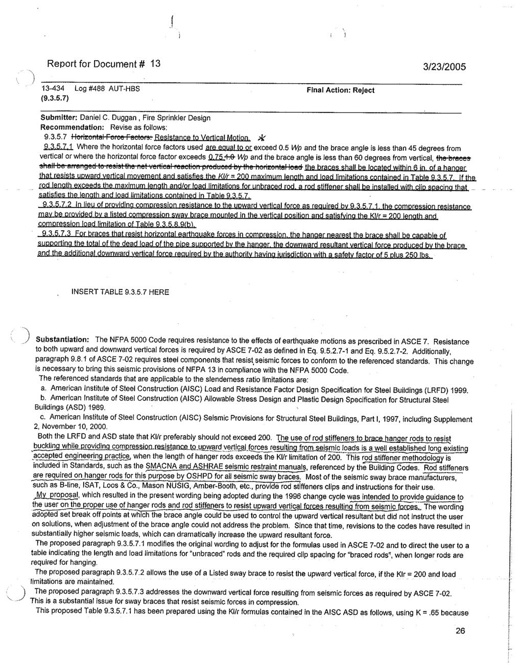
363 363
364 364
365 365
366 39 of 460 5/17/17, 8:45 AM Public Comment No. 132-NFPA [ Section No. A ] A Sprinkler protection under exterior projections should not be required to spray beyond the support beam on the exterior edge of the exterior projection as long as the maximum distance from the interior edge of support beam to the exterior edge of the projection does not exceed 4 ft.. An additional line of sprinklers on the exterior edge is not required due to obstruction rules. This is considered a reasonable level of protection since sprinklers are located between the structure and the exterior edge. See Figure A See Attached Figure Additional Proposed Changes File Name Description Approved ext_projection.pdf Figure A Statement of Problem and Substantiation for Public Comment This comment is in in support of FR-712 with the addition of a 4 ft maximum distance from the inside edge of the support beam to the outside edge of the exterior projection in order to omit sprinkler coverage beyond the support beam. If this distance exceeds 4 ft, the possibility of significant storage exists and sprinkler coverage should be mandated. To illustrate a figure is included. Related Item FR-712 Submitter Information Verification Submitter Full Name: Roland Asp Organization: National Fire Sprinkler Association Affilliation: NFSA Engineering and Standards Committee Street Address: City: State: Zip: Submittal Date: Tue May 09 09:11:30 EDT
367 367
368 40 of 460 5/17/17, 8:45 AM Public Comment No. 98-NFPA [ Section No. A ] A For protection of baled cotton, fire tests and actual fire experience indicate an initial low heat release; thus, sprinklers in the ordinary-temperature range should offer some advantage by opening faster than those of intermediate- or high-temperature classifications under similar conditions It is acceptable to install ordinary temperature sprinkler throughout a building, intermediate temperature sprinklers throughout a building or a mix of ordinary and intermediate temperature sprinkler throughout a building. Statement of Problem and Substantiation for Public Comment This comment is intended to clarify that it is acceptable to install intermediate temperature sprinklers in a building even when that sprinkler will not be exposed to ambient temperature in excess of 100F. Additionally it is acceptable to mix ordinary temperature sprinklers with intermediate temperature sprinklers. Although the allowance to allow intermediate temperature sprinklers throughout a building is not new, many AHJ's are only allowing intermediate temperature sprinklers where elevated temperatures are present. Also a separate comment seeks to move the existing A which deals with Baled cotton to section section A which is the baled cotton section Related Public Comments for This Document Related Comment Public Comment No. 99-NFPA [New Section after A ] Related Item PI-68 Relationship Submitter Information Verification Submitter Full Name: Roland Asp Organization: National Fire Sprinkler Association Affilliation: NFSA Engineering and Standards Committeee Street Address: City: State: Zip: Submittal Date: Mon May 08 15:37:57 EDT
369 41 of 460 5/17/17, 8:45 AM Public Comment No. 127-NFPA [ Section No. A ] A A diffuser in ceiling sheathing labeled by the manufacturer as horizontal discharge has directional vanes to move air further along the ceiling, and sprinklers located within the 2 ft 6 in. (750 mm) radius should have an intermediate-temperature rating. See Figure A (a) and Figure A (b). Figure A (a) Recessed Fireplace. [see two new drawings attached] Figure A (b) Open Fireplace. [ see two new drawings attached] Additional Proposed Changes File Name Description Approved FRONT_Fire_Place_ORDINARY.png Improved drawing to illustrate concept accepted in FR FRONT_Fire_Place_INTERMEDIATE.png Improved drawing to illustrate concept accepted in FR OPEN_Fire_Place_ORDINARY.png Improved drawing to illustrate concept accepted in FR 369
370 42 of 460 5/17/17, 8:45 AM OPEN_Fire_Place_INTERMEDIATE.png Improved drawing to illustrate concept accepted in FR Statement of Problem and Substantiation for Public Comment Improved drawings have been submitted to illustrate the concept accepted in the First Revision. This should be correlated across NFPA 13R and NFPA 13D. Related Item FR-905 Submitter Information Verification Submitter Full Name: Robert Upson Organization: National Fire Sprinkler Association Affilliation: NFSA Engineering and Standards Committee Street Address: City: State: Zip: Submittal Date: Tue May 09 08:12:56 EDT
371 371
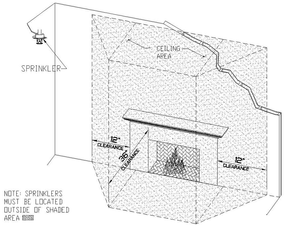
372 372
373 373
374 374
375 43 of 460 5/17/17, 8:45 AM Public Comment No. 173-NFPA [ Section No. A ] A See Figure A Figure A Maximum Distance from Walls. The above example is shown for a light hazard occupancy. However, the irregular shape room allowance also applies to ordinary and extra hazard occupancies Statement of Problem and Substantiation for Public Comment The purpose of FR 735 (based upon PI 415) was to indicate that this figure is applicable to all occupancy types even though the figure shows light hazard spacing. The following language (from PI 415) needs to be added: "The above example is shown for a light hazard occupancy. However, the irregular shape room allowance also applies to ordinary and extra hazard occupancies." Related Item FR-735 PI-415 Submitter Information Verification Submitter Full Name: Roland Asp Organization: National Fire Sprinkler Association Affilliation: NFSA Engineering and Standards Committee Street Address: City: State: Zip: Submittal Date: Tue May 09 14:57:16 EDT
376 44 of 460 5/17/17, 8:45 AM Public Comment No. 45-NFPA [ Section No. A ] A See Figure A Figure A Hip Roof Installations. Statement of Problem and Substantiation for Public Comment Add 6'-0" minimum or baffles required between the two sprinklers on opposing slopes. Related Item FR-679 Submitter Information Verification Submitter Full Name: Peter Schwab Organization: Wayne Automatic Fire Sprinkler Street Address: City: State: Zip: Submittal Date: Fri Apr 21 08:08:12 EDT
377 45 of 460 5/17/17, 8:45 AM Public Comment No. 316-NFPA [ New Section after A ] TITLE OF NEW CONTENT Type your content here... A Previously ESFR sprinklers could not be used in obstructed combustible construction. Fire testing has indicated that this restriction is no longer necessary. Statement of Problem and Substantiation for Public Comment This is a change to help explain the change in the standard. Related Public Comments for This Document Related Comment Public Comment No. 82-NFPA [Section No [Excluding any Sub-Sections]] Related Item Public Input No. 477-NFPA Relationship Change to help explain the change in the standard Submitter Information Verification Submitter Full Name: Thomas Noble Organization: AFSA Street Address: City: State: Zip: Submittal Date: Wed May 10 16:14:55 EDT
378 46 of 460 5/17/17, 8:45 AM Public Comment No. 284-NFPA [ Section No. A ] 378
379 47 of 460 5/17/17, 8:45 AM A
380 48 of 460 5/17/17, 8:45 AM Dry sprinklers must be of sufficient length to avoid freezing of the water-filled pipes due to conduction along the barrel. The values of exposed barrel length in Table (a) and Table (b) have been developed using an assumption of a properly sealed penetration and an assumed maximum wind velocity on the exposed sprinkler of 30 mph (48 km/h). Where higher wind velocity is expected, longer exposed barrel lengths will help avoid freezing of the wet piping. The total length of the barrel of the dry sprinkler must be longer than the values shown in Table (a) and Table (b) because the length shown in the tables is the minimum length of the barrel that needs to be exposed to the warmer ambient temperature in the heated space. See Figure A (a) for an example of where to measure the exposed barrel length for a sidewall sprinkler penetrating an exterior wall and Figure A (b) for an example of where to measure the exposed barrel length for a pendent sprinkler penetrating a ceiling or top of a freezer. There are times when it is acceptable to have the exposed barrel length to be measured within a wall cavity. If the wall cavity is a conditioned space and sufficient ambient temperatures are maintained in the wall cavity, the barrel within that cavity may be counted as the exposed barrel length. See figure A (e) for an example of exposedlength within a wall cavity. Figure A (a) Dry Sidewall Sprinkler Through Wall. Figure A (b) Dry Pendent Sprinkler Through Ceiling or Top of Freezer. Figure A (c) Dry Sidewall Sprinkler Through Wall 380
381 49 of 460 5/17/17, 8:45 AM Figure A (d) Dry Pendent Sprinkler Through Ceiling Additional Proposed Changes File Name Description Approved dry_sprinkler_in_wall_cavity.pdf Dry Sprinkler in wall cavity Statement of Problem and Substantiation for Public Comment There are times when it is acceptable to include the barrel length of a dry sprinkler that is located within a wall cavity as the exposed barrel length (X). As long as the wall cavity is considered as part of the "conditioned space" and sufficient temperatures are maintained within that wall cavity, there is no reason not to include this part of the dry sprinkler barrel as part of the exposed barrel length. This annex note is needed as section states that "the minimum exposed length shall be measured along the length of the dry sprinkler from the face of the fitting to the inside surface of the insulation, wall or ceiling to the cold space, whichever is closest to the the fitting.". The language "whichever is closest to the fitting" would not allow the area in the wall cavity to be counted even if this was a conditioned area with sufficient temperatures to meet the requirements of this section. Note if accepted this comment should be correlated with NFPA 13R and NFPA 13D (This comment has not been submitted to these documents as these section are not open) Related Item FR-725 Submitter Information Verification Submitter Full Name: Roland Asp Organization: National Fire Sprinkler Association Affilliation: NFSA Engineering and Standards Committee Street Address: 381
382 50 of 460 5/17/17, 8:45 AM City: State: Zip: Submittal Date: Wed May 10 13:45:20 EDT
383 383
384 51 of 460 5/17/17, 8:45 AM Public Comment No. 143-NFPA [ New Section after A ] A Such means should consist of a tee outlet downstream of the pressure reducing valve iden cal in size to the sprinkler system feed, available for connec on to field tes ng devices, or other method approved by the authority having jurisdic on. Statement of Problem and Substantiation for Public Comment This text provides one appropriate method to achieve the performance requirement of but arbitrarily excludes others. It should be relocated to the annex as a suggested but not required means of compliance. Related Public Comments for This Document Related Comment Public Comment No. 142-NFPA [Section No ] Related Item FR-659 Relationship Similar language deleted from body of standard Submitter Information Verification Submitter Full Name: Robert Upson Organization: National Fire Sprinkler Association Affilliation: NFSA Engineering and Standards Committee Street Address: City: State: Zip: Submittal Date: Tue May 09 11:00:18 EDT
385 52 of 460 5/17/17, 8:45 AM Public Comment No. 70-NFPA [ New Section after A ] Figure A (a) is an example of an unacceptable arrangement. Because it will not give a true residual reading, it will indicate an exessive pressure drop. Figure A (b) is an example of an acceptable drain connection for a system riser Provisions should include vents at the top of the drain risers in buildings more than six stories in height. An elbow near the top of the drain riser with a horizontal check valve facing in toward the system wolud be one acceptable arrangement. A check valve at the top of the drain riser would allow air into the drain riser and break any vacuum created by a standing column. Additional Proposed Changes File Name Description Approved Main_Drain_Connections.docx Main Drain Connections Statement of Problem and Substantiation for Public Comment During the rewrite / editing a number of Annex Section A and the corresponding Figure A (a) and Figure A (b) were deleted, with no substantiation or explanation. The text and the illustrations should be reinstated as Annex Section A , Figure A (a) and Figure A (b). The missing text and illustrations have stood the test of time and provide extremely valuable information / guidance. They should not be lost as part of the editing process. Additionally, Annex Section A was similarly omitted without substantiation and it too should be retained, as Annex Section A Related Item FR-644 Submitter Information Verification Submitter Full Name: Larry Keeping Organization: PLC Fire Safety Solutions Street Address: City: State: Zip: Submittal Date: Sun May 07 21:51:49 EDT
386 386
387 53 of 460 5/17/17, 8:45 AM Public Comment No. 73-NFPA [ New Section after A ] A See Figure A Additional Proposed Changes File Name Description Approved Water_Supply_With_Test_Connection.docx Water Supply With Test Connection Statement of Problem and Substantiation for Public Comment During the rewrite / editing Figure A was deleted, with no substantiation or explanation. The illustration should be reinstated as Annex Section A The missing figure has been part of NFPA 13 for a great many years (at least 45 to my knowledge). It has stood the test of time and provides extremely valuable information / guidance. It should not be lost as part of the editing process. Related Item FR-644 Submitter Information Verification Submitter Full Name: Larry Keeping Organization: PLC Fire Safety Solutions Street Address: City: State: Zip: Submittal Date: Sun May 07 23:20:14 EDT
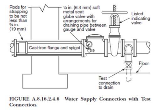
388 388
Dave Hague NFPA Staff Liaison 12 21,
 Technical Committee on Sprinkler System Installation First Draft Meeting Marriott Gas Lamp Hotel San Diego, CA August 9-11, 2016 1. Ray Grill TC Chair called the meeting to order at 8:00am and self-introductions
Technical Committee on Sprinkler System Installation Criteria
 Technical Committee on Sprinkler System Installation Criteria First Draft Meeting August 9-12, 2016 San Diego Marriott Gaslamp Quarter 660 K Street San Diego, CA 92101 AGENDA Tuesday August 9, 2016 1.
Technical Committee on Sprinkler System Installation Criteria
 Technical Committee on Sprinkler System Installation Criteria M E M O R A N D U M DATE: May 21, 2014 TO: FROM: Principal and Alternate Members of the Technical Committee on Sprinkler System Installation
Correlating Committee on Automatic Sprinklers
 Correlating Committee on Automatic Sprinklers First Draft Correlating Committee Meeting December 6, 2016 MEETING MINUTES 1. Call to Order. CC Chair Ken Linder called the meeting to order at 8AM. 2. Self-Introductions
Technical Committee on Sprinkler System Installation Criteria
 Technical Committee on Sprinkler System Installation Criteria M E M O R A N D U M DATE: January 17, 2010 TO: FROM: Principal and Alternate Members of the Technical Committee on Sprinkler System Installation
1. Welcome. Robert Smith, Chair. 2. Introductions and Update of Committee Roster. (attached)
") TECHNICAL COMMITTEE ON WATER-COOLING TOWERS NFPA 214 (F2015) Second Draft Meeting Agenda February 17, 2014 10:00 AM - 1:00 PM EST Web/Teleconference Meeting 1. Welcome. Robert Smith, Chair 2. Introductions
TECHNICAL COMMITTEE ON WATER-COOLING TOWERS NFPA 214 (F2015) Second Draft Meeting Agenda February 17, 2014 10:00 AM - 1:00 PM EST Web/Teleconference Meeting 1. Welcome. Robert Smith, Chair 2. Introductions
Public Comment No. 16-NFPA 13D-2014 [ Section No ]
![Public Comment No. 16-NFPA 13D-2014 [ Section No ]](/thumbs/90/103297636.jpg "Public Comment No. 16-NFPA 13D-2014 [ Section No ]") of 52 9/22/2014 9:20 AM Public Comment No. 16-NFPA 13D-2014 [ Section No. 2.3.3 ] 2.3.3 ASTM Publications. ASTM International, 100 Barr Harbor Drive, P.O. Box C700, West Conshohocken, PA 19428-2959. ASTM
of 52 9/22/2014 9:20 AM Public Comment No. 16-NFPA 13D-2014 [ Section No. 2.3.3 ] 2.3.3 ASTM Publications. ASTM International, 100 Barr Harbor Drive, P.O. Box C700, West Conshohocken, PA 19428-2959. ASTM
Correlating Committee on Automatic Sprinkler Systems
 Correlating Committee on Automatic Sprinkler Systems M E M O R A N D U M DATE: June 19, 2013 TO: FROM: and Alternate Members of the Correlating Committee on Automatic Sprinkler Systems Matt Klaus, Fire
Public Comment No. 20-NFPA [ Section No ] Statement of Problem and Substantiation for Public Comment Related Item
![Public Comment No. 20-NFPA [ Section No ] Statement of Problem and Substantiation for Public Comment Related Item](/thumbs/75/72069029.jpg "Public Comment No. 20-NFPA [ Section No ] Statement of Problem and Substantiation for Public Comment Related Item") of 27 9/2/2014 9:27 AM Public Comment No. 20-NFPA 24-2014 [ Section No. 2.3.2 ] 2.3.2 ASTM Publications. ASTM International, 100 Barr Harbor Drive, P.O. Box C700, West Conshohocken, PA 19428-2959. ASTM
of 27 9/2/2014 9:27 AM Public Comment No. 20-NFPA 24-2014 [ Section No. 2.3.2 ] 2.3.2 ASTM Publications. ASTM International, 100 Barr Harbor Drive, P.O. Box C700, West Conshohocken, PA 19428-2959. ASTM
Correlating Committee on Automatic Sprinkler Systems
 Correlating Committee on Automatic Sprinkler Systems First Draft Meeting December 6-7, 2016 Buena Vista Palace 1900 E. Buena Vista Drive Lake Buena Vista, FL 32830 AGENDA day, December 6, 2016 1. Call
Resolution: FR-2-NFPA Statement: The new language requires the action completed by NFPA 557 be prepared by a person that is approved.
 Public Input No. 1-NFPA 557-2012 [ New Section after 1.5.3 ] 1.6 Approved Qualifications The design shall be prepared by a person with qualifications acceptable to the AHJ. The term designer is used in
(a) Flame shall not spread to the outer extremities of the sample on the 8 ft 12 ft (2440 mm 3660 mm) wall. Flashover shall not occur.
 Flame shall not spread to the outer extremities of the sample on the 8 ft 12 ft (2440 mm 3660 mm) wall. Flashover shall not occur.") First Revision No. 1-NFPA 501-2015 [ Section No. 5.3.1.3 ] 5.3.1.3 The following conditions shall be met when an interior finish material is tested using the test protocol of NFPA 286, Standard Methods
First Revision No. 1-NFPA 501-2015 [ Section No. 5.3.1.3 ] 5.3.1.3 The following conditions shall be met when an interior finish material is tested using the test protocol of NFPA 286, Standard Methods
TECHNICAL COMMITTEE ON MANUFACTURE OF ORGANIC COATINGS First Draft Meeting Agenda March 19, :00 AM - 5:00 PM EST Web/Teleconference Meeting
 TECHNICAL COMMITTEE ON MANUFACTURE OF ORGANIC COATINGS First Draft Meeting Agenda March 19, 2014 9:00 AM - 5:00 PM EST Web/Teleconference Meeting 1. Welcome. George Seuss, Chair 2. Introductions and Update
FINAL REPORT* OF THE MOTIONS COMMITTEE 2015 ASSOCIATION TECHNICAL MEETING JUNE 22-25, 2015 CHICAGO, IL
 FINAL REPORT* OF THE MOTIONS COMMITTEE 2015 ASSOCIATION TECHNICAL MEETING JUNE 22-25, 2015 CHICAGO, IL I. Introduction This is the second and Final Report* of the s Committee listing Certified Amending
Technical Committee on Hanging and Bracing of Water-Based Fire Protection Systems
 Technical Committee on Hanging and Bracing of Water-Based Fire Protection Systems M E M O R A N D U M DATE: May 26, 2016 TO: Members of the Technical Committee on Hanging and Bracing of Water-Based Fire
1 of /3/ :03 PM. Public Input No. 1-NFPA 13D-2015 [ Chapter 2 ]
![1 of /3/ :03 PM. Public Input No. 1-NFPA 13D-2015 [ Chapter 2 ]](/thumbs/95/123561097.jpg "1 of /3/ :03 PM. Public Input No. 1-NFPA 13D-2015 [ Chapter 2 ]") 1 of 129 11/3/2016 12:03 PM Public Input No. 1-NFPA 13D-2015 [ Chapter 2 ] 2 of 129 11/3/2016 12:03 PM American Society of Mechanical Engineers Chapter 2 Referenced Publications 2.1 General. The documents
1 of 129 11/3/2016 12:03 PM Public Input No. 1-NFPA 13D-2015 [ Chapter 2 ] 2 of 129 11/3/2016 12:03 PM American Society of Mechanical Engineers Chapter 2 Referenced Publications 2.1 General. The documents
TECHNICAL COMMITTEE ON WATER-COOLING TOWERS. First Draft Meeting Agenda. February 7, :00 AM - 5:00 PM EST Web/Teleconference Meeting
 TECHNICAL COMMITTEE ON WATER-COOLING TOWERS First Draft Meeting Agenda February 7, 2014 10:00 AM - 5:00 PM EST Web/Teleconference Meeting 1. Welcome. Robert Smith, Chair 2. Introductions and Update of
NFPA Technical Committee on Hybrid (Water and Inert Gas) Fire Extinguishing Systems
 Fire Extinguishing Systems") San Antonio, TX October 12-14, 2016 The following are the meeting minutes from the third meeting of the Technical Committee on Hybrid (Water and Inert Gas) Fire Extinguishing Systems held in San Antonio,
San Antonio, TX October 12-14, 2016 The following are the meeting minutes from the third meeting of the Technical Committee on Hybrid (Water and Inert Gas) Fire Extinguishing Systems held in San Antonio,
Technical Correlating Committee on Automatic Sprinklers
 Technical Correlating Committee on Automatic Sprinklers ROC Meeting December 6, 2011 Windows Live Meeting and Conference Call AGENDA 1. Call to Order (1:00 PM) (Acting TCC Chair Ken Linder). 2. Self-Introductions
Public Input No. 1-NFPA 99B-2015 [ Section No. 2.3 ] Statement of Problem and Substantiation for Public Input. Related Public Inputs for This Document
![Public Input No. 1-NFPA 99B-2015 [ Section No. 2.3 ] Statement of Problem and Substantiation for Public Input. Related Public Inputs for This Document](/thumbs/72/66518590.jpg "Public Input No. 1-NFPA 99B-2015 [ Section No. 2.3 ] Statement of Problem and Substantiation for Public Input. Related Public Inputs for This Document") 1 of 19 10/21/2015 1:20 PM Public Input No. 1-NFPA 99B-2015 [ Section No. 2.3 ] 2.3 Other Publications. 2.3.1 ASME Publications. American Society of Mechanical Engineers, Three ASME International, Two
1 of 19 10/21/2015 1:20 PM Public Input No. 1-NFPA 99B-2015 [ Section No. 2.3 ] 2.3 Other Publications. 2.3.1 ASME Publications. American Society of Mechanical Engineers, Three ASME International, Two
Technical Committee on Water Spray Fixed Systems (WAS-AAA)
") Technical Committee on Water Spray Fixed Systems () M E M O R A N D U M DATE: August 21, 2015 TO: FROM: and Members of the Technical Committee on Water Spray Fixed Systems () Chad Duffy, NFPA Staff Liaison
Technical Committee on Water Spray Fixed Systems () M E M O R A N D U M DATE: August 21, 2015 TO: FROM: and Members of the Technical Committee on Water Spray Fixed Systems () Chad Duffy, NFPA Staff Liaison
NFPA Technical Committee on Building Systems. NFPA 900 First Draft Teleconference/Web Meeting AGENDA. Thursday, February 13, :00 a.m.
 1. Call to Order: NFPA Technical Committee on Building Systems NFPA 900 First Draft Teleconference/Web Meeting AGENDA Thursday, February 13, 2014 11:00 a.m. Noon EDT Online meeting link: http://nfpa.adobeconnect.com/r366m2eaxx6/
Correlating Committee on Automatic Sprinkler Systems
 Correlating Committee on Automatic Sprinkler Systems M E M O R A N D U M DATE: May 14, 2014 TO: FROM: Principal and Alternate Members of the Correlating Committee on Automatic Sprinkler Systems Matt Klaus,
Public Comment No. 2-NFPA [ Section No ]
![Public Comment No. 2-NFPA [ Section No ]](/thumbs/89/98636858.jpg "Public Comment No. 2-NFPA [ Section No ]") Public Comment No. 2-NFPA 16-2013 [ Section No. 3.3.6 ] 3.3.6* Foam-Water Sprinkler System. A piping network connected to a source of foam concentrate and to a water supply. The piping network is equipped
Public Comment No. 2-NFPA 16-2013 [ Section No. 3.3.6 ] 3.3.6* Foam-Water Sprinkler System. A piping network connected to a source of foam concentrate and to a water supply. The piping network is equipped
M E M O R A N D U M. According to the final ballot results, all ballot items received the necessary affirmative votes to pass ballot.
 National Fire Protection Association 1 Batterymarch Park, Quincy, MA 02169-7471 Phone: 617-770-3000 Fax: 617-770-0700 www.nfpa.org M E M O R A N D U M To: From: NFPA Technical Committee on Helicopter Facilities
Technical Committee on Private Water Supplies
 Technical Committee on Private Water Supplies First Draft Meeting July 11, 2016 San Diego Marriott Mission Valley 8757 Rio San Diego Drive San Diego, CA 92108 AGENDA Monday July 11, 2016 1. Call to Order
National Fire Protection Association. 1 Batterymarch Park, Quincy, MA Phone: Fax:
 National Fire Protection Association 1 Batterymarch Park, Quincy, MA 02169-7471 Phone: 617-770-3000 Fax: 617-770-0700 www.nfpa.org M E M O R A N D U M TO: FROM: NFPA Technical Committee on Sprinkler System
Revise the metric values throughout the standard to follow the soft conversions provided by the metric task group
 of 36 9/22/2014 9:37 AM Second Revision No. 14-NFPA 13D-2014 [ Global Comment ] Revise the metric values throughout the standard to follow the soft conversions provided by the metric task group Supplemental
Public Input No. 1-NFPA 90B-2015 [ Chapter 2 ]
![Public Input No. 1-NFPA 90B-2015 [ Chapter 2 ]](/thumbs/74/71051808.jpg "Public Input No. 1-NFPA 90B-2015 [ Chapter 2 ]") Public Input No. 1-NFPA 90B-2015 [ Chapter 2 ] Chapter 2 Referenced Publications 2.1 General. The documents or portions thereof listed in this chapter are referenced within this standard and shall be considered
Public Input No. 1-NFPA 90B-2015 [ Chapter 2 ] Chapter 2 Referenced Publications 2.1 General. The documents or portions thereof listed in this chapter are referenced within this standard and shall be considered
National Fire Protection Association. 1 Batterymarch Park, Quincy, MA Phone: Fax:
 National Fire Protection Association 1 Batterymarch Park, Quincy, MA 02169-7471 Phone: 617-770-3000 Fax: 617-770-0700 www.nfpa.org M E M O R A N D U M TO: FROM: NFPA Technical Committee on Merchant Vessels
National Fire Protection Association. 1 Batterymarch Park, Quincy, MA Phone: Fax:
 National Fire Protection Association 1 Batterymarch Park, Quincy, MA 02169-7471 Phone: 617-770-3000 Fax: 617-770-0700 www.nfpa.org M E M O R A N D U M TO: FROM: Technical Committee on Residential Sprinkler
National Fire Protection Association. 1 Batterymarch Park, Quincy, MA Phone: Fax:
 National Fire Protection Association 1 Batterymarch Park, Quincy, MA 02169-7471 Phone: 617-770-3000 Fax: 617-770-0700 www.nfpa.org M E M O R A N D U M TO: FROM: NFPA Technical Committee on Sprinkler System
Second Revision No. 3-NFPA [ Section No. 2.3 ]
![Second Revision No. 3-NFPA [ Section No. 2.3 ]](/thumbs/96/127511130.jpg "Second Revision No. 3-NFPA [ Section No. 2.3 ]") Second Revision No. 3-NFPA 804-2014 [ Section No. 2.3 ] 2.3 Other Publications. 2.3.1 ASME Publications. American Society of Mechanical Engineers, Three Park Avenue, New York, NY 10016-5990. ASME Boiler
Second Revision No. 3-NFPA 804-2014 [ Section No. 2.3 ] 2.3 Other Publications. 2.3.1 ASME Publications. American Society of Mechanical Engineers, Three Park Avenue, New York, NY 10016-5990. ASME Boiler
NFPA Technical Meeting (Tech Session) June 24-25, 2015 Agenda*
 June 24-25, 2015 Agenda*") NFPA Technical Meeting (Tech Session) June 24-25, 2015 Agenda* NFPA Standards presented for Action Wednesday, June 24, 2015 starting @ 2:00pm: NFPA 33, Standard for Spray Application Using Flammable or
NFPA Technical Meeting (Tech Session) June 24-25, 2015 Agenda* NFPA Standards presented for Action Wednesday, June 24, 2015 starting @ 2:00pm: NFPA 33, Standard for Spray Application Using Flammable or
TECHNICAL COMMITTEE ON SAFETY AT MOTORSPORTS VENUES. NFPA 610 First Draft Meeting. October 17-18, 2016
 TECHNICAL COMMITTEE ON SAFETY AT MOTORSPORTS VENUES NFPA 610 First Draft Meeting October 17-18, 2016 Westin Kansas City at Crown Center 1 East Pershing Road Kansas City, MO, 64108 Conference Call Access:
Technical Committee on Fluidized Bed Boilers
 Technical on Fluidized Bed Boilers AGENDA Web/Teleconference 1. Chair s welcome, call to order, and opening remarks at 1:00 pm EST. 2. Self-Introduction of Members and Guests 3. Approval of Minutes from
2016 Annual Revision Cycle Consent Document NFPA 75
 2016 Annual Revision Cycle Consent Document NFPA 75 The Committee on Electronic Computer Systems produced a Technical Committee Report that received at least one Notice of Intent to Make a Motion (NITMAM)
REPORT OF THE NFPA MOTIONS COMMITTEE* ON FALL 2013 REVISION CYCLE STANDARDS
 REPORT OF THE NFPA MOTIONS COMMITTEE* ON FALL 2013 REVISION CYCLE STANDARDS I. Introduction. This is the Motions Committee Report on Standards in the Fall 2013 Revision Cycle. The report identifies Certified
First Revision No. 2-NFPA [ Global Input ] Submitter Information Verification. Committee Statement. 1 of 11 1/18/2016 5:43 PM
![First Revision No. 2-NFPA [ Global Input ] Submitter Information Verification. Committee Statement. 1 of 11 1/18/2016 5:43 PM](/thumbs/95/122743458.jpg "First Revision No. 2-NFPA [ Global Input ] Submitter Information Verification. Committee Statement. 1 of 11 1/18/2016 5:43 PM") 1 of 11 1/18/2016 5:43 PM First Revision No. 2-NFPA 51-2015 [ Global Input ] Throughout standard remove references to the following and replace with the following: (1) CGA C-7 Guide to Precautionary Labelling
1 of 11 1/18/2016 5:43 PM First Revision No. 2-NFPA 51-2015 [ Global Input ] Throughout standard remove references to the following and replace with the following: (1) CGA C-7 Guide to Precautionary Labelling
Public Comment No. 23-NFPA [ Section No ] Statement of Problem and Substantiation for Public Comment Related Item
![Public Comment No. 23-NFPA [ Section No ] Statement of Problem and Substantiation for Public Comment Related Item](/thumbs/88/116226748.jpg "Public Comment No. 23-NFPA [ Section No ] Statement of Problem and Substantiation for Public Comment Related Item") Public Comment No. 23-NFPA 96-2015 [ Section No. 2.3.1 ] 2.3.1 ASTM Publications. ASTM International, 100 Barr Harbor Drive, P.O. Box C700, West Conshohocken, PA 19428-2959. ASTM E84, Standard Test Method
Public Comment No. 23-NFPA 96-2015 [ Section No. 2.3.1 ] 2.3.1 ASTM Publications. ASTM International, 100 Barr Harbor Drive, P.O. Box C700, West Conshohocken, PA 19428-2959. ASTM E84, Standard Test Method
National Fire Protection Association. 1 Batterymarch Park, Quincy, MA Phone: Fax:
 National Fire Protection Association 1 Batterymarch Park, Quincy, MA 02169-7471 Phone: 617-770-3000 Fax: 617-770-0700 www.nfpa.org M E M O R A N D U M TO: FROM: NFPA Technical Correlating Committee on
Second Revision No. 1-NFPA 90A-2016 [ Section No ] Submitter Information Verification. Committee Statement
![Second Revision No. 1-NFPA 90A-2016 [ Section No ] Submitter Information Verification. Committee Statement](/thumbs/89/99621071.jpg "Second Revision No. 1-NFPA 90A-2016 [ Section No ] Submitter Information Verification. Committee Statement") Second Revision No. 1-NFPA 90A-2016 [ Section No. 2.3.2 ] 2.3.2 ASTM International Publications. ASTM International, 100 Barr Harbor Drive, P.O. Box C700, West Conshohocken, PA 19428-2959. ASTM C411, Standard
Second Revision No. 1-NFPA 90A-2016 [ Section No. 2.3.2 ] 2.3.2 ASTM International Publications. ASTM International, 100 Barr Harbor Drive, P.O. Box C700, West Conshohocken, PA 19428-2959. ASTM C411, Standard
Technical Committee on Water Mist Fire Suppression Systems
 Date: January 29, 2013 1. Call to Order. Meeting was called to order by Chair Larry Owen at 8:00 AM. 2. Building Safety Message. Building safety was discussed and exits identified by Chair Larry Owen.
National Fire Protection Association. 1 Batterymarch Park, Quincy, MA Phone: Fax:
 National Fire Protection Association 1 Batterymarch Park, Quincy, MA 02169-7471 Phone: 617-770-3000 Fax: 617-770-0700 www.nfpa.org M E M O R A N D U M TO: FROM: NFPA Technical Committee on Cultural Resources
NFPA Technical Committee on Fire Tests FALL 2011 ROC MEETING MINUTES
 National Fire Protection Association 1 Batterymarch Park, Quincy, MA 02169-7471 Phone: 617-770-3000 Fax: 617-770-0700 www.nfpa.org NFPA Technical Committee on Fire Tests FALL 2011 ROC MEETING MINUTES 1.
NFPA Technical Committee on Fire Tests FALL 2010 ROC MEETING MINUTES April 15-16, 2010 Southwest Research Institute San Antonio, TX
 NFPA Technical Committee on Fire Tests FALL 2010 ROC MEETING MINUTES April 15-16, 2010 Southwest Research Institute San Antonio, TX 1. Call to Order. The meeting of the Technical Committee on Fire Tests
Technical Committee on Residential Sprinkler Systems
 Technical Committee on Residential Sprinkler Systems M E M O R A N D U M DATE: June 10, 2016 TO: Members of the Technical Committee on Residential Sprinkler Systems FROM: David R. Hague, Fire Protection
MEMORANDUM. NFPA 51 First Draft Technical Committee FINAL Ballot Results (A2017 Cycle)
") National Fire Protection Association 1 Batterymarch Park, Quincy, MA 02169-7471 Phone: 617-770-3000 Fax: 617-770-0700 www.nfpa.org MEMORANDUM TO: FROM: Technical Committee on Industrial and Medical Gases
National Fire Protection Association 1 Batterymarch Park, Quincy, MA 02169-7471 Phone: 617-770-3000 Fax: 617-770-0700 www.nfpa.org MEMORANDUM TO: FROM: Technical Committee on Industrial and Medical Gases
M E M O R A N D U M. NFPA Technical Committee on Water Spray Fixed Systems
 National Fire Protection Association 1 Batterymarch Park, Quincy, MA 02169-7471 Phone: 617-770-3000 Fax: 617-770-0700 www.nfpa.org M E M O R A N D U M To: From: NFPA Technical Committee on Water Spray
NFPA 550 ROP Meeting Minutes
 NFPA 550 ROP Meeting Minutes NFPA Technical Committee on Fire Risk Assessment Methods (FIR-AAA) June 24, 2010 Microsoft Live Meeting 1. Call to order. The meeting was called to order at 1:00 PM on Monday,
Technical Committee on Residential Sprinklers
 Technical Committee on Residential Sprinklers 1. Call to Order 8:00 AM 2. Introductions of Members and Staff First Draft Meeting July 13 & 14, 2016 San Diego Marriott Mission Valley 8757 Rio San Diego
First Revision No. 2-NFPA 90B-2012 [ Section No. 1.3 ] Submitter Information Verification. Committee Statement and Meeting Notes
![First Revision No. 2-NFPA 90B-2012 [ Section No. 1.3 ] Submitter Information Verification. Committee Statement and Meeting Notes](/thumbs/78/77992447.jpg "First Revision No. 2-NFPA 90B-2012 [ Section No. 1.3 ] Submitter Information Verification. Committee Statement and Meeting Notes") First Revision No. 2-NFPA 90B-2012 [ Section No. 1.3 ] 1.3 Application. 1.3.1 This standard shall apply to all systems for the movement of environmental air in structures that serve the following, except
First Revision No. 2-NFPA 90B-2012 [ Section No. 1.3 ] 1.3 Application. 1.3.1 This standard shall apply to all systems for the movement of environmental air in structures that serve the following, except
Throughout standard remove references to the following and replace with the following:
 of 35 12/3/2015 7:13 AM Public Input No. 1-NFPA 90A-2015 [ Global Input ] Throughout standard remove references to the following and replace with the following: (1) ANSI/UL and replace with UL. (2) ANSI/ASHRAE
FIF AAA (F2014) Second Draft Meeting Web/Teleconference Meeting Agenda March 18, :00 5:00 p.m. ET
 Second Draft Meeting Web/Teleconference Meeting Agenda March 18, :00 5:00 p.m. ET") NFPA 804, Standard for Fire Protection for Advanced Light Water Reactor Electric Generating Plants, NFPA 805, Performance Based Standard for Fire Protection for Light Water Reactor Electric Generating
NFPA 804, Standard for Fire Protection for Advanced Light Water Reactor Electric Generating Plants, NFPA 805, Performance Based Standard for Fire Protection for Light Water Reactor Electric Generating
"Spray area" is the term that is used throughout the document. This change is for consistency.
 of 78 5/30/2014 2:08 PM Public Comment No. 39-NFPA 33-2013 [ Global Input ] For Chapter 18, replace "spray paint area" with "spray area". "Spray area" is the term that is used throughout the document.
Technical Committee on Foam-Water Sprinklers
 Technical Committee on Foam-Water Sprinklers M E M O R A N D U M DATE: February 27, 2017 TO: FROM: and Alternate Members of the Technical Committee on Foam-Water Sprinklers Dave Hague, Fire Protection
The distances in shall be reduced to 130 ft (39.7 m) when manual dry standpipes are installed in open parking garages.
 when manual dry standpipes are installed in open parking garages.") of 123 6/10/2014 9:07 AM First Revision No. 117-NFPA 14-2014 [ Global Input ] 7.3.2.7.5 The distances in 7.3.2.2 shall be reduced to 130 ft (39.7 m) when manual dry standpipes are installed in open parking
of 123 6/10/2014 9:07 AM First Revision No. 117-NFPA 14-2014 [ Global Input ] 7.3.2.7.5 The distances in 7.3.2.2 shall be reduced to 130 ft (39.7 m) when manual dry standpipes are installed in open parking
Agenda Technical Committee on Initiating Devices for Fire Alarm and Signaling Systems June 24-25, 2013 Saint Louis, MO
 Agenda Technical Committee on Initiating Devices for Fire Alarm and Signaling Systems June 24-25, 2013 Saint Louis, MO Item No. Subject 13-6-1 Call to Order (8:00 A.M) 13-6-2 Roll Call 13-6-3 Approval
First Revision No. 6-NFPA 90A-2012 [ Chapter NFPA ] Submitter Information Verification. Committee Statement and Meeting Notes
![First Revision No. 6-NFPA 90A-2012 [ Chapter NFPA ] Submitter Information Verification. Committee Statement and Meeting Notes](/thumbs/74/70429273.jpg "First Revision No. 6-NFPA 90A-2012 [ Chapter NFPA ] Submitter Information Verification. Committee Statement and Meeting Notes") First Revision No. 6-NFPA 90A-2012 [ Chapter NFPA ] 4.3.11.5.5 Materials within a raised floor plenum exposed to the airflow shall be (a) noncombustible or (b) exhibit a maximum flame spread index of 25
First Revision No. 6-NFPA 90A-2012 [ Chapter NFPA ] 4.3.11.5.5 Materials within a raised floor plenum exposed to the airflow shall be (a) noncombustible or (b) exhibit a maximum flame spread index of 25
NFPA 25 Technical Committee for Inspection, Testing and Maintenance of Water-Based Fire Protection Systems
 NFPA 25 Technical Committee for Inspection, Testing and Maintenance of Water-Based Fire Protection Systems M E M O R A N D U M DATE: September 1, 2015 TO: FROM: Principal and Alternate Members of the Technical
12/21/2015 National Fire Protection Association Report
 http://submittals.nfpa.org/terraviewweb/viewerpage.jsp?id=232 2012.ditamap&toc=false&draft=true 1/9 Public Comment No. 1 NFPA 232 2015 [ Chapter 2 ] Chapter 2 Referenced Publications 2.1 General. The documents
Remove the "Exception" text to be consistent with direction provided in the MOS.
 of 37 1/11/2017 7:38 AM Public Input No. 9-NFPA 88A-2015 [ Global Input ] Remove the "Exception" text to be consistent with direction provided in the MOS. The current language in 88A has numerous section
DIVISION 21: FIRE SUPPRESSION SYSTEMS SECTION Fire Protection Systems Protecting Cold Storage and Unheated Warehouses
 PART 1 - GENERAL 1.1 SCOPE A. Through Class III Commodity Classification, up to 12.2m of single, double or multiple row rack storage, up to 14.6m building height (VanQuish Fire Sprinkler System). Cartoned
WORKING DRAFT OF COMMITTEE MEETING OUTPUT
 WORKING DRAFT OF COMMITTEE MEETING OUTPUT CONTENT NOT FINAL SUBJECT TO REVISION PRIOR TO LETTER BALLOT AND PUBLICATION OF SECOND DRAFT REPORT Document: NFPA 221 Revision Cycle: A2014 Meeting Date: 5/20/2013
MEETING AGENDA High Rise Building Safety Advisory Committee
 MEETING AGENDA High Rise Building Safety Advisory Committee Renaissance Blackstone Chicago 636 South Michigan Avenue, Chicago, IL 60605 May 13-14, 2014 Chicago, IL 1. Call to Order. Call the meeting to
NFPA Edition Update
 NFPA 13 2013 Edition Update Session Agenda A2012 Code Cycle NFPA 13 Code Development Changes to NFPA 13 (NFPA 24) What Didn t Happen Next Steps 2 A2012 Code Cycle 800+ Proposal 500+ Comments TCC Meeting
National Fire Protection Association. 1 Batterymarch Park, Quincy, MA Phone: Fax:
 National Fire Protection Association 1 Batterymarch Park, Quincy, MA 02169-7471 Phone: 617-770-3000 Fax: 617-770-0700 www.nfpa.org M E M O R A N D U M TO: FROM: NFPA Technical Committee on Mercantile and
2015 Fall Revision Cycle Notice of a Consent Standard NFPA 102
 2015 Fall Revision Cycle Notice of a Consent Standard NFPA 102 The Committee on Assembly Occupancies produced a First Revision Report for NFPA 102, Standard for Grandstands, Folding and Telescopic Seating,
MEMORANDUM. Technical Committee on Emergency Power Supplies. NFPA 111 First Draft Technical Committee FINAL Ballot Results (A2018)
") National Fire Protection Association 1 Batterymarch Park, Quincy, MA 02169-7471 Phone: 617-770-3000 Fax: 617-770-0700 www.nfpa.org MEMORANDUM TO: FROM: Technical Committee on Emergency Power Supplies Kelly
National Fire Protection Association 1 Batterymarch Park, Quincy, MA 02169-7471 Phone: 617-770-3000 Fax: 617-770-0700 www.nfpa.org MEMORANDUM TO: FROM: Technical Committee on Emergency Power Supplies Kelly
Location of Requirements Listed Category I appliances Type B gas vent 12.7 Listed appliances equipped with. Chimney Single wall metal pipe 12.
 2/18/2016 National Fire Protection Association Report Committee Input No. 70 NFPA 54 2015 [ Section No. 12.5 ] This was a First Revision that failed ballot. 12.5 Type of Venting System to Be Used. 12.5.1
Reference to the Smoke Damage Index (SDI) is needed as it is part of the test method.
 is needed as it is part of the test method.") Public Input No. 4-NFPA 287-2014 [ Section No. 1.2.3.2 ] 1.2.3.2 Indices resulting from the test methods include critical heat flux (CHF), thermal response parameter (TRP), fire propagation index (FPI),
Public Input No. 4-NFPA 287-2014 [ Section No. 1.2.3.2 ] 1.2.3.2 Indices resulting from the test methods include critical heat flux (CHF), thermal response parameter (TRP), fire propagation index (FPI),
Page 1 of 6 10/19/2016 9:49 AM. Public Input No. 4-NFPA [ Section No ] Statement of Problem and Substantiation for Public Input
![Page 1 of 6 10/19/2016 9:49 AM. Public Input No. 4-NFPA [ Section No ] Statement of Problem and Substantiation for Public Input](/thumbs/84/89680532.jpg "Page 1 of 6 10/19/2016 9:49 AM. Public Input No. 4-NFPA [ Section No ] Statement of Problem and Substantiation for Public Input") Public Input No. 4-NFPA 111-2016 [ Section No. 1.1.4.1 ] 1.1.4.1 * This standard shall not cover the following: (1) Application of the SEPSS (2) Distribution wiring (3) Systems having total outputs less
Public Input No. 4-NFPA 111-2016 [ Section No. 1.1.4.1 ] 1.1.4.1 * This standard shall not cover the following: (1) Application of the SEPSS (2) Distribution wiring (3) Systems having total outputs less
Public Comment No. 2-NFPA [ Section No ] Statement of Problem and Substantiation for Public Comment. Submitter Information Verification
![Public Comment No. 2-NFPA [ Section No ] Statement of Problem and Substantiation for Public Comment. Submitter Information Verification](/thumbs/94/119830052.jpg "Public Comment No. 2-NFPA [ Section No ] Statement of Problem and Substantiation for Public Comment. Submitter Information Verification") Public Comment No. 2-NFPA 73-2014 [ Section No. 4.1.3 ] 4.1.3 Unused Openings. 4.1.3.1 Unused openings, other than those intended for the operation of equipment, those intended for mounting purposes, or
Public Comment No. 2-NFPA 73-2014 [ Section No. 4.1.3 ] 4.1.3 Unused Openings. 4.1.3.1 Unused openings, other than those intended for the operation of equipment, those intended for mounting purposes, or
Public Input No. 3-NFPA [ Chapter 2 ]
![Public Input No. 3-NFPA [ Chapter 2 ]](/thumbs/79/79559885.jpg "Public Input No. 3-NFPA [ Chapter 2 ]") Public Input No. 3-NFPA 655-2014 [ Chapter 2 ] Chapter 2 Referenced Publications 2.1 General. The documents or portions thereof listed in this chapter are referenced within this standard and shall be considered
Public Input No. 3-NFPA 655-2014 [ Chapter 2 ] Chapter 2 Referenced Publications 2.1 General. The documents or portions thereof listed in this chapter are referenced within this standard and shall be considered
First Revision No. 1-NFPA [ Chapter 2 ]
![First Revision No. 1-NFPA [ Chapter 2 ]](/thumbs/71/65939713.jpg "First Revision No. 1-NFPA [ Chapter 2 ]") First Revision No. 1-NFPA 499-2014 [ Chapter 2 ] Chapter 2 Referenced Publications 2.1 General. The documents or portions thereof listed in this chapter are referenced within this recommended practice
First Revision No. 1-NFPA 499-2014 [ Chapter 2 ] Chapter 2 Referenced Publications 2.1 General. The documents or portions thereof listed in this chapter are referenced within this recommended practice
Obstructions and ESFR Sprinklers Phase 2 FINAL REPORT
 Obstructions and ESFR Sprinklers Phase 2 FINAL REPORT PREPARED BY: Garner A. Palenske, P.E., and William N. Fletcher, P.E. Aon Fire Protection Engineering San Diego, CA, USA September 2015 Fire Protection
NFPA 1091 FIRST DRAFT MEETING
 Technical Committee on Traffic Control Incident Management NFPA 1091 FIRST DRAFT MEETING Orlando, FL February 16, 2017 AGENDA 1. Call to order at 8:00am 2. Introductions 3. Opening remarks Chair 4. Review
Standard Procedure s for Tenant Fire Sprinkler Work
 Standard Procedure s for Tenant Fire Sprinkler Work 1. Provide tenant a copy of Simon Property Group Standards for Fire Protection Systems, Section 15400, requesting they in turn would give the standards
FINAL* REPORT OF THE MOTIONS COMMITTEE
 FINAL* REPORT OF THE MOTIONS COMMITTEE ON CERTIFIED AMENDING MOTIONS FOR PRESENTATION AT THE 2012 ASSOCIATION TECHNICAL MEETING JUNE 13-14, 2012 LAS VEGAS, NEVADA I. Introduction. This is the second and
MEMORANDUM. Technical Committee on Board and Care Facilities. NFPA 101 Second Draft Technical Committee FINAL Ballot Results (A2017)
") National Fire Protection Association 1 Batterymarch Park, Quincy, MA 02169-7471 Phone: 617-770-3000 Fax: 617-770-0700 www.nfpa.org MEMORANDUM TO: FROM: Technical Committee on Board and Care Facilities
National Fire Protection Association 1 Batterymarch Park, Quincy, MA 02169-7471 Phone: 617-770-3000 Fax: 617-770-0700 www.nfpa.org MEMORANDUM TO: FROM: Technical Committee on Board and Care Facilities
 Page 1 of 19 Committee Input No. 14-NFPA 33-2013 [ Global Input ] Type your content here... Supplemental Information File Name IndoorDraftforCI.docx Description This committee input would be added to new
Technical Committee on Mining Facilities First Draft Meeting - NFPA 120 and 122
 Technical Committee on Mining Facilities First Draft Meeting - NFPA 120 and 122 Zurich Hosted 1400 America Lane Schaumburg, Illinois May 22 23, 2013 AGENDA 1. Chair Matt Bujewski calls meeting to order
Fire Prevention Coffee Break Training. May 2017
 Fire Prevention Coffee Break Training May 2017 Agenda Introduction Submittals - Phelan Changes to NFPA 13 - Phelan Questions and Answers Open Forum Please welcome our S ummer Intern Charlie Poppe Small
Change all instances of "flame resistant (hypobaric)" to "Limited-Combustible (material)" in all instances in the document.
 to Limited-Combustible (material) in all instances in the document.") 1 of 9 10/21/2015 1:22 PM First Revision No. 3-NFPA 99B-2015 [ Global Input ] Change all instances of "flame resistant (hypobaric)" to "Limited-Combustible (material)" in all instances in the document.
1 of 9 10/21/2015 1:22 PM First Revision No. 3-NFPA 99B-2015 [ Global Input ] Change all instances of "flame resistant (hypobaric)" to "Limited-Combustible (material)" in all instances in the document.
Public Comment No. 2-NFPA [ Section No ]
![Public Comment No. 2-NFPA [ Section No ]](/thumbs/93/114140985.jpg "Public Comment No. 2-NFPA [ Section No ]") Page 1 of 13 Public Comment No. 2-NFPA 703-2013 [ Section No. 2.3.1 ] 2.3.1 ASTM Publications. ASTM International, P.O. Box C700, 100 Barr Harbor Drive, West Conshohocken, PA 19428-2959. ASTM D 2898, Standard
Page 1 of 13 Public Comment No. 2-NFPA 703-2013 [ Section No. 2.3.1 ] 2.3.1 ASTM Publications. ASTM International, P.O. Box C700, 100 Barr Harbor Drive, West Conshohocken, PA 19428-2959. ASTM D 2898, Standard
Second Revision No. 5-NFPA [ Section No ] Supplemental Information. Submitter Information Verification. Committee Statement
![Second Revision No. 5-NFPA [ Section No ] Supplemental Information. Submitter Information Verification. Committee Statement](/thumbs/95/124422248.jpg "Second Revision No. 5-NFPA [ Section No ] Supplemental Information. Submitter Information Verification. Committee Statement") 1 of 7 3/4/2016 12:02 PM Second Revision No. 5-NFPA 56-2016 [ Section No. 1.1.2 ] 1.1.2 Nonapplication of Standard. This standard shall not apply to the following items: (1)* Piping systems covered by
1 of 7 3/4/2016 12:02 PM Second Revision No. 5-NFPA 56-2016 [ Section No. 1.1.2 ] 1.1.2 Nonapplication of Standard. This standard shall not apply to the following items: (1)* Piping systems covered by
Adobe Connect - Invitation to NFPA 385 Second Draft Web Conference
 Matthews, Diane Subject: Location: Start: End: Show Time As: Recurrence: Meeting Status: Organizer: Required Attendees: Adobe Connect - Invitation to NFPA 385 Second Draft Web Conference http://nfpa.adobeconnect.com/rpbmeet/
FLAMMABLE AND COMBUSTIBLE LIQUIDS CODE COMMITTEE
 FLAMMABLE AND COMBUSTIBLE LIQUIDS CODE COMMITTEE MEMORANDUM TO: FROM: NFPA 30 Technical Committee on Storage and Warehousing of Containers and Portable Tanks R. P. Benedetti DATE: September 16, 2010 SUBJECT:
MEMORANDUM. NFPA Technical Committee on Solvent Extraction Plants. NFPA 36 First Draft TC FINAL Ballot Results (F2016)
") National Fire Protection Association 1 Batterymarch Park, Quincy, MA 02169-7471 Phone: 617-770-3000 Fax: 617-770-0700 www.nfpa.org MEMORANDUM To: From: NFPA Technical Committee on Solvent Extraction Plants
National Fire Protection Association 1 Batterymarch Park, Quincy, MA 02169-7471 Phone: 617-770-3000 Fax: 617-770-0700 www.nfpa.org MEMORANDUM To: From: NFPA Technical Committee on Solvent Extraction Plants
1/8/ :02 AM. Public Input No. 2-NFPA [ Section No ] Statement of Problem and Substantiation for Public Input
![1/8/ :02 AM. Public Input No. 2-NFPA [ Section No ] Statement of Problem and Substantiation for Public Input](/thumbs/80/82104306.jpg "1/8/ :02 AM. Public Input No. 2-NFPA [ Section No ] Statement of Problem and Substantiation for Public Input") Public Input No. 2-NFPA 259-2015 [ Section No. 2.3.1 ] 2.3.1 ASTM Publications. ASTM International, 100 Barr Harbor Drive, P.O. Box C700, West Conshohocken, PA 19428-2959. ASTM D 5865, Standard Test Method
Public Input No. 2-NFPA 259-2015 [ Section No. 2.3.1 ] 2.3.1 ASTM Publications. ASTM International, 100 Barr Harbor Drive, P.O. Box C700, West Conshohocken, PA 19428-2959. ASTM D 5865, Standard Test Method
6/9/ :58 PM. First Revision No. 1-NFPA [ Section No ] Submitter Information Verification. Committee Statement
![6/9/ :58 PM. First Revision No. 1-NFPA [ Section No ] Submitter Information Verification. Committee Statement](/thumbs/80/82104317.jpg "6/9/ :58 PM. First Revision No. 1-NFPA [ Section No ] Submitter Information Verification. Committee Statement") First Revision No. 1-NFPA 259-2016 [ Section No. 2.3.1 ] 2.3.1 ASTM Publications. ASTM International, 100 Barr Harbor Drive, P.O. Box C700, West Conshohocken, PA 19428-2959. ASTM D5865, Standard Test Method
First Revision No. 1-NFPA 259-2016 [ Section No. 2.3.1 ] 2.3.1 ASTM Publications. ASTM International, 100 Barr Harbor Drive, P.O. Box C700, West Conshohocken, PA 19428-2959. ASTM D5865, Standard Test Method
1 Batterymarch Park, Quincy, MA Phone: Fax: M E M O R A N D U M
 National Fire Protection Association 1 Batterymarch Park, Quincy, MA 02169-7471 Phone: 617-770-3000 Fax: 617-770-0700 www.nfpa.org M E M O R A N D U M TO: FROM: NFPA Technical Committee on Sprinkler System
National Fire Protection Association. 1 Batterymarch Park, Quincy, MA Phone: Fax:
 National Fire Protection Association 1 Batterymarch Park, Quincy, MA 02169-7471 Phone: 617-770-3000 Fax: 617-770-0700 www.nfpa.org M E M O R A N D U M TO: FROM: Technical Committee on Standpipes Elena
Protection of Rack Stored Exposed Expanded Group A Plastics with ESFR Sprinklers and Vertical Barriers
 Protection of Rack Stored Exposed Expanded Group A Plastics with ESFR Sprinklers and Vertical Barriers Suppression, Detection and Signaling Research and Applications Conference SupDet 2015 March 5, 2015
Report on Proposals F2007 Copyright, NFPA NFPA 499 Report of the Committee on
 Report on Proposals F2007 Copyright, NFPA NFPA 499 Report of the Committee on This list represents the membership at the time the Committee was balloted on the text of this edition. Since that time, changes
Public Input No. 1-NFPA [ Global Input ] Statement of Problem and Substantiation for Public Input. Submitter Information Verification
![Public Input No. 1-NFPA [ Global Input ] Statement of Problem and Substantiation for Public Input. Submitter Information Verification](/thumbs/93/113334715.jpg "Public Input No. 1-NFPA [ Global Input ] Statement of Problem and Substantiation for Public Input. Submitter Information Verification") Public Input No. 1-NFPA 36-2013 [ Global Input ] Revise the document to eliminate the use of "Exception" text. The use of "Exception" text is inconsistent with the Manual of Style. Exception text should
Public Input No. 1-NFPA 36-2013 [ Global Input ] Revise the document to eliminate the use of "Exception" text. The use of "Exception" text is inconsistent with the Manual of Style. Exception text should
AGENDA. 1. Call to Order 8:00 am (8/23) 2. Introduction and Attendance. 3. Chairman Comments. 4. Approval of Previous Meeting Minutes
 2. Introduction and Attendance. 3. Chairman Comments. 4. Approval of Previous Meeting Minutes") Technical Committee on Commissioning and Integrated Testing () NFPA 3/4 Second Draft Meeting (Annual 2017) Tuesday, August 23, 2016 - Wednesday, August 24, 2016 NFPA Headquarters 1 Batterymarch Park, Quincy,
Technical Committee on Commissioning and Integrated Testing () NFPA 3/4 Second Draft Meeting (Annual 2017) Tuesday, August 23, 2016 - Wednesday, August 24, 2016 NFPA Headquarters 1 Batterymarch Park, Quincy,
NFPA Technical Committee on Garages and Parking Structures. NFPA 88A Second Draft Web/Teleconference Meeting
 NFPA Technical Committee on Garages and Parking Structures NFPA 88A Second Draft Web/Teleconference Meeting September 30, 2013 2:00 p.m. 3:30 p.m. EDT AGENDA 1. Call to Order: Call meeting to order by
Committee on NFPA 85
 Committee on NFPA 85 M E M O R A N D U M TO: FROM: NFPA Technical Committee on Single Burner Boilers Patti Mucci, Technical Assistant II DATE: August 5, 2009 SUBJECT: NFPA ROP Letter Ballot The ROP letter
TECHNICAL COMMITTEE ON FIRE CODE
 TECHNICAL COMMITTEE ON FIRE CODE M E M O R A N D U M TO: FROM: Technical Committee on Fire Code (FCC-AAA) Gregory Harrington, P.E., Staff Liaison DATE: February 3, 2011 SUBJECT: NFPA 1124 Amended CP#2