E-PLEX 5x70 Series Stand-Alone Access Controller. Installation Instructions
|
|
|
- Stephen Nicholson
- 5 years ago
- Views:
Transcription

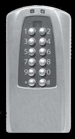

1 E-PLEX 5x70 Series Stand-Alone Access Controller Installation Instructions 1
2 Table of Contents STEP...PAGE Tools Required... 2 A-1 Wall Installation...4 A-2 Gang Box Installation... 5 B-1 System Components...6 C-1 Component Wiring Connections...6 D-1 Tamper and Security Features...16 E-1 Software Setting...18 F-1 Hard Rest Procedure...18 Warranty Card... 7 Template WARNING: The Master Code of this unit has been factory preset: 1, 2, 3, 4, 5, 6, 7, 8. To activate lock functions, the master combination must be changed at time of installation. Warning and Cautions IMPORTANT: Carefully inspect windows, doorframes, door, lights, etc. to ensure that the recommended procedures will not cause any damage. Kaba Access Control's warranty does not cover damages caused by installation. CAUTION: Wear safety glasses during installation. TOOLS REQUIRED Electric Drill/Screwdriver with Variable Speed and Torque Various Flat and Phillips Bits for Power Driver Wire Cutter/Stripper Small Straight (Flat Head) Manual Screwdriver Wall Anchors with #10 and or #6 Flat Head Screws or Masonry Screws Masonry or Wood Drill Bits for Various Surfaces For technical assistance please call TECH (8324) or
3 ACU PIU 3
4 A-1 Wall Installation A-1.1 Please place the template (located in the middle of this. manual) on mounting surface to ensure that there are no obstructions; this allows the keypad housing to be moved up, then in and down onto the base plate. Mark and drill four holes for wood screws, wall anchors, or masonry screws and a. 1 2" diameter cable hole. Remove the template. A-1.2 A-1.3 A-1.4 Thread the cable from the back of the Outside Housing,... through the large hole in the Shim and into the hole in the wall. Remove the two security screws from the bottom of the Backplate & Gasket using the small wrench provided in the bag. Slide the back down about one inch while pulling it away from the housing. Position Shim, Gasket & Backplate and fasten with #10 Flat Head screws in the four large holes or with two #6 Flat Head screws in the two smaller holes or any combination of each.. A minimum of two #6 screws is recommended. Push all excess cable into the wall. Hold the top of the Outside Housing about one inch above the top of the Baseplate that is now screwed to the wall and push until the Gasket is flush with the back edges of the Outside Housing. Now push in and down until the bottom of the Baseplate and the bottom of the. Outside Housing are flush. Use the wrench provided to replace the security screws. TEMPLATE SHIM BACKPLATE & GASKET OUTSIDE HOUSING WITH KEYPAD SECURITY SCREWS 4
5 A-2 Gang Box Installation A-2.1 Mount Gang Box on the wall referring to the Template to insure clearance above the box. This allows the Keypad. Housing to be moved up, then in and down onto the Baseplate. Mark and drill holes for wood screws, wall anchors, or masonry screws and a 1 2 " diameter cable hole. A-2.2 Thread the cable from the back of the Outside Housing... through the large hole in the Shim, into the hole in the Gang Box and into the wall. Remove the two security screws from the bottom of the Backplate & Gasket using the small wrench provided in the bag. Slide the back down about one inch while pushing it away from the housing. A-2.3 Position the Backplate & Gasket, sandwiching the Shim against the Gang Box and fasten the Backplate & Gasket with #6 Flat Head screws into the two smaller holes that line up with the holes in the Gang Box. A-2.4 Push all excess cable into the wall conduit. Hold the top of the Outside Housing about one inch above the top of the Baseplate that is now screwed to the Gang Box and push until the Gasket is flush with the back edges of the Outside Housing. Now push in and down until the bottom of the Baseplate and the bottom of the Outside Housing are flush. Use the wrench provided to replace the security screws. GANG BOX SHIM BACKPLATE & GASKET OUTSIDE HOUSING WITH KEYPAD SECURITY SCREWS 5
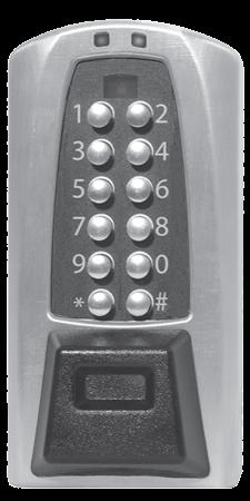
6 B SYSTEM COMPONENTS B-1 Kaba s E-Plex Stand-Alone Access Controller consists of the Access Control Unit (ACU) and the Power Interface Unit (PIU). It is typically used in conjunction with an off-the shelf door controller or power extender (not included) connected to. either a magnetic lock or electric strike for securing doors or. a parking gate for access control of parking areas. The door controller which must have battery back-up (manufactured by Securitron, Altronix, and others) is typically mounted on the inside wall next to the door or up in a drop ceiling for control of the door through interface with the magnetic lock or. electric strike. Door Controller (other) Kaba PIU Kaba ACU C COMPONENT WIRING CONNECTIONS C-1 Installation of this system is really quite simple. The door. controller is interfaced to the device that permits access to the door which typically provides support for either a. magnetic lock or electric strike, along with inputs for remote 6 exit (RE) and Fire alarm access.
7 KABA E-PLEX LIMITED WARRANTY Kaba Access Control warrants this product to be free from defects in material and workmanship under normal use and service for a period of three (3) years. Kaba Access Control will repair or replace, at our discretion, locks found by Kaba Access Control analysis to be defective during this period. Our only liability, whether in tort or in contract, under this warranty is to repair or replace products that are returned to Kaba Access Control within the three (3) year warranty period. This warranty is in lieu of and not in addition to any other warranty or condition, express or implied, including without limitation merchantability, fitness for purpose or absence of latent defects. ATTENTION: This warranty does not cover problems arising out of. improper installation, neglect or misuse. All warranties implied or written will be null and void if the lock is not installed properly and/or if any. supplied component part is substituted with a foreign part. If the lock is used with a wall bumper, the warranty is null and void. If a doorstop is required, we recommend the use of a floor secured stop. The environment and conditions of use determine the life of finishes on Kaba Access Control products. Finishes on Kaba Access Control products are subject to change due to wear and environmental corrosion. Kaba. Access Control cannot be held responsible for the deterioration. of finishes. Authorization to Return Goods Returned merchandise will not be accepted without prior approval.. Approvals and Returned Goods Authorization Numbers (RGA Numbers) are available through our Customer Service department in Winston-Salem, NC (800) The serial number of a lock is required to obtain this RGA Number. The issuance of an RGA does not imply that a credit or replacement will be issued. The RGA number must be included on the address label when material is returned to the factory. All component parts including latches and strikes (even if not inoperative) must be included in the package with return. All merchandise must be returned prepaid and properly packaged to the. address indicated. 7
8 For your records. Model No.: Date Purchased: Dealer: Name: Telephone: Notes For technical assistance please call TECH (8324) or
9
10 7.000 'B' 'W' 'W' 'B' 'W' 'W'
11 2 HOLES B, ARE SPACED FOR DUPLEX OUTLETS, WHEN MOUNTING TO A SINGLE GANG OUTLET BOX. ALIGN THE HOLE IN THE BACK OF THE BOX TO THE HOLE IN THE WALL MADE FOR THE CABLE, SCREW THE BACK OF THE BOX TO THE WALL, DRILL A 3/8" HOLE INTO A BLANK OUTLET COVER THEN THREAD THE CABLE THROUGH THE SUPPLIED SHIM PLATE, AND ON THROUGH THE BACK OF THE BOX INTO THE WALL HOLE, USE 2 #6 FLAT HEAD SCREWS TO GO THROUGH THE ACU S BASE HOLES THEN THROUGH THE BLANK COVER INTO THE SINGLE GANG BOX HOLES. (SCREWS NOT PROVIDED) AFTER THE SAC BASE IS SCREWED INTO PLACE, PRESS THE RUBBER BUMPER INTO THE SAC BASE HOLE TO ADHERE TO THE SUPPLIED SHIM PLATE BEFORE YOU SLIDE THE KEY- PAD HOUSING ONTO IT S BASE KABA ACCESS CONTROL TEMPLATE FOR KABA ACCESS MOUNTING CONTROL THE TEMPLATE ACCESS CONTROLLER FOR MOUNTING (ACU) THE ACCESS UNIT CONTROLLER (ACU) UNIT /2" HOLE FOR CABLE WHEN NOT MOUNTING TO AN OUTLET BOX, USE THESE 4 HOLE POSITIONS, W, TO LOCATE DRILL POINTS FOR WALL ANCHORS THAT USE #10 FLAT HEAD SCREWS. FOR MASONRY, 2 DIAGONAL HOLES MAY BE SUFFICIENT. (DO NOT OVERTIGHTEN AND WARP BASE) (WALL ANCHORS ARE NOT PROVIDED.) ALTER- NATIVELY, 4 PILOT HOLES FOR #10 WOOD SCREW FOR CLAPBOARD CONSTRUCTION MAY BE POSITIONED AT THESE LOCATIONS. THIS RECTANGULAR OUTLINE IS THE APPROXIMATE AREA THAT MUST BE CLEARED AROUND THE ACU. NOT TO SCALE 11
12
13 BUSINESS REPLY MAIL FIRST-CLASS MAIL PERMIT NO WINSTON-SALEM, NC POSTAGE WILL BE PAID BY ADDRESSEE KABA ACCESS CONTROL 2941 INDIANA AVENUE WINSTON-SALEM, NC NO POSTAGE NECESSARY IF MAILED IN THE UNITED STATES
14 REGISTRATION CARD Thank you for purchasing our product. In order to protect your investment and to enable us to better serve you in the future, please fill out this registration card and return it to Kaba Access Control, or register online at Name Position Company Address City State ZIP (Postal Code) Country Phone Name of Dealer Purchased From Date of Purchase Lock Model Number This lock will be used in what type of facility? Commercial Building Industrial / Manufacturing Airport College / University Government / Military School / Educational Hospital / Healthcare. Other (please specify) What area is being secured with this lock? (e.g. Front Door,. Common Door, Exercise Room) This lock is: New Installation Replacing a conventional keyed lock Replacing a Kaba Mechanical Pushbutton Lock Replacing a Kaba Electronic Access Control Replacing a Keyless Lock other than Kaba How did you learn about Kaba Access Control Pushbutton Locks? Advertisement Previous Use Internet / Web Another Use Locksmith Maintenance Training Class Other (please specify) What was your reason for buying this lock? Who installed your lock? Locksmith Maintenance Other Check here if you would like more information on Kaba Access Control locks.
15 C-2 The PIU requires a four (4) wire interface from the door. controller. Two wires provide +12 or +24 VDC to the power. interface unit and two wires support normally open (N.O.) switch closure from the power interface unit. DOOR CONTROLLER AND ALARM BOX ALTRONIX, SECURITRON, ETC. MAG OR STRIKE VDC + SECURITY ALARM BACK-UP BATTERY (ON INSIDE WALL) RED BLACK POWER FROM ALARM BOX SAC INTERFACE (IN P.I.U.) CONTROLLER INTERFACE J5 CONTACT CLOSURE BLACK RED + SW6 ALARM SW5 LOCK INTERFACE J6 RED BLACK ORANGE WHITE BLUE GREEN PURPLE J7 YELLOW CONTACT CLOSURE SHUNT RESET C-3 The interface between the PIU and the ACU requires an eight wire connection using the screw terminals on the interface board assembly inside the PIU enclosure. On the opposite. end, the eight wires are expanded inside the ACU which also. includes 10 feet of cable for ease of installation in most door installations. 15
16 C-4 Each of the wire colors is plainly labeled on the PIU s. interface board assembly next to the connector J6. (See Figure 1) The standard cable length is 10 feet. Typical installation will have Kaba s ACU mounted on the unsecured side of the wall next to the door controlled. The door. controller and Kaba s PIU are mounted on the secure side of the door. The ACU is designed to be mounted directly onto. different types of wall surfaces or on a single gang. electrical box. D TAMPER AND SECURITY FEATURES D-1 Kaba s Stand-Alone Access Controller has features built in that can provide an extra layer of security to the installa-..tion. The Shim Plate installed between the ACU and mounting surface has a bump that extends through a hole in the Backplate. This bump depresses a security switch in the controller to indicate that the installation is secure. If the ACU is opened, vandalized, or removed from the surface it is mounted to, the switch will trigger a disarming of the lock. If tampering is. detected by the ACU, the lights at the top of the unit will glow blue until the unit is reset. The ACU must be returned to the secure position and the reset button pressed on the PIU (See Figure 1) to restore the door access and operation. Since the reset occurs at the PIU which is on the secure side of the door, another point of access must be available. This feature may be disabled by turning the bottom switch on SW6 off. (Refer to Figure 3 on Page 19) D-2 Another feature of this lock is the SHUNT circuit. SW5 allows selection of one of four switches to control the duration of the Shunt. A SHUNT is typically used to indicate a valid access to a central alarm system. Different alarm systems require different period closures for this purpose and therefore the selections are.1,.2,.5, and 1 second duration. Only ONE switch may be selected. This SHUNT period is also part of the overall period selected for opening. If the SHUNT is one second and the period for opening is three seconds, the opening will only last 2 seconds. The door remains secure until the end of the SHUNT period. The SHUNT closure is factory set to normally open (N.O.) but may be changed by changing the jumper on J7 from 1->2 to 2->3. This will make the SHUNT. normally closed (N.C.). (See Figure 2) 16
17 Figure 1 (ON INSIDE WALL) DOOR CONTROLLER AND ALARM BOX ALTRONIX, SECURITRON, ETC. (ON INSIDE WALL) RED BLACK MAG OR STRIKE VDC + SECURITY ALARM BACK-UP BATTERY FIRE ALARM LOCKING DEVICE KABA Access Controll Unit (ACU) (ON OUTSIDE WALL) KABA POWER INTERFACE UNIT (P.I.U.) SAC INTERFACE (IN P.I.U.) 8 CONDUCTOR CABLE FROM SAC OUTSIDE (TO P.I.U.) POWER FROM ALARM BOX SAC INTERFACE (IN P.I.U.) CONTROLLER INTERFACE J5 CONTACT CLOSURE BLACK RED + SW6 ALARM SW5 SHUNT LOCK INTERFACE J6 RED BLACK ORANGE WHITE BLUE GREEN PURPLE YELLOW CONTACT CLOSURE FOIL CENTRAL ALARM (OPTIONAL) RESET DOOR Close-up SAC INTERFACE (IN P.I.U.) CONTROLLER INTERFACE J5 CONTACT CLOSURE BLACK RED + ALARM J7 LOCK INTERFACE J6 RED BLACK ORANGE WHITE BLUE GREEN PURPLE YELLOW CONTACT CLOSURE SHUNT J7 Figure 2 J7 SW6 SW RESET Factory Setting Normally Open (N.O.) Normally Closed (N.C.) 17
18 E Software Settings for Kaba s Stand-Alone Access Controller (SAC) E-1.. When configuring the E5070 series SAC using the optional.. Standard Software, choose the box that contains Entry Lock.. with Passage (Cylindrical or Mortise without Deadbolt) during.. lock setup. E-2 When configuring the E5270/5770 series SAC using the... mandatory ACS Software, select the Cylindrical or Mortise.. without Deadbolt box during lock setup. F Hard Reset Procedure for Kaba s Stand-Alone Access Controller (SAC) F-1.. A hard reset may be necessary if the master code for the lock.. is lost. A hard reset erases all user codes including the master user and all lock parameters go back to factory default. See the Operations Manual for information on other.. types of resets that can be performed at the ACU s keypad... This procedure requires two people within hearing range of.. each other to verify the sequence below. One person must.. have access to the Lock Interface board assembly inside the.. PIU enclosure on the secure side and another person must be.. located at the ACU unit on the non-secure side of the door... Steps 2, 3, and 4 below must be completed within 5 seconds 1. Person 1: Unlock and open cover to PIU unit 2. Person 1: Slide the TOP switch of SW6 on the PIU s Lock.. Interface board to ON (See Figure 3) 3. Person 2: Press the # key on the ACU s keypad 4. Person 1: Slide the TOP switch of SW6 on the PIU s Lock.. Interface board to OFF and close cover on PIU unit 5. Person 2: Observe Green and Red LEDs flashing on ACU 6. Person 2: Press on Keypad, then press # 7. The ACU is now in Factory Default Setup 18
19 SAC INTERFACE (IN P.I.U.) CONTROLLER INTERFACE J5 CONTACT CLOSURE BLACK RED + ALARM LOCK INTERFACE J6 RED BLACK ORANGE WHITE BLUE GREEN PURPLE J7 YELLOW CONTACT CLOSURE SHUNT 1 2 SW6 N O (TOP) (BOTTOM) SW6 SW5 Figure 3 RESET Notes For technical assistance please call TECH (8324) or
20 Kaba Access Control 2941 Indiana Avenue Winston-Salem, NC USA Tel: (800) (336) Fax: (800) (336) For Technical Assistance Tel: TECH (336) PKG
Model NT20e Installation Guide
 Model NT20e Installation Guide Rev 1.4 Page 2 of 14 1. Preparing for Installation CAUTION Do not remove the NT20e from the Electro-static bag until instructed from this installation guide. The NT20e is
Crypto-Lock. Model CC-8521B Updated 7/17. Access Control System. MONITEQ, Inc. INSTRUCTION MANUAL
 Crypto-Lock Model CC-8521B Updated 7/17 Access Control System INSTRUCTION MANUAL MONITEQ, Inc. 2 TABLE OF CONTENTS 1. INTRODUCTION..4 2. SPECIFICATIONS.....6 3. SUPPLIED EQUIPMENT.. 6 4. FUNCTIONS OF CONTROLS
WARNING Important Safety Information
 Builder Series Non-Programmable Thermostat MODEL 00NC Heat Only or Cool Only Thermostat Before Installing, Programming or Operating, PLEASE READ ALL INSTRUCTIONS Specifications Temperature Adjustment WARNING
HEIGHTS KEY LOCK & SAFE 920 San Mateo NE Albuquerque, NM Contact us for more information
 HEIGHTS KEY LOCK & SAFE 920 San Mateo NE Albuquerque, NM 87108 Contact us for more information Home Page FEATURES AND PROGRAMMING GUIDE COMMANDANDCONTROLSERIES DOOR-GARD COMMAND AND CONTROL SERIES keypads
FLCH4R Garage and Utility Electric Heater
 FLCH4R Garage and Utility Electric Heater Installation, Operation & Maintenance Instructions Model No. Volts Amps Watts BTU/HR Phase High Low High Low High Low Min Fuse Size* FLCH4R 208 17.3 8.66 3600
OWNERS MANUAL YEAR LIMITED WARRANTY READ ALL INSTRUCTIONS BEFORE PROCEEDING. Store this booklet for future reference
 3100 Premier Series Non-Programmable 2 Heat / 2Cool & Heat / Cool Digital Thermostat OWNERS MANUAL Compatible with low voltage multi-stage heat / cool systems with up to two stages of heating and two stages
USER MANUAL WARNING! CONTENTS MODEL SPECIFICATIONS READ ALL INSTRUCTIONS BEFORE PROCEEDING
 MODEL Premier Series 3000 USER MANUAL Non-Programmable Single Stage Heat/Cool Digital Thermostat Compatible with low voltage single stage gas, oil or electric heating or cooling systems, including single
OWNERS MANUAL YEAR LIMITED WARRANTY READ ALL INSTRUCTIONS BEFORE PROCEEDING. Store this booklet for future reference
 3000 Premier Series Non-Programmable Single Stage /Cool Digital Thermostat OWNERS MANUAL Compatible with low voltage single stage gas, oil or electric heating or cooling systems, including single stage
WARNING Important Safety Information
 1 Specifications Premier Series Non-Programmable Thermostats MODEL 3000 MODEL 3200 1 2 3 4 5 Specifications Installation Testing Your New Thermostat Programming User Settings Temperature Adjustment WARNING
LUMA-NET 804CP / 808CP REMOTE CONTROL PANEL
 LUMA-NET 804CP / 808CP REMOTE CONTROL PANEL INSTALLATION AND OPERATION GUIDE INTRODUCTION The NSI 804CP and 808CP represents a key part of a state of the art, total lighting control system. Combined with
WARNING Important Safety Information
 1 Specifications Premier Series Non-Programmable Thermostats MODEL 3000 MODEL 3200 1 2 3 4 Specifications Installation Testing Your New Thermostat Programming User Settings WARNING Important Safety Information
User s Manual and Warranty Information for Counterweighted Chain Drive ThyssenKrupp Access
 II User s Manual and Warranty Information for Counterweighted Chain Drive ThyssenKrupp Access Part #2139703 Rev. G II Table of Contents Introduction...3 Elevator Overview...4 Description of Features...5-7
WARNING Important Safety Information
 Builder Series Non-Programmable Thermostats MODEL 1000 MODEL 0 1 2 3 4 Single Stage Heat / Cool Conventional and Heat Pump Multi-Stage 2 Heat / 1 Cool Conventional and Heat Pump Before Installing, Programming
Document No
 CO Guardian LLC 1951 E. Airport Dr. Tucson, AZ 85706 CARBON MONOXIDE DETECTOR MODEL 452 INSTALLATION AND OPERATIONAL MANUAL Document No. 01-2510-02 MODEL 452 INSTALLATION AND OPERATIONAL MANUAL Page 1
VX SERIES Wireless Thermostat with Occupancy Sensor
 VX SERIES Wireless Thermostat with Occupancy Sensor INSTRUCTION MANUAL Table of Contents Thermostat Installation... 7 Installing the Wireless Control Card...8 Mounting the thermostat to the wall...9 Thermostat
IMPORTANT INFORMATION
 IMPORTANT INFORMATION ATTENTION PLEASE READ THIS INFORMATION CAREFULLY BEFORE OPERATING YOUR SPORTS AFIELD LIGHTNING HANDGUN VAULT. DO NOT LOCK THIS MANUAL OR THE OVERRIDE ACCESS KEYS IN YOUR VAULT. Thank
OWNERS MANUAL. CARBON MONOXIDE DETECTOR MODELS Panel Mount & Remote Detectors (R) Guardian Avionics 1951 E. AIRPORT DRIVE TUCSON, AZ.
 Guardian Avionics 1951 E. AIRPORT DRIVE TUCSON, AZ.") OWNERS MANUAL CARBON MONOXIDE DETECTOR MODELS Panel Mount & Remote Detectors (R) (353-101 and 353-201) 353 FAMILY MODEL OWNERS/INSTALLATION MANUAL Page 1 of 22 LOG OF REVISIONS REV NO. PAGE NO. DATE DESCRIPTION
OWNERS MANUAL CARBON MONOXIDE DETECTOR MODELS Panel Mount & Remote Detectors (R) (353-101 and 353-201) 353 FAMILY MODEL OWNERS/INSTALLATION MANUAL Page 1 of 22 LOG OF REVISIONS REV NO. PAGE NO. DATE DESCRIPTION
Warnings 2. Installation Instructions 3. Wiring Instructions 3. Mounting Instructions 4. Replacement Element Installation 5. Replacement Parts 5
 TABLE OF CONTENTS Warnings 2 Installation Instructions 3 Wiring Instructions 3 Mounting Instructions 4 Replacement Element Installation 5 Replacement Parts 5 Heater Coverage Areas 6 General Notes 6 Maintenance
Item no PERSONAL V2.0. User s Manual
 R Item no. 2260 PERSONAL 6 LITER FRIDGE/WARMER V2.0 User s Manual 6 Liter Personal Fridge/Warmer by Wagan Tech Padded Armrest Latching Lid Cupholders fold out LED Temperature Display High Power Cooling
CO Guardian LLC Document: E. AIRPORT DRIVE Date: 11/15/05 OWNERS MANUAL
 OWNERS MANUAL CARBON MONOXIDE DETECTOR MODELS Panel mount and Remote Detectors (R) (353 and 353R) 353 FAMILY MODEL OWNERS/INSTALLATION MANUAL Page 1 of 22 LOG OF REVISIONS REV NO. PAGE NO. DATE DESCRIPTION
Section 1: General Description. Section 2: Features. Section 3: Operation. CM-RQE70 PIR REQUEST TO EXIT DETECTOR Installation Instructions.
 CM-RQE70 PIR REQUEST TO EXIT DETECTOR Installation Instructions 1 PACKAGE CONTENTS Wiring Harness 6 Wire Nuts #6 x 3/4 Screws s BP7175 3/16 Wall Plugs Section 1: General Description Camden CM-RQE-70 Request-to-Exit
Proliphix Thermostat Installation Guide. Release 2.0
 Proliphix Thermostat Installation Guide Release 2.0 July 2006 Beta Draft Confidential Technical Support When contacting Proliphix for technical assistance, please have the following information available:
DIGITAL STEEL FIRE & SECURITY
 Models 2111-2115 DIGITAL STEEL FIRE & SECURITY Read this manual carefully and never store it inside the safe! Digital Steel Fire & Security Safe Models 2111-2115 PACKAGE CONTENTS 1 Digital Steel Fire &
Auto Opening with Pressure Readout 15 x15 & 16 x20 Heat Transfer Machines
 S-450P & S-650P Auto Opening with Pressure Readout 15 x15 & 16 x20 Heat Transfer Machines OWNER S MANUAL S-650P shown For Customer Service, Call 1-800-835-0606 or Visit www.hixcorp.com CONTENTS Receiving
LIGHTNING VAULT WALL MOUNT SINGLE HANDGUN
 LIGHTNING VAULT WALL MOUNT SINGLE HANDGUN IMPORTANT INFORMATION ATTENTION PLEASE READ THIS INFORMATION CAREFULLY BEFORE OPERATING YOUR SPORTS AFIELD LIGHTNING HANDGUN VAULT. DO NOT LOCK THIS MANUAL OR
INSTALLATION USE & CARE MANUAL ALL WEATHER SL-SERIES QUARTZ TUBE ELECTRIC INFRARED RADIANT HEATER
 INSTALLATION USE & CARE MANUAL ALL WEATHER SL-SERIES QUARTZ TUBE ELECTRIC INFRARED RADIANT HEATER TABLE OF CONTENTS IMPORTANT INFORMATION Warnings 2 Installation Instructions 3 Wiring Instructions 3 Outdoor
2 - Wire Programmable Digital Thermostat
 OWNER'S MANUAL P/N P474-1020 2 - Wire Programmable Digital Thermostat TOTALINE I2:34 72 HEAT 72 Heat only, or Cool only 2 - Wire Operation No Batteries Required Simple, Single Setpoint 7 Day Programmable
CO Guardian LLC Document No E. AIRPORT DRIVE Date: TUCSON, AZ CO Guardian LLC 1951 E. Airport Dr.
 1951 E. AIRPORT DRIVE Date: 8-20-2004 CO Guardian LLC 1951 E. Airport Dr. Tucson, AZ 85706 OWNERS MANUAL CARBON MONOXIDE DETECTOR MODEL 452-201 REMOTE UNIT MODEL 452-201 OWNERS MANUAL Page 1 of 22 INTENTIONALLY
240 ASSEMBLY & OPERATION MANUAL
 WineKoolRTM 240 Read the "USE and CARE" guide before you start! LOCATING YOUR WINE CELLAR Provide 2 1/2 Never locate your wine cellar outdoors or in an area with extremes of temperature and humidity. These
Model 3901T / 3902T / 3903T
 Vehicle Security System Model 3901T / 3902T / 3903T Owner s Guide Limited consumer warranty For a period of one calendar year from the date of purchase of this auto-security device, Directed Electronics,
OWNERS MANUAL MODEL 451 (-101 & -201)
") OWNERS MANUAL MODEL 451 (-101 & -201) Guardian Avionics CO Guardian, LLC. 1951 E Airport Drive Tucson, AZ 85756 Phone: 520-889-1177 8:00 am - 5:00 pm MST support@guardianavionics.com 2 Table of Contents
OWNERS MANUAL MODEL 451 (-101 & -201) Guardian Avionics CO Guardian, LLC. 1951 E Airport Drive Tucson, AZ 85756 Phone: 520-889-1177 8:00 am - 5:00 pm MST support@guardianavionics.com 2 Table of Contents
DE5300 Delayed Egress System. General Information
 *911031-00* 911031-00 Wiring and Configuration DE5300 Delayed Egress System Installation Instructions General Information The Von Duprin DE5300 is designed for controlled egress applications when used
Environmental Monitoring SmartSlot Card
 Environmental Monitoring SmartSlot Card AP9612TH Installation and Quick Start Manual Contents Introduction............................. 1 Overview 1 Product inventory 1 Safety notice 2 Your inspection
USER MANUAL 2000NC MODEL READ ALL INSTRUCTIONS BEFORE PROCEEDING. Builder Series 5-2 Day Programmable Single Stage Heat/Cool Digital Thermostat
 MODEL 2000NC USER MANUAL Builder Series 5-2 Day Programmable Single Stage /Cool Digital Thermostat Compatible with low voltage single stage gas, oil or electric heating or cooling systems, including single
Addendum for STI-6406 with Dual Access Control
 Addendum for STI-6406 with Dual Access Control Description: This system contains a STI-6400 with a DPDT key switch to be mounted on one side of a door or wall; and a similar looking housing, also with
WARNING Important Safety Information
 1 Specifications 1 2 3 4 5 Builder Series Programmable Thermostats 2000 2000NC 2200 2200NC Single Stage Heat / Cool Conventional and Heat Pump Multi-Stage 2 Heat / 1 Cool Conventional and Heat Pump Before
M770 ph Controller Owner s Manual
 M770 ph Controller Owner s Manual Table of Contents I. Introduction page 2 A. Water Chemistry page 2 B. Safety page 3 C. System Components page 4 D. Specifications page 7 E. Controller Panel Descriptions
ALL WEATHER SL-SERIES QUARTZ TUBE ELECTRIC INFRARED RADIANT HEATER INSTALLATION USE & CARE MANUAL
 ALL WEATHER SL-SERIES QUARTZ TUBE ELECTRIC INFRARED RADIANT HEATER TABLE OF CONTENTS: INSTALLATION USE & CARE MANUAL IMPORTANT INFORMATION Assembly Instructions 2 Wiring Instructions 2 Outdoor Installation
MGC Dock User s Manual
 User s Manual Contents Warnings Statements/Avertisseement... 3 READ FIRST BEFORE OPERATION... 3 Description... 4 Basic Operation... 5 Clip Dock Components... 5 LEDs... 5 User Operation... 6 Turning the
Installation Guide for models:
 140 58th St. Brooklyn, NY Access Power Controllers with Power Supplies Installation Guide for models: Maximal11F - Power Supply 1: 12VDC @ 3.3 amp or 24VDC @ 3.6 amp. - Power Supply 2: 12VDC @ 3.3 amp
USER MANUAL MODEL READ ALL INSTRUCTIONS BEFORE PROCEEDING. 5-2 Day Programmable Multi-Stage 2 Heat/1 Cool Heat Pump Digital Thermostat
 WARNING! Important Safety Information Builder MODEL 2200 Series 5-2 Day Programmable Multi-Stage 2 Heat/1 Cool Heat Pump Digital Thermostat USER MANUAL Compatible with low voltage multi stage heat/cool
FUME HOOD MONITOR ALNOR AIRGARD 200
 FUME HOOD MONITOR ALNOR AIRGARD 200 OWNER S MANUAL P/N 116670080, REV 09 SEPTEMBER 2014 LIMITATION OF WARRANTY AND LIABILITY (effective April 2014) (For country-specific terms and conditions outside of
OWNERS MANUAL YEAR LIMITED WARRANTY READ ALL INSTRUCTIONS BEFORE PROCEEDING. Store this booklet for future reference
 5100 Premier Series 7-Day Programmable 2-Heat / 2-Cool Heat /Cool Digital Thermostat OWNERS MANUAL Compatible with low voltage multi-stage heat / cool systems with up to two stages of heating and two stages
INSTALLATION USE & CARE MANUAL ALL WEATHER W-SERIES AND WD-SERIES QUARTZ TUBE ELECTRIC INFRARED RADIANT HEATER
 INSTALLATION USE & CARE MANUAL ALL WEATHER W-SERIES AND WD-SERIES QUARTZ TUBE ELECTRIC INFRARED RADIANT HEATER TABLE OF CONTENTS Warnings 2 Installation Instructions 3 Wiring Instructions 3 Mounting Instructions
OPTICAL TURNSTILE SYSTEM
 OPTICAL TURNSTILE SYSTEM Installation Instructions OTS-WNG UNPACK TURNSTILES. Remove the bolts at the ends of the turnstiles to separate from the skids and place turnstiles on the floor. With a box knife
Isolation Relay: If Needed. # 9. NO relay for TT To Thermostat NO relay. MZ308 Exquisite Heat Controller
 #4. 24 Volt AC & for 24 AC supply to thermostat if needed Isolation Relay: If Needed. # 9. NO relay for TT To Thermostat NO relay #12. To Thermistor for Domestic hot water Supply from boiler Orange & Brown
EcoBrite Smooth Light LED Light Fixtures
 Installation Guide EcoBrite Smooth Light LED Light Fixtures BEFORE YOU BEGIN INSTALLATION Read these instructions carefully. Failure to follow these instructions will invalidate the warranty on this product
Series. Access Power Controllers. Installation Guide
 Series Access Power Controllers Installation Guide Models Include: Maxim11 - Power Supply 1: 12VDC @ 3.5 amp or 24VDC @ 2.7 amp. - Power Supply 2: 12VDC @ 3.5 amp or 24VDC @ 2.7 amp. - Sixteen (16) fuse
KT-100 Door Controller
 WARNING: This manual contains information on limitations regarding product use and function and information on the limitations as to liability of the manufacturer. The entire manual should be carefully
ALM100 Alarm Module. User s Manual
 ALM100 Alarm Module User s Manual Revision 1.0 Copyright 2008 Maretron, LLP All Rights Reserved Maretron, LLP 9014 N. 23 rd Ave #10 Phoenix, AZ 85021-7850 http://www.maretron.com Maretron Manual Part #:
DEMA SOLID PRODUCT LAUNDRY MASTER TM MODEL: 581L-1W and 581L-2W INSTALLATION INSTRUCTIONS
 Included Parts: A. 581.1 Solid Bowl B. 58.1LA Vacuum Breaker C. 58.6 Stainless Steel Supply Tube D. 58.29 90º Compression Fitting E. 58.24 Straight Compression Fitting F. 58.7 Vinyl Discharge Tube G. 66.123
Module de relais Relay Module. Manuel de l utilisateur 301RW. User Manual ERP /07
 Module de relais Relay Module Manuel de l utilisateur 301RW User Manual ERP 511397 02/07 Relay Module 301R User Manual ERP 511397 2/07 Notices and Trademarks Copyright by Honeywell International Inc.
2010 Sedona Series Components
 LIMITED 90-DAY CONSUMER WARRANTY LIMITED TWO-YEAR CONSUMER WARRANTY WITH PURCHASE AND INSTALLATION BY A PRECISION POWER AUTHORIZED DEALER Precision Power promises to the original purchaser, to repair or
owner s manual MX650-CCX
 owner s manual MX650-CCX 6.50-inch (165 mm) Cockpit Coaxial Speaker Systems Thank you for purchasing a JL Audio Marine Coaxial Speaker System. With proper installation, your new speakers will deliver years
INSTRUCTION MANUAL TS21. 2 Heating and 1 Cooling
 INSTRUCTION MANUAL TS21 2 Heating and 1 Cooling WELCOME TO Flexible applications - Universal and easy to install in residential or commercial environments. Advanced features - Precision electronics provide
WATERSHIELIJrM REVERSE OSMOSIS INSTALLA TION MANUAL ~ ~ ~ ~ ~ l ~ TO INSURE THIS PRODUCT AND THE INSTALLATION THEREOF. ~ ~ ~ ~ ~
 WATERSHIELIJrM REVERSE OSMOSIS SYSTEM INSTALLA TION MANUAL p 1 ~ -~ I IMPORTANT I ITHIS REVERSE OSMOSIS SYSTEM WAS SOLD IN KIT FORM. IT HAS ~ INOT BEEN PRESSURE TESTED IN ANY WAY. UPON INSTALLATION IT
DIGITAL STEEL FIRE & SECURITY
 Models 2111-2115 DIGITAL STEEL FIRE & SECURITY Read this manual carefully and never store it inside the safe! Digital Steel Fire & Security Safe Models 2111-2115 PACKAGE CONTENTS 1 Digital Steel Fire &
Honeywell Garrett Drop-in Intercooler for 2.3L Mustang EcoBoost IMPORTANT INFORMATION - PLEASE READ CAREFULLY
 Honeywell Garrett Drop-in Intercooler for 2.3L Mustang EcoBoost Bill of Materials and Precautions Application: 2015+ Ford Mustang 2.3L EcoBoost Part Number: 857564-6001 Part List: Item Description QTY
User's Manual. and Warranty Information. ThyssenKrupp. ThyssenKrupp Access
 LIMITED WARRANTY Limited Warranty: Subject to the limitations set forth below, THYSSENKRUPP ACCESS, 4001 East 138th Street, Grandview, Missouri 64030, warrants to the ORIGINAL PURCHASER ONLY that the Volant
SC Installation, Operation & Application Guide
 SC 3006 Auto Changeover 7-Day Programmable Hardwired Programmable Electronic Thermostat 7-Day Programmable Single Stage Heat Pump/Non-Heat Pump Systems Backlit Display Single Stage Heat/Cool Systems Field
Hades 2. Digital Recycle and Lighting Timer with High Temp Shut-Off Instruction Manual. Notes: 1 Square = Foot/Feet
 Notes: 1 Square = Foot/Feet Hades 2 Digital Recycle and Lighting Timer with High Temp Shut-Off Instruction Manual VANCOUVER, WASHINGTON U.S.A. VANCOUVER, WASHINGTON U.S.A. www.titancontrols.net Revision
USER MANUAL WARNING! CONTENTS MODEL 1 SPECIFICATIONS READ ALL INSTRUCTIONS BEFORE PROCEEDING 2 INSTALLATION. Premier Series
 Premier Series MODEL 5000 USER MANUAL 5-2 Day Programmable Single Stage Heat/Cool Digital Thermostat Compatible with low voltage single stage gas, oil or electric heating or cooling systems, including
THUNDER LOW FREQUENCY AMPLIFIER INSTALLATION MANUAL
 THUNDER LOW FREQUENCY AMPLIFIER 655-0010-01-01 INSTALLATION MANUAL TABLE OF CONTENT PAGE NO General Description 2 Technical Specification 2 Mechanical Installation 4 Electrical Installation 6 Dip Switch
Installation & Operation Manual
 Installation & Operation Manual Radiant Thermostat 519 519_D 06/16 Zoning Replaces: 03/13 Introduction The Radiant Thermostat 519 accurately controls the room and/or floor temperature for a hydronic heating
MODEL B2 INSTALLATION MANUAL
 RELEASE DEVICES GENERAL DESCRIPTION MODEL B2 INSTALLATION MANUAL S/N: The B2 Series Time Delay Release Devices are UL Listed, Canadian Listed, and CSFM Listed for use on rolling doors, single-slide and
HI Industrial Utility Heater HI Soleus Air International
 HI1-50-03 Industrial Utility Heater HI1-50-03 2010 Soleus Air International Thank you for choosing a Soleus Air Utility Heater. This owner s manual will provide you with valuable information necessary
CORNELL Emergency Response Systems
 CORNELL Emergency Response Systems Door Monitor Systems Series 1000 CORNELL Communications, Inc. Milwaukee, WI USA 800-558-8957 - www.cornell.com rev 6/04 A-1000 SERIES DOOR MONITOR OPERATION AND WIRING
Warnings 2. Installation Instructions 3. Wiring Instructions 3. Mounting Instructions 4-5. Replacement Element Installation 5. Replacement Parts 5-6
 TABLE OF CONTENTS Warnings 2 Installation Instructions 3 Wiring Instructions 3 Mounting Instructions 4-5 Replacement Element Installation 5 Replacement Parts 5-6 Heater Coverage Areas 6 General Notes 6
AL400ULACM AL600ULACM - 4 amp - 12VDC or 6 amp. - Fused Outputs - Fused Outputs
 ACM Series Access Power Controllers with Power Supplies Installation Guide Models Include: AL400ULACM AL600ULACM - 12VDC @ 4 amp - 12VDC or 24VDC @ 6 amp. or 24VDC @ 3 amp - Fused Outputs - Fused Outputs
Model: M30. Owner s Operation Manual. For correct operation, please read this manual to familiarise yourself with the features.
 Model: M30 Owner s Operation Manual For correct operation, please read this manual to familiarise yourself with the features. Includes wiring diagram We recommend professional installation of this security
INSTALLATION AND OPERATION INSTRUCTIONS
 MODEL: RCT-MLT III INSTALLATION AND OPERATION INSTRUCTIONS INTRODUCTION IF YOU CANNOT READ OR UNDERSTAND THESE INSTALLATION INSTRUCTIONS DO NOT ATTEMPT TO INSTALL OR OPERATE This remote control system
Owner s Manual. PIR-1 IR Learner
 Owner s Manual PIR-1 IR Learner PIR-1 Owner s Manual 2010-2013 Universal Remote Control, Inc. The information in this owner s manual is copyright protected. No part of this manual may be copied or reproduced
Owner s Manual. 5 year parts limited warranty. See inside for details
 17728_AB02_OP_MAN_v2.qxd 30/5/07 16:42 Owner s Manual Page 1 5 year parts limited warranty See inside for details 17728_AB02_OP_MAN_v2.qxd 30/5/07 16:42 Page 2 1 Thank you for buying the. READ AND SAVE
HD-26, HD-36, HD-48 Heated Displays
 HD-26, HD-36, HD-48 Heated Displays This manual contains important information regarding your Admiral Craft unit. Please read this manual thoroughly prior to equipment set-up, operation and maintenance.
Instruction Manual US PAT: 6,824,069 6,786,421. Models: CT03TS21 CTO3TS32 CTO3TS32H
 Instruction Manual US PAT: 6,824,069 6,786,421 Models: CT03TS21 CTO3TS32 CTO3TS32H www.climatouch.com AED Electronics Inc. 5758 Royalmount Avenue Montreal, Quebec,Canada H4P 1K5 Technical Support: 1-866-90TOUCH
THE DAVENPORT CEILING FAN INSTALLATION INSTRUCTIONS
 THE DAVENPORT CEILING FAN INSTALLATION INSTRUCTIONS Please read and save these instructions The Davenport 8 P.O.Box 961008 Fort Worth, TX 76161 (817) 626-5483 FAX (817) 626-5540 IO171-04/08 QUORUM'S UNIQUE
shine TM Manual User guide and installation instructions The global leader in door opening solutions
 shine TM Manual User guide and installation instructions The global leader in door opening solutions Important notes Product features Product not designed for external use. Do not use a tool to force the
Power Locking Installation Manual
 Shop Manual V203 Please Copy Necessary Pages, and Store the Original Power Locking System PLRB-Pro Controller Flex Switch & Key Fobs Numeric Keyless Interface Power lock (Compartments) Power Locking Installation
The Extraordinaire OWNER S MANUAL. Orbital Ceiling Fan. Model No. OF110** READ AND SAVE THESE INSTRUCTIONS. Net Weight 14.5 lbs. or 6.59 kg.
 The Extraordinaire Orbital Fan WARNING: Support Directly From Building Structure Net Weight 14.5 lbs. or 6.59 kg. Model No. OF110** OWNER S MANUAL READ AND SAVE THESE INSTRUCTIONS Important Safety Instructions
DIGITAL. Operation & Installation Guide. Read These Instructions Very Carefully! Home and Office Security Safes MFFS2054DF84DF18DFE0809 ENGLISH
 Operation & Installation Guide MFFS2054DF84DF18DFE0809 ENGLISH Model 2054DF Model 2084DF Model 2118DF DIGITAL Read These Instructions Very Carefully! Home and Office Security Safes Index Overview of Your
USER MANUAL. Bottled Water Dispenser SAVE FOR FUTURE USE. Model #
 Model # 900161: Page 1 USER MANUAL Bottled Water Dispenser Model # 900161 TO REDUCE THE RISK OF INJURY AND PROPERTY DAMAGE, USER MUST READ THIS MANUAL BEFORE ASSEMBLING, INSTALLING & OPERATING DISPENSER.
Installation Instructions EFS Hand Washing Station
 Installation Instructions EFS Hand Washing Station Both water and soap are sequenced and dispensed from outlet. Override button allows for non potable, water-only dispensing. Lighted icons indicate the
GG-EM ENTRANCE MONITOR. Installation and Operation Manual
 GG-EM ENTRANCE MONITOR Installation and Operation Manual 2 GG-EM Warning Use this product only in the manner described in this manual. If the equipment is used in a manner not specified by Calibration
SEABREEZE. SeaBreeze Rain Shower System Model #1086-CH Owner's Manual
 SEABREEZE SeaBreeze Rain Shower System Model #1086-CH Owner's Manual SeaBreeze Model #1086 Please Read The Following Instructions COMPLETELY Before Beginning! Our goal is to ensure your installation goes
232xt Wiring Diagrams and Specifications SPECIFICATIONS: REV 1.01
 232xt Wiring Diagrams and Specifications Voltage Selection Settings 1 2 3 Wire Xtreme Pad color to color to the wires on Programmer (Red to Red, ect.) ( / Yellow ) Position 12-24VA 15-24VD P5* Position
Modular Fillerplate Subassembly P/N: X Endcap P/N: Strike *, P/N: " Narrow Stile Plastic Template. Mortise.
 103182 June 3, 2010 Delayed Egress Parts Check List V40 EM Centercase/Pushpad Modular SubAssembly P/N: 104374-X Plastic Template Use for ease of installation P/N: 103806-X Detex Corporation, 302 Detex
Installation & Operation Manual
 Humidity & Temperature Sensor 086 Accessories 086_D 08/12 Replaces: New Installation & Operation Manual Introduction The Humidity & Temperature Sensor 086 can be connected to select tekmar thermostats
Model 405 AIRGARD Fume Hood Monitor
 INSTALLATION AND MAINTENANCE INSTRUCTIONS Model 405 AIRGARD Fume Hood Monitor A TSI Company Model 405 AIRGARD Fume Hood Monitor Specifications Instrument Dimensions Instrument Weight Shipping Weight Green
Owner s Manual LIMITED WARRANTY INFORMATION OBTAINING WARRANTY SERVICE FURTHER LIMITATIONS AND EXCLUSIONS ARE AS FOLLOWS REGISTRATION
 LIMITED WARRANTY INFORMATION Your DUCT PURE (Product) is warranted to be free from all defects in material and workmanship in normal household use for a period of 2 Years from date of purchase. The warranty
Environmental Monitoring Card
 Environmental Monitoring ard AP9612TH Installation and Quick-Start Manual ontents Introduction............................. 1 Overview............................. 1 Product inventory......................
For Android devices MYQ-G0301 MYQ-G0301C MYQ-G0301D MYQ-G0301LA
 Smart Smart Garage Garage Hub Hub Manual Manual For Android devices MYQ-G0301 MYQ-G0301C MYQ-G0301D MYQ-G0301LA by Before You Start To reduce the risk of SEVERE INJURY to persons: DO NOT enable the MyQ
ACM8 & ACM8CB. Access Power Controllers Installation Guide. - Fused Outputs - Fused Outputs. - PTC Outputs - PTC Outputs. Models Include: Rev.
 ACM8 & ACM8CB Access Power Controllers Installation Guide Models Include: ACM8 ACM8E - Fused Outputs - Fused Outputs ACM8CBE ACM8CB - PTC Outputs - PTC Outputs Rev. 092503 Overview: These units convert
WALL MOUNTED ELECTRIC FIREPLACE HEATER. Model # : Onyx Ivory Mirror OWNER S MANUAL. AC V 60Hz 1500W
 WALL MOUNTED ELECTRIC FIREPLACE HEATER Model # : 80001 Onyx 80002 Ivory 80008 - Mirror OWNER S MANUAL AC 110-120V 60Hz 1500W WARNING Read and understand this entire owner s manual, including all safety
Installation Guide for models:
 140 58th St. Brooklyn, NY Access Power Controllers with Power Supplies Installation Guide for models: Maximal3FD - 12VDC @ 4.6 amp or 24VDC @ 5.2 amp. - Sixteen (16) PTC protected power-limited outputs.
ACSI MODEL 1410 POWER SUPPLY INSTALLATION INSTRUCTIONS
 II 1400-3 ACSI MODEL 1410 POWER SUPPLY INSTALLATION INSTRUCTIONS Features: For use with doors or groups of doors that must interlock with each other to regulate control of accessing one area from another,
636 and 646 Keypads. User s Manual
 636 and 646 Keypads 636 646 User s Manual Table Of Contents Basic Operation... 2 Access Codes... 4 Arming & Disarming... 5 Panic Zones... 11 Key Access Programming... 12 Additional Features... 13 Trouble
WVD100. EZ Loop. Product Manual. Wireless Vehicle Detector. Installation Instructions Program Instructions. AP100 Relay Board S200 Sensor
 Wireless Vehicle Detector EZ Loop AP100 Relay Board S200 Sensor ACCESS STATUS < ONE PROGRAM Installation Instructions Program Instructions! Read and follow all U.L. and Safety Standards before installing
MGC Dock User s Manual
 Operator s Manual Contents Warnings Statements/Avertisseement... 3 READ FIRST BEFORE OPERATION... 3 Basic Operation... 4 Clip Dock Components... 4 LEDs... 4 Operation... 5 Turning the Clip Dock On and
INSTRUCTION MANUAL P Heating and 1 Cooling
 REPLACEMENT COMPONENTS DIVISION CARRIER CORPORATION www.totaltouch.info Technical Support: 1-866-90TOUCH (1-866-908-6824) INSTRUCTION MANUAL P286-1200 2 Heating and 1 Cooling Physical Dimensions Case:
Remote Chexit Module (RCM) System. General Information
 System. General Information") *911032-00* 911032-00 Wiring and Configuration Remote Chexit Module (RCM) System Installation Instructions General Information The Von Duprin RCM is designed for controlled egress applications. It meets
*911032-00* 911032-00 Wiring and Configuration Remote Chexit Module (RCM) System Installation Instructions General Information The Von Duprin RCM is designed for controlled egress applications. It meets