Update all extract references to NFPA documents (including NFPA 72) in Chapter 3 and related annex material to the latest editions.
|
|
|
- Garry Sutton
- 5 years ago
- Views:
Transcription
1 11/16/12 TerraView First Revision No. 15-NFPA [ Global Input ] Update all extract references to NFPA documents (including NFPA 72) in Chapter 3 and related annex material to the latest editions. Submittal Date: Wed Sep 26 16:13:45 EDT 2012 Committee Statement: Response Message: FR-15-NFPA Extract references to other NFPA documents should be to the latest edition. First Revision No. 16-NFPA [ Global Input ] Update all NFPA document references in Chapter 2 and Annex C to the latest edition. Submittal Date: Wed Sep 26 16:30:47 EDT 2012 Committee Statement: The latest revsion should be used for all NFPA documented listed in Chapter 2. Response Message: FR-16-NFPA /48
2 11/16/12 TerraView First Revision No. 9-NFPA [ Section No ] [Carbon Monoxide] Safety Control Functions. Building and [carbon Carbon monoxide] control functions that are intended to elements or systems that are initiatied by the [carbon monoxide detection] system and either increase the level of life safety for occupants or to control the spread of the harmful effects of [carbon monoxide]. [72, 2010] 2013] 3.3.6* [Carbon Monoxide] Control Function Interface Device. A listed [carbon monoxide detection] system component that directly interfaces with the system that operates the [carbon monoxide] control function. [ 72, 2013] Submittal Date: Wed Sep 26 14:57:32 EDT 2012 The definition for the term carbon monoxide control function is extracted from the definition of emergency control function in the 2013 edition of NFPA. The terminology has been modified to be consistent with that used in NFPA 720 while retaining the basic content of the definition. This term is used in Chapter 5. A new Committee term, "carbon monoxide control function interface device," and defintion has been Statement: added and extracted from the definitiion of emergency control function interface device in the 2013 edition of NFPA 72. The terminology has been modified to be consistent with that used in NFPA 720 while retaining the basic content of the definition.this term is used in Chapter 5 and Chapter 8. Response Message: FR-9-NFPA Committee Notes: Date Sep 26, 2012 Submitted By [ Not Specified ] The second definition was intended as a separate FR (FR 10) but staff had trouble making this work 2/48
3 11/16/12 TerraView First Revision No. 12-NFPA [ New Section after ] Occupiable. A room or enclosed space designed for human occupancy. [72, 2013] Occupiable Area. An area of a facility occupied by people on a regular basis. [72, 2013] Submittal Date: Wed Sep 26 15:57:30 EDT 2012 Committee New terms, "occupiable," and "occupiable area" and definitions have been added Statement: and extracted from the 2013 edition of NFPA 72. This terms are used in Chapter 6. Response Message: FR-12-NFPA /48
4 First Revision No. 13-NFPA [ Section No ] Trouble Signal. A signal initiated by a system or device indicative of a fault in a monitored circuit, system, or component. [ 72, 2010] Submittal Date: Wed Sep 26 16:03:47 EDT 2012 The extract reference has been removed. The changes made to in NFPA Committee concerning the terms "condition, signal, response" were not adopted in NFPA 720 Statement: and thus the revised definition in NFPA is therefore not appropriate in NFPA 720 and is no longer extracted. Response Message: FR-13-NFPA First Revision No. 14-NFPA [ Section No ] Supplementary. As used in this Code standard, supplementary refers to equipment or operations not required by this Code standard and designated as such by the authority having jurisdiction. [72, 2010] Submittal Date: Wed Sep 26 16:11:16 EDT 2012 Committee Statement: Editorial Response Message: FR-14-NFPA /48
5 11/19/12 TerraView First Revision No. 17-NFPA [ Section No ] [Carbon monoxide detection] system System components shall be installed, tested, inspected and maintained in accordance with the manufacturer s published instructions and this standard. [72:10.3.2] Submittal Date: Thu Sep 27 08:38:34 EDT 2012 Committee Statement: Response Message: FR-17-NFPA The extracted provision has been updated to be consistent with NFPA /1
6 11/19/12 TerraView First Revision No. 18-NFPA [ Section No. 4.4 ] 4.4 Personnel Qualifications System Designer Carbon monoxide detection system plans and specifications shall be developed in accordance with this standard by persons who are knowledgeable and experienced in the proper design, application, installation, and testing of the systems Where available, state or local licensure regulations shall be followed to determine qualified personnel Depending on state or local licensure regulations, qualified personnel shall be permitted to include, but not be limited to, one or more of the following: (1) Personnel who are factory trained and certified for carbon monoxide detection system design of the specific type and brand of system being designed and who are acceptable to the authority having jurisdiction (2) Personnel with expertise in the design of carbon monoxide systems that are registered, licensed, or certified by a state or local authority The system designer shall provide evidence of qualifications and/or certifications when requested by the authority having jurisdiction The system designer shall be identified on the system design documents. [72: ] System Installer [Carbon monoxide detection] system installation personnel shall be qualified or shall be supervised by persons who are qualified in the installation, inspection, and testing of the systems. [72: ] Where available, state or local licensure regulations shall be followed to determine qualified personnel Depending on state or local licensure regulations, qualified personnel shall be permitted to include, but not be limited to, one or more of the following: (1) Personnel with expertise in the installation of carbon monoxide systems that are registered, licensed, or certified by a state or local authority (2) Personnel who are factory trained and certified for carbon monoxide detection system installation of the specific type and brand of system being installed and who are acceptable to the authority having jurisdiction The system installer shall provide evidence of qualifications and/or certifications when requested by the authority having jurisdiction Inspection, Testing, and Maintenance Personnel * 1/2
7 * Service personnel shall be qualified and experienced in the inspection, testing, and maintenance of systems addressed within the scope of this standard Qualified personnel shall be permitted to include, but not be limited to, one or more of the following: (1) (2) * Personnel who are factory trained and certified for the specific type and brand of system being serviced * Personnel who are registered, licensed, or certified by a state or local authority to perform service on systems addressed within the scope of this standard (3) Personnel who are employed and qualified by an organization listed by a nationally recognized testing laboratory for the servicing of systems within the scope of this standard Evidence of qualifications shall be provided to the authority having jurisdiction upon request. [72: ] Submittal Date: Thu Sep 27 08:43:46 EDT 2012 Section 4.4 has been updated to be more specific to carbon monoxide detection systems. The extract designations for most of this material have been removed because Committee the provisions in NFPA 720 are different than those of NFPA 72. Section has been Statement: completely deleted since the scope of NFPA 720 addresses supervising station requirements primarily by reference - see Chapter 7. The provisions for supervising stations are fully addressed in NFPA 72. Response Message: FR-18-NFPA /2
8 First Revision No. 21-NFPA [ Section No. 4.5 ] 4.5 Power Supplies Scope. The provisions of this section shall apply to power supplies used for carbon monoxide detection systems Code Conformance. All power supplies shall be installed in conformity with the requirements of NFPA 70, National Electrical Code, for such equipment and with the requirements indicated in this subsection. [72:10.6.2] Power Supply Sources Power shall be supplied in compliance with either or [72: ] Unless configured in compliance with 4.5.4, at least two independent and reliable power supplies shall be provided, one primary and one secondary. [72: ] Each power supply shall be of adequate capacity for the application. [72: ] Monitoring the integrity of power supplies shall be in accordance with [72: ] Uninterruptible Power Supplies (UPS) The UPS device shall be configured in compliance with NFPA 111, Standard on Stored Electrical Energy Emergency and Standby Power Systems, for a Type O, Class 24, Level 1 system. [72: ] The UPS device shall comply with the requirements of [72: ] Failure of the UPS shall result in the initiation of a trouble signal in accordance with Section 4.9. [72: ] Primary Power Supply Branch Circuit. The branch circuit suppying the [carbon monoxide] equipment(s) [ ] shall supply no other loads and shall be supplied by one of the following: (1) Commercial light and power (2) An engine-driven generator or equivalent in accordance with , where a person specifically trained in its operation is on duty at all times (3) An engine-driven generator or equivalent arranged for cogeneration with commercial light and power in accordance with , where a person specifically trained in its operation is on duty at all times [72: ] Circuit Identification and Accessibility.
9 11/19/12 TerraView The location of the branch circuit disconnecting means shall be permanently identified at the control unit. [72: ] The circuit disconnecting means shall be clearly marked and shall be accessible only to authorized personnel Mechanical Protection. The branch circuit(s) and connections shall be protected against physical damage. [72: ] Overcurrent Protection. An overcurrent protective device of suitable current-carrying capacity that is capable of interrupting the maximum short-circuit current to which it can be subject shall be provided in each ungrounded conductor. [72: ] Secondary Power Supply * Secondary Power Supply for Protected Premises [Carbon Monoxide Detection] Systems The secondary power supply shall consist of one of the following: (1) A storage battery dedicated to the [carbon monoxide detection] system arranged in accordance with (2) An automatic-starting, engine-driven generator serving the branch circuit specified in and arranged in accordance with , and storage batteries dedicated to the [carbon monoxide detection] system with 4 hours of capacity arranged in accordance with [72: ] Secondary circuits that provide power to the control unit and are not integral to the unit shall be protected against physical damage. [72: ] Capacity * Where a combination (fire) system is used, the secondary power supply capacity requirements shall comply with and with those of NFPA 72, National Fire Alarm and Signaling Code * Where a combination carbon monoxide detection system is used, the secondary power supply capacity requirements shall comply with and with the provisions of the applicable NFPA code or standard The secondary power supply shall have sufficient capacity to operate the carbon monoxide detection system under quiescent load (system operating in a nonalarm condition) for a minimum of 24 hours and, at the end of that period, shall be capable of operating the carbon monoxide detection system and all notification appliances for 12 hours. Notification appliances shall perform in accordance with Exception : The 12-hour requirement shall be permitted to be reduced to 5 minutes where the system is monitored by a supervising station and emergency response in accordance with is provided. 2/6
10 11/19/12 TerraView For systems not addressed by through , the secondary power supply capacity required shall include all power supply loads that are not automatically disconnected upon the transfer to the secondary power supply Secondary Power Operation. Operation on secondary power shall not affect the required performance of a carbon monoxide detection system * Continuity of Power Supplies The secondary power supply shall automatically provide power to the protected premises system within 10 seconds whenever the primary power supply fails to provide the minimum voltage required for proper operation. [72: ] Required signals shall not be lost, interrupted, or delayed by more than 10 seconds as a result of the primary power failure. [72: ] Storage batteries dedicated to the [carbon monoxide detection] system or an uninterruptible power supply (UPS) arranged in accordance with the provisions of NFPA 111, Standard on Stored Electrical Energy Emergency and Standby Power Systems, shall be permitted to supplement the secondary power supply to ensure required operation during the transfer period. [72: ] Where a UPS is employed in , a positive means for disconnecting the input and output of the UPS system while maintaining continuity of power supply to the load shall be provided. [72: ] Power Supply for Remotely Located Control Equipment * Additional power supplies, where provided for control units, circuit interfaces, or other equipment essential to system operation, and located remotely from the main control unit, shall be comprised of a primary and secondary power supply that shall meet the same requirements as those of through and [72: ] The location of any remotely located power supply shall be identified at the master control unit. [72: ] The master control unit display shall be permitted to satisfy the requirement of [72: ] The location of any remotely located power supply shall be identified on the record drawings. [72: ] Storage Batteries Marking Batteries shall be marked with the month and year of manufacture using the month/year format. [72: ] 3/6
11 11/19/12 TerraView Where the battery is not marked with the month/year by the manufacturer, the installer shall obtain the date-code and mark the battery with the month/year of battery manufacture. [72: ] Location. Storage batteries shall be located so that the [carbon monoxide detection] equipment, including overcurrent devices, are not adversely affected by battery gases and shall conform to the requirements of NFPA 70, National Electrical Code, Article 480. [72: ] Cells shall be suitably insulated against ground-faults. [72: ] Cells shall be suitably insulated against crosses. [72: ] Cells shall be mounted in such a manner so as to be protected from physical damage. [72: ] Racks shall be suitably protected against deterioration. [72: ] If not located in or adjacent to the [carbon monoxide detection] control unit, the batteries and their charger location shall be permanently identified at the [carbon monoxide detection] control unit. [72: ] Battery Charging Adequate facilities shall be provided to automatically maintain the battery fully charged under all conditions of normal operation. [72: ] Adequate facilities shall be provided to recharge batteries within 48 hours after fully charged batteries have been subject to a single discharge cycle as specified in [72: ] Upon attaining a fully charged condition, the charge rate shall not be so excessive as to result in battery damage. [72: ] Supervising stations shall maintain spare parts or units available, which shall be used to restore failed charging capacity prior to the consumption of one-half of the capacity of the batteries for the supervising station equipment. [72: ] Overcurrent Protection The batteries shall be protected against excessive load current by overcurrent devices. [72: ] The batteries shall be protected from excessive charging current by overcurrent devices or by automatic current-limiting design of the charging source. [72: ] Metering. The charging equipment shall provide either integral meters or readily accessible terminal facilities for the connection of portable meters by which the battery voltage and charging current can be determined. [72: ] Monitoring Integrity of Battery Charger. 4/6
12 11/19/12 TerraView Means for monitoring integrity appropriate for the batteries and charger employed shall be provided to detect a battery charger failure. [72: ] Failure of the battery charger shall result in the initiation of a trouble signal in accordance with Section 4.9. [72: ] Engine-Driven Generators Application and Installation. The application and installation of engine-driven generators shall be as specified in through [72: ] Primary Power Supply Engine-driven generators arranged as the primary supply shall be designed in an approved manner. [72: ] Engine-driven generators arranged as the primary supply shall be installed in an approved manner. [72: ] Secondary Power Supplies Engine-driven generators used to provide secondary power for a [carbon monoxide detection] system shall comply with NFPA 110, Standard for Emergency and Standby Power Systems, Chapter 4, requirements for a Type 10, Class 24, Level 1 System. [72: ] Installation of engine-driven generators used to provide secondary power for a [carbon monoxide detection] system shall be in accordance with NFPA 70, National Electrical Code, Article 700. [72: ] Performance, Operation, Testing, and Maintenance. The requirements for performance, operation, testing, and maintenance of engine-driven generators shall conform to the applicable provisions of NFPA 110, Standard for Emergency and Standby Power Systems. [72: ] Capacity. The unit shall be of a capacity that is sufficient to operate the system under the maximum normal load conditions in addition to all other demands placed upon the unit. [72: ] Fuel. Unless otherwise required or permitted in through , fuel shall be available in storage sufficient for 6 months of testing plus the capacity specified in [72: ] If a reliable source of supply is available at any time on a 2-hour notice, it shall be permitted to have fuel in storage sufficient for 12 hours of operation at full load. [72: ] Fuel systems using natural or manufactured gas supplied through reliable utility mains shall not be required to have fuel storage tanks unless located in seismic risk zone 3 or greater as defined in ANSI A-58.1, Building Code Requirements for Minimum Design Loads in Buildings and Other Structures. [72: ] Battery and Charger. A separate storage battery and separate automatic charger shall be provided for starting the engine-driven generator and shall not be used for any other purpose. [72: ] 5/6
13 11/19/12 TerraView Submittal Date: Thu Sep 27 09:34:17 EDT 2012 Committee Statement: Response Message: Section 4.5 extracts have been updated to be consistent with the changes in NFPA FR-21-NFPA /6
14 First Revision No. 22-NFPA [ Section No. 4.6 ] 4.6 Distinctive Signals Carbon monoxide alarm signals and carbon monoxide detection system supervisory and trouble signals shall be distinctively and descriptively annunciated Audible alarm notification appliances for a [carbon monoxide detection] system shall produce signals that are distinctive from other similar appliances used for other purposes in the same area that are not part of the [carbon monoxide detection] system. [72: ] 4.6.3* Audible signals on An audible notification appliance on a control unit, or on multiple control units that are interconnected to form a system, or at a remote location, shall be permitted to have the same audible characteristics for all alerting functions including, but not limited to, alarm, trouble, and supervisory, provided that the distinction between signals shall be by other appropriate means, such as visible annunciation. [72: ] 4.6.4* Supervisory signals shall be distinctive in sound from other signals, and their sound shall not be used for any other purpose except as permitted in [72: ] Trouble signals required to indicate at the protected premises shall be indicated by distinctive audible signals, which shall be distinctive from alarm signals except as permitted in [72: ] When a carbon monoxide detection system is combined with either a fire alarm system and/ or an intrusion detection system, trouble signals from each system shall be permitted to use a common audible signal. Submittal Date: Thu Sep 27 10:37:44 EDT 2012 Committee Statement: Response Message: The extract provisions have been updated to be consistent with the changes in NFPA FR-22-NFPA
15 11/19/12 TerraView First Revision No. 23-NFPA [ Section No. 4.7 ] 4.7 Alarm Signals Carbon monoxide alarm signals shall comply with An alarm signal that has been deactivated at the protected premises shall comply with and [72: ] The audible and visible alarm signal at the control unit only shall automatically reactivate every 24 hours or less until alarm signal conditions are restored to normal. [72: ] The audible and visible alarm signal shall operate until it is manually silenced or acknowledged. [72: ] [Carbon Monoxide] Alarm Notification Appliance Deactivation. A means for turning off activated alarm notification appliance(s) shall be permitted only if it complies with through Exception : An initiating device with integral sounder shall be permitted to comply with When an oocupant notification alarm signal deactivation means is actuated, both audible and visible notification appliances shall be simultaneously deactivated. [72: ] The [carbon monoxide] alarm notification deactivation means shall be key-operated or located within a locked cabinet, or arranged to provide equivalent protection against unauthorized use. [72: ] The means shall comply with the requirements of [72: ] Subsequent actuation of initiating devices on other initiating device circuits or subsequent actuation of addressable initiating devices on signaling line circuits shall cause the notification appliances to reactivate. Exception : Subsequent actuation of another addressable initiating device of the same type in the same room or space shall not be required to cause the notification appliance(s) to reactivate A [carbon monoxide] alarm notification deactivation means that remains in the deactivated position when there is no alarm condition shall operate an audible trouble notification appliance until the means is restored to normal. [72: ] * Resetting of alarm signals shall comply with the requirements of [72: ] Submittal Date: Thu Sep 27 10:43:32 EDT /2
16 11/19/12 TerraView Except as noted, the extract provisions have been updated to be consistent with the changes in NFPA The revised language in of NFPA have not Committee been adopted in of NFPA 720 because removal of the referenced subsections Statement: provides ambiguous code language. Also, the revised language in of NFPA is not appropriate for of NFPA 720. Different types of fire alarm initiating device are not comparable to different type of CO initiating device. Response Message: FR-23-NFPA /2
17 11/19/12 TerraView First Revision No. 24-NFPA [ Section No. 4.8 ] 4.8 Supervisory Signals Supervisory Signal Indication. Visible and audible indication of supervisory signals and visible indication of their restoration to normal shall be indicated within 90 seconds at the following locations: (1) Control unit for local carbon monoxide detection systems (2) Building command center for emergency voice/alarm communications systems (3) Supervising station location for systems installed in compliance with Chapter Self-Restoring Signal. A supervisory signal initiating device shall be permitted to be self-restoring provided the control panel continues to indicate the supervisory condition Supervisory Notification Appliance Location. The audible supervisory notification appliances shall be located in an area where they are likely to be heard. [72: ] Supervisory Signal Reactivation. A supervisory signal that has been deactivated at the protected premises shall comply with and [72: ] The audible and visible supervisory signal at the control unit only shall automatically reactivate every 24 hours or less until supervisory signal conditions are restored to normal. [72: ] The audible and visible supervisory signal shall operate until it is manually silenced or acknowledged. [72: ] Supervisory Notification Appliance Deactivation A means for deactivating a supervisory notification appliance(s) shall be permitted only if it complies with through The means shall be key-operated or located within a locked cabinet, or arranged to provide equivalent protection against unauthorized use. [72: ] The means for deactivating supervisory notification appliances shall comply with the requirements of [72: ] Subsequent actuation of supervisory initiating devices in other building zones shall cause supervisory notification appliances to actuate as required by the system input/output matrix. [72: ] A means for deactivating supervisory notification appliances that remain in the deactivated position when there is no supervisory condition shall operate an audible trouble notification appliance until the means is restored to normal. [72: ] 1/2
18 11/19/12 TerraView Submittal Date: Thu Sep 27 11:39:01 EDT 2012 Except as noted, the extract provisions have been updated to be consistent with the Committee changes in NFPA The revised language in of NFPA have not Statement: been adopted in of NFPA 720 because removal of the referenced subsections provides ambiguous code language. Response Message: FR-24-NFPA /2
19 11/19/12 TerraView First Revision No. 25-NFPA [ Section No. 4.9 ] 4.9 Trouble Signals Trouble signals and their restoration to normal shall be indicated within 200 seconds at the locations identified in [72: ] Indication of primary power failure trouble signals transmitted to a supervising station shall be in accordance with [72: ] An audible trouble signal shall be permitted to be intermittent provided it sounds at least once every 10 seconds, with a minimum duration of 1 /2 second. [72: ] A single audible trouble signal shall be permitted to annunciate multiple fault conditions. [72: ] The audible trouble notification appliances shall be located in an area where they are likely to be heard. [72: ] Actuated notification appliances at the protected premises shall continue to operate unless they are manually silenced as permitted by [72: ] Visible and audible trouble signals and visible indication of their restoration to normal shall be indicated at the following locations: (1) Control unit for carbon monoxide detection systems (2) Building command center for emergency voice/alarm communications systems (3) Supervising stations for systems installed in compliance with Chapter * A trouble signal that has been deactivated at the protected premises shall comply with and [72: ] The audible and visible trouble signal shall automatically reactuate at the control unit every 24 hours or less until trouble signal conditions are restored to normal. [72: ] The audible and visible trouble signal associated with signaling the depletion or failure of the primary battery of a wireless system as required by (3) and (4) shall automatically resound every 4 hours or less until the depletion signal is restored to normal. [72: ] Trouble Notification Appliance Deactivation. 1/2
20 11/19/12 TerraView A means for deactivating trouble notification appliance(s) shall be permitted only if it complies with through The means shall be key-operated or located within a locked cabinet, or arranged to provide equivalent protection against unauthorized use. [72: ] The means for deactivating trouble notification appliances shall comply with the requirements of [72: ] If an audible trouble notification appliance is also used to indicate a supervisory condition, as permitted by 4.6.3, a trouble notification appliance deactivation means shall not prevent subsequent actuation of supervisory notification appliances. [72: ] Subsequent trouble signals shall cause trouble notification appliances to activate as required by the system input/output matrix. [72: ] A means for deactivating trouble notification appliances that remains in the deactivated position when there is no trouble condition shall operate an audible trouble notification appliance until the means is restored to normal. [72: ] Unless otherwise permitted by the authority having jurisdiction, trouble notification appliances at the protected premises of a supervising station [ ] alarm system arranged in accordance with Chapter 7, that have been silenced at protected premises shall automatically reactuate every 24 hours or less until the fault conditions are restored to normal. [72: ] Submittal Date: Thu Sep 27 13:06:39 EDT 2012 Except as noted, the extract provisions have been updated to be consistent with the Committee changes in NFPA The revised language in of NFPA have Statement: not been adopted in of NFPA 720 because removal of the referenced subsections provides ambiguous code language. Response Message: FR-25-NFPA /2
21 11/16/12 First Revision No. 27-NFPA [ Section No ] 4.10 [Carbon Monoxide Safety ] Control Function Status Indicators All controls provided specifically for the purpose of manually overriding any automatic [carbon monoxide safety ] control function shall provide visible indication of the status of the associated control circuits. [72: ] * Where status indicators are provided for emergency equipment or [carbon monoxide safety ] control functions, they shall be arranged to reflect the actual status of the associated equipment or function. [72: ] Submittal Date: Thu Sep 27 14:11:05 EDT 2012 The extract provisions have been updated to be consistent with the changes in Committee NFPA The terminology has been modified to be consistent with that used Statement: in NFPA 720 while retaining the basic content of the provisions in NFPA 72. Response Message: FR-27-NFPA /48
22 11/16/12 TerraView First Revision No. 28-NFPA [ Section No ] 4.11 Performance and Limitations Voltage, Temperature, and Humidity Variation. Equipment other than that addressed by and shall be designed so that it is capable of performing its intended functions under the following conditions: (1) * At 85 percent and at 110 percent of the nameplate primary (main) and secondary (standby) input voltage(s) (2) At ambient temperatures of 32 F (0 C) and 120 F (49 C) (3) At a relative humidity of 85 percent and an ambient temperature of 86 F (30 C) Installation and Design * All systems shall be installed in accordance with the manufacturer s published installation instructions and applicable codes and standards Devices and appliances shall be located and mounted so that accidental operation or failure is not caused by vibration or jarring. [72: ] All apparatus requiring [ ] resetting to maintain normal operation shall be restored to normal as promptly as possible after each alarm abnormal condition and kept in maintained in normal condition for operation. [72: ] Equipment shall be installed in locations where conditions do not exceed the voltage, temperature, and humidity limits specified in the manufacturer's published instructions. [72: ] Submittal Date: Thu Sep 27 14:21:31 EDT 2012 Committee Statement: Response Message: The extract provisions have been updated to be consistent with the changes in NFPA FR-28-NFPA /48
23 11/19/12 TerraView First Revision No. 29-NFPA [ Section No ] 4.12 Annunciation and Annunciation Zoning Alarm Annunciation The location of an actuated initiating device shall be annunciated by visible means Visible annunciation of the location of an operated initiating device shall be by an indicator lamp, alphanumeric display, printout, or other approved means. [72: ] The visible annunciation of the location of operated initiating devices shall not be canceled by the means used to deactivate alarm notification appliances. [72: ] Supervisory and Trouble Annunciation Supervisory and/or trouble annunciation shall be annunciated by visible means Visible annunciation shall be by an indicator lamp, an alphanumeric display, a printout, or other means. [72: ] The visible annunciation of supervisory and/or trouble conditions shall not be canceled by the means used to deactivate supervisory or trouble notification appliances.[72: ] * Annunciator Access and Location All required annunciation means shall be readily accessible to responding personnel. [72: ] All required annunciation means shall be located as required by the authority having jurisdiction to facilitate an efficient response to the situation. [72: ] Alarm Annunciation Display. Visible annunciators shall be capable of displaying all zones in alarm. [72: ] If all zones in alarm are not displayed simultaneously, the zone of origin shall be displayed. [72: ] If all zones in alarm are not displayed simultaneously, there shall be an indication that other zones are in alarm. [72: ] Annunciation Zoning For the purpose of alarm annunciation, each floor of the building shall be considered as a separate zone. [72: ] Where the system serves more than one building, each building shall be annunciated separately. [72: ] 1/2
24 Submittal Date: Thu Sep 27 14:29:43 EDT 2012 Committee Statement: Response Message: The extract provisions have been updated to be consistent with the changes in NFPA FR-29-NFPA
25 11/19/12 TerraView First Revision No. 30-NFPA [ Section No ] 4.13 Monitoring Integrity * Monitoring Integrity and Circuit Performance of Installation Conductors and Other Signaling Channels Unless otherwise permitted or required by through , all means of interconnecting equipment, devices, and appliances and wiring connections shall be monitored for the integrity of the interconnecting conductors or equivalent path so that the occurrence of a single open or a single ground-fault condition in the installation conductors or other signaling channels is automatically indicated within 200 seconds. [72: ] Unless otherwise permitted or required by through , all means of interconnecting equipment, devices, and appliances and wiring connections shall be monitored for the integrity of the interconnecting conductors or equivalent path so that the restoration to normal of a single open or a single ground-fault condition in the installation conductors or other signaling channels is automatically indicated within 200 seconds. [72: ] Shorts between conductors shall not be required to be monitored for integrity, unless required by or [72: ] Monitoring for integrity shall not be required for connections to and between supplementary system components, provided that single open, ground-fault, or shortcircuit conditions of the supplementary equipment or interconnecting means, or both, do not affect the required operation of the [carbon monoxide detection] system. [72: ] Monitoring for integrity shall not be required for the circuit of an alarm notification appliance installed in the same room with the central control equipment, provided that the notification appliance circuit conductors are installed in conduit or are equivalently protected against mechanical injury. [72: ] Monitoring for integrity shall not be required for a trouble signal notification appliance circuit. [72: ] * Monitoring for integrity shall not be required for the interconnection between listed equipment within a common enclosure. [72: ] Monitoring for integrity shall not be required for the interconnection between enclosures containing control equipment located within 20 ft (6 m) of each other where the conductors are installed in conduit or equivalently protected against mechanical injury. [72: ] 1/3
26 11/19/12 TerraView Monitoring for integrity shall not be required for the conductors for ground-fault detection where a single ground does not prevent the required normal operation of the system. [72: ] Monitoring for integrity shall not be required for the interconnecting wiring of a stationary computer and the computer s keyboard, video monitor, mouse-type device, or touch screen, as long as the interconnecting wiring does not exceed 8 ft (2.4 m) in length; is a listed computer/data processing cable as permitted by NFPA 70, National Electrical Code; and failure of cable does not cause the failure of the required system functions not initiated from the keyboard, mouse, or touch screen. [72: ] Interconnection means shall be arranged so that a single break or single ground- fault does not cause a [carbon monoxide] an alarm signal. [72: ] Unacknowledged [carbon monoxide] alarm Unacknowledged alarm signals shall not be interrupted if a fault on an initiating device circuit or a signaling line circuit occurs while there is an alarm condition on that circuit. Exception : Circuits unless the faulted circuit is used to interconnect [carbon monoxide detection] control units. [72: ] An open, ground-fault, or short-circuit fault on the installation conductors of one alarm notification appliance circuit shall not affect the operation of any other alarm notification circuit for more than 200 seconds regardless of whether the short-circuit fault is present during the normal or actived circuit state. [72: ] Notification alarm circuits that do not have notification appliances tied directly connected directly to the circuit shall be considered control circuits. [72: ] Control circuits shall not be required to comply with , provided that the circuit is monitored for integrity in accordance with and a fault in the installation conductors shall result in a trouble signal in accordance with Section 4.9. [72: ] A wire-to-wire short-circuit fault on any alarm notification appliance circuit shall result in a trouble signal in accordance with Section 4.9 and 4.9.7, except as permitted by or [72: ] Where two or more systems are interconnected, the interconnecting circuit conductors systems shall be monitored for integrity so that open, short, or ground-fault conditions that affect the required normal operation of either system are indicated as a trouble condition. [ 72: connected using Class A, B, or X circuits as described in [ 72: ] Monitoring Integrity of Power Supplies Unless otherwise permitted or required by through , all primary 2/3
27 11/19/12 TerraView Unless otherwise permitted or required by through , all primary and secondary power supplies shall be monitored for the presence of voltage at the point of connection to the system. [72: ] Failure of either supply shall result in a trouble signal in accordance with Section 4.9. [72: ] Where the digital alarm communicator transmitter (DACT) is powered from a protected premises [carbon monoxide detection] control unit, power failure indication shall be in accordance with [72: ] Monitoring shall not be required for a power supply for supplementary equipment. [72: ] Monitoring shall not be required for the neutral of a three-, four-, or five-wire alternating current (ac) or direct current (dc) supply source. [72: ] Monitoring shall not be required for the main power supply in a central station, provided the fault condition is otherwise indicated so as to be obvious to the operator on duty. [72: ] Monitoring shall not be required for the output of an engine-driven generator that is part of the secondary power supply, provided that the generator is tested weekly in accordance with Chapter 8. [72: ] * Power supply sources and electrical supervision for digital alarm communications systems shall be in accordance with Sections 4.5 and [72: ] * Unless prohibited by the authority having jurisdiction, where carbon monoxide detection systems are connected to a supervising station, the system shall be arranged to delay transmission of primary power failure signals for a period ranging from 60 to 180 minutes Power supervisory devices shall be arranged so as not to impair the receipt of [carbon monoxide] alarm or supervisory signals. [72: ] Submittal Date: Thu Sep 27 14:50:52 EDT 2012 Committee Statement: Response Message: The extract provisions have been updated to be consistent with the changes in NFPA FR-30-NFPA /3
28 11/16/12 TerraView First Revision No. 31-NFPA [ Section No ] 4.14 Documentation Approval and Acceptance The authority having jurisdiction shall be notified prior to installation or alteration of equipment or wiring. [72: ] * At the authority having jurisdiction's request, complete information regarding the system or system alterations, including specifications, type of system or service, shop drawings, input/output matrix, battery calculations, and notification appliance circuit voltage drop calculations, shall be submitted for approval. [ 72: ] Before requesting final approval of the installation, if required by the authority having jurisdiction, the installing contractor shall furnish a written statement stating that the system has been installed in accordance with approved plans and tested in accordance with the manufacturer s published instructions and the appropriate NFPA requirements. [72: ] * The [ carbon monoxide detection system ] record of completion form, Figure , shall be permitted to be a part of the written statement required in When more than one contractor has been responsible for the installation, each contractor shall complete the portions of the form for which that contractor had responsibility. [ 72: ] Completion Documents Preparation * The preparation of a [ carbon monoxide detection system ] record of completion, Figure , shall be the responsibility of the qualified and experienced person described in [ 72: ] Figure Carbon 4 Carbon Monoxide Detection System Record of Completion. 33/48
29 Figure Continued Figure Continued 34/48
30 11/16/12 TerraView Figure Continued Figure Continued 35/48
31 11/16/12 TerraView Figure Continued Figure Continued 36/48
32 11/16/12 TerraView Figure Continued The preparation of a [ carbon monoxide detection system ] record of completion, Figure , shall be in accordance with through [ 72: ] Parts 1 through 14 of the record of completion shall be completed after the system is installed and the installation wiring has been checked. [ 72: ] Parts 15 and 16 of the record of completion shall be completed after the operational acceptance tests have been completed. [ 72: ] A preliminary copy of the record of completion shall be given to the system owner and, if requested, to other authorities having jurisdiction after completion of the installation wiring tests. [ 72: ] 37/48
33 11/16/12 TerraView A final copy of the record of completion shall be provided after completion of the operational acceptance tests. [ 72: ] One copy of the record of completion shall be stored at the [ carbon monoxide detection ] control unit or other approved location. [ 72: ] This copy shall be updated to reflect all system additions or modifications and maintained in a current condition at all times. [ 72: ] Where not stored at the main [ carbon monoxide detection ] control unit, the location of these documents shall be identified at the main fire alarm control unit. [ 72: ] If the documents are located in a separate enclosure or cabinet, the separate enclosure or cabinet shall be prominently labeled [ CARBON MONOXIDE DETECTION ] DOCUMENTS. [ 72: ] Revision. All [carbon monoxide detection] system modifications made after the initial installation shall be recorded on a revised version of the original [ record of completion]. [72: ] All changes from the original information shall be shown. [ 72: ] The revised record of completion shall include a revision date. [ 72: ] Documentation Required. Every system shall include the following documentation, which shall be delivered to the owner or the owner s representative upon final acceptance of the system: (1) (2) Record drawings (3) For software-based systems, record copy of the site-specific software (4) A written sequence of operation [ 72: ] Submittal Date: Fri Sep 28 07:29:27 EDT 2012 Committee * An owner s manual and manufacturer's published instructions covering all system equipment Because of the extensive changes in the new documentation chapter of NFPA , most of the extract references in Section 4.14 have been removed. The NFPA 720 committee has decided not to include the documentation chapter or the revisions contained within it. The systems covered by NFPA 720 tend to be less 38/48
34 11/16/12 TerraView Statement: revisions contained within it. The systems covered by NFPA 720 tend to be less complex. Response Message: FR-31-NFPA First Revision No. 32-NFPA [ Section No ] * Nonrequired (Voluntary) Systems and Components Nonrequired [carbon monoxide detection] systems and components shall meet the requirements of this standard. [ 72: ] Nonrequired [carbon monoxide detection] systems and components shall be identified on the record drawings required in (2). [ 72: ] Submittal Date: Fri Sep 28 08:58:15 EDT 2012 Committee Statement: Response Message: Section is deleted to correspond with changes in NFPA that relocated this material. FR-32-NFPA /48
35 11/19/12 TerraView First Revision No. 33-NFPA [ Section No ] Nonrequired Systems 2* Nonrequired (Voluntary) Systems and Components. The features for a nonrequired system shall be established by the system designer on the basis of the goals and objectives intended by the system owner. [72:23.3.2] Nonrequired [carbon monoxide detection] systems and components shall meet the requirements of this standard. [ 72: ] Nonrequired [carbon monoxide detection] systems and components shall be identified on the record drawings required in (2). [ 72: ] Submittal Date: Fri Sep 28 09:00:28 EDT 2012 Committee Statement: Response Message: The extract provisions have been updated to be consistent with the changes in NFPA FR-33-NFPA /1
36 11/19/12 TerraView First Revision No. 35-NFPA [ Section No. 5.4 ] 5.4 System Performance and Integrity General. The performance and integrity of carbon monoxide detection systems shall comply with the applicable requirements of through Section Circuits and Pathways Performance [ ] characteristics of signaling pathways (interconnections) shall comply with the defined designations of and [72:12.2.1] A pathway (interconnection) class designation shall be dependent on the pathway (interconnection) capability to continue to operate during abnormal conditions. [72:12.2.2] The installation of all pathway wiring, cable, and equipment shall be in accordance with NFPA 70, National Electrical Code, and the applicable requirements of through [72:12.2.4] Optical fiber cables installed as part of the [carbon monoxide detection] system shall meet the requirements of NFPA 70, National Electrical Code, Article 770, and be protected against physical damage in accordance with NFPA 70, National Electrical Code, Article 760. [72: ] All non-power-limited and power-limited signaling system circuits entering a building shall be provided with transient protection. [72: ] [Carbon monoxide detection] system wiring and equipment, including all circuits controlled and powered by the [carbon monoxide detection] system, shall be installed in accordance with the requirements of this standard and of NFPA 70, National Electrical Code, Article 760. [72: ] Ground Connections All [carbon monoxide detection] systems shall test free of grounds. Exception: Parts of circuits or equipment that are intentionally and permanently grounded to provide ground-fault detection, noise suppression, emergency ground signaling, and circuit protection grounding shall be permitted. [72: ] * On conductive pathways, operational capability shall be maintained during the application of a single ground connection. [72: ] 5.4.3* Pathway Class Designations. Pathways shall be designated as Class A, Class B, Class C, Class D, Class E, or Class X, depending on their performance. [72:12.3] * Class A. 1/4
37 11/19/12 TerraView * Class A. A pathway shall be designated as Class A when it performs as follows: (1) It includes a redundant path. (2) Operational capability continues past a single open, and the single open fault shall result in the annunciation of a trouble signal. (3) Conditions that affect the intended operation of the path are annunciated as a trouble signal. (4) Operational capability is maintained during the application of a single ground fault. (5) A single ground condition shall result in the annunciation of a trouble signal. Exception: Requirements in (4) and (5) shall not apply to nonconductive pathways (e.g., wireless or fiber). [72:12.3.1] * Class B. A pathway shall be designated as Class B when it performs as follows: (1) It does not include a redundant path. (2) Operational capability stops at a single open. (3) Conditions that affect the intended operation of the path are annunciated as a trouble signal. (4) Operational capability is maintained during the application of a single ground fault. (5) A single ground condition shall result in the annunciation of a trouble signal. Exception: Requirements in (4) and (5) shall not apply to nonconductive pathways (e.g., wireless or fiber). [72:12.3.2] * Class C. A pathway shall be designated as Class C when it performs as follows: (1) It includes one or more pathways where operational capability is verified via end-to-end communication, but the integrity of individual paths is not monitored. (2) A loss of end-to-end communication is annunciated. [72:12.3.3] * Class D. A pathway shall be designated as Class D when it has fail-safe operation, where no fault is annunciated, but the intended operation is performed in the event of a pathway failure. [72:12.3.4] * Class E. A pathway shall be designated as Class E when it is not monitored for integrity. [72:12.3.5] * Class X. 2/4
38 11/19/12 TerraView * Class X. A pathway shall be designated as Class X when it performs as follows: (1) It includes a redundant path. (2) Operational capability continues past a single open, and the single open fault shall result in the annunciation of a trouble signal. (3) Operational capability continues past a single short-circuit, and the single short-circuit fault shall result in the annunciation of a trouble signal. (4) Operational capability continues past a combination open fault and ground fault. (5) Conditions that affect the intended operation of the path are annunciated as a trouble signal. (6) Operational capability is maintained during the application of a single ground fault. (7) A single ground condition shall result in the annunciation of a trouble signal. Exception: Requirements in (3), (4), (6), and (7) shall not apply to nonconductive pathways (e.g., wireless or fiber). [72:12.3.6] Circuit Designations. Initiating device circuits, notification appliance circuits, and signaling line circuits shall be designated by class, depending on the circuit s capability to continue to operate during specified fault conditions as indicated in Sections 23.5 through 23.7 of NFPA 72, National Fire Alarm and Signaling Code. [72:23.4.2] Specified fault conditions shall result in the annunciation of a trouble signal at the protected premises within 200 seconds as required in Section [72: ] * Class A and Class X circuits using physical conductors (e.g., metallic, optical fiber) shall be installed such that the outgoing and return conductors, exiting from and returning to the control unit, respectively, are routed separately. The outgoing and return (redundant) circuit conductors shall be permitted in the same cable assembly (i.e., multi-conductor cable), enclosure, or raceway only under the following conditions: (1) For a distance not to exceed 10 ft (3.0 m) where the outgoing and return conductors enter or exit the initiating device, notification appliance, or control unit enclosures (2) For single raceway drops to individual devices or appliances (3) For single raceway drops to multiple devices or appliances installed within a single room not exceeding 1000 ft2 (93 m2) in area [72:12.3.7] Where the power to a device is supplied over a separate circuit from the signaling line circuit or initiating device circuit, the operation of the power circuit shall meet the performance requirements of the initiating device circuit or signaling line circuit, unless different performance requirements are established in accordance with the evaluation in and approved by the authority having jurisdiction. [72: ] Pathway Classification. 3/4
39 11/19/12 TerraView The class of pathways shall be determined from an evaluation based on the path performance as required by governing laws, codes, standards, and a site-specific engineering analysis. [72: ] When determining the integrity and reliability of the interconnecting signaling paths (circuits) installed within the protected premises, the following influences shall be considered: (1) Transmission media used (2) Length of the circuit conductors (3) Total building area covered by, and the quantity of initiating devices and notification appliances connected to, a single circuit (4) Effect of a fault in the [carbon monoxide detection] system that would hinder the performance objectives of the system that protects the occupants [and mission] of the protected premises (5) Nature of hazards present within the protected premises (6) Functional requirements of the system necessary to provide the level of protection required for the system (7) Size and nature of the population of the protected premises [72: ] Results of the evaluation required by shall be included with the documentation required by [72: ] Submittal Date: Fri Sep 28 09:09:13 EDT 2012 Committee Statement: Response Message: The extract provisions have been updated to be consistent with the changes in NFPA FR-35-NFPA /4
40 11/19/12 TerraView First Revision No. 38-NFPA [ Section No. 5.5 ] 5.5 Performance of Initiating Device Circuits (IDCs). The assignment of class designations to initiating device circuits shall be based on their performance capabilities under abnormal (fault) conditions in accordance with the requirements for Class A or Class B pathways specified in [72:23.5] Submittal Date: Fri Sep 28 09:47:07 EDT 2012 Committee Statement: Response Message: The extract provisions have been updated to be consistent with the changes in NFPA FR-38-NFPA /1
41 11/19/12 TerraView First Revision No. 39-NFPA [ Section No. 5.6 ] 5.6 Performance of Signaling Line Circuits (SLCs). The assignment of class designations to signaling line circuits shall be based on their performance capabilities under abnormal (fault) conditions in accordance with the requirements for Class A, Class B, or Class X pathways specified in [72:23.6] A single fault on a pathway connected to the addressable devices shall not cause the loss of more than 50 addressable devices. [72:23.6.1] Submittal Date: Fri Sep 28 09:49:07 EDT 2012 Committee Statement: Response Message: The extract provisions have been updated to be consistent with the changes in NFPA FR-39-NFPA /1
42 11/16/12 TerraView First Revision No. 40-NFPA [ Section No. 5.7 ] 5.7 Performance of Notification Appliance Circuits (NACs) B The assignment of class designations to notification appliance circuits shall be based on their performance capabilities under abnormal (fault) conditions in accordance with the requirements for Class A, Class B or Class X pathways specified in 5.4.3, as well as the requirements specified in and [ 72: ] An open or ground condition shall result in the annunciation of a trouble signal. [ 72: ] The circuit shall maintain alarm capability during the application of a single ground fault. [ 72: ] Submittal Date: Fri Sep 28 09:54:04 EDT 2012 Committee Statement: Response Message: The extract provisions have been updated to be consistent with the changes in NFPA FR-40-NFPA /48
43 11/16/12 TerraView First Revision No. 41-NFPA [ Section No ] 5.8.1* Actuation Time. Actuation of alarm notification appliances or emergency voice communications, [carbon monoxide] safety functions control function interface devices, and annunciation at the protected premises shall occur within 10 seconds after the activation of an initiating device. [72: ] Submittal Date: Fri Sep 28 10:15:23 EDT 2012 Committee Statement: Response Message: The extract provisions have been updated to be consistent with the changes in NFPA FR-41-NFPA /48
44 First Revision No. 42-NFPA [ Section No ] 5.8.2* Carbon Monoxide Detection Control Units [Carbon monoxide detection] systems shall be permitted to be either integrated systems combining to combine all detection, notification, and auxiliary functions in a single system or be a combination of component subsystems. [72: ] Carbon monoxide detection system components shall be permitted to share control equipment or shall be able to operate as stand-alone subsystems, but, in any case, they shall be arranged to function as a single system All component subsystems shall be capable of simultaneous, full-load operation without degradation of the required overall system performance. [72: ] The method of interconnection of [carbon monoxide detection] control units shall meet the monitoring requirements of Section 4.13 and NFPA 70, National Electrical Code, Article [ 725], and shall be achieved by the following recognized means: (1) Electrical contacts listed for the connected load (2) Data communications over signaling line circuit(s) dedicated to the [carbon monoxide detection system] or shared with other premises operating systems (3) Other listed methods [72: ] Where the signaling line circuit is shared by other premises operating systems, operation shall be in accordance with [72: ]
45 11/19/12 TerraView All signal control and transport equipment (such as routers, servers and servers ) located in a critical critical [carbon monoxide detection system] or [carbon monoxide] safety function ] control function interface device signaling path shall be listed for [carbon monoxide] alarm service, unless the following conditions are met: (1) The equipment meets the performance requirements of (2) The equipment is provided with primary and secondary power and monitored for integrity as required in Section 4.5. (3) All programming and configuration ensure a [carbon monoxide detection] system actuation time as required in (4) System bandwidth is monitored to confirm that all communications between equipment that is critical to the operation of the [carbon monoxide detection] system or [carbon monoxide] safety functions control function interface devices take place within 10 seconds; failure shall be indicated within 200 seconds. (5) Failure of any equipment that is critical to the operation of the [carbon monoxide detection] system or [carbon monoxide] safety functions control function interface devices is indicated at the master [carbon monoxide detection] control unit within 200 seconds. [72: ] A listed barrier gateway, integral with or attached to each control unit or group of control units, as appropriate, shall be provided to prevent the other systems from interfering with or controlling the [carbon monoxide detection] system. [72: ] Each interconnected [carbon monoxide detection] control unit shall be separately monitored for alarm, supervisory, and trouble conditions. [72: ] Interconnected [carbon monoxide detection] control unit alarm signals shall be permitted to be monitored by zone or by combined common signals. [72: ] Protected premises carbon monoxide detection control units shall be capable of silencing building-wide notification from the alarm control unit at the protected premises unless otherwise permitted by An initiating device with integral sounder shall be permitted to be silenced locally, provided the control panel continues to indicate an alarm function If the carbon monoxide dissipates, the initiating device shall return to normal mode. Submittal Date: Fri Sep 28 10:17:16 EDT /3
46 11/19/12 Committee Statement: Response Message: The extract provisions have been updated to be consistent with the changes in NFPA FR-42-NFPA /3
47 11/19/12 First Revision No. 43-NFPA [ Section No ] Combination Carbon Monoxide Detection Systems * [Carbon monoxide detection] systems shall be permitted to share components, equipment, circuitry, and installation wiring with [non carbon monoxide detection] systems. [72: ] Operation of non carbon monoxide detection system function(s) originating within a connected non carbon monoxide detection system shall not interfere with the required operation of the carbon monoxide detection system, unless otherwise required by applicable codes or standards For non [carbon monoxide detection system] equipment listed to the performance requirements specified in , the requirements of through shall apply. [72: ] The equipment shall be permitted to be attached to a [carbon monoxide detection system] circuit, either among the [carbon monoxide detection system] devices or as a branch or extension of the [carbon monoxide detection system] pathways, when the following requirements are met: (1) All the equipment and pathways shall meet the monitoring for integrity requirements of Section (2) All the equipment and pathways shall be maintained by a single service organization. (3) All the equipment and pathways shall be installed in accordance with the requirements of this standard. (4) All the equipment shall be listed as compatible with the [carbon monoxide detection system] equipment or the equipment shall have an interface listed as compatible with the [carbon monoxide detection system] equipment. [72: ] If the equipment is attached to the [carbon monoxide detection] system via separate pathways, then short circuits or open circuits in this equipment, or between this equipment and the [carbon monoxide detection] system pathways, shall not impede or impair the monitoring for integrity of the [carbon monoxide detection] system or prevent alarm, supervisory, or [] safety control signal transmissions. [72: ] Grounds in this equipment, or between this equipment and the [carbon monoxide detection] system pathways, shall be reported, annunciated, and corrected in the same manner as grounds in the rest of the [carbon monoxide detection] system. [72: ] For non [carbon monoxide detection system] equipment not listed to the performance requirements specified in , the requirements of through shall apply. [72: ] 1/2
48 11/19/12 TerraView Short circuits or open circuits in the equipment, or between the equipment and the [carbon monoxide detection] system pathways, shall not impede or impair the monitoring for integrity of the [carbon monoxide detection] system or prevent alarm, supervisory, or [] safety control signal transmissions. [72: ] Grounds in this equipment, or between this equipment and the [carbon monoxide detection] system pathways, shall be reported, annunciated, and corrected in the same manner as grounds in the rest of the [carbon monoxide detection] system. [72: ] Removal, replacement, failure, maintenance procedures, or ground on this hardware, software, or circuits shall not impair the required operation of the [carbon monoxide detection] system. [72: ] Speakers used as mass notification or emergency communications systems installed in accordance with the requirements of NFPA 72, National Fire Alarm and Signaling Code, shall also be permitted to be used as alarm notification appliances for carbon monoxide detection systems * In combination carbon monoxide detection systems, carbon monoxide alarm signals shall be distinctive, be clearly recognizable, and take priority over signals associated with property protection Signals from carbon monoxide detectors and carbon monoxide detection systems transmitted to another alarm system shall be as a distinct carbon monoxide alarm signal unless otherwise required by the authority having jurisdiction. Submittal Date: Fri Sep 28 10:23:33 EDT 2012 Committee Statement: Response Message: The extract provisions have been updated to be consistent with the changes in NFPA FR-43-NFPA /2
49 First Revision No. 45-NFPA [ Section No ] General. All initiating devices shall be installed in accordance with and tested in accordance with Chapter Where subject to mechanical damage, an initiating device shall be protected A mechanical guard used to protect a detector shall be listed for use with the detector Initiating devices shall be supported independently of their attachment to the circuit conductors. [72: ] Initiating devices shall be installed in a manner that provides accessibility for periodic inspection, testing, and maintenance.[ 72: ] * Duplicate terminals, leads, or connectors that provide for the connection of installation wiring shall be provided on each initiating device for the express purpose of connecting into the [carbon monoxide detection] system to monitor the integrity of the signaling and power wiring. Exception : Initiating devices connected to a system that provides the required monitoring. [72: ] Initiating devices shall not be located in areas where environmental conditions cause an adverse effect on the initiating devices ability to detect the targeted hazardous gas. Submittal Date: Fri Sep 28 11:48:58 EDT 2012 Committee Statement: Response Message: The extract references have been updated to be consistent with the changes in NFPA FR-45-NFPA /39
50 11/16/12 TerraView First Revision No. 46-NFPA [ Section No ] The location of [ carbon monoxide] detectors shall be based on an evaluation of potential ambient sources and flows of [ carbon monoxide], moisture, temperature, dust, or fumes and of electrical or mechanical influences to minimize nuisance alarms. [72, ] Submittal Date: Fri Sep 28 11:52:59 EDT 2012 Committee Statement: Response Message: The extract provisions have been updated to be consistent with the changes in NFPA FR-46-NFPA /39
51 11/16/12 TerraView First Revision No. 47-NFPA [ Section No ] The selection and placement of [carbon monoxide] detectors shall take into account both the performance characteristics of the detector and the areas into which the detectors are to be installed to prevent nuisance and unintentional alarms or improper operation after installation. [72: ] Submittal Date: Fri Sep 28 11:55:34 EDT 2012 Committee Statement: Response Message: The extract provisions have been updated to be consistent with the changes in NFPA FR-47-NFPA /39
52 11/16/12 TerraView First Revision No. 48-NFPA [ Section No ] General. The performance, location, and mounting of notification appliances used to initiate or direct [action], evacuation or relocation of the occupants, or for providing information to occupants or staff, shall comply with the requirements of Chapter with Chapter 6. [72:18.1.3] Submittal Date: Fri Sep 28 11:58:10 EDT 2012 Committee Statement: Response Message: The extract provisions have been updated to be consistent with the changes in NFPA FR-48-NFPA /39
53 11/16/12 TerraView First Revision No. 49-NFPA [ Section No. 5.9 ] 5.9 Signal Annunciation Protected premises [carbon monoxide detection] systems shall be arranged to annunciate [ carbon monoxide ] alarm, supervisory, and trouble signals in accordance with Section [ 72: ] 5.9.2* If a remote alarm indicator is provided for an automatic [carbon monoxide] detector in a concealed location, the location of the detector and the area protected by the detector shall be prominently indicated at the remote alarm indicator by a permanently attached placard or by other approved means. [72: ] Submittal Date: Fri Sep 28 13:03:21 EDT 2012 The extract references have been updated to be consistent with the changes in Committee NFPA No reference is provided for because the correlating pargraph Statement: in NFPA 72 was deleted. Response Message: FR-49-NFPA /39
54 11/16/12 TerraView First Revision No. 50-NFPA [ Section No ] 5.10 Off-Premises Signals Systems requiring transmission of signals to continuously attended locations providing supervising station service (e.g., central station, proprietary supervising station, remote supervising station) shall also comply with the applicable requirements of Chapter 7. [72: ] Relays or modules providing transmission of trouble signals to a supervising station shall be arranged to provide fail-safe operation. [72: ] Means provided to transmit trouble signals to supervising stations shall be arranged so as to transmit a trouble signal to the supervising station for any trouble condition received at the protected premises control unit, including loss of primary or secondary power. [72: ] Submittal Date: Fri Sep 28 13:10:11 EDT 2012 Committee Statement: Response Message: The extract references have been updated to be consistent with the changes in NFPA FR-50-NFPA First Revision No. 51-NFPA [ Section No ] 5.11 Protected Premises Carbon Monoxide Safety Control Functions. Where provided, the interconnection of safety control functions shall comply with the requirements of through Carbon monoxide safety control functions shall be permitted to be performed automatically. The performance of automatic carbon monoxide safety control functions shall not preclude the combination of carbon monoxide detection services with other services requiring monitoring of operations * 12/39
55 11/16/12 TerraView * A listed relay or other listed appliance connected to the [carbon monoxide detection ] system used to initiate control of protected premises [carbon monoxide safety] functions control function interface device shall be located within 3 ft (1 m) of the controlled circuit or appliance component controlling the [carbon monoxide] control function. [72: ] The relay or other appliance [carbon monoxide] control function interface device shall function within the voltage and current limitations of the [carbon monoxide detection] control unit. [72:21.2.5] The installation wiring between the [carbon monoxide detection] control unit and the relay or other appliance [carbon monoxide] control function interface device shall be Class A, Class B, Class D, or Class X in accordance with [ 5.4.3]. [72:21.2.6] [Carbon monoxide safety ] control functions shall not interfere with other operations of the [carbon monoxide detection system]. [72:21.2.7] The method(s) of interconnection between the [carbon monoxide detection] system and controlled electrical and mechanical systems the [carbon monoxide] control function interface device shall be monitored for integrity in accordance with Section [72:21.2.8] The method(s) of interconnection between the [carbon monoxide detection ] system and controlled electrical and mechanical systems shall control function interface device and the component controlling the [carbon monoxide] control function shall comply with the applicable provisions of NFPA 70, National Electrical Code. [72:21.2.9] The method(s) of interconnection between the [carbon monoxide detection ] system and controlled electrical and mechanical systems control function interface device and the component controlling the [carbon monoxide] control function shall be achieved by one of the following recognized means: (1) Electrical contacts listed for the connected load (2) Data communications over a signaling line circuit(s) dedicated to the [carbon monoxide detection] or shared with other premises operating systems (3) Other listed methods [72: ] 13/39
56 11/16/12 TerraView If a [carbon monoxide detection] system is a component of a life safety network and it communicates data to other systems providing life safety functions, or it receives data from such systems, the following shall apply: (1) The path used for communicating data shall be monitored for integrity. This shall include monitoring the physical communication media and the ability to maintain intelligible communications. (2) Data received from the network shall not affect the operation of the [carbon monoxide detection] system in any way other than to display the status of life safety network components. (3) Where [non carbon monoxide detection] systems are interconnected to the [carbon monoxide detection] system using a network or other digital communication technique, a signal (e.g., heartbeat, poll, ping, query) shall be generated between the [carbon monoxide detection] system and the [non carbon monoxide detection] system. Failure of the [carbon monoxide detection] system to receive confirmation of the transmission shall cause a trouble signal to indicate within 200 seconds. [72: ] The operation of all [carbon monoxide] safety functions shall be verified by an operational test at the time of system acceptance. [ 72: ] Submittal Date: Fri Sep 28 13:14:14 EDT 2012 Committee Statement: Response Message: The extract provisions have been updated to be consistent with the changes in NFPA FR-51-NFPA First Revision No. 53-NFPA [ Section No ] 5.12* Special Requirements for Low-Power Radio (Wireless) Systems * Listing Requirements. Compliance with Section 5.12 shall require the use of low-power radio equipment specifically listed for the purpose. [72: ] 14/39
57 11/16/12 TerraView Power Supplies. A primary battery (dry cell) shall be permitted to be used as the sole power source of a low-power radio transmitter where all of the following conditions are met: (1) Each transmitter shall serve only one device and shall be individually identified at the receiver/[carbon monoxide detection] control unit. (2) The battery shall be capable of operating the low-power radio transmitter for not less than 1 year before the battery depletion threshold is reached. (3) A battery depletion signal shall be transmitted before the battery has been depleted to a level below that required to support [carbon monoxide] alarm transmission after 7 additional days of nonalarm operation. This signal shall be distinctive from [carbon monoxide] alarm, supervisory, tamper, and trouble signals; shall visibly identify the affected low-power radio transmitter; and, when silenced, shall automatically re-sound at least once every 4 hours. (4) Catastrophic (open or short) battery failure shall cause a trouble signal identifying the affected low-power radio transmitter at its receiver/[carbon monoxide detection] control unit. When silenced, the trouble signal shall automatically re-sound at least once every 4 hours. (5) Any mode of failure of a primary battery in a low-power radio transmitter shall not affect any other low-power radio transmitter. [72: ] Carbon Monoxide Alarm Signals * When actuated, each low-power radio transmitter shall automatically transmit a [carbon monoxide] alarm signal. [72: ] Each low-power radio transmitter shall automatically repeat [carbon monoxide] alarm transmission at intervals not exceeding 60 seconds until the initiating device is returned to its nonalarm condition. [72: ] [Carbon monoxide] alarm signals shall have priority over all other signals. [72: ] The maximum allowable response delay from activation of an initiating device to receipt and display by the receiver/[carbon monoxide detection] control unit shall be 10 seconds. [72: ] A [carbon monoxide] alarm signal from a low-power radio transmitter shall latch at its receiver/[carbon monoxide detection] control unit until manually reset and shall identify the particular initiating device in alarm. [72: ] Monitoring for Integrity The low-power radio transmitter shall be specifically listed as using a transmission method that is highly resistant to misinterpretation of simultaneous transmissions and to interference (e.g., impulse noise and adjacent channel interference). [72: ] 15/39
58 11/16/12 TerraView The occurrence of any single fault that disables transmission between any lowpower radio transmitter and the receiver/[carbon monoxide detection] control unit shall cause a latching trouble signal within 200 seconds. Exception : Until the expiration date for this exception of [ June 30, 2015], the time period for a low-power radio transmitter with only a single, connected alarminitiating device shall be permitted to be increased to four times the minimum time interval permitted for a 1-second transmission up to the following: (1) 4 hours maximum for a transmitter serving a single initiating device (2) 4 hours maximum for a retransmission device (repeater), where disabling of the repeater or its transmission does not prevent the receipt of signals at the receiver/[carbon monoxide detection] control unit from any initiating device transmitter. [72: ] A single fault on the signaling channel shall not cause a [carbon monoxide] alarm signal. [72: ] The periodic transmission required to comply with from a low-power radio transmitter shall ensure successful [carbon monoxide] alarm transmission capability. [72: ] Removal of a low-power radio transmitter from its installed location shall cause immediate transmission of a distinctive supervisory signal that indicates its removal and individually identifies the affected device. [72: ] Reception of any unwanted (interfering) transmission by a retransmission device (repeater) or by the main receiver/control unit, for a continuous period of 20 seconds or more, shall cause an audible and visible trouble indication at the main receiver/control unit. This indication shall identify the specific trouble condition as an interfering signal. [72: ] Output Signals from the Receiver/Control. When the receiver/control is used to actuate remote appliances, such as notification appliances and relays, by wireless means, the remote appliances shall meet the following requirements: (1) Power supplies shall comply with Chapter 4 or the requirements of (2) All supervision requirements of Chapter 4, Chapter 5, or shall apply. (3) The maximum allowable response delay from activation of an initiating device to activation of required carbon monoxide detection functions shall be 10 seconds. (4) Each receiver/control shall automatically repeat carbon monoxide alarm signal transmission at intervals not exceeding 60 seconds or until confirmation that the output appliance has received the carbon monoxide alarm signal. 16/39
59 11/16/12 Submittal Date: Fri Sep 28 13:55:44 EDT 2012 Committee Statement: Response Message: The extract references have been updated to be consistent with the changes in NFPA FR-53-NFPA First Revision No. 54-NFPA [ Section No ] The requirements of Chapter 4 and Chapter 5 shall apply to the interconnection of notification appliances, the control configurations, the power supplies, and the use of the information provided by notification appliances. [72: ] Submittal Date: Fri Sep 28 14:00:45 EDT 2012 Committee Statement: Response Message: The extract reference has been updated to be consistent with the changes in NFPA FR-54-NFPA /39
60 First Revision No. 55-NFPA [ Section No ] Notification appliances shall be permitted to be used within buildings or outdoors and to target the general building, area, or space, or only specific parts of a building, area, or space designated in specific zones and sub-zones. [72: ] Submittal Date: Fri Sep 28 14:01:47 EDT 2012 Committee Statement: Response Message: The extract reference has been updated to be consistent with the changes in NFPA FR-55-NFPA
61 11/16/12 TerraView First Revision No. 56-NFPA [ New Section after ] * The designer of the audible notification system shall identify the rooms and spaces that will have audible notification and those where audible notification will not be provided. [72: ] * Unless otherwise required by other sections of this standard, the coverage area for audible occupant notification shall be as required by other governing laws, codes, or standards. Where the other governing laws, codes, or standards require audible occupant notification for all or part of an area or space, coverage shall only be required in occupiable areas as defined in [72: ] The sound pressure levels that must be produced by the audible appliances in the coverage areas to meet the requirements of this standard shall be documented by the system designer during the planning and design of the notification system. The greater of the expected average ambient sound pressure level or expected maximum sound pressure level having a duration of at least 60 seconds shall also be documented for the coverage area by the system designer to ensure compliance with 6.4.2, 6.4.3, 6.4.4, or for the coverage area. [72: ] The design sound pressure levels to be produced by the notification appliances for the various coverage areas shall be documented for use during acceptance testing of the system. [72: ] Where required by the authority having jurisdiction, documentation of the design sound pressure levels for the various coverage areas shall be submitted for review and approval. [72: ] Submittal Date: Fri Sep 28 14:04:11 EDT 2012 Committee Statement: Response Message: The extract provisions have been added to be consistent with the changes in NFPA FR-56-NFPA /39
62 11/16/12 TerraView First Revision No. 58-NFPA [ Section No ] Visible notification appliances shall be installed in the affected areas in accordance with Section Sections 6.5 or Section or 6.6. [72: ] Submittal Date: Fri Sep 28 14:57:42 EDT 2012 Committee Statement: Editorial. Response Message: FR-58-NFPA First Revision No. 59-NFPA [ Section No ] Visible notification appliances shall be installed in the affected areas in accordance with Section Sections 6.5 or Section or 6.6. [72: ] Submittal Date: Fri Sep 28 14:59:01 EDT 2012 Committee Statement: Editorial Response Message: FR-59-NFPA /39
63 11/16/12 TerraView First Revision No. 1-NFPA [ Section No ] * Effective [ January 1, 2015], where audible appliances are provided to produce signals for the sleeping areas, they to awaken occupants shall produce a low frequency alarm signal that complies with the following: (1) The alarm signal shall be a square wave or provide equivalent awakening ability. (2) The wave shall have a fundamental frequency of 520 Hz ± 10 percent. [ 72 : ] Submittal Date: Tue Aug 21 16:10:25 EDT 2012 Committee Statement: The revised text correlates with of NFPA 72, 2013 edition. Response Message: FR-1-NFPA Public Input No. 5-NFPA [Section No ] 21/39
64 11/16/12 TerraView First Revision No. 60-NFPA [ Section No ] Location of Audible Notification Appliances for Wide- Area Signaling. Audible notification appliances for wide- area signaling shall be installed in accordance with the requirements of the authority having jurisdiction, approved design documents, and the manufacturer s installation instruction to achieve the required performance. [72:18.4.9] Submittal Date: Fri Sep 28 15:06:44 EDT 2012 Committee Statement: Editorial Response Message: FR-60-NFPA /39
65 First Revision No. 61-NFPA [ Section No ] 6.4.8* Voice Intelligibility. Within the acoustically distinguishable spaces (ADS) where voice intelligibility is required, voice communications systems shall reproduce prerecorded, synthesized, or live (e.g., microphone, telephone handset, and radio) messages with voice intelligibility. [72: ] * ADSs shall be determined by the system designer during the planning and design of all emergency communications systems. [72: ] Each ADS shall be identified as requiring or not requiring voice intelligibility. [72: ] * Unless specifically required by other governing laws, codes, or standards, or by other parts of this standard, intelligibility shall not be required in all ADSs. [ 72: ] * Where required by the enforcing authority having jurisdiction, ; governing laws, codes, or standards; or by other parts of this standard, ADS assignments shall be submitted for review and approval. [72: ] Intelligibility shall not be required to be determined through quantitative measurements. [ 72: ] Quantitative measurements as described in D.2.4 of NFPA 72, National Fire Alarm and Signaling Code, shall be permitted but are not required. [ 72: ] Submittal Date: Fri Sep 28 15:08:06 EDT 2012 Committee Statement: Response Message: The extract provisions have been updated to be consistent with the changes in NFPA FR-61-NFPA /39
66 11/19/12 TerraView First Revision No. 63-NFPA [ Section No. 6.5 ] 6.5* Visible Characteristics Public Mode * Visible Signaling Public mode visible signaling shall meet the requirements of Section 6.5 using visible notification appliances. [72: ] * The coverage area for visible occupant notification shall be as required by other governing laws, codes, or standards. Where the other governing laws, codes, or standards require visible occupant notification for all or part of an area or space, coverage shall only be required in occupiable areas as defined in [72: ] Area of Coverage The designer of the visible notification system shall document the rooms and spaces that will have visible notification and those where visible notification will not be provided. [72: ] * Unless otherwise specified or required by other sections of this standard, the required coverage area for visible occupant notification shall be as required by other governing laws, codes, or standards. [72: ] Where required by the authority having jurisdiction, documentation of the effective intensity (cd) of the visible appliances for the area of coverage shall be submitted for review and approval. [72: ] Light, Color, and Pulse Characteristics The flash rate shall not exceed two flashes per second (2 Hz) nor be less than one flash every second (1 Hz) throughout the listed voltage range of the appliance. [72: ] A maximum pulse duration shall be 0.2 second with a maximum duty cycle of 40 percent. [72: ] The pulse duration shall be defined as the time interval between initial and final points of 10 percent of maximum signal. [72: ] Lights used for carbon monoxide alarm signaling shall be as required by the emergency plan and the authority having jurisdiction for the area or building, and shall not exceed 1000 cd (effective intensity) The strobe synchronization requirements of this chapter shall not apply where the visible notification appliances located inside the building are viewed from outside of the building. [72: ] Appliance Photometrics. The light output shall comply with the polar dispersion requirements of ANSI/UL 1971, Standard for Signaling Devices for the Hearing Impaired, or equivalent. [72:18.5.4] Appliance Location. 1/7
67 11/19/12 TerraView Wall-mounted appliances shall be mounted such that the entire lens is not less than 80 in. (2.03 m) and not greater than 96 in. (2.44 m) above the finished floor or at the mounting height specified using the performance-based alternative of [72: ] Where low ceiling heights do not permit wall mounting at a minimum of 80 in. (2.03 m), wallmounted visible appliances shall be mounted within 6 in. (150 mm) of the ceiling. The room size covered by a strobe of a given value shall be reduced by twice the difference between the minimum mounting height of 80 in. (2.03 m) and the actual lower mounting height. [72: ] * Visible appliances listed for mounting parallel to the floor shall be permitted to be located on the ceiling or suspended below the ceiling. [72: ] * Spacing in Rooms Spacing shall be in accordance with either Table (a) and Figure or Table (b). [72: ] Table (a) Room Spacing for Wall-Mounted Visible Appliances Maximum Room Size ft m Minimum Required Light Output [Effective Intensity (cd)] One Light per Room NA NA NA NA: Not allowable. [72: Table (a)] Four Lights per Room (One Light per Wall) Table (b) Room Spacing for Ceiling-Mounted Visible Appliances Maximum Room Size Maximum Lens Height* Minimum Required Light Output (Effective ft m ft m Intensity); One Light (cd) 2/7
68 11/19/12 TerraView ft m ft m Intensity); One Light (cd) * This does not preclude mounting lens at lower heights. [72: Table (b)] Figure Room Spacing for Wall-Mounted Visible Appliances. [72:Figure ] 3/7
69 11/19/12 TerraView Visible notification appliances shall be installed in accordance with Table (a) or Table (b) using one of the following: (1) A single visible notification appliance (2) Two groups of visible notification appliances, where visual appliances of each group are synchronized, in the same room or adjacent space within the field of view. This shall include synchronization of strobes operated by separate systems (3) More than two visible notification appliances or groups of synchronized appliances in the same room or adjacent space within the field of view that flash in synchronization [72: ] Room spacing in accordance with Table (a) and Figure for wall-mounted appliances shall be based on locating the visible notification appliance at the halfway distance of the wall. [72: ] In square rooms with appliances not centered or in nonsquare rooms, the effective intensity (cd) from one visible wall-mounted notification appliance shall be determined by maximum room size dimensions obtained either by measuring the distance to the farthest wall or by doubling the distance to the farthest adjacent wall, whichever is greater, as required by Table (a) and Figure [72: ] If a room configuration is not square, the square room size that allows the entire room to be encompassed or allows the room to be subdivided into multiple squares shall be used. [72: ] * If ceiling heights exceed 30 ft (9.14 m), ceiling-mounted visible notification appliances shall be suspended at or below 30 ft (9.14 m) or at the mounting height determined using the performance-based alternative of , or wall-mounted visible notification appliances shall be installed in accordance with Table (a). [72: ] 4/7
70 11/19/12 TerraView Table (b) shall be used if the ceiling-mounted visible notification appliance is at the center of the room. If the ceiling-mounted visible notification appliance is not located at the center of the room, the effective intensity (cd) shall be determined by doubling the distance from the appliance to the farthest wall to obtain the maximum room size. [72: ] * Spacing in Corridors The installation of visible notification appliances in corridors 20 ft (6.1m) or less in width shall be in accordance with the requirements of either or [72: ] Paragraph shall apply to corridors not exceeding 20 ft (6.1 m) in width. [72: ] In a corridor application, visible appliances shall be rated not less than 15 cd. [72: ] Corridors greater than 20 ft (6.1 m) wide shall comply with the spacing requirements for rooms in accordance with [72: ] * Visible notification appliances shall be located not more than 15 ft (4.57 m) from the end of the corridor with a separation not greater than 100 ft (30.5 m) between appliances. [72: ] If there is an interruption of the concentrated viewing path, such as a fire door, an elevation change, or any other obstruction, the area shall be treated as a separate corridor. [72: ] In corridors where more than two visible notification appliances are in any field of view, they shall flash in synchronization. [72: ] Wall-mounted visible notification appliances in corridors shall be permitted to be mounted on either the end wall or the side wall of the corridor in accordance with spacing requirements of [72: ] Performance-Based Alternative Any design that provides a minimum of lumens/ft 2 ( lumens/m 2 ) of illumination at any point within the covered area at all angles specified by the polar dispersion planes for wall- or ceiling-mounted visual appliances in ANSI/UL 1971, Standard for Signaling Devices for the Hearing Impaired, or equivalent, as calculated for the maximum distance from the nearest visual notification appliance, shall be permitted in lieu of the requirements of 6.5.5, excluding [72: ] 5/7
71 11/19/12 TerraView Documentation provided to the authority having jurisdiction shall include the following: (1) Inverse Square Law calculations using each of the vertical and horizontal polar distribution angles in ANSI/UL 1971, Standard for Signaling Devices for the Hearing Impaired, or equivalent. (2) The calculations shall account for the effects of polar distribution using one of the following: (a) (b) The percentages from the applicable table(s) in ANSI/UL 1971, Standard for Signaling Devices for the Hearing Impaired, or equivalent The actual results of laboratory tests of the specific appliance to be used as recorded by the listing organization [72: ] Sleeping Areas Combination carbon monoxide detectors and visible notification appliances or combination carbon monoxide alarms and visible notification appliances shall be installed in accordance with the applicable requirements of Chapter 5, Chapter 6, and Chapter Table shall apply to sleeping areas. [72: ] Table Effective Intensity Requirements for Sleeping Area Visible Notification Appliances Distance from Ceiling to Top of Lens Intensity (cd) in. mm?24? <24 < [72: Table ] Exception : Where the visible appliance is not used for fire alarm signaling, the effective intensity shall not be required to be greater than 110 cd For rooms with a linear dimension greater than 16 ft (4.87 m), the visible notification appliance shall be located within 16 ft (4.87 m) of the pillow. [72: ] Location of Visible Notification Appliances for Wide Area Signaling. Visible notification appliances for wide area signaling shall be installed in accordance with the requirements of the authority having jurisdiction, approved design documents, and the manufacturer s instructions to achieve the required performance. [72:18.5.6] Submittal Date: Fri Sep 28 15:25:01 EDT /7
72 11/19/12 TerraView Committee The extract provisions have been updated to be consistent with the changes in NFPA Statement: The language in has been revised to exclude lens colors because they would be unique to what is required by the emergency plan. Response Message: FR-63-NFPA /7
73 11/19/12 TerraView First Revision No. 65-NFPA [ Section No. 6.7 ] 6.7 Supplementary Visible and Audible Signaling Visible Signaling Methods. A supplementary visible or audible notification visible notification appliance shall be intended to augment an audible or visible signal. [72:18.7] A supplementary visible or audible notification visible notification appliance shall comply with its marked rated performance. [72:18.7.1] Supplementary visible or audible notification visible notification appliances shall be permitted to be located less than 80 in. (2.03 m) above the floor. [72:18.7.2] Submittal Date: Mon Oct 01 08:13:59 EDT 2012 Committee Statement: Response Message: The extract provisions have been updated to be consistent with the changes in NFPA FR-65-NFPA /1
74 11/16/12 TerraView First Revision No. 66-NFPA [ Section No. 6.8 ] 6.8 Textual Audible Appliances Speaker appliances shall comply with Section 6.4. [72: ] 6.8.2* The sound pressure level, in dba, of the speaker appliance evacuation tone signals of the particular mode installed (public or private) tone produced by a signaling speaker shall comply with all the requirements in (public) or, (private), or (sleeping) for the intended mode or shall comply with the requirements of (narrow band tone signaling). [72: ] Submittal Date: Mon Oct 01 08:15:32 EDT 2012 Committee Statement: Response Message: The extract provisions have been updated to be consistent with the changes in NFPA FR-66-NFPA /1
75 11/16/12 TerraView First Revision No. 67-NFPA [ Section No. 6.9 ] 6.9* Textual Visible and Graphical Visible Appliances Application Textual and graphical visible appliances shall be permitted for [ ] signaling if used in addition to audible or visible, or both, notification appliances to be used to signal information about [carbon monoxide] or other emergency conditions or to direct intended responses to those conditions. [ 72: ] This section does not apply to means of egress signs, room identification signs, and other signage that could be required by other governing laws, codes, or standards. [ 72: ] Performance. The information produced by textual visible appliances shall be legible 1.3 Textual visible appliance messages shall be permitted to be static, flashing, or scrolling. [ 72: ] Location 2 Location Private 1 Private Mode. Unless otherwise permitted or required by other governing laws, codes, or standards, or by other parts of this standard or by the authority having jurisdiction, all textual and graphical visible notification appliances in the private mode shall be located in rooms that are accessible only to those persons directly concerned with the implementation and direction of emergency action initiation and procedure response in the areas protected by the system. [ 72: ] Public 1/4
76 11/16/12 TerraView 2 Public Mode. Textual and graphical visible notification appliances used in the public mode shall be located to ensure readability by or inhabitants visibility to the occupants 2/4
77 11/16/12 of the protected area or to the intended recipients. [ 72: ] Mounting. Desktop and surface-mounted textual and graphical appliances shall be permitted. [ 72: ] Performance. The information produced by textual and graphical visible appliances shall be clear and legible at the intended viewing distance. [ 72: ] 6.9.4* Character and Symbol Requirements and Viewing Distance This section applies to visual characters and graphic elements and does not address raised characters or braille that could be required by other governing laws, codes, or standards. [ 72: ] * Characters and symbols shall contrast with their background using either positive contrast (light on a dark background) or negative contrast (dark on a light background). [ 72: ] Characters and symbols and their background shall have a nonglare finish. [ 72: ] * Characters shall be permitted to be uppercase or lowercase, or a combination of both. [ 72: ] Characters shall be conventional in form and not italic, oblique, script, highly decorative, or of other unusual form and shall use sans serif fonts. [ 72: ] Characters shall be selected from fonts where the width of the uppercase letter O is 55 percent minimum and 110 percent maximum of the height of the uppercase letter I. [ 72: ] * Character and symbol height for appliances other than desktop monitors or displays shall meet all of the following criteria: (1) Minimum character height shall comply with Table (2) Viewing distance shall be measured as the horizontal distance between the character and an obstruction preventing further approach towards the appliance. (3) Character height shall be based on the uppercase letter I. [ 72: ] * All characters and symbols displayed by textual and graphical visible notification appliances shall be a minimum of 40 in. (1.02 m) above the ground or finished floor. [ 72: ] Stroke thickness of the uppercase letter I shall be minimum 10 percent and maximum 30 percent of the height of the character. [ 72: ] Character spacing shall be measured between the two closest points of adjacent characters, excluding word spaces. Spacing between individual characters shall be minimum 10 percent and maximum 35 percent of character height. [ 72: ] Spacing between the baselines of separate lines of characters within a message shall be 135 percent minimum and 170 percent maximum of the character height. [ 72: ] Supplemental Information File Name Description 720-FDTable forFRNo.67.docx Table /4
78 Submittal Date: Mon Oct 01 08:20:07 EDT 2012 Committee Statement: Response Message: The extract provisions have been updated to be consistent with the changes in NFPA FR-67-NFPA
79 Table Visual Character and Graphic Symbol Heights Based on Height and Distance Height of Character or Symbol Above Ground or Finished Floor Horizontal Viewing Distance Minimum Character or Symbol Height in. m ft m in. mm 40 in. min. to 70 in. >70 in. to 120 in m to 1.78 m 1.78 m to 3.05 m < in. 16 mm in., plus 1 8 in. per foot of horizontal viewing distance beyond 6 ft 16 mm plus 3 mm per 0.30 m of horizontal viewing distance beyond 1.83 m < in. 51 mm in. plus 1 8 in. per foot of horizontal viewing distance beyond 15 ft 51 mm plus 3 mm per 0.30 m of horizontal viewing distance beyond 4.57 m >120 in m < in. 75 mm in. plus 1 8 in. per foot of horizontal viewing distance beyond 21 ft 75 mm plus 3 mm per 0.30 m of horizontal viewing distance beyond 6.40 m
80 11/16/12 TerraView First Revision No. 69-NFPA [ Section No ] * Performance. Tactile appliances shall meet the performance requirements of ANSI/UL 1971, Standard for Signaling Devices for the Hearing Impaired, or equivalent. [72: ] Submittal Date: Mon Oct 01 09:13:04 EDT 2012 Committee Statement: Editorial Response Message: FR-69-NFPA /1
81 11/16/12 TerraView First Revision No. 70-NFPA [ Section No. 8.2 ] 8.2 General Responsibilities The property or building or system owner or the owner s designated representative shall be responsible for inspection, testing, and maintenance of the system and for alterations or additions to this system. [72: ] The delegation of responsibility shall be in writing, with a copy of such delegation provided to the authority having jurisdiction upon request Where the property owner is not the occupant, the property owner shall be permitted to delegate the authority and responsibility for inspecting, testing, and maintaining the [carbon monoxide] systems to the occupant, management firm, or managing individual through specific provisions in the lease, written use agreement, or management contract. [ 72: ] Inspection, testing, or maintenance shall be permitted to be done by the building or system owner or a person or organization other than the building or system owner if conducted under a written contract. [72: ] Where the building or system owner has delegated any responsibilities for inspection, testing, or maintenance, a copy of the written delegation required by shall be provided to the authority having jurisdiction upon request. [ 72: ] * Service Personnel Qualifications and Experience. Service personnel shall be qualified and experienced in accordance with the requirements of [72: ] 8.2.2* Notification Before proceeding with any testing, all persons and facilities receiving alarm, supervisory, or trouble signals and all building occupants shall be notified of the testing to prevent unnecessary response. [72: ] At the conclusion of testing, those previously notified (and others, as necessary) shall be notified that testing has been concluded. [72: ] The owner or the owner s designated representative and service personnel shall coordinate system testing to prevent interruption of critical building systems or equipment. [72: ] System Documentation. Prior to system maintenance or testing, the system certificate of completion and the information regarding the system and system alterations, including specifications, wiring diagrams, and floor plans, shall be made available by the owner to a designated representative to the service personnel. 1/2
82 11/16/12 TerraView Submittal Date: Mon Oct 01 09:14:58 EDT 2012 Committee Statement: Response Message: The extract provisions have been updated to be consistent with the changes in NFPA FR-70-NFPA /2
83 11/16/12 TerraView First Revision No. 72-NFPA [ Section No ] 8.3.1* Unless otherwise permitted by visual inspections shall be performed in accordance with the schedules in Table or more often if required by the authority having jurisdiction. [72:14.3.1] Table Visual Inspection Frequencies Component Initial/ Reacceptance Monthly Quarterly Semi-Annually Annually 1. Control equipment: Carbon monoxide detection systems monitored for carbon monoxide alarm, supervisory, and trouble signals (a) Fuses X X (b) Interfaced equipment X X (c) Lamps and LEDs X X (d) Primary (main) power supply X X 2. Control equipment: Carbon monoxide detection systems unmonitored for carbon monoxide alarm, supervisory, and trouble signals (a) Fuses X (weekly) (b) Interfaced equipment X (weekly) (c) Lamps and LEDs X (weekly) (d) Primary (main) power supply X (weekly) 3. Batteries (a) Lead-acid XX (b) Nickelcadmium X X (c) Primary (dry cell) XX (d) Sealed leadacid X X 4. Transient suppressors X X 5. Carbon monoxide detection control unit X (weekly) X Trouble signals 6. Fiber-optic cable connections X X 7. Emergency voice/alarm communications equipment X X 8. Remote annunciators X X 9. Initiating devices (a) Carbon monoxide detectors (excluding one- and two-family dwellings) X X (b) Air sampling X X (c) Duct detectors X X (d) Electromechanical releasing devices X X (e) Supervisory signal devices X X 10. Interface equipment X X 11. Alarm notification appliances supervised X X 12. Special procedures X X Supplemental Information File Name Description Table_8.3.1FR72.docx Table Submittal Date: Mon Oct 01 09:27:49 EDT 2012 Table has been updated to reflect many of the changes in Table of NFPA Committee The updated table addresses only the components contained in Table of Statement: NFPA The updated table is not labeled as an extract because not all components in Table are addressed. Response Message: FR-72-NFPA /1
84 Component Table Visual Inspection Initial Acceptance Periodic Frequency Method Reference 1. All equipment X Annual Ensure there are no changes that affect equipment performance. Inspect for building modifications, occupancy changes, changes in environmental conditions, device location, physical obstructions, device orientation, physical damage, and degree of cleanliness. 2. Control equipment: (a) Fire alarm systems Verify a system normal condition. monitored for alarm, supervisory, and trouble signals (1) Fuses X Annual (2) Interfaced X Annual equipment (3) Lamps and LEDs X Annual (4) Primary (main) X Annual power supply (5) Trouble signals X Semiannual (b) Fire alarm systems unmonitored for alarm, supervisory, and trouble signals Verify a system normal condition. (1) Fuses X Weekly (2) Interfaced X Weekly equipment (3) Lamps and LEDs X Weekly (4) Primary (main) X Weekly power supply (5) Trouble signals X Weekly 3. Reserved 8.3.4
85 4. Emergency voice/alarm X Semiannual Verify location and condition. communications equipment 5. Reserved 6. Reserved 7. Reserved 8. Batteries Inspect for corrosion or leakage. Verify tightness of connections. Verify marking of the month/year of manufacture (all types). (a) Lead-acid X Monthly Visually inspect electrolyte level. (b) Nickel-cadmium X Semiannual (c) Primary (dry cell) X Monthly (d) Sealed lead-acid X Semiannual Remote annunciators X Semiannual Verify location and condition. 10. Notification appliance circuit power extenders X Annual Verify proper fuse ratings, if any. Verify that lamps and LEDs indicate normal operating status of the equipment. 11. Remote power supplies X Annual Verify proper fuse ratings, if any. Verify that lamps and LEDs indicate normal operating status of the equipment. 12. Transient suppressors X Semiannual Verify location and condition. 13. Reserved 14. Fiber-optic cable X Annual Verify location and condition. connections 15. Initiating devices Verify location and condition (all devices). (a) CO Air sampling (1) General X Semiannual Verify that in-line filters, if any, are clean. (2) Sampling system piping and sampling ports X Verify that sampling system piping and fittings are installed properly, appear airtight, and are permanently fixed. Confirm that sampling pipe is conspicuously
86 (b) CO Duct detectors identified. Verify that sample ports or points are not obstructed. (1) General X Semiannual Verify that detector is rigidly mounted. Confirm that no penetrations in a return air duct exist in the vicinity of the detector. Confirm the detector is installed so as to sample the airstream at the proper location in the duct. (2) Sampling tube X Verify proper orientation. Confirm the sampling tube protrudes into the duct in accordance with system design. (c) Electromechanical releasing devices X Semiannual (d) Supervisory signal devices X Quarterly 16. Carbon monoxide alarm control interface and carbon monoxide emergency control function interface X Semiannual Verify location and condition. 17. Notification appliances Verify location and condition (all appliances). (a) Audible appliances X Semiannual
87 (b) Audible textual notification appliances (c) Visible appliances X Semiannual (1) General X Semiannual (2) Candela rating X Verify that the candela rating marking agrees with the approved drawings
88 National Fire Protection Association Report Page 1 of 2 11/19/2012 First Revision No. 73-NFPA [ Section No. 8.4 ] 8.4 Testing Initial Acceptance Testing All new systems shall be inspected and tested in accordance with the requirements of Chapter 8. [72: ] The authority having jurisdiction shall be notified prior to the initial acceptance test. [72: ] 8.4.2* Reacceptance Testing When an initiating device, notification appliance, or control relay is added, it shall be functionally tested. [72: ] When an initiating device, notification appliance, or control relay is deleted, another device, appliance, or control relay on the circuit shall be operated. [72: ] When modifications or repairs to control equipment hardware are made, the control equipment shall be tested in accordance with Table 8.4.3, items 2(a) and 1(d). [72: ] When changes are made to site-specific software, the following shall apply: (1) All functions known to be affected by the change, or identified by a means that indicates changes, shall be 100 percent tested. (2) In addition, 10 percent of initiating devices that are not directly affected by the change, up to a maximum of 50 devices, also shall be tested and correct system operation shall be verified. (3) A revised record of completion in accordance with shall be prepared to reflect these changes. [72: ] Changes to the system executive software shall require a 10 percent functional test of the system, including a test of at least one device on each input and output circuit to verify critical system functions such as notification appliances, control functions, and off-premises reporting. [72: ] Test Methods. [Carbon monoxide detection] systems and associated equipment shall be tested according to Table [72: ] 8.4.4* Testing Frequency. Unless otherwise permitted by other sections of this standard, testing shall be performed in accordance with the schedules in Table or more often if required by the authority having jurisdiction. [72:14.4.4]
89 National Fire Protection Association Report Page 2 of 2 11/19/2012 Devices or equipment that are inaccessible for safety considerations (e.g., continuous process operations, energized electrical equipment, radiation, and excessive height) shall be permitted to be tested during scheduled shutdowns if approved by the authority having jurisdiction. Extended intervals shall not exceed 18 months. [72: ] If automatic testing is performed at least weekly by a remotely monitored [carbon monoxide detection] control unit specifically listed for the application, the manual testing frequency shall be permitted to be extended to annually. Table shall apply. [72: ] Functional Test of Carbon Monoxide Detectors For all system detectors installed after January 1, 2012, carbon monoxide tests shall be performed at initial acceptance and annually by the introduction of carbon monoxide into the sensing chamber or element. An electronic check (magnets, analog values, etc.) is not sufficient to comply with this requirement The functional test shall be performed in accordance with the manufacturer s published instructions * The result of each carbon monoxide detector test shall be confirmed through indication at the detector and the control unit All tests and results shall be recorded. Supplemental Information File Name Description Table_8.4.3FR73.docx Table Submittal Date: Mon Oct 01 11:22:38 EDT 2012 Committee Statement: Response Message: Table has been updated to reflect many of the changes in Table of NFPA The updated table addresses only the components contained in Table and Table of NFPA The updated table is not labeled as an extract because not all components in Table are addressed. The annual test frequency for Table Item 15(b)(3) has been added to be consistent with the test frequencies for similar initiating devices. FR-73-NFPA
90 Table Testing Component Initial Acceptance Periodic Frequency 1. All equipment X See Table Method 2. Control equipment and transponder (a) Functions X Annually Verify correct receipt of alarm, supervisory, and trouble signals (inputs); operation of evacuation signals and auxiliary functions (outputs); circuit supervision, including detection of open circuits and ground faults; and power supply supervision for detection of loss of ac power and disconnection of secondary batteries. (b) Fuses X Annually Verify rating and supervision. (c) Interfaced equipment X Annually Verify integrity of single or multiple circuits providing interface between two or more control units. Test interfaced equipment connections by operating or simulating operation of the equipment being supervised. Verify signals required to be transmitted at the control unit. (d) Lamps and LEDs X Annually Illuminate lamps and LEDs. (e) Primary (main) power supply X Annually Disconnect and test all secondary (standby) power under maximum load, including all alarm appliances requiring simultaneous operation. Reconnect all secondary (standby) power at end of test. Test redundant power supplies separately. 3. Carbon monoxide detection control unit trouble signals (a) Audible and visual X Annually Verify operation of control unit trouble signals. Verify ring-back feature for systems using a trouble-silencing switch that requires resetting. (b) Disconnect switches (c) Ground-fault monitoring circuit X Annually If control unit has disconnect or isolating switches, verify performance of intended function of each switch. Verify receipt of trouble signal when a supervised function is disconnected. X Annually If the system has a ground detection feature, verify the occurrence of ground-fault indication whenever any installation conductor
91 (d) Transmission of signals to off-premises location is grounded. X Annually Actuate an initiating device and verify receipt of alarm signal at the off-premises location. Create a trouble condition and verify receipt of a trouble signal at the off-premises location. Actuate a supervisory device and verify receipt of a supervisory signal at the offpremises location. If a transmission carrier is capable of operation under a single- or multiple-fault condition, activate an initiating device during such fault condition and verify receipt of an alarm signal and a trouble signal at the off-premises location.
92 5. Engine-driven generator X Monthly If an engine-driven generator dedicated to the system is used as a required power source, verify operation of the generator in accordance with NFPA 110, Standard for Emergency and Standby Power Systems, by the building owner. 6. Secondary (standby) power supply 7. Uninterruptible power supply (UPS) X Annually Disconnect all primary (main) power supplies and verify the occurrence of required trouble indication for loss of primary power. Measure or verify the system s standby and alarm current demand and verify the ability of batteries to meet standby and alarm requirements using manufacturer s data. Operate general alarm systems a minimum of 5 minutes. Reconnect primary (main) power supply at end of test. X Annually If a UPS system dedicated to the system is used as a required power source, verify by the building owner operation of the UPS system in accordance with NFPA 111, Standard on Stored Electrical Energy Emergency and Standby Power Systems. 8. Battery tests Prior to conducting any battery testing, verify by the person conducting the test, that all system software stored in volatile memory is protected from loss. (a) Lead-acid type (1) Battery replacement X Annually Replace batteries in accordance with the recommendations of the alarm equipment manufacturer or when the recharged battery voltage or current falls below the manufacturer s recommendations. (2) Charger test X Annually With the batteries fully charged and connected to the charger, measure the voltage across the batteries with a voltmeter. Verify the voltage
93 is 2.30 volts per cell ±0.02 volts at 77 F (25 C) or as specified by the equipment manufacturer. (3) Discharge test X Annually With the battery charger disconnected, load test the batteries following the manufacturer s recommendations. Verify the voltage level does not fall below the levels specified. Load testing can be by means of an artificial load equal to the full carbon monoxide alarm load connected to the battery. (4) Load voltage test X Semiannually With the battery charger disconnected, load test the batteries following the manufacturer s recommendations. Verify the voltage level does not fall below the levels specified. Load testing can be by means of an artificial load equal to the full fire alarm load connected to the battery. Verify the battery does not fall below 2.05 volts per cell under load. (5) Specific gravity X Semiannually Measure as required the specific gravity of the liquid in the pilot cell or all of the cells. Verify the specific gravity is within the range specified by the manufacturer. Although the specified specific gravity varies from manufacturer to manufacturer, a range of is typical for regular lead-acid batteries, while is typical for high-performance batteries. Do not use a hydrometer that shows only a pass or fail condition of the battery and does not indicate the specific gravity, because such a reading does not give a true indication of the battery condition. (b) Nickel-cadmium type (1) Battery replacement X Annually Replace batteries in accordance with the recommendations of the alarm equipment manufacturer or when the recharged battery voltage or current falls below the manufacturer s recommendations. (2) Charger test a X Annually With the batteries fully charged and connected to the charger, place an ampere meter in series with the battery under charge. Verify the charging current is in accordance with the manufacturer s recommendations for the type of battery used. In the absence of specific information, use 1 30 to 1 / 25 of the battery rating.
94 (3) Discharge test X Annually With the battery charger disconnected, load test the batteries following the manufacturer s recommendations. Verify the voltage level does not fall below the levels specified. Load testing can be by means of an artificial load equal to the full fire alarm load connected to the battery. (4) Load voltage test X Semiannually With the battery charger disconnected, load test the batteries following the manufacturer s recommendations. Verify the voltage level does not fall below the levels specified. Load testing can be by means of an artificial load equal to the full fire alarm load connected to the battery. Verify the float voltage for the entire battery is 1.42 volts per cell, nominal, under load. If possible, measure cells individually. (c) Sealed lead-acid type (1) Battery replacement X Annually Replace batteries in accordance with the recommendations of the alarm equipment manufacturer or when the recharged battery voltage or current falls below the manufacturer s recommendations. (2) Charger test X Annually With the batteries fully charged and connected to the charger, measure the voltage across the batteries with a voltmeter. Verify the voltage is 2.30 volts per cell ±0.02 volts at 77 F (25 C) or as specified by the equipment manufacturer. (3) Discharge test X Annually With the battery charger disconnected, load test the batteries following the manufacturer s recommendations. Verify the voltage level does not fall below the levels specified. Load testing can be by means of an artificial load equal to the full fire alarm load connected to the battery. (4) Load voltage test X Semiannually Verify the battery performs under load, in accordance with the battery manufacturer s specifications.
95 9. Remote annunciators X Annually Verify the correct operation and identification of annunciators. If provided, verify the correct operation of annunciator under a fault condition. 10. Reserved 11. Reserved 12. Reserved 13. Conductors metallic (a) Stray voltage X N/A Test all installation conductors with a volt/ohmmeter to verify that there are no stray (unwanted) voltages between installation conductors or between installation conductors and ground. Verify the maximum allowable stray voltage does not exceed 1 volt ac/dc, unless a different threshold is specified in the published manufacturer's instructions for the installed equipment. (b) Ground faults X N/A Test all installation conductors, other than those intentionally and permanently grounded, for isolation from ground per the installed equipment manufacturer s published instructions. (c) Short-circuit faults X N/A Test all installation conductors, other than those intentionally connected together, for conductor-to-conductor isolation per the published manufacturer's instructions for the installed equipment. Also test these same circuits conductor-to-ground. (d) Loop resistance X N/A With each initiating and indicating circuit installation conductor pair short-circuited at the far end, measure and record the resistance of each circuit. Verify that the loop resistance does not exceed the limits specified in the published manufacturer's instructions for the installed equipment. (e) Circuit integrity X N/A For initial and reacceptance testing, confirm the introduction of a fault in any circuit monitored for integrity results in a trouble indication at the fire alarm control unit. Open one connection at not less than 10 percent of the initiating devices, notification appliances
96 and controlled devices on every initiating device circuit, notification appliance circuit, and signaling line circuit. Confirm all circuits perform as indicated in Sections 5.5, 5.6, and 5.7. N/A Annually For periodic testing, test each initiating device circuit, notification appliance circuit, and signaling line circuit for correct indication at the control unit. Confirm all circuits perform as indicated in Sections 5.5, 5.6, and Conductors nonmetallic (a) Fiber optics X N/A Test the fiber-optic transmission line by the use of an optical power meter or by an optical time domain reflectometer used to measure the relative power loss of the line. Test result data must meet or exceed ANSI/TIA 568-C.3, Optical Fiber Cabling Components Standard, related to fiber-optic lines and connection/splice losses and the control unit manufacturer s published specifications. (b) Circuit integrity X N/A For initial and reacceptance testing, confirm the introduction of a fault in any circuit monitored for integrity results in a trouble indication at the fire alarm control unit. Open one connection at not less than 10 percent of the initiating devices, notification appliances, and controlled devices on every initiating device circuit, notification appliance circuit, and signaling line circuit. Confirm all circuits perform as indicated in Sections 5.5, 5.6, and 5.7. N/A Annually For periodic testing, test each initiating device circuit, notification appliance circuit, and signaling line circuit for correct indication at the control unit. Confirm all circuits perform as indicated in Sections 5.5, 5.6, and Initiating devices (a) Electromechanical releasing device (Reserved)
97 (b) Carbon monoxide detectors functional test Carbon monoxide detection system detectors shall be functionally tested in accordance with (1) Air sampling X Annually Per test methods documented in the manufacturer's published instructions, detector alarm response shall be verified through the end sampling port on each pipe run; airflow through all other ports shall be verified as well. (2) Duct type X Annually Air duct detectors shall be tested or inspected to ensure that the device will sample the airstream. The test shall be made in accordance with the manufacturer s published instructions.
98 (3 ) Carbon monoxide detectors with control output functions X Annually It shall be verified that the control capability shall remain operable even if all of the initiating devices connected to the same initiating device circuit or signaling line circuit are in an alarm state. (c) Initiating devices, supervisory (Reserved)
99 16. Interface equipment X Test interface equipment connections by operating or simulating the equipment being supervised. Verify signals required to be transmitted are received at the control unit. Test frequency for interface equipment is the same as the frequency required by the applicable NFPA standard(s) for the equipment being supervised. 17. Alarm notification appliances (a) Audible b X N/A For initial and reacceptance testing, measure sound pressure levels for signals with a sound level meter meeting ANSI S1.4a, Specifications for Sound Level Meters, Type 2 requirements. Measure sound pressure levels throughout the protected area to confirm that they are in compliance with Chapter 18. Set the sound level meter in accordance with ANSI S3.41, American National Standard Audible Evacuation Signal, using the timeweighted characteristic F (FAST). N/A Annually c For periodic testing, verify the operation of the notification appliances. (b) Audible textual notification appliances (speakers and other appliances to convey voice messages) X N/A For initial and reacceptance testing, measure sound pressure levels for signals with a sound level meter meeting ANSI S1.4a, Specifications for Sound Level Meters, Type 2 requirements. Measure sound pressure levels throughout the protected area to confirm that they are in compliance with Chapter 18. Set the sound level meter in accordance with ANSI S3.41, American National Standard
100 Audible Evacuation Signal, using the timeweighted characteristic F (FAST). Verify audible information to be distinguishable and understandable and in compliance with N/A Annually c For periodic testing, verify the operation of the notification appliances. (c) Visible X N/A Perform initial and reacceptance testing in accordance with the manufacturer s published instructions. Verify appliance locations to be per approved layout and confirm that no floor plan changes affect the approved layout. Verify that the candela rating marking agrees with the approved drawing. Confirm that each appliance flashes. N/A Annually For periodic testing, verify that each appliance flashes. 18. Carbon monoxide control functions X Annually For initial, reacceptance, and periodic testing, verify carbon monoxide control function interface device activation. Where a carbon monoxide control function interface device is disabled or disconnected during initiating device testing, verify that the disabled or disconnected carbon monoxide control function interface device has been properly restored. 19. Special procedures (b) Multiplex systems X Annually Verify communications between sending and receiving units under both primary and secondary power. Verify communications between sending and receiving units under open-circuit and shortcircuit trouble conditions. Verify communications between sending and receiving units in all directions where multiple communications pathways are provided. If redundant central control equipment is provided, verify switchover and all required functions and operations of secondary control equipment. Verify all system functions and features in
101 accordance with manufacturer s published instructions.
102 20. Low-power radio (wireless systems). X N/A The following procedures describe additional acceptance and reacceptance test methods to verify wireless protection system operation: (1) Use the manufacturer s published instructions and the as-built drawings provided by the system supplier to verify correct operation after the initial testing phase has been performed by the supplier or by the supplier s designated representative. (2) Starting from the functional operating condition, initialize the system in accordance with the manufacturer s published instructions. Confirm the alternative communications path exists between the wireless control unit and peripheral devices used to establish initiation, indication, control, and annunciation. Test the system for both alarm and trouble conditions. (3) Check batteries for all components in the system monthly unless the control unit checks all batteries and all components daily.
103 a Example: 4000 mah 1 25 = 160 ma charging current at 77 F (25 C). b Chapter 6 would require 15 db over average ambient sound for public mode spaces. Sometimes the ambient sound levels are different from what the design was based upon. Private operating mode would require 10 db over average ambient at the location of the device. c Where building, system, or occupancy changes have been observed, the owner should be notified of the changes. New devices might need to be installed and tested per the initial acceptance testing criteria.
104 11/16/12 TerraView First Revision No. 76-NFPA [ Section No. 8.6 ] Records Permanent Records After successful completion of acceptance tests satisfactory to the authority having jurisdiction, a set of reproducible as-built installation drawings, operation and maintenance manuals, and a written sequence of operation shall be provided to the building owner or the owner s designated representative It shall be the responsibility of the owner to maintain these records for the life of the system and to keep them available for examination by any authority having jurisdiction Paper or electronic media shall be permitted Maintenance, Inspection, and Testing Records A record of all inspections, tests, and maintenance shall be documented and shall include all the applicable information included on Figure System Records shall be retained until the next test and for 1 year thereafter. [ 72 : ] The system shall be clearly identified by a placard, sticker, or other means to indicate the next regularly scheduled inspection period in accordance with Figure Example Figure /5
105 11/16/12 TerraView 1 Example of an Inspection and Testing Form. 2 Figure Continued 2 Figure /5
106 11/16/12 1 Continued 2 Figure Continued 2 Figure /5
107 11/16/12 TerraView 1 Continued 2 Figure Continued 2 Figure /5
108 11/16/12 1 Continued 6 Exception : If the devices have been tested as part of the normal carbon monoxide alarm testing, the existing means of indicating the next regularly scheduled inspection period shall be permitted If off-premises monitoring is provided, records of signals, tests, and operations recorded at the monitoring center shall be maintained for not less than 12 months Upon request, a hard copy record shall be available for examination by the authority having jurisdiction Paper or electronic media shall be permitted. Submittal Date: Mon Oct 01 13:06:41 EDT 2012 Committee Statement: Response Message: New was added because while there was a requirement for record retention there was no requirement to provide the information in the testing form. FR-76-NFPA /5
109 11/16/12 TerraView First Revision No. 77-NFPA [ Section No ] Where batteries are used as a source of energy, they shall be replaced in accordance with the alarm equipment manufacturer's published instructions. [ 72: ] Submittal Date: Mon Oct 01 13:18:43 EDT 2012 Committee Statement: Response Message: The extract reference for is removed because the changes to paragraph in NFPA are not appropriate for NFPA 720. FR-77-NFPA /1
110 11/16/12 TerraView First Revision No. 78-NFPA [ Section No ] Combination smoke/carbon monoxide alarms shall be replaced when the end-of-life signal activates or 10 years from the date of manufacture, whichever comes first. [72: ] Submittal Date: Mon Oct 01 13:23:05 EDT 2012 Committee Statement: Response Message: The extract reference has been updated to be consistent with the changes in NFPA FR-78-NFPA /37
111 11/16/12 TerraView First Revision No. 79-NFPA [ Section No. 8.8 ] 8.8 Household Carbon Monoxide Detection Systems Testing of Household Carbon Monoxide Detection Systems Household carbon monoxide detection systems shall be tested by a qualified service technician at least every 3 years according to the methods in Table Carbon monoxide detectors used in household carbon monoxide detection systems shall be tested in accordance with manufacturer s published instructions Detectors shall be replaced when the end-of-life signal is activated, the manufacturer s replacement date is reached, or when they fail to respond to operability tests Maintenance of Household Carbon Monoxide Detection Systems. Maintenance of household [carbon monoxide detection] systems shall be conducted according to the manufacturer s published instructions. [72: ] Submittal Date: Mon Oct 01 13:24:31 EDT 2012 Committee Paragraph was updated to update the numbering of Table The extract Statement: reference for paragraph was updated to reflect the changes in NFPA Response Message: FR-79-NFPA /37
112 11/16/12 TerraView First Revision No. 80-NFPA [ Section No ] General. Each alarm or detector shall cause the operation of an alarm notification appliance that shall meet the performance requirements of 6.4.2, and Submittal Date: Mon Oct 01 13:56:34 EDT 2012 The references at the end of were updated to be consistent with those in Committee of NFPA with regard to the appropriate references to without Statement: reference to Requirements for low frequency audible signals are contained independently in Response Message: FR-80-NFPA First Revision No. 2-NFPA [ Sections , ] Sections , /37
113 National Fire Protection Association Report Page 1 of 2 11/19/2012 First Revision No. 2-NFPA [ Sections , ] Sections , * Mild to Severe Hearing Loss. Notification appliances provided for those with mild to severe hearing loss shall comply with the following: (1) An audible notification appliance producing a low frequency alarm signal shall be installed in the following situations: (a)* Where required by governing laws, codes, or standards for people with hearing loss (b) Where provided voluntarily for those with hearing loss (2)* The low frequency alarm signal output shall comply with the following: (a) * The waveform shall have a fundamental frequency of 520 Hz + / -10 percent. (b) The minimum sound level at the pillow shall be 75 dba, or 15 db above the average ambient sound level, or 5 db above the maximum sound level having a duration of at least 60 seconds, whichever is greater. [72: ] * Moderately Severe to Profound Hearing Loss. Visible notification appliances in accordance with the requirements of and tactile notification appliances in accordance with the requirements of Section 6.10 shall be required for those with moderately severe to profound hearing loss in the following situations: (1)* Where required by governing laws, codes, or standards for people with hearing loss (2) Where provided voluntarily for those with hearing loss [72: ] Submittal Date: Tue Aug 21 16:49:03 EDT 2012 Committee Statement: This change is made to correlate with and of NFPA 72, 2013 edition. Response Message: FR-2-NFPA Committee Notes: Date Submitted By Oct 4, 2012 Editorial/Production Section (1)(a) and (2)(a) should not have an Dept asterisk. I was unable to remove it in Terraview. It will need to be removed in Abor view.
114 11/16/12 TerraView Committee Notes: Date Oct 4, 2012 Submitted By Editorial/Production Section (1)(a) and (2)(a) should not have an Dept asterisk. I was unable to remove it in Terraview. It will need to be removed in Abor view. Public Input No. 6-NFPA [Sections , ] First Revision No. 81-NFPA [ Section No ] A secondary (standby) power supply shall have sufficient capacity to power the unit for 8 24 hours, followed by not less than 12 hours of alarm, followed by not less than 7 consecutive days of trouble signals. Submittal Date: Mon Oct 01 14:05:33 EDT 2012 The provisions in for secondary power capacity (for CO alarms and household systems) were changed from 8 to 24 hours. Extended power outages due to storm Committee related damage often lasts much longer than 8 hours and the use of portable Statement: cooking appliances and power generators in an unsafe manner can increase during these extended events. The value of 24 hours is consistent with the requirement for commercial systems in Response Message: FR-81-NFPA /37
115 11/16/12 TerraView First Revision No. 5-NFPA [ Section No ] There shall be a means for distinguishing the carbon monoxide alarm signal from all other signals 2 Distinctively different audible alarm signals shall be p rovided for each of the following: (1) Fire alarms (2) Carbon monoxide alarms (3) Other alarms. Submittal Date: Tue Aug 21 18:49:41 EDT 2012 The provisions of were modified to make it clear that audible fire alarm Committee signals must be distinctive from audible CO alarm signals, and audible CO alarm Statement: signals must be distinctive from other audible alarm signals. Response Message: FR-5-NFPA Public Input No. 22-NFPA [Section No ] 20/37
116 11/16/12 TerraView First Revision No. 6-NFPA [ New Section after ] Single- or multiple-station carbon monoxide alarms shall be permitted to be connected to system control equipment located within the dwelling unit. [72: ] When connected, the actuation of a single- or multiple-station carbon monoxide alarm shall initiate an alarm signal at the system control equipment located within the dwelling unit. [72: ] Submittal Date: Tue Aug 21 19:02:46 EDT 2012 Committee Statement: Response Message: FR-6-NFPA The added provisions provide consistency with Chapter 29 of NFPA Public Input No. 20-NFPA [New Section after ] 21/37
117 National Fire Protection Association Report Page 1 of 1 11/19/2012 First Revision No. 4-NFPA [ Section No ] In a combination system, the operation shall be as follows: (1) A fire alarm signal shall take precedence or be distinctively annunciated over any other signal, even when the nonfire or carbon monoxide signal is initiated first. (2) Distinctively different audible alarm signals shall be provided for each of the following: (a) Fire alarms (b) Carbon monoxide alarms (c) Other alarms (1) The use of a common audible notification appliance shall be permitted if distinctive signals are obtained. Submittal Date: Tue Aug 21 18:22:19 EDT 2012 Committee Statement: Response Message: The provisions of (2) were modified to make it clear that audible fire alarm signals must be distinctive from audible CO alarm signals, and audible CO alarm signals must be distinctive from other audible alarm signals. FR-4-NFPA Public Input No. 23-NFPA [Section No ]
118 First Revision No. 82-NFPA [ Sections , ] Sections , Supervising Stations Where a digital alarm communicator transmitter (DACT) is used, the DACT serving the protected premises shall only require a single telephone line and shall only require a call to a single digital alarm communicator transmitter receiver (DACR) number. [72: ] Where a DACT is used, the DACT test signals shall be transmitted at least monthly. [72: ] * Requirements for indication of central station service shall not be required A dedicated cellular telephone connection shall be permitted to be used as a single means to transmit alarms to a constantly attended remote monitoring location. [72: ] Household [ ] alarm systems shall be programmed by the manufacturer to generate at least a monthly test of the communication or transmission means. [72: ] Submittal Date: Mon Oct 01 14:28:21 EDT 2012 Committee Statement: Response Message: Extract references were updated to reflect the changes made in NFPA The word transmitter was corrected to receiver editorially. FR-82-NFPA First Revision No. 83-NFPA [ Section No ] Nonsupervised Wireless Interconnected Alarms. [ 72: ] * 23/37
119 11/16/12 TerraView * To ensure adequate transmission and reception capability, nonsupervised, lowpower wireless alarms shall be capable of reliably communicating at a distance of 100 ft (30.5 m) indoors as tested to an equivalent open area test distance, D EOAT, between two devices in accordance with the following equations: where Lb is the building attenuation factor, a value dependent on the frequency of the wireless transmission. The building attenuation factor, Lb, represents the maximum attenuation value of typical floors and walls within a majority of structures the factor. Lb shall assume four walls and two floors and be calculated as follows: where: Lw= attenuation value of a wall = 2 L 1 + L 2 Lf = attenuation value of a floor = L 1 + L 2 + L 3 + L 4 L 1 = frequency-dependent attenuation value for 1?2 in. (13 mm) drywall L 2 = frequency-dependent attenuation value for 1 1?2 in. (38 mm) structural lumber L 3 = frequency-dependent attenuation value for 3?4 in. (19 mm) plywood L 4 = frequency-dependent attenuation value for 1?2 in. (13 mm) glass/tile floor [72: ] Fire alarm signals shall have priority over all other signals. [72: ] The maximum allowable response delay from activation of an initiating device to receipt of and receipt and alarm/display by the receiver/control unit shall be 20 seconds. [72: ] * Wireless interconnected [ ] alarms (in receive mode) shall remain in alarm as long as the originating unit (transmitter) remains in alarm. [72: ] The occurrence of any single fault that disables a transceiver shall not prevent other transceivers in the system from operating. [72: ] Submittal Date: Mon Oct 01 14:32:24 EDT 2012 Committee Statement: Extract references were updated to reflect the changes made in NFPA Response Message: FR-83-NFPA /37
120 11/16/12 TerraView Committee Notes: Date Oct 4, 2012 Submitted By Editorial Department Staff The list of value descriptions for L1 - L4 in have been corrupted a bit. The question mark should be a slash. I could not correct these in Terraview. They need to be fixed. First Revision No. 11-NFPA [ New Section after A ] A [Carbon Monoxide] Control Function Interface Device. The [carbon monoxide] control function interface device is a listed relay or other listed appliance that is part of the [carbon monoxide detection] system. An example of a [carbon monoxide] control function interface device is the [carbon monoxide detection system] control relay that removes power to a fan control unit. [72, 2013] Submittal Date: Wed Sep 26 15:47:44 EDT 2012 Annex material fot the new term, "carbon monoxide control function interface device," has been added and extracted from the annex material for the definition of Committee emergency control function interface device in the 2013 edition of NFPA 72. The Statement: terminology has been modified to be consistent with that used in NFPA 720 while retaining the basic content of the definition. Response Message: FR-11-NFPA Committee Notes: Date Sep 26, 2012 Submitted By [ Not Specified ] This is new material and should be underlined First Revision No. 85-NFPA [ Section No. A ] A Acoustically Distinguishable Space (ADS). All parts of a building or area intended to have occupant notification are subdivided 25/37
121 11/16/12 TerraView into ADSs as defined. Some ADSs might be designated to have voice communication capability and require that those communications be intelligible. Other spaces might not require voice intelligibility or might not be capable of reliable voice intelligibility. An ADS might have acoustical design features that are conducive for voice intelligibility, or it might be a space where voice intelligibility could be difficult or impossible to achieve. Each is still referred to as an ADS. [72, 2010] In smaller areas, such as those under 400 ft 2 (40 m 2 ), walls alone will define the ADS. In larger areas, other factors might have to be considered. In spaces that might be subdivided by temporary or movable partitions, such as ballrooms and meeting rooms, each individual configuration should be considered a separate ADS. Physical characteristics, such as a change in ceiling height of more than 20 percent, or a change in acoustical finish, such as carpet in one area and tile in another, would require those areas to be treated as separate ADSs. In larger areas, there might be noise sources that require a section to be treated as a separate ADS. Any significant change in ambient noise level or frequency might necessitate an area be considered a separate ADS. [72, 2010] In areas of 85 dba or greater ambient sound pressure level, meeting the pass/fail criteria for intelligibility might not be possible, and other means of communication might be necessary. So, for example, the space immediately surrounding a printing press or other high-noise machine might be designated as a separate ADS, and the design might call for some form of effective notification but not necessarily require the ability to have intelligible voice communication. The aisles or operator s control stations might be separate ADSs where intelligible voice communication might be desired. [72, 2010] Significant differences in furnishings, for example, an area with tables, desks, or low dividers, adjacent to an area with high shelving, would require separate consideration. The entire desk area could be a single acoustic zone, whereas each area between shelving could be a unique zone. Essentially, any noteworthy change in the acoustical environment within an area will mandate consideration of that portion of the area to be treated as an acoustic zone. Hallways and stairwells will typically be considered as individual acoustic zones. [72, 2010] Spaces confined by walls with carpeting and acoustical ceilings can be deemed to be one ADS. An ADS should be an area of consistent size and material. A change of materials from carpet to hard tile, the existence of sound sources, such as decorative waterfalls, large expanses of glass, and changes in ceiling height, are all factors that might separate one ADS from another. [72, 2010] Each ADS might require different components and design features to achieve intelligible voice communication. For example, two ADSs with similar acoustical treatments and noise levels might have different ceiling heights. The ADS with the lower ceiling height might require more ceiling-mounted speakers to ensure that all listeners are in a direct sound field (see Figure A.3.3.1). Other ADSs might benefit from the use of alternate speaker technologies, such as line arrays, to achieve intelligibility. [72, 2010] An ADS that differs from another because of the frequency and level of ambient noise might require the use of speakers and system components that have a wider frequency bandwidth than conventional emergency communications equipment. However, designers should not use higher bandwidth speakers in all locations, unless needed to overcome certain acoustic and ambient conditions. This is because the higher bandwidth appliance will require more energy to perform properly. This increases amplifier and wire size and power supply requirements. 26/37
![11/16/12 [72, 2010] In some spaces, it might be impractical to achieve intelligibility, and, in such a case, alternatives to voice evacuation might be required within such areas. [72, 2010] Figure A.](/docs-images/88/114675402/images/122-0.jpg "3.3.1 Illustration Demonstrating the Effect of Ceiling Height. (Source: R. P. Schifiliti Associates, Inc.) [72, 2010 : Figure A.3.3.6 ] There might be some areas of a facility where there are several spaces of the same approximate size and the same acoustic properties.")
122 11/16/12 [72, 2010] In some spaces, it might be impractical to achieve intelligibility, and, in such a case, alternatives to voice evacuation might be required within such areas. [72, 2010] Figure A Illustration Demonstrating the Effect of Ceiling Height. (Source: R. P. Schifiliti Associates, Inc.) [72, 2010 : Figure A ] There might be some areas of a facility where there are several spaces of the same approximate size and the same acoustic properties. For example, there might be an office space with multiple individual offices, each with one speaker. If one or two are satisfactorily tested, there is no need to test all of them for speech intelligibility. [72, 2010] Submittal Date: Mon Oct 01 15:28:34 EDT 2012 Committee Statement: The extract reference for A is updated to add the figure number. Response Message: FR-85-NFPA /37
123 11/16/12 TerraView First Revision No. 7-NFPA [ Section No. A ] A Fuel-Burning Appliance. Fuel-burning appliances include, but are not limited to, devices used for cooking, heating, lighting, or decorative purposes. Examples are wood stoves, portable space heaters, ranges, furnaces, water heaters, clothes dryers, gas refrigerators, and gas lamps gas lamps, and fuel-burning fireplaces. Submittal Date: Wed Aug 22 10:40:12 EDT 2012 Committee Statement: Response Message: The change was made to provide clarification that fuel burning appliances include fuel-burning fireplaces. FR-7-NFPA /37
124 First Revision No. 86-NFPA [ Sections A , A (1) ] Sections A , A (1) A It is not the intent to require personnel performing simple inspections or operational tests of initiating devices to require factory training or special certification, provided such personnel can demonstrate knowledge in these areas. [72: A ] A (1) Factory training and certification is intended to allow an individual to service equipment only for which he or she has specific brand and model training. [72: A (1)] Submittal Date: Mon Oct 01 15:34:09 EDT 2012 Committee Statement: Response Message: The extract references have been updated to be consistent with the changes in NFPA FR-86-NFPA
125 11/16/12 TerraView First Revision No. 19-NFPA [ Section No. A (2) ] A (2) Nationally recognized fire alarm certification programs might include those programs offered by the International Municipal Signal Association (IMSA) and National Institute for Certification in Engineering Technologies (NICET). NOTE: These organizations and the products or services offered by them have not been independently verified by the NFPA, nor have the products or services been endorsed or certified by the NFPA or any of its technical committees. [ 72: A (2)] Submittal Date: Thu Sep 27 09:14:44 EDT 2012 Committee Statement: Response Message: This annex material was deleted because the associated provision was deleted by FR No. 18. FR-19-NFPA /37
126 11/16/12 First Revision No. 87-NFPA [ Section No. A (3) ] A (3 2 ) Licenses and certifications offered at a state or local level are intended to recognize those individuals who have demonstrated a minimum level of technical competency in the area of fire alarm servicing. [72: A (3)] Submittal Date: Mon Oct 01 15:36:47 EDT 2012 Committee Statement: Response Message: The paragraph number has been updated and the extract reference has been updated to be consistent with the changes in NFPA FR-87-NFPA /37
127 11/16/12 TerraView First Revision No. 20-NFPA [ Section No. A (2) ] A (2) An example of an organization providing alarm monitoring operator training is the Central Station Alarm Association (CSAA). Note that this reference is for information purposes only, information concerning the product or service has been provided by the manufacturer or other outside sources, and the information concerning the product or service has not been independently verified nor has the product or service been endorsed or certified by the NFPA or any of its technical committees. [ 72: A (2)] Submittal Date: Thu Sep 27 09:18:33 EDT 2012 Committee Statement: Response Message: This annex material was deleted because the associated provision was deleted by FR No. 18. FR-20-NFPA /37
128 First Revision No. 88-NFPA [ Section No. A ] A The secondary power supply is not required to supply power to the [carbon monoxide detection] system through parallel distribution paths. Automatic transfer switches are commonly used to allow secondary power to be supplied over the same distribution system as the primary power. [72: A ] The generator does not need to be dedicated to the [carbon monoxide detection] system. [72: A ] Submittal Date: Mon Oct 01 15:38:51 EDT 2012 Committee Statement: Response Message: The extract references have been updated to be consistent with the changes in NFPA FR-88-NFPA
129 First Revision No. 89-NFPA [ New Section after A ] A Examples include the following: (1) A notification appliance circuit power supply located remotely (2) A power supply for transmitter required to transmit signals off premises (3) Power over ethernet (PoE), where provided for control units, circuit interfaces, or other equipment essential to system operation, and located remotely from the main control unit Submittal Date: Mon Oct 01 15:45:13 EDT 2012 The annex material was added based on new annex text for A in NFPA 72- Committee However it is not shown extracted because some of the material was not Statement: pertinent to NFPA 720. Response Message: FR-89-NFPA /37
130 11/16/12 TerraView First Revision No. 90-NFPA [ Section No. A ] A Where a computer system of any kind is used to receive and process alarm or supervisory signals, an uninterruptible power supply (UPS) with sufficient capacity to operate the system until the secondary supply is capable of operating the [carbon monoxide detection] system might be required in order to prevent signal loss or a greater than 10-second signal delay. [72: A ] UPS equipment often contains an internal bypass arrangement to supply the load directly from the line. These internal bypass arrangements are a potential source of failure. UPS equipment also requires periodic maintenance. It is, therefore, necessary to provide a means of promptly and safely bypassing and isolating the UPS equipment from all power sources while maintaining continuity of power supply to the equipment normally supplied by the UPS. [72: A ] Submittal Date: Mon Oct 01 16:17:52 EDT 2012 Committee Statement: Response Message: The extract references have been updated to be consistent with the changes in NFPA FR-90-NFPA /37
131 11/16/12 TerraView ] First Revision No. 91-NFPA [ Sections A.4.6.3, A.4.6.4, A Sections A.4.6.3, A.4.6.4, A A Control unit signals can be audible, visible, or both for any particular function. Some older systems used only audible indicators that had to be coded in order for users to know what the signal meant. Where a control unit uses both audible and visible indicators, the purpose of the audible signal is to get someone's attention. In large system configurations, there might be multiple control units with audible signals. Also, there might be several different functions requiring an audible alert as a part of the whole signal. Thus, there could be several different audible signals. It is not the intent of the code standard to have separate and distinct audible signals where there is clear visual distinction that provides the user with the needed information. Visible signals, whether a lamp with a text label, an LCD screen, or a computer monitor, are a better form of human interface. [72: A ] A A valve supervisory, a low-pressure switch, or another device intended to cause a supervisory signal when actuated should not be connected in series with the end-ofline supervisory device of initiating device circuits, unless a distinctive signal, different from a trouble signal, is indicated. [72: A ] A Resetting of alarm signals should not require the simultaneous operation of multiple reset switches or the disconnection of any wiring or equipment to reset the alarm condition. [72: A ] Submittal Date: Mon Oct 01 16:19:55 EDT 2012 Committee Statement: Response Message: The extract references have been updated to be consistent with the changes in NFPA FR-91-NFPA /37
132 11/16/12 TerraView First Revision No. 26-NFPA [ Section No. A ] A The purpose of automatic trouble re-sound is to remind owners, or those responsible for the system, that the system remains in a fault condition. A secondary benefit is to possibly alert occupants of the building that the [carbon monoxide detection] system is in a fault condition. [72: A ] Submittal Date: Thu Sep 27 13:51:38 EDT 2012 Committee Statement: Response Message: FR-26-NFPA Revisions are made for consistency with the changes made in FR No /37
133 11/16/12 TerraView First Revision No. 92-NFPA [ Sections A , A (1), A , A , A ] Sections A , A (1), A , A , A , A , A A The operability of controlled mechanical equipment [ ] should be verified by periodic testing. Failure to test and properly maintain controlled mechanical equipment can result in operational failure during an emergency, with potential consequences up to and including loss of life. [72: A ] A (1) The requirement of (1) does not preclude transfer to secondary supply at less than 85 percent of nominal primary voltage, provided the requirements of are met. [72: A (1)] A [Carbon monoxide] alarm specifications can include some or all of the following: (1) Address of the protected premises (2) Owner of the protected premises (3) Authority having jurisdiction (4) Applicable codes, standards, and other design criteria to which the system is required to comply (5) Type of building construction and occupancy (6) [Emergency forces] response point(s) and annunciator location(s) (7) Type of [carbon monoxide detection] system to be provided (8) Calculations (e.g., secondary supply and voltage drop calculations) (9) Type(s) of [carbon monoxide] alarm initiating devices, supervisory alarm initiating devices, and [ ] notification appliances to be provided (10) Intended area(s) of coverage (11) Complete list of detection, [ ] signaling, and annunciator zones (12) Complete list of [carbon monoxide safety] control functions (13) Complete sequence of operations detailing all inputs and outputs [72: A ] A The primary purpose of [carbon monoxide detection] system annunciation of annunciation is to enable responding personnel to identify the location of [the carbon monoxide] quickly to quickly and accurately and to indicate the status of emergency equipment determine the status of equipment or [carbon monoxide] safety functions control functions that might affect the safety of occupants in a [carbon monoxide] situation. [72: A ] 1/32
134 11/16/12 TerraView A The provision of a double loop or other multiple path conductor or circuit to avoid electrical monitoring is not acceptable. [72: A ] A This standard does not have jurisdiction over the monitoring integrity of conductors within equipment, devices, or appliances. [72: A ] A Because digital alarm communicator systems establish communications channels between the protected premises and the central station via the public switched telephone network, the requirement to supervise circuits between the protected premises and the central station (see ) is considered to be met if the communications channel is periodically tested in accordance with of NFPA 72, National Fire Alarm and Signaling Code. [72: A ] Submittal Date: Mon Oct 01 16:23:32 EDT 2012 Committee Statement: Response Message: Extracts and extract references have been updated to be consistent with the changes in NFPA FR-92-NFPA First Revision No. 93-NFPA [ Sections A , A , A ] Sections A , A , A A Shop Drawing. General. Shop drawings for [ carbon monoxide detection ] systems should provide basic information and should provide the basis for the record drawings required elsewhere in this standard. [ 72: A ] Content. Shop drawings should include, to an extent commensurate with the extent of the work being performed, floor plan drawings, riser diagrams, control panel wiring diagrams, point-to-point wiring diagrams, conduit, conductor routing, typical wiring diagrams, and other information as described herein. [ 72: A ] All shop drawings should be drawn on sheets of uniform size and should include the following information: 2/32
135 (1) Name of protected premises, owner, and occupant (where applicable) (2) Name of installer or contractor (3) Location of protected premises (4) Device legend in accordance with NFPA 170, Standard for Fire Safety and Emergency Symbols (5) Date of issue and any revisions [ 72: A ] Floor plan drawings should be drawn to an indicated scale and should include the following information: (1) Floor identification (2) Point of compass (indication of north) (3) Graphic scale (4) All walls and doors (5) Room descriptions (6) [ Carbon monoxide ] alarm device/component locations (7) Locations of [ carbon monoxide ] alarm primary power connection(s) (8) Locations of monitor/control interfaces to other systems (9) Riser locations (10) Type and number of [ carbon monoxide detection ] system components/devices on each circuit, on each floor or level (11) Type and quantity of conductors and conduit (if used) used for each circuit (12) Location of all supply and return air diffusers (where automatic detection is used) [ 72: A ] [ Carbon monoxide detection ] system riser diagrams should include the following information: (1) General arrangement of the system in building cross-section (2) Number of risers (3) Type and number of circuits in each riser (4) Type and number of [ carbon monoxide detection ] system components/devices on each circuit, on each floor or level (5) Type and quantity of conductors and conduit (if used) for each circuit [ 72: A ] Control unit wiring diagrams should be provided for all control equipment (i.e., equipment listed as either a control unit or control unit accessory), power supplies, battery chargers, and annunciators and should include the following information: (1) Identification of the control equipment depicted (2) Location(s)
136 11/16/12 TerraView (3) All field wiring terminals and terminal identifications (4) All circuits connected to field wiring terminals and circuit identifications (5) All indicators and manual controls, including the full text of all labels (6) All field connections to supervising station signaling equipment, releasing equipment, and [ carbon monoxide ] safety control interfaces [ 72: A ] Typical wiring diagrams should be provided for all initiating devices, notification appliances, remote indicators, annunciators, remote test stations, and end-of-line and power supervisory devices. [ 72: A ] A Carbon monoxide detection systems are often installed under construction or remodeling contracts. All contractors should complete the portions of the record of completion form for the portions of the connected systems for which they are responsible. Several partially completed forms might be accepted by the authority having jurisdiction provided that all portions of the connected systems are covered in the set of forms. A The requirements of Chapter 8 should be used to perform the installation wiring and operational acceptance tests required when completing the record of completion. [ 72: A ] The record of completion form shall be permitted to be used to record decisions reached prior to installation regarding intended system type(s), circuit designations, device types, notification appliance type, power sources, and the means of transmission to the supervising station. [ 72: A ] Submittal Date: Tue Oct 02 06:41:27 EDT 2012 The material in these paragraphs corresponds to material in NFPA 72 that has been revised and relocated to the new documentation chapter. Because the systems Committee covered by NFPA 720 tend to be less complex, the NFPA 720 committee has Statement: decided not to include the documentation chapter or the revisions contained within it. Therefore, the material in NFPA 720 has been retained in its current form and the extract references have been removed. Response Message: FR-93-NFPA First Revision No. 94-NFPA [ Section No. A (1) ] 4/32
137 National Fire Protection Association Report Page 1 of 1 11/19/2012 First Revision No. 94-NFPA [ Section No. A (1) ] A (1) [ ] An owner s manual should contain the following: (1) A detailed narrative description of the system inputs, [ ] signaling, ancillary functions, annunciation, intended sequence of operations, expansion capability, application considerations, and limitations (2) A written sequence of operation in matrix or narrative form (3) Operator instructions for basic system operations, including alarm acknowledgment, system reset, interpretation of system output (LEDs, CRT display, and printout), and [ ] ancillary function controls, and change of printer paper (4) A detailed description of routine maintenance and testing as required and recommended and as would be provided under a maintenance contract, including testing and maintenance instructions for each type of device installed. This information should include the following: (a) (b) (c) Listing of the individual system components that require periodic testing and maintenance Step-by-step instructions detailing the requisite testing and maintenance procedures, and the intervals at which these procedures shall be performed, for each type of device installed A schedule that correlates the testing and maintenance procedures (5) A service directory, including a list of names and telephone numbers of those who provide service for the system [72: A.7.5.3(1)] Submittal Date: Tue Oct 02 06:53:46 EDT 2012 Committee Statement: Response Message: The extract provisions have been updated to be consistent with the changes in NFPA FR-94-NFPA
138 11/16/12 TerraView Committee Statement: Response Message: The extract provisions have been updated to be consistent with the changes in NFPA FR-94-NFPA First Revision No. 34-NFPA [ Section No. A ] A Nonrequired carbon monoxide detection systems and components are those that are not required by building or fire codes and are installed voluntarily by a building owner to meet site-specific safety objectives. There is a need to properly document the nonrequired system and components. Nonrequired components must be operationally compatible in harmony with other required components and should not be detrimental to the overall system performance. It is for this reason that mandates that nonrequired (voluntary) systems and components meet the applicable installation, testing, and maintenance requirements of this standard. Submittal Date: Fri Sep 28 09:06:40 EDT 2012 Committee Statement: Response Message: FR-34-NFPA Revisions are made to correlate with changes made in FR No. 32 and 33. 6/32
139 11/16/12 TerraView First Revision No. 36-NFPA [ Section No. A ] A The installation of all system wiring should take into account the system manufacturer s published installation instructions, the limitations of the applicable product listings or approvals, and communications circuit protection as required by [ 72: A ] Submittal Date: Fri Sep 28 09:38:31 EDT 2012 Committee Statement: Response Message: The extract provisions have been updated to be consistent with the changes in NFPA Also see FR No. 35. FR-36-NFPA First Revision No. 37-NFPA [ Section No. A ] 2 A Interbuilding circuits are considered to have a lightning exposure unless one or more of the following conditions exist: (1) Circuits in large metropolitan areas where buildings are close together and sufficiently high to intercept lightning. (2) Interbuilding cable runs of 140 ft (42 m) or less, directly buried or in underground conduit, where a continuous metallic cable shield or a continuous metallic conduit containing the cable is connected to each building grounding electrode system. (3) Areas having an average of five or fewer thunderstorm days per year and earth resistivity of less than 100 ohm-meters. Such areas are found along the Pacific coast. [ 70: (A), FPN No. 2] [ 72: A ] 7/32
140 11/16/12 TerraView It is important to protect the [carbon monoxide detection] system from lightning. One of the key requirements related to transient protection is NFPA 70, National Electrical Code, Section , which covers installation requirements. Part of those installation requirements are the grounding and bonding rules contained in Part IV of Article 800. Connections to the building grounding electrode system should be made where the circuits enter and exit a building. To minimize potential damage from induced transients, the circuits entering and exiting a building should connect to the grounding electrode system and transient protection equipment nearest the point of entry, before being intermingled with other circuits. [ 72: A ] NEC Section provides references for [carbon monoxide detection] circuits extending beyond one building. The requirements for the installation of power-limited circuits and communications circuits are covered by Parts II, III, and IV of Article 800, Communications Circuits. The methods and equipment used for providing transient protection of circuits addressed by Article 800 are not necessarily suitable for voltages expected on all fire alarm circuits Technologies that do not use metallic conductors (e.g., wireless or optical fiber) are not affected by ground connections. [ 72 : A ] The requirements for the installation of non power-limited underground outdoor circuits are found in Part I of Article 300 and the applicable sections in Part I of Article 225, Underground Branch Circuits and Feeders. It should be noted that Article 225 does not specifically require transient protection of circuits, but consideration should be given to protecting underground circuits. [ 72: A ] In both power-limited and non power-limited circuits, surge protective devices may be installed to protect against electrical surges. When installing surge protective devices, the requirements of NEC Article 285 should be followed. [ 72: A ] Submittal Date: Fri Sep 28 09:39:39 EDT 2012 Committee Statement: Response Message: The extract provisions have been updated to be consistent with the changes in NFPA Also see FR No. 35. FR-37-NFPA First Revision No. 95-NFPA [ Section No. A ] A /32
141 11/16/12 TerraView The following is reprinted from A.12.3 of NFPA 72 to provide users with an explanation of the new circuit and pathway designations. The intent of the circuit designations is not to create a hierarchal ranking; rather it is to provide guidance on the levels of performance. [72: A.12.3] The initiating device circuit, signal line circuit, and notification appliance circuit performance class/style tables from previous editions of the Code have been included as Table A.5.4.3(a), Table A.5.4.3(b), and Table A.5.4.3(c) but have been modified to include the enhanced class references. These tables reflect the classifications as applied to fire alarm systems. Some of the operations are a combination of the requirements of Chapter 12 of NFPA 72 in conjunction with the requirements of Chapters 10 and 23 of NFPA 72. Singular ground-fault conditions that do not affect operation of the pathway are not specifically covered in Chapter 12 of NFPA 72, but are covered by the requirements of other chapters. Users of the Chapter 12 of NFPA 72 designations should review whether there are other abnormal conditions not specified in Chapter 12 of NFPA 72 that the pathways need to annunciate and operate through for their application. [72: A.12.3] Table A.5.4.3(a) Performance of Initiating Device Circuits (IDCs) NFPA Class B A NFPA Class B A Alm Trbl ARC Alm Trbl ARC Abnormal Condition Single open - X - - X R Single ground - X R - X R Alm: Alarm. Trbl: Trouble. ARC: Alarm receipt capability during abnormal condition. R: Required capability. X: Indication required at protected premises and as required by Chapter 26 of NFPA 72. [72: Table A.12.3(a)] Table A.5.4.3(b) Performance of Signal Signaling Line Circuits (SLCs) NFPA Class B A A Style NFPA Class B A X Alarm Trouble ARC Alarm Trouble ARC Alarm Trouble ARC Abnormal Condition Single open Single ground Wire-to-wire short - X - - X R - X R - X R - X R - X R - X - - X - - X R 9/32
142 11/16/12 TerraView short Wire-to-wire short & open Wire-to-wire short & ground Open and ground Loss of carrier (if used)/ channel interface - X - - X - X - - X - - X - - X - - X - - X R - X R - X - - X - - X - ARC: Alarm receipt capability during abnormal condition. R: Required capability. X: Indication required at protected premises and as required by Chapter 26 of NFPA 72. [72: Table A.12.3(b)] Table A.5.4.3(c) Notification Appliance Circuits (NACs) NFPA Class B A NFPA Class B A Abnormal Condition Single open Single ground Wire-towire short Trouble Indications at Protective Premise Alarm Capability During Abnormal Condition Trouble Indications at Protective Premise Alarm Capability During Abnormal Condition X - X R X R X R X - X - X: Indication required at protected premises and as required by Chapter 26 of NFPA 72. R: Required capability. [72: Table A.12.3(c)] 10/32
143 Submittal Date: Tue Oct 02 07:06:38 EDT 2012 Committee Statement: Response Message: The only revision made is to change the word "signal" to "signaling" in the title of Table A.5.4.3(b) as an editorial correction. FR-95-NFPA First Revision No. 97-NFPA [ Section No. A ] A The following is reprinted from A of NFPA 72 to provide users with an explanation of the new circuit and pathway designations. The Class B references for initiating device circuit, signal signaling line circuit, and notification appliance circuit performance have been changed to eliminate the need for alarm receipt capability during a single ground or annunciation of a single ground fault. Users of the code are advised that fire alarm circuits still require alarm receipt capability during a single ground. (See Chapter 23 of NFPA 72.) [72: A ] Submittal Date: Tue Oct 02 07:13:27 EDT 2012 Committee Statement: Editorial Response Message: FR-97-NFPA /32
144 11/16/12 TerraView First Revision No. 96-NFPA [ Section No. A ] A The following is reprinted from A of to provide users with an explanation of the new circuit and pathway designations. The Class C reference is new and is intended to describe technologies that supervise the communication communicator pathway by polling or continuous communication handshaking such as the following: (1) Fire alarm control unit or supervisory station connections to a wired LAN, WAN, or Internet (2) Fire alarm control unit or supervisory station connections to a wireless LAN, WAN, and Internet (3) Fire control alarm control unit or supervisory station connections to a wireless (proprietary communications) (4) Fire alarm control unit digital alarm communication communicator transmitter or supervisory station digital alarm communication receiver connections to the public switched telephone network Individual pathway segments are not required to be monitored. Supervision is accomplished by end to end communications. [72: A ] Submittal Date: Tue Oct 02 07:10:31 EDT 2012 Committee Statement: Response Message: The extract provisions have been updated to be consistent with the changes in NFPA FR-96-NFPA
145 11/16/12 TerraView A ] First Revision No. 98-NFPA [ Sections A , A , Sections A , A , A A The following is reprinted from A of NFPA 72 to provide users with an explanation of the new circuit and pathway designations. The Class E reference is new and is intended to describe pathways, which do not require supervision as described in of NFPA 72. [72: A ] A The following is reprinted from A of NFPA 72 to provide users with an explanation of the new circuit and pathway designations. The Class X reference is new and is intended to describe pathways as described as Class A Style 7 of the signal signaling line circuit performance of Table A.5.4.3(b). (Also see A ) [72: A ] A A goal of is to provide adequate separation between the outgoing and return cables. This separation is required to help ensure protection of the cables from physical damage. The recommended minimum separation to prevent physical damage is 12 in. (300 mm) where the cable is installed vertically and 48 in. (1.22 m) where the cable is installed horizontally. [72: A ] Submittal Date: Tue Oct 02 07:16:07 EDT 2012 Committee Statement: Response Message: The extract provisions/references have been updated to be consistent with the changes in NFPA FR-98-NFPA /32
146 11/16/12 TerraView First Revision No. 99-NFPA [ Section No. A ] A Subsection requires a trouble indication on the loss of data communications for all styles. Loss of data communications means that a device or subsystem connected to the signaling line circuit is unable to send or receive information to another device or subsystem connected to the same signaling line circuit. In practical operation this means that a device or subsystem cannot be removed from the signaling line circuit or made completely inoperable without a trouble indication at the system. [ 72: A.23.6] Submittal Date: Tue Oct 02 07:18:22 EDT 2012 Committee Statement: Response Message: This extract has been deleted to be consistent with the change (deletion) in NFPA FR-99-NFPA /32
147 11/16/12 TerraView First Revision No. 44-NFPA [ Section No. A ] A A combination carbon monoxide detection system, defined in , excludes fire alarm and mass notification systems. Priority requirements for fire alarm and mass notification systems, including combination fire alarm systems that incorporate carbon monoxide detection, are established in NFPA 72, National Fire Alarm and Signaling Code. Submittal Date: Fri Sep 28 10:34:52 EDT 2012 Committee Statement: Updated for consistency with the changes made in FR No. 43 Response Message: FR-44-NFPA First Revision No. 100-NFPA [ Section No. A ] 15/32
148 11/16/12 TerraView A The monitoring of circuit integrity relies on the interruption of the wiring continuity when the connection to the initiating device is lost. Terminals and leads, as illustrated in Figure A (a) and Figure A (b), monitor the presence of the device on the initiating device circuit. [72: A ] Figure A (a) Correct (and Incorrect) Wiring Methods. [72:Figure A (a)] Figure A (b) Wiring Arrangements for Four-Wire Detectors. [72:Figure A (b)] Submittal Date: Tue Oct 02 07:20:41 EDT 2012 Committee Statement: Response Message: The extract references have been updated to be consistent with the changes in NFPA FR-100-NFPA /32
149 11/19/12 TerraView First Revision No. 101-NFPA [ Section No. A ] A Embossed plastic tape, pencil, ink, or crayon should not be considered to be a permanently attached placard. [72: A ] Submittal Date: Tue Oct 02 07:22:22 EDT 2012 Committee Statement: Response Message: The extract reference has been updated to be consistent with the changes in NFPA FR-101-NFPA /1
150 National Fire Protection Association Report Page 1 of 1 11/19/2012 First Revision No. 52-NFPA [ Section No. A ] A [Carbon monoxide] control function interface devices can be located far from the device to be activated, such as air handling units and exhaust fans located on the roof. The requirement for monitoring installation wiring for integrity only applies to the wiring between the [carbon monoxide] control unit and the [carbon monoxide] control function interface device. For example, it does not apply to the wiring between the [carbon monoxide] control function interface device and a motor stop/start control relay, or between the [carbon monoxide] control function interface device and the equipment to be controlled (e.g., air handling units and exhaust fans). The location of the [carbon monoxide] control function interface device within 3 ft (0.9 m) applies to the point of interface and not to remotely located equipment. [72: A ] Submittal Date: Fri Sep 28 13:45:34 EDT 2012 Committee Statement: Response Message: The extract provisions have been updated to be consistent with the changes in NFPA Also refer to FR No. 51. FR-52-NFPA
151 Message: A ] First Revision No. 102-NFPA [ Sections A.5.12, A , Sections A.5.12, A , A A.5.12 The term wireless has been replaced with the term low-power radio to eliminate potential confusion with other transmission media such as optical fiber cables. [72: A ] Low-power radio devices are required to comply with the applicable low-power requirements of Title 47, Code of Federal Regulations, Part 15. [72: A ] A Equipment listed solely for dwelling unit use would not comply with this requirement. [72: A ] A This requirement is not intended to preclude verification and local test intervals prior to [carbon monoxide] alarm transmission. [72: A ] Submittal Date: Tue Oct 02 07:24:26 EDT 2012 Committee Statement: Response Message: The extract references have been updated to be consistent with the changes in NFPA FR-102-NFPA
152 11/19/12 TerraView First Revision No. 57-NFPA [ New Section after A ] A Audibility of a [ ] signal might not be required in all rooms and spaces. For example, a system that is used for general occupant notification should not require audibility of the signal in closets and other spaces that are not considered as occupiable spaces. However, a space of the same size used as a file room would be considered occupiable and should have coverage by notification appliances. Also, signaling intended only for staff or emergency forces might only have to be effective in very specific locations. A See for the definition of occupiable. Submittal Date: Fri Sep 28 14:13:00 EDT 2012 Committee Statement: Response Message: The extract provisions have been added to be consistent with the changes in NFPA Also see FR No. 56. FR-57-NFPA /1
153 National Fire Protection Association Report Page 1 of 1 11/19/2012 First Revision No. 84-NFPA [ Section No. A ] A The intent of this section is to require the use of the low frequency signal in areas intended for sleeping and in areas that might reasonably be used for sleeping. For example, this section requires a low frequency audible signal in a bedroom of an apartment and also in the living room area of an apartment as it might have sleeping occupants. However, it would not be required to use the low frequency signal in the hallways, lobby, and other tenantless spaces. In hotels, the guest rooms would require use of the low frequency signals, but other spaces that might require audible signals could use any listed audible appliances regardless of the frequency content of the signal being produced. This chapter of the standard addresses notification appliances connected to and controlled by a [ ] system. This chapter does not address dwelling unit protection such as [CO] alarms and their audible signal characteristics. Requirements for single- and multiple-station alarms and household [CO] alarm systems can be found in Chapter 9. [72: A ] It is not the intent of this section to preclude devices that have been demonstrated through peer-reviewed research to awaken occupants with hearing loss as effectively as those using the frequency and amplitude specified in this section. [72: A ] Non-voice (e.g., horns) notification appliances should be listed as a low frequency alarm alarm appliance. Voice appliances and systems should be capable of 520 Hz ±10 percent with the appropriate harmonics. [72: A ] For increased protection in the sleeping area, tactile notification in accordance with Section 6.10 might be an effective means of awakening those who have normal hearing, as well as those who are hearing impaired. [72: A ] Submittal Date: Mon Oct 01 15:11:36 EDT 2012 Committee Statement: The extract provisions have been updated to be consistent with the changes in NFPA Response FR-84-NFPA Message: Public Input No. 7-NFPA [Section No. A ]
154 11/16/12 TerraView First Revision No. 103-NFPA [ Section No. A ] A Noise at a lower frequency can mask a signal at an adjacent higher frequency. Thus, it is necessary to calculate the effective masked level of the noise in accordance with established procedures. Figure A shows an example of an octave band analysis of noise along with the calculated effective masked threshold and the proposed fire alarm signal. [72: A ] Figure A Threshold Masking Level Example. [72: FigureA Figure A ] Submittal Date: Tue Oct 02 07:29:37 EDT 2012 Committee Statement: Response Message: The extract provision (including Figure A ) has been updated to be consistent with the changes in NFPA FR-103-NFPA Committee Notes: Date Oct 2, 2012 Submitted By [ Not Specified ] Figure A needs to be replaced with Figure A from NFPA [Removal of the word "fire"] 23/32
155 First Revision No. 62-NFPA [ New Section after A ] A For example, based on the system design the following locations might not require intelligibility. See also Annex D of NFPA 72. (1) Private bathrooms, shower rooms, saunas, and similar rooms/areas (2) Mechanical, electrical, elevator equipment rooms, and similar rooms/areas (3) Elevator cars (4) Individual offices (5) Kitchens (6) Storage rooms (7) Closets (8) Rooms/areas where intelligibility cannot reasonably be predicted [72: A ] Submittal Date: Fri Sep 28 15:16:25 EDT 2012 Committee Statement: Response Message: The extract provisions have been added to be consistent with the changes in NFPA Also see FR No. 61. FR-62-NFPA /32
156 11/16/12 TerraView First Revision No. 104-NFPA [ Section No. A ] A See the definition of acoustically distinguishable space in of NFPA 72. [72: A ] Submittal Date: Tue Oct 02 07:38:07 EDT 2012 Committee Statement: The extract has been updated to be consistent with the changes in NFPA Response Message: FR-104-NFPA /32
157 11/16/12 TerraView First Revision No. 64-NFPA [ New Section after A ] A Visible appliances for [ ] emergency signaling might not be required in all rooms or spaces. For example, a system that is used for general occupant notification should not require visible signaling in closets and other spaces that are not considered as occupiable areas. However, a space of the same size used as a file room could be considered occupiable and should have coverage by notification appliances. Also, signaling intended only for staff or emergency forces might only have to be effective in very specific locations. [72: ] A Occupant notification by visible signaling is not required by NFPA 720 except in high noise areas (see ). Just as with audible occupant notification, the requirement to have such signaling originates from other governing laws, codes, or standards. Those other governing laws, codes, or standards specify the areas or spaces that require either audible, visible, or both types of occupant notification. NFPA 720 then provides the standards for those systems.[72: ] A Visible appliances must be listed for either wall mounting or ceiling mounting. The effectiveness of ceiling mounted appliances does not depend on them being mounted on a surface. Therefore, the standard permits them to be suspended below the ceiling using proper electrical installation methods. Appliances mounted parallel to the floor, whether on a ceiling or suspended, can sometimes significantly reduce installation costs and provide better coverage. In convention spaces and areas with racking and shelving, wall-mounted appliances are frequently obstructed or subjected to mechanical damage. Ceiling mounting (or suspending) the appliances can prevent problems and increases the ability for the appliance to cover the floor area through direct and indirect signaling. See A [72: ] Submittal Date: Mon Oct 01 07:47:28 EDT 2012 Committee Statement: Response Message: The extract material has been added to be consistent with the changes in NFPA Also see FR No. 63. FR-64-NFPA First Revision No. 105-NFPA [ Sections A , A , A , A ]
158 11/16/12 Sections A , A , A , A A The strobe intensities listed in Table (a) or Table (b), , Table or determined in accordance with the performance requirements of are the minimum required intensities. It is acceptable to use a higher intensity strobe in lieu of the minimum required intensity. [72: A ] Areas large enough to exceed the rectangular dimensions given in Figure A (a) through Figure A (c) require additional appliances. Often, proper placement of appliances can be facilitated by breaking down the area into multiple squares and dimensions that fit most appropriately [see Figure A (a) through Figure A (d)]. An area that is 40 ft (12.2 m) wide and 80 ft (24.4 m) long can be covered with two 60 cd appliances. Irregular areas and areas with dividers or partitions need more careful planning to make certain that at least one 15 cd appliance is installed for each 20 ft 20 ft (6.1 m 6.1 m) area and that light from the appliance is not blocked. [72: A ] Figure A (a) Irregular Area Spacing. [72:Figure A (a)] Figure A (b) Spacing of Wall-Mounted Visible Appliances in Rooms. [72:Figure A (b)] 27/32
![11/16/12 TerraView Figure A.6.5.5. 4.3 (c) Room Spacing Allocation Correct. [72:Figure A.18.5.5. 4.3 (c)] Figure A.](/docs-images/88/114675402/images/159-1.jpg "6.5.5. 4.3")
] A.6.5.5. 4.3.")
159 11/16/12 TerraView Figure A (c) Room Spacing Allocation Correct. [72:Figure A (c)] Figure A (d) Room Spacing Allocation Incorrect. [72:Figure A (d)] A This subsection is also intended to permit ceiling-mounted strobes to be suspended below the ceiling, provided the strobe height is not below the viewing plane for any ceiling height. [72: A ] 28/32
160 A Because the occupants are usually alert and moving, and because their vision is focused by the narrowness of the space, corridor signaling is permitted to be by direct viewing of lower-intensity (15 cd) appliances. That is, the alerting is intended to be done by direct viewing of the strobe, not necessarily by its reflection off of surfaces (indirect viewing) as required for rooms in [72: A ] Note that it is acceptable to use (Spacing in Rooms) to determine the number and location of strobes in corridors. If is used, it is not necessary to have a corridor strobe within 15 ft (4.5 m) of the end of the corridor. [72: A ] See Figure A for corridor spacing for visible appliances. [72: A ] Figure A Corridor 5 Corridor Spacing for Visible Appliances. [72:Figure A ] A Visible appliances in corridors are permitted to be mounted on walls or on ceilings in accordance with Where there are more than two appliances in a field of view, they need to be synchronized. [72: A ] Note that it is acceptable to use (Spacing in Rooms) to determine the number and location of strobes in corridors. If is used, it is not necessary to have a corridor strobe within 15 ft (4.5 m) of the end of the corridor. It is not the intent of this section to require strobes at or near every exit or exit access from a corridor. [72: A ] Submittal Date: Tue Oct 02 07:40:37 EDT 2012 Committee Statement: The extract references have been updated to be consistent with the changes in NFPA
161 11/16/12 TerraView Response Message: FR-105-NFPA First Revision No. 106-NFPA [ Sections A.6.8.2, A.6.9 ] Sections A.6.8.2, A.6.9 A The evacuation tone The tone signal is used to evaluate the audibility produced by [ ] speaker sound pressure level produced by speaker appliances because of the fluctuating sound pressure level of voice or recorded messages. [72: A ] A.6.9 Textual and graphical visible appliances are selected and installed to provide temporary text, permanent text, or symbols. Textual and graphical visible appliances are most commonly used in the private mode for [carbon monoxide detection] systems. The use of microprocessors with computer monitors and printers has resulted in the ability to provide detailed [carbon monoxide detection] system information detailed information in the form of text and graphics to persons charged with directing emergency response and evacuation. Textual visible appliances are also used in the public mode to communicate emergency response and evacuation information directly to the occupants or inhabitants of the area protected by the [carbon monoxide detection] system. Because textual the system. For both private mode and public mode signaling, text and graphic annunciators can provide information about pre-alarm, alarm, trouble, and supervisory conditions. Because textual and graphical visible appliances do not necessarily have the ability to alert, they should only be used to supplement audible or visible notification appliances. [72: A.18.9] Textual and graphical visible information should be of a size and visual quality that is easily read. Many factors influence the readability of textual visible appliances, including the following: (1) Size and color of the text or graphic (2) Distance from the point of observation (3) Observation time (4) Contrast (5) Background luminance (6) Lighting (7) Stray lighting (glare) (8) Shadows (9) Physiological factors While many of these factors can be influenced by the [carbon monoxide detection] equipment the equipment manufacturer and by the building designers, there is no readily available method to measure legibility. [72: A.18.9] 30/32
162 11/16/12 TerraView Submittal Date: Tue Oct 02 07:59:01 EDT 2012 Committee Statement: Response Message: The extract provisions have been updated to be consistent with the changes in NFPA FR-106-NFPA First Revision No. 68-NFPA [ New Section after A.6.9 ] A Parts of this section on text characteristics are based on Section of the updated accessibility guidelines in the U.S. Access Board s ADA-ABA-AG, released in [72:A ] A Signs are more legible for persons with low vision when characters contrast as much as possible with their background. Additional factors affecting the ease with which the text can be distinguished from its background include shadows cast by lighting sources, surface glare, and the uniformity of the text and its background colors and textures. Stroke width-to-height ratios are an important part of character legibility and are affected by contrast. Ratios for light characters on a dark background and dark characters on a light background differ because light characters or symbols tend to spread or bleed into the adjacent dark background. To accommodate these differences, recommendations for symbol stroke width-to-character height ratios are as follows: (1) Positive image Dark characters on a light background, ratio of 1:6 to 1:8 (2) Negative image Light characters on a dark background, ratio of 1:8 to 1:10 Source: Federal Aviation Administration (FAA) Human Factors Awareness Course available at [72:A ] A The use of all uppercase characters in messages should be avoided as it decreases legibility. The exception is one- or two-word commands or statements such as stop, go, or exit stair. [72:A ] A Paragraph and the associated table does not apply to text and graphics displayed on desktop monitors. The standard does not list any specific sizing requirements for desktop monitors. However, does require them to be clear and legible at the intended viewing distance. Other requirements in such as contrast, sans serif fonts, and so forth should still apply to desktop displays. The specific requirements of Table are taken directly from Section of the updated accessibility guidelines in the U.S. Access Board s ADA-ABA-AG, released in The table has been reformatted to be consistent with other parts of NFPA 720. [72:A ] A The minimum height for textual and graphic visible appliances is given as 40 in. 31/32
163 11/16/12 TerraView (1.02 m) above the ground or finished floor. However, the character or symbol sizes should be based on the height of the highest character or symbol displayed by the appliance. [72:A ] Submittal Date: Mon Oct 01 08:50:05 EDT 2012 Committee Statement: Response Message: The extract material has been added to be consistent with the changes in NFPA Also see FR No. 67. FR-68-NFPA /32
164 11/16/12 TerraView First Revision No. 107-NFPA [ Section No. A.6.11 ] A.6.11 Standard Emergency Service Interface. Annunciators, information display systems, and controls for portions of a system provided for use by emergency service personnel should be designed, arranged, and located in accordance with the needs of the organizations intended to use the equipment. [72: A.18.11] Where annunciators, information display systems, and controls for portions of the [carbon monoxide detection] system the system are provided for use by emergency service personnel, these should have a common design and operation to avoid confusion of users. [72: A.18.11] Submittal Date: Tue Oct 02 08:07:34 EDT 2012 Committee Statement: Response Message: The extract provisions have been updated to be consistent with the changes in NFPA FR-107-NFPA /14
165 11/16/12 TerraView First Revision No. 71-NFPA [ Section No. A ] A Service personnel should be able to do the following: (1) Understand the requirements contained [ in this standard], in the, in NFPA 72, National Fire Alarm and Signaling Code, 2010, and and the [relevant] requirements contained in the National Fire Alarm and Signaling NFPA 70 National Electrical Code (2) Understand basic job site safety laws and requirements (3) Apply troubleshooting techniques, and determine the cause of [carbon monoxide detection] system trouble conditions (4) Understand equipment specific requirements, such as programming, application, and compatibility (5) Read and interpret [carbon monoxide detection] system design documentation and manufacturer s inspection, testing, and maintenance guidelines (6) Properly use tools and test equipment required for testing and maintenance of [carbon monoxide detection] systems and their components (7) Properly apply the test methods required by [ this standard] [72: A ] Submittal Date: Mon Oct 01 09:24:16 EDT 2012 Committee Statement: Response Message: The annex paragraph number has been updated to correlate with the change in FR No. 70. FR-71-NFPA /14
166 First Revision No. 108-NFPA [ Section No. A ] A Prior to any scheduled inspection or testing, the service company should consult with the building or system owner or the owner s designated representative. Issues of advance notification in certain occupancies, including advance notification time, building posting, systems interruption and restoration, evacuation procedures, accommodation for evacuees, and other related issues, should be agreed upon by all parties prior to any inspection or testing. [72: A ] Submittal Date: Tue Oct 02 08:13:08 EDT 2012 Committee Statement: Response Message: The extract reference had been updated to be consistent with the changes in NFPA FR-108-NFPA
167 11/16/12 TerraView First Revision No. 109-NFPA [ Section No. A ] A Reacceptance testing is performed to verify the proper operation of added or replaced devices, appliances, [carbon monoxide safety] control function devices, control equipment, and so forth. It is not the intent of the committee to unduly burden the system owner with increased costs for repeated testing of devices not directly affected by the replacement of devices with like devices. [72: A ] For example, if a 2 amp fuse is replaced with another 2 amp fuse in the [carbon monoxide detection] control unit, verification of the circuit(s) served by the fused supply is required, but it would not be necessary to test 10 percent of initiating devices not directly affected by replacing the fuse. Likewise, it is not necessary to test all these initiating devices whenever a [carbon monoxide] detector is replaced with a like [carbon monoxide] detector. [72: A ] When wiring changes are made to correct improperly supervised circuits, a test of the affected device or appliance is required, but not a test of 10 percent of initiating devices not directly affected. [72: A ] Submittal Date: Tue Oct 02 08:14:52 EDT 2012 Committee Statement: Response Message: The extract references have been updated to be consistent with the changes in NFPA FR-109-NFPA /14
168 11/16/12 TerraView First Revision No. 74-NFPA [ Section No. A ] A It is suggested that the annual test be conducted in segments so that all devices are tested annually. [72: A ] The intent of is to prevent a test from being made at intervals exceeding those allowed by Table Annual tests should be made every 12 months; monthly tests should be made every 30 days, and so forth. For example, it is not acceptable to conduct an annual test in January of year one, and December of year two (23-month frequency), just because Table requires a test once each year. See the definition of frequency in for minimum and maximum time between testing events. [72: A ] Submittal Date: Mon Oct 01 13:00:45 EDT 2012 Committee Statement: Response Message: The paragraph number and extract references have been updated to be consistent with the changes in NFPA Also see FR No. 73. FR-74-NFPA /14
169 First Revision No. 75-NFPA [ Section No. A ] A Examples of indication at the detector or the control unit include, but are not limited to, an LED indication or analog output or display. Submittal Date: Mon Oct 01 13:03:52 EDT 2012 Committee Statement: Response Message: FR-75-NFPA The paragraph number has been updated to refect the changes from FR No /1
170 11/16/12 TerraView First Revision No. 114-NFPA [ Section No. A ] A Hazardous concentrations of carbon monoxide can accumulate in a residence, generally from improperly operating heating appliances, insufficient make-up air into the residence or space, or blocked chimneys or vents. However, there are many other potential sources of carbon monoxide within a home, including, but not limited to, the following: (1) Malfunctioning fossil fuel burning appliances (2) Wood stoves (3) Fireplaces (4) Idling automobiles in attached garages (5) Portable equipment such as gasoline-powered lawn and garden equipment and electric power generators (6) Barbecues Carbon monoxide is odorless, tasteless, and colorless; therefore, its presence is undetectable by smell, taste, or sight. Carbon monoxide can be mixed and migrate throughout a residence through the HVAC system. Carbon monoxide alarms meeting the requirements of ANSI/UL 2034, Standard for Single and Multiple Station Carbon Monoxide Alarms, and installed in accordance with this standard should provide a significant level of protection against fatal carbon monoxide exposure. The installation of additional carbon monoxide alarms could result in a higher degree of protection. Adding alarms to rooms where fuel-burning appliances are located could provide earlier warning of carbon monoxide hazards caused by those sources. Additional alarms located in rooms normally closed off from the required alarms could increase the escape time, since the carbon monoxide concentration needed to force the carbon monoxide out of the closed rooms to the alarms would not be necessary. As a consequence, the installation of additional carbon monoxide alarms should be considered. Carbon monoxide alarms or detectors are not substitutes for proper maintenance, inspection, and testing of fuel-burning equipment. Fuel-burning equipment and appliances should be used, maintained, tested, and inspected according to the manufacturers' instructions. Carbon monoxide detectors/alarms are cross sensitive to hydrogen, an explosive gas that can be given off by recharging lead acid batteries. Where households include recharging stations (e.g., for golf carts), the alarm should be located away from the recharging location. Supplemental Information File Name Description Hydrogen_Production_Golf_Cart_Community.pdf 1/2
171 11/16/12 TerraView Submittal Date: Tue Oct 02 09:21:13 EDT 2012 Carbon monoxide detectors/alarms are cross sensitive to hydrogen, an explosive gas that can be given off by recharging lead acid batteries. Where households or Committee public/private structures include recharging stations (e.g. for golf carts or electric cars), Statement: there is the possibility that a carbon monoxide alerting signal may be triggered inadvertently. Supporting material is available at NFPA Headquarters. Response Message: Committee Notes: Date Oct 2, 2012 FR-114-NFPA Submitted By [ Not Specified The attached file is supporting material ] 2/2
172 11/16/12 TerraView First Revision No. 110-NFPA [ Section No. A (1)(a) ] A (1)(a) 1 As an example, governing laws, codes, or standards might require a certain number of accommodations be equipped for those with hearing loss or other disability. [72: A (1)(a) ] Submittal Date: Tue Oct 02 08:18:16 EDT 2012 Committee Statement: Response Message: The extract number and reference have been updated to be consistent with the changes in NFPA FR-110-NFPA /1
173 11/19/12 TerraView First Revision No. 111-NFPA [ Section No. A (2)(b) ] A (2)(b) Fundamental frequency: 520 Hz ± 10 percent. Odd harmonic frequency components 3, 5, 7, and 9 times the fundamental frequency should be present in appropriate magnitude defined by the Fourier transform of a square wave (see below) ± 20 percent. [ 72: A (2)(b)] On a linear scale where X is the peak magnitude of the fundamental frequency component, the harmonic frequencies should have the following peak magnitudes with the tolerance defined above: (1) 520 Hz X (2) 1560 Hz 1? 3 X (3) 2600 Hz 1? 5 X (4) 3640 Hz 1? 7 X (5) 4680 Hz 1? 9 X [ 72: A (2)(b)] A square wave contains only the odd integer harmonics. In general, a square wave can be expressed using the Fourier series. As presented by Wolfram MathWorld, the general mathematical expression for the function of an ideal square wave as an infinite series is where? square ( t ) is the square wave as a function of time, t, sin ( ) is the sine wave function, f is the frequency,? is pi, the relationship between the circumference and the diameter of a circle, and n is the odd harmonics. An expanded expression for the 1st, 3rd, 5th, 7th, and 9th harmonics is An example of a 520 Hz square wave audio signal is presented as a spectrograph in Figure A (2)(b). Note the dba scale and weighting. [ 72: A (2)(b)] Figure A (2)(b) Spectrograph of a 520 Hz Square Wave Audio Signal. [ 72: A (2)(b)] 1/2
174 Additional harmonics for the square wave can be present in the signal, but should not contribute more than 10 percent of the integrated-averaged sound level. [ 72: A (2)(b)] Submittal Date: Tue Oct 02 08:20:00 EDT 2012 Committee Statement: Response Message: The extract provision has been deleted to be consistent with the changes in NFPA FR-111-NFPA /2
175 11/16/12 First Revision No. 3-NFPA [ Section No. A ] A Tactile notification appliances such as bed shakers have been shown to be effective in waking those with normal hearing to profound hearing loss [Ashley, E et al., Du Bois, J., Waking Effectiveness of Audible, Visual and Vibratory Emergency Alarms Across All Hearing Levels, ; Underwriters Laboratories (1991), Report of research on emergency signaling devices for use by the hearing impaired (Subject 1971). 2005, UL 1971, 1991 ]. Tactile signaling has been studied and found to be an effective way to alert and notify sleeping persons. However, there are many variables that have not been tested that might affect the reliability of their performance. Some of the appliance variables include the mass of the appliance, frequency of vibration, and the throw or displacement of the vibrating mass. Occupant variables that might affect the reporting of test results and the effectiveness of the appliance include the person s age, how long a person has lived with their hearing loss, and what sleep stage the person is experiencing when the appliance operates. The type of mattress might also have an effect of the performance of certain tactile appliances. Mattress variables can include thickness, firmness, memory foam, pillow tops, water beds, air beds, and motion isolation mattresses. Users of tactile appliances should be cautioned to test how well they might sense the effect of the appliance. [72: A ] The Standard standard requires both strobes and tactile appliances. Strobes can awaken sleeping persons, provide verification that there is a fire alarm condition, and serve to alert persons when they are not in contact with a tactile appliance. [72: A ] Low frequency or tactile notification appliances such as bed shakers have been shown to be effective in waking those with normal hearing to profound hearing loss [CSE NIH report, 2005; Bruck and Thomas, 2009; Bruck, Thomas, and Ball, NFPA RF report, 2007]. Submittal Date: Tue Aug 21 16:58:20 EDT 2012 The proposed change correlates with A and A of NFPA 72, With Committee regard to A , the committee has used a more appropriate location for the annex Statement: material. Response Message: FR-3-NFPA Public Input No. 8-NFPA [New Section after A (1)] Public Input No. 9-NFPA [Section No. A ] 1/1
176 11/16/12 TerraView First Revision No. 112-NFPA [ Section No. A ] A For RF waves traveling along the earth surface, the signal power loss (in db), LP, can be calculated using the following plane-earth propagation loss model: Equation number A a where Dp represents the distance between the transmitter and receiver and htx and hrx are the heights of the transmitter and receiver, respectively, above the earth. [72: A ] The plane earth propagation model is a practical simplification and requires that htx, hrx <<Dp. It reflects the average expected attenuation due to distance of the RF carrier for a stationary set of radios with an essentially clear line of sight. It predicts maximum communications range only in the UHF band (300 MHz to 3 GHz) and is not dependent on frequency. [72: A ] Inside a building, the model can be expanded to determine the total path loss, LT, which includes the plane earth loss, LP (equation A a), and the loss due to the building materials in the propagation path, Lb, as follows: Equation number A b If an equivalent open area test distance DEOAT is defined as follows: Equation number A c then DEOAT can be shown to be: Equation number A d The DEOAT function is used to calculate a test distance required to verify the functional range of wireless alarm products. As noted above in the right side of equation A d, the function represents two factors one that describes the attenuation of a radio frequency signal due to plane earth propagation path loss (Dp ), and one that describes the dwelling material losses (Lb ) in the signal s propagation path. It is the combination of dwelling loss and propagation path loss that is used in the 1/3
177 11/16/12 TerraView path. It is the combination of dwelling loss and propagation path loss that is used in the calculation of the test distance DEOAT. The losses are expressed in db, and the unit for distances is meter. [72: A ] In reviewing average home sizes, a reliable (indoor) communication of 100 ft (30.5 m) is adequate for a majority of dwellings, based on an average house size of 2200 ft 2 (204 m 2 ) [National Association of Home Builders]. Construction materials of a home (walls and floors) can attenuate an RF signal, with the RF signal being attenuated more at higher frequencies [Stone, 1997]. Communication specifications for devices of this type are typically specified as open field (no obstructions) test distances, and not in terms of attenuation. Therefore, the standard specifies a minimum open area test distance, DEOAT, that the RF products must communicate. This distance is equal to 100 ft (30.5 m) (the longest straight line distance within a majority of homes) plus an additional distance that is equivalent to the attenuation of four walls and two floors (the most straight line obstructions in a majority of homes). The additional distance varies depending on the operating frequency of the product. Formulas for calculating DEOAT are included below, along with examples for a number of different frequencies. These criteria are expected to yield reliable indoor communications at 100 ft (30.5 m) when used inside a majority of dwellings. [72: A ] The building attenuation factor, Lb, represents the maximum attenuation value of typical floors and walls within a majority of structures. Lb is calculated using attenuation values of different materials. The following method is used to calculate Lb. The building materials attenuation coefficients specified in this application are taken from Stone, Other sources of appropriate building material attenuation coefficients may be used; however, testing organizations should apply values consistently for all products tested. L 1 = Frequency dependent attenuation value for 1?2 in. (13 mm) drywall L 2 = Frequency dependent attenuation value for 1 1?2 in. (38 mm) structural lumber L 3 = Frequency dependent attenuation value for 3?4 in. (19 mm) plywood L 4 = Frequency dependent attenuation value for 1?2 in. (13 mm) glass/tile floor Lw = Attenuation value of a wall = 2 L1 + L2 Lf = Attenuation value of a floor = L1 + L2 + L3 + L4 Assuming four walls and two floors, Lb = 4XLw + 2XLf The source for the equation in is Stone, W. Electromagnetic Attenuation in Construction Materials, National Institute of Standards and Technology, NISTIR 6055, [72:A ] Submittal Date: Tue Oct 02 08:26:55 EDT /3
178 11/16/12 TerraView Committee Statement: Response Message: The extract references have been updated to be consistent with the changes in NFPA Editiorial updates have also been made for clarity. FR-112-NFPA Committee Notes: Date Oct 5, 2012 Submitted By Editorial production dept Editorial corrections to equation (correcting font to itallic) could not be corrected in Terra view - some of these appear to be okay in the clean version.. Also the listing of terms L1- L4 could not be corrected. the question mark should be replaced with a slash - these are fractions 3/3
179 11/16/12 TerraView First Revision No. 113-NFPA [ New Section after B.1 ] Annex C CO Guide for First Responders [The material in this annex is reprinted from the Consumer Product Safety Commission (CPCS) guide Responding to Residential Carbon Monoxide Incidents, Guidelines for Fire and Other Emergency Response Personnel] This annex is not part of the requirements of this NFPA document but is included for informational purposes. Supplemental Information File Name CPSC_CO_Guide_for_First_Responders.pdf Description CO Guide for First Responders Submittal Date: Tue Oct 02 09:08:11 EDT 2012 Committee Statement: Response Message: The committee has begun development of a CO guide for emergency responders to be included as an annex in NFPA 720. The CPSC guide will be used in the interim. FR-113-NFPA /1
180
181
182
183
184
185
186
187
188
189
190
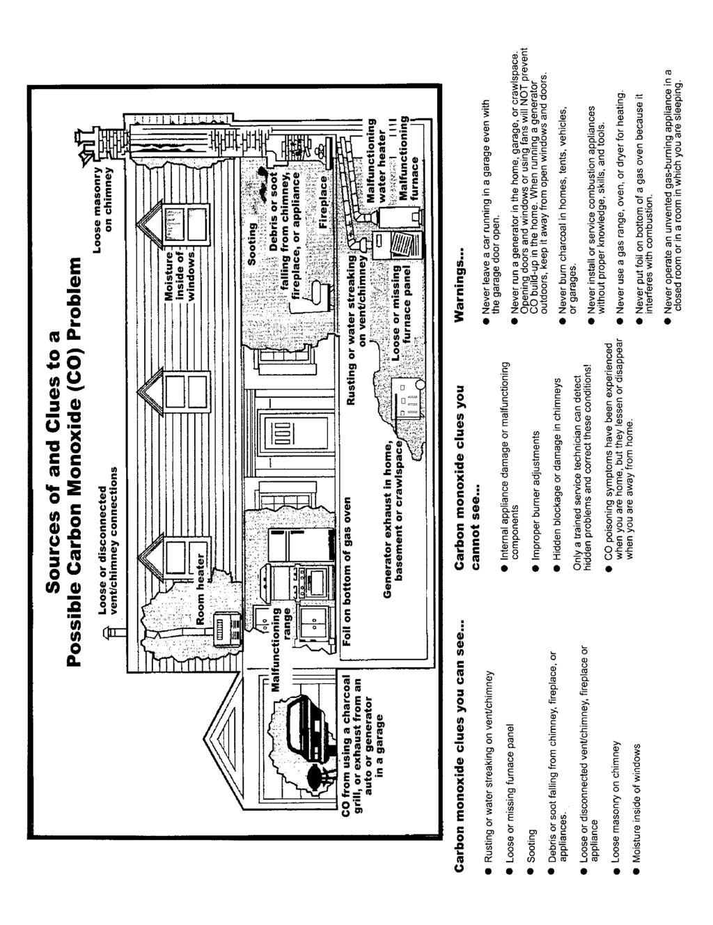
191
Alarm. A warning of danger. An indication of the existence of a condition that requires immediate action. (SIG-FUN)
") 4 of 326 11/21/2013 1:03 PM First Revision No. 161-NFPA 72-2013 [ Section No. 3.3.11 ] 3.3.11 Alarm. A warning of danger. An indication of the existence of a condition that requires immediate action. (SIG-FUN)
4 of 326 11/21/2013 1:03 PM First Revision No. 161-NFPA 72-2013 [ Section No. 3.3.11 ] 3.3.11 Alarm. A warning of danger. An indication of the existence of a condition that requires immediate action. (SIG-FUN)
Second Revision No. 104-NFPA [ Section No ] Submitter Information Verification. Committee Statement
![Second Revision No. 104-NFPA [ Section No ] Submitter Information Verification. Committee Statement](/thumbs/87/97199093.jpg "Second Revision No. 104-NFPA [ Section No ] Submitter Information Verification. Committee Statement") of 1 9/22/2014 1:38 PM Second Revision No. 104-NFPA 72-2014 [ Section No. 3.3.3 ] 3.3.3 Accessible, Readily (Readily Accessible). Capable of being reached quickly for operation, renewal, or inspections
of 1 9/22/2014 1:38 PM Second Revision No. 104-NFPA 72-2014 [ Section No. 3.3.3 ] 3.3.3 Accessible, Readily (Readily Accessible). Capable of being reached quickly for operation, renewal, or inspections
Report on First Revision November 2013 NFPA 731
 Report on First Revision November 2013 NFPA 731 731- Log #FR1 Final Action: (2.3.3) Submitter: Technical Committee Premises Security Recommendation: 2.3.3 UL Publications. Underwriters Laboratories Inc.,
NFPA 72 Code Changes vs 2013
 NFPA 72 Code Changes - 2010 vs 2013 AFAA-NE Westborough, MA February 7, 2018 Richard Roux NFPA 72 National Fire Alarm and Signaling Code Overview and 2013 Changes NFPA 72 1993 Edition Aug 20, 1993 1996
Changes in NFPA
 Changes in NFPA 72-2002 2002 Oregon Fire Code Committee November 25, 2003 Michael B. Baker, SET Automatic Fire Alarm Association MikeBaker@afaa.org 2003 Michael B. Baker 1 Table of Contents 1. Administration
STANDARDS UPDATE NOTICE (SUN) ISSUED: February 5, 2018
 ISSUED: February 5, 2018") STANDARDS UPDATE NOTICE (SUN) ISSUED: February 5, 2018 STANDARD INFORMATION Standard Number: NFPA 72 Standard Name: National Fire Alarm and Signaling Code Standard Edition and Issue Date: 2016 Edition
STANDARDS UPDATE NOTICE (SUN) ISSUED: February 5, 2018 STANDARD INFORMATION Standard Number: NFPA 72 Standard Name: National Fire Alarm and Signaling Code Standard Edition and Issue Date: 2016 Edition
 Page 1 of 40 First Correlating Revision No. 15-NFPA 72-2014 [ Global Input ] 10.5.4 Plans Examiners and Inspectors. 10.5.4.1 Fire alarm system and emergency communications system plans and specifications
1.3 REFERENCE STANDARDS
 SECTION 28 4600 FIRE DETECTION AND ALARM PART 1 -GENERAL 1.1 SECTION INCLUDES A. Fire alarm system design and installation, including all components, wiring, and conduit. B. Circuits from protected premises
Florida Building Code Chapter 9 Fire Protection Systems Advanced Course
 Florida Building Code 2010 Chapter 9 Fire Protection Systems Advanced Course 1 Introduction This course will cover specific sections of Chapter 9 that relate to fire alarm systems. While many contractors
Florida Building Code 2010
 Introduction Florida Building Code 2010 Chapter 9 Fire Protection Systems This course will cover specific sections of Chapter 9 that relate to fire alarm systems. While many contractors are familiar with
Proposed Changes to NFPA
 2017 NFPA Conference & Expo Proposed Changes to NFPA 72-2019 Presented by: Manuelita David (SIG-FUN), Jensen Hughes Warren Olsen (SIG-SSS), Fire Safety Consultants, Inc. Merton Bunker (SIG-AAC), EYP Architecture
SECTION AUTOMATIC TRANSFER SWITCHES
 PART 1 - GENERAL 1.1 DESCRIPTION SECTION 26 36 23 SPEC WRITER NOTE: Use this section only for NCA projects. Delete between //--// if not applicable to project. Also, delete any other item or paragraph
Rancho Cucamonga Fire Protection District Prevention Bureau Standard
 Rancho Cucamonga Fire Protection District Prevention Bureau Standard Title: Fire Alarm and Monitoring Systems Standard # 9-3 Effective: May 2002 Number of Pages: 7 Updated: December 2016 for consistency
SECTION FIRE ALARM SYSTEMS
 SECTION 28 3100 PART 1 -GENERAL 1.01 RELATED DOCUMENTS Drawings and general provisions of the Contract, including General and Supplementary Conditions and Division 1 Specification Sections, apply to this
Bold items are particular to the City of Euless
 EULESS FIRE DEPARTMENT FIRE MARSHAL S OFFICE INFORMATION LINE: Revised 8/2004 Fire Chief Lee Koontz Fire Marshal Paul Smith EFD-FMO 3-1 2003 International Fire & Building Code as Amended NFPA Standards
NFPA Changes
 Chapter 27, Public Fire Emergency Alarm Reporting Systems Summary. Chapter 27 was Chapter 9 in NFPA 72-2007. The word fire is replaced by the word emergency. The term public fire service communications
Moreno Valley Fire Department Fire Prevention Bureau. New and Existing Fire Alarm & Signaling Systems Guideline
 Moreno Valley Fire Department Guideline Approved and Authorized By: Adria Reinertson, Fire Marshal Issued: May 8, 2017 Alarm & Signaling Systems PURPOSE Fire alarm and signaling systems are designed to
SECTION DIGITAL, ADDRESSABLE FIRE-ALARM SYSTEM
 SECTION 283111 - DIGITAL, ADDRESSABLE FIRE-ALARM SYSTEM PART 1 - GENERAL 1.1 RELATED DOCUMENTS A. Drawings and general provisions of the Contract, including General and Supplementary Conditions and Division
2. The Group F occupancy has have an a combined occupant load of 500 or more above or below the lowest level of exit discharge.
 2. The Group F occupancy has have an a combined occupant load of 500 or more above or below the lowest level of exit discharge. Exception: Manual fire alarm boxes are not required where the building is
SANTA CLARA COUNTY Winchester Blvd., Los Gatos, CA (408) (408) (fax)
 (408) (fax)") FIRE DEPARTMENT SANTA CLARA COUNTY 14700 Winchester Blvd., Los Gatos, CA. 95032-1818 (408) 378-4010 (408) 378-9342 (fax) www.sccfd.org STANDARD DETAILS & SPECIFICATIONS Spec No C-4 Rev. Date 03/10/10 SUBJECT:
FIRE DEPARTMENT SANTA CLARA COUNTY 14700 Winchester Blvd., Los Gatos, CA. 95032-1818 (408) 378-4010 (408) 378-9342 (fax) www.sccfd.org STANDARD DETAILS & SPECIFICATIONS Spec No C-4 Rev. Date 03/10/10 SUBJECT:
26 of 128 9/23/2014 9:25 AM
 26 of 128 9/23/2014 9:25 AM Second Revision No. 105-NFPA 72-2014 [ Global Comment ] Revise the Annex F figures that include a smoke detector symbol (hexagon with a whisp of smoke) so that the new smoke
Fire Alarm System Fundamentals
 Fire Alarm System Fundamentals Mircom is the largest and oldest privately owned fire alarm and life safety manufacturer in North America and 5th largest overall with 50 years of industry experience. Mircom
FIRE & LIFE SAFTEY STANDARD
 Title: Effective Date: 01/01/14 Revised Date: 1/1/14 Code References: Title 16, Chapter 16.16 of the Roseville Municipal Code, NFPA 72 Note: This standard is a summary of Fire Department clarifications
Southaven Fire Department Fire Marshal s Office 8710 Northwest Drive Southaven, Mississippi Phone: Fax:
 Southaven Fire Department Fire Marshal s Office 8710 Northwest Drive Southaven, Mississippi 38671 Phone: 662-393-7466 Fax: 662-280-6521 Fire Alarm Maintenance Guide The City of Southaven enforces the 2012
SECTION AUTOMATIC TRANSFER SWITCHES
 PART 1 - GENERAL 1.1 DESCRIPTION SECTION 26 36 23 This section specifies the furnishing, complete installation, and connection of automatic transfer switches. 1.2 RELATED WORK A. Section 14 21 00, ELECTRIC
First Revision No. 158-NFPA [ Global Input ] Submitter Information Verification. Committee Statement
![First Revision No. 158-NFPA [ Global Input ] Submitter Information Verification. Committee Statement](/thumbs/82/85532588.jpg "First Revision No. 158-NFPA [ Global Input ] Submitter Information Verification. Committee Statement") of 326 11/21/2013 1:03 PM First Revision No. 158-NFPA 72-2013 [ Global Input ] Revise 2.3.1 to update UL 864 to "2003, revised 2012" and upate ANSI/ASME A17 to 2013. Submittal Date: Wed Sep 11 11:08:52
of 326 11/21/2013 1:03 PM First Revision No. 158-NFPA 72-2013 [ Global Input ] Revise 2.3.1 to update UL 864 to "2003, revised 2012" and upate ANSI/ASME A17 to 2013. Submittal Date: Wed Sep 11 11:08:52
Second Revision No. 1-NFPA 17A-2016 [ Section No ] Submitter Information Verification. Committee Statement. 1 of 14 6/22/2016 3:15 PM
![Second Revision No. 1-NFPA 17A-2016 [ Section No ] Submitter Information Verification. Committee Statement. 1 of 14 6/22/2016 3:15 PM](/thumbs/91/107420660.jpg "Second Revision No. 1-NFPA 17A-2016 [ Section No ] Submitter Information Verification. Committee Statement. 1 of 14 6/22/2016 3:15 PM") 1 of 14 6/22/2016 3:15 PM Second Revision No. 1-NFPA 17A-2016 [ Section No. 4.3.3 ] 4.3.3 All discharge nozzles shall be provided with caps or other suitable devices to prevent the entrance of grease vapors,
1 of 14 6/22/2016 3:15 PM Second Revision No. 1-NFPA 17A-2016 [ Section No. 4.3.3 ] 4.3.3 All discharge nozzles shall be provided with caps or other suitable devices to prevent the entrance of grease vapors,
Automatic Fire Alarm Association Webinar On Inspection, Testing, And Maintenance Of Fire Alarm Systems
 Automatic Fire Alarm Association Webinar On Inspection, Testing, And Maintenance Of Fire Alarm Systems Your Presenter: Merton Bunker, PE Inspections and tests are intended to reduce or limit: Loss of life
First Revision No. 88-NFPA [ Section No. 2.4 ] Submitter Information Verification. Committee Statement. 3 of /21/2013 1:03 PM
![First Revision No. 88-NFPA [ Section No. 2.4 ] Submitter Information Verification. Committee Statement. 3 of /21/2013 1:03 PM](/thumbs/72/67526484.jpg "First Revision No. 88-NFPA [ Section No. 2.4 ] Submitter Information Verification. Committee Statement. 3 of /21/2013 1:03 PM") 3 of 326 11/21/2013 1:03 PM First Revision No. 88-NFPA 72-2013 [ Section No. 2.4 ] 2.4 References for Extracts in Mandatory Sections. NFPA 70, National Electrical Code, 2011 2014 edition. NFPA 96, Standard
3 of 326 11/21/2013 1:03 PM First Revision No. 88-NFPA 72-2013 [ Section No. 2.4 ] 2.4 References for Extracts in Mandatory Sections. NFPA 70, National Electrical Code, 2011 2014 edition. NFPA 96, Standard
SPECIFICATION: AlarmLine TM INTELLIGENT LINEAR HEAT DETECTION
 1. GENERAL SPECIFICATION 1.1 The contractor shall provide an Intelligent AlarmLine Linear Heat Detection System to perform the following functionality: A. Fire Alarm, Supervisory and Trouble-Event Initiation
M E M O R A N D U M. NFPA Technical Committee on Building Services and Fire Protection Equipment
 M E M O R A N D U M TO: FROM: NFPA Technical Committee on Building Services and Fire Protection Equipment Linda MacKay DATE: November 10, 2009 SUBJECT: NFPA 5000 A2011 ROP Letter Ballot Final Results The
SECTION INTRUSION DETECTION
 (NOTE TO DESIGNER: These Specifications are basic minimum criteria to be met in preparing the final specifications for this section, which is the responsibility of the Designer.) SECTION 28 16 00 INTRUSION
Fire Alarm Acceptance Testing & On-Going Maintenance with The Joint Comm. Standards / Reporting. Prepared Especially for : OSFM TEC 2016
 Fire Alarm Acceptance Testing & On-Going Maintenance with The Joint Comm. Standards / Reporting Prepared Especially for : OSFM TEC 2016 Acceptance Testing 11-2008 Agenda Before you begin Completing the
M E M O R A N D U M. NFPA 5000 A2011 ROP Letter Ballot
 M E M O R A N D U M TO: FROM: NFPA Technical Committee on Building Service and Fire Protection Equipment Gregory Harrington, P.E., Staff Liaison DATE: October 1, 2009 SUBJECT: NFPA 5000 A2011 ROP Letter
CERTIFICATION BULLETIN
 File: ULC Subject C100 ULC-G.5.2 CCF7 S500F/SC2 October 28, 2014 CERTIFICATION BULLETIN 2014-07 Second Edition ULC/ORD-C100-13 Smoke Control System Equipment To: Members of the ULC Advisory Committee Members
Chapter 4: Fire Protection Systems
 Chapter 4: Fire Protection Systems Automatic Extinguishing Systems (Fire Sprinklers) One of the most important aspects of a storage warehouse inspection is ensuring that the automatic extinguishing system
Unified Fire Authority - Fire Prevention Bureau
 Unified Fire Authority - Fire Prevention Bureau FIRE ALARM AND EMERGENCY COMMUNICATION SYSTEM RECORD OF COMPLETION To be completed by the system installation contractor at the time of system acceptance
INSPECTION AND TESTING FORM
 INSPECTION AND TESTING FORM Date: Time: SERVICE ORGANIZATION Name: Address: Representative: License No.: MONITORING ENTITY Contact: Monitoring Account Ref. No.: TYPE TRANSMISSION McCulloh Multiplex Digital
CAN/ULC-S1001, INTEGRATED SYSTEMS TEST OF FIRE PROTECTION AND LIFE SAFETY SYSTEMS
 RANDAL BROWN & ASSOCIATES ENGINEERING LTD. CONSULTING ENGINEERS LIFE SAFETY & FIRE PROTECTION 105 6 LANSING SQUARE TORONTO, ONTARIO CAN/ULC-S1001, INTEGRATED SYSTEMS TEST OF FIRE PROTECTION AND LIFE SAFETY
MECKLENBURG COUNTY FIRE MARSHAL S OFFICE
 Effective Date: 11/01/02 Purpose: MECKLENBURG COUNTY To establish a set of guidelines for performance testing of all newly installed or upgraded fire alarm systems in order to ensure that all devices and
Functional Performance Test
 Fire Alarm Control Panel & Fire Alarm Annunciator Panel Notify all building occupants that testing will be conducted. Fire alarm contractor shall have personnel with 2-way radios at the fire alarm control
M E M O R A N D U M. Technical Committee on Supervising Station Fire Alarm and Signaling Systems
 National Fire Protection Association 1 Batterymarch Park, Quincy, MA 02169-7471 Phone: 617-770-3000 Fax: 617-770-0700 www.nfpa.org M E M O R A N D U M TO: FROM: Technical Committee on Supervising Station
Committee Input No NFPA [ Global Input ] Submitter Information Verification. Committee Statement. 1 of /20/ :02 AM
![Committee Input No NFPA [ Global Input ] Submitter Information Verification. Committee Statement. 1 of /20/ :02 AM](/thumbs/75/72631987.jpg "Committee Input No NFPA [ Global Input ] Submitter Information Verification. Committee Statement. 1 of /20/ :02 AM") 1 of 213 10/20/2016 11:02 AM Committee Input No. 2505-NFPA 72-2016 [ Global Input ] Change the term visible to visual where appropriate Submitter Information Verification Submitter Full Name: SIG-NAS Organization:
1 of 213 10/20/2016 11:02 AM Committee Input No. 2505-NFPA 72-2016 [ Global Input ] Change the term visible to visual where appropriate Submitter Information Verification Submitter Full Name: SIG-NAS Organization:
UNIFIED FACILITIES GUIDE SPECIFICATIONS
 USACE / NAVFAC / AFCEC / NASA UFGS-28 31 75.00 10 (November 2008) ----------------------------------- Preparing Activity: USACE Superseding UFGS-28 31 75.00 10 (April 2006) UNIFIED FACILITIES GUIDE SPECIFICATIONS
CONTENTS AUTOMATIC TRANSFER SWITCHES
 CONTENTS AUTOMATIC TRANSFER SWITCHES PART 1 GENERAL 1.1 Related Documents 1.2 Summary 1.3 References 1.4 Quality Assurance 1.5 Submittals 1.6 Delivery, Storage and Handling 1.7 Instructions And Training
Lake County / Multi-Department Storage Facility / Project / December 12, 2016 SECTION DIGITAL, ADDRESSABLE FIRE-ALARM SYSTEM
 PART 1 - GENERAL 1.1 RELATED DOCUMENTS SECTION 283111 A. Drawings and general provisions of the Contract, including General and Supplementary Conditions and Division 01 Specification Sections, apply to
Hinesville First United Methodist Church SECTION DIGITAL, ADDRESSABLE FIRE-ALARM SYSTEM
 SECTION 28 3111 DIGITAL, ADDRESSABLE FIRE-ALARM SYSTEM PART 1 - GENERAL 1.01 SUMMARY A. Section Includes: 1. Fire-alarm control unit. 2. Manual fire-alarm boxes. 3. System smoke detectors. 4. Heat detectors.
Smoke Detector Activation of any smoke detector shall start the alarm verification mode.
 Description: The purpose of the section is to provide the UMCP Design Standards for the design and implementation of Fire Alarm Systems at the UMCP campus. Related Sections: TBD Effective Date: July 10,
THE BASICS OF FIRE ALARM PLAN REVIEW
 THE BASICS OF FIRE ALARM PLAN REVIEW Art Shaw A Shaw & Associates, LLC. ashaw@arthurshaw.com 231.838.3269 Fire Protection System Plan Reviewer FP000006 NFPA Certified Plans Examiner 02-0005 NFPA Certified
National Fire Protection Association. 1 Batterymarch Park, Quincy, MA Phone: Fax:
 National Fire Protection Association 1 Batterymarch Park, Quincy, MA 02169-7471 Phone: 617-770-3000 Fax: 617-770-0700 www.nfpa.org M E M O R A N D U M TO: FROM: Technical Committee on Notification Appliances
SECTION GENERATOR PARALLELING CONTROLS
 PART 1 - GENERAL 1.1 DESCRIPTION SECTION 26 23 13 GENERATOR PARALLELING CONTROLS SPEC WRITER NOTE: Delete between // -- // if not applicable to project. Also delete any other item or paragraph not applicable
Michigan State University Construction Standards FIRE DETECTION AND ALARM PAGE
 PAGE 283100-1 SECTION 283100 - DIGITAL, ADDRESSABLE FIRE-ALARM SYSTEM PART 1 - GENERAL 1.1 RELATED DOCUMENTS A. Drawings and general provisions of the Contract, including General and Supplementary Conditions
CAN/ULC-S INTEGRATED SYSTEMS TESTING OF FIRE PROTECTION AND LIFE SAFETY SYSTEMS
 2013 Randal Brown & Associates Engineering Ltd. 1 RANDAL BROWN & ASSOCIATES ENGINEERING LTD. CONSULTING ENGINEERS LIFE SAFETY & FIRE PROTECTION 105 6 LANSING SQUARE TORONTO, ONTARIO CAN/ULC-S1001-11 INTEGRATED
Second Correlating Revision No. 21-NFPA [ Global Input ]
![Second Correlating Revision No. 21-NFPA [ Global Input ]](/thumbs/96/128256336.jpg "Second Correlating Revision No. 21-NFPA [ Global Input ]") Second Correlating Revision No. 21-NFPA 72-2017 [ Global Input ] Change "published manufacturer's instructions" and "manufacturer's instructions" to "manufacturer's published instructions" in accordance
Second Correlating Revision No. 21-NFPA 72-2017 [ Global Input ] Change "published manufacturer's instructions" and "manufacturer's instructions" to "manufacturer's published instructions" in accordance
Date Issued: December 14, 2017 Revision: 2.1
 2.1 1. Introduction A is implemented to ensure the fire safety of building occupants or a building area when the Fire Alarm System or a Fire Protection System has been temporarily disabled due to malfunction,
Kidde Nitrogen Inert Gas Clean Agent Fire Suppression System
 1. GENERAL 1.1 INTENT OF SPECIFICATIONS A. This specification details the requirements for an engineered inert gas fire suppression system Model Kidde Nitrogen. These requirements, combined with good engineering
SECTION (13730) - INTRUSION DETECTION
 - INTRUSION DETECTION") PART 1 GENERAL 1.01 SUMMARY A. Section Includes: SECTION 28 16 00 (13730) - INTRUSION DETECTION 1. Intrusion Detection Sensors 2. Signal Equipment 3. System Controls 4. Alarm Displays 5. Alarm Indicating
PART 1 GENERAL 1.01 SUMMARY A. Section Includes: SECTION 28 16 00 (13730) - INTRUSION DETECTION 1. Intrusion Detection Sensors 2. Signal Equipment 3. System Controls 4. Alarm Displays 5. Alarm Indicating
CAN/ULC-S1001, INTEGRATED SYSTEMS TESTING OF FIRE PROTECTION & LIFE SAFETY SYSTEMS Simon Crosby, LEL, CET, CFPS October 21, 2015
 CAN/ULC-S1001, INTEGRATED SYSTEMS TESTING OF FIRE PROTECTION & LIFE SAFETY SYSTEMS Simon Crosby, LEL, CET, CFPS October 21, 2015 Fire Commissioning in Canadian Codes and Standards BACKGROUND Why Commissioning?
SECTION : FIRE ALARM & DETECTION SYSTEMS
 SECTION 28 31 10: FIRE ALARM & DETECTION SYSTEMS 1. GENERAL A. This section applies to fire detection/alarm system and carbon monoxide system components and equipment installed during new construction
PWGSC Ontario MULTIPLEX FIRE ALARM SYSTEM Sect Region Project Page 1 Number R
 Region Project Page 1 PART 1 - GENERAL 1.1 REFERENCES.1 CAN/ULC-S524-2006, Standard for the Installation of Fire Alarm Systems..2 CAN/ULC-S525-2007, Audible Signal Device for Fire Alarm Systems..3 CAN/ULC-S526-2007,
Page 1 of 5 1/29/2016 4:08 PM. First Correlating Revision No. 3-NFPA [ Section No ] Submitter Information Verification
![Page 1 of 5 1/29/2016 4:08 PM. First Correlating Revision No. 3-NFPA [ Section No ] Submitter Information Verification](/thumbs/87/97398353.jpg "Page 1 of 5 1/29/2016 4:08 PM. First Correlating Revision No. 3-NFPA [ Section No ] Submitter Information Verification") First Correlating Revision No. 3-NFPA 101-2016 [ Section No. 6.1.8.1.1 ] 6.1.8.1.1* Definition One- and Two-Family Dwelling Unit. A building that contains not more than two dwelling units, with independent
First Correlating Revision No. 3-NFPA 101-2016 [ Section No. 6.1.8.1.1 ] 6.1.8.1.1* Definition One- and Two-Family Dwelling Unit. A building that contains not more than two dwelling units, with independent
CLARK COUNTY FIRE DEPARTMENT Fire Prevention Bureau
 CLARK COUNTY FIRE DEPARTMENT Fire Prevention Bureau 575 E. Flamingo Road, Las Vegas, NV 89119 (702) 455-7316 FAX (702) 455-7347 Permit Type: 105.6.54 Control Number: A.0 Effective Date: TITLE: PROPRIETARY
Architect s Project Number of 12 Fire Alarm/Smoke Detection Systems District Master Specs 2013 Edition
 PART 1 GENERAL 1.1 SECTION INCLUDES SECTION 28 31 00 FIRE ALARM AND SMOKE DETECTION SYSTEMS A. Fire alarm and smoke detection systems 1.2 REFERENCES A. NFPA 72 B. NFPA 101 1.3 REGULATORY REQUIREMENTS A.
1. Floor above/floor below notification. 2. Private alarm notification. 3. Not Used 4. Voice alarm notification. 5. Not Used.
 PART 1 GENERAL 1.01 Scope of Standard A. This Standard is intended to assure that fire alarm and signaling systems at Sam Houston State University provide the highest level of life safety possible. This
NEC Requirements for Standby Power Systems. New England Building Officials Education Association Annual Conference October 5, 2015
 NEC Requirements for Standby Power Systems New England Building Officials Education Association Annual Conference October 5, 2015 Emergency & Standby Power Systems Alternative power sources are utilized
Table OUT OF SERVICE. Building Fire Video 1/15/ Inspection, testing and maintenance. Standards Further Referenced by FCNYS
 901.6 Inspection, testing and maintenance. Fire detection, alarm and extinguishing systems shall be maintained in an operative condition at all times, and shall be replaced or repaired where defective.
First Revision No NFPA [ Global Input ] Submitter Information Verification. Committee Statement 10/20/ :03 AM
![First Revision No NFPA [ Global Input ] Submitter Information Verification. Committee Statement 10/20/ :03 AM](/thumbs/87/97044121.jpg "First Revision No NFPA [ Global Input ] Submitter Information Verification. Committee Statement 10/20/ :03 AM") of 496 10/20/2016 11:03 AM First Revision No. 2501-NFPA 72-2016 [ Global Input ] Any place in the body of Chapter 18 or its annex that the value 0.0375 lumens/ft 2 is used the metric equivalent shall be
of 496 10/20/2016 11:03 AM First Revision No. 2501-NFPA 72-2016 [ Global Input ] Any place in the body of Chapter 18 or its annex that the value 0.0375 lumens/ft 2 is used the metric equivalent shall be
SAF-BCF SECOND REVISIONS WITH STATEMENTS
 Page 196 of 331 32.2.1.3 ] Second Revision No. 153-NFPA 101-2013 [ New Section after 32.2.1.4 Multiple-Level Buildings. For purposes of applying requirements of this chapter that utilize the term level
CAN/ULC S Integrated Systems Testing of Fire Protection and Life Safety Systems and Fire Protection Commissioning
 CAN/ULC S1001-11 Integrated Systems Testing of Fire Protection and Life Safety Systems and Fire Protection Commissioning Presentation To: Canadian Fire Alarm Association (CFAA) National Capital Region
Control Panel. 1.0 GENERAL SCOPE OF WORK Introduction... 2
 Architectural & Engineering Specifications Control Panel 1.0 GENERAL... 2 1.1 SCOPE OF WORK... 2 1.1.1 Introduction... 2 1.2 GENERAL CONDITIONS... 2 1.2.1 After-Sales Support... 2 1.2.2 Quality assurance...
SECTION FIRE ALARM AND SMOKE DETECTION SYSTEMS
 PART 1 GENERAL 1.1 SECTION INCLUDES A. Fire alarm and smoke detection systems 1.2 REFERENCES A. NFPA 72 B. NFPA 101 1.3 REGULATORY REQUIREMENTS A. System: UL listed B. Conform to requirements of NFPA 101
UNIFIED FACILITIES GUIDE SPECIFICATIONS
 USACE / NAVFAC / AFCEC / NASA UFGS-28 31 02.00 20 (February 2010) ----------------------------------- Preparing Activity: NAVFAC Superseding UFGS-28 31 02.00 20 (November 2009) UNIFIED FACILITIES GUIDE
Fire Alarm, Water Flow Alarm & Signaling Systems
 Orange County Fire Authority Community Risk Reduction 1 Fire Authority Road, Building A, Irvine, CA 92602 www.ocfa.org 714-573-6100 Fire Alarm, Water Flow Alarm & Signaling Systems Guideline D-03 Serving
Questions/Comments for Richard Roux from Webinar on 7/11/13
 Questions/Comments for Richard Roux from Webinar on 7/11/13 Below are the questions and comments from the July 11, 2013 webinar 2013 NFPA 72: Design and Installation Requirements for Mass Notification
OJD ITB No Attachment E Duress Alarm Equipment Specifications
 Duress Alarm Equipment Specifications PART 1 GENERAL 1.1 SECTION INCLUDES A. Duress devices. B. Alarm control panel. C. Signaling devices. 1.2 REFERENCE STANDARDS A. NFPA 70 - National Electrical Code;
Type of Fire Alarm Control Panel: System is: Existing OR New If new, provide Electrical Permit Number:
 DATE OF SUBMISSION TO: Department of Licenses and Inspections Commercial and Industrial Fire Inspection Unit 990 Spring Garden Street, 3 rd Floor, Philadelphia, PA 19123 AP# CITY OF PHILADELPHIA FIRE ALARM
Balloting Version First Draft NFPA 101 Life Safety Code Proposed 2015 Edition
 Copyright National Fire Protection Association 2013. All rights reserved. This copy is solely for your personal, noncommercial use in connection with participation in the NFPA Standards Development Process.
Fort Rouge Leisure Centre Section HVAC Upgrades Phase 2 Page 1 of 5 Bid Opportunity No March 2013 FIRE ALARM SYSTEMS
 HVAC Upgrades Phase 2 Page 1 of 5 Part 1 General 1.1 SUMMARY.1 Section Includes:.1 Materials and installation for fire alarm systems upgrades..2 Audible signal devices..3 End-of-line devices..4 Sustainable
SECTION 907 FIRE ALARM AND DETECTION SYSTEMS
 SECTION 907 FIRE ALARM AND DETECTION SYSTEMS 907.1 General. This section covers the application, installation, performance and maintenance of fire alarm systems and their components in new and existing
CERTIFICATION BULLETIN
 File: ULC-S527-11 ULC-G5.2 June 1, 2012 CERTIFICATION BULLETIN 2012-04 Effective Date Announcement CAN/ULC-S527-11, 3 rd Edition of the Standard for Control Unit for Fire Alarm Systems To: Subscribers
NFPA Siemens Industry, Inc. All rights reserved. usa.siemens.com/infrastructure-cities
 Fire Alarm and Signaling Code Overview NFPA 72-2010 usa.siemens.com/infrastructure-cities Siemens Building Technologies, Inc. is a Registered Provider with The American Institute of Architects Continuing
DIGITAL, ADDRESSABLE FIRE ALARM SYSTEM
 SECTION 283111 - DIGITAL, ADDRESSABLE FIRE-ALARM SYSTEM PART 1 - GENERAL 1.1 RELATED DOCUMENTS A. Drawings and general provisions of the Contract, including General and Supplementary Conditions and Division
SECTION FIRE ALARM
 SECTION 16740 PART 1 - GENERAL 1.1 RELATED DOCUMENTS A. Drawings and general provisions of the Contract, including General and Supplementary Conditions and Division 1 Specification Sections, apply to this
WORKING DRAFT OF COMMITTEE MEETING OUTPUT
 WORKING DRAFT OF COMMITTEE MEETING OUTPUT CONTENT NOT FINAL SUBJECT TO REVISION PRIOR TO LETTER BALLOT AND PUBLICATION OF FIRST DRAFT REPORT Document: NFPA 110 (EPS-AAA) Revision Cycle: A2018 Meeting Date(s):
COMMERCIAL (IBC) FIRE ALARM SUBMITTAL GUIDE
 FIRE ALARM SUBMITTAL GUIDE") COMMERCIAL (IBC) FIRE ALARM SUBMITTAL GUIDE SUPERVISION OF AUTOMATIC FIRE SPRINKLER SYSTEMS SUPERVISION OF ALTERNATIVE AUTOMATIC FIRE-EXTINGUISHING SYSTEMS FIRE ALARM AND DETECTION SYSTEMS The Fire Alarm
COMMERCIAL (IBC) FIRE ALARM SUBMITTAL GUIDE SUPERVISION OF AUTOMATIC FIRE SPRINKLER SYSTEMS SUPERVISION OF ALTERNATIVE AUTOMATIC FIRE-EXTINGUISHING SYSTEMS FIRE ALARM AND DETECTION SYSTEMS The Fire Alarm
Fire Alarm System Inspection and Testing Report
 Fire Alarm System and ing Report Date of : Time of : 1. PROPERTY INFORMATION: Name of Property: Address: of property: Occupancy Type: Name of property representative: Address: Phone: Fax: E-mail: Local
First Revision No. 339-NFPA [ Section No. 2.2 ]
![First Revision No. 339-NFPA [ Section No. 2.2 ]](/thumbs/73/69137555.jpg "First Revision No. 339-NFPA [ Section No. 2.2 ]") 8 of 326 11/21/2013 1:03 PM First Revision No. 339-NFPA 72-2013 [ Section No. 2.2 ] 2.2 NFPA Publications. National Fire Protection Association, 1 Batterymarch Park, Quincy, MA 02169-7471. NFPA 10, Standard
8 of 326 11/21/2013 1:03 PM First Revision No. 339-NFPA 72-2013 [ Section No. 2.2 ] 2.2 NFPA Publications. National Fire Protection Association, 1 Batterymarch Park, Quincy, MA 02169-7471. NFPA 10, Standard
The 2013 National Fire Alarm and Signaling Code
 ARE YOU A MEMBER OF AFAA? WHY SHOULD YOU BE A MEMBER BECAUSE YOUR BUSINESS IS IMPORTANT James Mongeau The 2013 National Fire Alarm and Signaling Code 1 NFPA 72 Organization Be*er organiza2on Easier to
El Reno Fire Department Fire Alarm Plan Review Worksheet
 El Reno Fire Department Fire Alarm Plan Review Worksheet This Fire Alarm Plan Review Checklist is provided as a guide to assist with your Fire Alarm Plan Review Submittal requirements. Please contact us
First Revision No. 82-NFPA [ Section No ] Submitter Information Verification. Committee Statement. 2 of /21/2013 1:03 PM
![First Revision No. 82-NFPA [ Section No ] Submitter Information Verification. Committee Statement. 2 of /21/2013 1:03 PM](/thumbs/87/96930323.jpg "First Revision No. 82-NFPA [ Section No ] Submitter Information Verification. Committee Statement. 2 of /21/2013 1:03 PM") 2 of 326 11/21/2013 1:03 PM First Revision No. 82-NFPA 72-2013 [ Section No. 2.3.4 ] 2.3.4 ISO Publications. International Organization for Standardization, 1, ch. de la Voie-Creuse, Case postale 56, CH-1211
2 of 326 11/21/2013 1:03 PM First Revision No. 82-NFPA 72-2013 [ Section No. 2.3.4 ] 2.3.4 ISO Publications. International Organization for Standardization, 1, ch. de la Voie-Creuse, Case postale 56, CH-1211
SECTION FIRE ALARM STANDARDS REVISED CONSTRUCTION STANDARD
 PART 1 - GENERAL PURPOSE This Standard is intended to assure that fire detection/alarm systems at The University of Texas at Austin provide the highest level of fire safety possible. SCOPE This standard
MNEC NFPA 72 WHITE PAPER
 MNEC NFPA 72 WHITE PAPER In 2010, the National Fire Protection Assocation (NFPA), significantly changed their code # 72 (National Fire Alarm Code) and has forever improved the importance of communicating
FIRE ALARM PRE-INSPECTION CHECKLIST 1. REFER TO CHAPTER 10 OF CURRENT STATE ADOPTED NFPA 72, FOR INSPECTION, TESTING AND MAINTENANCE PROCEDURES.
 FIRE ALARM PRE-INSPECTION CHECKLIST Prepared by: Representing: Date: 1. REFER TO CHAPTER 10 OF CURRENT STATE ADOPTED NFPA 72, FOR INSPECTION, TESTING AND MAINTENANCE PROCEDURES. 2. PROVIDE DRAWINGS IN
Standard for the Installation of Carbon Monoxide (CO) Detection and Warning Equipment
 Detection and Warning Equipment") NFPA 720 2015 Summary Standard for the Installation of Carbon Monoxide (CO) Detection and Warning Equipment TM, 7Oct14 CODE: Title, Standard, not Code Consistent with recent trend at NFPA, this document
NFPA 720 2015 Summary Standard for the Installation of Carbon Monoxide (CO) Detection and Warning Equipment TM, 7Oct14 CODE: Title, Standard, not Code Consistent with recent trend at NFPA, this document
NFPA Changes
 Chapter 21, Emergency Control Functions and Interfaces Summary. Chapter 21 is new. These requirements were formerly found in Chapter 6, Protected Premises Fire Alarm Systems. The term fire safety function
Report on First Revision June 2014 NFPA 5000
 5000- Log #12 BLD-BSF Final Action: (55.2 (New) ) NOTE: This proposal appeared as Comment 5000-168 (Log #86) which was held from the A11 ROC on Proposal 5000-239. Submitter: Technical Correlating Committee
SECTION CLEAN AGENT FIRE SUPPRESSION SYSTEMS
 SECTION 21 22 00 CLEAN AGENT FIRE SUPPRESSION SYSTEMS PART 1 - GENERAL 1.1 DESCRIPTION SPEC WRITER NOTE: Delete between // --- // if not applicable to the project. Also delete any other item or paragraph
Fire Pump Supervision - Part 2 by Dean K. Wilson, P.E.
 Fire Alarm Notebook by Dean K. Wilson. P.E. Page 1 Fire Pump Supervision - Part 2 by Dean K. Wilson, P.E. Question: As the Authority Having Jurisdiction in my suburban community, I have largely had to
National Fire Protection Association. 1 Batterymarch Park, Quincy, MA Phone: Fax:
 National Fire Protection Association 1 Batterymarch Park, Quincy, MA 02169-7471 Phone: 617-770-3000 Fax: 617-770-0700 www.nfpa.org M E M O R A N D U M TO: FROM: Technical Committee on Testing and Maintenance
The Standard for Remote Supervising Station (SRSS-01) 2007
 2007") The Standard for Remote Supervising Station (SRSS-01) 2007 Electronic Security Association 2300 Valley View Lane, Suite 230 Irving, TX 75062 888-447-1689 1 The Standard for Remote Supervising Station (SRSS-01)
The Standard for Remote Supervising Station (SRSS-01) 2007 Electronic Security Association 2300 Valley View Lane, Suite 230 Irving, TX 75062 888-447-1689 1 The Standard for Remote Supervising Station (SRSS-01)