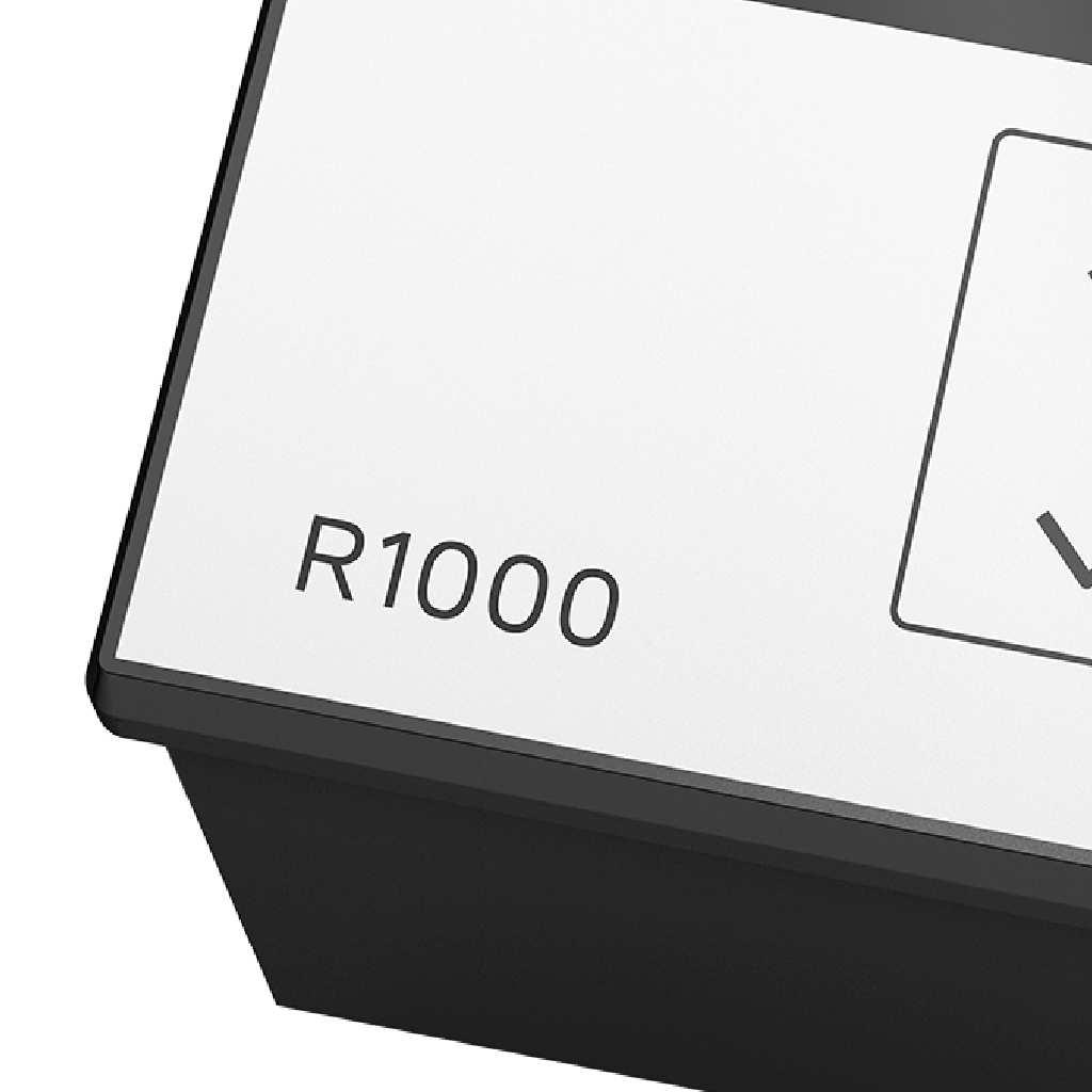
R1000 / R1040 / R1080
|
|
|
- Philip Mathews
- 5 years ago
- Views:
Transcription


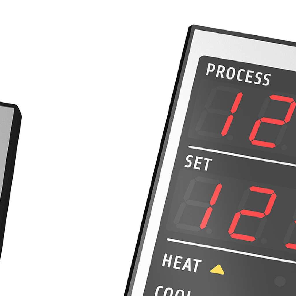
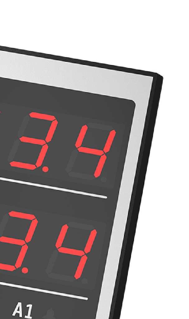


1 R1000 / R1040 / R Zone Temperature Controller: Heat-only Heating-off-cooling Three-point stepping DIN-Format: 96mm x 96mm / 48mm x 96mm / 96mm x 48mm Description and operating manual ELOTECH Industrieelektronik GmbH Verbindungsstraße 27 D HILDEN FON / FAX / info@elotech.de Manual: R10x X_EN Release: 1.03 Elotech GmbH age 1 / 20
2 1 Contents 1 Contents General Information Installation Instructions Type Code Connection Diagram Display and Keyboard Operating Levels arameter descriptions Device configuration level Alarm configuration level arameter level Operating Level Error Messages Technical Data Notes...20 Manual: R10x X_EN Release: 1.03 Elotech GmbH age 2 / 20

3 2 General Information Used symbols: Messages shown by the controller display < > Symbolizes the value of the factory adjustment of the respective parameter. >ID< This parameter is available in ID controller mode only. >DS< This parameter is available in Three-oint Stepping mode only. 3 Installation Instructions Make sure that the device is used for the intended purpose only. This controller is designed for installation in control panels. rotect the device against impermissible humidity and contamination. Ambient temperature must not exceed 50 C (122 F). Electrical connections must be made according to valid regulations and by properly qualified personnel. If using thermocouple sensors, compensation lines have to be connected directly to the controller terminals. Sensors may be connected only in compliance with the programmed range. Sensor cables and signal lines (e.g. logic or linear voltage outputs) must be laid separately from control lines and mains voltage supply cables (power cables). It is not permitted to connect the grounds of the sensor-inputs and logic-outputs with each other! Separate installation of controller and inductive loads is recommended. Interference from contactor coils must be suppressed by connecting adapted RC-combinations parallel to the coils. Control circuits (e.g. for contactors) should not be connected to the mains power supply terminals of the controller. The configuration parameters are generally to be selected first. Disclaimer of Liability We have checked the contents of this document for conformity with the hardware and software described. Nevertheless, we are unable to preclude the possibility of deviations so that we are unable to assume warranty for full compliance. However, the information given in the publication is reviewed regularly. Necessary amendments are incorporated in the following editions. We would be pleased to receive any improvement suggestions which you may have. The information contained herein is subject to change without notice. Electronic scrap and components are subject to special treatment and must be disposed of by authorized companies. Manual: R10x X_EN Release: 1.03 Elotech GmbH age 3 / 20
4 4 Type Code R10x x 1 5 ower supply 230 VAC ower supply 24 VDC 00 Sensor: T100, Ni120, Thermocouple J, K, L, N, S 20 2/3-point controller / 3-point-stepping-controller R1000 Format 96mm x 96mm R1040 Format 48mm x 96mm R1080 Format 96mm x 48mm Manual: R10x X_EN Release: 1.03 Elotech GmbH age 4 / 20
5 5 Connection Diagram L / DC - ower Supply N / DC + OUT A Relay OUT B Relay +Uout OUT L Logic ϑ ϑ TC T100 3-wire T100 2-wire Manual: R10x X_EN Release: 1.03 Elotech GmbH age 5 / 20
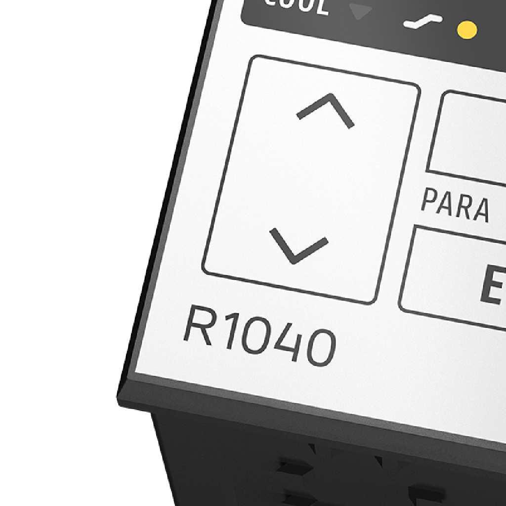
 Adjustment of chosen parameter (e.g. setpoint) to higher or lower values.")

6 6 Display and Keyboard LED H: Heating active LED A1: Alarm 1 LED C: Cooling active LED Setpoint ramp active LED A2: Alarm 2 Key functions: arameter key (parameter preselection) Adjustment of chosen parameter (e.g. setpoint) to higher or lower values. Short operation: single-step adjustment Longer operation: quick-scanning When the parameter adjustments have been altered but not entered, the display will flash bright/dark. Confirmation and storage of the preselected values. The display will show a light chain as a control of this function. Manual: R10x X_EN Release: 1.03 Elotech GmbH age 6 / 20
7 6.1 Operating Levels The operation of the controller is divided into 4 levels. After power up the device will be in the operating level. ress and E ress and E for 1 sec ress and E for 1 sec Operating level Setpoint (set) arameter level (output ratio) Y Alarm configuration level rf.a1 Device configuration level Conf AL1_ H LY re.a1 Out.L AL2 OFSt ti.a EL.01 Return to operating level: ress E for 1 sec or wait for a period of 30 sec Operating level: rocess- and Setpoint value will be displayed simultaneously. In the operating level the setpoint and other parameters can be adjusted by pressing the U"-/ DOWN"-keys. Every adjustment has to be confirmed by pressing the E -key. All parameters in the operating level can, in succession, be displayed by pressing the -key. The three other levels can be reached by simultaneously pressing the "- and E"-keys. By pressing for a longer time (approx. 1 s) it can be switched to the next level. The parameters are selected and set according to the descriptions of the operating level. After either pressing the E -key for approx. 1 second, or waiting for a period of approx. 30 seconds, the unit will automatically return to the operating level. Control parameter level: In the control parameter level the parameter values are adjusted to suit each individual process. Alarm configuration level: In the alarm configuration level the parameters are adjusted for the alarm monitoring. Device configuration level: In the configuration level the basic configurations of the controller are set. These adjustments have to be carried out first of all when starting the controller for the first time. Manual: R10x X_EN Release: 1.03 Elotech GmbH age 7 / 20
8 7 arameter descriptions 7.1 Device configuration level Controller configuration Assignment of the signal for the output "Logic" Assignment of the signal for the output "Relay A" Assignment of the signal for the output "Relay B" When changing the controller configuration, the settings of the outputs will be changed, too. They can be altered manually afterwards. 2-point controller "heating-off" < > Output settings: = ; = ; = 2-point controller "cooling-off Output settings: = ; = ; = 2-point controller cooling non-linear. Cooling action with non-linear cooling response curve (e.g. for vapour cooling) Output settings: = ; = ; = 3-point-controller heating-off-cooling Output settings: = ; = ; = 3-point-controller heating-off-cooling. Cooling action with non-linear cooling response curve (e.g. for vapour cooling) Output settings: = ; = ; = Three-point-stepping controller Heating corresponds to OEN, Cooling corresponds to CLOSE Output settings: = ; = ; = Output is turned off Output represents the heating -signal< > Output represents the cooling -signal Output represents the alarm 1-signal Output represents the alarm 2-signal Output is turned off Output represents the heating -signal< > Output represents the cooling -signal Output represents the alarm 1-signal Output represents the alarm 2-signal Output is turned off Output represents the heating -signal< > Output represents the cooling -signal Output represents the alarm 1-signal Output represents the alarm 2-signal Manual: R10x X_EN Release: 1.03 Elotech GmbH age 8 / 20
9 Sensor selection Lower setpoint limitation Higher setpoint limitation t C < > t F t C t F Ni C Ni F Thermocouple (TC) Fe-CuNi(L) C Thermocouple (TC) Fe-CuNi(L) F Thermocouple (TC) Fe-CuNi(L) C Thermocouple (TC) Fe-CuNi(L) F Thermocouple (TC) Fe-CuNi(J) C Thermocouple (TC) Fe-CuNi(J) F Thermocouple (TC) NiCr-Ni(K) C Thermocouple (TC) NiCr-Ni(K) F Thermocouple (TC) trh-t(s) C Thermocouple (TC) trh-t(s) F Thermocouple (TC) NiCrSi-NiSi(N) C Thermocouple (TC) NiCrSi-NiSi(N) F Lowest adjustable setpoint value < = 0 C> programming range: bottom range Highest adjustable setpoint value < = 400 C> programming range: top range Ramp function: A programmed ramp is always activated when the setpoint is changed or when the mains supply is switched on. The ramp starts at the actual process value and ends at the preselected setpoint. Rising ramp Falling ramp < >; 0,1 100,0 C/min or F/min < >; 0,1 100,0 C/min or F/min Manual: R10x X_EN Release: 1.03 Elotech GmbH age 9 / 20
10 Softstart Function in General: If the softstart function is selected, it has to be made sure that the bistable voltage (logic) output is activated. Otherwise the relays will be damaged. During the softstart the controllers heating output response is limited to a preselected ratio, in order to achieve a slow drying of high performance heat cartridges. This results in a slower, more regular heating period. Simultaneously the output clock frequency is quadrupled. Once the process value reaches the softstart setpoint, it remains stable at this value for the preselected duration time. At the end of this period the process value rises to the valid setpoint. If the softstart is active, the controller's autotune function cannot operate ( ). If a setpoint ramp has been programmed, the softstart has priority, and the ramp will become active after the softstart has been completed. The parameters for the softstart function are only available if the parameter (xp) is programmed to a value > 0,1% (parameter level). The softstart only works if the actual process value is lower than the softstart setpoint at the time the controller is turned on. Temperature Setpoint Softstart Setpoint SST-Output-Ratio SST-Duration-Time t Softstart Softstart output ratio Y Softstart setpoint Softstart duration time Softstart function is not active. < > The other softstart parameters are not displayed. Softstart function is active. Range: % < = 30> Range:....< = 100> Range:, min. < = 2.0> Manual: R10x X_EN Release: 1.03 Elotech GmbH age 10 / 20
11 Manual mode Automatic Mode Manual Mode Controller mode < > In the case of a sensor break the last valid output ratio is maintained. An H is then displayed as the first digit in the setpoint display, followed by the valid output ratio. Like the setpoint, the output ratio can be changed manually. Under the following circumstances, the output ratio will be 0%: - if the output ratio at the time of the sensor break was 100%. - if a setpoint ramp is active. - if the control deviation was more than 0,25% of the total range at the time of sensor break. - if the roportional-band () = off. - if the softstart was active at the time of the sensor break. A few seconds after the sensor break has been rectified, the controller returns to automatic operation and calculates the required output ratio. An additional signal can be issued in the event of sensor break, if the alarm contacts are programmed accordingly. The controller now operates only as an actuator. The control function (ID) is inactive. ROCESS: Actual process value is shown. Display of setpoint: First an H, then the actual adjustable output ratio. Negative value: cooling, positive value: heating Like the setpoint, the output ratio can be changed manually. Configuration Sensor break Behaviour of the relays in case of sensor break >DS< Filter time Adjustment lock Luminance or Outputs: OEN = off CLOSE = off< > Outputs: OEN = on CLOSE = off Outputs: OEN = off CLOSE = off Range: ; s < = OFF> If the process is not stable, filter time can be set to reduce oscillations of the process display. It has no influence on the controlling process. no adjustment lock < > parameter and configuration levels locked all parameters apart from S1 locked (not S1) all parameters locked Adjustment of the luminance of the 7-segment-display. Adjustment range : 0...6< > Device code and version Manual: R10x X_EN Release: 1.03 Elotech GmbH age 11 / 20
12 7.2 Alarm configuration level General alarm information (example alarm 1): Description Based to setpoint Absolut Alarm configuration = = Range of / Whole measuring range Switch point Setpoint + Alarm value Singlesided alarm "top": (over temperature alarm) The temperature has to be higher to activate the alarm. setpoint over temperature over temperature The under temperature alarm is not active: = 0 0 Singlesided alarm "bottom": (under temperature alarm) The temperature has to be lower to activate the alarm. setpoint under temperature under temperature The over temperature alarm is not active: = 0 0 Both-sided alarm: (limit-alarm) The temperature has to be outside the selected range. Both alarms ( and ) have to be set. setpoint 0 over temperature under temperature 0 over temperature under temperature The parameter for the s (,,, ) are located in the operating level. lease note: In case of sensor error the alarms react in the same way as range override. The alarm contacts therefore do not offer protection against all types of plant breakdown. We recommend the use of a second, independent monitoring unit. Manual: R10x X_EN Release: 1.03 Elotech GmbH age 12 / 20
13 Alarm 1 configuration (reference. alarm 1) relay action for alarm 1 Display of front LED at alarm 1 Start up suppression alarm 1 delay time alarm 1 absolute < > based on setpoint relay is turned off when alarm 1 is active relay is turned on when alarm 1 is active < > LED is turned off when alarm 1 is active LED is turned on when alarm 1 is active < > Start up suppression deactivated < > Start up suppression activated The temperature has to enter the OK range once. Thereafter the alarm triggers when the temperature reaches the alarm limits., s < = OFF> Alarm 2 configuration reference. alarm 2 relay action for alarm 2 Display of front LED at alarm 2 Start up suppression alarm 2 delay time alarm 2 absolute < > based on setpoint relay is turned off when alarm 2 is active relay is turned on when alarm 2 is active < > LED is turned off when alarm 2 is active LED is turned on when alarm 2 is active < > Start up suppression deactivated < > Start up suppression activated The temperature has to enter the OK range once. Thereafter the alarm triggers when the temperature reaches the alarm limits., s < = OFF> Manual: R10x X_EN Release: 1.03 Elotech GmbH age 13 / 20
14 7.3 arameter level valid output ratio Output ratio limit heating Output ratio limit cooling >ID< >ID< >ID< 0 100% The output ratio shows the momentary calculated ratio. It cannot be altered. The display is in per cent of the installed performance capability for heating or cooling. Output ratio for cooling is shown as a negative value %< > The limitation of the output ratio is only necessary if the heating energy supply is grossly overdimensioned compared to the power required. Under normal conditions a limitation is not necessary (setting = 100%). The limitation becomes effective when the controller's calculated output ratio is greater than the maximum permissible (limited) ratio. Warning! The output ratio limitation does not work during autotune %< > same as output ratio limit heating Adjustment of the control parameters: As standard the controller operates in D/I control mode, i. e. controlling without deviation and with practically no overshoot during start-up. The control action can be altered in its structure by adjusting the following values to the parameters: a. no control action, on-off b. -action c. D-action d. Ie. D/I prop. band () heating >ID< rate (D) heating reset(i) heating cycle time heating >ID< >ID< setting = setting D and I = setting I = setting D = modified ID-mode (set:, D, I) According to the configuration, certain parameters are not visible. ; % < =3,0> If = (control action: on-off, without feedback) Next visible parameter: s < = 30> s < = 150> s < =15.0> The switching frequency of the actuator can be determined by adjusting the cycle time. In this time interval the controller switches on and off once. Voltage outputs for SSRs cycle time: 0, s Optimal value for fast control loops: 0,8 s >ID< Relay outputs: cycle time: > 15 s The cycle time should be adjusted to a time as long as possible to minimize the wear of the relay contacts. Manual: R10x X_EN Release: 1.03 Elotech GmbH age 14 / 20
15 xp, prop.-band () >DS< ; % < = 10.0> Motor actuating time (d) >DS< s < = 40> reset time (I) >DS< min < = 3.0> / switch sensitivity heating This parameter is only available if: = ; 0.1< > 80.0 switch sensitivity: setpoint process value Manual: R10x X_EN Release: 1.03 Elotech GmbH age 15 / 20
16 Switch point difference heating and cooling ; 0.1< > 20.0 If the controller is in heating mode, the actual process value has to rise by the adjusted value above the setpoint before the cooling mode will become active. By this the switching frequency between the heating and cooling outputs can be reduced. Simultaneous activation of heating and cooling outputs is not possible. prop. band () cooling rate (D) cooling reset(i) cooling cycle time cooling ; % < =3,0> If = (control action: on-off, without feedback) next parameter:. ; s < = 30> ; s < = 150> s < = 15.0> The switching frequency of the actuator can be determined by adjusting the cycle time. In this time interval the controller switches on and off once. Voltage outputs for SSRs cycle time: s Optimal value for fast control loops: 0.8 s Relay outputs: cycle time: > 15 s The cycle time should be adjusted to a time as long as possible to minimize the wear of the relay contacts. switch sensitivity cooling This parameter is only available if: = ; 0.1< > 80.0 C switch sensitivity: setpoint process value Manual: R10x X_EN Release: 1.03 Elotech GmbH age 16 / 20
17 Autotune: The tuning algorithm determines the characteristic values within the controlled process and calculates the valid feedback parameters (, D, I) and the cycle time (= 0.3 x D) of a D/I-controller for a wide section of the range. The autotune mode is activated during start-up shortly before the setpoint is reached. If activated after the setpoint has already been reached, the temperature will first drop by approx. 5 % of the measuring range in order to detect the exact amplification of the process. The tuning algorithm can be activated at any time by selecting = and pressing the E -key. After having calculated the correct feedback parameters, the controller will lead the process value to the setpoint. Selecting = will stop the autotune function. Zone display: During self tuning is shown in the display, alternating with the setpoint value. Conditions for starting the Autotune algorithm: - The setpoint must add up to at least 5 % of the measuring range. - The sensor must not have a failure. - The softstart function must not be active. X X Set self tune start OT on self tune during start-up t OT on self tune, after the setpoint has already been reached t autotune process value offset autotune / self tuning out of action< > autotune / self tuning active ( one time) Autotune starts every time the controller is turned on, if the difference between setpoint and actual process value is more than 7 % of the measuring range < > 1000 C/ F This parameter serves to correct the input signal, e.g. for: - the correction of a gradient between the measuring point and the sensor tip - the line resistance balancing of 2-line RTD (t100) sensors - correction of the control deviation when using - or D-action If for example the offset value is set to +5 C, the real temperature measured by the sensor (when process is balanced) is 5 C less than the setpoint and the displayed actual process value. Make sure that the corrected temperature process value does not leave the selected measuring range. Manual: R10x X_EN Release: 1.03 Elotech GmbH age 17 / 20
18 7.4 Operating Level The function and configuration of the alarms is described in the chapter alarm configuration level. Within the operating level only the s can be set. Alarm 1: under temperature Alarm 1: over temperature Alarm 2: under temperature Alarm 2: over temperature Alarm reference Adjustment range: = absolute = based to setpoint = absolute = based to setpoint = absolute = based to setpoint = absolute = based to setpoint < >; Alarm active if the actual process value is lower than the < > K; Alarm active if the actual process value is lower than (Setpoint + ) < >; Alarm active if the actual process value is higher than the < >; K Alarm active if the actual process value is higher than (Setpoint + ) < >; Alarm active if the actual process value is lower than the < > K Alarm active if the actual process value is lower than (Setpoint + ) < >; Alarm active if the actual process value is higher than the < >; K Alarm active if the actual process value is higher than (Setpoint + ) 8 Error Messages Error Message Cause ossible remedy Lower setpoint limit has been reached Reduce limit, if need be Upper setpoint limit has been reached Increase limit, if need be arameter has been locked Top range end has been exceeded, sensor defect Bottom range end has been exceeded, sensor defect Self tuning error System error Unlock, if need be Device configuration level: Check sensor and cable Check sensor and cable Check process value offset Quit error message by pressing the key E. Check the self tuning conditions and restart. Quit error message by pressing the key E. Check all parameters. If the error message continues, please send the controller back to the manufacturer. Manual: R10x X_EN Release: 1.03 Elotech GmbH age 18 / 20
19 9 Technical Data Input T100 (RTD) Input Thermocouple Output logic Outputs relay 7-Segment-Display: Data protection 2- or 3-wire connection possible Built-in protection against sensor break and short circuit Sensor current: < 0,5 ma Calibration accuracy: < 0,2 % Linear error: < 0,2 % Influence of the ambient temperature: < 0,01 % / K Built-in internal compensation point and protection against sensor break and incorrect polarity. Re-calibration not required for a line resistance of up to 50 Ohm. Calibration accuracy: < 0,25 % Linear error: < 0,2 % Influence of the ambient temperature: < 0,01 % / K Bist. voltage signal, 0/18 V DC, max. 10 ma, short-circuit proof Relay, max. 250 VAC, max. 2 A (resistive load) For control loops requiring a high switching frequency of the control output it is recommended to use the logic output controlling a SSR. 4 digits, rocess: 10 mm red, Set: 10 mm red EAROM CE-mark Tested according to 2004/108/EG; EN Electrical safety: EN ower supply Connections ermissible operating conditions Casing Weight Depends on the version of the device: V AC, +/-10 %, Hz; approx. 3VA - 24 V DC, +/-25 %, approx. 3W Spring-cage connector, rotection mode I 20 (DIN 40050), Insulation class I Conductor cross section terminals 1-7: 0,2-2,5mm² Conductor cross section terminals 10-15: 0,2-1,5mm² Operating temperature: Storage temperature: Climate class: Material: rotection mode: Case: Format R1000: Format R1040: Subject to technical improvements C / F C / F KWF DIN 40040; equivalent to annual average max. 75 % rel. humidity, no condensation Noryl, self-extinguishing, non-drip, UL 94-V1 I 20 (DIN 40050), I 50 front side DIN 43700, installation depth approx. 60 mm 96 x 96 mm anel cutout: 92 +0,5 mm x 92 +0,5 mm 48 x 96 mm anel cutout: 45 +0,6 mm x 92 +0,8 mm Approx. 350 g depending on the version of the device Manual: R10x X_EN Release: 1.03 Elotech GmbH age 19 / 20
20 10 Notes Manual: R10x X_EN Release: 1.03 Elotech GmbH age 20 / 20
DESCRIPTION AND OPERATING MANUAL
 R 2000-421 / 422 / 426... R 2000-621 / 622 / 626... R 2000-821 / 822 / 826... 4 - Zones heat-only Temperature Controller 6 - Zones heat-only Temperature Controller 8 - Zones heat-only Temperature Controller
Interchangeable thermistor (THE types) Output Contact E5CS-R1KJX-F E5CS-R1PX-F E5CS-R1GX-F Voltage E5CS-Q1KJX-F E5CS-Q1PX-F E5CS-Q1GX-F
 Output Contact E5CS-R1KJX-F E5CS-R1PX-F E5CS-R1GX-F Voltage E5CS-Q1KJX-F E5CS-Q1PX-F E5CS-Q1GX-F") Temperature Controller 1/16 DIN Sized Controller Offers Selectable Control, Alarm Modes Accurate to ±0.5% of full scale Multiple temperature scale ranges allow flexibility to match application Field-selectable
Temperature Controller 1/16 DIN Sized Controller Offers Selectable Control, Alarm Modes Accurate to ±0.5% of full scale Multiple temperature scale ranges allow flexibility to match application Field-selectable
VERTEX VT10 SERIES PID OPERATION MANUAL MICROPROCESSOR BASED PID CONTROLLER
 1 VERTEX VT10 SERIES PID OPERATION MANUAL MICROPROCESSOR BASED PID CONTROLLER 1. INTRODUCTION This manual contains information for the installation and operation and tuning of our Vertex VT10 series self-tuning
Electronic Temperature Controller 70304,
 Electronic Temperature Controller 70304, 70304.2 Instruction Manual Version 1.00.01 List of content 1 General information... 4 2 Declaration of conformity... 4 3 Safety instructions... 5 4 Warranty...
Tempco Part Number PCT30006 Temperature Control Enclosure with Relay Output for Tote Tank Heating Applications
 Instruction Manual Tempco Part Number PCT30006 Temperature Control Enclosure with Relay Output for Tote Tank Heating Applications Manual PCT30006, Revision 9/20/2016 The PCT30006 control enclosure incorporates
02/11/2015
 MIC48 With RS 485 link Part number 89422418 Heating and / or cooling function 2 independent alarms Load break detection 2 setpoint which can be selected remotely Manual / automatic power adjustment RS
Page 1 Operating Instructions OI 6496 / 6596
 age 1 Microprocessor - based controller µcelsitron baelz 6496 / baelz 6596 Continuous controller Industrial controller with continuous output Easy operation Two adjustable setpoints User - defined operating
Tempco PCT-3000 Series Temperature Control Console with Relay Output for Heating or Cooling Applications
 Instruction Manual Tempco PCT-3000 Series Temperature Control Console with Relay Output for Heating or Cooling Applications Manual PCT-3000 Revision 9/2014 The PCT-3000 series control console incorporates
TC515 and TC600 Installation Manual. a Winters company
 THERMOLINE TEMPERATURE CONTROLLERS TC515 and TC600 Installation Manual a Winters company Guarantee 12 months Congratulations on the purchase of this new product. Special care with the design, workmanship
02/11/2015
 CTH 46 - CTD 43 / 46 CTD 46 Part number 89422108 CTH 46 Heating / cooling function Measurement and setpoint display CTD 43 Heating or cooling function Measurement display Measurement deviation display-setpoint
ECL Comfort 110, application 116
 Operating Guide ECL Comfort 110, application 116 (valid as of software version 1.08) English version www.danfoss.com How to navigate? Adjust temperatures and values. Switch between menu lines. Select /
Universal controller for panel mounting Models CS6S, CS6H, CS6L
 Accessories Universal controller for panel mounting Models CS6S, CS6H, CS6L WIKA data sheet AC 85.08 Applications Plant and industrial furnace construction Process engineering Plastics technology and processing
F4 Process Controller Installation and Operation Guide
 F4 Process Controller Installation and Operation Guide 1.Introduction 1.1.Highlight Features Space saving, only 55mm panel depth required Higher sampling rate (1mS) results in better control performance
Safety Temperature Limiter STL 50 Certified to DIN EN (replaces DIN 3440)
") Safety Temperature Limiter STL 50 Certified to DIN EN 14597 (replaces DIN 3440) Features M For use as: STB Protection - temperature limiter ASTB Exhaust gas - protection - temperature limiter STW Protection
Safety Temperature Limiter STL 50 Certified to DIN EN 14597 (replaces DIN 3440) Features M For use as: STB Protection - temperature limiter ASTB Exhaust gas - protection - temperature limiter STW Protection
EKC 347 Liquid Level Controller REFRIGERATION AND AIR CONDITIONING. Manual
 EKC 347 Liquid Level Controller REFRIGERATION AND AIR CONDITIONING Manual Contents Introduction...3 Valve compatibility...3 Features...3 Application examples...3 Ordering...3 Operating the EKC 347...4-5
Weather compensated flow temperature control of heating and boiler systems
 Instructions ECL Comfort 110 Application 130 Weather compensated flow temperature control of heating and boiler systems User guide, Installation & Maintenance DH-SMT/DK VI.KT.G3.02 Danfoss 06/2008 How
OVEN INDUSTRIES, INC.
 OVEN INDUSTRIES, INC. OPERATING MANUAL Model 5C7-252 TEMPERATURE CONTROLLER With PLC Inputs Introduction Thank you for purchasing our controller. The Model 5C7-252 is an exceptionally versatile unit and
I/A Series 716C 1/16 DIN Temperature Controller
 Product Specifications I/A Series 716C 1/16 DIN Temperature Controller PSS 2C-1B5 A The Foxboro 716C is a powerful compact, 1/16 DIN, microprocessor-based temperature controller that offers a variety of
ECL Comfort 110, application 130
 Operating Guide ECL Comfort 110, application 130 (valid as of software version 1.08) English version www.danfoss.com How to navigate? Adjust temperatures and values. Switch between menu lines. Select /
C62. ECL Comfort. User's Guide. Installer's Guide. ECL Comfort C62. User's Guide. Installer's Guide *VIKME102* *087R8091* *087R8091* *VIKME102*
 User's Guide VI.KM.E1.02 2005.09 C62 *VIKME102* *087R8091* www.danfoss.com ECL Comfort User's Guide ECL Comfort Installer's Guide www.danfoss.com *087R8091* *VIKME102* Double mixing controller C62 VI.KM.E1.02
ST Wiring diagram. Product description. Standard temperature controller. Order number
 ST64-31.10 Standard temperature controller Order number 900197.007 Old Id.Nr.: 386169 Wiring diagram Product description The controller ST64-31.10 was developed for simple thermostatic controls. The round
Nov 08 PRODUCT SPECIFICATION SHEET
 Honeywell UDC1200 and UDC1700 MICRO-PRO SERIES UNIVERSAL DIGITAL CONTROLLERS 51-52-03-35 Nov 08 PRODUCT SPECIFICATION SHEET OVERVIEW The UDC1200 & UDC1700 are microprocessor-based 1/16 DIN and 1/8 DIN
C66. ECL Comfort. User's Guide. Installer's Guide. ECL Comfort C66. User's Guide. Installer's Guide. *vi7cc502* *087R8069* *087R8069* *vi7cc502*
 User's Guide VI.7C.C5.02 2005.09 C66 *vi7cc502* *087R8069* www.danfoss.com ECL Comfort User's Guide ECL Comfort Installer's Guide www.danfoss.com *087R8069* *vi7cc502* Mixing controller with PI controlled
SCHMIDT LED Measured Value Display MD Instructions for Use
 SCHMIDT LED Measured Value Display MD 10.010 Instructions for Use Table of Contents 1 Important Information... 3 2 Application range... 4 3 Mounting instructions... 4 4 Electrical connection... 6 5 Signalizations...
ESM x72 DIN Size Temperature Controller. Universal Input Temperature Controller
 ESM- 7720 72x72 DIN Size Temperature Controller ESM-7720 72 x 72 DIN Size Universal Input Temperature Controller - 4 digits process(v) and 4 digits process set value(sv) display - Universal process input
ESM x48 DIN 1/16 Temperature Controller. ESM x 48 DIN 1/16 Temperature Controller with Universal Input
 ESM- 4420 48x48 DIN 1/16 Temperature Controller ESM-4420 48 x 48 DIN 1/16 Temperature Controller with Universal Input - 4 digits process(v) and 4 digits process set value(sv) display - Universal process
Specification , July 2015
 Technical Information PrecisionLine Controllers EDC21 / EDC22 / EDC23 EASYSET DIGITAL CONTROLLERS Specification 51-52-3-48, July 215 Introduction The EDC21, EDC22 and EDC23 controllers provide precise
C37. ECL Comfort. User's Guide. Installer's Guide. ECL Comfort C37. User's Guide. Installer's Guide *VI7CE602* *087R8070* *087R8070* *VI7CE602*
 User's Guide VI.7C.E6.02 2005.09 C37 *VI7CE602* *087R8070* www.danfoss.com ECL Comfort User's Guide ECL Comfort Installer's Guide www.danfoss.com *087R8070* *VI7CE602* Mixing controller with ON / OFF controlled
ESM x 72 DIN Size Universal Input Temperature Controller
 ESM-7720 72 x 72 DIN Size Universal Input Temperature Controller - 4 digits process(v) and 4 digits process set value(sv) display - Universal process input (TC, RTD ) - Configurable ON/OFF,, I, D and ID
Model 96VTR ¼ DIN Process Controller
 99 Washington Street Melrose, MA 02176 Phone 781-665-1400 Toll Free 1-800-517-8431 Visit us at www.testequipmentdepot.com Back to the Extech 96VTR Product Info Page INSTRUCTION MANUAL Model 96VTR ¼ DIN
UDC100 Universal Digital Controller Specifications
 UDC100 Universal Digital Controller Specifications 51-52-03-29 November 1999 Overview The UDC100 Universal Digital Controller is a microprocessor-based 1/4 DIN low cost temperature controller. It combines
UDC1000 and UDC1500 MICRO-PRO SERIES UNIVERSAL DIGITAL CONTROLLERS
 UDC1000 and UDC1500 MICRO-PRO SERIES UNIVERSAL DIGITAL CONTROLLERS EN0I-6041 4/01 PRODUCT SPECIFICATION SHEET OVERVIEW The UDC1000 and UDC1500 are microprocessor-based 1/16 DIN and 1/8 DIN controllers
HPS-C-MULTI 6. Hotrunner Controllers. Operating manual. Valid for item numbers:
 Valid for item numbers: HPS-C-MULTI 6: 69010.306 (6-zone) 69010.312 (12-zone) 69010.324 (24-zone) 69010.336 (36-zone) HPS-C-MULTI 6 Hotrunner Controllers Operating manual HPS-C-MULTI 6 with WIRE TEST (WT):
Temperature Controllers
 Model TEC-4100 1/4 DIN Model TEC-4100 1/4 DIN Temperature Controller Ordering Code: Power Input BOX 1 4 = 90-250 VAC 5 = 11-26 VAC / VDC TEC-4100- Configurable for 4 Programmable Outputs and NEMA 4X/IP65
Serie Rugghölzli 2 CH Busslingen. Tel. +41 (0) Fax +41 (0)
 Fax +41 (0)") Serie 5000 Tel. +1 (0)5 222 Fax +1 (0)5 222 12 PRODUCT INTRODUCTI PRODUCT INTRODUCTI 5 Series programmable temperature controller is FineTek's mid-range series of controllers. It uses a 12bit analog /
Serie 5000 Tel. +1 (0)5 222 Fax +1 (0)5 222 12 PRODUCT INTRODUCTI PRODUCT INTRODUCTI 5 Series programmable temperature controller is FineTek's mid-range series of controllers. It uses a 12bit analog /
99 Washington Street Melrose, MA Phone Toll Free Visit us at
 99 Washington Street Melrose, MA 02176 Phone 781-665-1400 Toll Free 1-800-517-8431 Visit us at www.testequipmentdepot.com Back to the Extech 48VTR Product Info Page Instruction Manual English / Español
Jetstream Series HPLC - PELTIER COLUMN-THERMOSTATS 1. GENERALITIES
 Generalities HPLC - PELTIER COLUMN-THERMOSTATS GENERALITIES This manual has been updated to the actual standard. It now covers all the features of the actual Jetstream series models. All rights concerning
ST710-KHJV.03. Wiring diagram. Product description. Temperature controller. Order number
 ST71-KHJV.3 Temperature controller Order number 921.8 Wiring diagram Product description The switching outputs of the thermal controller can be programmed as -two-point controller with alarm -three-point
Table of Contents SECTION PAGE SECTION 1 INTRODUCTION Description Features Models... SECTION 2 RS-232 COMMUNICATIONS...
 SECTION Table of Contents SECTION 1 INTRODUCTION...................... 1.1 Description............................... 1.2 Features................................. 1.3 Models..................................
UDC 700 Universal Digital Controllers and Indicator Specifications
 UDC 700 Universal Digital Controllers and Indicator Specifications 51-52-03-28 August 2002 Overview The UDC 700 is a 1/32 DIN (49 x 25 mm) controller which combines a high degree of technology and quality
Connections, displays and operating elements C D E G H. Installing the control unit
 1 2 3 GB Control unit 0-10 V REG-K/3-gang with manual mode Operating instructions Art. no. MTN646991 ¼ DANGER Risk of fatal injury from electrical current. All work on the device should only be carried
HTC-915 Installation & operating manual
 HTC-915 Installation & operating manual 915 SERIES PE N L To external alarm annunciater / DCS or PLC input Max 3A 250V CT input To external alarm annunciater / DCS or PLC input Max 3A 250V 21 20 19 18
SD Series Users' Manual
 SD Series Users' Manual 1 Model Types 1 23456 SD-96 M R R R N 1Dimension 2Input 3 4 5 6Communication 96 : W96*H96 M : Multi R:Relay Output R:Relay Output R:Relay Output N:No Communication 94 : W96*H48
SYL-1512A PID TEMPEARATURE CONTROLLER INSTRUCTION MANUAL Version 2.1
 SYL-1512A PID TEMPEARATURE CONTROLLER INSTRUCTION MANUAL Version 2.1 Jun. 2007 Auber Instruments, 730 Culworth, Alpharetta, GA 30022 www.auberins.com e-mail: auberins@gmail.com Tel: 404-291-6298 WARNING
VERTEX F4 Instruction Manual
 VERTEX F4 Instruction Manual 02/2018 The VERTEX F4 controller 1/16 DIN is our LOW COST yet HIGH SPEC controller. Configurable on input between various thermocouples from the keypad by the user or when
INSTRUCTIONS FOR THE 8500 SERIES MICROPROCESSOR BASED TEMPERATURE CONTROL
 INSTRUCTIONS FOR THE 8500 SERIES MICROPROCESSOR BASED TEMPERATURE CONTROL December, 1998 Page 1 949-1275-1 TABLE OF CONTENTS MODEL IDENTIFICATION... 4 INSTALLATION... 4 WIRING... 5 FRONT PANEL KEY FUNCTIONS...
MR4PMUHV Electronic. Temperature/Defrost Control with Relay Pack
 Master Catalog 125 Temperature Controls Section A Product/Technical Bulletin Issue Date 1098 MR4PMUHV Electronic Temperature/Defrost Control with Relay Pack The MR series temperature controls are designed
Table of Contents SECTION PAGE
 Table of Contents SECTION PAGE SECTION 1 INTRODUCTION................... 1.1 Description.............................. 1.2 Features................................ 1.3 Models.................................
Operating instructions
 MA00929301 09/2015 Operating instructions ED10429002 ESYLUX GmbH An der Strusbek 40 22926 Ahrensburg Germany info@esylux.com www.esylux.com 1 Table of contents 1 Using the manual 8 2 Safety instructions
CM 16. Temperature controllers with compact dimensions. Manual 42/61-72 EN Rev. 01
 CM 16 Temperature controllers with compact dimensions Manual 42/61-72 EN Rev. 01 Table of contents Page Remarks... 2 Installation and commissioning 1. Identifying the instrument... 3 2. Selecting installation
Series Temperature Controller Instruction Sheet
 Series Temperature Controller Instruction Sheet Thank you very much for purchasing DELTA A Series. Please read this instruction sheet before using your A series to ensure proper operation and please keep
Table of Contents. T538 Instruction Manual Rev # 6 June R6T538 June rtf E L Switchgear and Control Inc
 Table of Contents Introduction...2 Mounting...2 Dimensions...2 Controls...3 Screen Displays...3 Screen Messages...4 Light Test...5 Control Power...5 Wiring...5 Inputs...7 Outputs...7 Programming...8 Technical
INSTRUCTION MANUAL T-154. DOSSENA s.n.c. Via Federico Barbarossa s/n Cavenago di Adda tel Fax:
 INSTRUCTION MANUAL T-154 DOSSENA s.n.c. Via Federico Barbarossa s/n 26824 Cavenago di Adda tel. +39 0371 44971 Fax: +39 0371 70202 http://www.dossena.it R.0 02/12/01 protection relays BT MT 220VAC-24VAC
MR3CCUHV Temperature/Defrost Control
 Master Catalog 125 Temperature Controls Section A Product/Technical Bulletin Issue Date 0401 MR3CCUHV Temperature/Defrost Control The MR3CCUHV Temperature/Defrost Control is designed to control the temperature
MODEL EM-10 ELECTRIC BOILER CONTROL OPERATION AND INSTRUCTION MANUAL
 MODEL EM-10 ELECTRIC BOILER CONTROL OPERATION AND INSTRUCTION MANUAL The EM-10 Boiler Temperature Control (BTC) is an efficient boiler operator with a digital LCD display with backlight, a boiler pump
Inductive Conductivity Measurement. Simultaneous display of conductivity/ resistance/salinity and temperature; large measurement symbol.
 Process Analysis Systems Chem Energy Pharm Food Water Stratos Eco 2405 CondI Inductive Conductivity Measurement Simultaneous display of conductivity/ resistance/salinity and temperature; large measurement
SA100. General Description. Features. Temperature Controller SA100. Corresponding to Various Applications. Simple Mounting on DIN Rail
 Temperature Controller General Description The is a socket mounting type temperature controller and is available for mounting inside the panel or by easily mounting on DI rail. The has features such as
GMH 285 / GMH 285-BNC
 GMH 285 GMH 285-BNC H69.0.01.6C-02 Operating Manual Pt1000 Precision Thermometer For exchangeable probes, with alarm as of version V1.0 GMH 285 / GMH 285-BNC GMH-GREISINGER GMH-GREISINGER WEEE-Reg.-Nr.
CM 8. Temperature controllers with compact dimensions. Manual 42/61-71 EN Rev. 01
 CM 8 Temperature controllers with compact dimensions Manual 42/61-71 EN Rev. 01 Table of contents Page Remarks... 2 Installation and commissioning 1. Identifying the instrument... 3 2. Selecting installation
B-40/B-41 Modulating Temperature Controller
 INSTALLATION & OPERATING INSTRUCTIONS B-40/B-41 Modulating Temperature Controller For Raytherm Boilers & Water Heaters H2 514-4001 WH2 2100-4001 Catalog No. 5000.70 Effective: 12-21-11 Replaces: NEW P/N
Micro-controller X C C1 C2 AL1 AL2 AL3. Model: PXR4/5/9. Operation Manual SEL PXR. ECNO:406e
 C C1 C2 AL1 AL2 AL3 Micro-controller X Model: PXR4/5/9 PXR SEL Operation Manual ECNO:46e Table of Contents Part Names and Functions... 6 Operations... 7 2-1 Parameter list... 7 2-2 Basic operations...
SA200. General Description. Features. Temperature Controller SA200. Self-Tuning Algorithm. Close Vertical or Horizontal Mounting
 Temperature Controller General Description The is a high performance 3 nd DI controller that has been specifically designed for applications where panel space is critical. Though small in size, this controller
AutomationDirect. PC35 Configuration Sheet
 Part#: Project: AutomationDirect PC35 Configuration Sheet Name: Date: Main Setpoint (): Cycle 5 INPUT DEFAULT CODE/VALUE Type 1 Dppo OFF Unit [ Offs 0 Spll -150 Spkl 1370 Rsll -150 Rskl 1370 Cycle 6 I/O
E21.X.01.6C-05 Operating Manual EB2000 MC page 1. Operating manual EB2000 MC. for up to 9 sensor modules. Version 3.0
 E21.X.01.6C-05 Operating Manual EB2000 MC page 1 Operating manual EB2000 MC EASYBUS-display with MIN-/MAX-alarm for up to 9 sensor modules Version 3.0 Pursuant to EN 50 081-1 and EN 50 082-2 for unlimited
TYPE CM-2201 NELSON SINGLE POINT CIRCUIT MANAGEMENT SYSTEM
 2 Line, 16 Characters/row LCD Display Temperature Input Range -50 C to +500 C -58 F to + 932 F Enclosure NEMA Type 4X Current Rating 30A max (resistive load only) Ambient Temperature -40 C to + 40 C -40
eed quality electronic design USER s MANUAL
 eed quality electronic design www.dem-it.com eed www.qeed.it info@qeed.it ANALOG SIGNAL DISPLAY Q-DISP-T USER s MANUAL The displays Q-DISP-T, prepared for mounting on the back panel, 96x48mm, will allow
Series Digital Controller Instruction Sheet
 216/3/11 Series Digital Controller Instruction Sheet Thank you very much for purchasing DELTA DTC Series Temperature Controller. Please read this instruction sheet before using your DTC series to ensure
ABB MEASUREMENT & ANALYTICS DATA SHEET. C50 1/16 DIN controller / alarm unit
 ABB MEASUREMENT & ANALYTICS DATA SHEET C50 1/16 DIN controller / alarm unit 2 C50 1/16 DI N CON TROLL ER / AL ARM U NIT DS/C 50-E N RE V. M Measurement made easy C50 the 1/16 DIN controller to suit your
LINEAR HEAT DETECTION CABLE DURÁN-SAFE
 LINEAR HEAT DETECTION CABLE DURÁN-SAFE Installation & User Manual 2018 DURAN ELECTRONICA S.L. - All rights reserved www.duranelectronica.com I-manSAFECABLE-v05 TABLE OF CONTENTS Pages 1. INTRODUCTION...
AutomationDirect PM24. Microprocessor - Based Process/Temperature Limit Controller. Operator s Manual. Technical Support.
 AutomationDirect 1/16 DIN Series Technical Support We strive to make our manuals the best in the industry. We rely on your feedback to let us know if we are reaching our goal. If you cannot find the solution
Max HT Air Heater FOR SAFETY & LONG HEATER LIFE, CAREFULLY READ THIS MANUAL BEFORE USE.
 Max HT Air Heater FOR SAFETY & LONG HEATER LIFE, CAREFULLY READ THIS MANUAL BEFORE USE. Safety SHOCK HAZARD! Only qualified individuals should install this heater and related controls. Follow all applicable
Installation and operation manual DPC200 - DIFFERENTIAL PRESSURE CONTROLLER. Low pressure with PI-control-mode
 Installation and operation manual DPC200 - DIFFERENTIAL PRESSURE CONTROLLER Low pressure with PI-control-mode Manufacturer: Phone: Fax: E-Mail: Website: Issue: Doc.-no.: Arthur Grillo GmbH Am Sandbach
Module Features are-configurable, no module jumpers to set
 December 2011 PACSystems* RX3i Isolated Thermocouple Input Module, 6 Channels, IC695ALG306 Isolated Thermocouple Input Module, 12 Channels, IC695ALG312 Isolated Thermocouple Input module IC695ALG306 provides
MODEL SF-10 CONTROL OPERATION AND INSTRUCTION MANUAL
 MODEL SF-10 CONTROL OPERATION AND INSTRUCTION MANUAL The SF-10 Temperature Control () is an efficient boiler operator with a digital LCD display with backlight, a boiler pump output, and an alarm. The
VT4810 SINGLE / DUAL ZONE CONTROLLER INSTALLATION MANUAL
 Thermocouple Type BS4937 (IEC584-3): Outer / + / - BS1843 (Old UK Standard) Outer / + / - US Outer / + / - J : Iron / Copper-Nickel Black / Black / White Black / Yellow / Blue Black / White / Red VT4810
TEMPERATURE CONTROLLER
 TEMPERATURE CONTROLLER E5CX(-H) DIN-sized super-compact (48 x 48-mm) Temperature Controller Featuring Advanced PID Control Advanced PID control with two degrees of freedom improves stability and response
DE20 INSTRUCTION MANUAL
 DE20 INSTRUCTION MANUAL Now UL Listed! SET POINT DE20 SET YOUR DISTRIBUTOR: Chemical Distributors, Inc. 80 Metcalfe Street - Buffalo, NY 14206 Phone: 800-777-2436 716-856-2300 Fax: 716-856-7115 sales@cdibuffalo.com
MICRO CONTROLLER S Z SERIES
 Instruction Manual MICRO CONTROLLER S Z SERIES TYPE: PYW 4 5 7 9 Fuji Electric Co.,Ltd. INP-TN1PYWf-E INTRODUCTION You are now the owner of Fuji's digital Temperature Controller. Before using, be sure
AL3000 SERIES 100MM CHART MULTI-POINT TYPE HYBRID RECORDER
 AL3000 SERIES 100MM CHART MULTI-POINT TYPE HYBRID RECORDER MODEL AL3 7 5 - AL3000 series conforming to CE, UL and CSA are 100mm multi-point type hybrid recorders with a simultaneous display of multi-channel
Important Supplementary Manual to the main Ezeio manual. 5. Section 2a: Introducing the 2400 input and output expansion field stations.
 1 P age Ezeio v9-120317 Eze Cloud Based Monitoring Systems. Created by Intech Instruments Ltd December 2014 Important Supplementary Manual to the main Ezeio manual. Ezeio Controller and the 2400-A16 input
122.1mm. Relay Open in alarm N/O. snubber. line. Com N/C. Closed in alarm. snubber line 2A Com snubber Open in alarm ALARM 1 N/O. Relay.
 ALARM 1 INPUT ALARM 2 RESET 92 and 92i Installation and Operating Instructions This controller meets the requirements of the European Directives on Safety and EMC. It is the responsibility of the installer
Autoclave Operations Manual
 UNIVERSITY OF ILLINOIS AT URBANA/CHAMPAIGN - COMPOSITES MANUFACTURING LAB Autoclave Operations Manual Version 1 Written by KRH 2/21/2011 Contents ACCS... 4 Alarms... 7 Main Display Tabs... 7 Process Control
2CDC D Product manual ABB i-bus KNX LGS/A 1.2 Air Quality Sensor with RTC
 2CDC 508 179 D0201 24.11.2017 Product manual ABB i-bus KNX LGS/A 1.2 Air Quality Sensor with RTC Table of contents Table of contents 1 s on the instruction manual... 12 2 Safety... 13 2.1 Information and
Installation Manual Tracker 221
 Installation Manual Tracker 221 KSR KUEBLER AG Im Kohlstatterfeld 17 D-69439 Zwingenberg / Germany www.ksr-kuebler.com Contents About this Installation Manual...4 Description Tracker 220-series...4 Installing
Control solutions Biofloor
 TEF234 Electronic room thermostat with display 230V & 24V COMAP proposes a new control system for heating and cooling underfloor. Consisting of a 6 or 10- channels controller (MCF234), analogic (TAF234)
HTC-915-CONT. Heat-Trace Control system
 Heat-Trace Control system Product overview The Raychem HTC-915 system is a compact, full-featured microprocessor-based single-point heat-trace controller. The HTC-915-CONT provides control and monitoring
- Data Brochure Universal Reset Module 423
 - Data Brochure Universal Reset Module 423 D 423 08/07 1 Information Brochure Choose controls to match application Application Brochure Design your mechanical applications 2 3 Rough-in Wiring Rough-in
ABOUT THIS DOCUMENT AND THE DOCUMENT STRUCTURE WE USE
 ABOUT THIS DOCUMENT AND THE DOCUMENT STRUCTURE WE USE isocket Smart Relay is a complex Smart House system which is installed in the fuse cabinet (electric cabinet) in the house. We therefore assume that
Safety. DANGER Indicates potentially fatal situations. WARNING Indicates possible danger to life and limb.
 Edition 06.14 GB Operating and installation instructions Lago FB digital remote control Translation from the German 2014 Elster GmbH Safety Please read and keep in a safe place Please read through these
- Data Brochure Universal Reset Module 422
 - Data Brochure Universal Reset Module 422 D 422 08/07 1 Information Brochure Choose controls to match application Application Brochure Design your mechanical applications 2 3 Rough-in Wiring Rough-in
Rooftop Thermostat Controller Specification and Installation Instructions. Model TRT2422
 ºF / º C Rooftop Thermostat Controller Model TRT2422 Description The TRT2422 is a combination controller and thermostat with a built-in scheduler, which is designed for simple and accurate control of single
RVL471 Heating and Domestic Hot Water Controller Basic Documentation
 RVL471 Heating and Domestic Hot Water Controller Basic Documentation Edition: 2.2 Controller series: C CE1P2524E 23.10.2002 Siemens Building Technologies HVAC Products 2/118 HVAC Products 23.10.2002 Contents
DIGITAL METERS Large Display Temperature Meters Instruction Manual
 DIGITAL METERS Large Display Temperature Meters PD755 PD756 PD757 Handles Thermocouple & RTD Inputs with Simplicity J, K, T, E, R, & S Thermocouples 100 Ω Platinum RTD (0.00385 or 0.00392 curve) Large
PF1000 CONTROLLER. for the. Heateflex Corporation 405 E. Santa Clara St. Arcadia, CA TEL: (626) ; FAX: (626)
 ; FAX: (626)") PF1000 CONTROLLER for the AQUARIUS I/II DEIONIZED WATER HEATING SYSTEM Heateflex Corporation 405 E. Santa Clara St. TEL: (626)599-8566; FAX: (626)599-9567 Rev. 07 10/19/10, (PF1000) 1 2 TABLE OF CONTENTS
PF1000 CONTROLLER for the AQUARIUS I/II DEIONIZED WATER HEATING SYSTEM Heateflex Corporation 405 E. Santa Clara St. TEL: (626)599-8566; FAX: (626)599-9567 Rev. 07 10/19/10, (PF1000) 1 2 TABLE OF CONTENTS
SITRANS T. SITRANS T Explosion protected temperature sensor. General information. Marking of the degree of protection. Range of uses.
 General information 1 Marking of the degree of protection 2 SITRANS T SITRANS T Explosion protected temperature sensor Operating Instructions Range of uses 3 Installation 4 Assembly and disassembly 5 Commissioning
ER52 - Evaporator Controller
 ER52 - Evaporator Controller Electronic Refrigeration Line Product Bulletin Devices are standalone digital controller for static or ventilated refrigeration units working at positive temperatures. They
TEMPERATURE CONTROL MODULE MODEL R3-TC2
 INSTRUCTION MANUAL R3-TC2 TEMPERATURE CONTROL MODULE MODEL R3-TC2 CONTENTS BEFORE USE... 2 POINTS OF CAUTION... 2 COMPONENT IDENTIFICATION... 2 INSTALLATION... 2 EXTERNAL DIMENSIONS unit: mm (inch)...
English. Operating manual. Safety temperature limiter STL50 Approved in accordance with: DIN EN (replacing DIN 3440) SIL 2
 SIL 2") English Operating manual Safety temperature limiter STL50 Approved in accordance with: DIN EN 14597 (replacing DIN 3440) SIL 2 Company / brands of GHM www.ghm-messtechnik.de Save for later reference. GHM
English Operating manual Safety temperature limiter STL50 Approved in accordance with: DIN EN 14597 (replacing DIN 3440) SIL 2 Company / brands of GHM www.ghm-messtechnik.de Save for later reference. GHM
QAF64.2-J QAF64.6-J. Frost detector. for use on the air side
 s Frost detector for use on the air side QAF64.2-J QAF64.6-J With active capillary tube sensing element for acquiring the lowest temperature within a range of 0 15 C With startup function Operating voltage
7EF/7HF/7EC/7ES Temperature Controllers
 7EF/7HF/7E/7ES Temperature ontrollers Dual 4 Digit LED Display Universal Input (6 T/, RTD, mv, V, ma) Autotuning NEMA 4X 100 to 240 Vac Switching Power Supply Algorithms for Heat or Heat/ool ontrol 2 Independent