Pre-Installation Requirements:
|
|
|
- Georgina Wheeler
- 5 years ago
- Views:
Transcription


 to the")


1 AlphaRefuge 2100 Series (V3) Area of Refuge and Rescue Assistance system Installation, Use and Wiring Instructions Pre-Installation Requirements: 120V Power Determine Communication: 1. Dedicated analog phone line from POTS, PBX, or Central Office. 2. VoIP - requires use of Alpha Model ABL-VOIP to connect Master to VoIP phone system. 3. Internal Intercom (no offsite calling) - requires Alpha Model 2100-LINESIM. Twisted, shielded 22 or 24 AWG wire cabling to connect each Refuge Call Box (RCB) to the Refuge Command Center (RCC) Use 24V 18/2 wire for powering the Emergency Phones from the 24VDC Power Supply. NOTE: Terminals and markings shown in this manual may not be in the order in which they appear on the actual equipment. When installing, observe all national and local electrical and building codes. Copyright , Alpha Communications, All Rights Reserved. AWD265 Rev. 1 (02/2018)

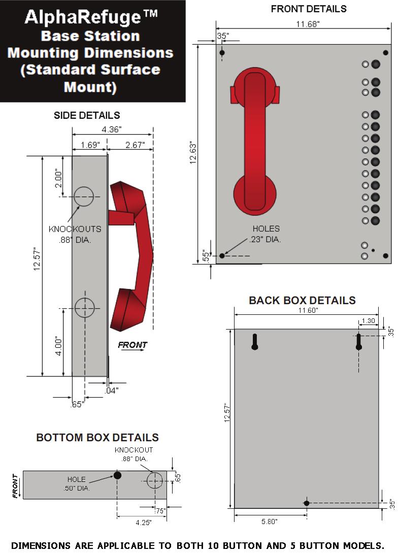
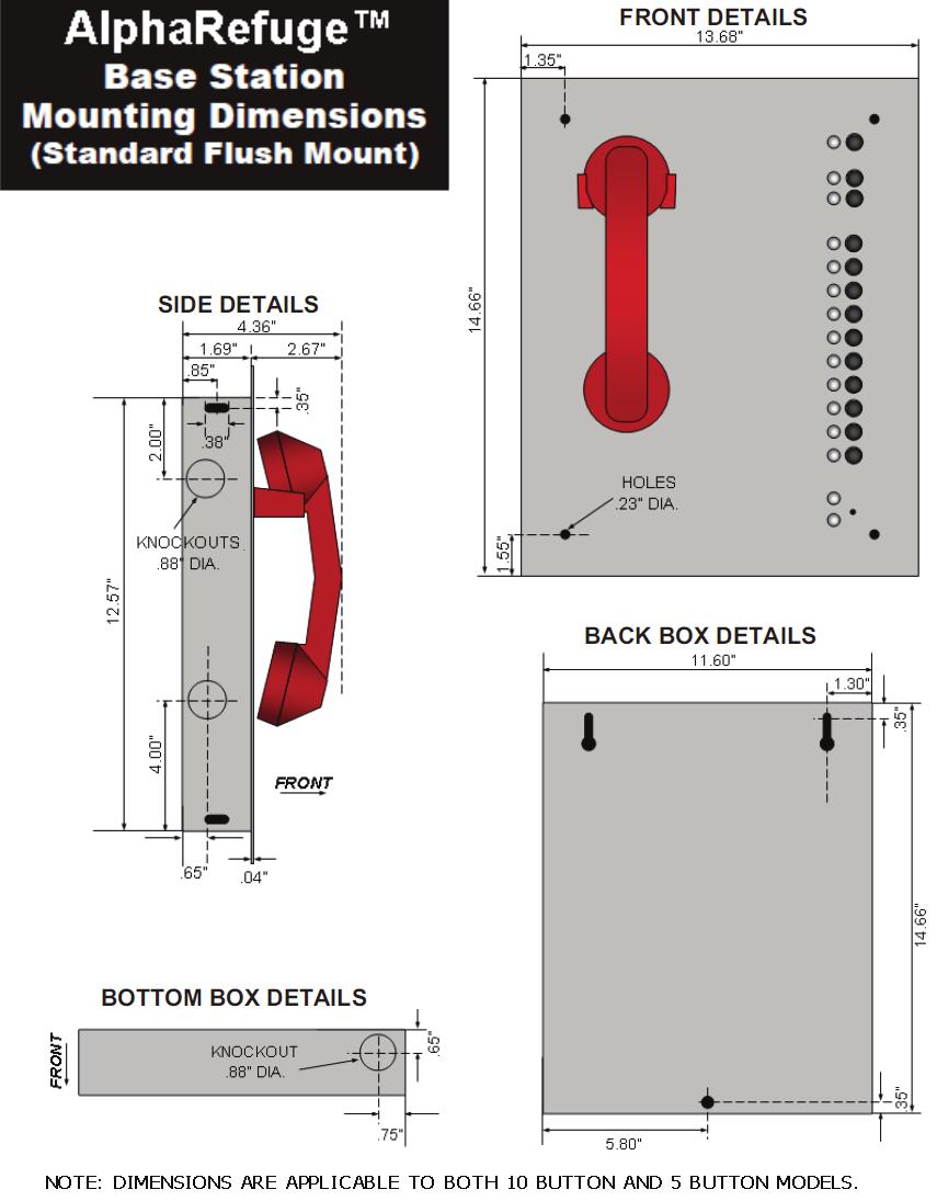
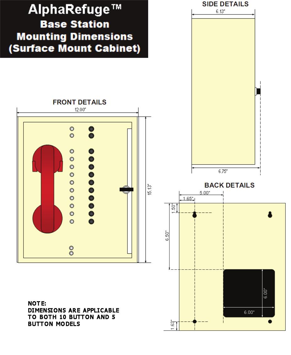
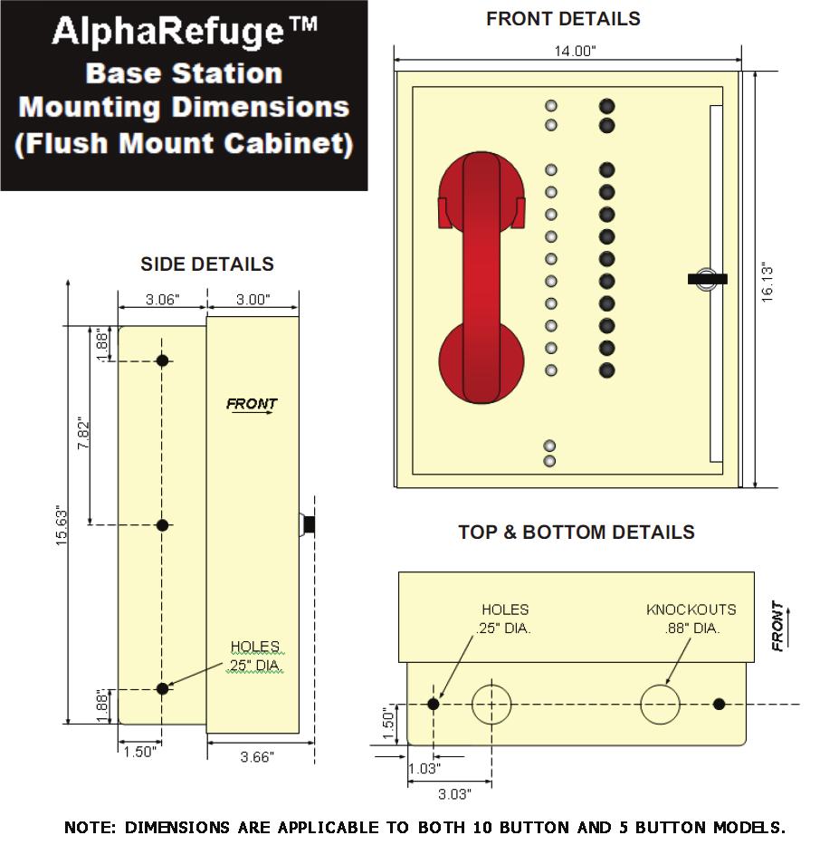
2 Installation Steps: Step 1 Remove the front cover from the SmartRescue and mount the SmartRescue back box to the wall using suitable mounting screws (not included). Step 2 Punch out the conduit knockouts for the analog phone line and phone cabling runs. Step 3 Connect an analog phone line to the outside phone line (Diagram A) Step 4 Connect the backup battery cable to the battery terminal (battery included). (Diagram A) DIAGRAM A 2
3 Step 5 Wire your Refuge Command Center to a 120VAC Power Source (If your Refuge Command Center comes with a plug-in transformer, simply plug it in, and connect to 24VDC on RCC board). Connect the hot wire of the 120vac to the L screw Connect the neutral wire of the 120vac to the N screw Connect the ground wire of the 120vac to the ground screw Connect one lead of the DC power connection to the V screw and the other to the +V screw, polarity is not important. Connect the DC power connection to the SmartRescue. The power connection is on the lower left hand side of the board. 3


4 Wiring Refuge Call Boxes to Refuge Command Center Step 6 Wire the Refuge Call Boxes to the Reguge Command Center Refuge Call Box *Use 22 or 24 AWG 2-pair twisted, shielded cable between the phones and the SmartRescue. The maximum communication run is 5,100 Connecting wire run: To Refuge Command Center: Insert 4 wires for each phone as shown below. To Refuge Call Box: Wire out to a standard 2-pair RJ11 phone jack. Connect this jack to the 5 cord supplied by Alpha. Refuge Command Center The Refuge Call Boxes come with a 5 cord with an RJ11 on both ends. If you received a spade connector, your company requested it. Wire according to your company guidelines. *Shields from the cabling runs (if used) should be attached to one of the mounting screws on the SmartRescue housing. 4
5 Step 7 Mount the front cover back onto the enclosure. Programming the Refuge Command Center Step 8 Programming Options for Refuge Command Center Option 1 (Factory Default) The Emergency Phones will call directly offsite and not stop at the Refuge Command Center. That phone s button will light at the Refuge Command Center during the call. (Keep in Default Mode if site is not manned 24/7 to answer calls onsite) Option 2 Program the Refuge Command Center to Allow the Emergency Phones to call it first, then outside number(s): (Used when staff are available at certain times to answer calls) 1. Hold down Red Disconnect and Submaster 1 buttons for 5 seconds 2. Release buttons (you will hear a confirmation tone) 3. Press Phone 2 button, then Red button, and then the Phone 1 button 4. Press Submaster 2 button, then Submaster 1 button (you will hear a confirmation tone) *Note: If you need to restore the Refuge Command Center to Default Mode see page 11. 5
6 Powering The Refuge Call Boxes Step 9 Provide power to the Refuge Call Boxes through one of the following 3 options: Option 1: Powering up to ten Refuge Call Boxes via PWR2410A Power Supply Use 1-pair 18 AWG wire for power, maximum distance of 5,100 Do NOT wire more than 3 devices per wire run and a maximum of 11 devices per Power Supply Option 1: Transformers (Only applies if your phone comes with one supplied by Alpha) Option 2: Powered Directly by Elevator Car 6
, Stop If using two emergency numbers: Press 2, Enter, (Emergency Number), Stop Repeat for up to 5 total emergency numbers To exit programming")
7 Programming The Refuge Call Boxes Step 10a Program appropriate options for each of your Refuge Call Boxes Option 1: Bypass Refuge Command Center and Dial Directly to Offsite Number(s) Press Enter to get into program mode Press 1, Enter, (Emergency Number), Stop If using two emergency numbers: Press 2, Enter, (Emergency Number), Stop Repeat for up to 5 total emergency numbers To exit programming mode: Press and hold Stop for 2-3 seconds until warble sound Option 2: Call Refuge Command Center and if No Answer, Dial Offsite Number(s) Press Enter to get into program mode Press 1, Enter, (Emergency Number), Stop Press 2, Enter, (same Emergency Number as entered in b.), Stop To exit programming mode: Press and hold Stop for 2-3 seconds until warble sound Step 10b Program the Location Message NOTE: This Should ALWAYS be done, unless your call center requests otherwise!!! Press Enter to get into program mode To turn on message, press 1, 3, Enter, 2 For no message, press 1, 3, Enter, 0 Press 6, Record, (wait for beep, speak your message), Stop To program frequency of message, press 1, 3, Enter, 1 = plays message once 2 = plays message twice (this is standard configuration) 3 = plays message until the called party presses * on their phone To exit program mode, press and hold Stop for 2-3 seconds until warble sound 7
8 System Operation & Testing A. Once finished, the following Refuge Command Center LEDs should be lit: Power LED, located on bottom edge of the faceplate, will be constant lit green Battery LED, also located on bottom edge of the faceplate, will be constant lit. Red = Low level charge Yellow = Mid level charge Green = Full Charge B. Initiate a Call to an Emergency Phone or Sub-Master from the Refuge Command Center: Lift handset on Refuge Command Center Press the Talk button for the corresponding Refuge Call Box or Sub-Master you wish to call into The green LED will light next to that button You should have two-way communication to that device You can place the device on hold by pressing the Talk button a second time To resume communication, press the Talk button a third time To disconnect, hang up the Refuge Command Center handset C. Emergency Phone places a call into the Base Station: You will hear an alternating audible tone at the Refuge Command Center indicating a call has been initiated by one of the phones The corresponding green LED will light on the Refuge Command Center next to the phone that placed the call Lift the handset and there is two-way communication between the Refuge Command Center and the Refuge Call Box. The handset can be hung up on the Refuge Command Center at any time to end the call D. Refuge Call Box places a call to the Refuge Command Center then an Outside Number, or Just to an Outside Number: You will hear an alternating audible tone at the Refuge Command Center indicating a call has been initiated by one of the Refuge Call Boxes (if programmed to call outside line only, no tone) The corresponding green LED will light on the Refuge Command Center next to the Refuge Call Box that placed the call If call is not answered at the Refuge Command Center, the Refuge Call Box will hang up and dial the second number programmed into the phone The CO Line LED, located next to the red button, will also be lit indicating that the outside line is active. Two-way communication can then take place between the outside line and the Refuge Call Box once the call is answered The Refuge Command Center can join the conversation by lifting the handset To talk to rescue services only from the Refuge Command Center, place the Refuge Call Box on hold by pressing the corresponding Talk button. To bring them back into the conversation, press the Talk button again. To disconnect rescue services, press the red button at the top of the Refuge Command Center faceplate. The Rescue Services LED will go off and leave you communicating with the Refuge Call Box only. Handset on the Refuge Command Center can be hung up at any time to end the call. If above testing works and voice communication is clear, congratulations, you have successfully installed the system! 8

9 Appendix System Supervision NFPA-Required for Area of Refuge Systems, not Required for Elevator Industry NFPA All pathways between a remote area of refuge station and the central control point shall be monitored for integrity Power Supplies: All control units shall meet the power supply requirements of section 10.6s Monitoring Integrity of Power Supplies Unless otherwise permitted or required by and all primary and secondary power supplies shall be monitored for the presence of voltage at the point of connection to the system Failure of either the primary or secondary power supply shall result in a trouble signal in accordance with section The secondary power supply (battery back up) shall have sufficient capacity to operate the system under quiescent load (system operating in a nonalarm condition) for a minimum of 24 hours and, at the end of that period, shall be capable of operating all alarm notification appliances used for evacuation or to direct aid to the location of an emergency for 5 minutes. 9


10 Appendix Phone Line Supervision Alpha Refuge Call Boxes have a built-in Line Check Feature. The station constantly looks for a phone line. When a phone line is not detected it will trigger the onboard relay. Connect the relay to an alarm device for notification. Adjusting Volume on Refuge Call Boxes Locate the silver VR1 port on the bottom right corner of the Refuge Call Box board Using a fine Philips Head screwdriver, turn the VR1 clockwise to increase the volume and counterclockwise to decrease the volume. 10
 Press Phone 2 button, then")
11 Appendix Refuge Call Box System Activation Relay When an Emergency phone has been activated, this relay changes state and can be connected to an alarm panel, strobe, or other notification means. Restoring Refuge Command Center Factory Default Settings Hold down Red Disconnect and Submaster 1 buttons for 5 seconds Release buttons (you will hear a confirmation tone) Press Phone 2 button, then Red button, then Submaster 2 button, and then the Phone 5 button Press Submaster 2 button, then Submaster 1 button (you will hear a confirmation tone) 11
12 Appendix Troubleshooting PROBLEM Power LED is not illuminated: Battery LED is not illuminated or always shows red: LEDs on SmartPhone flash when button is pressed: Submaster and Phone LEDs blinking on Refuge Command Center: Refuge Command Center LEDs stay on: Two-way communication from Refuge Call Box is poor: Refuge Command Center will not dial phones: Refuge Command Center will dial Refuge Call Boxes, but Call Boxes will not dial Command Center: No sound or tone on SmartRescue handset: Dial tone present on SmartRescue handset and phone is not calling out: POSSIBLE CAUSE & SOLUTION Check to make sure the transformer is connected to a good 120V power source. If 24V powered, check the power supply. Make sure power connection on the circuit board is secure. Battery has not charged for long enough. Wait 18 hours for the battery to trickle charge. When fully charged it will have 19v. Battery plug is not connected to circuit board. Verify connection. Battery is worn. It is recommended to replace every 2 years. Verify the phone line is working and is connected properly. Verify dial tone is present at the Refuge Command Center. Verify power is applied and the backup battery is connected properly to the Refuge Command Center board. Wires may be crossed. Verify wiring from the Refuge Command Center to the Refuge Call Boxes is correct. There is likely feedback on the line. Adjust the VR1 and VR2. Verify wiring is not spliced onto the phone line cord. Verify wires are connected properly from the Refuge Command Center to the Refuge Call Box(es). No outside phone line connected to Refuge Command Center. Phone line connected does not have working 24v to 52v. Line connected has voltage but does not have working dial tone. Plug analog phone into phone line and place a call out to verify line. Verify 24v power is connected to the SmartRescue base. There should not be a dial tone on the SmartRescue handset. Wire pairs are out of order. Verify wire pairs are connected to the correct pins. Wires are shorted and need to be replaced. ALPHA COMMUNICATIONS 42 Central Drive Farmingdale NY TOLL-FREE TECHNICAL LINE Phone: Fax: WEBSITE: info@alphacommunications.com 12
13 13
14 14
15 15
16 16
17 RCB2100SF Flush Mount St. Steel Remote Call Box Station 17
18 RCB2100SF Flush Mount St. Steel Remote Call Box Station 18
Installation & Operations Manual
 Installation & Operations Manual Emergency Call Box 2100-986DA 2100-986DAI Made in the USA 2 Year Warranty N56W24720 N. Corporate Circle Sussex, WI 53089 800-451-1460 www.rathcommunications.com RP85000986DA
 800-451-1460 www.area-of-refuge.com BASE STATIONS CALL BOXES SIGNAGE Area of Refuge/Elevator Landing Two-Way Communication Systems www.area-of-refuge.com Nurse Call Systems www.rathnursecall.com Pool Phones
TrueCom. Building Communications Systems 5115-Series , Area of Rescue Communications System. Description
 TrueCom Building Communications Systems 5115-Series 5115-9001, -9002 Area of Rescue Communications System Description The Simplex 5115-9001 and -9002 Area of Rescue Communications System provides buildings
Alarm Tone Generator Model AG17
 Alarm Tone Generator Installation & Operation P005089 Rev. C 150930 9/30/2015 12:25 PM Ph: 403.258.3100 \ email:info@guardiantelecom.com \ www.guardiantelecom.com Table of Contents Package Contents...
Interrogator 200 Audio Verification Module (AVM)
") Interrogator 200 Audio Verification Module (AVM) Document Number: 466-1153 Rev. B July 1996 Audio Verification Module Use a maximum of 500 feet of cable for all speakers and microphones. For example, if
Interrogator 200 Audio Verification Module (AVM) Document Number: 466-1153 Rev. B July 1996 Audio Verification Module Use a maximum of 500 feet of cable for all speakers and microphones. For example, if
Computer Room Guard Model VM Manual and Installation Instructions
 Computer Room Guard Model VM500-8 Manual and Installation Instructions For units purchased since December 2004 Index Page General Description 3 Installation, Wiring Diagram 3-5 Accessing the Computer Room
Public Safety DAS Annunciator Panel
 Public Safety DAS Annunciator Panel 120 VAC Models: 1221-A, 1221-B, 1221-C Revision D 91117 48 VDC Models: 1221-A-48, 1221-B-48, 1221-C-48 24 VDC Models: 1221A-24, 1221-B-24, 1221-C-24 CAUTION: (Read This
PERS-3600 PERSONAL EMERGENCY REPORTING SYSTEM INSTALLATION & OPERATION INSTRUCTIONS
 PERS-600 PERSONAL EMERGENCY REPORTING SYSTEM BY BY INSTALLATION & OPERATION INSTRUCTIONS (760) 8-7000 USA & Canada (800) -587 & (800) 9-0 Toll Free FAX (800) 68-0 www.linearcorp.com CONTENTS CONTROL AREA
Models NFPA 1221-A, NFPA 1221-B Public Safety DAS Annunciator Panel. Revision E 61117
 Models NFPA 1221-A, NFPA 1221-B Public Safety DAS Annunciator Panel Revision E 61117 CAUTION: (Read This First) This panel has been designed to make it nearly bullet proof to mistakes made when wiring
CPS-1 USER S MANUAL AIR INLET / CURTAIN CONTROL
 CPS-1 USER S MANUAL AIR INLET / CURTAIN CONTROL temperature / static pressure DIFF Opn Clo ALARM HI F2 DELAY ALARM LO OPEN DELAY CLOSE ADJUST Varifan + CPS-1 CPS-1 Although the manufacturer has made every
N-8000 SERIES IP INTERCOM SYSTEM
 N-8000 SERIES IP INTERCOM SYSTEM IP Network-Compatible Intercom System with Packet Audio Technology developed with cutting-edge TOA technological strengths for greater versatility and improved sound quality
A1UL PERS. Personal Emergency Response System. For Technical Support Please Contact Your Service Provider Or Distributor
 A1UL PERS Personal Emergency Response System TABLE OF CONTENTS 1. READ THIS FIRST... 1 2. SYSTEM OVERVIEW.. 1 3. COMPONENTS 2 4. UNIT OPERATION! Standby Mode.. 3! Emergency Activation. 3! Answering Incoming
TrueAlert Addressable Notification
 UL, ULC Approved* TrueAlert Addressable Notification 4009 IDNAC Repeater; Power and Distance Extender Features IDNAC Repeaters provide enhanced power delivery to TrueAlert/ TrueAlert ES addressable notification
Memcom Emergency Telephone
 Memcom Emergency Telephone Installation Guide Ref No. 450 900 (GB) Version 2 + + Simple wiring for quick installation + + Integrated LCD display shows you what you have programmed + + All code based programming
Staff Alert Panel. Installation Guide. Using the Touchpad Exit Controller B
 Staff Alert Panel Using the Touchpad Exit Controller Installation Guide 3125 North 126th Street, Brookfield, WI 53005 phone: 800.669.9946 fax: 262.790.1784 www.rft.com 2015 RF Technologies, Inc. All specifications
MST-1. Varifan USER S MANUAL MST-1 ADJUST. 9 per day HI F2. DIFF on off TIMER. reduc.
 USER S MANUAL ALARM HI F2 COOL / HEAT ALARM LO DIFF on off PERIOD TIMER L IMIT reduc. 9 per day 88 ADJUST Varifan + Although the manufacturer has made every effort to ensure the accuracy of the information
Basic Installation Manual
 SAR SAR-V.7 Program or Higher Alarm Equipment for Lifts Basic Installation Manual in HIDRA System controllers Revision 0 (EN) NOTES FROM THE MANUFACTURER Carlos Silva SA shall not be responsible for any
D1255RB/D1256RB/D1257RB
 D1255RB/D1256RB/D1257RB EN Installation Instructions Fire Keypads and Fire Alarm Annunciator D1255RB/D1256RB/D1257RB Installation Instructions Listings and Approvals Listings and Approvals UL 365 UL 609
Addressable NAC Output Module D327A
 Installation Instructions Notice Addressable NAC Output Module D327A These instructions cover the installation of the D327A Addressable NAC Output Module in an analog system controlled by a Bosch D8024,
Beacon 200 Gas Monitor Operator s Manual. Part Number: RK Released: 6/6/08
 Beacon 200 Gas Monitor Operator s Manual Part Number: 71-2102RK Released: 6/6/08 Table of Contents Chapter 1: Introduction.................................................3 Overview.............................................................3
M O D E L S F I R E G A R D M C V ADVANCE FIRE CONTROL RELEASE DEVICE
 Cookson 100 Elmwood Avenue Crestwood Industrial Park Mountaintop, PA 18707 Phone: 800-233-8366 Fax: 800-526-0841 CornellCookson.com O W N E R S M A N U A L M O D E L S F I R E G A R D M C F I R E G A R
ACC-25/50ZST. Zoned System Voice with Telephone Evacuation Control Panel
 ACC-25/50ZST Zoned System Voice with Telephone Evacuation Control Panel General The AUDIO COMMAND CENTER 25/50 Zone System with FireFighters Telephone (ACC-25/50ZST) is a state-of-the-art Emergency Voice
Security System. User Guide for the LED Command Center
 Security System User Guide for the LED Command Center National Security Systems Inc (800)457-1999 MY SECURITY COMPANY IS: CALL BEFORE TEST: THIS SECURITY SYSTEM IS CONNECTED TO TELEPHONE NUMBER: THE SECURITY
July 14, 1999 DF C-100.
 www.firelite.com GENERAL The Fire Lite FIRE COMMAND 25/50 is a state-of-theart, compact, stand-alone or slave Emergency Voice Evacuation Control Panel (VECP). The FIRE COMMAND 25/50 is offered in a self-contained,
RM-1 Series. Remote Microphones. (RM-1, RM-1SA) Document Revision B RM-1 RM-1SA. RM-1 on ADP-4 dress panel. RM-1SA in a CAB-RM or CAB-RMR
 Document Revision B RM-1 RM-1SA. RM-1 on ADP-4 dress panel. RM-1SA in a CAB-RM or CAB-RMR") This product has been certified to comply with the requirements in the Standard for Control Units and Accessories for Fire Alarm Systems, UL 864 9th Edition. The following products have not received UL
This product has been certified to comply with the requirements in the Standard for Control Units and Accessories for Fire Alarm Systems, UL 864 9th Edition. The following products have not received UL
DESCRIPTION INSTALLATION
 DESCRIPTION The Model 10A11 Two-Way Audio/Voice Alarm Module allows two-way communication with a central station after an alarm, paging and listening from an on-premises or remote phone, annunciation of
GENERAL STANDARD FEATURES. ISO-9001 Engineering and Manufacturing Quality System Certified to International Standard ISO-9001 PATENT PENDING
 GENERAL The VEC 25/50 is a state-of-the-art, compact, stand-alone or slave Emergency Voice Evacuation Control. The VEC 25/50 is offered in a self-contained, cost-effective design and includes a 25 Watt,
All-In-One Wireless Security System V3.2 Programming Guide. Model # MG6130 / MG6160
 All-In-One Wireless Security System V3.2 Programming Guide Model # MG6130 / MG6160 We hope this product performs to your complete satisfaction. Should you have any questions or comments, please visit www.paradox.com
LiftMaster 300 Windsor Drive Oak Brook, IL LiftMaster.com
 LiftMaster 300 Windsor Drive Oak Brook, IL 60523 LiftMaster.com O W N E R S M A N U A L MODELS LM21AFCB LM21AFCBVB B ADVANCE FIRE CONTROL RELEASE DEVICE FM APPROVED TABLE OF CONTENTS INTRODUCTION General
Setup & Operation Index
 SENTRY PreSTAT SIMPLEX PANEL Installation and Operation Manual Environment One Corporation Setup & Operation Index Setup & Operation Index...2 Sentry PreSTAT Menu Flowchart...3 Overview...3 Wiring Instructions...5
Voice Board. Installation and Programming Guide. Runner 4/8,PowerWave 4/8/16 &, Elite64. Add-on Board For Storing Recorded Voice Messages
 ELECTRONIC ENGINEERING LTD. Voice Board Runner 4/8,PowerWave 4/8/16 &, Elite64 Add-on Board For Storing Recorded Voice Messages And listen-in. Installation and Programming Guide. P/N 7101372 Rev. C V.K
Memcom + Emergency Telephone
 Memcom + Emergency Telephone Installation Guide Ref No. 453 901AU (GB) Version 4 + + Simple wiring for quick installation + + Integrated LCD display shows you what you have programmed + + All code based
QUICKFIT INSTALL HOOK-UP SHEET FOR ESL KIT REV 1.17 OP
 QUICKFIT INSTALL HOOK-UP SHEET FOR ESL KIT REV 1.17 OP PROGRAMMING STARTS Entering Installer mode If you want to get into program mode press followed by your installer code, default set to 000000
Rev C May GE Interlogix. Part No: R. CareGard. User Guide
 g 466-1936 Rev C May 2003 GE Interlogix www.ge-interlogix.com Part No: 60-883-95R CareGard User Guide FCC Notices FCC Part 15 Information to the User Changes or modifications not expressly approved by
SECTION FIRE ALARM SYSTEMS
 SECTION 28 3100 PART 1 -GENERAL 1.01 RELATED DOCUMENTS Drawings and general provisions of the Contract, including General and Supplementary Conditions and Division 1 Specification Sections, apply to this
WHO IS RATH COMMUNICATIONS?
 NURSE CALL Tone & Visual Nurse Call Systems AREA OF REFUGE Area of Refuge & Elevator Landing Two-Way Communication Systems SECURITY Blue Light & Industrial Phones ELEVATOR PHONES POOL PHONES MADE IN THE
The Windcrest Remote Alarm for Passenger and Goods Lifts with Optional BS EN81-28 & BS EN81-70
 The Windcrest Remote Alarm for Passenger and Goods Lifts with Optional BS EN81-28 & BS EN81-70 1. Identify the Equipment and carry out a Risk Assessment before installation AD1000EN- 1R Main Unit EN1 Speaker
INSTALLATION INSTRUCTIONS
 INSTALLATION INSTRUCTIONS The SensorNet I/O Module provides attachment for up to 32 alarms and up to 16 switched devices. An RS-232 or RS-422 communications port is also provided for receiving serial alarms.
Supervised Security System Owner's Guide
 Owner's Guide PSC06 READ THIS FIRST This equipment generates and uses radio frequency energy, and if not installed and used properly, that is, in strict accordance with the manufacturers instructions,
June 10, 2002 DF C S2424
 GENERAL www.firelite.com The Fire Lite FIRE COMMAND 25/50X is a state-of-theart Emergency Voice Evacuation Control Panel (VECP), with significant technological enhancements that set it apart from other
Quick Installation Manual LED Touch Keypad Autodial Wireless Alarm System
 Quick Installation Manual LED Touch Keypad Autodial Wireless Alarm System By shield4u http:// (Version 20110816) A. Alarm Understanding Away Disarm Home Emergency Function Signal Interpretation Buzzer
RAZOR RZR SERIES DIE CAST ALUMINUM LED EXIT SIGNS INSTALLATION AND OPERATING INSTRUCTIONS IMPORTANT SAFEGUARDS READ AND FOLLOW ALL SAFETY INSTRUCTIONS
 RAZOR RZR SERIES DIE CAST ALUMINUM LED EXIT SIGNS INSTALLATION AND OPERATING INSTRUCTIONS IMPORTANT SAFEGUARDS When using electrical equipment, basic safety precautions should always be followed including
PS6 SERIES. Installation PS6 SERIES. Power Supplies c/w Fire Panel Interface, EOL Trigger and Standby Power Option
 Installation PS6 SERIES Power Supplies PS6 SERIES Power Supplies c/w Fire Panel Interface, EOL Trigger and Standby Power Option Installation and Specifications Manual ISDPS6_SERIES 08121590 PCN15016 R05/15GR
ANNUNCIATOR FIXED MODULE
 12 Clintonville Road Northford, CT 06472 Phone: 203-484-7161 Fax: 203-484-7118 THE ANNUNCIATOR FIXED MODULE Installation Manual for the AFM-16ATF and AFM-32AF Annunciator Modules Document # 15970 3/27/95
Installation Instructions
 Fixture Mount Night Light Controller SPECIFICATIONS Power.....................................120VAC, 60Hz Relay Type..................................Form C, N.O. Load Requirements @120VAC......................................500W..........................
DYGIZONE GJD910 Lighting Controller & Enunciator
 DYGIZONE GJD910 Lighting Controller & Enunciator MASTER WIRING IDENTIFICATION Power up to the DygiZone and you will see: All the LED s (red,yellow,green and blue buttons) will flash All the LCD icons will
Refrigerator/Freezer Guard Models VM605, VM605E. Property Guard Models VM610, VM610E. Temperature Monitor and Alarm
 Refrigerator/Freezer Guard Models VM605, VM605E Property Guard Models VM610, VM610E Temperature Monitor and Alarm Microtechnologies, Inc. www.temperatureguard.com sales@temperatureguard.com support@temperatureguard.com
EVO192 v3.0 Fire and Burglary What s New
 EVO192 v3.0 Fire and Burglary What s New Compatibility: EVO192 v3.0 TM50 v1.31 K641 v2.41 Overview: CP-01 Compliancy Wiring Diagram The following sections/options have been added to the EVO192 panel. They
4286/4500 Voice Module Set up and Troubleshooting
 4286/4500 Voice Module Set up and Troubleshooting In this document we will discuss the following: 1. Pre-Installation Notes 2. The Wiring 3. System Programming 4. 4286 1 st Time Accessing and Programming
TABLE OF CONTENTS GENERAL... 2 A. DEFINITIONS DIGITAL, ADDRESSABLE FIRE ALARM SYSTEM... 2
 Division 28 ELECTRONIC SAFETY AND SECURITY TABLE OF CONTENTS 28 0000 GENERAL... 2 A. DEFINITIONS...2 28 3111 DIGITAL, ADDRESSABLE FIRE ALARM SYSTEM... 2 A. DESIGN REQUIREMENTS...2 B. CONSTRUCTION REQUIREMENTS...2
ERS-3600B. PERS-3600B Personal Emergency Reporting System
 PERS-3600B Personal Emergency Reporting System ERS-3600B A Complete Emergency System For Comprehensive Care The Linear PERS-3600B includes a built-in speakerphone and reminder message capability, providing
MEDICAL ALERT SETUP GUIDE
 MEDICAL ALERT SETUP GUIDE GETTING STARTED STARTED You have made a great decision to protect yourself with Medical Alert! Be sure to wear your wrist button or neck button everyday to stay protected all
AT60 AUTO DIALLER User Guide
 AT60 AUTO DIALLER User Guide Power on LED MIC Power on LED MIC 1 2 3 4 5 6 7 8 9 REC/PLAY 0 STORE M1 M2 M3 Table of Contents I. Overview 3 II. Installation 4 III. Initialize the Dialer 5 IV. Using the
FreezeAlarm Dialer Pro
 FreezeAlarm Dialer Pro User Manual for FA-800E Thank you for purchasing our FreezeAlarm Dialer Pro. This instruction manual covers installation for model FA-800E. General Description The FA-800E automatically
FreezeAlarm Dialer FA-700 Installation and Operations Manual
 FreezeAlarm Dialer FA-700 Installation and Operations Manual Emerson Control Products Inc. 1724 Lake Drive West Chanhassen, MN 55317 Document No. 42420079B Table of Contents Cautions and warnings... 4
Property of Monitronics Inc
 Enter Program Press CODE key + * + 2468 + 1 (also try 2121) Installer Options Move to location Program location Exit Program Default Panel Hex Program Code + * + Installer Code + 1 = Enter Programming
Installation Guide for AL600ULM. Multi-Output Access Control Power Supply Charger. Rev
 Installation Guide for AL600ULM Multi-Output Access Control Power Supply Charger Rev. 091800 1 AL600ULM - Multi-Output Access Control Power Supply/Charger Overview: The AL600ULM multi-output access control
INSTRUCTIONS CONTROL PRODUCTS INITIAL SET-UP. Innovative Technologies in Custom Electronic Design & Manufacturing
 INSTRUCTIONS CONTROL PRODUCTS Innovative Technologies in Custom Electronic Design & Manufacturing Thank you for purchasing the minialarm Compact Security System. The minialarm is a self contained security
Fire Burglary Instruments Inc. XL-2G Gold Control/Communicator Installation Training Seminar Rev. 5/96
 Fire Burglary Instruments Inc. XL-2G Gold Control/Communicator Installation Training Seminar Rev. 5/96 XL-2G Gold Product Overview 7 Zones (6 programmable + panic or keyswitch zone) Fast Loop Response
Installation Instructions for W2H Series Signals
 Installation Instructions for W2H Series Signals IF1513 A Description and Operation DIMENSIONS W2H A 8 7/8" (225 mm) B 8 1/4" (210 mm) C 13" (330 mm) Figure 1. Speaker/Amplifier Dimensions The W2H signaling
User instructions EasyAlarm CONTROL
 LEITRONIC AG Swiss Security Systems TELEMONITORING / TELECONTROLLING SYSTEM User instructions EasyAlarm CONTROL Interface-Modul Potential free relay switch: 10..230V AC or DC AC-switch: max. 2A / 230V
Analog Room Pressure Monitor RPC Series
 Description The Room Pressure Monitor is used to measure differential pressure in the range of 0.125 to 1"wc or 30 to 250 Pa. It combines precision high sensitivity silicon sensing capabilities and the
Preface. Thank you for purchasing our GSM Security Alarm System ( The System )! The System will keep your home and property safe around the clock.
! The System will keep your home and property safe around the clock.") Preface Thank you for purchasing our GSM Security Alarm System ( The System )! The System will keep your home and property safe around the clock. The GSM Security Alarm ( The Alarm ) adopts the most advanced
Preface Thank you for purchasing our GSM Security Alarm System ( The System )! The System will keep your home and property safe around the clock. The GSM Security Alarm ( The Alarm ) adopts the most advanced
Installation Instructions. PS902 Power Supply. These instructions cover the following parts: PS902 Power Supply Specifi cations:
 F1! 44487023 These instructions cover the following parts: PS902 Power Supply Installation Instructions! DANGER: To avoid risk of electric shock, turn off AC power before installing or servicing PS902
RPSMLR2 RPSMLR2BB. Panic Device Power Controller Installation Guide LISTED. Rev
 RPSMLR2 RPSMLR2BB Panic Device Power Controller Installation Guide LISTED Rev. 102715 Overview: RPSMLR2BB, RPSMLR2 will operate up to two (2) 24VDC panic hardware devices simultaneously. It is designed
ACCURATE ELECTRONICS INC
 ACCURATE ELECTRONICS INC Page 1 of 7 Model 108078 2 Sept 09 WWW.ACCURATE.ORG PO BOX 1654 97075-1654 8687 SW Hall Blvd 97008 BEAVERTON OR USA 503.641.0118 FAX 503.646.3903 Practice Section 108078 Rev A
Security System. User s Guide for the Text Command Center
 User s Guide for the Text Command Center MY ALARM COMPANY IS: CALL BEFORE TEST: THIS SECURITY SYSTEM IS CONNECTED TO TELEPHONE NUMBER: THE SECURITY CONTROL PANEL IS CONNECTED TO THE PHONE JACK LOCATED:
To activate using remote control: press [ ] key once. To activate using keyboard: on panel keyboard [ ] keys once.
![To activate using remote control: press [ ] key once. To activate using keyboard: on panel keyboard [ ] keys once.](/thumbs/93/113878877.jpg "To activate using remote control: press [ ] key once. To activate using keyboard: on panel keyboard [ ] keys once.") Table of Content 1.1General Description----------------------------------------------------------------------2 2.2System Setup-----------------------------------------------------------------------------3
Table of Content 1.1General Description----------------------------------------------------------------------2 2.2System Setup-----------------------------------------------------------------------------3
D326A/D334A/D339A. Installation Instructions. Point Contact Modules
 D326A/D334A/D339A EN Installation Instructions Point Contact Modules D326A/D334A/D339A Installation Instructions 1.0 Description Notice Use these instructions to install the D326A, D334A, and D339A Point
VIDEO INTERCOM SYSTEM 2000F
 USER MANUAL FOR VIDEO INTERCOM SYSTEM 2000F User Manual for Video Intercom System 2000F rev5. 12-16-13 Page 1 of 5 TABLE OF CONTENTS Title Page Number RECEIVING CALLS FROM THE CONCIERGE..3 CALLING THE
Remote NAC Power Supply D7038
 Operation and Installation Guide Remote NAC Power Supply D7038 D7038 REMOTE NAC POWER SUPPLY Page 2 2005 Bosch Security Systems Contents Contents 1.0 Overview...5 1.1 Module Control...5 1.1.1 Option Bus
2 Wire Nuts (or other approved wire connectors) (Field-supplied) Push Button(s) Phillips Head Screwdriver (Field-supplied) Control-R Module
 (Field-supplied) Push Button(s) Phillips Head Screwdriver (Field-supplied) Control-R Module") This guide is designed to help you quickly install the push button for on-demand recirculation with Rinnai SENSEI tankless water heaters using a dedicated return line in the plumbing system. IMPORTANT
This guide is designed to help you quickly install the push button for on-demand recirculation with Rinnai SENSEI tankless water heaters using a dedicated return line in the plumbing system. IMPORTANT
TFD-1 Installation & User s Guide
 TFD-1 Installation & User s Guide TABLE OF CONTENTS CHAPTER 1 - INTRODUCTION... 4 1.1 GENERAL...4 1.2 DESCRIPTION...4 CHAPTER 2 - INSTALLATION... 5 2.1 UNPACKING...5 2.2 MOUNTING...5 2.3 SWITCH SETTINGS...6
Interactive Technologies Inc North 2nd Street North St. Paul, MN Technical Manuals Online! -
 Security System Owner s Manual Interactive Technologies Inc. 2266 North 2nd Street North St. Paul, MN 55109 FCC Notices FCC Part 15 Information to the User Changes or modifications not expressly approved
FTP-1000 Touchpad/Display Installation Manual
 FTP-1000 Touchpad/Display Installation Manual A B 1 2 3 4 5 6 7 8 9 0 * # Stay Away Disarm Quick Exit C D P/N 466-2231 REV B January 2011 Copyright Disclaimer Trademarks and patents Manufacturer Intended
HomeSitter HS-700 Installation and Operations Manual Emerson Control Products Inc Lake Drive West Chanhassen, MN Document No.
 HomeSitter HS-700 Installation and Operations Manual Emerson Control Products Inc. 1724 Lake Drive West Chanhassen, MN 55317 Document No. 41410062C Table of contents Cautions and warnings... 4 Description...
Installation and Operation Manual. Model Q916
 Installation and Operation Manual Model Q916 This manual is suitable for the following components: Part Number Description PANQ916KS Kit (Silver door, silver master room, power supply) PANQ916KG Kit (Grey
MiniAlarm Plus. Model MA-5000
 MiniAlarm Plus 1 Model MA-5000 Thank you for purchasing the MiniAlarm Plus. We are confident this product will provide you with the peace of mind and protection you expect. If you should ever have any
SP-1000X. Panic Device Power Controller Installation Guide. Rev
 TM SP-1000X Panic Device Power Controller Installation Guide Rev. 120213 Overview: SP-1000X will operate up to two (2) 24VDC panic hardware devices simultaneously. It is designed to handle the high current
HOME AUTOMATION, INC. Lumina and Lumina Pro Lighting and Automation System. Quick-Start Installation Guide
 HOME AUTOMATION, INC. Lumina and Lumina Pro Lighting and Automation System Quick-Start Installation Guide Document Number 44I00-1 Rev. 2.12 February, 2006 For complete operation and programming instructions,
Deluxe FreezeAlarm. Model FA-D2
 Deluxe FreezeAlarm Model FA-D2 Thank you for purchasing our Deluxe FreezeAlarm, model FA-D2. If you have any questions or concerns about this product, feel free to contact us. Our phone number, web sites
TECHNICAL DATA. Humidity: 85% Relative Humidity (non-condensing) at 90 F (32 C) maximum.
 at 90 F (32 C) maximum.") September 29, 1997 Firecycle III 433 a 1. PRODUCT NAME VIKING Model E-1 Manufactured 1997 Present 2. MANUFACTURED FOR THE VIKING CORPORATION 210 N Industrial Park Road Hastings, Michigan 49058, U.S.A.
September 29, 1997 Firecycle III 433 a 1. PRODUCT NAME VIKING Model E-1 Manufactured 1997 Present 2. MANUFACTURED FOR THE VIKING CORPORATION 210 N Industrial Park Road Hastings, Michigan 49058, U.S.A.
ACSI MODEL 1410 POWER SUPPLY INSTALLATION INSTRUCTIONS
 II 1400-3 ACSI MODEL 1410 POWER SUPPLY INSTALLATION INSTRUCTIONS Features: For use with doors or groups of doors that must interlock with each other to regulate control of accessing one area from another,
Voice Dialer Temperature & Power Loss Monitor VD-5100-TM / VD-5101-TM
 Innovative Technologies n Custom Electronic Design & Manufacturing General Description The VD-5100-TM (Fahrenheit) and VD-5101-TM (Celsius) Voice Dialer monitors temperature and power status. Upon an alarm
Tek-ENTRY Apartment Entry Systems
 Tek-ENTRY Apartment Entry Systems Submittal Package as of 5/25/2017 Phone: 828.524.9967 Toll-Free: 800.327.8466 Sales: Option 2 Tech Support: Option 3 324 Industrial Park Road Franklin, NC 28734 tektone@tektone.net
FIRE STROBE 2000 INSTALLATION INSTRUCTIONS
 FIRE STROBE 2000 INSTALLATION INSTRUCTIONS I. SITE INSPECTION FOR INSTALLATION A.P.I voice: (858) 292-1561 web: http:// www.firestrobe.com 1. Carefully inspect the area where the Fire Strobe 2000 will
Product Manual SZ1009
 Product Manual SZ1009 Conventional Heating & Cooling Thermostats with Heat Pump Mode Communicating Thermostats Description The SZ1009 is a microprocessor-based mable thermostats designed for conventional
User s Guide. SUB-MA7240O-0001.OG.Solution doc. Created: 6/05/03. Last Updated: 23/09/03. MA7240AO-0001 Version 1.0
 User s Guide SUB-MA7240O-0001.OG.Solution40-111.doc Created: 6/05/03 Last Updated: 23/09/03 MA7240AO-0001 Version 1.0 2 Table Of Contents User List...6 Quick Reference..7 Features...7 Keypad User's Guide...8
Hinesville First United Methodist Church SECTION DIGITAL, ADDRESSABLE FIRE-ALARM SYSTEM
 SECTION 28 3111 DIGITAL, ADDRESSABLE FIRE-ALARM SYSTEM PART 1 - GENERAL 1.01 SUMMARY A. Section Includes: 1. Fire-alarm control unit. 2. Manual fire-alarm boxes. 3. System smoke detectors. 4. Heat detectors.
1. Introduction. 2. Product overview
 1. Introduction The AG400011 GSM Alarm panel is a control panel that is compatible with other H-net security devices from Everspring, such as wireless sensors, remote keyfobs, tags, and keypad. With this
Auto Dialer. Manual E-921APQ E-921GPQ
 Troubleshooting: Auto dialer will not arm/disarm Auto dialer will not dial out Unit doesn t respond to a call-back Difficulty in activating room monitor by telephone remote control Make sure that you have
AVCOM System Installation Instructions
 AVCOM System Installation Instructions Index 1) AVCOM EN-1 System Drawings - AVCOM EN1 System.. Page 1 - AVCOM EN1 with 2COP.. Page 2 - AVCOM EN1 FF System.. Page 3 -AVCOM EN1 Evacuation System Page 4
Series. Access Power Controllers. Installation Guide
 Series Access Power Controllers Installation Guide Models Include: Maxim11 - Power Supply 1: 12VDC @ 3.5 amp or 24VDC @ 2.7 amp. - Power Supply 2: 12VDC @ 3.5 amp or 24VDC @ 2.7 amp. - Sixteen (16) fuse
Power Wave LCD Keypads. Users Operating and Programming Guide Version 2.00
 Power Wave LCD Keypads CR-16S CR-16M Users Operating and Programming Guide Version 2.00 P/N 7102265 Rev. C N.A May 2003 Contents Introduction...4 Meet the PowerWave Alarm Control System... 4 Typical Alarm
Part. Test System Weekly See Watch ~Test. Points
 Part 1. Test System Weekly See Watch ~Test Points 2. 3. 4. 5. 6. 7. 8. Turn System Off Enter your passcode to turn the system off and silence alarms. Turn System All On Press 9 Exit Delay begins If Error
SECTION DIGITAL, ADDRESSABLE FIRE-ALARM SYSTEM
 SECTION 283111 - DIGITAL, ADDRESSABLE FIRE-ALARM SYSTEM PART 1 - GENERAL 1.1 RELATED DOCUMENTS A. Drawings and general provisions of the Contract, including General and Supplementary Conditions and Division
F PC and AO OUTPUT BOARDS INSTRUCTION MANUAL. Blue-White. Industries, Ltd.
 F-2000 PC and AO OUTPUT BOARDS INSTRUCTION MANUAL Blue-White R Industries, Ltd. 500 Business Drive Huntington Beach, CA 92649 USA Phone: 714-89-8529 FAX: 714-894-9492 E mail: sales@blue-white.com or techsupport@blue-white.com
PS1240x Series Dual Voltage Access Control Power Supply Systems Operating and Installation Instructions Rev D.01
 PS1240x Series Dual Voltage Access Control Power Supply Systems Operating and Installation Instructions Warnings and Notices WARNING - To reduce the risk of fire or electric shock, do not expose this product
SIGA-CC1 Single Input Signal Module Installation Sheet
 SIGA-CC1 Single Input Signal Module Installation Sheet Personality codes Use the personality codes described below to configure the SIGA-CC1 module. See Table 1 for listing information Table 1: Personality
GSM RFID VOICE Alarm System
 GSM RFID VOICE Alarm System User s Manual For a better understanding of this product, please read this user manual thoroughly before using it. CONTENTS [Function Instruction] [Control Panel] Control Panel