User's Manual H-VC5. Chore-Logic. H-VC5 User manual. Version HPS 11/11/2006 User manual 1.02 ST50737MA 3/07. Page 1
|
|
|
- Elwin Fowler
- 6 years ago
- Views:
Transcription
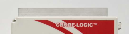
1 Chore-Logic User manual Version HPS 11/11/2006 User manual 1.02 ST50737MA 3/07 Page 1
2 Warranty Chore-Time Hog Production Systems, a division of CTB, Inc., ( Chore-Time ), warrants each new Chore-Time product manufactured by it to be free from defects in material or workmanship for one (1) year from and after the date of initial installation by or for the original purchaser. If such a defect is found by Chore-Time to exits within the one-year period, the Chore-Time will, at its option, (a) repair or replace such product free of charge, F.O.B. the factory of manufacture, or (b) refund to the original purchaser the original purchase price, in lieu of such repair or replacement. Labor cost associated with the replacement or repair of the product are not covered by the Manufacturer. Conditions and Limitations 1. The product must be installed by and operated in accordance with the instructions published by the Manufacturer or warranty will be void. 2. Warranty is void if all components of the system are not original equipment supplied by the Manufacturer. 3. This product must be purchased from and installed by authorized distributor or certified representative thereof or the Warranty will be void. 4. Malfunctions or failure resulting from misuse, abuse, negligence, alteration, accident, or lack of proper maintenance, or from lighting strikes, electrical power surge or interruption of electricity, shall not be considered defects under the Warranty. 5. This Warranty applies only to the system for the care of poultry and livestock. Other applications in industry or commerce are not covered by this Warranty. Chore-time shall not be liable for any Consequential or Special Damage which any purchaser may suffer or claim to suffer as a result of any defect in the product. Consequential or Special Damages as used herein included, but are not limited to, lost or damaged products or goods, costs of transportation, lost sales, lost orders, lost income, increased overhead, labor and incidental costs and operational inefficiencies. THIS WARRANTY CONSTITUTES THE MANUFACTURER S ENTIRE AND SOLE WARRANTY AND THIS MANUFACTURER EXPRESSLY DISCLAIMS ANY AND ALL OTHER WARRANTIES, INCLUDING, BUT NOT LIMITED TO, EXPRESS AND IMPLIED WARRANTIES AS TO MERCHANTABILITY, FITNESS FOR PARTICULAR PURPOSES SOLD AND DESCRIPTION OR QUILTY OF THE PRODUCT FURNISHED HEREUNDER. Chore-Time Distributors are not authorized to modify or extend the terms and conditions of this Warranty in any manner or to offer or grant any other warranties for CHORE-TIME products in addition to those terms expressly stated above. An officer of CTB, Inc. must authorize any exceptions to this Warranty in writing. Chore-Time reserves the rights to change models and specifications at any time without notice or obligation to improve previous models. Effective 07/04 Chore-Time Hog Production Systems A Division of CTB, Inc. 410 N. Higbee Street ٠ Milford, Indiana ٠U.S.A. Phone (574) ٠ Fax (574) hog@choretime.com٠ Internet: http// Page 2
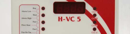
3 OPERATION MANUAL Version HPS The is a stand-alone climate control unit. The unit has 5 outputs and two temperature sensors. The unit has a built variable output regulator. The unit has a built in alarm for low and high temperatures, variable output regulator failure and power failure. 1. Installation Recalling set points Changing set points Functions Wiring diagram Page 3
4 1. Installation Open the two screws on the front panel 1. Connect the to the wall in a dry place at least 1 meter away from the electrical cabinet. 2. Connect the temperature sensors to the temperature sensor inputs IN1 and IN2. See drawing 1. TEMP jumper (J18) must be shorted out. See drawing 2 The sensors can be placed up to 100 meter from the main unit with an ordinary twowire cable. The sensor has no polarity. Drawing 1 Sensor 1 Sensor 2 Drawing 2 J18 Temperature sensor jumper If a temperature sensor or its cable is disconnected or shorted the sensor reading will display OPEN Page 4

5 3. Connect the OUT phase, neutral and ground to the Floor heat pad (see drawing 3). Maximum output 20 AMP. Be sure that the side heat sinks bars and fan are in an open area with proper ventilation. Drawing 3 Connect 110V Connect the phase, neutral and ground wiring coming from the Floor heating pad here. Maximum output 20AMP Page 5
. 5. Connect a 110V cable to the unit. 6.")

6 4. Connect the alarm relay output to the alarm system of your choice. The alarm relay is a dry contact 2 Amp/220V NO/NC (see drawing 4). 5. Connect a 110V cable to the unit. 6. Connect the PC communication wires (optional) (see drawing 5) 7. Close the panel with the two screws. Drawing 4 Heat Fan1 Fan2 Cool Alarm Relay inputs. Maximum 2AMP Drawing 5 Connect the 5 wires to the AG box (supplied separately, optional). Connect A to A, B to B and so on for each of the 5 wires. Page 6
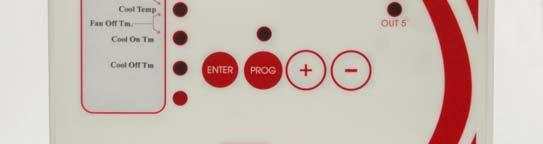
7 Operation The will display the current air temperature (sensor 1) and current floor temperature (sensor 2). The temperature reading can be displayed either in Celsius or Fahrenheit (see Temperature setup, page 11). If there is an alarm the unit will display the alarm number. Turn on power. Each time the power is connected to the unit the version number will briefly appear on the display (r321). After 5 Seconds the unit will display the current temperature for the two connected sensors. The sensor reading will alternate between sensor 1 (used for ventilation, heating and cooling) and sensor 2 which is used for the Floor pad heating system. Sensor 1 is shown on the display with a small line at the top of the readout. Sensor 2 is shown on the display with a small line at the bottom of the readout. Example: Sensor 1(air temperature) = 79.0 F Sensor 2 (floor temperature) = 73.0 F 2. Recalling set points. It is possible to recall the different set points programmed in the and display them on the front display panel. Press once on the "+" button. The top first led will light up. The set value for the corresponding function will appear on the display. Each time the "+" button is pressed the next led will light up showing on the display the set value for the corresponding function. There are seven functions that are represented by one led only. 1. Required temperature (led 1) 2. Heat set point (led 2) 3. Fan 1 set point (led 3) 4. Fan 2 set point (led 4) 5. Cool temperature setting (led 5) 6. Cool on time (led 6) 7. Cool off time (led 7) The eighth time the "+" button is pressed, two led's will light up. The set value for the corresponding function will appear on the display. There are five functions that are represented by two led's 8. Alarm low set point (led 1 and 2 ) 9. Alarm high set point (led 2 and 3) 10. Floor heat pad temperature (led 3 and 4) 11. Fan 1 on time (led 4 and 5) 12. Fan 1 off time (led 5 and 6) 3. Changing set points 1. Go into the desired function as explained above. 2. Press on PROG button. The display will start to flash. 3. Use the "+" and "-" buttons to set to the desired values. Page 7
8 4. Check the display to see if the information is correct. If yes, press on the Enter button. The display will stop flashing to indicate that the new information has been stored into the unit s memory. 4. Functions Required temperature (led 1 on) This is the required house temperature. This temperature may be set either in Celsius or in Fahrenheit. (See Temperature setup, page 11). This is set as an absolute temperature. Example: Required house temperature = 88.0, enter Heat (led 2 on) Heat set point is the temperature differential below the requested room temperature that the heating system will turn on. Example: Required temperature = 86. Heat set point = 1.0. If the room temperature should drop 1.0 below the Required temperature setting (85 ) then the heating system will start to run. Ventilation The ventilation system will run according to the temperature reading of sensor 1. Fan group 1 will run in a cycle mode (see Fan1 on time / Fan1 off time) as long as the average house temperature is less than the set Room Temperature plus the set point of Fan 1. Once the house temperature is at the required room temperature plus fan 1 set point fan 1 will run nonstop. If the set point for "Fan2" is reached than fan group 2 will come into operation. Fan 1 (led 3 on) Fan 1 set point is the temperature differential above the required room temperature at which time fan 1 will come into operation. Example: Room Temperature = 79 F Fan 1 = 1.0 Up until 80 fan 1 will run in a cycle mode. From 80 fan 1 will run nonstop. Fan 2 (led 4 on) Fan 2 set point is the temperature differential above the required room temperature at which time fan 2 will come into operation. Example: Room Temperature = 79 F Fan 2 = 2.0 When the house temperature reaches 81 F fan 2 will come into operation. Cool Temp (led 5 on) Enter here the temperature that when reached in the house the cooling system will start to run in its cycle mode. This temperature is set as an absolute temperature. Example: Cool = 82 F If the house temperature rises to 82 F, the cooling system will turn on and work according the preset Cool on and off time. Page 8
9 Cool on time (led 6 on) This is the ON time period, set in minutes, which the cooling system will be in the on cycle. Example: Cool on time = 002 If the house average temperature rises to the set Cool temperature setting, the cooling system will turn on for two minute and then off for five minutes (see cool off time). Cool off time (led 7 on) This is the off time period, set in minutes, which the cooling system will be off cycle during the cooling system cycle. Example: Cool off time = 005 If the house average temperature rises to the set Cool temperature setting then the cooling system will turn on for two minute (see cool on time) and then off for five minutes. Cool system countdown timer In order to see how much time is left in the current cooling mode follow these steps. 1. Enter the Cool temperature setting (led 5) function. 2. Press on "Enter". On the display will appear the the countdown timer for the cooling system. To exit press on any button. Alarms The has three built in alarms. 1. Low temperature alarm (to cold in the house). 2. High temperature alarm (to hot in the house). 3. Floor heat pad (connection problem). Alarms 1, 2 and 3 will appear on the display if activated. Example: Required temperature = 79 F Low temperature alarm = 2 If the average house temperature drops to 77 F the alarm relay will be activated and on the main display will flash the current temperature and the alarm number as shown here: T77.0 AL01 Alarm Low (led 1 and 2 on) Alarm low set point is the temperature differential below the requested room temperature. Example: Alarm low = 5.0 If the average temperature drops 5.0 below the required room temperature, the alarm relay will be activated. The corresponding alarm number will appear on the display Page 9
10 Alarm High High alarm set point is the temperature differential above the requested room temperature. Example: Alarm High = 5.0 If 5.0 is entered in the alarm high function, then if the temperature rises to 5.0 above the required room temperature, the alarm relay will be activated. The corresponding alarm number will appear on the display Floor Heat temperature The floor heating pad system uses only the sensor 2 measurement. Enter here the desired temperature (Celsius or Fahrenheit) that is required for the floor heating system. If the sensor 2 measurement is less than this setting, the control unit will increase the output power to the floor heating system until the desired temperature is reached. If the measured temperature reading is to high the unit will reduce the output power until the desired temperature is reached. In order to see the output reading in percentage, follow these steps. 1. Enter the Floor Heat setting (led 3 and 4) function. 2. Press on "Enter". On the display will appear the output in percentage. To exit press on any button. Fan 1 On Time Fan 1 on time is set in minutes. This is the on time for fan 1 when it is running in the cycle mode (see ventilation). Fan 1 Off Time Fan 1 off time is set in minutes. This is the off time for fan 1 when it is running in the cycle mode (see ventilation). In order to see the fan cycle countdown timer in seconds, follow these steps. 1. Enter the Fan1 Off Time setting (led 5 and 6) function. 2. Press on "Enter". On the display will appear the output in percentage. To exit press on any button. Example of ventilation program Example: Required temperature = 79 F Fan 1 = 1.0 Fan 2 = 2.0 Fan1 On Time = 005 Fan 1 Off Time = 003 Room temperature up until 80 = Fan 1 running in a cycle mode of on 5 minutes, off 3 minutes. Between = Fan1 running nonstop. 81 = Fan group 1 and 2 running nonstop. Page 10
11 Temperature setup It is possible to program the unit to display a temperature reading in Celsius of Fahrenheit. Enter the Net name mode (Press at the same time buttons Enter, plus and minus). Use the Net name 100 to set the temperature reading to Celsius. Use the Net name 101 to set the temperature reading to Fahrenheit. Page 11
12 5. Wiring diagram Chore-Logic Page 12
Expanded Backup Control Installation & Operator s Instruction Manual
 Installation & Operator s Instruction Manual March 2004 CTB Inc. Warranty CTB Inc. Warranty CTB Inc. warrants each new Chore-Tronics product manufactured by it to be free from defects in material or workmanship
CT2 Retro Box Installation Instruction Manual
 ` CT Retro Box Installation Instruction Manual November 007 CTB Inc. Warranty CT Retro Box CTB Inc. Warranty CTB Inc. warrants each new product manufactured by it to be free from defects in material or
Chore-Tronics Load Cell Indicator
 Chore-Tronics Load Cell Indicator June 2008 CTB Inc. Warranty Load Cell Indicator CTB Inc. Warranty CTB Inc. warrants each new product manufactured by it to be free from defects in material or workmanship
TURBO Hooded Fans. Installation & Operator s Manual (14, 18, & 24 Direct Drive)
") TURBO Hooded Fans Installation & Operator s Manual (14, 18, & 24 Direct Drive) August 1996 MV1089B8 WARRANTY INFORMATION Chore-Time Equipment warrants each new product manufactured by it to be free from
TURBO Hooded Fans Installation & Operator s Manual (14, 18, & 24 Direct Drive) August 1996 MV1089B8 WARRANTY INFORMATION Chore-Time Equipment warrants each new product manufactured by it to be free from
36 & 48 E-Z Cone Fan. Installation & Operator s Instruction Manual (Direct Drive)
") 36 & 48 E-Z Cone Fan Installation & Operator s Instruction Manual (Direct Drive) September 1997 MV1433C Chore-Time Warranty Chore-Time Equipment warrants each new product manufactured by it to be free
36 & 48 E-Z Cone Fan Installation & Operator s Instruction Manual (Direct Drive) September 1997 MV1433C Chore-Time Warranty Chore-Time Equipment warrants each new product manufactured by it to be free
48 Vanguard Belt Drive Fans Installation and Operators Instruction Manual
 8 Vanguard Belt Drive Fans Installation and Operators Instruction Manual Thank You The employees of Chore-Time Equipment would like to thank your for your recent Chore-Time purchase. If a problem should
48 Vanguard Belt Drive Fans Installation and Operators Instruction Manual
 8 Vanguard Belt Drive Fans Installation and Operators Instruction Manual Thank You The employees of Chore-Time Equipment would like to thank your for your recent Chore-Time purchase. If a problem should
GENERATION 2 QUADRATHERM Heater
 GENERATION 2 QUADRATHERM Heater FOR YOUR SAFETY If you smell gas: 1. Open Windows 2. Do not touch electrical switches 3. Extinguish any open flames 4. Immediately call your gas supplier FOR YOUR SAFETY
TURBO Fiberglass Cone Fan and Grill Fan 48'' Belt Drive. Installation & Operator s Instruction Manual
 TURBO Fiberglass Cone Fan and Grill Fan 48'' Belt Drive Installation & Operator s Instruction Manual July 1998 MV1383B Chore-Time TURBO TM Fan Extended Warranty Chore-Time Equipment warrants new TURBO
Air Storm Fans. Air Storm 18 Fiberglass Fan Installation and Operation Manual
 Air Storm 18 Fiberglass Fan Installation and Operation Manual Table of Contents GrowerSELECT General Page...3 Safety...4 Warning Labels...4 Installation...5 Operation Safety...5 Maintenance Safety...5
Air Storm Fans. Air Storm 54 Fiberglass Fan Installation and Operation Manual
 Air Storm 54 Fiberglass Fan Installation and Operation Manual Table of Contents GrowerSELECT General Page... 3 Safety... 4 Warning Labels... 4 Installation... 5 Operation Safety... 5 Maintenance Safety...
Air Storm Fans. Air Storm 24 Fiberglass Fan Installation and Operation Manual
 Air Storm 24 Fiberglass Fan Installation and Operation Manual Hog Slat Inc. Newton Grove, NC USA May 2015 Table of Contents GrowerSELECT General Page...3 Safety...4 Warning Labels...4 Installation...5
TEMPTRON T-607 OPERATION MANUAL Version 8021 First version: 10/06/2008
 TEMPTRON T-607 OPERATION MANUAL Version 8021 First version: 10/06/2008 Page 1 1. INSTALLATION 3 2. OPERATION 3 3. READING SET POINT 3 4. CHANGE OF SET POINT 4 5. SET POINTS 5 6. Hidden Set up functions
Spray Pad Evaporative Cooling
 Spray Pad Evaporative Cooling nstallation Manual warranty installation parts list November 1995 MV1258A20 WARRANTY NFORMATON Chore-Time Equipment warrants each new product manufactured by it to be free
PLL Pump-Lead-Lag. Provides Pump Rotation, Auxiliary Pump Activation, and Pump Failure Alarm Control. Installation and Operation Manual
 Installation and Operation Manual Provides Pump Rotation, Auxiliary Pump Activation, and Pump Failure Alarm Control PLL Pump-Lead-Lag Warning This Heat-Timer control is strictly an operating control; it
High Pressure 120 Volt Direct Spark Ignition
 CT2374 QDR0115 High Pressure 120 Volt Direct Spark Ignition FOR YOUR SAFETY If you smell gas: 1. Open Windows 2. Do not touch electrical switches 3. Extinguish any open flames 4. Immediately call your
Sentry LIQUID LEVEL CONTROLLER MODEL 120 OPERATING MANUAL.
 Sentry LIQUID LEVEL CONTROLLER MODEL 120 OPERATING MANUAL www.aquaticsentry.com TABLE OF CONTENTS 1. SAFETY PRECAUTIONS... 3 2. APPLICATION... 3 2.1 HIGH AND LOW LEVEL ALARM 2.2 PUMP DOWN CONTROLLER 2.3
PLL. Pump-Lead-Lag. Provides Pump Rotation, Auxiliary Pump Activation, and Pump Failure Alarm Control. Installation and Operation Manual
 Installation and Operation Manual Provides Pump Rotation, Auxiliary Pump Activation, and Pump Failure Alarm Control Pump-Lead-Lag Warning This Heat-Timer control is strictly an operating control; it should
Humidity Monitor model 01080
 Instruction Manual Humidity Monitor model 01080 Features & Benefits 19 18 1 2 3 4 12 11 10 17 16 5 9 RECORDS ºC/ºF 15 14 FRONT 6 7 8 1. Humidity Level Indicator Indicates a high, low or ideal humidity
Operation and warranty Manual
 Operation and warranty Manual IMPORTANT SAVE THESE INSTRUCTIONS To ensure you get the best results from your 360 Super Climater, please read this manual first and keep it for future reference. For additional
- User Brochure tekmarnet 4 Setpoint Control 161
 - User Brochure tekmarnet 4 Setpoint Control 161 U 161 08/07 Congratulations on the purchase of your tekmar setpoint control with communication. The setpoint control combines easy-to-use programming with
FOR EASY, FAST INSTALLATION AND FOR RESULTS
 Page 1 INSTALLATION & OPERATING INSTRUCTIONS FOR FEDERAL FLOOR FURNACE OFB-100 AND OFB100L UNPACK SHIPMENT CAREFULLY AND INSPECT FOR DAMAGE. ALL GOODS ARE CAREFULLY MANUFACTURED, INSPECTED, CHECKED, AND
MANUAL 8/12/05. Model BKP TM 100 INSTALLATION, OPERATION & MAINTENANCE. Commercial High Efficiency Heat Pipe Dehumidifier
 MANUAL 8/12/05 INSTALLATION, OPERATION & MAINTENANCE Commercial High Efficiency Heat Pipe Dehumidifier Model BKP TM 100 Heat Pipe Technology, Inc. 6904 Parke East Blvd. Tampa FL 33610 Tel: (813) 470-4250
Installation Instructions PP-AS20 Anti-Scale System
 Installation Instructions PP-AS20 Anti-Scale System THIS UNIT MUST BE INSTALLED BY A LICENSED PLUMBER TO VALIDATE THE WARRANTY. COMPONENTS PP-AS20 Filter Housing PP-AS20R Filter Cartridge Installation
ion Genesis Pump Controller
 High Water Alarm Document No.: IONG_OM Page 1 of 7 Table of Contents Safety Precautions.......................... 1 General Overview.......................... 1 Installation.................................2
TMC. Installation and Operation Manual TMC. Temperature and Pressure Monitoring for Heating and Cooling Applications. Temperature Monitoring Control
 Installation and Operation Manual Temperature and Pressure Monitoring for Heating and Cooling Applications Temperature Monitoring Control VALVE OPEN ALARM System= 128 o F Alarm At= 130 o F RESET /BACK
OPERATING INSTRUCTIONS
 OPERATING INSTRUCTIONS SPECIALTY REFRIGERATED TRANSPORT CABINETS FOR SATELLITE LOCATIONS RBQ-96 Caution: Read the instructions before using the machine. CONGRATULATIONS......and thank you for purchasing
DUST FREE CARBON Whole House Air Purifier
 DUST FREE CARBON Whole House Air Purifier Installation & Operation Manual This manual covers the following model: DF CARBON 14" - #13052 GENERAL This device is designed to be installed into an existing
Auto Opening with Pressure Readout 15 x15 & 16 x20 Heat Transfer Machines
 S-450P & S-650P Auto Opening with Pressure Readout 15 x15 & 16 x20 Heat Transfer Machines OWNER S MANUAL S-650P shown For Customer Service, Call 1-800-835-0606 or Visit www.hixcorp.com CONTENTS Receiving
FOSTORIA INDUSTRIES, INC North Main Street Fostoria, OH Phone: Fax:
 A DIVISION OF FOSTORIA INDUSTRIES, INC. 1200 North Main Street Fostoria, OH 44830-1911 Phone: 800-495-4525 Fax: 419-435-0842 www.fostoriaindustries.com VHC-32 Variable Heat Controller for 222 MUL-T-MOUNT
Model Gas Alarm Panel APPLICABILITY & EFFECTIVITY. This manual provides instructions for the following Sierra Monitor products:
 Model 2102 Gas Alarm Panel APPLICABILITY & EFFECTIVITY This manual provides instructions for the following Sierra Monitor products: Model Description 2102-00 Alarm Panel 2 Channel 2102-01 Alarm Panel 2
OPERATING MANUAL/ INSTALLATION
 NHW- 15 HOT WATER MACHINE OPERATING MANUAL/ INSTALLATION 120/240 V 1650/6600 W US 120/240 V 1350/5500 W CAN CONVERTIBLE 2 GA LLON DRIP TRAY INCLUDED ADVANCED TEMPERATURE CONTROL TVT TECHNOLOGY NEWCO ENTEPRISES
16" and 20" Economy Incandescent Full Hoods Owner s Manual
 16" and 20" Economy Incandescent Full Hoods Owner s Manual Central Aquatics 5401 West Oakwood Park Drive Franklin, WI 53132 May 2015 Aquarium Reflector Model 16" New Economy Incandescent fits 5-1/2 Aquariums.
Portable Induction Ranges
 9130, 9130-C 9131-1 9132-1 Portable Induction Ranges INSTALLATION AND OPERATING INSTRUCTIONS IMPORTANT INFORMATION READ BEFORE USE It is recommended that maintenance and repairs be conducted by authorized
Thermostat Series. Installation Manual TSTBM-RRS--TW-A Revised 02-13
 Installation Manual Thermostat Series TSTBM-RRS--TW-A Remote Temperature Sensor (Requires TSTBM3H2CPH6W-A) TSTBM-RRS--TW-A 2 TSTBM-RRS--TW-A Table Of Contents Table of Contents Thermostat Quick Reference...
Spa Control System OWNER S MANUAL
 LIMITED WARRANTY ONE YEAR LIMITED WARRANTY: UNITED SPAS, INC. warrants, to the original purchaser, the Spa Equipment against defects in materials or workmanship for a period of one year from date of purchase.
Fan Speed. Auto Swing. Timer. Power. Mode. Fan. Only. Saver. Temp. Dry. Fan. Speed. Auto Swing. Timer. Power. Mode. Saver. Only. Temp.
 Mode 0F Cool Dry Temp Fan Speed Timer 0n/0ff Money Saver Mode 0F hr Fan Cool Only Dry Temp Auto Swing Power Fan Speed hr Timer 0n/0ff Money Saver Fan Only Auto Swing Power For inner cleaning, contact
INSTALLATION / OPERATING INSTRUCTIONS
 Model 6000 Advanced Microprocessor Room Control INSTALLATION / OPERATING INSTRUCTIONS 1 2 3 4 5 6 7 MODEL 6000 ADVANCED MICROPROCESSOR ROOM CONTROL STATUS STAGE 1 STAGE 2 STAGE 3 STAGE 4 STAGE 5 8 9 10
7-Day. Digital Thermostat. residential. & 2-cool
 Digital Thermostat residential THERMOSTAT T1100FS 7-Day PROGRAMMABLE up to 2-heat & 2-cool PUMP Control up to 2 Heat & 2 Cool Stages 7-Day Programmable 4 Settings/Day Auto Changeover 5 minute Built-In
MaxLite LED VAPOR TIGHT LINEAR FIXTURES
 A cost effective LED Vapor Tight Fixture features a full length polycarbonate lens and a one-piece white glass reinforced polyester (GRP) body. Designed to meet or exceed seven to 10 foot-candles at 8
Secondary Sensing System
 Secondary Sensing System Owners Manual Hired Hand Mfg., Inc. 1733 Co Rd 68 PO Box 99 Bremen, Alabama 35033 Manual No. 4801-2997 Rev 7-04 Owners Manual Secondary Sensing System Table of Contents Section
Please read and follow all instructions for usage and maintenance before operating the VACMASTER SV1 Immersion Circulator.
 User s Guide SV1 Thank you for purchasing the VACMASTER SV1 Immersion Circulator. The SV1 is one of the most efficient and reliable instruments for sous vide cooking. This machine, with its space-saving,
Owner s Manual. Digital Thermostat. Heat/Cool & Heat Pump 7-Day Programmable S1-THEM22P7S COMMERCIAL. Model HVAC SERVICE PARTS
 Owner s Manual Model COMMERCIAL TM BACKLIT DISPLAY HVAC SERVICE PARTS Heat/Cool & Heat Pump 7-Day Programmable Digital Thermostat Use with most Heat Pump Systems: 2-Heat, 2-Cool Stages: 2-Heat, 2-Cool
Models: SV1 (110V) SV1EU ( V) User s Manual. Register your product and get support at. v
 SV1EU ( V) User s Manual. Register your product and get support at. v") User s Manual Register your product and get support at www.vacmasterfresh.com Models: SV1 (110V) SV1EU (220-240V) v.2015-04.09 SAFEGUARDS Important Safeguards For your safety, always follow these basic
User s Manual Register your product and get support at www.vacmasterfresh.com Models: SV1 (110V) SV1EU (220-240V) v.2015-04.09 SAFEGUARDS Important Safeguards For your safety, always follow these basic
Owner s Manual. Model 8800 Universal Communicating Thermostat. Includes Operating Instructions and Warranty Information
 Model 8800 Universal Communicating Thermostat Owner s Manual Includes Operating Instructions and Warranty Information READ AND SAVE THESE INSTRUCTIONS 61000762A 8800 Tstat Owners.indd 1 3/28/11 4:19:57
Blue Air. Commercial Refrigeration Inc. Installation & Operation Manual Ice Cream Freezers
 Blue Air Commercial Refrigeration Inc. Installation & Operation Manual Ice Cream Freezers Please read this manual completely before installing or operating this unit! BACF11 BACF15 BACRF14 Blue Air reserves
RR-PM1200 OPERATING AND PROGRAMMING GUIDE
 ALARM LOCK RR-PM1200 OPERATING AND PROGRAMMING GUIDE ALARM LOCK 2000 OI261 08/00 1 INTRODUCTION The Alarm Lock Remote Release PowerMag is an innovative 1200 lb. electromagnetic locking system with infrared
Hades 2. Digital Recycle and Lighting Timer with High Temp Shut-Off Instruction Manual. Notes: 1 Square = Foot/Feet
 Notes: 1 Square = Foot/Feet Hades 2 Digital Recycle and Lighting Timer with High Temp Shut-Off Instruction Manual VANCOUVER, WASHINGTON U.S.A. VANCOUVER, WASHINGTON U.S.A. www.titancontrols.net Revision
EOS. Instruction Manual. 120V High Amperage Digital Humidity Controller. Part #
 EOS 120V High Amperage Digital Humidity Controller Instruction Manual Part # 702603 www.titancontrols.net 120V High Amperage Digital Humidity Controller Warnings and Cautions Factory Settings Eos 120V
1 For All Programmable Digital Thermostat
 OWNER'S MANUAL P/N P374-2300FM 1 For All Programmable Digital Thermostat Am OFF OVERRIDE Meets California Title 24 unts flush to the wall 7 Day Programmable 3 Occupied, 1 Unoccupied Auto-Changeover Large,
HotPoly Tote Tank / IBC Heaters (TTH Series)
") HotPoly Tote Tank / IBC Heaters (TTH Series) Instruction Manual Read and understand this material before operating or servicing these heaters. Failure to understand how to safely operate these heaters
HotPoly Tote Tank / IBC Heaters (TTH Series) Instruction Manual Read and understand this material before operating or servicing these heaters. Failure to understand how to safely operate these heaters
1 For All Programmable or Non-Programmable. Digital Thermostat. Meets Residential California Title 24
 OWNER'S MANUAL P/N P374-1000FM 1 For All Programmable or Non-Programmable Switchable Digital Thermostat 72 74 Am AUTO 70 Mounts Flush to the Wall 1 Day Programmable or Non-Programmable 4 Time Periods per
OWNER S MANUAL FOR MODELS DXA (Air-Automatic) DXM (Manual/Non-Air) DXH (Hydraulic Automatic) DXE (Electrical Mechanical Automatic)
 DXM (Manual/Non-Air) DXH (Hydraulic Automatic) DXE (Electrical Mechanical Automatic)") 16 x20 / 15 x15 Air Automatic Heat Transfer Machines OWNER S MANUAL FOR MODELS DXA (Air-Automatic) DXM (Manual/Non-Air) DXH (Hydraulic Automatic) DXE (Electrical Mechanical Automatic) For Customer Service,
16 x20 / 15 x15 Air Automatic Heat Transfer Machines OWNER S MANUAL FOR MODELS DXA (Air-Automatic) DXM (Manual/Non-Air) DXH (Hydraulic Automatic) DXE (Electrical Mechanical Automatic) For Customer Service,
OPERATION, SERVICE & PARTS MANUAL
 OPERATION, SERVICE & PARTS MANUAL BROASTER 620N & 621 EASY BREADER Be sure ALL installers read, understand, and have access to this manual at all times. MODEL 620N MODEL 621 Genuine Broaster Chicken, Broasted,
Controllers. Instruction Manual WARNING
 Controllers Instruction Manual WARNING THIS MANUAL MUST BE CAREFULLY READ BY ALL INDIVIDUALS WHO HAVE OR WILL HAVE THE RESPONSIBILITY FOR INSTALLING, USING OR SERVICING THIS PRODUCT. Like any piece of
Electric Radiator. A cost effective approach to save fuel and reduce noise for generators from 2 to 10 kw
 Exceeding Military Standards without the Cost Electric Radiator A cost effective approach to save fuel and reduce noise for generators from 2 to 10 kw Description An engine s belt driven or direct driven
640 Series Advanced Remote Vehicle Security System
 640 Series Advanced Remote Vehicle Security System WWW.ULTRASTARTERS.COM FCC/ID Notice This device complies with Part 15 of the FCC rules. Operation is subject to the following conditions: (1) This device
GETZ MANUFACTURING PART # CYLINDER DRYER
 GETZ MANUFACTURING PART # 59339 CYLINDER DRYER 540 S. Main St., North Pekin, IL 61554 PH. (800) 553-3503 Fax (800) 473-6088 Website: www.getzmfg.com "YOUR FULL LINE EQUIPMENT MANUFACTURER" LIMITED WARRANTY
Sound Cover [ , , , ]
![Sound Cover [ , , , ]](/thumbs/75/71490668.jpg "Sound Cover [ , , , ]") Sound Cover [77001603, 77001604, 77001605, 77001606] Intended Use: To provide lower sound (dba) levels for Midmark PowerAir Compressors. Requirements / Restrictions: After cover is mounted to compressor,
Sound Cover [77001603, 77001604, 77001605, 77001606] Intended Use: To provide lower sound (dba) levels for Midmark PowerAir Compressors. Requirements / Restrictions: After cover is mounted to compressor,
Ion Genesis II Pump Controller Digital Level Control with Pump Alternation and High Water Alarm
 Page 1 of 8 General Overview Thank you for purchasing an Ion Genesis controller. Take the time to read the instructions carefully before using this appliance. We strongly recommend that you keep this instruction
MaxLite Polygon Linear LED Light
 General Safety Information For Contractors: WARNING: Light fixtures should only be installed by qualified electricians. Be sure to use proper mounting method and hardware rated for the weight of the light
OWNER S MANUAL ONSITE WASTEWATER TREATMENT SYSTEM MODEL NUMBER FTB 0.5 FTB 0.6 FTB 0.75 FTB 1.0 FTB 1.5
 OWNER S MANUAL ONSITE WASTEWATER TREATMENT SYSTEM MODEL NUMBER FTB 0.5 FTB 0.6 FTB 0.75 FTB 1.0 FTB 1.5 1501 Commerce Center Drive Franklin OH 45005 Tel: 513-746-2727 Fax: 513-746-1446 www.consolidatedtreatment.com
OWNE R S MA N UA L. Made in USA. September 2015
 September 2015 OWNE R S MA N UA L Made in USA www.drinkableair.com OWNER S MANUAL Warranty 02 Atmospheric Water Generators (AWGs) 03 Safety Precautions 04 Operational Diagram & System Specs 05 Getting
5+2 Day. up to HEAT COOL
 Digital Thermostat residential THERMOSTAT T1050 5+2 Day PROGRAMMABLE up to 2-heat & 2-cool PUMP Control up to 2 heat & 2 Cool Stages 4 Settings Per Day Self-prompting programming Auto changeover Separate
Hot Dog Roller Grills
 Part No. 87630 Hot Dog Roller Grills Model No. 8022, 8022PE, 8023, 8023SL, 8023PE, 8024, 8024PE, 8024SL, 8025, 8025SL Cincinnati, OH 45241-4807 USA SAFETY PRECAUTIONS DANGER Machine must be properly grounded
Model 65 Humidifier Control Owner s Manual
 Model 65 Humidifier Control Model 65 Humidifier Control Owner s Manual Installed by: Installer Phone: Date Installed: PLEASE LEAVE THIS MANUAL WITH THE HOMEOWNER Thank you for purchasing the Aprilaire
TrueClean ToteCleaner
 TrueClean ToteCleaner Installation, Operation, and Maintenance Manual www.trueclean.us TrueClean Check Valve Table of Contents Introduction.... 1 About... 1 Warranty... 2 Safety... 3 Important Safety Information....
Instruction Manual. Double Candy Apple Cooker
 Instruction Manual Double Candy Apple Cooker Model No. 4416 10700 Medallion Drive, Cincinnati, Ohio 45241-4807 USA 2014 Gold Medal Products Co. Part No. 46841 SAFETY PRECAUTIONS DANGER Machine must be
SC Installation, Operation & Application Guide
 SC 1800 Manual Changeover Non-Programmable Hardwired Non-Programmable Electronic Thermostat Controls Single Stage Heating Systems Millivolt and Hydronic (water or steam) System Compatible Compatible with
Installation and Operations Manual
 Installation and Operations Manual H-IM-LLC February 2018 Part No. 25092501 Replaces H-IM-LLC (01/2014) Lead Lag Control System Table of Contents General Safety Information 2 Inspection 2 Warranty Statement
OWNER S MANUAL. Remote Mobile Security System. Models: PL50 PL60
 Remote Mobile Security System OWNER S MANUAL Models: PL50 PL60 This device complies with part 15 of the FCC rules. Operation is subject to the following two conditions: (1) This device may not cause harmful
OPERATION MANUAL. CLASSIC 10 and CLASSIC 18 SERIAL NUMBER FROM JANUARY 2009 (0109) TO PRESENT
 TO PRESENT") OPERATION MANUAL CLASSIC 10 and CLASSIC 18 SERIAL NUMBER FROM JANUARY 2009 (0109) TO PRESENT READ THIS MANUAL CAREFULLY FOR INSTRUCTIONS ON CORRECT INSTALLATION AND USAGE, AND READ ALL SAFEGUARDS SECCIÓN
OPERATION MANUAL CLASSIC 10 and CLASSIC 18 SERIAL NUMBER FROM JANUARY 2009 (0109) TO PRESENT READ THIS MANUAL CAREFULLY FOR INSTRUCTIONS ON CORRECT INSTALLATION AND USAGE, AND READ ALL SAFEGUARDS SECCIÓN
INSTALLATION AND OPERATING MANUAL
 INSTALLATION AND OPERATING MANUAL Refrigerated Cases with Air-Over Displays Refrigerated High Profile Grab-N-Go FOR PARTS & SERVICE Contact: Piper Products, Inc. Phone: (800) 544-3057 Ask for Service Department
REFRIGERATED DROP-INS (2-6)FT-DI Installation and Operating Manual
FT-DI Installation and Operating Manual") REFRIGERATED DROP-INS (2-6)FT-DI Installation and Operating Manual For service information call 800-544-3057 Please have the following information available before calling. Information can be found on
REFRIGERATED DROP-INS (2-6)FT-DI Installation and Operating Manual For service information call 800-544-3057 Please have the following information available before calling. Information can be found on
Remote Relay Module (RRM)
") Remote Relay Module (RRM) Instruction Manual WARNING THIS MANUAL MUST BE CAREFULLY READ BY ALL INDIVIDUALS WHO HAVE OR WILL HAVE THE RESPONSIBILITY FOR INSTALLING, USING OR SERVICING THIS PRODUCT. Like
Remote Relay Module (RRM) Instruction Manual WARNING THIS MANUAL MUST BE CAREFULLY READ BY ALL INDIVIDUALS WHO HAVE OR WILL HAVE THE RESPONSIBILITY FOR INSTALLING, USING OR SERVICING THIS PRODUCT. Like
Model: 1001T/LCD-A INSTALLATION AND OPERATING INSTRUCTIONS
 ROOM TEMP INTRODUCTI Model: 1001T/LCD-A INSTALLATI AND OPERATING INSTRUCTIS IF YOU CANNOT READ OR UNDERSTAND THESE INSTALLATI INSTRUCTIS DO NOT ATTEMPT TO INSTALL OR OPERATE This remote control system
CPS-1 USER S MANUAL AIR INLET / CURTAIN CONTROL
 CPS-1 USER S MANUAL AIR INLET / CURTAIN CONTROL temperature / static pressure DIFF Opn Clo ALARM HI F2 DELAY ALARM LO OPEN DELAY CLOSE ADJUST Varifan + CPS-1 CPS-1 Although the manufacturer has made every
Surna 25-Ton Chiller Operating & Maintenance Manual
 www.surna.com 303.993.5271 Surna 25-Ton Chiller Operating & Maintenance Manual Models: 300F3-3. 300F4-3, 300FW-3 Revised: July 2015 Table of Contents Warranty Information 4 Limited Warranty 4 Limitation
Sentry LIQUID LEVEL ALARM MODEL 100 OPERATING MANUAL.
 Sentry LIQUID LEVEL ALARM MODEL 100 OPERATING MANUAL www.aquaticsentry.com TABLE OF CONTENTS 1. SAFETY PRECAUTIONS... 3 2. APPLICATION... 3 2.1 HIGH Liquid Level Alarm 2.2 LOW Liquid Level Alarm 3. INSTALLATION...
Thermometer with Probe model 00891A
 Instruction Manual Thermometer with Probe model 00891A CONTENTS Unpacking Instructions... 2 Package Contents... 2 Product Registration... 2 Features & Benefits... 3 Setup... 4 Temperature Units... 4 Placement
FAN COIL NON-PROGRAMMABLE DIGITAL THERMOSTAT
 OWNER'S MANUAL FAN COIL NON-PROGRAMMABLE DIGITAL THERMOSTAT P/N E055-71520301 P/N E055-71520304 72 74 C OOL AUTO HEAT 70 2- or 4-pipe configurable Dual or Single Setpoint Very easy to program Large, easy
Programmable Digital Thermostat
 OWNER'S MANUAL P/N P474-2150 1 For All Programmable Digital Thermostat Mo TOTALINE 72 74 COOL AUTO HEAT 70 Optional Locking Cover Meets California Title 24 Dual Setpoint 5+1+1 Day Programmable 3 Occupied,
5+2 DAY. OWNER S MANUAL Venstar Inc. 05/08
 Digital Thermostat residential THERMOSTAT 5+2 DAY PROGRAMMABLE up to 1-heat & 1-cool PUMP Stages: 1-Heat, 1-Cool Battery or System Powered Back-Lit Digital Display Fahrenheit or Celsius Service Filter
1 For All Programmable Digital Thermostat. Meets Residential California Title 24
 OWNER'S MANUAL P/N P374-1100FM 1 For All Programmable Digital Thermostat 72 74 Am I2:00 AUTO 70 unts Flush to the Wall 7 Day Programmable 4 Time Periods per Day Auto Changeover Large, Easy To Read Display
Henny Penny Island Warmer Model HMI-103 Model HMI-105 TECHNICAL MANUAL
 Henny Penny Island Warmer Model HMI-103 Model HMI-105 TECHNICAL MANUAL THIS PAGE INTENTIONALLY LEFT BLANK. Section TABLE OF CONTENTS Page Section 1. TROUBLESHOOTING... 1-1 1-1. Introduction... 1-1 1-2.
VENSTAR T1070 FAN COIL THERMOSTAT PROGRAMMABLE 2 OR 4 PIPE SYSTEMS OWNER S MANUAL AND INSTALLATION INSTRUCTIONS
 VENSTAR FAN COIL THERMOSTAT FAN COIL THERMOSTAT T1070 NON- PROGRAMMABLE 2 OR 4 PIPE SYSTEMS Remote sensor ready 3 speed fan control Self-prompting adjustment Auto 2-pipe changeover when used with ACC-SENFC
Sentry LIQUID LEVEL GAUGE MODEL 200 or 200C OWNER MANUAL REV 1.7 SEPT08 PAGE 1 OF 12
 PAGE 1 OF 12 TABLE OF CONTENTS PAGE 1. SAFETY PRECAUTIONS 1.1. Electrical shock 3 2. APPLICATION 3 3. INSTALLATION 3.1. Mount indoor alarm display 3.2. Mount the outdoor junction box 3.3. Install interconnecting
ELECTRIC FIREPLACE OWNER S MANUAL
 ELECTRIC FIREPLACE OWNER S MANUAL MODELS EL1346C 4001358 WARNING: If the information in this manual is not followed exactly, a fire or electrical shock may result causing property damage, personal injury
Instruction Manual. Carmel Apple-Dip Warmer
 Instruction Manual Carmel Apple-Dip 10700 Medallion Drive, Cincinnati, Ohio 45241-4807 USA Part No. 38065 SAFETY PRECAUTIONS Page 2 INSTALLATION INSTRUCTIONS Inspection of Shipment After unpacking, check
OPERATION MANUAL U L US LISTED OFFICE PRO 36 READ THIS MANUAL CAREFULLY FOR INSTRUCTIONS ON CORRECT IN- STALLATION AND USAGE, AND READ ALL SAFEGUARDS.
 OPERATION MANUAL OFFICE PRO 36 READ THIS MANUAL CAREFULLY FOR INSTRUCTIONS ON CORRECT IN- STALLATION AND USAGE, AND READ ALL SAFEGUARDS. C U L US LISTED 2005 DENSO SALES CALIFORNIA, INC. All rights reserved.
CO2 Sensor User and Installation Guide
 CO2 Sensor User and Installation Guide P/N: 110227 WARRANTY & LIMITATION OF LIABILITY 1. ROTEM warrants that the product shall be free of defects in materials or workmanship and will conform to the technical
Instruction Manual WARNING
 Controllers Instruction Manual WARNING THIS MANAUL MUST BE CAREFULLY READ BY ALL INDIVIDUALS WHO HAVE OR WILL HAVE THE RESPONSIBILITY FOR INSTALLING, USING OR SERVICING THIS PRODUCT. Like any piece of
MaxLite LED MICRO-T PANEL
 ` Installation Instructions General Safety Information To reduce the risk of death, personal injury or property damage from fire, electric shock, falling parts, cuts/abrasions, and other hazards read all
INSTALLATION AND OPERATING MANUAL
 INSTALLATION AND OPERATING MANUAL Refrigerated Island Merchandiser FOR PARTS & SERVICE Contact: Piper Products, Inc. Phone: (800) 544-3057 Ask for Service Department IMPORTANT! This manual contains important
1F90-60 OPERATION GUIDE WHITE-RODGERS. Operator: Save this booklet for future use! 5 Day/2 Day Electronic Digital Thermostat (for Heat Only Systems)
") OPERATION GUIDE 1F90-60 5 Day/2 Day Electronic Digital Thermostat (for Heat Only Systems) WHITE-RODGERS Operator: Save this booklet for future use! About Your New Thermostat... Your new White-Rodgers Digital
OPERATION GUIDE 1F90-60 5 Day/2 Day Electronic Digital Thermostat (for Heat Only Systems) WHITE-RODGERS Operator: Save this booklet for future use! About Your New Thermostat... Your new White-Rodgers Digital
Hazardgard. Product Profile. Engineered to perform in the harshest environments. Hazardous Location Room Air Conditioners
 Product Profile Hazardgard Engineered to perform in the harshest environments Features Hazardous Location Room Air Conditioners Permanent split capacitor motor Hermetically sealed refrigeration system
Owner s Manual. Digital. Heat Pump. 5+2 Day Programmable. Model S1-THEH21P5S HVAC SERVICE PARTS TM
 Owner s Manual Model S1-THEH21P5S HVAC SERVICE PARTS TM Heat Pump 5+2 Programmable Digital T h e rm ostats t a t BACKLIT DISPLAY Use with most Heat Pump systems: 1-Heat, 1-Cool 2-Heat, 1-Cool Control up
MST-1. Varifan USER S MANUAL MST-1 ADJUST. 9 per day HI F2. DIFF on off TIMER. reduc.
 USER S MANUAL ALARM HI F2 COOL / HEAT ALARM LO DIFF on off PERIOD TIMER L IMIT reduc. 9 per day 88 ADJUST Varifan + Although the manufacturer has made every effort to ensure the accuracy of the information
Sound Soother 20 Soothing Sounds
 SI Products Service Center 1.888.856.6781 8:30a.m. 7:00p.m. (EST) M F Mail To: SI Products Consumer Relations Service Center Dept. 168 3000 Pontiac Trail Commerce Township, MI 48390 e-mail: cservice@siproducts.com
DM-18 Manual Dough Press
 DM-18 Manual Dough Press OWNER S MANUAL For Customer Service, Call 1-800-835-0606 ext. 205 or Visit www.doughxpress.com CONTENTS Receiving & Setup...2 Operation...3 Setting Temperature & Time...4 Preference