ABUS Security-Center abus.com SECVEST. Installer manual V
|
|
|
- Kerry Greene
- 6 years ago
- Views:
Transcription
1 ABUS Security-Center abus.com SECVEST Installer manual * 0 # * 0 # V
2 Contents Deutsch Diese Bedienungsanleitung enthält wichtige Hinweise zur Inbetriebnahme und Handhabung. Achten Sie hierauf, auch wenn Sie dieses Produkt an Dritte weitergeben. Eine Auflistung der Inhalte finden Sie im Inhaltsverzeichnis mit Angabe der entsprechenden Seitenzahlen. English These user manual contains important information for installation and operation. This should be also noted when this product is passed on to a third party. A list of contents with the corresponding page number can be found in the index. Français Ce mode d emploi appartient à de produit. Il contient des recommandations en ce qui concerne sa mise en service et sa manutention. Vous trouverez le récapitulatif des indications du contenu á la table des matières avec mention de la page correspondante. Nederlands Deze gebruiksaanwijzing hoort bij dit product. Er staan belagrijke aanwijzingen in betreffende de ingebruikname en gebruik, ook als u dit product doorgeeft aan derden. U vindt een opsomming van de inhoud in de inhoudsopgave met aanduiding van de paginanummers. Dansk Denne manual hører sammen med dette produkt. Den indeholder vigtig information som skal bruges under opsætning og efterfølgende ved service. Indholdet kan ses med sideanvisninger kan findes i indekset. Italiano Queste istruzioni contengono avvertenze importanti per la messa in funzione e l utilizzo. La preghiamo pertanto di conservare le presenti istruzioni per eventuali consultazioni future. Le presenti istruzioni sono parte integrante del prodotto, pertanto vanno osservate anche in caso di cessione del prodotto a terzi. S/W This manual relates to software version and all other previously published software versions. All new features that are only valid from a certain software version are marked accordingly, e.g. >= All other features that are valid up to a certain software version are also marked accordingly, e.g. < Declaration of conformity ABUS Security-Center hereby declares that the radio equipment type FUAA50xxx is in compliance with RED Directive 2014/53/EU. The full EU Declaration of Conformity text can be found at: Item search FUAA50xxxx/Downloads. The Declaration of Conformity can also be obtained from the following address: ABUS Security-Center GmbH & Co. KG Linker Kreuthweg Affing GERMANY 2
3 Contents Contents Declaration of conformity... 2 Contents... 3 Quickstart guide... 6 Target audience... 6 Installing Secvest... 6 Configuring Secvest... 6 Secvest function test... 6 Safety information... 7 Explanation of symbols... 7 Intended use... 7 General... 7 Power supply... 8 Wireless operation... 9 Mounting location of the alarm panel... 9 Processing priority... 9 Device overview Device front International key assignment Device rear (mounting plate) Introduction Terms and definitions Mounting/Installation Connection overview, terminal block Fixing the mounting plate to the wall Positioning the wireless alarm system (alarm panel) Fixing the mounting plate Connecting the components Installing the optional GSM (FUMO50000) Installing the micro SD card Final steps Changing the upper part of the housing, touch front, keypad front Commissioning Initial commissioning/factory reset For a system that is already installed Logging into the wireless alarm system Logging out from the wireless alarm system Configuration s Menu control elements Login screen Main menu INFO Alarm panel Communication Status Components Teach-in via web interface Detectors Wireless control panel
4 Contents Add wireless control panel External Sirens Info module/indoor siren WUM (Wireless Universal Module) Door locks RF repeater Outputs Radio Outputs Wired Outputs Partitions Configure partitions Complete arming Configure partitions Part Set Configure partitions Deactivated Configure partitions Panic response: System General Installer details User access User reset Confirmation Hardware Security settings Backup/restore Panel upgrade Communication Network setup VoIP dialler setup ARC reporting ARC Reporting, Phone Book ARC Reporting, Account Numbers ARC Reporting, Fast Fmt Channels (for "Fast Format" protocol only) ARC Reporting, CID/SIA Triggers (for all protocols EXCEPT "Fast Format") ARC Reporting, More Nursing emergency call Social Care, Phone Book Social Care, Account Numbers Voice dialler Speech Dialler, Triggers Speech Dialler, Destinations SMS SMS, Triggers SMS, Destinations SMS, Destinations, Message SMS, Destinations, Message, Telephone Recipients SMS, Messages SMS, PSTN SMS , Triggers , Destinations , Messages Communication options Contacts
5 Contents Nursing emergency call Test Log Virtual keypad Appendix Technical data Compatible equipment Default values/factory defaults Installer Mode User menu Repairs and maintenance S/W upgrade ARC/ESCC reporting ARC/ESCC reporting protocol formats CID/SIA Events error messages TCP/IP error messages Overview of the SSL-relevant messages VoIP error messages Log Log book entries User numbers Troubleshooting Manual restart (switching off and switching back on) Carry out a GSM manual test call, prepaid Diagnostic LEDs on the motherboard and GSM module Trace, recording communication sequences Time zones Landline notification centre GSM network notification centre SMS notification notification/ setup Index
6 Quickstart guide Quickstart guide Target audience The instructions for installers aim to help navigate the individual menus of the program interface. These instructions are aimed at trained technicians that have taken an ABUS Security-Center GmbH & Co. KG seminar and acquired the necessary fundamental knowledge about the following: Installing the wireless alarm system. Installing peripheral devices for the wireless alarm system (e.g. detectors, sirens, GSM/GPRS module, surveillance cameras). Configuring peripheral devices for the wireless alarm system These instructions for installers provide an overview of the setting options in the individual menus. Installing Secvest Configuring Secvest The configuration of the wireless alarm system is described in chapter Configuration from page 27. Secvest function test After installation and configuration, perform a complete function test for all systems and components. Train the user in the basic operation of the system: Logging in/out Arming/disarming the system Operating the Secvest and remote control. Create a handover log Follow the instructions in user training in the appendix. The installation of the Secvest wireless alarm system is described in chapter Mounting/Installation from page 21. Additional information can be found in the document supplied in the scope of delivery, "Quick Guide FUAA50000". The installation/user manual can also be downloaded as a PDF document. Link to download the document: 6
7 Safety information Safety information Explanation of symbols The following symbols are used in this manual and on the device: The following conventions are used in the text: Symbol Signal word Danger Danger Important Meaning Required action to be carried out in a set order List without a set order, given either in the text or warning notice Intended use Meaning Indicates a risk of injury or health hazards. Indicates a risk of injury or health hazards caused by electrical voltage. Indicates possible damage to the device/accessories. Indicates important information. Only use the device for the purpose for which it was built and designed! Any other use is considered unintended. This device may only be used for the following purpose(s): intruder alarm system, alarm system. General Before using this device for the first time, please read the following instructions carefully and observe all warning information, even if you are familiar with the use of electronic devices. Danger All guarantee claims are invalid in the event of damage caused by non-compliance with these instructions. We cannot be held liable for resulting damage. Danger In the event of personal or material damage caused by improper operation or non-compliance with the safety information, we cannot be held liable. All guarantee claims are void in such cases. Retain the accompanying quick start guide for future reference. If you sell or pass on the device on to third parties, you must include this quick start guide with the device. This device has been manufactured in accordance with international safety standards. S/W >= During the initial set-up of the alarm control panel there is neither a predefined standard installer code nor a predefined standard administrator code. These need to be individually assigned in the set-up wizard. After the initial start-up please change the default installer name (Code = name) as well as the default administrator name (code = name) to secure user names. When adding users, please make sure you are careful about how log-in details are handled. Handling log-in details for your security systems 7
8 Safety information Basics: User names and codes for logging into security systems should be known only by the legal owners and never given out to unauthorised parties. If you have to pass this information on via , please take care to send the user name and code in two separate s. User names and codes should be changed regularly. Standards User names must be at least eight characters long. They should ideally contain characters from at least three of the following categories: uppercase letters, lowercase letters, special characters, and numbers. User names should never contain your own name, the name of a family member, your pet, your best friend or your favourite celebrity, or your hobby or date of birth. Avoid using user names and codes that you use on other websites or that could be easily guessed by others. Your user name should not be able to be found in a dictionary and should never be a product name. It should not be a conventional series of characters, a repeated pattern or a keyboard pattern, such as asdfgh or 1234abcd. You should avoid only using numbers at the end of your user name or using one of the more typical special characters (!? #) at the beginning or end to compensate for an otherwise simple user name. User names and codes should be changed at least every 180 days. New user names and codes should not be identical to any of the three combinations used before them. New user names and codes should differ from user names and codes that have been used before by at least two characters. Macros and scripts should not be used to input user names and codes. Power supply To prevent a fire risk or risk of electric shock, do not expose the alarm panel or the components to rain or other sources of moisture. Do not commission the device near bathtubs, swimming pools or areas where water is splashed around. Do not alter the device. Discontinue use of damaged devices or accessories. Using the device for purposes other than those described may damage this product and may also lead to hazards such as short circuits, fire or electric shock. Connection to the public electrical grid is subject to your country s specific regulations. Please seek information on these regulations before connecting the product to the public grid. If the device is brought into a warm environment from a cold environment, condensation may form on the inside of the device. In this case, wait about an hour before commissioning the device. Disconnect the device from the power supply before carrying out maintenance or installation work. Danger Alterations or modifications to the device invalidate the guarantee. Danger The alarm panel is supplied power via an integrated power supply unit. The power supply unitis connected to the building s 230 V AC grid via a separately secured line. Connection to the building s grid is subject to the country s specific regulations. The backup power supply is ensured through an internal battery. Always replace fuses with fuses of the same type, never higher. Danger Mount the device safely to a dry point in the building. Ensure there is sufficient ventilation for the alarm panel. Do not expose the alarm panel to temperatures below 0 C or higher than 50 C. The alarm panel is designed for indoor use only. The maximum humidity must not exceed 90% (non-condensing). Ensure that no metal objects can be inserted into the alarm panel from the outside. Disconnect the alarm panel from the power supply before any work is carried out on the device. On alarm panels in general Incorrect or unclean installation work may lead to erroneous interpretation of signals and therefore false alarms. The operator is liable for any costs incurred for involving rescue services such as the fire brigade or police. 8
9 Safety information For this reason, read these instructions carefully and ensure that lines and components used are labelled precisely when the system is installed. If small children are present, the alarm panel should be mounted out of their reach. Wireless operation No wireless licence is required for Secvest and its components. The send/receive properties could be affected by other signals (e.g. DECT telephones). The wireless devices in this system have been tested by an independently accredited laboratory for RED Directive 2014/53/EU or for R&TTE certification. Mounting location of the alarm panel The alarm panel should be positioned in a safe place out of sight of possible intruders and easily accessible to the operator. The alarm panel should be mounted on a flat surface in order to ensure that the back of the device cannot be tampered with when the alarm panel is mounted. The alarm panel should be mounted at a comfortable height (between 1.5 and 2 m). Position the alarm panel so that signal tones can be heard even outside of the area being monitored. The alarm panel should be positioned within a monitored zone so that an unauthorised person would have to enter a monitored area first before gaining access to the panel when it is armed. The alarm panel should be mounted near a socket or power supply. If the telephone dialler is used, the alarm panel must be connected to a telephone connection. The alarm panel should be mounted at least 1 metre away from metal objects (e.g. mirrors or radiators). Processing priority If several detectors are activated at the same time, the alarm control panel always processes panic zones (panic transmitters) and normal alarms (burglar alarms) first, followed by fire zones (smoke alarm devices) and then followed by all other zone types (alarm types) The alarm control panel always processesalarms ahead of warnings (fault messages). 9

10 Device overview Device overview Device front No. Name/function 1 Status display Display of status and menus 2 Confirmation buttons Used to navigate to a higher/lower menu level or to select options or to exit a menu 3 Navigation buttons Used to navigate up/down 4 Internal arm button Perimeter monitoring is activated (device armed internally). No. Name/function 5 Arm button Monitoring of all available areas is activated (device armed). 6 Disarm button Monitoring is deactivated (device disarmed). 7 Proximity reader Reader for the proximity keyfob. Hold the keyfob in front of the ABUS logo. 10

11 Device overview International key assignment 11

12 Device overview Device rear (mounting plate) No. Name/function No. Name/function 1 Mounting opening for screws 8 Connection for LAN cable 2 Housing tamper switch 9 Connection for mains voltage 110 V/230 V AC 50/60 Hz 3 Code reset PINs, see note below 10 Micro SD card holder 4 Connection for optional GSM module (FUMO50000) 11 Fuse holder for mains fuse 5 Connection for ribbon cable 12 Holes for plastic holder for optional GSM module 6 Connections for battery pack 13 USB mini-b 7 Analogue telephone connection Code reset PINs If user 1 and/or installer codes are no longer known, all user settings can be deleted. All users, all proximity tags, all remote controls and all emergency buttons will be deleted. After the reset you will be prompted to enter a new installer code and a new administrator code. 12
13 Device overview 1. If possible, go to installation mode. : If you cannot go into installation mode, the alarm panel will sound a tampering alarm when you open the housing. 2. Open the housing. Disconnect the entire power supply (mains voltage and batteries). : This procedure will not work if the tamper switch on the cover is closed. 3. Identify the reset code PIN on the motherboard (see illustration above). 4. Shortly close both of the reset code PINs. Use a screwdriver or jumper to do so. Leave the short circuit until step Reconnect the mains voltage. After a short pause, the system will start. The alarm panel will now delete all user information and will start with the reallocation of your new installer code and administrator code (like in the start wizard). 6. Remove the short circuit on the reset code PINs. 7. Reconnect to the battery. 8. Close the alarm panel cover and therefore also the tamper switch. 13
14 Introduction Introduction Terms and definitions Access level 1-4 Access level 1-4, also known as level 1-4, In accordance with EN Section EN Section EN Section 5.2 EN Section 6.2 Access level 1 Access for all Access level 2 User access, e.g. via a controller Access level 3 User access, e.g. via personnel from a security company Access level 4 User access, e.g. via the device manufacturer : In the event of changing operating software, access level 4 is applied, without activating a tampering device on the alarm control panel or the additional operating device. Active intrusion protection Even an attempt to break in is reported. This can be done using alarm components that not only combine state-of-the-art wireless technology with effective mechanical intrusion protection (mechatronic detectors), but also monitor attempts to open a door or window using a lever via innovative magnetic field sensors. Alarm and relay command centre See ARC Alarm panel The switching panel of the entire alarm system, which processes all information, forwards it and responds as necessary. Alarm system Common term for a burglar alarm system or danger alarm system. Alarm type Alarm systems may have the following alarm types: internal, local, external or silent. Alarm zone A detector (wireless) or detector group (wired) is monitored via each zone and can be programmed separately. ARC Receiving centre; in an alarm receiving centre, messages collected in connected subscriber zones, e.g. from danger alarm systems or building technical equipment, are transmitted, received, documented and processed, and intervention is provided, via the power supply of the network operator (leased lines), the public telephone network, Datex-P/X.25/X.31, IP, GSM, ISDN, or in Switzerland, via TUS (Alarmnet). Receiving centre from private security service providers also control call for intervention services (police/fire brigade). Arm components Devices that can be used to arm/disarm the alarm panel (e.g. remote control, key switch, control device). Arming, disarming Activating/deactivating the alarm panel. Arming, disarming "Activation" of the alarm panel the panel triggers an alarm if an intrusion is detected (e.g. a door is opened); "deactivation" of the alarm panel the panel does not trigger an alarm if an intrusion occurs. Danger detectors are programmed differently: if smoke is detected, for example, an alarm is triggered even if the alarm panel is disarmed. Bidirectional 2-way wireless (2WAY) Unidirectional: components (e.g. remote control) and control modules only transmit commands to the alarm panel. Bidirectional: components can both receive the feedback from the alarm panel and evaluate it (e.g. via LED displays). BS8243 British standard BS8243 describes a set of methods for reducing false alarms generated by intruder and hold up alarm systems. Certifications Inspection seal from an independent body that ensures the high quality and safety of alarm systems (in Germany the following are relevant: certification as per POS in accordance with accident prevention regulations and VdS loss prevention) Chip key/proximity keyfob/prox Tag Electronic "key" for quick access to the building without code entry. CLIP Calling Line Identification Presentation 14
15 Introduction Coding of wireless signals Ensures secure transmission of signals without manipulation or tampering between the alarm panel and its components. Combination signalling device Combined sounder, e.g. siren (acoustic signal) + strobe (visual signal). Communication options Used to transmit alarm notifications using additional routes, e.g. wirelessly (GSM module) for voice/text messages or digital protocols. Components See system components Contact ID, CID Protocol for transmitting data to an ARC (alarm receiving centre). Danger alarm system, danger alarm system Alarm system that triggers an alarm for additional dangers/emergencies as well as intrusion. Danger detector Device that sends a message to the alarm panel when a certain event occurs (e.g. movement, glass breakage, vibrations). DD243 British requirement for sequential alarm confirmation. DHCP The Dynamic Host Configuration Protocol (DHCP) is a communications protocol in computer technology. It facilitates the assignment of the network configuration to clients through a server. DHCP makes it possible to automatically integrate a computer into an existing network without having to configure it manually. The client usually only has to be set to obtain the IP address automatically. When the computer starts on the network, it is automatically assigned an IP address, subnet mask, gateway and DNS server by the DHCP server. Without DHCP some additional settings are required depending on the network to which the computer is connecting. Display Display field on the alarm panel for operating and configuring the panel. DNS The Domain Name System (DNS) is one of the most important services in many IP-based networks. Its main task is to respond to name conversion requests. The DNS works like a telephone directory enquiries centre. The user knows the domain (the "friendly" computer name on the IP network), such as "example.org". The user sends this domain as the query. The URL is then converted by the DNS into the associated IP address (the "connection number" on the IP network), e.g. an IPv4 address in form and directs it to the correct computer. Double end of line (DEOL) Wiring version for wired alarm systems; wired zones also take on this configuration. DTMF Dual Tone Multi-Frequency Dual tone multi-frequency The multi-frequency dialling method is commonly used by analogue telephone systems. EN50131 European standard for alarm systems, "Intrusion and hold up systems" End of line (EOL) End point of the line system, end point of access to telephone network. The line end point or "building distribution for telephone lines" is the end of the distribution cable for the consumer connection line within the telephone network. External alarm (Alarm type) Alarm to which all sounders (internal and external) respond when triggered. An alarm receiving centre is also notified of the event. Fast Format, FF Protocol for transmitting data to an ARC (alarm receiving centre). Flood detector For detecting water damage and flooding, consisting of a basic device and water sensor. The sensor is always mounted at a point where flooding would first start to incur water damage. Force Set Zones with this attribute, if opened, are automatically omitted when the alarm system or a partition is armed. Glass breakage detectors These detectors respond to breaking glass. There are passive, active and acoustic glass break detectors. GSM Global System for Mobile Communications (previously Groupe Spéciale Mobile), a standard for fully digital wireless mobile networks, mainly used for telephony but also for line and packet-based data transmission and short text messages (SMS). 15
16 Introduction HTTPS HyperText Transfer Protocol Secure, a communications protocol on the web, used to transfer data securely. HTTPS is used online to establish confidentiality and integrity in communications between web server and web browsers (clients). This is achieved through encryption and authentication. Without encryption, data transmitted over the internet can be read as plain text by anyone who has access to the corresponding network. IMEI International Mobile Station Equipment Identity, a unique 15-digit serial number which can be used to uniquely identify each GSM or UMTS end device. IMSI International Mobile Subscriber Identity, used in GSM and UMTS wireless mobile networks to uniquely identify network subscribers (internal subscriber identification). In addition to other data, the IMSI is saved on a special chip card known as a SIM (Subscriber Identity Module). The IMSI number is uniquely assigned worldwide to each customer by the wireless mobile network operators. The IMSI has nothing to do with the telephone number assigned to the SIM card. Individual identification of detectors Makes it possible to determine exactly which detector has triggered (see also wireless alarm zone). Indoor siren Sounder for indoor use, usually a purely acoustic sounder (in addition to outdoor sirens). Installation Mounting of the alarm panel and components, including commissioning. Interior protection The indoor area of the premises is protected here, especially areas that an intruder most likely has to enter; motion detectors and light barriers are usually used here. Internal alarm Alarm sounds only within the building. The outdoor sirens do not sound. Intruder alarm system, burglar alarm system Alarm system that detects an intrusion and triggers an alarm. Intuitive operation Easy operation of a device using a menu that is logical from the point of view of the user. IP Internet Protocol, a network protocol widely used in computer networks. Jamming Interference that makes normal reception of wireless emissions of electromagnetic waves difficult or impossible. The source of interference sends out energy in the form of electromagnetic waves, just like the instruments affected by the interference, which overlap the original waves either partially or completely. Level 1-4 See access level 1-4 Line Another term for zone, mainly used in wired areas. Local alarm (Alarm type) If this alarm is triggered the sounders indoors and outdoors sound (outdoors the acoustic alarm (siren) must stop after 3 minutes if in Germany, but the visual alarm (strobe) can remain on). MAC The MAC address (Media Access Control, Ethernet ID) is the hardware address of every single network adaptor, used to uniquely identify the device in the network. Medical emergency Personal medical emergency, for which help can be arranged using an alarm. Motion detectors Detector used to identify people by thermal movement (PIR), ultrasound (US) or microwave/radar (MW). NC Normally Closed; contact or switch that opens when actuated NO Normally Open; contact or switch that closes when actuated NTP Network Time Protocol The Network Time Protocol (NTP) is a standard for synchronizing clocks in computer systems via packetbased communication networks. NTP uses the UDP connection free transport protocol, which was specially developed to facilitate reliable time setting across networks with variable packet run times. Generally, references to NTP refer to both the protocol and its software reference implementation. The SNTP (Simple Network Time Protocol) represents a simpler form of the NTP. 16
17 Introduction Opening detector A detector that identifies when a window, door, shutter, garage door, etc. is opened. Outdoor siren Sounder for outdoor use, usually designed as a combination sounder (siren + strobe). Overlapping signal See jamming. Partitions An alarm system can be divided into sub-areas (partitions), each of which functions separately as an individual alarm system. Each sub-area (e.g. apartment, workshop) can be operated and configured separately and can contain any number of zones/detectors. Perimeter protection All points of access to the premises are monitored, including house doors, terrace doors, cellar doors, skylights and all windows. Usually magnetic contacts, glass breakage detectors and wireless window/door locks are used. The building s occupants can still move around freely within the building when the alarm system is armed internally. Perimeter surveillance Continuous monitoring of large areas of open land around the periphery or the areas used for approaching the property, e.g. using light barriers and motion detectors on the premises and/or surveillance cameras with intelligent motion detection. Port Part of a network address. Programming Detailed settings for the alarm panel according to the user s requirements (e.g. zones/sub-areas can be defined). Protected outdoor area Area outside of the buildings that is protected from heavy rain (e.g. a covered entrance area or terrace). PSTN Public Switched Telephone Network, analogue, a/b Receiving centre See ARC Relay outputs Switching outputs for external devices (lighting control, electric shutters, other sounders, etc.) Remote access/remote configuration Servicing/configuration of the alarm panel from outside of the monitored premises (e.g. via the internet). Rolling code (RC) Rolling code is a technology which provides optimum protection against code scanning and code grabbing in order to prevent unauthorised access. Sabotage See "Tampering" Scancom A social care alarm protocol. Scancom is the same as Scanfast, except for channel 8. Channel 8 in this case is used to establish a 2-way voice connection between the alarm panel and the alarm receiving centre. Scanfast A social care alarm protocol Scanfest is the same as Fast Format, except that in this case only channel 2 (social care alarm) and channel 3 (inactivity) are used. Channels 1, 4, 5, 6, 7, 8 are always "5" (unused). SD card, micro SD card Micro SD storage card for saving: Application software in the INSTALL folder Language files in the INSTALL folder Images from the TVIP41550 in the IMG_X folder Traces in the TRACE folder A circular buffer function is integrated for images, etc. The alarm panel checks whether the storage is full or not every minute. If the SD card is full, the oldest recordings will be automatically deleted. However, you will still receive the error message SD card full. In order to confirm this error message, data must be manually deleted from the SD card. Security frequency band (868 MHz) This frequency range is approved by the authorities for the security field. Signals from wireless earphones, mobile phones, garage door openers, etc. cannot interfere with devices operating in these ranges. Europe: frequency use specification of the European Conference of Postal and Telecommunications Administrations (CEPT) Germany: Bundesnetzagentur (BNetzA) Federal Network Agency for Electricity, Gas, Telecommunications, Post and Railway Austria: the frequency use plan is published by the Federal Ministry for Traffic, Innovation and Technology 17
18 Introduction Switzerland: the frequency use plan is set out in the Swiss National Frequency Assignment Plan (NaFZ) and published by the Federal Office of Communications Seismic sensor See shock detector. Server A program that waits for contact from a client in order to perform a certain service. SHA SHA-2 (secure hash algorithm) is the general term for the four cryptological hash functions, SHA-224, SHA-256, SHA-384 and SHA-512, which were standardised in 2001 by the American NIST as a successor to SHA-1. Shock detector This detector identifies vibrations that occur when an attempt to break in is made. SIA Protocol for transmitting data to an ARC (alarm receiving centre). SIA-IP (DC-09) An IP-based protocol for transmitting data (e.g. FF, SIA or CID) to an ARC. Signal generator Sounder that triggers an alarm when it receives a corresponding command from the alarm panel (siren, strobe, etc.) Silent alarm (Alarm type) This alarm does not trigger any sounders (indoors and outdoors remains quiet and calm), but a monitoring station is discreetly notified (intruder is not scared off, rather caught in the act, aggressive intruders are not provoked, etc.) SIM Subscriber Identity Module, a chip card for mobile telephones Smoke alarm device Optical smoke alarm devices save lives, as they respond to smoke particles in the air (usually poisonous gases). Heat detectors/heat difference detectors respond to a maximum temperature (e.g. 65 C) or a rapid increase in temperature. SMS Short Message Service, text message; a telecommunications service for transmitting text messages, first developed for GSM wireless mobile networks and now available on landlines as well. SMSC Short Message Service Centre F-SMSC = SMSC for landlines SMTP, SMTP server Simple Mail Transfer Protocol An internet protocol used to exchange in computer networks. It is mainly used to send and forward . Other specialised protocols such as POP3 or IMAP are used to retrieve messages. SMTP servers use conventional connections to port 25 ("smtp"). Newer servers also use port 587 in order to receive mail for authenticated users that must be sent to other mail servers ("submission"). SNTP Simple Network Time Protocol The Network Time Protocol (NTP) is a standard for synchronizing clocks in computer systems via packetbased communication networks. NTP uses the UDP connection free transport protocol, which was specially developed to facilitate reliable time setting across networks with variable packet run times. Generally, references to NTP refer to both the protocol and its software reference implementation. The SNTP (Simple Network Time Protocol) represents a simpler form of the NTP. Sounder Device that sends an alarm message acoustically (siren) or visually (strobe). Even diallers are sounders. SSL Secure Sockets Layer, a network protocol for the secure transmission of data. Transport Layer Security (TLS), widely known under its previous designation, Secure Sockets Layer (SSL), is a hybrid encryption protocol for secure data transmission on the internet. Since version 3.0, the SSL protocol has been further developed and standardised under the new name TLS, where version 1.0 of TLS corresponds to version 3.1 of SSL. TLS encryption is mainly used today with HTTPS. Most web servers support TLS 1.0, and many also support SSLv2 and SSLv3 with a number of encryption methods. Status feedback Feedback from the alarm panel to a module (arming device, info module, etc.) about its current status. Status query Query sent to the alarm panel about the system status (e.g. by pressing the button on the wireless remote control). 18
19 Introduction Status Alarm panel status: armed, internally armed or disarmed. Supervision The alarm panel monitors whether detectors are present and active. The components report approx. every 4 min. The alarm panel responds if it fails to receive status messages over a longer period of time. TAE The Telekommunikations-Anschluss-Einheit (telecommunications connection unit) is a type of connector used in Germany for telephone connections. It is used as a connection to the public telephone network or as an a/b interface for analogue telephone connections to additional devices. Tampering, tampering protection, sabotage So that the alarm panel and its components cannot be tampered with, each component is monitored for tampering. Opening a detector and disconnecting cables ALWAYS triggers an alarm. The components are usually protected by a cover contact (alarm when detector is opened) and an anti-removal wall contact. TAP Telocator Alphanumeric Protocol, a transmission protocol for SMS messages Technical damage For example, water damage or escaped gas (protection against these things is only provided by special danger detectors). Telephone dialler Device used to send alarm messages from a alarm panel by telephone line. Telephone diallers can be integrated in alarm panels or added as additional components. Tunstall A social care alarm protocol UCP Universal Computer Protocol User guidance Electronically guided help for operating the alarm panel. User Different users of the alarm system (e.g. owners, tenants) can be assigned separate rights and user codes. VdS Verband der Schadensversicherer (German Association of Insurers against Loss or Damage); defines guidelines for different safety and security levels. VDS-A for the non-commercial sector VDS-Home for home risk management systems VDS-B for the commercial sector VDS-C for banks and jewellers (high-risk commercial entities) Voice dialler Component in the alarm panel for transmitting voice messages. The alarm information is transmitted in plain text. The text to be transmitted is recorded using a microphone on the alarm panel. Wired detector, wired detectors Alarm and danger detectors that are connected via wire to the alarm panel. Wired zone, wired alarm zone Alarm zone monitored via one or more wired detectors (usually switched in series). Wireless alarm system Alarm system with detectors that are connected to the alarm panel wirelessly (quick and easy installation, high flexibility). Wireless alarm zone, wireless zone Zone of the wireless alarm panel that is used to identify and monitor every individual wireless detector Wireless control panel For convenient arming/disarming of the alarm panel, e.g. in another room (in entrance area etc.) The status can be queried if a bidirectional wireless control device is used. Wireless detector Alarm and danger detectors that are connected wirelessly to the alarm panel. Wireless key switches For convenient arming/disarming of the alarm panel without entering a code (using a key). Wireless range The max. distance between the alarm panel and wireless detector varies depending on the properties of the building. 19
20 Introduction Wireless Remote Control For convenient arming/disarming of the alarm panel, status query, emergency alarm, etc. regardless of the user s location. Wireless window lock/wireless door lock Combination of mechanical lock and electronic detector. Pry-attempt monitoring is also possible. i.e. even attempts to break in are detected. Zone Another term for a line. Describes a closed circuit to which alarm or tamper contacts are connected, which are then connected to the alarm panel. With wireless zones usually one zone is used per detector. 20

21 Mounting/Installation Mounting/Installation Connection overview, terminal block No. Name/function 1 DC IN 13.8 V +: Connection for voltage supply 13.8 V 2 0 V, 12 V aux: voltage output 13.8 V This output is not buffered by the battery in case of power failure. The output voltage during a power failure is directly 0 V. 3 Z303, Z304: Wired zones 303 and Z301, Z302: wired zones 301 and NO1, C1, NC1 relay output 1: potential-free relay contact, 24 V AC rms/500 ma No. Name/function 6 NO2, C2, NC2 relay output 2: potential-free relay contact, 30 V DC, 24 V AC rms, 500 ma 7 OP3/4 transistor outputs: for a wired sounder, strobe and audio alarm signalling device Open drain transistor output 500 ma 13.8 V DC These outputs will drop to 0 V during power failures. 8 TR tamper return: tamper input from a wired sounder 9 TRB trouble: malfunction indication input from a wired sounder 21
22 Mounting/Installation Fixing the mounting plate to the wall Positioning the wireless alarm system (alarm panel) The alarm panel should be positioned in a safe place out of sight of possible intruders and easily accessible to the operator. The alarm panel should be mounted on a flat surface in order to ensure that the back of the device cannot be tampered with when the alarm panel is mounted. The alarm panel should be mounted at a comfortable height (between 1.5 and 2 m). If small children are present, the alarm panel should be mounted out of their reach. Position the alarm panel so that signal tones can be heard even outside of the area being monitored. The alarm panel should be positioned within a monitored zone so that an unauthorised person would have to enter a monitored area first before gaining access to the panel when it is armed. The alarm panel should be mounted near a socket or power supply. If a telephone dialler is used, the alarm panel must be connected to a telephone connection. The alarm panel should be mounted at least 1 metre away from metal objects (e.g. mirrors or radiators). Fixing the mounting plate Danger The alarm panel is supplied power via an integrated power supply unit. The power supply unitis connected to the building s 230 V AC grid via a separately secured line. Connection to the building s grid is subject to the country s specific regulations. Ensure that the supply line is disconnected from the power and secured against being reconnected. Danger Ensure that there are no lines in the wall of the selected mounting location. 1. Drill the mounting holes into the wall using the drilling template in the quick start guide. 2. Unscrew the screw on the bottom of the housing. 3. Carefully open the housing. 4. Carefully pull the ribbon cable connector out of the terminal block on the PCB. 5. Separate the top part of the housing from the bottom part. 22
23 Mounting/Installation During mounting ensure that the housing tamper switch (1) definitely has contact with the wall. Ensure that the bottom part and the integrated components are not damaged when the screws are tightened and that all screws are screwed in completely. 6. Mount the bottom part of the housing to the wall. 7. Connect the mains connection properly while it is disconnected from the power supply. 8. Install the strain relief clamp. 9. Connect the network cable to the socket on the PCB. 10. Place the battery (or batteries) in the battery compartment. Connecting the components On alarm panels in general Incorrect or unclean installation work may lead to erroneous interpretation of signals and therefore false alarms. The costs incurred by potential dispatches of rescue services, such as the fire service or police, must be borne by the operator of the system. For this reason, read these instructions carefully and ensure that lines and components used are labelled precisely when the system is installed. 11. Connect all components to the terminal blocks. 12. Ensure that all connections are securely fitted. Installing the optional GSM (FUMO50000) If available: Plug the GSM module (FUMO50000) into the terminal block (CON 7 GSM/GPRS) on the PCB. Ensure that no electronic components are damaged or touched if possible. (See also the installation instructions for the FUMO50000.) Installing the micro SD card 1. Insert the SD card into the SD card holder on the PCB if it is not already inserted. 2. Ensure that the SD card is correctly inserted into the card holder. Final steps 1. Check all connections to ensure they are correct and fitted properly, in order to prevent false alarms. 2. Connect the ribbon cable connector on the top of the device to the terminal block (CON 2) on the PCB. When turned on, the software determines which front has been installed. That means that the user interface and several functions change in order to support either the Secvest touch front of the Secvest keypad front. If the software identifies a touch front, it will change to the Secvest touch operation. Otherwise, the software will support the Secvest keypad operation. : For details, see the user guide section Functions 3. Connect the connecting cable connector of the battery (or batteries) into the connector (BATT1 CON 8, BATT2 CON 9) on the PCB. Once the batteries are connected, the system will start. Turn on the main power supply. Either plug the external power supply unit into the socket or turn on the circuit that provides the Secvest with 230V. Tip: By removing and reinserting the 230V main fuse within the Secvest, you can initiate an on/off of the 230V power supply. 4. Carefully close the housing by first hooking the clip at the top and then pressing the housing into the snap points, working downwards. 5. Close the housing with the screw on the bottom of the device. Changing the upper part of the housing, touch front, keypad front Proceed in the following order: Upgrade the alarm panel software to the newest version (Secvest touch support, S/W >= ). Disconnect the alarm panel completely from the power supply, battery (or batteries) and external power supply. Exchange the front. Connect the alarm panel completely to the power supply, battery (or batteries) and external power supply once again. Otherwise, failures in the touch sensitivity of the touch keys and the proximity functionality may occur. The alarm panel software automatically recognises the type of the housing cover: touch front or keypad front. 23
24 Commissioning Commissioning Initial commissioning/factory reset The wireless alarm system cannot be accessed via the web server without running the installation/start wizard. 1. Connect your PC to your customer s network. o Manual DCHP off, the following menus appear where you can enter the address: o IP address o IP Subnet mask o Gateway IP address o Initial IP address of the DNS server Internal HTTP port The overview then displays: o the IP address of the wireless alarm system o DHCP ON/OFF o the current software version o the serial number of the wireless alarm system o the part number of the wireless alarm system 2. Switch on the power supply. 3. Follow the installation/start wizard on the alarm panel. 4. Select: your desired menu language the desired software version for the alarm panel your country, for country-specific settings the current date the current time whether switching between daylight savings/standard time is to be carried out manually or automatically. A/C error message for 230 V power supply. You will then receive error messages in the event of such faults. External D/C power supply error message for 13.8 V DC power supply. You will then receive error messages in the event of such faults. Battery 2 if it will also be used. the type of wired zone (e.g. 2-wire FSL 2k2/4k7). whether access via the web server is/is not permitted. Set to permitted as standard whether the system should obtain the IP address automatically or if you wish to enter the IP address manually o Automatic DHCP on ARC/ESCC reporting, whether reports are to be sent to monitoring station the length of the access code, 4 or 6 characters the installer code (S/W >= ) the administrator code (S/W >= ) 5. The overview then displays: the temporary login data for the installer and administrator. 6. Make a note of the IP address. 7. Open the web browser on your PC and enter the IP address indicated by the alarm panel. Alternatively you can also use the ABUS IP Installer to display the alarm panel and automatically access it. You can download the IP Installer from 8. Connect to the wireless alarm system via the web browser. When the alarm panel is first set up, it may take up to three minutes for the web browser to access the wireless alarm system as the SSL certificate is automatically generated during this time. A window appears with the following message: SSL certificate will be created, this can take several minutes. Network functions are not available during this time. This message will display: Network initialisation, please wait Log into the wireless alarm system as an installer. 24
25 Commissioning It is sometimes beneficial to use a fixed IP address instead of a dynamically assigned IP address (DHCP). Some routers assign other IP addresses to their clients after a certain time, for example. Other devices do not recognise this new IP address yet. 4. Log in as an Installer with the user name and the installer password. for S/W < The default installer password is 9999(99) 5. Click on the Login button or press the enter key on the keyboard. 6. The main menu appears: For a system that is already installed 1. Log into the wireless alarm system as an installer. 2. Navigate to the following submenu: Info>Communications>Ethernet. 3. Make a note of the IP address. 4. Log out of the alarm panel. 5. Open the web browser on your PC and enter the IP address indicated by the alarm panel. 6. Open the web browser on your PC and enter the IP address indicated by the alarm panel. 7. Enter your user name and password to log onto the web server. Logging out from the wireless alarm system Logging into the wireless alarm system 1. Open the web browser. 2. Enter the IP address in the following form: xxx.xxx.xxx.xxx. The browser then switches to https automatically. If a user (operator, installer) is logged in directly to the wireless alarm system, it cannot be accessed via web browser for security reasons. Depending on the browser, a message may appear, indicating that the connection/certificate is unsafe. Confirm the security exception rule and save it. 3. Load the page. The login screen appears. Click the Log out button. If you are working directly in the alarm control panel, click the "Exit" menu key. Important! Saving the settings: S/W < When you make these changes in the Installer Mode, the Secvest stores these changes in temporary storage until you leave the Installer Mode. When you leave the Installer Mode, the alarm control panel writes these changes to permanent storage. If you power off the alarm control panel completely BEFORE leaving the Installer Mode, the alarm control panel will lose all your changes. Please note that this does not apply if you restore the factory defaults; this change is implemented immediately. S/W >= When you make these changes in the installer mode, they will be saved directly in the Secvest s permanent storage following confirmation. They will be preserved, even in the event of power failure before you exit installer mode. Important! 25
26 Commissioning Automatic log out function: Based on the Secvest s automatic log out function, this is now also possible on the web interface and Secvest app. Installer or level 4 user is logged into the web interface. The automatic log out occurs after 1 hour of inactivity. ios/android app: Once opened, the app closes after 4:15 minutes have passed without an input in accordance with the VdS 3169 standard, o providing Remember PIN is set to no. Normal user or administrator is logged in. The automatic log out occurs after 1 minute of inactivity. 26
27 Configuration s Please consult the user manual for details on activating and deactivating the system, and on the behaviour of the alarm control panel and the display (user interface). The wireless alarm panel is configured in installer mode. There are two ways to configure the wireless alarm panel: directly on the wireless alarm panel using the keypad via a web browser on the integrated web server. The following mainly describes how to configure the wireless alarm panel via the integrated web server. The integrated web server can be used to define settings for the wireless alarm system easily using an internet browser. S/W < (Wireless) components are set up/taught in directly on the wireless alarm panel. S/W >= (Wireless) components can be set up/taught in directly on the wireless alarm panel or via the web server. Please also see the "Standard values/factory defaults" in the appendix. This section provides reference information about the options that are available in Installer Mode. 27
28 Menu control elements No. Name/function 1 Info bar Active main menu here, "Info" with additional submenus 2 Button for online help Click this button to open the current documentation as a PDF. This documentation can then be saved locally as well. 3 Logout button Click this button to log out of the system No. Name/function 4 Main menu list The main menus are displayed 5 Submenu list The submenus associated with the active main menu are displayed Click on a submenu to open it and access the settings 28
. The entry is case-sensitive. No. Name/function 3 Login button You are automatically logged out after 15 minutes of inactivity.")
29 Login screen No. Name/function 1 Input field for the user name Enter the Installer names. The entry is case-sensitive. 2 Input field for the password Enter the Installer password. for S/W < The default installer password is 9999(99). The entry is case-sensitive. No. Name/function 3 Login button You are automatically logged out after 15 minutes of inactivity. You must then log in again. 29
 output 62 the")
30 Main menu No. Name/function Page No. Name/function Page 1 INFO General information about: the alarm panel communications customisation 32 4 Outputs Overview/configuration of the outputs: wired output wireless (radio) output 62 the software and hardware version 2 Status Information about the status of the alarm system partitions 3 Components Overview/configuration of the components: IP zones Wireless Zones Wired Zones External sirens, wired sirens External sirens, wireless (radio) sirens Info module/indoor siren WAM Door locks 37 5 Partitions Overview/configuration of the partitions 38 6 System Overview/configuration of the alarm system: General Installer details User access User reset Confirmation Hardware Security settings Backup/restore Panel upgrade
31 No. Name/function Page No. Name/function Page 7 Communication Overview/configuration of the communication interfaces and transmission methods Network ARC reporting Nursing emergency call Voice dialler SMS Communication options Contacts 8 Nursing emergency call Overview/configuration of the nursing emergency call Log Overview of faults, events and processes on all components of the alarm system Virtual keypad Virtual Secvest keypad. The virtual keypad can be used to operate the system in exactly the same way as the keypad on the front of the Secvest device
32 INFO Alarm panel S/W < Name/function Version Serial Number Part No Language Explanation Version number of the software currently installed on the alarm system Serial number of the alarm system Article number of the alarm system Version number for the configured language 32
33 S/W >= Name/function Version, language Serial Number Part No.: RF Device Exclusivity Alarm panel time, date Date & time Zones Wireless control panel Wireless sirens WAM Door locks Partitions Outputs Housing front tampering Bell tampering RF Jamming Alarm panel A/C fault Explanation Version number of the software currently installed on the alarm system Version number for the configured language Serial number of the alarm system Article number of the alarm system Yes only new wireless components that have been on the market since 2015 can be added, e.g. FUMK500XX No all wireless components can be added, e.g. detectors from existing installations such as FU8320. Currently set time and date on the control panel Synchronises date and time of the alarm panel with the date and time from the PC via mouse click Overview of available and configured zones Number of components in use Number of components in use Number of components in use Number of components in use Number of sub-areas in use Overview of available and configured outputs Specifies whether the tamper contact on the front of the housing has been triggered Specifies whether the tamper contact on the wired, connected siren has been triggered Specifies whether the alarm panel has detected RF jamming Displays whether the alarm panel is connected to 230 V or if a fault is present 33
34 External DC fault Ext. DC voltage in Battery status Auxiliary Displays whether the alarm panel is connected to 13.8 V external DC power supply or if a fault is present. Specifies the voltage of the external DC power supply Status of each battery (with voltage if required) Output voltage to the power supply output terminal Communication PSTN Name/function PSTN Link Status Explanation PSTN link status query. Secvest checks the connected telephone line. The message "OK" appears. If it is not connected, not enabled or is disrupted, the error message "Fault" appears. 34
35 Ethernet Name/function MAC Address IP address IP Subnet Mask Gateway IP address DNS primary IP address Explanation The hardware address of the network adapter for the Secvest is given here. A MAC address is globally unique. If the Secvest is located on a network the IP address is shown here, e.g If (DCHP) is shown after this in brackets, the Secvest automatically obtains its IP address from a DHCP server, for example, in a router. If the Secvest is not networked, " " is displayed here. The subnet mask is displayed here. In a private network this is normally If the Secvest is located on a network the IP address of the gateway is shown here. An example of a gateway in a private network is the router, e.g. the Fritz!Box. This is the IP address of the Domain Name System (DNS). 35
36 Customisation Name/function Please offer -> Please enter code Explanation ID of the wireless alarm system (required for the licence key) Input field for the licence key for customisation of the alarm system (language settings, for example) The possibility of individual customisation via this menu is currently only intended for special applications upon consultation with sales or support. 36
37 Status No. Name/function 1 Partition selection Selection fields/tabs for individual partitions: An alarm that is confirmed by the user but not reset is displayed in the corresponding partition as a warning symbol. Clicking this warning symbol resets this alarm. No. Name/function 2 Status display The status display contains information including: faults in the individual partitions Faults across partitions (e.g. "Ext DC fault") open zones (across partitions) Only for the alarm control panel display : A "warning triangle" appears at the bottom of the display on the right-hand side if the alarm panel detects a problem. The explanation (description of the problem) is not shown unless an access level 2 (user) or access level 3 (installer) code is entered. After a valid code has been entered the message appears in plain text (problem, fault, warning, alarm etc.) The message is hidden again once the user has acknowledged or confirmed it. The notification disappears automatically after a one-minute time out. 37

38 Components Teach-in via web interface From S/W onwards, teach-in is possible via the web interface. To do this, simply click on an as yet unassigned zone, siren etc. The system will guide you through the teach-in process. Once teach-in is complete in the web interface, you must define the zone type. The creation of a wireless zone is given here as an example: 38
39 Name/function Name Sub-area Type Attributes Explanation Unique name of the zone Partition of the individual zone Type of the individual wireless zone Overview of the attributes for the individual wireless zone 39
40 Detectors IP zones Name/function Number Name Sub-area Type Attributes Explanation The number comprises the zone name and the component type (IP). Unique name of the zone Partition of the individual zone Type of the individual IP zone Overview of the attribute and status of the individual IP zone To integrate a network camera into a free IP zone, it must first be integrated and configured in the alarm panel network (see installation instructions TVIP41550 or IPCx Range). Make a note of the settings defined for the camera in order to apply these when adding the camera to a free IP zone. Select a free IP zone in which to integrate the network camera. From S/W onwards: 6 IP zones are available to you Unchanged function of the TVIP41550; "Camera mix" (TVIP41550/IPCxyyyyy) is possible Default value for camera "User name" and "Password" was removed 40
41 IP zones "attributes" are hidden if the camera s "Trigger Mode" is set to "External" For further details on integrating cameras from the IPCx range, see the "ABUS_FUAA500xx_IPCx_Kameraintegration_Secvest_DE_ pdf" document. Compatibility with the IPCx camera range Add/delete Integration of up to 6 cameras External recording triggers from alarm pictures and/or video streams Recordings from the IPCxyyyyy are stored on the camera s integrated SD card Recordings (videos/pictures) from the IPCxyyyyyy cameras can only be called up via the camera s web server or via the ABUS idvr App (not via the alarm control panel log book) URL/link to the camera in the log book for all events for which there are recordings available Select the desired IP zone in the menu "Devices" "IP Zones". Use the "Add/delete " button to open the following view where devices are integrated: Name/function Device Type Trigger Mode Trigger Events Trigger Partitions Explanation Camera TVIP41550 IPCx Range Internal The camera starts recording as soon as the integrated PIR sensor is triggered. External The camera starts recording as soon as one of the defined trigger events occurs on the alarm panel. Int. + Ext. The camera starts recording as soon as the integrated PIR sensor is triggered or one of the defined trigger events occurs on the alarm panel. (for "External" or "Int. + Ext." trigger mode only) Events which cause the camera to start recording. (for "External" or "Int. + Ext." trigger mode only) 41
42 Partitions to be monitored when trigger events occur. IP address IP address of the camera in the internal network HTTP Port Internal HTTP port of the camera in the internal network (default setting: 80 ) RTSP Port Internal RTSP port of the camera in the internal network (default setting: 554 ) HTTP Port External External HTTP port for which port forwarding in the router is configured RTSP Port External External RTSP port for which port forwarding in the router is configured User name Default "Root" setting, no user name is assigned from S/W onwards Password Default setting no password assigned Apply the settings with the "Submit" button. Assigning a zone name It is useful to assign unique zone names so that if a fault occurs it is easier to identify the affected detector. Example: MD stands for motion detector, location: office01, so detector name is MD-office01 1. Click in the Name text field. 2. Delete the preset name (Zone 01). 3. Assign a unique name for the zone with max. 12 characters. 4. Confirm the new name once the configuration is complete by selecting Submit. Selecting the zone type The preset zone type can be changed here. the description of the zone types in this section. A zone is a detector that is taught into the wireless alarm panel. Zones can have different attributes. The detector does not know whether the wireless alarm panel is armed or disarmed. For this reason, detectors always send an alarm to the alarm panel if they register a change. The alarm is only then analysed in the wireless alarm panel to determine whether the notification triggers an alarm response or not. 42
43 1. Select menu item Type Type Explanation Not used Normal Alarm A zone that is not used because no wireless detector is taught in (no "radio detector learned") or because its input is not wired to a detector should be configured as zone type "Not Used". The alarm system does not respond when an event triggers a detector in this zone. If the wireless alarm panel is armed, this zone immediately triggers an alarm if a wireless detector sends a change to the alarm panel or the status of the alarm zone changes (e.g. alarm contact opens). Zone Lock Zone type "Normal Alarm" with additional functionality of pry-attempt monitoring for ABUS mechatronics products such as the FOS 550 E window bar lock, additional door lock or FOS 400 E window lock. If using a mechatronics product intended for Secvest, configure zone type "Normal Alarm" in the alarm panel. When the alarm panel is disarmed, these detectors are monitored both for pry attempts and opening. For this, the window must be closed and the lock secured. Monitoring begins 30 seconds after locking, as a self-calibration time of 30 seconds is required. If the mechatronic additional lock is unlocked, monitoring stops. If an attempt is made to open the window without first unlocking the additional lock, an alarm may be triggered by the movement of the window leaf. Pry-attempt monitoring can be disabled in the attributes (see "Zone attributes" below). A passive glass breakage detector can also be connected to some mechatronic products. This detector sends an alarm when it detects glass breakage, which always leads to an alarm response on the alarm panel. The alarm panel carries out actions intended for an armed or disarmed status. The zone must be locked (closed) in order to arm or internally arm the wireless alarm panel. If the wireless alarm panel is armed or internally armed, opening this zone does not trigger an alarm. This zone is used with lock switch contacts. Exit Norm Alm Panic alarm Fire This zone type was used in the Secvest 2WAY as a zone attribute rather than a zone type. A zone configured as "Exit Norm Alm" behaves similarly to a "Normal Alarm" zone. A zone of this type, however, starts an alarm even when the detector is triggered during the exit time. This zone always triggers an alarm, regardless of whether the alarm panel is armed or disarmed. A hold up alarm can also be transmitted silently (communications). The configuration menu can only be exited when this zone is closed. Teach in the hold up button (wireless or wall) in this zone. This zone always triggers an alarm, regardless of whether the alarm panel is armed or disarmed. The alarm is triggered via the sounder in the wireless alarm panel and on the outdoor siren (external siren) as a pulsed fire alarm sound. Teach in only smoke alarm devices in this zone. 24 Hour Alarm This zone always triggers an immediate alarm. When the alarm panel is disarmed, the alarm is first triggered via the integrated sounder in the alarm panel. When the alarm panel is armed, the siren output is also activated. If a 24 hour zone is disabled, it is only disabled when the alarm panel is disarmed. Perimeter Warning This zone triggers a pre-alarm when the alarm system is armed or internally armed. The alarm panel beeps twice every five seconds. "Perimeter Warning" appears on the display every five seconds. Teach in outdoor motion detectors in this zone, for example. The wireless outdoor sirens flash and sound for approx. 1 s every five seconds. The info module beeps every 1 s and the red alarm LED lights up. The indoor siren sounds every 1 s. This siren must be supplied by a power supply unit for this purpose, however, and the "alarm only" jumper must not be connected. (This tone is an "info" tone rather than an "alarm" tone.) All signals are active for a duration of 30 s. A "Perimeter Warning" output is activated for 30 s. When the system is disarmed only the doorbell ("chime") sounds, if configured. 43
44 Type Final Door Entry Route Explanation When the alarm panel is armed, this zone triggers an alarm once the set delay time (entry delay) has expired. Use this zone type for the magnetic contact on the entrance door, for example. When exiting the premises, closing this zone can also be used to end the exit delay. This detector can be used as a "Normal Alarm" when the system is armed internally. This zone does not trigger an alarm if a "Final Door" zone has previously activated the entry delay time. An immediate alarm is triggered if no entry delay has previously been activated. Use this zone type for a motion detector in the entrance area, directed at the entrance door (which is fitted with a magnetic contact), for example. This detector can be used as a "Final Door" detector when the system is armed internally. It is possible to exit the configuration menu when this zone is open. Technical Alarm A "Technical Alarm" zone triggers an alarm and communication when the system is disarmed. When the system is armed, only communication is sent; no alarm is triggered. If an alarm is triggered in this zone when the system is armed, it is displayed on the alarm panel when the system is disarmed. Use this zone type for flood detectors, for example. The wireless info module and the wireless indoor siren signal technical alarms with beeps, like the alarm panel. Key Switch (Moment.) Key Switch (Latched) Key Box Tamper Activated Log only Exit Terminate Lock Set Teach in a (momentary) key switch on the wireless alarm panel. A change to this zone changes the status of the alarm panel from set to unset, or from unset to set (after the delay time has expired). A (latched) key switch can be connected to the alarm panel. A change to this zone changes the status of the alarm panel from set to unset, or from unset to set (after the delay time has expired). that the alarm panel is only operated via the key switch. When the status is not known, e.g. when the key switch is closed but disabled on the control device at the same time, the alarm panel may return to the "Set" status. This zone is mainly used in Scandinavia. If this zone is opened, this event is saved in the alarm panel memory. It can also be transmitted via the telephone dialler at the same time. It does not trigger an alarm. If a zone of this type is required, the installer usually connects the alarm wires of this zone (usually the auxiliary contacts of a door contact) to an external key box and the tamper wires to the tamper switch of the housing. If the housing is opened, the wireless alarm panel saves the event and reports it to the alarm reception centre. This zone is used for tamper monitoring of external devices. Monitoring of this zone is permanently enabled. If the alarm panel is disarmed, only the internal siren is triggered. If the alarm panel is armed, the external siren and strobe are triggered and communication is sent according to the configuration. If a "Log Only" zone is triggered (alarm or tampering), only a log book entry is created and an output that follows this zone is triggered. The zone can be triggered when the alarm panel is armed or disarmed. "Log Only" zones can be assigned to multiple partitions and can have the "Chime" attribute. This zone is used to cancel the exit delay for a partition with the "Exit Terminate" attribute. This zone type is typically used for key switch (NO). : this zone is enabled during the exit time but disabled when the wireless alarm panel is armed or disarmed. If the "Chime" attribute is assigned to this zone, the doorbell sounds both when the wireless alarm panel is armed and disarmed. This zone is used to cancel the exit delay for a partition with the "Lock Set" attribute. This zone type is typically used for a switch (NO). : this zone is enabled during the exit time and when the wireless alarm panel is armed. This zone can be assigned to the "Inverted" attribute. Ext WD Fault This zone is used to monitor the fault output of external sounders. If a fault output with this zone type is triggered, "Ext WD Fault" appears on the display. This zone type is not available for wireless zones. 44
45 Type HUD Fault Tamper Return Ext PSU A/C fault Ext PSU Batt Fault Ext PSU Low Volts Ext PSU Fault Explanation This zone is used to monitor the fault output of wired hold up signalling devices. If a hold up device with this zone type is triggered, "HUD Fault" appears on the display. This message also appears on the display if the user tries to arm the wireless alarm panel while an alarm is active. The user can override the fault and arm the system. If this fault is triggered while the system is armed, a log book entry is created and the communication configured accordingly is started, but no alarm is triggered until the wireless alarm panel is disarmed. This zone type is not available for wireless zones. This zone is used to monitor the tampering output of external sounders. Monitoring of this zone is permanently enabled. If a zone with this type is triggered when the wireless alarm panel is disarmed, only the internal siren is activated. If this alarm is triggered when the system is armed, the communication can be sent if configured accordingly and external sounders with strobe can be triggered. This zone type can have the following attributes: "Soak Test", "Part Set", "Omittable" and "Force Set". This zone type is not available for wireless zones. This zone is used to monitor the AC fault output of an external power supply. If a zone of this type is triggered, the wireless alarm panel reacts as if there were a "Panel A/C fault" on the panel itself. The response depends on the configuration. This zone type is not available for wireless zones. This zone is used to monitor the battery fault output of an external power supply. If this fault is triggered, outputs configured for "Battery Fault" are activated and "Ext PSU Batt Fault" appears on the display. If this fault is triggered while the system is armed, a log book entry is created and the communication configured accordingly is started, but no alarm is triggered until the wireless alarm panel is disarmed. This zone type is not available for wireless zones. This zone is used to monitor a fault output for "low battery" of an external power supply. If this fault is triggered, outputs configured for "Low Volts" are activated and "Ext PSU Low Volts" appears on the display. If this fault is triggered while the system is armed, a log book entry is created and the communication configured accordingly is started, but no alarm is triggered until the wireless alarm panel is disarmed. This zone type is not available for wireless zones. This zone is used to monitor the fault output of an external power supply. If this fault is triggered, outputs configured for "Ext PSU Fault" are activated and "Ext PSU Fault" appears on the display. If this fault is triggered while the system is armed, a log book entry is created and the communication configured accordingly is started, but no alarm is triggered until the wireless alarm panel is disarmed. This zone type is not available for wireless zones. 45
46 Selecting a partition The taught-in detectors are assigned to Partition 01 by default. To assign the detector to another partition, proceed as follows: 1. Use the checkboxes to select the desired partition(s) in which this zone will be monitored. At least one partition must be selected. Setting options for the partitions can be found in section "Configuring Secvest via web server -> Partitions" in this manual. Zones of the following types can be assigned to one or more partitions: Normal Alarm, Zone Lock, Final Door, Entry Route, Key Switch, Key Box, Log Only, Exit Terminate, Lock Set and Exit Norm Alm. If you plan on using internally armed partitions, you must ensure that the internally armed options are the same for all zones used for more than one partition. The wireless alarm panel does not allow zones of the following types to be assigned to more than one partition: 24 Hour Alarm, Fire Alarm, Hold Up Alarm, Perimeter Warning, Tamper and Technical Alarm. Selecting zone attributes 1. Use the checkboxes to select the desired attribute(s). Attribute Explanation Chime Force Set Omit Omittable Each time this zone is triggered when the alarm panel is disarmed, the panel sounds an acoustic signal. If a zone is given this attribute, this zone is automatically omitted if it was open when the system was armed. If a zone is given this attribute, a user can omit this zone before arming the system. If a user attempts to arm the system when a zone with this attribute is open, a warning appears and the arming process is interrupted. The user can acknowledge this warning and continue the arming process. Attribute Dis. Sabotage Soak Test Part Set Activity Mon. Explanation This attribute is an additional attribute for mechatronic ABUS door and window locks. The "Normal Alarm" zone type must be selected. When the "Dis. Sabotage" attribute is selected, pry-attempt monitoring of the supported mechatronic products is switched off when the alarm system is disarmed. This attribute is not recommended and is only necessary is special cases. A "W" appears in the attribute line on the alarm panel display. If a detector tends to trigger a false alarm, activate the soak test. This setting resets automatically after 14 days. The detector does not trigger any alarms on the alarm panel during this time. However, all triggers are written to the memory (log book) for analysis purposes. If the zone is triggered within these 14 days when the system is activated, the arming of system will log the event as soak test fault Znnn alarm (nnn is the zone number). No sirens will be actuated or communications started. If the alarm panel is deactivated, the display will show a triangular symbol to inform the user. An installer must enter their access code to reset the alarm. When activated, the display will show a short message to inform the user that one or more zones are in the soak test. You can use this attribute for the following zone types: Normal alarms, entry route and tamper. This zone is monitored when the partition of this zone or all partitions are internally armed. The function of the detector is reversed (inverted). This should only be used in connection with the social care emergency call. An alarm is triggered on the alarm panel when the detector does not register any alarm within a certain time period. 46
47 The Soak Test function should only be set if a detector tends to trigger false alarms. This function works automatically. To test the range of the detector, use the "walk test" function and do not activate the soak test, as this function stops the detector from triggering any alarms when the wireless alarm system is armed and only saves a message to the memory instead. After 14 days the wireless alarm system resets the zone and brings it back to normal operation. The Force SetOmit function must also still be activated in menu System -> Security Settings -> Force Set. 47

48 Wireless Zones Name/function Number Name Sub-area Type Attributes Explanation The number comprises the zone name and the component type (wireless/radio). Unique name of the zone Partition of the individual zone Type of the individual wireless zone Overview of the attributes for the individual wireless zone The description of the configuration of the zone name, partition, zone type and zone attributes can be found after the "IP zones" overview from page 43. Role Explanation Edit Zones This function provides the option of changing the parameters of the zone. Delete All All detectors can be deleted in one step. The zone type is reset to "Not Used". Add/Del Detectors 1. Select menu "Devices" "Wireless Zones". 2. The following function is available: Role Add/Del Detectors Explanation Select this item to view a list of all available zones.select a zone in which you wish to teach in a detector or from which you wish to delete a detector. Adding detectors 1. Select a zone. 2. You will be prompted to enable the tamper contact of the detector. Ensure that no other active detector has the tamper status. 48
49 3. This display shows: the zones in which the detector has been taught in the zone type configured for this detector the partition this detector monitors the additional zone attributes that are available. 4. In addition, RSSI: (received signal strength) is displayed. To have good communication, this value should be higher than 3. If a detector has been successfully taught in, the alarm panel displays the symbol zone number. next to the For a taught-in zone with a WAM (WAM function 3 sender receiver), "w2" is displayed, for example. Deleting detectors or detector + zone information 1. Select the zone in which the detector is registered. 2. Select: Delete Detector ID when you only wish to delete the detector Default Zone when you wish to delete the detector and the zone information. 3. Confirm the selection with Next. 4. Confirm the security prompt with Yes to delete the detector/zone or Back if you are not sure. Clear all 1. Select Delete All. 2. Confirm the selection with Next. 3. Confirm the security prompt with Yes to delete the detector/zone or Back if you are not sure. Detector is already used In rare cases, the message Detector is already used may appear on the display when you are teaching in a detector, after you have received confirmation of the teach-in process, because the detector sends its signal more than once. In this case the message can be ignored. This detector may already be taught in another zone. 49
50 Wired Zones Name/function Number Name Sub-area Type Attributes Explanation The number comprises the zone name and the component type (wired). Unique name of the zone Partition of the individual zone Type of the individual wired zone Overview of the attributes for the individual wired zone Delete All (alarm panel only) 1. Select Delete All. 2. Confirm the selection with Next. 3. Confirm the security prompt with Yes to delete the detector/zone or Back if you are not sure. The description of the configuration of the zone name, partition, zone type and zone attributes can be found after the "IP zones" overview from page
51 Wireless control panel Name/function Number Name Partitions Explanation The number comprises the component type (CDV) and a consecutive number. Unique name of the control device Assigned partitions of the individual control device Add wireless control panel Up to eight wireless control devices can be taught in. 1. Select Add/Del Ctrl Device. 2. Select the corresponding control device. 3. Trigger the tamper contact of the control device (see separate instructions for the wireless control device). When the wireless control device has been taught in, the wireless alarm panel beeps twice to confirm. At the same time, the symbol appears next to the control device number on the graphical display above. 51

52 Name/function Name Instant Set Partitions C button Action output Explanation Unique name of the control device Immediate arming of the individually assigned partitions (yes/no) Assigned partitions of the control device Selection of the action to be triggered when the "*" button is pressed: Not used C button has no function Set Arm the assigned partitions Part Set Internally arm the assigned partitions Unset Disarm the assigned partitions Output On Switch on the assigned output Output Off Switch off the assigned output Output Toggle Toggle the assigned output (only available for "Output On", "Output Off" and "Output Toggle") Selection of the desired output to be switched on or off or toggled. 52
53 External Sirens Wireless sirens Name/function Number Name Explanation The number comprises the component type (radio siren) and a consecutive number. Unique name of the radio (wireless) siren Adding sirens 1. Select Radio Siren. 2. Select Add/Del Siren. 3. Select the corresponding siren. 4. Trigger the tamper contact of the siren. When the siren has been taught in, the wireless alarm panel beeps twice to confirm. A message appears on the display to confirm that the siren was added, and the value for the received signal strength is shown. 5. Exit the entry with Back. 6. Exit this display with Back. 7. Select edit Ext. siren. 8. Select the taught-in Ext. Siren. Delete All If the external siren is activated, when the corresponding sub-area triggers a local or external alarm, the sub-area must be set to Yes. 1. Select Delete All. 2. Confirm the selection with Next. 3. Confirm the security prompt with Yes to delete the siren or Back if you are not sure. If a siren has been taught in the symbol appears next to the siren number on the alarm panel display. 53
54 Wired Sirens Name/function Number Name Explanation The number comprises the component type (Wired SRN) and a consecutive number. Unique name of the wired siren 54
55 Info module/indoor siren Name/function Updates Ready-to-Set LED Explanation Armed Status updates on the info module activated a status change on the alarm system or zones is displayed "just in time". Deactivated No update on the info module and indoor siren the indoor siren also does not trigger any alarm accordingly. Armed Ready-to-Set LED activated on the info module. Deactivated Ready-to-Set LED deactivated on the info module. Add Panel (alarm panel only) 1. After selecting this menu item, the following display appears: Select Add/Del Siren. 2. Select the corresponding siren. 3. After selecting this menu item, the following display appears: Is the receiver is teach-in mode? 4. Switch the indoor siren or info module to teach-in mode. Follow the instructions provided in the guide for the product. 5. Activate the sending of wireless information from the alarm panel by pressing Yes. 6. The following display appears: Did the receiver beep twice? 7. Confirm with Yes. 8. The teach-in message and therefore the IP of the alarm panel have been correctly received and successfully stored in the indoor siren or info module. 9. To repeat or cancel, press No. 55

56 WUM (Wireless Universal Module) Name/function Number Name Explanation The number comprises the component type (WAM) and a consecutive number. Unique name of the wireless universal module Adding a wireless universal module. Ensure that reserved outputs and zones are assigned to each WAM. See the table of reserved WAM outputs/zones below. Wireless universal module Reserved outputs Reserved zones WAM WAM WAM WAM WAM WAM WAM WAM Configure the universal module as describe in the WUM installation instructions, e.g. as a wireless sender/receiver (function 3). Once the wireless universal module has been configured as per the instructions, it can be added to the system. 1. Select Add/Del WAM. 2. Select the corresponding wireless universal module (WAM). Up to eight wireless universal modules can be taught in. 3. Select, for example, WAM Trigger the tamper contact on the WAM. When WAM modules are taught in, the symbol appears next to the WAM number. Check the information of the wireless universal module. 5. Select WAM Info. 56
57 6. Select WAM 1. Role Not used 1 Wireless Repeater When the wireless universal module is taught in, its configuration is also transferred, so it is possible to see under "WAM Info" which function the wireless universal module had when it was taught in. Explanation The wireless universal module is not taught in. Received wireless signals from taught-in wireless detectors (taught into the WAM) are forwarded to the alarm panel. No further settings are necessary here. 2 Output Module Up to four relays of the WAM can be activated by the wireless alarm panel according to the configuration. 3 T/R Module Zone and output module for connection of wired detectors (flood detectors) or a block lock/key switch. 4 Sounder Module For connection of a wired external sounder or compact alert. WAM as wireless repeater (WAM function 1) If the wireless universal module is taught in with the wireless repeater function, the wireless detectors with signals that this module should transmit should also be taught into the WUM. See the instructions for the wireless universal module (WUM) for this. WAM as output module (WAM function 2) If the wireless universal module is taught in with the output function, the alarm panel automatically reserves the corresponding outputs in the panel for this module. These outputs no longer have to be added manually. Simply define the settings for the output function as described in section Editing outputs. These outputs only need to be configured but no longer have to be added. See the instructions for the universal accessory module (WUM) for this. WAM as zone and output module (WAM function 3) If the wireless universal module is taught in with function 3, the alarm panel automatically reserves the corresponding zone and outputs in the panel for this module. Input 1 and input 2 form the wired zone of the WAM. Input 1 functions as the connection for the alarm loop. Input 2 functions as the connection for the tamper zone. Both of these connections correspond to the associated wireless zone. During wiring see the instructions for the wireless universal module (WUM) for this. WAM as sounder module (WAM function 4) If the WAM is configured as a sounder module, a display appears upon connection, where you have to configure the partitions for which the sounder will be activated. This setting is defined similarly to the setting for the external siren. The connection of the compact alert in the WUM can be found in the instructions for the wireless universal module (WUM). Ensure that the voltage-free outputs on the WAM can be loaded with max. 500 ma at 24 volts. These outputs are optocouplers with a forward resistance of 2 Ω. Delete All 1. Select Delete All. 2. Confirm the selection with Next. 3. Confirm the security prompt with Yes to delete the WAM or Back if you are not sure. 57
. Number of the partition to which the door lock is assigned. Adding door locks (alarm panel only) 1. Select Door Locks. 2. Select Add/Del Door Lock. 3.")
58 Door locks Name/function Number Name Partitions Explanation The number comprises the component type (door lock) and a consecutive number. Unique name of the door locks (e.g. Secvest Key or additional door lock). Number of the partition to which the door lock is assigned. Adding door locks (alarm panel only) 1. Select Door Locks. 2. Select Add/Del Door Lock. 3. Select the corresponding door lock. 4. Trigger the tamper contact of the door lock or insert a battery. When the door lock has been taught in, the wireless alarm panel beeps twice to confirm. A message appears on the display to confirm that the door lock was added, and the value for the received signal strength is shown. If a door lock has been taught in the symbol appears next to the door lock number on the alarm panel display. 6. Exit this display with Back. Delete All 1. Select Delete All. 2. Confirm the selection with Next. 3. Confirm the security prompt with Yes to delete the door locks or Back if you are not sure. 5. Exit the entry with Back. 58
59 RF repeater Name/function Number Name Not added RF repeater1 Explanation The number comprises the component type (RF repeater) and a consecutive number. Unique name of the repeater (maximum 12 characters possible). By clicking on the respective repeater, you will arrive at the Add mode. The following course of action is the same as is described for the alarm panel s menu guidance below. By clicking on the respective repeater, you will arrive at the Edit mode. 59
 1. Select RF repeater. 2. Select Add/Del. 3.")
60 . The following course of action is the same as is described for the alarm panel s menu guidance below. Delete All Click on this field and in the next step confirm the security prompt to delete all repeaters. Add RF repeater (alarm panel) 1. Select RF repeater. 2. Select Add/Del. 3. Select the corresponding repeater. 4. Trigger the tamper contact of the repeater. When a repeater has been taught in, the wireless alarm panel beeps twice to confirm. A message appears on the display to confirm that the repeater was added, and the value for the received signal strength is shown. You can see the receiving signal strength of the alarm panel on the repeater through the status LEDs. Details on this can be found in the repeater manual. 5. Exit the entry with Back. If a repeater has been taught in the symbol appears next to the repeater number on the alarm panel display. A maximum of 4 repeaters can be added 6. Exit this display with Back. Edit Select the corresponding repeater. The following sub-menu items appear. Name: Assign a unique name for this repeater. Repeat alarm panel Select whether wireless messages from the alarm panel should be repeated by this repeater. Messages from the alarm panel could be: Broadcast alarm panel status (is necessary for the permanent display of the status of the partitions on the control panel FUBE5000x). Control of external sirens (e.g. FUSG50100 or FUSG50000) Control of internal sirens (e.g. FUSG50010) and information modules (e.g. FUMO50030) Control of wireless outputs (e.g. wireless socket FUHA50010). 60
61 Repeat detectors Select which wireless zones/detectors should be repeated by this repeater. All detectors that have been learned in will be displayed. Repeat wireless control panel Select which wireless control panel should be repeated. All wireless control panels that have been learned in will be displayed. Repeat external sirens Select which wireless external sirens should be repeated. All wireless external sirens that have been learned in will be displayed. Repeat door locks Select which wireless door locks should be repeated. All wireless door locks that have been learned in will be displayed. Delete All 1. Select Delete All. 2. Confirm the selection with Next. 3. Confirm the security prompt to delete all repeaters with Yes. Select Back if you are not sure. A repeater can repeat a maximum of 10 components. Remote controls and emergency transmitters (intrusion, medical emergency, care alarm) are always repeated when they are within the repeater s range. 61
62 Outputs Radio Outputs Name/function Number Name Type Status Attributes Explanation The number comprises the component type (radio output) and a consecutive number. Unique name of the output Type of radio output Current status of the radio output Attributes of the radio output Configuring radio outputs Secvest has up to 32 radio outputs. Editing outputs 1. Click in the line of the desired output. It is useful to assign unique output names so that if a fault occurs it is easier to identify the affected output. 2. Delete the preset name. 3. Assign a unique name for the output with max. 12 characters. Inverting outputs (polarity) You can choose here whether the function of the output in question is inverted or not. Select Normal or Inverted. Selecting the output type This selection field also provides the option of automatically arming or disarming the alarm panel at a specific time. An overview of the different output types can be found in the following table. 4. Confirm the selection once the configuration is complete by selecting Submit. 62
63 Wired Outputs Name/function Number Name Type Status Attributes Explanation The number comprises the component type (wired output) and a consecutive number. Unique name of the wired output Type of the wired output Current status of the wired output Attributes of the wired output Configuring wired outputs Secvest has up to four wired outputs. Editing outputs 1. Click in the line of the desired output. It is useful to assign unique output names so that if a fault occurs it is easier to identify the affected output. 2. Delete the preset name. 3. Assign a unique name for the output with max. 12 characters. 4. Confirm the selection once the configuration is complete by selecting Submit. Inverting outputs (polarity) You can choose here whether the function of the output in question is inverted or not. Select Normal or Inverted. Selecting the output type This selection field also provides the option of automatically arming or disarming the alarm panel at a specific time. An overview of the different output types can be found in the following table. 1. Select menu item Type. 63
64 Type Explanation Can be assigned to partitions not used This output is not used and not activated at any time. Yes Intruder alarm Conf. Intruder alarm Burg Confirm Timer Perimeter Warning Panic alarm This output is activated when one of the following zone types or events is triggered and the system is armed: Normal Alarm Tamper (only when system is armed) Entry Route Tamper zone (only when system is armed) Entry delay expired 24 Hour Alarm (only when system is armed) This type only functions when confirmation mode BS8243 is selected under "System -> Confirmation". A confirmed burglar alarm has occurred (normal alarm). The alarm panel activates the output when: two "normal alarms" are triggered in the same partition during the confirmation time a "normal alarm" and a tamper alarm are triggered in the same partition during the confirmation time. This output type can be used for one or more partitions. that "normal alarms" and tamper alarms must be located in the same partition as the output. The output is deactivated when a user resets the system. This output is activated while the timer for confirmation of a burglar alarm is running and is deactivated as soon as the timer stops. The output is activated when a perimeter warning is triggered. Yes Yes No Yes This output is activated when a hold up alarm is triggered. Yes HUA Confirm A confirmed hold up alarm has occurred. The alarm panel activates the output under the following conditions: Users trigger an alarm at at least two different hold up transmitters during the hold up confirmation time. A hold up transmitter is activated and a tamper alarm of a hold up transmitter is triggered during the confirmation time. This output type can be assigned to one or more partitions. that the hold up transmitter (and tamper alarms) must be assigned to the same partition. The output is deactivated as soon as a user resets the system. No 64
65 Type Explanation Can be assigned to partitions HUA Confirm Timer Duress Code Confirmed Alarm This output is activated while the timer for confirmation of a hold up alarm is running and is deactivated as soon as the timer has expired. A duress code has been used. The alarm panel activates the output as soon as a user enters a duress code and deactivates the output again when the user resets the system. This output is activated when an alarm is interrupted by the user in the selected partition during the possible time period. The output is deactivated again when the alarm is confirmed. Fire This output is activated when a fire alarm is triggered. yes Technical Alarm This output is activated when a zone with the attribute "Technical Alarm" triggers an alarm. It is only deactivated again when the zone triggering the alarm is reset (cause for the technical alarm has been corrected) AND the user confirms the technical alarm on the alarm panel with a valid code. 24 hours) This output is activated when a zone with the attribute "24 Hour Alarm" triggers an alarm. Zone Alarm External Siren Internal Siren External Strobe Internal Strobe Alarm Abort This output is activated when the selected zone reports an alarm and is deactivated again when the alarm is reset. This output is activated when there is a local alarm in the selected partition for the set siren time of the external siren. The output does not activate for a technical alarm or hold up alarm. This output is activated when there is a local alarm in the selected partition for the set siren time of the internal siren. The output does not activate for a technical alarm or hold up alarm. This output is activated when there is a local alarm in the selected partition and remains activated until the wireless alarm panel is disarmed. The output is also activated for 10 seconds after the partition has been successfully armed if the EXTERNAL strobe signal for confirmation has been activated. This output is activated when there is a local alarm in the selected partition and remains activated until the wireless alarm panel is disarmed. The output is also activated for 10 seconds after the partition has been successfully armed if the INTERNAL strobe signal for confirmation has been activated. The output is activated when an alarm is interrupted by the user in the selected partition during the possible time period. The output is deactivated as soon as the alarm is confirmed. No Yes Yes Yes Yes No Yes Yes Yes Yes Yes 65
66 Type Explanation Can be assigned to partitions Alarm Abort Medical Alarm Nursing emergency call Tamper Activated Radio frequency failure RF Supervision RF Jamming RF Low Battery Battery Fault The output is activated when an alarm is interrupted by the user in the selected partition during the possible time period. The output is deactivated as soon as the alarm is confirmed. This output is activated when a medical emergency call is triggered. This output is activated when a social care call is triggered. The output is activated when the alarm panel receives a tamper alarm from one of the following devices: Alarm panel (cover or wall tampering) Control device (cover or wall tampering) Zone with zone type "Tamper" All wireless detectors or WAM Sirens The alarm panel deactivates the output as soon as the cause of tampering has been corrected. This output is activated as soon as one of the three RF faults listed below occur: This may be the following: RF Low Battery, RF Supervision, RF Jamming. The output is deactivated only when the fault is reset on the alarm panel. This output is activated as soon as any wireless zone reports a monitoring failure (supervision fault). The output remains activated until all supervision faults have stopped. The corresponding output is activated when signal jamming is detected. The output remains activated until the signal jamming is corrected. The output is activated as soon as a wireless detector sends a low battery message. The output remains activated until all detectors no longer send this message. The output is activated when the alarm panel identifies a fault with the backup battery OR a zone with zone type "Ext PSU Batt Fault" is triggered. If the alarm is triggered by a zone with "Ext PSU Batt Fault" the alarm panel only deactivates the output when the zone itself is reset and the user confirms the fault with a valid code on the alarm panel. If the alarm is triggered by a fault with the backup battery, the output is only deactivated again as soon as the alarm panel detects a suitable and functioning battery. : check the function of the battery using the test function available in the menu on the alarm panel. Yes Yes Yes Yes Yes Yes No Yes No 66
67 Type Explanation Can be assigned to partitions A/C fault The output is activated when the alarm panel does not have voltage OR any zone with type "Ext PSU A/C fault" is triggered. The delay until this output is activated depends on the value set under "System -> A/C Fault Delay (minutes)". No Ext PSU Fault Ext PSU Low Volts General Fault Fault comm. path The output is activated when an external power supply detects a fault and reports the fault using zone type "Ext PSU Fault". The output is only deactivated when the fault is corrected and the user confirms the alarm with a valid code on the alarm panel. The output is activated when an external power supply detects a correspondingly low voltage using zone type "Ext PSU Low Volts". The alarm panel deactivates the output as soon as the zone is reset and the user confirms the fault with a valid code. The output is activated as soon as an event occurs that causes a fault. This includes: RF Low Battery RF Supervision RF Jamming A/C fault Battery Fault Ext PSU Fault Tamper Activated that in the event of an A/C Fault the output is already activated a few seconds after the fault is detected and is NOT influenced by the set delay time. The output is activated as soon as the alarm panel identifies a fault in the communication method and is deactivated when the fault no longer exists. No No Yes No Full Set Ready This output is activated when the partition is ready to be armed. If a detector is assigned to more than one partition, the partition in question is ready even if this detector is still open. Yes Full Setting Complete The output is activated as soon as the system is successfully armed. The output is activated for approx. 10 seconds. Yes 67
68 Type Explanation Can be assigned to partitions Complete arming Setting Complete This output is only activated when all of the partitions configured in the system are armed. This output is activated (for approx. 10 seconds) when the system or partition is armed or internally armed. Armed This output is activated when the partition is armed. Yes Rearmed Part Set Ready Part Setting Complete Part Set Set Fault Autoset Warning Unset Complete Zone Omit (Setting) The output is activated in an internally armed system when the system is rearmed at least once. If the confirmation mode has been set to DD243 or BS8243, the alarm panel activates the output as soon as the system is rearmed (after the confirmation timer). If the confirmation mode "Basic" is selected, the alarm panel activates the output as soon as the system is rearmed (after the siren time has expired). In a system with partitions, the output can be assigned to different partitions. The output is deactivated again when a user or installer resets the system or the partition. This output is activated when the partition is ready to be internally armed. If a detector is assigned to more than one partition, the partition in question is ready even if this detector is still open. This output is activated (for approx. 10 seconds) when the system or partition is INTERNALLY armed. This output is activated when a partition is internally armed. This output is activated when arming fails. It remains activated until the user confirms the fault. This output is activated when the warning time for automatic arming is running. (See menu "Schedulers Set/Unset".) This output is deactivated when the system is armed or a user delays or cancels automatic arming. The output is activated as soon as the system is disarmed or deactivated after an alarm. The output is activated for approx. 10 seconds. This output is activated when the user omits a zone while arming the system. The output is deactivated as soon as the alarm panel resets the zone. Yes Yes Yes Yes Yes Yes yes yes Yes Yes 68
69 Type Explanation Can be assigned to partitions Zone Omit (System) Entry Exit Follow Lockset Unlocked Open/Close Zone Follow Indoor lighting Installer on Site Walk Test (Output only functions when confirmation mode DD243 or BS8243 is selected.) When there is an unconfirmed alarm the alarm panel rearms when the confirmation time has expired. When the zone that triggered the unconfirmed alarm is still open at the time of rearming, the alarm panel omits this zone and activates this output. The alarm panel restores the zone and resets the output when a user or installer resets the system. This output is activated for the duration of the delay time (entry delay or exit delay). The output is not activated if the partition has been configured in "Instant Set" or "Silent Set" mode. A zone lock exists. The alarm panel activates the output as soon as a zone with type "Zone Lock" is triggered and deactivates the output when the zone is closed. The output is activated when the system (or partition) is disarmed. It is deactivated when the system (or partition) is armed. If this output is assigned to more than one partition, it is deactivated as soon as one of these partitions is armed or internally armed. : the function of this output is already inverted by default compared to the other outputs. There are 0 volts at this output when the system is disarmed. This output follows the status of a zone. If this type is selected, an overview of the zones is provided. Select a corresponding zone. This output is activated while the entry/exit delay time is running and deactivated 10 seconds after the entry/exit delay time has expired. The output is activated as soon as the alarm panel is in installer mode and deactivated as soon as the installer has successfully exited this menu. The output is activated when a user starts a walk test both as an installer and as a normal user. The output is also activated in the time between an alarm being muted and the alarm confirmation. Yes No Yes No Yes No No 69
70 Type Explanation Can be assigned to partitions User Defined Smoke Sensor Reset PIR Set Latch An output of this type can be controlled remotely via different user-defined components such as remote control, control panel or alarm panel. The Switch by user and configure by user options grant the user permissions for the configuration of the output in the user menu view. The Polarity button can be used to invert the switching statuses. If the output should only be switched for a specific time (pulse behaviour), then un-tick the Continuous checkbox and set the desired duration. The output can also be assigned a time plan, which specifies when it should be activated or deactivated. The Continuous checkbox must be ticked for this. Then set the switching on time, the switching off time and select the desired days of the week. The output can also be switched by the occurrence of events. On the Events tab, you can set up to 3 events. The list contains all possible output types. This output is always activated (0 V) except when a user confirms a fire alarm. After this confirmation, the alarm panel deactivates the output for 3 seconds. The output type is designed to facilitate interaction with low voltage reset connections on wired smoke detectors. that there are also smoke detectors common on the market that require a second confirmation in order to be reset (detectors that require time to reset the alarm contacts after the reset pulse). This type requires the system or partition to have been armed. This output is deactivated when the system or partition is disarmed or an alarm event occurs. The output is activated for one second when either the system is reset or installer mode is exited on the alarm panel. : if "Normal" polarity is selected, the output is actuated with +12 V when activated and 0 V when deactivated. Use the "Inverted" polarity to reverse the function of this output. No Yes Yes 70
71 Partitions Name/function Index Name Full set link Explanation List of partitions Sub-area 1 to sub-area 4 and full set link Name of the partition assigned during configuration. The selected sub-areas appear in the "Full set link" line Use this option to define a common partition. Partition 1 is always the common partition. Partition 1 can be connected (linked) to other partitions. This means that when all connected partitions are armed, partition 1 is also automatically armed. The system responds to an alarm according to the configured alarm response for partition 1. 71
72 Configure partitions Please consult the user manual for details on activating and deactivating the system, and on the behaviour of the alarm control panel and the display (user interface). Choose a unique name for each partition, e.g. apartment, workshop, office, etc. (max. 12 characters)! Complete arming Name/function Name Complete arming Exit Mode Explanation Unique name of the partition. The partition can be assigned an individual name here, e.g. apartment, workshop, office. Max. 12 characters are allowed. The alarm panel displays this name during arming. Settings for the complete arming of the partition Select the mode of arming when exiting the premises. : Also see chapter 8 of the user manual "Arming and disarming the system" Timed Set Use this option to arm the partition only after a set delay time. Under "Exit time" select the corresponding time. The alarm panel logs the start of this timed arming. This option does not comply with BS8243:
73 Name/function Exit Mode, cont. Explanation Final Door Set Use this option to complete arming of a partition by closing the last exit door. This door has a detector with zone type "Final Door". When the door is closed, the partition is armed once the settle time has expired. that the exit time for this option is unlimited, i.e. when the zone is closed (closed door) the alarm panel waits until this zone is opened and then closed again before arming. The alarm panel saves the start time of arming (and not the arming itself) in the log book. Do not attempt to use a PIR zone as a "Final Door" for a partition. PIR wireless detectors has a "lock" time period after each arming, in order to save battery power. If a partition is armed (or internally armed), a PIR detector may still be locked. During this time it cannot send signals to complete the arming process. Instant Set The partition is armed immediately without any acoustic warning tone. If the partition has been armed, an acoustic confirmation sounds. : This option does not comply with BS8243:2010. Silent Set The partition is armed after the exit time has expired. Under "Exit time" select the corresponding time. However, no warning tone sounds during this time. If the partition has been armed, an acoustic confirmation sounds. The alarm panel saves the start time in the log book. During entry time the acoustic warning tone can be heard. : This option does not comply with BS8243:2010. Lock Set The "Lock Set" mode affects both arming and disarming of the partition. For this mode, a detector with zone type "Lock Set" and a detector with zone type "Final Door" must be assigned at the last exit door. The detector with zone type "Lock Set" is operated with a lock switch contact on a suitable lock. Arming the partition The user must first start the arming sequence using the user code, proximity keyfob or remote control. The alarm panel then sounds the exit tone and saves the start time in the log book. If the "Final Door" zone is open, the alarm panel emits a continuous exit tone. The exit tone sounds until the user: a) closes the last exit door and then b) locks the door and therefore activates the lock switch contact. After the lock switch contact is activated, the partition is armed once the settle time has expired. The "Final Door" zone is also converted into a "Normal Alarm" zone. The alarm panel saves the activation of the "Lock Set" zone in the log book. 73
74 Name/function Exit Mode, cont. Settle time [s] Explanation Disarming the partition The user unlocks the door and therefore activates the lock switch contact. The "Lock Set" zone is opened. The alarm panel saves the activation of the "Lock Set" zone in the log book. The original "Final Door" zone which was converted into a "Normal Alarm" zone is switched back into a "Final Door" zone. The entry time starts when the door is opened. The entry tone sounding at this point is different from a normal entry tone. If the user locks the door again without starting the entry time, the alarm panel remains armed and the "Final Door" zone is converted again into a "Normal Alarm" zone. The alarm panel stops the warning tone. To comply with BS8243, "After Entry" must be set to "Never" in order to prevent confirmation. Exit Terminate Arming the partition The user must first start the arming sequence. Then the user ends the arming process after existing the monitoring area. The user can start the arming sequence using the user code, proximity keyfob or remote control. (: arming with remote control must not be set to "Instant", Installer Mode->System->User Access->Remote Inst. Set). The user ends arming by activating a zone with type "Exit Terminate" (see explanation of zone types). that the exit time is unlimited with this option, i.e. the alarm panel waits until it receives the signal to end the arming process before it arms. The alarm panel emits the exit tone during this time. The alarm panel saves the start time of arming (and not the arming itself) in the log book. The partition is armed after the settle time has expired. Disarming the partition The user can use the remote control. The user can also open the door. The "Final Door" zone at this door starts the entry time. During entry time the user must disarm the partition using the user code or proximity keyfob at the alarm panel or control device. (The last method is not compliant with BS8243 clause 6.4.) As SA (sub-area) 1 This option is available for partitions 2, 3 and 4. If this option is selected, the alarm panel uses the same type as for partition 1. This option only appears for modes "Final Door Set", "Lock Set" and "Exit Terminate". Use this option to define a time delay so that detectors can settle before the partition is armed. This may be necessary if detectors have triggered, send an alarm signal and have still not been reset. During this time the alarm panel ignores alarm signals from detectors and sirens are not triggered. Enter the time in seconds as a 2-digit number: The factory default for the settle time is 15 s. In this time the wireless PIRs located at the exit which have triggered can settle and be reset. 74
75 Name/function Exit Time [s] Entry Time [s] Alarm Response Explanation This option only appears for modes "Timed Set" and "Silent Set". Time for the exit delay in seconds The exit time can be any value between 10 s and 120 s. Time for the entry delay in seconds The entry time can be any value between 10 s and 120 s. Select the response here for when an alarm occurs in this partition. Internal Alarm panel, indoor siren, info module and control device. Siren Alarm panel, indoor siren, info module and control device. External Sirens Sirens and ESCC reporting Alarm panel, indoor siren, info module and control device. External Sirens Communication with ARC/ESCC A siren delay only goes into effect for alarm response "Siren + Comms". Strobe Alarm panel, indoor siren, info module and control device. Outdoor sirens (with STROBE only) Strobes and ESCC reporting Alarm panel, indoor siren, info module and control device. Outdoor sirens (with STROBE only) Communication with ARC/ESCC This does not affect the voice dialler, text message, and push notification communication methods. Siren Delay [min] Time for the delay duration of the siren(s). The siren delay can be set to a value between 0 and 10 min. When an alarm has been triggered the alarm panel waits until this time has expired before it activates the sirens. The siren delay only goes into effect when the alarm response includes comms. The siren delay does not go into effect when a comms fault occurs. The siren delay does not come into effect when "Installer Mode->System- >Confirmation->Confirmation Mode->DD243 or BS8243" and "Installer Mode- >System->Confirmation->Siren On ->Unconfirm" are set. If sounders are assigned to multiple partitions, the alarm panel uses the shortest siren delay set for the partitions in question. 75
76 Name/function Ext. Siren Time [min] Explanation Time for the duration of the external siren(s) in minutes. The siren time can be set to a value between 0 and 15 min. If sounders are assigned to multiple partitions, the alarm panel uses the longest siren time set for the partitions in question. The time for which the sounders are active can also be extended to the longest siren delay for that sub-area. Strobe on Set Strobe on Unset On After successfully arming the partition, there is one visual acknowledgement on the wireless external siren. "Strobe" outputs are activated for 10 s after successfully arming the partition. Off After successfully arming the partition, there is no visual acknowledgement on the wireless external siren. On After successfully disarming the partition, there is one visual acknowledgement on the wireless external siren. "Strobe" outputs are activated for 10 s after successfully arming the partition. Off After successfully disarming the partition, there is no visual acknowledgement on the wireless external siren. 76
77 Name/function Beep on Set Beep on Unset Int. siren time [min] Explanation On After successfully arming the partition, there is one acoustic acknowledgement on the wireless external siren. "Siren" outputs are activated for 10 s after successfully arming the partition. Off After successfully arming the partition, there is no acoustic acknowledgement on the wireless external siren. On After successfully disarming the partition, there is one acoustic acknowledgement on the wireless external siren. "Siren" outputs are activated for 10 s after successfully arming the partition. Off After successfully disarming the partition, there is no acoustic acknowledgement on the wireless external siren. Time for the duration of the internal siren(s) in minutes after a burglar alarm. The siren time can be set to a value between 0 and 20 min. If sounders are assigned to multiple partitions, the alarm panel uses the longest siren time set for the partitions in question. The time for which the sounders are active can also be extended to the longest siren delay for that sub-area. Internal sirens always sound after a fire or hold up alarm until the alarm is confirmed by a user for safety reasons. For safety reasons there is no time limit for a fire alarm or hold up alarm. Special response when an entry delay is used: Requirement The internal sounders (alarm panel, wireless indoor siren, wireless info module) are muted again after the internal siren time has expired. The alarm panel has automatically rearmed. (See also "Installer Mode System Security Auto Rearm") Response If you now enter the entrance area ("Final Door" and "Entry/Exit Follow" detectors are opened), the internal sounders (alarm panel, wireless indoor siren, wireless info module) emit an alarm tone. The normal entry tone is not signalled in this case. 77
78 Name/function Siren time int. [min], cont. Endless Explanation When the entry delay is used, you would usually expect to hear the normal entry tone. This entry tone should be heard as long as the entry delay is running. If you hear an alarm tone after opening the entrance door, you know immediately that the alarm panel has detected an intrusion during your absence. The delay time runs anyway. Disarm the alarm panel within the delay time. Do so only if you feel it is safe, however. An intruder could still be inside the property! If you do not disarm the system, an additional burglar alarm is triggered once the delay time has expired. Notify others who have access to your property of this response of the alarm panel. On Internal sirens signal the alarm tone until an alarm is acknowledged by a user. Off The time for the duration of the internal siren(s) is used. 78
79 Configure partitions Part Set Name/function Name Part set Exit Mode Explanation Unique name of the partition. The partition can be assigned an individual name here, e.g. apartment, workshop, office. Max. 12 characters are allowed. The alarm panel displays this name during arming. Settings for the internal arming of the partition Select the mode of internal arming when exiting the premises. : Also see chapter 8 of the user manual "Arming and disarming the system" Timed Set Use this option to internally arm the partition only after a set delay time. Under "Exit time" select the corresponding time. The alarm panel logs the start of this timed internal arming. This option does not comply with BS8243:
80 Name/function Exit Mode, cont. Explanation Final Door Set Use this option to complete internal arming of a partition by closing the last exit door. This door has a detector with zone type "Final Door". When the door is closed, the partition is internally armed once the settle time has expired. that the exit time for this option is unlimited, i.e. when the zone is closed (closed door) the alarm panel waits until this zone is opened and then closed again before internally arming. The alarm panel saves the start time of internal arming (and not the internal arming itself) in the log book. Do not attempt to use a PIR zone as a "Final Door" for a partition. PIR wireless detectors has a "lock" time period after each arming, in order to save battery power. If a partition is armed (or internally armed), a PIR detector may still be locked. During this time it cannot send signals to complete the arming process. Instant Set The partition is internally armed immediately without any acoustic warning tone. If the partition has been internally armed, an acoustic confirmation sounds. : This option does not comply with BS8243:2010. Silent Set The partition is internally armed after the exit time has expired. Under "Exit time" select the corresponding time. However, no warning tone sounds during this time. If the partition has been internally armed, an acoustic confirmation sounds. The alarm panel saves the start time in the log book. During entry time the acoustic warning tone can be heard. : This option does not comply with BS8243:2010. Lock Set The "Lock Set" mode affects both internal arming and disarming of the partition. For this mode, a detector with zone type "Lock Set" and a detector with zone type "Final Door" must be assigned at the last exit door. The detector with zone type "Lock Set" is operated with a lock switch contact on a suitable lock. 80
81 Name/function Exit Mode, cont. Explanation Internally arming the partition The user must first start the arming sequence using the user code, proximity keyfob or remote control. The alarm panel then sounds the exit tone and saves the start time in the log book. If the "Final Door" zone is open, the alarm panel emits a continuous exit tone. The exit tone sounds until the user: a) closes the last exit door and then b) locks the door and therefore activates the lock switch contact. After the lock switch contact is activated, the partition is internally armed once the settle time has expired. The "Final Door" zone is also converted into a "Normal Alarm" zone. The alarm panel saves the activation of the "Lock Set" zone in the log book. Disarming the partition The user unlocks the door and therefore activates the lock switch contact. The "Lock Set" zone is opened. The alarm panel saves the activation of the "Lock Set" zone in the log book. The original "Final Door" zone which was converted into a "Normal Alarm" zone is switched back into a "Final Door" zone. The entry time starts when the door is opened. The entry tone sounding at this point is different from a normal entry tone. If the user locks the door again without starting the entry time, the alarm panel remains armed and the "Final Door" zone is converted again into a "Normal Alarm" zone. The alarm panel stops the warning tone. To comply with BS8243, "After Entry" must be set to "Never" in order to prevent confirmation. Exit Terminate Internally arming the partition The user must first start the arming sequence. Then the user ends the arming process after existing the monitoring area. The user can start the arming sequence using the user code, proximity keyfob or remote control. (: arming with remote control must not be set to "Instant", Installer Mode->System->User Access->Remote Inst. Set). The user ends arming by activating a zone with type "Exit Terminate" (see explanation of zone types). that the exit time is unlimited with this option, i.e. the alarm panel waits until it receives the signal to end the arming process before it arms. The alarm panel emits the exit tone during this time. The alarm panel saves the start time of arming (and not the arming itself) in the log book. The partition is armed after the settle time has expired. 81
82 Name/function Exit Mode, cont. Settle time [s] Exit Time [s] Entry Time [s] Alarm Response Explanation Disarming the partition The user can use the remote control. The user can also open the door. The "Final Door" zone at this door starts the entry time. During entry time the user must disarm the partition using the user code or proximity keyfob at the alarm panel or control device. (The last method is not compliant with BS8243 clause 6.4.) As SA (sub-area) 1 This option is available for partitions 2, 3 and 4. If this option is selected, the alarm panel uses the same type as for partition 1. This option only appears for modes "Final Door Set", "Lock Set" and "Exit Terminate". Use this option to define a time delay so that detectors can settle before the partition is internally armed. This may be necessary if detectors have triggered, send an alarm signal and have still not been reset. During this time the alarm panel ignores alarm signals from detectors and sirens are not triggered. Enter the time in seconds as a 2-digit number: The factory default for the settle time is 15 s. In this time the wireless PIRs located at the exit which have triggered can settle and be reset. This option only appears for modes "Timed Set" and "Silent Set". Time for the exit delay in seconds. The exit time can be any value between 10 s and 120 s. Time for the entry delay in seconds. The entry time can be any value between 10 s and 120 s. Select the response here for when an alarm occurs in this partition. Internal Alarm panel, indoor siren, info module and control device. Siren Alarm panel, indoor siren, info module and control device. External Sirens Sirens and ESCC reporting Alarm panel, indoor siren, info module and control device. External Sirens Communication with ARC/ESCC A siren delay only goes into effect for alarm response "Siren + Comms". Strobe Alarm panel, indoor siren, info module and control device. Outdoor sirens (with STROBE only) Strobes and ESCC reporting Alarm panel, indoor siren, info module and control device. Outdoor sirens (with STROBE only) Communication with ARC/ESCC This does not affect the voice dialler, text message, and push notification communication methods. 82
83 Name/function Siren Delay [min] Explanation Time for the delay duration of the siren(s). The siren delay can be set to a value between 0 and 10 min. When an alarm has been triggered the alarm panel waits until this time has expired before it activates the sirens. Ext. Siren Time [min] The siren delay only goes into effect when the alarm response includes comms. The siren delay does not go into effect when a comms fault occurs. The siren delay does not come into effect when "Installer Mode->System- >Confirmation->Confirmation Mode->DD243 or BS8243" and "Installer Mode- >System->Confirmation->Siren On ->Unconfirm" are set. If sounders (or just control devices?) are assigned to multiple partitions, the alarm panel uses the shortest siren delay set for the partitions in question. Time for the duration of the external siren(s) in minutes. The siren time can be set to a value between 0 and 15 min. If sounders (or just control devices?) are assigned to multiple partitions, the alarm panel uses the longest siren time set for the partitions in question. The time for which the sounders are active can also be extended to the longest siren delay for that sub-area. Pt.Set Final Exit This option controls how a "Final Door" zone is handled when the system is internally armed. Final Door Every zone in this partition with type "Final Door" and the attribute "Part Set" continues to function as a "Final Door" zone. Normal Alarm Every zone in this partition with type "Final Door" and the attribute "Part Set" functions as a "Normal Alarm" zone. 83
84 Name/function Pt.Set Entry Route Strobe on Set Strobe on Unset Explanation This option controls how an "Entry Route" zone is handled when the system is internally armed. Entry Route Every zone in this partition with type "Entry Route" and the attribute "Part Set" continues to function as an "Entry Route" zone. Final Door Every zone in this partition with type "Entry Route" and the attribute "Part Set" functions as a "Final Door" zone. On After successfully internally arming the partition, there is one visual acknowledgement on the wireless external siren. "Strobe" outputs are activated for 10 s after successfully arming the partition. Off After successfully internally arming the partition, there is no visual acknowledgement on the wireless external siren. On After successfully disarming the partition, there is one visual acknowledgement on the wireless external siren. "Strobe" outputs are activated for 10 s after successfully arming the partition. Off After successfully disarming the partition, there is no visual acknowledgement on the wireless external siren. 84
85 Name/function Beep on Set Beep on Unset Int. siren time [min] Explanation On After successfully internally arming the partition, there is one acoustic acknowledgement on the wireless external siren. "Siren" outputs are activated for 10 s after successfully arming the partition. Off After successfully internally arming the partition, there is no acoustic acknowledgement on the wireless external siren. On After successfully disarming the partition, there is one acoustic acknowledgement on the wireless external siren. "Siren" outputs are activated for 10 s after successfully arming the partition. Off After successfully disarming the partition, there is no acoustic acknowledgement on the wireless external siren. Time for the duration of the internal siren(s) in minutes after a burglar alarm. The siren time can be set to a value between 0 and 20 min. If sounders are assigned to multiple partitions, the alarm panel uses the longest siren time set for the partitions in question. The time for which the sounders are active can also be extended to the longest siren delay for that sub-area. Internal sirens always sound after a fire or hold up alarm until the alarm is confirmed by a user for safety reasons. For safety reasons there is no time limit for a fire alarm or hold up alarm. Special response when an entry delay is used Requirement The internal sounders (alarm panel, wireless indoor siren, wireless info module) are muted again after the internal siren time has expired. The alarm panel has automatically rearmed (see also "Installer Mode System Security Auto Rearm"). Response If you now enter the entrance area ("Final Door" and "Entry/Exit Follow" detectors are opened), the internal sounders (alarm panel, wireless indoor siren, wireless info module) emit an alarm tone. The normal entry tone is not signalled in this case. 85
86 Name/function Siren time int. [min], cont. Endless Explanation When the entry delay is used, you would usually expect to hear the normal entry tone. This entry tone should be heard as long as the entry delay is running. If you hear an alarm tone after opening the entrance door, you know immediately that the alarm panel has detected an intrusion during your absence. The delay time runs anyway. Disarm the alarm panel within the delay time. Do so only if you feel it is safe, however. An intruder could still be inside the property! If you do not disarm the system, an additional burglar alarm is triggered once the delay time has expired. Notify others who have access to your property of this response of the alarm panel. On Internal sirens signal the alarm tone until an alarm is acknowledged by a user. Off The time for the duration of the internal siren(s) is used. 86
87 Configure partitions Deactivated Name/function Alarm Response Explanation Select the response here for when an alarm occurs in this partition. Internal Alarm panel, indoor siren, info module and control device. Siren Alarm panel, indoor siren, info module and control device. External Sirens Sirens and ESCC reporting Alarm panel, indoor siren, info module and control device. External Sirens Communication with ARC/ESCC A siren delay only goes into effect for alarm response "Siren + Comms". Strobe Alarm panel, indoor siren, info module and control device. Outdoor sirens (with STROBE only) Strobes and ESCC reporting Alarm panel, indoor siren, info module and control device. Outdoor sirens (with STROBE only) Communication with ARC/ESCC This does not affect the voice dialler, text message, and push notification communication methods. 87
88 Siren Delay [min] Siren time Ext. [min] Time for the delay duration of the siren(s). The siren delay can be set to a value between 0 and 10 min. When an alarm has been triggered the alarm panel waits until this time has expired before it activates the sirens. The siren delay only goes into effect when the alarm response includes comms. The siren delay does not go into effect when a comms fault occurs. The siren delay does not come into effect when "Installer Mode->System- >Confirmation->Confirmation Mode->DD243 or BS8243" and "Installer Mode- >System->Confirmation->Siren On ->Unconfirm" are set. If sounders are assigned to multiple partitions, the alarm panel uses the shortest siren delay set for the partitions in question. Time for the duration of the external siren(s) in minutes. The siren time can be set to a value between 0 and 15 min. If sounders (or just control devices?) are assigned to multiple partitions, the alarm panel uses the longest siren time set for the partitions in question. The time for which the sounders are active can also be extended to the longest siren delay for that sub-area. 88
89 Name/function Siren time Int. [min] Explanation Time for the duration of the internal siren(s) in minutes after a burglar alarm. The siren time can be set to a value between 0 and 20 min. If sounders are assigned to multiple partitions, the alarm panel uses the longest siren time set for the partitions in question. The time for which the sounders are active can also be extended to the longest siren delay for that sub-area. Internal sirens always sound after a fire or hold up alarm until the alarm is confirmed by a user for safety reasons. For safety reasons there is no time limit for a fire alarm or hold up alarm. Special response when an entry delay is used Requirement The internal sounders (alarm panel, wireless indoor siren, wireless info module) are muted again after the internal siren time has expired. The alarm panel has automatically rearmed (see also "Installer Mode System Security Auto Rearm"). Endless Response If you now enter the entrance area ("Final Door" and "Entry/Exit Follow" detectors are opened), the internal sounders (alarm panel, wireless indoor siren, wireless info module) emit an alarm tone. The normal entry tone is not signalled in this case. When the entry delay is used, you would usually expect to hear the normal entry tone. This entry tone should be heard as long as the entry delay is running. If you hear an alarm tone after opening the entrance door, you know immediately that the alarm panel has detected an intrusion during your absence. The delay time runs anyway. Disarm the alarm panel within the delay time. Do so only if you feel it is safe, however. An intruder could still be inside the property! If you do not disarm the system, an additional burglar alarm is triggered once the delay time has expired. Notify others who have access to your property of this response of the alarm panel. On Internal sirens signal the alarm tone until an alarm is acknowledged by a user. Off The siren time for the duration of the internal siren(s) is used. 89
90 Configure partitions Panic response: Name/function Name Panic response: Explanation Unique name of the partition Select here the type of signalling used for a hold up alarm in the selected partition: Audible When a hold up alarm is triggered, communication is sent and the acoustic alarm is sounded via the applicable sounders and the connected sirens (according to the set siren time). A triangle warning appears on the alarm panel display to indicate the hold up alarm. Details are displayed after a user code is entered. The acoustic alarm is muted after a user code is entered. Silent The hold up alarm is only signalled using communication messages. There is no audible acoustic alarm. "Siren" and "Hold Up" outputs are not activated. The hold up alarm is not shown on the alarm panel display. The display only indicates the hold up alarm when a user operates the alarm panel. 90
91 Name/function HUA response, cont. Explanation Displayed When a hold up alarm is triggered, communication is sent and the acoustic alarm is sounded via the applicable sounders and the connected sirens (according to the set siren time). The hold up alarm and details are shown on the alarm panel display. (No user code must be entered to view the details.) The acoustic warning is triggered on the alarm panel at the same time. "Siren" and "Hold Up" outputs are activated. No hold up alarms can be triggered or communicated when the system is in installer mode. 91
92 System General Name/function Language Display Text Restore defaults Explanation (checkbox) Only available on the alarm panel. Select the desired language with the desired version. Name shown on the Secvest display. Max. 20 characters From S/W onwards, max. 16 characters (reason: compatibility with the ABUS server) Only available on the alarm panel. This menu item resets the device back to its factory defaults. After confirmation the following menus appear: Language Deutsch x.yz installed English x.yz Nederlands x.yz Francais x.yz Dansk x.yz Svenska x.yz Italiano x.yz Español x.yz Polski x.yz Only the languages available for the corresponding article number are shown. 92
93 Factory Defaults Upgrade Panel Application v installed v /10/2016 ( ) v /07/2016 ( ) v /02/2016 ( ) v /10/2015 ( ) v /05/2015 ( ) Country Defaults UK Italy Spain Portugal Netherlands France Belgium Germany Switzerland Austria Ireland Norway Denmark Sweden Greece Luxembourg Every country has different settings for PSTN communication and alarm reporting or the start and end of summer/winter time (daylight saving time). Changing the country settings does not change the selected language. The country defaults are used for the following: All countries Automatic time adjustment for summer/winter time (start and end of summer time, country-specific) France FTA (First To Alarm zone lockout) operation This locks the zone in which the alarm was first triggered in a partition so that it cannot trigger any further alarms/faults until the zone has been restored or the alarm control panel has been disarmed. Denmark PSTN modem ring tone detection The PSTN modem ring tone detection algorithm must allow additional time between the ring tones to establish whether the ringing has stopped. 6 s is normal, but for Denmark it is 8 s. Netherlands The handshake tone frequencies for Fast Format and the Scancom/Scanfast social care protocols are different in the Netherlands. Usually, the handshake tone frequencies for Fast Format are 1400 Hz/2300 Hz but they are 1600 Hz/2000 Hz in the Netherlands. Default settings The following factory defaults are currently affected by the country defaults, see below and the "Factory defaults" appendix. UK "Installer Mode -> System -> Security -> Jamming" "TAMPER PROTECTION" factory default 93
94 and "Installer Mode -> System -> Security -> Supervision" "TAMPER PROTECTION" factory default to fulfil PD6662:2010 All other countries, FAULT factory default "Installer Mode -> System -> Confirmation -> Confirmation Mode" BS8243 default setting All other countries, BASIC factory default Germany (S/W >= ) "Installer Mode -> Sub-areas -> Sub-areas 1-4 -> All set -> Siren time ext. -> 3 minutes" "Installer Mode -> Sub-areas -> Sub-areas 1-4 -> Int. set -> Siren time ext. -> 3 minutes" All other countries and Germany (S/W < ), 15 minutes factory default Access Code Length 4 digit user code 6 digit user code Wired Zone Type 2-wire FSL 2k2/4k7 2-wire FSL 1k/1k 2-wire FSL 2k/2k 2-wire FSL 4k7/4k7 4-wire CC 2-wire CC Overview IP address: DHCP: On Version: v S/N: SECVEST###E AAE Part No.: FUAA50000 Here you can see an overview of the most important data for the alarm panel. Login Installer - Name (Web Server): <Installer names> (Code=Name) - Code: <Installer Code>, as assigned in the Start Wizard Administrator - Name (Web Server): <Administrator names> (Code=Name) - Code: <Administrator Code>, as assigned in the Start Wizard Here you can see an overview of the current data for this user. The details are described in the individual chapters. 94
95 Name/function Factory Defaults, cont. A/C Fault Reporting A/C Fault Delay (minutes) Explanation (checkbox) Restoring the factory defaults: deletes all taught-in and configured components, names and saved texts and numbers does not delete the log book does not delete the users with their codes and components Does not delete the Installer Name and Installer Code does not delete individually recorded voice messages. o To delete voice messages recorded by a user, use the Confidence Test. When the Confidence Test has started, confirm the key 0 Load Defaults. Armed Reports that a fault has occurred with the 230 V power supply. Deactivated Function not possible. Delay time in minutes (0 60 minutes) until the message is sent. If an A/C Fault occurs the alarm panel displays an error message after a few seconds, "General Fault" outputs activate and a log book entry is created (Mandatory Events). Power disruptions that last less than 9 s are not reported. If the power supply is restored within these 9 seconds, the "General Fault" outputs are reset and a log book entry is created: "Power supply restored". If the power disruption lasts longer than 9 s, the following occurs: If the value is set to 0 min, a warning tone is sounded after 10 s and the alarm panel reports the failure. "A/C Fault" outputs are activated. If the value is set to higher than 0 min, this timer is started 10 s after the disruption occurs. If the power supply is restored before the end of the set delay time, "General Fault" outputs are reset and a log book entry is created about the power restore. No errors are reported. If the fault still exists after the end of the configured time, a warning tone sounds and the error is reported. "A/C Fault" outputs are activated. A user can stop the warning tone by entering their code. The alarm panel display shows details of the warning. "General Fault" and "A/C Fault" outputs remain activated. If the fault has been corrected, the alarm panel deactivates the "A/C Fault" outputs and creates a log book entry about the power restore. A user can reset the alarm and the "General Fault" outputs after entering their user code. 95
96 Name/function Ext DC Fault Reporting Ext DC Fault Delay (minutes) Explanation (checkbox) Armed Reports that a fault has occurred with the external DC power supply. Deactivated Function not possible. Delay time in minutes (0 60 minutes) until the message is sent. If a DC Fault occurs the alarm panel displays an error message after a few seconds, "General Fault" outputs activate and a log book entry is created (Mandatory Events). Power disruptions that last less than 9 s are not reported. If the power supply is restored within these 9 seconds, the "General Fault" outputs are reset and a log book entry is created: "Power supply restored". If the power disruption lasts longer than 9 s, the following occurs: If the value is set to 0 min, a warning tone is sounded after 10 s and the alarm panel reports the failure. "DC Fault" outputs are activated. If the value is set to higher than 0 min, this timer is started 10 s after the disruption occurs. If the power supply is restored before the end of the set delay time, "General Fault" outputs are reset and a log book entry is created about the power restore. No errors are reported. If the fault still exists after the end of the configured time, a warning tone sounds and the error is reported. "DC Fault" outputs are activated. A user can stop the warning tone by entering their code. The alarm panel display shows details of the warning. "General Fault" and "DC Fault" outputs remain activated. If the fault has been corrected, the alarm panel deactivates the "DC Fault" outputs and creates a log book entry about the power restore. A user can reset the alarm and the "General Fault" outputs after entering their user code. 96
97 Installer details Name/function Installer Name Installer Code Explanation User name, number or character sequence used by the installer to log into the alarm system using a web browser. This entry is case-sensitive. Max. 12 characters Use a secure name. (See security tips) After the initial start-up please change the default installer name (code = name) to a secure user name. Password for the installer on the web server, access code on the alarm panel. No installer code is preset by default. The installer code is assigned in the Start Wizard during initial commissioning. Use a secure code. (See security tips) for S/W < Factory Defaults 9999 (4 digit user code) (6 digit user code) It is a good idea to change this code. Confirm New Code Installer Tel No The installer code can be used to access installer mode and perform an installer reset. The installer code cannot be used to arm or disarm the alarm panel. Password confirmation for the installer when entering a new code The telephone number of the installer can be stored here for user reference in the event of a fault. 97
98 User access Name/function Record Memo Explanation (checkbox) Armed Allows the user to record a memo message. Menu -> Voice Memo Deactivated Function not possible. Dual Key Function Armed Manual triggering of alarms is possible by simultaneously pressing the corresponding dual keys (fire alarm, hold up alarm, medical alarm) on the alarm system or control device. Danger S/W >= You are using the touch front on the alarm system. The backlighting is set to When active and the backlighting is dark. The backlighting is first activated when a key has been touched (first touch). No other action results from this first touch. The keypad functions as normal from the second touch on. For details, see the user guide section Functions - backlighting. 98
99 Deactivated Function not possible. Social Care Key Armed Manual triggering of a social care alarm is possible by simultaneously pressing the corresponding dual keys on the alarm system or control device. Danger S/W >= You are using the touch front on the alarm system. The backlighting is set to When active and the backlighting is dark. The backlighting is first activated when a key has been touched (first touch). No other action results from this first touch. The keypad functions as normal from the second touch on. For details, see the user guide section Functions - backlighting. Omit All Deactivated Function not possible. Armed All open zones can be omitted manually together when the alarm panel is armed. Deactivated Open zones must be individually omitted manually when the alarm panel is armed. 99
100 Name/function Quick Set Quick Omit User Code Req d Explanation (checkbox) Armed Alarm system can be armed using the symbol keys without entering the user code first. Deactivated Alarm system can only be armed after the user code has been entered. Armed Open zones are automatically omitted when the alarm system is armed (if the zone attributes for omission allow). Deactivated Open zones must be manually omitted when the alarm system is armed. Use this option to ensure that an installer only has access to the system when a user is present. Activated / J (factory default) After the installer has entered their code, the system prompts the user to enter their user code. Only once a user code has also been entered does the installer gain access to the system. Alarm panel Installer Mode -> System -> User Access -> User Code Required J (factory default) Deactivated The installer can access installer mode after entering their code; no additional user code is required. The "Disarmed/No" setting is not compliant with EN The factory default is required to be compliant, i.e. Level 2 users must be awarded Level 3 user access (Installer). EN , chapter access levels (with reference to EN , chapter access levels (AL)) "Access to access level 3 must be prevented unless either a) ->access was enabled by a user with access level 2 or b) ->." The "Disarmed/No" setting only complies with BS8243 when the user has provided written consent. 2 Way Replies Armed There is active status feedback from the wireless alarm system to the wireless remote control, wireless control device, Secvest key and additional door lock. Deactivated 2 Way Replies are deactivated. 100
101 Name/function Remote Inst. Set Explanation (checkbox) Use this option to decide whether the alarm panel is armed or internally armed after the remote control is operated. Armed The possible partitions are armed or internally armed immediately. If an exit delay is configured, this is overridden and the alarm system is armed immediately as soon as the "arm" button on the remote control is pressed. Deactivated The possible partitions are armed or internally armed according to the set exit mode. Duress Enable Armed The administrator has the option of creating a "Duress Code User". The system can be armed or disarmed using a duress code. Important: If a user is forced by an intruder to disarm the alarm system, they should disarm the system using a duress code. The alarm panel then responds as follows: The configured communication for duress is started. No sounders are activated. The alarm panel siren is not activated, and no triangle warning appears on the display. The alarm panel can also be rearmed or internally armed again using. This is useful if the intruder forces you to rearm the alarm panel. In this case the intruder is checking whether the code you entered is a "normal" code. "Duress" outputs are activated. Corresponding log book entries are generated. Deactivated There is no option to create a "Duress Code User". 101
102 User reset Name/function Zone Alarms Zone Tampers System Tampers Explanation (checkbox) These menus determine the circumstances under which a user or installer can reset the system after an alarm or after tampering. Armed Allows the user to reset this alarm triggered for zones or detectors. Deactivated User cannot perform a reset. The installer must reset the system after an alarm. Armed Allows the user to reset tamper alarms triggered for zones or detectors. Deactivated User cannot perform a reset. The installer must reset the system. This setting is required for INCERT certification. Armed Allows the user to reset tamper alarms that affect the system. Deactivated User cannot perform a reset. The installer must reset the system. This setting is required for INCERT certification. System tampers can be caused by: housing and wall tamper switches on the alarm panel housing and wall tamper switches on control devices tampering with connected wired sirens when the voltage at terminal TR is higher than approx. 3 V jamming or supervision when set to "Tamper" 102
103 Confirmation Name/function Conf. Mode Explanation (checkbox) Confirmation mode functions only when alarm reaction is set to Sirens and ESCC reporting (see configuring sub-areas). Dropdown selection field for: Basic o When you select this option, the alarm panel activates an output that is configured as a confirmed alarm when a second zone is activated while the system is in alarm status. The second zone must belong to the sub-area in which the alarm has occurred. The installer can also choose whether the user can reset the system after a zone alarm. o For the basic confirmation mode, the administrator can activate or deactivate the intrusion functions for all remote controls via User menu - configuration - remote controls - intrusion functions. o : Confirmed panic alarm is not available in the basic confirmation mode. DD243 BS8243 Sounder On The DD243 and BS8243 settings are only relevant for the UK (United Kingdom). When selecting these options, detailed knowledge of these guidelines is required. Dropdown selection field for: Unconfirm o Confirm o The system is armed. The alarm panel will now arm all internal sounders when an unconfirmed alarm occurs. The system is armed. The alarm panel will now not arm any internal sounders until a confirmed alarm occurs. The alarm panel does not allow the following configuration: Siren on confirm and sirens on do not confirm Siren On Dropdown selection field for: Unconfirm o Confirm o The alarm panel triggers the external sirens for all alarms and overrides any siren delay. The system is armed. The alarm panel will now not arm any sirens until a confirmed alarm occurs. The alarm panel does not allow the following configuration: Siren on do not confirm and sirens on confirm 103
104 Confirmation Time (confirmation mode DD243 and BS8243 only) Entry Keypad Lock (confirmation mode DD243 and BS8243 only) Unconfirmed Reset (confirmation mode DD243 and BS8243 only) After Entry (confirmation mode DD243 and BS8243 only) Confirmed Reset (confirmation mode DD243 and BS8243 only) Confirmation Time Panic alarm (confirmation mode BS8243 only) Tamp as Tamp-Only (confirmation mode BS8243 only) Input field for the confirmation time for burglar alarms in minutes. The confirmation time can be set to between 1 and 60 minutes. Confirmation times < 30 minutes do not meet the requirements set out in DD243 and BS8243. Armed The user must disarm the system using an alternative device (not control device or alarm system), e.g. a remote control or key switch (relevant for DD243 and BS8243). Deactivated The user can disarm the system by entering their access code on the keypad (on control device or alarm system) after the entrance door has been opened (relevant for DD234). Dropdown selection field for: Installer User Dropdown selection field for: Never 2 zones (DD243 only) 1 zone Dropdown selection field for: Installer User Input field for the confirmation time for hold up alarms in hours. As per BS8243 confirmation time must be set to between 8 and 20 hours. Armed Deactivated 104
105 Hardware Name/function Zone type (alarm panel) Explanation (checkbox) Dropdown selection field for: Use of inputs for wired zones Don t change 2-wire FSL 2k2/4k7 2-wire FSL 1k/1k 2-wire FSL 2k/2k 2-wire FSL 4k7/4k7 4-wire CC 2-wire CC RF Siren Options S/W < Dropdown selection field for: Siren configuration. Select here how the wireless siren responds to fire alarms, burglar alarms and hold up alarms. Siren+Strobe The wireless siren operates the siren and strobe when an alarm is triggered. Strobe The wireless siren operates only the strobe when an alarm is triggered. S/W >= See Partitions -> Alarm Response Battery 2 You have connected a second battery. Use this option to enable or block warning messages from being issued. Activated / enabled The alarm panel displays warning messages when battery 2 is missing or has low 105
106 voltage. Deactivated / blocked The alarm panel ignores the presence or absence of the second additional battery. SD Card Only available on the alarm panel. Safely Remove Hardware Any ongoing read or write operations are stopped properly. The SD card can then be safely removed. GSM antenna Enable Hardware After insertion, the SD card is brought into operation again. Read and write operations can run again. The menu only appears when a GSM module is installed. Internal The antenna located directly on the GSM module is used. External The antenna connected to the antenna connection of the GSM module is used. 106
107 Security settings Name/function 6 digit user code : Explanation (checkbox) From S/W onwards, this menu item no longer exists. It is only possible to decide between 4 Digit User Codes and 6 Digit User Codes in the Start Wizard. It is no longer possible to change the length of the code once the wizard has been completed. Armed 6-digit numerical code for installer and user Deactivated 4-digit numerical code for installer and user Switching from 4 to 6 digits When switching from 4 to 6-digit numerical codes, "00" is automatically added to the end of the existing 4-digit codes. Example: "1234" becomes "123400". Switching from 6 to 4 digits When switching from 6 to 4-digit numerical codes, all codes are reset. When the numerical codes are reset (from 6 to 4 digits), all users and installers are reset to their factory defaults (remote controls, Prox Tags, etc. are deleted). 107
108 Name/function Supervision Explanation (checkbox) Dropdown selection field for alarm system response for supervision If a wireless detector has had no contact with the alarm control panel for more than 20 min, the alarm panel creates a log entry: "RF warning". The alarm panel also prevents the system from being armed. If a user overrides this warning and arms the alarm panel, the log entry "RF warning overridden" is generated. If a wireless detector has had no contact with the alarm panel for more than 2 h, corresponding processes are activated as follows: Alarm panel is armed Disabled No response No response Fault Tamper Activated Log book entry of this event No display and no warning tones "RF Supervision" or "RF Fault" outputs are activated Tampering alarm Supervision is reported : If "Tamp as Tamp-Only" is disabled, the "Supervision" or "Fault" outputs are also activated. If no tamper channel is assigned in FF, an "unconfirmed alarm" is sent. Alarm panel is disarmed Log book entry of this event Display and warning tones "RF Supervision" or "RF Fault" outputs are activated Tampering alarm Supervision is reported If "Tamp as Tamp-Only" is disabled, the "Supervision" or "Fault" outputs are also activated. If no tamper channel is assigned in FF, an "unconfirmed alarm" is sent. The "Tamper" option is required in Grade 2 systems in order to comply with EN :2006+A1:2009. If the "Tamper" option is used along with the following setting: System -> User Reset -> System Tampers = No the user cannot reset the system. 108
109 Name/function RF Jamming Explanation (checkbox) Dropdown selection field for alarm system response for jamming: The alarm panel can detect jamming of wireless signals. Corresponding processes are activated as follows: Alarm panel is armed Disabled No response No response Fault Tamper Activated Log book entry of this event No display and no warning tones Tampering alarm Jamming is reported : If "Tamp as Tamp-Only" is disabled, the "Jamming" or "Fault" outputs are also activated. If no tamper channel is assigned in FF, an "unconfirmed alarm" is sent. Alarm panel is disarmed Log book entry of this event Display and warning tones Tampering alarm Jamming is reported If "Tamp as Tamp-Only" is disabled, the "Jamming" or "Fault" outputs are also activated. If no tamper channel is assigned in FF, an "unconfirmed alarm" is sent. Remote Updates The "Tamper" option is required in order to comply with PD 6662:2010. If the "Tamper" option is used along with the following setting: System -> User Reset -> System Tampers = No the user cannot reset the system. Alarm panel Installer Mode -> System -> Security -> Remote Updates -> Blocked*/Enabled WBI Installer Mode -> System -> Security Settings -> Remote Updates -> Blocked (deactivated, not ticked)*/enabled (activated, ticked) Blocked (deactivated not ticked)* Enabled (activated ticked) If this option is activated, a new Level 4 code must be entered. This is only the case if this Level 4 code was never programmed to begin with (as delivered or since the last reset to the factory defaults). This Level 4 code has the same number of digits as the Installer code or the User code. Enter a "New Level 4 code" and "Confirm Level 4 code" (enter the code again to confirm it). A new user is added automatically. See "User" menu. Name: Level4 : For security reasons, you should change the "Level4" default name of the Level 4 user. The user themselves or the administrator can change the name of this user. 109
110 If the Level 4 code is then used for accessing the alarm control panel, only the following menu options appear Level 4 User Name Level 4 User Code to allow the user to change the name and code. See "S/W Upgrade" appendix. You will find details about the S/W upgrade process there. Tamper Omit Force Set If a user omits a zone it may be necessary to also omit the associated tamper circuit for this zone. Armed The tamper contact is also omitted within an omitted zone. Deactivated The tamper contact continues to be monitored within an omitted zone. A user can be permitted to arm the alarm panel using the remote control even if one or more zones are not working or are open. If Force Set is enabled, the system is no longer compliant with EN Dropdown selection field for: Off The user cannot force the system to arm with the remote control even if the corresponding zones have been given attribute "Force Set". Confirm The user can force the system to arm with the remote control. To do so, proceed as follows: 1. The user presses the "arm" button on the remote control. 2. The system does not start arming. 3. The user presses the same button on the remote control again to confirm that the system should arm. On The user only has to press the corresponding button on the remote control once to start the arming process. With the "Confirm" and "On" options, the user is also permitted to arm the system with the remote control even if it would need to be reset after an alarm. 110
111 Name/function Remote Unset Full Set Explanation (checkbox) Select whether armed partitions can only be disarmed using the remote control when the delay time has been started beforehand ("Final Door" zone is triggered). Remote Unset Part Set Dropdown selection field for: Always The user can always disarm the possible partitions without the entry time being started first. During entry time The user must first open a "Final Door" zone. This starts the entry delay. The user can now disarm the possible partitions. Partitions for which no entry delay has started remain armed. Select whether internally armed partitions can only be disarmed using the remote control when the delay time has been started beforehand ("Final Door" zone is triggered). Ctrl Device Unset Full Set Dropdown selection field for: Always The user can always disarm the possible partitions without the entry time being started first. During entry time The user must first open a "Final Door" zone. This starts the entry delay. The user can now disarm the possible partitions. Partitions for which no entry delay has started remain armed. Select whether armed partitions can only be disarmed using the wireless control device when the delay time has been started beforehand ("Final Door" zone is triggered). Ctrl Device Unset Part Set Dropdown selection field for: Always The user can always disarm the possible partitions without the entry time being started first. During entry time The user must first open a "Final Door" zone. This starts the entry delay. The user can now disarm the possible partitions. Partitions for which no entry delay has started remain armed. Select whether internally armed partitions can only be disarmed using the wireless control device when the delay time has been started beforehand ("Final Door" zone is triggered). Dropdown selection field for: Always The user can always disarm the possible partitions without the entry time being started first. During entry time The user must first open a "Final Door" zone. This starts the entry delay. The user can now disarm the possible partitions. Partitions for which no entry delay has started remain armed. 111
112 Name/function Auto Rearm Explanation (checkbox) Appears when the following is set: System->Confirmation->Confirmation Mode->Basic Select how often the system automatically rearms after the siren time has expired. Silence Alerts (silent warnings) Dropdown selection field for: Never The alarm panel never rearms. The alarm panel switches to the alarm status just one time. 1 x, 2 x, 3 x, 4 x, 5 x Always The system rearms all closed zones but not the detectors still sending alarm signals. One of these settings is required in order to comply with EN If the system is rearmed, an acoustic internal alarm instead of the normal entry tone is generated by the wireless alarm panel if a user enters through the entry route. This option controls the length of time in which warning tones (a brief "beep" every few minutes) are sounded. Dropdown selection field for: User Code Warnings are sounded until a user enters their code to confirm the warning. 30 minutes 60 minutes 120 minutes Warnings are sounded for the set amount of time. The warning tones can be stopped by entering a user code. No alert tones No acoustic alerts are sounded. The alarm panel does not display any warnings as long as a partition is still armed. Abort time Input field for the alarm abort time in seconds (value between 0 and 120). The alarm panel always starts this time when an alarm has been triggered. If a user mutes the alarm during this time, no installer reset is required. If an alarm occurs and a user disarms the system within this time, "Alarm Abort" outputs are activated and an alarm abort is reported. 112
113 Name/function Broadcast Panel Status Explanation (checkbox) Armed A status change to the alarm system is always transmitted to the wireless control device. The control device signals the status of the partitions, alarms and entry and exit delays "just in time". Entry Alarm Delay Deactivated The status of the alarm panel is only transmitted to the control device when queried ("?" button on the control device). The status of the partitions, alarms and entry and exit delays are not displayed or signalled on the control device. Additional delay when deviating from the entry route. Select whether the user is permitted an additional time of 30 seconds when deviating from the entry route, before an external alarm is started. Armed Additional delay (30 s) activated when deviating from the entry route. If a user deviates from the entry route within the entry delay time, the alarm panel waits 30 s before triggering a full alarm. Only an internal alarm is triggered first within these 30 s. If a user enters their code within these 30 s, the user can reset the system. This setting is compliant with EN Deactivated No additional delay when deviating from the entry route. An alarm is immediately triggered if a user deviates from the entry route and is caught by another detector in the process. This setting is not compliant with EN
114 Backup/restore Name/function Load Configuration Backup Explanation (checkbox) Click the Browse button to specify the path and file name of the configuration to be restored. Click the Load Configuration button to import the configuration to be restored into the wireless alarm system. The wireless alarm system must then be restarted. Click the Backup button to create a backup of the entire system configuration (including detector IDs). The backup file (config.config) is saved in the default Downloads folder. 114

115 Panel upgrade Name/function Language File Application File Explanation (checkbox) Click the Browse button to specify the path and file name of the language file to be loaded. Click the Submit button to import the selected file into the wireless alarm system. Click the Browse button to specify the path and file name of the application file to be loaded. Click the Submit button to import the selected file into the wireless alarm system. The wireless alarm system must then be restarted. Details on upgrading the software to can also be found in the "Software Upgrade" document in the Download area of the ABUS website. The "Panel Upgrade" menu is only available in this location up to S/W < From S/W onwards, a new process has been established to ensure compliance with EN New "Level/access level 4 user" authorisation level for SW updates o o o It is no longer possible to run SW updates via the Installer menu of the web server Approval for "Level 4 User" must be granted in the User and Installer menu The user code for "Level 4 User" will be issued following approval You will find further details in the "S/W Upgrade" appendix 115

116 Communication Network Name/function Internal HTTP port Internal HTTPS port DHCP IP address Explanation (checkbox) Internal HTTP port Internal HTTPS port Armed The Secvest receives the IP data from the DHCP server. Deactivated Manual input of IP data. IP address S/W < : If nothing is entered here, the alarm control panel automatically uses DHCP. IP Subnet Mask Gateway IP address DNS primary IP address ABUS Server Enabled We recommend assigning a fixed IP address to prevent problems with port routeing. It is possible to set the router so that the Secvest always assigns the same IP address via DHCP for this MAC Address. However, some routers assign a different IP address via DHCP after a certain time. IP subnet mask Gateway IP address DNS primary IP address Armed Establishes a connection to the ABUS server. An account for Secvest must be created. 116
117 External HTTPS port ABUS Server User Name ABUS Server Password Deactivated Function not possible. Port number of the external port. User name on the ABUS server. Password on the ABUS server. 117
118 setup Name/function Explanation (checkbox) Max. characters Server Name SMTP server name of the service provider. 32 IP Port Number IP port number 5 Account Name of the account (usually the address) 90 User name Password User name (depending on the provider, either the entire address or a separate user name) Password for the account SSL This entry is case-sensitive. Armed An encrypted connection (SSL) to the provider is established. Deactivated An unencrypted connection (SSL) to the provider is established. - The appendix contains some recommended and tested settings. The FAQs of the provider in question will also have additional information about the parameters used. 118
119 VoIP dialler setup Name/function Explanation (checkbox) Max. characters SIP domain name SIP proxy SIP server name of the individual SIP service provider e.g. sipgate.de Proxy of the individual SIP service provider e.g. sipgate.de SIP User ID User ID of the SIP service provider for your account 50 SIP User Password SIP user password of the SIP service provider for your account 50 SIP Port The port of the SIP service provider for your account Standard: 5060 RTP Port RTP port number of the SIP service provider for your account 5 SIP test call user ID User ID for the recipient of a test call via SIP Format S/W >= Phone number ID, if the recipient has an account with the same SIP service provider S/W < Phone number @sipgate.de sipgate.de is the individual SIP service provider, 119
120 as SIP server name ID, if the recipient has an account with the same SIP service provider SIP Dialler Enable Armed The SIP dialler is enabled. Deactivated - RFC 2833 DTMF Detection Armed DTMF tones are also detected for SIP under certain requirements. Deactivated No detection of DTMF tones. - The alarm control panel works through the communication types in the following order: 1. ARC/ESCC reporting Social care (protocol transmission) 4. SMS via GSM 5. Voice dialler 6. SMS via PSTN Push notifications are independent of this sequence and may occur at any time. 120
121 ARC reporting Name/function Call Mode Protocol Explanation (checkbox) Dropdown selection field for: Disabled Single Alternate Dropdown selection field for: Fast Format Contact ID SIA 1 SIA 2 SC SIA 3 Ex SIA 3 Ex SIA 3 v2 Contact ID in SMS 121
122 ARC Reporting, Phone Book Name/function Tel Recipient # IP recipient # Port Explanation (checkbox) After clicking this field, the recipients that are stored in the phone book (contacts) appear. Select a recipient and their corresponding telephone number. After clicking this field, the recipients that are stored in the phone book (contacts) appear. Select a recipient and their corresponding IP address. To the right of the IP recipients, enter the port number that the ARC/ESCC has provided you with for this IP address. Contacts/recipients that are used for monitoring station switching are no longer "visible" in the user menu s phone book. As a result of EN50131 compliance, Level 2 users (access level 2) must not make any changes to the monitoring station switching. 122
123 ARC Reporting, Account Numbers Name/function Account No P# Explanation (checkbox) Input field for a customer ID (account number up to 6 digits) for the partition in question. CID uses 4-digit account numbers. With Fast Format you can use four, five or six-digit account numbers. The alarm panel adds a leading zero to turn five-digit account numbers into six-digit codes. The alarm panel does not alter four or six-digit account numbers. 123

124 ARC Reporting, Fast Fmt Channels (for "Fast Format" protocol only) Name/function Channel 1 to 8 Explanation (checkbox) Dropdown selection field for: not used Intruder alarm Conf. Intruder alarm Burglar Alarm P1 Burglar Alarm P2 Burglar Alarm P3 Burglar Alarm P4 Panic alarm HUA Confirm Duress Code Confirmed Alarm Fire Technical Alarm Alarm Abort Factory Defaults Channel 1 Fire Channel 2 Channel 3 Channel 4 Channel 5 Channel 6 Channel 7 Channel 8 Medical Alarm Key Box Tamper Activated RF Supervision RF Jamming RF Low Battery Mains Fault General Fault Open/Close Open Close Zone Omit (Setting) Zone Omit (System) Panic alarm Intruder alarm Open/Close Zone Omit (Setting) Tamper Activated Confirmed Alarm General Fault 124
125 ARC Reporting, CID/SIA Triggers (for all protocols EXCEPT "Fast Format") Name/function Fire Medical Alarm Technical Alarm Set/Unset Reset Omit RF Supervision RF Battery/PSU Mains Fault Installer Mode Time/Date Reset Panic alarm Intruder alarm Tampers Part set Exit Timeout Key Box RF Jamming Panel Battery Faults User Code Chnge Explanation (checkbox) Armed The selected event is transmitted to the ARC. Deactivated The selected event is not transmitted to the ARC. 125
126 ARC Reporting, More Name/function Restorals 21CN Ack Time Explanation (checkbox) If an event occurs that should be reported to the ARC, two bits of information are transmitted to the ARC: Type and time of the event taking place Event reset The event reset is called a "restoral". Armed The information about the event reset (restoral) is transmitted to the ARC. Deactivated The information about the event reset (restoral) is not transmitted to the ARC. An analogue telephone connection to the ARC, directed via the new public telephone networks, sometimes takes more time than a conventional analogue connection to transmit the information including confirmation with the Fast Format protocol. Use this option to set the wait time for the confirmation. Dropdown selection field for: 400 ms 600 ms 800 ms 1000 ms 1200 ms 500 ms 700 ms 900 ms 1100 ms 126
127 Name/function Unset Comms Burg Comms Rearm Dynamic Test Call Telecoms Priority Explanation (checkbox) Armed The alarm system transmits all status messages to the ARC, regardless of whether the system is armed or disarmed. Deactivated The alarm system transmits tamper, network failure and other status messages to the ARC while it is armed. When disarmed, the status messages are not transmitted to the ARC. Appears only when the following is set: "System Confirmation Confirmation mode = Basic" and "Communications Protocol = Fast Format") Armed The alarm system activates channel 3 again as soon as the siren time has expired. After channel 3 has been reactivated, an event can be transmitted again if it occurs. The system automatically omits triggered zones in this case. : if a "Final Door" zone is triggered, channel 3 is activated at the end of the configured entry/exit time. Deactivated Channel 3 remains activated until a user or installer resets the system. Armed The dynamic test call is activated. Deactivated The dynamic test call is deactivated. The "Static Test Call" dropdown selection field appears. Set the order in which the communication methods should be used here. Ethernet 1, 2, 3 or No PSTN 1, 2, 3 or No GSM 1, 2, 3 or No Static Test Call Only when "Dynamic Test Call" is deactivated SET THE HOUR For "Static Test Call" only Daily Weekly Monthly : The alarm control panel automatically uses the IP-based protocol DC-09 if the alarm control panel uses Ethernet (LAN) as an outgoing communication path. In doing so, the data from traditional protocols are packed into IP packages and transferred. For details, see the "ARC/ESCC reporting protocols" appendix Dropdown selection field for: Disabled Daily Weekly Monthly Input field for the time of the daily test call (hh:mm) 127
128 Name/function SET THE DAY For "Static Test Call" only Weekly SET THE DAY For "Static Test Call" only Monthly Explanation (checkbox) Dropdown selection field for: Sunday Monday Tuesday Wednesday Thursday Friday Saturday Input field for the day of the month on which the test call should be carried out (1 31) 128
129 Nursing emergency call Name/function Call Mode Protocol Telecoms Priority 21CN Ack Time Call Acknowledge Explanation (checkbox) Dropdown selection field for: Disabled Single Alternate Dropdown selection field for: Scancom Scanfast Tunstall Set the order in which the communication methods should be used here: PSTN 1, 2 or No GSM 1, 2 or No An analogue telephone connection to the ARC, directed via the new public telephone networks, sometimes takes more time than a conventional analogue connection to transmit the information including confirmation with the Fast Format protocol. Use this option to set the wait time for the confirmation. Dropdown selection field for: 400 ms 500 ms 600 ms 700 ms 800 ms 900 ms 1000 ms 1100 ms 1200 ms Armed A social care alarm transmission must be confirmed by the recipient 129
130 by pressing DTMF button"5", otherwise the calls will be repeated. Deactivated If the function is deactivated, the emergency call is treated like a transmission when the called line is answered. Social Care, Phone Book Name/function Tel Recipients 1 to 2 Explanation (checkbox) After clicking in the selection field, a pop-up window appears, where the desired telephone number of a recipient can be selected from the contacts in the phone book. 130
 for switching to a social care alarm centre or alarm receiving centre for the partition in question.")
131 Social Care, Account Numbers Name/function Account No P# Explanation (checkbox) Store an 8-digit account number (factory default = ) for switching to a social care alarm centre or alarm receiving centre for the partition in question. 131

132 Voice dialler Name/function Enabled Telecoms Priority Call Acknowledge Explanation (checkbox) Armed The speech dialler function is available. Deactivated The speech dialler function is not available. Set the order in which the communication methods should be used here. Ethernet 1, 2, 3 or No PSTN 1, 2, 3 or No GSM 1, 2, 3 or No Armed The alarm transmission must be confirmed by the recipient with "5" or "9" Pressing DTMF button "5": calls to this number are ended. Otherwise the calls are repeated and additional numbers are called. Pressing DTMF button "9": the calling sequence on the alarm panel is terminated. For VoIP, RFC 2833 DTMF Detectionmust also be activated. Deactivated If the function is deactivated, the call is treated like a transmission when the called line is answered. 132
133 133
134 Speech Dialler, Triggers Name/function Event Explanation (checkbox) Dropdown selection field for: None Intruder alarm Panic alarm o Use of panic alarms and user threat code Fire Medical Alarm Social Care Alarm Social Inactivity Technical Alarm Soak Test Fault Mains Fault Tamper Activated Jamming 134

135 Speech Dialler, Destinations Name/function Receiver Explanation (checkbox) After clicking in the selection field, a pop-up window appears, where the desired telephone number or SIP ID of a recipient can be selected from the contacts in the phone book. 135
136 SMS Name/function Enabled Telecoms Priority Explanation (checkbox) Armed The SMS function is available. Deactivated The SMS function is not available. Set the order in which the communication methods should be used here. PSTN 1, 2, 3 or No GSM 1, 2, 3 or No 136
137 SMS, Triggers Name/function Message # Explanation (checkbox) After clicking in a selection field, a pop-up window appears, where the desired trigger for message 1 to 4 can be selected: Tampers Alarms Set/Unset System 137
138 SMS, Destinations Name/function Message # Explanation (checkbox) After clicking in the selection field, a pop-up window appears, where the desired telephone number of a recipient can be selected from the contacts in the phone book. 138
139 SMS, Destinations, Message Name/function Explanation (checkbox) Tel Recipient # Selection of recipient 1 to 8 for message 1 to
 Do not select any recipients Select contact data for recipient")
140 SMS, Destinations, Message, Telephone Recipients Name/function None Receiver Explanation (checkbox) Do not select any recipients Select contact data for recipient A to L 140
141 SMS, Messages Name/function Home Message Message # Explanation (checkbox) Store a home message (max. 30 characters) Store message 1 to 4 (max. 30 characters) 141
142 SMS, PSTN SMS If you do not have an integrated GMS module but want to send SMS messages over the PSTN line, you need to configure some additional data under this menu. It is possible to send SMS messages with many landline telephone connections. The connection must be enabled for this, however, and all telecommunications equipment connected between the end of line or first TAE socket and the wireless alarm panel must support the CLIP function. Name/function Protocol Explanation (checkbox) Select the protocol specified to you by the SMS service centre. Dropdown menu with the following options: TAP 8N1 TAP 7E1 UCP 8N1 UCP 7E1 ETSI Protocol 1 142
143 Name/function Service Centre Tel. Explanation (checkbox) Enter the number to dial for the service centre (F-SMSC) given to you. The service centre number and protocol must correspond. Contact your service provider s technical support. When enquiring after the number of the service centre, ask which protocol it supports. Store the service centre number (number of the SMS service centre for SMS messages from the landline). The country-specific numbers can be found in the appendix "SMS notifications". Own Telephone No To send SMS messages from the GSM network (starting from the GSM module) the number of the SMS service centre for the network operator in question is already stored on the SIM card. You can check the number stored there using a mobile phone if necessary. A selection can be found in the appendix "SMS notifications", second part. Some SMS service centres or protocols require the calling number before they accept a processing request for an SMS message. (This is also used for clear invoicing of SMS messages.) Enter the Secvest landline number here. Only available when one of the following UCP protocols has been selected in the dropdown menu: UCP 8N1 UCP 7E1 143
144 Name/function Enabled Telecoms Priority Explanation (checkbox) Armed The function is available. Deactivated The function is not available. Set the order in which the communication methods should be used here. Ethernet 1, 2, 3 or No 144
145 , Triggers Name/function Message # Explanation (checkbox) After clicking in a selection field, a pop-up window appears, where the desired trigger for message 1 to 4 can be selected: Tampers Alarms Set/Unset System 145
146 , Destinations Name/function Message # Explanation (checkbox) After clicking in the selection field, a pop-up window appears, where the desired address of a recipient can be selected from the contacts in the phone book. 146
147 , Messages Name/function Home Message Message # Explanation (checkbox) Store a home message (max. 30 characters) Store message 1 to 4 (max. 30 characters) 147
 Select how Secvest responds if a fault occurs with the internet connection: Disabled Audible Silent Select how Secvest responds if a fault occurs with the telephone connection: Disabled")
148 Communication options Name/function Ethernet Line Fault Response PSTN Line Fault Response GSM Line Fault Response (only when GSM module is used) Call-out Control Ethernet Line Fault Delay Explanation (checkbox) Select how Secvest responds if a fault occurs with the internet connection: Disabled Audible Silent Select how Secvest responds if a fault occurs with the telephone connection: Disabled Audible Silent Select how Secvest responds if a fault occurs with the GSM connection: Disabled Audible Silent For more information on the key combinations on the telephone and the corresponding functions, see Chapter 11.4 "Operation via telephone" in the user manual. Armed When this option is activated, the user can control the system remotely while answering a call from the alarm system. Deactivated When this option is deactivated, the user can still always use the commands for the speech dialler but not for the remote control. Time in seconds until the alarm system responds to a fault in the internet connection. 148
149 PSTN Line Fault Delay GSM Line Fault Delay (only when GSM module is used) GSM Omit Digit (only when GSM module is used) Time in seconds until the alarm system responds to a fault in the telephone connection. Time in seconds until the alarm system responds to a fault in the GSM connection. Armed If activated, the first digit of the saved telephone number in the phone book is not selected with the rest of the number for a GSM connection. If you want to make calls from a telephone of a private branch exchange into the public telephone network, you must first dial what is known as the exchange access code (code for an outside line) before you dial the telephone number. In this case the exchange access code must be entered as the first digit in the phone book on the alarm panel. This is followed by the actual destination telephone number. The exchange access code is available from the administrator of the private branch exchange or in the instructions of the private branch exchange. It is usually the number "0"; in the UK it is usually the number "9". Format of the telephone number: " ". The alarm panel can therefore also be connected to an analogue extension of a private branch exchange. This extension does not necessarily have to be set up for automatic outside line dialling. Deactivated On a private branch exchange, if you are using an extension that is programmed for automatic outside dialling, or if you are using a regular analogue telephone connection, select "Deactivated". The setting "GSM Omit Digit=Activated" affects numbers to dial for: ARC reporting Nursing emergency call Voice dialler SMS messages are normally sent only via GSM. The normal destination numbers are saved in the phone book: Format of the telephone number: " ". With a private branch exchange, the alarm panel is connected to an analogue extension without automatic outside line dialling. If you want to implement SMS dispatch that starts on the analogue connection of the alarm system, then under Installer Mode Communications SMS PSTN SMS Service Centre Tel. configure the exchange access code before the actual service centre telephone number. Format of the telephone number: " ". 149
150 Name/function Call-in Control Explanation (checkbox) For more information on the key combinations on the telephone and the corresponding functions, see Chapter 11.4 "Operation via telephone" in the user manual. Armed When this option is activated, the user can call the alarm system remotely. After the user has sent an access code to the wireless alarm panel in order to identify themselves, they can send commands using the telephone keypad. Rings to Answer (only when "Call-in control" is activated) Answer on 1 ring (only when "Call-in control" is activated) Deactivated When this option is deactivated, the user can no longer call the alarm system remotely. Select when the wireless alarm panel answers a call. 3 rings 5 rings 7 rings 10 rings 15 rings 255 rings If the value is set to 255, the alarm panel never answers the call. Armed If the function is activated, the dial-in for remote configuration runs in stages. The telephone dials the alarm system, rings twice and establishes the connection. The alarm panel is activated by this call. The wireless alarm panel answers the next call immediately, provided this call occurs within 10 to 90 seconds. The "Rings to Answer" function is overridden in this case. Deactivated If this function is deactivated, the "Rings to Answer" function takes over from the first call. 150
151 Contacts Up to 12 recipients can be defined here, to whom messages are sent. Click on a user in the recipient list to open their contact profile. Enter the corresponding details here. S/W <
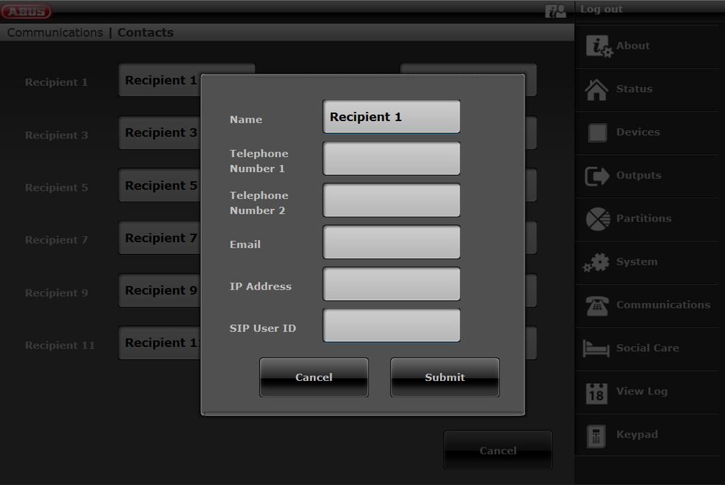
152 152
 will be assigned to sub-area 1.")
153 S/W >= The recipient can be assigned to sub-areas. This stipulates that the recipient will only receive a message when an event occurs in the specified sub-area. This assignment of sub-areas is only applicable to voice diallers, text messages and , and not for ARC/ESCC connection. Events not directly relating to a single sub-area (e.g. the double-key function on the alarm panel for fire, intrusion, medical emergency and care alarms) will be assigned to sub-area 1. Intrusion (remote control), intrusion (pendant), medical emergency (pendant) and care alarm (pendant). Events triggered by these user-controlled components are transmitted to the recipient where the selected sub-area matches the sub-area authorisation for that user. 153
154 Wireless control panel Double-key function for fire, intrusion, medical emergency and care alarms Events triggered by these components are transmitted to the recipient where the selected sub-area matches the assignment of sub-areas for that control device. SIP user ID Format S/W >= Phone number ID, if the recipient has an account with the same SIP service provider S/W < Phone number sipgate.de is the individual SIP service provider, as SIP server name ID, if the recipient has an account with the same SIP service provider 154
155 Nursing emergency call Name/function Start Monitoring Hr End Monitoring Hr Monitoring Interval Language Volume Explanation (checkbox) Start time of social care monitoring (hh:mm). End time of social care monitoring (hh:mm). Interval in hours. Volume of voice announcement. 155

156 Test Select the corresponding function. Via web interface with S/W >= An overview of the different functions can be found in the table below. Test call to external recipients. Please inform them in advance and let them know that it is just a test call. Test call e.g. receiving centre, language call, SMS, . Role Walk Test Meaning Bell On: An info tone sounds when a detector is operated. Off: No info tone sounds. All detectors belonging to the system can be tested here. The zones can be individually selected during test. Activate all detectors in the building one after the other. If a detector is triggered the alarm panel emits two signal tones The Alarm column will display whether a detector has detected an alarm. The tamper column will display whether a tamper contact has been triggered. 156

. When all detectors have been tested the system writes \"All Zones tested\".")
157 Walk test (cont.) Report The test results can also be printed out and saved via the web interface. Alarm panel System All detectors belonging to the system can be tested here. Activate all detectors in the building one after the other. If a detector is triggered the alarm panel emits two signal tones It also indicates on the display whether a tamper contact (S) and/or alarm (A) was triggered. The top of the display shows the number of zones still to be tested (alarm and tamper). When all detectors have been tested the system writes "All Zones tested". Partitions Detectors from a specific partition can be tested here. Once the partitions are selected only the detectors in the selected partitions are displayed. Zones Selected detectors can be tested here. A list of all detectors appears. Select the detectors to be tested with Yes. 157
158 Role Keypad Meaning Testing the keypad is possible both on the alarm panel and the web interface. Press all buttons on the keypad one after the other. The corresponding character or button function is shown on the display in response. Press the dual keys (fire alarm, hold up alarm, medical emergency or social care alarm) at the same time to test them. The function of the key combination is shown on the display in response. S/W >= Press the dual keys for the cleaning mode (left and right menu keys) simultaneously to test. The function of the key combination is shown on the display in response. Cleaning mode will not be carried out. You can find instructions for cleaning mode in the user guide. Sirens & Sounders Testing of sirens and sounders is carried out in the web interface in the same manner as on the alarm panel. Int.Sirens The sounders on the alarm panel, info module, indoor siren and wireless control device are actuated. Ext. Radio Sirens The sounders for the wireless external sirens are actuated. Sounder Module The sounders for the external sirens are actuated. External siren in connection with the wireless universal module (WUM) as a "Sounder Module". Loudspeaker Select "Play/Stop" to hear all existing messages in the system one after the other. 158

159 Role Meaning Wireless control panel Testing of wireless control panels is carried out in the web interface in the same manner as on the alarm panel. Press the function buttons on the wireless control device one after the other. Wait 2 to 3 seconds between each button so that the control device can send each message. A corresponding letter appears on the display in response: A = "arm" button (closed lock) C = "internal arm" button (*) D= "query status" button (?) B = "disarm" button (open lock) On the Web you will also see: Arm system key Arm system internally key Status query Disarm system key To test the number buttons, press 4 or 6 numerical buttons (corresponding to the set code length) and then a function button: Example: Press : 1234? Displayed : 1234D (status query) Press the dual keys (fire alarm, hold up alarm, medical emergency or social care alarm) at the same time to test them. On the display: F = dual keys fire alarm P = dual keys hold up M = dual keys medical emergency H = dual keys social care alarm On the Web you will also see: Fire key Intrusion key Medical emergency call key Social Care Key The lower "*" and "#" button on the control device cannot be tested. 159
160 Role Door locks Meaning Testing of door locks is carried out in the web interface in the same manner as on the alarm panel. Select the door lock to be tested. Operate the corresponding door lock. After unlocking, "Unlocked" appears on the display. After locking, "Locked" appears on the display. Secvest key: press the button and then lock. Additional door lock: do not press the button. Then lock. Signal Strengths You can check here whether DIP switch 3 in the Secvest key is correctly set according to the door stop. The received signal strength is also displayed. The meaning of the number before and inside the brackets can be found in the signal strength explanation. This option can be used to check the received signal strengths of all wireless components of the system. To ensure good wireless communication, you must have a signal strength greater than 3. During the test, the reception power of the wireless alarm panel is reduced by 6 db. The Secvest wireless alarm panel is sensitive to approx dbm at a signal-tonoise ratio of 12 db. The following level values apply for the signal strength display on the Secvest: 0 < 101 dbm 1 < 98 dbm 2 < 95 dbm 3 < 92 dbm 4 < 89 dbm 5 < 86 dbm 6 < 83 dbm 7 < 80 dbm 8 < 77 dbm 9 77 dbm The number before the brackets is the signal strength of the last received signal. The number inside the brackets is the smallest signal strength received since the last reset. The alarm panel records the received signal strengths, even if you do not see them in this menu. S/W < The signal strength of the repeated signal from the WAM is the same as that from each WAM. For this reason, use the display of the signal strength for the corresponding WAM in order to gain information about the signal strength of the repeated signals from the wireless components. S/W >= The signal strength of the direct signal from each component is displayed in the right-hand column (WEB column direct). The signal strength of the repeated signal from the WAM or the RF repeater is displayed in the left-hand column (WEB column repeater). 160
161 Resetting signal strengths to begin a new measurement. WEB Click on the line for the desired component and follow the instructions on the screen. Click on Reset ALL and follow the instructions on the screen. This will clear the recorded signal strengths for the entire list. Alarm panel # key Press this key to delete the recorded signal strengths for the selected component. * key Press this key to delete the recorded signal strengths for the entire list. Signal strengths (cont.) Detectors The display shows the signal strength of each taught-in detector. S/W < The zone names are displayed. To view the zone numbers, press the right menu key Wireless control panel The display shows the signal strength of each taught-in control device. External Sirens The display shows the signal strength of each taught-in wireless external siren. WAM The display shows the signal strength of each taught-in WAM. Door locks The display shows the signal strength of each taught-in door lock. RF repeater (only alarm panel) The display shows the signal strength of each taught-in RF repeater. Under RF repeater below you will find clarifications for the display on the WEB. RF repeater components (only alarm panel) The display shows the signal strength of each assigned component to each RF repeater on the RF repeater. Under RF repeater below you will find clarifications for the display on the WEB. Repeat alarm panel You can find the signal strength of the received messages from the alarm panel on the repeater here. Repeat detectors You can find the signal strength of the received messages from the detectors on the repeater here. Repeat wireless control panel You can find the signal strength of the received messages from the wireless control panel on the repeater here. Repeat external sirens You can find the signal strength of the received messages from the external sirens on the repeater here. 161
162 Repeat door locks You can find the signal strength of the received messages from the door locks on the repeater here. Outputs Prox Tag Radio Outputs Use this option to check all configured radio outputs. Wired Outputs Use this option to check all configured wired outputs. After exiting the menu, all outputs switch back to their basic configured state. Testing of chip keys is carried out in the web interface in the same manner as on the alarm panel. Move the Prox Tag across the reader area at the bottom of the alarm panel (where the ABUS logo is). The following information appears on the display: which user is assigned to this Prox Tag or that the Prox Tag is not recognised by the alarm panel. 162
163 Role Remote controls Emergency buttons Meaning Testing of the remote control is carried out in the web interface in the same manner as on the alarm panel. Press a button on the remote control. The following information appears on the display: the consecutive number of the remote control a letter or character corresponding to the pressed key A = "arm" key (closed lock) * = "internally arm" key or key for activating a "User Defined" output (*)? = "query status" key (?) D = "disarm" key (open lock) which user is assigned to this remote control the function of the pressed button - Set All - Prt Set All or Output On (Off or Toggle) xyz - Query Status - Unset All the received signal strength (RSSI) Example Remote 001,D:User 002 Complete disarming RSSI: 9 Testing of the remote control is carried out in the web interface in the same manner as on the alarm panel. Press the button on a pendant. The following information appears on the display which user is assigned to this emergency button the function of this pendant HUA = hold up alarm Medical = medical emergency PFN alarm = social care alarm the received signal strength (RSSI) Example User: User 002 Func: Medical RSSI: 9 163
164 Role ARC reporting Meaning Testing of the ARC reporting function is carried out in the web interface in the same manner as on the alarm panel. ARC Reporting must be activated and the contact must be saved in the phone book. Installer Mode->Communications->ARC Reporting ->Call Mode ->Single (or Alternate) A list of the available connected transmission paths can be seen: Ethernet When this is selected, the 2 possible configured recipients (IP Recipient 1, IP Recipient 2) are displayed with their contact names as stored in the phone book. Scroll to the desired contact. Press the "Select or Start key in the web interface. The alarm panel sends a test call to this recipient. The event (or trigger) "Test" is sent according to the set protocol. PSTN When this is selected, the 2 possible configured recipients (Tel Recipient 1, Tel Recipient 2) are displayed with their contact names as stored in the phone book. Scroll to the desired contact. Press the "Select or Start key in the web interface. The alarm panel sends a test call to this recipient. The event (or trigger) "Test" is sent according to the set protocol. GSM When this is selected, the 2 possible configured recipients (Tel Recipient 1, Tel Recipient 2) are displayed with their contact names as stored in the phone book. Scroll to the desired contact. Press the "Select or Start key in the web interface. The alarm panel sends a test call to this recipient. The event (or trigger) "Test" is sent according to the set protocol. During the test call a series of progress messages appear on the display. If the test call was not successful, the display shows a brief message with the cause of the error. 164
165 Role Nursing emergency call Meaning Testing of the nursing emergency call function is carried out in the web interface in the same manner as on the alarm panel. Nursing emergency call must be activated and the contact must be saved in the phone book. Installer Mode->Communications->ARC Reporting ->Call Mode ->Single (or Alternate) A list of the available connected transmission paths can be seen: PSTN When this is selected, the 2 possible configured recipients (Tel Recipient 1, Tel Recipient 2) are displayed with their contact names as stored in the phone book. Scroll to the desired contact. Press the "Select or Start key in the web interface. The alarm panel sends a test call to this recipient. The event (or trigger) "Test" is sent according to the set protocol. GSM When this is selected, the 2 possible configured recipients (Tel Recipient 1, Tel Recipient 2) are displayed with their contact names as stored in the phone book. Scroll to the desired contact. Press the "Select or Start key in the web interface. The alarm panel sends a test call to this recipient. The event (or trigger) "Test" is sent according to the set protocol. During the test call a series of progress messages appear on the display. If the test call was not successful, the display shows a brief message with the cause of the error. 165
166 Role Voice dialler Meaning Speech Dialler must be activated. Installer Mode->Communications->Speech Dialler->Call Mode->Enabled A list of the available connected transmission paths can be seen: Ethernet When this is selected, enter a valid SIP User ID. e.g @sipgate.de Press the "OK" button. The alarm panel establishes a connection. If the call is answered by this recipient, the recipient hears the "Home Message" and "Message 1" to "Message 4". S/W >= When this is selected, the configured recipients are displayed with their contact names as stored in the phone book. Scroll to the desired contact. Press the "Select or Start key in the web interface. The alarm panel sends a test call to this recipient. PSTN When this is selected, enter a number to dial. Press the "OK" button. The alarm panel establishes a connection. If the call is answered by this recipient, the recipient hears the "Home Message" and "Message 1" to "Message 4". S/W >= When this is selected, the configured recipients are displayed with their contact names as stored in the phone book. Scroll to the desired contact. Press the "Select or Start key in the web interface. The alarm panel sends a test call to this recipient. GSM When this is selected, enter a number to dial. Press the "OK" button. The alarm panel establishes a connection. If the call is answered by this recipient, the recipient hears the "Home Message" and "Message 1" to "Message 4". S/W >= When this is selected, the configured recipients are displayed with their contact names as stored in the phone book. Scroll to the desired contact. Press the "Select or Start key in the web interface. The alarm panel sends a test call to this recipient. If "Call Acknowledge" is activated: The recipient can acknowledge and end the call with 5 or 9 respectively if the following is set: Installer Mode->Communications->Speech Dialler->Call Acknowledge ->Enabled. During the test call a series of progress messages appear on the display. If the test call was not successful, the display shows a brief message with the cause of the error. SMS Text messages must be activated and the contact must be saved in the phone book. Installer Mode->Communications->SMS->Call Mode->Enabled 166
167 A list of the available connected transmission paths can be seen: PSTN When this is selected, the possible configured recipients are displayed with their contact names as stored in the phone book. Scroll to the desired contact. Press the "Select or Start key in the web interface. The alarm panel sends a test text message to this recipient. GSM When this is selected, the possible configured recipients are displayed with their contact names as stored in the phone book. Scroll to the desired contact. Press the "Select or Start key in the web interface. The alarm panel sends a test text message to this recipient. The recipient receives an SMS in the following form: <Home Message>: 10:56 21/01/2015 SMS Test Call During the test call a series of progress messages appear on the display. If the test call was not successful, the display shows a brief message with the cause of the error. must be activated and the contact must be saved in the phone book. Installer Mode->Communications-> ->Call Mode->Enabled When this is selected, the possible configured recipients are displayed with their contact names as stored in the phone book. Scroll to the desired contact. Press the "Select or Start key in the web interface. The alarm panel sends an to this recipient. The recipient receives an in the following form: Subject: <Home Message>: Test Call Text: <Home Message>: 11:09 21/01/2015 Test Call During the test call a series of progress messages appear on the display. If the test call was not successful, the display shows a brief message with the cause of the error. 167

168 Role Zone Resistances Meaning The current resistances for the wired zones are displayed here. Display on the alarm panel: The zone names are displayed. To view the zone numbers, press the right menu key. Test all variants according to the type of wiring to determine whether they meet the requirements: Alarm contact open/closed Tamper contact open/closed Short circuits Open (isolated circuits) 0k00 means 0 ohms or NC For wiring type "4-wire CC" the display switches between the resistance of the alarm loop (A) and the resistance of the tamper loop (S). Example for a "2-wire FSL 2K2/4K7" zone Alarm contact closed (standby) Alarm contact open Alarm contact open and series resistor bridged Short circuit in line to detector Line disconnection 2k18 6k89 4k68 0k00 NO Panel PSU Here you can find information about the voltage values of the power supply. The display is identical on the alarm panel and the web interface. Ext. DC voltage in The voltage value of the external DC power source Panel Battery 1 The voltage value of the first battery Panel Battery 2 The voltage value of the second battery Aux. Voltage Out The voltage value at the terminal clamp 0 V/12 V AUX Example (battery 2 is not connected in this example) Ext. DC voltage in 14.1 volts Panel Battery volts Panel Battery volts Aux. Voltage Out 13.9 volts 168
169 RF repeater Here you can find information about the signal strength of the components on the repeater. This is the signal strength on the repeater of the received notifications from the components. The display is identical on the alarm panel and the web interface Click on the line of the desired repeater. The following display then appears: Click on the desired component type. Details on the signal strength display can be found above under Test -> Signal Strengths. 169
170 Repeat alarm panel Here you can find 2 displays RF repeater This is the signal strength of the repeater to the alarm panel. Repeat alarm panel This is the signal strength of the alarm panel on the repeater. Both signal strengths are approximately the same. However, the signal strengths alarm panel -> repeater and repeater -> alarm panel can deviate slightly from each other. The reasons for this are: different antennas on the alarm panel and repeater different radio wave propagation characteristics in the different directions Repeat detectors You can find the signal strength of the received messages from the detectors on the repeater here. 170
171 Repeat wireless control panel You can find the signal strength of the received messages from the wireless control panel on the repeater here. Repeat external sirens You can find the signal strength of the received messages from the external sirens on the repeater here. Repeat door locks You can find the signal strength of the received messages from the door locks on the repeater here. 171
.")
172 Log You can view the "log book" in this menu. The log book contains all of the relevant data for the alarm panel including the date and time. The memory can hold up to 600 entries. If the memory is full, the oldest entry is deleted and overwritten with the new entry (FIFO principle: first in, first out). You can find an overview of the possible log entries in the appendix. 172

173 Virtual keypad The virtual keypad has all the functionality of the keypad and display of the alarm panel. On the alarm panel you press the corresponding buttons. On the virtual keypad, you click the corresponding buttons using the mouse. The displays on the virtual keypad are the same as those on the alarm panel. the following: If you are logged in as an installer on the web server, you open the virtual keypad in installer mode after entering an installer code. If you are logged in as a user/administrator on the web server, you open the virtual keypad in the user menu after entering a user code. 173
174 Appendix Appendix Technical data General Product name Secvest Product description Wireless alarm system Manufacturer ABUS Security-Center GmbH & Co. KG Environmental class II (EN A1:2009 Section 7, EN Section 7) Protection class IP34 (indoor) Operating temperature 0 C to 40 C Humidity, maximum Non-condensing average relative humidity 75% Housing material ABS Dimensions (W x H x D) 205 x 285 x 48 mm Weight 1453 g (excluding batteries) 1543 g (including one battery) 90 g one battery Capacity Zones IP zones 3 6 (S/W and later) for the ABUS camera models specified see the appendix to the instructions for installers entitled "Compatible equipment" Wireless Zones 48 Wired Zones 4 (2-wire FSL/DEOL or 2-wire CC) 2 (4-wire CC) Wireless control panels 8 External Sirens Wireless sirens 4 Wired sirens 1 Info modules/internal sirens WAM 8 Door locks 8 RF repeater 4 Number of components per repeater 10 Remote controls and emergency transmitters (intrusion, medical emergency, care alarm) are always repeated. Outputs IP Outputs 0 Radio Outputs 32 Wired Outputs 4 Partitions Four (each with internal arming) User 50 User names 50 (plus installer name) User Codes 50 (plus installer code) Proximity tags (chip keys) 50 (one per user) Remote controls 50 (one or several per user) Panic alarm transmitter 50 (one per user) 174
175 Appendix Medical emergency call transmitter Nursing emergency call transmitter 50 (one per user) 50 (one per user) Telephone book 12 contacts Name 2 telephone nos 1 1 IP address 1 VoIP/SIP ID Calendar timers enabled/disabled 10 time schedules each with 16 events 20 exceptions Logbook capacity Up to 600 events 500 mandatory events 100 non-mandatory events Stored in EEPROM storage (non-volatile memory NVM) retained for at least ten years without electricity. The whole log book stores its records for at least ten years without electricity. : The logbook is protected and cannot be deleted by an installer, administrator or ordinary user. Internal clock 1 Loudspeaker 1 Microphone 1 Voice messages 33 voice messages for each language installed on the alarm panel 5 messages recorded by the user (Installer mode voice dialler) 12 second site message 8 seconds for each message memo message (user menu) 30 seconds 58/56 zone names (user menu) 2 seconds for each zone 6 IP zones 48 wireless zones 4/2 wired zones Internal Siren 1 (integrated piezo sounder) Sound pressure level > 96 1 m Communication modules, plug-in 1 Ports 1x Ethernet 1x a/b 1x USB 1x SD card Backup batteries 2 Display 3.5", effective area 84 mm x 45 mm, 240 x 128 pixel monochrome (greyscale) LCD, white backlighting 175
176 Appendix Protection and security Security level Level 2 (EN A1:2009 Section 6, EN Section 6) Environmental class II (EN A1:2009) Tamper protection (detection/protection) Type B (EN Section 8.7) Wireless components, differentiation 16,777,214 (2 24-2) different IDs per component type Wireless supervision Configurable Access codes There is no default installer code. There is no default administrator code. S/W <= It is absolutely essential to change the default code (administrator user code: 1234 or ) during installation. Quantity of access codes 50 plus one installer Access code differentiation 10,000 code variants with 4-digit codes ( ) The digits of the code are numbers between 0 and = 10x10x10x10 = 10,000 (combinatorial variation) 1,000,000 code variants with 6-digit codes ( ) The digits of the code are numbers between 0 and = 10x10x10x10x10x10 = 1,000,000 (combinatorial variation) Quantity of proximity tags 50 (chip keys) Proximity tag differentiation 4,294,967,296 (2 32, 2^32) Temporary authorisation for user access There is no facility for providing temporary access (e.g. PIN code or proximity keyfob which is only valid for a limited time or a specified quantity). Locking access/locking codes Mechanical keys Control panels Door locks Wireless key switch Mechanical key differentiation 30,000 Additional door lock Secvest Key Web user name length Mechanical key differentiation 30,000 Mechanical key differentiation Keyboard is locked for 5 minutes after 3 incorrect codes in succession. Keyboard is locked for 5 minutes after 3 incorrect proximity keyfobs in succession. FUBE50060, FU8165 FUFT , 7010E 7025E FUSK , FUBE5XXXX 12 characters Web user name differentiation (215,671,155,821,681,003,462,656, 88^12, >1,000,000) All characters can be alphanumeric symbols or special symbols. A-Z 26 a-z
177 Appendix Space apostrophe 14 Æ Å Ä Ø Ö Ü (upper case) 6 Æ Å Ä Ø Ö Ü (lower case) 6 88 Web encryption HTTPS SSL version 3/TLS 1.2 < 2.0.0: Signature algorithm: SHA1 >= 2.0.0: Signature algorithm: SHA256 (SHA 2) Electromagnetic compatibility EMC immunity Electromagnetic compatibility EMC interference Electrical safety Complies with EN Complies with EN Complies with EN Power supply Type of power supply Type A (EN Section 9 and EN Section 4.1) Secvest has an integrated power supply unit (Type A). This power supply unit supplies different internal voltages to the circuit board to supply power to the circuitry. This power supply unit supplies 13.8 V with a maximum of 700 ma at the 0 V/12 V AUX output. Normal voltage/frequency Power consumption, maximum Power consumption, nominal External DC input fault triggered at External PSU Power consumption, typical 110 V/230 V AC, 50/60 Hz, ( V AC, 50/60 Hz) 13.8 V DC ( V DC) I AC MAX: 430mA 85VAC 190mA 230VAC 170mA 265VAC 6.9 W 6.9 W x 24 x 365 = 60 kwh per year 55mA 230VAC specified with 200 ma aux load and fully charged batteries V 12.5 V OK at 12.7 V V DC, at least 1.7 A Alarm panel standby: 100 ma Backlighting off Backlighting: High: 100 ma Medium: 40 ma Low: 15 ma 177
178 Appendix Internal siren sounding alarm at maximum volume: 70 ma GSM standby:15 ma GSM in use: 140 ma Battery charging current per battery: 220 ma Backup power supply Rechargeable battery Polymer lithium ion, 7.4 V Capacity 2500 mah, 18.5 Wh Minimum running time in emergency More than 12 hours power mode (standby time) More than 24 hours with optional second battery Maximum recharging time Less than 72 hours (EN Section 9 Table 24) Maximum time to recharge 24 hours) the battery to 80% Lower threshold value 7.2 V of the battery "Flat battery" fault at <7.2 V Deep discharge protection at 6 +/- 0.2 V Aux power supply output I max. 700 ma (main pcba issue < 7) I max. 600mA (main pcba issue >= 7) Running on the mains ( V AC, 50/60 Hz) 13.9 V max, idle 13.4 V min, full load (@ 700 ma) Running on DC 12.8 V max, idle 12.2 V min, full load (@ V max, idle 13.0 V min, full load (@ V max, idle 13.7 V min, full load (@ 700 ma) This output is not buffered by the battery in case of power failure. The output voltage during a power failure is directly 0 V. Aux power supply output fault triggered at 11.5V OK from 12.0 V Surge protection trip voltage Not given for grade 2 PSU monitoring Monitoring covers AC and external DC faults. It notifies the alarm panel if the AC or external DC power supply is disrupted or fails. The alarm panel will continue running on the batteries but the alarm panel and user are informed. Monitoring covers battery under voltage. If the battery is flat, the alarm panel and user are informed and the alarm panel gives a warning. 178
179 Appendix Fuses Mains fuse (AC in) Name Characteristic Operating current Breaking capacity Operating voltage Design Miniature fuse (micro fuse) removable T1AL250V T = slow blow 1 A L = low 250 V Glass tube 5x20 mm Wireless signal transmission Operating frequency Modulation Bandwidth Transmission power Sensitivity Signal-to-noise ratio Antenna Range Special features MHz In accordance with: EN Grade 2 EN V EN V EN V Frequency band reserved for applications in the security zone. FM +/- 10 khz Narrow band, 25 khz channel separation 10 mw approx. 110dBm 12dB Integrated duplex antenna technology Indoors: approximately 30 m depending on environmental factors Outdoors: approximately 100 m Individual identification Supervision monitoring Jamming detection RFID proximity keyfob reader Operating frequency Special features MHz In accordance with: EN Individual identification Connections L N Mains connection 110 V/230 V AC, 50/60 Hz, ( V AC, 50/60 Hz) L line, single phase (black or brown) - DC IN V protective earth (yellow/green) N neutral (blue) External PSU input 13.8 V DC, external PSU at least 1.7 A See Power supply section for more details 179
180 Appendix 0 V 12 V AUX Voltage output 13.8 V DC up to 700 ma, main pcba issue < 7 up to 600 ma, main pcba issue >= 7 Maximum output residual ripple (ripple voltage): 0.2 Vp-p Aux output fault triggered at 11.5 V, ok from 12.0 V See Power supply section for more details +BATT1,+BATT2 OP 301, OP 302 OP 303, OP 304 This output is not buffered by the battery in case of power failure. The output voltage during a power failure is directly 0 V. Battery polymer lithium ion, 7.4 V, 2500 mah Relay output Potential-free changeover contact NO/C/NC Max. contact capacity: V AC rms or 30 V DC Transistor output Open-drain Max. contact capacity: V DC These outputs will drop to 0 V during power failures TR A negative tamper input The input is switched to the inactive low state (ground potential) by the connected siren. The threshold voltages are > 4 V for active and < 3.6 V for inactive. TRB A negative fault input The input is switched to the inactive low state (ground potential) by the connected siren. The threshold voltages are > 4 V for active and < 3.6 V for inactive. 10/100 LAN Ethernet/LAN Cat5e patch cable, RJ45 male Connector at each end, suitable for 10/100Base-T USB TYPE-B USB Mini-B connector for alarm panel USB-A connector for PC Max. length 3 m A B Interface for analogue telephone connection to the public telephone network, a private branch exchange or an integrated access device (IAD [router] e.g. Vodafone Easybox xyz or FRITZ!Box vwxy) Approved for telecommunications in accordance with TBR- 21/CTR21 (ETSI ES203021) > 18 V REN rating 1 PSTN data rates up to 1200 bps (V.22) Micro SD Secure Digital Memory Card Micro SD 11 mm x 15 mm x 1.0 mm 4 GB Micro SDHC Z301, Z302, Z303, Z304 Wired Zones 2-wire FSL 2K2/4K7 2-wire FSL 1K/1K 2-wire FSL 2K2/2K2 2-wire FSL 4K7/4K7 2-wire CC 180
181 Appendix Z301A/Z301T, Z302A/Z302T Wired Zones 4-wire CC Resistance ranges specified for idle, alarm and tamper states (in Ohms). Resistances immediately by the screw terminals. Recommended cable resistance: must be less than 100 Ohms. 2-wire FSL 2-wire FSL 2-wire FSL 2-wire FSL 4K7/4K7 2K2/4K7 1K/1K 2K2/2K2 O/C tampering Alarm Idle S/C tampering wire CC 2-wire CC Open/alarm/tampering Closed/idle Communication Communication channels a/b interface Ethernet GSM Interface for analogue telephone connection to the public telephone network, a private branch exchange or an integrated access device (IAD) 10/100 LAN Plug-in module, optional Quad-band GSM: 850/900/1800/1900 MHz Communication methods Web server ARC/ESCC reporting Receiver Protocols Web access, app and ABUS server 2 Tel, 2 IP Analogue Fast Format, Contact ID, SIA 1, SIA 2, Ex SIA 3, Ex SIA 3 V2, CID in SMS IP DC-09 (SIA-IP), with Fast Format, Contact ID, SIA Protocol Token FF CID SIA 1, SIA 2, SIA 3, Ex SIA 3, Ex SIA 3 V2 SCN-S8 ADM-CID SIA-DCS TCP, unencrypted : For details, see the appendix to the instructions for installers entitled "ARC (ESCC) reporting protocol formats" 181
182 Appendix Nursing emergency call Receiver 2 Tel Protocols Scancom, Scanfast, Tunstall Voice dialler Receiver 8 Tel or VoIP/SIP ID DTMF detection VoIP/SIP RFC 2833 Acknowledgement Codec VoIP/SIP PCM G711 A law (RTP AV Profile 8) ITU-T G.711 PCM A-Law audio 64 kbit/s Reference RFC 3551 SMS Receiver 8 PSTN SMS protocols TAP 8N1 TAP 7E1 UCP 8N1 UCP 7E1 ETSI Protocol 1 Receiver 8 Remote control by telephone ATS Alarm transmission system Categories and classifications ATS (Alarm Transmission System) categories, SPT (Supervised Premises Transceiver) classification Classification of transmission time Transmission time, maximum values Classification of notification time Classification of availability Security to prevent removal Information security Monitoring a/b, Ethernet and GSM Handshaking procedure Yes The alarm panel contains an integrated SP2 (ATS2) communicator to fulfil the requirements of EN50131 for security grade 2. The alarm transmission system is compliant with EN :2012 as an SP2 (ATS2) communicator. The alarm panel supports options A, B and C for grade 2 as given in Table 10 in EN :2006+A1:2009. D2 -> SP2 M2 -> SP2 T2 -> SP2 A0 (no requirement)-> SP2 (optional) There is no method for achieving compliance with EN :2012, (non-availability of the alarm transmission system) because A0, no requirement. S0 (no measures) -> SP2 (optional) There is no method for achieving compliance with EN :2012, (redundancy) because S0, no measures I0 (no measures) -> SP2 (optional) There is no method for achieving compliance with EN :2012, (information security) because I0, no measures. See the Communication options chapter in the Installer manual. Installer mode -> Communication -> Comm. options -> Comm. path fault response Ethernet, PSTN (a/b), GSM Installer mode -> Communication -> Comm. options -> Comm. path fault delay Ethernet, PSTN (a/b), GSM Mode/procedure: Transfer (EN Section 6, Operation) 182
183 Appendix Other Configuration Web browser via the integrated web server or directly on the alarm panel Declarations of compliance for the FUAA50000, FUAA50010, FUAA50100 and FUAA50110 Secvest wireless alarm panel systems Standards with which the alarm panel claims compliance EN :2006+A1:2009 EN :2009 EN :2005+A1:2008 EN :2008+A1:2014 EN :2014 EN :2013 INCERT TO edition Security level: Level 2 Environmental class: Class II If the alarm panel has been installed correctly, the Secvest will be compliant with EN50131 Grade 2. The Secvest is compliant with EN and EN environmental class II. Power supply is compliant with EN :2006+A Section 9 and EN if the alarm panel has been installed correctly. The alarm transmission system (integrated SP2 [ATS2] communicator) is compliant with EN :2012 as an SP2 (ATS2) communicator. At Grade 2 the integrated SP2 (ATS2) communicator provides a compliant communicator for the Secvest on the condition that a) it is installed as specified in the installation instructions b) the connected PSTN, LAN and GSM work normally c) the alarm receiving centre has the right equipment. The FUMO5000X GSM module can be used as a supplementary communicator for Grade 2. The alarm panel supports options A, B and C for grade 2 as given in Table 10 in EN :2006+A1:2009. If the installer selects a non-compliant configuration the compliance label must be removed or corrected. Third party verification of compliance was carried out by ANPI. 183
184 Appendix Compatible equipment Radio devices Name Article no Detectors Opening detector CC (brown) Opening detector CC (white) Opening detector FSL (brown) Opening detector FSL (white) Additional door lock with rotary knob 7010 E (brown) Additional door lock with rotary knob 7010 E (silver) Additional door lock with rotary knob 7010 E (white) Additional door lock with rotary knob 7010 E (brown) Additional door lock with rotary knob 7010 E (silver) Additional door lock with rotary knob 7010 E (white) Additional door lock with inner cylinder 7025 E (brown) Additional door lock with inner cylinder 7025 E (silver) Additional door lock with inner cylinder 7025 E (white) Additional door lock with inner cylinder 7025 E (brown) Additional door lock with inner cylinder 7025 E (silver) Additional door lock with inner cylinder 7025 E (white) Mini opening detector (brown) Mini opening detector (silver) Mini opening detector (white) Narrow opening detector (white) Window lock FTS 96 E AL0089 (brown) Window lock FTS 96 E AL0089 (white) Window lock FTS 96 E AL0125 (brown) Window lock FTS 96 E AL0125 (white) Window lock FTS 96 E AL0145 (brown) Window lock FTS 96 E AL0145 (white) Upgrade kit for FTS 96 (brown) Upgrade kit for FTS 96 (white) Window handle FG 350 E (brown) Window handle FG 350 E (silver) Window handle FG 350 E (white) Window bar lock FOS 550 E AL0089 (brown) Window bar lock FOS 550 E AL0089 (white) Window bar lock FOS 550 E AL0125 (brown) Window bar lock FOS 550 E AL0125 (white) Window bar lock FOS 550 E AL0145 (brown) Window bar lock FOS 550 E AL0145 (white) Upgrade kit for FOS 550 E AL0089 (brown) Upgrade kit for FOS 550 E AL0089 (white) Upgrade kit for FOS 550 E AL0125 (brown) Upgrade kit for FOS 550 E AL0125 (white) Upgrade kit for FOS 550 E AL0145 (brown) Upgrade kit for FOS 550 E AL0145 (white) Window handle lock FO 400 E AL0089 (brown) Window handle lock FO 400 E AL0089 (white) Window handle lock FO 400 E AL0125 (brown) Window handle lock FO 400 E AL0125 (white) FUMK50000B FUMK50000W FUMK50010B FUMK50010W FUFT50010B FUFT50010S FUFT50010W FUFT50011B FUFT50011S FUFT50011W FUFT50020B FUFT50020S FUFT50020W FUFT50021B FUFT50021S FUFT50021W FUMK50020B FUMK50020S FUMK50020W FUMK50030W FUFT50000B FUFT50000W FUFT50001B FUFT50001W FUFT50002B FUFT50002W FUFT50008B FUFT50008W FUFT50040B FUFT50040S FUFT50040W FUFT50030B FUFT50030W FUFT50031B FUFT50031W FUFT50032B FUFT50032W FUFT50036B FUFT50036W FUFT50037B FUFT50037W FUFT50038B FUFT50038W FUFT50050B FUFT50050W FUFT50051B FUFT50051W 184
185 Appendix Upgrade kit for FO 400 FUFT50058 PIR motion sensor FUBW50000 Motion detector (PET) FUBW50010 Outdoor motion detector FUBW50020 FUBW50021 FUBW50022 Smoke alarm device FURM50000 Glass breakage detectors FUGB50000 Shock detector FUEM50000 Flood detector FUWM50000 Panic alarm button FUAT50010 Hold up detector Fire alarm button FUAT50020 Control panels Control panel FUBE50000 Activate/deactivate (arming/disarming) Control panel with RC FUBE50001 Activate/deactivate (arming/disarming) S/W >= V Key switch FUBE50060 Activate/deactivate (arming/disarming) Key switch with RC FUBE50061 Activate/deactivate (arming/disarming) S/W >= V External Sirens Outdoor siren Outdoor siren Info modules/internal sirens Information module Indoor siren WAM Wireless universal module (WUM) FUSG50000 FUSG50100 FUMO50030 FUSG50010 FUMO50020 Door locks Additional door lock with rotary knob 7010 E (brown) FUFT50010B Activate/deactivate (arming/disarming) Additional door lock with rotary knob 7010 E (silver) FUFT50010S Activate/deactivate (arming/disarming) Additional door lock with rotary knob 7010 E (white) FUFT50010W Activate/deactivate (arming/disarming) Additional door lock with rotary knob 7010 E (brown) with RC Additional door lock with rotary knob 7010 E (silver) with RC Additional door lock with rotary knob 7010 E (white) with RC FUFT50011B FUFT50011S FUFT50011W Activate/deactivate (arming/disarming) S/W >= V Activate/deactivate (arming/disarming) S/W >= V Activate/deactivate (arming/disarming) S/W >= V Additional door lock with inner cylinder 7025 E (brown) FUFT50020B Activate/deactivate (arming/disarming) 185
186 Appendix Additional door lock with inner cylinder 7025 E (silver) FUFT50020S Activate/deactivate (arming/disarming) Additional door lock with inner cylinder 7025 E (white) FUFT50020W Activate/deactivate (arming/disarming) Additional door lock with inner cylinder 7025 E (brown) with RC Additional door lock with inner cylinder 7025 E (silver) with RC Additional door lock with inner cylinder 7025 E (white) with RC FUFT50021B FUFT50021S FUFT50021W Activate/deactivate (arming/disarming) S/W >= V Activate/deactivate (arming/disarming) S/W >= V Activate/deactivate (arming/disarming) S/W >= V Secvest key FUSK5xxxx Activate/deactivate (arming/disarming) Secvest key with RC FUKE Activate/deactivate (arming/disarming) S/W >= V RF repeater Repeater module Secvest FUMO50010 S/W >= V Outputs Socket FUHA50010 Prox Tag Proximity keyfob FUBE50020 Activate/deactivate (arming/disarming) Remote controls Remote control Remote control with RC FUBE50010 FUBE50011 FUBE50012 FUBE50013 FUBE50014 FUBE50015 Activate/deactivate (arming/disarming) Activate/deactivate (arming/disarming) S/W >= V Hold up pendant Emergency buttons FUAT50000 Panic alarm button: Medical emergency call transmitter Emergency buttons Nursing emergency call transmitter Emergency buttons Test devices Test box FUAT50000 FUAT50000 FU
187 Appendix Wired components, accessories Name Article no IP cameras PIR network camera Outdoor IP Mini Dome IR 1080p TVIP41550 IPCB42500 IPCB42501 S/W >= V Outdoor IP Mini Dome IR Wi-Fi 1080p IPCB42550 S/W >= V Universal IP Dome IR 720p IPCB71500 S/W >= V Universal IP Mini Tube IR 1080p IPCB62500 S/W >= V Universal IP Dome IR 1080p IPCB72500 S/W >= V IPCB72501 Internal IP Dome IR 3MPx IPCA33500 S/W >= V Outdoor IP Dome IR Ultra Low-Light 1080p IPCA72520 S/W >= V Outdoor IP Dome IR 3MPx IPCA73500 S/W >= V Outdoor IP Dome IR 6MPx IPCA76500 S/W >= V Outdoor IP Tube IR Ultra Low-Light 1080p IPCA62520 S/W >= V Outdoor IP Tube IR 3MPx IPCA63500 S/W >= V Outdoor IP Tube IR 6MPx IPCA66500 S/W >= V Universal IP Boxtype 3MPx IPCA53000 S/W >= V Ultra-Low-Light IP Dome IR 1080p IPCS72520 S/W >= V Ultra-Low-Light IP Tube IR 1080p IPCS62520 S/W >= V Communication devices GSM module FUMO50000 GSM module FUMO50001 S/W >= V GSM antenna AZ6310W Default SIM card Standard SIM 1.8 V/3.0 V WiFi adapter FUMO50040 Ethernet <-> WiFi External PSU Power supply unit 13.8 V/1.7 A Backup power supply Backup battery 7.4 V/2500 mah AZZU10000 AZZU10030 FU3819 FUBT50000 SD card Micro SD 4 GB storage card TVAC GB Micro SDHC Touch Cover Individual Secvest Touch Cover FUZU50000 S/W >= Wired components that fulfil the electrical specification of the corresponding connections (zones, outputs, inputs). 187
188 Appendix Software for operation, control and communication Name Article no Browser IE8 Firefox Chrome Safari IE7 and older are NOT compatible App Secvest APP (ios) APP50000 Version ios 6.1 or later iphone, ipad, ipod touch Secvest APP (Android) APP50200 Version Android 4.0 or later Update S/W Secvest Update Utility Version or later 188
189 Appendix Default values/factory defaults The Secvest alarm control panel meets the requirements of EN50131 if the default values are retained while taking the note into account. If you change these settings, the installation may no longer be compliant. If the Secvest alarm control panel is no longer compliant with EN30131, you must remove all markings suggesting it is compliant. Installer Mode MENU option 1. COMPONENTS Default settings Default values Comments Detectors IP zones Add/Del Detectors Zone 1nn Zone 101 to 103 Zone 101 to 106 (S/W and Device Type IPCx Range Trigger Mode External Trigger Events No Only appears if Trigger Mode = "External" or "Int. + Ext." Camera Action Videos No Pictures Yes Trigger Partitions Sub-area 1 Yes IP address HTTP Port Internal 80 RTSP Port Internal 554 HTTP Port External Sub-area 2 Sub-area 3 Sub-area 4 All partitions Empty Empty Yes Yes Yes Yes later) Only appears if Trigger Mode = "External" or "Int. + Ext." RTSP Port External Empty User name Empty Password Empty Edit Zones Name Zone 10x Zone 101 to 103 Zone 101 to 106 (S/W Type Not used and later) Partitions None Only appears if the zone type is not set to "Not Used". 189
190 Appendix Attributes Delete All None Part Set Chime Soak Test Activity Mon. Force Set Omit Dis. Sabotage Omittable Inverted Off Off Off Off Off Off Off Off Only appears if the zone was given a type that was not "Not Used". Some attributes are only available for certain zone types. Wireless Zones Add/Del Detectors Zone 2nn Zone 201 to 248 Edit Zones Name Zone 2xy Zone 201 to 248 Not used Type Partitions None Only appears if the zone type is not set to "Not Used". Attributes None Only appears if the zone was given a type that was not "Not Used". Part Set Off Some attributes are only available Chime Off for certain zone types. Soak Test Off Activity Mon. Off Force Set Omit Off Dis. Sabotage Off Omittable Off Inverted Off Delete All Wired Zones Edit Zones Name Zone 30x Zone 301 to 304 Not used Type Partitions None Only appears if the zone type is not set to "Not Used". Attributes None Only appears if the zone was given a type that was not "Not Used". Part Set Off Some attributes are only available Chime Off for certain zone types. Soak Test Off Activity Mon. Off Force Set Omit Off Dis. Sabotage Off Omittable Off Inverted Off Delete All 190
191 Appendix Wireless control panel Add/Del Ctrl Dev Ctrl Dev 0n Ctrl Dev 01 to 08 Edit Ctrl Device Name Ctrl Dev 0x Ctrl Dev 01 to 08 Partitions Partition 1-4: Yes All partitions: Yes Part set Button C Instant Set Delete All Yes External Sirens Wireless sirens Add/Del Siren Wireless Siren 0n Wireless Siren 01 to 04 Edit Siren Name Wireless Siren 0n Wireless Siren 01 to 04 Partitions Partition 1-4: Yes All partitions: Yes Delete All Wired Sirens Wired SRN 01 Name Wired SRN 01 Indoor sirens/info module Add Panel Updates Ready-to-Set LED Disabled Disabled WAM Add/Del WAM WAM 0n WAM 01 to 08 Edit WAM Name WAM 0x WAM 01 to 08 Mode Delete All Door locks Add/Del Door Lock Door Lock 0n Door Lock 01 to 08 Edit Door Lock Name Door Lock 0x Door Lock 01 to 08 Partitions Partition 1-4: Yes All partitions: Yes Delete All 191
192 Appendix RF repeater Add/delete RF repeater RF repeater1 to 4 RF repeater1 to 4 Edit Door Lock Name RF repeater1 to 4 RF repeater1 to 4 No Repeat alarm panel Repeat detectors No After a repeater has been added, all taught-in detectors of the alarm Repeat wireless control panel No panel will appear. After a repeater has been added, all taught-in wireless control panels of the alarm panel will appear. Repeat external sirens No After a repeater has been added, all taught-in external sirens of the alarm panel will appear. Repeat door locks No After a repeater has been added, all taught-in door locks of the alarm panel will appear. Delete All 2. OUTPUTS Radio Outputs Add Outputs Output 2nn Output 201 to 232 Edit Outputs Name Output 2nn Output 201 to 232 Not used Type Polarity Normal Partitions Partition 1-4: Yes All partitions: Yes Delete All Wired Outputs Edit Outputs Name Output 3nn Output 301 to 304 Not used Type Polarity Normal Partitions Partition 1-4: Yes All partitions: Yes Delete All 3. PARTITIONS Partition 1-4 Name Partition n Partition 1 to 4 Complete arming Output Mode Timed Set Exit Time 40 seconds Only appears if the "Timed Set" or "Silent Set" Output Mode is set. 192
193 Appendix Settle Time 15 seconds Only appears if the "Final Door Set", "Lock Set" or "Cancel Exit Delay" Output Mode is set. Entry Time 40 seconds To fulfil EN Clause , maximum of 45 s Alarm Response Siren + Comms Internal alarm included Siren delay 0 minutes Ext. Siren Time 15 minutes 3 minutes when country = Germany To fulfil EN Clause 8.6, minimum 90 s, maximum 15 min. Strobe on Set Off This setting is required to fulfil EN Strobe on Unset Off Beep on Set Off This setting is required to fulfil Beep on Unset Int. Siren Time Off Endless EN Part set Output Mode Instant Set Exit Time 40 seconds Only appears if the "Timed Set" or "Silent Set" Output Mode is set. Settle Time 15 seconds Only appears if the "Final Door Set", "Lock Set" or "Cancel Exit Delay" Output Mode is set Entry Time 40 seconds To fulfil EN Clause , maximum of 45 s Alarm Response Siren Internal alarm included This setting is required to fulfil Siren delay Ext. Siren Time 0 minutes 15 minutes 3 minutes when country = Germany Final Door EN To fulfil EN Clause 8.6, minimum 90 s, maximum 15 min. Pt.Set Final Exit Pt.Set Entry Route Entry Route Strobe on Set Off This setting is required to fulfil EN Strobe on Unset Off Beep on Set Off This setting is required to fulfil Beep on Unset Int. Siren Time Off Endless EN Deactivated S/W >= Alarm Response Siren + Comms Internal alarm included Siren delay 0 minutes Ext. Siren Time 15 minutes Int. Siren Time 3 minutes when country = Germany Endless To fulfil EN Clause 8.6, minimum 90 s, maximum 15 min. 193
194 Appendix Panic response: Silent (S/W >= ) Acoustic (S/W < ) Full set link Sub-area 2-4: No All partitions: No Partition 1 is a common partition. 4. SYSTEM General Language German This value depends on how you answer the language question during Display Text Restore defaults Default settings Country defaults Secvest initial commissioning. Only appears as part of the factorydefault process. Mains Fault A/C Fault Reporting On This setting is required to fulfil EN A/C Fail delay 0 minutes This setting is required to fulfil EN Ext DC Fault reporting On This setting is required to fulfil EN Ext DC Fail delay 0 minutes This setting is required to fulfil EN Installer details Installer Name Installer Code Installer Tel No User access Record Memo Dual Key Function Social Care Key Omit All Yes No No Yes This value depends on how you answer the "Access Code Length" and "New Installer Code" questions during initial commissioning. This value depends on how you answer the "Access Code Length" and "New Installer Code" questions during initial commissioning. Quick Set No This setting is required to fulfil EN Quick Omit No User Code Req d Yes This setting is required to fulfil EN EN , Section (with reference to EN , Section 8.3.1) 2 Way Replies Yes Remote Inst. Set Yes Duress Enable No Switch to Yes for Duress Code use 194
195 Appendix User Reset Zone Alarms Yes This option only appears if the confirmation mode is set to "Basic". Zone Tampers Yes For INCERT detection, set to NO. System Tampers No Confirmation Confirmation mode Basic DD243 BS8243 Default for systems apart from the UK Default for UK systems if the UK is chosen as the country. This value depends on how you answer the "Country defaults" question during initial commissioning. This value depends on how you answer the "Country defaults" question during initial commissioning. Confirmation time 30 minutes Visible for DD243 or BS8243. Can be set to between 1 and 60 minutes. Ensure that only one value of 30 minutes or more is compliant with DD243 or BS8243. After Entry 1 Zone Visible for DD243 or BS8243. The default setting is changed to 2 zones if the confirmation mode = DD243. Entry Keypad Lock Off Visible for DD243 or BS8243. Sounder On Unconfirm Visible for DD243, BS8243 and Basic. Siren On Unconfirm Visible for DD243, BS8243 and Basic. Unconfirmed Reset User Visible for DD243 or BS8243. Confirmed Reset Installer Visible for DD243 or BS8243. Hold Up Alarm confirmation time 8 hours Only visible for BS8243. Must be between 8 and 20 hours to be compliant with BS8243:2010. Tamp as Tamp-Only Enabled Visible for BS8243. Hardware Wired Zone Type 2-wire FSL 2K2/4K7 This value depends on how you answer the "Wired Zone Type" RF Siren Options Battery 2 SD Card GSM antenna Security Supervision Jamming Siren + Strobe Disabled Internal Fault Tamper when country = UK Fault Tamper when country = UK Disabled question during initial commissioning. "TAMPER" for UK to fulfil PD6662:2010 "TAMPER" for UK to fulfil PD6662:2010 Remote Updates Tamper Omit Disabled This setting is required to fulfil EN Force Set Off If Force Set is enabled, the system Remote Unset Full Set Always is not compliant with EN
196 Appendix Remote Unset Part Set Always Ctrl Device Unset Full Set Always Ctrl Device Unset Part Always Set Auto Rearm Never This setting is required to fulfil EN Only appears if the confirmation mode is set to "Basic". Silence Alerts User Code Abort time 120 seconds Entry Alarm Delay Enabled This setting is required to fulfil Broadcast Panel Status Panel upgrade 5. COMMUNICATION No EN Network Network Setup Web server Enabled DHCP On IP address Empty This option will only be displayed, S/W>= DHCP=off IP Port Number 80 S/W < Internal HTTP port 80 Internal HTTPS port 4433 IP Subnet Mask Empty This option will only be displayed, S/W < if an IP address is entered. S/W>= DHCP=off Gateway IP address Empty This option will only be displayed, S/W < if an IP address is entered. DNS primary IP address Empty DYNDNS ABUS Server Status Enabled User name Empty Password Empty External Port 443 S/W < External HTTPS 4433 port Setup Server Name Empty Server IP port number 587 Account Empty User name Empty Password Empty S/W>= DHCP=off This option will only be displayed, S/W < if an IP address is entered. S/W>= DHCP=off 196
197 Appendix SSL Disabled VoIP Dialler Setup SIP Test Call Called SIP User Empty ID Start Test SIP Server Name Empty S/W < SIP domain name Empty SIP proxy Empty SIP user ID Empty SIP User Password Empty SIP Port 5060 RTP Port 4000 RFC 2833 DTMF Enabled Detection SIP Dialler Enable Enabled ARC reporting Call Mode Single "Single" or "Alternate" setting is required to be compliant with Protocol Telecoms Priority Ethernet 2 Fast Format PSTN 1 None Receiver Account Numbers Account number for sub-area 1: Account number for sub-area 2: Account number for sub-area 3: Account number for sub-area 4: Fast Format channels Channel 1: Fire Channel 2: Panic alarm Channel 3: Intruder alarm Channel 4: Open/Close Channel 5: Zone Omit (System) Channel 6: Tamper Activated Channel 7: Confirmed Alarm Channel 8: General Fault CID/SIA Events Fire Yes Panic alarm Medical Alarm Intruder alarm Technical Alarm Tampers Set/Unset Part set Reset Exit Timeout Yes Yes Yes No Yes Yes See 2 Yes See 2 Yes See 2 Yes EN One account number per partition Only appears if protocol = Fast Format s: 1. Appears if protocol = CID or SIA. 2. This setting is required to fulfil EN
198 Appendix Omit Key Box RF Supervision RF Jamming RF Battery/PSU Panel Battery Mains Fault Faults Installer Mode User Code Chnge Time/Date Reset Enabled Yes No Yes Yes See 2 Yes See 2 Yes See 2 Yes See 2 Yes See 2 Yes See 2 Yes No Restorals Burg Comms Rearm Enabled Only appears if protocol = Fast Format AND if confirmation mode = "Basic" 21CN Ack Time 800ms Only appears if protocol = Fast Format. Send Tamp As Burg Disabled Only appears if protocol = CID or SIA. Dynamic Test Call Enabled Only appears if Static Test Call disabled Static Test Call Disabled Only appears if Dynamic Test Call disabled. To be compliant with EN50131, either the static or dynamic test call must be Unset Comms Enabled Nursing emergency call Call Mode Disabled Protocol Scancom Telecoms Priority PSTN 1 Receiver None Account Numbers Account number for sub-area 1: Account number for sub-area 2: Account number for sub-area 3: Account number for sub-area 4: Enabled enabled. One account number per partition Call Acknowledge 21CN Ack Time 800ms Only appears if protocol = Scancom or Scanfast 198
199 Appendix Voice dialler Call Mode Disabled Telecoms Priority Ethernet 2 Messages Event Message 1 Message 2 Message 3 Message 4 Destinations Call Acknowledge PSTN 1 None None Event 1: None Event 2: None Event 3: None Event 4: None Event 5: None Event 1: None Event 2: None Event 3: None Event 4: None Event 5: None Event 1: None Event 2: None Event 3: None Event 4: None Event 5: None Event 1: None Event 2: None Event 3: None Event 4: None Event 5: None None Enabled SMS Call Mode Disabled Telecoms Priority PSTN 1 Messages Empty Event None PSTN SMS Protocol ETSI Protocol 1 Service Centre Tel. 1470, BT Own Telephone No Empty Only appears if protocol = UCP Destinations None Call Mode Disabled Telecoms Priority Ethernet 1 Messages Empty Event None Destinations None 199
200 Appendix Reporting Options Line Fail Response Line Fail Delay Ethernet = Audible PSTN = Audible GSM = Audible Ethernet = 9 seconds PSTN = 9 seconds GSM = 9 seconds This setting is required to fulfil EN GSM only visible if a GSM module is installed. Remote Control by Phone Call-out control Off Call-in control Off Rings to Answer 5 rings Only appears if Call-in control = on Answer on 1 ring Off Only appears if Call-in control = on GSM Omit Digit No Only appears when a GSM module is installed Contacts Recipient A-L Name Recipient A-L Partitions 1-4 S/W >= Empty Tel No 1 Tel No 2 IP address SIP user ID 6. NURSING EMERGENCY CALL Empty Empty Empty Empty Start Monitoring Hr End Monitoring Hr Monitoring Interval Volume 08:00 (hh:mm) 20:00 (hh:mm) 4 hours Alarm control panel medium, web 5 7. TEST Walk Test Keypad Sirens & Sounders Int.Sirens Ext. Wireless sirens Sounder Module Loudspeaker Wireless control panel Door locks Signal Strengths Detectors Wireless control panel External Sirens No Zones in use Off No Devices! No Devices! Stopped No Devices! No detectors No Devices! No Devices! 200
201 Appendix WAM Door locks RF repeater RF repeater components Outputs Radio Outputs Wired Outputs Prox Tag Remote controls Emergency buttons ARC reporting Ethernet PSTN No Devices! No Devices! No Devices! No Devices! No Outputs Available No Outputs Available No Prox Tags learnt No Remotes Learnt No Pendants Learnt No Recipients! No Recipients! GSM No Recipients! Only appears when a GSM module is installed. Comms not enabled Voice dialler SMS Comms not enabled Comms not enabled Zone Resistances No Zones in use Panel PSU Ext. DC voltage in e.g volts Voltage value only appears if 8. LOG Panel Battery 1 Panel Battery 2 Aux. Voltage Out All Events Mandatory Events Non-Mand. Events 9. INFO Alarm panel Version Customisation Communication PSTN GSM Network e.g. 8.3 volts e.g. 0.1 volts e.g volts an external PSU is connected. Shows S/W version, S/N, Part No. and Language. Shows code for customer-specific alarm control panel adjustment. Only appears when a GSM module is installed. Shows mobile network provider and SS (signal strength) IMEI Subscriber Number IMSI Version e.g Modem firmware from GSM module 201
202 Appendix Reset Ethernet IP address IP Subnet Mask Gateway IP address DNS primary IP address MAC address IP Link Status FUMO50000 User menu MENU option 1. USER Default settings Default values Comments Add User Edit User "User 001" Name Type Partitions 1-4 Code Prox Tag Remote control Panic alarm Medical emergency call transmitter Nursing emergency call transmitter Administrator None None None None None Only visible to the administrator Cannot be deleted This value depends on how you answer the "Access Code Length" and "Administrator Code" questions during initial start-up. This value depends on how you answer the "Access Code Length" and "Administrator Code" questions during initial start-up. 202
203 Appendix Delete User Only visible to the administrator 2. VOICE MEMO Recording Playback Delete Message 3. OMIT ZONES None No Zones Omittable Maximum recording time = 30 s 4. OUTPUTS ON/OFF Only appears if the installer has set the outputs to "User Defined. 5. CONFIGURATION Functions Bell On Voice message On Activity monitor Off Display contrast 100% Backlighting brightness High LCD backlighting On Backlighting for menu Off keys Backlighting for arm keys Off Backlighting for number Off keys Zone name announcement Enabled Off IP zones Wireless Zones Wired Zones Restart Panel Recording Playback: Delete Message Recording Playback: Delete Message Recording Playback: Delete Message None None None Keypad front Maximum recording time = 2 seconds for each zone Zone 101 to 106 Zone 201 to 248 Zone 301 to 304 Keypad tones On SW >= Only visible to the administrator and if: No communication is taking place at the time Alarm control panel is unset. 203
204 Appendix Functions Touch Cover, SW >= On Bell Voice message On Activity monitor Off Display contrast 100% Backlighting brightness High Backlighting Zone name announcement Enabled Off IP zones Wireless Zones Wired Zones Restart Panel Keypad tones Dynamic backlighting Cleaning mode When active Recording Playback: Delete Message Recording Playback: Delete Message Recording Playback: Delete Message On On On None None None Maximum recording time = 2 seconds for each zone Zone 101 to 106 Zone 201 to 248 Zone 301 to 304 Only visible to the administrator and if: No communication is taking place at the time Alarm control panel is unset. Date & time Only visible to the administrator SNTP Time sync. SNTP Time sync. Off Manual mode Set date 01/01/2015 Set time 00:00 (hh:mm) SUMMER/WINTER Automatic Edit Outputs Only visible to the administrator and only appears if the installer has set the outputs to "User Defined". Remote controls None Only visible to the administrator Volume Settings Only visible to the administrator Operator Sounds 5 Info tones: 5 Alarm tones: 10 Speech Volume 50% Message Volume 33% Web Access Enabled Only visible to the administrator Remote Updates Disabled Only visible to the administrator 204
205 Appendix Time schedules active/inactive: Enabled Week Planner No Only visible to the administrator 6. CONTACTS Only visible to the administrator Recipient A-L Name Tel No 1 Tel No 2 IP address SIP User ID Recipient A-L Empty Empty Empty Empty Empty 7. TEST Only visible to the administrator Walk Test Sirens & Sounders Int.Sirens Ext. Wireless sirens Sounder Module Loudspeaker Door locks Outputs Prox Tag Remote controls Emergency buttons Telephone call No Zones in use Off No Devices! No Devices! Stopped No Devices! No Outputs Available No Prox Tags learnt No Remotes Learnt No Pendants Learnt Empty 8. LOG 9. INFO Only visible to the administrator Alarm panel Version Communication PSTN GSM Network Shows S/W version, S/N, Part No. and Language. Only appears when a GSM module is installed. Shows mobile network provider and SS (signal strength) IMEI Subscriber Number IMSI Version e.g Modem firmware from GSM module FUMO
206 Appendix Reset Ethernet IP address IP Subnet Mask Gateway IP address DNS primary IP address MAC address IP Link Status 206
207 Appendix Repairs and maintenance The alarm control panel should be checked once a year. During every inspection: Check the Secvest for visible signs of damage on the housing or the front cover. Check the condition of the housing-tampering switch and the wall-tampering switch (wall-removal contact) Check the condition of the backup battery Check the cabling for visible signs of damage or wear Check the keypad for visible signs of damage Test the function of all keys on the keypad Clean the keypad surface, the display and the housing o When cleaning the surface, use a soft, dry cloth. o Do not use any water, solvents or cleaning agents. Check the signal strength and the battery condition of all detectors, keypads, external sirens, indoor sirens, WAMs, door locks, remotes, hold up pendants, medical pendants and care pendants. Replace the batteries when recommended by the manufacturer Test every component. Carefully clean the lenses on all PIR detectors and cameras using a soft, clean, dry cloth. Do not use any water, solvents or cleaning agents. Carry out a walk test on all detectors. Test all external sounders Test the communication. EN "Alarm systems intrusion and hold up alarms part 7: application rules" must also be taken into consideration. It is not necessary to check any calibrations or adjustments. 207
208 Appendix S/W upgrade Important Saving and restoring the configuration As part of a comprehensive update, the Secvest wireless alarm system is reset to the factory defaults. It is therefore essential to save the alarm control panel configuration in advance: 1. "Installer Mode" web server 2. "System" 3. "Backup/restore" 4. "Backup" After completing the update, the configuration (inc. all component IDs) can be restored: 5. "Installer Mode" web server 6. "System" 7. "Backup/restore" 8. "Load Configuration" Important Changes have been made to the following menus as part of S/W VoIP Dialler Setup Contacts -> SIP User ID Outputs -> Type User defined ARC/ESCC reporting -> IP port Please check these menus after carrying out the configuration and adjust the settings accordingly. Remote Updates Preparation: Adding new "Level 4 user" Alarm panel Installer Mode -> System -> Security -> Remote Updates -> Enabled Or WBI Installer Mode -> System -> Security Settings -> Remote Updates -> Enabled (activated, ticked) If this option is activated, a new Level 4 code must be entered. This is only the case if this Level 4 code was never programmed to begin with (as delivered or since the last reset to the factory defaults). This Level 4 code has the same number of digits as the Installer code or the User code. Enter a "New Level 4 code" and "Confirm Level 4 code" (enter the code again to confirm it). A new user is added automatically. See "User" menu. Name: Level4 : For security reasons, you should change the "Level4" default name of the Level 4 user. : Further details can be found under the menu explanations in the corresponding instruction manuals. 208
 User Menu -> Configuration -> Security Settings -> Remote Updates -> Enabled (activated, ticked)")
209 Appendix Starting the "Remote Update" procedure: Ensure that Alarm panel Installer Mode -> System -> Security -> Remote Updates -> Enabled User Menu -> Configuration -> Remote Updates -> Enabled Or WBI Installer Mode -> System -> Security Settings -> Remote Updates -> Enabled (activated, ticked) User Menu -> Configuration -> Security Settings -> Remote Updates -> Enabled (activated, ticked) Provided both "Remote Update" options are enabled, a Level 4 user will only be shown 3 menu options if they log in to the web server using their Level 4 User Name and Level 4 User Code: Level 4 User Details for amendment Level 4 User Name Level 4 User Code and Panel upgrade These options are not displayed if you log in as an Installer. 209

210 Appendix Click "Panel Upgrade" Important Please ensure that you only load a language file that is compatible with the existing application file or a application file that is compatible with the existing language file or a language file and an application file that are compatible with one another. Please consult the corresponding release notes when doing so. Select a "Language file" Click the "Browse" button to enter the path and file name of the language file that should be loaded. Click the "Submit" button to import the selected file into the wireless alarm system. Select an "Application file" 210

211 Appendix Click the "Browse" button to enter the path and file name of the application file that should be loaded. Click the "Submit" button to import the selected file into the wireless alarm system. You can also do both at the same time. Select a "Language file". Select an "Application file". Click "Submit". Once the download is complete, the alarm control panel will check the configuration number of the current S/W against the configuration number of the downloaded S/W. If these numbers match, the alarm control panel automatically restarts and installs the new S/W. If they do not match, the web server warns the user that the alarm control panel will restart, their configuration will be lost and the Installer on Site will need to come to reconfigure the alarm control panel (the alarm control panel remains in "Start assistant"). If the user selects "No", then the downloaded file will be deleted from the SD card. This prevents a Level 3 user from arriving on-site and installing the new S/W on the SD card without opening the alarm control panel. This is not permitted for a Level 3 user, unless the alarm control panel is open. Please note that the above-mentioned configuration number check is only run on alarm control panels, on which a version of the software with this function has already been installed ( and later). See also the user manual, page 36, chapter Remote Updates 211
212 Appendix 212
213 Appendix Alarm panel User Menu -> Configuration -> Remote Updates Or WBI User Menu -> Configuration -> Security Settings -> Remote Updates Blocked (deactivated not ticked) A Level 4 user can only change the "Level 4 Code" and the "Level 4 User Name". Enabled (activated ticked) Provided the "Remote Update" option is also enabled in Installer Mode, a Level 4 user will only be shown 3 menu options if they log in to the web server using their Level 4 User Name and Level 4 User Code: Level 4 User Details for amendment Level 4 User Name Level 4 User Code and Panel upgrade SSL certificate will be created, this can take several minutes (approx. 3 min). Network functions are not available during this time. 213
214 Appendix This message will display: Network initialisation, please wait... You can tell an update process is running from the following 3 processes on the alarm panel. 1) Menu keys light up Arm/disarm keys flash Number keys are dark 2) Menu keys light up Arm/disarm keys are dark Number keys flash 3) Menu keys are dark Arm/disarm keys start flashing again to show that the upgrade process is almost finished. Number keys are dark The first point of the start wizard appears (language selection). 214
215 Appendix ARC/ESCC reporting ARC/ESCC reporting protocol formats : To conform with EN50131, ARC (ESCC) reporting must be enabled. The alarm control panel automatically uses the classic protocols if the alarm control panel uses PSTN or GSM as an outgoing communication path. Fast Format When using Fast Format, each message sent to the ARC (ESCC) consists of the following: 4, 5 or 6-digit account number. 8 data channels. Each channel communicates the status of an output. The type of corresponding output (channel) is set under the "FF Channels" menu item (see page xyz). Each channel can provide the following values: 1 = New alarm and not yet reported 2 = Output status is open/disarmed 3 = Alarm reset and not yet reported 4 = Output status is closed/enabled 5 = No alarm 6 = Alarm but reported earlier Test signal or status Contact ID The Contact ID format transmits data from the log book entries to the ARC (ESCC). Examples of messages in Contact ID format are: Example This is the account number as specified in the Account Numbers menu item (page xyz). 18 This is the message type used to identify the message as a Contact ID 1137 This is the event identifier for a new event (1), followed by the event code for a system tamper alarm (137) 01 This is the partition number 015 This is the zone number 2 This is the checksum value that the ARC (ESCC) needs to check and confirm that a valid message has been received Example The only difference between this example and the first example is the event identifier of 3 to show a restore for the system tamper alarm and the checksum value. SIA 1, SIA 2, SIA 3, Extended SIA 3 and Extended SIA 3 V2 The SIA formats transmit data from the log book entries to the ARC (ESCC). The four SIA formats differ based on the data volume that is transferred with each message. Type SIA1 SIA2 SIA3 Format #AAAAAA NCCcc #AAAAAA Nidnnn/rinn/CCcc #AAAAAA Ntihh:mm/idnnn/rinn/CCcc #AAAAAA AS 215
216 Appendix Extended SIA 3 Extended SIA 3 V2 #AAAAAA Ntihh:mm/idnnn/rinn/CCcc/AS #AAAAAA Ntihh:mm idnnn rinn CCcc AS Whereby: AAAAAA Adjustable 6-digit account number (e.g ). "N" New event (always N) "ti"hh:mm/ Time (e.g. ti10:23/). "id"nnn/ User number, when usable, otherwise not sent (e.g. id123/ or id6/) "ri"nn/ Partition number (e.g. ri12/ or ri3). CC Event code (e.g. FA = Fire Alarm). cc Zone or control panel number, when usable, otherwise not sent (e.g. 23 or 5) "A"S Text description of the event, usually a description of the log book event : The alarm control panel sends the characters that are between " and " shown above exactly as they are listed in the table above. Example The different formats for the SIA protocol appear as follows in the event of a fire alarm in zone 2 of partition 4 at 10:15 with the account number 10 for partition 4: SIA1 # NFA2 SIA2 # N/ri4/FA2 SIA3 # Nti10:15/ri4/FA2 # AFire Zone 2 Extended SIA3 # Nti10:15/ri4/FA2/AFire Zone 2 Extended SIA3 V2 # Nti10:15 ri4 FA2 AFire Zone 2 about Extended SIA3 V2: Some S/W versions that work in the SIA recipients do not always recognise the "/" text separator. This may cause problems. This incorrectly results in "mains fail" messages on the ARC (ESCC). This may occur when arming or disarming the alarm control panel or when entering or exiting the Installer Mode. Therefore, in version 2 of Extended SIA3, the "/" text separator has been replaced by a " " text separator. For example, the string will change from: # Nti10:15/ri4/FA2/AFire Zone 2 to: # Nti10:15 ri4 FA2 AFire Zone 2 If you are having problems with incorrect"mains fail" messages, try this extended SIA3 V2 option. DC-09 The alarm control panel automatically uses the IP-based protocol DC-09 if the alarm control panel uses Ethernet (LAN) as an outgoing communication path. In doing so, the data from traditional protocols are packed into IP packages and transferred. : Details can be found in the DC-09 and DC-07 specification from SIA and in the corresponding standards that are mentioned in these documents. 216
217 Appendix The tokens used are: Protocol Token Definition FF SCN-S8 Scancom 4-8-1, 5-8-1, CID ADM-CID Ademco Contact ID SIA 1, SIA 2, SIA 3, Ex SIA 3, Ex SIA 3 V2 SIA-DCS SIA DCS TCP is used. Messages are sent without encryption. CID/SIA Events This menu only appears if you select "Contact ID" or one of the SIA versions at the following point: Installer Mode -> Communication -> ARC Reporting -> Protocol A detailed description of the CID and SIA formats can be found in the "ARC (ESCC) reporting protocol formats" appendix To simplify the programming, the possible CID/SIA events are assigned to corresponding groups. In Table 1 and 3, you can see the CID/SIA events with the corresponding group assignment. In Table 2 and 4, you can see the groups with the corresponding CID/SIA events. If you approve a group using "Yes", the alarm control panel can send every event from this group. s: CID/SIA alarm transmissions require significantly more time than Scancom Fast Format as the system transfers extended alarm data to the alarm receiving centre (ARC, ESCC). The alarm control panel delays the ARC reporting and entering in the log book by approx minutes (randomly), either in the event of a mains failure (power cut) or when leaving the Installer Mode with an existing mains failure (power cut). The alarm control panel delays the ARC reporting and entering in the log book by approx seconds (randomly), either once the power supply is restored or when leaving the Installer Mode and the power supply is restored. 217
218 Appendix Table 1 CID codes CID report groups CID code Contains: CID report group 100 Medical alarm Medical Alarm 101 Social Care (Social Emergency) Medical Alarm 110 Fire Alarm and Fire Restore Fire 120 Hold Up zone (Panic) and Restore Panic alarm Hold Up (Panic) silent and Restore Hold Up keypad (Panic) and Restore Hold Up RF (Panic) and Restore Hold Up wireless control panel (Panic) and Restore 121 Duress Code alarm Panic alarm 129 Hold Up (Panic) alarm acknowledged Panic alarm 130 Intrusion Alarm and Intrusion Restore Intruder alarm 137 Alarm control panel housing front tampering and Restore Tampers Keypad tampering and Restore Detector tampering and Restore Control panel tampering and Restore Bell tampering and Restore Wireless control panel tampering and Restore External Sirens tampering and Restore WAM tampering and Restore Door Lock tampering and Restore 139 Alarm confirmation Intruder alarm 150 Technical alarm and Restore Technical Alarm 150 Key Box open and closed Key Box 300 Fault and Restore for: Aux. 12 V, system 12 V Faults 301 A/C mains fail and Restore Mains Fault 302 Panel Battery flat/fault and Restore Panel Battery 305 System or partition reset Reset 311 Panel Battery flat/missing and Restore Panel Battery 311 External battery fault and Restore Faults 320 External sounder zone fault and Restore Faults WAM fault and Restore 337 Smoke alarm device/wam PSU fault and Restore RF Battery/PSU 337 External PSU fault and Restore via Zone n Faults 338 External Siren/WAM flat battery/battery fault and Restore RF Battery/PSU 338 External PSU low voltage via Zone n Faults 342 External PSU AC fault and Restore Faults 344 Jamming fault and Restore 1) RF Jamming 351 Communication path fault and Restore Faults 373 Smoke alarm device fault and Restore Faults 375 Hold Up zone component fault and Restore Faults 381 Zone supervision fault and Restore RF Supervision 218
219 Appendix Supervision wireless control panel fault and Restore External Siren supervision fault and Restore 1) WAM supervision fault and Restore Door Locks supervision fault and Restore 384 Flat battery zone fault and Restore RF Battery/PSU 401 System or partition armed and disarmed Set/Unset 401 System or partition armed internally Part set 406 Alarm Abort Intruder alarm 409 System or partition armed and disarmed with key switch Set/Unset 409 System or partition armed internally with key switch Part set 412 Download successful Download 457 Exit Timeout and Restore Exit Timeout incorrect User Codes entered one after the other (also known as "User Code Tampering") Tampers 573 User/system zone hidden, zone shown Omit 601 Manually triggering test report 2) / 602 Periodic/automatic test report 2) / 625 Reset date and time Time/Date Reset 627 Start alarm control panel Installer Mode (Web) Installer Mode 628 End alarm control panel Installer Mode (Web) Installer Mode : 1) The alarm control panel communicates Jamming and Supervision if the system is disarmed. 2) Independent of a group/no reference to a group 219
220 Appendix Table 2 CID report groups CID codes CID report group CID code Contains: Fire 110 Fire Alarm and Fire Restore Panic alarm 120 Hold Up zone (Panic) and Restore Hold Up (Panic) silent and Restore Hold Up keypad (Panic) and Restore Hold Up RF (Panic) and Restore Hold Up wireless control panel (Panic) and Restore Panic alarm 121 Duress Code alarm Panic alarm 129 Hold Up (Panic) alarm acknowledged Medical Alarm 100 Medical alarm Medical Alarm 101 Social Care (Social Emergency) Intruder alarm 130 Intrusion Alarm and Intrusion Restore Intruder alarm 139 Alarm confirmation Intruder alarm 406 Alarm Abort Technical Alarm 150 Technical alarm and Restore Tampers 137 Alarm control panel housing front tampering and Restore Keypad tampering and Restore Detector tampering and Restore Control panel tampering and Restore Bell tampering and Restore Wireless control panel tampering and Restore External Sirens tampering and Restore WAM tampering and Restore Door Lock tampering and Restore Tampers incorrect User Codes entered one after the other (also known as "User Code Tampering") Set/Unset 401 System or partition armed and disarmed Set/Unset 409 System or partition armed and disarmed with key switch Part set 401 System or partition armed internally Part set 409 System or partition armed internally with key switch Reset 305 System or partition reset Exit Timeout 457 Exit Timeout and Restore Omit 573 User/system zone hidden, zone shown 220
221 Appendix Key Box 150 Key Box open and closed RF Supervision 381 Zone supervision fault and Restore Supervision wireless control panel fault and Restore External Siren supervision fault and Restore 1) WAM supervision fault and Restore Door Locks supervision fault and Restore RF Jamming 344 Jamming fault and Restore 1) RF Battery/PSU 337 Smoke alarm device/wam PSU fault and Restore RF Battery/PSU 338 External Siren/WAM flat battery/battery fault and Restore RF Battery/PSU 384 Flat battery zone fault and Restore Panel Battery 302 Panel Battery flat/fault and Restore Panel Battery 311 Panel Battery flat/missing and Restore Mains Fault 301 A/C mains fail and Restore Faults 300 Fault and Restore for: Aux. 12 V, system 12 V Faults 311 External battery fault and Restore Faults 320 External sounder zone fault and Restore WAM fault and Restore Faults 337 External PSU fault and Restore via Zone n Faults 338 External PSU low voltage via Zone n Faults 342 External PSU AC fault and Restore Faults 351 Communication path fault and Restore Faults 373 Smoke alarm device fault and Restore Faults 375 Hold Up zone component fault and Restore Installer Mode 627 Start alarm control panel Installer Mode (Web) Installer Mode 628 End alarm control panel Installer Mode (Web) User Code Chnge / / Time/Date Reset 625 Reset date and time Download 412 Download successful / 601 Manually triggering test report 2) / 602 Periodic/automatic test report 2) : 1) The alarm control panel communicates Jamming and Supervision if the system is disarmed. 2) Independent of a group/no reference to a group 221
222 Appendix Table 3 SIA codes SIA report groups SIA code Contains: SIA report group AT, AR Mains fail and Restore Mains Fault AT, AR External PSU AC fault and Restore Faults BA, BR Intrusion Alarm and Intrusion Restore Intruder alarm BA, BR Key Box open and closed Key Box BB, BU User/system zone hidden, zone shown Omit BC Alarm Abort Intruder alarm BV Alarm confirmation Intruder alarm BZ Zone supervision fault and Restore Supervision wireless control panel fault and Restore External Siren supervision fault and Restore 1) WAM supervision fault and Restore Door Locks supervision fault and Restore RF Supervision CE Schedule arming delayed Set/Unset CL System or partition armed internally Part set CL, OP System or partition armed and disarmed Set/Unset CS System or partition armed internally with key switch Part set CS, OS System or partition armed and disarmed with key switch Set/Unset EA Exit Timeout and Restore Exit Timeout FA, FR Fire Alarm and Fire Restore Fire FT, FJ Smoke alarm device fault and Restore Faults HA, HR Duress and Restore Panic alarm HV Hold Up (Panic) alarm acknowledged Panic alarm Yes 4 incorrect User Codes entered one after the other (also known as "User Code Tampering") Tampers JT Reset date and time Time/Date Reset JV User A changes User B s code User Code Chnge JX User A deletes User B User Code Chnge LB (RB) Start alarm control panel Installer Mode (Web) Installer Mode LS (RS) End alarm control panel Installer Mode (Web) Installer Mode LT, LR Communication path fault and Restore Faults MA; MH Medical alarm and Restore Medical Alarm OR System or partition reset Reset PA, PR Hold Up zone (Panic) and Restore Hold Up keypad (Panic) and Restore Hold Up RF (Panic) and Restore Hold Up wireless control panel (Panic) and Restore Panic alarm PT, PJ Hold Up zone component fault and Restore Faults QA, QH Social Care (Social Emergency) Medical Alarm RH User codes reset to default User Code Chnge RP Periodic/automatic test report 2) / RS Download successful Download 222
223 Appendix RU Download failed Download RX Manually triggering test report 2) / TA, TR Keypad tampering and Restore Tampers Detector tampering and Restore Alarm control panel housing front tampering and Restore Bell tampering and Restore Wireless control panel tampering and Restore External Sirens tampering and Restore WAM tampering and Restore Control panel tampering and Restore Door Lock tampering and Restore TA, TR WAM fault and Restore Faults UA, UR Technical alarm and Restore Technical Alarm XQ, XH Jamming fault and Restore 1) RF Jamming XT, XR Flat battery zone fault and Restore RF Battery/PSU YA, YH External sounder zone fault and Restore Faults YM, YR Panel Battery flat/missing and Restore Panel Battery YM, YR External battery fault and Restore Faults YP, YQ Smoke alarm device/wam PSU fault and Restore RF Battery/PSU YP, YQ Fault and Restore for: Aux. 12 V, system 12 V Faults YP, YQ External PSU fault and Restore via Zone n Faults YT, YR External Siren/WAM flat battery/battery fault and Restore RF Battery/PSU YT, YR Panel Battery flat/fault and Restore Panel Battery YT, YR External PSU low voltage via Zone n Faults YW System error Faults 1) The alarm control panel communicates Jamming and Supervision if the system is disarmed. 2) Independent of a group/no reference to a group 223
224 Appendix Table 4 SIA report groups SIA codes SIA report group SIA code Contains: Fire FA, FR Fire Alarm and Fire Restore Panic alarm HA, HR Duress and Restore Panic alarm HV Hold Up (Panic) alarm acknowledged Panic alarm PA, PR Hold Up zone (Panic) and Restore Hold Up keypad (Panic) and Restore Hold Up RF (Panic) and Restore Hold Up wireless control panel (Panic) and Restore Medical Alarm MA; MH Medical alarm and Restore Medical Alarm QA, QH Social Care (Social Emergency) Intruder alarm BA, BR Intrusion Alarm and Intrusion Restore Intruder alarm BC Alarm Abort Intruder alarm BV Alarm confirmation Technical Alarm UA, UR Technical alarm and Restore Tampers Yes 4 incorrect User Codes entered one after the other (also known as "User Code Tampering") Tampers TA, TR Keypad tampering and Restore Detector tampering and Restore Alarm control panel housing front tampering and Restore Bell tampering and Restore Wireless control panel tampering and Restore External Sirens tampering and Restore WAM tampering and Restore Control panel tampering and Restore Door Lock tampering and Restore Set/Unset CE Schedule arming delayed Set/Unset CL, OP System or partition armed and disarmed Set/Unset CS, OS System or partition armed and disarmed with key switch Part set CL System or partition armed internally Part set CS System or partition armed internally with key switch Reset OR System or partition reset Exit Timeout EA Exit Timeout and Restore Omit BB, BU User/system zone hidden, zone shown 224
225 Appendix Key Box BA, BR Key Box open and closed RF Supervision BZ Zone supervision fault and Restore Supervision wireless control panel fault and Restore External Siren supervision fault and Restore 1) WAM supervision fault and Restore Door Locks supervision fault and Restore RF Jamming XQ, XH Jamming fault and Restore 1) RF Battery/PSU XT, XR Flat battery zone fault and Restore RF Battery/PSU YP, YQ Smoke alarm device/wam PSU fault and Restore RF Battery/PSU YT, YR External Siren/WAM flat battery/battery fault and Restore Panel Battery YM, YR Panel Battery flat/missing and Restore Panel Battery YT, YR Panel Battery flat/fault and Restore Mains Fault AT, AR Mains fail and Restore Faults AT, AR External PSU AC fault and Restore Faults FT, FJ Smoke alarm device fault and Restore Faults LT, LR Communication path fault and Restore Faults PT, PJ Hold Up zone component fault and Restore Faults TA, TR WAM fault and Restore Faults YA, YH External sounder zone fault and Restore Faults YM, YR External battery fault and Restore Faults YP, YQ Fault and Restore for: Aux. 12 V, system 12 V Faults YP, YQ External PSU fault and Restore via Zone n Faults YT, YR External PSU low voltage via Zone n Faults YW System error Installer Mode LB (RB) Start alarm control panel Installer Mode (Web) Installer Mode LS (RS) End alarm control panel Installer Mode (Web) User Code Chnge JV User A changes User B s code User Code Chnge JX User A deletes User B User Code Chnge RH User codes reset to default Time/Date Reset JT Reset date and time Download RS Download successful Download RU Download failed / RP Periodic/automatic test report 2) 225
226 Appendix / RX Manually triggering test report 2) 1) The alarm control panel communicates Jamming and Supervision if the system is disarmed. 2) Independent of a group/no reference to a group 226
227 Appendix error messages The following table shows the SMTP server response codes: 200 non standard success response, see RFC System status, or system help reply 214 Help message 220 <domain> service ready 221 <domain> service closing transmission channel 235 successful authentication 250 Requested mail action OK, completed 251 User not local, will forward to <forward-path> 252 Cannot VRFY user, but will accept message and attempt delivery 253 Pending message for node started 334 server challenge 354 Start mail input, end with <CRLF>.<CRLF> 355 Octet offset is the transaction offset 421 <domain> service not available, closing transmission channel 432 A password transition is needed 450 Requested mail action not taken: mailbox unavailable 451 Requested action aborted: error in processing 452 Requested action not taken: insufficient system storage 453 no mail 454 TLS not available due to temporary reason. Encryption required for requested authentication mechanism 455 Server unable to accommodate parameters 458 Unable to queue message for node 459 Node not allowed: <reason> 500 Syntax error, command unrecognised 501 Syntax error in parameters or arguments 502 Command not implemented 503 Bad sequence of commands 504 Command parameter not implemented 510 Check the recipient address 512 <domain> cannot be found. Unknown host 515 Destination mailbox address invalid 517 Problem with senders mail attribute, check properties 521 <domain> does not accept mail (see RFC1846) 522 Recipient has exceeded mailbox limit 523 Server limit exceeded. Message too large 530 Encryption required for authentication mechanism 531 Mail system full 533 Remote server has insufficient disk space to hold 534 Authentication mechanism is too weak. Message too big 535 Authentication unsuccessful/bad user name or password 538 Encryption required for authentication mechanism 550 Requested action not taken: mailbox unavailable 551 User not local, please try <forward-path> 552 Requested mail action aborted: exceeded storage allocation 553 Requested action not taken: mailbox name not allowed 554 Transaction failed 555 MAIL FROM/RCPT TO parameters not recognised or not implemented 227
228 Appendix TCP/IP error messages The following table shows the TCP/IP error messages: 1001 General Error 1002 Invalid socket descriptor 1003 Invalid parameter 1004 It would have blocked 1005 Not enough memory in memory pool 1006 Connection is closed or aborted 1007 Socket is locked in RTX environment 1008 Socket, Host Resolver timeout 1009 Host Name resolving in progress 1010 Host Name not existing Overview of the SSL-relevant messages The following table shows SSL-relevant messages that are used in the SSL stack these may change in a future update: Failed to get an IP address for the given hostname Failed to open a socket The connection to the given server / port failed Binding of the socket failed Could not listen on the socket Could not accept the incoming connection Reading information from the socket failed Sending information through the socket failed Connection was reset by peer Connection requires a read call Connection requires a write call A counter would wrap (eg, too many messages exchanged) Internal error (eg, unexpected failure in lower-level module) Unknown identity received (eg, PSK identity) Public key type mismatch (eg, asked for RSA key exchange and presented EC key) Session ticket has expired Processing of the NewSessionTicket handshake message failed Handshake protocol not within min/max boundaries Processing of the compression / decompression failed Hardware acceleration function skipped / left alone data The requested feature is not available Bad input parameters to function Verification of the message MAC failed An invalid SSL record was received The connection indicated an EOF An unknown cipher was received The server has no ciphersuites in common with the client No RNG was provided to the SSL module No client certification received from the client, but required by the authentication mode Our own certificate(s) is/are too large to send in an SSL message The own certificate is not set, but needed by the server The own private key or pre-shared key is not set, but needed No CA Chain is set, but required to operate An unexpected message was received from our peer A fatal alert message was received from our peer Verification of our peer failed 228
229 Appendix The peer notified us that the connection is going to be closed Processing of the ClientHello handshake message failed Processing of the ServerHello handshake message failed Processing of the Certificate handshake message failed Processing of the CertificateRequest handshake message failed Processing of the ServerKeyExchange handshake message failed Processing of the ServerHelloDone handshake message failed Processing of the ClientKeyExchange handshake message failed Processing of the ClientKeyExchange handshake message failed in DHM / ECDH Read Public Processing of the ClientKeyExchange handshake message failed in DHM / ECDH Calculate Secret Processing of the CertificateVerify handshake message failed Processing of the ChangeCipherSpec handshake message failed Processing of the Finished handshake message failed Memory allocation failed Hardware acceleration function returned with error 229
230 Appendix VoIP error messages The following table shows the user-relevant error messages: VOIP_CALL_NO_RESULT 0 VOIP_CALL_FAIL_NO_LINK 1 VOIP_CALL_FAIL_NO_LOCAL_ADDRESS 2 VOIP_CALL_REJECTED 3 VOIP_CALL_TIMEOUT_NO_ANSWER 4 VOIP_CALL_CANCELLED 5 VOIP_CALL_DECLINED 6 VOIP_CALL_FORBIDDEN 7 VOIP_CALL_NOT_FOUND 8 VOIP_CALL_INIT_SIP_URL_ERROR 9 VOIP_CALL_CALLER_ABORT 10 VOIP_CALL_DISCONNECT 11 VOIP_CALL_PASSWORD_ERROR 12 VOIP_CALL_LINK_LOST_ERROR 13 The following table shows the internal error messages: VOIP_CALL_INIT_PARAM_ERROR 14 VOIP_CALL_PJSIP_APP_ERROR 15 VOIP_CALL_ICE_CREATE_ERROR 16 VOIP_CALL_ICE_PROCEDURE_ERROR 17 VOIP_CALL_ICE_INVITE_CREATION_ERROR 18 VOIP_CALL_ICE_REINVITE_CREATION_ERROR 19 VOIP_CALL_ICE_REINVITE_SEND_ERROR 20 VOIP_CALL_ICE_UPDATE_CREATION_ERROR 21 VOIP_CALL_ICE_UPDATE_SEND_ERROR 22 VOIP_CALL_ICE_SDP_POINTER_ERROR 23 VOIP_CALL_ICE_NEGOTIATION_FAIL_ERROR 24 VOIP_CALL_REGISTRATION_CREATION_ERROR 25 VOIP_CALL_REGISTRATION_INIT_ERROR 26 VOIP_CALL_REGISTRATION_CRED_ERROR 27 VOIP_CALL_REGISTRATION_REG_ERROR 28 VOIP_CALL_REGISTRATION_SEND_ERROR 29 VOIP_CALL_REGISTRATION_SERVER_RESPONSE_TIMEOUT 30 VOIP_CALL_REGISTRATION_RESULT_INTERNAL_ERROR 31 VOIP_CALL_REGISTRATION_SERVER_RESPONSE_ERROR 32 VOIP_CALL_PJSIP_ASSERT_ERROR 33 VOIP_CALL_AUDIO_PLAYBACK_NOT_CONNECTED_ERROR
231 Appendix Log Log book entries This appendix provides a short explanation of the messages that may appear in the alarm panel log. Please note that many of these messages refer to specific components with the respective component numbers. For this reason, it is not possible to show the exact log messages that you would see in a particular installation in this list. The list itself is in alphabetical order according to the message text. In the Log entry column you will see == or sometimes #. These characters stand for zone, user or component numbers which the alarm panel has recorded for the event. In the Explanation column, this will be displayed as nn or n. In the listed communication messages, $m stands for the type of the communication channel used. Log book entry Explanation "$m Fail" "$m Line Restore" "$m Line Fault" "$m Modem Fault" "$m Modem Restore" "$m fault ESCC protocol" "$m Social Fail" "$m SMS Fail" "$m Speech Fail" $m Fail Communication channel restored Communication channel fault $m modem fault $M Modem Restore $m fault in communication monitoring station log $M fail when sending the social care protocol $m SMS Fail communication $m Speech Dialler failed "== A/C Fail Rst" Extension == power supply restored "== A/C Fail Flt" Extension == power supply failure "== Aux Fuse Flt" Extension == fuse missing "== Aux Tamper Rstr" Extension == fuse restored "== Aux1 O/P Flt" Extension == power failure in output 1 "== Aux1 O/P Rst" Extension == power in output 1 ok "== Aux2 O/P Flt" Extension == power failure in output 2 "== Aux2 O/P Rst" Extension == power in output 2 ok "== Miss Batt 1" Extension == battery 1 missing "== Batt 1 OK" Extension == battery 1 ok "== Miss Batt 2" Extension == battery 2 missing "== Batt 2 OK" Extension == battery 2 ok "== Ex Keys Rstr" Tampering via too many incorrect code entries will be reset "== Chargr 1 Flt" Extension == battery 1 charger faulty "== Chargr 1 RESTORE" Extension == battery 1 charger ok "== Chargr 2 FLT" Extension == battery 2 charger faulty "== Chargr 2 Restore" Extension == battery 2 charger ok "== Load 1 OK" Extension == battery 1 load test OK 231
232 Appendix "== Load 2 OK" Extension == battery 2 load test OK "== Load 1 Fail" Extension == load test for battery 1 failed "== Load 2 Fail" Extension == load test for battery 2 failed "== Low Voltage" Extension == power supply low "== Low Batt 1" Extension == battery 1 low "== Low Batt 2" Extension == battery 2 low charge "== Sys Volt Flt" Extension == system voltage fault "== Sys Volt Rst" Extension == system voltage repaired "== Coms O/P Rst" Extension == communication output restored "== Coms O/P Flt" Extension == communication output faulty "== Voltage OK" Extension == power supply OK "Auxiliary 12V Rstr" Alarm panel 12V output restored "Auxiliary 12V Fail" Alarm panel 12V output faulty "Keypad 12V Restore" Control panel 12V power supply restored "24 hr Z=== Alarm" 24-hour alarm in zone n. "24 hr Z=== OK" 24-hour alarm reset in zone n. "24 hr Z== Alarm" 24-hour alarm in zone n. "24 hr Z== OK" 24-hour alarm reset in zone n. "Log out" Logged out from the web server "A/C restore" Mains voltage was restored "A/C Rstr Ptn ##" Power supply fault in partition ## was reset "A/C Fail Ptn ##" Power supply fault in partition ## "A/C fail" No mains voltage "Batt# Charger Rstr" Battery # charged "Batt# Charger Fail" Battery # charging failure "Battery # Load OK" Battery # load test OK "Batt # Load Fail" Battery # load test failure "Batt # Fault Rst" Battery # failure corrected "Batt # Low/Missing" Battery # is low or missing "Batt Load Tst Fail" Battery load test failed "Batt Low/Missing" Battery is low or missing "Set Fail Z==" Arming not possible, zone == faulty or open "Alarm CONF web server" Alarm confirmed by web server "Alarm CONF Z==" Alarm confirmed by zone == "Alarm CONF " Alarm confirmed on keypad "Alarm CONF aux #" Alarm confirmed by equipment # tampering "Alarm CONF==ER" Alarm confirmed by external proxy reader ==ER "Alarm CONF ==" Alarm confirmed by extension ==* "Alarm test call" Test alarm has been triggered "Alarm abort U--" Alarm abort by user -- "Alarm Confirm K==" Confirmed alarm control panel == "Alarm CONF CDV==" Confirmed alarm wireless control panel == "Alarm CONF bell #" Confirmed alarm sounder# 232
233 Appendix "Alarm CONF bell" Confirmed alarm sounder "Alarm CONF siren ==" Confirmed alarm siren == "Alarm CONF WAM ==" Confirmed alarm WAM == "AlarmCONF Z==" Confirmed alarm zone === "Alarm CONF panel lid" Confirmed alarm control panel tampering "Alarm CONF aux" Confirmed alarm connected accessories "Alarm confirm" Confirmed alarm "Alarm CONF RPT==" Confirmed alarm repeater "Alarm CONF panel jam" Confirmed alarm control panel jamming "Log in" Logged in to the web server "ATE L.F. All" All alarm transmission unit lines are faulty "ATE L.F. Single" One alarm transmission unit line is faulty "ATE L.F. Restore" All alarm transmission unit lines are repaired "Auto Part Set #" System # internally automatically activated "Auto System Unset" System automatically deactivated "Auto System Set" System automatically activated "Auto Ptn # Set" Partition # automatically activated "Auto Ptn # Unset" Partition # automatically deactivated "Autoset off Ptn #" Autoset partition # is disarmed "Autoset on Ptn #" Autoset partition # is activated "Autoset defer U--" Autoset was shunted by user -- "AS defer U-- P#" User -- has delayed autoset of partition # "Autoset off" Autoset is switched off "Autoset on" Autoset is switched on "Autoset Fail P#" Autoset partition # is faulty "Auto Ptn # PtSet" Partition # internally automatically activated "Aux # Tamper Rstr" Tampering with the power supply, external device # reset "Aux. 14V4 # Fail" Alarm panel 14V output faulty "Aux Tamper Rstr" Tampering with the power supply, external device reset "Aux # Tamper" Tampering with the power supply, external device # "Aux 14V4 # Rstr" Alarm panel 14V output restored "Aux Tamper" Tampering with the power supply, external device "U-- Sys. PtSet #" User -- has part set the system "U-- Set Override" User -- has cancelled system activation "U-- Download Fail" User == download failure "U-- Config Change" The configuration was == changed by the user "U--- PtSet # Exit" User -- has started the output delay from output # "U--- Medical Alm" Medical emergency alarm triggered by user -- "U-- Panel Restart" User -- has restarted the alarm control panel "U--- Duress Restr" Duress alarm from user == reset "U--- Duress" Duress alarm from user == "U--- Shunt Code" Shunt code from user -- entered "U-- Spch Tel = Chg" User -- has changed a number on the speech dialler 233
234 Appendix "U-- System Exit" User -- has started the exit delay "U--- Ptn ## Exit" User -- has activated the output delay in partition ## "U--- Ptn ## Duress Rstr" Duress alarm from user == in partition ## reset "U--- Ptn ## Duress" Duress alarm from user == in partition ## "U-- Override" User -- has activated system despite warning "Low Battery Z===" Low battery zone === "Low battery Z===restore" Battery zone === restore "Low Battery Z== restore" Battery zone == restore "Low Battery Z ==" Low battery zone == "Low Batt Restore" Battery is OK "Batt Low" Low battery "Fire Restore" Fire alarm on control panel == reset "K== Excess Keys" Tampering via too many incorrect code entries on the control panel == "CDV== Fire" Fire alarm on control panel == triggered "CDV== Medical" Control panel == medical alarm has been triggered "CDV== HUA" Control panel == hold up alarm has been triggered "Occupancy Set W#" Event log used by # "U-- Change U ==" User -- has changed the code for user == "U-- On-Site" User -- has opened the menu "U-- Off-Site" User -- has exited menu "U-- Delete U ==" User -- has deleted user -- "U-- System Set" User -- has activated the system "U-- System Unset" System unset by user -- "U-- System Reset" User -- has reset the system "U-- Ptn # Set" User -- has activated partition # "U-- Ptn # Unset" User -- has disarmed partition # "U-- Ptn # PtSet" User -- has internally activated partition # "U-- Ptn # Reset" User -- has reset partition # "U-- On-Site (Web)" User -- has opened the web menu "U-- Off-Site (Web)" User -- has exited web menu "U-- Time/Date" User -- has changed time/date "U-- Z == Omit" User -- has omitted zone == "U-- Z === Omit Rst" User --- has reactivated zone === "U-- Z === Omit" User --- has omitted zone === "U--- Z=== HUA Omit" Zone === hold up via user --- omitted "U-- Soc. Emergency" User -- has triggered an emergency social care call "U-- Rem Download" User == remote download successful "Keypad == found" New control panel == found "Kpd == deleted" Control panel == deleted "Keypad == added" Control panel == has been added "RK== Excess Keys" Tampering via too many incorrect code entries on the control panel == "Missing K==" Control panel == missing "Missing K== Restore" Control panel == is restored 234
235 Appendix "U-- Ptn # Override" "Care U-- Low Bat" User -- has activated partition # despite warning Care alarm battery low "CO Z== Alarm" Carbon monoxide alarm zone == "CO Z== Restore" "Excess Keys" "Codes Defaulted" "Downloader Lockout" "Dup. == Restore" "Duplicate ==" Carbon monoxide alarm zone == reset Tampering via too many incorrect code entries Codes have been reset to factory settings. Codes have been deleted and reentered. Downloader locked out Error: address given twice has been corrected Error: address given twice "Burg Z== Alarm" Burglar alarm zone == "Burg Z== Restore" Burglar alarm zone == reset "Burg Z=== Alarm" Burglar alarm zone === "Burg Z=== Restore" "Entry Started Z===" "Entry Stray Z==" "Entry Stray Z===" "Set Z=== Shunted" "Config Change" " error ---" error --- Burglar alarm zone == reset " error $w" error "w " Test Call" "Expndr == found" "Expndr == deleted" "Expndr == added" "Ext A/C Rstr Z==" "Ext A/C Rstr Z===" "Ext A/C Fail Z==" "Ext A/C Fail Z==" "Ext Batt Fault Z==" "Ext Batt Flt Z===" "Ext Batt Rstr Z==" "Ext Batt Rstr Z===" "Ext DC Rstr Ptn ##" "Ext DC Fail Ptn ##" "Ext Low Volts Z==" "Ext Low Volts Z===" "Ext PSU Fault Z==" "Ext PSU Restr Z===" "Ext PSU Rstr Z==" "Ext PSU Fail Z==" "Ext Volts Rst Z===" "Ext Volts Rstr Z==" "External DC Fail" Zone === entry delay started Straying from entry route, zone === triggered Straying from entry route, zone === triggered Settings from zone === were shunted The configuration was changed Test Call New extension == found Extension == was deleted New extension == has been added Z== external supply voltage restored Z=== external supply voltage restored External fault with Z== supply voltage External fault with Z=== supply voltage Z== external battery fault Z=== external battery fault Z== external battery restore Z=== external battery restore External direct current in partition ## restored External direct current in partition ## faulty Z== low voltage in external power supply Z=== low voltage in external power supply Z== external power supply fault Z=== external power supply restore Z== external power supply restore Z=== external power supply fault Z=== external power supply restore Z== external power supply restore External failure in the direct current 235
236 Appendix "Remote U-- Low Bat" "CDV== SUPERV fail" "CDV== Superv Rstr" "Missing == Rstr" "Missing == Rstr" "Missing ==" "Missing ==" "Missing ==ER Rs" "Missing ==ER" "Remote Reset" "Remsvc Complete" "Fire alarm error was reset P#" "Fire Restore" "Fire Restore" "Fire Reset" User -- remote control battery is low Remote control device == Warning: radio monitoring fault detected Remote control device == radio monitoring restored Extension == restored to system Missing control panel == is accessible again Extension == missing Control panel == missing External proxy reader == restored on control panel External proxy reader == missing on control panel System was reset remotely Remote servicing successfully completed Fire partition # OK Fire alarm was reset Fire alarm on control panel reset Fire alarm was reset "Fire Z== Alarm" Fire alarm zone == "Fire Z== Restore" Fire alarm zone == was reset "Fire Z=== Alarm" Fire alarm zone === "Fire Z=== Restore" "Fire alarm" "Fire K== Alarm" "CDV## Care Emergency" Fire alarm zone == was reset Fire alarm triggered on control panel Fire alarm on control panel == triggered Remote control device ## care alarm triggered "CDV== 4/6 Mismatch" Remote control device == Wrong code length (4/6) "CDV== low batt" Remote control device battery low == "RK == Ex Keys Rstr" "CDV== PSU Restore" "CDV== PSU Fail" "CDV== RF OK" "CDV== RF Warning" "CDV== SUPERV rstr" "CDV== SUPERV fail" "Enabled ==" "CDV== Tamper Rstr" "CDV== Tamper" "RSN== Battery Rstr" "RSN== Low Battery" "RSN== Tamper Rstr" "RSN== Tamper" "RSN== Superv Fail" "RF Failure Restore" "RF Failure" "Lid Tamper Restore" Tampering via too many incorrect code entries on the wireless control panel == have been reset Remote control device == external power supply restored Remote control device == external power supply failure Wireless control panel == wireless connection ok Wireless control panel == no wireless connection with the alarm panel for over 15 min Remote control device radio monitoring == restored Remote control device == radio monitoring failure...is enabled Remote control device == Tampering reset Remote control device == Tampering triggered Radio siren == battery OK Radio siren == low battery Radio siren == tampering error was reset Radio siren == tampering External siren == radio monitoring fault Radio frequency failure rectified Radio frequency failure Tampering with alarm control panel housing has been reset 236
237 Appendix "Panel lid open" Tampering with alarm control panel housing "Disabled == "...is disabled "Glass Brk Rst Z===" Glass breakage zone == was reset "Glass Brk Z===" Glass breakage detected in zone == "GSM CME Info --" GSM CME info -- "GSM CME Info $w" GSM CME info $w "GSM CMS Info --" GSM CMS info -- "GSM CMS Info $w" GSM CMS info $w "Social Inactive P#" Emergency social care call in partition # triggered due to inactivity "IP device disc." IP device disconnected "IP device connected" IP device connected "IP Polling Restore" IP polling restored "IP Polling Fault" IP polling fault "IP Z=== HTTP Err." IP zone === HTTP Error "IP Z=== Miss Rest." IP zone === reconnected "IP Z=== Missing" IP zone === zone missing "IP Z=== Timeout" IP zone === Timeout "IPZ=== IP Err 404" IP zone === IP error "page not accessible" "IPZ=== IP Err Auth" IP zone === IP authorisation error "Jamming == Rstr" Extension == Jamming repaired "Jamming ==" Extension == Jamming detected "Comms 12V Restore" Communication in the 12V power supply restored "Comms 12V Fail" Communication fault in the 12V power supply "Comms Fail" Communication failure "Configuration Fail" False configuration "Bell # 12V Restore" 12V supply sounder # restored "Bell # 12V Fail" 12V supply fault in sounder # "Low Batt # Restore" Battery # is OK "Low Battery #" Battery # is empty "LO" Login has been cancelled. "Lockset Z=== Set" Lock zone === has been activated "Lockset Z=== Unset" Lock zone === has been deactivated "Log Event Types" Log event types "Log Search Cleared" Log search ended "Mask Restore Z===" Masking fault zone === restored "Mask Z===" Masking zone === "Mask Fault Z===" Masking fault zone === "Medi U-- Low Bat" User's medical emergency alarm -- has a low battery "Medical Alarm" Medical emergency alarm triggered via control panel "Medical Restore P#" Medical alarm partition # restored "Medical Restore" Medical alarm has been restored "Medical K== Alarm" Medical emergency alarm via control panel == triggered "Detector Flt Z===" Zone === Terminal resistance fault 237
238 Appendix "Det Restore Z===" Zone === Terminal resistance fault has been reset "Soak Fail Z ==" Zone == soak fail "Log Only" Log only "Batt Fault Restore" Battery failure corrected "External DC Rstr" External failure in direct current restored "Perim. Warn. Z==" Perimeter breach alarm == "Social Emergency" Care alarm triggered on control panel "Pend U-- Low Bat" User's care alarm -- has a low battery "Bad Checksum" Bad checksum "PSTN Line Restore" Communications fault on telephone line repaired "PSTN Line Fault" Communications fault on telephone line REP== low batt" Repeater == battery empty REP== jamming Rstr" Repeater == no jamming on the repeater REP== jamming" Repeater == jamming identified REP== PSU failure Rstr" Repeater == no power supply failure on the 12V input "REP== PSU failure" Repeater == power supply failure on the 12V input "REP== RF warning" Repeater == no wireless connection with the alarm panel for over 15 min REP== tamper Rstr" Repeater == tamper restore REP== tamper" Repeater == tamper REP== SUP failure Rstr" Repeater == wireless monitoring failed, has been reset REP== SUP failure" Repeater == wireless monitoring failed "RF Jamming Restore" Radio overlay OK "RF Jamming" Radio overlay "Tamper ==ER Rst" External proxy reader tampering == was reset "Tamper ==ER" External proxy reader tampering == "Tamper == Rstr" Extension == tampering error was reset "Tamper == Rstr" Control panel == tamper alarm was reset "Tamper ==" Extension == tampering triggered "Tamper ==" Tamper alarm via control panel == "Tamper K== Restore" Control panel == tamper alarm was reset "Tamper K==" Control panel == tamper alarm "Tamper Z== Restore" Tampering in zone == reset "Tamper Z==" Zone == tampering "Tamper Z===" Zone == tampering "Tamper Z=== Restore" Tampering in zone === reset "Bell # Tamper Rstr" Sounder # sabotage alarm was reset "Bell # Tamper" Sounder # sabotage alarm "Bell Tamper Rstr" Sounder sabotage alarm was reset "Bell Tamper" Sounder sabotage alarm "Key Box Open Z===" Key box open zone === "Key Box Close Z==" Key box closed zone === "Key Box Open Z==" Key box open zone === "Key Box Close Z==" Key box closed zone === 238
239 Appendix "Lock Sab Rst Z===" Entry attempt zone == was reset "Lock Sab Z===" Entry attempt zone == "Key Sw Ptn # Set" "Key Sw Ptn # Unset" "Key Sw System Set" "Key Sw System Unset" "Key Sw System PtSet" "Key Sw Ptn # PtSet" "SD Card Error or Not Fitted" "Shunt Group ## OFF" "Shunt Group ## ON" "SRN== Superv Rstr" "SRN== Superv Fail" "RSN== Superv Rstr" "RSN== Jamming Rstr" "RSN== Jamming" "RSN== Fault Rstr" "RSN== Fault" "Software changed" "Spch Tel = Ack All" "Spch Tel = No Ack" "Speech Tel = Ack" "SRN== RF OK" "SRN== RF Warning" "PLGON Line Restore" "PLGON Line Fault" "Keypad 12V Fail" "Set Fail Z===" "Autoset Fail" "Ext WD Fault Z===" "Remsvc Comms Fail" "Soak Fail Z === Alm" "Soak Fail Z === Tmp" "Ext WD Restr Z===" "Soak Fail Z ===" "System 12V Restore "System 12V Fail "System Tamper OK" "System Tamper" "System Rearmed" "System error" "System start" "Ptn # Remote Rst" Partition # has been activated by the key switch Partition # has been deactivated by the key switch System has been activated by the key switch System has been deactivated by the key switch System has been activated internally by the key switch Partition # has been activated internally by the key switch SD memory card error or card not fitted Group ## shunting OFF Group ## shunting ON Radio siren == radio monitoring restored Radio siren == radio monitoring faulty External siren == radio monitoring restored Radio siren == jamming repaired Radio siren == jamming detected Radio siren == fault repaired Radio siren == fault The software has been changed Speech dialler settings: All those called must acknowledge Speech dialler settings: No acknowledgement required Speech dialler settings: Anyone called must acknowledge Wireless siren == wireless connection ok Wireless siren == no wireless connection with the alarm panel for over 15 min Integrated module in alarm panel reports communication channel OK Integrated module in alarm panel reports faulty communication channel Control panel 12V power supply failure Arming not possible, zone == faulty or open Autoset has failed Z=== external wired sounder fault Communications fault in remote servicing Soak fail zone === alarm triggered Soak fail zone === tamper triggered Z=== external wired sounder restore Zone === soak fail 12 V system supply restored 12 V System Fail System Tamper was reset System Tamper triggered System was rearmed Fault in main processor of alarm control panel. Try restarting. The system has been restarted after a power failure (main power supply and battery). Partition # has been reset by the remote control device 239
240 Appendix "Tech Z== Alarm" Technical alarm in zone == "Tech Z== Restore" Technical alarm in zone == was reset "Tech Z=== Alarm" Technical alarm in zone === "Tech Z===Restore Technical alarm in zone === was reset "Partn # Rearmed" Partition # was rearmed "Test Call OK" Test call successful "Test Call Fail" Test call failed "SMS Test Call" Emergency social care test call carried out "SMS Test Call" SMS test call carried out "Speech Test Call" Speech dialler test call carried out Trace Trace == "Door PSU Fail Z===" Door fault in the power supply zone == "Dr Lock # Low Batt" Battery flat at door lock # "All Comms Pths Flt" Faulty transmission along all communication paths "All Comms Pths Rst" Transmission along all communication paths restored "Pri Comms Path Flt" Primary transmission path fault "Pri Comms Path Rst" Primary transmission path repaired "Sec Comms Path Flt" Secondary transmission path fault "Sec Comms Path Rst" Secondary transmission path repaired "HU K== Alarm" Hold up alarm on control panel == triggered "HUA Conf ==ER" Hold up alarm confirmed by external proxy reader == "HUA Conf Panel Jam" Hold up alarm confirmed by radio overlay of the alarm control panel "HUA Restore P#" Hold up alarm in partition # was reset "HUA Restore" Hold up alarm has been reset "HUA Restore" Hold up alarm has been reset "HUA Restore" Hold up alarm was reset "HUA Z=== Alarm" Hold up alarm in zone == "HUA Z=== Restore" Hold up alarm in zone == was reset "HUA Z== Alarm" Hold up alarm in zone == "HUA Z=== Restore" Hold up alarm in zone == was reset "HUD Fault Z===" Fault with hold up zone === has been reset "HUA Confirm ==" Hold up alarm confirmed via sabotage sensor on WUM -- "HUA Confirm ==" Hold up alarm confirmed via control panel == "HUA Confirm Aux #" Hold up alarm confirmed via external power supply to equipment # "HUA Confirm Aux" Hold up alarm confirmed via external power supply to the equipment "HUA Confirm CDV==" Hold up alarm confirmed via remote control device # "HUA Conf HD ==" Hold up alarm confirmed via panic transmitter "HUA Confirm Bell #" Hold up alarm confirmed to signal generator # "HUA Confirm Bell" Hold up alarm confirmed to signal generator "HUA Cnf RF HD U---" Hold up alarm confirmed via user's emergency call transmitter == "HUA Confirm Pa CDV==" Hold up alarm confirmed via HUA keys on wireless control panel. "HUA Confirm SRN==" Hold up alarm confirmed via external siren -- "HUA Cnf RF MD U---" Hold up alarm confirmed via user's dead man switch == 240
241 Appendix "HUA Confirm WAM==" "HUA Confirm Websvr" Hold up alarm confirmed via WUM Hold up alarm confirmed by web server "HUA Confirm Z===" Hold up alarm confirmed from zone == "HUA Conf Panel Lid" "Hold Up Alarm" Hold up alarm confirmed by tamper contact with the alarm control panel Hold up alarm triggered on control panel "HUD Fault Z ===" Fault with hold up zone === "Override" System has been activated despite warning "HUA U-- -- Alarm" Alarm triggered by remote control of user -- "HUA U-- Low Batt" "Invalid" "WAM== Superv Fail" "WAM== Battery Rstr" "WAM== Low Battery" "WAM== PSU Restore" "WAM== PSU Fail" "WAM== RF OK" "WAM== RF Warning" "WAM== Tamper Rstr" "WAM== Tamper" "WAM== Sndr Tamper" "WAM== Sndr Trouble" "WAM== Sndr Tmp Rst" "WAM== Sndr Trb Rst" "WAM== Superv Rstr" "WAM== Superv Rstr" "WAM== SupervFail" "Flood Z== Alarm" "Flood Z== Restore" "Websvr Excess Keys" "Websvr Ex Keys Rst" "Defaults Loaded" "WSN== Trouble Rstr" "WSN== Trouble" "Z== Follow Photos" "Z== PSU Rst" "Z== PSU Flt" "Z== Smoke PSU Rst" "Z== Smoke PSU Flt" "Z== Smoke Flt Rst" "Z== Smoke Flt Rst" "Z== Smoke Flt" "Z== RF OK" "Z== RF Warning" User's remote control device -- has a low battery Invalid WAM == Wireless monitoring failed WAM== Battery Rstr WAM== Low Battery WAM== Fault with power supply WAM == Power supply restore WAM == wireless monitoring restore WAM == no wireless connection with the alarm panel for over 15 min WAM== Tampering restore WAM== Tampering WAM== Sounder tampering WAM== Sounder fault WAM== Sounder tampering restore WAM== Sounder trouble reset WAM == Wireless monitoring restore WAM == Wireless monitoring restore WAM== Wireless monitoring failed Flood detector zone == Alarm" Flood detector zone == was reset Tampering via too many incorrect code entries on the webserver access Tampering via too many incorrect code entries on the webserver access, has been reset System set to the default settings Fault with wired sirens has been reset Wired sounder fault Photos were recorded because zone === was triggered. Zone == smoke detector power supply unit fault reset Zone == smoke detector power supply unit fault Zone === smoke detector power supply unit fault reset Zone === smoke detector power supply unit fault Zone === smoke detector fault reset Zone == smoke detector fault reset Zone == smoke detector fault Zone === wireless connection ok Zone == no wireless connection with the alarm panel for over 15 min 241
242 Appendix "Z== Superv Rstr" "Z== Superv Fail" "Z=== Open" "Z== Closed" "Z=== UnShunted" "Z=== Smoke Flt" "Z=== RF Warning" "Z=== Superv Restr" "Z=== Superv Fail" "Z=== Shunted" "Z== Mon. OK" "Panel A/C Restore" "Panel A/C Fail" "Panel Excess Keys Restore" "Panel Excess Keys" "Panel Ext DC Restore" "Panel Ext DC Fail" Zone == wireless monitoring restore Zone == wireless monitoring failed Zone === is open Zone === closed Zone === was not shunted Zone === smoke detector fault Zone === no wireless connection with the alarm panel for over 15 min Zone === wireless monitoring restore Zone === wireless monitoring failed Zone === was shunted Zone == wireless monitoring restore Power supply to the alarm panel restored Fault in power supply to alarm panel Tampering via too many incorrect code entries on the alarm panel has been reset Tampering via too many incorrect code entries on the alarm panel External power supply to alarm panel restored Fault in external power supply to alarm panel 242
243 Appendix User numbers S/W >= User number Explanation 00 Installer 01 Administrator User 51 Quick Set/Quick Set keys pressed 52 Level 4/user access level 4 53 System/alarm control panel e.g. for summer/winter time change B053 time/date System 03:00:00 27/03/ Key switch 55 ARC/ESCC remote access, reset 56 Downloader 57 Virtual keypad via WBI 58 RF process 59 Alarm control panel output (without user code), status changes on the alarm control panel 60 IP Finder This user number is recorded if the IP Finder application is used to change the network settings. 61 ABUS server DDNS client This user number is recorded as part of the configuration change, while the assigned ID is received after the device is added to the ABUS server. S/W < User number Explanation 00 Installer 01 Administrator User 51 Quick Set/Quick Set keys pressed 52 System/alarm control panel e.g. for summer/winter time change B053 time/date System 03:00:00 27/03/ Key switch 54 ARC/ESCC remote access, reset 55 Downloader 56 Virtual keypad via WBI 57 RF process 58 Alarm control panel output (without user code), status changes on the alarm control panel 59 IP Finder This user number is recorded if the IP Finder application is used to change the network settings. 60 ABUS server DDNS client This user number is recorded as part of the configuration change, while the assigned ID is received after the device is added to the ABUS server. 243
244 Appendix Troubleshooting Manual restart (switching off and switching back on) S/W >= This is helpful for some problems, to reset the alarm panel to a defined initial state. All the settings and configurations are retained. A restart is only possible when all partitions are "disarmed" and the alarm panel has completed all important communications, transmissions and actions. There are three ways to do this [1] In the user menu on the alarm panel when logged in as administrator [2] In the user menu on the web server when logged in as administrator [3] On the alarm panel by pressing the "Up" and "Down" navigation keys [1] Alarm panel user menu User menu -> Configuration -> Functions -> Restart alarm panel You can use this to restart the alarm panel manually. This menu item is only visible to the administrator, i.e. the administrator must be logged into the system. Select "Restart alarm panel" by pressing the "Change" menu key. You are prompted for confirmation. Press the "Yes" menu key. At this point you can still cancel the restart. Press "Back". [2] Web server user menu User menu -> Configuration -> Functions -> Restart alarm panel You can use this to restart the alarm panel manually. This menu item is only visible to the administrator, i.e. the administrator must be logged into the system. 244
245 Appendix Picture: Neustart_Zentrale_1 Click on "Restart alarm panel". You are prompted for confirmation. Picture: Neustart_Zentrale_2 245
246 Appendix Click on "Restart alarm panel" again. At this point you can still cancel the restart. Click on "Cancel restart". The restart is displayed as shown below. Picture: Neustart_Zentrale_3 246

247 Appendix After the restart you are automatically logged out of the web server. If you wish to continue working on the web server, please log in again with your user name and password. [3] Alarm control panel "Up" and "Down" navigation keys Hold down the "Up" and "Down" navigation keys simultaneously for longer than five seconds. Installer in installer mode: If the "Up" and "Down" navigation keys are held down simultaneously for longer than five seconds the alarm panel is restarted immediately. Administrator in the user menu: If the "Up" and "Down" navigation keys are held down simultaneously for longer than five seconds the alarm panel is restarted immediately. Alarm panel in standby mode: If the "Up" and "Down" navigation keys are held down simultaneously for longer than five seconds an access code entry screen appears. Once a valid installer code or administrator code has been entered and subsequently confirmed with "Yes" the alarm panel is restarted. SSL certificate will be created, this can take several minutes. Network functions are not available during this time. 247
248 Appendix This message will display: Network initialisation, please wait... Carry out a GSM manual test call, prepaid Danger and If you use a prepaid SIM card on a prepaid tariff, e.g. CallYa, Xtra or MagentaMobil-Start Please carry out a GSM test call and/or send a GSM test text message every month or every three months. If you do not use the GSM network for a long time it can be that: the GSM alarm call does not work the GSM alarm text message does not work and the card is temporarily locked by the network operator. The card can no longer connect to the GSM network. You will see a fault notification on the alarm panel. This means it is not possible to trigger an alarm call or an alarm text message. Furthermore, the alarm panel cannot be contacted via GSM. If the network is not used for a long time the operator may do this with contract SIM cards as well. Therefore, please also carry out a GSM test call and/or send a GSM test text message every month or every three months. Diagnostic LEDs on the motherboard and GSM module LED designation on the PCB HEARTBEAT Explanation Operating status display Flashing green, 1 Hz Normal operating status Secvest Update Utility in use: The "heartbeat" LED should be flashing quickly to show that the Secvest is currently working in "Update" mode. 3V3 13V8 ACTIVITY BOM: LED9 Y/G Internal power supply 3.3 V On green Internal power supply 3.3 V is OK. BOM: LED7 Y/G Internal power supply 13.8 V On green Internal power supply 13.8 V is OK. BOM: LED6 Y/G Ethernet activity Off 248
249 Appendix No Connection On green Connection Flashing green Activity B1 STATUS B2 STATUS OFF HOOK RFTX STATUS (GSM module) BOM: LED10 Y/G Battery 1 status On red Charging preparatory treatment or constant current (CC) or constant voltage (CV). Off Charging complete Flashing red, 0.1 Hz Timer fault or cell temperature fault BOM: LED2 red Battery 2 state On red Charging preparatory treatment or constant current (CC) or constant voltage (CV). Off Charging complete Flashing red, 0.1 Hz Timer fault or cell temperature fault BOM: LED1 red PSTN or a/b line status On The system has "lifted the telephone receiver" for PSTN Off The system has "hung up the telephone receiver" for PSTN BOM: LED3 red RF transmitter status On RF transmitter active Off RF transmitter not active BOM: LED4 red Status GSM module Off Sleep mode Flashing for 0.1 s in a period of 1 s Network search or no network status (including if the SIM card is not inserted and the PIN number is approved) Flashing for 0.1 s in a period of 3 s Connected to a 2G network Flashing for 0.1 s in a period of s GPRS data service On Voice call BOM: LEDx red 249
250 Appendix Trace, recording communication sequences Go to the following menu on the alarm control panel: Installer Mode -> Info -> Communication Press the * button and then the <x> key. Below you will learn which digit "x" may be. A live trace buffer (live mode) is displayed. When the trace is displayed Press the # button to see the time stamp. Press the * button to take a snapshot (snapshot mode). Use the up/down keys to scroll through the trace buffer. Press the * button to return to the live mode. Press the right-hand menu key in live mode or snapshot mode to move horizontally to the right. Go back by pressing the up or down keys. To save the relevant trace to the SD card, press key 0 in live mode or snapshot mode. After removing the SD card, the trace can also be easily evaluated on a computer. The trace is saved as follows: \TRACE\trace_0X.txt Below you will learn which digit "x" may be. : ">" means "outwards", the alarm control panel has sent it or it has been transferred from the alarm control panel. "<" means "inwards", the alarm control panel has received it or it has been transferred to the alarm control panel. X = 0 = GSM (e.g. "GSM HUAWEI MG 323-B" or "plug-by") Communication between the motherboard and the GSM module, AT commands, etc. Example: AT command CSQ < +CSQ: <rssi>,<ber> Parameter description <rssi>: receive signal strength indicator 0: -113 dbm 1: -111 dbm : dbm (2dBm Schritte) 31: 51 dbm 99: unknown or immeasurable <ber>: bit error rate in percentage. The value of ber can be queried only during the call processing. Otherwise, only the value 0 or 99 is returned. Currently, only the value 99 is returned. E.g. +CSQ: = -85 dbm (Secvest display RSSI 4) Value range of up to 0-31 represents value range from Secvest 0-9 X = 1 = The communication protocol between the alarm control panel and the SMTP server. X = 2 = VoIP SIP The communication protocol between the alarm control panel and the VoIP server. X = 3 = Telephone call 250
251 Appendix The telephone report from the speech dialler via a/b (PSTN) or GSM or The telephone report from the ARC/ESCC reporting via a/b (PSTN) or GSM There is still no communication protocol in relation to DC-09 (ARC/ESCC IP transfer). If you would like to produce a trace of the ARC/ESCC IP transfer, please use a corresponding network tool, e.g. Wireshark. Some routers can also be used to produce network recordings. In turn, you can use Wireshark for the evaluation. X = 4 = HTTPS client The communication protocol between the alarm control panel and the ABUS server. X = 5 = HTTPS server This view shows a snapshot recording every five seconds of the currently active HTTPS connections on the web server. Example of a snapshot: :< # 4 up 4 idle 1 host :10510 system/partitions _= :< # 3 up 4 idle 3 host :54252 logs :< # 2 up 4 idle 3 host :53100 system/partitions-2/zones :<HTTP(S) stats 00:21:28 It shows How long the TCP connection was (in seconds) How long the TCP connection was idling (in seconds) Host IP and port The requested file name, path and query string. X = 6 = SNTP The communication protocol between the alarm control panel and the NTP server. Example >***Timesync from ntp.exnet.com*** 251

252 Appendix Time zones The numbers indicate the difference between the local time and UTC (Coordinated Universal Time), otherwise known as GMT (Greenwich Mean Time). For example, the time in Germany is: Winter time: UTC/GMT +1 Summer time: UTC/GMT +2 A detailed map can be found here: All information subject to change. Landline notification centre Germany F-SMSC operator Protocol Service Centre Tel. Materna UCP 8N Telekom Additional information can be found here: Materna Telekom A213F 252
Contents. English. Contents
 Secvest User manual Contents English 1. Scope of delivery... 4 2. General... 5 2.1 Safety information... 5 2.2 Information on user manual... 6 2.3 Warranty... 6 2.4 Disposal... 6 2.5 Declaration of conformity...
Secvest Wireless alarm system
 ABUS Security-Center www.abus.com Secvest Wireless alarm system Web. App. Video. ACTIVE SECURITY ALARM PANEL The Secvest wireless alarm system is easy to install, configured via an built in web browser,
Secvest User guide V
 Secvest User guide V3.00.04 Contents English 1. Scope of delivery... 4 2. General... 5 2.1 Safety information... 5 2.2 Information on user guide... 6 2.3 Warranty... 6 2.4 Disposal... 6 2.5 Declaration
Advisor Advanced Mobile Application User Manual
 Advisor Advanced Mobile Application User Manual Content Warnings and Disclaimers 2 Advanced Mobile 2 Contact information 2 Description 2 Screen navigation 4 Gestures 4 Menu 4 Help navigation 4 Login 5
D3D Wi-Fi GSM Smart Alarm System -User Manual
 D3D Wi-Fi GSM Smart Alarm System -User Manual D3D Wi-Fi / GSM Smart Alarm system (Model : D10). Please read all instructions carefully & follow steps for easy home installation. 1 P a g e D3D Wi-Fi / GSM
600 Range Dialer Installation Manual. Version 1.0
 600 Range Dialer Installation Manual Version 1.0 The information contained is supplied without liability for any errors or omissions. No part may be reproduced or used except as authorised by contract
GLOBAL. InstallatIon & operation manual
 InstallatIon & operation manual INDEX 1. INTRODUCTION... 5 2. FEATURES AND FUNCTIONS 2.1 Reporting Options... 2.2 Interfaces... 2.3 Programming... 2.4 Indicators and Controls...... 6 6 6 6 6 3. INSTALLATION...
IRIS Touch Quick Installation & Maintenance Guide. Version 1.0
 IRIS Touch Quick Installation & Maintenance Guide Version 1.0 Page 2 of 16 IRIS Touch Quick Installation & Maintenance Guide Version 1.0 Contents 1. Introduction... 4 2. Product Features... 4 3. Package
How to Build Visonic PowerMaster Wireless Alarm Systems
 How to Build Visonic PowerMaster Wireless Alarm Systems Related Articles PowerMaster System Review PowerMaster FAQs PowerMaster Remote Monitoring Introduction The Visonic PowerMaster Wireless Alarm System
Alarm System SECURE AS 302
 Alarm System SECURE AS 302 Operating Manual SECURE Light app now available! Table of Contents Before You Start.................................. 4 User Information....................................4
IndigoVision Alarm Panel. User Guide
 IndigoVision Alarm Panel User Guide THIS MANUAL WAS CREATED ON 2/21/2017. DOCUMENT ID: IU-AP-MAN002-4 Legal considerations LAWS THAT CAN VARY FROM COUNTRY TO COUNTRY MAY PROHIBIT CAMERA SURVEILLANCE. PLEASE
V1.0. Smart Home Alarm System. User Manual. APP download via QR Code scanning. Please read the manual carefully before using.
 V1.0 Smart Home Alarm System User Manual APP download via QR Code scanning Please read the manual carefully before using. Content FUNCTION PROFILE 2 THE SCHEMATIC GRAPH OF HOST 3 PROCESS OF BOOTING 6 OPERATION
User Guide. Contents. About this guide. i-on Style Security System
 i-on Style Security System User Guide Contents About this guide.... 1 About i-on Style... 2 System components.... 2 Control unit... 2 Detectors... 2 External sirens... 3 Remote controls... 3 HUA transmitters...
NEW GENERATION WIRELESS ALARM SYSTEMS
 GENERATION WIRELESS ALARM SYSTEMS PERFECT SOLUTIONS FOR SECURING YOUR PROPERTY 2018 2 We are Lithuanian technology company that has been developing professional home security solutions for over 12 years
MOBILE CALL GSM Alarm System User s Manual
 MOBILE CALL GSM Alarm System User s Manual Profile For a better understanding of this product, please read this user manual thoroughly before using it. Contents Function Introduction (3) Alarm Host Diagram
Register the Gateway via PC. Package Content. Gateway Installation. 1 x Gateway 1 x Voice Siren 1 x IP Camera*
 Package Content 1 x Gateway 1 x Voice Siren 1 x IP Camera* Register the Gateway via PC Create a new account at www.elro-smartalarm.com 1. Click on Create a new account 1 x PIR Motion 1 x Magnetic 1 x Remote
New generation wireless alarm systems
 New generation wireless alarm systems perfect solutions for securing your property 2018 2 We are Lithuanian technology company that has been developing professional home security solutions for over 12
To activate using remote control: press [ ] key once. To activate using keyboard: on panel keyboard [ ] keys once.
![To activate using remote control: press [ ] key once. To activate using keyboard: on panel keyboard [ ] keys once.](/thumbs/93/113878877.jpg "To activate using remote control: press [ ] key once. To activate using keyboard: on panel keyboard [ ] keys once.") Table of Content 1.1General Description----------------------------------------------------------------------2 2.2System Setup-----------------------------------------------------------------------------3
Table of Content 1.1General Description----------------------------------------------------------------------2 2.2System Setup-----------------------------------------------------------------------------3
Sentient. Downloader Manual D4854
 Sentient Downloader Manual D4854 Dycon Ltd Tel: +44 (0)1443 471 060 Fax: +44 (0)1443 479 374 Cwm Cynon Business Park Mountain Ash CF45 4ER - UK www.dyconsecurity.com sales@dyconsecurity.com TABLE OF CONTENTS
GSM RFID VOICE Alarm System
 GSM RFID VOICE Alarm System User s Manual For a better understanding of this product, please read this user manual thoroughly before using it. CONTENTS [Function Instruction] [Control Panel] Control Panel
Any additional devices linked to the system ET08 (computer, sensors, relays etc.) must be approved by LST EN standard.
 must be approved by LST EN standard.") COMMUNICATOR ET08 User Manual v1.0 Safety instructions Please read and follow these safety guidelines in order to maintain safety of operators and people around: GSM communicator (gateway) ET08 (further
COMMUNICATOR ET08 User Manual v1.0 Safety instructions Please read and follow these safety guidelines in order to maintain safety of operators and people around: GSM communicator (gateway) ET08 (further
S3 Sim Secual Alarm system with GSM transmitter
 S3 Sim Secual Alarm system with GSM transmitter www.etiger.com Features Control Panel Layout (Back) - ARM CPU + Auror CPU - GSM frequency: 850 / 900 / 1800 / 1900 MHz, suits all phones - Supports up to
The complete wirefree security alarm solution
 The complete wirefree security alarm solution www.espuk.com Wirefree home security and management system Infinite prime offers the professional installer a comprehensive and reliable intruder alarm solution
i on Compact Security System
 i on Compact Security System Administration and User Manual Issue 1 Control unit software version 5.03 Eaton 2017 The information, recommendations, descriptions and safety notations in this document are
Integrated Security Solutions
 Integrated Security Solutions Table of Contents Control Panels 4 Keypads 8 Communication Modules 16 I/O Expanders 20 Door Control 24 Home Automation 25 RF Receivers 26 3 Our integrated security solutions
WHAT HAPPENS NEXT FOR ADT SMART BUSINESS CUSTOMERS
 WHAT HAPPENS NEXT FOR ADT SMART BUSINESS CUSTOMERS Below you will find information about your installation and what you can expect to happen next. There are also some important steps to follow to ensure
IRIS Touch 200 Range Dialler Installation Manual. Version 1.4
 IRIS Touch 200 Range Dialler Installation Manual Version 1.4 The information contained is supplied without liability for any errors or omissions. No part may be reproduced or used except as authorised
Description Supervised Wireless Technology PRODUCT SPECIFICATION SHEET
 PRODUCT SPECIFICATION SHEET Made by RSI VIDEO TECHNOLOGIES 2200-XLSP February 2012 Description is a Videofied wireless, battery operated security system. The control panel is designed for residential and
IRIS Touch 400 & 600 Range Installation Manual. Honeywell Galaxy Range. Version 2.0
 IRIS Touch 400 & 600 Range Installation Manual Honeywell Galaxy Range Version 2.0 Table of Contents 1 System Overview... 4 2 IRIS Touch 440 & 640 PCB Layout... 5 3 Connection & Configuration for Honeywell
Easy Series Intrusion Control Panel. Selection Guide
 Easy Series Intrusion Control Panel Selection Guide Content 3 1. Core Facts 2. System Overview 5 2.1 Easy Series Control Center 6 Easy Series Display States 7 2.2 Control Panel and Devices 10 2.3 Easy
SMART HOME SECURITY. Dual Network Communicating Alarm System with RFID INVINCIBLE. Instruction Manual. Customer Helpline
 SMART HOME SECURITY Dual Network Communicating Alarm System with RFID INVINCIBLE Instruction Manual Customer Helpline 045 57 500 Table of Contents Kit Contents ---------------------------------------------------------------------
Total Connect Box. User manual
 Total Connect Box User manual 1 Congratulations on your purchase of the Honeywell Total Connect Box security system. To make the best out of your system we advise you to read this manual carefully. This
AZWG10200 ABUS PSTN/IP converter
 AZWG10200 ABUS PSTN/IP converter EN Version 1.0 AZWG10200 Preface Dear Customer, Thank you for purchasing this PSTN/IP converter. This device is built with state-of-the-art technology and complies with
Contents. Glossary
 Contents Glossary ------------------------------------------------------------------------------------------------------ 6 1. Introduction to the IDS 1632 -------------------------------------------------------------
TABLE OF CONTENTS. AlphaVision ML User manual Rev
 User manual TABLE OF CONTENTS Table of contents... 2 Introduction... 4 Purpose of this manual...4 General Guidelines...4 European norm and security Grade...5 Zones and sections of the AlphaVision ML control
Common Questions & Answers
 Common Questions & Answers Summary of Advantages Honeywell has proven manufacturing and design capability, distribution expertise and the field training/support necessary for a successful partnership with
EURO 46 V10 User Manual
 EURO 46 V10 User Manual PD6662:2010+IA501:2015 EN50131-1:2008+A1:2009 EN50131-3:2009 Security Grade (SG) 3 - Large Security Grade (SG) 2 - Small Environmental Class (EC) II Software Version >10 RINS1943-1
Instructions manual. By-alarm. By-alarm Manager software
 Instructions manual By-alarm By-alarm Manager software Index 1. Procedure for the complete programming of the By-alarm system 5 Operations to be carried out prior to the programming with By-Alarm Manager
Engineer Reference. EN :2006+A1:2009 EN :2009 EN :2008 EN :2005+A1:2008 Security Grade 2 Environmental Class II
 EN50131-1:2006+A1:2009 EN50131-3:2009 EN50131-6:2008 EN50131-5-3:2005+A1:2008 Security Grade 2 Environmental Class II Engineer Reference INTERNAL SIREN WARNING The Enforcer 32-WE control panel contains
Ref. 1067/024 Ref. 1067/032A Ref. 1067/052A
 DS1067-064D Mod. 1067 LBT20065 REMOTE CONTROLLABLE ALARM CONTROL PANELS Ref. 1067/024 Ref. 1067/032A Ref. 1067/052A PROGRAMMING MANUAL TABLE OF CONTENTS INTRODUCTION... 7 1 CONTROL DEVICES... 8 1.1 1067/022
ALC-PACK3. WiFi Alarm System with HD WiFi Camera. User Manual. Your Watchguard Wireless Security professional:
 status ALC-PACK3 WiFi Alarm System with HD WiFi Camera User Manual Your Watchguard Wireless Security professional: www.activeonline.com.au 1300 816 742 Foreword Congratulations on your purchase of the
HOME MANAGEMENT GATEWAY
 LS-20 The Universal Box HOME MANAGEMENT GATEWAY OPERATION MANUAL V1.00 INTRODUCTION Thank you for purchasing the LS-20 the Universal Home Management Gateway. By adopting modern embedded system and Cloud
IRIS Touch Quick Installation & Maintenance Guide. Version 1.0
 IRIS Touch Quick Installation & Maintenance Guide Version 1.0 Contents 1. Introduction... 3 2. Product Features... 3 3. Package Contents... 4 4. Board Configuration... 4 5. Before You Start... 5 6. Installing
Profile. For a better understanding of this product, please read this user manual thoroughly before using it.
 Intelligent GSM Auto-Dial Alarm System User s Manual Profile For a better understanding of this product, please read this user manual thoroughly before using it. Contents Function Introduction (3) Alarm
GSM Alarm System. User s Manual. Profile. MOBILE CALL GSM Alarm System
 MOBILE CALL GSM Alarm System GSM Alarm System System disarmed 11/26/2013 User s Manual Profile For a better understanding of this product, please read this user manual thoroughly before using it. CONTENTS
System. For a better understanding of this product, please read this user manual thoroughly before using it.
 GSM Alarm System User s Manual For a better understanding of this product, please read this user manual thoroughly before using it. Chapter 1. Features Chapter 2. Control Panel Introduction Chapter 3.
BURGLAR ALARM PANEL BS-468
 BURGLAR ALARM PANEL BS-468 Contents 1. Description... 3 2. Instructions for the user... 4 2.1Basic operations... 4 Complete system.... 4 Split system.... 4 2.2 Armed system indication... 5 2.3 Advanced
SC-F3G User Manual 1.0
 SC-F3G User Manual 1.0 Table of Contents 1. Introduction... 3 2. Functions... 3 3. Features... 3 4. Package Contents... 3 5. Device Configuration... 4 6. Status LED signals... 5 7. Before You Start...
Solution Ultima 862 Operators Manual ISSUE 1.10
 Solution Ultima 862 Operators Manual ISSUE 1.10 Solution Ultima 862 Operators Manual Copyright 2001 by, SYDNEY, AUSTRALIA Document Part Number MA486O DOCUMENT ISSUE 1.10 Printed 24 April 2001 This documentation
MG Partition 64-Zone Wireless Console with GPRS/GSM Version 1.6. Section Programming Guide
 MG6250 2-Partition 64-Zone Wireless Console with GPRS/GSM Version.6 Section Programming Guide Things You Need to Know About this Programming Guide The MG6250 All-in-one Wireless Console can be programmed
Ref.1067/032 Ref.1067/042
 DS1067-033A Mod. 1067 LBT8631 BUS CONTROL PANEL 8/32 INPUTS Ref.1067/032 Ref.1067/042 USER MANUAL TABLE OF CONTENTS 1 PREFACE... 5 2 COMMAND DEVICES... 6 2.1 1067/021 DISPLAY KEYPAD... 6 2.2 ELECTRONIC
With Magictrl, you can control MatiGard anytime & anywhere via your smartphone, even without data network.
 MatiGard User Guide 02 Menu Feature-------------------------------------------------------------- 05 Overviews---------------------------------------------------------- 07 Read Before Using-----------------------------------------------
COMMUNICATOR ET08 / ET081
 COMMUNICATOR ET08 / ET081 User Manual v1.2 Safety instructions Please read and follow these safety guidelines in order to maintain safety of operators and people around: GSM communicator ET08 / ET081 (further
Watchguard WGAP864 User Manual
 Watchguard WGAP864 User Manual v1.0 Issued September 2016 1 2 Table of Contents Glossary... 5 1. Introduction to your Watchguard WGAP864... 6 2. Before Operating your Alarm System... 6 3. Understanding
Milestone SMI Intrepid II Perimeter Module 1.1 User s Manual
 Milestone SMI Intrepid II Perimeter Module 1.1 User s Manual Target Audience for this Document This document is aimed at system users and provides descriptions on how to install and maintain the Milestone
status AW1 Plus WiFi Alarm System User Manual
 status AW1 Plus WiFi Alarm System User Manual Foreword Congratulations on your purchase of the AW1 Plus Alarm system. Before you commence installation we recommend that you unpack the product, familiarise
All tested. Easy Series Intrusion Control Panel Making security easy featuring wlsn* * wireless Local SecurityNetwork
 All tested Easy Series Intrusion Control Panel Making security easy featuring wlsn* * wireless Local SecurityNetwork 2 A powerful yet straightforward intrusion control panel A powerful intrusion control
Contents Description... 3 AZOR kit contents... 4 Installation... 7 Control Settings System extension Other information...
 MLO51205-1 - Contents Description... 3 AZOR kit contents... 4 AZ-10K GSM control unit... 4 AZ-10D RFID tag reader... 5 AZ-10M door-opening detector... 5 AZ-10P motion detector... 6 Installation... 7 Door-opening
Intelligent Wireless GSM Alarm System
 Intelligent Wireless GSM Alarm System 00M2K User s Manual Profile For a better understanding of this product, please read this user manual thoroughly before using it. Contents [Function Instruction] [Alarm
Solution Ultima Series Operators Manual ISSUE 1.00
 Solution Ultima Series Operators Manual ISSUE 1.00 Solution Ultima Series Operators Manual Copyright 1998 by, SYDNEY, AUSTRALIA Document Part Number MA488O DOCUMENT ISSUE 1.00 Printed 16 February 1999
D-TECT 3 IP. GJD260 IP Motion Detector
 D-TECT 3 IP GJD260 IP Motion Detector PACKAGE CONTENTS 1 x D-TECT 3 IP 1 x Drilling template for fixing holes 3 x 31.75mm wall plugs 3 x 31.75mm screws 2 x Spare sliding curtains 2 x Tamper feet 1 x Tamper
User s Guide. SUB-MA7240O-0001.OG.Solution doc. Created: 6/05/03. Last Updated: 23/09/03. MA7240AO-0001 Version 1.0
 User s Guide SUB-MA7240O-0001.OG.Solution40-111.doc Created: 6/05/03 Last Updated: 23/09/03 MA7240AO-0001 Version 1.0 2 Table Of Contents User List...6 Quick Reference..7 Features...7 Keypad User's Guide...8
A1UL PERS. Personal Emergency Response System. For Technical Support Please Contact Your Service Provider Or Distributor
 A1UL PERS Personal Emergency Response System TABLE OF CONTENTS 1. READ THIS FIRST... 1 2. SYSTEM OVERVIEW.. 1 3. COMPONENTS 2 4. UNIT OPERATION! Standby Mode.. 3! Emergency Activation. 3! Answering Incoming
INSTALLATION INSTRUCTIONS and BASIC SYSTEM CONFIGURATION
 INSTALLATION INSTRUCTIONS and BASIC SYSTEM CONFIGURATION 200091-A 2/23 Contents 1. Warnings & Notes... 3 2. Installation of system to electrical cabinet or modular box... 3 3. Powering the system... 7
Integrated Security Solutions
 Integrated Security Solutions Table of Contents Control Panels 4 Keypads 8 Communication Modules 16 I/O Expanders 20 Door Control 24 Home Automation 25 RF Receivers 26 2 Our integrated security solutions
X64 Wireless Training
 X64 Wireless Training IDS Contents 1 Contents Features 3 Wireless Hardware 4 IDS & Duevi integration PCB 5 LED operation 5 Wireless Device Hardware setup 6 Location 260 7 LED Keypad Instructions 7 Adding
Ref. 1067/024 Ref. 1067/032A Ref. 1067/052A
 DS1067-062C Mod. 1067 LBT20063 REMOTE CONTROLLABLE ALARM CONTROL PANELS Ref. 1067/024 Ref. 1067/032A Ref. 1067/052A USER MANUAL TABLE OF CONTENTS INTRODUCTION... 6 1 CONTROL DEVICES... 7 1.1 1067/022 keypad
IRIS Touch Quick Installation & Maintenance Guide. Version 1.0
 IRIS Touch Quick Installation & Maintenance Guide Version 1.0 Page 2 of 16 IRIS Touch Quick Installation & Maintenance Guide Version 1.0 Contents 1. Introduction...4 2. Product Features...4 3. Package
Using Your. Security System With LED Keypad S5030, S5031, S5032
 Using Your Security System With LED Keypad S5030, S5031, S5032 Contents 1 Overview Your Security System... 1 How Your Security System Works... 2 Your System's Programming... 3 Getting Used to Your System...
CG500SKE SKYEYE GATEWAY USER MANUAL VERSION OCTOBER Disclaimers and Copyright
 CG500SKE SKYEYE GATEWAY USER MANUAL CG500SKE SkyEYE Gateway VERSION 1.2 26 OCTOBER 2014 Disclaimers and Copyright Nothing contained in this publication is to be construed as granting any right, by implication
1. Introduction. 2. Product overview
 1. Introduction The AG400011 GSM Alarm panel is a control panel that is compatible with other H-net security devices from Everspring, such as wireless sensors, remote keyfobs, tags, and keypad. With this
IC60 Sintony 60 Intrusion Control Panel
 IC60 Sintony 60 Intrusion Control Panel for home and small businesses Multifunctional intrusion control panel for highest requirements Outstanding modern design Wired or/and wireless peripherals connectable
Security Alarm Systems
 eclipse Security Alarm Systems Contents Introduction 2 System Configuration 3 Control Panels 4 Remote Keypads & Expanders 5 Communication Modules 6 Upload/Download 6 Specifications 7 Introduction Zeta
EURO 46 APP. User Manual. Connect to your home or business from anywhere in the world. Software version 2.1 RINS1840-2
 EURO 46 APP User Manual Connect to your home or business from anywhere in the world. Software version 2.1 RINS1840-2 Contents Two Way Wireless High Security 3 User Friendly Keyfobs 4 User Automation Outputs
Ion Gateway Cellular Gateway and Wireless Sensors
 Page 1 of 9 Account & Network Setup If this is your first time using the Ion Gateway online system site you will need to create a new account. If you have already created an account you can skip to the
G SERIES: Security INTEGRATION as you want it. Greater expansion, communication, video integration, system resilience, and automation.
 G SERIES: Security INTEGRATION as you want it Greater expansion, communication, video integration, system resilience, and automation. G Series Integrated Security Solution Fire Intrusion Access Greater
All-In-One Wireless Security System V3.2 Programming Guide. Model # MG6130 / MG6160
 All-In-One Wireless Security System V3.2 Programming Guide Model # MG6130 / MG6160 We hope this product performs to your complete satisfaction. Should you have any questions or comments, please visit www.paradox.com
Q3200 Smart Home Alarm. Kit Content and Installation Guide
 Q3200 Smart Home Alarm Kit Content and Installation Guide Table of Contents 1. Introduction 1 2. Installation 4 3. Troubleshooting & Factory Reset 7 4. Specifications 9 Information and illustrations are
Intruder alarm panel Terxon MX Operating instructions
 Intruder alarm panel Terxon MX Operating instructions Operating instructions Perfect Security for home and office These operating instructions are an important product accessory. They contain important
Alarm Control Panel WIC-16Z4P WIC-5Z2P. Installation & Operation User Manual
 WIC-16Z4P WIC-5Z2P Installation & Operation User Manual Page : 1/34 INDEX # Function Page 1 Abort Current Communication and Clear Reporting Queue (*59) 13 2 Abort Current Communications (*59) 10 3 Account
UNICA - ALARM SYSTEM WITH VISUAL VERIFICATION. All in One - All in Touch Video - Alarm System
 UNICA - ALARM SYSTEM WITH VISUAL VERIFICATION All in One - All in Touch Video - Alarm System UNICA is a revolutionary alarm system based on architecture all-in-one composed by a burglar alarm (wired and
PowerMaster. Expanding the Boundaries of Security. PowerG. Technology. with
 PowerMaster Expanding the Boundaries of Security www.visonic.com The PowerMaster Family Expanding the Boundaries of Security Combining reliability, performance and an advanced feature set, Visonic s PowerMaster
Wireless Keypad GKP-S8M
 Wireless Keypad GKP-S8M User manual Contents Congratulations on your purchase of this Honeywell wireless keypad. To make the best out of your equipment we advise you to read this manual carefully. This
status AW1 WiFi Alarm System Printed in China PA : AW1-UM-EN-V1.0 User Manual 2016 Chuango. All Rights Reserved.
 status 2016 Chuango. All Rights Reserved. Printed in China PA : AW1-UM-EN-V1.0 AW1 WiFi Alarm System User Manual Foreword Contents Congratulations on your purchase of the AW1 Alarm system. Before you commence
Honeywell Control Panels FOR RESIDENTIAL AND COMMERCIAL INSTALLATIONS. Feature Charts
 Honeywell Control Panels FOR RESIDENTIAL AND COMMERCIAL INSTALLATIONS Feature Charts Control Panels FEATURE CHART LYNX Plus (L3000) (Supported Feature) (Not Supported) N/A (Not Applicable) LYNX Touch (L5210)
Preface. Thank you for purchasing our GSM Security Alarm System ( The System )! The System will keep your home and property safe around the clock.
! The System will keep your home and property safe around the clock.") Preface Thank you for purchasing our GSM Security Alarm System ( The System )! The System will keep your home and property safe around the clock. The GSM Security Alarm ( The Alarm ) adopts the most advanced
Preface Thank you for purchasing our GSM Security Alarm System ( The System )! The System will keep your home and property safe around the clock. The GSM Security Alarm ( The Alarm ) adopts the most advanced
PERMACONN PM1030 Includes DI300. Installation Manual
 PERMACONN PM1030 Includes DI300 Installation Manual Radio Data Comms Unit 5/20-30 Stubbs Street Silverwater NSW 2128 Telephone: 02 9352 1777 Facsimile: 02 9352 1700 Introduction The PERMACONN system provides
SA 2650 Kit User Manual
 SA 2650 Kit User Manual Table of Contents 1. System Installation Planning 1 2. Device Introduction 3 3. Getting Started 6 4. System Default Setting 10 5. Connect2Home Application 11 6. System Information
IP & SMS Alarm Communicator
 Models: WGSMSC You deserve to feel safe, secure & protected IP & SMS Alarm Communicator Quick Start Guide Thank you for purchasing a Watchguard IP & SMS Alarm Communicator This Quick Start Guide covers
Q3000 Smart Home Alarm. Kit Content and Installation Guide
 Q3000 Smart Home Alarm Kit Content and Installation Guide Table of Contents 1. Introduction 1 2. Installation 4 3. Troubleshooting & Factory Reset 7 4. Specifications 9 Information and illustrations are
OJD ITB No Attachment E Duress Alarm Equipment Specifications
 Duress Alarm Equipment Specifications PART 1 GENERAL 1.1 SECTION INCLUDES A. Duress devices. B. Alarm control panel. C. Signaling devices. 1.2 REFERENCE STANDARDS A. NFPA 70 - National Electrical Code;
i on Compact Security System Engineering Guide
 i on Compact Security System Engineering Guide Issue 1 Control unit software version 5.03 Eaton 2017 The information, recommendations, descriptions and safety notations in this document are based on Eaton
ATS1235 Advanced Wireless DGP on 868 MHz AM Installation Sheet
 ATS1235 Advanced Wireless DGP on 868 MHz AM Installation Sheet EN 1 2 1 3 2 4 1 5 12V 6 2 0V D+ D- CON3 7 CON1 ON 3 1 2 3 4 1234 8 3 4 1 0 ON 1 2 3 4 METAL METAL Address 1 1 0 ON 1 2 3 4 Address 2 2011
Table of Contents. Appendix A Special Characters 31
 Table of Contents Introduction 2 Section 1: General System Operation 3 1.1 Getting to Know Your System... 3 1.2 How to Arm... 4 1.3 Alternate Arming Methods... 5 1.4 Disarming... 6 1.5 Alarm Memory...
Remote switching machines with a SMS text from your mobile phone! Remote Monitoring your assets in the worldwide by your mobile Phone!
 Remote switching machines with a SMS text from your mobile phone! Remote Monitoring your assets in the worldwide by your mobile Phone! GSM SMS Controller DCS-130 User Manual Ver 1.20 Date Issued: 14-9-2010
Protect 9xxx Wireless Alarm System (white) Operating Manual en rev.03
 Operating Manual en rev.03") Protect 9xxx Wireless Alarm System (white) Operating Manual 06.2016 en rev.03 Olympia Business Systems Vertriebs GmbH Zum Kraftwerk 1 45527 Hattingen Introduction... 5 Guarantee... 5 User Information...
Protect 9xxx Wireless Alarm System (white) Operating Manual 06.2016 en rev.03 Olympia Business Systems Vertriebs GmbH Zum Kraftwerk 1 45527 Hattingen Introduction... 5 Guarantee... 5 User Information...
WiFi GSM APP Smart Home Security System
 User Manual WiFi GSM APP Smart Home Security System Tips: Please read through this user manual before installation so as to operate properly. Please keep well of the user manual for further reference.
EC-P Zone Intruder Alarm System
 EC-P10 10-20 Zone Intruder Alarm System Installation Manual Contents 1. System Overview... 4 System Configuration... 4 Control Panel... 5 Remote Keypads... 5 EC-LED Remote Keypad... 5 EC-LCD Remote Keypad...
Getting started with
 Getting started with The Heating Hub Unit sits at the heart of your Polypipe system and makes your home cloud connected for both monitoring and control. IN THE BOX: Heating Hub Unit Plug top mains power
Wireless Keypads LKP(E)S8M Series
S8M Series") Wireless Keypads LKP(E)S8M Series User manual Contents Congratulations on your purchase of this Honeywell wireless keypad. To make the best out of your equipment we advise you to read this manual carefully.
Wireless Keypads LKP(E)S8M Series User manual Contents Congratulations on your purchase of this Honeywell wireless keypad. To make the best out of your equipment we advise you to read this manual carefully.