PURGE/PRESSURIZATION SYSTEM
|
|
|
- Angelica Henderson
- 6 years ago
- Views:
Transcription


1 PROCESS AUTOMATION PURGE/PRESSURIZATION SYSTEM DATA SHEETS
2 Systems ( Series) 2001A: Class I Volumes 2 ft 3 and Class II Volumes 10 ft B: Class II Volumes 50 ft C: Class II Volumes 250 ft : Class I Volumes 15 ft : Class I Volumes 75 ft : Class I Volumes 200 ft : Class I Volumes 450 ft Accessories
 enclosure(s), in order to prevent combustible dust accumulation or remove and prevent flammable gas or vapor accumulations.")
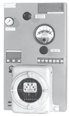
3 Class I ( 2 ft 3 ) and Class II ( 10 ft 3 ) Description Model 2001A is a pressurization or purging system that operates on a supply of compressed instrument air or inert gas. It regulates and monitors pressure within sealed (protected) enclosure(s), in order to prevent combustible dust accumulation or remove and prevent flammable gas or vapor accumulations. In Class II areas, the system maintains a "safe" (1.0") pressure. In Class I areas, the system accomplishes four air exchanges and maintains a "safe" (0.25") pressure. In addition, the system includes an electrical power control unit (EPCU) that monitors system operation and controls enclosure power. All start-up requirements must be satisfied before the EPCU will energize power to the enclosure(s). These processes reduce the hazardous (classified) area rating within the enclosure(s), in accordance with the NEC - NFPA 70, Article 500, NFPA 496 and ISA Basic Operation In accordance with system instructions, start-up requires the air supply to be engaged and EPCU power to be energized. In Class II areas, all dust must be removed from the enclosure(s). The enclosure protection vent (if used) must be tested and enclosure(s) must be sealed. The EPCU power control switch must be activated and the system will self-test. The enclosure pressure control regulator is then used to set a safe reading on the enclosure pressure gauge. In Class II areas, power will energize shortly after safe pressure is stable. In Class I areas, the system must perform an exchange cycle (determined by the safe pressure flow rate five minutes minimum) before power can be energized. Loss of safe pressure causes the EPCU to deenergize power to the protected enclosure(s). All systems include form "C" contacts for audible or visual alarm systems. Model 2001A STD Style (Standard) Standard Model Applications Model Number: 2001A-CI Designation: Purging System Volume: 2 ft 3 max. UL & FM Certified: Cl. I, Div. 1, Group C&D* Rating Reduction: Div. 1 to Nonhazardous Model Number: 2001A-CII Designation: Pressurization System Volume: 10 ft 3 max. UL & FM Certified: Cl. II, Div. 1, Group E-G Rating Reduction: Div. 1 to Nonhazardous *Only FM Certified Group B System Available 3

4 Reference Inlet Gauge EPCU Reference Tubing System Supply Inlet Regulator Supply Outlet Mounting Plate Flame Arrestor Fitting STD Style Venturi Orifice CONNECTION POINTS SHOWN ABOVE IN BOLD TEXT ON SYSTEM DIAGRAM Regulator Body: Regulator Handle: Gauge: Tube Fittings: Tubing: System Nameplates: Fastener Hardware: Mounting Plate: EPCU Body: Warning Nameplate: Material Specifications Lexan is a registered trademark of the General Electric Corporation Zinc w/enamel Finish Polycarbonate Alum. w/enamel Finish 316 SS Forged Body 316 SS 1/4".035 Welded Silkscreened Lexan & SS SS Screws & Bolts Ga #3 Brush SS Bead Blast Cast Alum. Silkscreened SS System Specifications System Dimensions: See page 6 Shipping Weight: 38 lb Temp. Range: -20 F to +120 F Supply Range: * psi max. Supply Requirements: Clean air or inert gas Safe Press. Setpoint (CI/CII): 0.25"/1.0" Safe Press. Flow Rate: ** SCFH Class I Exchange Time: *** As required System Supply Port: 1/4" Tube Fitting Supply Fitting: 1/4" Tube Fitting Reference Fitting: 1/4" Tube Fitting EPCU Conduit Port Size: 1/2" FPT EPCU Power Requirements: 120 VAC 60 Hz 1Ø (European 240 voltage only) 240 VAC 50 Hz 1Ø (All voltage ratings are factory set) EPCU Power Consumption: 500 ma Power Contacts: VAC VDC **** VDC Alarm N.O. Contact: VAC VDC Alarm N.C. Contact: VAC 10 2 VDC * With EPV-1 Vent psi max. to 5 psi min. Systems installed without Vent must be equipped with tamper proof regulator set to 5 psi max. ** integrity determines actual flow rate *** Time required to exchange 4 volumes within the enclosure(s), based on actual measured safe pressure flow rate or 5 minutes, whichever is greater Simplified EPCU Logic Diagram OPERATION Signal (1) from SPS is sent to µp, GAL and SPCR coil. During start-up, GAL verifies all µp functions. GAL & µp must receive uninterrupted signal from SPS to prevent logic resetting. After GAL verifies all start-up procedures, it sends "power enabled" signal (2) to PER coil. Then, µp sends "power request" signal (3) through the SPCR and PER contacts to EPR coils. SPS (1) GAL CLK FAIL PRC µp (2) PER SPCR (3) Electrical Wiring Diagram Field Wired Power Module Terminals EPCU Power Supply Terminals 120 VAC 240 VAC (Optional Voltage) EPR EPR SPS - Safe GAL - Gate Array Logic µp - Microprocessor PER - Power Enabled SPCR - Safe pressure confirmation relay EPR - Power Gnd Gnd Hot Hot 20 A FUSES Neu Neu Isolated Power s Isolated Alarm In Out In Out Power Supply NO Com NC Terminals Remote Alarm Terminals EPCU Description The Pepperl+Fuchs Series EPCU is a factory programmed, field adjustable, microprocessor controlled unit featuring full status indication, redundant gate array logic and electromechanical relays. The EPCU is constructed from four major items: (1) a power module, (2) a pressure switch module, (3) a logic module and (4) a power mode selector switch. The sections are linked with polarized cable, and the boards are stacked in the EPCU enclosure on standoffs. Basic EPCU Operation When power is "off", the EPCU is at rest, alarm and power relays are deenergized, and the LED display is off. When power is switched "on", the EPCU performs a self-test of LED display and logic functions. The unit will then start-up. Class II units must detect a 0.50" pressure to energize the alarm relay. The enclosure power relays energize after a brief delay. Class I units must detect a 0.25" pressure to energize the alarm relay and begin an exchange cycle. When the cycle stops, the power relays will energize. Loss of safe pressure on either unit causes alarm and power relays to deenergize (see power control options for more information regarding EPCU operation). 4

5 Barrier Fault & Active Status Indicators Barrier C Barrier B Barrier A Barrier Wiring Terminal Calibration Access EPCU Logic Module Primary Microprocessor LED Status Display Controller (GAL) Factory Programming Power Module Cable EDT, SLT & RET Timers EPCU Features LED DISPLAY INDICATORS Power Off: Red Power s Deenergized Power On: Green Power s Energized Safe : Blue > 0.15" or 0.50" w.c. Timer Running: Yellow Exchange Timer Active - Class I Only Alarm Active: Red < 0.15" or 0.50" w.c. Bypass Engaged: Green Control Bypass Active - CB Modes Class I LED Displays EPCU Module Primary Safe Space for Optional Safe Alarm Only Class II LED Displays Alarm & Bypass Isolated Coil Voltage Transformer Voltage Input Selector (factory set for 120 or 240 VAC power) Input Fuse RESV RESV Factory Wiring Terminal 120/240 VAC EPCU Power Module Power Control Cable 20 A Power Fuse Power Module Wiring Terminal Assembled Electrical Power Control Unit Voltage Regulators Cable Logic Module Cable Safe 20 A Alarm 20 A Power s Alarm Only Alarm & Bypass FIELD ADJUSTABLE TIMER FUNCTIONS RET (Rapid Exchange Timer) provides a time delay after safe pressure is detected, to allow four volume exchanges prior to energizing the enclosure power relays. In Class I areas only, if safe pressure is lost during time delay cycle, EPCU will reset. NOTE: EDT & SLT timers not functional on Series 2001 Systems Power Control Options NORMAL RUNNING (NR) MODE EPCU features an on-off pushbutton power control switch to activate control functions. must be depressed to initiate start-up. After completion of start-up, safe pressure must be lost or switch must be depressed to deenergize enclosure power relays. CONDITIONAL BYPASS (CB) MODE EPCU features an off-on-bypass power control switch to activate control functions. must be set to "on" position to initiate start-up. After enclosure power is energized, safe pressure must be lost or switch must be set to "off" position to deenergize enclosure power. After enclosure power is energized, switch may be set to "bypass" position to temporarily latch enclosure power relays. A flashing LED then indicates bypass engaged, and the enclosure can then be accessed without deenergizing power (performed under specific conditions). Following access, safe pressure must be reestablished to resume normal operation. At that time, the switch may be reset to the "on" position without disruption of enclosure power. Alarm relay normally deenergizes only upon loss of safe pressure, but can be programmed to deenergize when bypass is engaged, if specified at time of order. 5
6 System Accessories Diagram Model Number Designations 2001A - STD - CI - NR - LH - ## 1/4" Supply Tubing 1/4" Tubing Reference Supply Fitting EBC-4 Reference Fitting EFC-4 Protection Vent EPV-1-SA... (EPV vent not required when using the TR-10G tamper proof regulator as redundancy) Pressurized Protected Mounting Kit SMK-2 or SMK-3 Warning Nameplate EWN- (Included with Panel) Series Model Number System Style STD - Standard Area Classification CI - Class I, Group C & D Area CII - Class II, Group E, F & G Area IB - Class I, Group B Area Power Control Mode NR - Normal Running CB - Conditional Bypass Mounting Configuration LH - left hand left side of enclosure RH - right hand right side of enclosure TM - top mount top of enclosure BM - bottom mount bottom of enclosure WM - wall mount wall surface FM* - frame mount external frame or rack PM* - panel mount enclosure surface cutout * FM & PM configurations feature flush mount EPCU. Flush mount EPCU is not suitable for Group B Area. ## - See Accessories Page 132 for additional factory installed accessories OPTIONAL INTRINSIC SAFETY BARRIERS DESCRIPTION & OPERATION The EPCU Logic Module can accommodate up to three intrinsic safety barriers to interact with remote devices and affect operation of the EPCU. The barriers are installed and programmed by the factory at time of order, and they are designed to function either in conjunction with a customer furnished switch and a Pepperl+Fuchs furnished resistor network cable, or a Pepperl+Fuchs furnished proximity detector. Each barrier develops a low power signal to create a two-wire closed-loop circuit. Operational status of each barrier is indicated by a green LED to show active (closed switch) status, and by a red LED to show faulted (line breakage) cable status. All barriers can be reprogrammed to duplicate other barrier functions as required, upon specific request. BARRIER PROGRAMMING OPTIONS Barrier A Function - when switch opens Disables start-up cycle Deenergizes enclosure power and alarm relay Functions parallel to safe pressure switch Barrier B Function - when switch opens Not programmed - custom applications only Barrier C Function - when switch closes Energizes RESV relay - custom applications only Model 2001A System Accessories (See accessories page for complete details) CONNECTION FITTINGS EFC-4 1/4" Flush Connector EBC-4 1/4" Bulkhead Connector EPC-10 1/2" Pipe Connector ADDITIONAL ITEMS LLF 1/4" Filter SMK-2, -3 or -10 System Mounting Kit RAH Remote Alarm Horn RAB-1 Div. 1 Remote Alarm Beacon LCK L Fitting Conduit Kit TCK T Fitting Conduit Kit SRM-4000 Resistor Module NJ... P+F Namur Sensor INSTALLATION & OPERATION MANUAL Inst. & Operation Manual OPTIONAL ENCLOSURE PROTECTION VENTS EPV-1-SA-00 Straight w/spark Arrestor EPV-1-SA-90 Rt Angle w/spark Arrestor OPTIONAL HEX KEY REGULATOR HANDLE TR-10G Tamper Proof Regulator WARNING NAMEPLATES EWN-1 Class I Warning EWN-2 Class II Warning ETW Temperature Warning FACTORY INSTALLED ACCESSORIES IS1 Channel A Barrier IS2 Channel B Barrier IS3 Channel C Barrier RP1 Safe L Power Key Lock Assembly ONE (1) ENCLOSURE WARNING NAMEPLATE & ONE (1) INSTALLATION & OPERATION MANUAL ARE PROVIDED WITH EACH SYSTEM Overall System Dimensions ` STD Height Width Depth LH - left hand RH - right hand TM - top mount BM - bottom mount WM - wall mount FM or PM - flat panel Dimensions in inches. Mounting dimensions available upon request. FM & PM panel cutout dimensions: 21h x 12w Height & width dimensions reflect mounting plate measurements. Depth dimension reflects overall measurement of system, including components. 6
 enclosure(s), in order to prevent combustible dust accumulation.")
7 Class II ( 50 ft 3 ) Description Model 2001B is a pressurization system that operates on a supply of compressed instrument air or inert gas. It regulates and monitors pressure within sealed (protected) enclosure(s), in order to prevent combustible dust accumulation. Intended exclusively for Class II areas, the system is designed to maintain a "safe" (1.0") pressure. In addition, the system includes an electrical power control unit (EPCU) that monitors system operation and controls enclosure power. All start-up requirements must be satisfied before the EPCU will energize power to the enclosure(s). This process reduces the hazardous (classified) area rating within the enclosure(s), in accordance with the NEC - NFPA 70, Article 500, NFPA 496 and ISA Model 2001B Basic Operation In accordance with system instructions, start-up requires the air supply to be engaged and EPCU power to be energized. The operator is then required to remove all dust from the protected enclosure(s). The enclosure protection vent (if used) must be tested and enclosure(s) must be sealed. The EPCU power control switch must be activated and the system will self-test. The enclosure pressure control regulator is used to set a safe reading on the enclosure pressure gauge. The enclosure power will energize after a brief pause, when safe pressure is stable. Loss of safe pressure causes the EPCU to deenergize power to the protected enclosure(s). The system includes form "C" contacts for audible or visual alarm systems. STD Style (Standard) Standard Model Applications Model Number: Designation: Volume: UL & FM Certified: Rating Reduction: 2001B-CII Pressurization System 50 ft 3 max. Cl. II, Div. 1, Group E-G Div. 1 to Nonhazardous 7

8 Reference Inlet Gauge EPCU Reference Tubing Regulator Body: Regulator Handle: Gauge: Tube Fittings: Tubing: System Nameplates: Fastener Hardware: Mounting Plate: EPCU Body: Warning Nameplate: STD Style Material Specifications System Supply Inlet Lexan is a registered trademark of the General Electric Corporation Regulator Supply Outlet Mounting Plate Flame Arrestor Fitting Venturi Orifice CONNECTION POINTS SHOWN ABOVE IN BOLD TEXT ON SYSTEM DIAGRAM Electrical Wiring Diagram Zinc w/enamel Finish Polycarbonate Alum. w/enamel Finish 316 SS Forged Body 316 SS 1/4".035 Welded Silkscreened Lexan & SS SS Screws & Bolts Ga #3 Brush SS Bead Blast Cast Alum. Silkscreened SS Simplified EPCU Logic Diagram OPERATION Signal (1) from SPS is sent to µp, GAL and SPCR coil. During start-up, GAL verifies all µp functions. GAL & µp must receive uninterrupted signal from SPS to prevent logic resetting. After GAL verifies all start-up procedures, it sends "power enabled" signal (2) to PER coil. Then, µp sends "power request" signal (3) through the SPCR and PER contacts to EPR coils. Field Wired Power Module Terminals SPS (1) GAL CLK FAIL PRC µp (2) PER SPCR (3) EPR EPR SPS - Safe GAL - Gate Array Logic µp - Microprocessor PER - Power Enabled SPCR - Safe pressure confirmation relay EPR - Power 20 A FUSES Isolated Power s Isolated Alarm System Specifications System Dimensions: See page 10 Shipping Weight: 38 lb Temp. Range: -20 F to +120 F Supply Range: * psi max. Supply Requirements: Clean air or inert gas Safe Press. Setpoint: Safe Press. Safe Press. Flow Rate: ** SCFH System Supply Port: 3/8" Tube Fitting Supply Fitting: 3/8" Tube Fitting Reference Fitting: 1/4" Tube Fitting EPCU Conduit Port Size: 1/2" FPT EPCU Power Requirements: 120 VAC 60 Hz 1Ø (European 220 voltage only) 240 VAC 50 Hz 1Ø (All voltage ratings are factory set) EPCU Power Consumption: 500 ma Power Contacts: VAC VDC *** VDC Alarm N.O. Contact: VAC VDC Alarm N.C. Contact: VAC VDC * With EPV-3 Vent psi max. to 5 psi min. Systems installed without Vent must be equipped with tamper proof regulator set to 5 psi max. ** integrity determines actual flow rate EPCU Description The Pepperl+Fuchs Series EPCU is a factory programmed, field adjustable, microprocessor controlled unit featuring full status indication, redundant gate array logic and electromechanical relays. The EPCU is constructed from four major items: (1) a power module, (2) a pressure switch module, (3) a logic module and (4) a power mode selector switch. The sections are linked with polarized cable, and the boards are stacked in the EPCU enclosure on standoffs. Basic EPCU Operation When power is "off", the EPCU is at rest, alarm and power relays are deenergized, and the LED display is off. When power is switched "on", the EPCU performs a self-test of LED display and logic functions. The unit will then start-up. Class II units must detect a 0.50" pressure to energize the alarm relay. The enclosure power relays energize after a brief delay. Loss of safe pressure on the unit causes alarm and power relays to deenergize (see power control options for more information regarding EPCU operation). EPCU Power Supply Terminals 120 VAC 240 VAC (Optional Voltage) Gnd Gnd Hot Hot Neu Neu In Out In Out Power Supply NO Com NC Terminals Remote Alarm Terminals 8

9 Barrier Fault & Active Status Indicators Barrier C Barrier B Barrier A Barrier Wiring Terminal Calibration Access EPCU Logic Module Primary Microprocessor LED Status Display Controller (GAL) Factory Programming Power Module Cable EDT, SLT & RET Timers EPCU Features LED DISPLAY INDICATORS Power Off: Red Power s Deenergized Power On: Green Power s Energized Safe : Blue > 0.50" w.c. Alarm Active: Red < 0.50" w.c. Bypass Engaged: Green Control Bypass Active - CB Modes Class II LED Displays EPCU Module Primary Safe Space for Optional Safe Alarm Only Alarm & Bypass FIELD ADJUSTABLE TIMER FUNCTIONS RET, EDT & SLT timers not functional on Model 2001B Systems Power Control Options Isolated Coil Voltage Transformer Voltage Input Selector (factory set for 120 or 240 VAC power) Input Fuse RESV RESV Factory Wiring Terminal 120/240 VAC EPCU Power Module Power Control Cable 20 A Power Fuse Power Module Wiring Terminal Voltage Regulators Cable Logic Module Cable Safe 20 A Alarm 20 A Power s NORMAL RUNNING (NR) MODE EPCU features an on-off pushbutton power control switch to activate control functions. must be depressed to initiate start-up. After completion of start-up, safe pressure must be lost or switch must be depressed to deenergize enclosure power relays. CONDITIONAL BYPASS (CB) MODE EPCU features an off-on-bypass power control switch to activate control functions. must be set to "on" position to initiate start-up. After enclosure power is energized, safe pressure must be lost or switch must be set to "off" position to deenergize enclosure power. After enclosure power is energized, switch may be set to "bypass" position to temporarily latch enclosure power relays. A flashing LED then indicates bypass engaged, and the enclosure can be accessed without deenergizing power (performed under specific conditions). Following access, safe pressure must be reestablished to resume normal operation. At that time, the switch may be reset to the "on" position without disruption of enclosure power. Alarm relay normally deenergizes only upon loss of safe pressure, but can be programmed to deenergize when bypass is engaged, if specified at time of order. Assembled Electrical Power Control Unit 9
10 System Accessories Diagram Model Number Designations 2001B - STD - CII - NR - LH - ## 3/8" Supply Tubing 1/4" Tubing Reference Supply Fitting EBC-6 Reference Fitting EFC-4 Protection Vent EPV-3-SA... Pressurized Protected Mounting Kit SMK-2 or SMK-3 Warning Nameplate EWN-2 (Included with Panel) Series Model Number System Style STD - Standard Area Classification CII - Class II, Group E, F & G Area Power Control Mode NR - Normal Running CB - Conditional Bypass Mounting Configuration LH - left hand left side of enclosure RH - right hand right side of enclosure TM - top mount top of enclosure BM - bottom mount bottom of enclosure WM - wall mount wall surface FM* - frame mount external frame or rack PM* - panel mount enclosure surface cutout * FM & PM configurations feature flush mount EPCU. ## - See Accessories Page 132 for additional factory installed accessories OPTIONAL INTRINSIC SAFETY BARRIERS DESCRIPTION & OPERATION The EPCU Logic Module can accommodate up to three intrinsic safety barriers to interact with remote devices and affect operation of the EPCU. The barriers are installed and programmed by the factory at time of order, and they are designed to function either in conjunction with a customer furnished switch and a Pepperl+Fuchs furnished resistor network cable, or a Pepperl+Fuchs furnished proximity detector. Each barrier develops a low power signal to create a two-wire closed-loop circuit. Operational status of each barrier is indicated by a green LED to show active (closed switch) status, and by a red LED to show faulted (line breakage) cable status. All barriers can be reprogrammed to duplicate other barrier functions as required, upon specific request. BARRIER PROGRAMMING OPTIONS Barrier A Function - when switch opens Disables start-up cycle Deenergizes enclosure power and alarm relay Functions parallel to safe pressure switch Barrier B Function - when switch opens Not programmed - custom applications only Barrier C Function - when switch closes Energizes RESV relay - custom applications only Model 2001B System Accessories (See accessories page for complete details) CONNECTION FITTINGS EFC-4 1/4" Flush Connector EFC-6 3/8" Flush Connector EBC-6 3/8" Bulkhead Connector EPC-13 1" Pipe Connector ADDITIONAL ITEMS SMK-2, -3 or -10 System Mounting Kit RAH Remote Alarm Horn RAB-1 Div. 1 Remote Alarm Beacon LCK L Fitting Conduit Kit TCK T Fitting Conduit Kit SRM-4000 Resistor Module NJ... P+F Namur Sensor INSTALLATION & OPERATION MANUAL Inst. & Operation Manual OPTIONAL ENCLOSURE PROTECTION VENTS EPV-3-SA-00 Straight w/spark Arrestor EPV-3-SA-90 Rt Angle w/spark Arrestor WARNING NAMEPLATES EWN-2 Class II Warning ETW Temperature Warning FACTORY INSTALLED ACCESSORIES IS1 Channel A Barrier IS2 Channel B Barrier IS3 Channel C Barrier RP1 Safe L Power Key Lock Assembly ONE (1) ENCLOSURE WARNING NAMEPLATE & ONE (1) INSTALLATION & OPERATION MANUAL ARE PROVIDED WITH EACH SYSTEM Overall System Dimensions ` STD Height Width Depth LH - left hand RH - right hand TM - top mount BM - bottom mount WM - wall mount FM or PM - flat panel Dimensions in inches. Mounting dimensions available upon request. FM & PM panel cutout dimensions: 21h x 12w Height & width dimensions reflect mounting plate measurements. Depth dimension reflects overall measurement of system, including components
 enclosure(s), in order to prevent combustible dust accumulation.")
11 Class II ( 250 ft 3 ) Description Model 2001C is a pressurization system that operates on a supply of compressed instrument air or inert gas. It regulates and monitors pressure within sealed (protected) enclosure(s), in order to prevent combustible dust accumulation. Intended exclusively for Class II areas, the system is designed to maintain a "safe" (1.0") pressure. In addition, the system includes an electrical power control unit (EPCU) that monitors system operation and controls enclosure power. All start-up requirements must be satisfied before the EPCU will energize power to the enclosure(s). This process reduces the hazardous (classified) area rating within the enclosure(s), in accordance with the NEC - NFPA 70, Article 500, NFPA 496 and ISA Model 2001C Basic Operation In accordance with system instructions, start-up requires the air supply to be engaged and EPCU power to be energized. The operator is then required to remove all dust from the protected enclosure(s). The enclosure protection vent (if used) must be tested and enclosure(s) must be sealed. The EPCU power control switch must be activated and the system will self-test. The enclosure pressure control regulator is used to set a safe reading on the enclosure pressure gauge. The enclosure power will energize after a brief pause, when safe pressure is stable. Loss of safe pressure causes the EPCU to deenergize power to the protected enclosure(s). The system includes form "C" contacts for audible or visual alarm systems. STD Style (Standard) Standard Model Applications Model Number: Designation: Volume: UL & FM Certified: Rating Reduction: 2001C-CII Pressurization System 250 ft 3 max. Cl. II, Div. 1, Group E-G Div. 1 to Nonhazardous 11

12 Reference Inlet Gauge EPCU Reference Tubing Regulator Body: Regulator Handle: Gauge: Tube Fittings: Tubing: System Nameplates: Fastener Hardware: Mounting Plate: EPCU Body: Warning Nameplate: STD Style Material Specifications Lexan is a registered trademark of the General Electric Corporation System Supply Inlet Regulator Supply Outlet Mounting Plate Flame Arrestor Fitting Venturi Orifice CONNECTION POINTS SHOWN ABOVE IN BOLD TEXT ON SYSTEM DIAGRAM Electrical Wiring Diagram Zinc w/enamel Finish Polycarbonate Alum. w/enamel Finish 316 SS Forged Body 316 SS 1/4".035 Welded Silkscreened Lexan & SS SS Screws & Bolts Ga #3 Brush SS Bead Blast Cast Alum. Silkscreened SS Simplified EPCU Logic Diagram OPERATION Signal (1) from SPS is sent to µp, GAL and SPCR coil. During start-up, GAL verifies all µp functions. GAL & µp must receive uninterrupted signal from SPS to prevent logic resetting. After GAL verifies all start-up procedures, it sends "power enabled" signal (2) to PER coil. Then, µp sends "power request" signal (3) through the SPCR and PER contacts to EPR coils. Field Wired Power Module Terminals SPS (1) GAL CLK FAIL PRC µp (2) PER SPCR (3) EPR EPR SPS - Safe GAL - Gate Array Logic µp - Microprocessor PER - Power Enabled SPCR - Safe pressure confirmation relay EPR - Power 20 A FUSES Isolated Power s Isolated Alarm System Specifications System Dimensions: See page 14 Shipping Weight: 38 lb Temp. Range: -20 F to +120 F Supply Range: * psi max. Supply Requirements: Clean air or inert gas Safe Press. Setpoint: Safe Press. Safe Press. Flow Rate: ** SCFH System Supply Port: 1/2" Tube Fitting Supply Fitting: 1/2" Tube Fitting Reference Fitting: 1/4" Tube Fitting EPCU Conduit Port Size: 1/2" FPT EPCU Power Requirements: 120 VAC 60 Hz 1Ø (European 220 voltage only) 240 VAC 50 Hz 1Ø (All voltage ratings are factory set) EPCU Power Consumption: 500 ma Power Contacts: VAC VDC *** VDC Alarm N.O. Contact: VAC VDC Alarm N.C. Contact: VAC VDC * With EPV-4 Vent psi max. to 5 psi min. Systems installed without Vent must be equipped with tamper proof regulator set to 5 psi max. ** integrity determines actual flow rate EPCU Description The Pepperl+Fuchs Series EPCU is a factory programmed, field adjustable, microprocessor controlled unit featuring full status indication, redundant gate array logic and electromechanical relays. The EPCU is constructed from four major items: (1) a power module, (2) a pressure switch module, (3) a logic module and (4) a power mode selector switch. The sections are linked with polarized cable, and the boards are stacked in the EPCU enclosure on standoffs. Basic EPCU Operation When power is "off", the EPCU is at rest, alarm and power relays are deenergized, and the LED display is off. When power is switched "on", the EPCU performs a self-test of LED display and logic functions. The unit will then start-up. Class II units must detect a 0.50" pressure to energize the alarm relay. The enclosure power relays energize after a brief delay. Loss of safe pressure on the unit causes alarm and power relays to deenergize (see power control options for more information regarding EPCU operation). EPCU Power Supply Terminals 120 VAC 240 VAC (Optional Voltage) Gnd Gnd Hot Hot Neu Neu In Out In Out Power Supply NO Com NC Terminals Remote Alarm Terminals 12
13 Barrier Fault & Active Status Indicators Barrier C Barrier B Barrier A Barrier Wiring Terminal Calibration Access EPCU Logic Module Primary Microprocessor LED Status Display Controller (GAL) Factory Programming Power Module Cable EDT, SLT & RET Timers EPCU Features LED DISPLAY INDICATORS Power Off: Red Power s Deenergized Power On: Green Power s Energized Safe : Blue > 0.50" w.c. Alarm Active: Red < 0.50" w.c. Bypass Engaged: Green Control Bypass Active - CB Modes Class II LED Displays EPCU Module Primary Safe Isolated Coil Voltage Transformer Voltage Input Selector (factory set for 120 or 240 VAC power) Input Fuse RESV RESV Factory Wiring Terminal 120/240 VAC EPCU Power Module Power Control Cable 20 A Power Fuse Power Module Wiring Terminal Space for Optional Safe Voltage Regulators Cable Logic Module Cable Safe 20 A Alarm 20 A Power s Alarm Only Alarm & Bypass FIELD ADJUSTABLE TIMER FUNCTIONS RET, EDT & SLT timers not functional on Model 2001B Systems Power Control Options NORMAL RUNNING (NR) MODE EPCU features an on-off pushbutton power control switch to activate control functions. must be depressed to initiate start-up. After completion of start-up, safe pressure must be lost or switch must be depressed to deenergize enclosure power relays. CONDITIONAL BYPASS (CB) MODE EPCU features an off-on-bypass power control switch to activate control functions. must be set to "on" position to initiate start-up. After enclosure power is energized, safe pressure must be lost or switch must be set to "off" position to deenergize enclosure power. After enclosure power is energized, switch may be set to "bypass" position to temporarily latch enclosure power relays. A flashing LED then indicates bypass engaged, and the enclosure can be accessed without deenergizing power (performed under specific conditions). Following access, safe pressure must be reestablished to resume normal operation. At that time, the switch may be reset to the "on" position without disruption of enclosure power. Alarm relay normally deenergizes only upon loss of safe pressure, but can be programmed to deenergize when bypass is engaged, if specified at time of order. Assembled Electrical Power Control Unit 13
14 System Accessories Diagram Model Number Designations 2001C - STD - CII - NR - LH - ## 1/2" Supply Tubing 1/4" Tubing Reference Supply Fitting EBC-8 Reference Fitting EFC-4 Protection Vent EPV-4-SA... Pressurized Protected Mounting Kit SMK-3 Warning Nameplate EWN-2 (Included with Panel) Series Model Number System Style STD - Standard Area Classification CII - Class II, Group E, F & G Area Power Control Mode NR - Normal Running CB - Conditional Bypass Mounting Configuration LH - left hand left side of enclosure RH - right hand right side of enclosure TM - top mount top of enclosure BM - bottom mount bottom of enclosure WM - wall mount wall surface FM* - frame mount external frame or rack PM* - panel mount enclosure surface cutout * FM & PM configurations feature flush mount EPCU. ## - See Accessories Page 132 for additional factory installed accessories OPTIONAL INTRINSIC SAFETY BARRIERS DESCRIPTION & OPERATION The EPCU Logic Module can accommodate up to three intrinsic safety barriers to interact with remote devices and affect operation of the EPCU. The barriers are installed and programmed by the factory at time of order, and they are designed to function either in conjunction with a customer furnished switch and a Pepperl+Fuchs furnished resistor network cable, or a Pepperl+Fuchs furnished proximity detector. Each barrier develops a low power signal to create a two-wire closed-loop circuit. Operational status of each barrier is indicated by a green LED to show active (closed switch) status, and by a red LED to show faulted (line breakage) cable status. All barriers can be reprogrammed to duplicate other barrier functions as required, upon specific request. BARRIER PROGRAMMING OPTIONS Barrier A Function - when switch opens Disables start-up cycle Deenergizes enclosure power and alarm relay Functions parallel to safe pressure switch Barrier B Function - when switch opens Not programmed - custom applications only Barrier C Function - when switch closes Energizes RESV relay - custom applications only Model 2001C System Accessories (See accessories page for complete details) CONNECTION FITTINGS EFC-4 1/4" Flush Connector EFC-8 1/2" Flush Connector EBC-8 1/2" Bulkhead Connector EPC /2" Pipe Connector ADDITIONAL ITEMS SMK-2, -3 or -10 System Mounting Kit RAH Remote Alarm Horn RAB-1 Div. 1 Remote Alarm Beacon LCK L Fitting Conduit Kit TCK T Fitting Conduit Kit SRM-4000 Resistor Module NJ... P+F Namur Senor INSTALLATION & OPERATION MANUAL Inst. & Operation Manual OPTIONAL ENCLOSURE PROTECTION VENTS EPV-4-SA-00 Straight w/spark Arrestor EPV-4-SA-90 Rt Angle w/spark Arrestor WARNING NAMEPLATES EWN-2 Class II Warning ETW Temperature Warning FACTORY INSTALLED ACCESSORIES IS1 Channel A Barrier IS2 Channel B Barrier IS3 Channel C Barrier RP1 Safe L Power Key Lock Assembly ONE (1) ENCLOSURE WARNING NAMEPLATE & ONE (1) INSTALLATION & OPERATION MANUAL ARE PROVIDED WITH EACH SYSTEM Overall System Dimensions ` STD Height Width Depth LH - left hand RH - right hand TM - top mount BM - bottom mount WM - wall mount FM or PM - flat panel Dimensions in inches. Mounting dimensions available upon request. FM & PM panel cutout dimensions: 21h x 12w Height & width dimensions reflect mounting plate measurements. Depth dimension reflects overall measurement of system, including components. 14
 enclosure(s), in order to remove and prevent flammable gas or vapor accumulations.")
 that monitors system operation and controls enclosure power.")
15 Class I ( 15 ft 3 ) Description Model 2002 is a Rapid Exchange purging system that operates on a supply of compressed instrument air or inert gas. It regulates and monitors pressure within sealed (protected) enclosure(s), in order to remove and prevent flammable gas or vapor accumulations. The system accomplishes four air exchanges and maintains a "safe" (0.25") pressure. A Pepperl+Fuchs Model EPV-2 enclosure protection vent is required for proper operation. In addition, the system includes an electrical power control unit (EPCU) that monitors system operation and controls enclosure power. All start-up requirements must be satisfied before the EPCU will energize power to the enclosure(s). This process reduces the hazardous (classified) area rating within the enclosure(s), in accordance with the NEC - NFPA 70, Article 500, NFPA 496 and ISA Basic Operation Model 2002 In accordance with system instructions, start-up requires the air supply to be engaged and EPCU power to be energized. The enclosure protection vent must be tested and the enclosure(s) must be sealed. The EPCU power control switch must be activated and the system will self-test. The enclosure pressure control valve is used to manually set a safe reading on the enclosure pressure indicator. When safe pressure is stable, the Rapid Exchange control valve is fully engaged by manual or automatic means (dependent on System Style, see below). Upon completion of the Rapid Exchange cycle, (five minutes minimum) the Rapid Exchange control valve disengages manually or automatically. returns to the safe setting and enclosure power is energized by the EPCU. Loss of safe pressure causes the EPCU to deenergize power to the protected enclosure(s). All systems include form "C" contacts for audible or visual alarm systems. STD Style (Standard) FA/SA Style (Fully Automatic/Semiautomatic) Style Variances STD (Standard) Style systems require manual operation of the Rapid Exchange control valve. SA (Semiautomatic) Style systems require manual engagement of the Rapid Exchange control valve to initiate the exchange cycle, but automatically disengages the valve upon completion of the cycle. Loss of safe pressure requires an operator to manually restart both systems above FA (Fully Automatic) Style systems engage and disengage the Rapid Exchange control valve automatically, after an operator manually sets a safe pressure. In addition, FA Style systems restart automatically after a power or air pressure failure. Rapid Exchange is a Registered Trademark of Pepperl+Fuchs, Inc. SA (Semiautomatic) Style UL & FM Certified: Cl. I, Div. 1, Group C&D Rating Reduction: Standard Model Applications Model Number: 2002 Designation: Purging System Volume: 15 ft 3 max. STD (Standard) Style UL & FM Certified: Cl. I, Div. 1, Group C&D* Rating Reduction: Div. 1 to Nonhazardous Div. 1 to Nonhazardous FA (Fully Automatic) Style UL & FM Certified: Cl. I, Div. 1, Group C&D Rating Reduction: Div. 1 to Nonhazardous *Only FM Certified Group B System Available in STD Style 15
16 STD Style Gauge Reference Inlet Control Valve RESV Conduit EPCU Reference Tubing Flame Arrestor Fitting Filter Regulator Body: Regulator Handle & Bowl: Gauge: Rapid Exchange Gauge: Rapid Exchange Solenoid: Tube Fittings & Valves: Tubing: System Nameplates: Fastener Hardware: Mounting Plate: EPCU Body: Conduit & Fittings (SA & FA): Warning Nameplate: Material Specifications Lexan is a registered trademark of the General Electric Corporation Rapid Exchange Solenoid Valve Filter Regulator System Supply Inlet Supply Outlet Mounting Plate Venturi Orifice (not visible) SA & FA Style (with Rapid Exchange Solenoid Valve) CONNECTION POINTS SHOWN ABOVE IN BOLD TEXT ON SYSTEM DIAGRAM Electrical Wiring Diagram Zinc w/enamel Finish Polycarbonate Alum. w/enamel Finish Poly Case & Brass Tube Brass w/enamel Finish 316 SS Forged Body 316 SS 1/4".035 Welded Silkscreened Lexan & SS SS Screws & Bolts Ga #3 Brush SS Bead Blast Cast Alum. Galvanized Steel Silkscreened SS Simplified EPCU Logic Diagram OPERATION Signal (1) from SPS is sent to µp, GAL and SPCR coil. During start-up, GAL verifies all µp functions. GAL & µp must receive uninterrupted signal from SPS to prevent logic resetting. After GAL verifies all start-up procedures, it sends "power enabled" signal (2) to PER coil. Then, µp sends "power request" signal (3) through the SPCR and PER contacts to EPR coils. Field Wired Power Module Terminals SPS (1) GAL CLK FAIL PRC µp (2) PER SPCR (3) EPR EPR SPS - Safe GAL - Gate Array Logic µp - Microprocessor PER - Power Enabled SPCR - Safe pressure confirmation relay EPR - Power 20 A FUSES Isolated Power s Isolated Alarm System Specifications System Dimensions: See page 18 Shipping Weight (lb): STD - 45 / SA & FA - 47 Temp. Range: -20 F to +120 F Supply Range: psi max. Capacity & Filtration: Microns Supply Requirements: Clean air or inert gas Safe Press. Setpoint: Safe Press. Safe Press. Flow Rate: * SCFH Exchange : 3" - 5" Exchange Flow Rate: ** 4 SCFM / 240 SCFH Exchange Time: 1 Minute/ft 3 System Supply Port: 1/4" FPT Supply Fitting: 1/4" Tube Fitting Reference Fitting: 1/4" Tube Fitting EPCU Conduit Port Size: 1/2" FPT EPCU Power Requirements: 120 VAC 60 Hz 1Ø (European 220 voltage only) 240 VAC 50 Hz 1Ø (All voltage ratings are factory set) EPCU Power Consumption: Power Contacts: Alarm N.O. Contact: Alarm N.C. Contact: 500 ma VAC VDC *** VDC VAC VDC VAC VDC * integrity determines actual flow rate ** With regulator set to 60 psi min. during exchange EPCU Description The Pepperl+Fuchs Series EPCU is a factory programmed, field adjustable, microprocessor controlled unit featuring full status indication, redundant gate array logic and electromechanical relays. The EPCU is constructed from four major items: (1) a power module, (2) a pressure switch module, (3) a logic module and (4) a power mode selector switch. The sections are linked with polarized cable, and the boards are stacked in the EPCU enclosure on standoffs. Basic EPCU Operation When power is "off", the EPCU is at rest, alarm and power relays are deenergized, and the LED display is off. When power is switched "on", the EPCU performs a self-test of LED display and logic functions. The unit will then start-up. Class I units must detect a 0.25" pressure to energize the alarm relay and begin an exchange cycle. When the cycle stops, the power relays will energize. Loss of safe pressure on either unit causes alarm and power relays to deenergize (see power control options for more information regarding EPCU operation). EPCU Power Supply Terminals 120 VAC 240 VAC (Optional Voltage) Gnd Gnd Hot Hot Neu Neu In Out In Out Power Supply NO Com NC Terminals Remote Alarm Terminals 16
17 Barrier Fault & Active Status Indicators Barrier C Barrier B Barrier A Barrier Wiring Terminal Calibration Access EPCU Logic Module Primary Microprocessor LED Status Display Controller (GAL) Factory Programming Power Module Cable EDT, SLT & RET Timers EPCU Features LED DISPLAY INDICATORS Power Off: Red Power s Deenergized Power On: Green Power s Energized Safe : Blue > 0.15" w.c. Rapid Exchange: Blue > 2.0" w.c. Timer Running: Yellow Rapid Exchange Timer Active Alarm Active: Red < 0.15" w.c. Bypass Engaged: Green Control Bypass Active - CB EPCU Module Primary Safe Space for Optional Safe Isolated Coil Voltage Transformer Voltage Input Selector (factory set for 120 or 240 VAC power) Input Fuse RESV 120/240 VAC EPCU Power Module Power Control Cable Primary Rapid Exchange Space for Optional Rapid Exchange Voltage Regulators Cable Logic Module Cable Safe Rapid Exchange Alarm Only Alarm & Bypass FIELD ADJUSTABLE TIMER FUNCTIONS EDT (Exchange Delay Timer) (FA Style only) provides a time delay to prevent Rapid Exchange solenoid valve from energizing until safe pressure can be stabilized. SLT (Solenoid Latching Timer) (FA Style only) provides a time delay to keep the Rapid Exchange solenoid valve energized until exchange pressure is detected. If the pressure is not detected, the EPCU will reset. RET (Rapid Exchange Timer) provides a time delay after Rapid Exchange pressure is detected, to allow four volume exchanges prior to energizing the enclosure power relays. If safe pressure or Rapid Exchange pressure is lost or interrupted during time delay cycle, the EPCU will reset. Power Control Options NORMAL RUNNING (NR) MODE EPCU features an on-off pushbutton power control switch to activate control functions. must be depressed to initiate start-up. After completion of start-up, safe pressure must be lost or switch must be depressed to deenergize enclosure power relays. RESV Factory Wiring Terminal 20 A Power Fuse Power Module Wiring Terminal Assembled Electrical Power Control Unit 20 A Alarm 20 A Power s CONDITIONAL BYPASS (CB) MODE EPCU features an off-on-bypass power control switch to activate control functions. must be set to "on" position to initiate start-up. After enclosure power is energized, safe pressure must be lost or switch must be set to "off" position to deenergize enclosure power. After enclosure power is energized, switch may be set to "bypass" position to temporarily latch enclosure power relays. A flashing LED then indicates bypass engaged, and the enclosure can be accessed without deenergizing power (performed under specific conditions). Following access, safe pressure must be reestablished to resume normal operation. At that time, the switch may be reset to the "on" position without disruption of enclosure power. Alarm relay normally deenergizes only upon loss of safe pressure, but can be programmed to deenergize when bypass is engaged, if specified at time of order. 17
18 System Accessories Diagram Model Number Designations Supply Inlet Fitting SC-4 or NC-4 1/4" Supply Tubing 1/4" Tubing Reference Supply Fitting EBC-4 Reference Fitting EFC-4 Protection Vent EPV-2-SA... Pressurized Protected Mounting Kit SMK-3 Warning Nameplate EWN-1 (Included with Panel) OPTIONAL INTRINSIC SAFETY BARRIERS DESCRIPTION & OPERATION The EPCU Logic Module can accommodate up to three intrinsic safety barriers to interact with remote devices and affect operation of the EPCU. The barriers are installed and programmed by the factory at time of order, and they are designed to function either in conjunction with a customer furnished switch and a Pepperl+Fuchs furnished resistor network cable, or a Pepperl+Fuchs furnished proximity detector. Each barrier develops a low power signal to create a two-wire closed-loop circuit. Operational status of each barrier is indicated by a green LED to show active (closed switch) status, and by a red LED to show faulted (line breakage) cable status. All barriers can be reprogrammed to duplicate other barrier functions as required, upon specific request STD - CI - NR - LH - ## Series Model Number System Style STD - Standard SA - Semiautomatic FA - Fully Automatic Area Classification CI - Class I, Group C & D Area IB - Class I, Group B Area (STD Only) Power Control Mode NR - Normal Running CB - Conditional Bypass Mounting Configuration LH - left hand left side of enclosure RH - right hand right side of enclosure TM - top mount top of enclosure BM - bottom mount bottom of enclosure WM - wall mount wall surface FM* - frame mount external frame or rack PM* - panel mount enclosure surface cutout * FM & PM configurations feature flush mount EPCU. Flush mount EPCU is not suitable for Group B Area. ## - See Accessories Page 132 for additional factory installed accessories BARRIER PROGRAMMING OPTIONS Barrier A Function - when switch opens Disables start-up cycle Deenergizes enclosure power and alarm relay Functions parallel to safe pressure switch Barrier B Function - when switch opens Not programmed - custom applications only Barrier C Function - when switch closes Energizes RESV relay - custom applications only Model 2002 System Accessories (See accessories page for complete details) CONNECTION FITTINGS TCK T Fitting Conduit Kit WARNING NAMEPLATES NC-4 1/4" Ninety Connector SRM-4000 Resistor Module EWN-1 Class I Warning SC-4 1/4" Straight Connector NJ... P+F Namur Sensor ETW Temperature Warning EFC-4 1/4" Flush Connector INSTALLATION & OPERATION MANUAL FACTORY INSTALLED ACCESSORIES EBC-4 1/4" Bulkhead Connector Inst. & Operation Manual IS1 Channel A Barrier EPC-12 3/4" Pipe Connector ENCLOSURE PROTECTION VENTS IS2* Channel B Barrier ADDITIONAL ITEMS ONE VENT REQUIRED WITH EACH SYSTEM IS3* Channel C Barrier SMK-2, -3 or -10 System Mounting Kit EPV-2-SA-00 Straight w/spark Arrestor RP1 Safe RAH Remote Alarm Horn EPV-2-SA-90 Rt Angle w/spark Arrestor RP2 Rapid Exchange RAB-1 Div. 1 Remote Alarm Beacon L Power Key Lock Assembly LCK L Fitting Conduit Kit *Requires custom programming information ONE (1) ENCLOSURE WARNING NAMEPLATE & ONE (1) INSTALLATION & OPERATION MANUAL ARE PROVIDED WITH EACH SYSTEM Overall System Dimensions STD / SA & FA LH - left hand RH - right hand TM - top mount BM - bottom mount WM - wall mount FM or PM - flat panel Height Width Depth / / / / / / Dimensions in inches. Mounting dimensions available upon request. FM & PM panel cutout dimensions: 23h x 12w Height & width dimensions reflect mounting plate measurements. Depth dimension reflects overall measurement of system, including components. 18
 enclosure(s), in order to remove and prevent flammable gas or vapor accumulations.")
 that monitors system operation and controls enclosure power.")
19 Class I ( 75 ft 3 ) Description Model 2003 is a Rapid Exchange purging system that operates on a supply of compressed instrument air or inert gas. It regulates and monitors pressure within sealed (protected) enclosure(s), in order to remove and prevent flammable gas or vapor accumulations. The system accomplishes four air exchanges and maintains a "safe" (0.25") pressure. A Pepperl+Fuchs Model EPV-3 Protection Vent is required for proper operation. In addition, the system includes an electrical power control unit (EPCU) that monitors system operation and controls enclosure power. All start-up requirements must be satisfied before the EPCU will energize power to the enclosure(s). This process reduces the hazardous (classified) area rating within the enclosure(s), in accordance with the NEC - NFPA 70, Article 500, NFPA 496 and ISA Basic Operation Model 2003 In accordance with system instructions, start-up requires the air supply to be engaged and EPCU power to be energized. The enclosure protection vent must be tested and the enclosure(s) must be sealed. The EPCU power control switch must be activated and the system will self-test. The enclosure pressure control valve is used to manually set a safe reading on the enclosure pressure indicator. When safe pressure is stable, the Rapid Exchange control valve is fully engaged by manual or automatic means (dependent on System Style, see below). Upon completion of the Rapid Exchange cycle, (five minutes minimum) the Rapid Exchange control valve disengages manually or automatically. returns to the safe setting and enclosure power is energized by the EPCU. Loss of safe pressure causes the EPCU to deenergize power to the protected enclosure(s). All systems include form "C" contacts for audible or visual alarm systems. STD Style (Standard) FA/SA Style (Fully Automatic/Semiautomatic) Style Variances STD (Standard) Style systems require manual operation of the Rapid Exchange control valve. SA (Semiautomatic) Style systems require manual engagement of the Rapid Exchange control valve to initiate the exchange cycle, but automatically disengages the valve upon completion of the cycle. Loss of safe pressure requires an operator to manually restart both systems above. FA (Fully Automatic) Style systems engage and disengage the Rapid Exchange control valve automatically, after an operator manually sets a safe pressure. In addition, FA Style systems restart automatically after a power or air pressure failure. Rapid Exchange is a Registered Trademark of Pepperl+Fuchs. SA (Semiautomatic) Style UL & FM Certified: Cl. I, Div. 1, Group C&D Rating Reduction: Standard Model Applications Model Number: 2003 Designation: Purging System Volume: 75 ft 3 max. STD (Standard) Style UL & FM Certified: Cl. I, Div. 1, Group C&D* Rating Reduction: Div. 1 to Nonhazardous Div. 1 to Nonhazardous FA (Fully Automatic) Style UL & FM Certified: Cl. I, Div. 1, Group C&D Rating Reduction: Div. 1 to Nonhazardous *Only FM Certified Group B System Available in STD Style 19
20 STD Style Gauge Reference Inlet Control Valve RESV Conduit EPCU Reference Tubing Flame Arrestor Fitting Filter Regulator Body: Regulator Handle & Bowl: Gauge: Rapid Exchange Gauge: Rapid Exchange Solenoid: Tube Fittings & Valves: Tubing: System Nameplates: Fastener Hardware: Mounting Plate: EPCU Body: Conduit & Fittings (SA & FA): Warning Nameplate: Material Specifications Rapid Exchange Solenoid Valve Filter Regulator System Supply Inlet Supply Outlet Mounting Plate Venturi Orifice (not visible) SA & FA Style (with Rapid Exchange Solenoid Valve) CONNECTION POINTS SHOWN ABOVE IN BOLD TEXT ON SYSTEM DIAGRAM Zinc w/enamel Finish Polycarbonate Alum. w/enamel Finish Poly Case & Brass Tube Brass w/enamel Finish 316 SS Forged Body 316 SS 1/4" & 3/8".035 Welded Silkscreened Lexan & SS SS Screws & Bolts Ga #3 Brush SS Bead Blast Cast Alum. Galvanized Steel Silkscreened SS System Specifications System Dimensions: See page 22 Shipping Weight: STD - 45 lb / SA & FA - 47 lb Temp. Range: -20 F to +120 F Supply Range: psi max. Capacity & Filtration: Microns Supply Requirements: Clean air or inert gas Safe Press. Setpoint: Safe Press. Safe Press. Flow Rate: * SCFH Exchange : 3" - 5" Exchange Flow Rate: ** 10 SCFM / 600 SCFH Exchange Time: 1 Minute / 2.5 ft 3 System Supply Port: 3/8" FPT Supply Fitting: 3/8" Tube Fitting Reference Fitting: 1/4" Tube Fitting EPCU Conduit Port Size: 1/2" FPT EPCU Power Requirements: 120 VAC 60 Hz 1Ø (European 220 voltage only) 240 VAC 50 Hz 1Ø (All voltage ratings are factory set) EPCU Power Consumption: 500 ma Power Contacts: VAC VDC *** VDC Alarm N.O. Contact: VAC VDC Alarm N.C. Contact: VAC VDC * integrity determines actual flow rate ** With regulator set to 60 psi min. during exchange EPCU Description Lexan is a registered trademark of the General Electric Corporation Simplified EPCU Logic Diagram OPERATION Signal (1) from SPS is sent to µp, GAL and SPCR coil. During start-up, GAL verifies all µp functions. GAL & µp must receive uninterrupted signal from SPS to prevent logic resetting. After GAL verifies all start-up procedures, it sends "power enabled" signal (2) to PER coil. Then, µp sends "power request" signal (3) through the SPCR and PER contacts to EPR coils. SPS (1) GAL CLK FAIL PRC µp (2) PER SPCR (3) Electrical Wiring Diagram Field Wired Power Module Terminals EPR EPR SPS - Safe GAL - Gate Array Logic µp - Microprocessor PER - Power Enabled SPCR - Safe pressure confirmation relay EPR - Power 20 A FUSES Isolated Power s Isolated Alarm The Pepperl+Fuchs Series EPCU is a factory programmed, field adjustable, microprocessor controlled unit featuring full status indication, redundant gate array logic and electromechanical relays. The EPCU is constructed from four major items: (1) a power module, (2) a pressure switch module, (3) a logic module and (4) a power mode selector switch. The sections are linked with polarized cable, and the boards are stacked in the EPCU enclosure on standoffs. Basic EPCU Operation When power is "off", the EPCU is at rest, alarm and power relays are deenergized, and the LED display is off. When power is switched "on", the EPCU performs a self-test of LED display and logic functions. The unit will then start-up. Class I units must detect a 0.25" pressure to energize the alarm relay and begin an exchange cycle. When the cycle stops, the power relays will energize. Loss of safe pressure on either unit causes alarm and power relays to deenergize (see power control options for more information regarding EPCU operation). EPCU Power Supply Terminals 120 VAC 240 VAC (Optional Voltage) Gnd Gnd Hot Hot Neu Neu In Out In Out Power Supply NO Com NC Terminals Remote Alarm Terminals 20

21 Barrier Fault & Active Status Indicators Barrier C Barrier B Barrier A Barrier Wiring Terminal Calibration Access EPCU Logic Module Primary Microprocessor LED Status Display Controller (GAL) Factory Programming Power Module Cable EDT, SLT & RET Timers EPCU Features LED DISPLAY INDICATORS Power Off: Red Power s Deenergized Power On: Green Power s Energized Safe : Blue > 0.15" w.c. Rapid Exchange: Blue > 2.0" w.c. Timer Running: Yellow Rapid Exchange Timer Active Alarm Active: Red < 0.15" w.c. Bypass Engaged: Green Control Bypass Active - CB EPCU Module Primary Safe Space for Optional Safe Isolated Coil Voltage Transformer Voltage Input Selector (factory set for 120 or 240 VAC power) Input Fuse RESV 120/240 VAC EPCU Power Module Power Control Cable Primary Rapid Exchange Space for Optional Rapid Exchange Voltage Regulators Cable Logic Module Cable Safe Rapid Exchange Alarm Only Alarm & Bypass FIELD ADJUSTABLE TIMER FUNCTIONS EDT (Exchange Delay Timer) (FA Style only) provides a time delay to prevent Rapid Exchange solenoid valve from energizing until safe pressure can be stabilized. SLT (Solenoid Latching Timer) (FA Style only) provides a time delay to keep the Rapid Exchange solenoid valve energized until exchange pressure is detected. If the pressure is not detected, the EPCU will reset. RET (Rapid Exchange Timer) provides a time delay after Rapid Exchange pressure is detected, to allow four volume exchanges prior to energizing the enclosure power relays. If safe pressure or Rapid Exchange pressure is lost or interrupted during time delay cycle, the EPCU will reset. Power Control Options NORMAL RUNNING (NR) MODE EPCU features an on-off pushbutton power control switch to activate control functions. must be depressed to initiate start-up. After completion of start-up, safe pressure must be lost or switch must be depressed to deenergize enclosure power relays. RESV Factory Wiring Terminal 20 A Power Fuse Power Module Wiring Terminal Assembled Electrical Power Control Unit 20 A Alarm 20 A Power s CONDITIONAL BYPASS (CB) MODE EPCU features an off-on-bypass power control switch to activate control functions. must be set to "on" position to initiate start-up. After enclosure power is energized, safe pressure must be lost or switch must be set to "off" position to deenergize enclosure power. After enclosure power is energized, switch may be set to "bypass" position to temporarily latch enclosure power relays. A flashing LED then indicates bypass engaged, and the enclosure can be accessed without deenergizing power (performed under specific conditions). Following access, safe pressure must be reestablished to resume normal operation. At that time, the switch may be reset to the "on" position without disruption of enclosure power. Alarm relay normally deenergizes only upon loss of safe pressure, but can be programmed to deenergize when bypass is engaged, if specified at time of order. 21
22 System Accessories Diagram Model Number Designations Supply Inlet Fitting SC-6 or NC-6 3/8" Supply Tubing 1/4" Tubing Reference Supply Fitting EBC-6 Reference Fitting EFC-4 Protection Vent EPV-3-SA... Pressurized Protected Mounting Kit SMK-3 Warning Nameplate EWN-1 (Included with Panel) OPTIONAL INTRINSIC SAFETY BARRIERS DESCRIPTION & OPERATION The EPCU Logic Module can accommodate up to three intrinsic safety barriers to interact with remote devices and affect operation of the EPCU. The barriers are installed and programmed by the factory at time of order, and they are designed to function either in conjunction with a customer furnished switch and a Pepperl+Fuchs furnished resistor network cable, or a Pepperl+Fuchs furnished proximity detector. Each barrier develops a low power signal to create a two-wire closed-loop circuit. Operational status of each barrier is indicated by a green LED to show active (closed switch) status, and by a red LED to show faulted (line breakage) cable status. All barriers can be reprogrammed to duplicate other barrier functions as required, upon specific request STD - CI - NR - LH - ## Series Model Number System Style STD - Standard SA - Semiautomatic FA - Fully Automatic Area Classification CI - Class I, Group C & D Area IB - Class I, Group B Area (STD Only) Power Control Mode NR - Normal Running CB - Conditional Bypass Mounting Configuration LH - left hand left side of enclosure RH - right hand right side of enclosure TM - top mount top of enclosure BM - bottom mount bottom of enclosure WM - wall mount wall surface FM* - frame mount external frame or rack PM* - panel mount enclosure surface cutout * FM & PM configurations feature flush mount EPCU. Flush mount EPCU is not suitable for Group B Area. ## - See Accessories Page 132 for additional factory installed accessories BARRIER PROGRAMMING OPTIONS Barrier A Function - when switch opens Disables start-up cycle Deenergizes enclosure power and alarm relay Functions parallel to safe pressure switch Barrier B Function - when switch opens Not programmed - custom applications only Barrier C Function - when switch closes Energizes RESV relay - custom applications only Model 2003 System Accessories (See accessories page for complete details) CONNECTION FITTINGS NC-6 3/8" Ninety Connector SC-6 3/8" Straight Connector EFC-4 1/4" Flush Connector EFC-6 3/8" Flush Connector EBC-6 3/8" Bulkhead Connector EPC-13 1" Pipe Connector ADDITIONAL ITEMS SMK-2, -3 or -10 System Mounting Kit RAH Remote Alarm Horn RAB-1 Div. 1 Remote Alarm Beacon LCK L Fitting Conduit Kit TCK T Fitting Conduit Kit SRM-4000 Resistor Module NJ... P+F Namur Sensor INSTALLATION & OPERATION MANUAL Inst. & Operation Manual ENCLOSURE PROTECTION VENTS ONE VENT REQUIRED WITH EACH SYSTEM EPV-3-SA-00 Straight w/spark Arrestor EPV-3-SA-90 Rt Angle w/spark Arrestor WARNING NAMEPLATES EWN-1 Class I Warning ETW Temperature Warning FACTORY INSTALLED ACCESSORIES IS1 Channel A Barrier IS2* Channel B Barrier IS3* Channel C Barrier RP1 Safe RP2 Rapid Exchange L Power Key Lock Assembly *Requires custom programming information ONE (1) ENCLOSURE WARNING NAMEPLATE & ONE (1) INSTALLATION & OPERATION MANUAL ARE PROVIDED WITH EACH SYSTEM Overall System Dimensions STD / SA & FA LH - left hand RH - right hand TM - top mount BM - bottom mount WM - wall mount FM or PM - flat panel Height Width Depth / / / / / / Dimensions in inches. Mounting dimensions available upon request. FM & PM panel cutout dimensions: 24h x 12.50w Height & width dimensions reflect mounting plate measurements. Depth dimension reflects overall measurement of system, including components. 22
23 Class I ( 200 ft 3 ) Description Model 2004 is a Rapid Exchange purging system that operates on a supply of compressed instrument air or inert gas. It regulates and monitors pressure within sealed (protected) enclosure(s), in order to remove and prevent flammable gas or vapor accumulations. The system accomplishes four air exchanges and maintains a "safe" (0.25") pressure. A Pepperl+Fuchs Model EPV-4 Protection Vent is required for proper operation. In addition, the system includes an electrical power control unit (EPCU) that monitors system operation and controls enclosure power. All start-up requirements must be satisfied before the EPCU will energize power to the enclosure(s). This process reduces the hazardous (classified) area rating within the enclosure(s), in accordance with the NEC - NFPA 70, Article 500, NFPA 496 and ISA Basic Operation Model 2004 In accordance with system instructions, start-up requires the air supply to be engaged and EPCU power to be energized. The enclosure protection vent must be tested and the enclosure(s) must be sealed. The EPCU power control switch must be activated and the system will self-test. The enclosure pressure control valve is used to manually set a safe reading on the enclosure pressure indicator. When safe pressure is stable, the Rapid Exchange control valve is fully engaged by manual or automatic means (dependent on System Style, see below). Upon completion of the Rapid Exchange cycle, (five minutes minimum) the Rapid Exchange control valve disengages manually or automatically. returns to the safe setting and enclosure power is energized by the EPCU. Loss of safe pressure causes the EPCU to deenergize power to the protected enclosure(s). All systems include form "C" contacts for audible or visual alarm systems. STD Style (Standard) FA/SA Style (Fully Automatic/Semiautomatic) Style Variances STD (Standard) Style systems require manual operation of the Rapid Exchange control valve. SA (Semiautomatic) Style systems require manual engagement of the Rapid Exchange control valve to initiate the exchange cycle, but automatically disengages the valve upon completion of the cycle. Loss of safe pressure requires an operator to manually restart both systems above FA (Fully Automatic) Style systems engage and disengage the Rapid Exchange control valve automatically, after an operator manually sets a safe pressure. In addition, FA Style systems restart automatically after a power or air pressure failure. Rapid Exchange is a Registered Trademark of Pepperl+Fuchs. Standard Model Applications Model Number: Designation: Volume: STD (Standard) Style UL & FM Certified: Rating Reduction: 2004 Purging System 200 ft 3 max. Cl. I, Div. 1, Group C&D* Div. 1 to Nonhazardous SA (Semiautomatic) Style FA (Fully Automatic) Style UL & FM Certified: Cl. I, Div. 1, UL & FM Certified: Cl. I, Div. 1, Group C&D Group C&D Rating Reduction: Div. 1 to Rating Reduction: Nonhazardous Div. 1 to Nonhazardous *Only FM Certified Group B System Available in STD Style 23
: Warning Nameplate: Material Specifications Rapid Exchange")
24 STD Style Gauge Reference Inlet Control Valve RESV Conduit EPCU Reference Tubing Flame Arrestor Fitting Filter Regulator Body: Regulator Handle & Bowl: Gauge: Rapid Exchange Gauge: Rapid Exchange Solenoid: Tube Fittings & Valves: Tubing: System Nameplates: Fastener Hardware: Mounting Plate: EPCU Body: Conduit & Fittings (SA & FA): Warning Nameplate: Material Specifications Rapid Exchange Solenoid Valve Filter Regulator System Supply Inlet Supply Outlet Mounting Plate Venturi Orifice (not visible) SA & FA Style (with Rapid Exchange Solenoid Valve) CONNECTION POINTS SHOWN ABOVE IN BOLD TEXT ON SYSTEM DIAGRAM Zinc w/enamel Finish Polycarbonate Alum. w/enamel Finish Poly Case & Brass Tube Brass w/enamel Finish 316 SS Forged Body 316 SS 1/4" & 3/8".035 Welded Silkscreened Lexan & SS Alum. & Stainless Steel Ga #3 Brush SS Bead Blast Cast Alum. Galvanized Steel Silkscreened SS System Specifications System Dimensions: See page 26 Shipping Weight: STD - 49 lb / SA & FA - 51 lb Temp. Range: -20 F to +120 F Supply Range: psi max. Capacity & Filtration: Microns Supply Requirements: Clean air or inert gas Safe Press. Setpoint: Safe Press. Safe Press. Flow Rate: * SCFH Exchange : 3" - 5" Exchange Flow Rate: ** 30 SCFM/1800 SCFH Exchange Time: 1 Minute/7.5 ft 3 System Supply Port: 1/2" FPT Supply Fitting: 1/2" Tube Fitting Reference Fitting: 1/4" Tube Fitting EPCU Conduit Port Size: 1/2" FPT EPCU Power Requirements: 120 VAC 60 Hz 1Ø (European 220 voltage only) 240 VAC 50 Hz 1Ø (All voltage ratings are factory set) EPCU Power Consumption: 500 ma Power Contacts: VAC VDC *** VDC Alarm N.O. Contact: VAC VDC Alarm N.C. Contact: VAC VDC * integrity determines actual flow rate ** With regulator set to 80 psi min. during exchange EPCU Description Lexan is a registered trademark of the General Electric Corporation Simplified EPCU Logic Diagram OPERATION Signal (1) from SPS is sent to µp, GAL and SPCR coil. During start-up, GAL verifies all µp functions. GAL & µp must receive uninterrupted signal from SPS to prevent logic resetting. After GAL verifies all start-up procedures, it sends "power enabled" signal (2) to PER coil. Then, µp sends "power request" signal (3) through the SPCR and PER contacts to EPR coils. SPS (1) GAL CLK FAIL PRC µp (2) PER SPCR (3) Electrical Wiring Diagram Field Wired Power Module Terminals EPR EPR SPS - Safe GAL - Gate Array Logic µp - Microprocessor PER - Power Enabled SPCR - Safe pressure confirmation relay EPR - Power 20 A FUSES Isolated Power s Isolated Alarm The Pepperl+Fuchs Series EPCU is a factory programmed, field adjustable, microprocessor controlled unit featuring full status indication, redundant gate array logic and electromechanical relays. The EPCU is constructed from four major items: (1) a power module, (2) a pressure switch module, (3) a logic module and (4) a power mode selector switch. The sections are linked with polarized cable, and the boards are stacked in the EPCU enclosure on standoffs. Basic EPCU Operation When power is "off", the EPCU is at rest, alarm and power relays are deenergized, and the LED display is off. When power is switched "on", the EPCU performs a self-test of LED display and logic functions. The unit will then start-up. Class I units must detect a 0.25" pressure to energize the alarm relay and begin an exchange cycle. When the cycle stops, the power relays will energize. Loss of safe pressure on either unit causes alarm and power relays to deenergize (see power control options for more information regarding EPCU operation). EPCU Power Supply Terminals 120 VAC 240 VAC (Optional Voltage) Gnd Gnd Hot Hot Neu Neu In Out In Out Power Supply NO Com NC Terminals Remote Alarm Terminals 24
25 Barrier Fault & Active Status Indicators Barrier C Barrier B Barrier A Barrier Wiring Terminal Calibration Access EPCU Logic Module Primary Microprocessor LED Status Display Controller (GAL) Factory Programming Power Module Cable EDT, SLT & RET Timers EPCU Features LED DISPLAY INDICATORS Power Off: Red Power s Deenergized Power On: Green Power s Energized Safe : Blue > 0.15" w.c. Rapid Exchange: Blue > 2.0" w.c. Timer Running: Yellow Rapid Exchange Timer Active Alarm Active: Red < 0.15" w.c. Bypass Engaged: Green Control Bypass Active - CB EPCU Module Primary Safe Space for Optional Safe Isolated Coil Voltage Transformer Voltage Input Selector (factory set for 120 or 240 VAC power) Input Fuse RESV RESV Factory Wiring Terminal 120/240 VAC EPCU Power Module 20 A Power Fuse Power Control Cable Power Module Wiring Terminal Assembled Electrical Power Control Unit Primary Rapid Exchange Space for Optional Rapid Exchange Voltage Regulators Cable Logic Module Cable Safe Rapid Exchange 20 A Alarm 20 A Power s Alarm Only Alarm & Bypass FIELD ADJUSTABLE TIMER FUNCTIONS EDT (Exchange Delay Timer) (FA Style only) provides a time delay to prevent Rapid Exchange solenoid valve from energizing until safe pressure can be stabilized. SLT (Solenoid Latching Timer) (FA Style only) provides a time delay to keep the Rapid Exchange solenoid valve energized until exchange pressure is detected. If the pressure is not detected, the EPCU will reset. RET (Rapid Exchange Timer) provides a time delay after Rapid Exchange pressure is detected, to allow four volume exchanges prior to energizing the enclosure power relays. If safe pressure or Rapid Exchange pressure is lost or interrupted during time delay cycle, the EPCU will reset. Power Control Options NORMAL RUNNING (NR) MODE EPCU features an on-off pushbutton power control switch to activate control functions. must be depressed to initiate start-up. After completion of start-up, safe pressure must be lost or switch must be depressed to deenergize enclosure power relays. CONDITIONAL BYPASS (CB) MODE EPCU features an off-on-bypass power control switch to activate control functions. must be set to "on" position to initiate start-up. After enclosure power is energized, safe pressure must be lost or switch must be set to "off" position to deenergize enclosure power. After enclosure power is energized, switch may be set to "bypass" position to temporarily latch enclosure power relays. A flashing LED then indicates bypass engaged, and the enclosure can be accessed without deenergizing power (performed under specific conditions). Following access, safe pressure must be reestablished to resume normal operation. At that time, the switch may be reset to the "on" position without disruption of enclosure power. Alarm relay normally deenergizes only upon loss of safe pressure, but can be programmed to deenergize when bypass is engaged, if specified at time of order. 25
26 System Accessories Diagram Model Number Designations Supply Inlet Fitting SC-6 or NC-8 1/2" Supply Tubing 1/4" Tubing Reference Supply Fitting EBC-8 Reference Fitting EFC-4 Protection Vent EPV-4-SA... Pressurized Protected Mounting Kit SMK-3 Warning Nameplate EWN-1 (Included with Panel) OPTIONAL INTRINSIC SAFETY BARRIERS DESCRIPTION & OPERATION The EPCU Logic Module can accommodate up to three intrinsic safety barriers to interact with remote devices and affect operation of the EPCU. The barriers are installed and programmed by the factory at time of order, and they are designed to function either in conjunction with a customer furnished switch and a Pepperl+Fuchs furnished resistor network cable, or a Pepperl+Fuchs furnished proximity detector. Each barrier develops a low power signal to create a two-wire closed-loop circuit. Operational status of each barrier is indicated by a green LED to show active (closed switch) status, and by a red LED to show faulted (line breakage) cable status. All barriers can be reprogrammed to duplicate other barrier functions as required, upon specific request STD - CI - NR - LH - ## Series Model Number System Style STD - Standard SA - Semiautomatic FA - Fully Automatic Area Classification CI - Class I, Group C & D Area IB - Class I, Group B Area (STD Only) Power Control Mode NR - Normal Running CB - Conditional Bypass Mounting Configuration LH - left hand left side of enclosure RH - right hand right side of enclosure TM - top mount top of enclosure BM - bottom mount bottom of enclosure WM - wall mount wall surface FM* - frame mount external frame or rack PM* - panel mount enclosure surface cutout * FM & PM configurations feature flush mount EPCU. Flush mount EPCU is not suitable for Group B Area. ## - See Accessories Page 132 for additional factory installed accessories BARRIER PROGRAMMING OPTIONS Barrier A Function - when switch opens Disables start-up cycle Deenergizes enclosure power and alarm relay Functions parallel to safe pressure switch Barrier B Function - when switch opens Not programmed - custom applications only Barrier C Function - when switch closes Energizes RESV relay - custom applications only Model 2004 System Accessories (See accessories page for complete details) CONNECTION FITTINGS NC-8 1/2" Ninety Connector SC-8 1/2" Straight Connector EFC-4 1/4" Flush Connector EFC-8 1/2" Flush Connector EBC-8 1/2" Bulkhead Connector EPC /2" Pipe Connector ADDITIONAL ITEMS SMK-2, -3 or -10 System Mounting Kit RAH Remote Alarm Horn RAB-1 Div. 1 Remote Alarm Beacon LCK L Fitting Conduit Kit TCK T Fitting Conduit Kit SRM-4000 Resistor Module NJ... P+F Namur Sensor INSTALLATION & OPERATION MANUAL Inst. & Operation Manual ENCLOSURE PROTECTION VENTS ONE VENT REQUIRED WITH EACH SYSTEM EPV-4-SA-00 Straight w/spark Arrestor EPV-4-SA-90 Rt Angle w/spark Arrestor WARNING NAMEPLATES EWN-1 Class I Warning ETW Temperature Warning FACTORY INSTALLED ACCESSORIES IS1 Channel A Barrier IS2* Channel B Barrier IS3* Channel C Barrier RP1 Safe RP2 Rapid Exchange L Power Key Lock Assembly *Requires custom programming information ONE (1) ENCLOSURE WARNING NAMEPLATE & ONE (1) INSTALLATION & OPERATION MANUAL ARE PROVIDED WITH EACH SYSTEM Overall System Dimensions STD / SA & FA LH - left hand RH - right hand TM - top mount BM - bottom mount WM - wall mount FM or PM - flat panel Height Width Depth / / / / / / Dimensions in inches. Mounting dimensions available upon request. FM & PM panel cutout dimensions: 25h x 14.50w Height & width dimensions reflect mounting plate measurements. Depth dimension reflects overall measurement of system, including components. 26
 enclosure(s), in order to remove and prevent flammable gas or vapor accumulations.")
 that monitors system operation and controls enclosure power.")
27 Class I ( 450 ft 3 ) Description Model 2005 is a Rapid Exchange purging system that operates on a supply of compressed instrument air or inert gas. It regulates and monitors pressure within sealed (protected) enclosure(s), in order to remove and prevent flammable gas or vapor accumulations. The system accomplishes four air exchanges and maintains a "safe" (0.25") pressure. A Pepperl+Fuchs Model EPV-5 Protection Vent is required for proper operation. In addition, the system includes an electrical power control unit (EPCU) that monitors system operation and controls enclosure power. All start-up requirements must be satisfied before the EPCU will energize power to the enclosure(s). This process reduces the hazardous (classified) area rating within the enclosure(s), in accordance with the NEC - NFPA 70, Article 500, NFPA 496 and ISA Basic Operation Model 2005 In accordance with system instructions, start-up requires the air supply to be engaged and EPCU power to be energized. The enclosure protection vent must be tested and the enclosure(s) must be sealed. The EPCU power control switch must be activated and the system will self-test. The enclosure pressure control valve is used to manually set a safe reading on the enclosure pressure indicator. When safe pressure is stable, the Rapid Exchange control valve is fully engaged by manual or automatic means (dependent on System Style, see below). Upon completion of the Rapid Exchange cycle, (five minutes minimum) the Rapid Exchange control valve disengages manually or automatically. returns to the safe setting and enclosure power is energized by the EPCU. Loss of safe pressure causes the EPCU to deenergize power to the protected enclosure(s). All systems include form "C" contacts for audible or visual alarm systems. STD Style (Standard) FA/SA Style (Fully Automatic/Semiautomatic) Style Variances STD (Standard) Style systems require manual operation of the Rapid Exchange control valve. SA (Semiautomatic) Style systems require manual engagement of the Rapid Exchange control valve to initiate the exchange cycle, but automatically disengages the valve upon completion of the cycle. Loss of safe pressure requires an operator to manually restart both systems above FA (Fully Automatic) Style systems engage and disengage the Rapid Exchange control valve automatically, after an operator manually sets a safe pressure. In addition, FA Style systems restart automatically after a power or air pressure failure. Rapid Exchange is a Registered Trademark of Pepperl+Fuchs, Inc. SA (Semiautomatic) Style UL & FM Certified: Cl. I, Div. 1, Group C&D Rating Reduction: Standard Model Applications Model Number: Designation: Volume: STD (Standard) Style UL & FM Certified: Rating Reduction: Div. 1 to Nonhazardous 2005 Purging System 450 ft 3 max. Cl. I, Div. 1, Group C&D* Div. 1 to Nonhazardous FA (Fully Automatic) Style UL & FM Certified: Cl. I, Div. 1, Group C&D Rating Reduction: Div. 1 to Nonhazardous *Only FM Certified Group B System Available in STD Style 27
: Warning")
28 STD Style Rapid Exchange Solenoid Valve Gauge Supply Outlet Reference Inlet Control Valve Venturi Orifice SA & FA Style (with Rapid Exchange Solenoid Valve) Filter Regulator Body: Regulator Handle & Bowl: Gauge: Rapid Exchange Gauge: Rapid Exchange Solenoid: Pipe Fittings & Valves: Tubing: System Nameplates: Fastener Hardware: Mounting Plate: EPCU Body: Conduit & Fittings (SA & FA): Warning Nameplate: Material Specifications Filter Regulator System Supply Inlet Mounting Plate RESV Conduit EPCU Reference Tubing Flame Arrestor Fitting (not visible) CONNECTION POINTS SHOWN ABOVE IN BOLD TEXT ON SYSTEM DIAGRAM Zinc w/enamel Finish Polycarbonate Alum. w/enamel Finish Poly Case & Brass Tube Brass w/enamel Finish 316 SS Forged Body 316 SS 1/4".035 Welded Silkscreened Lexan & SS Alum. & Stainless Steel Screws & Bolts Ga #3 Brush SS Bead Blast Cast Alum. Galvanized Steel Silkscreened SS System Specifications System Dimensions: See page 30 Shipping Weight: STD - 51 lb / SA & FA - 53 lb Temp. Range: -20 F to +120 F Supply Range: psi max. Capacity & Filtration: Microns Supply Requirements: Clean air or inert gas Safe Press. Setpoint: Safe Press. Safe Press. Flow Rate: * SCFH Exchange : 3" - 5" Exchange Flow Rate: ** 60 SCFM/3600 SCFH Exchange Time: 1 Minute/15 ft 3 System Supply Port: 1/2" FPT Supply Fitting: 1/2" FPT Reference Fitting: 1/4" Tube Fitting EPCU Conduit Port Size: 1/2" FPT EPCU Power Requirements: 120 VAC 60 Hz 1Ø (European 220 voltage only) 240 VAC 50 Hz 1Ø (All voltage ratings are factory set) EPCU Power Consumption: 500 ma Power Contacts: VAC VDC *** VDC Alarm N.O. Contact: VAC VDC Alarm N.C. Contact: VAC VDC * integrity determines actual flow rate ** With regulator set to 80 psi min. during exchange EPCU Description Lexan is a registered trademark of the General Electric Corporation Simplified EPCU Logic Diagram OPERATION Signal (1) from SPS is sent to µp, GAL and SPCR coil. During start-up, GAL verifies all µp functions. GAL & µp must receive uninterrupted signal from SPS to prevent logic resetting. After GAL verifies all start-up procedures, it sends "power enabled" signal (2) to PER coil. Then, µp sends "power request" signal (3) through the SPCR and PER contacts to EPR coils. SPS (1) GAL CLK FAIL PRC µp (2) PER SPCR (3) Electrical Wiring Diagram Field Wired Power Module Terminals EPR EPR SPS - Safe GAL - Gate Array Logic µp - Microprocessor PER - Power Enabled SPCR - Safe pressure confirmation relay EPR - Power 20 A FUSES Isolated Power s Isolated Alarm The Pepperl+Fuchs Series EPCU is a factory programmed, field adjustable, microprocessor controlled unit featuring full status indication, redundant gate array logic and electromechanical relays. The EPCU is constructed from four major items: (1) a power module, (2) a pressure switch module, (3) a logic module and (4) a power mode selector switch. The sections are linked with polarized cable, and the boards are stacked in the EPCU enclosure on standoffs. Basic EPCU Operation When power is "off", the EPCU is at rest, alarm and power relays are deenergized, and the LED display is off. When power is switched "on", the EPCU performs a self-test of LED display and logic functions. The unit will then start-up. Class I units must detect a 0.25" pressure to energize the alarm relay and begin an exchange cycle. When the cycle stops, the power relays will energize. Loss of safe pressure on either unit causes alarm and power relays to deenergize (see power control options for more information regarding EPCU operation). EPCU Power Supply Terminals 120 VAC 240 VAC (Optional Voltage) Gnd Gnd Hot Hot Neu Neu In Out In Out Power Supply NO Com NC Terminals Remote Alarm Terminals 28

29 Barrier Fault & Active Status Indicators Barrier C Barrier B Barrier A Barrier Wiring Terminal Calibration Access EPCU Logic Module Primary Microprocessor LED Status Display Controller (GAL) Factory Programming Power Module Cable EDT, SLT & RET Timers EPCU Features LED DISPLAY INDICATORS Power Off: Red Power s Deenergized Power On: Green Power s Energized Safe : Blue > 0.15" w.c. Rapid Exchange: Blue > 2.0" w.c. Timer Running: Yellow Rapid Exchange Timer Active Alarm Active: Red < 0.15" w.c. Bypass Engaged: Green Control Bypass Active - CB EPCU Module Primary Safe Space for Optional Safe Isolated Coil Voltage Transformer Voltage Input Selector (factory set for 120 or 240 VAC power) Input Fuse RESV RESV Factory Wiring Terminal 120/240 VAC EPCU Power Module 20 A Power Fuse Power Control Cable Power Module Wiring Terminal Assembled Electrical Power Control Unit Primary Rapid Exchange Space for Optional Rapid Exchange Voltage Regulators Cable Logic Module Cable Safe Rapid Exchange 20 A Alarm 20 A Power s Alarm Only Alarm & Bypass FIELD ADJUSTABLE TIMER FUNCTIONS EDT (Exchange Delay Timer) (FA Style only) provides a time delay to prevent Rapid Exchange solenoid valve from energizing until safe pressure can be stabilized. SLT (Solenoid Latching Timer) (FA Style only) provides a time delay to keep the Rapid Exchange solenoid valve energized until exchange pressure is detected. If the pressure is not detected, the EPCU will reset. RET (Rapid Exchange Timer) provides a time delay after Rapid Exchange pressure is detected, to allow four volume exchanges prior to energizing the enclosure power relays. If safe pressure or Rapid Exchange pressure is lost or interrupted during time delay cycle, the EPCU will reset. Power Control Options NORMAL RUNNING (NR) MODE EPCU features an on-off pushbutton power control switch to activate control functions. must be depressed to initiate start-up. After completion of start-up, safe pressure must be lost or switch must be depressed to deenergize enclosure power relays. CONDITIONAL BYPASS (CB) MODE EPCU features an off-on-bypass power control switch to activate control functions. must be set to "on" position to initiate start-up. After enclosure power is energized, safe pressure must be lost or switch must be set to "off" position to deenergize enclosure power. After enclosure power is energized, switch may be set to "bypass" position to temporarily latch enclosure power relays. A flashing LED then indicates bypass engaged, and the enclosure can be accessed without deenergizing power (performed under specific conditions). Following access, safe pressure must be reestablished to resume normal operation. At that time, the switch may be reset to the "on" position without disruption of enclosure power. Alarm relay normally deenergizes only upon loss of safe pressure, but can be programmed to deenergize when bypass is engaged, if specified at time of order. 29
30 System Accessories Diagram Model Number Designations Supply Inlet Fitting 1/2" Supply Pipe 1/4" Tubing Reference Supply Fitting EPC-10 Reference Fitting EFC-4 Protection Vent EPV-5-SA... Pressurized Protected Mounting Kit SMK-3 Warning Nameplate EWN-1 (Included with Panel) OPTIONAL INTRINSIC SAFETY BARRIERS DESCRIPTION & OPERATION The EPCU Logic Module can accommodate up to three intrinsic safety barriers to interact with remote devices and affect operation of the EPCU. The barriers are installed and programmed by the factory at time of order, and they are designed to function either in conjunction with a customer furnished switch and a Pepperl+Fuchs furnished resistor network cable, or a Pepperl+Fuchs furnished proximity detector. Each barrier develops a low power signal to create a two-wire closed-loop circuit. Operational status of each barrier is indicated by a green LED to show active (closed switch) status, and by a red LED to show faulted (line breakage) cable status. All barriers can be reprogrammed to duplicate other barrier functions as required, upon specific request STD - CI - NR - LH - ## Series Model Number System Style STD - Standard SA - Semiautomatic FA - Fully Automatic Area Classification CI - Class I, Group C & D Area IB - Class I, Group B Area (STD Only) Power Control Mode NR - Normal Running CB - Conditional Bypass Mounting Configuration LH - left hand left side of enclosure RH - right hand right side of enclosure TM - top mount top of enclosure BM - bottom mount bottom of enclosure WM - wall mount wall surface FM* - frame mount external frame or rack PM* - panel mount enclosure surface cutout * FM & PM configurations feature flush mount EPCU. Flush mount EPCU is not suitable for Group B Area. ## - See Accessories Page 132 for additional factory installed accessories BARRIER PROGRAMMING OPTIONS Barrier A Function - when switch opens Disables start-up cycle Deenergizes enclosure power and alarm relay Functions parallel to safe pressure switch Barrier B Function - when switch opens Not programmed - custom applications only Barrier C Function - when switch closes Energizes RESV relay - custom applications only Model 2005 System Accessories (See accessories page for complete details) CONNECTION FITTINGS EFC-4 1/4" Flush Connector EPC-10 1/2" Pipe Connector ADDITIONAL ITEMS SMK-2, -3 or -10 System Mounting Kit RAH Remote Alarm Horn RAB-1 Div. 1 Remote Alarm Beacon LCK L Fitting Conduit Kit TCK T Fitting Conduit Kit SRM-4000 Resistor Module NJ... P+F Namur Sensor INSTALLATION & OPERATION MANUAL Inst. & Operation Manual ENCLOSURE PROTECTION VENTS ONE VENT REQUIRED WITH EACH SYSTEM EPV-5-SA-00 Straight w/spark Arrestor EPV-5-SA-90 Rt Angle w/spark Arrestor WARNING NAMEPLATES EWN-1 Class I Warning ETW Temperature Warning FACTORY INSTALLED ACCESSORIES IS1 Channel A Barrier IS2* Channel B Barrier IS3* Channel C Barrier RP1 Safe RP2 Rapid Exchange L Power Key Lock Assembly *Requires custom programming information ONE (1) ENCLOSURE WARNING NAMEPLATE & ONE (1) INSTALLATION & OPERATION MANUAL ARE PROVIDED WITH EACH SYSTEM Overall System Dimensions STD / SA & FA Height Width Depth LH - left hand / RH - right hand / TM - top mount / BM - bottom mount / WM - wall mount / FM or PM - flat panel Dimensions in inches. Mounting dimensions available upon request. FM & PM panel cutout dimensions: 26h x 14.50w Height & width dimensions reflect mounting plate measurements. Depth dimension reflects overall measurement of system, including components /
31 Series Model Number Designations and Accessories Guide Pepperl+Fuchs supplies purge/pressurization systems custom built to your specifications. To ensure the integrity of your system, certain accessory items must be factory installed. The Model Number and Accessories Guide identifies those parts that must be included on your purge/pressurization system order. Series Model Number 2001A, 2001B, 2001C, 2002, 2003, 2004, 2005 System Style STD - Standard SA - Semiautomatic FA - Fully Automatic Area Classification CI - Class I, Group C & D Area CII - Class II, Group E, F & G Area IB - Class I, Group B Area (STD Only) Power Control Mode NR - Normal Running CB - Conditional Bypass Mounting Configuration LH - Left hand (left side of enclosure) RH - Right hand (right side of enclosure) TM - Top mount (top of enclosure) BM - Bottom mount (bottom of enclosure) WM - Wall mount (wall surface) FM* - Frame mount (external frame or rack) PM* - Panel mount (enclosure surface cutout) * FM & PM configurations feature flush mount EPCU. Flush mount EPCU is not suitable for Group B Area. Cooler Indicator Gauge (see page 97) VX - Vortex Key Lock Assembly (see page 113) L - Key Lock Assembly Intrinsic Safe Barrier (see page 112) IS1 - IS Barrier, Channel A Barrier IS2 - IS Barrier, Channel B Barrier IS3 - IS Barrier, Channel C Barrier IS4 - IS Barrier, Channels A and B Barrier IS5 - IS Barrier, Channels B and C Barrier IS6 - IS Barrier, Channels A and C Barrier IS7 - IS Barrier, All Channels Barrier es (see page 113) RP1 - Safe es RP2 - Rapid Exchange es RP3 - Both es Voltage 24 VDC - Voltage Direct Currents 240 VAC - Voltage Alternating Currents 31

32 Indicator Gauge Description The cooler indicator gauge, sometimes called the Vortex indicator gauge, is used on systems were there is cooling required after purging. Normally after the purging cycle, there is a small flow of protective gas required to compensate for leakages, and to keep a constant pressure within the enclosure so that the ingress of hazardous atmosphere cannot get inside the enclosure. This is known as pressurization. If the equipment inside the pressurized enclosure requires cooling, either a higher flow rate of protective gas is required through the pressurization valve, or a second source of cooling gas is introduced into the enclosure. The standard differential pressure gauge will indicate pressurization only up to 0.5 inches (13 mm) water, which may not be enough for cooling indication. The cooler indicator gauge is installed onto the pressurization/purge panel, and allows monitoring of the system during normal operation of the purge/pressurization system. Cooler Indicator Gauge Cooler Indicator Gauge (Vortex Indicator Gauge) Special Note TO order purge/pressurization units equipped with a Cooler indication gauge, specify VX in the Model Number Designation. Specifications OPERATING RANGE Full range: 0 to 5 " (0 to 127 mm) water Low range red: 0 to 0.5 " (0 to 13 mm) water Safe range green: 0.5 to 1.5 " (13 to 38 mm) water Cooler/Rapid exchange range yellow: 1.5 to 4.5 " (38 to 114 mm) water High range red: 4.5 to 5 " (114 to 127 mm) water Cover: Housing: BODY COMPONENTS acrylic die cast aluminum coated to withstand 168 hour salt spray corrosion test TECHNICAL DATA Maximum overload pressure: 15 psig Accuracy: ± 2% of full scale Weight: 1.2 lb (510 g) Process connection: 1/8 Female NPT duplicate high and low pressure taps, one pair side, one pair back 32


33 process automation protecting your process For over a half century, Pepperl+Fuchs has provided new concepts for the world of process automation. Our company sets standards in quality and innovative technology. We develop, produce and distribute electronic interface modules, Human-Machine Interfaces and hazardous location protection equipment on a global scale, meeting the most demanding needs of industry. Resulting from our world-wide presence and our high flexibility in production and customer service, we are able to offer complete individual solutions wherever and whenever you need us. We are the recognized experts in our technologies Pepperl+Fuchs has earned a strong reputation by supplying the world s largest process industry companies with the broadest line of proven components for a diverse range of applications Worldwide/German Headquarters Pepperl+Fuchs GmbH Mannheim Germany Tel pa-info@de.pepperl-fuchs.com Asia Pacific Headquarters Pepperl+Fuchs PTE Ltd. Singapore Company Registration No E Tel pa-info@sg.pepperl-fuchs.com Central/Western Europe & Africa Headquarters Pepperl+Fuchs N.V. Schoten/Antwerp Belgium Tel pa-info@be.pepperl-fuchs.com Middle East Headquarters Pepperl+Fuchs M.E (FZE) Dubai UAE Tel pa-info@ae.pepperl-fuchs.com North/Central America Headquarters Pepperl+Fuchs Inc. Twinsburg Ohio USA Tel pa-info@us.pepperl-fuchs.com Northern Europe Headquarters Pepperl+Fuchs GB Ltd. Oldham England Tel pa-info@gb.pepperl-fuchs.com Southern/Eastern Europe Headquarters Pepperl+Fuchs Elcon srl Sulbiate Italy Tel pa-info@it.pepperl-fuchs.com Southern America Headquarters Pepperl+Fuchs Ltda. São Bernado do Campo SP Brazil Tel pa-info@br.pepperl-fuchs.com Subject to modifications 2010 PEPPERL+FUCHS, INC. Printed in USA Part No. TDOCT-B062_USA
Assembly COM NO NC. Wiring configuration Wiring configuration. 120 VAC power supply (supply voltages 24 VDC and 240 VAC available upon request)
") Type Y & Z purge and pressurization system 1004 Features Assembly NFPA 70, NFPA 496, ISA 12.4 standards Optional alarm output indicates air lock failure Type Y system certified for Class I, Division 1
Type Y & Z purge and pressurization system 1004 Features Assembly NFPA 70, NFPA 496, ISA 12.4 standards Optional alarm output indicates air lock failure Type Y system certified for Class I, Division 1
Assembly COM NO NC. Wiring configuration Wiring configuration. 120 VAC power supply (supply voltages 24 VDC and 240 VAC available upon request)
") Type Y & Z purge and pressurization system Features Assembly NFPA 70, NFPA 496, ISA 12.4 standards Optional alarm output indicates air lock failure Type Y system certified for Class I and Class II, Division
Type Y & Z purge and pressurization system Features Assembly NFPA 70, NFPA 496, ISA 12.4 standards Optional alarm output indicates air lock failure Type Y system certified for Class I and Class II, Division
Assembly COM NO NC. Wiring configuration Wiring configuration. 120 VAC power supply (supply voltages 24 VDC and 240 VAC available upon request)
") Type Y, Z & Ex [pz] purge and pressurization system 3003 Features Assembly NFPA 496, ISA 12.4, and ATEX standards Optional alarm output indicates air lock failure Optional differential pressure switch
Type Y, Z & Ex [pz] purge and pressurization system 3003 Features Assembly NFPA 496, ISA 12.4, and ATEX standards Optional alarm output indicates air lock failure Optional differential pressure switch
Assembly COM NO NC. Wiring configuration Wiring configuration. 120 VAC power supply (supply voltages 24 VDC and 240 VAC available upon request)
") Type Y, Z & Ex [pz] purge and pressurization system 3004 Features Assembly NFPA 496, ISA 12.4, and ATEX standards Optional alarm output indicates air lock failure Optional differential pressure switch
Type Y, Z & Ex [pz] purge and pressurization system 3004 Features Assembly NFPA 496, ISA 12.4, and ATEX standards Optional alarm output indicates air lock failure Optional differential pressure switch
MADE IN THE U.S.A. ADVANCE FIRE CONTROL MODEL LM21-AFC MANUAL RELEASE DEVICES TEST WEEKLY TO ASSURE PROPER OPERATION OF RELEASE DEVICE/CONTROL PANEL
 RELEASE DEVICES MADE IN THE U.S.A. ADVANCE FIRE CONTROL MODEL LM21-AFC MANUAL The LiftMaster Fire Control (LM21-AFC) Release Device/Control Panel is UL/CUL listed normally energized fail-safe device incorporating
8600 EMR SERIES. INSPK NO Rev.06/ INS NO. GENERAL DESCRIPTION
 00 EMR SERIES GENERAL DESCRIPTION Each 00 EMR series unit contains a door closer, hold open electromagnet and smoke detector. The unit can be used as a single installation or as a series of singles powered
SERIES VAC Microprocessor-Based Direct Spark Ignition Control FEATURES APPLICATIONS SPECIFICATIONS DESCRIPTION. Export Information (USA)
") R SERIES 35-70 120 VAC Microprocessor-Based Direct Spark Ignition Control F-35-70 November 2015 FEATURES Safe start with DETECT-A-FLAME flame sensing technology Custom pre-purge and inter-purge timings
R SERIES 35-70 120 VAC Microprocessor-Based Direct Spark Ignition Control F-35-70 November 2015 FEATURES Safe start with DETECT-A-FLAME flame sensing technology Custom pre-purge and inter-purge timings
MANUAL RESET ALARM RELEASE
 Fire Door Release MODEL AR-D2 MANUAL RESET ALARM RELEASE INSTRUCTION MANUAL AR-D2 GENERAL INFORMATION 1. Review all installation instructions, procedures, cautions and warnings contained within this manual
TS93 EMR WITH SMOKE DETECTOR
 TS EMR WITH SMOKE GENERAL DESCRIPTION Each TS EMR series unit contains a door closer, hold open electromagnet and smoke detector. The unit can be used as a single installation or as a series of singles
MANUAL RESET ALARM RELEASE
 Fire Door Release MODEL AR-D MANUAL RESET ALARM RELEASE INSTRUCTION MANUAL AR-D GENERAL INFORMATION 1. Review all installation instructions, procedures, cautions and warnings contained within this manual
Isco 3700ZR Sampler. Manual Set
 Isco 3700ZR Sampler Manual Set Assembly #60-2744-045 Copyright 2001. All rights reserved, Teledyne Isco Revision D, December 14, 2012 This set of manuals supports the Isco 3700ZR Refrigerated Sampler.
RELEASE DEVICES RELEASE DEVICE-WPS MODELS A/B INSTALLATION MANUAL U.L. LISTED CANADIAN LISTED CSFM: :100 GENERAL DESCRIPTION:
 RELEASE DEVICES MADE IN THE U.S.A. RELEASE DEVICE-WPS MODELS A/B INSTALLATION MANUAL U.L. LISTED CANADIAN LISTED CSFM: 7300-1418:100 GENERAL DESCRIPTION: S/N: The "WPS" World Power Series, Time Delay Release
Analog Room Pressure Monitor RPC Series
 Description The Room Pressure Monitor is used to measure differential pressure in the range of 0.125 to 1"wc or 30 to 250 Pa. It combines precision high sensitivity silicon sensing capabilities and the
Single Point Freeze Protection Heat Trace Control TRACON MODEL FPT 130 Installation and Operation Manual
 We manage heat MANUAL Single Point Freeze Protection Heat Trace Control TRACON MODEL FPT 130 Installation and Operation Manual 1850 N Sheridan Street South Bend, Indiana 46628 (574) 233-1202 or (800) 234-4239
PD154 & PD158 VIGILANTE II ANNUNCIATORS Instruction Manual
 PD154 & PD158 VIGILANTE II ANNUNCIATORS 8 Field Selectable Sequences All Common ISA Sequences 4 or 8-Point (Channel) Monitoring Free Replaceable Message Labels Type 4X, NEMA 4X, IP65 Front Universal Power
ANNUNCIATOR INSTRUMENTS Model PD141AFO Instruction Manual
 ANNUNCIATOR INSTRUMENTS Model PD141AFO Instruction Manual From urgent alarms to routine messages, the PD141AFO VIGILANTE handles all types of operational messages with simplicity and economy. The VIGILANTE
Commercial and Light Industrial Fire Alarm Control Panel
 FireSystem 2000 Commercial and Light Industrial Fire Alarm Control Panel Features Easily expandable. All new plug-in board design Two supervised audible circuits Lamp and system trouble circuit test Ground
50M Integrated Single or Two-Stage HSI Integrated Furnace Control Kit INSTALLATION INSTRUCTIONS
 50M56-743 Integrated Single or Two-Stage HSI Integrated Furnace Control Kit INSTALLATION INSTRUCTIONS FAILURE TO READ AND FOLLOW ALL INSTRUCTIONS CAREFULLY BEFORE INSTALLING OR OPERATING THIS CONTROL COULD
MODEL FPT-130 SINGLE POINT FREEZE PROTECTION HEAT TRACE CONTROL
 TRACON MODEL FPT-130 SINGLE POINT FREEZE PROTECTION HEAT TRACE CONTROL TABLE OF CONTENTS FPT 130 Overview... 2 Installation... 3 Power Source and Load Connections... 4 Temperature Sensor... 5 External
FIREFLY II PLUS RELEASE DEVICES INSTALLATION MANUAL
 FIREFLY II PLUS RELEASE DEVICES INSTALLATION MANUAL MADE IN THE U.S.A. U.L. LISTED CANADIAN LISTED CSFM: 7300-1418:100 GENERAL DESCRIPTION SERIAL NUMBER The Cookson Company FIREFLY II PLUS Time Delay Release
SOLID STATE SECURITIES, INC. THE "SS90" SERIES RELEASE DEVICES MADE IN THE U.S.A. SS90-WPS MODEL A/B INSTALLATION MANUAL
 S S S S S S LISTED L * PATENT PENDING S S 90 OLID TATE ECURITIES, INC SOLID STATE FAIL-SAFE UNIT U 99Y9 RESET RELEASING DEVICE SOLID STATE SECURITIES, INC. THE "SS90" SERIES RELEASE DEVICES MADE IN THE
CLE SERIES Fluid heating for emergency eyewash stations
 Keltech Electric Tankless Water Heaters CLE SERIES Fluid heating for emergency eyewash stations Contents 2 Keltech Electric Tankless Water Heaters 3 CLE Series Overview 4 Standard Features 6 Optional Features
Pipe Freeze Protection Control SCFP-CO-F130 Installation and Operation Manual
 MANUAL Pipe Freeze Protection Control SCFP-CO-F130 Installation and Operation Manual Model FPT 130 Single Point Freeze Protection Heat Trace Control Table of Contents SCFP-CO-F130 Overview... 3 Installation...
Specification/ Data Sheet
 Specification/ Data Sheet TRITON RP Agent Release Control Panel FEATURES Agent Release Control Panel designed specifically for suppression release operation with: Four initiating device circuits (IDCs)
4 & 8-POINT ANNUNCIATORS Instruction Manual
 4 & 8-POINT ANNUNCIATORS Instruction Manual 8 Field Selectable Sequences All Common ISA Sequences 4 or 8-Point (Channel) Monitoring Free Replaceable Message Labels Type 4X, NEMA 4X, IP65 Front Universal
SERIES VAC Microprocessor-Based Intermittent Pilot Ignition Control FEATURES APPLICATIONS SPECIFICATIONS DESCRIPTION
 R SERIES 35-703 120 VAC Microprocessor-Based Intermittent Pilot Ignition Control F-35-703 July 2016 FEATURES Safe start with DETECT-A-FLAME flame sensing technology Custom pre-purge and inter-purge timings
RQE Series Temperature Controllers
 RQE Series Temperature Controllers For more than 45 years, Thermal Care has manufactured industrial temperature control equipment with the best available component technologies. Our RQE Series mold temperature
THE "SS90" SERIES RELEASE DEVICES MODEL B2 INSTALLATION MANUAL
 S S S S S S S S 90 OLID TATE ECURITIES, INC SOLID STATE FAIL-SAFE UNIT * PATENT PENDING LISTED U 99Y9 RESET L RELEASING DEVICE SOLID STATE SECURITIES, INC. THE "SS90" SERIES RELEASE DEVICES MADE IN THE
MADE IN THE U.S.A. MODELS A/B INSTALLATION MANUAL
 RELEASE DEVICES MADE IN THE U.S.A. MODELS A/B INSTALLATION MANUAL U.L. LISTED CANADIAN LISTED CSFM: 7300-1418:100 GENERAL DESCRIPTION: S/N: These Time Delay Release Devices are U.L. Listed, Canadian Listed,
Firefly II Multi Voltage RELEASE DEVICES. Firefly II & IIB-MV INSTALLATION MANUAL
 Firefly II Multi Voltage RELEASE DEVICES Firefly II & IIB-MV INSTALLATION MANUAL GENERAL DESCRIPTION: S/N The The Cookson Company Firefly II-MV time delay release devices are designed for use on rolling
THE "SS90" SERIES RELEASE DEVICES MADE IN THE U.S.A. MODELS A/B INSTALLATION MANUAL
 S S S S S S OLID TATE ECURITIES, INC S S 90 SOLID STATE FAIL-SAFE UNIT * PATENT PENDING LISTED 99Y9 RESET U L RELEASING DEVICE SOLID STATE SECURITIES, INC. THE "SS90" SERIES RELEASE DEVICES MADE IN THE
WARNING. Installation Tip: Try out this unit before installing onto a fire door system. Test and learn the release INTRODUCTION
 WARNING 1. CAUTION: Review all installation instructions, procedures, cautions and warnings contained within this manual prior to installing and/or servicing this product. As with all releasing device
MODEL B2 INSTALLATION MANUAL
 RELEASE DEVICES GENERAL DESCRIPTION MODEL B2 INSTALLATION MANUAL S/N: The B2 Series Time Delay Release Devices are UL Listed, Canadian Listed, and CSFM Listed for use on rolling doors, single-slide and
C1N & C2N SERIES Fluid heating for light industrial applications
 Keltech Electric Tankless Water Heaters C1N & CN SERIES Fluid heating for light industrial applications Contents Keltech Electric Tankless Water Heaters C1N & CN Series Overview Standard Features 6 Optional
MASTER JOCKEY PUMP CONTROLLER. Model JPCE INSTRUCTION MANUAL. C 2018 Master Control Systems, Inc
 MASTER JOCKEY PUMP CONTROLLER Model JPCE INSTRUCTION MANUAL C 2018 Master Control Systems, Inc TABLE OF CONTENTS Important Safety Information. Page 3 General Description and Installation.. Page 4 Model
FireSystem 2000 Commercial and Light Industrial Fire Alarm Control Panel
 PROTECTOWIRE FireSystems Features Easily expandable Two supervised audible circuits Lamp and system trouble circuit test Ground fault detection Initiating device circuit (IDC) alarm test Monitors up to
MANUAL RESET ALARM RELEASE BOX
 MANUAL RESET ALARM RELEASE BOX (For 100~240VAC or 24VAC or 24VDC) INSTRUCTION MANUAL WARNING 1. CAUTION: Review all installation instructions, procedures, cautions and warnings contained within this manual
MODEL IX-WAC AIR CONDITIONERS FOR HAZARDOUS & HIGHLY CORROSIVE AREAS
 1.5, 2, 2.5, 3, 3.5, 4, 5 & 6 Ton Industrial Grade Wall Mounted Air Conditioners Unit Application ebco Model IX-WAC Industrial Grade Air Conditioners are designed as a top-of-the-line highly qualified
Dual Point General Purpose Heat Trace Control TRACON MODEL GPT 230 Installation and Operation Manual
 We manage heat MANUAL Dual Point General Purpose Heat Trace Control TRACON MODEL GPT 230 Installation and Operation Manual 1850 N Sheridan Street South Bend, Indiana 46628 (574) 233-1202 or (800) 234-4239
SERIES VAC Microprocessor-Based Direct Spark Ignition Control with Inducer Blower Relay FEATURES APPLICATIONS SPECIFICATIONS DESCRIPTION
 R SERIES 35-61 24 VAC Microprocessor-Based Direct Spark Ignition Control with Inducer Blower Relay F-35-61 August 2015 FEATURES Safe start with DETECT-A-FLAME flame sensing technology Custom pre-purge
INSTRUCTION MANUAL. AlarmGard Chain Operator (Model FCA) AlarmGard Crank Operator (Model FKA)
 AlarmGard Crank Operator (Model FKA)") INSTRUCTION MANUAL AlarmGard Chain Operator (Model FCA) & AlarmGard Crank Operator (Model FKA) WARNING 1. CAUTION: Review all installation instructions, procedures, cautions and warnings contained within
INSTRUCTION MANUAL AlarmGard Chain Operator (Model FCA) & AlarmGard Crank Operator (Model FKA) WARNING 1. CAUTION: Review all installation instructions, procedures, cautions and warnings contained within
Nitrogen Dioxide (NO2) Single-Point Gas Detection System
 Single-Point Gas Detection System") Nitrogen Dioxide (NO) Single-Point Gas Detection System DESCRIPTION Wall-mounted gas monitor with built-in nitrogen dioxide (NO)/diesel fume gas sensor, accepts one analog remote device such as a secondary
Nitrogen Dioxide (NO) Single-Point Gas Detection System DESCRIPTION Wall-mounted gas monitor with built-in nitrogen dioxide (NO)/diesel fume gas sensor, accepts one analog remote device such as a secondary
INSTALLATION AND OPERATION MANUAL ISM-4081 INTEGRATED SHUTDOWN MODULE
 INSTALLATION AND OPERATION MANUAL ISM-4081 INTEGRATED SHUTDOWN MODULE SYSTEM CONCEPT When not transferring fuel, the pressure in the underground piping system for gasoline distribution may fall due to
DIVISION 8 OPENINGS SECTION OVERHEAD COILING FIRE DOORS. A. Section Metal Fabrications: Support framing and framed opening.
 DIVISION 8 OPENINGS SECTION 08 33 23 PART 1 GENERAL 1.1 SECTION INCLUDES A. Overhead coiling counter fire doors. 1.2 RELATED SECTIONS A. Section 05500 - Metal Fabrications: Support framing and framed opening.
Beacon 800 Gas Monitor Operator s Manual
 Beacon 800 Gas Monitor Operator s Manual Part Number: 71-0037RK Revision: F Released: 4/18/17 www.rkiinstruments.com Product Warranty RKI Instruments, Inc. warrants gas alarm equipment sold by us to be
Installation and Operation Manual
 Electronic Thermostats with Ground Fault Equipment Protection Model SST 2 40 Freeze Protection Thermostat P/N 22744 MANUAL We Manage Heat Model SST 2 175 Fixed Set Point Thermostat P/N 23708 Installation
Pump-Down Controller MODEL 4052
 Pump-Down Controller 4-20mA Input/Scalable Output Seal Fail Monitoring Duplex Pump Alternation Hand-Off-Auto Controls Dual Run-time Meters RS-485/Modbus Communications DESCRIPTION The Model 4052 Pump-Down
MASTER PRESSRE MAINTANENCE CONTROLLER. Models PMCE INSTRUCTION MANUAL. C 2018 Master Control Systems, Inc
 MASTER PRESSRE MAINTANENCE CONTROLLER Models PMCE INSTRUCTION MANUAL C 2018 Master Control Systems, Inc TABLE OF CONTENTS Important Safety Information. Page 3 General Description and Installation.. Page
Dual Point General Purpose Heat Trace Control TRACON MODEL GPT 230 Installation and Operation Manual
 We manage heat MANUAL Dual Point General Purpose Heat Trace Control TRACON MODEL GPT 230 Installation and Operation Manual 1850 N Sheridan Street South Bend, Indiana 46628 (574) 233-1202 or (800) 234-4239
50M56U-843 INSTALLER MUST READ DESCRIPTION PRECAUTIONS WARNING CAUTION
 50M56U-843 Universal Single Stage HSI Integrated Furnace Control Kit INSTALLATION INSTRUCTIONS INSTALLER MUST READ PAGE 3 CONTAINS WIRING HARNESS AND BLOWER CONNECTION INSTRUCTIONS FOR ALL APPLICATIONS
Pioneer-R16 Gas Monitor Operator s Manual
 Pioneer-R16 Gas Monitor Operator s Manual Edition 7/2/97 RKI INSTRUMENTS, INC RKI Instruments, Inc. 33248 Central Ave, Union City, CA 94587 (510) 441-5656 Chapter 1: Description About the Pioneer-R16 Gas
Pump-Up Controller MODEL 4062
 Pump-Up Controller 4-20mA Input/Scalable Output Seal Fail Monitoring Duplex Pump Alternation Hand-Off-Auto Controls Dual Run-time Meters RS-485/Modbus Communications DESCRIPTION The Model 4062 Pump-Up
Data Sheet Fire Safety & Security Products. System Overview. Initiating Circuits SXL-EX FACP 7906
 s Data Sheet Fire Safety & Security Products SXL-EX Fire Alarm Control Panel Conventional Zone Fire Alarm Control Panel ARCHITECT AND ENGINEER SPECIFICATIONS Four (4) zones expandable to eight (8) zones
tcm100, tcm101 Series Temperature Control Modules and PTS100, PTS100/3 Pipe Temperature Sensors Operations Manual
 tcm100, tcm101 Series Temperature Control Modules and PTS100, PTS100/3 Pipe Temperature Sensors Operations Manual This manual covers operation of the tcm100 and tcm101 Series Temperature Control Modules.
Model 3300 Technical Support and Installation Manual
 Model 3300 Technical Support and Installation Manual Manual # T15011 Document Revision: A1 1. OVERVIEW 1 2. BASIC OPERATION 1 2.1 General 1 2.2 Field-of-View 2 2.3 Range 2 2.4 Environment 2 2.5 Configuration
Duct and Rough Service Carbon Monoxide Sensor
 Product Identification and Overview Duct and Rough Service Carbon Monoxide Sensor BAPI s Carbon Monoxide Sensor offers enhanced electrochemical sensing with outstanding accuracy at low concentrations.
CAUTION WARNING. 50T Integrated Furnace Control INSTALLATION INSTRUCTIONS DESCRIPTION PRECAUTIONS
 50T35-743 Integrated Furnace Control INSTALLATION INSTRUCTIONS FAILURE TO READ AND FOLLOW ALL INSTRUCTIONS CAREFULLY BEFORE INSTALLING OR OPERATING THIS CONTROL COULD CAUSE PERSONAL INJURY AND/OR PROPERTY
F I R E G A R D D C EXTENDED PERFORMANCE RELEASE DEVICE SAFE A N D SECURE
 SAFE A N D SECURE Cornell 100 Elmwood Ave. Crestwood Industrial Park Mountaintop, PA 18707 Tel 800.233.8366 Fax 800.526.0841 Email: cornell@cornelliron.com O W N E R S M A N U A L M O D E L F I R E G A
AMC-RAM-4. Refrigerant Alarm Module USER MANUAL. Please read the installation and operating instructions completely and carefully before starting.
 AMC-RAM-4 Refrigerant Alarm Module USER MANUAL IMPORTANT: Please read the installation and operating instructions completely and carefully before starting. Filename: 3310405B, DOC, AMC_RAM4_Manual.doc
SECTION OVERHEAD COILING FIRE DOORS 641 SERIES OVERHEAD COILING COUNTER FIRE DOORS
 SECTION 08331 OVERHEAD COILING FIRE DOORS 641 SERIES OVERHEAD COILING COUNTER FIRE DOORS Display hidden notes to specifier by using Tools / Options / View / Hidden Text. On newer versions of Microsoft
ITC 2000 HEATING CONTROL CABINET. Installation & Operation Manual
 ITC 2000 HEATING CONTROL CABINET Installation & Operation Manual VTI, Incorporated 24 McMillan Way Newark, DE 19713 Phone (302) 738 0500 FAX (302) 738 6594 Revision Level 0.03 Manual No. 90003314 June,
Oxygen (O2) Single-Point Gas Detection System
 Single-Point Gas Detection System") Oxygen (O) Single-Point Gas Detection System DESCRIPTION Wall-mounted gas monitor with built-in oxygen (O) sensor, accepts one analog remote device such as a secondary gas sensor, temperature or humidity
Oxygen (O) Single-Point Gas Detection System DESCRIPTION Wall-mounted gas monitor with built-in oxygen (O) sensor, accepts one analog remote device such as a secondary gas sensor, temperature or humidity
Beacon 200 Gas Monitor Operator s Manual. Part Number: RK Released: 6/6/08
 Beacon 200 Gas Monitor Operator s Manual Part Number: 71-2102RK Released: 6/6/08 Table of Contents Chapter 1: Introduction.................................................3 Overview.............................................................3
TECHNICAL DATA OBSOLETE
 Deluge Devices 270a 1. PRODUCT NAME VIKING PAR-3 Available since 1991 2. MANUFACTURED FOR: THE VIKING CORPORATION 210 N. Industrial Park Road Hastings, Michigan 49058 U.S.A. Telephone: (269) 945-9501 (877)
Cookson Company 1901 South Litchfield Road Goodyear, AZ Phone:
 Cookson Company 1901 South Litchfield Road Goodyear, AZ 85338 Phone: 800-294-4358 www.cooksondoor.com O W N E R S M A N U A L MODEL FIREFLY III EXTENDED PERFORMANCE RELEASE DEVICE TABLE OF CONTENTS INTRODUCTION
M2500 Engine Controller Installation Manual
 M2500 Engine Controller Installation Manual Revision: 23-04-2012 Page 1 Contents 1 Preface... 4 2 Installation... 5 3 Terminal Connections... 6 4 Inputs... 7 4.1 Power Supply... 7 4.2 Mode/ Control Inputs...
Installation Guide for models:
 140 58th St. Brooklyn, NY Access Power Controllers with Power Supplies Installation Guide for models: Maximal3FD - 12VDC @ 4.6 amp or 24VDC @ 5.2 amp. - Sixteen (16) PTC protected power-limited outputs.
SECTION SEQUENCE OF OPERATIONS FOR HVAC CONTROLS
 PART 1 - GENERAL SECTION 23 09 93 SEQUENCE OF OPERATIONS FOR HVAC CONTROLS 1.1 SUMMARY A. This Section includes control sequences for HVAC systems, subsystems, and other equipment. B. See Division 23 Section
"SS90" SERIES CONTROLS MODEL C INSTALLATION MANUAL
 S S S SS O L I D S S90 TATE ECURITIES, INC SOLID STATE FAIL-SAFE UNIT * PATENT PENDING LISTED U L 99Y9 RESET RELEASING DEVICE SOLID STATE SECURITIES, INC. "SS90" SERIES CONTROLS MADE IN THE U.S.A. MODEL
Wiring Instructions for the 2900 Series FIREGUARD Combination Door Closer-Holder and Releasing Device with Integral Smoke Detector
 Wiring Instructions for the 900 Series FIREGUARD Combination Door Closer-Holder and Releasing Device with Integral Smoke Detector CAUTION: FAILURE TO INSTALL OR ADJUST PROPERLY MAY RESULT IN INJURY OR
STEAMPAK Series BurnerPAK BMS Burner Management Systems
 BurnerPAK BMS Burner Management Systems Sequence of operation, ignition and control of burners Meets NFPA 85 safety standard MFT alarming with manual reset, first-out indication Optional enhanced alarming
AlarmLine Linear Heat Detector
 7.01 7/11/2000 8:1 AM Page 1 CP Scan#1:Desktop Folder:hold:90 Catalog:7.01.job: 7.01 AlarmLine Linear Heat Detector FEATURES Integrating Type Linear Heat Detector Analog Sensing Field Adjustable Alarm
Beacon 200 Gas Monitor Operator s Manual
 Beacon 200 Gas Monitor Operator s Manual Part Number: 71-0059RK Revision: J Released: 1/31/18 www.rkiinstruments.com Product Warranty RKI Instruments, Inc. warrants gas alarm equipment sold by us to be
Ramsey Series Motion Monitoring Systems Accurate Sensing of Speed Conditions on Rotating Shafts and Machinery
 Ramsey Series 60-200 Motion Monitoring Systems Accurate Sensing of Speed Conditions on Rotating Shafts and Machinery Ramsey Series 60-200 Motion Monitoring Systems offer versatile and reliable packages
Installation Guide for models:
 140 58th St. Brooklyn, NY Access Power Controllers with Power Supplies Installation Guide for models: Maximal11F - Power Supply 1: 12VDC @ 3.3 amp or 24VDC @ 3.6 amp. - Power Supply 2: 12VDC @ 3.3 amp
GasScanner 8C. Eight Channel Monitor. Operator s Manual. MINT-0281-XX Rev. A 01/29/08
 GasScanner 8C Eight Channel Monitor Operator s Manual MINT-0281-XX Rev. A 01/29/08 Product Warranty Matheson Tri-Gas, Inc., warrants gas alarm equipment sold by us to be free from defects in materials,
SPECIFICATION MICROMIST FIRE SUPPRESSION SYSTEM WITH SHP-PRO CONTROL PANEL
 SECTION 1 - GENERAL CONDITIONS I. SCOPE: This specification outlines the requirements for a Fike Micromist Water Mist Fire Suppression System with automatic detection and control. The work described in
Hot Surface Ignition (HSI) System Booklet
 System Booklet") Hot Surface Ignition (HSI) System Booklet American Dryer Corporation 88 Currant Road Fall River MA 02720-4781 Telephone: (508) 678-9000 / Fax: (508) 678-9447 E-mail: techsupport@amdry.com 010298MFM/abe
Hot Surface Ignition (HSI) System Booklet American Dryer Corporation 88 Currant Road Fall River MA 02720-4781 Telephone: (508) 678-9000 / Fax: (508) 678-9447 E-mail: techsupport@amdry.com 010298MFM/abe
INSTRUMENTATION AND CONTROL DEVICES FOR HVAC
 PART 1 GENERAL 1.01 RELATED REQUIREMENTS SECTION 23 0913 INSTRUMENTATION AND CONTROL DEVICES FOR HVAC A. Section 26 2717 - Equipment Wiring: Electrical characteristics and wiring connections. 1.02 ADMINISTRATIVE
AL802ULADA. NAC Power Extender. Installation Guide. (See Application Guide for additional information) Rev
 Rev") AL802ULADA NAC Power Extender Installation Guide (See Application Guide for additional information) Rev. 031703 Overview: The Altronix AL802ULADA is an extremely cost effective 8 amp voltage regulated
AL802ULADA NAC Power Extender Installation Guide (See Application Guide for additional information) Rev. 031703 Overview: The Altronix AL802ULADA is an extremely cost effective 8 amp voltage regulated
SPECIFICATION MODEL 5200 GAS MONITOR SYSTEM. User Instructions For The Model 5200 Gas Monitor System
 SPECIFICATION MODEL 5200 GAS MONITOR SYSTEM User Instructions For The Model 5200 Gas Monitor System To completely customize the specifications to your exact application, modifications to the following
Sample Draw Aspirator Adapter Operator s Manual
 30-0954-265-01 Sample Draw Aspirator Adapter Operator s Manual Part Number: 71-0464 Revision: P1 Released: 9/26/18 RKI Instruments, Inc. www.rkiinstruments.com Product Warranty RKI Instruments, Inc., warrants
Products and performance
 Products and performance February 26, 2016 GfG Instrumentation overview of fixed system products Slide 1 GfG Instrumentation, Inc. 1194 Oak Valley Drive, Suite 20, Ann Arbor, Michigan 48108 Toll free (USA
SERIES VAC Microprocessor-Based Hot Surface Ignition Control FEATURES APPLICATIONS SPECIFICATIONS DESCRIPTION AGENCY CERTIFICATIONS
 SERIES 35-65 24 VAC Microprocessor-Based Hot Surface Ignition Control F-35-65 August 2015 FEATURES Safe start with DETECT-A-FLAME flame sensing technology Custom pre-purge and inter-purge timings* 120/240
DET-TRONICS. SPECIFICATION DATA Eagle Quantum Premier Fire and Gas Detection / Releasing System APPLICATION FEATURES
 DET-TRONICS SPECIFICATION DATA Eagle Quantum Premier Fire and Gas Detection / Releasing System APPLICATION Eagle Quantum Premier is a configurable, distributed, intelligent safety system providing flame
Thermo Scientific Ramsey TM Series Sensing Speed Conditions on Rotating Shafts and Machinery
 Thermo Scientific Ramsey TM Series 60-200 Sensing Speed Conditions on Rotating Shafts and Machinery The Thermo Scientific Ramsey Series 60-200 monitors under-speed, overspeed and zero-speed conditions
Across-the-Line SERIES MP300 Combined Manual and Automatic
 Across-the-Line SERIES MP300 Combined Manual and Automatic Metron Fire Pump Controllers conform to the latest requirements of National Fire Protection Association s Standard for Centrifugal Fire Pumps
Fire Alarm System Accessories
 Approved by APPROVED Fire Alarm System Accessories FM Approved* Intrinsically Safe Devices Single and Dual Channel Isolated Barrier Modules Features Single or dual channel intrinsically safe, transformer
Power Transfer Devices. Access Control Accessories. How To Order. How to Order
 Power Transfer Devices Door Cord (TSB-C) Simplest and most economical solution for power transfer Standard with Touch Sense Bar and MGL but may also be purchased separately Consists of an 18 [460mm] or
Brooks MT3600 Series Metal Tube Variable Area Flowmeters
 Data Sheet Flanged, NPT or socket-welded connections 10% full scale accuracy Disassembly for cleaning without removal from the process line Standard direct reading, detachable scales Permanent magnetic
DIGITAL METERS Large Display Temperature Meters Instruction Manual
 DIGITAL METERS Large Display Temperature Meters PD755 PD756 PD757 Handles Thermocouple & RTD Inputs with Simplicity J, K, T, E, R, & S Thermocouples 100 Ω Platinum RTD (0.00385 or 0.00392 curve) Large
Operator: Save these instructions for future use!
 50A66-743 Integrated Furnace Control Operator: Save these instructions for future use! FAILURE TO READ AND FOLLOW ALL INSTRUCTIONS CAREFULLY BEFORE INSTALLING OR OPERATING THIS CONTROL COULD CAUSE PERSONAL
AEGIS FEATURES DESCRIPTION. Conventional Fire Alarm-Suppression Control Unit. Effective: March Programmable Relays
 AEGIS Conventional Fire Alarm-Suppression Control Unit FEATURES Agency Approvals FM Approved FM Approved to ANSI/UL 864, 9th edition FM Approved to ULC-S527-99 Other domestic U.S. approvals/listings pending/
MODEL GPT-130 SINGLE POINT HEAT TRACE CONTROL THERMOSTAT
 TRACON MODEL GPT-130 SINGLE POINT HEAT TRACE CONTROL THERMOSTAT TABLE OF CONTENTS GPT 130 Overview... 2 Installation... 3 Power Source and Load Connection... 4 Temperature Sensor Installation... 5 Panel
50M56U-843 Universal Single Stage HSI Integrated Furnace Control Kit INSTALLATION INSTRUCTIONS
 50M56U-843 Universal Single Stage HSI Integrated Furnace Control Kit INSTALLATION INSTRUCTIONS INSTALLER MUST READ PAGE 3 CONTAINS WIRING HARNESS AND BLOWER CONNECTION INSTRUCTIONS FOR ALL APPLICATIONS
SECTION OVERHEAD COILING FIRE DOORS FIREKING FIRE DOOR SERIES, MODEL 635
 SECTION 08331 OVERHEAD COILING FIRE DOORS FIREKING FIRE DOOR SERIES, MODEL 635 Display hidden notes to specifier by using Tools / Options / View / Hidden Text. On newer versions of Microsoft Word click
Operator: Save these instructions for future use!
 21M51U-843 Universal Integrated Two-Stage 120Volt Hot Surface Ignition Control Kit INSTALLATION INSTRUCTIONS Operator: Save these instructions for future use! FAILURE TO READ AND FOLLOW ALL INSTRUCTIONS
Installation Instructions. PS902 Power Supply. These instructions cover the following parts: PS902 Power Supply Specifi cations:
 F1! 44487023 These instructions cover the following parts: PS902 Power Supply Installation Instructions! DANGER: To avoid risk of electric shock, turn off AC power before installing or servicing PS902
Conquest Remote Control Monitor System
 Conquest Remote Control Monitor System The Conquest Electric Remote Controlled Monitor System is ideal for use in industrial fire suppression, vapor mitigation, and other fixed site applications. In addition,
A. American National Standards Institute (ANSI): Establishes requirements applicable to certifying direct gas-fired heaters.
: Establishes requirements applicable to certifying direct gas-fired heaters.") SECTION 15622 DIRECT GAS-FIRED BURNER & MANIFOLD SYSTEM PART 1: GENERAL 1.1 Section includes: A. Direct gas-fired heater modules B. Controls C. Equipment schedule 1.2 Related Sections A. Section 01655:
SECTION 15622 DIRECT GAS-FIRED BURNER & MANIFOLD SYSTEM PART 1: GENERAL 1.1 Section includes: A. Direct gas-fired heater modules B. Controls C. Equipment schedule 1.2 Related Sections A. Section 01655: