Labeling to Article 690 of the National Electrical Code Routing and Protecting PV Cables
|
|
|
- Horatio Powers
- 6 years ago
- Views:
Transcription


1 Labeling to Article 690 of the National Electrical Code Routing and Protecting PV Cables Article 690 labeling requirements from the NEC 2011 Edition General overview of industry labeling Labeling updates and requirements for article 690 Updated fire code labeling requirements. Best practices for routing and protecting PV cables Todd Fries Marketing Manager ID Systems Brian Ray Marketing Development Manager
2 Label Design Parameters Why are labels red in color? What are label requirements? How were sizes and designs selected? What is considered a durable label? How do engraved plates compare to labels? 2
 and the Uniform Fire Code (UFC) published by the National Fire")

3 Why Are Labels Red In Color? There are two primary fire codes used in the US today. The International Fire Code (IFC) and the Uniform Fire Code (UFC) published by the National Fire Protection Association (NFPA). The UFC is often referred to by the code designation NFPA 1. Both 2012 draft documents are based on the CAL FIRE Guideline which does recommend red as the label color and that labels meet UL969. 3
4 Fire Safety Label Formats IFC to IFC and Cal Fire Red background (PMS-187 Red) White lettering All Capital letters Arial or similar font (Non-Bold) 3/8 Tall characters where required Reflective, weather resistant material. (Durable adhesive materials meet this requirement.) Cal Fire 1.0 It is recommended that Underwriters Laboratories Marking and Labeling System 969 (UL969) be used as a standard to determine weatherability. 4
5 5 Reflectivity
6 Label Durability NEC The markings shall be of sufficient durability to withstand the environment involved. NFPA The marking shall be of sufficient durability to withstand the environment involved. IFC The materials used for marking shall be reflective, weather resistant and suitable for the environment. Cal Fire 1.0 The materials used for marking must be weather resistant. It is recommended that UL969 be used as standard to determine weather rating. Local codes will vary from city to city. 6
7 Engraved Plates vs. Labels Engraved plates have square corners raised from the surface that can create a hazard. Engraved plates offer a possibility of only two colors, unless multiple layering is used. The subsurface engraving is easily vandalized. Engravings collect dirt over time and are best for clean environments. Phenolic plates are not typically available in reflective materials. Phenolic plates cannot me the UL969 adhesive label standard. They must attach with externally applied adhesives or tapes because screws or rivets require drilling into enclosures which may void the warranty. A mechanical fastening requirement will often require the label to be mounted next to the equipment rather than on the equipment. Phenolic resin is typically not rated for outdoor use. 7

 within 1")

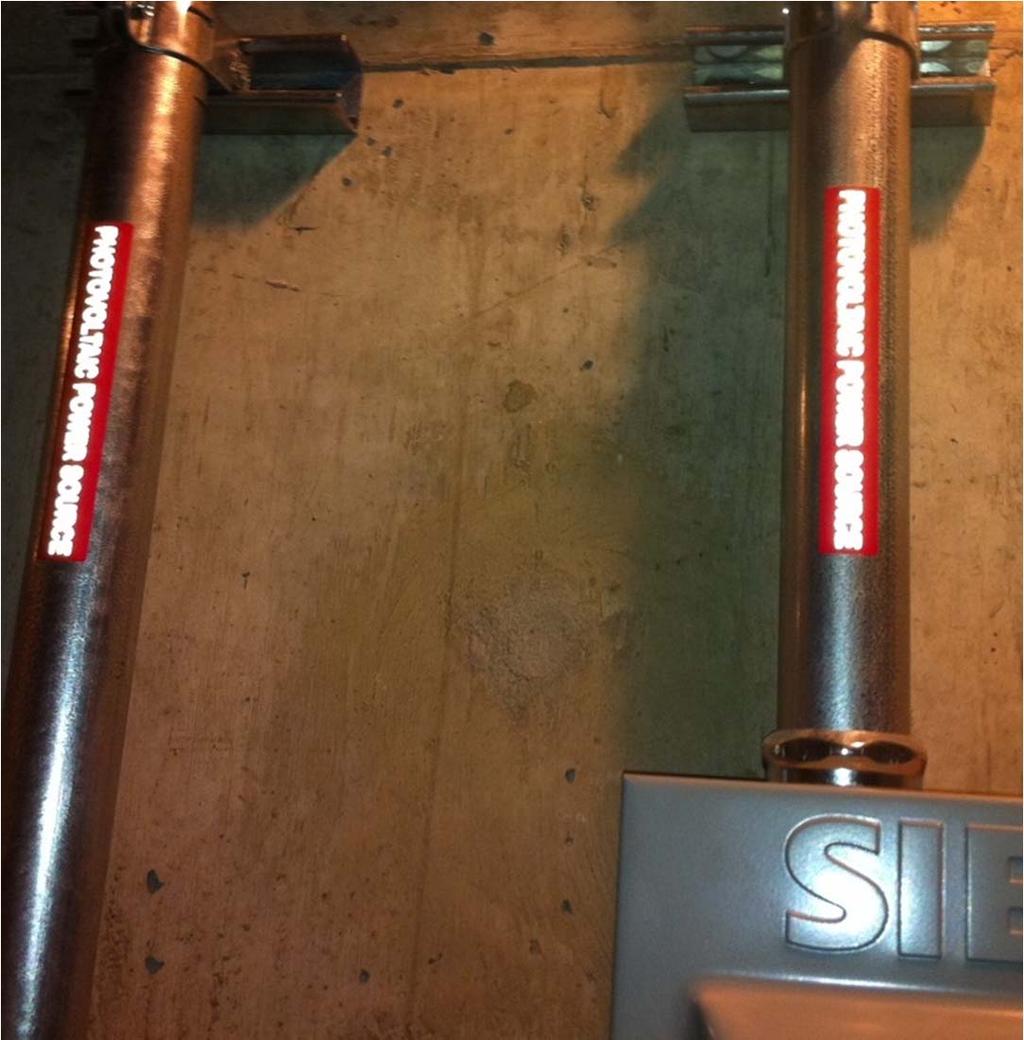
8 NEC (E)(3)(4) IFC & CAL FIRE 1.0 IFC : Marking shall be reflective. IFC : Marking shall be placed on all interior and exterior DC conduit, raceways, enclosures, and cable assemblies every 10 feet (3048mm) within 1 foot (305mm) of all turns or bends and within 1 foot (305mm) above and below all penetrations for roof/ceiling assemblies and all walls and/or barriers. Marker must also be on the main service disconnect


9 Case Study Rondo Library ballasted roof system, 40 kw, in St Paul 9
 Circuit Routing: Where circuits are embedded in build-up, laminate, or membrane roofing materials not")
10 NEC Article (F) Circuit Routing: Where circuits are embedded in build-up, laminate, or membrane roofing materials not covered by PV modules and associated equipment, the location of circuits shall be clearly marked. 10
 As")


11 NEC Article (F) As interpreted by the International Association of Electrical Inspectors (IAEI) in their 2011 NEC handbook on page
12 Main Service Disconnect: Marking IFC This marking shall also be placed adjacent to the main service disconnect in a location clearly visible from the location where the disconnect is operated. 12

13 Marking CAL FIRE For residential applications: This reflective label to be placed within the main service disconnect unless operable with the service panel closed in which case the marking should be placed on the outside cover. For commercial applications: Place adjacent to the main service disconnect visible from a location where the lever is operated. Each PV system disconnecting means shall be permanently marked to identify it as a photovoltaic system disconnect. 13


14 Disconnect Markings: NEC (C)(2) Each PV system disconnecting means shall be permanently marked to identify it as a photovoltaic system disconnect. 14
15 NEC Article Disconnection of PV Equipment: If the equipment is energized from more than one source, the disconnecting means shall be grouped and identified. BREAKER 1 of 2 - ARRAY CB3 Variable text printed on label using a thermal transfer printer. 15
(7) Installation and Service of an")
16 NEC Article (C) or OSHA (F)(7) Installation and Service of an Array 16
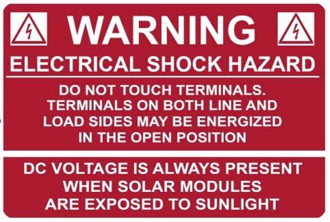
17 SECTION (F) The PV power source shall be labeled with the following warning at each junction box, combiner box, DC disconnect, and device where energized, ungrounded circuits may be exposed during service. Only needed for ungrounded systems 17
 Switch or Circuit Breakers Where all terminals of the disconnecting means may")

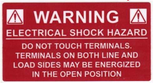
18 Section (4) Switch or Circuit Breakers Where all terminals of the disconnecting means may be energized in the open position, a warning label shall be mounted on or adjacent to the disconnecting means. Combiner Box or DC Breaker Box AC Breaker Box, main breaker panel Also NEC (4) for alternate power sources in general. 18

19 19 Section
 points of interconnection with other sources shall be marked at an")
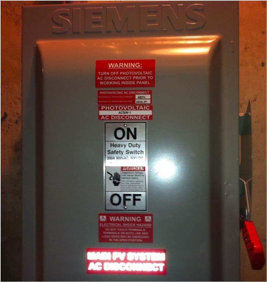
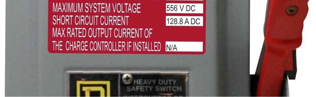
20 SECTION Interactive System Point of Interconnection All interactive system(s) points of interconnection with other sources shall be marked at an accessible location at the disconnecting means as a power source and with the rated AC output current and the nominal operating AC voltage. 20

21 21 AC Disconnect Before and After


22 Solar Labels This was an 8.4kw commercial job that passed inspection using pre-printed HellermannTyton Solar Installation labels. 22


23 23 Where are these labels applied?


 1 MAIN SERVICE DISCONNECT At the location of the ground-fault protection,")
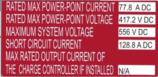
![normally at the inverter, warning of a shock hazard (NEC 690.5[C]). Per NEC 690.](/docs-images/73/68435618/images/24-10.jpg "52 Per NEC 690.17 (4) NEC690.")

 Per NEC 690.53 Per NEC 110.27(C) 24Per NEC 690.")

24 Materials used for marking shall be reflective, weather resistant, and suitable for the environment. IFC The markings shall be of sufficient durability to withstand the environment involved. NEC AC Disconnect / Breaker / Points of Connection Per NEC (C)(2) & Inverter Net Meter 3 Building/Structure Per NEC DC Disconnect/Breaker Per NEC 690.5(C) 1 MAIN SERVICE DISCONNECT At the location of the ground-fault protection, normally at the inverter, warning of a shock hazard (NEC 690.5[C]). Per NEC Per NEC (4) NEC690.4(F) Where circuits are embedded under roofing and not covered by PV modules, they shall be clearly marked. 4 Main Service 4 Breaker Panel/ Disconnect Pull Boxes Per NEC690.14(2) Per NEC Per NEC (C) 24Per NEC (F) DC conduit, raceways, enclosures, cable assemblies and junction boxes. Use every 10, at every turn, above and below penetrations, and all DC combiner junction boxes per IFC & NEC (E)(3). Per NEC (D)(4) & NEC Per NEC690.33(E)(2) Conductors at switch or circuit breakers (pull boxes) per NEC Main circuit breaker panel and meter per NEC , Dual power source NEC (D)(4) and Back-Fed Breakers per NEC and NEC Per NEC (4)

25 25 Easy to Use Quick to Apply
26 Cable Management to Article of the National Electrical Code Routing and Protecting PV Cables Article 334 cable routing requirements from the NEC 2011 Edition General overview of industry routing Routing updates and requirements for article 334 Best practices for routing and protecting PV cables Todd Fries Marketing Manager ID Systems Brian Ray Marketing Development Manager
27 NEC Nonmetallic-sheathed cable shall be supported and secured by staples, cables ties, straps, hangers, or similar fittings designed and installed so as not to damage the cable, at intervals not exceeding 1.4M (4-1/2 ft) and within 300mm (12 ) of every outlet box, junction box, cabinet, or fitting. Flat cables shall not be stapled on edge. Sections of cables protected from physical damage by raceway shall not be required to be secured within the raceway. 27
28 Bundling and Securing Cable management is one of the quickest ways to read the competence of the installation team or contractor. Conductors should be as close to invisible as possible. Using the correct material is an important factor. Cable tie material should be applicable to the environment where it is being used. There is more than one way to secure cables. 28
29 Common Cable Management Mistakes Wrong cable management material is used. Cable ties are pulled too tight or mounted on cut points. Not enough supports to properly support the cables. Cables touching an abrasive surface or mounted on a cut point. Plug connectors are not fully engaged. Very sloppy cable management. 29
30 Cable Management Solutions Use the proper material Cable ties must be UV stabilized. Cable ties must have the proper temperature rating at least -40 F to 225 F. Cable ties must be suitable for outdoor use. Stainless steel is acceptable, but be aware that it can be sharp. Watch the use of Nylon 6.6 with galvanized steel. 30

31 Cable Management Solutions Recommendations Nylon 66 UV stabilized cable ties. Specially designed for the solar industry. Available in a variety of lengths, tensile strengths and bundle diameters. Must have 2% carbon to be UV stabilized. 31
32 Cable Management Solutions Solar E-Clips are designed specifically to route cables by securing them to a metal or plastic frame rail edge, eliminating the need for mounting holes and mechanical fasteners. Clip is easy to secure. Clip has high-extraction force. Ensures long-term reliability. 32


33 Cable Management Solutions Recommendations Nylon 6.6 HIRHSUV Nylon 6.6 Impact Modified Heat Stabilized UV Stabilized 33

34 Cable Management Solutions Product Features and Benefits Integrated design allows for easy insertion by hand. Curved ends that prevent the clip from chaffing and damaging the PV cable. Double-compression design that accommodates various sizes of wire and cable. Manufactured of corrosion-resistant 304 stainless steel. Requires no installation tools, speeding up installing time. Accommodates single or multiple cables. Fits up to 1-3 mm in thickness. Presents a high extraction force for withstanding extreme conditions. 34
Photovoltaic (Solar) Array Installation Guide
 Array Installation Guide") Building & Safety Division Community Development Department 7351 Rosanna Street, Gilroy, CA 95020 Phone: 408 846-0451 Fax: 408 846-0429 Visit us: www.cityofgilroy.org Photovoltaic (Solar) Array Installation
Building & Safety Division Community Development Department 7351 Rosanna Street, Gilroy, CA 95020 Phone: 408 846-0451 Fax: 408 846-0429 Visit us: www.cityofgilroy.org Photovoltaic (Solar) Array Installation
SECTION SOLAR PHOTOVOLTAIC (PV) POWER GENERATION SYSTEM
 POWER GENERATION SYSTEM") SECTION 48 14 14 SOLAR PHOTOVOLTAIC (PV) POWER GENERATION SYSTEM PART 1 GENERAL 1.1 SECTION INCLUDES The work of this section consists of furnishing a complete Solar Photovoltaic (PV) Power Generation
SECTION 48 14 14 SOLAR PHOTOVOLTAIC (PV) POWER GENERATION SYSTEM PART 1 GENERAL 1.1 SECTION INCLUDES The work of this section consists of furnishing a complete Solar Photovoltaic (PV) Power Generation
A. Product Data: For each electrical identification product indicated. B. Comply with 29 CFR and 29 CFR
 September 2012, rev. 00 26 0553 Identification for Electrical Systems PART 1. GENERAL 1.01 Summary A. Section Includes: 1.02 Submittals 1. Identification for raceways. 2. Identification of power and control
SECTION ELECTRICAL IDENTIFICATION
 SECTION 16075 - ELECTRICAL IDENTIFICATION PART 1 - GENERAL 1.1 RELATED DOCUMENTS A. Drawings and general provisions of the Contract, including General and Supplementary Conditions and Division 1 Specification
SECTION C. Section Cable Trays for Electrical Systems: Additional identification requirements for cable tray systems.
 SECTION 26 0553 PART 1 GENERAL 1.1 SECTION INCLUDES A. Electrical identification requirements. B. Identification nameplates and labels. C. Wire and cable markers. D. Voltage markers. E. Underground warning
Developed by CA Matt Paiss, and Bill Brooks, PE
 Understanding the Cal Fire Solar Photovoltaic Installation Guideline Developed by CA Matt Paiss, and Bill Brooks, PE Presentation Overview Brief Overview of History of PV Firefighter Issues State Fire
SECTION IDENTIFICATION FOR ELECTRICAL SYSTEMS
 SECTION 260553 IDENTIFICATION FOR ELECTRICAL SYSTEMS PART 1 - GENERAL 1.1 SECTION INCLUDES A. Nameplates and labels B. Wire and cable markers C. Conduit markers 1.2 REFERENCES A. NFPA 70 - National Electrical
IDENTIFICATION FOR ELECTRICAL SYSTEMS July Electrical Systems
 SECTION 26 05 54 IDENTIFICATION FOR ELECTRICAL SYSTEMS PART 1 - GENERAL 1.1 SUMMARY A. Section Includes: 1. Nameplates. 2. Labels. 3. Wire markers. 4. Conduit markers. 5. Permanent Marking. 6. Underground
SECTION LOW-VOLTAGE ELECTRICAL POWER CONDUCTORS AND CABLES (600 VOLTS AND BELOW)
") SECTION 26 05 21 PART 1 - GENERAL 1.1 DESCRIPTION This section specifies the furnishing, installation, and connection of the low voltage power and lighting wiring. 1.2 RELATED WORK A. Excavation and backfill
SECTION 26 05 21 PART 1 - GENERAL 1.1 DESCRIPTION This section specifies the furnishing, installation, and connection of the low voltage power and lighting wiring. 1.2 RELATED WORK A. Excavation and backfill
Tyco Electronics Solar Identification Labels
 Tyco Electronics Solar Identification Labels 2010 Tyco Electronics Corporation. All Rights Reserved TE logo and Tyco Electronics are trademarks. Other products, logos and Company names mentioned herein
SECTION (16075) - IDENTIFICATION FOR ELECTRICAL SYSTEMS
 - IDENTIFICATION FOR ELECTRICAL SYSTEMS") SECTION 26 05 53 (16075) - IDENTIFICATION FOR ELECTRICAL SYSTEMS PART 1 GENERAL 1.01 SUMMARY A. Section Includes: 1. Electrical identification materials and devices required to comply with ANSI C2, NFPA
SECTION 26 05 53 (16075) - IDENTIFICATION FOR ELECTRICAL SYSTEMS PART 1 GENERAL 1.01 SUMMARY A. Section Includes: 1. Electrical identification materials and devices required to comply with ANSI C2, NFPA
SECTION AUTOMATIC TRANSFER SWITCHES PART 1 - GENERAL
 SECTION 16400 AUTOMATIC TRANSFER SWITCHES 1.01 RELATED DOCUMENTS PART 1 - GENERAL A. Drawings and general provisions of Contract, including General Conditions and Division 1 Specification sections, apply
Revisions for the 2011 National Electrical Code - Part 4
 PDHonline Course E358 (3 PDH) Revisions for the 2011 National Electrical Code - Part 4 Instructor: Patrick Ouillette 2012 PDH Online PDH Center 5272 Meadow Estates Drive Fairfax, VA 22030-6658 Phone &
SECTION PANELBOARDS. A. Drawings and general provisions of the Contract, including General and Supplementary Conditions, apply to this Section.
 PART 1 - GENERAL 1.1 RELATED DOCUMENTS A. Drawings and general provisions of the Contract, including General and Supplementary Conditions, apply to this Section. 1.2 SUMMARY A. This Section includes the
LINEAR HEAT DETECTION CABLE DURÁN-SAFE
 LINEAR HEAT DETECTION CABLE DURÁN-SAFE Installation & User Manual 2017 DURAN ELECTRONICA S.L. - All rights reserved www.duranelectronica.com TABLE OF CONTENTS pages 1. INTRODUCTION...5 2. FUNCTIONING...5
NATIONAL ELECTRICAL CODE (NEC) & NFPA 70E ARC FLASH ELECTRICAL SAFETY
 & NFPA 70E ARC FLASH ELECTRICAL SAFETY") A new twist on the National Electrical Code - a practical application workshop. If you sign up in this class, prepare to work! Day 1: Fundamentals of OSHA requirements for performing electrical work -
A new twist on the National Electrical Code - a practical application workshop. If you sign up in this class, prepare to work! Day 1: Fundamentals of OSHA requirements for performing electrical work -
8. Multi-Family Residential Buildings
 Mu lti-f a mily Re s id e n tia lbu ild in g s 2016 Electric Service Requirements, 3rd Edition Section 8 Section 8 Multi-Family Residential Buildings Directory Page 8.1 General 61 8.2 Maximum Available
Fire Alarm Systems ARTICLE. Introduction to Article 760 Fire Alarm Systems. Part I. General
 ARTICLE 760 Fire Alarm Systems Introduction to Article 760 Fire Alarm Systems Article 760 covers the installation of wiring and equipment for fire alarm systems, including all circuits controlled and powered
A. Shop Drawing submittals shall include, but not be limited to, the following:
 SECTION 26 05 53 IDENTIFICATION FOR ELECTRICAL SYSTEMS PART 1 - GENERAL 1.1 RELATED DOCUMENTS: A. The Conditions of the Contract and applicable requirements of Divisions 0 and 1 and Section 26 00 01, Electrical
Installation Instructions
 Installation Instructions 3M Light Mat Series 3635-1000 Installation Bulletin 3635-1000 Release D, Effective July 2010 (Replaces C, Apr 2010) See Bulletin Change Summary at end of Bulletin Product Description
PERMIT APPLICATION REQUIREMENTS FOR NON-RESIDENTIAL ROOF MOUNTED PHOTOVOLTAIC SYSTEMS
 Butte County Department of Development Services PERMIT CENTER 7 County Center Drive, Oroville, CA 95965 Main Phone (530)538-7601 Permit Center Phone (530)538-6861 Fax (530)538-7785 FORM NO DBP-73 PERMIT
Arctica Solar 1500 Series Heater Installation Manual
 Arctica Solar 1500 Series Heater Installation Manual A wall mounted Arctica Solar 1500 series solar heater + PV panel demonstration wall The 1500 Series Solar Air Heater from Arctica Solar is designed
LINEAR HEAT DETECTION CABLE DURÁN-SAFE
 LINEAR HEAT DETECTION CABLE DURÁN-SAFE Installation & User Manual 2018 DURAN ELECTRONICA S.L. - All rights reserved www.duranelectronica.com I-manSAFECABLE-v05 TABLE OF CONTENTS Pages 1. INTRODUCTION...
Michigan Chapter IAEI Annual Meeting Ann Arbor, Michigan Code Panel Questions December 5 th and 6 th, 2013
 Michigan Chapter IAEI Annual Meeting Ann Arbor, Michigan Code Panel Questions December 5 th and 6 th, 2013 1. Is a standard wire-nut approved for a wet location as in an outside j-box? Is there a listed
BUILDING PERMIT APPLICATION REQUIREMENTS FOR GROUND MOUNTED PHOTOVOLTAIC SYSTEMS
 Butte County Department of Development Services PERMIT CENTER 7 County Center Drive, Oroville, CA 95965 Main Phone (530) 538-7601 Permit Center Phone (530) 538-6861 Fax (530) 538-7785 FORM NO DBP-70 BUILDING
SECTION AUTOMATIC TRANSFER SWITCHES
 PART 1 - GENERAL 1.1 DESCRIPTION SECTION 26 36 23 This section specifies the furnishing, complete installation, and connection of automatic transfer switches. 1.2 RELATED WORK A. Section 14 21 00, ELECTRIC
SUMMARY OF CALIFORNIA FIRE MARSHAL SOLAR PHOTOVOLTAIC INSTALLATION GUIDELINE. Presented by Bill Brooks, PE Brooks Engineering
 SUMMARY OF CALIFORNIA FIRE MARSHAL SOLAR PHOTOVOLTAIC INSTALLATION GUIDELINE Presented by Bill Brooks, PE Brooks Engineering How the State Guideline Process Started Many installation permits began being
PV Standards Activities SEIA Codes and Standards Workshop. Scott Jezwinski Business Development Manager Sep 12, 2016
 PV Standards Activities SEIA Codes and Standards Workshop Scott Jezwinski Business Development Manager Sep 12, 2016 Codes and Standards - Relationship Model Code Development Process Step 1: First Draft
SECTION (16140) - WIRING DEVICES
 - WIRING DEVICES") SECTION 26 27 26 (16140) - WIRING DEVICES PART 1 GENERAL 1.01 SUMMARY A. Section Includes: 1. Receptacles, Connectors, Switches, and Finish Plates. B. Related Sections: 1. Section 00 31 13.43 (00370) -
SECTION 26 27 26 (16140) - WIRING DEVICES PART 1 GENERAL 1.01 SUMMARY A. Section Includes: 1. Receptacles, Connectors, Switches, and Finish Plates. B. Related Sections: 1. Section 00 31 13.43 (00370) -
Dome Fiber Optic Closure SC-221
 Dome Fiber Optic Closure SC-221 General Information SC-221 fiber optic closure protects the fiber optic splices from harsh external environment conditions. It is designed for many network segments and
Section 5.0: HAZARDOUS MATEIRAL STORAGE TABLE OF CONTENTS. A. Regulations, Standards and References 2. B. Scope 3. C. Approvals and Listings 3
 Section 5.0: HAZARDOUS MATEIRAL STORAGE TABLE OF CONTENTS A. Regulations, Standards and References 2 B. Scope 3 C. Approvals and Listings 3 D. Design 4 E. Venting Cabinets 4 Page F. General Installation
J-PRO TM Cable Support System
 Frequently Asked Questions Cable Support System What references define how and where J-hooks are used? J-hooks are a horizontal pathway promoted in the BICSI TDM manual as a means to route small to medium
Type approval qualification of Photovoltaic Modules Procedures and test experiences
 Type approval qualification of Photovoltaic Modules Procedures and test experiences We Advise. Develop. Facilitate. Inspect. Certificate. Precisely Right. For You. 1 Type approval qualification of Photovoltaic
Introducing Solar Identification Labels
 Introducing Solar Identification Labels Solar Identification Labels KEY FEATURES Recommended for use in identification of DC Disconnects and Inverters. For use on painted smooth metal and textured metal
SECTION AUTOMATIC TRANSFER SWITCHES
 PART 1 - GENERAL 1.1 DESCRIPTION SECTION 26 36 23 SPEC WRITER NOTE: Use this section only for NCA projects. Delete between //--// if not applicable to project. Also, delete any other item or paragraph
Article 393 Low Voltage Suspended Ceiling Power Distribution System
 Article 393 Low Voltage Suspended Ceiling Power Distribution System IAEI Eastern Section Meeting Annapolis, MD October 8,2014 Jack Lyons NEMA Northeast Field Rep Ben Franklin was right on!! If there is
SECTION INTERIOR LIGHTING
 SECTION 26 51 00 INTERIOR LIGHTING PART 1 - GENERAL 1.1 RELATED DOCUMENTS A. Drawings and general provisions of the Contract, including General and Supplementary Conditions and Division 01 Specification
Electrical Tech Note 107
 Electrical Tech Note 107 Biosystems & Agricultural Engineering Department Michigan State University Understanding the Construction Code Rules, Part 8 1 Based on the 2014 NEC and the 2015 MRC The State
Double insulated, electron-beam cross-linked, halogen free photovoltaic wire sunlight resistant. Single conductor, flame retardant insulation.
 Technical Data Sheet BETAflam Solar 125 flex UL 4703 Description Double insulated, electron-beam cross-linked, halogen free photovoltaic wire sunlight resistant. Single conductor, flame retardant insulation.
*************************************************************************** SECTION D50 ELECTRICAL 02/18
 NAVFAC PTS-D50 (February 2018) -------------------------------- Preparing Activity: NAVFAC SUPERSEDING PTS D50 (September 2016) PERFORMANCE TECHNICAL SPECIFICATION SECTION D50 ELECTRICAL 02/18 NOTE: This
Special Provision No. 682S27 June This Special Provision refers to the following standards, specifications or publications:
 CONTROLLER CABINETS, POLE MOUNTED - Item No. Special Provision No. 682S27 June 2017 1. SCOPE This Special Provision covers the requirements for the installation of pole mounted controller cabinets and
INSTALLATION INSTRUCTIONS
 INSTALLATION INSTRUCTIONS Electric Heat Sections Used with Blower Coil Units ELECTRIC HEAT SECTIONS 505,084M (0655012-30) 05/15 Supersedes 09/11 Litho U.S.A. NOTICE TO INSTALLER IT IS HIGHLY RECOMMENDED
IMPROVE SAFETY WITH ARC FLASH LABELING COMPLY WITH THE 2015 NFPA 70E REGULATIONS
 IMPROVE SAFETY WITH ARC FLASH LABELING COMPLY WITH THE 2015 NFPA 70E REGULATIONS By Thomas Smith, Product Specialist, Brady Corporation Last updated: February, 2015 The Occupational Safety and Health Administration
IMPORTANT NOTICE BUILDERS AND CONTRACTORS WORKING IN NORTH RICHLAND HILLS, TEXAS. June 17th, 2016
 IMPORTANT NOTICE BUILDERS AND CONTRACTORS WORKING IN NORTH RICHLAND HILLS, TEXAS June 17th, 2016 RE: City Council Adopts 2014 National Electrical Code with Pool Alarm Requirements On April 25th, 2016 the
FRP HEATING SYSTEM INSTALLATION, OPERATION & MAINTENANCE MANUAL FRP.IOM.R1
 FRP HEATING SYSTEM INSTALLATION, OPERATION & MAINTENANCE MANUAL FRP.IOM.R1 Hotfoil, Inc. Robbinsville, NJ 08691 Phone: 609.259.4118 / Fax : 609.259.4119 http://hotfoil.com TABLE OF CONTENTS I Product Specification
VACUUM BREAKER MEDIUM VOLTAGE AUTOMATIC TRANSFER SWITCHES
 Part One General 1.01 Scope A. It is the intent of this specification to provide a medium voltage automatic transfer system. B. All components, testing and services specified and required for a complete
ELECTRIC and NEON SIGN STANDARDS. By Randy Wright RKW CONSULTING
 SEMINAR 301 Part 1: Changes in the 2005 NEC SEMINAR RULES: There are no Rules All Questions need to be asked Stop at any time for an explanation SEMINAR PARTS: ELECTRIC and NEON SIGN STANDARDS By Randy
ELECTRICAL - WIRING DESIGN AND PROTECTION SELF INSPECTION CHECKLIST
 Name of School: OPTIONAL INFORMATION Date of Inspection: Vocational Program/Course/Room: Signature of Inspector: ELECTRICAL - WIRING DESIGN AND PROTECTION SELF INSPECTION CHECKLIST Guidelines: This checklist
Renewable Energy. System Solutions
 System Solutions Locally manufactured to global standards HellermannTyton offers a tailor made String Combiner Box (SCB) manufacturing service. Based on the customer requirements HellermannTyton will design
Leakage Detection. WaterAlarmSystems Fuel-oil/WaterAlarms. Safe protection for plants and buildings...leakage Detection Systems provided by BARTEC
 Leakage Detection WaterAlarmSystems Fuel-oil/WaterAlarms Safe protection for plants and buildings...leakage Detection Systems provided by BARTEC Reservation Technical data is subject to change without
NFPA 70E Edition Update
 NFPA 70E- 2018 Edition Update Paul Colangelo- STSC, CHST, CET, CRIS National Director of Compliance Programs ClickSafety 1 ASSE Construction Practice Specialty Quarterly Meeting 11/17/2017 Agenda Overview
Short Circuit Current Rating
 Short Circuit Current Rating Customer Need There has been a significant increase in the misapplication of control panel products that brings into question the safety of those installing and using this
UNIFIED FACILITIES GUIDE SPECIFICATIONS
 USACE / NAVFAC / AFCEC / NASA UFGS-23 83 00.00 20 (April 2006) -------------------------------- Preparing Activity: NAVFAC Replacing without change UFGS-15768N (September 1999) UNIFIED FACILITIES GUIDE
Get it Right the First Time Avoid These Commonly Cited Errors
 May 2014 Get it Right the First Time Avoid These Commonly Cited Errors By Mark Earley and Mark Hilbert Copyright 2014 National Fire Protection Association. All rights reserved. Good electrical contractors
Contractor Information Packet. North County Fire Authority. 10 Wembley Drive Daly City, CA (650)
") North County Fire Authority Contractor Information Packet North County Fire Authority 10 Wembley Drive Daly City, CA 94015 (650) 991-8138 TABLE OF CONTENTS Access for Firefighting Equipment...2 Fire Safety
North County Fire Authority Contractor Information Packet North County Fire Authority 10 Wembley Drive Daly City, CA 94015 (650) 991-8138 TABLE OF CONTENTS Access for Firefighting Equipment...2 Fire Safety
! The Caution Symbol (exclamation point) alerts you to a "CAUTION", a safety or
 alerts you to a CAUTION, a safety or") I&M NUMBER: 316-42-10-1 Page: 1 Pre Installation Check to make sure that heater received is the same as that ordered. Elements may come in contact with each other during shipment. Minor adjustments to
I&M NUMBER: 316-42-10-1 Page: 1 Pre Installation Check to make sure that heater received is the same as that ordered. Elements may come in contact with each other during shipment. Minor adjustments to
CATALOG LIQUID-TUFF FLEXIBLE LIQUIDTIGHT CONDUIT CATALOG. Industrial & Commercial Liquidtight Conduit Flexible Metal Conduit A PART OF
 CATALOG LIQUID-TUFF FLIBL LIQUIDTIGHT CONDUIT CATALOG Industrial & Commercial Liquidtight Conduit Flexible Metal Conduit A PART OF AFC s Flexible Liquidtight Conduit AFC Cable Systems is pleased to announce
WATLOW IND. WATROD Circulation Heater Installation & Maintenance Manual I&M NUMBER: Page: 1 Date: 6/11/2008 Rev: 2.00
 I&M NUMBER: 316-42-5-1 Page: 1 Pre Installation Check to make sure that heater received is the same as that ordered. Watlow heaters are built to comply with UL and CSA dielectric requirements, it may be
.4 Do complete installation in accordance with latest Electrical Bulletins of the local inspection authority.
 Fitness Facility Addition Page 1 1.1 CODES AND STANDARDS.1 Do complete installation in accordance with the latest edition of the CSA C22.1 as amended by the latest editions of the National Building Code
ThermoCable Linear Heat Detection System
 ThermoCable Linear Heat Detection System Estimating Guide 1. INTRODUCTION 1.1 Linear Heat Detection ThermoCable digital linear heat detection wire is a combination of advanced polymer and digital technologies
SECTION RADIANT-HEATING ELECTRIC CABLES PART 1 - GENERAL 1.1 SECTIONS INCLUDES
 SECTION 238313 - RADIANT-HEATING ELECTRIC CABLES PART 1 - GENERAL 1.1 SECTIONS INCLUDES A. Low-voltage Electric Snow and ice heating elements "under" finished roof materials (shingles or metal), gutters,
PHOTOVOLTAIC CABLES. Photovoltaic Cable 2000V/1500V Photovoltaic Cable 2000V/1000V
 PHOTOVOLTAIC CABLES PHOTOVOLTAIC CABLES INDEX n AmerSol Dual-Certified (UL / ETL) Photovoltaic Cable 2000V/1500V....................... 2-3 n AmerSol Dual-Certified (UL / ETL) Photovoltaic Cable 2000V/1000V.......................
Gardian W51. Approvals
 Gardian W51 120 V pre-assembled electric heating cables for pipe freeze protection and roof & gutter de-icing Installation Instructions Description Gardian W51 120 V pre-assembled self-regulating heating
IDENTIFYING TRAY CABLES FOR YOUR NEXT INSTALLATION A WHITE PAPER
 IDENTIFYING TRAY CABLES FOR YOUR NEXT INSTALLATION A WHITE PAPER Published 3/23/2012 T hough rapidly increasing in popularity, tray cables are still a point of confusion for many. While the term tray cable
SECTION RADIANT-HEATING ELECTRIC CABLES / MATS
 SECTION 238313- RADIANT-HEATING ELECTRIC CABLES / MATS PART 1 - GENERAL 1.1 SECTION INCLUDES A. Electric radiant snow melting mats or cables embedded in concrete or asphalt slabs, or embedded under brick
SECTION ISOLATED POWER SYSTEMS
 PART 1 - GENERAL 1.1 DESCRIPTION SECTION 26 20 11 ISOLATED POWER SYSTEMS SPEC WRITER NOTE: Delete between //---// if not applicable to project. Also, delete any other item or paragraph not applicable to
WATLOW IND. WATROD Flange Heater Installation & Maintenance Manual I&M NUMBER: Page: 1 Date:6/11/2008 Rev: 2.00
 I&M NUMBER: 316-42-8-1 Page: 1 _ Pre Installation Check to make sure that heater received is the same as that ordered. Elements may come in contact with each other during shipment. Minor adjustments to
Roof Mounting System. Installation Manual. Standard (XRS) and Light (XRL) Rails with Integrated Grounding *ETL Listed Per UL Edition v1.
 and Light (XRL) Rails with Integrated Grounding *ETL Listed Per UL Edition v1.") Roof Mounting System Standard (XRS) and Light (XRL) *ETL Listed Per UL2703 2013 Edition v1.1 A complete manual for the installation of IronRidge s rail systems with integrated grounding. This Installation
Roof Mounting System Standard (XRS) and Light (XRL) *ETL Listed Per UL2703 2013 Edition v1.1 A complete manual for the installation of IronRidge s rail systems with integrated grounding. This Installation
MASTERSPEC TECHNICAL SPECIFICATIONS DIVISION 28 ELEC. SAFETY & SECURITY SECTION CONDUCTORS AND CABLES FOR ELECTRONIC SAFETY AND SECURITY
 SECTION 280513 - CONDUCTORS AND CABLES FOR ELECTRONIC SAFETY AND SECURITY PART 1 - GENERAL 1.1 SUMMARY A. Section Includes: 1. Coaxial cabling. 2. RS-232 cabling. 3. RS-485 cabling. 4. Low-voltage control
Innovative Lighting R-Series Overhead LED Conversion Kits
 Installation Guide Innovative Lighting R-Series Overhead LED Conversion Kits For Commercial Walk-In Coolers and Freezers BEFORE YOU BEGIN INSTALLATION Read these instructions carefully. Failure to follow
MODEL FPT-130 SINGLE POINT FREEZE PROTECTION HEAT TRACE CONTROL
 TRACON MODEL FPT-130 SINGLE POINT FREEZE PROTECTION HEAT TRACE CONTROL TABLE OF CONTENTS FPT 130 Overview... 2 Installation... 3 Power Source and Load Connections... 4 Temperature Sensor... 5 External
INSTALLATION INSTRUCTIONS Model FH-2071-UM Enclosure
 INSTALLATION INSTRUCTIONS Model FH-2071-UM Enclosure Enclosure INTRODUCTION The Model FH-2071-UM Enclosure from., used in Marine applications is robust and weather-resistant. Its durable design is customized
UltraLITE Model ELU Centralized Emergency Lighting Inverter 4.2 KW- 5 KW
 12/23/16 Rev 9 UltraLITE Model ELU General Specification 4.2 KW to 5 KW UltraLITE Model ELU Centralized Emergency Lighting Inverter 4.2 KW- 5 KW 1.0 General General Specification This specification describes
SECTION ELECTRICAL GENERAL PROVISIONS
 PART 1 GENERAL 1.01 SECTION INCLUDES A. General provisions for Electrical Systems B. Wire and cable for 600 volts and less. C. Wiring connectors. D. Electrical tape. E. Heat shrink tubing. F. Wire pulling
EasyWire Between Joists Installation Instructions
 EasyWire Between Joists Installation Instructions General Our product, EasyWire, is intended to bring up the floor temperature to a comfortable condition (no cold feet). Read instructions carefully I.
WATLOW IND. FIREBAR Flange Heater Installation & Maintenance Manual I&M NUMBER: Page: 1 Date: 6/11/2008 Rev: 2.00
 I&M NUMBER: 316-42-2-1 Page: 1 Pre Installation Check to make sure that heater received is the same as that ordered. Elements may come in contact with each other during shipment. Minor adjustments to elements
SECTION PANELBOARDS Painting Wire and Cable Overcurrent Protective Devices.
 SECTION 16470 PANELBOARDS PART 1 GENERAL 1.01 SUMMARY A. Related Sections: 1. 09900 - Painting. 2. 16120 - Wire and Cable. 3. 16475 - Overcurrent Protective Devices. 1.02 SYSTEM DESCRIPTION A. Performance
NFPA 80 Overview January 21, 2016
 NFPA 80 Overview January 21, 2016 Kristin Bigda, P.E. Senior Fire Protection Engineer National Fire Protection Association Presenter Kristin Bigda, P.E. Senior Fire Protection Engineer, NFPA Building Fire
TOM BURNS, PLANNING DIRECTOR
 ~~ 0 173 COUNTY OF SANTA CRUZ August 4,2005 PLANNING DEPARTMENT 701 OCEAN STREET, qth FLOOR, SANTA CRUZ, CA 95060 (831) 454-2580 FAX: (831) 454-2131 TDD: (831) 454-2123 TOM BURNS, PLANNING DIRECTOR Agenda:
Installation GUIDE 6 SERIES. Built-in Electric Single and Double Wall Ovens MVSOE630 / CMVSOE630 MVDOE630 / CMVDOE630
 Installation GUIDE 6 SERIES Built-in Electric Single and Double Wall Ovens MVSOE630 / CMVSOE630 MVDOE630 / CMVDOE630 1 Table of Contents Warnings & Important Safety Information 2 Dimensions 4 Specifications
NEC 2017 Changes and Their Effect Upon the ICT Industry
 NEC 2017 Changes and Their Effect Upon the ICT Industry Today s Presenters John Kacperski, RCDD, OSP, CDT Chair of BICSI Standards BICSI Representative on NFPA 70-CMP 16 Richard S. Anderson, RCDD, CDT,
ONYX FirstVision Specification Interactive Firefighters Display
 ONYX FirstVision Specification Interactive Firefighters Display NOTIFIER is a registered trademark, and ONYX FirstVision, NOTI FIRE NET, and VeriFire are trademarks of Honeywell International Inc. Microsoft
Submittal Data Performance Data Electrical Data
 ERMS Series Submittal Data Submittal Data Unit Designation: Job name: Architect: Engineer: Contractor: Performance Data Revision: 07/01/11 Cooling Capacity: EER: Heating Capacity: COP: Ambient Air Temp:
Entry Level Assessment Blueprint Electrical Construction Technology
 Blueprint Electrical Construction Technology Test Code: 4230 / Version: 01 Specific Competencies and Skills Tested in this Assessment: Introduction to the Electrical Construction Technology Career Identify
IEC and NCCER Mapping for Year 1
 Craft: 26102-14 Safety IEC and NCCER Mapping for Year 1 Perform a visual inspection on various types of ladders 102.4 STATE GENERAL SAFETY CONSIDERATIONS IN ELECTRICAL INSTALLATIONS (LADDER SAFETY, SLECTION
Installation Guide. Heating cables. Pipe tracing. Intelligent solutions with lasting effect. Visit DEVI.com
 Installation Guide Heating cables Pipe tracing Intelligent solutions with lasting effect Visit DEVI.com Table of Contents 1 Introduction.................... 3 1.1 Safety Instructions...............3 1.2
2016 CDM Smith All Rights Reserved July 2016 SECTION FIBER OPTIC DATA NETWORK
 PART 1 GENERAL 1.01 SCOPE OF WORK SECTION 27 12 23 FIBER OPTIC DATA NETWORK A. Furnish, install, terminate, and test all fiber optic equipment and cabling necessary for a complete and functional data highway
A. Furnish and install wiring devices and plates as specified herein and as shown on the Drawings.
 DIVISION 26 ELECTRICAL SECTION 26 27 26 PART 1 GENERAL 1.01 DESCRIPTION A. Furnish and install wiring devices and plates as specified herein and as shown on the Drawings. B. Specialty switches and outlets
APPENDIX - L INTERNATIONAL RESIDENTIAL CODE ELECTRICAL
 This Appendix (2000 IRC Appendix-L) is produced, copyrighted, and maintained by the National Fire Protection Association Association, all rights reserved. Use of this Appendix is pursuant to license with
Solid State Lighting Sub-Assembly Interfaces for Luminaires. Andrew D. Jackson Philips Lighting Corporate Regulatory and Certification Laboratory
 NEMA White Paper - Recommendations for Solid State Lighting Sub-Assembly Interfaces for Luminaires i Andrew D. Jackson Philips Lighting Corporate Regulatory and Certification Laboratory CORM May 8, 2009
Overview of Significant 2017 NEC Changes
 Overview of Significant 2017 NEC Changes National Fire Protection Association. All rights reserved. Five New NEC Articles Article 426 Fixed Resistance and Electrode Industrial Heating Equipment Article
NORTHWESTERN UNIVERSITY PROJECT NAME JOB # ISSUED: 11/06/2018
 SECTION 26 2913 - ENCLOSED CONTROLLERS GENERAL 1.1 RELATED DOCUMENTS A. Drawings and general provisions of the Contract, including General and Supplementary Conditions and Division 01 Specification Sections,
WATLOW ELECTRIC MFG CO. FIREBAR Screw Plug Installation & Maintenance Manual I&M NUMBER: Page: 1 Date: 11/25/2013 Rev: 4.
 I&M NUMBER: 316-42-3-1 Page: 1 Pre Installation Check to make sure that heater received is the same as that ordered. Elements may come in contact with each other during shipment. Minor adjustments to elements
ASME Packaged Electric Water Heater
 MODEL SH & H ASME Packaged Electric Water Heater 15-1600 KW - All Voltages & Phases, 80-5000 Gallon Capacity Features Reliable Packaged System Only high grade materials used in construction to ensure long
Innovative Lighting R-Series Vertical Refrigeration
 Installation Guide Innovative Lighting R-Series Vertical Refrigeration Door LED Conversionn Kits For Commercial Refrigerators and Freezers BEFORE YOU BEGIN INSTALLATION Read these instructions carefully.
TABLE OF CONTENTS CHAPTER 2 WIRING AND PROTECTION CHAPTER 1 GENERAL RULES... 19
 TABLE OF CONTENTS About This Textbook...xi How to Use the National Electrical Code... 1 Article 90 Introduction to the National Electrical Code... 7 90.1 Purpose of the NEC... 7 90.2 Scope of the NEC...
Sundance Spas SPA EQUIPMENT SYSTEM. Installation Instructions. P/N Rev. A
 Sundance Spas SPA EQUIPMENT SYSTEM Installation Instructions P/N 6530-456 Rev. A Contents Important Notices 1 Important Safety Instructions 2 Where to Place the Equipment System 3 Connecting Pipes Between
9/7/2010. Chapter , The McGraw-Hill Companies, Inc. AND BONDING. 2010, The McGraw-Hill Companies, Inc.
 Chapter 1 GROUNDING AND BONDING 1 Proper grounding practices protect people from the hazards of electric shock and ensure the correct operation of overcurrent protection devices. Grounding is the intentional
UNIFIED FACILITIES GUIDE SPECIFICATIONS
 USACE / NAVFAC / AFCEC / NASA UFGS-21 21 03.00 10 February 2009) ---------------------------------- Preparing Activity: USACE Superseding UFGS-21 21 03.00 10 (April 2006) UNIFIED FACILITIES GUIDE SPECIFICATIONS
COMMON WORK RESULTS FOR ELECTRICAL: Basic Electrical Materials Methods
 1. BASIC ELECTRICAL MATERIALS 1. All conduit and raceway must be 3/4" or larger. Exposed raceway in finished areas shall be in 700 or larger wiremold. Exception: runs to individual devices 10 or less,