Model OEM-2 INSTRUCTIONS FOR USE
|
|
|
- Brianne Bryant
- 6 years ago
- Views:
Transcription
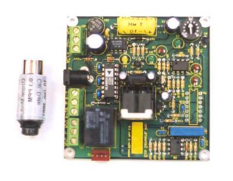
1 ECO SENSORS, INC OEM OZONE CONTROLLER Model OEM-2 INSTRUCTIONS FOR USE GENERAL The model OEM-2 is a system to control ozone generators and alarms based on an adjustable ozone concentration set point. It is designed to work with plug-in sensor modules for ppm, 0-1 ppm, and 0-10 ppm. These are specified when ordering by putting the ppm range after the model number. For example, a 0.1 ppm OEM-2 board system would be OEM-2-.1 and the replacement sensor module for it would be SM These same sensor modules also work in our OEM-1 boards, which have features such as being powered by 110/220 VAC. The sensors modules can also be located at a distance from the OEM-2 boards by 2 or 8 meter cables. These are readily available DIN M/F 5 pin extension cables. One component of the OEM-2 system is the base board which incorporates the power supply, final signal processing, set-point controls, and the output relay. The other component is the sensor mounted with its associated electronics in a cylindrical DIN plug. This is precalibrated in our lab so that the sensor module and main board module together work as a calibrated system. If the sensor module is damaged, it is simply replaced by another precalibrated module. The design incorporates hysteresis and time delay (set at 8 seconds except for special orders) to eliminate chatter and other excessive interactions between the sensor and generator. The SPDT relay contacts will handle up to 5 amps at 250 volts. The OEM-2 should not be used outdoors or in the presence of NOx, nitric acid, acid gases, or halogen compound fumes. Allow warm-up according to the table below. At least 24 hours is recommended if the system hasn't been used for a week or so. This is because the sensor can absorb VOCs when it is not in use. OPTIONS In addition to the basic switching function, the OEM-2 may be ordered with the following: 1. An analog voltage output which is a buffered version of the sensor module signal. Again, one volt of output represents the calibration of the sensor module. 2. A 4-20 ma current output which is proportional to the sensor module s output. 3. A driver circuit for an audible alarm, including an acknowledge switch input to silence this alarm. The alarm will turn on again after the ozone level drops below the switch threshold and then rises again and 8 meter extension cables are available for remote mounting of the sensor module. Note that the use of these cables unavoidably introduces a small offset voltage, which is added to the sensor output. This will raise the zero point by an amount which is not usually significant.
2 2 INSTALLATION CAUTION! It is best to bench test the board with an AC adapter 12 VDC supply (see below). Do not let solder connections on the OEM-2 board short circuit to any metal surfaces. The OEM-2 should be attached to your equipment (such as inside the ozone generator) by four mounting holes. Select four that align with your equipment and which stabilize the OEM board. The board surface on the solder side should be kept at least 6 mm (1/4") from any metal surface. The OEM-2 board should be wired to your power by the terminal block terminals 2 and 3 for 110 V 60 Hz or 220 V 50 Hz according to the power transformer wiring/jumper diagram found in these instructions. Alternately, you can power the unit by 12 V DC via jack J2. This low voltage power option was provided especially for bench testing the OEM-2 without exposing personnel to high line voltages. The Eco Sensors P-20 AC adapter (a purchase option) can be used to provide 12 VDC when 120 VAC 60 HZ is available. For 220 V 50 Hz power, you will have to purchase an adapter locally with specifications according to our Tech Note P-101. CONNECTIONS Along one edge of the OEM-2 board are three 3-position terminal blocks. These are labeled in silk-screen on the board as TB-1, TB-2 and TB-3. TB-1, located at the front of the board (i.e. closest to the sensor module) is the relay output, which is capable of switching up to 5 amps at 250 V. TB-2 provides the 4-20 ma and 0-2 Volt analog outputs, if these options have been installed. TB-3, farthest from the sensor module, is the board s power input. Any supply from Volts AC or DC is acceptable, with a current drain of approximately ma. To operate the board from AC power, connect the supply leads to the two outside screws of TB-3. DC power may be applied between either of the outside screws and the center screw (the center screw is board ground and MUST be the negative side of the DC supply). Note that when powered from AC, the board s circuit ground is NOT connected directly to either supply lead. For convenience, a DC power input connector is located between TB-2 and TB-3. An Eco Sensors model P-20 power adapter (or equivalent VDC source) may be plugged into this connector to power the board. Do NOT use this option when power is being applied via TB-3. WARM-UP When the generator or other equipment is turned off, if possible, it is best to wire the units so that the OEM-2 board is always powered. The sensor will stay heated and burn off any chemicals it would otherwise absorb. When the ozone generator or other equipment is turned back on, the OEM board is ready to respond immediately and accurately. Otherwise, warm-ups are required. Recommended warm-up times are: Time Since Last Powered Warm-up Time 1 minute - 3 days 10 minutes 3-7 days 1 hour More than 1 week 24 hours
3 3 If the sensor is easily accessible, the warm-up time can be minimized by checking for full response by an ozone generator of known output. The Eco Sensors OG-2 Ozone Source Calibrator is a portable battery-operated source which is designed to check for response at 0.1 ppm. OPERATION The OEM-2 is calibrated at the factory by comparison with a NIST traceable UV analyzer. Lower detection points can be set by the calibrated dial pot R-14 on the main board. Its numbers represent percentage of ppm. For example, 50 on the dial pot is 50% of 0.1 or 0.05 ppm (50 ppb). The calibration as a percentage of 0.1 ppm should be within 20% over ppm. We do not recommend operating with a set point for detection below 0.03 ppm because too many chemical, atmospheric, and electronic variables can collectively make lower set points inaccurate and unreliable. A rough check of the instrument's functionality and calibration in abusive environments should be done every three months. This can be easily done with our model OG-2 Ozone Source Calibrator if the check is at 0.1 ppm. ADJUSTMENT Before attempting to select a set point, the OEM board must be powered on for at least minutes. This is the time required for sensor elements to fully warm up and equilibrate to the local ambient conditions. If the board has not been run for a very long time (weeks or months), additional time may be required for maximum stability and accuracy. When power is applied to the OEM-2, a green LED (D3) located directly behind the sensor module connector is illuminated. This is simply an indication that power is available and that the on-board power supply is working. A second green LED (D2) is located adjacent to the set point potentiometer (R14) and indicates whether the level of ozone currently being sensed is above or below the steeping. This LED is illuminated when the detected level is below the steeping and goes out when the level exceeds this threshold. Note that the hysteresis of the comparator circuit makes it impossible to turn off D2 by setting the threshold to zero when the ambient ozone level is extremely low. At higher levels (up to the sensor module s calibration point), turning the steeping pot up and down should make D2 turn on and off. A yellow LED (D1) located behind the sensor module connector indicates the state of the board s relay. When this LED comes on, the relay is active. Note that there is a delay of 6-10 seconds between D2 and D1, so it is possible to have both LEDs on or off for short periods when the ozone level crosses above or below the set point. ALARM CIRCUIT If the optional alarm circuit is installed, there will be a header, J3, with four pins (0.025 square, on (2.5 mm) centers) mounted directly directly in front of relay K1. When viewed from the front of the board, pin 1 of this header is located closest to terminal block TB-1 and pin 4 is closest to the center of the board. An audible or visual alarm may be connected between pins 1 and 2 of this header (pin 1 is the +12 Volt supply, 50 ma max, pin 2 is pulled low to turn on the alarm device). An acknowledge button may be connected between pins 3 and 4 (pin 4 is circuit ground). When this button is pressed, it will silence the alarm. The alarm also goes silent when the ozone level falls below the set point value. If the ozone level again rises above the set point, the alarm will again come on.
4 4 CARE AND USE OF THE SENSOR The sensor, which protrudes from the end of the sensor module, is a heated metal oxide (HMOS) sensor. It incorporates the latest IC and micromachining technology in its construction so it is very stable and rugged. It can easily lose its calibration - at least until it is burned-in again - if it is exposed to any VOC chemicals and fumes, especially if it is exposed to these when it is not powered. These harmful fumes and chemicals include grease and oils, finger oil, strong deodorants, solvent fumes, sulfur compounds and the like. The sensor cannot be user calibrated. It should be recalibrated by an authorized distributor or by the factory. If it is damaged, a new sensor module must be purchased. The sensor module can be plugged into the main board directly. It can be extended up to about 8 meters using standard DIN M/F extension cables (not mini-din) available from most computer supply distributors. CALIBRATION The sensor is calibrated in the sensor module by comparison with an NIST traceable UV analyzer. The accuracy is within 20% at full sensor response. AC ADAPTER For using low voltage power input, such as for bench testing, an AC adapter that delivers 12 volts at 300 ma should be used. Its output plug to fit our jack should have the 5.5 mm/2.5 mm female specification, jack center pin +. These are widely available worldwide. For more complete specifications see our Tech Note P-101. SPECIFICATIONS Sensor: Heated metal oxide semiconductor. Range: ppm, 0-1 ppm and 0-10 ppm available. Accuracy: 20%. Sensitivity: As low as 0.02 ppm for the 0.1 ppm module, 0.1 ppm for the 1 ppm module, and 0.3 ppm for the 10 ppm module. These sensitivities will decrease if sensor module extension cables are used. Response time: Within 10's of seconds. Turn-on, turn-off time delay: 8 seconds standard. Other times by request. Temperature and humidity range: The calibration is only valid for normal room temperature and humidity. The circuit does not include temperature or humidity compensation devices. Supply voltage required: VDC or AC, 250 ma. Relay ratings: SPDT non-latching. Contacts: 5 amps at 250 volts AC. Size of main board: 83 X 83 mm (3.25" X 3.25"). Requires 23 mm (.875") clearance from top surface of board and 6 mm (.250") clearance from bottom surface of the board. Main board mounting: By mm screws (or 6-32 screws). Sensor Module: 16 mm (dia) X 45 mm (length), (.62" X 1.75"), 10 g (0.3 oz) Shipping weight: Both modules and 2 meter sensor extension cable, no adapter: 454 g (1 lb) PRECAUTIONS Read all instructions in this manual. Review safety procedures in testing and operating this system. Call a qualified electrician if you have any doubts about voltages, wiring, electrical codes and practices, etc. Keep the boards and sensor dry. Never let water or other liquids into the system. Do not drop the boards. Damage may not be immediately obvious.
5 5 Operate this system in areas of normal room temperature. Operation at lower temperatures, such as warehouses or refrigerated areas, should only be attempted after testing in the proposed environment for correct and reliable operation. Do not attempt to service the instrument yourself. Do not operate this system or rely on its operations where there are high concentrations of: Chlorine or other halogen compounds Sulfur compounds. Nitrides of oxygen (NOx). Urine residues and ammonia compounds. Acid gases and vapors such as sulfuric or nitric acid fumes. When in doubt, operate the system at least 24 hours in your worst case environment. LIMITED WARRANTY This product is warranted against defects in materials and workmanship for own year following the date of purchase by the OEM. This warranty does not include damage to the product as a result of misuse, damage, modifications or alterations, and it does not apply if the instructions in this manual are not followed. If a defect develops during the warranty period, Eco Sensors at its election will repair the product or replace it with new or reconditioned product of equivalent quality. In the event of replacement with a new or reconditioned product, the replacement will continue the warranty of the original model. To return this system or any module of it, call your distributor or OEM. OEMs and distributors call Eco Sensors at (800) or at: sales@ecosensors.com to receive return instructions and a Return Goods Authorization (RGA) number. Except as provided herein, Eco Sensors makes no warranties, express or implied, including warranties of merchantibility and fitness for a particular purpose. Eco Sensors shall not be liable for loss of use of this instrument or other incidental or consequential damages, expenses or economic loss, or claims for such damage or economic loss. RECORD YOUR SERIAL NUMBER HERE KEEP THIS MANUAL AND WARRANTY FOR YOUR RECORDS. Eco Sensors is a registered trademark of Eco Sensors, Inc. Eco Sensors, Inc Rev. 3/02
6
7
8
Controllers. Instruction Manual WARNING
 Controllers Instruction Manual WARNING THIS MANUAL MUST BE CAREFULLY READ BY ALL INDIVIDUALS WHO HAVE OR WILL HAVE THE RESPONSIBILITY FOR INSTALLING, USING OR SERVICING THIS PRODUCT. Like any piece of
Instruction Manual WARNING
 Controllers Instruction Manual WARNING THIS MANAUL MUST BE CAREFULLY READ BY ALL INDIVIDUALS WHO HAVE OR WILL HAVE THE RESPONSIBILITY FOR INSTALLING, USING OR SERVICING THIS PRODUCT. Like any piece of
GAS MONITOR Model Model
 Sierra Monitor Corporation 1991 Tarob Court, Milpitas, CA 95035 (408) 262-6611 (800) 727-4377 (408) 262-9042 - Fax E-mail: sierra@sierramonitor.com Web Site: www.sierramonitor.com GAS MONITOR Model 2350-00
ANALOX 101 D2 PORTABLE OXYGEN MONITOR USER MANUAL
 ANALOX 101 D2 PORTABLE OXYGEN MONITOR USER MANUAL Analox Sensor Technology Ltd 15 Ellerbeck Court Stokesley Business Park Stokesley TS9 5PT Tel: +44 (0)1642 711400 Fax: +44 (0)1642 713900 Email: info@analox.net
Model 4001 Series Single Channel Controller
 Model 4001 Series Single Channel Controller Sierra Monitor Corporation 1991 Tarob Court, Milpitas, CA 95035 (408) 262-6611 (800) 727-4377 (408) 262-9042 - Fax E-Mail: sales@sierramonitor.com Web site:
Macurco HD-11 Hydrogen Gas Detector
 Macurco HD-11 Hydrogen Gas Detector User Instructions Important: Keep these User Instructions for reference TABLE OF CONTENTS GENERAL SAFETY INFORMATION 3 Intended Use 3 List of Warnings and Cautions 3
Macurco HD-11 Hydrogen Gas Detector User Instructions. Important: Keep these User Instructions for reference
 Macurco HD-11 Hydrogen Gas Detector User Instructions Important: Keep these User Instructions for reference 2 TABLE OF CONTENTS GENERAL SAFETY INFORMATION 4 INTENDED USE 4 LIST OF WARNINGS AND CAUTIONS
QAS SERIES PLUG-IN CONTROLLERS c/w SOLID STATE SENSOR
 QAS-10000 SERIES PLUG-IN CONTROLLERS c/w SOLID STATE SENSOR INSTALLATION, OPERATION AND MAINTENANCE MANUAL QUATROSENSE ENVIRONMENTAL LTD. 5935 OTTAWA STREET, PO BOX 749, RICHMOND, ONTARIO, CANADA. K0A
Falcon-II Next Generation, Air Quality Monitor CO2 & Temperature
 Critical Environment Technologies Canada Inc. Falcon-II Next Generation, Air Quality Monitor CO2 & Temperature OPERATION MANUAL REV: A JUNE-2-2008 #145, 7391 Vantage Way Delta, BC V4G 1M3 Canada Phone:
MST, INC. MODEL 2002 CARBON MONOXIDE MONITOR (AMBIENT-TYPE) OWNER S MANUAL
 OWNER S MANUAL") MST, INC. MODEL 2002 CARBON MONOXIDE MONITOR (AMBIENT-TYPE) OWNER S MANUAL IMPORTANT WARNING WHEN THE CO MONITOR IS CORRECTLY INSTALLED AND MAINTAINED, IT MONITORS THE LEVEL OF CARBON MONOXIDE IN ITS SURROUNDINGS..
MST, INC. MODEL 2002 CARBON MONOXIDE MONITOR (AMBIENT-TYPE) OWNER S MANUAL IMPORTANT WARNING WHEN THE CO MONITOR IS CORRECTLY INSTALLED AND MAINTAINED, IT MONITORS THE LEVEL OF CARBON MONOXIDE IN ITS SURROUNDINGS..
Models LBW-420-LEL (24 VDC powered) Ammonia Leak Detector
 Ammonia Leak Detector") Models LBW-420-LEL (24 VDC powered) Ammonia Leak Detector CAUTION & SYMBOL DEFINITIONS: CAUTION: Gives detailed description of different situations to avoid or not avoid for the proper operation of the
Models LBW-420-LEL (24 VDC powered) Ammonia Leak Detector CAUTION & SYMBOL DEFINITIONS: CAUTION: Gives detailed description of different situations to avoid or not avoid for the proper operation of the
WATCHMAN Model LBW-WATCHMAN Ammonia Leak Detector
 WATCHMAN Model LBW-WATCHMAN Ammonia Leak Detector IMPORTANT READ THIS FIRST....3 CAUTIONS... 3 AVOIDING NUISANCE ALARMS... 3 STANDARD FEATURES... 4 AVAILABLE OPTIONS... 4 PARTS DESCRIPTION... 5 FRONT PANEL
1040 Gas Monitor INSTALLATION AND OPERATING INSTRUCTIONS AMC-1040 WITH INTEGRAL ELECTROCHEMICAL SENSOR
 1040 Gas Monitor INSTALLATION AND OPERATING INSTRUCTIONS AMC-1040 WITH INTEGRAL ELECTROCHEMICAL SENSOR IMPORTANT: Please read these installation and operating instructions completely and carefully before
MST, INC. MODEL 2002 CARBON MONOXIDE MONITOR OWNER S MANUAL
 MST, INC. MODEL 2002 CARBON MONOXIDE MONITOR OWNER S MANUAL IMPORTANT WARNING WHEN THE CO MONITOR IS CORRECTLY INSTALLED AND MAINTAINED, IT MONITORS THE LEVEL OF CARBON MONOXIDE IN THE RESPIRATORY AIR
RAM 50 Series Operation Manual
 RAM 50 Series Operation Manual Worldwide Manufacturer of Gas Detection Solutions TABLE OF CONTENTS Page Introduction... 3 Principles of operation... 3 Overview... 4 Description... 4 Installation... 7
RK Carbon Monoxide Transmitter Operator s Manual
 65-2434RK Carbon Monoxide Transmitter Operator s Manual Part Number: 71-0061RK Edition: First, Revision C Released: December 2001 65-2434RK CO Transmitter 1 Product Warranty RKI Instruments, Inc., warranties
QAS-101 SERIES SINGLE CHANNEL CONTROLLERS
 QAS-101 SERIES SINGLE CHANNEL CONTROLLERS INSTALLATION OPERATION AND MAINTENANCE MANUAL QUATROSENSE ENVIRONMENTAL LTD. 5935 OTTAWA STREET, PO BOX 749, RICHMOND, ONTARIO, CANADA. K0A 2Z0 PHONE: (613) 838-4005
RAM 50 Series Operation Manual
 RAM 50 Series Operation Manual Worldwide Manufacturer of Gas Detection Solutions Table of Contents Page Introduction... 3 Detection Principle... 3 Overview... 3 Description... 4 Switches... 4 Indicators...
Model Gas Alarm Panel APPLICABILITY & EFFECTIVITY. This manual provides instructions for the following Sierra Monitor products:
 Model 2102 Gas Alarm Panel APPLICABILITY & EFFECTIVITY This manual provides instructions for the following Sierra Monitor products: Model Description 2102-00 Alarm Panel 2 Channel 2102-01 Alarm Panel 2
Macurco Single-Gas XL Series Monitor, CM-1XL Carbon Monoxide (CO), HS-1XL Hydrogen Sulfide (H2S) User Instructions
, HS-1XL Hydrogen Sulfide (H2S) User Instructions") Macurco Single-Gas XL Series Monitor, CM-1XL Carbon Monoxide (CO), HS-1XL Hydrogen Sulfide (H2S) User Instructions Important: Keep these User Instructions for reference 2 TABLE OF CONTENTS GENERAL SAFETY
Macurco Single-Gas XL Series Monitor, CM-1XL Carbon Monoxide (CO), HS-1XL Hydrogen Sulfide (H2S) User Instructions Important: Keep these User Instructions for reference 2 TABLE OF CONTENTS GENERAL SAFETY
MiniCO, MiniH 2 S, MiniOX, MiniOX Remote, MiniCl 2. , and MiniClO 2. Responder Detectors Instruction Manual "! WARNING
 MiniCO, MiniH 2 S, MiniOX, MiniOX Remote, MiniCl 2 TM, and MiniClO 2 TM Responder Detectors Instruction Manual "! WARNING THIS MANUAL MUST BE CAREFULLY READ BY ALL INDIVIDUALS WHO HAVE OR WILL HAVE THE
DICKSON KT6 DICKSON. Temperature Chart Recorder. Specifications. Product. Display Symbols. Information & Operating. Contents:
 KT6 Temperature Chart Recorder Contents: Instructions, Alarm Relays & Started / Accessories Calibration, Warranty / Factory Service & Order Form Temperature Ranges (user selectable): Recorder Accuracy:
MODEL A-316 CARBON MONOXIDE (CO) MONITOR AND ALARM FOR COMPRESSED AIR TESTING
 MONITOR AND ALARM FOR COMPRESSED AIR TESTING") MODEL A-316 CARBON MONOXIDE (CO) MONITOR AND ALARM FOR COMPRESSED AIR TESTING FOR OPERATION FROM 115 AC POWER Andersen Medical Gas 12 Place Lafitte Madisonville, LA 70447 http://www.themedicalgas.com 1-866-288-3783
MODEL A-316 CARBON MONOXIDE (CO) MONITOR AND ALARM FOR COMPRESSED AIR TESTING FOR OPERATION FROM 115 AC POWER Andersen Medical Gas 12 Place Lafitte Madisonville, LA 70447 http://www.themedicalgas.com 1-866-288-3783
OPERATION MANUAL MODEL & ACCELEROMETER
 OPERATION MANUAL MODEL 8011-01 & 8021-01 ACCELEROMETER TE CONNECTIVITY SENSORS///MODEL 8011-01 & 8021-01 ACCELEROMETER 05/2016 Page 1 WARRANTY Measurement Specialties, Inc. accelerometers are warranted
Two-Channel Gas Controller
 Two-Channel Gas Controller Specifications subject to change without notice. USA 09 Page of DESCRIPTION Highly configurable, UL 0 performance-tested and -certified, and wall-mounted gas monitor; continuously
Automatic Humidity Controller. Model 512 (Revision C) Operating Manual
 Operating Manual") Automatic Humidity Controller Model 512 (Revision C) Operating Manual 6/5/03 1 TABLE OF CONTENTS 1.0 INTRODUCTION 3 2.0 GENERAL DESCRIPTION 3 3 2.1 Humidity Sensor 3 2.2 Control Unit 4 2.3 System Operation
Automatic Humidity Controller Model 512 (Revision C) Operating Manual 6/5/03 1 TABLE OF CONTENTS 1.0 INTRODUCTION 3 2.0 GENERAL DESCRIPTION 3 3 2.1 Humidity Sensor 3 2.2 Control Unit 4 2.3 System Operation
Pioneer-R16 Gas Monitor Operator s Manual
 Pioneer-R16 Gas Monitor Operator s Manual Edition 7/2/97 RKI INSTRUMENTS, INC RKI Instruments, Inc. 33248 Central Ave, Union City, CA 94587 (510) 441-5656 Chapter 1: Description About the Pioneer-R16 Gas
MAINTENANCE & TROUBLESHOOTING GUIDE LEAK ALARM CHANNEL DRY OIL WATER AUX ALARM HIGH LOW CRITICAL WATER TANK LEVEL ALARM MODEL LDE-740 ADVANCE PAPER
 PNEUMERCATOR Liquid Level Control Systems Electronic Systems Excluding LC2000 And TMS Series MAINTENANCE & TROUBLESHOOTING GUIDE 400 300 500 FUEL LEVEL LEAK MONITOR 1 200 600 OIL/GAS NORMAL WATER PNEUMERCATOR
OPERATING INSTRUCTIONS AND REPLACEMENT PARTS
 OPERATING INSTRUCTIONS AND REPLACEMENT PARTS Models: CO-91 and CO-91ACR WARNING This manual must be read carefully and followed by all persons who have or will have the responsibility for using or servicing
GASGUARD VENT LINE3. Ammonia Sensor OPERATING & INSTALLATION MANUAL
 GASGUARD VENT LINE3 Ammonia Sensor OPERATING & INSTALLATION MANUAL Operating and Installation Manual Warning Use this product only in the manner described in this manual. If the equipment is used in a
F PC and AO OUTPUT BOARDS INSTRUCTION MANUAL. Blue-White. Industries, Ltd.
 F-2000 PC and AO OUTPUT BOARDS INSTRUCTION MANUAL Blue-White R Industries, Ltd. 500 Business Drive Huntington Beach, CA 92649 USA Phone: 714-89-8529 FAX: 714-894-9492 E mail: sales@blue-white.com or techsupport@blue-white.com
OPERATION MANUAL MODEL 805 ACCELEROMETER
 OPERATION MANUAL MODEL 805 ACCELEROMETER TE CONNECTIVITY SENSORS /// MODEL 805 ACCELEROMETER 05/2016 Page 1 WARRANTY Measurement Specialties, Inc. accelerometers are warranted during a period of one year
Toxic Gas Detection. Model F12. Toxic Gas Detection
 Toxic Gas Detection Model F12 Toxic Gas Detection Smart Sensor Technology The Series F12 Gas Transmitter is an Intrinsically Safe (IS) version of our explosion-proof D12 transmitter. In its standard form,
RK Combustible Gas Transmitter Operator s Manual
 65-2400RK Combustible Gas Transmitter Operator s Manual Part Number: 71-0060RK Revision: C Released: 1/31/13 www.rkiinstruments.com WARNING Read and understand this instruction manual before operating
GG-VL-R REFRIGERANT VENT LINE SENSOR. Installation and Operation Manual
 GG-VL-R REFRIGERANT VENT LINE SENSOR Installation and Operation Manual 2 GG-VL-R Warning Use this product only in the manner described in this manual. If the equipment is used in a manner not specified
RK Carbon Monoxide Transmitter Operator s Manual
 65-2432RK Carbon Monoxide Transmitter Operator s Manual Part Number: 71-0070RK Revision: P1 Released: July 8, 2001 RKI Instruments, Inc. 1855 Whipple Road Hayward CA 94544 Phone: 800-754-5165 Fax: 510-441-5650
LI-830 and LI-850 Gas Analyzers. For Continuous Monitoring Applications
 LI-830 and LI-850 Gas Analyzers For Continuous Monitoring Applications Easy Operation The LI-830 CO2 and LI-850 CO2/H2O Analyzers are high-performance monitoring solutions that give accurate, stable readings.
Test Equipment Depot Washington Street Melrose, MA TestEquipmentDepot.com INSTRUCTION MANUAL THL1
 Test Equipment Depot - 800.517.8431-99 Washington Street Melrose, MA 02176 - TestEquipmentDepot.com INSTRUCTION MANUAL THL1 Introduction C o n t rols and Indicators Use the UEi THL1 to log temperature
GASGUARD Cl 2. Chlorine Sensor OPERATING & INSTALLATION MANUAL
 GASGUARD Cl 2 Chlorine Sensor OPERATING & INSTALLATION MANUAL Operating and Installation Manual 2 Table of Contents GasGuard Cl 2 Operating and Instruction Manual General description. 4 Installation..
RK-OXY Oxygen Sample-Draw Detector Operator s Manual Part Number: RK Revision: P1 Released: 7/18/02
 35-3000RK-OXY Oxygen Sample-Draw Detector Operator s Manual Part Number: 71-0071RK Revision: P1 Released: 7/18/02 RKI Instruments Inc. 1855 Whipple Road Hayward, CA 94544 PH: 800-754-5165 Fax: 510-441-5650
Model 405 AIRGARD Fume Hood Monitor
 INSTALLATION AND MAINTENANCE INSTRUCTIONS Model 405 AIRGARD Fume Hood Monitor A TSI Company Model 405 AIRGARD Fume Hood Monitor Specifications Instrument Dimensions Instrument Weight Shipping Weight Green
MST, INC. MODEL 2002 OXYGEN MONITOR (AMBIENT-TYPE) OWNER S MANUAL
 OWNER S MANUAL") MST, INC. MODEL 2002 OXYGEN MONITOR (AMBIENT-TYPE) OWNER S MANUAL IMPORTANT WARNING WHEN THE OXYGEN MONITOR IS CORRECTLY INSTALLED AND MAINTAINED, IT MONITORS THE LEVEL OF OXYGEN IN ITS SURROUNDINGS 07/11
MST, INC. MODEL 2002 OXYGEN MONITOR (AMBIENT-TYPE) OWNER S MANUAL IMPORTANT WARNING WHEN THE OXYGEN MONITOR IS CORRECTLY INSTALLED AND MAINTAINED, IT MONITORS THE LEVEL OF OXYGEN IN ITS SURROUNDINGS 07/11
19 mm Series Low Cost, Stainless Steel, Isolated Pressure Sensors
 19 mm Series Low Cost, Stainless Steel, Isolated Pressure Sensors DESCRIPTION Honeywell s stainless steel 19C, 19U, and 19 Vacuum Gage Series sensors were developed for pressure applications that involve
THL2. Temperature/Humidity USB Datalogger INSTRUCTION MANUAL
 The THL2 is compatible with computers using Windows 2000, XP, Vista, Windows 7 and Windows 8. INSTRUCTION MANUAL 2 THL2 1-800-547-5740 Fax: (503) 643-6322 www.ueitest.com email: info@ueitest.com Temperature/Humidity
CT-7 Series Toxic Gas Transmitter Operator s Manual
 65-2341 CT-7 Series Toxic Gas Transmitter Operator s Manual Part Number: 71-0424 Revision: P1 Released: 6/8/17 RKI Instruments, Inc. www.rkiinstruments.com WARNING Read and understand this instruction
GasSens. Self Checking Gas Sensors. Modular Gas Detector... Gas & Range Availability
 GasSens Modular Gas Detector... Self Checking Gas Sensors GasSens is a flexible component system providing a variety of options to meet individual gas detection and alarm requirements. From chemical and
Warranty Registration
 WARRANT Y AND LIMITS OF LIABILIT Y Vulcain Inc. warrants to the original purchaser that its product and the component parts thereof will be free from defects in workmanship and materials for a period of
HIH-4030/31 Series Humidity Sensors
 HIH-4030/31 Series Humidity Sensors DESCRIPTION Honeywell has expanded our HIH Series to include an SMD (Surface Mount Device) product line: the new HIH 4030/4031. The HIH 4030/4031 complements our existing
SBS-H2. Hydrogen Gas Detector Kit. For battery charging rooms and other areas where hydrogen gas may be present
 SBS-H2 Hydrogen Gas Detector Kit For battery charging rooms and other areas where hydrogen gas may be present INSTALLATION, OPERATING & MAINTENANCE INSTRUCTIONS Protects Life, Property, and Profits Compliant
MODEL DPS1 Heated Dew Point Measuring System OPERATORS MANUAL
 MODEL DPS1 Heated Dew Point Measuring System OPERATORS MANUAL 19 Brigham Street Unit #8 Marlborough, MA USA 01752 Tel: (508) 263-5900 (800) 276-3729 Fax: (508) 486-9348 E-mail: h2o@edgetech.com www.edgetech.com
GASGUARD NH 3. Ammonia Sensor OPERATING & INSTALLATION MANUAL
 GASGUARD NH 3 Ammonia Sensor OPERATING & INSTALLATION MANUAL Operating and Installation Manual 2 Table of Contents GasGuard NH 3 Operating and Instruction Manual General description. 4 Installation.. 4
Liquid Helium Level Instruments
 Liquid Helium Level Instruments Versatile Reliable Affordable AMI American Magnetics, Inc. Excellence in Magnetics and Cryogenics Model 135 Liquid Helium Level Monitor... Sample-and-Hold Level Sensing
Pre-March 2016 Design - Click to be redirected to newer SBS-H2 design SBS-H2. Hydrogen Gas Detector Kit
 Pre-March 2016 Design - Click to be redirected to newer SBS-H2 design N56 W16665 Ridgewood Drive Menomonee Falls, WI 53051 SBS-H2 Hydrogen Gas Detector Kit For battery charging rooms and other areas where
Sentry LIQUID LEVEL GAUGE MODEL 200 or 200C OWNER MANUAL REV 1.7 SEPT08 PAGE 1 OF 12
 PAGE 1 OF 12 TABLE OF CONTENTS PAGE 1. SAFETY PRECAUTIONS 1.1. Electrical shock 3 2. APPLICATION 3 3. INSTALLATION 3.1. Mount indoor alarm display 3.2. Mount the outdoor junction box 3.3. Install interconnecting
LI-830 and LI-850 Gas Analyzers. For Continuous Monitoring Applications
 LI-830 and LI-850 Gas Analyzers For Continuous Monitoring Applications Easy Operation The LI-830 CO2 and LI-850 CO2/H2O Analyzers are high-performance monitoring solutions that give accurate, stable readings.
Chargebuster Ion Gun Installation, Operation and Maintenance
 TECHNICAL BULLETIN TB-6559 Chargebuster Ion Gun Installation, Operation and Maintenance The Chargebuster Ion Gun reduces a static charge of ±1000 V down to ±100 V in less than one second at a distance
RK CO 2 Transmitter Operator s Manual
 65-2397RK CO 2 Transmitter Operator s Manual Part Number: 71-0185RK Revision: B Released: 7/18/14 RKI Instruments, Inc. www.rkiinstruments.com WARNING Read and understand this instruction manual before
DESCRIPTION The HIH-4000 Series Humidity Sensors are designed specifically for high volume OEM (Original Equipment Manufacturer) users.
 users.") DESCRIPTION The HIH-4000 Series Humidity Sensors are designed specifically for high volume OEM (Original Equipment Manufacturer) users. Direct input to a controller or other device is made possible by
DESCRIPTION The HIH-4000 Series Humidity Sensors are designed specifically for high volume OEM (Original Equipment Manufacturer) users. Direct input to a controller or other device is made possible by
GasSens. Hydrogen Peroxide Monitor. 6 Iron Bridge Drive Unit 1 & 2 Gatehead Business Park
 GasSens Hydrogen Peroxide Monitor Home Office European Office Analytical Technology, Inc. ATI (UK) Limited 6 Iron Bridge Drive Unit 1 & 2 Gatehead Business Park Collegeville, PA 19426 Delph New Road, Delph
OPERATION MANUAL Model 8011 & mA
 OPERATION MANUAL Model 8011 & 8021 4-20mA TE CONNECTIVITY SENSORS/// MODEL 8011 & 8021 4-20MA 05/2016 Page 1 WARRANTY Measurement Specialties, Inc. accelerometers are warranted during a period of one year
USER MANUAL Digital CO Monitor Model CO30
 USER MANUAL Digital CO Monitor Model CO30 Additional User Manual Translations available at www.extech.com Introduction Thank you for selecting the Extech Instruments Model CO30. The CO30 is a 3 in one
MODEL QTS-1800 SERIES WALL MOUNT DIGITAL AND ANALOG TRANSMITTER/SENSOR
 MODEL QTS-1800 SERIES WALL MOUNT DIGITAL AND ANALOG TRANSMITTER/SENSOR INSTALLATION OPERATION AND MAINTENANCE MANUAL QUATROSENSE ENVIRONMENTAL LTD. 5935 OTTAWA STREET, PO BOX 749 RICHMOND, ONTARIO CANADA
Dew-Point Transmitters and Instruments
 Dew-Point Transmitters and Instruments Reliable moisture measurement for critical process control Moisture Measurement and Analysis Michell Instruments sensors provide accurate and reliable moisture measurement
Beacon 110 Gas Monitor Operator s Manual
 Beacon 110 Gas Monitor Operator s Manual Part Number: 71-0110RK Revision: H Released: 12/5/17 RKI Instruments, Inc. www.rkiinstruments.com Product Warranty RKI Instruments, Inc., warrants gas alarm equipment
INSTALLATION. and INSTRUCTION MANUAL. for QUALITY AIR BREATHING SYSTEMS. Model ABM - 715
 INSTALLATION and INSTRUCTION MANUAL for QUALITY AIR BREATHING SYSTEMS Model ABM - 715 M A R T E C H S E R V I C E S C O M P A N Y P.O. Box 7079 OFFICE: 800-831-1525 Mazeppa, MN 55956 Fax : (507)843-4953
Model A-5. Low Range Wet/Wet Differential Pressure Transducer DESCRIPTION FEATURES
 Low Range Wet/Wet Differential Pressure Transducer DESCRIPTION The Model A-5 low range wet/wet differential pressure transducer offers a stainless steel assembly. The Model A-5 line pressure zero shift
Series 3300 TELEDYNE ANALYTICAL INSTRUMENTS. The 3300 series of low cost, microprocessorbased
 TELEDYNE Series 3300 Unaffected by hydrocarbons, H2, or CO2 Easy to handle, inexpensive, and easy to replace Can apply to ppb, ppm, and percent ranges Trace & Percent Oxygen Analyzers Fuel Cell Zirconium
Hydrazine Analyzer Series 2171 Specifications
 Hydrazine Analyzer Series 2171 Specifications 70-82-03-64 November 2009 Introduction The 2171 is the most advanced hydrazine instrument specifically developed for use in continuous measurement and determination
SEC 2000 Millenium Infrared Gas Detector
 SEC 2000 Millenium Infrared Gas Detector Instruction and Operation Manual Sensor Electronics Corporation 5500 Lincoln Drive Minneapolis, Minnesota 55436 USA (952) 938-9486 Fax (952) 938-9617 Email: sales@sensorelectronic.com
Operation Manual. Rev. D GEM-II Self-Contained Gas Detector.
 Operation Manual Rev. D 2012.04 GEM-II Self-Contained Gas Detector www.critical-environment.com Rev. D 2012.04 GEM-II Operation Manual TABLE OF CONTENTS 1 POLICIES... 5 1.1 Important Note... 5 1.2 Warranty
DL424/425 DirectLine Sensor Module for Dissolved Oxygen Probes Series DL5000 Specifications
 DL424/425 DirectLine Sensor Module for Dissolved Oxygen Probes Series DL5000 Specifications 70-82-03-48 January 2003 Overview The DirectLine DL424/425 Sensor Modules are part of a family of products developed
! "! # Please read these installation and operating instructions completely and carefully before starting.
 ! "! # $% Please read these installation and operating instructions completely and carefully before starting. File name:3009405d Revised,20/10/2008 Copyright, July 2004 The Armstrong Monitoring Corporation
FRESHAIR USER S MANUAL. CAUTION: Read manual carefully for proper procedures and operation.
 FRESHAIR Cube Purifies up to 1500 square FEET USER S MANUAL CAUTION: Read manual carefully for proper procedures and operation. welcome Congratulations on your new FreshAir Cube Your FreshAir Cube comes
Interscan Corporation. Instruction Manual Series Compact Portable Analyzer
 Interscan Corporation Instruction Manual 4000 Series Compact Portable Analyzer 1 2 INTERSCAN CORPORATION Simplified 4000 SERIES MANUAL TABLE OF CONTENTS SECTION TITLE PAGE 1.0 Equipment Description 4 2.0
AFA 500 FUME HOOD ALARMS
 AFA 500 FUME HOOD ALARMS Operating and Instruction Manual 19/7/03 Model AFA 500 Built-in or Remote sensor 2 Relay inputs 1 Relay output Com port Used for alarm indication and monitoring on Fume Cupboards
GASGUARD H 2-1% Hydrogen Sensor OPERATING & INSTALLATION MANUAL
 GASGUARD H 2-1% Hydrogen Sensor OPERATING & INSTALLATION MANUAL 2 Table of Contents GasGuard H 2-1% General description. 4 Installation.. 4 Locating the sensor. 4 Installation guidelines 5 Wiring.. 6 Operation..
RK-05 Combustible Gas Transmitter Operator s Manual
 65-2405RK-05 Combustible Gas Transmitter Operator s Manual Part Number: 71-0180RK Revision: 0 Released: 2/16/11 RKI Instruments, Inc. www.rkiinstruments.com WARNING Read and understand this instruction
CO2 Sensor User and Installation Guide
 CO2 Sensor User and Installation Guide P/N: 110227 WARRANTY & LIMITATION OF LIABILITY 1. ROTEM warrants that the product shall be free of defects in materials or workmanship and will conform to the technical
M3050 Detector Operator s Manual
 FABRICON SYSTEMS ALBERTA 2008 INC. Keeping you in Front M3050 Detector Operator s Manual Telephone: (403)652-2127 Mailing Address: Shipping Address: Fax: (403)652-3027 Box 5996 402 Ellis Crescent S.E Email:
99 Washington Street Melrose, MA Phone Toll Free Visit us at
 99 Washington Street Melrose, MA 02176 Phone 781-665-1400 Toll Free 1-800-517-8431 Visit us at www.testequipmentdepot.com Combustible Gas Leak Detector Instruction and Operation Manual Page 2 Detector
CO Guardian LLC Document: E. AIRPORT DRIVE Date: 11/15/05 OWNERS MANUAL
 OWNERS MANUAL CARBON MONOXIDE DETECTOR MODELS Panel mount and Remote Detectors (R) (353 and 353R) 353 FAMILY MODEL OWNERS/INSTALLATION MANUAL Page 1 of 22 LOG OF REVISIONS REV NO. PAGE NO. DATE DESCRIPTION
19 mm Series. Pressure Sensors Low-Cost, Stainless Steel, Isolated Sensors WARNING WARNING. Sensing and Control
 FEATURES Low cost Rugged, isolated stainless steel package Small size Reliable semiconductor technology Calibrated and temperature compensated Absolute and gage pressures Vacuum compatible, isolated sensors
Digital Heat Block User Manual
 Digital Heat Block User Manual Quidel Digital Heat Block Page 1 of 10 General Information Quidel Contact Information Contact Quidel Technical Support from 8:00 a.m. to 5:00 p.m. EST Tel: 800.874.1517 (in
OPERATING AND MAINTENANCE MANUAL. for the G30 CARBON DIOXIDE MONITOR
 OM117 OPERATING AND MAINTENANCE MANUAL for the G30 CARBON DIOXIDE MONITOR (Part No: G30) (Intentionally Blank) APPROVAL SHEET DIVEX MANUAL NUMBER: ADVITIUM NUMBER: DOCUMENT TITLE: OM117 GA-OM-5715 G30
SPECIFICATION MODEL 5200 GAS MONITOR SYSTEM. User Instructions For The Model 5200 Gas Monitor System
 SPECIFICATION MODEL 5200 GAS MONITOR SYSTEM User Instructions For The Model 5200 Gas Monitor System To completely customize the specifications to your exact application, modifications to the following
LUDLUM MODEL ALPHA, BETA, GAMMA HAND DETECTOR. June 2016 Serial Number and Succeeding Serial Numbers
 LUDLUM MODEL 44-25 ALPHA, BETA, GAMMA HAND DETECTOR June 2016 Serial Number 155835 and Succeeding Serial Numbers LUDLUM MODEL 44-25 ALPHA, BETA, GAMMA HAND DETECTOR June 2016 Serial Number 155835 and
Airflow Sensors Line Guide
 Line Guide Go with the flow of engineering leadership. All airflow sensors operate on heat transfer flow and differential pressure. But Honeywell Sensing and Control (S&C) offers advanced chip design,
RAM3 Remote Alarm Module
 RAM3 Remote Alarm Module INSTRUCTIONS Installation and Operation of the AMC-RAM3 with AMC Monitors IMPORTANT: Please read this installation and operating instructions completely and carefully before starting.
316L SS Pressure Sensor High Pressure 0-100mV Output Absolute
 SPECIFICATIONS 316L SS Pressure Sensor High Pressure 0-100mV Output Absolute The 89 uncompensated is a small profile, media compatible, piezoresistive silicon pressure sensor packaged in a 316L stainless
Remote Relay Module (RRM)
") Remote Relay Module (RRM) Instruction Manual WARNING THIS MANUAL MUST BE CAREFULLY READ BY ALL INDIVIDUALS WHO HAVE OR WILL HAVE THE RESPONSIBILITY FOR INSTALLING, USING OR SERVICING THIS PRODUCT. Like
Remote Relay Module (RRM) Instruction Manual WARNING THIS MANUAL MUST BE CAREFULLY READ BY ALL INDIVIDUALS WHO HAVE OR WILL HAVE THE RESPONSIBILITY FOR INSTALLING, USING OR SERVICING THIS PRODUCT. Like
Chargebuster Jr. H/O with Emitter Cassette Installation, Operation and Maintenance
 Test Equipment Depot - 800.517.8431-99 Washington Street Melrose, MA 02176 - TestEquipmentDepot.com TECHNICAL BULLETIN TB-2095 Chargebuster Jr. H/O with Emitter Cassette Installation, Operation and Maintenance
TFD-1 Installation & User s Guide
 TFD-1 Installation & User s Guide TABLE OF CONTENTS CHAPTER 1 - INTRODUCTION... 4 1.1 GENERAL...4 1.2 DESCRIPTION...4 CHAPTER 2 - INSTALLATION... 5 2.1 UNPACKING...5 2.2 MOUNTING...5 2.3 SWITCH SETTINGS...6
Carbon Monoxide (CO) Detecting Ventilation Fan Controller Model 120VC Single Relay (100/25 PPM) (200/35 PPM)
 Detecting Ventilation Fan Controller Model 120VC Single Relay (100/25 PPM) (200/35 PPM)") Carbon Monoxide (CO) Detecting Ventilation Fan Controller Model 120VC Single Relay 905-0005-01 (100/25 PPM) 905-0005-02 (200/35 PPM) 1. INTRODUCTION Your COSTAR VC carbon monoxide detecting ventilation
Carbon Monoxide (CO) Detecting Ventilation Fan Controller Model 120VC Single Relay 905-0005-01 (100/25 PPM) 905-0005-02 (200/35 PPM) 1. INTRODUCTION Your COSTAR VC carbon monoxide detecting ventilation
RK-05 Carbon Monoxide Transmitter Operator s Manual
 65-2432RK-05 Carbon Monoxide Transmitter Operator s Manual Part Number: 71-0113RK Revision: B Released: 11/26/14 www.rkiinstruments.com WARNING Read and understand this instruction manual before operating
RATIO:GUARD Model E-1S EC Monitor
 EC probe Probe tees Probe retention clips Temperature probe E-1S monitor box UNPACKING Please open and inspect your package upon receipt. Your package was packed with great care and all the necessary packing
Beacon 800 Gas Monitor Operator s Manual
 Beacon 800 Gas Monitor Operator s Manual Part Number: 71-0037RK Revision: F Released: 4/18/17 www.rkiinstruments.com Product Warranty RKI Instruments, Inc. warrants gas alarm equipment sold by us to be
Airflow Sensors Line Guide
 Line Guide Go with the flow of engineering leadership. All airflow sensors operate on heat transfer flow and differential pressure. But Honeywell Sensing and Control (S&C) offers advanced chip design,
HIH-4000 Series Humidity Sensors
 HIH-4000 Series Humidity Sensors DESCRIPTION The HIH-4000 Series Humidity Sensors are designed specifically for high volume OEM (Original Equipment Manufacturer) users. Direct input to a controller or
Model 20201/20201-A/20201-B Wind Sensor Heater. User's Manual. All Weather Inc National Drive Sacramento, CA USA
 Model 20201/20201-A/20201-B Wind Sensor Heater User's Manual All Weather Inc. 1165 National Drive Sacramento, CA 95834 USA www.allweatherinc.com 20201 Wind Sensor Heater User's Manual CONTENTS INTRODUCTION...1
Guardian CR2000 Overhead Ionizing Air Blower. User s Manual
 Guardian CR2000 Overhead Ionizing Air Blower User s Manual Tabel of Contents SECTION 1: Description SECTION 2: Safety SECTION 3: Features SECTION 4: Specifications SECTION 5: Installation SECTION 6: Operation