Revision History WARNING
|
|
|
- Abigayle Peters
- 6 years ago
- Views:
Transcription
1
2
3 Revision History This manual has a revision number. This revision number changes whenever the manual is updated due to software or technical specification change. Contents of this manual are subject to change without prior notice. Revision number: 1.0 Release time: 201 Copyright Mindray DS USA, Inc. All rights reserved. WARNING Federal Law (USA) restricts this device to sale by or on the order of a physician. I
4 Intellectual Property Statement Mindray DS USA, Inc. (hereinafter called Mindray DS) owns the intellectual property rights to this product and this manual. This manual may refer to information protected by copyrights or patents and does not convey any license under the copyright or patent rights of Mindray DS, nor the rights of others. Mindray DS intends to maintain the contents of this manual as confidential information. Disclosure of the information in this manual in any manner whatsoever without the written permission of Mindray DS is strictly forbidden. Release, amendment, reproduction, distribution, rental, adaptation and translation of this manual in any manner whatsoever without the written permission of Mindray DS is strictly forbidden. is a trademark or a registered trademark of Shenzhen Mindray Bio-Medical Electronics Co., Ltd. All third-party trademarks that appear in this manual are used solely for editorial purposes and are the property of their respective owners. Contents of this manual are subject to changes without prior notice. II
5 Manufacturer s Responsibility All information contained in this manual is believed to be correct. Shenzhen Mindray Bio-Medical Electronics Co., Ltd. shall not be liable for errors for incidental or consequential damages in connection with the manual. will not be liable for the effects on safety, reliability and performance of if: any installation operations, expansions, changes, modifications or repairs of this product are not conducted by Mindray authorized personnel; and the electrical installation of the relevant room does not comply with the applicable national and local requirements; and the product is not used in accordance with the instructions for use. Warranty This warranty is exclusive and is in lieu of all other warranties, expressed or implied, including warranties of merchantability or fitness for any particular purpose. Exemptions Mindray obligation or liability under this warranty does not include any transportation or other charges or liability for direct, indirect or consequential damages or delay resulting from the improper use or application of the product or the use of parts or accessories not approved by Mindray or repairs by people other than Mindray uthorized personnel. This warranty shall not extend to Any Mindray product which has been subjected to misuse, negligence or accident; or Any Mindray product from which Mindray 's original serial number tag or product identification markings have been altered or removed; or Any product of any other manufacturer. III
6 Return Policy In the event that it becomes necessary to return a unit to Mindray DS, follow the instructions below. 1. Return authorization. Contact the Customer Service Department and obtain a Customer Service Authorization number. This number must appear on the outside of the shipping container. Returned shipments will not be accepted if the number is not clearly visible. Please provide the model number, serial number, and a brief description of the reason for return. 2. Freight policy The customer is responsible for freight charges when this product is shipped to Mindray DS for service (this includes customs charges). 3. Return address Please send the part(s) or equipment to the address offered by the Customer Service Department. Contact Information Manufacturer: Address: Website: Address Shenzhen Mindray Bio-Medical Electronics Co., Ltd. Mindray Building, Keji 12th Road South,Hi-tech industrial park, Nanshan, Shenzhen ,P.R.China www. mindray.com service@mindray.com.cn Tel: Fax: Distributor: Address: Mindray DS USA, Inc. 800 MacArthur Boulevard, Mahwah, New Jersey USA Tel: , Website: IV
7 Preface Manual Purpose This manual contains the instructions necessary to operate the product safely and in accordance with its function and intended use. Observance of this manual is a prerequisite for proper product performance and correct operation and ensures patient and operator safety. This manual is based on the maximum configuration and therefore some contents may not apply to your product. If you have any question, please contact us. This manual is an integral part of the product. It should always be kept close to the equipment so that it can be obtained conveniently when needed. Intended Audience This manual is geared for clinical professionals who are expected to have a working knowledge of medical procedures, practices and terminology as required for monitoring of critically ill patients. Illustrations All illustrations in this manual serve as examples only. They may not necessarily reflect the setup or data displayed on your patient monitor. Conventions Italic text is used in this manual to quote the referenced chapters or sections. [ ] is used to enclose screen texts. is used to indicate operational procedures. 1
8 FOR YOUR NOTES 2
9 Contents 1 Safety Safety Information Warnings Cautions Notes Equipment Symbols The Basics Monitor Description Intended Use Contraindications Components Main Unit Front View Side View Rear View Satellite Module Rack Modules Plug-In Modules Multi-Parameter Module Display Screen QuickKeys Basic Operations Installation Unpacking and Checking Environmental Requirements Getting Started Turning Power On Starting Monitoring Disconnecting from Power Using a mouse Using Keys Using Keyboards Using the Touchscreen Setting the Screen Using the Main Menu Setting Parameters Accessing the Parameters Menu
10 Removing a Module Conflict Removing a Label Conflict Using a CF Storage Card Changing General Settings Setting up a Monitor Changing Language Adjusting the Screen Brightness Showing/Hiding the Help Setting the Date and Time Adjusting Volume Managing Configurations Restoring the Latest Configuration Automatically Setting Default Configuration at Startup Saving as User Configuration Deleting a User Default Configuration Restoring Default Configuration Manually Managing Patients Admitting a Patient Quick Admitting a Patient Editing Patient Information Discharging a Patient Transferring a Patient Connecting to Panorama TM Central Station User Screens Tailoring Your Screens Setting the Waveform Sweep Mode Changing the Wave Line Size Changing Measurement Colors Changing Screen Layout Viewing Minitrends Having a Split-Screen View of Minitrends Setting Minitrends Viewing oxycrg Viewing Other Patients Care Group Viewing the Care Group Overview Bar Understanding the View Other Patient Window Understanding the Big Numerics Screen Alarms Alarm Categories Alarm Levels
11 6.3 Alarm Indicators Alarm Lamp Alarm Message Flashing Numeric Audible Alarm Tones Reminder Tones Alarm Status Symbols Alarm Tone Configuration Setting the Minimum Alarm Volume Changing the Alarm Volume Setting the Interval between Alarm Sounds Changing the Alarm Tone Pattern Setting the Reminder Tones Understanding the Alarm Setup Menu Setting Alarm Properties for All Parameters Adjusting Alarm Limits Automatically Setting Alarm Delay Time Entering CPB Mode Pausing Alarms Silencing the Alarm Sound Latching Alarms Silencing Technical Alarms Testing Alarms When an Alarm Occurs Using Care Group Alarms Care Group Auto Alarms Silencing Care Group Alarms Monitoring ECG Introduction Safety Preparing to Monitor ECG Preparing the Patient and Placing the Electrodes Choosing AHA or IEC Lead Placement ECG Lead Placements Checking Paced Status Understanding the ECG Display Changing ECG Settings Accessing ECG Menus Setting Pacemaker Rate (For Mortara only) Choosing the Alarm Source Setting the ECG Lead Set Choosing an ECG Display Screen Changing the ECG Filter Settings
12 7.5.7 Switching the Notch Filter On or Off About the Defibrillator Synchronization Changing ECG Wave Settings Choosing the Heart Rate Source Enabling Smart Lead Off Setting the Alarm Level for ECG Lead Off Alarms Adjusting QRS Volume About ST Monitoring Switching ST On and Off Changing ST Filter Settings Understanding the ST Display Changing the ST Alarm Limits Setting the ST Alarm Delay Time Adjusting ST Measurement Points About Arrhythmia Monitoring Understanding the Arrhythmia Events Changing Arrhythmia Alarm Settings Changing Arrhythmia Threshold Settings Reviewing Arrhythmia Events Initiating an ECG Relearning Manually Automatic ECG Relearning Lead ECG Monitoring Monitoring Respiration (Resp) Introduction Safety Information Understanding the Resp Display Placing Resp Electrodes Optimizing Lead Placement for Resp Cardiac Overlay Abdominal Breathing Lateral Chest Expansion Choosing the Respiration Lead Changing the Apnea Alarm Delay Changing Resp Detection Mode Changing Resp Wave Settings Setting RR Source Setting alarm properties Switching Resp Measurement On/Off Monitoring PR Introduction Setting the PR Source Selecting the Active Alarm Source
13 9.4 QRS Tone Monitoring SpO Introduction Safety Identifying SpO2 Modules Applying the Sensor Changing SpO2 Settings Accessing SpO 2 Menus Adjusting the Desat Alarm Setting SpO 2 Sensitivity Changing Averaging Time Monitoring SpO 2 and NIBP Simultaneously Sat-Seconds Alarm Management Changing the Speed of the Pleth Wave Setting the Alarm Level for SpO2 Sensor Off Alarm Setting the SpO2 Tone Mode Measurement Limitations Masimo Information Nellcor Information Monitoring NIBP Introduction Safety Measurement Limitations Measurement Methods Setting Up the NIBP Measurement Preparing to Measure NIBP Starting and Stopping Measurements Correcting the Measurement if Limb is not at Heart Level Enabling NIBP Auto Cycling and Setting the Interval Starting a STAT Measurement Understanding the NIBP Numerics Changing NIBP Settings Setting the Initial Cuff Inflation Pressure Setting NIBP Alarm Properties Displaying NIBP List Setting the Pressure Unit Assisting Venous Puncture Resetting NIBP NIBP Leakage Test NIBP Accuracy Test Calibrating NIBP
14 12 Monitoring Temp Introduction Safety Making a Temp Measurement Understanding the Temp Display Setting the Temperature Unit Monitoring IBP Introduction Safety Setting Up the Pressure Measurement Understanding the IBP Display Changing IBP Settings Changing a Pressure for Monitoring Setting Alarm Properties Changing Averaging Time Setting the Pressure Unit Setting Up the IBP Wave Measuring PAWP Preparing to Measure PAWP Setting Up the PAWP Measurement Understanding the PAWP Setup Menu Zeroing the Transducer Monitoring Cardiac Output Introduction Understanding the C.O. Display Influencing Factors Setting Up the C.O. Measurement Measuring the Blood Temperature Changing C.O. Settings Setting the Temperature Unit Setting Alarm Properties Monitoring CCO/SvO Introduction Safety Automatic Communication Detection Connecting the Vigilance II Monitor Understanding CCO Parameters Understanding the CCO Display Changing CCO Settings Selecting Vascular Resistance Unit
15 Selecting the Displayed Parameters Checking the C.O. Measurements Setting Signal Output Selecting Alarm Properties Understanding SvO2 Parameters Understanding the SvO2 Display Changing SvO2 Settings Setting Signal Output Selecting Alarm Properties Monitoring Carbon Dioxide Introduction Identifying CO2 Modules Preparing to Measure CO Using a Sidestream CO 2 Module Using a Microstream CO 2 Module Using a Mainstream CO 2 Module Changing CO2 Settings Accessing CO 2 Menus Entering the Standby Mode Setting the CO2 Unit Setting up Gas Compensations Setting up Humidity Compensation Setting the Apnea Alarm Delay Choosing a Time Interval for Peak-Picking Setting the Flow Rate Setting up the CO 2 Wave Setting RR Source Setting Barometric Pressure Compensation Measurement Limitations Troubleshooting the Sidestream CO2 Sampling System Removing Exhaust Gases from the System Zeroing the Sensor For Sidestream and Microstream CO 2 Modules For Mainstream CO 2 Modules Calibrating the Sensor Oridion Information Monitoring AG Introduction Identifying AG Modules Understanding the AG Display MAC Values Preparing to Measure AG
16 17.6 Changing AG Settings Setting Gas Unit Setting the Apnea Alarm Delay Changing the Sample Flow Rate Setting up the O 2 Compensation Entering the Standby Mode Setting up the AG Wave Setting RR Source Changing the Anesthetic Agent Measurement Limitations Troubleshooting When the Gas Inlet is Blocked When an Internal Occlusion Occurs Removing Exhaust Gases from the System Monitoring ICG Introduction Safety Understanding ICG Parameters Measured Parameters Calculated Parameters Understanding the ICG Display ICG Limitations Preparing to Monitor ICG Preparing the Patient Placing ICG Sensors Setting up the Patient Information Changing ICG Settings ICG Averaging Selecting Secondary Parameters Checking Sensors Changing the ICG Wave Speed Monitoring BIS Introduction Safety Information Understanding the BIS Display BIS Parameter Area BIS Waveform Area Setting up the BIS Measurement Continuous Impedance Check Cyclic Impedance Check BIS Sensor Check Window Choosing the BIS Smoothing Rate
17 19.9 Changing the Secondary Parameters Changing the EEG Wave Size Changing the Speed of the EEG Wave Setting the Trend Length Monitoring RM Introduction Safety Information Preparing to Monitor RM Understanding the RM Display Changing RM Settings Accessing RM Menus Setting the Apnea Alarm Delay Selecting TV or MV for Display Selecting Flow or Vol Waveform for Display Changing the Wave Sweep Speed Changing the Wave Scale Setting RR Source Understanding the Respiratory Loops Zeroing the RM Module Calibrating the Flow Sensor Freezing Waveforms Freezing Waveforms Viewing Frozen Waveforms Unfreezing Waveforms Recording Frozen Waveforms Review Accessing Respective Review Windows Reviewing Graphic Trends Reviewing Tabular Trends Reviewing Events Reviewing Waveforms Calculations Introduction Dose Calculations Performing Calculations Selecting the Proper Drug Unit Titration Table Oxygenation Calculations Performing Calculations Entered Parameters
18 Calculated Parameters Ventilation Calculations Performing Calculations Entered Parameters Calculated Parameters Hemodynamic Calculations Performing Calculations Entered Parameters Calculated Parameters Renal Calculations Performing Calculations Entered Parameters Calculated Parameters Understanding the Review Window Recording Using a Recorder Overview of Recording Types Starting and Stopping Recordings Setting up the Recorder Accessing the Record Setup Menu Selecting Waveforms for Recording Setting the Realtime Recording Length Setting the Interval between Timed Recordings Changing the Recording Speed Clearing Recording Tasks Loading Paper Removing Paper Jam Cleaning the Recorder Printhead Printing Printer Connecting a printer Setting Up the Printer Starting Report Printouts Stopping Reports Printouts Setting Up Reports Setting Up ECG Reports Setting Up Tabular Trends Reports Setting Up Graphic Trends Reports Setting Up Realtime Reports End Case Reports Printer Statuses Printer Out of Paper
19 Printer Status Messages Other Functions Marking Events Privacy Mode Night Mode Analog Output Transferring Data Data Export System Transferring Data by Different Means Nurse Call Remote Display Wireless Network Batteries Overview Installing or Replacing a Battery Conditioning a Battery Checking a Battery Recycling a Battery Care and Cleaning General Points Cleaning Disinfecting Maintenance Safety Checks Maintenance and Testing Schedule Checking Monitor and Module Information Calibrating ECG Calibrating the Touchscreen Calibrating CO Calibrating AG Electrical Safty Tests Setting up IP Address Entering/Exiting Demo Mode Accessories ECG Accessories SpO 2 Accessories NIBP Accessories Temp Accessories IBP Accessories
20 30.6 C.O. Accessories CCO/SvO 2 Accessories CO 2 Accessories AG Accessories ICG Accessories BIS Accessories RM Accessories Others A Product Specifications...A-1 A.1 Monitor Safety Specifications...A-1 A.2 Physical Specifications...A-4 A.3 Hardware Specifications...A-5 A.4 Data Storage...A-9 A.5 Measurement Specifications...A-10 B EMC and Radio Regulatory Compliance...B-1 C Factory Defaults...C-1 C.1 Patient Demographics...C-1 C.2 Alarm Setup...C-1 C.3 Screen Setup...C-1 C.4 ECG Setup...C-2 C.5 Resp Setup...C-4 C.6 PR...C-4 C.7 SpO2 Setup...C-5 C.8 NIBP Setup...C-6 C.9 Temp Setup...C-6 C.10 IBP Setup...C-7 C.11 C.O. Setup...C-8 C.12 CCO/SvO 2 Setup...C-8 C.13 CO2 Setup...C-9 C.14 AG Setup...C-10 C.15 ICG Setup...C-11 C.16 BIS Setup...C-11 C.17 RM Setup...C-12 D Alarm Messages...D-1 D.1 Physiological Alarm Messages...D-2 D.2 Technical Alarm Messages...D-3 E Electrical Safety Inspection...E-1 E.1 Power Cord Plug...E-1 12
21 E.2 Device Enclosure and Accessories...E-2 E.3 Device Labelling...E-2 E.4 Protective Earth Resistance...E-2 E.5 Earth Leakage Test...E-3 E.6 Patient Leakage Current...E-3 E.7 Mains on Applied Part Leakage...E-4 E.8 Patient Auxiliary Current...E-4 F Symbols and Abbreviations...F-1 F.1 Symbols... F-1 F.2 Abbreviations... F-3 13
22 FOR YOUR NOTES 14
23 1 Safety 1.1 Safety Information WARNING Indicates a potential hazard or unsafe practice that, if not avoided, could result in death or serious injury. CAUTION Indicates a potential hazard or unsafe practice that, if not avoided, could result in minor personal injury or product/property damage. NOTE Provides application tips or other useful information to ensure that you get the most from your product. 1-1
24 1.1.1 Warnings WARNINGS Before putting the system into operation, the operator must verify that the equipment, connecting cables and accessories are in correct working order and operating condition. The equipment must be connected to a properly installed power outlet with protective earth contacts only. If the installation does not provide for a protective earth conductor, disconnect it from the power line and operate it on battery power, if possible. To avoid explosion hazard, do not use the equipment in the presence of flammable anesthetics, vapors or liquids. Do not open the equipment housings. All servicing and future upgrades must be carried out by the personnel trained and authorized by our company only. Do not come into contact with patients during defibrillation. Otherwise serious injury or death could result. Do not rely exclusively on the audible alarm system for patient monitoring. Adjustment of alarm volume to a low level or off may result in a hazard to the patient. Remember that alarm settings should be customized according to different patient situations and always keeping the patient under close surveillance is the most reliable way for safe patient monitoring. The physiological data and alarm messages displayed on the equipment are for reference only and cannot be directly used for diagnostic interpretation. To avoid inadvertent disconnection, route all cables in a way to prevent a stumbling hazard. Wrap and secure excess cabling to reduce risk of entanglement or strangulation by patients or personnel. Dispose of the package material, observing the applicable waste control regulations and keeping it out of children s reach. 1-2
25 1.1.2 Cautions CAUTIONS To ensure patient safety, use only parts and accessories specified in this manual. At the end of its service life, the equipment, as well as its accessories, must be disposed of in compliance with the guidelines regulating the disposal of such products. If you have any questions concerning disposal of the equipment, please contact us. Magnetic and electrical fields are capable of interfering with the proper performance of the equipment. For this reason make sure that all external devices operated in the vicinity of the equipment comply with the relevant EMC requirements. Mobile phone, X-ray equipment or MRI devices are a possible source of interference as they may emit higher levels of electromagnetic radiation. Before connecting the equipment to the power line, check that the voltage and frequency ratings of the power line are the same as those indicated on the equipment s label or in this manual. Always install or carry the equipment properly to avoid damage caused by drop, impact, strong vibration or other mechanical force Notes NOTES Put the equipment in a location where you can easily see the screen and access the operating controls. Keep this manual in the vicinity of the equipment so that it can be obtained conveniently when needed. The software was developed in compliance with IEC The possibility of hazards arising from software errors is minimized. This manual describes all features and options. Your equipment may not have all of them. 1-3
26 1.2 Equipment Symbols NOTE Some symbols may not appear on your equipment. Attention: Consult accompanying documents (this manual). Power ON/OFF (for a part of the equipment) Alternating current (AC) Battery indicator Alarms paused Alarm silenced Record Freeze/unfreeze waveforms NIBP start/stop key Main menu Connector for satellite module rack Equipotential grounding Video output USB connector Network connector CIS connector Auxiliary output Defibrillator Zero key Check sensor Measure/standby Calibrate key Inserted direction Gas outlet Serial number CIS connector Manufacture date ESD warning symbol for electrostatic sensitive devices. 1-4


27 Type CF applied part. Defibrillator-proof protection against electric shock. Type BF applied part. Defibrillator-proof protection against electric shock. The following definition of the WEEE label applies to EU member states only. This symbol indicates that this product should not be treated as household waste. By ensuring that this product is disposed of correctly, you will help prevent bringing potential negative consequences to the environment and human health. For more detailed information with regard to returning and recycling this product, please consult the distributor from whom you purchased it. * For system products, this label may be attached to the main unit only. Conforms to UL STD , IEC , IEC , IEC , IEC , IEC ,IEC Certified to CSA STD C22.2 NO 601.1, NO , NO , NO , NO , CSA C22.2 NO
28 FOR YOUR NOTES 1-6
29 2 The Basics 2.1 Monitor Description Intended Use The patient monitor is intended to be used for monitoring, displaying, reviewing, storing and alarming of multiple physiological parameters including ECG(3-lead or 5-lead or 12-lead selectable), arrhythmia detection, ST Segment analysis, heart rate(hr), respiration rate(resp), temperature (TEMP), pulse oxygen saturation (SpO 2 ), pulse rate(pr), non-invasive blood pressure (NIBP), invasive blood pressure(ibp), carbon dioxide (CO 2 ), anesthetic gas (AG), impedance cardiograph (ICG), bispectral index (BIS), cardiac output (C.O.) and respiration mechanics (RM). All the parameters can be applied for single adult, pediatric and neonatal patients with the exception of the follows: C.O. monitoring is restricted to adult patients only; the arrhythmia detection, ST Segment analysis, BIS and RM monitoring are not intended for neonatal patients; the ICG is only for use on adult patients who meet the following requirements: height: 122 to 229cm, weight: 30 to 159kg. The monitors are to be used in healthcare facilities by clinical physicians or appropriate medical staff under the direction of physicians. It is not intended for helicopter transport, hospital ambulance, or home use. WARNING This patient monitor is intended for use only by clinical professionals or under their guidance. It must only be used by persons who have received adequate training in its use. Anyone unauthorized or untrained must not perform any operation on it Contraindications None Components This patient monitor consists of a main unit, display, measurement module racks, SpO 2 sensor, NIBP cuff, IBP cables, C.O. cables, CO 2 components, AG components, RM components, BIS components, etc. 2-1
30 2.2 Main Unit Front View Alarm lamp When a physiological alarm or technical alarm occurs, this lamp will flash as defined below. High level alarms: the lamp quickly flashes red. Medium level alarms: the lamp slowly flashes yellow. Low level physiological alarms: the lamp lights yellow without flashing. Low level technical alarms: the lamp does not light. 2. Technical alarm lamp This lamp will light blue when a technical alarm occurs. 3. Display Screen 2-2
31 4. Power On/Off Switch Press this switch to turn the patient monitor on. Press it again and hold for 2 seconds to turn the patient monitor off. An indicator is built in this switch. It turns on when the patient monitor is on and turns off when the patient monitor is off. 5. AC power LED It turns on when AC power is connected. 6. Battery LED On: when the battery is being charged or already fully charged. Off: when no battery is installed or no AC source is connected. Flash: when the patient monitor operates on battery power. 7. Press to silence all alarm sounds. 8. Press to pause or restore alarms. 9. Press to freeze or unfreeze waveforms. 10. Press to start or stop recordings. 11. Press to start or stop NIBP measurements. 12. If no menu is displayed on the screen, pressing it will enter the main menu. If there is a menu displayed on the screen, pressing it will close that menu. 13. Knob Rotate the Knob clockwise or anti-clockwise. With each click, the highlight jumps to the neighboring item. When you reach your desired item, press the Knob to select it. 2-3
32 2.2.2 Side View Integral Module Racks 2. Compartment for CF storage card slot 3. Recorder 4. Contact 5. Battery compartment NOTE To ensure a good contact, clean the contacts regularly, as dust and dirt may collect on them. When cleaning the contacts, wipe them with cotton, dampened with alcohol. (using forceps is recommended) 2-4


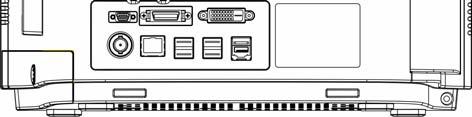

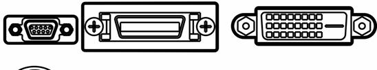

33 2.2.3 Rear View Radiator
34 1. AC Power Input 2. USB Connectors They connect such devices as the USB mice, USB keyboard, etc. 3. Nurse Call Connector It connects the patient monitor to the hospital s nurse call system. Alarms indications are alerted to nurses through the nurse call system, if configured to do so. 4. Micro-D Connector It outputs ECG, IBP and defibrillator synchronization signals simultaneously, among which the ECG signals supports pace pulses to be enhanced. 5. Network Connector It is a standard RJ45 connector that connects the patient monitor to the CMS. 6. CIS Connector It connects the patient monitor to the hospital s clinical information system (CIS) through an external CIS box. The CIS feature is available in China only. 7. Digital Video Interface (DVI) It connects a secondary display, which extends the display capability of your monitor. The contents displayed on the secondary display screen accords with those displayed on the monitor screen. 8. SMR Connector It connects the satellite module rack (SMR). 9. Equipotential Grounding Terminal When the patient monitor and other devices are to be used together, their equipotential grounding terminals should be connected together, eliminating the potential difference between them. 2-6

35 2.3 Satellite Module Rack The Satellite Module Rack (SMR) provides 8 slots for mounting measurement modules. The number of modules mounted in the SMR depends, as different modules may need different slots. Contact Indicator Handle Slot SMR connector As shown in the figure above, there is an indicator telling the status of the SMR: On: when the SMR works normally. Off: when the SMR disconnects from the patient monitor, there is a problem with the power, or the patient monitor shuts down. The SMR can be connected to the patient monitor through their SMR connectors via a SMR cable. NOTE To ensure a good contact, clean the contacts regularly, as dust and dirt may collect on them. When cleaning the contacts, wipe them with cotton, dampened with alcohol. (using forceps is recommended) 2-7

36 2.4 Modules As shown below, the patient monitor supports the following modules: MPM: Multi-parameter module. It can simultaneously monitor ECG, respiration, SpO 2, temperature, NIBP and IBP. IBP module: Invasive blood pressure module. C.O. module: Cardiac output module. CCO/SvO2 module CCO/SvO2 interface module, used to interface with Edwards Vigilance II monitor. CO 2 module: Carbon dioxide module (including sidestream, microstream and mainstream). AG module: Anaesthesia gas module. The functions of the O 2 and BIS modules can be incorporated into it. ICG module: Impedance cardiography module. BIS module: Bispectral index module. RM module: Respiration mechanics module. Under the maximum configuration, the patient monitor has one two-slot module rack, one three-slot module rack and one satellite module rack. The number of modules mounted in the patient monitor depends, as different modules may need different slots Plug-In Modules You can plug and unplug modules during patient monitoring. To plug a module, insert the module until the lever on the module clicks into place and then push the lock key at the bottom in position to lock the module. To remove a module, release the lock key, press the lever upwards and pull the module out. Make sure that the indicator on the module lights on after the module is plugged in. Otherwise, re-plug the module until the indicator lights on. 2-8

37 2.4.2 Multi-Parameter Module The multi-parameter module (MPM) incorporates multiple measurement modules. As shown below, the module name is located at the upper left corner, all hardkeys on the upper part, and all measurement connectors on the lower part. Other measurement modules look similar to the MPM Module name 2. Setup key: press to enter the [MPM Setup] menu. 3. Zero key: press to enter the [Zero IBP] menu. 4. NIBP start/stop key: press to start or stop NIBP measurements. 5. Indicator On: when the patient monitor works correctly. Flash: when the module is being initialized. Off: when the module is either unconnected or broken. 6. Measurement connectors 2-9

38 2.5 Display Screen This patient monitor adopts a high-resolution TFT LCD to display patient parameters and waveforms. A typical display screen is shown below Patient Information Area This area shows the patient information such as department, bed number, patient name, patient category and paced status. : indicates that no patient is admitted or the patient information is incomplete. : indicates that the patient has a pacer. If no patient is admitted, selecting this area will enter the [Patient Setup] menu. If a patient has been admitted, selecting this area will enter the [Patient Demographics] menu. 2. Alarm Symbols indicates alarms are paused. indicates alarm sounds are paused. 2-10
39 indicates alarm sounds are turned off. 3. Technical Alarm Area This area shows technical alarm messages and prompt messages. When multiple messages come, they will be displayed circularly. Select this area and the technical alarm list will be displayed. 4. Physiological Alarm Area This area shows physiological alarm messages. When multiple alarms occur, they will be displayed circularly. Select this area and the physiological alarm list will be displayed. 5. Waveform Area This area shows measurement waveforms. The waveform name is displayed at the left upper corner of the waveform. Select this area and the corresponding measurement setup menu will be displayed. 6. Parameter Area A This area shows measurement parameters. Each monitored parameter has a parameter window and the parameter name is displayed at the upper left corner. The corresponding waveform of each parameter is displayed in the same row in the waveform area. Select this area and the corresponding measurement setup menu will be displayed. 7. Parameter Area B For the parameters displayed in this area, their corresponding waveform are not displayed. 8. Prompt Message Area This area shows the prompt messages, network status icons, battery status icons, date and time, etc. For details about battery status symbols, refer to the chapter 27 Batteries. indicates patient monitor is connected to a wire network successfully. indicates the patient monitor has failed to connect a wire network. indicates the wireless function is working. indicates the wireless function is not working. indicates a CF storage card is inserted. indicates a secondary display or remote display is connected. [Screen Setup] button 2-11
40 9. QuickKeys Area This area contains QuickKeys that give you fast access to functions. 2.6 QuickKeys A QuickKey is a configurable graphical key, located at the bottom of the main screen. They give you fast access to functions. Their availability and the order in which they appear on your screen, depend on how your patient monitor is configured. By default, the following QuickKeys are displayed on the screen: Scroll left to display more QuickKeys. Scroll right to display more QuickKeys. Enter the main menu Enter standby mode Change alarm settings Review the patient s data Enter the NIBP measurement menu Stop all NIBP measurement Zero IBP Change screen Enter the patient setup menu Trigger a manual event Start the realtime print Print Setup Have a split-screen view of minitrends Enter the volume setup menu 2-12
41 Default configurations Have the CIS view You can also select your desired QuickKeys to display on the screen. 1. Select [Main Menu][Maintenance >>][User Maintenance >>]enter the required password[select QuickKeys >>]. 2. In the [Select QuickKeys] menu, select your desired QuickKeys and the order of them. Up to two pages of QuickKeys can be selected. 3. Select [Ok]. Besides the default QuickKeys listed above, there are still more QuickKeys: Start cardiac output procedure (not available in USA) View respiratory loops Perform calculations Have a split-screen view of another patient s conditions Have a split-screen view of oxycrg trends Enter the interpretation of resting 12-lead ECG screen (not available in USA) Enter the full-screen 7-lead ECG screen Enter the [Parameters] menu Start NIBP STAT measurement Enter the PAWP measurement screen Enter the CPB mode 2-13
42 FOR YOUR NOTES 2-14
43 3 Basic Operations 3.1 Installation WARNING The equipment shall be installed by personnel authorized by us. The software copyright of the equipment is solely owned by us. No organization or individual shall resort to juggling, copying, or exchanging it or to any other infringement on it in any form or by any means without due permission. Devices connected to the equipment must meet the requirements of the applicable IEC standards (e.g. IEC safety standards for information technology equipment and IEC safety standards for medical electrical equipment). The system configuration must meet the requirements of the IEC medical electrical systems standard. Any personnel who connect devices to the equipment s signal input/output port is responsible for providing evidence that the safety certification of the devices has been performed in accordance to the IEC If you have any question, please contact us. If it is not evident from the equipment specifications whether a particular combination with other devices is hazardous, for example, due to summation of leakage currents, please consult the manufacturers or else an expert in the field, to ensure the necessary safety of patients and all devices concerned will not be impaired by the proposed combination. 3-1
44 3.1.1 Unpacking and Checking Before unpacking, examine the packing case carefully for signs of damage. If any damage is detected, contact the carrier or us. If the packing case is intact, open the package and remove the equipment and accessories carefully. Check all materials against the packing list and check for any mechanical damage. Contact us in case of any problem. NOTE Save the packing case and packaging material as they can be used if the equipment must be reshipped. WARNING When disposing of the packaging material, be sure to observe the applicable waste control regulations and keep it out of children s reach. The equipment might be contaminated during storage and transport. Before use, please verify whether the packages are intact, especially the packages of single use accessories. In case of any damage, do not apply it to patients. 3-2
45 3.1.2 Environmental Requirements The operating environment of the equipment must meet the requirements specified in this manual. The environment where the equipment is used shall be reasonably free from noises, vibration, dust, corrosive, flammable and explosive substances. If the equipment is installed in a cabinet, sufficient space in front and behind shall be left for convenient operation, maintenance and repair. Moreover, to maintain good ventilation, the equipment shall be at least 2 inches (5cm) away from around the cabinet. When the equipment is moved from one place to another, condensation may occur as a result of temperature or humidity difference. In this case, never start the system before the condensation disappears. WARNING Make sure that the operating environment of the equipment meets the specific requirements. Otherwise unexpected consequences, e.g. damage to the equipment, could result. 3-3
46 3.2 Getting Started Turning Power On Once the patient monitor is installed, you can get ready for monitoring: 1. Before you start to make measurements, check the patient monitor, SMR and plug-in modules for any mechanical damage and make sure that all external cables, plug-ins and accessories are properly connected. 2. Plug the power cord into the AC power source. If you run the patient monitor on battery power, ensure that the battery is sufficiently charged. 3. Press the power on/off switch on the monitor s front. The start-up screens are displayed, and the technical alarm lamp and alarm lamp are lit in blue and yellow respectively. Then, the alarm lamp turns into red, and turns off together with the technical alarm lamp after the system gives a beep. 4. The monitor enters the main screen. WARNING Do not use the patient monitor for any monitoring procedure on a patient if you suspect it is not working properly, or if it is mechanically damaged. Contact your service personnel or us Starting Monitoring 1. Decide which measurements you want to make. 2. Connect the required modules, patient cables and sensors. 3. Check that the patient cables and sensors are correctly connected. 4. Check that the patient settings such as [Patient Cat.], [Paced], etc, are appropriate for your patient. 5. Refer to the appropriate measurement section for details of how to perform the measurements you require. 3-4
47 3.3 Disconnecting from Power To disconnect the patient monitor from the AC power source, follow this procedure: 1. Confirm that the patient monitoring is finished. 2. Disconnect the patient cables and sensors from the patient monitor. 3. Make sure to save or clear the patient monitoring data as required. 4. Press and hold the power on/off switch for above 2 seconds. The patient monitor shuts down and you can unplug the power cable. CAUTION Although not recommended, you can press and hold the power on/off switch for 10 seconds to forcibly shut down the monitor when it could not be shut down normally or under some special situations. This may cause loss of data of the patient monitor. 3.4 Using a mouse You can use the USB mouse supplied with the equipment as a monitor input device. The USB mouse can be plugged and unplugged with the monitor on. When you are using a mouse: By default, the left mouse-button is the primary button and the right one the secondary button. Clicking the primary button equals to pressing the knob or selecting the touchscreen. The secondary button is disabled. You can also define the right mouse-button as the primary button by following this procedure: 1. Select [Main Menu][Maintenance >>][User Maintenance >>]enter the required password. 2. Select [Others >>] to enter the [Others] menu. 3. Select [Primary Button] and then select [Right] from the popup list. 3-5
48 3.5 Using Keys The monitor has three types of keys: Softkey: A softkey is a graphic key on the screen, giving you fast access to certain menus or functions. The monitor has three types of softkeys: Waveform keys: Each waveform area can be seen as a softkey. You can enter a waveform setup menu by selecting its corresponding waveform area. Parameter keys: Each parameter area can be seen as a softkey. You can enter a parameter setup menu by selecting its corresponding parameter area. QuickKeys: QuickKeys are configurable graphical keys, located at the bottom of the main screen. For details, refer to the section QuickKeys. Hardkeys: A hardkey is a physical key on a monitoring device, such as the main menu hardkey on the monitor s front. Pop-Up Keys: Pop-up keys are task-related keys that appear automatically on the monitor screen when required. For example, the confirm pop-up key appears only when you need to confirm a change. 3.6 Using Keyboards The on-screen keyboard enables you to enter information. Use the [Back] key to delete the previously entered character. Use the [Caps] to toggle between uppercase and lowercase letters. Select [Enter] to confirm what you have entered and close the on-screen keyboard. 3.7 Using the Touchscreen Select screen items by pressing them directly on the patient monitor s screen. You can enable or disable touchscreen operation by pressing and holding the [Main Menu] QuickKey for 3 seconds. A padlock symbol is displayed if touchscreen operation is disabled. 3-6
49 3.8 Setting the Screen You can enter the [Screen Setup] window as shown below by selecting the [Screen Setup] button in the prompt message area. In this window, you can allocate the positions of the parameters and waveforms. The parameters or waveforms whose positions are not allocated will not be displayed. Area A Area C Area B The ECG parameter and the first ECG waveform always display in the first row. The configurable areas can be classified as Area A, Area B, and Area C. In Area A, you can choose to display the parameters (having waveforms) and their waveforms. Each parameter and the associated waveform are displayed in the same row. In Area B, you can choose to display the parameters and their waveforms. When there is no parameter displayed in area C, both the parameters and their waveforms will be displayed in area B. Otherwise, only the parameters will be displayed. In Area C, you can choose to display all the parameters whose associated waveforms will not be displayed. The screen can automatically adjust to ensure the best view based on your screen setup. 3-7

50 If no corresponding parameter or waveform is displayed after the module is inserted, you should perform the following inspections: Check the connection between the module and lead, cable, sensor, or external device. Check whether there are the [The display setup for XX is disabled] message and the flashing [Screen Setup] button in the prompt message area. If yes, select this button to enter the [Screen Setup] window for the desired display configuration. WARNING The parameters whose positions are not allocated in the [Screen Setup] window will not be displayed. However, the monitor can still give alarms of these parameters. 3.9 Using the Main Menu To enter the main menu, select the on-screen QuickKey or the hardkey on the monitor s front. Most of monitor operations and settings can be performed through the main menu Other menus are similar to the main menu and contain the following parts: 1. Heading: gives a sum-up for the current menu. 3-8

51 2. Main body: displays options, buttons, prompt messages, etc. The menu button with >> enlarges a secondary window to reveal more options or information. 3. Online help area: displays help information for the highlighted menu item. 4. : select to exit the current menu Setting Parameters Accessing the Parameters Menu Select [Parameters >>] from the main menu or select the [Parameters] QuickKey at the bottom of the screen to enter the [Parameters] menu where you can get the access of each parameter s setup menu. You can further select [Module Status >>] to enter the menu as shown below. Your display may be configured to look slightly different depending on the modules mounted. This menu displays the measurement modules mounted in the two-slot module rack, three-slot module rack and satellite module rack from top to bottom. Beside each measurement connector is the measurement label. The color in which a measurement connector appears matches the status as follows: (colored) indicates that the module is turned on. (grey) indicates that the module is turned off. indicates a module name conflict. indicates a module error. 3-9
52 Removing a Module Conflict Besides three independent IBP modules and the IBP module on the MPM, the patient monitor supports only one more measurement module simultaneously. Otherwise, the message of module conflict will de prompted. For example, if a CO 2 module (module A) is already loaded and then another CO 2 module (module B) is inserted, your patient monitor will then display module conflict. To use module A, just pull out module B. To use module B, pull both modules A and B out and then re-insert module B Removing a Label Conflict Every label is unique and is assigned only once. The measurement label is stored inside the module. The system will prompt module name conflict when two measurement modules with the same name are used. For example, an IBP module (module A) is already loaded and the Art label is used for module A. Then another IBP module (module B) is inserted and the Art label is also used for module B. In this case, your patient monitor will prompt the message of label conflict and display the [Label] menu. To use module A for Art measurement, just modify the label of module B on this channel in the [Label] menu. If the [Label] menu already exits inadvertently, you need to plug out and then plug in module B. To use module B for Art measurement, first exit the [Label] menu. Then select the Art parameter area on the screen and modify the label of module A on this channel in the popup menu. Finally, plug out and then plug in module B. 3-10
53 3.11 Using a CF Storage Card A CF storage card is used to prevent data loss in case of a sudden power failure. The patient data such as trend data, waveform data, etc., will be automatically saved into the CF storage card during patient monitoring. In case of a sudden power failure, the patient data can be retrieved from the CF storage card after the patient monitor restarts. Switching the patient monitor off before inserting or removing a CF card is a must. To insert a CF storage card, open the compartment and then insert the card until the button flips out. To remove the CF storage card, press the button until the CF storage card flips out. To browse the data saved in the CF storage card, follow this procedure: 1. Select [Main Menu] [Patient Data >>] [History Data >>]. 2. Select a patient whose data you want to view from the [Patient Data List] and then select [Review]. 3. Select [Data Review]. As reviewing the history patient s data is just like reviewing the current patient s data, you can refer to the chapter 22 Review for details. If CF card problem occurs, you can refer to the following table for solutions. Symptoms Possible Cause Corrective Action CF card malfunctions Wrong CF card or small memory space CF card full; data error; CF card error CF card failure Cable defective or poorly connected CF card board failure Mother board failure Use only SanDisk-manufactured CF storage cards. Those with 1GB memory space are recommended. Format CF card on PC. Replace the CF card. 1. Check that the cable between CF card board and mother board is correctly connected. 2. Check that connecting cables and connectors not damaged. Replace the CF card board. Replace the mother board. 3-11
54 NOTE Data may be unable to be saved into the CF storage card when the patient monitor is just turned on. If no CF stroage card is used, all the data you have saved will get lost in case of monitor shut-down or sudden power interrupt. CAUTION To avoid electrostatics, do not come into contact with the CF storage card when the patient monitor is on. Do not insert or remove the CF storage card when the patient monitor is on. Otherwise it may cause damage to the CF storage card and the patient monitor. Use only the CF storage card specified in this manual Changing General Settings This chapter covers only general settings such as language, brightness, date and time, etc. Measurement settings and other settings can be referred to in respective sections Setting up a Monitor In situations where you install a patient monitor or change the patient monitor s application site, you need to setup the patient monitor as follows: 1. Select [Main Menu] [Maintenance >>] [User Maintenance >>] enter the required password. 2. In the [User Maintenance] menu, select, in turn, [Monitor Name], [Department] and [Bed No.], and then change their settings Changing Language 1. Select [Main Menu] [Maintenance >>] [User Maintenance >>] enter the required password. 2. In the [User Maintenance] menu, select [Language] and then select the desired language. 3. Restart the patient monitor. 3-12
55 Adjusting the Screen Brightness 1. Select the [Main Menu] [Screen Setup >>] [Brightness]. 2. Select the appropriate setting for the screen brightness. 10 is the brightest, and 1 is the least bright. If the patient monitor operates on battery power, you can set a less bright screen to prolong the operating time of the battery. When the patient monitor enters standby mode, the screen will change to the least brightness automatically Showing/Hiding the Help The patient monitor provides online help information. The user can display or hide the help as required. 1. Select [Main Menu] [Screen Setup >>]. 2. Select [Help] and toggle between [On] and [Off] Setting the Date and Time 1. Select [Main Menu] [Maintenance >>] [System Time >>]. 2. Set the date and time. 3. Select [Date Format] and toggle between [yyyy-mm-dd], [mm-dd-yyyy] and [dd-mm-yyyy]. 4. Select [Time Format] and toggle between [24h] and [12h]. If your patient monitor is connected to a central monitoring system (CMS), the date and time are automatically taken from that CMS. In that case, you cannot change the date and time settings on your patient monitor. CAUTION Changing date and time will affect the storage of trends and events and may cause data missing. 3-13
56 Adjusting Volume Alarm Volume 1. Select the [Volume Setup] QuickKey, or [Main Menu][Alarm Setup >>][Others]. 2. Select [Alm Volume] and then select the appropriate volume: X-10, in which X is the minimum volume, depending on the set minimum alarm volume (refer to the chapter Alarm), and 10 the maximum volume. Key Volume 1. Select the [Volume Setup] QuickKey, or [Main Menu][Screen Setup >>]. 2. Select [Key Volume] and then select the appropriate volume. 0 means off, and 10 the maximum volume. QRS Volume The QRS tone is derived from either the HR or PR, depending on which is currently selected as the alarm source in [ECG Setup] or [SpO2 Setup]. When monitoring SpO 2, there is a variable pitch tone which changes as the patient s saturation level changes. The pitch of the tone rises as the saturation level increases and falls as the saturation level decreases. The volume of this tone is user adjustable. 1. Select the [Volume Setup] QuickKey, or the ECG parameter window[others >>], or the SpO 2 parameter window. 2. Select [QRS Volume] or [Beat Vol] and then select the appropriate volume. 0 means off, and 10 the maximum volume. 3-14
57 3.13 Managing Configurations Restoring the Latest Configuration Automatically During operation, you may make changes to some settings. However, these changes may not be saved as user configuration. To prevent the changes from losing in case of a sudden power failure, the patient monitor stores the configuration in real time. The saved configuration is the latest configuration. The monitor restore the latest configuration if restarts within 60 seconds after the power failure. And it will restore the default configuration rather than the latest configuration if restarts 120 seconds later after the power failure. The monitor may load either the latest configuration or the default configuration if restarts from seconds after the power failure Setting Default Configuration at Startup When the patient monitor restarts after quitting over 120 seconds, it will load the pre-set default configuration to restore the system configuration. The default configuration can be either the latest configuration, or a factory or user configuration. To set default configuration at startup: 1. Select [Main Menu][Maintenance >>][User Maintenance >>]enter the required password[manage Configuration >>]. 2. Select [Select Default Config. >>]. 3. In the [Select Default Config.] menu, toggle between [Load Last Config.] and [Load Specified Config.]. When you select [Load Specified Config.], the configuration (adult, pediatric or neonate) to be restored is subject to the patient category. This configuration can be either factory configuration or saved user configuration. Take adult as an example, select [Default Adu Config.] and toggle between [Factory Default Adu Config.] or user configuration(s). NOTE To know what configuration is restored when the patient monitor starts, enter the main screen to check the prompt information at the lower part of the screen (displayed for about 10 seconds). 3-15
58 Saving as User Configuration You can change monitor settings as required and then save the changed settings into a user configuration. This patient monitor can save multiple user configurations, and you can name the saved user configurations. 1. Change monitor setting as required and make sure that the changes are suitable for your patient. 2. Select [Main Menu][Maintenance>>][User Maintenance >>]enter the required password[manage Configuration >>]. 3. Select [Save as User Default Config. >>]. 4. Enter a name and select [Save]. If the entered name already exists, a message box will appear. Proceed by following the message. The configuration name saved in the patient monitor is in the form of entered name+patient category+config. e.g., if you enter the name ICU1 and the current patient is an adult, the configuration name will be ICU1 Adult Config Deleting a User Default Configuration You can delete an already saved user configuration. 1. Select [Main Menu][Maintenance>>][User Maintenance >>]enter the required password[manage Configuration >>]. 2. Select [Delete User Default Config. >>]. 3. Select the configuration to be deleted. Select [Delete] and then select [Yes] from the popup menu. 3-16
59 Restoring Default Configuration Manually You may make changes to some settings in some occasions. However, these changes may not be appropriate or correct, especially when a new patient is admitted. Therefore, in actual applications, you should restore the default configuration as required so as to ensure that the applied configuration is suitable for your patient. To restore a certain default configuration: 1. Select [Main Menu][Defaults >>]. 2. Select a factory or user configuration. 3. Select [Yes]. 3-17
60 FOR YOUR NOTES 3-18
61 4 Managing Patients 4.1 Admitting a Patient The patient monitor displays physiological data and stores them in the trends as soon as a patient is connected. This allows you to monitor a patient that is not admitted yet. However, it is recommended that you fully admit a patient so that you can clearly identify your patient, on recordings, reports and networking devices. To admit a patient: 1. Select the [Patient Setup] QuickKey, or [Main Menu][Patient Setup >>]. 2. Select [Discharge Patient] to clear any previous patient data. If you do not erase data from the previous patient, the new patient s data will be saved into the data of the previous patient. The monitor makes no distinction between the old and the new patient data. 3. If [Discharge Patient] button appears dimmed, directly select [Admit Patient] and then select: [Yes] to apply the data saved in the patient monitor to the new patient, or [No] to clear the data saved in the patient monitor. 4. In the [Patient Demographics] menu, enter the demographic details, of which: [Patient Cat.] determines the way your patient monitor processes and calculates some measurements, and what safety and alarm limits are applied for your patient. [Paced] determines whether to show pace pulse marks on the ECG waveform. When the [Paced] is set to [No], pace pulse marks are not shown in the ECG waveform. 5. Select [Ok]. 4-1
62 WARNING [Patient Cat.] and [Paced] will always contain a value, regardless of whether the patient is fully admitted or not. If you do not specify settings for these fields, the patient monitor uses the default settings from the current configuration, which might not be correct for your patient. For paced patients, you must set [Paced] to [Yes]. If it is incorrectly set to [No], the patient monitor could mistake a pace pulse for a QRS and fail to alarm when the ECG signal is too weak. For non-paced patients, you must set [Paced] to [No]. If it is incorrectly set to [Yes], the patient monitor may be unable to detect premature ventricular beats (including PVCs) and perform ST segment analysis. 4.2 Quick Admitting a Patient Use [Quick Admit] only if you do not have the time or information to fully admit a patient. Complete the rest of the patient demographic details later. Otherwise, the symbol will always be displayed in the patient information area. 1. Select the [Patient Setup] QuickKey, or [Main Menu][Patient Setup >>]. 2. Select [Quick Admit]. If a patient has been admitted at present, select [OK]to discharge the current patient. If.no patient is admitted, you can choose either: [Yes] to apply the data in your patient monitor to the new patient, or [No] to clear any previous patient data. 3. Enter the patient category and paced status for the new patient, and then select [Ok]. 4-2
63 4.3 Editing Patient Information To edit the patient information after a patient has been admitted, or when the patient information is incomplete, or when you want to change the patient information: 1. Select the [Patient Setup] QuickKey, or [Main Menu][Patient Setup >>]. 2. Select [Patient Demographics] and then make the required changes. 3. Select [Ok]. 4.4 Discharging a Patient To discharge a patient: 1. Select the [Patient Setup] QuickKey, or [Main Menu][Patient Setup >>]. 2. Select [Discharge Patient]. In the popup dialog box, you can either: Select [Ok]. The patient monitor enters the standby mode after discharging the current patient, or Select [Cancel] to exit without discharging the patient. NOTE Discharging a patient clears all history data in the monitor. 4.5 Transferring a Patient You can transfer a patient with an MPM to a new location without re-entering the patient demographic information or changing the settings. Transferring of patient data enables you to understand the patient s history condition. Familiarizing yourself with the data respectively stored in the patient monitor and MPM helps you understand the effects incurred by transferring patients with an MPM. 4-3
64 Contents stored In the patient monitor In the MPM Data Patient demographics Yes Yes (Name, Bed No., Gender, etc.) Trend data Yes Yes Calculation data Yes No (Dose calculations, oxygenation calculations, etc.) Event data Yes No (Marked events, alarm events, etc.) Settings Monitor settings Yes No (Alarm pause, alarm volume, etc.) Parameter settings Yes Yes (Alarm limits, measurement module on/off, etc.) Before transferring a patient with an MPM, set on the desired monitor as follows: 1. Select [Main Menu] [Maintenance] [User Maintenance >>] enter the required password. 2. Select [Others >>]. 3. Set [Transfer MPM Data] to [On]. 4. Set [Apply MPM Settings] to [On]. If your patient monitor does not have this option, the system applies MPM settings by default. Then, follow this procedure to transfer the patient: 1. Disconnect the MPM from the original monitor. 2. Connect the MPM to the monitor. 3. If there is a mismatch between the MPM and monitor, the system will automatically display the [Select Patient] menu, from which you can choose the data set you want to continue using for this patient, either: [Continue Monitor]:continue with the patient data and settings in the monitor, deleting all patient data and setting in the MPM and copying all data in the monitor to the MPM. [Continue MPM]:continue with the patient data and settings in the MPM. Discharge the patient in the monitor. The monitor then automatically admits the patient and copies all data from the MPM. 4-4
65 [New Patient]: select this button if none of the information is correct. This deletes all data in the monitor and MPM and lets you admit a new patient on the monitor. In this case, you need to re-enter the patient demographics. The monitor will restore the settings according to the patient category. [Same Patient]:select this button if the patient demographics are different, but it is the same patient. This merges the patient s trend data in the monitor and MPM and copies the settings in the MPM to the monitor as well. 4. Select [Yes]. Operations Continue Monitor Continue MPM New Patient Same Patient Examples of applications 1. Replace the MPM during patient monitoring. 2. After the patient is admitted, connect the MPM. A patient is monitored using an MPM. You need to move the patient to a new location, e.g. from a ward (original monitor) to the operating room (destination monitor) Connect the MPM before admitting a new patient. However, the monitor and/or MPM store the previous patient s data and settings. A patient is admitted by a monitor, to which an MPM used in another monitor for monitoring this patient is connected. WARNING After a patient is successfully transferred, check if the patient settings (especially patient category, paced status and alarm limits settings, etc) on the monitor are appropriate for this patient. Only when you open MPM transfer function and select [Continue MPM], the IBP labels can be transferred along with the MPM module. 4-5
66 4.6 Connecting to Panorama TM Central Station If your patient monitor is connected to a Panorama Central Station: All patient information, measurement data and settings on the patient monitor can be transmitted to the Panorama Central Station. All patient information, measurement data and settings can be displayed simultaneously on the patient monitor and Panorama. For some functions such as editing patient information, admitting a patient, discharging a patient, etc., bi-directional control can be achieved between your patient monitor and Panorama. The patient monitor is also capable of bi-directional transmission of patient alarm settings with a Panorama. For details, refer to the Panorama Operating Instructions Manual. 4-6
67 5 User Screens 5.1 Tailoring Your Screens You can tailor your patient monitor s screens by setting: Waveform sweep mode Wave line size The color in which each measurement s numerics and waveform are displayed The parameter to be monitored. Changing some settings may be hazardous. Therefore, those setting are password-protected and can be modified by authorized personnel only. Once change is made, those who use the patient monitor should be notified Setting the Waveform Sweep Mode 1. Select [Main Menu][Screen Setup >>]. 2. Select [Sweep Mode] and toggle between [Refresh] and [Scroll]. [Refresh]: The waveforms keep stationary, being refreshed from left to right by a moving erase bar. [Scroll]: The waveforms move from the right to the left with time passing by Changing the Wave Line Size 1. Select [Main Menu][Maintenance >>][User Maintenance >>]enter the required password. 2. Select [Others >>]. 3. Select [Wave Line] and toggle between [Thick], [Mediate] and [Thin] Changing Measurement Colors 1. Select [Main Menu][Screen Setup >>][Measurement Color Setup >>]. 2. Select the color box next to your desired measurement and then select a color from the popup menu. 5-1
68 5.1.4 Changing Screen Layout Select the [Screens] QuickKey, or [Main Menu][Screen Setup >>][Screen Layout >>] to enter the [Screens] menu. You can choose the desired screen type in the [Choose Screen] window. You can select the parameters and waveforms you want to view in the [Screen Setup] window. For details, please refer to the section Setting the Screen. You can select the parameters you want to view on big numerics screen in the [Big Numerics Screen Setup] window. 5-2

69 5.2 Viewing Minitrends Having a Split-Screen View of Minitrends You can split the normal screen so that one part of the screen, on the left hand side, continuously shows graphic minitrends beside waveforms as shown in the figure below. To have a split-screen view of minitrends, you can: Select [Minitrends] QuickKey, or Select [Screens] QuickKey[Minitrends Screen], or Select [Main Menu][Screen Setup >>][Screen Layout >>][Minitrends Screen]. Minitrend View The split-screen view provides minitrends for multiple parameters. In each field, the label, scale and time are respectively displayed at the top, left, and bottom as shown below. 5-3
70 5.2.2 Setting Minitrends Select the minitrends area. From the pop-up [Minitrend Setup] menu, you can: Select the parameters to be displayed, or Select [Minitrend Length] and then select the appropriate setting. 5.3 Viewing oxycrg To have a split screen view of oxycrg, you can: Select [oxycrg] QuickKey, or Select [Screens] QuickKey[OxyCRG Screen], or. Select [Main Menu][Screen Setup >>][Screen Layout >>][OxyCRG Screen] The split-screen view covers the lower part of the waveform area and shows HR trend, SpO 2 trend and RR trend (or Resp wave). At the bottom, there are controls: 1. Trend length list box In the trend length list box, you can select [1 min], [2 min], [4 min], or [8 min]. 2. Resp Wave (or RR Trend) list box From this list box, you can select either [Resp Wave] or [RR Trend] for display. 3. Record Through this button, you can print out the currently displayed oxycrg trends by the recorder. 5-4
71 5.4 Viewing Other Patients Care Group If your patient monitor is connected to a central monitoring system, you can select up to 10 patient monitors (including telemetry connected to the same central monitoring system) into a Care Group. This lets you: View information on the monitor screen from another bed in the same Care Group. Be notified of physiological and technical alarm conditions at the other beds in the same Care Group. To have a Care Group: 1. Open the [View Other Patient] window by: Selecting [Others] QuickKey, or Selecting [Screens] QuickKey [View Others Screen], or Selecting [Main Menu] [Screen Setup >>] [Screen Layout >>] [View Others Screen]. 2. Select [Setup] in the [View Other Patient] window. 3. Select the desired patient monitors from the [Connected Monitor List], and then select the button. The selected patient monitors constitute a Care Group. NOTES View other patient function is not available between wireless monitors, nor for wireless monitors to view wired monitors. View other patient function is available between wired monitors, or for wired monitors to view wireless monitors. 5-5
72 5.4.2 Viewing the Care Group Overview Bar The Care Group overview bar locates at the bottom of the [View Other Patient] window. In the overview bar, the department and bed label for any Care Group beds are displayed. For telemetry, # is displayed before the department label. The color in which a Care Group bed appears matches its status: Red: indicates the bed is giving high-level physiological alarms or the telemetry is giving alarm, such as nurse call or event. Yellow: indicates the bed is giving medium- or low-level physiological alarms, or medium-level technical alarms. Blue: indicates the bed is giving low-level technical alarms. Grey: indicates the bed fails to be networked or stays in the standby mode. You can view a Care Group bed s alarms by selecting it from the care group, and as well you can select the [View This Patient] button to view this bed in the [View Other Patient] window. For more details about Care Group alarms, refer to the Alarms chapter. 5-6
73 5.4.3 Understanding the View Other Patient Window When you first open the [View Other Patient] window, the patient monitor automatically selects a monitor from the network to display in the [View Other Patient] window The [View Other Patient] window covers the lower part of the waveform area and consists of: 1. Information Area: shows the patient information (including department, bed number, patient name, etc.), network status symbol. 2. View Area: shows physiological waveforms and parameters. You can switch a waveform area to a parameter area by selecting your desired waveform area and then selecting [Switch to Parameter Area], or switch a parameter area to a waveform area by selecting your desired parameter area and then selecting [Switch to Waveform Area]. 3. Care Group Overview Bar. 4. Message Area: shows physiological, technical and prompt messages from the currently viewed patient monitor. It also shows the alarm given by the telemetry such as nurse call or event. By selecting this area, you can enter the [Alarm Information List] to view all physiological, technical and prompt messages coming from the currently viewed patient. Additionally, you can change a waveform or parameter for viewing To change a waveform for viewing, select the waveform segment where you want a new waveform to appear and then select the waveform you want from the popup menu. To change a parameter for viewing, select the parameter window where you want a new parameter to appear and then select the parameter you want from the popup menu. 5-7
![WARNING The data presented in the [View Other Patient] window have delay. Do not rely on this window for realtime data. 5.5 Understanding the Big Numerics Screen To enter the big numerics screen: 1.](/docs-images/74/70143413/images/74-0.jpg "Select the [Screens] QuickKey, or [Main Menu][Screen Setup >>][Screen Layout >>]. 2. Select [Big Numerics].")
74 WARNING The data presented in the [View Other Patient] window have delay. Do not rely on this window for realtime data. 5.5 Understanding the Big Numerics Screen To enter the big numerics screen: 1. Select the [Screens] QuickKey, or [Main Menu][Screen Setup >>][Screen Layout >>]. 2. Select [Big Numerics]. You can select your desired parameters to display in this screen: select the [Screens] QuickKey[Big Numerics Screen Setup] and then select the parameters you want. For parameters having a waveform, the waveform will also be displayed. 5-8
75 6 Alarms Alarms, triggered by a vital sign that appears abnormal or by technical problems of the patient monitor, are indicated to the user by visual and audible alarm indications. WARNING A potential hazard can exist if different alarm presets are used for the same or similar equipment in any single area, e.g. an intensive care unit or cardiac operating room. If your patient monitor is connected to a CMS, remote suspension, inhibition, silence and reset of monitor alarms via the CMS may cause a potential hazard. 6.1 Alarm Categories By nature, the patient monitor s alarms can be classified into three categories: physiological alarms, technical alarms and prompt messages. 1. Physiological alarms Physiological alarms, also called patient status alarms, are triggered by a monitored parameter value that violates set alarm limits or an abnormal patient condition. Physiological alarm messages are displayed in the physiological alarm area. 2. Technical alarms Technical alarms, also called system status alarms, are triggered by a device malfunction or a patient data distortion due to improper operation or mechanical problems. Technical alarm messages are displayed in the technical alarm area. 3. Prompt messages As a matter of fact, prompt messages are not alarm messages. Apart from the physiological and technical alarm messages, the patient monitor will show some messages telling the system status. Messages of this kind are included into the prompt message category and usually displayed in the prompt information area. But for some measurements, their related prompt messages are displayed in their respective parameter windows. 6-1
76 6.2 Alarm Levels By severity, the patient monitor s alarms can be classified into three categories: high level, medium level and low level.. High level Medium level Low level Physiological alarms Indicate that your patient is in a life threatening situation, such as Asystole, Vfib/Vtac and so forth, and an emergency treatment is demanded. Indicate that your patient s vital signs appear abnormal and an immediate treatment is required. Indicate that you patient s vital signs appear abnormal and an immediate treatment may be required. Technical alarms Indicate a severe device malfunction or an improper operation, which could make it possible that the monitor cannot detect critical patient status and thus threaten the patient s life, such as low battery. Indicate a device malfunction or an improper operation, which may not threaten the patient s life but may compromise the monitoring of vital physiological parameters. Indicate a device malfunction or an improper operation, which may compromise a certain monitoring function but will not threaten the patient s life. 6.3 Alarm Indicators When an alarm occurs, the patient monitor will indicate it to the user through visual or audible alarm indications. Alarm lamp Alarm message Flashing numeric Audible alarm tones Reminder Tones Alarm Lamp If a technical alarm occurs, the technical alarm lamp will turn blue. If a technical alarm or physiological alarm occurs, the alarm lamp will flash. The flashing color and frequency match the alarm level as follows: High level alarms: the lamp quickly flashes red. Medium level alarms: the lamp slowly flashes yellow. Low level physiological alarms: the lamp turns yellow without flashing. Low level technical alarms: the lamp does not light. 6-2
77 6.3.2 Alarm Message When an alarm occurs, an alarm message will appear in the technical or physiological alarm area. For physiological alarms, the asterisk symbols (*) before the alarm message match the alarm level as follows: High level alarms: *** Medium level alarms: ** Low level alarms: * Additionally, the alarm message uses different background color to match the alarm level: High level alarms: red Medium level alarms: yellow Low level physiological alarms: yellow Low level technical alarms: blue You can view the alarm messages by selecting the physiological or technical alarm area Flashing Numeric If an alarm triggered by an alarm limit violation occurs, the numeric of the measurement in alarm will flash every second, and the corresponding alarm limit will also flash at the same frequency indicating the high or low alarm limit is violated Audible Alarm Tones This monitor has three choices of alarm tones and patterns: ISO, Mode 1 and Mode 2. For each pattern, the alarm tones identify the alarm levels as follows: ISO pattern: High level alarms: triple+double+triple+double beep. Medium level alarms: triple beep. Low level alarms: single beep. Mode 1: High level alarms: high-pitched single beep. Medium level alarms: double beep. Low level alarms: low-pitched single beep. 6-3
78 Mode 2: High level alarms: high-pitched triple beep. Medium level alarms: double beep. Low level alarms: low-pitched single beep. NOTE When multiple alarms of different levels occur simultaneously, the patient monitor will select the alarm of the highest level and give visual and audible alarm indications accordingly Reminder Tones When alarm tones are silenced or turned off, the patient monitor will give a single beep in case of an active alarm condition Alarm Status Symbols Apart from the aforementioned alarm indicators, the patient monitor still uses the following symbols telling the alarm status: indicates alarms are paused. indicates alarm sound is silenced. indicates the alarm sound is turned off. indicates individual measurement alarms are turned off. 6-4
79 6.4 Alarm Tone Configuration Setting the Minimum Alarm Volume 1. Select [Main Menu][Maintenance >>][User Maintenance >>]enter the required password. 2. Select [Alarm Setup >>] to enter the [Alarm Setup] menu. 3. Select [Minimum Alarm Volume] and toggle between 0 and 10. The minimum alarm volume refers to the minimum value you can set for the alarm volume, which is not affected by user or factory default configurations. The setting of minimum alarm volume remains unchanged when the patient monitor shuts down and restarts Changing the Alarm Volume 1. Select the [Volume Setup] QuickKey or the [Alarm Setup] QuickKey[Others], or [Main Menu][Alarm Setup >>][Others]. 2. Select the appropriate volume from [Alm Volume]: X-10, in which X is the minimum volume, depending on the set minimum alarm volume, and 10 the maximum volume. When alarm volume is set to 0, the alarm sound is turned off and a screen. The alarm volume returns to 2 automatically when: symbol appears on the The patient monitor is shut down and then restarted. A certain user configuration which saves alarm volume as 0 is restored. The factory default configuration is restored. A switch between alarm statuses is made. 6-5
80 6.4.3 Setting the Interval between Alarm Sounds You cannot change the interval between alarm tones if you choose mode 1 or 2 as your desired alarm tone pattern. For these two patterns, the interval between alarm tones identifies the alarm levels as follows: Mode 1: Interval between high level alarm tones: continuously. Interval between medium level alarm tones: 5 s. Interval between low level alarm tones: 20 s. Mode 2: Interval between high level alarm tones: 1 s. Interval between medium level alarm tones: 5 s. Interval between low level alarm tones: 20 s. If you choose the ISO pattern, you can change the interval between alarm tones. To change the interval between alarm tones: 1. Select [Main Menu][Maintenance >>][User Maintenance >>]enter the required password. 2. Select [Alarm Setup >>] to enter the [Alarm Setup] menu. 3. Select [High Alarm Interval (s)], [Med Alarm Interval (s)] and [Low Alarm Interval (s)] in turn and then select the appropriate settings. WARNING When the alarm sound is switched off, the patient monitor will give no audible alarm tones even if a new alarm occurs. Therefore the user should be very careful about whether to switch off the alarm sound or not. Do not rely exclusively on the audible alarm system for patient monitoring. Adjustment of alarm volume to a low level may result in a hazard to the patient. Always keep the patient under close surveillance. 6-6
81 6.4.4 Changing the Alarm Tone Pattern To change the alarm tone pattern: 1. Select [Main Menu][Maintenance >>][User Maintenance >>]enter the required password. 2. Select [Alarm Setup >>] to enter the [Alarm Setup] menu. 3. Select [Alarm Sound] and toggle between [ISO], [Mode 1]and [Mode 2]. User or factory default configurations exert no impact on the setup of alarm tone pattern. The alarm tone pattern remains unchanged after the monitor restarts Setting the Reminder Tones 1. Select [Main Menu][Maintenance >>][User Maintenance >>]enter the required password. 2. Select [Alarm Setup >>] to enter the [Alarm Setup] menu. To switch the reminder tones on or off, select [Reminder Tones] and toggle between [On] and [Off]. To set the interval between reminder tones, select [Reminder Interval] and toggle between []1min], [2min] and [3min]. In addition, you can set the volume of alarm reminder tones. To set the volume of alarm reminder tones, select [Main Menu][Alarm Setup >>][Others] or the [Alarm Setup] QuickKey[Others]. Then, select [Reminder Vol] and toggle between [High], [Medium] and [Low]. 6.5 Understanding the Alarm Setup Menu Select the [Alarm Setup] QuickKey or [Main Menu][Alarm Setup >>] to enter the [Alarm Setup], where you can: Set alarm properties for all parameters. Change ST alarm settings. Change arrhythmia alarm settings. Set the threshold for some arrhythmia alarms. Change other settings. 6-7

82 Please refer to the ECG section for how to change ST alarm settings, how to change arrhythmia alarm settings and how to set the threshold for some arrhythmia alarms Setting Alarm Properties for All Parameters In the main menu, select [Alarm Setup >>][Parameters]. You can review and set alarm limits, alarm level and alarm recordings for all parameters. When a measurement alarm occurs, automatic recording of all the measurement numerics and related waveforms is possible when the measurement s high/low alarm limit and [Record] are set on. WARNING Make sure that the alarm limits settings are appropriate for your patient before monitoring. Setting alarm limits to extreme values may cause the alarm system to become ineffective. For example, High oxygen levels may predispose a premature infant to retrolental fibroplasia. If this is a consideration do NOT set the high alarm limit to 100%, which is equivalent to switching the alarm off Adjusting Alarm Limits Automatically The monitor can automatically adjust alarm limits according to the measured vital signs, using the auto limits function. When auto limits are selected, the monitor calculates safe auto limits based on the latest measured values. To get accurate auto alarm limits, you need to collect a set of measured vital signs as a 6-8
83 baseline. Then, in the main menu, select [Alarm Setup >>][Parameters][Auto Limits] [Ok]. The monitor will create new alarm limits based on the measured values. Before applying these automatically created alarm limits, confirm if they are appropriate for your patient in the mass alarm setup menu. If not, you can adjust them manually. These alarm limits will remain unchanged until you select auto limits again or adjust them manually. The monitor calculates the auto limits based on the following rules. Module Low alarm limit Parameter Adult/ Neonate pediatric High alarm limit Adult/ Neonate pediatric Auto alarm limits range HR0.8 or HR-30 or HR1.25 or HR40 or Adult/pediatric ECG HR/PR 40bpm whichever 90bpm whichever is 240bpm 200bpm whichever is whichever is 35 to 240 Neonate55 to is greater greater smaller smaller 225 Resp RR RR0.5 or 6/min whichever is greater RR-10 or 30/min whichever is greater RR1.5 or RR+25 or 30/min 85/min whichever is whichever is smaller smaller Adult/pediatric6 to 55 Neonate10 to 90 Same as the Same as the Same as the Same as the Same as the SpO2 SpO2 default alarm default alarm default alarm default alarm measurement limit limit limit limit range NIBP-S SYS-15 or SYS mmHg 10mmHg whichever is greater SYS mmHg SYS15 or 105mmHg whichever is smaller Adult45 to 270 Pediatric45 to 185 Neonate35 to 115 Dia-15 or Dia15 or Adult25 to 225 NIBP NIBP-D Dia0.68 6mmHg 20mmHg whichever is Dia mmHg 80mmHg whichever is Pediatric25 to 150 greater smaller Neonate20 to 90 NIBP-M Mean0.68 8mmHg Mean-15 or 35mmHg whichever is greater Mean15 or Mean mmHg 35mmHg whichever is smaller Adult30 to 245 Pediatric30 to 180 Neonate25 to 105 Temp T1 T10.5 T10.5 T10.5 T to 49 T2 T20.5 T20.5 T20.5 T to
84 Module Low alarm limit Parameter Adult/ Neonate pediatric High alarm limit Adult/ Neonate pediatric Auto alarm limits range Same as the Same as the Same as the Same as the Same as the TD default alarm default alarm default alarm default alarm measurement limit limit limit limit range IBP ART/ Ao/ IBP-S SYS-15 or SYS mmHg 10mmHg whichever is greater SYS mmHg SYS15 or 105mmHg whichever is smaller Adult45 to 270 Pediatric45 to 185 Neonate35 to 115 UAP/ BAP/ FAP/ IBP-D Dia0.68 6mmHg Dia-15 or 20mmHg whichever is Dia mmHg Dia15 or 80mmHg whichever is Adult25 to 225 Pediatric25 to 150 LV/ greater smaller Neonate20 to 90 P1-P4 (Arterial pressure) IBP-M Mean0.68 8mmHg Mean-15 or 35mmHg whichever is greater Mean15 or Mean mmHg 35mmHg whichever is smaller Adult30 to 245 Pediatric30 to 180 Neonate25 to
85 Module Low alarm limit Parameter Adult/ Neonate pediatric High alarm limit Adult/ Neonate pediatric Auto alarm limits range PA IBP-S SYS0.75 SYS0.75 SYS1.25 SYS1.25 IBP-D Dia0.75 Dia0.75 Dia1.25 Dia1.25 IBP-M Mean0.75 Mean0.75 Mean1.25 Mean to 120mmHg IBP: CVP/ ICP/ LAP/ RAP/ UVP/ P1-P4 (Venous pressure ) IBP-M Mean0.75 Mean0.75 Mean1.25 Mean to 40mmHg 0-32mmHg: 0-32mmHg: 0-32mmHg: 0-32mmHg: remains the remains the remains the remains the same same same same 32-35mmHg: 32-35mmHg: 32-35mmHg: 32-35mmHg: 29mmHg 29mmHg 41mmHg 41mmHg EtCO mmHg: 35-45mmHg: 35-45mmHg: etco2-6mmh etco2+6mmh etco2-6mmhg g g Same as the 35-45mmHg: measurement etco2+6mmhg range 45-48mmHg: 45-48mmHg: mmHg: mmHg:51 CO2 39mmHg mmhg 1mmHg mmhg >48mmHg: >48mmHg: >48mmHg: >48mmHg: remains the remains the remains the remains the same same same same Same as the Same as the Same as the FiCO2 N/A N/A default alarm default alarm measurement limit limit range awrr awrr0.5 or 6/min whichever is greater awrr-10 or 30/min whichever is greater awrr1.5 or awrr+25 or 30/min 85/min whichever is whichever is smaller smaller Adult/pediatric6 to 55 Neonate10 to
86 Module Low alarm limit Parameter Adult/ Neonate pediatric High alarm limit Adult/ Neonate pediatric Auto alarm limits range EtCO2 AG FiCO2 (AG) Same as CO2 module awrr awrr0.5 or 6/min whichever is greater awrr-10 or 30/min whichever is greater awrr1.5 or awrr+25 or 30/min 85/min whichever is whichever is smaller smaller Adult/pediatric6 to 55 Neonate10 to 90 AG FiAA/ EtAA Same as the default alarm limit Same as the default alarm limit Same as the default alarm limit Same as the default alarm limit Same as the measurement range FiO2/ EtCO2 Same as the default alarm limit Same as the default alarm limit Same as the default alarm limit Same as the default alarm limit Same as the measurement range FiN2O/ EtN2O Same as the default alarm limit Same as the default alarm limit Same as the default alarm limit Same as the default alarm limit Same as the measurement range C.O. BT Adult BT1 N/A Adult BT1 N/A Same as the measurement range ICG C.I. TFC N/A RR(RM) awrr0.5 or 6/min whichever is greater N/A awrr1.5 or 30/min N/A whichever is smaller Adult/pediatric6 to 55 Neonate10 to 90 RM PEEP PEEP - 5 N/A PEEP + 5 N/A PIP PIP - 10 N/A PIP + 10 N/A MVe MVe - 2 N/A MVe + 2 N/A Same as the measurement range Same as the measurement range Same as the measurement range BIS BIS N/A 6-12
87 Module Low alarm limit Parameter Adult/ Neonate pediatric High alarm limit Adult/ Neonate pediatric Auto alarm limits range CCO/ CCIEDV/ EDVI CCO SVR/ N/A SVRI SV/SVI RVEF SvO2 SvO2 SvO2-5 N/A SvO2 + 5 N/A ScvO2 ScvO2-5 N/A ScvO2 + 5 N/A Same as the measurement range Same as the measurement range Setting Alarm Delay Time You can set the alarm delay time for over-limit alarms of continuously measured parameters. If the alarm-triggered condition disappears within the delay time, the patient monitor will not give the alarm. You can set the [Alarm Delay], [Apnea Delay] and [ST Alarm Delay] in the [Others] window of [Alarm Setup] menu Entering CPB Mode When performing Cardiopulmonary bypass (CPB), you can set the patient monitor to enter CPB mode in order to reduce unnecessary alarms. In the CPB mode, all the physiological alarms are switched off except for the following alarms. BIS-related alarms FiCO2/EtCO2 too high (for CO2 module and AG module) FiO2/EtO2 too high or too low FiAA/EtAA too high (AA represents Hal, Enf, Iso, Sev, or Des) FiN2O/EtN2O too high In CPB mode, [CPB Mode] is displayed in the physiological alarm area with red background color. To enter CPB mode: Select the [CPB Mode] Quickkey or select [Enter CPB Mode] in the [Others] window of the [Alarm Setup] menu. Then select [Ok] in the popup dialog box. 6-13
88 6.6 Pausing Alarms If you want to temporarily prevent alarms from sounding, you can pause alarms by pressing the hardkey on the monitor s front. When alarms are paused: No alarm lamps flash and no alarms are sounded. No numeric and alarm limit flash. No alarm messages are shown. The remaining pause time is displayed in the physiological alarm area. The alarms paused symbol is displayed in the sound symbol area. The patient monitor enters into the alarm paused status as soon as it is turned on. The alarm pause time is fixed to be 2 minutes. When the alarm pause time expires, the alarm paused status is automatically cancelled and the alarm tone will sound. You can also cancel the alarm paused status by pressing the hardkey. You can set the alarm pause time as desired. The default alarm pause time is 2 minutes. 1. Select [Main Menu][Maintenance >>][User Maintenance >>]enter the required password. 2. Select [Alarm Setup >>][Alarm Pause Time] and then select the appropriate setting from the popup list. 6.7 Silencing the Alarm Sound You can silence all alarm sounds by pressing the hardkey on the monitor s front. In that case, the alarm lamp flashing and alarm tones are cleared and appears in the sound symbol area. After the physiological alarm is silenced, appears before the alarm message and the numeric and alarm limit still flash. For the performance after the technical alarm is silenced, please refer to the Silencing Technical Alarms section. The alarm silenced status will be automatically cancelled if you switch the patient monitor to other alarm statues or when a new physiological or technical alarm occurs. 6.8 Latching Alarms The alarm latching setting for your patient monitor defines how the alarm indicators behave when you do not acknowledge them. When alarms are set to non-latching, their alarm indications end when the alarm condition ends. If you switch alarm latching on, all visual and audible alarm indications last until you acknowledge the alarms, except that the measurement 6-14
89 numeric and violated alarm limit stop flashing as soon as the initial alarm condition goes away. To set alarms to latching or non-latching: 1. Select [Main Menu][Maintenance >>][User Maintenance >>]enter the required password. 2. Select [Alarm Setup >>]. 3. Select [Latching Alarms] and toggle between [Yes] and [No]. 6.9 Silencing Technical Alarms For some technical alarms, their alarm lamp flashing and alarm tones are cleared and the alarm messages change to prompt messages after the hardkey is pressed. After the patient monitor restores the normal status, the patient monitor can give alarm indications correctly when these alarms are triggered again. For some technical alarms, all their alarm indications are cleared after the hardkey is pressed. After the patient monitor restores the normal status, the patient monitor can give alarm indications correctly when these alarms are triggered again. For some other technical alarms, their alarm lamp flashing and alarm tones are cleared and appears before the alarm message after the hardkey is pressed. After the patient monitor restores the normal status, the patient monitor can give alarm indications correctly when these alarms are triggered again Testing Alarms When the monitor starts up, a selftest is performed. In the meantime, the start-up screens are displayed, and the technical alarm lamp and alarm lamp are lit in blue and yellow respectively. Then, the alarm lamp turns into red, and turns off together with the technical alarm lamp after the system gives a beep. This indicates that the visible and audible alarm indicators are functioning correctly. For further testing of individual measurement alarms, perform the measurement on yourself (for example SpO 2 or CO 2 ) or use a simulator. Adjust alarm limits and check that appropriate alarm behaviour is observed. 6-15
90 6.11 When an Alarm Occurs When an alarm occurs, observe the following steps and take proper actions: 1. Check the patient s condition. 2. Confirm the alarming parameter or alarm category. 3. Identify the source of the alarm. 4. Take proper action to eliminate the alarm condition. 5. Make sure the alarm condition is corrected. For troubleshooting specific alarms, see appendix Alarm Messages Using Care Group Alarms Care Group Auto Alarms When auto alarm is set on for viewing other patient and a Care Group is set up on your monitor, a flashing symbol will appear beside the QuickKeys area if any monitor in your Care Group, which is not currently viewed by your monitor, is alarming. The alarm symbol is shown as below. The department and bed label of the alarming monitor appear on the symbol. You can enter the view other patient window by pressing this symbol. To switch auto alarm on or off for viewing other patient: 1. In the main menu, select [Screen Setup >>] [Screen Layout >>] [View Others Screen]. 2. In the view other patient window, select the care group setup button. Then, select [Auto Alarm] and toggle between [On] and [Off]. NOTES Care Group auto alarms function is not available between wireless monitors, nor for wireless monitors to view wired monitors. Care Group auto alarms function is available between wired monitors, or for wired monitors to view wireless monitors. 6-16
91 Silencing Care Group Alarms You can silence the alarm sound of the currently viewed bed in the view other patient window. This function can be set in the [Alarm Setup] menu from the [User Maintenance] menu only. When the alarm silence function for other patients is active and the currently viewed bed is in normal alarm status or alarm sound off status, press the [Silence] button in the view other patient window. The currently viewed bed will then enter into the alarm silenced status. Note that this button is disabled when the currently viewed bed is in alarms off or paused status. WARNING Silencing care group alarms may cause a potential hazard. Please act with caution. 6-17
92 FOR YOUR NOTES 6-18
93 7 Monitoring ECG 7.1 Introduction The electrocardiogram (ECG) measures the electrical activity of the heart and displays it on the patient monitor as a waveform and a numeric. This patient monitor measures ECG using the MPM module. ECG monitoring provides two algorithms: 1. Basic algorithm The Basic algorithm enables 3- and 5-lead ECG monitoring. 2. Mortara algorithm The Mortara algorithm enables 3-, 5- and 12-lead ECG monitoring, ST-segment analysis and arrhythmia analysis. You can select either algorithm as required. Connector for ECG cable The MPM module incorporating Mortara algorithm is labelled with the logo of Mortara. 7-1
94 7.2 Safety WARNING Use only ECG electrodes and cables specified in this manual. When connecting electrodes and/or patient cables, make sure that the connectors never come into contact with other conductive parts, or with earth. In particular, make sure that all of the ECG electrodes are attached to the patient, to prevent them from contacting conductive parts or earth. Periodically inspect the electrode application site to ensure skin quality. If the skin quality changes, replace the electrodes or change the application site. Use defibrillator-proof ECG cables during defibrillation. Do not touch the patient, or table, or instruments during defibrillation. After defibrillation, the screen display recovers within 10 seconds if the correct electrodes are used and applied in accordance with the manufacturer s instructions for use. Interference from a non-grounded instrument near the patient and electrosurgery interference can cause problems with the waveform. 7-2
95 7.3 Preparing to Monitor ECG Preparing the Patient and Placing the Electrodes 1. Prepare the patient s skin. Proper skin preparation is necessary for good signal quality at the electrode, as the skin is a poor conductor of electricity. To properly prepare the skin, choose flat areas and then follow this procedure: Shave hair from skin at chosen sites. Gently rub skin surface at sites to remove dead skin cells. Thoroughly cleanse the site with a mild soap and water solution. We do not recommend using ether or pure alcohol, because this dries the skin and increases the resistance. Dry the skin completely before applying the electrodes. 2. Attach the clips or snaps to the electrodes before placing them. 3. Place the electrodes on the patient. 4. Attach the electrode cable to the patient cable and then plug the patient cable into the ECG connector on the MPM. 7-3
96 7.3.2 Choosing AHA or IEC Lead Placement 1. Select the ECG parameter window or waveform area to enter the [ECG Setup] menu. 2. Select [Lead Set] and then select [3-lead], [5-lead], [12-lead] or [Auto] according to the applied electrodes. 3. Select [Main Menu][Maintenance >>][User Maintenance >>]enter the required password 4. Select [Others >>][ECG Standard] and then select [AHA] or [IEC] according to the standard that is applied for your hospital ECG Lead Placements The electrode placement illustrations in this chapter adopt the AHA standard. 3-Leadwire Electrode Placement Following is an electrode configuration when using 3 leadwires: RA placement: directly below the clavicle and near the right shoulder. LA placement: directly below the clavicle and near the left shoulder. LL placement: on the left lower abdomen. 7-4
97 5-Leadwire Electrode Placement Following is an electrode configuration when using 5 leadwires: RA placement: directly below the clavicle and near the right shoulder. LA placement: directly below the clavicle and near the left shoulder. RL placement: on the right lower abdomen. LL placement: on the left lower abdomen. V placement: on the chest. The chest (V) electrode can be placed on one of the following positions: V1 placement: on the fourth intercostal space at the right sternal border. V2 placement: on the fourth intercostal space at the left sternal border. V3 placement: midway between the V2 and V4 electrode positions. V4 placement: on the fifth intercostal space at the left midclavicular line. V5 placement: on the left anterior axillary line, horizontal with the V4 electrode position. V6 placement: on the left midaxillary line, horizontal with the V4 electrode position. V3R-V6R placement: on the right side of the chest in positions corresponding to those on the left. VE placement: over the xiphoid process. V7 placement: on posterior chest at the left posterior axillary line in the fifth intercostal space. V7R placement: on posterior chest at the right posterior axillary line in the fifth intercostal space. 7-5
98 12-Leadwire Electrode Placement 12-lead ECG uses 10 electrodes, which are placed on the patient s four limbs and chest. The limb electrodes should be placed on the soft skin and the chest electrodes placed according to the physician s preference. Lead Placement for Surgical Patients The surgical site should be taken into consideration when placing electrodes on a surgical patient. e.g. for open-chest surgery, the chest electrodes can be placed on the lateral chest or back. To reduce artifacts and interference from electrosurgical units, you can place the limb electrodes close to the shoulders and lower abdomen and the chest electrodes on the left side of the mid-chest. Do not place the electrodes on the upper arm. Otherwise, the ECG waveform will be very small. WARNING When using electrosurgical units (ESU), patient leads should be placed in a position that is equal distance from the Electrosurgery electrotome and the grounding plate to avoid burns to the patient. Never entangle the ESU cable and the ECG cable together. When using electrosurgical units (ESU), never place ECG electrodes near to the grounding plate of the ESU, as this can cause a lot of interference on the ECG signal. 7-6
99 7.3.4 Checking Paced Status It is important to set the paced status correctly when you start monitoring ECG. The paced symbol is displayed when the [Paced] status is set to [Yes]. The pace pulse markers are shown on the ECG wave when the patient has a paced signal. To change the paced status, you can select either: the patient information area, or [Main Menu][Patient Setup][Patient Demographics], or, the ECG parameter window or waveform area[others >>], and then, select [Paced] from the popup menu and toggle between [Yes] and [No]. Warning For paced patients, you must set [Paced] to [Yes]. If it is incorrectly set to [No], the patient monitor could mistake a pace pulse for a QRS and fail to alarm when the ECG signal is too weak. Do not rely entirely on rate meter alarms when monitoring patients with pacemakers. Always keep these patients under close surveillance. For non-paced patients, you must set [Paced] to [No]. If it is incorrectly set to [Yes], the patient monitor may be unable to detect premature ventricular beats (including PVCs) and perform ST segment analysis. 7-7
100 7.4 Understanding the ECG Display Your display may be configured to look slightly different Lead label of the displayed wave 2. ECG gain 3. ECG filter label 4. Notch filter status Besides, pace pulse marks are shown above the ECG wave if the [Paced] has been set to [Yes] and a paced signal has been detected Current heart rate alarm limits 2. Current heart rate 3. Heart beat symbol For 12-lead ECG display screen, refer to the section 12-Lead ECG Monitoring. 7-8
101 7.5 Changing ECG Settings Accessing ECG Menus By selecting the ECG parameter window or waveform area, you can access the [ECG Setup] menu Setting Pacemaker Rate (For Mortara only) Some pacemaker pulses can be difficult to reject. When this happens, the pulses are counted as a QRS complex and could result in an incorrect HR and failure to detect some arrhythmias. You can set [Pacemaker Rate] to the pacemaker s rate in the [ECG Setup] menu. In this way, the patient monitor can calculate HR and detect arrhythmias more accurately. When [Paced] is set to [No], the pacemaker rate cannot be set Choosing the Alarm Source In most cases the HR and PR numerics are identical. In order to avoid simultaneous alarms on HR and PR, the monitor uses either HR or PR as its active alarm source. To change the alarm source, select [Alm Source] in the [ECG Setup] menu and then select either: [HR]: if you want the HR to be the alarm source for HR/PR. [PR]: if you want the PR to be the alarm source for HR/PR. [Auto]: If the [Alm Source] is set to [Auto], the patient monitor will use the heart rate from the ECG measurements as the alarm source whenever a valid heart rate is available. If the heart rate becomes unavailable, for example the ECG module is turned off or becomes disconnected, the patient monitor will automatically switch to PR as the alarm source Setting the ECG Lead Set You can set the [Lead Set] from the [ECG Setup] menu. You can set the [Lead Set] as [Auto] if the auto lead detection function is available Choosing an ECG Display Screen When monitoring with a 5-lead or 12-lead set, you can select the [Screens] Quickkey. In the [Choose Screen] window, choose the screen type as: [Normal Screen]: The ECG waveform area shows 2 ECG waveforms. [ECG 7-Lead Full-Screen]: The whole waveform area shows 7 ECG waveforms only. [ECG 7-Lead Half-Screen]: The upper half part of the whole waveform area displays 7 ECG waveforms. When monitoring with a 12-lead set, you can also choose the screen type as [ECG 12-Lead 7-9
102 Full-Screen]. When the screen type is set to [Normal Screen] and [Sweep Mode] is set to [Refresh], cascaded ECG waveforms can be displayed. To cascade ECG waveforms: 1. Select the [Screens] Quickkey[Screen Setup]. 2. Select [ECG1 Casc.] in the second row. A cascaded waveform is displayed in two waveform positions Changing the ECG Filter Settings The ECG filter setting defines how ECG waves are smoothed. To change the filter setting, select [Filter] from [ECG Setup] and then select the appropriate setting. [Monitor]: Use under normal measurement conditions. [Diagnostic]: Use when diagnostic quality is required. The unfiltered ECG wave is displayed so that changes such as R-wave notching or discrete elevation or depression of the ST segment are visible. [Surgery]: Use when the signal is distorted by high frequency or low frequency interference. High frequency interference usually results in large amplitude spikes making the ECG signal look irregular. Low frequency interference usually leads to wandering or rough baseline. In the operating room, the surgery filter reduces artifacts and interference from electrosurgical units. Under normal measurement conditions, selecting [Surgery] may suppress the QRS complexes too much and then interfere with ECG analysis. WARNING The [Diagnostic] filter is recommended when monitoring a patient in an environment with slight interference only Switching the Notch Filter On or Off The notch filter removes the line frequency interference. When [Filter] is not set to [Diagnostic], the notch filter always stays on. When [Filter] is set to [Diagnostic], you can switch the notch filter on or off as required. 1. Select the ECG parameter window or waveform area to enter its setup menu. Then select [Others >>]. 2. Select [Notch Filter] and toggle between [On] and [Off]. Switching the notch filter on is recommended when there is interference (such as spikes) with the waveform. 3. When [Notch Filter] is set on, select [Main Menu][Maintenance >>][User Maintenance >>]enter the required password. 4. Select [Others >>][Notch Freq.] and then select [50Hz] or [60Hz] according to the power line frequency. 7-10
103 7.5.8 About the Defibrillator Synchronization If a defibrillator is connected, a defibrillator synchronization pulse (100 ms, +5V) is outputted through the Defib. Sync Connector every time when the patient monitor detects an R-wave. The defibrillator synchronization function is always enabled. WARNING Improper use of a defibrillator may cause injury to the patient. The user should determine whether to perform defibrillation or not according to the patient s condition. Before defibrillation, the user must ensure both defibrillator and monitor has passed the system test and can be safely used jointly. Before defibrillation, make sure that the [Filter] is set to [Diagnostic]. After defibrillation is finished, select the filter mode as required Changing ECG Wave Settings In the [ECG Setup] menu: If the wave is too small or clipped, you can change its size by selecting an appropriate [Gain] setting. If you select [Auto] from [Gain], the patient monitor will automatically adjust the size of the ECG waves. In normal screen, only the selected ECG wave s size is adjusted. In other screens, all ECG waves size is adjusted simultaneously. You can change the wave sweep speed by selecting [Sweep] and then selecting the appropriate setting. 7-11
104 Choosing the Heart Rate Source For the Basic algorithm, to compute HR and to analyse and detect arrhythmia more accurately, you can choose a lead of best quality signals as the HR lead. To select a lead as the HR lead, select [ECG1] from the [ECG Setup] menu and then select the lead you want. The selected lead should have the following characteristics: The QRS should be either completely above or below the baseline and it should not be biphasic. The QRS should be tall and narrow. The P-waves and T-waves should be less than 0.2mV. For the Mortara algorithm, the system will analyze the ECG waveforms from multiple channels simultaneously so as to compute HR and to analyze and detect arrhythmia Enabling Smart Lead Off When the smart lead off function is set on and there is a lead off in the lead that has an ECG waveform in filter mode and notch status, if another lead is available, this available lead automatically becomes that lead. The system will re-calculate HR and analyze and detect arrhythmia. When the lead off condition is corrected, the leads are automatically switched back. To switch on/off the smart lead off function, select [Others >>] from the [ECG Setup] menu; select [Smart Lead Off] and toggle between [On] and [Off] from the popup menu Setting the Alarm Level for ECG Lead Off Alarms Select [Alarm Setup >>] from the [User Maintenance] menu. You can set [ECGLeadOff Lev.] from the popup menu Adjusting QRS Volume QRS sounds are produced based on the alarm source. To adjust the QRS volume, select [Others >>] from the [ECG Setup] menu; select [QRS Volume] from the popup menu and select the appropriate setting. When valid SpO2 measured value is available, the system adjusts the pitch tone of QRS sound based on the SpO2 value. 7-12
105 7.6 About ST Monitoring ST segment analysis is not intended for neonatal patients. The default setting is off. ST segment analysis calculates ST segment elevations and depressions for individual leads and then displays them as numerics in the ST1 and ST2 areas. A positive value indicates ST segment elevation; a negative value indicates ST segment depression. Measurement unit of the ST segment: mv or mm. You can set the unit in the [Unit Setup] menu from the [User Maintenance] menu. Measurement range of the ST segment: -2.0 mv to +2.0 mv. WARNING The ST algorithm has been tested for accuracy of the ST segment data. The significance of the ST segment changes need to be determined by a clinician Switching ST On and Off To switch ST monitoring on or off: 1. In the [ECG Setup] menu, select [ST Analysis >>]. 2. Select [ST Analysis] to toggle between [On] and [Off]. Reliable ST monitoring can hardly be ensured if: You are unable to get a lead that is not noisy. Arrhythmias such as atrial fib/flutter cause irregular baseline. The patient is continuously ventricularly paced. The patient has left bundle branch block. In these cases, you may consider switching ST monitoring off Changing ST Filter Settings ST-segment analysis can be carried out only when the fileter mode is set to [Diagnostic]. When ST-segment analysis is switched on, [Filter] will automatically switch to [Diagnostic] if it is not in the diagnostic mode. However, if you switch [Filter] to [Monitor] or [Surgery], ST-segment analysis will turn off automatically. In case that you change [Monitor] or [Surgery] to [Diagnostic] and ST-segment analysis keeps off, you can turn it on manually. 7-13

106 7.6.3 Understanding the ST Display This example shows ST numerics with 5-lead ECG. Your monitor screen may look slightly different from the illustration. Select the ST parameter window and you can enter the [ST Analysis] menu Changing the ST Alarm Limits High and low ST alarm limits can be set individually for each ECG lead. Alarm limits can also be set separately for single-lead and multi-lead ST monitoring. You can select [ST Alarm Setup >>] from [ST Analysis] menu and then change ST alarm settings for each lead Setting the ST Alarm Delay Time You can set the ST alarm delay time from the [Others] window of [Alarm Setup] menu Adjusting ST Measurement Points As shown in the figure below, the ST measured for each beat complex is the vertical difference between two measurement points with the R-wave peak as the baseline for the measurement. R-wave peak P J point T Isoelectric point ST measurement point Difference=ST value The ISO and ST points need to be adjusted when you start monitoring and if the patient s heart rate or ECG morphology changes significantly. Exceptional QRS complexes are not considered for ST-segment analysis. 7-14
107 WARNING Always make sure that the positions of ST measurement points are appropriate for your patient. To adjust the ST measurement points: 1. In the [ST Analysis] menu, select [Adjust ST Points >>]. In the [Adjust ST Points] window, three vertical lines represent the ISO, J and ST point positions respectively. 2. Select [View Leads] and use the Knob to select an ECG lead with obvious J point and R wave. 3. Select [ISO], [J] or [ST] and then use the Knob to adjust the position of each point. The ISO-point (isoelectric) position is given relative to the R-wave peak. Position the ISO-point in the middle of the flattest part of the baseline (between the P and Q waves of in front of the P wave). The J-point position is given relative to the R-wave peak and helps locating the ST-point. Position the J-point at the end of the QRS complex and the beginning of the ST segment. The ST-point is positioned a fixed distance from the J-point. Move the J-point to position the ST-point at the midpoint of the ST segment. Position the ST-point relative to the J-point at either J+60 or J
108 7.7 About Arrhythmia Monitoring Arrhythmia analysis provides information about your patient s condition, including heart rate, PVC rate, rhythm and ectopics. WARNING Arrhythmia analysis program is intended to detect ventricular arrhythmias. It is not designed to detect atrial or supraventricular arrhythmias. It may incorrectly identify the presence or absence of an arrhythmia. Therefore, a physician must analyze the arrhythmia information with other clinical findings. The arrhythmia detection is not intended for neonatal patients. 7-16
109 7.7.1 Understanding the Arrhythmia Events Arrhythmia Message Description Category Asystole No QRS complex detected within the set time threshold (in absence of ventricular fibrillation or chaotic signals). Vfib Ventricular fibrillation occurs and persists for 6 seconds. Vtac Ventricular HR is greater or equal to the preset threshold and the number of consecutive PVCs is greater than the preset threshold. PVCs PVCs/min exceeds high limit PNP No pace pulse detected for (60*1000/pace rate +90) milliseconds following a QRS complex or a pacer pulse (for paced patients only). PNC No QRS complex detected for 300 milliseconds following a pace pulse (for paced patients only). Multif. PVC More than 2 PVCs of different forms occur in the predefined search window (3-31). Couplet Paired PVCs are detected. VT > 2 Ventricular HR is greater than or equal to the preset threshold and the number of PVCs is greater than or equal to 3 but less than the preset threshold. Vent. Rhythm Ventricular HR is less than the preset threshold and the number of PVCs is greater than or equal to 3. Bigeminy A dominant rhythm of N, V,N, V, N, V. Trigeminy A dominant rhythm of N, N, V,N, N, V, N, N, V. R on T R on T is detected. Irr. Rhythm Consistently irregular rhythm Missed Beats No beat detected for 1.75x average R-R interval for HR <120, or No beat for 1 second with HR >120 (for non-paced patients only), or No beat detected for more than the set pause threshold. Brady The HR is less than the set bradycardia low limit. Tachy The HR is greater than the set tachycardia high limit. Lethal arrhythmia Nonlethal arrhythmia 7-17
110 7.7.2 Changing Arrhythmia Alarm Settings To change arrhythmia alarm settings, select the ECG parameter area or waveform area and then select [Arrh. Analysis >>]. In the popup menu, you can also switch on lethal arrhythmia analysis alarms only or switch on/off all arrhythmia analysis alarms. In the [Alarm Setup] menu from the [User Maintenance] menu, you can enable/disable turning off lethal arrhythmia analysis alarms. WARNING If you switch off all arrhythmia analysis alarms, the monitor cannot give any arrhythmia analysis alarm. Always keep the patient under close surveillance Changing Arrhythmia Threshold Settings To change arrhythmia threshold settings, select the ECG parameter window or waveform area[arrh. Analysis >>][Arrh. Threshold]. In case an arrhythmia violates its threshold, an alarm will be triggered. Arrh. event Range Default Step Unit PVCs High 1 to /min Asys. Delay 2 to s Vtac Rate 100 to bpm Vtac PVC 3 to beats Multif. PVC 3 to beats Tachy High Adult: 100 to 300 Adult: bpm Pediatric: 160 to 300 Pediatric: 160 Brady Low Adult: 15 to 60 Pediatric: 15 to 80 Adult: 60 Pediatric: 80 5 bpm 7-18
111 7.7.4 Reviewing Arrhythmia Events Please refer to the Review chapter Initiating an ECG Relearning Manually During ECG monitoring, you may need to initiate an ECG relearning when the patient s ECG template changes dramatically. A change in the ECG template could result in: incorrect arrhythmia alarms loss of ST measurement, and/or inaccurate heart rate ECG relearning allows the monitor to learn the new ECG template so as to correct arrhythmia alarms and HR value, and restore ST measurements. To initiate relearning manually, select the ECG parameter window or waveform area [Relearn]. When the patient monitor is learning, the message [ECG Learning] is displayed in the technical alarm area. CAUTION Take care to initiate ECG relearning only during periods of normal rhythm and when the ECG signal is relatively noise-free. If ECG learning takes place during ventricular rhythm, the ectopics may be incorrectly learned as the normal QRS complex. This may result in missed detection of subsequent events of V-Tach and V-Fib Automatic ECG Relearning ECG relearning is initiated automatically whenever: The ECG lead or lead label is changed The ECG lead is re-connected A new patient is admitted After the calibration is completed, select [Stop Calibrating ECG] A switch happens between the options of screen type during 5/12-lead ECG monitoring. 7-19

112 Lead ECG Monitoring Entering the 12-lead ECG Monitoring Screen 1. Refer to the section ECG Lead Placements for placing the electrodes. 2. In the [ECG Setup] menu, select [Lead Set][12-Lead]. Select [Screens] Quickkey[ECG 12-Lead Full-Screen]. There are totally 12 ECG waves and 1 rhythm wave displayed on the screen. The rhythm lead is the HR-derived lead before entering the 12-lead ECG monitoring screen. The ST numerics are displayed in three groups: ST Ant (anterior): V1, V2, V3, V4 ST Inf (inferior): II, III, avf, (avr) ST Lat (lateral): I, avl, V5, V6 Although avr is displayed in the ST Inf group, it is not an inferior lead. Additionally, the 12-lead ECG monitoring has the following features: The [Filter] mode is fixed to [Diagnostic] and cannot be changed. In the adult mode, the hardkey on the monitor s front is disabled. 7-20
113 8 Monitoring Respiration (Resp) 8.1 Introduction Impedance respiration is measured across the thorax. When the patient is breathing or ventilated, the volume of air changes in the lungs, resulting in impedance changes between the electrodes. Respiration rate (RR) is calculated from these impedance changes, and a respiration waveform appears on the patient monitor screen. 8.2 Safety Information Warning When monitoring the patient s respiration, do not use ESU-proof ECG cables. If you do not set the detection level for the respiration correctly in manual detection mode, it may not be possible for the monitor to detect apnea. If you set the detection level too low, the monitor is more likely to detect cardiac activity, and to falsely interpret cardiac activity as respiratory activity in the case of apnea. The respiration measurement does not recognize the cause of apneas. It only indicates an alarm if no breath is detected when a pre-adjusted time has elapsed since the last detected breath. Therefore, it cannot be used for diagnostic purpose. If operating under conditions according to the EMC Standard EN (Radiated Immunity 3V/m), field strengths above 1V/m may cause erroneous measurements at various frequencies. Therefore it is recommended to avoid the use of electrically radiating equipment in close proximity to the respiration measurement unit. 8-1
![8.3 Understanding the Resp Display Gain Resp lead label RR source Respiration rate By selecting the waveform area or parameter area, you can enter the [Resp Waveform] menu.](/docs-images/74/70143413/images/114-0.jpg "By selecting the Resp parameter window, you can enter the [Resp Setup] menu. NOTE Respiration monitoring is not for use on the patients who are very active, as this will cause false alarms. 8.")
114 8.3 Understanding the Resp Display Gain Resp lead label RR source Respiration rate By selecting the waveform area or parameter area, you can enter the [Resp Waveform] menu. By selecting the Resp parameter window, you can enter the [Resp Setup] menu. NOTE Respiration monitoring is not for use on the patients who are very active, as this will cause false alarms. 8.4 Placing Resp Electrodes As the skin is a poor conductor of electricity, preparing the skin is necessary for a good Respiration signal. You can refer to the ECG section for how to prepare the skin. As the Respiration measurement adopts the standard ECG electrode placement, you can use different ECG cables (3-lead, 5-lead or 12-lead). Since the respiration signal is measured between two ECG electrodes, if a standard ECG electrode placement is applied, the two electrodes should be RA and LA of ECG Lead I, or RA and LL of ECG Lead II. NOTE To optimize the respiration waveform, place the RA and LA electrodes horizontally when monitoring respiration with ECG Lead I; place the RA and LL electrodes diagonally when monitoring respiration with ECG Lead II. 8-2
115 Lead I Lead II Optimizing Lead Placement for Resp If you want to measure Resp and you are already measuring ECG, you may need to optimize the placement of the two electrodes between which Resp will be measured. Repositioning ECG electrodes from standard positions results in changes in the ECG waveform and may influence ST and arrhythmia interpretation Cardiac Overlay Cardiac activity that affects the Resp waveform is called cardiac overlay. It happens when the Resp electrodes pick up impedance changes caused by the rhythmic blood flow. Correct electrodes placement can help to reduce cardiac overlay: avoid the liver area and the ventricles of the heart in the line between the respiratory electrodes. This is particularly important for neonates Abdominal Breathing Some patients with restricted movement breathe mainly abdominally. In these cases, you may need to place the left leg electrode on the left abdomen at the point of maximum abdominal expansion to optimise the respiratory wave. 8-3
116 8.4.4 Lateral Chest Expansion In clinical applications, some patients (especially neonates) expand their chests laterally, causing a negative intrathoracic pressure. In these cases, it is better to place the two respiration electrodes in the right midaxillary and the left lateral chest areas at the patient s maximum point of the breathing movement to optimise the respiratory waveform. 8.5 Choosing the Respiration Lead In the [Resp Setup] menu, select [Resp Lead] and toggle between [I] and [II]. 8.6 Changing the Apnea Alarm Delay The apnea alarm is a high-level alarm used to detect apneas. You can set the apnea alarm delay time after which the patient monitor alarms if the patient stops breathing. In the [Resp Setup] menu, select [Apnea Delay] and then select the appropriate setting. The [Apnea Delay] of Resp, CO2, AG, and RM module keeps consistent with each other. 8.7 Changing Resp Detection Mode In the [Resp Setup] menu, select [Detection Mode] and toggle between [Auto] and [Manual]. In auto detection mode, the patient monitor adjusts the detection level automatically, depending on the wave height and the presence of cardiac artifact. Note that in auto detection mode, the detection level (a dotted line) is not displayed on the waveform. Use auto detection mode for situations where: The respiration rate is not close to the heart rate. Breathing is spontaneous, with or without continuous positive airway pressure (CPAP). Patients are ventilated, except patients with intermittent mandatory ventilation (IMV). In manual detection mode, you adjust the dotted detection level line to the desired level by selecting [Upper Line] or [Lower Line] and then selecting or beside them. Once set, the detection level will not adapt automatically to different respiration depths. It is important to remember that if the depth of breathing changes, you may need to change the detection level. 8-4
117 Use manual detection mode for situations where: The respiration rate and the heart rate are close. Patients have intermittent mandatory ventilation. Respiration is weak. Try repositioning the electrodes to improve the signal. In Auto Detection Mode, if you are monitoring Resp and ECG is switched off, the monitor cannot compare the ECG and Resp rates to detect cardiac overlay. The respiration detection level is automatically set higher to prevent the detection of cardiac overlay as respiration. In Manual Detection Mode, cardiac overlay can in certain situations trigger the respiration counter. This may lead to a false indication of a high respiration or an undetected apnea condition. If you suspect that cardiac overlay is being registered as breathing activity, raise the detection level above the zone of cardiac overlay. If the Resp wave is so small that raising the detection level is not possible, you may need to optimize the electrode placement as described in the section "Lateral Chest Expansion". 8.8 Changing Resp Wave Settings WARNING When monitoring in manual detection mode, make sure to check the respiration detection level after you have increased or decreased the size of the respiration wave. In the [Resp Setup] menu, you can: Select [Gain] and then select an appropriate setting. The bigger the gain is, the larger the wave amplitude is. Select [Sweep] and then select an appropriate setting. The faster the wave sweeps, the wider the wave is. 8.9 Setting RR Source To set RR source: 1. Enter the [Resp Setup] menu. 2. Select [RR Source] and then select a source or [Auto] from the dropdown list. The dropdown list displays the currently available RR source. When you select [Auto], the system will automatically select the RR source according to the priority. When the current RR source does not have valid measurement, the system will automatically switch the [RR 8-5
118 Source] to [Auto]. RR source switches back to impedance respiration if you press the silence hardkey on the monitor s front during an apnea alarm. The priority of RR source is (from high to low): CO2 measurement, RM measurement and impedance respiration measurement. The [RR Source] settings of Resp, CO2, AG and RM module are linked. The RR source options and description are shown in the table below. Option Auto CO2 RM ECG Description RR source is automatically selected according to the priority. RR source is from CO2 measurement. RR source is from RM measurement. RR source is from impedance respiration measurement Setting alarm properties Select [Alarm Setup >>] from the [Resp Setup] menu. In the popup menu, you can set alarm properties for this parameter Switching Resp Measurement On/Off To switch Resp measurement on, select [Resp Measure. ON] from the [Resp Setup] menu. To switch Resp measurement off, select [Resp Measure. OFF] from the [Resp Setup] menu and then select [Yes] from the popup dialog box. Then, a line is displayed in the waveform area and no numeric but [Measurement OFF] message is displayed in the parameter area. 8-6
. The displayed pulse numeric is color-coded to match its source. 1 2 1.")
119 9 Monitoring PR 9.1 Introduction The pulse numeric counts the arterial pulsations that result from the mechanical activity of the heart. You can display a pulse from any measured SpO 2 or any arterial pressure (see the IBP section). The displayed pulse numeric is color-coded to match its source PR Source 2. PR: detected beats per minute. 9-1
120 9.2 Setting the PR Source The current pulse source is displayed in the PR parameter area. The pulse rate chosen as pulse source: is monitored as system pulse and generates alarms when you select PR as the active alarm source; is stored in the monitor s database and reviewed in the graphic/tabular trends ; in trend graphs, as the PR curve is in the same color with the PR source, it is unlikely to distinguish the PR source ; is sent via the network to the central monitoring system, if available. To set which pulse rate as PR source: 1. Enter the [SpO2 Setup] menu. 2. Select [PR Source] and then select a label or [Auto] from the popup menu. The popup menu displays the currently available PR sources from top to bottom by priority. When you select [Auto], the system will automatically select the first option as the PR source from the popup menu. When the current PR source is unavailable, the system will automatically switch [PR Source] to [Auto]. When you select [IBP], the system will automatically select the first pressure label as the PR source from the popup menu. 9-2
121 9.3 Selecting the Active Alarm Source In most cases the HR and pulse numerics are identical. In order to avoid simultaneous alarms on HR and Pulse, the monitor uses either HR or Pulse as its active alarm source. To change the alarm source, select [Alm Source] in the [ECG Setup] or [SpO2 Setup] menu and then select either: [HR]: The monitor will use the HR as the alarm source for HR/pulse. [PR]: The monitor will use the PR as the alarm source for HR/pulse. [Auto]: If the [Alm Source] is set to [Auto], the monitor will use the heart rate from the ECG measurement as the alarm source whenever the ECG measurement is switched on and a valid heart rate is available. If the heart rate becomes unavailable, for example if leads becomes disconnected, and a pulse source is switch on and available, the monitor will automatically switch to Pulse as the alarm source. When the Leads Off condition is corrected, the monitor will automatically switch back to the heart rate as the alarm source. 9.4 QRS Tone When PR is used as the alarm source, the PR source will be used as a source for the QRS tone. You can change the QRS volume by adjusting [Beat Vol] in the [SpO2 Setup] menu. When a valid SpO 2 value exists, the system will adjust the pitch tone of QRS volume according to the SpO 2 value. 9-3
122 FOR YOUR NOTES 9-4

123 10 Monitoring SpO Introduction SpO 2 monitoring is a non-invasive technique used to measure the amount of oxygenated haemoglobin and pulse rate by measuring the absorption of selected wavelengths of light. The light generated in the probe passes through the tissue and is converted into electrical signals by the photodetector in the probe. The SpO 2 module processes the electrical signal and displays a waveform and digital values for SpO 2 and pulse rate. This device is calibrated to display functional oxygen saturation. It provides four measurements: Pleth waveform (Pleth): visual indication of patient s pulse. The waveform is normalized. 2. Oxygen saturation of arterial blood (SpO 2 ): percentage of oxygenated hemoglobin in relation to the sum of oxyhemoglobin and deoxyhemoglobin. 3. Perfusion indicator: the pulsatile portion of the measured signal caused by arterial pulsation. 4. Pulse rate (derived from pleth wave): detected pulsations per minute. 10-1
124 10.2 Safety WARNING Use only SpO 2 sensors specified in this manual. Follow the SpO 2 sensor s instructions for use and adhere to all warnings and cautions. When a trend toward patient deoxygenation is indicated, blood samples should be analyzed by a laboratory co-oximeter to completely understand the patient s condition. Do not use SpO 2 sensors during magnetic resonance imaging (MRI). Induced current could potentially cause burns. The sensor may affect the MRI image, and the MRI unit may affect the accuracy of the oximetry measurements. Prolonged continuous monitoring may increase the risk of undesirable changes in skin characteristics, such as irritation, reddening, blistering or burns. Inspect the sensor site every two hours and move the sensor if the skin quality changes. Change the application site every four hours. For neonates, or patients with poor peripheral blood circulation or sensitive skin, inspect the sensor site more frequently. 10-2

125 10.3 Identifying SpO2 Modules To identify which SpO 2 module is incorporated into your MPM, see the company logo located at the right upper corner. The color of the cable connector matches the company as shown below: MPM SpO 2 module: a blue connector without logo. Masimo SpO 2 module: a white connector with a logo of Masimo SET. Nellcor SpO 2 module: a grey connector with a logo of Nellcor. The connectors for these three SpO2 sensors are mutually exclusive. Connector for SpO 2 cable 10.4 Applying the Sensor 1. Select an appropriate sensor according to the module type, patient category and weight. 2. Remove colored nail polish from the application site. 3. Apply the sensor to the patient. 4. Select an appropriate adapter cable according to the connector type and plug this cable into the MPM. 5. Connect the sensor cable to the adapter cable. 10-3
126 10.5 Changing SpO2 Settings Accessing SpO 2 Menus By selecting the SpO 2 parameter window or waveform area, you can access the [SpO2 Setup] menu Adjusting the Desat Alarm The desat alarm is a high level alarm notifying you of potentially life threatening drops in oxygen saturation. Select [Alarm Setup >>] from the [SpO2 Setup] menu. From the popup menu, you can set low alarm limit, alarm switch, and alarm recording for [Desat]. When the SpO 2 value is below the desat alarm limit and desat alarm switch is set on, the message [SpO2 Desat] is displayed Setting SpO 2 Sensitivity For Masimo SpO 2 module, you can set [Sensitivity] to [Normal] or [Maximum] in the [SpO 2 Setup] menu. When the [Sensitivity] is set to [Maximum], the patient monitor is more sensitive to minor signals. When monitoring critically ill patients whose pulsations are very weak, it is strongly recommended that the sensitivity is set to [Maximum]. When monitoring neonatal or non-critically ill patients who tend to move a lot, noise or invalid signals may be caused. In this case, it is recommended that the sensitivity is set to [Normal] so that the interference caused by motion can be filtered and therefore the measurement stability can be ensured Changing Averaging Time The SpO 2 value displayed on the monitor screen is the average of data collected within a specific time. The shorter the averaging time is, the quicker the patient monitor responds to changes in the patient s oxygen saturation level. Contrarily, the longer the averaging time is, the slower the patient monitor responds to changes in the patient s oxygen saturation level, but the measurement accuracy will be improved. For critically ill patients, selecting shorter averaging time will help understanding the patient s state. 10-4
127 To set the averaging time: For MPM SpO 2 module, select [Sensitivity] in the [SpO2 Setup] menu and then toggle between [High], [Med] and [Low], which respectively correspond to 7 s, 9 s and 11 s. For Masimo SpO 2 module, select [Averaging] in the [SpO2 Setup] menu and then toggle between [2-4 s], [4-6 s], [8 s], [10 s], [12 s], [14 s] and [16 s] Monitoring SpO 2 and NIBP Simultaneously When monitoring SpO 2 and NIBP on the same limb simultaneously, you can switch [NIBP Simul] on in the [SpO2 Setup] menu to lock the SpO 2 alarm status until the NIBP measurement ends. If you switch [NIBP Simul] off, low perfusion caused by NIBP measurement may lead to inaccurate SpO 2 readings and therefore cause false physiological alarms Sat-Seconds Alarm Management With traditional alarm management, high and low alarm limits are set for monitoring oxygen saturation. During monitoring, as soon as an alarm limit is violated, an audible alarm immediately sounds. When the patient % SpO 2 fluctuates near an alarm limit, the alarm sounds each time the limit is violated. Such frequent alarm can be distracting. Nellcor s Sat-Seconds alarm management technique is used to reduce these nuisance alarms. The Sat-Seconds feature is available with the Nellcor SpO 2 module to decrease the likelihood of false alarms caused by motion artifacts. To set the Sat-Seconds limit, select [Sat-Seconds] in the [SpO2 Setup] menu and then select the appropriate setting. With Sat-Seconds alarm management, high and low alarm limits are set in the same way as traditional alarm management. A Sat-Seconds limit is also set. The Sat-Seconds limit controls the amount of time that SpO 2 saturation may be outside the set limits before an alarm sounds. The method of calculation is as follows: the number of percentage points that the SpO 2 saturation falls outside the alarm limit is multiplied by the number of seconds that it remains outside the limit. This can be stated as the equation: Sat-Seconds= Points Seconds 10-5
128 Only when the Sat-Seconds limit is reached, the monitor gives a Sat-Seconds alarm. For example, the figure below demonstrates the alarm response time with a Sat-Seconds limit set at 50 and a low SpO 2 limit set at 90%. In this example, the patient % SpO 2 drops to 88% (2 points) and remains there for 2 seconds. Then it drops to 86% (4 points) for 3 seconds, and then to 84% (6 points) for 6 seconds. The resulting Sat-Seconds are: % SpO2 Seconds Sat-Seconds 2 2= 4 4 3= = 36 Total Sat-Seconds= 52 After approximately 10.9 seconds, a Sat-Second alarm would sound, because the limit of 50 Sat-Seconds would have been exceeded. % SpO2 Seconds Saturation levels may fluctuate rather than remaining steady for a period of several seconds. Often, the patient % SpO 2 may fluctuate above and below an alarm limit, re-entering the non-alarm range several times. During such fluctuation, the monitor integrates the number of %SpO 2 points, both positive and negative, until either the Sat-Seconds limit is reached, or the patient%spo 2 re-enters the non-alarm range and remains there Changing the Speed of the Pleth Wave In the [SpO2 Setup] menu, select [Sweep] and then select the appropriate setting. The faster the waveform sweeps, the wider the waveform is Setting the Alarm Level for SpO2 Sensor Off Alarm Select [Alarm Setup >>] from the [User Maintenance] menu. You can set the [SpO2SensorOff Lev.] in the popup menu. 10-6
129 Setting the SpO2 Tone Mode Select [Others >>] from the [User Maintenance] menu. In the popup menu, you can set [SpO2 Tone] as [Mode 1] or [Mode 2]. WARNING The same SpO2 tone mode shall be used for the same patient monitors in a single area Measurement Limitations If you doubt the measured SpO2, check patient vital signs first. Then check the patient monitor and SpO2 sensor. The following factors may influence the accuracy of measurement: Ambient light Physical movement (patient and imposed motion) Diagnostic testing Low perfusion Electromagnetic interference, such as MRI environment Electrosurgical units Dysfunctional haemoglobin, such as carboxyhemoglobin (COHb)and methemoglobin (MetHb) Presence of certain dyes, such as methylene and indigo carmine Inappropriate positioning of the SpO2 sensor, or use of incorrect SpO2 Drop of arterial blood flow to immeaurable level caused by shock, anemia, low temperature or vasoconstrictor. 10-7

130 10.7 Masimo Information Masimo Patents This device is covered under one or more the following U.S.A. patents: 5,758,644; 5,823,950; 6,011,986; 6,157,850; 6,263,222; 6,501,975; 7,469,157 and other applicable patents listed at: No Implied License Possession or purchase of this device does not convey any express or implied license to use the device with unauthorized sensors or cables which would, alone, or in combination with this device, fall within the scope of one or more of the patents relating to this device Nellcor Information Nellcor Patents This device is covered under one or more the following U.S. Patents: 4,802,486; 4,869,254; 4,928,692; 4,934,372; 5,078,136; 5,351,685; 5,485,847; 5,533,507; 5,577,500; 5,803,910; 5,853,364; 5,865,736; 6,083,172; 6,463,310; 6,591,123; 6,708,049; Re.35,122 and international equivalents. U.S.A international patents pending. No Implied License Possession or purchase of this device does not convey any express or implied license to use the device with unauthorized replacement parts which would, alone, or in combination with this device, fall within the scope of one or more of the patents relating to this device. 10-8
131 11 Monitoring NIBP 11.1 Introduction The MPM uses the oscillometric method for measuring the non-invasive blood pressure (NIBP). This measurement can be used for adults, pediatrics and neonates. NIBP start/stop key Connector for NIBP cuff Automatic non-invasive blood pressure monitoring uses the oscillometric method of measurement. To understand how this method works, we ll compare it to the auscultative method. With auscultation, the clinician listens to the blood pressure and determines the systolic and diastolic pressures. The mean pressure can then be calculated with reference to these pressures as long as the arterial pressure curve is normal. Since the monitor cannot hear the blood pressure, it measures cuff pressure oscillation amplitudes. Oscillations are caused by blood pressure pulses against the cuff. The oscillation with the greatest amplitude is the mean pressure. This is the most accurate parameter measured by the oscillometric method. Once the mean pressure is determined, the systolic and diastolic pressures are calculated with reference to the mean. Simply stated, auscultation measures systolic and diastolic pressures and the mean pressure is calculated. The oscillometric method measures the mean pressure and determines the systolic and diastolic pressures. As specified by IEC /EN , NIBP measurement can be performed during electro-surgery and discharge of defibrillator. NIBP diagnostic significance must be decided by the doctor who performs the measurement. 11-1
132 NOTE Blood pressure measurements determined with this device are equivalent to those obtained by a trained observer using the cuff/stethoscope auscultatory method or an intra-arterial blood pressure measurement device, within the limits prescribed by the American National Standard, Manual, electronic, or automated sphygmomanometers Safety WARNING Be sure to select the correct patient category setting for your patient before measurement. Do not apply the higher adult settings for pediatric or neonatal patients. Otherwise it may present a safety hazard. Do not measure NIBP on patients with sickle-cell disease or any condition where skin damage has occurred or is expected. Use clinical judgement to determine whether to perform frequent unattended blood pressure measurements on patients with severe blood clotting disorders because of the risk of hematoma in the limb fitted with the cuff. Do not use the NIBP cuff on a limb with an intravenous infusion or arterial catheter in place. This could cause tissue damage around the catheter when the infusion is slowed or blocked during cuff inflation. If you doubt the NIBP readings, determines the patient s vital signs by alternative means and then verify that the monitor is working correctly. 11-2
133 11.3 Measurement Limitations Measurements are impossible with heart rate extremes of less than 40bpm or greater than 240bpm, or if the patient is on a heart-lung machine. The measurement may be inaccurate or impossible: If a regular arterial pressure pulse is hard to detect With excessive and continuous patient movement such as shivering or convulsions With cardiac arrhythmias Rapid blood pressure changes Severe shock or hypothermia that reduces blood flow to the peripheries Obesity, where a thick layer of fat surrounding a limb dampens the oscillations coming from the artery 11.4 Measurement Methods There are three methods of measuring NIBP: Manual: measurement on demand. Auto: continually repeated measurements at set intervals. STAT: continually rapid series of measurements over a five minute period, then return to the previous mode Setting Up the NIBP Measurement Preparing to Measure NIBP 1. Power on the monitor. 2. Verify that the patient category is correct. Change it if necessary. 3. Plug the air tubing into the NIBP connector on the MPM module. 4. Select a correct sized cuff and then apply it as follows: Determine the patient s limb circumference. 11-3
134 Select an appropriate cuff by referring to the limb circumference marked on the cuff. The width of the cuff should be 40% (50% for neonates) of the limb circumference, or 2/3 of the upper arm s length. The inflatable part of the cuff should be long enough to encircle at least 50% to 80% of the limb. Apply the cuff to an upper arm or leg of the patient and make sure the marking on the cuff matches the artery location. Do not wrap the cuff too tightly around the limb. It may cause discoloration, and ischemia of the extremities. Make sure that the cuff edge falls within the marked range. If it does not, use a larger or smaller cuff that will fit better. 5. Connect the cuff to the air tubing and make sure that the bladder inside the cover is not folded and twisted. NOTE The use of the equipment is restricted to one patient at a time; Starting and Stopping Measurements Select the [NIBP Measure] QuickKey and you can start the desired measurement from the popup menu. You can select [Stop All] QuickKey to stop all NIBP measurements. You can also start and stop measurements by using the hardkey on either the monitor s front panel or the MPM module Correcting the Measurement if Limb is not at Heart Level The cuff should be applied to a limb at the same level as the patient s heart. If the limb is not at the heart level, to the displayed value: Add 0.75 mmhg (0.10 kpa) for each centimetre higher, or Deduct 0.75 mmhg (0.10 kpa) for each centimeter lower Enabling NIBP Auto Cycling and Setting the Interval 1. Select the NIBP parameter window to enter the [NIBP Setup] menu. 2. Select [Interval] and then select a desired time interval. Selecting [Manual] switches to manual mode. 3. Start a measurement manually. The monitor will then automatically repeat NIBP measurements at the set time interval. 11-4
135 Starting a STAT Measurement 1. Select the NIBP parameter window to enter the [NIBP Setup] menu. 2. Select [NIBP STAT]. The STAT mode initiates 5 minutes of continuous, sequential, automatic NIBP measurements. WARNING Continuous non-invasive blood pressure measurements may cause purpura, ischemia and neuropathy in the limb with the cuff. Inspect the application site regularly to ensure skin quality and inspect the extremity of the cuffed limb for normal color, warmth and sensitivity. If any abnormity occurs, move the cuff to another site or stop the blood pressure measurements immediately Understanding the NIBP Numerics The NIBP display shows numerics only as below. Your display may be configured to look slightly different Time of last measurement 2. Time remaining to next measurement 3. Measurement mode 4. Unit of pressure: mmhg or kpa 5. Prompt message area: shows NIBP-related prompt messages 6. Systolic pressure 7. Diastolic pressure 8. Mean pressure obtained after the measurement and cuff pressure obtained during the measurement 11-5
![11.7 Changing NIBP Settings By selecting the NIBP parameter window, you can enter the [NIBP Setup] menu. 11.7.1 Setting the Initial Cuff Inflation Pressure You can set the initial cuff inflation pressure manually.](/docs-images/74/70143413/images/136-0.jpg "In the [NIBP Setup] menu, select [Initial Pressure] and then select the appropriate setting.")
136 11.7 Changing NIBP Settings By selecting the NIBP parameter window, you can enter the [NIBP Setup] menu Setting the Initial Cuff Inflation Pressure You can set the initial cuff inflation pressure manually. In the [NIBP Setup] menu, select [Initial Pressure] and then select the appropriate setting. NOTE The initial cuff inflation pressure may be different for respective patients, so the initial cuff inflation pressure is not saved in the configuration settings Setting NIBP Alarm Properties Select [Alarm Setup >>] from the [NIBP Setup] menu. You can set the alarm properties for this parameter in the popup menu Displaying NIBP List Select [Screens] QuickKey [Screen Setup]. You can set [NIBP List] to be displayed at the bottom area of the screen. Then, multiple sets of most recent NIBP measurements will be displayed. And PR displayed is derived from NIBP. You can not display NIBP list in some screens such as the big numerics screen and the interpretation of resting 12-lead ECG screen. 11-6
137 Setting the Pressure Unit Select [Unit Setup >>] from the [User Maintenance] menu. In the popup menu, select [Press. Unit] and toggle between [mmhg] and [kpa] Assisting Venous Puncture You can use the NIBP cuff to cause sub-diastolic pressure to block the venous blood vessel and therefore help venous puncture. 1. Select [VeniPuncture >>] from the [NIBP Setup] menu. In the popup menu, verify that the [Cuff Press.] value is appropriate. Change it if necessary. 2. Select [VeniPuncture]. 3. Puncture vein and draw blood sample. 4. Select the hardkey on the monitor s front, or the [Stop All] QuickKey to deflate the cuff. The cuff deflates automatically after a set time if you do not deflate it. During measurement, the NIBP display shows the inflation pressure of the cuff and the remaining time in venous puncture mode Resetting NIBP If the blood pressure pump works incorrectly but the monitor does not alarm for it, you can check the pump by resetting it. To reset the pump, select [Reset] from [NIBP Setup]. 11-7
138 11.10 NIBP Leakage Test The NIBP leakage test checks the integrity of the system and of the valve. It is required at least once every two years or when you doubt the measured NIBP. If the test failed, corresponding prompt messages will be given. If no message is displayed, it means no leakage is detected. Tools required: An air tubing Metal container or vessel Follow this procedure to perform the leakage test: 1. Set the patient category to [Adu]. 2. Connect a rigid metal container or vessel with a capacity of 500 ml ± 5% to the NIBP cuff connector of the monitor. Monitor Connector for NIBP cuff Air tubing Metal vessel 3. Select [Main Menu] [Maintenance >>] [NIBP Leakage Test]. The NIBP display shows [Leakage Testing ]. 4. After about 20 seconds, the monitor will automatically deflate. This means the test is completed. 5. If the message [NIBP Pneumatic Leak] is displayed, it indicates that the NIBP airway may have leakages. Check the tubing and connections for leakages. If you ensure that the tubing and connections are all correct, perform a leakage test again. If the problem persists, contact your service personnel. NOTE The leakage test is intended for use to simply determine whether there are leakages in the NIBP airway. It is not the same as that specified in the EN standard. 11-8
139 11.11 NIBP Accuracy Test The NIBP accuracy test is required at least once every two years or when you doubt the measured NIBP. Tools required: T-piece connector Approprating tubing Balloon pump Metal Vessel (volume 500±25 ml) Reference manometer (calibrated with accuracy higher than 0.75 mmhg) Follow this procedure to perform the accuracy test: 1. Connect the equipment as shown. Monitor Connector for NIBP cuff Tubing Manometer Balloon pump Metal vessel 2. Before inflation, the reading of the manometer should be 0. If not, open the valve of the balloon pump to let the whole airway open to the atmosphere. Close the valve of the balloon pump after the reading is Select [Main Menu] [Maintenance >>] [NIBP Accuracy Test]. 4. Check the manometer values and the monitor values. Both should be 0mmHg. 5. Raise the pressure in the rigid vessel to 50 mmhg with the balloon pump. Then, wait for 10 seconds until the measured values become stable. 6. Compare the manometer values with the monitor values. The difference should be 3 mmhg. If it is greater than 3 mmhg, contact your service personnel. 7. Raise the pressure in the rigid vessel to 200 mmhg with the balloon pump. Then, wait for 10 seconds until the measured values become stable and repeat step
140 11.12 Calibrating NIBP NIBP is not user-calibrated. Cuff-pressure transducers must be verified and calibrated once every two years by a qualified service professional. Contact your service personnel when a calibration is necessary
141 12 Monitoring Temp 12.1 Introduction You can simultaneously monitor two temperature sites using the MPM. Connector for Temp probe 1 Connector for Temp probe Safety WARNING Verify that the probe detection program works correctly before monitoring. Plug out the temperature probe cable from the T1 or T2 connector, and the monitor can display the message [T1 Sensor Off] or [T2 Sensor Off] and give alarm tones correctly. 12-1

142 12.3 Making a Temp Measurement 1. Select an appropriate probe for your patient. 2. If you are using a disposable probe, connect the probe to the temperature cable. 3 Plug the probe or temperature cable to the temperature connector. 4. Attach the probe to the patient correctly. 5. Check that the alarm settings are appropriate for this patient Understanding the Temp Display The temperature monitoring is displayed on the monitor as three numerics: T1, T2 and TD. By selecting this area, you can enter the [Alarm Setup] menu Setting the Temperature Unit Select [Unit Setup >>] from the [User Maintenance] menu. In the popup menu, select [Temp Unit] and toggle between [ºC] and [ºF]. 12-2

143 13 Monitoring IBP 13.1 Introduction You can measure invasive blood pressure using the MPM, or the pressure plug-in module. The monitor can monitor up to 8 invasive blood pressures and displays the systolic, diastolic and mean pressures and a waveform for each pressure Connector for IBP cable 2. Zero key 13.2 Safety WARNING Use only pressure transducers specified in this manual. Never reuse disposable pressure transducers. Make sure that the applied parts never come into contact with other electric devices. To reduce the hazard of burns during high-frequency surgical procedure, ensure that the monitor s cables and transducers never come into contact with the high-frequency surgical units. When using accessories, their operating temperature should be taken into consideration. For details, refer to instructions for use of accessories. 13-1
144 13.3 Setting Up the Pressure Measurement 1. Plug the pressure cable into the IBP connector. 2. Prepare the flush solution. 3. Flush the system to exhaust all air from the tubing. Ensure that the transducer and stopcocks are free of air bubbles. WARNING If air bubbles appear in the tubing system, flush the system with the infusion solution again. Air bubble may lead to wrong pressure reading. 4. Connect the pressure line to the patient catheter. 5. Position the transducer so that it is level with the heart, approximately at the level of the midaxillary line. 6. Select the appropriate label. 7. Zero the transducer. After a successful zeroing, turn off the stopcock to the atmosphere and turn on the stopcock to the patient. Heparinized fluid bag Pressure transducer Valve Stopcock Flushing set Pressure line Adapter cable for using disposable transducers Monitor WARNING If measuring intracranial pressure (ICP) with a sitting patient, level the transducer with the top of the patient s ear. Incorrect leveling may give incorrect values. 13-2

145 13.4 Understanding the IBP Display The IBP measurement is displayed on the monitor as a waveform and numeric pressures. The figure below shows the waveform and numerics for the Art pressure. For different pressures, this display may be slightly different Waveform 2. Systolic pressure 3. Diastolic pressure 4. Mean pressure 5. Pressure unit For some pressures, the parameter window may show the mean pressure only. For different pressures, their defaults unit may be different. If the Art and ICP pressures are measured simultaneously, the ICP parameter area will display numeric CPP, which is obtained by subtracting ICP from the Art mean. 13-3
146 13.5 Changing IBP Settings Changing a Pressure for Monitoring 1. Select the pressure you want to change to enter its setup menu. In the menu, there is a figure showing the current IBP measurement connector. 2. Select [Label] and then select your desired label from the list. The already displayed labels cannot be selected. Label Description Label Description PA Pulmonary artery pressure CVP Central venous pressure Ao Aortic pressure LAP Left atrial pressure UAP Umbilical arterial pressure RAP Right atrial pressure BAP Brachial arterial pressure ICP Intracranial pressure FAP Femoral arterial pressure UVP Umbilical venous pressure Art Arterial blood pressure LV Left ventricular pressure Setting Alarm Properties Select [Alarm Setup >>] from the parameter setup menu. You can set alarm properties for this parameter in the popup menu Changing Averaging Time The IBP value displayed on the monitor screen is the average of data collected within a specific time. The shorter the averaging time is, the quicker the patient monitor responds to changes in the patient s blood pressure. Contrarily, the longer the averaging time is, the slower the patient monitor responds to changes in the patient s blood pressure, but the measurement accuracy will be improved. For critically ill patients, selecting shorter averaging time will help understanding the patient s state. To set the averaging time, in the parameter setup menu, select [Sensitivity] and toggle between [High], [Med] and [Low], the corresponding averaging time is about 1 s, 8 s and 12 s respectively. 13-4
147 Setting the Pressure Unit Select [Unit Setup >>] from the [User Maintenance] menu. In the popup menu, select [Press. Unit] and toggle between [mmhg] and [kpa]. Select [CVP Unit] and toggle between [mmhg], [cmh2o] and [kpa] Setting Up the IBP Wave In the setup menu for the pressure, you can: Select [Sweep] and then select the appropriate setting. The faster the wave sweeps, the wider the wave is. Select [Scale] and then select the appropriate setting. If [Auto] is selected, the size of the pressure s waveform will be adjusted automatically. Select [Filter] and then select either: [No Filter] to get the unfiltered IBP wave. [Normal] to get the relatively smooth IBP wave. [Smooth] to get the smoothest IBP wave. 13-5
148 13.6 Measuring PAWP Pulmonary Artery Wedge Pressure (PAWP) values, used to assess cardiac function, are affected by fluid status, myocardial contractility, and valve and pulmonary circulation integrity. Obtain the measurement by introducing a balloon-tipped pulmonary artery flotation catheter into the pulmonary artery. When the catheter is in one of the smaller pulmonary arteries, the inflated balloon occludes the artery allowing the monitor to record changes in the intrathoracic pressures that occur throughout the respiration cycle. The pulmonary wedge pressure is the left ventricular end diastolic pressure when the airway pressure and valve function are normal. The most accurate PAWP values are obtained at the end of the respiration cycle when the intrathoracic pressure is fairly constant and the artifact caused by respiration is minimal. 13-6

149 Preparing to Measure PAWP 1. Prepare the same accessories as in the C.O. measurement. Connect the parts such as catheter, syringe, etc. following the C.O. measurement steps and use the balloon inflation port. 2. Connect the PAWP cable into the IBP connector on the monitor. Since PAWP is measured on PA, selecting [PA] as the IBP label is recommended. 3. Select the PA parameter window or waveform area to enter its setup menu. Then, select [PAWP] to enter the PAWP measurement window. You can also enter the PAWP measurement window from the P1-P4 parameter window. 13-7
150 NOTE After entering the PAWP measurement window, the monitor will turn off the PA alarm automatically Setting Up the PAWP Measurement 1. Wedge the flotation catheter into the pulmonary artery. Then inflate the balloon and pay attention to PA waveform changes on the screen. 2. After obtaining a stable PAWP waveform, press the [Freeze] key to freeze the waveform and deflate the balloon. 3. You can adjust the PAWP scale to an appropriate position by adjusting or beside the [Adjust] button. Press the [Confirm] key to save one PAWP measurement. 4. If you need to start a new measurement, select [Next Measure]. WARNING Prolonged inflation can cause pulmonary hemorrhage, infarction or both. Inflate the balloon for the minimum time necessary to get an accurate measurement. If the PAWP is greater than the PA (systolic), deflate the balloon and report the incident in accordance with hospital policy. Because the pulmonary artery could be accidentally ruptured, and the PAWP value derived will not reflect the patient s hemodynamic state, but will merely reflect the pressure in the catheter or balloon. 13-8
151 Understanding the PAWP Setup Menu Select [Setup] to enter the [PAWP Setup] menu. In this menu, you can: Select a ECG lead wave as the first reference wave. Select a respiration wave as the second reference wave. Select a sweep speed for the displayed waveform. Change the size of the PA waveform by adjusting the scale height Zeroing the Transducer To avoid inaccurate pressure readings, the monitor requires a valid zero. Zero the transducer in accordance with your hospital policy (at least once per day). Zero whenever: A new transducer or adapter cable is used. You reconnect the transducer cable to the monitor. The monitor restarts. You doubt the readings. 1. Turn off the stopcock to the patient. Pressure transducer 3-way stopcock Pressure adapter cable Monitor 2. Vent the transducer to the atmospheric pressure by turning on the stopcock to the air. 3. Press the hardkey on the module, or, in the setup menu for the pressure (e.g. Art), select [Art Zero >>][Zero]. During zero calibration, the [Zero] button appears dimmed. It recovers after the zero calibration is completed. 4. After the zero calibration is completed, close the stopcock to the air and open the stopcock to the patient. 13-9
152 NOTE Your hospital policy may recommend that the ICP transducer is zeroed less frequently than other transducers
153 14 Monitoring Cardiac Output 14.1 Introduction The cardiac output (C.O.) measurement invasively measures cardiac output and other hemodynamic parameters using the right heart (atria) thermodilution method. A cold solution of known volume and temperature is injected into the right atrium through the proximal port of a pulmonary artery (PA) catheter. The cold solution mixes with the blood in the right ventricle and the change in blood temperature is measured with a thermistor at the distal end of the catheter in the pulmonary artery. The temperature change is displayed as a curve in the C.O. split screen, and the monitor calculates the C.O. value from this curve. The C.O. value is inversely proportional to the area under the curve. As cardiac output varies continuously, a series of measurements must be carried out to achieve a reliable C.O. average value. Always use the average of multiple thermodilution measurements for therapy decisions. The monitor is capable of storing 6 measurements. Setup key C.O. start key Connector for C.O. cable NOTE C.O. monitoring is restricted to adult patients only. 14-1
154 14.2 Understanding the C.O. Display The C.O. measurement is displayed on the monitor as numeric C.O., C.I. and TB in the C.O. parameter window as shown below. To enter the [C.O. Setup] menu, select the C.O. parameter window Cardiac output 2. Time at which the C.O. average is calculated 3. Cardiac index 4. Blood temperature 14.3 Influencing Factors The factors that affect cardiac output are: temperature of injectate solution, volume of injectate solution, patient s baseline blood temperature, patient s inspiratory/expiratory cycle, placement of catheter with relation to proximity of lung field, the catheter itself, the patient rhythm and hemodynamic status, and any other rapid IV solutions which are infused while the C.O. measurement is being performed. Followings are some technique suggestions to obtain accurate C.O.: Injectate solution must be cooler than the patient s blood. Inject solution rapidly and smoothly. Inject at end expiration. 14-2
155 14.4 Setting Up the C.O. Measurement WARNING Use only accessories specified in this manual. Make sure that the accessories never come into contact with conductive parts. 1. Connect the C.O. cable to the C.O. connector on the monitor. 2. Interconnect the C.O. module, catheter and syringe as shown below. Make sure that: The module is securely inserted. The PA catheter is in place in the patient. The C.O. cable is properly connected to the module. C.O. cable Injectate C.O. module PA catheter Syringe Hole Stopcock In-line probe Balloon inflation port Ice water NOTE The above figure adopts TI sensor (PN: ) for your reference. 14-3
![3. Select the C.O. parameter window to enter the [C.O. Setup] menu. Check if the height and weight are appropriate for your patient. Change if necessary. 4. In the [C.O. Setup] menu: Check that the correct computation constant is entered.](/docs-images/74/70143413/images/156-0.jpg "Refer to the Instruction for Use of pulmonary artery catheter to determine the [Comp. Const] according to the entered injectate volume and temperature.")
156 3. Select the C.O. parameter window to enter the [C.O. Setup] menu. Check if the height and weight are appropriate for your patient. Change if necessary. 4. In the [C.O. Setup] menu: Check that the correct computation constant is entered. Refer to the Instruction for Use of pulmonary artery catheter to determine the [Comp. Const] according to the entered injectate volume and temperature. To change the computation constant, select [Comp. Const] and then enter the correct value. When a new catheter is used, the computation constant should be adjusted in accordance with the manufacturer s instructions for use. Switch [Auto TI] on and the injectate temperature is automatically obtained. When [Auto TI] is switched off, you can enter the injectate temperature in the [Manual TI( )] field. Set the [Measuring Mode] to [Auto] or [Manual]. In [Auto] mode, the monitor automatically takes the C.O. measurement after establishing a baseline blood temperature. In this mode, it is not necessary to select the [Start] button in the C.O. measurement window. In [Manual] mode, the monitor takes the C.O. measurement after [Start] button is selected. 5. Select [Enter C.O. Screen] to enter the C.O. measurements window. A F B C E D A. Currently measured numeric B. Currently measured C.O. curve C. Prompt message area D. Buttons E. Averaged values F. Measurement windows 14-4
157 6. Proceed as follows. In [Manual] measure mode, when you see the message [Ready for new set of measurement], select the [Start] button and then inject the solution quickly. As shown in the figure above, during the measurement, the currently measured thermodilution curve is displayed. At the end of the measurement, the thermodilution curve is transferred to one of the 6 measurement windows and the monitor prompts you to wait for a certain period of time before starting a new measurement. In [Auto] measure mode, the C.O. measurements can be performed consecutively, without the need for pressing the [Start] button between measurements. A new thermodilution measurement is possible as soon as [Inject now!] is displayed on the screen. The patient monitor automatically detects further thermodilution measurements. 7. Perform 3 to 5 single measurements direct after each other as described in Step 6. A maximum of 6 measurements can be stored. If you perform more than six measurements without rejecting any, the oldest will automatically be deleted when a seventh curve is stored. Select from the 6 measurement curves and the system will automatically calculate and display the averaged C.O. and C.I. values. Then select the [Accept Average] button to accept and store the averaged values. When injecting, the stopcock to the PA catheter is open and the stopcock to the injectate solution is closed. After the measurement is completed, turn off the stopcock to the PA catheter and turn on the stopcock to the injectate solution, and then draw the injectate solution into the injectate syringe. In the buttons area, you can: Select [Start] to start a C.O. measurement. Select [Stop] to stop the current measurement. Select [Cancel] during a measurement to cancel the measurement. Select [Record] to print out the curves selected for average calculation, numerics and averaged values by the recorder. Select [Setup >>] to access the [C.O. Setup] menu. Select [Calc >>] [Hemodynamic >>] to access the [Hemodynamic Calculation] menu. The system can automatically adjust the X-axis scale range to 30 s or 60 s and Y-axis scale range to 0.5, 1.0, or

158 NOTE Starting measuring without blood temperature being stable yet may cause measuring failure. During the cardiac output measurement, blood temperature alarms are inactive. Please refer to the Instructions for Use of pulmonary artery catheter delivered with the patient monitor to determine the [Comp. Const] and the volume of injectate Measuring the Blood Temperature As shown below, the blood temperature is measured with a temperature sensor at the distal end of the catheter in the pulmonary artery. During C.O. measurements, blood temperature alarms are suppressed to avoid false alarms. They will automatically recover as soon as the C.O. measurements are completed. Pulmonary artery PA catheter Balloon Right atrium Sensor Right ventricle 14.6 Changing C.O. Settings Setting the Temperature Unit Select [Unit Setup >>] from the [User Maintenance] menu. In the popup menu, select [Temp Unit] to toggle between [ºC] and [ºF] Setting Alarm Properties Select [Alarm Setup >>] from the [C.O. Setup] menu. You can set alarm properties for this parameter in the popup menu. 14-6

159 15 Monitoring CCO/SvO Introduction Edwards Vigilance II monitor measures continuous cardiac output (CCO), mixed venous oxygen saturation (SvO2), central venous oxygen saturation (ScvO2) etc. It also calculates hemodynamic and oxygenation parameters. This patient monitor can be connected to the Vigilance II monitor and can display, store, and review the measured and calculated parameter values from the Vigilance II monitor. This patient monitor can also give alarms of these measured parameters. You must set alarm on/off, alarm limits, alarm level, and alarm record separately on this monitor. The alarm is Off by default. CCO setup menu Signal output setup menu Indicator CCO/SvO2 cable connector 15.2 Safety WARNING The Vigilance II monitor is manufactured by Edwards Lifesciences. This company provides the technology of measuring and calculating the relevant parameters. We only provide the connection between this patient monitor and Vigilance II monitor. If you have any doubts about the operation and maintenance of the Vigilance II monitor, please read the Vigilance II monitor Operator s Manual or contact Edwards Lifesciences ( directly. Fully observe the Vigilance II monitor Operator s Manual to make settings and to connect the monitor with the patient. 15-1

160 15.3 Automatic Communication Detection The relevant parameter window is not displayed on the screen if this patient monitor detects communication failure between the CCO/SvO2 module and Vigilance II monitor automatically Connecting the Vigilance II Monitor The following figure shows how to connect this patient monitor to the Vigilance II monitor through cables. The following figure shows the rear housing of the Vigilance II monitor. Serial ports ECG signal input port Analog signal input ports 15-2
161 To connect the Vigilance II monitor, 1. Connect CN1 with the CCO/SvO2 connector on the patient monitor. 2. Insert the ECG signal end into the ECG signal input port marked on the rear housing of the Vigilance II monitor. 3. Insert the MAP signal end into the analog signal input port 1 marked, the CVP signal end into port 2 marked, and SPO2 signal end into port 3 marked respectively on the rear housing of the Vigilance II monitor. 4. Insert UART into either of the serial ports (marked ) on the rear housing of the Vigilance II monitor 5. Set the Vigilance II monitor as follows: Access the [Serial Port Setup] menu. Set [Device] to [IFMout], [Baud Rate] to [19200], [Parity] to [None], [Stop Bits] to [1], [Data Bits] to [8], and [Flow Control] to [2 s]. Access the [Analog Input Setup] menu. For port 1, set [Parameter] to [MAP], [Voltage Range] to [0-5 v], [Full Scale Range] to 500 mmhg (66.7 kpa), [Simulated High Value] to 500 mmhg (66.7 kpa), and [Simulated Low Value] to 0 mmhg (0.0 kpa). For port 2, set [Parameter] to [CVP], [Voltage Range] to [0-5 v], [Full Scale Range] to 100 mmhg (13.3 kpa), [Simulated High Value] to 100 mmhg (13.3 kpa), and [Simulated Low Value] to 0 mmhg (0.0 kpa). For port 3, set [Parameter] to [SaO2], [Voltage Range] to [0-10 v], [Full Scale Range] to [100%], [Simulated High Value] to [100%], and [Simulated Low Value] to [0%]. Refer to the Vigilance II Operator s Manual for the operation of the monitor. WARNING Calibrate the Vigilance II monitor before monitoring. Refer to the Vigilance II Operator s Manual for the calibration of the monitor. Notes For the Vigilance II monitor, [Flow Control] must be set to 2 seconds. 15-3
![15.5 Understanding CCO Parameters By selecting the CCO parameter window[hemodynamic Parameters >>], you can view the hemodynamic parameters for evaluation of the patient s hemodynamic status.](/docs-images/74/70143413/images/162-0.jpg "Abbreviation Unit Full spelling CCO L/min continuous cardiac output CCI")
162 15.5 Understanding CCO Parameters By selecting the CCO parameter window[hemodynamic Parameters >>], you can view the hemodynamic parameters for evaluation of the patient s hemodynamic status. Abbreviation Unit Full spelling CCO L/min continuous cardiac output CCI L/min/m2 continuous cardiac index C.O. L/min cardiac output C.I. L/min/m2 cardiac index EDV ml end diastolic volume EDVI ml/m2 end diastolic volume index SV ml/b stroke volume SVI ml/b/m2 stroke volume index SVR DS/cm5 or kpa-s/l systemic vascular resistance SVRI DS m2/cm5 or kpa-s-m2/l systemic vascular resistance index RVEF % right ventricular ejection fraction BT or blood temperature ESV ml end systolic volume ESVI ml/m2 end systolic volume index CVP cmh2o, kpa or mmhg central venous pressure MAP mmhg or kpa mean arterial pressure HR rpm heart rate 15.6 Understanding the CCO Display In the continuous measurement mode, the CCO parameter window displays the values of one primary parameter and up to three secondary parameters. You can select the desired parameter to be displayed through the menu. The default secondary parameters displayed are SVR, EDV and SV. 15-4

163 In the intermittent measurement mode, the CCO parameter window displays the values of two primary parameters and two secondary parameters. You can also select the desired parameter to be displayed through the menu Changing CCO Settings Selecting Vascular Resistance Unit 1. Access the [CCO Setup] menu. 2. Select [Vascular Resistance Unit] and toggle between [DS/cm5] and [kpa-s/l] Selecting the Displayed Parameters 1. Access the [CCO Setup] menu. 2. Select [Select Parameters >>]. 3. Select the parameters to be displayed from the pop-up menu Checking the C.O. Measurements You can check the C.O. measurements in the intermittent measurement mode. 1. Access the [CCO Setup] menu. 2. Select [C.O. Measurements >>] Setting Signal Output This patient monitor outputs analog signals for the Vigilance II monitor. You can select [Signal Output Setup >>] from the [CCO Setup] menu to set the source of MAP signals. You can also select [Simulated High Value] or [Simulated Low Value] to provide simulated high value or low value signals for calibrating the Vigilance II monitor. Refer to the Vigilance II Operator s Manual for the calibration of the monitor. 15-5
![15.7.5 Selecting Alarm Properties You can select [Alarm Setup >>] from the [CCO Setup] menu to set the alarm properties for the relevant parameters.](/docs-images/74/70143413/images/164-0.jpg "WARNING Because the alarm limits of the relevant measured parameters can be set on this patient monitor, the alarms of these parameters on this patient monitor may be different from those on the")
164 Selecting Alarm Properties You can select [Alarm Setup >>] from the [CCO Setup] menu to set the alarm properties for the relevant parameters. WARNING Because the alarm limits of the relevant measured parameters can be set on this patient monitor, the alarms of these parameters on this patient monitor may be different from those on the Vigilance II monitor. Please pay special attention to the alarms on the Vigilance II monitor. The alarm of the relevant measured parameters on this patient monitor is Off by default. Please pay special attention to the alarms on the Vigilance II monitor Understanding SvO2 Parameters By selecting the SvO2 parameter window[svo2 Setup][Oxygenation Parameters >>], you can view all the oxygenation parameters. Abbreviation Unit Full spelling SvO2 % mixed venous oxygen saturation ScvO2 % central venous oxygen saturation SaO2 % arterial oxygen saturation DO2 ml/min oxygen delivery VO2 ml/min oxygen consumption O2EI % oxygen extraction index 15.9 Understanding the SvO2 Display The parameter window displays the primary parameter, secondary parameter and SQI bargraph. 15-6
165 15.10 Changing SvO2 Settings Setting Signal Output This patient monitor outputs analog signals for the Vigilance II monitor. You can select [Signal Output Setup >>] from the [SvO2 Setup] menu to set the source of MAP signals. You can also select [Simulated High Value] or [Simulated Low Value] to provide simulated high value or low value signals for the Vigilance II monitor. Refer to the Vigilance II Operator s Manual for the calibration of the monitor Selecting Alarm Properties You can select [Alarm Setup >>] from the [SvO2 Setup] menu to set the alarm properties for the relevant parameters. 15-7
166 FOR YOUR NOTES 15-8
 light of specific")
167 16 Monitoring Carbon Dioxide 16.1 Introduction CO 2 monitoring is a continuous, non-invasive technique for determining the concentration of CO 2 in the patient airway by measuring the absorption of infrared (IR) light of specific wavelengths. The CO 2 has its own absorption characteristic and the amount of light passing the gas probe depends on the concentration of the measured CO 2. When a specific band of IR light is passed through respiratory gas samples, some of IR light will be absorbed by the CO 2 molecules. The amount of IR light transmitted after it has been passed through the respiratory gas sample is measured with a photodetector. From the amount of IR light measured, the concentration of CO 2 is calculated. There are two methods for measuring CO 2 in the patient s airway: 1. Mainstream measurement uses a CO 2 sensor attached to an airway adapter directly inserted into the patient s breathing system. 2. Sidestream/Microstream measurement samples expired patient gas at a constant sample flow from the patient s airway and analyzes it with a CO 2 sensor built into the CO 2 module. The measurement provides: 1. A CO 2 waveform 2. End tidal CO 2 value (EtCO 2 ): the CO 2 value measured at the end of the expiration phase. 3. Fraction of inspired CO 2 (FiCO 2 ): the smallest CO 2 value measured during inspiration. 4. Airway respiration rate (awrr): the number of breaths per minute, calculated from the CO 2 waveform. 16-1


168 16.2 Identifying CO2 Modules From left to right are sidestream CO 2 module, microstream CO 2 module and mainstream CO Setup key to enter the CO 2 setup menu 2. Measure/standby 3. Gas outlet 4. Slot for CO 2 watertrap 5. Connector for sampling line 6. Connector for CO 2 transducer If you measure CO 2 using the AG module, see the section Monitoring AG. 16-2
169 16.3 Preparing to Measure CO Using a Sidestream CO 2 Module 1. Attach the watertrap to the module and then connect the CO 2 components as shown below. Watertrap fixer Watertrap Sampling line 2. By default, the sidestream CO 2 module is in measure mode. The [CO 2 Startup] message appears on the screen when the CO 2 module is plugged. 3. After start-up is finished, the CO 2 module needs time to warm up to reach the operating temperature. The message [CO 2 Sensor Warmup] is displayed. If you perform CO 2 measurements during warm-up, the measurement accuracy may be compromised. 4. After warm-up is finished, you can perform CO 2 measurements. NOTE To extend the lifetime of the watertrap and module, disconnect the watertrap and set the operating mode to standby mode when CO 2 monitoring is not required. 16-3
170 CAUTION The watertrap collects water drops condensed in the sampling line and therefore prevents them from entering the module. If the collected water reaches a certain amount, you should drain it to avoid blocking the airway. The watertrap has a filter preventing bacterium, water and secretions from entering the module. After a long-term use, dust or other substances may compromise the performance of the filter or even block the airway. In this case, replace the watertrap. It is recommended to replace the watertrap once every two months, or when the watertrap is found leaky, damaged or contaminated Using a Microstream CO 2 Module 1. Connect the sampling line to the module and then connect the CO 2 components as shown below. Connector for sampling line Sampling line 2. By default, the microstream CO 2 module is in measure mode. The message [CO2 Sensor Warmup] appears on the screen when the CO 2 module is plugged. 3. After warm-up, you can perform CO 2 measurements. 16-4
171 Using a Mainstream CO 2 Module 1. Connect the sensor to the module. 2. By default, the mainstream CO 2 module is in measure mode. The message [CO2 Sensor Warmup] appears on the screen when the CO 2 module is plugged. 3. After warm-up is finished, connect the transducer to the airway adapter. 4. Perform a zero calibration per the Zeroing the Sensor section. 5. After the zero calibration is finished, connect the airway as shown below. Connect to monitor Sensor Airway adapter Connect to patient 6. Make sure there are no leakages in the airway and then start a measurement. NOTE Always position the sensor with the adapter in an upright position to avoid collection of fluids on the windows of the adapter. Large concentrations of fluids at this point will obstruct gas analysis. 16-5
172 16.4 Changing CO2 Settings Accessing CO 2 Menus By selecting the CO 2 parameter window or waveform, you can access the [CO2 Setup] menu Entering the Standby Mode The standby mode of the CO 2 module relates to the standby mode of the monitor as follows: If the monitor enters the standby mode, the CO 2 module will also enter the standby mode. If the monitor exits the standby mode, the CO 2 module will also exit the standby mode. If the CO 2 module enters or exits the standby mode, it will not affect the monitor. To enter or exit the standby mode manually, select the hardkey on the module, or select [Operating Mode] in the [CO2 Setup] menu and then toggle between [Standby] and [Measure]. When you set the sidestream CO 2 module to the strandby mode, the CO 2 gas sample intake pump automatically sets the sample flow rate to zero. When exiting the standby mode, the CO 2 module continues to work at the preset sample flow rate with no need to warm up again. After nearly 1 minute, the module enters the full accuracy mode. For the microstream CO2 module, you can set a period of time after which the CO2 module enters the standby mode if no breath is detected since the CO2 module is powered on or the CO2 module switchs to the measuring mode or the automatic standby time is re-set. To set the standby time, in the [CO2 Setup] menu, select [Auto Standby] and then select the appropriate setting Setting the CO2 Unit Select [Unit Setup >>] from the [User Maintenance] menu. In the popup menu, select [CO2. Unit] and toggle between [mmhg], [%] and [kpa]. 16-6
173 Setting up Gas Compensations WARNING Make sure that the appropriate compensations are used. Inappropriate compensations may cause inaccurate measurement values and result in misdiagnosis. For the sidestream CO 2 module: 1. Select [CO2 Setup]. 2. According to the actual condition, set the concentration required for the following compensations: [O2 Compen] [N2O Compen] [Des Compen] For the microstream CO 2 module, gas compensations are not required. For the mainstream CO 2 module, in the [CO2 Setup] menu, respectively select: [Balance Gas] and toggle between [Room Air] and [N2O]. Select [Room Air] when air predominates in the ventilation gas mixture and select [N2O] when N 2 O predominates in the ventilation gas mixture and select [He] when He predominates in the ventilation gas mixture. [O2 Compen] and then select [Off] or an appropriate setting according to the amount of O 2 in the ventilation gas mixture. When the amount of O 2 is less than 30%, you d better switch this compensation off. [AG Compen] and enter the concentration of anesthetic gas present in the ventilation gas mixture. This could compensate for the effect of AG on the readings. 16-7
174 Setting up Humidity Compensation Sidestream and microstream CO 2 modules are configured to compensate CO 2 readings for either Body Temperature and Pressure, Saturated Gas (BTPS), to account for humidity in the patient s breath, or Ambient Temperature and Pressure, Dry Gas (ATPD). 1. ATPD: P mmhg) CO ( vol%) P / 100 co2 ( 2 amb 2. BTPS: P mmhg) CO ( vol%) ( P 47) / 100 CO 2( 2 amb Where, P = partial pressure, CO2 vol % = CO 2 concentration, P = ambient pressure, and amb unit is mmhg. As the mainstream CO 2 module has a built-in heating component to prevent water vapour from condensing, setting humidity compensation is not needed. For the sidestream and microstream CO 2 module, you can set the humidity compensation on or off according to the actual condition. To set the humidity compensation: 1. In the [CO2 Setup] menu, select [BTPS Compen]. 2. Select either [On] for BTPS or [Off] for ATPD, depending on which compensation applies Setting the Apnea Alarm Delay In the [CO2 Setup] menu, select [Apnea Delay] and then select the appropriate setting. The monitor will alarm if the patient has stopped breathing for longer than the preset apnea time. The [Apnea Delay] of Resp, CO2, AG, and RM module keeps consistent with each other. WARNING The respiration measurement does not recognize the cause of apneas. It only indicates an alarm if no breath is detected when a pre-adjusted time has elapsed since the last detected breath. Therefore, it cannot be used for diagnostic purpose. 16-8
175 Choosing a Time Interval for Peak-Picking For microstream and mainstream CO 2 modules, you can select a time interval for picking the highest CO 2 as the EtCO 2 and the lowest as the FiCO 2. In the [CO2 Setup] menu, select [Max Hold] and toggle between [Single Breath], [10 s], [20 s] and [30 s]. [Single Breath]: EtCO 2 and FiCO 2 are calculated for every breath. [10 s] or [20 s]: EtCO 2 and FiCO 2 are calculated using 10, 20 or 30 seconds of data Setting the Flow Rate For the sidestream CO2 module, you can change the sampling rate of respiratory gas in the patient s airway by setting the flow rate. To set the flow rate, enter the [CO2 Setup] menu and select an appropriate setting from [Flow Rate]. WARNING Please consider the patient s actual bearing capability and select the appropriate flow rate when setting the flow rate Setting up the CO 2 Wave In the [CO2 Setup] menu, you can: Select [Wave Type] and toggle between [Draw] and [Fill]: [Draw]: The CO 2 wave is displayed as a curved line. [Fill]: The CO 2 wave is displayed as a filled area. Select [Sweep] and then select the appropriate setting. The faster the wave sweeps, the wider the wave is. Change the size of the CO 2 waveform by adjusting the wave [Scale] Setting RR Source To set RR source: 1. Enter the [CO2 Setup] menu. 2. Select [RR Source] and then select a source or [Auto] from the dropdown list. 16-9
176 The [RR Source] settings of Resp, CO2, AG and RM module are linked. For details, please refer to the section Setting RR Source of chapter Resp Setting Barometric Pressure Compensation Both sidestream and microstream CO 2 modules have the function of automatic barometric pressure compensation (the system automatically measures the barometric pressure which the patient monitor is exposed to). However, the mainstream CO 2 module does not have such function. For the mainstream CO 2 module, the default barometric pressure is 760 mmhg. You must modify the barometric pressure based on the actual situation as follows: 1. Select [Main Menu][Maintenance >>][User Maintenance >>]enter the required password[maintain CO2 >>][Calibrate CO2 >>]. 2. Select [Barometric Pressure] and then enter the value of barometric pressure to which the patient monitor is exposed to. WARNING Be sure to set the barometric pressure properly before using the mainstream CO 2 module. Improper settings will result in erroneous CO 2 reading Measurement Limitations The following factors may influence the accuracy of measurement: Leaks or internal venting of sampled gas Mechanical shock Cyclic pressure up to 10 kpa (100 cmh 2 O) Other sources of interference, if any 16-10
177 16.7 Troubleshooting the Sidestream CO2 Sampling System When the sampling system of the sidestream CO 2 module works incorrectly, check if the sampling line is kinked. If not, remove it from the watertrap. If the monitor gives a message indicating the airway still works incorrectly, it indicates that the watertrap must have been blocked, and you should replace with a new one. Otherwise, you can determine that the sampling line must have been blocked. Replace with a new sampling line Removing Exhaust Gases from the System WARNING Anesthetics: When using the Sidestream or Microstream CO 2 measurement on patients who are receiving or have recently received anesthetics, connect the outlet to a scavenging system, or to the anesthesia machine/ventilator, to avoid exposing medical staff to anesthetics. To remove the sample gas to a scavenging system, connect an exhaust tube to the gas outlet connector of the module Zeroing the Sensor The zero calibration eliminates the effect of baseline drift during CO 2 measurement exerted on the readings and therefore maintains the accuracy of the CO 2 measurements For Sidestream and Microstream CO 2 Modules For sidestream and microstream CO 2 modules, a zero calibration is carried out automatically when necessary. You can also start a manual zero calibration if necessary. To manually start a zero calibration, select [Maintain CO2 >>] from the [User Maintenance] menu. Then select [Calibrate CO2 >>][Start Zero Cal.]. Disconnecting the patient airway is not required when performing a zero calibration
178 For Mainstream CO 2 Modules For mainstream CO 2 modules, zero the sensor whenever: A new adapter is used; You reconnect the sensor to the module; You see the message [CO2 Zero Required]. In this case, check the airway adapter for any blockage, e.g. mucus, etc. If a blockage is detected, clear or replace the adapter. To zero the sensor, follow this procedure: 1. Connect the sensor to the module. 2. In the [CO2 Setup] menu, set the [Operating Mode] to [Measure]. The message [CO2 Sensor Warmup] is displayed. 3. After warm-up is finished, connect the sensor to a clean, dry airway adapter. The adapter should be vented to the air and isolated from CO 2 sources, such as ventilator, the patient s breathing, your own breathing, etc. 4. Select [Start Zero Cal.] in the [CO2 Setup] menu. The message [CO2 Zero Running] is displayed. 5. It takes about 15 to 20 seconds. The message disappears when the zero calibration is completed. WARNING When perform a zero calibration during the measurement, disconnect the transducer from the patient s airway first Calibrating the Sensor For sidestream or microstream CO 2 modules, a calibration should be performed once every year or when the readings go far beyond the range. For mainstream CO 2 modules, no calibration is required. For details, refer to the chapter 29 Maintenance
179 16.11 Oridion Information This trademark is registered in Israel, Japan, German and America. Oridion Patents This device and the CO 2 sampling consumables designed for use herewith is covered by one or more of the following USA patents: 4,755,675; 5,300,859; 5,657,750; 5,857,461 and international equivalents. USA and international patents pending. No Implied License Possession or purchase of this device does not convey any express or implied license to use the device with unauthorized CO 2 sampling consumables which would, alone, or in combination with this device, fall within the scope of one or more of the patents relating to this device and/or CO 2 sampling consumable
180 FOR YOUR NOTES 16-14
 light absorption measurement. The gases that can be measured by the AG module absorb IR light.")
181 17 Monitoring AG 17.1 Introduction The anaesthetic gas (AG) module measures the patient s anesthetic and respiratory gases, and incorporates the features of the O 2 module and BIS module as well. The AG module determines the concentration of certain gases using the infrared (IR) light absorption measurement. The gases that can be measured by the AG module absorb IR light. Each gas has its own absorption characteristic. The gas is transported into a sample cell, and an optical IR filter selects a specific band of IR light to pass through the gas. For multiple gas measurement, there are multiple IR filters. The higher the concentration of gas in a given volume the more IR light is absorbed. This means that higher concentration of IR absorbing gas cause a lower transmission of IR light. The amount of IR light transmitted after it has been passed though an IR absorbing gas is measured. From the amount of IR light measured, the concentration of gas present can be calculated. Oxygen does not absorb IR light as other breathing gases and is therefore measured relying on its paramagnetic properties. Inside the O 2 sensor are two nitrogen-filled glass spheres mounted on a strong rare metal taut-band suspension. This assembly is suspended in a symmetrical non-uniform magnetic field. In the presence of paramagnetic oxygen, the glass spheres are pushed further away from the strongest part of the magnetic field. The strength of the torque acting on the suspension is proportional to the oxygen concentration. From the strength of the torque, the concentration of oxygen is calculated Identifying AG Modules AG module can identify two anesthetic gases in a mixture automatically and distinguish between them according to their contributions to the MAC value for display as the primary and secondary anesthetis agent. Setup key Measure/standby Indicator Gas outlet Connector for BIS sensor Connector for AG watertrap For details on BIS, refer to the chapter 19 Monitoring BIS. 17-1

182 NOTE The AG module is configured with automatic barometric pressure compensation function Understanding the AG Display The AG module can send waves and numerics for all measured anesthetic gases for display on the monitor, including: CO 2, O 2, N 2 O and AA waves awrr: airway respiratory rate MAC: minimum alveolar concentration End tidal (Et) and fraction of inspired (Fi) numerics for CO 2, O 2, N 2 O and AA Where AA represents Des (desflurane), Iso (isoflurane), Enf (enflurane), Sev (sevoflurane), or Hal (halothane). The AA waveform area displays the primary anesthetic gas s waveform. When O2 module does not exist, no O2 waveform will be displayed. When O2 module exists, the O2 waveform will be displayed only when the O2 waveform is currently switched on. WARNING To avoid explosion hazard, do not use flammable anesthetic agent such as ether and cyclopropane for this equipment. 17-2
183 17.4 MAC Values Minimum alveolar concentration (MAC) is the minimum concentration of the agent in the alveoli. It is a basic index to indicate the depth of anesthesia. The standard ISO defines MAC as this: alveolar concentration of an inhaled anesthetic agent that, in the absence of other anesthetic agents and at equilibrium, prevents 50% of patients from moving in response to a standard surgical stimulus. Minimum alveolar concentration (MAC) values are listed below: Agent Des Iso Enf Sev Hal N2O 1 MAC 7.3%* 1.15% 1.7% 2.1% 0.77% 105%** * The data is taken from a patient of 25 years old. ** indicates 1 MAC nitrous oxide can only be reached in hyperbaric chamber. NOTE The MAC values shown in the table above are those published by the U.S. Food and Drug Administration for a healthy 40-year-old adult male patient. In actual applications, the MAC value may be affected by age, weight and other factors. The formula to calculate the MAC value is as follows: MAC N 1 i0 EtAgent AgentVol i i Where N is the number of all agents (including N 2 O) that the AG module can measure, EtAgenti is the concentration of each agent and AgentVoli is the concentration of each agent at 1 MAC. For example, the AG module measures there are 4% of Des, 0.5% of Hal and 50% of N 2 O in the patient s end-tidal gas: MAC 4.0% 0.5% 50% % 0.77% 105% NOTE The formula mentioned above is intended for adult patients only. 17-3
184 17.5 Preparing to Measure AG 1. Select an appropriate watertrap according to patient category and attach it to the module. 2. Connect the gas sample line to the connector of the watertrap. 3. Connect the other end of the gas sampling line to the patient via the airway adapter. 4. Connect the gas outlet to a scavenging system using an exhaust tube. AG module Airway adapter Exhaust tube Gas sample line Connect to the patient 5. Insert the AG module into the SMR or the patient monitor and the patient monitor will prompt [AG Startup]. Within 10 minutes after startup is finished, the AG module enters the iso accuracy mode. After that, the module enters the full accuracy mode. CAUTION Position the airway adapter so that the part connecting to the gas sample line is pointing upwards. This prevents condensed water from passing into the gas sample line and causing an occlusion. The watertrap collects water drops condensed in the sampling line and therefore prevents them from entering the module. If the collected water reaches to a certain amount, you should drain it to avoid blocking the airway. The watertrap has a filter preventing bacterium, water and secretions from entering the module. After a long-term use, dust or other substances may compromise the performance of the filter or even block the airway. In this case, replace the watertrap. Replacing the watertrap once a month is recommended. 17-4
185 WARNING Make sure that the connections are tight. Any leak in the system can result in erroneous readings due to ambient air mixing with patient gases. Do not apply adult watertrap to the neonate patient. Otherwise, patient injury could result. Using high-frequency electrosurgical units may increase the risk of skin burn. In this case, do not use antistatic or conductive respiratory tubing Changing AG Settings Setting Gas Unit For N2O and AA, the unit of the measured gas is fixed to %. Select [Unit Setup >>] from the [User Maintenance] menu. In the popup menu, you can select [CO2 Unit] or [O2 Unit] and toggle between [mmhg], [%] and [kpa] Setting the Apnea Alarm Delay In the [AG Setup] menu, select [Apnea Delay] and select the appropriate setting. The monitor will alarm if the patient has stopped breathing for longer than the preset apnea time. The [Apnea Delay] of Resp, CO2, AG, and RM module keeps consistent with each other. WARNING The respiration measurement does not recognize the cause of apneas. It only indicates an alarm if no breath is detected when a pre-adjusted time has elapsed since the last detected breath. Therefore, it cannot be used for diagnostic purpose. 17-5
186 Changing the Sample Flow Rate In the setup menu for any gas, select [Flow Rate] and then choose either: [High]: 200 ml/min for adult and pediatric patients, and 120 ml/min for neonatal patients. [Med]: 150 ml/min for adult and pediatric patients, and 90 ml/min for neonatal patients. [Low]: 120 ml/min for adult and pediatric patients, and 70 ml/min for neonatal patients Setting up the O 2 Compensation If the AG module does not incorporate the O 2 module, you need to manually select [O2 Compen] and then select [Off] or an appropriate setting according to the amount of O 2 in the ventilation gas mixture. When the amount of O 2 is less than 30%, you d better switch this compensation off. If the AG module incorporates the O 2 module, the system will directly use the O 2 concentration detected by the O 2 module to make compensation. At this time, the [O2 Compen] in the setup menu for any gas is fixed to [Off] Entering the Standby Mode For the AG module, the default operating mode is measure. When you set the AG module to the standby mode, the AG gas sample intake pump automatically sets the sample flow rate to zero. When exiting the standby mode, the AG module continues to work at preset sample flow rate with no need to warm up again. After nearly 1 minute, the module enters the full accuracy mode. The standby mode of the AG module relates to the standby mode of the monitor as follows: If the monitor enters the standby mode, the AG module will also enter the standby mode. If the monitor exits the standby mode, the AG module will also exit the standby mode. If the AG module enters or exits the standby mode, it will not affect the monitor. To enter or exit the standby mode manually, in the agent s setup menu, select [Operating Mode] and then toggle between [Standby] and [Measure]. You can also set a period of time after which the AG module enters the standby mode automatically if no breath is detected since the last detected breath. To set the standby time, in the agent s setup menu, select [Auto Standby (min)] and then select the appropriate setting. 17-6
187 Setting up the AG Wave In the [AG Setup] menu, you can: Select [CO2 Wave Type] and toggle between [Draw] and [Fill]: [Draw]: The CO 2 wave is displayed as a curved line. [Fill]: The CO 2 wave is displayed as a filled area. Select [Sweep] and then select the appropriate setting. The faster the wave sweeps, the wider the wave is. Change the size of the waveform by adjusting the scale Setting RR Source To set RR source: 1. Enter the [AG Setup] menu. 2. Select [RR Source] and then select a source or [Auto] from the dropdown list. The [RR Source] settings of Resp, CO2, AG and RM module are linked. For details, please refer to the section Setting RR Source of chapter Resp Changing the Anesthetic Agent When the anesthetic agent used on the patient is changed, the AG module can detect the mixed anesthetic gas during the transition of two anesthetic agents. The time required for completing the replacement of anesthetic agent depends on anesthesia type (low flow or high flow) and the characteristics of anesthetic agents (pharmacokinetics). During the transition of two anesthetic agents, the patient monitor gives no prompt messages and the MAC value displayed may be inaccurate. The AG module can identify two anesthetic agents automatically. When the proportion of the primary and secondary anesthetic agents in the mixture changes, the AG module can distinguish between them according to their contributions to the MAC value. Then the primary and secondary anesthetic agents will be exchanged for display Measurement Limitations The following factors may influence the accuracy of measurement: Leaks or internal venting of sampled gas Mechanical shock Cyclic pressure up to 10 kpa (100 cmh 2 O) 17-7
188 Other sources of interference, if any 17.9 Troubleshooting When the Gas Inlet is Blocked If the gas inlet (including watertrap, sampling line and airway adapter) is occluded by condensed water, the message [AG Airway Occluded] will appear. To remove the occlusion: Check the airway adapter for an occlusion and replace if necessary. Check the sampling line for an occlusion or kinking and replace if necessary. Check the watertrap for a build up of water. Empty the watertrap. If the problem persists, replace the watertrap When an Internal Occlusion Occurs Condensed water may enter the module and cause contamination and/or internal occlusions. In this case, the message [AG Airway Occluded] will be displayed. To remove the occlusion: Check for any occlusion in the gas inlet and/or outlet system. If the problem persists, internal occlusions may exist. Contact your service personnel Removing Exhaust Gases from the System WARNING Anesthetics: When using the AG measurement on patients who are receiving or have recently received anesthetics, connect the outlet to a scavenging system, or to the anesthesia machine/ventilator, to avoid exposing medical staff to anesthetics. To remove the sample gas to a scavenging system, connect an exhaust tube to the gas outlet connector of the module. 17-8
189 18 Monitoring ICG 18.1 Introduction Impedance cardiography (ICG) measures a patient s hemodynamic status using a safe, non-invasive method based on thoracic electrical bioimpedance (TEB) technology. ICG uses four pairs of sensors to transmit a small electrical signal through the thorax. As velocity and volume of blood in the aorta change, the ICG measures the changes in impedance from systole to diastole to calculate hemodynamic parameters. Setup key Check sensor Indicator Connector for ICG cable 18.2 Safety WARNING Apply ICG monitoring to adult patients in height of 122 to 229 cm, weight of 30 to 159 kg (67 to 341 pounds) only. ICG monitoring should not be used concurrently on patients with minute ventilation pacemakers when the MV sensor function is activated. During ICG monitoring, make sure that the conductive paste on the ICG sensors never come into contact with other conductive parts. ICG sensors are for single patient use only. 18-1
190 18.3 Understanding ICG Parameters By selecting the ICG parameter window[icg Setup][Hemodynamic Parameters >>], you can view the hemodynamic parameters for evaluation of the patient s hemodynamic status Measured Parameters Abbreviation Unit Full spelling ACI /100s 2 acceleration index VI /1000s velocity index PEP ms Pre-ejection period LVET ms Left ventricular ejection time TFI Thoracic fluid index TFC /k thoracic fluid content HR* bpm heart rate *The HR value is directly derived from the ICG module Calculated Parameters Abbreviation Unit Full spelling BSA m 2 Body surface area C.O. L/min Cardiac output C.I. L/min/m 2 Cardiac index SV ml Stroke volume SVI ml/m 2 Stroke volume index SVR DS/cm 5 Systemic vascular resistance SVRI DS m 2 /cm 5 Systemic vascular resistance index PVR DS/cm 5 Pulmonary vascular resistance PVRI DS m 2 /cm 5 Pulmonary vascular resistance index LCW kg m Left cardiac work LCWI kg m/m 2 Left cardiac work index LVSW g m Left ventricular stroke work LVSWI g m/m 2 Left ventricular stroke work index STR none Systolic time ratio VEPT ml Volume of electrically participating tissue 18-2

191 18.4 Understanding the ICG Display The ICG monitoring provides a continuous display of the impedance waveform and four numerics. Of four numerics, one is the primary parameter C.I. and the other three are secondary parameters. The secondary parameters are user-selectable, and C.O., SVR and TFC are the defaults. ICG wave Primary parameter Secondary parameters By selecting the ICG waveform area or ICG parameter window, you can access the [ICG Setup] menu ICG Limitations The measurement accuracy may be compromised when patients present with the following conditions or anomalies: Septic shock. Aortic valve regurgitation. Severe hypertension (Art mean>130 mmhg). The patient s weight and height are out of range. Connection to an intra-aortic balloon pump. With excessive and continuous patient movements such as shivering. Signal interference from cable connections and/or power cords. Open-chest surgeries that could result in changes in the normal pattern of blood flow and/or the electrical current through the chest cavity. 18-3
192 18.6 Preparing to Monitor ICG 1. Insert the ICG module into the monitor. 2. Connect the patient cable to the ICG module. 3. Prepare the patient s skin and place ICG sensors on the patient. 4. Connect the ICG sensor connector end to the patient cable lead wires. 5. Enter the patient information Preparing the Patient Proper skin preparation is necessary for good signal quality at the sensor, as the skin is a poor conductor of electricity. To properly prepare the skin, choose flat, non-muscular areas and then follow this procedure: 1. Shave hair from skin at chosen sites. 2. Gently rub skin surface with a gauze pad at sites to remove dead skin cells. 3. Thoroughly cleanse the site with a mild soap and water solution. Be sure to remove all oily residue, dead skin cells, and abrasives. Leftover abrasion particles can be a source of noise. 4. Dry the skin completely before applying the sensor Placing ICG Sensors Appropriate sensor placement is important for good signal quality and accurate measurements. Attach ICG sensors to the patient as shown below: 18-4
193 1. Two neck sensors placed on each side of the neck, with the rectangular shaped end of the sensor (2) placed at the base (or root) of the neck and the circular shaped end of the sensor (1) placed directly superior and in line with the earlobe. 2. Two thorax sensors placed on each side of the thorax, with the rectangular shaped end of the sensor (3) at the level with the xyphoid process and the circular shaped end of the sensor (4) directly inferior and in line with the midaxillary line. Each pair of sensors should be opposite directly to each other (180 ) as shown in the figure above Setting up the Patient Information 1. Enter the [ICG Setup] menu. 2. Select [Patient Demographics >>]. 3. Select [Height] and [Weight] and then select the appropriate settings. The patient s height and weight are important for ICG monitoring. The system will automatically check them when an ICG module is connected. If no values are entered or the entered values do not meet the requirements, corresponding prompt messages will be given in the ICG parameter window. 4. If the mean arterial blood pressure (Art mean) is not obtained automatically from either IBP or NIBP module, then enter Art mean. Enter CVP and PAWP, obtained from invasive catheters or enter an assumed value. (Note: CVP and PAWP are used only in the calculation of SVR, SVRI, LCW, LCWI, LVSW, and LVSWI and the value of CVP and PAWP do not normally have a significant effect on the calculated parameters.) 18.7 Changing ICG Settings ICG Averaging The ICG value is the average of multiple measurements. You can select an interval (heart beats) for averaging ICG, ranging from 5-60 beats. 1. Enter the [ICG Setup] menu. 2. Select [Averaging] and then select the appropriate setting. The greater the averaging interval is, the less the ICG value is affected by human interference and vice versa. 18-5
194 Selecting Secondary Parameters C.O., SVR and TFC are the default three secondary parameters. You can also select your desired secondary parameter for display. 1. Enter the [ICG Setup] menu. 2. Select [Change Secondary Parameters >>]. 3. Select three parameters from the popup menu Checking Sensors During ICG monitoring, the ICG sensors should be checked regularly to ensure that no sensor becomes disconnected. During sensor checking, the ICG waveform is displayed as a straight line and the message [ICG Sensor Check] is displayed. Once a disconnected sensor is detected, a prompt message in which the sensor s application site is indicated will be displayed. To initiate a sensor check: In the [ICG Setup] menu, select [Check Sensor]. Press the hardkey Changing the ICG Wave Speed 1. Enter the [ICG Setup] menu. 2. Select [Sweep] and then select the appropriate setting. The faster the wave sweeps, the wider the wave is. 18-6
195 19 Monitoring BIS 19.1 Introduction Bispectral index (BIS) monitoring is for use on adult and pediatric patients within a hospital or medial facility providing patient care to monitor the state of the brain by data acquisition of EEG signals. The BIS, a processed EEG variable, may be used as an aid in monitoring the effects of certain anesthetic agents. Use of BIS monitoring to help guide anesthetic administration may be associated with the reduction of the incidence of awareness with recall during general anesthesia or sedation. The BISx equipment must be used under the direct supervision of a licensed healthcare practitioner or by personnel trained in its proper use. Setup key Check sensor Indicator Connector for BIS cable 19-1
196 19.2 Safety Information For patients with neurological disorders, patients taking psychoactive medication, and children below the age of 1 year, BIS values should be interpreted cautiously. WARNING The conductive parts of sensors and connectors should not come into contact with other conductive parts, including earth. To reduce the hazard of burns in the high-frequency surgical neutral electrode connection, the BIS sensor should not be located between the surgical site and the electro-surgical unit return electrode. The BIS sensor must not be located between defibrillator pads when a defibrillator is used on a patient connected to the patient monitor. The BIS component using on our monitor is purchased from Aspect Medical System. It is important to recognize this index is derived using solely that company's proprietary technology. Therefore, it is recommended that clinicians have reviewed applicable information on its utility and/or risks in published articles and literature/web site information from Aspect Medical Systems, Inc. or contact that company itself at if you have clinical-based BIS questions relating to this module portion of the patient monitor. Failure to do so could potentially result in the incorrect administration of anesthetic agents and/or other potential complications of anesthesia or sedation. We recommend that clinicians also review the following practice advisory (that includes a section on BIS monitoring): The American Society of Anesthesiologists, Practice Advisory for Intraoperative Awareness and Brain Function Monitoring (Anesthesiology 2006;104:847-64). Clinicians are also recommended to maintain current knowledge of FDA or other federal-based regulatory, practice or research information on BIS and related topics. The Bispectral Index is a complex technology, intended for use only as an adjunct to clinical judgment and training. The clinical utility, risk/benefit and application of the BIS component have not undergone full evaluation in the pediatric population. 19-2
 The BIS numeric reflects the patient s level of consciousness. It ranges from 100 for wide awake to 0 in the absence of brain activity.")
197 19.3 Understanding the BIS Display BIS Parameter Area The BIS parameter area displays the following parameters: 1. Bispectral Index (BIS) The BIS numeric reflects the patient s level of consciousness. It ranges from 100 for wide awake to 0 in the absence of brain activity. BIS numeric Description 100 The patient is widely awake. 70 The patient is underdosed but still unlikely to become aware. 60 The patient is under general anesthesia and loses consciousness. 40 The patient is overdosed and in deep hypnosis. 0 The EEG waveform is displayed as a flat line, and the patient has no electrical brain activity. 2. Electromyograph (EMG) EMG bar graph reflects the electrical power of muscle activity and high frequency artifacts. The minimum possible EMG is about 25 db. EMG<55 db: this is an acceptable ECG. EMG30 db: this is an optimal EMG. 3. Suppression Ratio (SR) SR numeric is the percentage of time over the last 63-second period during which the EEG is considered to be in a suppressed state. 4. Spectral Edge Frequency (SEF) The SEF is a frequency below which 95% of the total power is measured. 19-3

198 5. Signal Quality Index (SQI) The SQI numeric reflects signal quality and provides information about the reliability of the BIS, SEF, TP, and SR numerics during the last minute. It ranges from 0-100%: 0 to 15%: the numerics cannot be derived. 15% to 50%: the numerics cannot be reliably derived. 50% to 100%: the numerics are reliable. 6. Total Power (TP) TP numeric which only monitors the state of the brain indicates the power in the frequency band Hz. The useful range is db. 7. Burst Count (BC) A burst means a period (at least 0.5 second) of EEG activity followed and preceded by inactivity. The BC numeric helps you quantify suppression by measuring the number of EEG bursts per minute. This parameter is intended for the BIS module with the Extend Sensor only BIS Waveform Area The BIS waveform area allows you to view either BIS EEG waveform or BIS trend. 1. Enter the [BIS Setup] menu. 2. Select [BIS Display] and then toggle between [BIS EEG] and [BIS Trend]. 19-4

199 19.4 Setting up the BIS Measurement 1. Connect the BISx model to the BIS module. BIS module BISx model Patient cable BIS sensor 2. Use the attachment clip to secure the BISx model near, but not above the level of the patient s head. 3. Connect the BISx model to the patient cable. 4. Attach the BIS sensor to the patient following the instructions supplied with sensor. NOTE Make sure the patient s skin is dry. A wet sensor or a salt bridge could result in erroneous BIS and impedance values. 5. Connect the BIS sensor to the patient interface cable. As soon as a valid sensor is detected, the impedances of all electrodes are measured automatically and the impedance value for each electrode is displayed in the sensor check window. CAUTION Do not attach the BISx model to the patient s skin for long time. Otherwise, the BISx heats while on the patient and may cause discomfort. 19-5
200 19.5 Continuous Impedance Check By default, this check is switched on. It checks: The combined impedance of the signal electrodes plus the reference electrode. This is done continuously and does not affect the EEG wave. As long as the impedances are within the valid range, there is no prompt message of this check or its results. The impedance of the ground electrode. This is done every ten minutes and takes approximately four seconds. It causes an artifact in the EEG wave, and the message [BIS Ground Checking] is displayed on the monitor during the check. If the ground electrode does not pass this check, another check is initiated. This continues until the ground electrode passes the check. If the continuous impedance check interferes with other measurements, it can be switched off. To do this: 1. Select [Sensor Check >>]in the [BIS Setup] menu to open the sensor check window. 2. Select [Stop Cont. Imped.Check]. CAUTION Switching the continuous impedance check off will disable automatic prompt to the user of impedance value changes, which may lead to incorrect BIS values. Therefore, this should only be done if the check interferes with or disturbs other measurements Cyclic Impedance Check This measures the exact impedance of each individual electrode. It causes a disturbed EEG wave, and a prompt message is displayed on the monitor The cyclic impedance check is automatically initiated when a sensor is connected. To manually start a cyclic impedance check manually, you can either: Press the hardkey on the BIS module. Select [Start Sensor Check] in the BIS sensor window. The cyclic impedance check stops automatically if the impedances of all electrodes are within the valid range. To manually stop a cyclic impedance check, you can either: Press the hardkey on the BIS module. Select [Stop Sensor Check] in the sensor check window. 19-6
![19.7 BIS Sensor Check Window To open the sensor check window, select [Sensor Check >>]in the [BIS Setup] menu.](/docs-images/74/70143413/images/201-0.jpg "The graphic in the BIS sensor check window automatically adapts to show the type of sensor you are using, show three or four electrodes as required.")
201 19.7 BIS Sensor Check Window To open the sensor check window, select [Sensor Check >>]in the [BIS Setup] menu. The graphic in the BIS sensor check window automatically adapts to show the type of sensor you are using, show three or four electrodes as required. Each symbol in the graphic represents an electrode and illustrates the most recently-measured impedance status of the electrodes: is the reference electrode; the ground electrode; and are signal electrodes Electrode impedance check result 2. Time of the most recent impedance check 3. Start/stop cyclic impedance checks 4. Start/stop Cont. Imped. Check 5.Show sensor information The measured electrode-to-skin impedance and electrode status are displayed above each electrode: Status Description Action [Lead Off] [Noise] [High] Electrode falls off and has no skin contact The EEG signal is too noisy. Impedance cannot be measured The impedance is above the limit Reconnect electrode, or check the sensor-to-skin contact. If necessary, clean and dry skin. Check the sensor-to-skin contact. If necessary, clean and dry skin. [Pass] The impedance is within valid range No action necessary. Although BIS may still be measured when the electrode status is [Noise] or [High], for best performance, all electrodes should be in [Pass] status. 19-7
202 19.8 Choosing the BIS Smoothing Rate To change the smoothing rate: 1. Select the BIS parameter window to enter the [BIS Setup] menu. 2. Select [Smoothing Rate] and then toggle between [10 s], [15 s] and [30 s] The smoothing rate defines how the monitor averages the BIS value. With the smoothing rate becoming smaller, the monitor provides increased response to changes in the patient s state. Contrarily, the monitor provides a smoother BIS trend with decreased variability and sensitivity to artifacts Changing the Secondary Parameters If you connect an extend sensor to the BIS module, you can choose at most 4 secondary parameters for display on the screen. 1. Enter the [BIS Setup] menu. 2. Select [Change Secondary Parameter>>] and then select your desired parameters from the popup menu Changing the EEG Wave Size 1. Enter the [BIS Setup] menu. 2. Select [BIS EEG] from [BIS Display]. 3. Select [Scale] and then select the appropriate setting Changing the Speed of the EEG Wave 1. Enter the [BIS Setup] menu. 2. Select [BIS EEG] from [BIS Display]. 3. Select [Sweep] and then select the appropriate setting. The faster the wave sweeps, the wider the wave is Setting the Trend Length 1. Enter the [BIS Setup] menu. 2. Select [BIS EEG] from [BIS Display]. 3. Select [BIS Length] and then select the appropriate BIS time length setting. 19-8
203 20 Monitoring RM 20.1 Introduction WARNING RM monitoring is not intended for neonatal patients. In the respiratory mechanics measurement, the airway pressures are measured, from the part between the patient circuit and intubation tube, using a flow sensor between the Y-piece of patient circuit and the patient connection. The pressure is transferred to the monitor through the tube and measured by a pressure transducer in the RM module. The pressure difference together with the gas concentration information is used to calculate flow. The volume information is obtained by integrating the flow signal. From these three parameter, other parameter such as RR, I:E, Compl, etc. are derived. Setup key Calibrate Indicator Connector for RM sensor The RM monitoring enables clinicians to understand the ventilator operation and patient respiratory status. RM monitoring displays the following waveforms and loops: Flow waveform Paw waveform Vol waveform FV (flow-volume) loop PV (paw-volume) loop 20-1
204 RM monitoring provides values for 15 parameters. The 15 parameters can be classified into 4 categories: 1. Paw parameters PIP: peak inspiratory pressure (unit: cmh 2 O) Pplat: plateau pressure (unit:cmh 2 O) PEEP: positive end expiratory pressure (unit: cmh 2 O) Pmean: mean pressure (unit: cmh 2 O) 2. Flow parameters PIF: peak inspiratory flow (unit: L/min) PEF: peak expiratory flow (unit: L/min) 3. Vol parameters TVi: inspiratory tidal volume (unit: ml) TVe: expiratory tidal volume (unit: ml) MVi: inspirator minute volume (L) MVe: expiratory minute volume (L) 4. Other parameters RR: respiratory rate (unit: rpm) I: E: ratio of the inspiratory and expiratory time Compl: compliance (unit: ml/cmh 2 O) FEV1.0: first second forced expiratory volume ratio (unit: %) RSBI: rapid shallow breathing index (unit: rpm/l) 20-2
205 20.2 Safety Information WARNING Check for leaks in the breathing circuit system, as they may significantly affect respiratory mechanics readings. Match the airway adapter you select to the appropriate patient category. Improper sensor selection may produce excessive ventilation resistance or introduce excessive airway deadspace, as well as inaccurate scales and alarm limits. Periodically check the flow sensor and tubing for excessive moisture or secretion build-up and purge if necessary. NOTE To avoid the affects of excessive moisture in the measurement circuit, insert the flow sensor airway adapter in the breathing circuit with the tubes upright. Do not place the airway adapter between the endotracheal tube and an elbow as this may allow patient secretions to block the adapter windows. Measurement values provided by a ventilator may differ significantly from the values provided by the RM module, due to different locations of the flow sensor. 20-3
206 20.3 Preparing to Monitor RM 1. Select an appropriate flow sensor in accordance with the patient category. 2. Connect the small tubes of the flow sensor to the RM connector of the module using a color-coded adapter. 3. Insert the flow sensor between the Y-piece of the patient circuit and the patient connection. Connect to the RM module Connect to the RM module Connect to ventilator Flow sensor Connect to ventilator Connect to the patient Connect to the patient 4. Calibrate the flow sensor: select the RM parameter window to open the [Calibrate RM] menu when you see the prompt message [Calibration Required] appears on the RM parameter window. Then calibrate the flow sensor according to the procedure described in 20.8 Calibrating the Flow Sensor. 5. Select [Sensor Type] in the [Calibrate RM] menu and then choose [Infant One-time], [Disposable] or [Reusable] according to the selected sensor. 20-4


207 20.4 Understanding the RM Display The RM display shows either the Paw and Flow waveforms, or the Paw and Vol waveforms in the waveform area Paw waveform 2. Flow waveform 3. Paw parameter window 4. Flow parameter window 5. Vol parameter window 20-5
208 20.5 Changing RM Settings Accessing RM Menus By selecting the RM parameter window or waveform area, you can access the [RM Setup] menu. By selecting the Paw wave, you can access the [Paw Waveform] menu. By selecting the Flow wave, you can access the [Flow Waveform] menu. By selecting the Vol wave, you can access the [Vol Waveform] menu Setting the Apnea Alarm Delay In the [RM Setup] menu, select [Apnea Delay] and then select the appropriate setting. The monitor will alarm if the patient has stopped breathing for longer than the preset apnea time. The [Apnea Delay] of Resp, CO2, AG, and RM module keeps consistent with each other. WARNING The respiration measurement does not recognize the cause of apneas. It only indicates an alarm if no breath is detected when a pre-adjusted time has elapsed since the last detected breath. Therefore, it cannot be used for diagnostic purpose Selecting TV or MV for Display To select tidal volume (TV) or minute volume (MV) for display in the Vol parameter window, in the [RM Setup] menu, select [TV/MV] and toggle between [TV] and [MV]. By default, the Vol parameter window displays TV values Selecting Flow or Vol Waveform for Display To select Flow or Vol waveform for display: 1. Enter the [RM Setup] menu. 2. Select [Flow/Vol] and toggle between [Flow] and [Vol]. 20-6
209 Changing the Wave Sweep Speed 1. Enter the [RM Setup] menu. 2. Select [Sweep] and select the appropriate setting. The faster the wave sweeps, the wider the wave is Changing the Wave Scale 1. Select [Wave Scale >>] from the [RM Setup] menu.. 2. Select the appropriate settings in the popup menu Setting RR Source To set RR source: 1. Enter the [RM Setup] menu. 2. Select [RR Source] and then select a source or [Auto] from the dropdown list. The [RR Source] settings of Resp, CO2, AG and RM module are linked. For details, please refer to the section Setting RR Source of chapter Resp. 20-7
![20.6 Understanding the Respiratory Loops Select [Respiratory Loop] in the [RM Setup] menu. The following window will be displayed.](/docs-images/74/70143413/images/210-0.jpg "Select to recall a reference loop Respiratory loop Respiratory parameters In this window, you can: Select [Save] to save the respiratory loops in the current respiratory cycle as the reference loops.")
210 20.6 Understanding the Respiratory Loops Select [Respiratory Loop] in the [RM Setup] menu. The following window will be displayed. Select to recall a reference loop Respiratory loop Respiratory parameters In this window, you can: Select [Save] to save the respiratory loops in the current respiratory cycle as the reference loops. Up to 4 groups of respiratory loops can be saved, and the saving time is displayed above the respiratory loops. Change the respiratory loops displayed on the screen: select [Setup >>] [Display Loop] and then toggle between [PV Loop] and [FV Loop]. Turn on/off reference loop: select [Setup >>] [Reference Loop], and then toggle between [On] and [Off]. Change the size of the PV and FV loops: select [Setup >>], and then adjust the [Paw Scale], [Vol Scale] or [Flow Scale]. Select parameters for display: select [Setup >>] [Select RM Parameters >>], and then select [All RM Parameters] or [Select Desired RM Parameters]. When you select [Select Desired RM Parameters], 6 parameters at maximum can be selected. 20-8
211 Print out all parameters for a reference loop by selecting your desired reference loop and then selecting [Record] Zeroing the RM Module A zero calibration is carried out automatically every time when the patient monitor is switched on or the RM module connected, and then a zero calibration will automatically be triggered at a specific interval. Then, a zero calibration is triggered every 5 minutes. You can also start a manual zero calibration when there is a drift in the zero: in the [RM Setup] menu, select [Zero RM] Calibrating the Flow Sensor A calibration must be performed every time when the RM module is connected to the patient monitor or the flow sensor is connected. 1. When calibration is needed, the RM parameter window displays [Calibration Required]. Select the parameter window to enter the [Calibrate RM] menu. You can also enter the [Calibrate RM] menu by selecting [Calibration] from the [RM Setup] menu. 2. Select [Sensor Type] and then choose [Infant One-time], [Disposable] or [Reusable] according to the sensor used. 3. Enter the positive and negative factor provided on the flow sensor and select [Calibrate]. After the calibration is completed successfully, the last calibration time and the message [Calibration Completed!] are displayed. Otherwise, the message [Calibration Failed!] is displayed. 20-9
212 FOR YOUR NOTES 20-10
, and opens the [Freeze] menu.")
213 21 Freezing Waveforms During patient monitoring, the freeze feature allows you to freeze the currently displayed waveforms on the screen so that you can have a close examination of the patient s status. Besides, you can select any frozen waveform for recording Freezing Waveforms 1. To freeze waveforms, select the hardkey on the monitor s front. 2. The system closes the displayed menu (if any), and opens the [Freeze] menu. 3. All displayed waveforms are frozen, i.e. the waveforms stop being refreshed or scrolling. The freeze feature exerts no effect on the split-screen view of minitrends, oxycrg and other patients Viewing Frozen Waveforms To view the frozen waveforms, you can either: Select the [Scroll] button and then rotate the Knob clockwise or counter-clockwise, or Directly select the or beside the [Scroll] button using a mouse or through the touchscreen. The frozen waveforms will scroll left or right accordingly. And meanwhile, at the lower right corner of the bottommost waveform, there is an upward arrow. The freeze time is displayed below the arrow and the initial frozen time is [0 s]. With the waveforms scrolling, the freeze time changes at intervals of 1 second. This change will be applied for all waveforms on the screen. 21-1
214 21.3 Unfreezing Waveforms To unfreeze the frozen waveforms, you can either: Select the button at the upper right corner of the [Freeze] menu, Select the hardkey on the monitor s front, or Perform any other action that causes the screen to be readjusted or opens a menu, such as plugging in or out a module, pressing the hardkey, etc Recording Frozen Waveforms 1. In the [Freeze] menu, select, in turn, [Wave 1], [Wave 2] and [Wave 3] and then select your desired waveforms. 2. Select the [Record] button. The selected waveforms and all numerics at the frozen time are printed out by the recorder. 21-2
![22 Review 22.1 Accessing Respective Review Windows 1. Select the [Review] QuickKey, or [Main Menu][Review >>]. 2. Select [Graphic Trends], [Tabular Trends], [Events], [Full Disclosure] or [12-lead ECG] to access their respective review windows.](/docs-images/74/70143413/images/215-0.jpg "For details about reviewing interpretation of resting 12-lead ECG results, refer to the chapter 7 Monitoring ECG. 22-1")
215 22 Review 22.1 Accessing Respective Review Windows 1. Select the [Review] QuickKey, or [Main Menu][Review >>]. 2. Select [Graphic Trends], [Tabular Trends], [Events], [Full Disclosure] or [12-lead ECG] to access their respective review windows. For details about reviewing interpretation of resting 12-lead ECG results, refer to the chapter 7 Monitoring ECG. 22-1
![22.2 Reviewing Graphic Trends In the [Review] menu, select [Graphic Trends] to access the following window. 1 2 3 4 5 1. Event mark area 2. Time axis 3. Graphic trends area 4. Parameter area 5.](/docs-images/74/70143413/images/216-0.jpg "Cursor Events are marked with colors in the event mark area. Red represents high level alarm event. Yellow represents medium/low level alarm event. Green represents manual event.")
216 22.2 Reviewing Graphic Trends In the [Review] menu, select [Graphic Trends] to access the following window Event mark area 2. Time axis 3. Graphic trends area 4. Parameter area 5. Cursor Events are marked with colors in the event mark area. Red represents high level alarm event. Yellow represents medium/low level alarm event. Green represents manual event. In this review window: Select [Trend Group] and you can select a trend group for viewing in the popup menu. If [Custom 1] or [Custom 2] is selected, you can further select [Define Trend Group]. Then you can select the parameters for viewing in the popup menu. You can set the time length of the review window by selecting [Zoom]. You can set the number of waves displayed in one page by selecting [Waves]. 22-2
![To browse the graphic trends, you can either: Select or beside [Scroll] to move the cursor one step to the left or right to navigate through the graphic trends, or Select or to move the cursor one](/docs-images/74/70143413/images/217-0.jpg "page to the left or right to navigate through the graphic trends. A time indicating your current position is displayed above the parameter area.")
217 To browse the graphic trends, you can either: Select or beside [Scroll] to move the cursor one step to the left or right to navigate through the graphic trends, or Select or to move the cursor one page to the left or right to navigate through the graphic trends. A time indicating your current position is displayed above the parameter area. Numeric measurement values corresponding to the cursor location change as the cursor is moved. The measurement value that triggered high level alarm has red background. The one that triggered medium/low level alarm has yellow background. By selecting or beside [Event], you can position the cursor to different event time. By selecting the [Record] button, you can print out the currently displayed graphic trends by the recorder. By selecting the [Print] button, you can set and print out the graphic trends report by the printer. For how to set the graphic trends report, please refer to the Print chapter Reviewing Tabular Trends In the [Review] menu, select [Tabular Trends] to access the following window. 22-3
218 Events are marked with colors in window s top area. Red represents high level alarm event. Yellow represents medium/low level alarm event. Green represents manual event. In this review window: Select [Trend Group] and you can select a trend group for viewing in the popup menu. If [Custom 1] or [Custom 2] is selected, you can further select [Define Trend Group]. Then you can select the parameters for viewing in the popup menu. You can change the resolution of the trend data by selecting [Interval] and then selecting the appropriate setting: [5 s] or [30 s]: select to view up to 4 hours of tabular trends at 5- or 30-second resolution. [1 min], [5 min], [10 min], [15 min], [30 min], [1 h], [2 h] or [3 h]: select to view up to 120 hours of tabular trends at your selected resolution. [NIBP]: select to view the tabular trends when NIBP measurements were acquired. To browse the tabular trends, you can either: Select or beside [Scroll] to drag the scrollbar left or right to navigate through the trend database, or Select or to scroll left or right to navigate through the trend database. The measurement value that triggered high level alarm has red background. The one that triggered medium/low level alarm has yellow background. By selecting or beside [Event], you can position the cursor to different event time. By selecting the [Record] button, you can access the [Record Setup] menu and set the start and end time of the tabular trends you want to record. This feature is not available when reviewing a history patient. By further selecting [Record], you can print out the currently displayed tabular trends by the recorder. By selecting the [Print] button, you can set and print out the tabular trends report by the printer. For how to set the tabular trends report, please refer to the Print chapter. 22-4
![22.4 Reviewing Events In the [Review] menu, select [Events] to access the following window. The events that can be reviewed include parameter alarm events, arrhythmia alarm events and manual events.](/docs-images/74/70143413/images/219-0.jpg "When an event occurs, all the measurement numerics at the event trigger time and related waveforms 4 seconds respectively before and after the event trigger time are stored.")
219 22.4 Reviewing Events In the [Review] menu, select [Events] to access the following window. The events that can be reviewed include parameter alarm events, arrhythmia alarm events and manual events. When an event occurs, all the measurement numerics at the event trigger time and related waveforms 4 seconds respectively before and after the event trigger time are stored. In this window: You can view the desired events by selecting [Event]. You can view the desired events according to the level by selecting [Level]. 22-5
![After selecting the desired event, you can select [Details] to access the following window.](/docs-images/74/70143413/images/220-0.jpg "In this window, the waveform area displays the waveforms related to the event, and the parameter area displays the parameter values happened at the event trigger time. 1 2 1. Waveform area 2.")
220 After selecting the desired event, you can select [Details] to access the following window. In this window, the waveform area displays the waveforms related to the event, and the parameter area displays the parameter values happened at the event trigger time Waveform area 2. Parameter area In this window: You can select or to navigate through the waveforms. You can select or beside the [Event] button to switch between events. You can set the desired [Gain] for ECG waveform. You can set the desired [Sweep]. By selecting the [Record] button, you can print out the currently displayed alarm events by the recorder. By selecting the [Print] button, you can print out the currently displayed alarm events by the printer. By selecting the [Events List] button, you can view the events list. 22-6
![22.5 Reviewing Waveforms In the [Review] menu, select [Full Disclosure]](/docs-images/74/70143413/images/221-0.jpg "to access the following window. A B A. Waveform area B.")
221 22.5 Reviewing Waveforms In the [Review] menu, select [Full Disclosure] to access the following window. A B A. Waveform area B. Parameter area 22-7
222 In this review window: To review full-disclosure waveforms, you need to save waveforms first. Select [Save Waves >>] and then select the parameters whose waveforms you want to view. To save full-disclosure waveform, your monitor must be equipped with a CF storage card. To view the waveforms, you can either: Select or beside the [Scroll] button to move the cursor one step left or right to navigate through the waveforms, or Select or to move the cursor one page left or right to navigate through the waveforms. A time indicating your current position is displayed at the top of the waveform area. Numeric measurement values corresponding to the cursor location are displayed in the parameter area, and change as the cursor is moved. You can change the ECG wave gain by selecting [Gain] and then selecting the appropriate setting. You can change the waveform sweep speed by selecting [Sweep] and then selecting the appropriate setting. By selecting the [Record] button, you can print out the first three waveforms and measurement numerics by the recorder. By selecting or beside the [Event] button, you can position the cursor between events. 22-8
223 23 Calculations 23.1 Introduction The calculation feature is available with your patient monitor. The calculated values, which are not directly measured, are computed based on the values you provide. Your can perform the following calculations: Dose calculations Oxygenation calculations Ventilation calculations Hemodynamic calculations Renal calculations To perform a calculation, select [Main Menu] [Calc >>], or the [Calculations] QuickKey and then select the calculation you want to perform. NOTE The calculation feature is independent of other monitoring functions and can be therefore used for patients being monitored by other monitors. Any operation in a calculation window does not affect the patient monitoring by the local patient monitor and the changes in patient demographics in this window are not saved permanently. WARNING Before the hemodynamic calculation is started, verify the entered hemodynamic values such as C.O. and heart rate are recorded as close to one another as possible in time of recording. For example, in calculating stroke volume via measured values of cardiac output and heart rate, the cardiac output and heart should be measured during the same recording session, in order to generate the correct stroke volume for this cardiac output and heart rate. After the calculation is finished, verify the entered values are correct and the calculated values are appropriate. We assume no responsibility for any consequences caused by wrong entries and improper operations. 23-1
224 23.2 Dose Calculations Performing Calculations To perform a dose calculation: 1. Select [Main Menu][Calculations >>][Dose >>], or select [Calculations] QuickKey[Dose >>]. 2. Select, in turn, [Patient Cat.] and [Drug Name] and then select the appropriate settings. The dose calculation program has a library of commonly used drugs, of which Drug A through Drug E are for those not specified in this library. Drug A, B, C, D, E Isuprel Aminophylline Lidocaine Dobutamine Nipride Dopamine NItroglycerin Epinephrine Pitocin Heparin 3. The system gives a set of default values when the above steps are finished. However, these values cannot be used as the calculated values. The user must enter values following the doctor s instructions, and then the calculated values can only be used 4. Enter the patient s weight. 5. Enter other values. 6. Verify if the calculated values are correct. 23-2
225 Selecting the Proper Drug Unit Each drug has its fixed unit or unit series. Among a unit series, one unit may change to another automatically depending on the entered value. The units for each drug are as follows: Drug A, B, C, Aminophylline, Dobutamine, Dopamine, Epinephrine, Isuprel, Lidocaine, Nipride and NItroglycerin use the unit series: g, mg and mcg. Drug D, Heparin and Pitocin use the unit series: Unit, KU (kilo units) and MU (million units). Drug E uses the unit: meq (milli-equivalents). You must select the proper drug name (A, B, C, D or E) according to the units when you define a drug not listed in this library. NOTE For neonate patients, [Drip Rate] and [Drop Size] are disabled Titration Table To open the titration table, select [Titration Table >>] in the [Dose Calculation] window after the dose calculation is finished. In the titration table, when you change: [Reference] [Interval] [Dose Type] The titrated values change accordingly. You can also: Select or, or or beside the vertical scrollbar to view more values. Select [Record] to print out the currently displayed titrated values by the recorder. 23-3
226 23.3 Oxygenation Calculations Performing Calculations To perform an oxygenation calculation: 1. Select [Main Menu][Calculations >>][Oxygenation >>], or select [Calculations] QuickKey[Oxygenation >>]. 2. Enter values for calculation. 3. Select the [Calculate] button. The system performs a calculation per the current settings and displays the calculated values. If a calculated value is outside the range, its background will highlight in yellow. You can select [Range] to view its normal range in the unit field. For those who are within the range, their unit fields appear blank. Invalid values are displayed as [---]. In the [Oxygenation Calculation] window, you can: Change the pressure unit, Hb unit and oxygen content unit by selecting [Press. Unit], [Hb Unit] and [OxyCont Unit] and then selecting the appropriate settings. The changes take effect automatically. Trigger a recording by selecting the [Record] button. The currently displayed oxygenation calculations are printed out by the recorder. Review the previously performed calculations by selecting [Review]. 23-4
227 Entered Parameters Abbreviation Unit Full spelling C.O. L/min cardiac output FiO2 % percentage fraction of inspired oxygen PaO2 mmhg partial pressure of oxygen in the arteries PaCO2 mmhg partial pressure of carbon dioxide in the arteries SaO2 % arterial oxygen saturation PvO2 mmhg partial pressure of oxygen in venous blood SvO2 % venous oxygen saturation Hb g/l hemoglobin RQ None respiratory quotient ATMP mmhg atmospheric pressure Height cm height Weight kg weight Calculated Parameters Abbreviation Unit Full spelling BSA m 2 body surface area VO2 ml/min oxygen consumption C(a-v)O2 ml/l arteriovenous oxygen content difference O2ER % oxygen extraction ratio DO2 ml/min oxygen transport PAO2 mmhg partial pressure of oxygen in the alveoli AaDO2 mmhg alveolar-arterial oxygen difference CcO2 ml/l capillary oxygen content CaO2 ml/l arterial oxygen content CvO2 ml/l venous oxygen content Qs/Qt % venous admixture 23-5
228 23.4 Ventilation Calculations Performing Calculations To perform a ventilation calculation: 1. Select [Main Menu][Calculations >>][Ventilation >>], or select [Calculations] QuickKey[Ventilation >>]. 2. Enter values for calculation. 3. Select the [Calculate] button. The system performs a calculation per the current settings and displays the calculated values. If a calculated value is outside the range, its background will highlight in yellow. You can select [Range] to view its normal range in the unit field. For those who are within the range, their unit fields appear blank. Invalid values are displayed as [---]. In the [Ventilation Calculation] window, you can: Change the pressure unit by selecting [Press. Unit] and then selecting the appropriate setting. Corresponding pressure values shall convert and update automatically. Trigger a recording by selecting the [Record] button. The currently displayed ventilation calculations are printed out by the recorder. Review the previously performed calculations by selecting [Review]. 23-6
229 Entered Parameters Abbreviation Unit Full spelling FiO2 % percentage fraction of inspired oxygen RR rpm respiration rate PeCO2 mmhg partial pressure of mixed expiratory CO2 PaCO2 mmhg partial pressure of carbon dioxide in the arteries PaO2 mmhg partial pressure of oxygen in the arteries TV ml tidal volume RQ None respiratory quotient ATMP mmhg atmospheric pressure Calculated Parameters Abbreviation Unit Full spelling PAO2 mmhg partial pressure of oxygen in the alveoli AaDO2 mmhg alveolar-arterial oxygen difference Pa/FiO2 mmhg oxygenation ratio a/ao2 % arterial to alveolar oxygen ratio MV L/min minute volume Vd ml volume of physiological dead space Vd/Vt % physiologic dead space in percent of tidal volume VA L/min alveolar volume 23-7
230 23.5 Hemodynamic Calculations Performing Calculations To perform a hemodynamic calculation: 1. Select [Main Menu][Calculations >>][Hemodynamic >>], or select [Calculations] QuickKey[Hemodynamic >>]. 2. Enter values for calculation. For a patient who is being monitored, [HR], [Art mean], [PA mean] and [CVP] are automatically taken from the currently measured values. If you just have performed C.O. measurements, [C.O.] is the average of multiple thermodilution measurements. [Height] and [Weight] are the patient s height and weight you have entered. If the monitor does not provide these values, their fields appear blank. For a patient who is not being monitored, confirm the values you have entered. 3. Select the [Calculate] button. The system performs a calculation per the current settings and displays the calculated values. If a calculated value is outside the range, its background will highlight in yellow. You can select [Range] to view its normal range in the unit field. For those who are within the range, their unit fields appear blank. Invalid values are displayed as [---]. In the [Hemodynamic Calculation] window, you can: Trigger a recording by selecting the [Record] button. The currently displayed renal calculations are printed out by the recorder. Review the previously performed calculations by selecting [Review]. 23-8
231 Entered Parameters Abbreviation Unit Full spelling C.O. L/min cardiac output HR bpm heart rate PAWP mmhg pulmonary artery wedge pressure Art Mean mmhg artery mean pressure PA Mean mmhg pulmonary artery mean pressure CVP mmhg central venous pressure EDV ml end-diastolic volume Height cm height Weight kg weight Calculated Parameters Abbreviation Unit Full spelling Formula BSA m 2 body surface area Ht (cm) Wt (kg) C.I. L/min/m 2 cardiac index C.O./BSA SV ml stroke volume (C.O./HR) 1000 SI ml/m 2 stroke index SV/BSA SVR DS/cm 5 systemic vascular resistance ((Art Mean -CVP)/C.O.) SVRI DS m 2 /cm 5 systemic vascular resistance SVR BSA index PVR DS/cm 5 pulmonary vascular resistance ((PA Mean -PAWP)/C.O.) PVRI DS m 2 /cm 5 pulmonary vascular resistance PVR BSA index LCW kg m left cardiac work Art Mean C.O. LCWI kg m/m 2 left cardiac work index LCW/BSA LVSW g m left ventricular stroke work SV (Art Mean -PAWP) LVSWI g m/m 2 left ventricular stroke work LVSW/BSA index RCW kg m right cardiac work PA mean C.O. RCWI kg m/m 2 right cardiac work index RCW/BSA RVSW g m right ventricular stroke work SV (PA Mean -CVP) RVSWI g m/m 2 right ventricular stroke work RVSW/BSA index EF % ejection fraction 100 SV/EDV 23-9
232 Reference Sources Source: Kinney M, Dunbar S, Brooks-Brunn J, Molter N, and Vitello-Cicciu J. AACN's Clinical Reference for Critical Care Nursing. St. Louis: Mosby, Source: DuBois D, Dubois EF. A formula to estimate the approximate surface height and weight be known. Arch Intern Medicing. 1916; 17: Source: Baxter Healthcare Corporation. Model COM-2 Cardiac Output Computer Operations Manual Software Version 2.2. Santa Ana: Renal Calculations Performing Calculations To perform a renal calculation: 1. Selecting [Main Menu] [Calculations >>] [Renal >>], or select [Calculations] QuickKey [Renal >>]. 2. Enter values for calculation. 3. Select the [Calculate] button. The system performs a calculation per the current settings and displays the calculated values. If a calculated value is outside the range, its background will highlight in yellow. You can select [Range] to view its normal range in the unit field. For those who are within the range, their unit fields appear blank. Invalid values are displayed as [---]. In the [Renal Calculation] window, you can: Trigger a recording by selecting the [Record] button. The currently displayed renal calculations are printed out by the recorder. Review the previously performed calculations by selecting [Review]
233 Entered Parameters Abbreviation Unit Full spelling URK mmol/l urine pstassium URNa mmol/l urinary sodium Urine ml/24h urine Posm mosm/ kgh2o plasm osmolality Uosm mosm/ kgh2o urine osmolality SerNa mmol/l serum sodium Cr mol/l creatinine UCr mol/l urine creatinine BUN mmol/l blood urea nitrogen Height cm height Weight kg weight Calculated Parameters Abbreviation Unit Full spelling URNaEx mmol/24h urine sodium excretion URKEx mmol/24h urine potassium excretion Na/K % sodium potassium ratio CNa ml/24h clearance of sodium Clcr ml/min creatinine clearance rate FENa % fractional excretion of sodium Cosm ml/min osmolar clearance CH2O ml/h free water clearance U/P osm None urine to plasma osmolality ratio BUN/Cr None* blood urea nitrogen creatinine ratio U/Cr None urine-serum creatinine ratio *: BUN/Cr is a ratio under the unit of mol
234 23.7 Understanding the Review Window With the review feature, you can review oxygenation, ventilation, hemodynamic and renal calculations. The review window for each calculation is similar. Take the hemodynamic calculations review window for example, you can access it by selecting [Review] in the [Hemodynamic Calculation] window. In this review window: You can select, or to view more values. The values that exceed the range are displayed in yellow background. The [Unit] field displays parameter units. If some parameter values are outside of their normal ranges, you can view their normal range in the [Unit] field by selecting [Range]. You can review an individual calculation by selecting its corresponding column and then selecting [Original Calc]. You can record the currently displayed calculations or perform another calculation is this window

235 24 Recording 24.1 Using a Recorder The thermal recorder records patient information, measurement numerics, up to three waveforms, etc Start/Stop key: press to start a recording or stop the current recording. 2. Indicator On: when the recorder works correctly. Off: when the monitor is switched off. Flashes: if an error occurred to the recorder, e.g., the recorder runs out of paper. 3. Paper outlet 4. Recorder door 5. Latch 24-1
236 24.2 Overview of Recording Types By the way recordings are triggered, the recordings can be classified into the following categories: Manually-triggered realtime recordings. Timed recordings. Alarm recordings triggered by an alarm limit violation or an arrhythmia event. Manually-triggered, task-related recordings. The task-related recordings include: Frozen wave recording Graphic trends recording Tabular trends recording Events recording:parameter alarm recording, arrh. alarm recording, manual events recording Wave review recording Interpretation of resting 12-lead ECG result recording Titration table recording Hemodynamic calculations recording Oxygenation calculations recording Ventilation calculations recording Renal calculations recording oxycrg recording C.O. curve recording PAWP recording Respiratory loops recording Monitor information recording NOTE For details about alarm recording, refer to the chapter 6 Alarms. For details about task-related recordings, refer to respective sections of this manual. 24-2
237 24.3 Starting and Stopping Recordings To manually start a recording, you can either: Select the hardkey on the front of either the patient monitor or the recorder module, or Select the [Record] button from the current menu or window. Automatic recordings will be triggered in the following conditions: Timed recordings will start automatically at preset intervals. If both [Alarm] and [Alm Rec] for a measurement are set on, an alarm recording will be triggered automatically as alarms occur. To manually stop a recording, you can either: Select the hardkey again, or Select [Clear All Tasks] in the [Record Setup] menu. Recordings stop automatically when: The runtime is over. The recorder runs out of paper. When the recorder has an alarm condition. 24-3
238 24.4 Setting up the Recorder Accessing the Record Setup Menu By selecting [Main Menu][Record Setup >>], you can access the [Record Setup] menu Selecting Waveforms for Recording The recorder can record up to 3 waveforms at a time. You can select, in turn, [Waveform 1], [Waveform 2] and [Waveform 3] in the [Record Setup] menu, and then select the waveforms you want. You can also turn off a waveform recording by selecting [Off]. These settings are intended for realtime and scheduled recordings Setting the Realtime Recording Length After starting a realtime recording, the recording time depends on your monitor s settings. In the [Record Setup] menu, select [Length] and toggle between [8 s] and [Continuous]. [8 s]: record 8-second waveforms from the current moment. [Continuous]: record the waveforms from the current moment until stopped manually Setting the Interval between Timed Recordings Timed recordings start automatically at preset intervals. Each recording lasts 8 seconds. To set the interval between timed recordings: in the [Record Setup] menu, select [Interval] and then select the appropriate setting Changing the Recording Speed In the [Record Setup] menu, select [Paper Speed] and toggle between [25 mm/s] and [50 mm/s]. This setting is for all recordings containing waveforms. 24-4
239 Clearing Recording Tasks In the [Record Setup] menu, select [Clear All Tasks]. All queued recording tasks are cleared and the current recording is stopped Loading Paper 1. Use the latch at the upper right of the recorder door to pull the door open. 2. Insert a new roll into the compartment as shown below. 3. Close the recorder door. 4. Check if paper is loaded correctly and the paper end is feeding from the top. Paper roll 24-5
240 CAUTION Use only specified thermal paper. Otherwise, it may cause damage to the recorder s printhead, the recorder may be unable to print, or poor print quality may result. Never pull the recorder paper with force when a recording is in process. Otherwise, it may cause damage to the recorder. Do not leave the recorder door open unless you reload paper or remove troubles Removing Paper Jam If the recorder works incorrectly or produces unusual sounds, check if there is a paper jam first. If a paper jam is detected, follow this procedure to remove it: 1. Open the recorder door. 2. Take out the paper and tear off the draped part. 3. Reload the paper and close the recorder door Cleaning the Recorder Printhead If the recorder has been used for a long time, deposits of paper debris may collect on the printhead compromising the print quality and shortening the lifetime of the roller. Follow this procedure to clean the printhead: 1. Take measures against the static electricity such as Disposable Wrist Strap for the work. 2. Open the recorder door and take out the paper. 3. Gently wipe around the printhead using cotton swabs dampened with alcohol. 4. After the alcohol has completely been dried, reload the paper and close the recorder door. CAUTION Do not use anything that may destroy the thermal element. Do not add unnecessary force to the thermal head. 24-6
241 25 Printing 25.1 Printer The monitor can output patient reports via a connected printer. So far, the monitor supports the following printer: HP LaserJet 1505N HP LaserJet 2035N The specifications of the reports the monitor prints are: Paper: A4, Letter Resolution: 300 dpi Print on One/Both Sides : printing on one and both sides are supported if the printer supports For more details about the printer, see the document accompanying the printer. With the upgrading of products, the monitor will support more printers and no prior notice will be given. If you have any doubt about the printer you have purchased, contact our company Connecting a printer To print the reports or the trend data of a patient, you can choose either: the local printer Connect the printer and the patient monitor directly with a network cable, and then start printing what you want, or the Central Monitoring System If your monitor is connected to a central monitoring system, it is recommended to use the central monitoring system for printing. 25-1
242 25.3 Setting Up the Printer To set the printer s properties, select [Main Menu][Print Setup >>][Printer Setup >>]. In the [Printer Setup] menu, you can: Select a connected printer Select [Printer] and then select a connected printer as the monitor s printer. If [Central Station] is selected, a printout will be sent to the printer associated with the Central Station. Search for a printer If your selected printer is not in the list or a new printer is added into the network, you can select the [Search Printer] to re-search for all printers in the network. Set up the paper Select [Paper Size] and toggle between [A4] and [Letter]. Print on both sides By default, the monitor prints out patient reports on one side. If you set [Print On Both Sides] to [On], the monitor will print out patient reports on both sides Starting Report Printouts Reports Contents Procedures ECG reports (unavailable when [Printer] is set to [Central Station]) Tabular trends Graphic trends Arrh. alarm review (unavailable when [Printer] is set to [Central Station]) ECG waveforms and relevant parameter values Depend on the selected parameter group, resolution and time period Depend on the selected parameter group, resolution and time period ECG waveforms and relevant parameter values Select [Main Menu][Print Setup >>][ECG Reports >>][Print] Select [Main Menu][Print Setup >>][Tabular Trends Reports >>][Print], or select [Main Menu][Review >>][Tabular Trends][Print][Print] Select [Main Menu][Print Setup >>][Graphic Trends Reports >>][Print], or select [Main Menu][Review >>][Graphic Trends][Print][Print] Select [Print] in [Arrh. Events] 25-2
243 Parameter alarm review (unavailable when [Printer] is set to [Central Station]) Interpretation of resting 12-lead ECG (unavailable when [Printer] is set to [Central Station]) Realtime waves Depend on the selected alarms 12-lead ECG waveforms and analysis results Depend on the selected waveforms Select [Main Menu][Review >>][Alarms][Print] Select [12-lead Analysis][Print] when a interpretation of resting 12-lead ECG is completed, or select [Main Menu][Review >>][12-lead Analysis][Print] Select [Main Menu][Print Setup >>][Realtime Reports >>][Print] 25-3
244 25.5 Stopping Reports Printouts To stop report printouts, select [Main Menu][Print Setup >>][Stop All Reports] Setting Up Reports Setting Up ECG Reports You can print out ECG reports only under full-screen, half-screen or 12-lead monitoring screen. To set up ECG reports, select [Main Menu][Print Setup >>][ECG Reports >>]. [Amplitude]: set the amplitude of the ECG waveforms. [Sweep]: set the wave print speed. [Auto Interval]: If [Auto Interval] is set to [On], the system will automatically adjust the space between waveforms to avoid overlapping. [Gridlines]: choose whether to show gridlines. [12-Lead Format]: If you select [12X1], 12 waveforms will be printed on a paper from top to bottom. If you select [6X2], 12 waveforms will be printed from left to right with 6 waveforms on each half part and a rhythm waveform will be printed at the bottommost Setting Up Tabular Trends Reports To set up tabular trends reports, select [Main Menu][Print Setup >>][Tabular Trends Reports >>]. Start time: You can set a time period whose trend data will be printed out by setting [From] and [Back]. For example, if you set [From] as :00:00 and [Back] as [2 h], the outputted data will be from :00:00 to :00:00. In addition, the [Back] can be set to either: [Auto]: If [Report Layout] is set to [Time Oriented], the report will be printed by time. If [Report Layout] is set to [Parameter Oriented], the report will be printed by parameters. [All]: If you select [All], all trend data will be printed out. In this case, it is no need to set [From]. [Interval]: choose the resolution of the tabular trends printed on the report. [Report Layout]: If you select [Time Oriented], the report will be printed by time. If you select [Parameter Oriented], the report will be printed by parameters. 25-4
245 [Select Parameter >>]: from the popup menu, you can: [Currently Displayed Trended Parameters]: print the parameter trend data selected from the [Tabular Trends]. [Standard Parameter Group]: select the standard parameter group for printing. [Custom]: You can define a parameter group for printing from the parameters displayed in the low part of the menu Setting Up Graphic Trends Reports To set up graphic trends reports, select [Main Menu][Print Setup >>][Graphic Trends Reports >>]. As setting up graphic trends reports is similar with tabular trends reports, you can refer to the Setting Up Tabular Trend Reports section for details Setting Up Realtime Reports To set up realtime reports, select [Main Menu][Print Setup >>][Realtime Reports >>]. [Sweep]: set the wave print speed. [Select Wave >>]: from the popup menu, you can: [Current]: select the currently displayed waves for printing. [Select Wave]: select the desired waves for printing End Case Reports ECG reports, tabular trends reports, graphic trends reports, NIBP review reports and realtime reports can be set as end case reports. When you discharge a patient, the system will automatically print out all contents that are set as end case reports. For example, to set ECG report as end case report: 1. select [Main Menu][Print Setup >>][ECG Report >>]. 2. select [End Case Report][Set as End Case Report] and then select [Ok] from the popup dialog box. 3. set as described in the Setting Up ECG Reports. 25-5
246 25.8 Printer Statuses Printer Out of Paper When the printer runs out of paper, the print request will not be responded. If there are too many print jobs that are not responded, a printer error may occur. In these cases, you need to install paper and then re-send the print request. Restart the printer if necessary. Therefore, you d better ensure that there is enough paper in the printer before sending a print request Printer Status Messages Printer Status Message Printer unavailable Possible causes and suggested action The selected printer is not available. Check if the printer is switched on or correctly connected or installed with paper. 25-6
247 26 Other Functions 26.1 Marking Events During patient monitoring, some events may exert effects on the patient and as a result change the waveforms or numerics displayed on the monitor. To help analysing the waveforms or numerics at that time, you can mark these events. Select [Main Menu] [Mark Event >>]. In the popup menu, you can select the waves to be stored when a manual event is triggered. You can select [Trigger Manual Event] from the [Mark Event] menu or the [Manual Event] QuickKey to trigger a manual event and store it at the same time. When you are reviewing graphic trends, tabular trends or full-disclosure waveforms, the manual event symbol is displayed at the time the event is triggered Privacy Mode Privacy mode is only available when a patient who is admitted at a patient monitor is also monitored by the Hypervisor CMS. To activate the privacy mode: 1. Select [Main Menu] [Screen Setup >>]. 2. Select [Privacy Mode] to activate the privacy mode. The button appears greyed out and is not selectable if the patient is not admitted at the central station. The patient monitor behaves as follows as soon as the privacy mode is activated: The screen turns blank and [Under monitoring. Press any key to exit the privacy mode.] is displayed. Monitoring and data storing continue but patient data is only visible at the central station. Alarms can still be triggered. But all audible alarms are suppressed and the alarm light is deactivated at the patient monitor. All system sounds are suppressed, including heart beat tone, pulse tone, all prompt tones, etc. 26-1
248 WARNING During privacy mode, all audible alarms are suppressed and the alarm light is deactivated at the patient monitor. Alarms sound only at the central station. To cancel the privacy mode, proceed as follows: Press any key. The patient monitor exits the privacy mode automatically in one of the following situations: The patient monitor disconnects from central station. The alarm of [Battery Too Low] and [The monitor will quit soon. Please use AC power.] message appear Night Mode To avoid disturbing the patient, night mode may be used. Night mode is available when [Hypervisor] is chosen in [Factory Maintenance] menu. To activate the night mode: 1. Select the [Night Mode] QuickKey or [Main Menu] [Screen Setup >>] [Night Mode >>]. 2. In the pop-up menu, set the desired brightness, alarm volume, QRS volume, key volume, and set whether to stop NIBP measurement or not. 3. Select the [Enter Night Mode] button. To cancel the night mode: 1. Select the [Night Mode] QuickKey or [Main Menu] [Screen Setup >>] [Night Mode >>]. 2. Select [Ok] in the popup. 26-2
249 26.4 Analog Output The patient monitor provides analog output signals to accessory equipment via the Micro-D connector on the rear of the monitor. To obtain analog output signals, connect the accessory equipment such as an oscillograph, etc. to the monitor and then follow this procedure: 1. Select [Main Menu] then [Analog Output Setup>>]. 2. Select [Analog Out.] and then select [On]. NOTE The analog output feature is seldom applied in clinical applications. You can contact your service personnel for more details Transferring Data You can transfer the patient data saved in the monitor to a PC via a crossover network cable or CF storage card, or within a LAN for data management, review or print Data Export System You must install the data export system on the intended PC before performing the data transfer operation. Refer to the document accompanying the installation CD-ROM for installation instructions. The data transfer feature supports patient management, data review, data format conversion, print, etc. in addition to data transfer. Refer to the help file of the system software for more details. 26-3
250 Transferring Data by Different Means NOTE Never enter the data transfer mode when the patient monitor is in normal operation or performs monitoring. You must re-start the patient monitor to exit the data transfer mode. Transfer data via a crossover network cable Before transferring data using a crossover network cable, do as follows: 1. Connect one end of the crossover network cable to the patient monitor and the other end to the PC. 2. Set the IP address of the PC. This IP address must be in the same network segment with that of the patient monitor. 3. Make sure that the data export system is active on the PC. Then, follow this procedure to transfer data: 1. Select [Main Menu] [Patient Data >>] [Transfer Data]. 2. Select [Yes] from the popup message box. 3. Input the IP address already set on the PC. 4. Select [Start] to start transferring data. 26-4
251 Transfer data within a LAN Before transferring data within a LAN, do as follows: 1. Connect the patient monitor and the intended PC into the same LAN and acquire the PC s IP address. 2. Make sure that the data export system is active on the PC. Follow the same procedure as via a crossover network cable to transfer data. Transfer data via a CF storage card 1. Power off the patient monitor and remove the CF storage card from it. Refer to the Basic Operations section for details. 2. Run the data export system on the PC. 3. Insert the CF storage card into the card reader that connects the PC. 4. Perform the data transfer operation following the help file of the system software Nurse Call The patient monitor also provides nurse call signals to a nurse call system connected to the monitor via the Nurse Call connector. To obtain nurse call signals, connect a nurse call system to the monitor and then follow this procedure: 1. Select [Main Menu] [Maintenance >>] [User Maintenance >>] enter the required password. 2. Select [Others >>] to access the [Others] menu. 3. Select [Nurse Call Setup] to change the nurse call settings as follows: Select [Signal Type] and toggle between [Pulse] and [Continuous]. [Pulse]: the nurse call signals are pulse signals and each pulse lasts 1 second. When multiple alarms occur simultaneously, only one pulse signal is outputted. If an alarm occurs but the previous one is not cleared yet, a new pulse signal will also be outputted. [Continuous]: the nurse call signal lasts until the alarm ends, i.e. the duration of a nurse call signal equals to that of the alarm condition. Select [Contact Type] and toggle between [Normally Open] and [Normally Closed]. [Normally Open]: select if your hospital s nurse call relay contact is normally open. 26-5
252 [Normally Closed]: select if your hospital s nurse call relay contact is normally closed. Select [Alm Lev] and set the alarm level for nurse call-triggering alarms. Select [Alarm Cat.] and then select the category to which the nurse call-triggering alarms belong. Alarm conditions are indicated to nurses only when: The nurse call system is enabled, An alarm that meets your preset requirements occurs, and The monitor is not in the alarm paused or silence status. NOTE If no setting is selected from [Alm Lev] or [Alarm Cat.], no nurse call signal will be triggered whatever alarms occur. WARNING Do not rely exclusively on the nurse call system for alarm notification. Remember that the most reliable alarm notification combines audible and visual alarm indications with the patient s clinical condition Remote Display This monitor enables remote display. It allows remote displays to be connected to the bedside monitor through network. The information coming from the monitor will be displayed on the remote display through the remote display driver so that clinical professionals can conveniently observe the patient s conditions from distance. For details about remote display features, refer to the instructions for use accompanying the remote display driver. NOTE The contents displayed on the remote display are for convenient observance only and cannot be used for diagnostic interpretation. The user cannot operate the monitor through the remote display driver, namely, any operations performed through the remote display driver will not affect the monitor you observe. 26-6
253 26.8 Wireless Network The patient monitors, each equipped with a wireless network card, constitute a wireless network via AP (access point). The designated service engineer or personnel shall be responsible for installing and configuring the wireless network for you and perform relative performance tests as well. The radio device used in the monitor is in compliance with the essential requirements and other relevant provisions of Directive 1999/5/EC (Radio Equipment and Telecommunications Terminal Equipment Directive). NOTE The design, installation, restruction and maintenance of the wireless network s distribution shall be performed by authorized service personnel of our company. The existence of obstacles (such as wall) will exert impact on data transferring or even cause network interruption. The Central Monitoring System is capable of connecting up to 16 bedside monitors via the wireless network. 26-7
254 FOR YOUR NOTES 26-8
255 27 Batteries 27.1 Overview The monitor is designed to operate on one or two rechargeable Lithium-ion battery whenever AC power supply is interrupted. The battery is charged whenever the patient monitor is connected to an AC power source regardless of whether or not the patient monitor is currently on. Since no external battery charger is supplied, the battery can only be charged inside the monitor so far. Whenever the AC power is interrupted during patient monitoring, the patient monitor will automatically run power from the internal batteries. On-screen battery symbols indicate the battery status as follows: Indicates that batteries work correctly. The solid portion represents the current charge level of the batteries in proportion to its maximum charge level. Indicates that the batteries have low charge level and need to be charged. Indicates that the batteries are almost depleted and need to be charged immediately. Indicates that no batteries are installed or only one battery is installed. The capacity of the internal battery is limited. If the battery capacity is too low, a technical alarm will be triggered and the [Battery Too Low] message displayed. At this moment, apply AC power to the patient monitor. Otherwise, the patient monitor will power off automatically before the battery is completely depleted. NOTE Take out the battery before the monitor is transported or will not be used for a long time. WARNING Keep the battery out of children s reach. Use only specified batteries in this manual. 27-1

256 27.2 Installing or Replacing a Battery When the patient monitor uses two battery packs, one battery pack can be easily exchanged while the patient monitor operates from the other. If the patient monitor uses one battery pack, you should insert a new battery pack before the old one depletes. To install or replace a battery, follow this procedure: 1. Push down the button on the battery door and then slide backward as indicated to open the battery door. 2. Push aside the latch latch fixing the battery and then remove the battery. 3. Place the new battery into the slot with its face up and its contact point inward. 4. If necessary, replace the other battery following the steps above. 5. Restore the latch to the original position and close the battery door. NOTE Using two batteries are recommended when SMR is connected. CAUTION Take out the batteries when CIS and SMR are used together. 27-2
imec8 Vet Portable Multi-Parameter Veterinary Monitor Operator s Manual
 imec8 Vet Portable Multi-Parameter Veterinary Monitor Operator s Manual Copyright 2015 Shenzhen Mindray Bio-Medical Electronics Co., Ltd. All rights reserved. Release date: 2015-08 Revision: 1.0 Intellectual
BeneView T5/ BeneView T8. Patient Monitor. Operator s Manual
 BeneView T5/ BeneView T8 Patient Monitor Operator s Manual Copyright 2006-2012 Shenzhen Mindray Bio-Medical Electronics Co., Ltd. All rights reserved. For this Operator s Manual, the issue date is 2012-08.
T1 Patient Monitor. Operator s Manual
 T1 Patient Monitor Operator s Manual Copyright 2014 Shenzhen Mindray Bio-Medical Electronics Co., Ltd. All rights reserved. For this Operator s Manual, the issue date is November 2014. WARNING Federal
cpm 12/cPM 8 Patient Monitor Operator s Manual
 cpm 12/cPM 8 Patient Monitor Operator s Manual Copyright 2017 Shenzhen Mindray Bio-Medical Electronics Co., Ltd. All rights reserved. Release time: 2017-10 Revision: 1.0 WARNING Federal Law (USA) restricts
Vital Signs Monitor. Operator s Manual
 Vital Signs Monitor Operator s Manual Copyright 2013-2014 Shenzhen Mindray Bio-Medical Electronics Co., Ltd. All rights reserved. For this Operator s Manual, the issue date is October 2014. Accutorr 7
DPM 4 Patient Monitor. Operator s Manual
 DPM 4 Patient Monitor Operator s Manual I Intellectual Property Statement Mindray DS USA, Inc. (hereinafter called Mindray DS) owns the intellectual property rights to this product and this manual. This
Accutorr 7. Vital Signs Monitor. Operator s Manual
 Accutorr 7 Vital Signs Monitor Operator s Manual Copyright 2013-2017 Shenzhen Mindray Bio-Medical Electronics Co., Ltd. All rights reserved. Release date: September 2017 Revision: 7.0 Accutorr 7 Operator
Passport 12m and Passport 17m BEDSIDE MONITOR GUIDELINE 5.21 Software Version NAME: HOSPITAL: DATE: VALIDATOR: Performed
 Passport 12m and Passport 17m BEDSIDE MONITOR GUIDELINE 5.21 Software Version This document is a guideline only to be used as an aid to comprehensive Inservice training. NAME: HOSPITAL: DATE: VALIDATOR:
BeneVision Central Monitoring System. Quick Reference Guide
 BeneVision Central Monitoring System Quick Reference Guide NOTE: The Quick Reference Guide is not intended as a replacement to the Operating Instructions. Prior to operating equipment, the user must be
PM-9000Vet Veterinary Portable Multi-Parameter Patient Monitor. Operator s Manual
 PM-9000Vet Veterinary Portable Multi-Parameter Patient Monitor Operator s Manual CE Marking The product bears CE mark indicating its conformity with the provisions of the Council Directive 84/539/EEC
M9500 Patient Monitor User s Manual
 M9500 Patient Monitor User s Manual Guangdong Biolight Meditech Co., Ltd. Address: Innovation First Road, Technology Innovation Coast, Jinding, Zhuhai, P.R.CHINA Tel: +86-756-3399900 Fax: +86-756-3399989
Manufacturer s Responsibility Only under the following circumstances will manufacturer be responsible for the safety, reliability and performance of t
 Preface Thank you for using M9500 patient monitor. In order to enable you to skillfully operate Monitor as soon as possible, we provide this user s manual with delivery. When you install and use this instrument
T1 BEDSIDE MONITOR GUIDELINE
 APPENDIX A T1 BEDSIDE MONITOR GUIDELINE 5.23 Software Version This document is a guideline only to be used as an aid to comprehensive Inservice training. NAME: HOSPITAL: DATE: VALIDATOR: A. OVERVIEW 1.
QAM.L L550 series. Patient Monitor Manual QAM.L
 QAM.L550.1112.2 L550 series Patient Monitor Manual QAM.L550.0915.3 Preface This manual has been provided to give detailed descriptions on DARAY s L550 patient monitor, covering the performance, operation
INSTRUCTIONS FOR USE. IntelliVue Patient Monitor. MP5 Release G.0 with Software Revision G.0x.xx. Patient Monitoring
 INSTRUCTIONS FOR USE IntelliVue Patient Monitor MP5 Release G.0 with Software Revision G.0x.xx Patient Monitoring Part Number M8105-9001C Printed in Germany 09/08 4512 610 29031 *M8105-9001C* M8105-9001C
T1 Monitor/Module Default Settings
 Hospital, City, ST Department Clinical/Sales/Service Representatives Date Software Version Signature,Title Maintenance System time Date format: Time format: 12 24 Manage Config Department: General Select
Transport Pro Patient Monitor Operator s Manual Software Version 2.1
 GE Healthcare Transport Pro Patient Monitor Operator s Manual Software Version 2.1 Transport Pro English 2024598-003 (CD) 2024579-020A (paper) 2007 General Electric Company. All rights reserved. The information
INSTRUCTIONS FOR USE. IntelliVue X2. Multi-Measurement Module Release G.0 with Software Revision G.0x.xx. Patient Monitoring
 INSTRUCTIONS FOR USE IntelliVue X2 Multi-Measurement Module Release G.0 with Software Revision G.0x.xx Patient Monitoring Printed in Germany 09/08 *M3002-9001B* Part Number M3002-9001B 4512 610 28261 S
PATIENT MONITORING SYSTEMS
 PATIENT MONITORING SYSTEMS PATIENT MONITORING SYSTEMS The benefits of HEYER Scalis to meet the market situation HEYER Scalis function & features make it fit to match the requirement of standard applications
VS2000V Veterinary Vital Signs Monitor Operation Manual
 VS2000V Veterinary Vital Signs Monitor Operation Manual - English Version 1.0, July 2011 2011 UTECH Co., Ltd. All rights reserved. Table of Contents Table of Contents Warranty and Service Information...
DPM Summary of Features and Benefits
 Summary of Features and Benefits PAT I E N T M O N I TO R 12.1" TFT display, configurable up to 8 waveforms, enables maximum data analysis of your most critical parameters Standard features include 3/5-lead
User s Guide. Cardell Touch Veterinary Vital Signs Monitor. For Models:
 Cardell Touch Veterinary Vital Signs Monitor For Models: 8013-001 8013-002 8013-003 8013-004 User s Guide TP200 Rev. A 003-2840-00 Rev. AA2 (6/20/18) Software Version V4.0.X Product Information Dealer:
GE Healthcare. Quick Guide. Dash 2500 Patient Monitor
 GE Healthcare Quick Guide Dash 2500 Patient Monitor Hardkeys Main Menu Hide menu and view entire waveform screen Display the large numeric vital signs Review or change alarm limits for all operating parameters
Multiparameter. er Monitor DM
 d e n t a l a n d m e d i c a l e q u i p m e n t User manual Multiparameter er Monitor DM ENGLISH Contents 1 Introduction...1 1.1 General Information...1 1.2 Screen Display...2 1.3 Button Functions...5
User s Reference Manual Volume 1 System Information
 Philips M1165/66/67/75/76/77A CMS Patient Monitoring System and Philips M1205A V24 and V26 Patient Monitor User s Reference Manual Volume 1 System Information PHI Part Number M1046-9220L Printed 02/2003
PM Portable Multi-parameter Patient Monitor. Operation Manual
 PM-8000 Portable Multi-parameter Patient Monitor Operation Manual Intellectual Property Statement SHENZHEN MINDRAY BIO-MEDICAL ELECTRONICS CO., LTD. (hereinafter called Mindray) owns the intellectual
BeneVision TM80 Telemetry Monitor
 Telemetry Monitor Note: The TM80 is not intended as a replacement to the Operating Instructions. Prior to operating equipment, the user must be familiar with the Operating Instructions Manual contents.
OMNI TOUCH SCREEN PATIENT MONITOR
 OMNI TOUCH SCREEN PATIENT MONITOR OMNI Intuitive Designed for a fast paced work environment, the Infinium Omni patient monitor offers an extremely simple and adaptable user interface. Patient information
Nellcor Bedside SpO 2 Patient Monitoring System, PM100N
 Nellcor Bedside SpO 2 Patient Monitoring System, PM100N In-Service Presentation Nellcor Bedside SpO 2 Patient Monitoring System is CE marked and commercially av ailable in European Union countries. Nellcor
Omni (K) PATIENT MONITOR
 PATIENT MONITOR") Omni (K) PATIENT MONITOR Omni (K) Intuitive Designed for a fast paced work environment, the Infinium Omni (K) patient monitor offers an extremely simple and adaptable user interface. Patient information
Omni (K) PATIENT MONITOR Omni (K) Intuitive Designed for a fast paced work environment, the Infinium Omni (K) patient monitor offers an extremely simple and adaptable user interface. Patient information
Veterinary Portable Multi-parameter Patient Monitor. Operation Manual
 Veterinary Portable Multi-parameter Patient Monitor Operation Manual Content Chapter 1 Introduction... 1-1 1.1 General Information... 1-3 1.2 Screen Display... 1-4 1.3 Button Functions and Basic Operation...
OPERATOR S MANUAL. NPB-4000/4000C Patient Monitor
 OPERATOR S MANUAL NPB-4000/4000C Patient Monitor Nellcor Puritan Bennett Inc. is an affiliate of Tyco Healthcare. Nellcor, Nellcor Puritan Bennett, Durasensor, C-LOCK, Oxisensor II, Dura-Y, and the Nellcor
OPERATOR S MANUAL. Patient Monitor M20. EU representative TECNOMED 2000 S.L. Valencia, Madrid Spain
 OPERATOR S MANUAL Patient Monitor M20 EU representative TECNOMED 2000 S.L. Valencia, 25-28012 Madrid Spain Manufacturer Mediana Co., Ltd. Wonju Medical Industry Park, 1650-1 Donghwa-ri, Munmak-eup, Wonju-si,
BeneVision TMS60. Telemetry Monitoring System. Operator s Manual
 BeneVision TMS60 Telemetry Monitoring System Operator s Manual Introduction Copyright 2015 Shenzhen Mindray Bio-Medical Electronics Co., Ltd. All rights reserved. For this Operator s Manual, the issue
General Skills. yes. Device controls, buttons, indicators, and connectors
 HeartStart MRx Skills Checklist This checklist assesses qualified medical personnel s understanding of MRx operation after instructor-based training. Perform a quick skills assessment using the General
Instructions for Use Vista 120
 Instructions for Use Vista 120 To properly use this medical device, read and comply with these Instructions for Use. Patient Monitor Software 1.n Release date April 25 2011 Screen images Schematic renderings
SureSigns VS4 Vital Signs Monitor
 SureSigns VS4 Vital Signs Monitor INSTRUCTIONS FOR USE Release A.04 English Notice Proprietary Information This document contains proprietary information, which is protected by copyright. Copyright Copyright
Product Specifications
 1.Safety Specifications 1.1Product Classification Class Type of protection against electric shock Specification Class I, with internal power supply Degree of protection against electric shock Anti-defibrillation:
M8000VET /M9000VET Veterinary Monitor User s Manual
 M8000VET /M9000VET Veterinary Monitor User s Manual Guangdong Biolight Meditech Co., Ltd. Address: Innovation First Road, Technology Innovation Coast, Jinding, Zhuhai, P.R.CHINA Tel: +86-756-3399900 Fax:
1 Appendix - Product Specifications
 1 Appendix - Product Specifications WARNING The patient monitor may not meet its performance specification if stored or used outside the manufacturer s specified temperature and humidity range. 1.1 Safety
Propaq LT Outline Train the Trainer
 Train the Trainer A. Propaq LT and LTR Propaq LT Standalone monitor Propaq LTR Monitor that has the wireless Acuity feature enabled 1. Lightweight (Less than 2 pounds) 2. Uses rechargeable lithium ion
P/N: Release Date: January 2012 Copyright EDAN INSTRUMENTS, INC All rights reserved.
 About this Manual P/N: 01.54.109451-16 Release Date: January 2012 Copyright EDAN INSTRUMENTS, INC. 2008-2012. All rights reserved. Statement This manual will help you understand the operation and maintenance
GE Healthcare. Dash Variable-Acuity Monitoring
 GE Healthcare Dash Variable-Acuity Monitoring The RIGHT information. Right now. In your busy schedule, having accurate patient information at your fingertips is critical. And there is no time for false
PM-9000 Express Portable Patient Monitor
 FEATURES 12.1" color TFT with maximum 8 waveforms Rich in ECG software OxyCRG software available 40 seconds full-disclosure waveforms review Drug dose calculation Bed to bed view Networking capacity Multi-Gas/O2
740 SELECT. Multi-Parameter Monitor
 Multi-Parameter Monitor User Manual Addendum - CO2 Parameters This User Manual Addendum describes the features and operations of the Multi-Parameter monitor: Software Version 2.2 or above. 21-22-0333 Rev
User Guide. Cardell Insight Veterinary Monitor. For Models: 8014 Blood Pressure Blood Pressure, Pulse Oximetry
 Cardell Insight Veterinary Monitor For Models: 8014 Blood Pressure 8015 Blood Pressure, Pulse Oximetry User Guide 003-2981-00 Rev. B (2/21/17) Software Version 1.2V Product Information Dealer: Date of
Model 900. Pulse Oximeter User s Manual
 Model 900 Pulse Oximeter User s Manual MEDIAID INC. 17517 Fabrica Way Suite H, Cerritos, CA 90703 USA Phone: 714-367-2848; Fax: 714-367-2852 Website: www.mediaidinc.com POX010-900 Contents Table of Contents
Quick start guide. English
 Quick start guide English Read your entire Astral User Guide or Clinical Guide before use. The Astral device 1. Adapter port Can be fitted with single limb adapter, single limb leak adapter or double limb
qube mini Overview
 D a t a S h e e t qube mini Overview The 91389 qube mini is a compact, robust, and light-weight patient monitor with extensive clinical usability. Key features of the qube mini monitor include: Eye-level
Patient Monitoring System YM5500. Service Manual
 Patient Monitoring System YM5500 Service Manual SERVICE MANUAL For YM5500 Patient Monitor Mediana Co.,Ltd. 231-6 Nonhyun-Dong, Kangnam-Ku, Seoul, Korea Tel: (82) 2 542 3375 Fax: (82) 2 542 7447 YM5500
V6 Vital Signs Monitor User s Manual
 V6 Vital Signs Monitor User s Manual Product Information Product Model: V6 Product Name: Vital Signs Monitor Manufacturer: GuangdongBiolightMeditech Co.,Ltd. After Service Contact Information: Address:
CNAP MONITOR 500 HD QUICK GUIDE. This Quick Guide DOES NOT REPLACE the user manual!
 CNAP MONITOR 500 HD QUICK GUIDE This Quick Guide DOES NOT REPLACE the user manual! Version 07/2016 V1.5.5 EN 2 CONTENT SET UP MEASUREMENT NAVIGATION FAQs FUNCTIONS: FAST ACCESS Hemodynamic Parameters...5
End-Tidal CO2 User Guide CAPNO3 T NIBP. SpO2. Ver Charmcare Co., Ltd.
 End-Tidal CO2 User Guide CAPNO3 T NIBP EtCO2 ECG SpO2 Ver 2.00 Charmcare Co., Ltd. -1- Table of Contents Indications for use statement 4 Warranty 4 Battery Replacement 4 Contact Us 5 Definition of Terms
Clinical Information Center Pro v5 (CIC Pro)
") GE Healthcare Clinical Information Center Pro v5 (CIC Pro) Participant Reference Guide Clinical Systems Clinical and Educational Development Welcome We would like to take a moment to thank you for choosing
GE Healthcare Clinical Information Center Pro v5 (CIC Pro) Participant Reference Guide Clinical Systems Clinical and Educational Development Welcome We would like to take a moment to thank you for choosing
SECTION L MONITORING EQUIPMENT
 BREATH-ALERT Y1090 BREATH-ALERT MK4 MONITOR The Breath-Alert Mk4 respiratory monitor is a simple yet sensitive and reliable device for monitoring breathing. A heat-sensitive sensor is placed in the breath
Vitalmax 4000 CL Product Specifications
 Page 1 of 5 Vitalmax 4000 CL 510 Garden Avenue North, Clearwater, FL 33755 Phone: (727) 442-8118 Fax: (727) 443-7257 A. Mechanical Description Size 10" H x 13" W x 8"D (25 cm x 33 cm x 20 cm) Weight 18
5580 S. Nogales Highway Tucson, AZ Phone: (800) Fax: (520) ANAPOD Instructions For Use
 Fax: (520) ANAPOD Instructions For Use") 5580 S. Nogales Highway Tucson, AZ 85706 Phone: (800) 975-7987 Fax: (520) 294-6061 www.westmedinc.com TM ANAPOD Instructions For Use PN 75054, Rev 02 ii TABLE OF CONTENTS Servicing: Beyond the replacement
5580 S. Nogales Highway Tucson, AZ 85706 Phone: (800) 975-7987 Fax: (520) 294-6061 www.westmedinc.com TM ANAPOD Instructions For Use PN 75054, Rev 02 ii TABLE OF CONTENTS Servicing: Beyond the replacement
Welch Allyn Vital Signs Monitor 6000 Series. Directions for use
 Welch Allyn Vital Signs Monitor 6000 Series Directions for use 2010 Welch Allyn. All rights are reserved. To support the intended use of the product described in this publication, the purchaser of the
Instructions for Use. Infinity Vista. Infinity Patient Monitoring Series
 Instructions for Use Infinity Vista Infinity Patient Monitoring Series Infinity Configured Monitoring Series Infinity Vista Instructions for Use WARNING: For a full understanding of the performance characteristics
B40/B20 Patient Monitor User's Guide. English E (Paper) 21 November General Electric Company. All rights reserved.
 21 November General Electric Company. All rights reserved.") B40/B20 Patient Monitor User's Guide English 2081499-002 E (Paper) 21 November 2014 2014 General Electric Company. All rights reserved. B40/B20 Patient Monitor User's Guide Related to software VSP-C 0459
B40/B20 Patient Monitor User's Guide English 2081499-002 E (Paper) 21 November 2014 2014 General Electric Company. All rights reserved. B40/B20 Patient Monitor User's Guide Related to software VSP-C 0459
HBP Patient Monitor. Operator s Manual. EU representative OBELIS S.A Bd. Général Wahis, Brussels, Belgium.
 Patient Monitor HBP-2070 Operator s Manual EU representative OBELIS S.A Bd. Général Wahis, 53 1030 Brussels, Belgium Local distributor Manufacturer Mediana Co., Ltd. Wonju Medical Industry Park, 1650-1
DPM4 Bedside Monitor Default Settings
 DPM4 Bedside Monitor Default Settings Hospital: Department: Clinical / Sales / Service Representative: (** Patient Size Dependent) Date: Software Version: (* Optional) System Menu System Setup Menu Face
ANGELUS (Ver 2.03) Patient Monitoring System
 Patient Monitoring System") ANGELUS (Ver 2.03) Patient Monitoring System CONTENT Contents of Manual 1 Meaning of Symbols used in this manual 2 Section 1. GENERAL 3 1.1 Introduction 4 1.2 Composition of unit 8 1.3 Panel Description
ANGELUS (Ver 2.03) Patient Monitoring System CONTENT Contents of Manual 1 Meaning of Symbols used in this manual 2 Section 1. GENERAL 3 1.1 Introduction 4 1.2 Composition of unit 8 1.3 Panel Description
Ultraview SL2400 With Wireless-LAN-Option
 Ultraview SL2400 With Wireless-LAN-Option Spacelabs Healthcare Connecting Innovation with Care Spacelabs Healthcare is fully committed to making strong connections: between clinicians and their patients;
Multi-parameter Patient Monitor STAR8000H. User Manual
 Multi-parameter Patient Monitor STAR8000H User Manual Shenzhen Comen Medical Instruments Co., Ltd. Copyright Version: 1.0 Issued Date: 2010/01/28 Statements Our company makes no warranty of any kind with
Tesla M3. MRI Patient Monitoring System. Instructions for Use. Version 4.0
 Instructions for Use Version 4.0 Tesla M3 MRI Patient Monitoring System 0120 1 MIPM Mammendorfer Institut für Physik und Medizin GmbH, herein after called MIPM. Printed in Germany Subject to change without
Quick Touch Pendant User Guide
 Quick Touch Pendant User Guide 2018 RF Technologies, Inc. All specifications subject to change without notice. All Rights Reserved. No Part of this work may be reproduced or copied in any form or by any
Atlas Monitor Outline Train the Trainer
 Atlas Monitor Outline Train the Trainer A. ATLAS Monitor 1. Atlas Monitor is not designed for use on children younger than 3 years old. 2. Weight: 9.5lbs to 13.2 lbs, depending on configuration 3. Variable
SPECIFICATION FOR MULTIPARAMETER MONITOR
 SPECIFICATION FOR MULTIPARAMETER MONITOR Eight channel high resolution colour TFT display with 12.1" screen size and auto spacing User Selectable Display formats and waveform colours. ECG monitoring -
Multi-Parameter Patient Monitor
 KIZLON Multi-Parameter Patient Monitor Email: info@kizlonmedical.com Website: www.kizlonmedical.com Multi-Parameter Patient Monitor KPM-A1 Series s of Portable Patient Monitor KPM-A1 Series has color TFT
TidalGuard HD. Handheld CO 2 / SpO 2 and CO 2 monitors. Operating Manual Rev. H (8/15)
") TidalGuard HD Handheld CO 2 / SpO 2 and CO 2 monitors Operating Manual 003-2275-00 Rev. H (8/15) Table of Contents Table of Contents Service Information... iv Preface... vi 1. Safety... 1-1 1.1 Safety
TidalGuard HD Handheld CO 2 / SpO 2 and CO 2 monitors Operating Manual 003-2275-00 Rev. H (8/15) Table of Contents Table of Contents Service Information... iv Preface... vi 1. Safety... 1-1 1.1 Safety
Connex Integrated Wall System 2.2 Software Version
 Connex Integrated Wall System 2.2 Software Version Clinical Inservice Presentation MC12931 1 Table of Contents Device Overview & Intended Use Power ON Power OFF Home Screen Navigation Spot Profile Intervals
MRI Monitor. All-in-one monitor for the MRI environment. Features. Parameters. Accessories
 MRI Monitor All-in-one monitor for the MRI environment The MRI Monitor helps manage Clinical Information Logistics needs by enabling caregivers to access important information at the point of care. Designed
Multi-parameter Patient Monitor Operator s Manual
 Multi-parameter Patient Monitor Operator s Manual Contents Disclaimer Statement...4 Chapter One General Introduction to Product...6 1.1 General introduction to patient monitor...7 1.2 Display Interface...12
Touchpad Exit Controller Administration Guide
 Touchpad Exit Controller Administration Guide 2018 RF Technologies, Inc. All specifications subject to change without notice. All Rights Reserved. No Part of this work may be reproduced or copied in any
Falcon-II Next Generation, Air Quality Monitor CO2 & Temperature
 Critical Environment Technologies Canada Inc. Falcon-II Next Generation, Air Quality Monitor CO2 & Temperature OPERATION MANUAL REV: A JUNE-2-2008 #145, 7391 Vantage Way Delta, BC V4G 1M3 Canada Phone:
L505. Patient monitor user manual. Technology that doesn t miss a beat. Tel:
 L505 Patient monitor user manual Technology that doesn t miss a beat www.daray.com Tel: 0844 375 9000 Email: info@daray.co.uk Preface Thank you for using our Multi-parameter Monitor. In order to enable
Operating Instructions. Passport _PPV ops color.indd 1
 Operating Instructions Passport 0070-01-0704-02_PPV ops color.indd 1 2/17/11 4:23 PM Operating Instructions Passport 0070-02-0704-02_PPV ops b_w.indd 1 2/17/11 4:32 PM CapnoLine is a U.S. registered trademark
IndigoVision Alarm Panel. User Guide
 IndigoVision Alarm Panel User Guide THIS MANUAL WAS CREATED ON 2/21/2017. DOCUMENT ID: IU-AP-MAN002-4 Legal considerations LAWS THAT CAN VARY FROM COUNTRY TO COUNTRY MAY PROHIBIT CAMERA SURVEILLANCE. PLEASE
Quick Reference Guide STAN S31 fetal heart monitor. Power ON/OFF. ST Analysis (Fetal ECG analysis)
") Quick Reference Guide STAN S31 fetal heart monitor Important! Read the STAN S31 User Manual. 1. 2. 3. 1 2 3 4 5 6 Transducer connectors 4. Function buttons Power switch 5. Information panel Fetal ECG (FECG)
Quick Reference Guide STAN S31 fetal heart monitor Important! Read the STAN S31 User Manual. 1. 2. 3. 1 2 3 4 5 6 Transducer connectors 4. Function buttons Power switch 5. Information panel Fetal ECG (FECG)
Owner s Manual & Safety Instructions
 Owner s Manual & Safety Instructions Save This Manual Keep this manual for the safety warnings and precautions, assembly, operating, inspection, maintenance and cleaning procedures. Write the product s
Tesla M3. MRI Patient Monitoring System. Instructions for Use. Version 3.1
 Instructions for Use Version 3.1 Tesla M3 MRI Patient Monitoring System 0120 1 MIPM Mammendorfer Institut für Physik und Medizin GmbH, herein after called MIPM. Printed in Germany Subject to change without
HeartStart XL+ Configuration Worksheet
 HeartStart XL+ Configuration Worksheet The following pages show the available configuration options for the HeartStart XL+. Please enter your configuration choices and save this worksheet for your records.
SERVICE MANUAL. Patient Monitor M30. EU representative TECNOMED 2000 S.L. Valencia, Madrid Spain
 SERVICE MANUAL Patient Monitor M30 EU representative TECNOMED 2000 S.L. Valencia, 25-28012 Madrid Spain Manufacturer Mediana Co., Ltd. Wonju Medical Industry Park, 1650-1 Donghwa-ri, Munmak-eup, Wonju-si,
Refrigerated Incubator Model and Operating Instructions
 Refrigerated Incubator Model 165000 and 165000-2 Operating Instructions N2400379 - Rev. 1 08May2018 1 Contents 1. SAFETY...3 1.1. EMF INTERFERENCE...4 1. PRODUCT INFORMATION...5 1.1 INTRODUCTION...5 2.
ZP2 Series Operation Manual
 ZP2 Series Operation Manual P/N 501-405203-2-31 REV 03.10 ISS 07NOV13 Copyright Trademarks and patents Manufacturer Version Certification European Union directives Contact information 2013 UTC Fire & Security.
www. szcomen. com COMEN - SHARE WITH THE WORLD
 COMEN - SHARE WITH THE WORLD Agenda COMEN - SHARE WITH THE WORLD C80 Introduce C80 Market position Hardware Software price C80 C90 C60 C30/C90A C50 STAR8000D STAR8000C STAR8000B STAR8000A Products positioning
Cl inician Training Packet
 Cl inician Training Packet VOCSN Clinician Training Checklist Clinician Training Packet Photocopy and complete this checklist as a record. Provide a hands-on demonstration of each item, and ensure the
E1000 Portable gas detector
 E1000 Portable gas detector Operation manual Ver:HWWM161229CG Read this manual carefully before using the device Table of Contents SAFETY INFORMATION... - 1-1. BRIEF INTRODUCTION... - 3-2. MAIN FUNCTION
B30 Patient Monitor User s Reference Manual
 GE Healthcare B30 Patient Monitor User s Reference Manual B30 Patient Monitor English 2039820-001 C (Paper) 2044678-001 C (CD) 2009 General Electric Company. All Rights Reserved. B30 patient Monitor User's
Quick setup guide. English
 Quick setup guide English The Astral device 1. Adapter port Can be fitted with single limb adapter, single limb leak adapter or double limb adapter (Astral 150 only) 2. Handle 3. Inspiratory port (to
This is a preview - click here to buy the full publication
 TECHNICAL REPORT IEC TR 60601-4-2 Edition 1.0 2016-05 colour inside Medical electrical equipment Part 4-2: Guidance and interpretation Electromagnetic immunity: performance of medical electrical equipment
Notice... 1 Trademarks... 1 US Patent Numbers... 1 Technical Services Contact Information... 2 Document Conventions... 2 Warranty...
 Table of Contents Preface 1 Notice... 1 Trademarks... 1 US Patent Numbers... 1 Technical Services Contact Information... 2 Document Conventions... 2 Warranty... 2 Chapter 1 Radius Overview 6 1.1 About
About this Manual. Statement. P/N: Release Date: August 2010 Copyright EDAN INSTRUMENTS, INC All rights reserved.
 About this Manual P/N: 01.54.110221-13 Release Date: August 2010 Copyright EDAN INSTRUMENTS, INC. 2008-2010. All rights reserved. Statement This manual will help you understand the operation and maintenance
and Mobile Acuity LT Central Monitoring Systems
 Acuity and Mobile Acuity LT Central Monitoring Systems Directions for use Software version 8.2x ii Welch Allyn Acuity Central Monitoring System 2013 Welch Allyn. All rights are reserved. To support the
Part 2-55: Medical electrical equipment. Particular requirements for the basic safety and essential performance of respiratory gas monitors
 This is a preview - click here to buy the full publication INTERNATIONAL STANDARD ISO 80601-2-55 Second edition 2018-02 Medical electrical equipment Part 2-55: Particular requirements for the basic safety
Installation Instructions
 P700U -21NHP Base Non -Programmable Thermostats Installation Instructions Designed and Assembled in the USA. US patents: US20060165149 A1, USD578026 SI, US6205041 B1 A14005 Base Non---Programmable Thermostat
Alarm and Measurement Default Settings
 Alarm and Measurement Default Settings 39 Default Settings Appendix Alarm and Measurement Default Settings Settings are only entered once per table row if they are the same for all patient categories.
Alarm System SECURE AS 302
 Alarm System SECURE AS 302 Operating Manual SECURE Light app now available! Table of Contents Before You Start.................................. 4 User Information....................................4
B40 Patient Monitor. Affordable clinical excellence. Advanced clinical parameters. Ease of use for fast decision-making. Performance and reliability
 B40 Patient Monitor Affordable clinical excellence Patients with acute, life-threatening conditions need the best possible care. The B40 Monitor from GE Healthcare provides a continuous flow of quality