GasScanner 4C. Four Channel Monitor. Operator s Manual. MINT-0280-XX Rev. A 02/25/08
|
|
|
- Damian Beasley
- 6 years ago
- Views:
Transcription


1 GasScanner 4C Four Channel Monitor Operator s Manual MINT-0280-XX Rev. A 02/25/08
2 Product Warranty Matheson Tri-Gas., warrants gas alarm equipment sold by us to be free from defects in materials, workmanship, and performance for a period of one year from date of shipment from Matheson Tri-Gas. Any parts found defective within that period will be repaired or replaced, at our option, free of charge. This warranty does not apply to those items, which by their nature, are subject to deterioration or consumption in normal service, and which must be cleaned, repaired, or replaced on a routine basis. Examples of such items are as follows: a) Absorbent cartridges d) Batteries b) Pump diaphragms and valves e) Filter elements c) Fuses Warranty is voided by abuse including mechanical damage, alteration, rough handling, or repair procedures not in accordance with the operator s manual. This warranty indicates the full extent of our liability, and we are not responsible for removal or replacement costs, local repair costs, transportation costs, or contingent expenses incurred without our prior approval. THIS WARRANTY IS EXPRESSLY IN LIEU OF ANY AND ALL OTHER WARRANTIES AND REPRESENTATIONS, EXPRESSED OR IMPLIED, AND ALL OTHER OBLIGATIONS OR LIABILITIES ON THE PART OF MATHESON TRI-GAS., INCLUDING BUT NOT LIMITED TO, THE WARRANTY OF MERCHANTABILITY OR FITNESS FOR A PARTICULAR PURPOSE. IN NO EVENT SHALL MATHESON TRI-GAS., BE LIABLE FOR INDIRECT, INCIDENTAL, OR CONSEQUENTIAL LOSS OR DAMAGE OF ANY KIND CONNECTED WITH THE USE OF ITS PRODUCTS OR FAILURE OF ITS PRODUCTS TO FUNCTION OR OPERATE PROPERLY. This warranty covers instruments and parts sold to users by authorized distributors, dealers, and representatives as appointed by Matheson Tri-Gas. We do not assume indemnification for any accident or damage caused by the operation of this gas monitor, and our warranty is limited to the replacement of parts or our complete goods. 2
3 Table of Contents Chapter 1: Introduction...5 Overview...5 About the GasScanner 4C Gas Monitor...5 About this Manual...5 Specifications...7 Chapter 2: Description...8 Overview...8 External Description...8 Internal Description...9 Chapter 3: Installation and Start Up...15 Overview...15 Mounting the GasScanner 4C Gas Monitor...15 Wiring the GasScanner 4C Gas Monitor...16 Starting Up the GasScanner 4C Gas Monitor...24 Chapter 4: Operation...26 Overview...26 Normal Operation ma Signal Output Operation...26 Viewing and Resetting Min/Max Readings...27 Battery Charging (Optional)...28 Alarm Indications...28 Chapter 5: Global Menu...35 Overview...35 Viewing and Changing Global Parameters...35 Chapter 6: Configuration Menu...38 Overview...38 Viewing and Changing Channel Parameters...38 Chapter 7: Input Setup Menu...44 Overview...44 Selecting the Detector Head Input Type and Gas Setup
4 Chapter 8: Calibration Mode...48 Overview...48 Calibration Frequency...48 Detector Head Types...49 Calibration Gas Response Memory Feature...49 Entering Calibration Mode...50 Calibration Timeout Setting...50 Performing a Calibration...51 Viewing Maximum Spans...55 Chapter 9: RS-485 Modbus Output...57 Overview...57 Wiring the GasScanner 4C in a Modbus System...57 Using the GasScanner 4C in a 4-wire Modbus System...59 Modbus Menu...59 Supported Modbus Functions...61 Chapter 10: Maintenance...66 Overview...66 Preventive Maintenance...66 Troubleshooting...66 Replacing the AC Fuses...68 Parts List
5 Chapter 1: Introduction Overview This chapter briefly describes the GasScanner 4C Gas Monitor. This chapter also describes the GasScanner 4C Gas Monitor Operator s Manual (this document). Table at the end of this chapter lists the specifications for the GasScanner 4C. About the GasScanner 4C Gas Monitor The GasScanner 4C is a fixed-mounted, continuous-monitoring controller. This multiple channel gas monitor is capable of detecting gas at up to four locations. The display screen simultaneously displays the gas readings of all active channels. Both direct connect (internal amplifier type) detector heads and 4-20 ma transmitter (remote amplifier type) detector heads may be used with the GasScanner 4C. The GasScanner 4C includes audible and visual alarms that warn you of hazardous gas conditions. The alarm circuits include up to three levels of gas alarms. The fail circuit alerts you to failures in the detector heads or GasScanner 4C. The GasScanner 4C has four selection menus that allow you to configure various GasScanner 4C channel and instrument parameters, the Global Menu, Configuration Menu, Input Setup Menu, and Modbus Menu. It also has an operational mode, Calibration Mode, that enables you to calibrate the GasScanner 4C s active channels. About this Manual The GasScanner 4C Gas Monitor Operator s Manual is organized as follows: Chapter 1 is an introduction to the GasScanner 4C. Chapter 2 describes the components of the GasScanner 4C. Chapter 3 describes the installation and start-up procedures of the GasScanner 4C. Chapter 4 describes the operation of the GasScanner 4C. Chapter 5 describes the Global Menu which allows you to set instrument parameters. Chapter 6 describes the Configuration Menu which allows you to set channel parameters. Chapter 7 describes the Input Setup Menu which allows you to set the input type for each channel. Chapter 8 describes Calibration Mode which allows you to calibrate the GasScanner 4C s active channels. Chapter 9 describes the GasScanner 4C s RS-485 Modbus output. Chapter 10 describes the GasScanner 4C s maintenance requirements and procedures. 5
6 The GasScanner 4C Gas Monitor Operator s Manual uses the following conventions for notes, cautions, and warnings: NOTE: NOTE: Describes additional or critical information. CAUTION: Describes potential damage to equipment. WARNING: Describes potential danger that can result in injury or death. 6
7 Specifications Table 1: GasScanner 4C Specifications Description Input Power Specification 100/115/220V ~ ±10%, 50/60Hz, 1.0/1.0/0.5A or 24 VDC ± 10%, 2.5A VDC Construction (housing) Fiberglass/polyester with lexan window (NEMA 4X) Dimensions 12.5 in. H x 11.0 in. W x 6.4 in. D (31.8 cm H x 27.9 cm W x 16.3 cm D) Weight Environmental Conditions 10.4 lbs. (without AC line cord) For indoor or outdoor locations (Type 4X) 2000m max. altitude 20 C to 50 C (-4 F to 122 F) max. ambient Maximum humidity of 80% relative Mains supply voltage fluctuations not exceeding ± 10% of nominal DC supply voltage fluctuations not exceeding +10% - 8% of nominal Overvoltage Category II, Pollution Degree 2 Safety/Regulatory C US PENDING User Controls Relays Standard Accessory Reset switch Program buttons: ESCAPE, UP/YES, DOWN /NO, and ENTER) Relay contacts rated for 115/220V~ resistive or 30VDC resistive SPDT, Form C (common, normally open, and normally closed contacts) Operator s manual (this document) 7
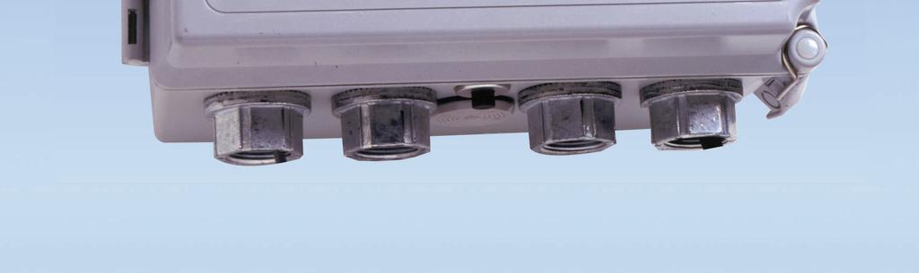
8 Chapter 2: Description Overview This chapter describes the GasScanner 4C s external and internal component. External Description This section describes the housing and all external components of the GasScanner 4C. For the purposes of this description, the housing door is considered the front of the monitor. Housing The GasScanner 4C s fiberglass housing is weather- and corrosion-resistant. It is suitable for installation where general purpose equipment is in use. The housing door is hinged on the left side and is secured by two latches on the right side. The LCD display and status LEDs are visible through windows in the housing door. Four mounting feet are attached to the back of the housing (one at each corner). The mounting feet allow you to install the housing to a vertical surface. Four conduit hubs on the bottom of the housing are for external wiring connections. CAUTION: To avoid electrical interference, do not route detector head and power wiring through the same conduit hub. Reset Switch The reset switch is on the bottom of the housing in front of the buzzer. The reset switch serves four functions: Resets the alarm circuits for latched alarms after an alarm 1, alarm 2, or alarm 3 condition passes. You can set each channel for latched or self-resetting alarms in the Configuration Menu. See Viewing and Changing Channel Parameters on page 38 for more information. Silences the buzzer during an alarm 1, alarm 2, or alarm 3 condition if the buzzer silence parameter in the Global Menu is set to CAN SILENCE BUZZER. See Viewing and Changing Global Parameters on page 35 for more information on setting the silence feature. Resets the strobe during an alarm 1, alarm 2, or alarm 3 condition if the strobe alarm setting parameters are set to Resettable STROBE in the Configuration Menu. See Viewing and Changing Channel Parameters on page 38 for more information on setting the strobe alarm setting parameters. Displays and resets the minimum and maximum gas concentration values detected. NOTE: Fail alarms cannot be reset or acknowledged with the reset switch. When a fail condition passes, the GasScanner 4C will automatically reset the fail alarm circuit. Buzzer The buzzer is on the bottom of the housing, behind the reset switch. The buzzer sounds an audible alarm to warn you of gas alarms and instrument failures. 8
9 Internal Description This section describes the internal components of the GasScanner 4C. Control PCB The control PCB (printed circuit board) is mounted to the power supply mounting plate which is in turn mounted to the main PCB. The power supply mounting plate and main PCB are described below. The control PCB includes the LCD display, the LCD contrast adjust pot, the status LEDs, and the program buttons.it is connected to the main PCB by the display cable which is a 20 conductor ribbon cable assembly. The display cable connects to a rectangular connector on the top edge of the control PCB and to the same type of connector labelled FRONT PANEL on the top edge of the main PCB. 9
10 LCD Display During normal operation, the four line display simultaneously indicates the target gas, current gas reading, and measuring unit of each active channel. The display also shows messages, settings, and other data when you are operating the various selection menus and operating modes. LCD Contrast Adjust Pot The LCD contrast adjust pot is located to the left of the LCD. If the LCD contrast is too dark or too light to read easily, use a small phillips screwdriver adjust it until you can easily read the LCD. Status LEDs The GasScanner 4C includes seven status LEDs that indicate the current status of the monitor: the RX & TX LEDs, the pilot LED, the fail LED, the alarm 1 LED, the alarm 2 LED, and the alarm 3 LED (see Figure 2). RX & TX LEDs These LED s indicate data being received (RX) and transmitted (TX) when the GasScanner 4C s Modbus output is operating. Pilot LED The PILOT LED is on when the GasScanner 4C is receiving incoming power, either AC or DC power. Fail LED The fail LED turns on when the GasScanner 4C is experiencing a fail condition. A fail condition can be caused by a failure within the GasScanner 4C or the detector heads wired to the GasScanner 4C (see Chapter 10: Maintenance on page 66). Alarm 1 LED The alarm 1 LED is on when the GasScanner 4C is experiencing an alarm 1 condition. 10
11 ALARM 2 LED The alarm 2 LED is on when the GasScanner 4C is experiencing an alarm 2 condition. ALARM 3 LED The alarm 3 LED is on when the GasScanner 4C is experiencing an alarm 3 condition. Control Buttons The GasScanner 4C includes four control buttons that allow you to enter the selection menus and Calibration Mode, navigate through the menus and Calibration Mode, update instrument and channel parameter settings, and save changes to the settings. The control buttons, listed in Table 2, are to the right of the LCD display (see Figure 2 ). Table 2: GasScanner 4C Control Button Functions Button Function ESCAPE Moves backward through the menu and mode screens Aborts operations Cancels changes you make in the menus Enters the Configuration Menu (press with ENTER button) Enters the Global Menu (press with the UP/YES button) UP (YES) Initiates an operation or proceeds to the next screen when a yes/no question is asked on a screen Changes the displayed setting Enters the Global Menu (press with ESCAPE) button Enters the Calibration Mode (press with ENTER button) DOWN (NO) Cancels an operation or sequence when a yes/no question is asked on a screen. Changes the displayed setting Enters the Modbus Menu (press with ENTER button) ENTER Saves changes you make in the menu and mode screens Accepts the displayed parameter setting Enters the Configuration Menu (press with ESCAPE button) Enters Calibration Mode (press with UP/YES button) Enters the Modbus Menu (press with DOWN/NO button) Main PCB Terminal Strips The GasScanner 4C includes 9 terminal strips for wiring connections. See Wiring the GasScanner 4C on page 16 for detailed wiring procedures. Strobe Terminal Strip The strobe terminal strip is a 2-point terminal strip located in the upper left corner of the main PCB. When the optional strobe is ordered with a GasScanner 4C, the strobe terminal strip is used to factory wire the strobe. 11
12 CAUTION: The strobe terminals are intended for use with the MTG supplied optional strobe. Consult Matheson Tri-Gas. before attempting to use these terminals for some other alarm device. Detector/Transmitter Terminal Strips Four detector/transmitter terminal strips are located along the bottom left side of the main PCB (see Figure 1 on page 9). These four 11-point terminal strips facilitate wiring connections to the detector heads. They also provide terminals to connect a recording device to a 4 to 20 ma output for each channel. The top terminal strip is for channel 1 connections and each subsequent strip is used for the next channel with the bottom terminal strip being for channel 4 connections. Channel Alarm Terminal Strip A channel alarm terminal strip is located to the right of the channel 4 detector/transmitter terminal strip (see Figure 1 on page 9). This 24-point terminal strip facilitates wiring external alarm devices (horn, light, etc.) to relay contacts that are field configurable for alarm levels and operation and are controlled by individual channels.the contacts are labelled NO (normally open), NC (normally closed), and C (common). See Viewing and Changing Global Parameters on page 35 and Viewing and Changing Channel Parameters on page 38 for instructions to configure the operation of these contacts. Common/Channel Alarm Terminal Strip The common/channel alarm terminal strip is located in approximately the middle of the main PCB above the channel alarm terminal strip. This 15-point terminal strip facilitates wiring external alarm devices (horn, strobe, etc.) to relay contacts that are field configurable as individual alarm contacts that are controlled by individual channels or as common alarm contacts which are controlled by all channels. The contacts are labelled NO (normally open), NC (normally closed), and C (common). See Viewing and Changing Global Parameters on page 35 and Viewing and Changing Channel Parameters on page 38 for instructions to configure the operation of these contacts. Controller terminal strip The 9-point controller terminal strip is along the lower right side of the main PCB (see Figure 1 on page 9). The controller terminal strip facilitates various internal and external wiring connections. Table 3 lists the function of each terminal. Table 3: Terminal Assignments for the Controller Terminal Strip (Continued) Terminal EXT DC/24V BATT + EXT DC/24V BATT - Connects to: + connection from 24 VDC power source1 (or 24 V backup battery)1 - connection from 24 VDC power source1 (or 24 V backup battery)1 RS-485 A RS-485 B Allow connection of the GasScanner 4C to a Modbus network RS-485 C Alarm Reset Reset Switch Terminals (factory wired) Alarm Reset Alarm Buzzer + Buzzer + connection (factory wired) Alarm Buzzer - Buzzer - connection (factory wired) If 24 VDC is used as primary power source do not make wiring connections to the AC terminal strip. 12
13 AC terminal strip The 3-point AC terminal strip is located above the controller terminal strip (see Figure 1 on page 9). The AC terminal strip facilitates wiring connections to the AC power source. Relays The GasScanner 4C includes eight channel relays and one common fail relay. It also includes four common/channel relays that can be defined as a group as channel or common relays. All the relays have single-pole double-throw (SPDT) contacts, also known as form C contacts, and are rated for 10 amps at 115 VAC (resistive). The contacts are available at the channel alarm and common/channel alarm terminal strips and are labelled NO (normally open), NC (normally closed), and C (common). Channel Relays & Fail Relay Figure 3: GasScanner 4C Relay Allocation The eight channel relays are above the channel alarm terminal strip (see Figure 1 on page 9 and Figure 3 on page 13). These relays are dedicated to specific channels. Figure 3 illustrates the allocation of the channel relays. The fail relay is located directly to the left of the channel relays. The fail relay is a common relay. Common/Channel Relays The four common/channel relays are above the common/channel alarm terminal strip (see Figure 1 on page 9 and Figure 3 on page 13). These relays can be configured as either all channel relays or all common relays in the Global Menu. 13
14 Termination Jumper A two pin header with a termination jumper installed is located near the top edge of the main PCB to the right of the display cable connector. It is labelled RS-485 Line Terminator on the PCB silkscreen. The jumper has no function unless the GasScanner 4C is wired into a Modbus installation. See Chapter 9: RS-485 Modbus Output on page 57 for a instructions to use the GasScanner 4C in a Modbus system. Ground Stud The threaded ground stud is used for making connections to earth ground. It is located in the lower right corner of the Main PCB and is connected through the main PCB to the G (ground) terminal on the AC terminal strip. A kep nut on the stud may be removed for installation of one or more user supplied lugs to make wiring connections to earth ground. This stud is typically used to connect the shield drain wire of shielded cable to earth ground at the GasScanner 4C. Power Switch The power switch is between the common/channel relays and the fuses (see Figure 1 on page 9 and Figure 3 on page 13). The power switch turns the incoming AC power source on and off at the GasScanner 4C. When the switch is up, the power is on. Power Supply The power supply is mounted to the power supply mounting plate which is located behind the display PCB. The power supply mounting plate is mounted to the main PCB with four standoffs. The power supply receives AC power from the external power source and converts it to a DC voltage that is usable by the GasScanner 4C circuitry. A polycarbonate cover prevents accidental contact with the AC terminals on the power supply. AC & DC Circuit Protection Two AC fuses are used in the GasScanner 4C. The two fuses are located on the right side of main PCB, between the power switch and the AC in terminal strip (see Figure 1 on page 9 and Figure 3 on page 13). They cut off the incoming AC power in the event of a short circuit or other electrical fault which causes a high current draw in the GasScanner 4C. They are housed in vertical fuse holders and are held in each holder by a quarter turn cover. They are fast blow fuses rated at 6 A, 250 V. A polyswitch is used to protect the DC power input. It is located on the right side of the main PCB above the AC fuses and is labelled on the PCB silkscreen as PS9. In the event of a short circuit or other electrical fault which causes a high current draw in the GasScanner 4C, the polyswitch will interrupt the DC power if the unit is powered from DC. When the fault situation is corrected, the polyswitch resets and the unit will continue to operate. The polyswitch is not user serviceable. 14
15 Chapter 3: Installation and Start Up Overview This chapter describes procedures to mount the GasScanner 4C Gas Monitor, make wiring connections to the monitor, and start up the monitor. WARNING: Perform all installation and start-up procedures in a known fresh air environment, an environment free of combustible and toxic gasses and of normal oxygen content. The GasScanner 4C is not in operation as a gas monitoring controller until the start up procedure is complete. Mounting the GasScanner 4C Gas Monitor Perform the following procedure to install the GasScanner 4C at the mounting site. 1. Select the mounting site. When you select the mounting site, consider the following factors: Is an AC or DC power source available? Is a vertical surface available to mount the GasScanner 4C? Is there enough room to open the housing door and make wiring connections through the conduit hubs at the bottom of the housing? Are the display screen and status lights visible? 2. Close and latch the housing door. 3. The GasScanner 4C is shipped with the mounting feet positioned under the housing. Loosen the screws that secure the feet to the housing, rotate the feet to their mounting position as shown in Figure, then tighten the screws. 4. Prepare the selected mounting site as required to mount the GasScanner 4C. It should be mounted at eye level (4 1/2 to 5 feet from the floor). Refer to Figure 4 for the outline and mounting dimensions. 5. Position the monitor on the vertical mounting surface. 6. Insert 1/4 in. screws through the slots in the mounting feet at each corner of the housing to secure the housing to the mounting surface. 15
16 Figure 4: GasScanner 4C Gas Monitor Outline and Mounting Dimensions Wiring the GasScanner 4C Gas Monitor This section describes procedures to connect the AC power source, DC power source, Modbus wiring (refer to Wiring the GasScanner 4C in a Modbus System on page 57), external alarms, recording devices, and detector heads. See Figure 5 on page 17 for a general diagram of all external wiring to the GasScanner 4C. WARNING: Make all connections to the GasScanner 4C before you plug in or turn on the AC or DC power source. Before you make any wiring adjustments, always verify that all power sources are not live. 16
17 Optional Strobe Common / Channel Alarm Terminal Strip FAIL RELAY-A NO NC C NO NC C RELAY-B NO NC C RELAY-C NO NC C RELAY-D NO NC C Alarm Device Power AC In Terminal Strip AC L N Line (Hot) Neutral G Ground AC Power 100/115 VAC 50 / 60 Hz NOTE: Line and Neutral are L1 and L2 for 220 VAC W iring Red Black Controller Terminal Strip Strobe Terminal Strip (Factory wired) DP S W Not Used Alarm Devices, Typical Alarm Wiring Shown Relay Contacts Rated For10 Amps At 250 VAC EXT DC 24V BATT A RS B C 24V DC See ModbusWiring In Chapter 9 Detector / Transmitter Terminal Strip (typical 1 of 4) AMP S OXY W G R LEL W G B 4-20 ma OUTPUT CH 1 RELAY-1 CH 1 RELAY-2 NO NC C NO NC C Channel Alarm Terminal Strip CH 2 RELAY-1 NO NC C CH 2 RELAY-2 NO NC C CH 3 RELAY-1 NO NC C CH 3 RELAY-2 NO NC C CH 4 RELAY-1 NO NC C CH 4 RELAY-2 NO NC C ALARM RESET ALARM BUZZER Reset Switch (Factory wired) Buzzer (Factory wired) Refer to Detector Head Manual And Beacon 410 Detector Head Specification Sheet for Specific Detector/Transmitter Wiring Recording Device 500 Ohms Impedance Maximum Alarm Devices, Typical Alarm Wiring Shown Relay Contacts Rated For10 Amps At 250 VAC Alarm Device Power Figure 5: Beacon 410 Gas Monitor External Wiring Diagram Beacon 410 Gas Monitor Operator s Manual Wiring the Beacon 410 Gas Monitor 17
18 Connecting the AC Power Source NOTE: If you are using DC power as the primary power source, go to the next section, Connecting the DC Power Source. The AC in terminal strip will accept AWG wire. When selecting wire to connect the AC power source to the GasScanner 4C, be sure to meet the local electrical code. Also be sure to use an appropriate circuit breaker in the AC line close to the GasScanner 4C that meets the local electrical code. Perform the following procedure to connect the AC power source to the GasScanner 4C. WARNING: Verify that the power source is unplugged or turned off before you continue with this procedure. 1. Turn off or unplug all incoming power to the GasScanner 4C. 2. Open the housing door, then place the power switch in the OFF position. CAUTION: The power switch does not control DC input power. 3. Locate the AC in terminal strip (see Figure 1 on page 9). The terminals are labelled L, N, and G for line, neutral, and ground respectively. 4. Install an appropriately rated cable bushing or conduit in the right-most conduit hub on the bottom of the GasScanner 4C housing. 5. Guide the AC power cord or wires in conduit through the right-most conduit hub on the bottom of the GasScanner 4C housing. CAUTION: Do not route power and detector head wiring through the same conduit hub. The power wiring may disrupt the transmission of the detector head signal to the monitor. 6. Connect the AC wires to the AC in terminal strip as shown in Figure 6 below. Connecting the DC Power Source Figure 6: AC Power Wiring WARNING: Verify that the power source is unplugged or turned off before you continue with this procedure. 18
19 DC power may be used as a primary power source. It may also be used as a backup power source with a 24 VDC battery if AC power is the primary power source. If your GasScanner 4C does not include the battery charging feature, you may use a self contained 24 VDC backup that keeps its batteries charged while AC power is on and recharges the batteries when AC power returns after a power failure. If your GasScanner 4C includes the battery charging feature, see Battery Charging (Optional) on page 28 for a complete description of this feature and what type of battery to use. If DC power is the primary power source, DO NOT connect AC power. 1. Turn off or unplug all incoming power to the GasScanner 4C. 2. Open the housing door, then place the power switch in the OFF position. CAUTION: The power switch does not control DC input power. 3. Locate the DC input power terminals on the controller terminal strip near the lower right edge of the main PCB (see Figure 1 on page 9). They are labelled EXT DC/24V BATT+ and EXT DC/24V BATT Install an appropriately rated cable bushing or conduit in an unused conduit hub on the bottom of the GasScanner 4C housing. 5. Guide a DC power cord or two wires in conduit through the selected conduit hub on the bottom of the GasScanner 4C housing. CAUTION: Do not route power and detector head wiring through the same conduit hub. The power wiring may disrupt the transmission of the detector head signal to the monitor. 6. Connect the DC power wires to the controller terminal strip as shown in Figure 7 below. NOTE: The GasScanner 4C will operate from the DC input down to 18.5 volts. If a self contained backup battery is used, see its operator s manual for a description of its recharging characteristics. If your GasScanner 4C includes the battery charging feature and a backup battery is used, the GasScanner 4C will recharge the battery when AC power has returned after a power failure. See Battery Charging (Optional) on page 28 for a complete description of the battery charging feature. RS-485 Modbus Wiring See Wiring the GasScanner 4C in a Modbus System on page 57 for wiring connections to the RS- 485 Modbus terminals. 19
20 Connecting External Alarms Before connecting any external alarm devices to the relay contacts, make sure you know how you want the devices to operate. For example, confirm under what alarm condition you want a device to turn on or turn off and what channel is going to control the device. Also make sure that the parameter settings that apply to the relays in the Global Menu and the Configuration Menu are set so that the desired alarm device operation is obtained. See Viewing and Changing Global Parameters on page 35 and Viewing and CXhanging Channel Parameters on page 38 for information about the relay parameters. Perform the following procedure to connect external alarm devices to the GasScanner 4C. 1. Turn off or unplug all incoming power to the GasScanner 4C. 2. Open the housing door, then place the power switch in the OFF position. CAUTION: The power switch does not control DC input power. 3. Locate the applicable alarm terminal strip (see Figure 1 on page 9). 4. Install an appropriately rated cable bushing or conduit in an unused conduit hub on the bottom of the GasScanner 4C. 5. Guide the wiring of the external alarm device through the selected conduit hub on the bottom of the GasScanner 4C housing. CAUTION: Do not route the external alarm wiring and detector head wiring through the same conduit hub. The external alarm wiring may disrupt the transmission of the detector head signal to the GasScanner 4C. 6. Connect the leads from the external alarm device and an external power source to the selected channel alarm or common/channel alarm relay contact terminals as shown in Figure 8. Figure 8: External Alarm Wiring 7. Repeat step 5 and step 6 for additional external alarm devices. Connecting Recorders Perform the following procedure to connect an analog signal recording device to the GasScanner 4C. The output at the recorder output terminals for each channel is a 4-20 ma signal that corresponds to the detection range of the detector head connected to that GasScanner 4C channel. Be sure to read the recording device s operator s manual before installation and follow all wiring procedures and recommendations made by the recording device s manufacturer. 20
21 1. Turn off or unplug incoming power to the GasScanner 4C. 2. Open the housing door, then place the power switch in the OFF position. CAUTION: The power switch does not control DC input power. 3. Locate the recorder output terminals on the right end of the detector/transmitter terminal strips. See Figure 1 on page 9 to assist you in locating the recorder output terminals. They are labelled 4-20 ma OUTPUT + and 4-20 ma OUTPUT Install an appropriately rated cable bushing or conduit in an unused conduit hub on the bottom of the GasScanner 4C housing. 5. Guide the wiring from the recording device through the selected conduit hub on the bottom of the GasScanner 4C housing. 6. Connect the leads from the recording device to the recorder output terminals of the selected active channels as shown in Figure below. Connecting Matheson Tri-Gas Detector Heads When a GasScanner 4C is ordered from the factory, any detector heads that were ordered with it are already setup on particular channels of the GasScanner 4C. If you are adding a MTG detector head to your existing system, you will need to setup one of the unused channels to operate the detector head. See Selecting the Detector Head Input Type and Gas Setup on page 44 for instructions to setup a new channel. Perform the following procedure to connect an MTG detector head to the GasScanner 4C. 1. Turn off or unplug power to the GasScanner 4C. 2. Open the GasScanner 4C door and place the power switch in the off position. CAUTION: The power switch does not control DC input power. 3. See the detector head operator s manual for instructions on how to connect the detector head to a controller. 4. Install an appropriately rated cable bushing or conduit in an unused conduit hub on the bottom of the GasScanner 4C housing. 21
22 5. Route the wires in conduit or shielded cable from the detector head through the selected conduit hub into the GasScanner 4C. See Table 4 below for wire size and distance guidelines. 6. Unshielded twisted pair cable in conduit or shielded twisted pair cable is recommended for all the direct connect detector heads. For the LEL detector, pair and twist the R & B wires and the W & G wires. Shielded cable or wires in conduit are recommended for the 2-wire and 3-wire 4-20 ma transmitters. 7. Connect the wires from the detector head to the appropriate detector/transmitter terminals on the appropriate channel. See the detector head operator s manual and the GasScanner 4C Detector Head Specification Sheet for detector head connections to the GasScanner 4C. If shielded cable is used, leave the cable shield s drain wire disconnected and insulated at the detector head and connect the cable shield s drain wire at the GasScanner 4C to the ground stud on the main PCB. CAUTION: Do not route power and detector head wiring through the same conduit hub. The power wiring may disrupt the transmission of the detector head s signal to the GasScanner 4C. Table 4: Wire Size Guidelines for MTG Detector Head Wiring (Continued) Detector Head Type Number of Wires to Controller Max Distance to Controller w/18 Gauge Wire Max Distance to Controller w/16 Gauge Wire Max Distance to Controller w/14 Gauge Wire Direct Connect LEL ft. 1,000 ft. 2,000 ft. Direct Connect Oxygen ft. 1,000 ft. 2,000 ft. Direct Connect H2S ft. 1,000 ft. 2,000 ft. Direct Connect CO ft. 1,000 ft. 2,000 ft. Direct Connect ESM-01 type ft. 1,000 ft. 2,000 ft. 2-Wire 4-20 ma Transmitter 2 2,500 ft. 5,000 ft. 8,000 ft. 3-Wire 4-20 ma Transmitter 3 2,500 ft. 5,000 ft. 8,000 ft. Connecting User-Supplied 4-20 ma Transmitters The GasScanner 4C may be used with a user supplied 2-wire or 3-wire 4-20 ma transmitter which runs on 24 VDC. When this is done, the GasScanner 4C is normally setup at MTG Instruments with the following channel parameters: unit of measure, item name, and full scale. For example, PSI AIR with a full scale of 10 PSI. If a user supplied 4-20 ma transmitter is added in the field, it will be necessary to setup the additional channel. See Selecting the Detector Head Input Type and Gas Setup on page 44 for instructions to setup a new channel. Perform the following procedure to connect a 4-20 ma transmitter which you supply to the GasScanner 4C. 1. Turn off or unplug power to the GasScanner 4C. 22
23 2. Open the GasScanner 4C door and turn off the power switch. CAUTION: The power switch does not control DC input power. 3. See the transmitter s operator s manual for instructions on how to connect wires to the transmitter. 4. Install an appropriately rated cable bushing or conduit in an unused conduit hub on the bottom of the GasScanner 4C housing. 5. Route the wires from the transmitter through the selected conduit hub into the GasScanner 4C. 6. Connect the wires from the transmitter to the appropriate channel s detector/transmitter terminal strip. See the transmitter operator s manual for controller terminal connections and wiring recommendations. CAUTION: Do not route power and transmitter wiring through the same conduit hub. The power wiring may disrupt the transmission of the transmitter s signal to the GasScanner 4C. Figure 10 below illustrates typical transmitter wiring connections. 23
24 Starting Up the GasScanner 4C Gas Monitor Perform the following procedure to place the GasScanner 4C into normal operation. 1. Complete the mounting and wiring procedures described earlier in this chapter. 2. Complete all installation procedures described in the detector head or user supplied 4-20 ma transmitter operator s manuals. 3. Verify that all wiring connections are correct and secure and that the GasScanner 4C s power switch is in the OFF position. 4. Plug in or turn on the incoming power source (AC or DC). 5. Turn on the power switch if AC power is used as primary power. 6. The following screen appears for a few seconds. 7. The Version Screen then appears. It shows the instrument s hardware and firmware versions for a few seconds. HW is the hardware version. Main is the main firmware version. MB is the Modbus firmware version. The version numbers on the bottom line are the firmware versions loaded for each channel. To keep the version information screen on the display longer than a few seconds, press and hold the ENTER button while it is being displayed. When you release the ENTER button, the startup sequence will continue. 8. After the Version Screen has been displayed for a few seconds, WARMING UP appears for each active channel. The warm-up time is counted down in seconds from 60 seconds for each active channel on the far right. NOTE: To prevent unwanted alarms during warm up, the alarm circuits are not active while the WARMING UP message is displayed. 9. Any unused channels are configured as NOT USED in the Configuration Menu at the factory. For any unused channels, NOT USED is displayed on the line for that channel. If any channels have been configured as STANDBY in the Configuration Menu, STANDBY is displayed on the line for that channel. 24
25 See Viewing and Changing Channel Parameters on page 38 for a description of the NOT USED and STANDBY configurations. 10. When the warm-up period is complete, normal operation will begin. During normal operation, the display will indicate the current gas reading and target gas. Verify that the display is indicating the current gas reading and target gas for all active channels after the warm-up period is complete and normal operation begins, for example: 11. Verify that the PILOT light is on. If the PILOT light is not on, see the troubleshooting guide in Troubleshooting on page Perform the start-up procedure for each detector head or user supplied 4-20 ma transmitter as described in the detector head or user supplied transmitter s operator s manual. 25
26 Chapter 4: Operation Overview Normal Operation This chapter describes the GasScanner 4C Gas Monitor in normal operation. This chapter also describes the GasScanner 4C in alarm 1, alarm 2, alarm 3, and fail conditions, and suggests responses to these conditions. Normal operation is defined as follows: the start-up procedure is complete. the GasScanner 4C is not indicating an alarm 1, alarm 2, alarm 3, or fail condition. the GasScanner 4C is not running in one of the selection menus or Calibration Mode. During normal operation, the GasScanner 4C simultaneously displays the target gas, unit of measure, and current gas reading for all active channels. The example below illustrates a typical GasScanner 4C channel allocation. The PILOT LED is on indicating that the GasScanner 4C is receiving incoming power ma Signal Output Operation The output at the recorder output terminals on the detector/transmitter terminal strip for each channel is a 4-20 ma signal that corresponds to the detection range of the GasScanner 4C. During normal operation, this signal tracks the gas concentration on the LCD. There are several circumstances where the signal output will not track the display reading but will behave as follows: When the GasScanner 4C is in its warm-up period, the signal output will be fixed at 4 ma (zero) for all channel types except oxygen. For oxygen channels, the output will be fixed at 17.4 ma (20.9% oxygen) while the GasScanner 4C is in warm-up. When a channel s input type is changed to a new direct connect type of detector head in the Input Setup Menu, the display will indicate NEEDS AIR/GAS Cal for that channel when you exit the Input Setup Menu and enter normal operation and will continue to indicate this until Calibration Mode is entered and a calibration is performed. If a custom gas name and range was defined in the Input Setup Menu, the GasScanner 4C will enter the Configuration Menu for you to verify the parameter settings before continuing to the normal operation and displaying the NEEDS AIR/GAS Cal message. In this situation, the signal output for the newly configured channel will be fixed at 0.7 ma until a complete calibration is performed on that channel. 26
27 If you enter the Global Menu, the Configuration Menu, the Input Setup Menu, the Modbus Menu, or Calibration Mode, the signal output will be fixed at 3.5 ma until the GasScanner 4C returns to normal operation. If the GasScanner 4C s input power decreases below 18.5 volts so that the GasScanner 4C is in a low power alarm, the signal output is fixed at 0.7 ma until the low power alarm is cleared. If the GasScanner 4C goes into a fail condition, the signal output is fixed at 0.7 ma until the fail alarm is cleared. If a channel is setup as NOT USED, the signal output will be fixed at about 0.7 ma. If a channel is setup as STANDBY, the signal output will be fixed at 3.5 ma. Viewing and Resetting Min/Max Readings The Reset switch may be used to view and reset the minimum and maximum gas readings for all active channels. 1. While the GasScanner 4C is in normal operation, press and hold the reset switch button for 5 seconds. 2. The display will show the following screen for about ten seconds. The minimum reading is on the left and the maximum is on the right for each channel. 1. After the minimum and maximum readings have been displayed for about ten seconds, the following screen appears for about seven seconds. To reset the minimum and maximum readings, before the unit returns to normal operation press and release the reset switch button. The display indicates Min/ Max Values Have Been Reset and the unit will then return to normal operation. To return to normal operation without resetting the minimum and maximum readings, do not press the reset switch button and allow the unit to return to normal operation. 27
28 Battery Charging (Optional) The GasScanner 4C has an optional backup battery charging feature. In order for this feature to be included, the GasScanner 4C must be ordered with this feature. Consult Matheson Tri-Gas. for ordering information. The battery charging circuit is designed to charge lead acid type batteries. If AC power is used as primary power and a backup battery is connected to the GasScanner 4C s EXT DC/ 24V BATT terminals as shown in Figure 1 on page 9 the battery charging feature will charge the battery if it is depleted and keep it charged with a charge current of approximately 100 ma. CAUTION: When a battery is used as backup power and the charging feature is included in the GasScanner 4C, do not use a non-rechargeable battery or a backup battery that has it s own charging feature. Use MTG backup battery RK or an appropriately rated 24 VDC rechargeable lead acid type battery to backup a GasScanner 4C when the battery charging feature is included in the GasScanner 4C. Alarm Indications This section describes the GasScanner 4C in alarm 1, alarm 2, alarm 3 and fail conditions, and suggests responses to these conditions. Table 5 below lists the alarm indications for each condition. NOTE: The GasScanner 4C allows configuration of various alarm and alarm relay parameters. The description of alarm indications below assumes that all parameters are at their factory set value. It also assumes that the alarm setpoints are set such that alarm 1< alarm 2 < alarm 3 and all alarms are increasing except for an oxygen channel where alarm 1>alarm 3 and alarm 2 > alarm 3 because alarm 1 and alarm 3 are decreasing alarms and alarm 2 is an increasing alarm. See Viewing and Changing Channel Parameters on page 38 for detailed information on displaying or changing various channel parameters including alarm and alarm relay parameters. Table 7 on page 40 lists the adjustable parameters and their factory settings. 28
29 Table 5: Visual and Audible Alarm Indications Condition Cause Visual Indication(s) Audible Indication Alarm 1 Increasing (decreasing for O 2) gas Alarm 1 LED is on Pulsing Tone reading at or above the alarm 1 setpoint Gas reading alternates with ALARM-1 message If installed and set to activate for alarm 1, strobe flashes Alarm 2 Increasing gas reading at or above the Alarm 1 and alarm 2 LEDs Pulsing Tone alarm 2 setpoint (alarm 2 only for oxygen) are on Gas reading alternates with ALM 1,2 message (ALARM-2 for oxygen) If installed, strobe continues to flash if set to activate for alarm 1. If set to activate for alarm 2 only or if channel in alarm is an oxygen channel, it begins to flash when an alarm 2 condition begins. Alarm 3 Increasing (decreasing for O2) gas Alarm 1, alarm 2, and alarm 3 Pulsing tone reading at or above (below for O2) the LEDs (alarm 1 and alarm 3 for alarm 3 setpoint oxygen) are on Gas reading alternates with ALM 1,2,3 (ALM 1,3 for oxygen) message If installed, strobe continues to flash if set to activate for alarm 1 and/or alarm 2 for non oxygen type channels or alarm 1 for oxygen channels. If set to activate for alarm 3 only, it begins to flash when an alarm 3 condition begins. Fail Disconnected or misconnected Fail LED is on Steady tone detector head wiring FAIL message replaces the gas Display reading below -10% of full reading scale or lower If installed and set to activate for Malfunctioning components fail, strobe flashes Low Battery No AC power and DC power source FAIL LED is on None (primary or backup) less than 18.5 volts. Display shows LOW POWER STANDBY message and the input DC voltage 29
30 NOTE: You can set the channel alarm relays and the common/channel alarm relays (relays A, B, C, and D) to be either all normally energized or all normally de- energized in the Global Menu. You can also set relays A, B, C, and D as common alarm relays or channel alarm relays in the Global Menu. The following sections describe the factory settings of normally deenergized for the channel and common/channel relays (A, B, C, and D) and common alarm relays for relays A, B, C, and D. The fail relay is factory-set as normally energized and is not user adjustable. See Viewing and Changing Global Parameters on page 35 for instructions to change the setup of relays A, B, C, and D. Alarm 1 Condition This section describes the indications for an alarm 1 condition and suggests responses to an alarm 1 condition. Alarm 1 condition indications When the gas reading of an active channel reaches the alarm 1 setpoint, the GasScanner 4C senses an alarm 1 condition. The GasScanner 4C alerts you to an alarm 1 condition as follows: the alarm 1 LED turns on the gas reading in alarm 1 condition alternates with the ALARM-1 message the buzzer sounds a pulsing tone the common alarm 1 relay (relay A) and relay D energize NOTE: Relay D is factory set as a common any alarm relay. the applicable alarm 1 channel relay energizes if installed and set to activate in an alarm 1 condition, the strobe flashes Responding to an alarm 1 condition This section suggests the following responses to an alarm 1 condition: 1. Follow your established procedure for a low-level combustible or toxic gas condition or a decreasing oxygen condition. 2. To acknowledge the alarm condition and silence the buzzer while in an alarm 1 condition, press and release the reset switch. The alarm 1 LED will begin to flash indicating the alarm condition has been acknowledged. You cannot de-energize the alarm 1 relays until the gas reading falls below (rises above for oxygen) the alarm 1 setpoint. 3. After the gas reading falls below (rises above for oxygen) the alarm 1 setpoint, press and release the reset switch to reset the alarm 1 circuit. Resetting the alarm 1 circuit silences the buzzer (if the alarm has not been acknowledged), turns off the alarm 1 LED, resets the display for the channel(s) in alarm, turns off the strobe if it is installed and set to activate for alarm 1, and deenergizes the common and channel alarm 1 relays and relay D. 30
31 Alarm 2 Condition This section describes the indications for an alarm 2 condition and suggests responses to an alarm 2 condition. Alarm 2 condition indications When the gas reading of an active channel reaches the alarm 2 setpoint, the GasScanner 4C senses an alarm 2 condition. The GasScanner 4C alerts you to an alarm 2 condition as follows: the ALARM 2 LED turns on the gas reading during an alarm 2 condition alternates with the ALM 1,2 (ALARM-2 for oxygen) message the buzzer sounds a pulsing tone the common alarm 2 relay (relay B) energizes for an oxygen channel, relay D energizes (it is already energized for non-oxygen channels) the applicable alarm 2 channel relay energizes if installed and set to activate for alarm 1, the strobe continues to flash for non-oxygen channels if installed and set to activate for alarm 2 only or for oxygen channels, the strobe begins to flash when an alarm 2 condition begins Responding to an alarm 2 condition This section suggests responses to an alarm 2 condition. 1. Follow your established procedure for a high-level combustible or toxic gas condition, or an increasing oxygen condition. 2. To acknowledge the alarm condition and silence the buzzer while in an alarm 2 condition, press and release the reset switch. The alarm 2 LED will begin to flash indicating the alarm condition has been acknowledged. You cannot de-energize the alarm 2 relays until the gas reading falls below the alarm 2 setpoint. 3. After the gas reading falls below the alarm 2 setpoint, press and release the reset switch to reset the alarm circuit. Resetting the alarm circuit silences the buzzer (if the alarm has not been acknowledged) turns off the alarm 2 LED, resets the display for the channel(s) in alarm, turns off the strobe if it is installed and set to activate for alarm 2 only or if a channel is an oxygen channel, and de-energizes the common and channel alarm 2 relays. For oxygen channels, the reset switch also de-energizes relay D. 31
32 Alarm 3 Condition This section describes the indications for an alarm 3 condition and suggests responses to an alarm 3 condition. NOTE: The factory set configuration of the GasScanner 4C does not assign channel relay contacts to the alarm 3 condition. Relays A, B, C, and D are factory set as common alarm relays, but can be configured as channel alarm 3 relays. See Viewing and Changing Global Parameters on page 35 and Viewing and Changing Channel Parameters on page 38 for instructions to change relays A, B, C, and D from their factory setting. Alarm 3 condition indications When the gas reading of an active channel reaches the alarm 3 setpoint, the GasScanner 4C senses an alarm 3 condition. The GasScanner 4C alerts you to an alarm 3 condition as follows: the alarm 3 LED turns on; the gas reading during an alarm 3 condition continues to flash and alternates with the ALM 1,2,3 (ALM 1,3 for oxygen) message; the buzzer sounds a pulsing tone; the common alarm 3 relay (relay C) energizes if installed and set to activate for alarm 1 and/or alarm 2 for non-oxygen channels or alarm 1 for oxygen channels, the strobe continues to flash if set to activate for alarm 3 only, it begins to flash when an alarm 3 condition begins Responding to an alarm 3 condition This section suggests responses to an alarm 2 condition. 1. Follow your established procedure for a high-level combustible or toxic gas condition, or an increasing oxygen condition. 2. To acknowledge the alarm condition and silence the buzzer while in an alarm 3 condition, press and release the reset switch. The ALARM 3 LED will begin to flash indicating the alarm condition has been acknowledged. You cannot de-energize the common alarm 3 relay (relay C) until the gas reading falls below the alarm 3 setpoint. 3. After the gas reading falls below the alarm 3 setpoint, press and release the reset switch to reset the alarm circuit. Resetting the alarm circuit silences the buzzer (if the alarm has not been acknowledged) turns off the ALARM 3 LED, and de-energizes the common alarm 3 relay. 32
Beacon 410A Gas Monitor Operator s Manual
 Beacon 410A Gas Monitor Operator s Manual Part Number: 71-0397 Revision: F Released: 12/5/17 www.rkiinstruments.com Product Warranty RKI Instruments, Inc., warrants gas alarm equipment sold by us to be
GasScanner 1C. Single Channel Monitor. Operator s Manual. MINT-0278-XX Rev A
 GasScanner 1C Single Channel Monitor Operator s Manual MINT-0278-XX Rev A Product Warranty Matheson Tri-Gas, Inc., warrants gas alarm equipment sold by us to be free from defects in materials, workmanship,
Beacon 800 Gas Monitor Operator s Manual
 Beacon 800 Gas Monitor Operator s Manual Part Number: 71-0037RK Revision: F Released: 4/18/17 www.rkiinstruments.com Product Warranty RKI Instruments, Inc. warrants gas alarm equipment sold by us to be
Beacon 110 Gas Monitor Operator s Manual
 Beacon 110 Gas Monitor Operator s Manual Part Number: 71-0110RK Revision: H Released: 12/5/17 RKI Instruments, Inc. www.rkiinstruments.com Product Warranty RKI Instruments, Inc., warrants gas alarm equipment
Beacon 200 Gas Monitor Operator s Manual. Part Number: RK Released: 6/6/08
 Beacon 200 Gas Monitor Operator s Manual Part Number: 71-2102RK Released: 6/6/08 Table of Contents Chapter 1: Introduction.................................................3 Overview.............................................................3
GasScanner 8C. Eight Channel Monitor. Operator s Manual. MINT-0281-XX Rev. A 01/29/08
 GasScanner 8C Eight Channel Monitor Operator s Manual MINT-0281-XX Rev. A 01/29/08 Product Warranty Matheson Tri-Gas, Inc., warrants gas alarm equipment sold by us to be free from defects in materials,
Beacon 200 Gas Monitor Operator s Manual
 Beacon 200 Gas Monitor Operator s Manual Part Number: 71-0059RK Revision: J Released: 1/31/18 www.rkiinstruments.com Product Warranty RKI Instruments, Inc. warrants gas alarm equipment sold by us to be
Sample Draw Aspirator Adapter Operator s Manual
 30-0954-265-01 Sample Draw Aspirator Adapter Operator s Manual Part Number: 71-0464 Revision: P1 Released: 9/26/18 RKI Instruments, Inc. www.rkiinstruments.com Product Warranty RKI Instruments, Inc., warrants
Combustible Gas and Hydrogen Sulfide Beacon 200 Rig Monitor Operator s Manual
 Combustible Gas and Hydrogen Sulfide Beacon 200 Rig Monitor Operator s Manual Part Number: 71-0243RK Revision: E Released: 12/11/17 www.rkiinstruments.com WARNING Read and understand this instruction manual
RK-HC-04 M2A Transmitter Operator s Manual
 65-2649RK-HC-04 M2A Transmitter Operator s Manual Part Number: 71-0327 Revision: B Released: 9/20/18 RKI Instruments, Inc. www.rkiinstruments.com WARNING Read and understand this instruction manual before
RK-04 M2 Transmitter Operator s Manual
 65-2610RK-04 M2 Transmitter Operator s Manual Part Number: 71-0294RK Revision: 0 Released: 12/27/13 RKI Instruments, Inc. www.rkiinstruments.com WARNING Read and understand this instruction manual before
Pioneer-R16 Gas Monitor Operator s Manual
 Pioneer-R16 Gas Monitor Operator s Manual Edition 7/2/97 RKI INSTRUMENTS, INC RKI Instruments, Inc. 33248 Central Ave, Union City, CA 94587 (510) 441-5656 Chapter 1: Description About the Pioneer-R16 Gas
RK-OXY Oxygen Sample-Draw Detector Operator s Manual Part Number: RK Revision: P1 Released: 7/18/02
 35-3000RK-OXY Oxygen Sample-Draw Detector Operator s Manual Part Number: 71-0071RK Revision: P1 Released: 7/18/02 RKI Instruments Inc. 1855 Whipple Road Hayward, CA 94544 PH: 800-754-5165 Fax: 510-441-5650
M2 Rig Monitor Operator s Manual
 M2 Rig Monitor Operator s Manual Part Number: 71-0234RK Revision: D Released: 9/30/14 RKI Instruments, Inc. www.rkiinstruments.com WARNING Read and understand this instruction manual before operating instrument.
Carbon Dioxide Sample-Draw Detector Operator s Manual
 35-3001-05-03 Carbon Dioxide Sample-Draw Detector Operator s Manual Part Number: 71-0413 Revision: 0 Released: 8/4/17 www.rkiinstruments.com WARNING Read and understand this instruction manual before operating
RK Carbon Monoxide Transmitter Operator s Manual
 65-2434RK Carbon Monoxide Transmitter Operator s Manual Part Number: 71-0061RK Edition: First, Revision C Released: December 2001 65-2434RK CO Transmitter 1 Product Warranty RKI Instruments, Inc., warranties
RK-05 Combustible Gas Transmitter Operator s Manual
 65-2405RK-05 Combustible Gas Transmitter Operator s Manual Part Number: 71-0180RK Revision: 0 Released: 2/16/11 RKI Instruments, Inc. www.rkiinstruments.com WARNING Read and understand this instruction
Combustible Gas Sample-Draw Detector Operator s Manual
 35-3001-01 Combustible Gas Sample-Draw Detector Operator s Manual Part Number: 71-0282RK Revision: A Released: 8/3/17 www.rkiinstruments.com WARNING Read and understand this instruction manual before operating
RK Combustible Gas Transmitter Operator s Manual
 65-2400RK Combustible Gas Transmitter Operator s Manual Part Number: 71-0060RK Revision: C Released: 1/31/13 www.rkiinstruments.com WARNING Read and understand this instruction manual before operating
RK Carbon Monoxide Transmitter Operator s Manual
 65-2432RK Carbon Monoxide Transmitter Operator s Manual Part Number: 71-0070RK Revision: P1 Released: July 8, 2001 RKI Instruments, Inc. 1855 Whipple Road Hayward CA 94544 Phone: 800-754-5165 Fax: 510-441-5650
RK Hydrogen Sulfide Transmitter Operator s Manual
 65-2331RK Hydrogen Sulfide Transmitter Operator s Manual Part Number: 71-0176RK Revision: B Released: 11/26/14 RKI Instruments, Inc. www.rkiinstruments.com WARNING Read and understand this instruction
RK CO 2 Transmitter Operator s Manual
 65-2397RK CO 2 Transmitter Operator s Manual Part Number: 71-0185RK Revision: B Released: 7/18/14 RKI Instruments, Inc. www.rkiinstruments.com WARNING Read and understand this instruction manual before
RK Transmitter Technical Notice
 65-2450RK Transmitter Technical Notice Although this Operator s Manual was written for the 65-2400RK combustible gas LEL transmitter, the operational instructions are the same for the 65-2450RK hydrogen
RK/ RK Carbon Monoxide Detector Operator s Manual
 65-2496RK/65-2499RK Carbon Monoxide Detector Operator s Manual Part Number: 71-0156RK Revision: 0 Released: 2/16/11 www.rkiinstruments.com WARNING Read and understand this instruction manual before operating
RK/ RK Oxygen Detector Operator s Manual
 65-2502RK/65-2510RK Oxygen Detector Operator s Manual Part Number: 71-0074RK Revision: A Released: 3/1/11 www.rkiinstruments.com WARNING Read and understand this instruction manual before operating detector.
RK / RK Methane Detector Operator s Manual
 61-1006RK / 61-0192RK Methane Detector Operator s Manual Part Number: 71-0228RK Revision: 0 Released: 10/29/18 www.rkiinstruments.com WARNING Read and understand this instruction manual before operating
Tox-COMB/ANA Combustible Gas Transmitter Operator s Manual
 Tox-COMB/ANA Combustible Gas Transmitter Operator s Manual Part Number: 71-0132TA Revision: A Released: 4/23/10 www.toxalert.com Product Warranty Toxalert International, Inc. warrants gas alarm equipment
CT-7 Series Toxic Gas Transmitter Operator s Manual
 65-2341 CT-7 Series Toxic Gas Transmitter Operator s Manual Part Number: 71-0424 Revision: P1 Released: 6/8/17 RKI Instruments, Inc. www.rkiinstruments.com WARNING Read and understand this instruction
RK Carbon Monoxide Transmitter Operator s Manual
 65-2335RK Carbon Monoxide Transmitter Operator s Manual Part Number: 71-0177RK Revision: 0 Released: 4/12/11 RKI Instruments, Inc. www.rkiinstruments.com WARNING Read and understand this instruction manual
RK-03 Hydrogen Detector Operator s Manual
 61-1001RK-03 Hydrogen Detector Operator s Manual Part Number: 71-0371 Revision: P1 Released: 5/26/15 www.rkiinstruments.com WARNING Read and understand this instruction manual before operating detector.
RK/ RK Oxygen Detector Operator s Manual
 65-2494RK/65-2497RK Oxygen Detector Operator s Manual Part Number: 71-0179RK Revision: 0 Released: 2/16/11 www.rkiinstruments.com WARNING Read and understand this instruction manual before operating detector.
RK-05 Carbon Monoxide Detector Operator s Manual
 65-2433RK-05 Carbon Monoxide Detector Operator s Manual Part Number: 71-0189RK Revision: 0 Released: 5/17/11 RKI Instruments, Inc. www.rkiinstruments.com WARNING Read and understand this instruction manual
RK/ RK Combustible Gas Detector Operator s Manual
 61-1003RK/61-0190RK Combustible Gas Detector Operator s Manual Part Number: 71-0120RK Revision: 0 Released: 2/11/11 www.rkiinstruments.com WARNING Read and understand this instruction manual before operating
M2 Transmitter Operator s Manual
 M2 Transmitter Operator s Manual Part Number: 71-0107RK Revision: D Released: 10/7/10 RKI Instruments, Inc. www.rkiinstruments.com WARNING Read and understand this instruction manual before operating instrument.
RK-CH4-4 Combustible Gas Transmitter Operator s Manual
 65-2394RK-CH4-4 Combustible Gas Transmitter Operator s Manual Part Number: 71-0277RK Revision: P1 Released: 4/9/13 RKI Instruments, Inc. www.rkiinstruments.com WARNING Read and understand this instruction
RK-02 Multi Point Detector Operator s Manual
 65-2485RK-02 Multi Point Detector Operator s Manual Part Number: 71-0237RK Revision: A Released: 11/26/14 RKI Instruments, Inc. www.rkiinstruments.com WARNING Read and understand this instruction manual
RK-05 Carbon Monoxide Transmitter Operator s Manual
 65-2432RK-05 Carbon Monoxide Transmitter Operator s Manual Part Number: 71-0113RK Revision: B Released: 11/26/14 www.rkiinstruments.com WARNING Read and understand this instruction manual before operating
RK / RK CO 2 Detector Operator s Manual
 61-1004RK / 61-0191RK CO 2 Detector Operator s Manual Part Number: 71-0145RK Revision: C Released: 10/29/18 www.rkiinstruments.com WARNING Read and understand this instruction manual before operating detector.
RK Multi Point Detector Operator s Manual
 65-2480RK Multi Point Detector Operator s Manual Part Number: 71-0198RK Revision: C Released: 11/26/14 RKI Instruments, Inc. www.rkiinstruments.com WARNING Read and understand this instruction manual before
Carbon Monoxide Sample-Draw Detector Operator s Manual
 35-3001-04-01 Carbon Monoxide Sample-Draw Detector Operator s Manual Part Number: 71-0395 Revision: 0 Released: 8/4/17 www.rkiinstruments.com WARNING Read and understand this instruction manual before
M2A Transmitter Operator s Manual
 M2A Transmitter Operator s Manual Part Number: 71-0305RK Revision: F Released: 1/8/18 RKI Instruments, Inc. www.rkiinstruments.com WARNING Read and understand this instruction manual before operating instrument.
Combustible Gas/Hydrogen Sulfide Sample-Draw Detector Operator s Manual
 35-3001-07 Combustible Gas/Hydrogen Sulfide Sample-Draw Detector Operator s Manual Part Number: 71-0411 Revision: 0 Released: 8/7/17 www.rkiinstruments.com WARNING Read and understand this instruction
Combustible Gas/Carbon Monoxide Sample-Draw Detector Operator s Manual
 35-3001-08 Combustible Gas/Carbon Monoxide Sample-Draw Detector Operator s Manual Part Number: 71-0396 Revision: 0 Released: 8/7/17 www.rkiinstruments.com WARNING Read and understand this instruction manual
GG-2 2-CHANNEL GAS DETECTION CONTROL PANEL. Installation and Operation Manual
 GG-2 2-CHANNEL GAS DETECTION CONTROL PANEL Installation and Operation Manual 2 GG-2 Warning Use this product only in the manner described in this manual. If the equipment is used in a manner not specified
GASGUARDIAN Channel Controller OPERATING & INSTALLATION MANUAL
 GASGUARDIAN 2 3 2-Channel Controller OPERATING & INSTALLATION MANUAL GasGuardian 2 3 Operating and Installation Manual Table of Contents General description.... 3 Installation. 3 Locating the GasGuardian-2..
RKA-06 Sample-Draw Detector
 35-3010RKA-06 Sample-Draw Detector Part Number: 71-0207RK Revision: E Released: 6/5/17 rkiinstruments.com WARNING Read and understand this instruction manual before operating detector. Improper use of
RKA-03 Sample-Draw Detector Head
 35-3010RKA-03 Sample-Draw Detector Head Part Number: 71-0134RK Revision: E Released: 6/5/17 rkiinstruments.com WARNING Read and understand this instruction manual before operating detector. Improper use
Controllers. Instruction Manual WARNING
 Controllers Instruction Manual WARNING THIS MANUAL MUST BE CAREFULLY READ BY ALL INDIVIDUALS WHO HAVE OR WILL HAVE THE RESPONSIBILITY FOR INSTALLING, USING OR SERVICING THIS PRODUCT. Like any piece of
A-09 Sample-Draw Detector
 35-3010A-09 Sample-Draw Detector Part Number: 71-0351 Revision: P1 Released: 1/9/15 www.rkiinstruments.com WARNING Read and understand this instruction manual before operating detector. Improper use of
Safe T Net 210. Instruction Manual Part Number Mar2010
 Safe T Net 210 Instruction Manual Part Number 71-0012 31Mar2010 2007 Thermo Fisher Scientific Inc. All rights reserved. Specifications, terms and pricing are subject to change. Not all products are available
SEC 2000 Millenium Infrared Gas Detector
 SEC 2000 Millenium Infrared Gas Detector Instruction and Operation Manual Sensor Electronics Corporation 5500 Lincoln Drive Minneapolis, Minnesota 55436 USA (952) 938-9486 Fax (952) 938-9617 Email: sales@sensorelectronic.com
Instruction Manual WARNING
 Controllers Instruction Manual WARNING THIS MANAUL MUST BE CAREFULLY READ BY ALL INDIVIDUALS WHO HAVE OR WILL HAVE THE RESPONSIBILITY FOR INSTALLING, USING OR SERVICING THIS PRODUCT. Like any piece of
Model Gas Alarm Panel APPLICABILITY & EFFECTIVITY. This manual provides instructions for the following Sierra Monitor products:
 Model 2102 Gas Alarm Panel APPLICABILITY & EFFECTIVITY This manual provides instructions for the following Sierra Monitor products: Model Description 2102-00 Alarm Panel 2 Channel 2102-01 Alarm Panel 2
GG-EM ENTRANCE MONITOR. Installation and Operation Manual
 GG-EM ENTRANCE MONITOR Installation and Operation Manual 2 GG-EM Warning Use this product only in the manner described in this manual. If the equipment is used in a manner not specified by Calibration
RKA-LEL Sample Draw Combustible Gas Detector
 35-3000RKA-LEL Sample Draw Combustible Gas Detector Specifications Table 1 lists specifications for the sample draw combustible gas detector. Table 1: Specifications Target Gas Input Power Combustible
Model 4001 Series Single Channel Controller
 Model 4001 Series Single Channel Controller Sierra Monitor Corporation 1991 Tarob Court, Milpitas, CA 95035 (408) 262-6611 (800) 727-4377 (408) 262-9042 - Fax E-Mail: sales@sierramonitor.com Web site:
MEGA. cal electronic gas alarm. Installation, Operation, and Maintenance Instructions. Part No Rev. D Pg.
 WARD OXYGEN Installation, Operation, and Maintenance Instructions MEGA medical electronic gas alarm MEGA WARD MEGA medical electronic gas alarm WARD POWER SUPPLY Medical Electronic Gas Alarm OXYGEN SYSTEM
F PC and AO OUTPUT BOARDS INSTRUCTION MANUAL. Blue-White. Industries, Ltd.
 F-2000 PC and AO OUTPUT BOARDS INSTRUCTION MANUAL Blue-White R Industries, Ltd. 500 Business Drive Huntington Beach, CA 92649 USA Phone: 714-89-8529 FAX: 714-894-9492 E mail: sales@blue-white.com or techsupport@blue-white.com
Two-Channel Gas Controller
 Two-Channel Gas Controller Specifications subject to change without notice. USA 09 Page of DESCRIPTION Highly configurable, UL 0 performance-tested and -certified, and wall-mounted gas monitor; continuously
INSTRUCTION MANUAL FOR RIKEN PORTABLE TOXIC GAS MONITOR
 INSTRUCTION MANUAL FOR RIKEN PORTABLE TOXIC GAS MONITOR Special Cautions Please read this instruction manual before any operation. * This instrument is not designed for the explosion proof. * Avoid hard
Macurco DVP-120 / DVP-120M Detection and Ventilation Control Panel User Instructions
 Macurco DVP-120 / DVP-120M Detection and Ventilation Control Panel User Instructions IMPORTANT: Keep these User Instructions for reference. TABLE OF CONTENTS 1 Introduction 4 1.1 DVP-120 General Information
GAS MONITOR Model Model
 Sierra Monitor Corporation 1991 Tarob Court, Milpitas, CA 95035 (408) 262-6611 (800) 727-4377 (408) 262-9042 - Fax E-mail: sierra@sierramonitor.com Web Site: www.sierramonitor.com GAS MONITOR Model 2350-00
MODEL OX-07 Type A INSTRUCTION MANUAL FOR RIKEN PORTABLE OXYGEN MONITOR PT0E-0860
 INSTRUCTION MANUAL FOR RIKEN PORTABLE OXYGEN MONITOR MODEL OX-07 Type A Safety Precautions Read and understand the instructions in this manual before operating this detector. Keep manual accessible all
TMC. Installation and Operation Manual TMC. Temperature and Pressure Monitoring for Heating and Cooling Applications. Temperature Monitoring Control
 Installation and Operation Manual Temperature and Pressure Monitoring for Heating and Cooling Applications Temperature Monitoring Control VALVE OPEN ALARM System= 128 o F Alarm At= 130 o F RESET /BACK
Macurco DVP-120 Detection and Ventilation Control Panel
 Macurco DVP-120 Detection and Ventilation Control Panel User Instructions IMPORTANT: Keep these User Instructions for reference. TABLE OF CONTENTS 1 Introduction 4 1.1 General Information 4 1.2 Features
LMS-188-4P-BMS 4 POINT DIGITAL MONITOR/ALARM WITH PROTOCOL CONVERTER OPERATING INSTRUCTIONS
 G LMS 188 4P BMS August, 2018 LMS-188-4P-BMS 4 POINT DIGITAL MONITOR/ALARM WITH PROTOCOL CONVERTER OPERATING INSTRUCTIONS! WARNING: This product can expose you to chemicals including lead, which is known
Carbon Monoxide Transmitter
 Introduction The CO Transmitter uses an electrochemical sensor to monitor the carbon monoxide level and outputs a field-selectable 4-20 ma or voltage signal. The voltage signal may also be set to 0-5 or
GASGUARD SO2 Sulfur Dioxide Sensor OPERATING & INSTALLATION MANUAL
 GASGUARD SO2 Sulfur Dioxide Sensor OPERATING & INSTALLATION MANUAL Operating and Installation Manual Warning Use this product only in the manner described in this manual. If the equipment is used in a
Oxygen (O2) Single-Point Gas Detection System
 Single-Point Gas Detection System") Oxygen (O) Single-Point Gas Detection System DESCRIPTION Wall-mounted gas monitor with built-in oxygen (O) sensor, accepts one analog remote device such as a secondary gas sensor, temperature or humidity
Oxygen (O) Single-Point Gas Detection System DESCRIPTION Wall-mounted gas monitor with built-in oxygen (O) sensor, accepts one analog remote device such as a secondary gas sensor, temperature or humidity
GG-H2S HYDROGEN SULFIDE GAS SENSOR. Installation and Operation Manual
 GG-H2S HYDROGEN SULFIDE GAS SENSOR Installation and Operation Manual 2 GG-H2S Warning Use this product only in the manner described in this manual. If the equipment is used in a manner not specified by
Buzzer Unit. TAN-5000 Series. Operating Manual
 PT1E-1040 Buzzer Unit TAN-5000 Series Operating Manual Request for the Customers Read and understand this operating manual before using the buzzer unit. Use the buzzer unit in accordance with the operating
Nitrogen Dioxide (NO2) Single-Point Gas Detection System
 Single-Point Gas Detection System") Nitrogen Dioxide (NO) Single-Point Gas Detection System DESCRIPTION Wall-mounted gas monitor with built-in nitrogen dioxide (NO)/diesel fume gas sensor, accepts one analog remote device such as a secondary
Nitrogen Dioxide (NO) Single-Point Gas Detection System DESCRIPTION Wall-mounted gas monitor with built-in nitrogen dioxide (NO)/diesel fume gas sensor, accepts one analog remote device such as a secondary
Sentry LIQUID LEVEL CONTROLLER MODEL 120 OPERATING MANUAL.
 Sentry LIQUID LEVEL CONTROLLER MODEL 120 OPERATING MANUAL www.aquaticsentry.com TABLE OF CONTENTS 1. SAFETY PRECAUTIONS... 3 2. APPLICATION... 3 2.1 HIGH AND LOW LEVEL ALARM 2.2 PUMP DOWN CONTROLLER 2.3
Remote Relay Module (RRM)
") Remote Relay Module (RRM) Instruction Manual WARNING THIS MANUAL MUST BE CAREFULLY READ BY ALL INDIVIDUALS WHO HAVE OR WILL HAVE THE RESPONSIBILITY FOR INSTALLING, USING OR SERVICING THIS PRODUCT. Like
Remote Relay Module (RRM) Instruction Manual WARNING THIS MANUAL MUST BE CAREFULLY READ BY ALL INDIVIDUALS WHO HAVE OR WILL HAVE THE RESPONSIBILITY FOR INSTALLING, USING OR SERVICING THIS PRODUCT. Like
GASGUARD Cl 2. Chlorine Sensor OPERATING & INSTALLATION MANUAL
 GASGUARD Cl 2 Chlorine Sensor OPERATING & INSTALLATION MANUAL Operating and Installation Manual 2 Table of Contents GasGuard Cl 2 Operating and Instruction Manual General description. 4 Installation..
GG-NH3 AMMONIA GAS SENSOR. Installation and Operation Manual
 GG-NH3 AMMONIA GAS SENSOR Installation and Operation Manual 2 GG-NH3 Warning Use this product only in the manner described in this manual. If the equipment is used in a manner not specified by Calibration
Document No
 CO Guardian LLC 1951 E. Airport Dr. Tucson, AZ 85706 CARBON MONOXIDE DETECTOR MODEL 452 INSTALLATION AND OPERATIONAL MANUAL Document No. 01-2510-02 MODEL 452 INSTALLATION AND OPERATIONAL MANUAL Page 1
GG-NO2 NITROGEN DIOXIDE GAS SENSOR. Installation and Operation Manual
 GG-NO2 NITROGEN DIOXIDE GAS SENSOR Installation and Operation Manual 2 GG-NO2 Warning Use this product only in the manner described in this manual. If the equipment is used in a manner not specified by
PERTRONIC INDUSTRIES LTD F4-RMAX Installation Note
 Product Overview: The Pertronic F4 Remote LED Mimic / Aux Relay Module F4-RMAX is an optional extra for the Pertronic F4 conventional 4-zone fire alarm panel. This board enables the fire alarm panel to
GASGUARD O 2. Oxygen Sensor OPERATING & INSTALLATION MANUAL
 GASGUARD O 2 Oxygen Sensor OPERATING & INSTALLATION MANUAL 2 Table of Contents General description. 4 Installation.. 4 Locating the sensor. 4 Installation guidelines 5 Wiring.. 6 Operation.. 7 Start-up...
SC-6 Six Supervised Control Module
 INSTALLATION AND MAINTENANCE INSTRUCTIONS SC-6 Six Supervised Control Module SPECIFICATIONS Normal Operating Voltage: Stand-By Current: Alarm Current: Temperature Range: Humidity: Dimensions: Accessories:
VA301C CONTROLLER WITH BACnet OPTION
 ORDERING INFORMATION VA301C Controller VA301C-DLC VA301C-DLC-BIP Gas detection controller with data logging, display and plastic housing. Gas detection controller with data logging and display, BACnet/IP
RAM3 Remote Alarm Module
 RAM3 Remote Alarm Module INSTRUCTIONS Installation and Operation of the AMC-RAM3 with AMC Monitors IMPORTANT: Please read this installation and operating instructions completely and carefully before starting.
MODEL A-316 CARBON MONOXIDE (CO) MONITOR AND ALARM FOR COMPRESSED AIR TESTING
 MONITOR AND ALARM FOR COMPRESSED AIR TESTING") MODEL A-316 CARBON MONOXIDE (CO) MONITOR AND ALARM FOR COMPRESSED AIR TESTING FOR OPERATION FROM 115 AC POWER Andersen Medical Gas 12 Place Lafitte Madisonville, LA 70447 http://www.themedicalgas.com 1-866-288-3783
MODEL A-316 CARBON MONOXIDE (CO) MONITOR AND ALARM FOR COMPRESSED AIR TESTING FOR OPERATION FROM 115 AC POWER Andersen Medical Gas 12 Place Lafitte Madisonville, LA 70447 http://www.themedicalgas.com 1-866-288-3783
Rev Pulse Modulating Anti- Sweat Control (PMAC II) Installation and Operation Manual
 Installation and Operation Manual") 026-1501 Rev 5 3-20-03 Pulse Modulating Anti- Sweat Control (PMAC II) Installation and Operation Manual 1640 Airport Road, Suite 104 Kennesaw, GA 31044 Phone: (770) 425-2724 Fax: (770) 425-9319 ALL RIGHTS
026-1501 Rev 5 3-20-03 Pulse Modulating Anti- Sweat Control (PMAC II) Installation and Operation Manual 1640 Airport Road, Suite 104 Kennesaw, GA 31044 Phone: (770) 425-2724 Fax: (770) 425-9319 ALL RIGHTS
MODEL FPT-130 SINGLE POINT FREEZE PROTECTION HEAT TRACE CONTROL
 TRACON MODEL FPT-130 SINGLE POINT FREEZE PROTECTION HEAT TRACE CONTROL TABLE OF CONTENTS FPT 130 Overview... 2 Installation... 3 Power Source and Load Connections... 4 Temperature Sensor... 5 External
Pre-March 2016 Design - Click to be redirected to newer SBS-H2 design SBS-H2. Hydrogen Gas Detector Kit
 Pre-March 2016 Design - Click to be redirected to newer SBS-H2 design N56 W16665 Ridgewood Drive Menomonee Falls, WI 53051 SBS-H2 Hydrogen Gas Detector Kit For battery charging rooms and other areas where
GASGUARD NH 3. Ammonia Sensor OPERATING & INSTALLATION MANUAL
 GASGUARD NH 3 Ammonia Sensor OPERATING & INSTALLATION MANUAL Operating and Installation Manual 2 Table of Contents GasGuard NH 3 Operating and Instruction Manual General description. 4 Installation.. 4
GASGUARD H 2-1% Hydrogen Sensor OPERATING & INSTALLATION MANUAL
 GASGUARD H 2-1% Hydrogen Sensor OPERATING & INSTALLATION MANUAL 2 Table of Contents GasGuard H 2-1% General description. 4 Installation.. 4 Locating the sensor. 4 Installation guidelines 5 Wiring.. 6 Operation..
HALOGUARD TM IR MONITOR (OPTIONAL) FOUR or EIGHT POINT SCANNER INSTRUCTION MANUAL
 FOUR or EIGHT POINT SCANNER INSTRUCTION MANUAL") HALOGUARD TM IR MONITOR (OPTIONAL) FOUR or EIGHT POINT SCANNER INSTRUCTION MANUAL SE R IA L N O. M O D E L N O. Tem p. Range 1 - = > 60 o F 2 - = 40-60 o F 3 - = < 40 o F G as Type 1 - R-11 2 - R-12 3
HALOGUARD TM IR MONITOR (OPTIONAL) FOUR or EIGHT POINT SCANNER INSTRUCTION MANUAL SE R IA L N O. M O D E L N O. Tem p. Range 1 - = > 60 o F 2 - = 40-60 o F 3 - = < 40 o F G as Type 1 - R-11 2 - R-12 3
GG-NH3-2% AMMONIA GAS SENSOR. Installation and Operation Manual
 GG-NH3-2% AMMONIA GAS SENSOR Installation and Operation Manual 2 GG-NH3-2% Warning Use this product only in the manner described in this manual. If the equipment is used in a manner not specified by Calibration
Single Point Freeze Protection Heat Trace Control TRACON MODEL FPT 130 Installation and Operation Manual
 We manage heat MANUAL Single Point Freeze Protection Heat Trace Control TRACON MODEL FPT 130 Installation and Operation Manual 1850 N Sheridan Street South Bend, Indiana 46628 (574) 233-1202 or (800) 234-4239
GG-R REFRIGERANT SENSOR. Installation and Operation Manual
 GG-R REFRIGERANT SENSOR Installation and Operation Manual 2 GG-R Warning Use this product only in the manner described in this manual. If the equipment is used in a manner not specified by Calibration
Operating Manual. Gasgard 100 Control System. Order No.: /00. MSAsafety.com
 Operating Manual Gasgard 100 Control System Order No.: 10153908/00 MSAsafety.com Warning! THIS MANUAL MT BE CAREFULLY READ BY ALL INDIVIDUALS WHO HAVE OR WILL HAVE THE RESPONSIBILITY FOR ING OR SERVICING
TTSIM-1A. TraceTek Sensor Interface Module with Relay. Installation/Operation Instructions. Installation Items (not supplied) Tools Required.
 Tools Required.") TTSIM-1A TraceTek Sensor Interface Module with Relay Installation Items (not supplied) General Information Installation/Operation Instructions Please read these instructions and keep them in a safe place.
TTSIM-1A TraceTek Sensor Interface Module with Relay Installation Items (not supplied) General Information Installation/Operation Instructions Please read these instructions and keep them in a safe place.
SEC Signature Process Gas Analyzer
 SEC Signature Process Gas Analyzer Instruction and Operation Manual Sensor Electronics Corporation 5500 Lincoln Drive Minneapolis, Minnesota 55436 USA (952) 938-9486 Fax (952) 938-9617 email sensor@minn.net
GG-LEL2 COMBUSTIBLE GAS SENSOR. Installation and Operation Manual
 GG-LEL2 COMBUSTIBLE GAS SENSOR Installation and Operation Manual 2 GG-LEL2 Warning Use this product only in the manner described in this manual. If the equipment is used in a manner not specified by Calibration
ANALOX SENSOR TECHNOLOGY LTD ANALOX DD1101 INSTALLATION & OPERATION MANUAL
 ANALOX SENSOR TECHNOLOGY LTD ANALOX DD1101 INSTALLATION & OPERATION MANUAL SAFETY WARNING Please Refer to the Safety Warning in Section 7.1 regarding the chemicals in the oxygen sensor Analox Sensor Technology
Operating & Maintenance Manual. Alert-4 Ethernet LCD Master Alarm
 Operating & Maintenance Manual Alert-4 Ethernet LCD Master Alarm w w w. a m i c o. c o m Contents User Responsibility 4 Introduction 4 Features 5 Description of the Alarm 5 Shipment Details 5 The Alarm
Models LBW-420-LEL (24 VDC powered) Ammonia Leak Detector
 Ammonia Leak Detector") Models LBW-420-LEL (24 VDC powered) Ammonia Leak Detector CAUTION & SYMBOL DEFINITIONS: CAUTION: Gives detailed description of different situations to avoid or not avoid for the proper operation of the
Models LBW-420-LEL (24 VDC powered) Ammonia Leak Detector CAUTION & SYMBOL DEFINITIONS: CAUTION: Gives detailed description of different situations to avoid or not avoid for the proper operation of the