PROGRAMMING GUIDE SPECTRA CONTROL PANELS V , 1725EX, 1728 AND 1728EX 1755, 1755EX, 1758, AND 1758EX
|
|
|
- Kerrie Wheeler
- 6 years ago
- Views:
Transcription


1 PROGRAMMING GUIDE SPECTRA CONTROL PANELS V , 1725EX, 1728 AND 1728EX 1755, 1755EX, 1758, AND 1758EX
2
3 TABLE OF CONTENTS HOW DO I PROGRAM THE SYSTEM?... 4 Single Digit Data Entry Method (Hexadecimal and decimal)...4 Multiple Feature Select Programming Method...4 Data Display Mode (LED Keypads Only)...5 Paradox Memory Key...5 ZONE PROGRAMMING... 6 What is an Expansion Input?...6 How Do I Program the Zones?...7 SYSTEM TIMERS... 8 HOW DO I SET THE PROGRAMMABLE OUTPUTS?... 9 SYSTEM OPTIONS General Options...12 Arming/Disarming Options...12 Zone Options...13 Partition 1 Options...13 Partition 2 Options...14 Dialer Options...14 Event Call Direction...14 COMMUNICATION SETTINGS REPORT CODES Arming Report Codes...16 Disarming Report Codes...16 Alarm Report Codes...17 Tamper Report Codes...17 System Trouble Report Codes...17 Programmable - Ademco Contact ID Report Code List...18 All Codes - Ademco Contact ID Report Code List...19 SYSTEM SETTINGS USER CODE OPTIONS LIBERATOR WIRELESS BUS MODULE (SPC-319) Wireless Transmitter Assignment (Liberator Only)...22 Wireless Module Options (Liberator Only)...22 PGM Programming (Liberator Only)...23 Serial Number Display...23 Signal Strength Display...24 Liberator Module (SPC-319) Reset...24 ZONE EXPANSION MODULES (SPC-ZX4/8) PGM Timer (Zone Module SPC-ZX8 Only)...25 Options...25 Zone Assignment...25 PGM Programming (Zone Module SPC-ZX8 Only)...26 Reset Zone Expansion Module...26 REMOTE CONTROL PROGRAMMING User Assignment...27 Spectra Series 1
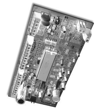
4 Button Programming...27 Remote Control Assignment (Liberator Only)...28 Remote Control Assignment (1755, 1755EX, 1758 and 1758EX Panels Only)...28 Reprogram ALL Modules...28 Paradox Memory Key...28 USER OPERATION Trouble Display...29 Partitioning...30 Programming Access Codes...30 Disarming & Deactivating an Alarm...31 Regular Arming...31 Stay Arming...31 Instant Arming...32 Force Arming...32 Manual Bypass Programming...32 Bypass Recall Feature...33 One-Touch Arming...33 Keyswitch Arming...33 Panic Alarms...33 Auto-Arming...34 Alarm Memory Display...34 Programming Chime Zones...34 Keypad Muting...34 Quick Function Keys...34 HARDWARE CONNECTIONS Single Zone Inputs...35 Double Zone Inputs (with ATZ option only)...35 Connecting a Keyswitch...36 Connecting Fire Circuits...36 PGM Connections...36 Connecting A Liberator Wireless Bus Module (SPC-319)...37 Connecting A Zone Expansion Module (SPC-ZX8)...37 Spectra 1725, 1725EX, 1728 and 1728EX PCB Layout...38 Spectra 1755, 1755EX, 1758 and 1758EX PCB Layout...39 Connecting Speakers to the Bell Output (Siren Driver Option Only) Programming Guide
5 Spectra Series 3
6 HOW DO I PROGRAM THE SYSTEM? The Spectra TM series control panels can be programmed using the WinLoad Software or by using any keypad connected to the Spectra control panel. For information on the WinLoad Software, please refer to the Spectra Installation & Reference Manual. To program the Spectra control panel using a keypad, you must enter the Programming Mode as shown below. Once a control panel has been programmed, you can use the Paradox Memory Key to copy the contents from the programmed control panel to one or more control panels (see page5). Default Installer Code: (see section [281] on page20) Default System Master Code: (see section [301] on page 21) To enter Programming Mode: STEP 1: Press [ENTER] STEP 2: Enter your [INSTALLER CODE] STEP 3: Enter 3 digits of [SECTION] you wish to program STEP 4: Enter required [DATA] SINGLE DIGIT DATA ENTRY METHOD (Hexadecimal and Decimal) Single Digit Data Entry is used in all sections except those specified in Multiple Feature Select Programming Method. After entering the programming mode as described in the shaded box above, some sections will require that you enter Decimal values from 000 to 255. Other sections will require that you enter Hexadecimal values from 0 to F. The required data will be clearly indicated in this manual. When entering the final digit in a section, the control panel will automatically save and advance to the next section. With the exception of sections 001 to 016, where after entering the first two digits, the control panel will switch to Multiple Feature Select Programming. Value or Action Table 1: Decimal and Hexadecimal Programming Table What Do I Press? What Do I See? 10-Zone LED 16-Zone LED LCD Values 1 to 9 [1] to [9] [1] to [9] [1] to [9] [1] to [9] A (hexa only) [0] [0 (10)] [10] A B (hexa only) [STAY] [STAY] [11] B C (hexa only) [BYP] [BYP] [12] C D (hexa only) [MEM] [MEM] [13] D E (hexa only) [TBL] / [TRBL] [TBL] [14] E F (hexa only) [PG] / [FNC1] [PG] [15] F Erase Current Digit [FORCE] Displays next digit or next section Exit Without Saving [CLEAR] [ENTER] flashes [ARM1] & [STAY1] flash SECTION [ ] Save Data (hexa only) [ENTER] Advances to the next section MULTIPLE FEATURE SELECT PROGRAMMING METHOD Sections: [001] to [016], [127] to [138], [302] to [348], [610], [650] to [651] After entering the programming mode as described in the shaded box above, each option from [1] to [8] will represent a specific feature or option. Press the key corresponding to the desired option and the corresponding light will illuminate or the option number will appear in the LCD display. This means the option is on. Press the key again to extinguish the corresponding light or remove the digit from the LCD display, thereby, turning off the option. Please note that pressing the [FORCE] key will set all 8 options to off. Press the keys as many times as you need until all 8 options in the current section are set. When the options are set, press the [ENTER] key to save and advance to the next section. 4 Programming Guide
7 DATA DISPLAY MODE (LED Keypads Only) In the Data Display Mode you can view the programmed contents of each section one digit at a time. After entering the desired 3-digit section (see step 3 of the To Enter Programming Mode box on the previous page), press the [ENTER] key to access the Data Display Mode. This mode will not function with sections using the Multiple Feature Select Programming Method (see previous page). PARADOX MEMORY KEY Copy the programmed contents of one Spectra control panel into the Paradox Memory Key. Then copy the contents of the Paradox Memory Key into as many Spectra control panels as you need. Each control panel is programmed in less than 3 seconds. If you use the Memory Key to download to a Spectra 1755, 1755EX, 1758, or 1758EX, you will have to reassign the remote controls (see page 28). Download to DESTINATION Control Panel 1)Remove AC and battery power from the control panel. 2)Insert the Memory Key onto the serial connector labeled KEY on the Spectra control panel to which you wish to download the contents of the memory key to. 3) Reapply AC and battery power. 4)Enter installer programming mode, enter section [900], then press [ENTER] to acknowledge. 5)When the keypad emits a confirmation beep, remove the Memory Key. Copy to Memory Key from SOURCE Control Panel 1)Remove AC and battery power from the control panel. 2)Insert Memory Key onto the serial connector labeled KEY on the Spectra control panel from which you wish to copy. Make sure the write protect jumper of the Memory Key is on. 3)Reapply AC and battery power. 4)Enter installer programming mode, enter section [902], then press [ENTER] to acknowledge. 5)When the keypad emits a confirmation beep, remove the Memory Key. Remove the Memory Key s jumper if you do not wish to accidentally overwrite its contents. Spectra Series 5
8 ZONE PROGRAMMING When programming zones please note that the Spectra control panels zone assignment is dependent on where the detection devices in the system are connected (see Table 2 below). Device connected to which input? Table 2: Zone Recognition Table 1725EX EX EX EX 1758 NO ATZ WITH ATZ NO ATZ WITH ATZ Control Panel Input 1 = Zone 1 Zone 1 & 4 Zone 1 Zone 1 & 6 Control Panel Input 2 = Zone 2 Zone 2 & 5 Zone 2 Zone 2 & 7 Control Panel Input 3 = Zone 3 Zone 3 & 6 Zone 3 Zone 3 & 8 Control Panel Input 4 = N/A N/A Zone 4 Zone 4 & 9 Control Panel Input 5 = N/A N/A Zone 5 Zone 5 & 10 Keypad Zone 1 = Zone 4 Zone 7 Zone 6 Zone 11 Keypad Zone 2 = Zone 5 Zone 8 Zone 7 Zone 12 Expansion Input 1 = Zone 6 Zone 9 Zone 8 Zone 13 Expansion Input 2 = Zone 7 Zone 10 Zone 9 Zone 14 Expansion Input 3 = Zone 8 Zone 11 Zone 10 Zone 15 Expansion Input 4 = Zone 9 Zone 12 Zone 11 Zone 16 Expansion Input 5 = Zone 10 Zone 13 Zone 12 N/A Expansion Input 6 = Zone 11 Zone 14 Zone 13 N/A Expansion Input 7 = Zone 12 Zone 15 Zone 14 N/A Expansion Input 8 = Zone 13 Zone 16 Zone 15 N/A WHAT IS AN EXPANSION INPUT? There are a total of eight expansion inputs available. Each hardwired input on a Zone Expansion Module or wireless transmitter used by the Liberator TM Wireless Bus Module can be assigned to an expansion input. The expansion inputs can be used in any combination. For example, you can assign four wireless transmitters as well as 4 hardwire inputs to the expansion inputs. Regardless of how many expansion modules are being used, the control panel cannot support more than eight expansion inputs. The expansion module inputs are assigned as follows: SPC-319 Liberator Wireless Bus Module Wireless transmitters assigned to sections [601] to [608] of the control panel represent expansion inputs 1 to 8 respectively. Refer to Wireless Transmitter Assignment on page22. SPC-ZX4 and SPC-ZX8 Zone Expansion Module Detection devices connected to input terminals Z1 to Z4 of the SPC-ZX4 module or Z1 to Z8 of the SPC-ZX8 module, represent expansion inputs 1 to 8 respectively. Please note that the module s inputs must be enabled in section [651] of the control panel. Refer to Zone Assignment on page 25. Do not assign devices from different modules to the same expansion input. For example, do not assign a wireless transmitter to section [601], then connect a detection device to input Z1 of the SPC-ZX8 and enable option [1] in section [651]. 6 Programming Guide
9 HOW DO I PROGRAM THE ZONES? STEP 1: Press the [ENTER] key STEP 2: Enter the [INSTALLER CODE] (Default: ) STEP 3: Enter 3-digit [SECTION] STEP 4: Enter one digit from the Zone Definition table STEP 5: Enter one digit from the Partition Assignment table STEP 6: Select one or more options from the Zone Options table STEP 7: Press the [ENTER] key Section # Description Zone Definition Partition Assignment Zone Options First Digit Second Digit Feature Select [001]= Zone 1: [002]= Zone 2: [003] = Zone 3: [004] = Zone 4: [005] = Zone 5: [006] = Zone 6: [007] = Zone 7: [008] = Zone 8: [009] = Zone 9: [010] = Zone 10: [011] = Zone 11: [012] = Zone 12: [013] = Zone 13: [014] = Zone 14: [015] = Zone 15: [016] = Zone 16: Default = Empty Default = 1 Default = 1 & 2 on Spectra Series 7
10 SYSTEM TIMERS Section # Decimal Value ( ) Description Default Value [050] / / x10 msec. ZONE SPEED (ZONE 1) 600 msec. [051] / / x10 msec. ZONE SPEED (ZONE 2) 600 msec. [052] / / x10 msec. ZONE SPEED (ZONE 3) 600 msec. [053] / / x10 msec. ZONE SPEED (ZONE 4) 600 msec. [054] / / x10 msec. ZONE SPEED (ZONE 5) 600 msec. [055] / / X10 msec. ZONE SPEED (ZONE 6) 600 msec. [056] / / X10 msec. ZONE SPEED (ZONE 7) 600 msec. [057] / / X10 msec. ZONE SPEED (ZONE 8) 600 msec. [058] / / X10 msec. ZONE SPEED (ZONE 9) 600 msec. [059] / / x10 msec. ZONE SPEED (ZONE 10) 600 msec. [060] / / x10 msec. ZONE SPEED (ZONE 11) 600 msec. [061] / / x10 msec. ZONE SPEED (ZONE 12) 600 msec. [062] / / x10 msec. ZONE SPEED (ZONE 13) 600 msec. [063] / / x10 msec. ZONE SPEED (ZONE 14) 600 msec. [064] / / x10 msec. ZONE SPEED (ZONE 15) 600 msec. [065] / / x10 msec. ZONE SPEED (ZONE 16) 600 msec. NOTE: If ATZ is enabled (section [132], key [5]), do not set the Zone Speed to less than 50msec. as this may cause false alarms. [066] / / seconds (000 = follow stop event) PGM1 TIMER 5 sec. [067] / / seconds (000 = follow stop event) PGM2 TIMER (1755/EX & 1758/EX ONLY) 5 sec. [068] / / seconds (000 = follow stop event) GLOBAL PGM TIMER (SEE PAGE 23 & 26) 5 sec. [069] / / seconds ENTRY DELAY 1 45 sec. [070] / / seconds ENTRY DELAY 2 45 sec. [071] / / seconds EXIT DELAY 1 30 sec. [072] / / seconds EXIT DELAY 2 30 sec. [073] / / minutes (000 = no bell on alarm) BELL CUT-OFF TIME - PARTITION 1 4 min. [074] / / minutes (000 = no bell on alarm) BELL CUT-OFF TIME - PARTITION 2 4 min. [075] / / x15 minutes (000 = disabled) NO MOVEMENT TIME - PARTITION 1 Disabled [076] / / x15 minutes (000 = disabled) NO MOVEMENT TIME - PARTITION 2 Disabled [077] / / seconds (min.= 10 sec.) ANS. MACHINE OVERRIDE DELAY Disabled [078] / / (000 = no answer; max. = 15 rings) NUMBER OF RINGS 8 rings [079] / / x2 sec. (min.= 32 sec.) TLM FAIL TIMER 32 sec. [080] / / seconds DELAY ALARM TRANSMISSION Disabled [081] / / (000 = 16; max. 16) MAXIMUM DIALING ATTEMPTS 8 attempts [082] / / seconds DELAY BETWEEN ATTEMPTS 20 sec. [083] / / seconds PAGER DELAY 5 sec. [084] / / seconds (min. 10 sec.) INTELLIZONE DELAY 48 sec. [085] / / seconds RECENT CLOSING DELAY No delay [086] / / minutes POWER FAILURE REPORT DELAY 15 min. [087] / / days (000 = disabled) AUTO TEST REPORT Disabled [088] / / ( = +1 to +127 sec.) CLOCK ADJUST Disabled ( = -1 to -127 sec.) [089] / / (000 = Disabled; max. = 15) AUTO ZONE SHUTDOWN COUNTER 5 [090] / / minutes (000 = disabled) RECYCLE ALARM DELAY Disabled [091] / / (000 = disabled) RECYCLE ALARM COUNTER Disabled [110] / : / Hrs (00-23) & Min. (00-59) AUTO TEST REPORT (TIME OF DAY) Disabled [111] / : / Hrs (00-23) & Min. (00-59) AUTO-ARM TIME - PARTITION 1 Disabled [112] / : / Hrs (00-23) & Min. (00-59) AUTO-ARM TIME - PARTITION 2 Disabled 8 Programming Guide
11 HOW DO I SET THE PROGRAMMABLE OUTPUTS? Example: section [120] = : this means PGM1 will activate whenever partition 2 is Stay Armed. Section # Event Group # Sub-Group # Partition # [120] = PGM1 Start Event / / / [121] = PGM1 Stop Event / / / Can be used as another Start Event if section [066] is programmed with a value other than 000. [122] = PGM2 Start Event / / / [123] = PGM2 Stop Event / / / Can be used as another Start Event if section [067] is programmed with a value other than = Partition 1 02 = Partition 2 99 = Any Partition Sub-Groups proceeded by (Partition 1 only) cannot be assigned to activate in partition 2. [124] = Global PGM Start Event / / / [125] = Global PGM Stop Event / / / Used to activate PGMs on expansion modules and LCD keypads (see page 22 and page25) Event Group # Sub-Group # 00 = Zone OK = Zones 1 to = Any Zone 01 = Zone Open = Zones 1 to = Any Zone 02 = Partition Status 00 = System not ready (Partition 1 only) 01 = System ready (Partition 1 only) 02 = Steady Alarm in Partition 03 = Pulsed Alarm in Partition 04 = Pulsed or Steady Alarm in Partition 05 = Alarm in Partition Restored 06 = Bell Squawk Activated (Partition 1 only) 07 = Bell Squawk Deactivated (Partition 1 only) 99 = Any Sub-Group 03 = Global Disarm with User Code = User Code Numbers 001 to = Any User Code 04 = Special Global Disarm 00 = Disarm with WinLoad Software 01 = Disarm with Keyswitch 99 = Any Sub-Group 05 = Non-Reportable Events 00 = Telephone Line Trouble (Partition 1 only) 01 = [PG] or [FNC1] key was pressed (Partition 1 only) 02 = Instant Arming 03 = Stay Arming 04 = Force Arming 05 = Fast Exit (Force & Regular Only) 06 = PC Fail to Communicate (Partition 1 only) 07 = Midnight (Partition 1 only) 08 = Ground start (Partition 1 only) 99 = Any Sub-Group (Partition 1 only, except 02 to 05) Spectra Series 9
12 Event Group # Sub-Group # 06 = Arm/Disarm with Remote Control = Remote Controls 1 to 8 99 = Any Remote Control 07 = Button Pressed on Remote (see button option B on page 27) 08 = Button Pressed on Remote (see button option C on page27) 09 = Button Pressed on Remote (see button option D on page27) = Remote Controls 1 to 8 99 = Any Remote Control = Remote Controls 1 to 8 99 = Any Remote Control = Remote Controls 1 to 8 99 = Any Remote Control 10 = Bypass Programming = User Code Numbers 001 to = Any User Code 11 = User Activated PGM = User Code Numbers 001 to = Any User Code 12 = Zone with Delay Transmission Option Enabled is Breached = Zones 1 to = Any Zone 13 = Arm with User Code = User Code Numbers 001 to = Any User Code 14 = Special Arm 00 = Auto Arming (timed/no movement) 01 = Late to Close (auto arming failed) 02 = No Movement Auto Arming 03 = Partial Arming (stay, force, instant, bypass) 04 = One-Touch Arming 05 = Arm with WinLoad Software 06 = Arm with Keyswitch 99 = Any Sub-Group 15 = Disarm with User Code = User Code Numbers 001 to = Any User Code 16 = Disarm After Alarm w/ User Code = User Code Numbers 001 to = Any User Code 17 = Cancel Alarm with User Code = User Code Numbers 001 to = Any User Code 18 = Special Disarm 00 = Cancel Auto Arm (timed/no movement) 01 = Disarm with WinLoad Software 02 = Disarm with Keyswitch 03 = Reserved for Future Use 04 = Disarm after alarm with WinLoad Software 05 = Disarm after alarm with Keyswitch 06 = Cancel Alarm with WinLoad Software 07 = Cancel Alarm with Keyswitch 99 = Any Sub-Group 19 = Zone Bypassed on Arming = Zones 1 to = Any Zone 20 = Zone in Alarm = Zones 1 to = Any Zone 21 = Fire Alarm 03 = Zone 3 99 = Any Zone 22 = Zone Alarm Restore = Zones 1 to = Any Zone 23 = Fire Alarm Restore 03 = Zone 3 99 = Any Zone 10 Programming Guide
13 Event Group # Sub-Group # 24 = Special Alarm 00 = Emergency Panic 01 = Auxiliary Panic 02 = Fire Panic 03 = Recent Closing 04 = Auto Zone Shutdown 05 = Duress Alarm 99 = Any Sub-Group 25 = Auto Zone Shutdown = Zones 1 to = Any Zone 26 = Zone Tamper = Zones 1 to = Any Zone 27 = Zone Tamper Restore = Zones 1 to = Any Zone 28 = System Trouble 01 = AC Loss: only after Power Failure Delay has elapsed (Partition 1 only) 02 = Battery Failure (Partition 1 only) 03 = Auxiliary current overload (Partition 1 only) 04 = Bell current overload (Partition 1 only) 05 = Bell disconnected (Partition 1 only) 06 = Timer Loss (Partition 1 only) 07 = Fire Loop Trouble (Partition 1 only) 08 = Wireless Transmitter Low Battery (Partition 1 only) 09 = Module Fault (Partition 1 only) 10 = Printer Fault (Partition 1 only) 11 = Fail to Communicate (Partition 1 only) 99 = Any Sub-Group (Partition 1 only) 29 = System Trouble Restore 00 = TLM restore (Partition 1 only) 01 = AC Loss restore (Partition 1 only) 02 = Battery Failure restore (Partition 1 only) 03 = Auxiliary current overload restore (Partition 1 only) 04 = Bell current overload restore (Partition 1 only) 05 = Bell disconnected restore (Partition 1 only) 06 = Timer Programmed (Partition 1 only) 07 = Fire Loop Trouble restore (Partition 1 only) 08 = Wireless Transmitter Low Battery restore (Partition 1 only) 09 = Module Fault restore (Partition 1 only) 10 = Printer Fault restore (Partition 1 only) 11 = Fail to Communicate restore (Partition 1 only) 99 = Any Trouble Restore (Partition 1 only) 30 = Special Reporting 00 = System Power Up (Partition 1 only) 01 = Test Report (Partition 1 only) 02 = WinLoad Software Access (Partition 1 only) 03 = WinLoad Software Access finish (Partition 1 only) 04 = Installer enters programming mode (Partition 1 only) 05 = Installer exits programming mode (Partition 1 only) 99 = Any Sub-Group (Partition 1 only) 31 = Wireless Transmitter Supervision Loss 32 = Wireless Transmitter Supervision Loss Restore = Zones 1 to = Any Zone = Zones 1 to = Any Zone Spectra Series 11
14 SECTION [127]: General Options SYSTEM OPTIONS Bold = Default Setting Option OFF ON [1] Partitioning Disabled Enabled [2] Access Code Length 6-digits 4-digits [3] Keypad Audible Trouble Warning Disabled Enabled [4] Lock System Master Code Disabled Enabled [5] Battery Charge Current 350mA 700mA [6] User Code 048 is a Duress Code Disabled Enabled [7] Alarm Relay follows (1755/EX & 1758/EX only) Bell Output Global PGM [8] Normal State of PGM1 Normally Closed (N.C.) Normally Open SECTION [128]: General Options Option OFF ON [1] Panic 1: Keys [1] & [3] Disabled Enabled [2] Panic 2: Keys [4] & [6] Disabled Enabled [3] Panic 3: Keys [7] & [9] Disabled Enabled [4] Panic 1: Silent or Audible Silent Audible [5] Panic 2: Silent or Audible Silent Audible [6] Panic 3: Silent or Fire Silent Fire [7] Keypad 1 Tamper Supervision Disabled Enabled [8] Keypad 2 Tamper Supervision Disabled Enabled SECTION [129]: General Options Option OFF ON [1] PGM2 Output Activation Option* Steady Pulse (flash) [2] PGM2 Pulse Once Every 30sec. If System Armed* Disabled Enabled [3] PGM2 Pulse On Arm, Twice On Disarm* Disabled Enabled [4] SPC-ZX4/8 Zone Expansion Module Supervision Disabled Enabled [5] SPC-319 Wireless Module Supervision Disabled Enabled [6] SPC-319 Wireless Module Low Battery Super. Disabled Enabled [7] Siren Driver* on Bell Output Disabled Enabled [8] Normal State of PGM2 Normally Closed (N.C.) Normally Open *1755, 1755EX, 1758 and 1758EX only SECTION [130]: Arming/Disarming Options Option OFF ON [1] One-Touch Regular Arming Disabled Enabled [2] One-Touch Stay Arming Disabled Enabled [3] One-Touch Force Arming Disabled Enabled [4] One-Touch Bypass Programming Disabled Enabled [5] Restrict Arming on Battery Failure Disabled Enabled [6] Restrict Arming on Tamper Trouble Disabled Enabled [7] Bell Squawk on Arm/Disarm with Keypad Disabled Enabled [8] Beep on Exit Delay Disabled Enabled 12 Programming Guide
15 SECTION [131]: Arming/Disarming Options Bold = Default Setting Option OFF ON [1] Report Disarming Always Only after alarm [2] Regular Arming Switches to Force Arming Disabled Enabled [3] Bell Squawk on Arm/Disarm with Remote Control Disabled Enabled (must be enabled for UL installations) [4] No Exit Delay When Arming with a Remote Control Disabled Enabled [5] No Exit Delay Beeps and No Bell Squawk When Disabled Enabled Stay Arming [6] Restrict Arming On Wireless Transmitter Disabled Enabled Supervision Loss [7] Generate Supervision Loss if Detected on Yes No Bypassed Wireless Zone [8] Normal State of Global PGM Normally Closed (N.C.) Normally Open SECTION [132]: Zone Options Option OFF ON [1]&[2] see table see table see table see table [3] Generate Tamper if detected on Bypassed Zone Yes No [4] EOL (end-of-line) Resistors No EOL Use EOL Resistors [5] ATZ Zone Doubling (optional) Disabled Enabled [6] Report Zone Restore On Bell Cut-off On Zone Closure [7]&[8] see table see table see table see table SECTION [133]: Partition 1 Options Option OFF ON [1] Auto-Arm on Time Disabled Enabled [2] Auto-Arm on No Movement Disabled Enabled [3] Auto Arming = Regular or Stay Regular Arming Stay Arming [4] Future Use N/A N/A [5] Future Use N/A N/A [6] Future Use N/A N/A [7] Switch to Stay Arming if no entry delay is opened Disabled Enabled [8] Future Use N/A N/A Spectra Series 13
16 SECTION [134]: Partition 2 Options Bold = Default Setting Option OFF ON [1] Auto-Arm on Time Disabled Enabled [2] Auto-Arm on No Movement Disabled Enabled [3] Auto Arming = Regular or Stay Regular Arming Stay Arming [4] Future Use N/A N/A [5] Future Use N/A N/A [6] Future Use N/A N/A [7] Switch to Stay Arming if no entry delay is opened Disabled Enabled [8] Future Use N/A N/A SECTION [135]: Dialer Options Option OFF ON [1] [2] see table see table see table see table [3] Reporting Disabled Enabled [4] Dialing Method Pulse Dialing Tone (DTMF) Dialing [5] Pulse Ratio 1:2 (Europe) 1:1.5 (North America) [6] If armed, activate bell output on Com. Failure Disabled Enabled [7] Future Use N/A N/A [8] Future Use N/A N/A SECTION [136]: Dialer Options Option OFF ON [1] Call Back Disabled Enabled [2] Automatic Event Buffer Transmission Disabled Enabled [3] Contact I.D. Report Codes Programmable All Codes (automatic) [4] Alternate Dial Disabled Enabled [5] If no dial tone is present Continue after 4 sec. Hang-up after 16 sec. [6] Future Use N/A N/A [7] Future Use N/A N/A [8] Future Use N/A N/A SECTION [137]: Event Call Direction Option OFF ON [1] Call Telephone #1 for Arming/Disarming Report Codes Disabled Enabled [2] Call Telephone #2 for Arming/Disarming Report Codes Disabled Enabled [3] Call Telephone #1 for Alarm/Restore Report Codes Disabled Enabled [4] Call Telephone #2 for Alarm/Restore Report Codes Disabled Enabled [5] Call Telephone #1 for Tamper/Restore Report Codes Disabled Enabled [6] Call Telephone #2 for Tamper/Restore Report Codes Disabled Enabled [7] Future Use N/A N/A [8] Future Use N/A N/A 14 Programming Guide
17 SECTION [138]: Event Call Direction Option OFF ON [1] Call Telephone #1 for Trouble/Restore Report Codes Disabled Enabled [2] Call Telephone #2 for Trouble/Restore Report Codes Disabled Enabled [3] Call Telephone #1 for Special Report Codes Disabled Enabled [4] Call Telephone #2 for Special Report Codes Disabled Enabled [5] Future Use N/A N/A [6] Future Use N/A N/A [7] Future Use N/A N/A [8] Future Use N/A N/A Bold = Default Setting COMMUNICATION SETTINGS Section # [140] / REPORTING FORMATS TEL1 TEL2 1 = ADEMCO SLOW (1400HZ, 1900HZ, 10BPS) 2 = SILENT KNIGHT FAST (1400HZ, 1900HZ, 20BPS) 3 = SESCOA (2300HZ, 1800HZ, 20BPS) 4 = ADEMCO EXPRESS (DTMF 4+2) 5 = ADEMCO CONTACT ID (DEFAULT) ALSO, SEE OPTION [3] IN SECTION [136] 6 = PAGER FORMAT [141] / / / PANEL IDENTIFIER (WINLOAD SOFTWARE) [142] / / / PC PASSWORD (WINLOAD SOFTWARE) IMPORTANT NOTE: To enter account numbers with less than four digits, use the [FORCE] key to enter blank digits. [143] / / / PARTITION ACCOUNT NUMBER 1 [144] / / / PARTITION ACCOUNT NUMBER 2 [150] / / / / / / / / / / / / / / / / / / / / / / / / / / / / / / / PC TELEPHONE NUMBER FOR WINLOAD SOFTWARE (32-DIGITS, if less than 32 press [ENTER] to accept) [151] / / / / / / / / / / / / / / / / / / / / / / / / / / / / / / / CENTRAL STATION TELEPHONE OR PAGER NUMBER 1 (32-DIGITS, if less than 32 press [ENTER] to accept) [152] / / / / / / / / / / / / / / / / / / / / / / / / / / / / / / / CENTRAL STATION TELEPHONE OR PAGER NUMBER 2 (32-DIGITS, if less than 32 press [ENTER] to accept) [153] / / / / / / / / / / / / / / / / / / / / / / / / / / / / / / / BACK UP TELEPHONE NUMBER (32-DIGITS, if less than 32 press [ENTER] to accept) Special Keys for Telephone Numbers [STAY] = * [MEM] = Switch from pulse to tone dialing or vice versa [FORCE] = Delete current digit [BYP] = # [TBL] or [TRBL] = 4-second pause [PG] or [FNC1] = Inserts Blank Space Spectra Series 15
18 REPORT CODES Each section contains report codes for up to 4 events: Ademco Slow, Silent Knight, SESCOA, Ademco Express and Pager Formats: Enter desired 1 or 2-digit hexa-value (0-F) Ademco All Codes Format: The control panel automatically generates report codes from the All Codes - Ademco Report Code List on page19. Ademco Programmable Format: Enter desired 2-digit hexa values from the Programmable - Ademco Report Code List on page 18. Also Note that entering FF will set the report code to the default Ademco Report Code. ARMING REPORT CODES [160]: / Access code 1 / Access code 2 / Access code 3 / Access code 4 [161]: / Access code 5 / Access code 6 / Access code 7 / Access code 8 [162]: / Access code 9 / Access code 10 / Access code 11 / Access code 12 [163]: / Access code 13 / Access code 14 / Access code 15 / Access code 16 [164]: / Access code 17 / Access code 18 / Access code 19 / Access code 20 [165]: / Access code 21 / Access code 22 / Access code 23 / Access code 24 [166]: / Access code 25 / Access code 26 / Access code 27 / Access code 28 [167]: / Access code 29 / Access code 30 / Access code 31 / Access code 32 [168]: / Access code 33 / Access code 34 / Access code 35 / Access code 36 [169]: / Access code 37 / Access code 38 / Access code 39 / Access code 40 [170]: / Access code 41 / Access code 42 / Access code 43 / Access code 44 [171]: / Access code 45 / Access code 46 / Access code 47 / Access code 48 SPECIAL ARMING CODES [172]: / Auto-Arming / Late to close / No Movement / Partial Arming [173]: / Quick Arming / Arming via PC / Keyswitch Arming / N/A DISARMING REPORT CODES [174]: / Access code 1 / Access code 2 / Access code 3 / Access code 4 [179]: / Access code 21 / Access code 22 / Access code 23 / Access code 24 [184]: / Access code 41 / Access code 42 / Access code 43 / Access code 44 [175]: / Access code 5 / Access code 6 / Access code 7 / Access code 8 [176]: / Access code 9 / Access code 10 / Access code 11 / Access code 12 [177]: / Access code 13 / Access code 14 / Access code 15 / Access code 16 [178]: / Access code 17 / Access code 18 / Access code 19 / Access code Programming Guide [180]: / Access code 25 / Access code 26 / Access code 27 / Access code 28 [181]: / Access code 29 / Access code 30 / Access code 31 / Access code 32 [182]: / Access code 33 / Access code 34 / Access code 35 / Access code 36 [183]: / Access code 37 / Access code 38 / Access code 39 / Access code 40 [185]: / Access code 45 / Access code 46 / Access code 47 / Access code 48 SPECIAL DISARMING CODES [186]: / Cancel Auto-Arm / Disarming via PC / Keyswitch Disarm / N/A
19 ALARM REPORT CODES ALARM [187]: / Zone 1 / Zone 2 / Zone 3 / Zone 4 [188]: / Zone 5 / Zone 6 / Zone 7 / Zone 8 [189]: / Zone 9 / Zone 10 / Zone 11 / Zone 12 [190]: / Zone 13 / Zone 14 / Zone 15 / Zone 16 TAMPER REPORT CODES TROUBLE [197]: / Zone 1 / Zone 2 / Zone 3 / Zone 4 [198]: / Zone 5 / Zone 6 / Zone 7 / Zone 8 [199]: / Zone 9 / Zone 10 / Zone 11 / Zone 12 RESTORE [191]: / Zone 1 / Zone 2 / Zone 3 / Zone 4 [192]: / Zone 5 / Zone 6 / Zone 7 / Zone 8 [193]: / Zone 9 / Zone 10 / Zone 11 / Zone 12 [194]: / Zone 13 / Zone 14 / Zone 15 / Zone 16 [200]: / Zone 13 / Zone 14 / Zone 15 / Zone 16 RESTORE [201]: / Zone 1 / Zone 2 / Zone 3 / Zone 4 [202]: / Zone 5 / Zone 6 / Zone 7 / Zone 8 SPECIAL [195]: / Emergency Panic / Auxiliary Panic / Fire Panic / Recent Closing [196]: / Zone Shutdown / Duress / N/A / N/A [203]: / Zone 9 / Zone 10 / Zone 11 / Zone 12 [204]: / Zone 13 / Zone 14 / Zone 15 / Zone 16 SYSTEM TROUBLE REPORT CODES SYSTEM TROUBLE [205]: / N/A / AC Failure / Battery Failure / Auxiliary Supply RESTORE [208]: / TLM / AC Failure / Battery Failure / Auxiliary Supply SPECIAL [211]: / Cold Start (Shutdown) / Test Report / PC Call Back / PC Access [206]: / Bell Output Overload / Bell Output Disconnect / Timer Loss / Fire Loop Trbl [207]: / Wireless Low Battery / Module Fault / Printer Fault / Fail to Communicate [209]: / Bell Output Overload / Bell Output Disconnect / Timer Programmed / Fire Loop Trbl [210]: / Wireless Low Battery / Module Fault / Printer Fault / N/A [212]: / Installer In / Installer Out / N/A / N/A [213]: / TX Supervision Loss / TX Supervision Restore / N/A / N/A Spectra Series 17
20 PROGRAMMABLE - ADEMCO CONTACT ID REPORT CODE LIST If using the Ademco Contact ID Programmable code format, enter the 2-digit hexadecimal value from the table below (Prog. Value) into sections [160] to [213] to program the desired report codes. To enter a 0 value press the [FORCE] key. CID# Reporting Prog. Code Value CID# Reporting Prog. Code Value CID# Reporting Prog. Code Value MEDICAL ALARMS Low Water Level 2F 403 Automatic O/C 5D 100 Medical Alarm Pump Activated Late to O/C 5E 101 Pendant Transmitter Pump Failure Deferred 5F 102 Fail to Report In 03 SYSTEM TROUBLES & Cancel 60 FIRE ALARMS System Trouble Remote Arm/Disarm Fire Alarm AC Loss Quick Arm Smoke Low System Battery Keyswitch O/C Combustion RAM Checksum Bad 35 REMOTE ACCESS Water Flow ROM Checksum Bad Callback Request Made Heat System Reset Success - Download Access Pull Station Panel Program Changed Unsuccessful Access Duct 0A 307 Self-Test Failure System Shutdown Flame 0B 308 System Shutdown 3A 415 Dialer Shutdown Near Alarm 0C 309 Battery Test Failure 3B ACCESS CONTROL PANIC ALARMS Ground Fault 3C 421 Access Denied Panic Alarm 0D SOUNDER/RELAY TROUBLES Access Report By User 6A 121 Duress 0E 320 Sounder Relay 3D SYSTEM DISABLES & Silent 0F 321 Bell 1 3E SOUNDER RELAY DISABLES Audible Bell 2 3F 520 Sounder/Relay Disabled 6B BURGLAR ALARMS Alarm Relay Bell 1 Disable 6C 130 Burglary Trouble Relay Bell 2 Disable 6D 131 Perimeter Reversing Alarm Relay Disable 6E 132 Interior 13 SYSTEM PERIPHERAL TROUBLES & Trouble Relay Disable 6F Hour System Peripheral Reversing Relay Disable Entry/Exit Polling Loop Open 44 SYSTEM PERIPHERAL DISABLES & Day/Night Polling Loop Short 45 COMMUNICATION DISABLES & Outdoor Exp. Module Failure Dialer Disabled Tamper Repeater Failure Radio xmitter Disabled Near Alarm Local Printer Paper Out 48 BYPASSES GENERAL ALARMS Local Printer Failure Zone Bypass General Alarm 1A COMMUNICATION TROUBLES & Fire Bypass Polling Loop Open 1B 350 Communication 4A Hour Zone Bypass Polling Loop Short 1C 351 Telco Fault 1 4B 573 Burg. Bypass Expansion Module Failure 1D 352 Telco Fault 2 4C 574 Group Bypass Sensor Tamper 1E 353 Long Range Radio 4D TEST/MISC Expansion Module Tamper 1F 354 Fail to Communicate 4E 601 Manual Trigger Test HOUR NON-BURGLARY & Loss of Radio Supervision 4F 602 Periodic Test Report Hour Non-Burglary Loss of Central Polling Periodic RF Xmission 7A 151 Gas Detected 21 PROTECTION LOOP TROUBLES Fire Test 7B 152 Refrigeration Protection Loop Status Report to Follow 7C 153 Loss of Heat Protection Loop Open Listen-in to Follow 7D 154 Water Leakage Protection Loop short Walk Test Mode 7E 155 Foil Break Fire Trouble Event Log Reset 7F 156 Day Trouble 26 SENSOR TROUBLES Event Log 50% Full Low Bottled Gas Level Sensor Trouble Event Log 90% Full High Temp Loss of Super. -RF Event Log Overflow Low Temp Loss of Super. - RPM Time/Date Reset Loss of Air Flow 2A 383 Sensor Tamper Time/Date Inaccurate 84 FIRE SUPERVISORY & RF xmtr. Low Battery Program Mode Entry Fire Supervisory 2B OPEN/CLOSE Program Mode Exit Low Water Pressure 2C 400 Open/Close 5A 631 Exception Schedule Change Low CO2 2D 401 O/C by User 5B 203 Gate Valve Sensor 2E 402 Group O/C 5C 18 Programming Guide
21 ALL CODES - ADEMCO CONTACT ID REPORT CODE LIST System Event Arming with Master Code (##) Arming with User Code (##) Arming with Keyswitch (##) Auto Arming Arm with PC software Late To Close No Movement Partial arming Quick arming Default Contact ID Report Code when option [3] is on in section [136] 3 4A1 - Close by user 3 4A1 - Close by user 3 4A9 - Keyswitch Close 3 4A3 - Automatic Close 3 4A7 - Remote arm/disarm 3 4A4 - Late to Close 3 4A4 - Late to Close Group bypass Quick arm Disarm with Master Code (##) Disarm with User Code (##) Disarm with Keyswitch (##) Disarm after alarm with Master Code (##) Disarm after alarm with User Code (##) Disarm after alarm with Keyswitch (##) 1 4A1 - Open by user 1 4A1 - Open by user 1 4A9 - Keyswitch Open 1 4A1 - Open by user 1 4A1 - Open by user 1 4A9 - Keyswitch Open Auto Arming Cancellation Disarm with PC software Disarm after an alarm with PC software 1 4A5 - Deferred Open/Close 1 4A7 - Remote arm/disarm 1 4A7 - Remote arm/disarm Zone Bypassed (##) Zone alarm (##) Fire alarm (##) Zone alarm restore (##) Fire alarm restore (##) 1 57A - Zone bypass 1 13A - Burglary Alarm 1 11A - Fire alarm 3 13A - Burglary Alarm Restore 3 11A - Fire alarm Restore Panic 1 - Emergency Panic 2 - Medical Panic 3 - Fire 1 12A - Panic alarm 1 1AA - Medical alarm Pull Station Recent closing Global zone shutdown Duress alarm Zone shutdown (##) 3 4AA - Open/Close Group bypass Duress 1 57A - Zone bypass Zone tampered (##) Zone tamper restore (##) Sensor tamper Sensor tamper restore AC Failure 1 3A1 - AC loss Battery Failure 1 3A9 - Battery test failure Auxiliary supply trouble 1 3AA - System trouble Bell output current limit Bell 1 Bell absent Bell 1 Spectra Series 19
22 System Event Clock lost Fire loop trouble Wireless Transmitter Low Battery Wireless Transmitter Supervision Loss Module fault Printer fault Fail to communicate with central station Default Contact ID Report Code when option [3] is on in section [136] Time/Date inaccurate Fire trouble RF xmtr. low battery Loss of super. - RF Expansion module failure Local printer failure Fail to communicate TLM trouble restore AC Failure restore Battery Failure restore Auxiliary supply trouble restore Bell output current limit restore Bell absent restore Clock programmed Fire loop trouble restore Wireless Transmitter Low Battery Wireless Transmitter Supervision Loss Module fault restore Printer fault restore Fail to communicate with central station Telco 1 fault restore 3 3A1 - AC loss restore 3 3A9 - Battery test restore 3 3AA - System trouble restore Bell 1 restore Bell 1 restore Time/Date Reset Fire trouble restore RF xmtr. low battery Loss of super. - RF Expansion module failure restore Local printer failure restore Fail to communicate restore Cold Start Test Report engaged PC software communication finished Installer on site Installer programming finished 1 3A8 - System shutdown 1 6A2 - Periodic test report Successful - download access Program mode Entry Program mode Exit SYSTEM SETTINGS Section # Description [280] / : / SYSTEM REAL TIME CLOCK (HH:MM) [281] / / / / / INSTALLER CODE Default: [282] / / INSTALLER CODE LOCK Default: 000 (147 to lock, 000 to unlock) IMPORTANT NOTE: If the Access Code Length is changed from four digits to six digits when access codes have already been programmed, the control panel will automatically add the last 2 digits by using the first 2 digits. For example, if the access code is 1234 and you switch to 6 digits, the code will become Be sure to verify the access codes after switching from 4-digit access codes to 6-digit codes. When switching from six digits to four digits, the control panel will simply remove the final two digits of the access code. For example, will become Programming Guide
23 USER CODE OPTIONS [301] / / / / / SYSTEM MASTER CODE (see note on preceeding page) Default: [1] on = Partition 1 Access [2] on = Partition 2 Access [3] on = Bypass Programming [4] on = Stay Arming off = Option Disabled [5] on = Force Arming [6] on = Arm Only [7] on = PGM Activation Only [8] on = Not Used Section # User Code Options (on/off) Default: [302] Master Code [303] Master Code [304] User Code [305] User Code [306] User Code [307] User Code [308] User Code [309] User Code [310] User Code [311] User Code [312] User Code [313] User Code [314] User Code [315] User Code [316] User Code [317] User Code [318] User Code [319] User Code [320] User Code [321] User Code [322] User Code [323] User Code [324] User Code Section # User Code Options (on/off) Default: [325] User Code [326] User Code [327] User Code [328] User Code [329] User Code [330] User Code [331] User Code [332] User Code [333] User Code [334] User Code [335] User Code [336] User Code [337] User Code [338] User Code [339] User Code [340] User Code [341] User Code [342] User Code [343] User Code [344] User Code [345] User Code [346] User Code [347] User Code [348] User Code Spectra Series 21
24 LIBERATOR WIRELESS BUS MODULE (SPC-319) The following options and features are only available to program when a Liberator Wireless Bus Module has been connected to the Spectra control panel s communication bus as shown on page 37. The Liberator Wireless Bus Module (SPC-319) allows you to add up to eight fully programmable remote controls and up to eight Liberator Wireless Detectors and Contact Switches (door contacts). The SPC-319 also provides one programmable 5A relay (PGM). A second 5A programmable relay (PGM) is available as an option. The Liberator Wireless Bus Module does not function with the Spectra 1755, 1755EX, 1758 and 1758EX control panels. Do not connect more than one Liberator Module. WIRELESS TRANSMITTER ASSIGNMENT (Liberator Only) The serial number can be located on the inside of the transmitter or you can use the Serial Number Display (see page23). Use the Liberator Wireless Motion Detectors (Model# 9002) and the Liberator Contact Switches (Model# 9020). Section # Serial # [601] / / / / / EXPANSION INPUT 1= [602] / / / / / EXPANSION INPUT 2= [603] / / / / / EXPANSION INPUT 3= [604] / / / / / EXPANSION INPUT 4= [605] / / / / / EXPANSION INPUT 5= [606] / / / / / EXPANSION INPUT 6= [607] / / / / / EXPANSION INPUT 7= [608] / / / / / EXPANSION INPUT 8= WARNING! Avoid assigning devices from different modules to the same Expansion Input. For example, do not assign a wireless transmitter to section [601], then connect a detection device to input 1 of a hardwire module and enable option [1] in section [651]. This would mean both devices have been assigned to the same Expansion Input. WIRELESS MODULE OPTIONS (Liberator Only) SECTION [610]: General Options Bold = Default Setting Option OFF ON [1] Wireless Transmitter Supervision Disabled Enabled [2] Supervision Timer Setting Low = Every 12 hours High = Every 12 minutes (must be same as the transmitter s jumper setting) [3] PGM1 on Liberator follows Global PGM Disabled Enabled programmed in sections [124] & [125] [4] PGM2 on Liberator follows Global PGM Disabled Enabled programmed in sections [124] & [125] [5] Future Use N/A N/A [6] Future Use N/A N/A [7] Future Use N/A N/A [8] Future Use N/A N/A 22 Programming Guide
25 Section # Decimal Value ( ) Description Default Value [615] / / ( = expansion inputs 1-8) ZONE ASSIGNMENT FOR ON-BOARD TAMPER 000 [616] / / seconds (000 = follow stop event) PGM1 TIMER(LIBERATOR) 5 sec. [617] / / seconds (000 = follow stop event) PGM2 TIMER (LIBERATOR) 5 sec. PGM PROGRAMMING (Liberator Only) The system will ignore sections [620] and [621] if PGM1 has been programmed to follow the Global PGM. The system will ignore sections [622] and [623] if PGM2 has been programmed to follow the Global PGM. Refer to options [3] and [4] in section [610] on page22. Section # Event Group # Sub-Group # Partition # [620] = PGM1 Start Event / / / [621] = PGM1 Stop Event / / / Can be used as another Start Event if section [616] is greater than 000. [622] = PGM2 Start Event / / / [623] = PGM2 Stop Event / / / Can be used as another Start Event if section [617] is greater than 000. Event Group # Sub-Group # Partition # 40 = Wireless Zone Opened 41 = Wireless Zone Closed 42 = Wireless Tamper Opened 43 = Wireless Tamper Closed 44 = Wireless Zone - Low Battery 45 = Wireless Zone -Battery Restore 46 = Wireless Zone - Supervision Failure 47 = Wireless Zone - Supervision Restore 01 = Expansion Input 1 - Section [601] 02 = Expansion Input 2 - Section [602] 03 = Expansion Input 3 - Section [603] 04 = Expansion Input 4 - Section [604] 05 = Expansion Input 5 - Section [605] 06 = Expansion Input 6 - Section [606] 07 = Expansion Input 7 - Section [607] 08 = Expansion Input 8 - Section [608] 99 = Any transmitter 48 = Remote Control Button Pressed 01 = Remote Control #1 - Section [721]/[731] 02 = Remote Control #2 - Section [722]/[732] 03 = Remote Control #3 - Section [723]/[733] 04 = Remote Control #4 - Section [724]/[734] 05 = Remote Control #5 - Section [725]/[735] 06 = Remote Control #6 - Section [726]/[736] 07 = Remote Control #7 - Section [727]/[737] 08 = Remote Control #8 - Section [728]/[738] 99 = Any remote control 49 = On-board tamper (receiver) 01 = Tamper Open 02 = Tamper Closed 99 = Tamper opened or closed Not used; enter = Button A 02 = Button B 03 = Button C 04 = Button D 05 = Button A & B 06 = Button C & D 07 = Button A & C 08 = Button B & D Not used; enter 00 SERIAL NUMBER DISPLAY [630] STEP 1: Enter section [630] STEP 2: Press the tamper switch of the desired wireless transmitter or press any two buttons on the desired remote control. The keypad will emit a confirmation beep. STEP 3: On LED keypads the digits will appear one at a time by illuminating the corresponding light. To view the next digit press the [ENTER] key. On LCD keypads the entire serial number will appear on the screen. STEP 4: Return to STEP 2 to continue or press [CLEAR] to exit the Serial Number Display. Spectra Series 23
26 SIGNAL STRENGTH DISPLAY Enter the section (see next page) corresponding to the desired Expansion Input, then activate the transmitter by opening/ closing the zone or by pressing the tamper switch. NOTE: after entering the section, ignore the first reading as it won t be accurate. LED Keypad: Lights numbered from one to eight will illuminate. An average reading of 3 and up is acceptable. LCD Keypad: One to eight characters will appear on the screen. An average reading of 3 characters and up is acceptable. Section # Description [631] Display Signal Strength of Expansion Input 1 - Section [601] [632] Display Signal Strength of Expansion Input 2 - Section [602] [633] Display Signal Strength of Expansion Input 3 - Section [603] [634] Display Signal Strength of Expansion Input 4 - Section [604] [635] Display Signal Strength of Expansion Input 5 - Section [605] [636] Display Signal Strength of Expansion Input 6 - Section [606] [637] Display Signal Strength of Expansion Input 7 - Section [607] [638] Display Signal Strength of Expansion Input 8 - Section [608] LIBERATOR MODULE (SPC-319) RESET [640] PRESS [ENTER] TO CONFIRM. WILL RESET THE LIBERATOR MODULE S SECTIONS [601] TO [624] TO DEFAULT VALUES. 24 Programming Guide
27 ZONE EXPANSION MODULES (SPC-ZX4/8) The following options and features are only available to program when a Zone Expansion Bus Module has been connected to the Spectra control panel s communication bus as shown on page 37. The Zone Expansion Modules provide you with up to 4 (SPC-ZX4) or up to eight (SPC-ZX8) additional hardwired inputs and one normally open 50mA PGM output (on SPC-ZX8 only). Do not connect more than one Zone Expansion Module. SECTION [650]: Options Bold = Default Setting Option OFF ON [1] EOL (end-of-line) Resistors for hardwire modules No EOL Use EOL Resistors [2] Zone Expansion Module Tamper Recognition Disabled Z1 becomes tamper input [3] PGM1 on Zone Expansion Module follows Global Disabled Enabled PGM programmed in sections [124] & [125] [4] Future Use N/A N/A [5] Future Use N/A N/A [6] Future Use N/A N/A [7] Future Use N/A N/A [8] Future Use N/A N/A SECTION [651]: Zone Assignment Option OFF ON [1] Disabled Z1 = Expan. Input 1 = [2] Disabled Z2 = Expan. Input 2 = [3] Disabled Z3 = Expan. Input 3 = [4] Disabled Z4 = Expan. Input 4 = [5] Disabled Z5 = Expan. Input 5 = [6] Disabled Z6 = Expan. Input 6 = [7] Disabled Z7 = Expan. Input 7 = [8] Disabled Z8 = Expan. Input 8 = WARNING! Avoid assigning devices from different modules to the same Expansion Input. For example, do not assign a wireless transmitter to section [601], then connect a detection device to Z1 of a hardwire module and enable option [1] in section [651]. This would mean both devices have been assigned to the same Expansion Input. PGM TIMER (Zone Module SPC-ZX8 Only) [655] / / seconds (000 = follow stop event) PGM1 TIMER (HARDWIRE) 5 sec. (default) Spectra Series 25
28 PGM PROGRAMMING (Zone Module SPC-ZX8 Only) The system will ignore sections [656] and [657] if PGM1 has been programmed to follow the Global PGM. Refer to option [3] in section [650] on page25. Section # Event Group # Sub-Group # Partition # [656] = PGM1 Start Event / / / [657] = PGM1 Stop Event / / / Can be used as another Start Event if section [655] is greater than 000. Event Group # Sub-Group # Partition # 60 = Hardwire Zone Opened 61 = Hardwire Zone Closed 62 = Hardwire Tamper Opened 63 = Hardwire Tamper Closed 01 = Expansion Input 1 - Section [651] - [1] 02 = Expansion Input 2 - Section [651] - [2] 03 = Expansion Input 3 - Section [651] - [3] 04 = Expansion Input 4 - Section [651] - [4] 05 = Expansion Input 5 - Section [651] - [5] 06 = Expansion Input 6 - Section [651] - [6] 07 = Expansion Input 7 - Section [651] - [7] 08 = Expansion Input 8 - Section [651] - [8] 99 = Any zone input Not used; enter 00 The PGM will only activate or de-activate 100mS after any of the above events have occurred (if programmed). RESET ZONE EXPANSION MODULE [660] PRESS [ENTER] TO CONFIRM. WILL RESET THE ZONE MODULE S SECTIONS [650] TO [657] TO DEFAULT VALUES. 26 Programming Guide
Digiplex System V2.14 / V2.2ACC. Control Panel Programming Guide
 Digiplex System V2.14 / V2.2ACC Control Panel Programming Guide Table of Contents Getting Started...2 What Do I Do First?...2 How Do I Program the Control Panel?...2 Single Digit Entry Method...2 Multiple
1728EX, 1728, 1738EX AND 1738 SYSTEM PROGRAMMING GUIDE
 DEFAULT INSTALLER CODE 0000 / 000000 (see section [281] on page 17) DEFAULT SYSTEM MASTER CODE 1234 / 123456 (see section [301] on page 17) HOW DO I ENTER PROGRAMMING MODE? STEP 1: Press [ENTE R] STEP
HEXA PROGRAMMING: STREAMLINED SECTION PROGRAMMING
 -961212-0004 SOFTWARE VERSION 3.10 CONTROL PANEL RESET: Installer lock must be unlocked. ( 058: enter any value other than 147) Power down reset (1) Remove battery and AC to power down the unit. (2) Connect
HEXA PROGRAMMING: STREAMLINED SECTION PROGRAMMING
 48ESEP-01 SOFTWARE VERSION 3.10 CONTROL PANEL RESET: Installer lock must be unlocked. (Address 058: enter any value other than 147) Power down reset (1) Remove battery and AC to power down the unit. (2)
MG5000 V2.4 MG5050 V2.4 SP5500 V2.4 SP6000 V2.4 SP7000 V2.4. Programming Guide
 MG5000 V2.4 MG5050 V2.4 SP5500 V2.4 SP6000 V2.4 SP7000 V2.4 Programming Guide We hope this product performs to your complete satisfaction. Should you have any questions or comments, please visit www.paradox.com
HEXA PROGRAMMING: STREAMLINED SECTION PROGRAMMING
 -961212-0004 SOFTWARE VERSI 3.10 CTROL PANEL RESET: Installer lock must be unlocked. (Address 058: enter any value other than 147) Power down reset (1) Remove battery and AC to power down the unit. (2)
All-In-One Wireless Security System V3.2 Programming Guide. Model # MG6130 / MG6160
 All-In-One Wireless Security System V3.2 Programming Guide Model # MG6130 / MG6160 We hope this product performs to your complete satisfaction. Should you have any questions or comments, please visit www.paradox.com
CONTACT ID REPORT CODES
 CONTACT ID REPORT CODES PREFIX - E - ACTIVATION PREFIX - R - RESTORAL 100 Medical Zone 101 Personal Emergency Zone 102 Fail to report in Zone Fire Alarms 110 110 Fire Zone 111 Smoke Zone 112 Combustion
Table of Contents. All-In-One Wireless Security System V1.3. Programming Guide. Model # MG-6060 / MG-6030
 All-In-One Wireless Security System V1.3 Programming Guide Model # MG-6060 / MG-6030 Table of Contents Things You Should Know... 2 About This Programming Guide... 2 Conventions... 2 Installer Code (Default:
SOFTWARE VERSION 2.20 CONTROL PANEL RESET: Installer lock must be unlocked. (Address 255: enter any value other than 147)
") -961112-0003 SOFTWARE VERSI 2.20 CTROL PANEL RESET: Installer lock must be unlocked. ( 255: enter any value other than 147) Power down reset (1) Remove battery and AC to power down the unit. (4) Wait 3
-961112-0003 SOFTWARE VERSI 2.20 CTROL PANEL RESET: Installer lock must be unlocked. ( 255: enter any value other than 147) Power down reset (1) Remove battery and AC to power down the unit. (4) Wait 3
SOFTWARE VERSION 2.20 CONTROL PANEL RESET:
 -961112-0002 SOFTWARE VERSI 2.20 CTROL PANEL RESET: Installer lock must be unlocked. ( 255: enter any value other than 147) Power down reset (1) Remove battery and AC to power down the unit. (4) Wait 3
All-In-One Wireless Security System V1.0. Model # MG Programming Guide
 All-In-One Wireless Security System V1.0 Model # MG-6060 Programming Guide Things You Should Know... 4 About This Programming Guide... 4 Conventions... 4 Installer Code (Default: 0000 / 000000)... 4 Maintenance
System Programming Guide
 & System Programming Guide Software Versions 4.4 (728ULT) and 4.1 (738ULT) Installer Code (Default - 728 Ultra: 282828; 738 Ultra: 383838) Full access to programming, except user access codes (PINs). No
0$(6752 0$(6752. Programming Guide. 6 and 10 Zone Alarm Control Panel ,1752'8&7,21 +(;$ 352*5$00,1* 675($0/,1(' 6(&7,21 352*5$00,1* FIGURE 1 FIGURE 2
 0$(6752 0$(6752 6 and 10 Zone Alarm Control Panel Programming Guide,1752'8&7,21 The Maestro-600 and Maestro-1000 alarm control panels enable reduced number of programming steps. End-users can access most
Contact ID as of 2/2/2015
 Contact ID as of 2/2/2015 100 Medical Zone A non-specific medical exists 101 Personal Emergency Zone Emergency Assistance request 102 Fail to report in Zone A user has failed to activate a monitoring device
MG Partition 64-Zone Wireless Console with GPRS/GSM Version 1.6. Section Programming Guide
 MG6250 2-Partition 64-Zone Wireless Console with GPRS/GSM Version.6 Section Programming Guide Things You Need to Know About this Programming Guide The MG6250 All-in-one Wireless Console can be programmed
8-zone Expansion Module
 8-zone Expansion Module APR3-ZX8 SECTION [001] : General Options Option OFF ON [1] Tamper Recognition ON = Input 8 (Z8) becomes tamper input = Default setting Disabled Enabled [2] PGM Deactivation After
Contact ID as of 11/28/2018
 Contact ID as of 11/28/2018 100 Medical Zone A non-specific medical exists 101 Personal Emergency Zone Emergency Assistance request 102 Fail to report in Zone A user has failed to activate a monitoring
4-PGM Expansion Module
 4-PGM Expansion Module APR3-PGM4 = Default setting SECTION [001] : General Options SECTION [002] : PGM Options Option OFF ON Option OFF ON [1] Future Use N/A N/A [1] PGM1 Deactivation After Deactivation
All-In-One Wireless Security System V1.0. Model #: MG-6060
 All-In-One Wireless Security System V1.0 Model #: MG-6060 Reference and Installation Manual DRAFT Table of Contents Introduction... 5 About Magellan and this Manual... 5 Conventions... 5 Specifications...
Digiplex Control Panel (DGP-848) - V4.0
 - V4.0") Digiplex Control Panel (DGP-848) - V4.0 DGP-848 Reference and Installation Manual TABLE OF CONTENTS INTRODUCTION... 4 1.0 1.1 Features... 4 1.2 Specifications... 4 INSTALLATION... 5 2.0 2.1 Location &
Digiplex Control Panel (DGP-848) - V4.0 DGP-848 Reference and Installation Manual TABLE OF CONTENTS INTRODUCTION... 4 1.0 1.1 Features... 4 1.2 Specifications... 4 INSTALLATION... 5 2.0 2.1 Location &
All-In-One Wireless Security System V1.0. Model #: MG Reference and Installation Manual
 All-In-One Wireless Security System V1.0 Model #: MG-6060 Reference and Installation Manual Table of Contents Introduction... 3 About Magellan and this Manual... 3 Conventions... 3 Specifications... 3
ADEMCO CONTACT ID REPORTING (revised )
") ADEMCO CONTACT ID REPORTING (revised 7-9-2004) Contact ID reporting takes the following format: CCCC Q EEE GG ZZZ CCCC = customer (subscriber account number) Q = event qualifier, E = new event, R = restore
ADEMCO CONTACT ID REPORTING (revised 7-9-2004) Contact ID reporting takes the following format: CCCC Q EEE GG ZZZ CCCC = customer (subscriber account number) Q = event qualifier, E = new event, R = restore
First Alert 1200C Installer Notes M. Leuck
 First Alert 2C Installer Notes M. Leuck. Programming can done by standard keypads 2. Enter programming with Installer Code + 8 + + 3. Another method of entering programming: Power system down, then back
LCD and 16-Zone LED Keypads. User s Manual
 LCD and 16-Zone LED Keypads 1689 1641 16-Zone LED Keypad LCD Keypad User s Manual TABLE OF CONTENTS 1.0 INTRODUCTION...3 2.0 BASIC OPERATION...4 2.1 Keypad Indicator Lights... 4 2.2 Visual Feedback...
CHEAT SHEET: SPECTRA V2.1
 CHEAT SHEET: SPECTRA V2.1 Zone mapping Device connected To which input? NO ATZ WITH ATZ CONTROL PANEL INPUT 1= ZONE 1 ZONE 1 & 6 INPUT 2= ZONE 2 ZONE 2 & 7 INPUT 3= ZONE 3 ZONE 3 & 8 INPUT 4= ZONE 4 ZONE
Alarm Control Panel WIC-16Z4P WIC-5Z2P. Installation & Operation User Manual
 WIC-16Z4P WIC-5Z2P Installation & Operation User Manual Page : 1/34 INDEX # Function Page 1 Abort Current Communication and Clear Reporting Queue (*59) 13 2 Abort Current Communications (*59) 10 3 Account
EVO192 v3.0 Fire and Burglary What s New
 EVO192 v3.0 Fire and Burglary What s New Compatibility: EVO192 v3.0 TM50 v1.31 K641 v2.41 Overview: CP-01 Compliancy Wiring Diagram The following sections/options have been added to the EVO192 panel. They
Digiplex LED Keypads User s Manual
 KLEDEU03.fm Page -1 Friday, May 4, 2001 11:25 AM Digiplex LED Keypads User s Manual KLEDEU03.fm Page 0 Friday, May 4, 2001 11:25 AM KLEDEU03.fm Page 1 Friday, May 4, 2001 11:25 AM TABLE OF CONTENTS 1.0
SPECTRA 1728, 1738 CHEAT SHEET:
 SPECTRA 1728, 1738 CHEAT SHEET: ZONE MAPPING: Device connected To which input? NO ATZ WITH ATZ CONTROL PANEL INPUT 1= ZONE 1 ZONE 1 & 6 INPUT 2= ZONE 2 ZONE 2 & 7 INPUT 3= ZONE 3 ZONE 3 & 8 INPUT 4= ZONE
Control/Communicator Installation Manual
 DAS NETWORX NX-12 Control/Communicator Installation Manual General Description...2 Ordering Information...2 Option Definitions...3 Programming the LED Code Pads...5 Programming the NX-12...9 Types of Programming
Digiplex LED Keypads. User s Manual
 Digiplex LED Keypads User s Manual TABLE OF CONTENTS INTRODUCTION... 6 1.1 Legend...6 BASIC OPERATION... 7 2.1 Auditory Feedback (Beep Tones)...8 2.2 Keypad Indicator Lights...8 2.3 LED Keypads...8 2.4
Property of Monitronics Inc
 Enter Program Program Location 1. Hold 8 key for 3 seconds, keypad will beep 2. Enter 4 5 6 7 8 9, display should show dash on display 1. Press [B/A] key display will show 3 dashs 2. Enter 3-digit location
System Introduction. 1.1 Specifications
 System Introduction S E C T I O N 1 1.1 Specifications Downloading Software Support PC585 uses DLS-1 v6.5 and up. Flexible Zone Configuration Four fully programmable zones; system expandable to eight zones
RANGER 8980E DOWNLOADABLE CONTROL COMMUNICATOR INSTALLATION MANUAL
 RANGER 8980E DOWNLOADABLE CONTROL COMMUNICATOR INSTALLATION MANUAL TABLE OF CONTENTS GENERAL DESCRIPTION...2 STANDARD AND OPTIONAL PARTS LIST...2 FEATURE DEFINITIONS...3 TERMINAL DRAWING AND SPECIAL NOTES...4
RANGER 8600 DOWNLOADABLE CONTROL COMMUNICATOR INSTALLATION MANUAL
 RANGER 8600 DOWNLOADABLE CONTROL COMMUNICATOR INSTALLATION MANUAL TABLE OF CONTENTS GENERAL DESCRIPTION... 2 STANDARD AND OPTIONAL PARTS LIST... 2 PARTS DIAGRAM... 3 TERMINAL DRAWING AND SPECIAL NOTES...
TABLE OF CONTENTS. General Description Standard and Optional Parts List Feature Definitions Comments about the 8600E...
 5$1*(5( DOWNLOADABLE CONTROL COMMUNICATOR INSTALLATION MANUAL TABLE OF CONTENTS General Description... 2 Standard and Optional Parts List... 2 Feature Definitions... 3 Comments about the 8600E... 4 Terminal
CC488. Quick Reference Guide Solution Ultima 880
 CC488 EN Quick Reference Guide Solution Ultima 880 CC488 Quick Reference Guide Notices EN 2 Copyright Notice Unless otherwise indicated, this publication is the copyright of Bosch Security Systems Pty
CC408. Quick Reference Guide Solution 880
 CC408 EN Quick Reference Guide Solution 880 CC408 Quick Reference Guide Notices EN 2 Copyright Notice Unless otherwise indicated, this publication is the copyright of Bosch Security Systems Pty Ltd ( Bosch
MG5000 MG5050 SP5500 SP6000 SP7000. User Guide
 MG5000 MG5050 SP5500 SP6000 SP7000 User Guide We hope this product performs to your complete satisfaction. Should you have any questions or comments, please visit www.paradox.com and send us your comments.
Programming Worksheets
 WARNING This manual contains information on limitations regarding product use and function and information on the limitations as to liability of the manufacturer. The entire manual should be carefully
NetworX Series NX-6 CONTROL PANEL. Installation and Startup
 NetworX Series NX-6 CONTROL PANEL Installation and Startup 25 GE Security All rights reserved. These instructions do not purport to cover all details or variations in equipment nor to provide every possible
System Introduction. 1.1 PC5015 Specifications S E C T I O N 1
 1.1 PC5015 Specifications System Introduction S E C T I O N 1 Flexible Zone Configuration: 8 Fully Programmable Zones 38 Access Codes: 32 User, 1 System Master, 2 Partition Master, 2 Duress and 1 maintenance
VISTA-100 Commercial Fire & Burglary Partitioned System
 VISTA-100 Commercial Fire & Burglary Partitioned System 4XLFN6WDUW Step-by Step Programming Procedure Single and Multiple Programming Forms System Worksheets FIRE FIRE * PULL VISTA-100PR Rev B 4/99 TABLE
Fire Burglary Instruments Inc. XL-2G Gold Control/Communicator Installation Training Seminar Rev. 5/96
 Fire Burglary Instruments Inc. XL-2G Gold Control/Communicator Installation Training Seminar Rev. 5/96 XL-2G Gold Product Overview 7 Zones (6 programmable + panic or keyswitch zone) Fast Loop Response
2000 Series. Program Entry Guide. Control Panels
 2000 Series EN Program Entry Guide Control Panels 2000 Series Program Entry Guide About This Manual EN 2 About This Manual This guide describes the programming parameters available to the 2000 Series Control
DL150 DOWNLOADABLE CONTROL COMMUNICATOR INSTALLATION MANUAL
 DL150 DOWNLOADABLE CONTROL COMMUNICATOR INSTALLATION MANUAL TABLE OF CONTENTS 1. GENERAL DESCRIPTION... 2 2. STANDARD AND OPTIONAL PARTS LIST... 2 3. FEATURE DEFINITIONS... 3 4. TERMINAL DRAWING AND SPECIAL
10-Zone Spectra LED Keypads
 10-Zone Spectra LED Keypads User s Guide TABLE OF CONTENTS Introduction... 5 Basic Operation... 6 Auditory Feedback... 6 Keypad Indicator Lights... 8 Zone Display... 8 Alarm Memory Display... 8 Trouble
RANGER 7600 DOWNLOADABLE CONTROL COMMUNICATOR INSTALLATION MANUAL
 RANGER 7600 DOWNLOADABLE CONTROL COMMUNICATOR INSTALLATION MANUAL TABLE OF CONTENTS 1. TABLE OF CONTENTS... P.1 2. GENERAL DESCRIPTION... P.2... 3. STANDARD AND OPTIONAL PARTS LIST... P.2... 4. FEATURE
DL-250 DOWNLOADABLE CONTROL COMMUNICATOR INSTALLATION MANUAL
 DL-250 DOWNLOADABLE CONTROL COMMUNICATOR INSTALLATION MANUAL TABLE OF CONTENTS 1. GENERAL DESCRIPTION...P.2 2. STANDARD AND OPTIONAL PARTS LIST...P.2 3. FEATURE DEFINITIONS...P.3 4. TERMINAL DRAWING AND
TABLE OF CONTENTS TABLE OF CONTENTS 1
 TABLE OF CONTENTS TABLE OF CONTENTS 1 FEATURES 2 Keypad Programmable... 2 EEPROM Memory... 2 Static/Lightning Protection... 2 Supervision... 2 Operation... 2 SPECIFICATIONS 2 PC1550 Control Panel... 2
Quick Programmer s Manual
 Version 2.604 (31/03/05) p1 Quick Programmer s Manual 2005. Inner Range Pty. Ltd. Part Number: 630048V2 p2 Version 2.604 (31/03/05) TABLE OF CONTENTS. 1. PROGRAMMING FLOWCHART. The following flowchart
SENTROL ZX400/ZX410. Security System Control. Programming
 SENTROL ZX400/ZX410 Security System Control Programming 1 2 TABLE OF CONTENTS Table of Contents Operating the System... 5 Introduction...5 Powering Up With the Control Station...5 Control Stations...6
AXI LED USER MANUAL (REV. 1.0)
") Security & Home Automation System AXI LED USER MANUAL (REV. 1.0) CONTENTS PREFACE FEATURES LED KEYPAD OUTLOOK 1.0 LIGHT INDICATION 1 2 4 6 CHAPTER 1: ALARM SYSTEM CONTROL 1.0 USING LED KEYPAD 1.0.1 ARMING
Security & Home Automation System AXI LED USER MANUAL (REV. 1.0) CONTENTS PREFACE FEATURES LED KEYPAD OUTLOOK 1.0 LIGHT INDICATION 1 2 4 6 CHAPTER 1: ALARM SYSTEM CONTROL 1.0 USING LED KEYPAD 1.0.1 ARMING
Testing the System. Battery Test. Dialer Test. Fire Drill Test (Code + [#] + 69) One-Man Fire Walk-Test (Code + [#] + 68)
![Testing the System. Battery Test. Dialer Test. Fire Drill Test (Code + [#] + 69) One-Man Fire Walk-Test (Code + [#] + 68)](/thumbs/79/79864325.jpg "Testing the System. Battery Test. Dialer Test. Fire Drill Test (Code + [#] + 69) One-Man Fire Walk-Test (Code + [#] + 68)") F A 1 7 0 0 c Testing the System Battery Test When AC power is present, the FA1700C runs a brief battery test every 60 seconds to determine if there is a battery connected, and runs an extended battery
F A 1 7 0 0 c Testing the System Battery Test When AC power is present, the FA1700C runs a brief battery test every 60 seconds to determine if there is a battery connected, and runs an extended battery
System Introduction. 1.1 Specifications S E C T I O N 1
 System Introduction S E C T I O N 1 1.1 Specifications Control Panel Specifications Flexible Zone Configuration: 8 Fully Programmable Zones 37 Access Codes: 32 User, 1 System Master, 2 Partition Master
Radionics D4112 Program Sheet
 Programming only by downloading, 5200 Programmer or 5100 "Wand" Programmer Plug programmer in and momentarily short Reset Pin to Terminal 25 to enable program mode 1. Account Account # I I I I I (0 to
MG5000 MG5050 SP65 SP4000 SP5500 SP6000 SP7000. User Guide. Always Armed, Never Disarmed. Downloaded from manuals search engine
 MG5000 MG5050 SP65 SP4000 SP5500 SP6000 SP7000 Always Armed, Never Disarmed User Guide Warranty For complete warranty information on this product please refer to the Limited Warranty Statement found on
EVOHD. User Guide. Revision 1.1.
 EVOHD User Guide Revision 1.1 www.paradox.com Warranty For complete warranty information on this product please refer to the Limited Warranty Statement found on the website www.paradox.com/terms. Your
Contents. Glossary
 Contents Glossary ------------------------------------------------------------------------------------------------------ 6 1. Introduction to the IDS 1632 -------------------------------------------------------------
INSTALLATION MANUAL & PROGRAM RECORD SHEET
 INSTALLATION MANUAL & PROGRAM RECORD SHEET TABLE OF DESCRIPTION CONTENTS PAGE WIRING MANUAL 2-6 MENU CHART 7 INSTALLER FUNCTIONS 8 MENU 1 SYSTEM TIMES 9 MENU 2 ZONE CONFIGURATION 10-14 MENU 3 SYSTEM OPTIONS
System Introduction. Digital Communicator Specifications: Supports all Major Formats including SIA and Contact ID Event Initiated Personal Paging
 1.1 Specifications System Introduction S E C T I O N 1 Control Panel Specifications Flexible Zone Configuration: 8 Fully Programmable Zones 38 Access Codes: 32 User, 1 System Master, 2 Partition Master,
636 and 646 Keypads. User s Manual
 636 and 646 Keypads 636 646 User s Manual Table Of Contents Basic Operation... 2 Access Codes... 4 Arming & Disarming... 5 Panic Zones... 11 Key Access Programming... 12 Additional Features... 13 Trouble
INSTALLATION MANUAL PC56O. Version 1.OA
 INSTALLATION MANUAL PC56O Version 1.OA TABLE OF CONTENTS INTRODUCTION 3 Features... 3 Specifications... 3 INSTALLATION 4 Mounting the Control Panel... 4 Mounting the Keypad... 4 Wiring... 5 Burglary Zone
Alarm Control Panel WIC-16Z4P WIC-5Z2P. User Instructions
 WIC-16Z4P WIC-5Z2P User Instructions Page : 2/14 INDEX # Function Page 1 Add a New User Code 11 2 Arm or Disarm All Areas or Disarm Selected Areas (Partitioned System) 8 3 Arming the System (Away Mode)
&RPPHUFLDO%XUJODU\ 3DUWLWLRQHG6HFXULW\6\VWHP ZLWK6FKHGXOLQJ
 READY ARMED READY 1 OFF 7 INSTANT READY 2 AWAY 8 CODE 6BYPASS 9 CHIME 9,67$% &RPPHUFLDO%XUJODU\ 3DUWLWLRQHG6HFXULW\6\VWHP ZLWK6FKHGXOLQJ 8VHU*XLGH ARMED READY 1 OFF 2 AWAY 3 STAY 4 MAX 5 TEST 6 BYPASS
User Guide MG5000 MG5050 SP5500 SP6000 SP7000
 MG5000 MG5050 SP5500 SP6000 SP7000 User Guide We hope this product performs to your complete satisfaction. Should you have any questions or comments, please visit www.paradox.com and send us your comments.
GEM-P800 Programming Instructions
 NOTE After 15 minutes of keypad inactivity the keypad will emit a steady tone indicating the panel has been left in Dealer Program Mode Enter Dealer Code to exit or press the key to return to Dealer Program
NetworX Series. NX-8 Commercial Fire Panel Installation and Startup
 NetworX Series NX-8 Commercial Fire Panel Installation and Startup 2004 GE Security All rights reserved. Printed in the United States of America. These instructions do not purport to cover all details
32-Zone Wireless Transceiver Control Panel MG5000. User s Guide
 32-Zone Wireless Transceiver Control Panel MG5000 MG32LED MG32LRF MG10LEDH MG10LEDV User s Guide We hope this product performs to your complete satisfaction. Should you have any questions or comments,
Series. NX-4-EUR Control Panel. Installation manual
 g GE Security NetworX TM Series NX-4-EUR Control Panel Installation manual CONTENTS CONTENTS...2 GENERAL INFORMATION...4 ORDERING INFORMATION...4 FEATURE DEFINITIONS...5 PROGRAMMING THE NX-4 KEYPADS...12
Always Armed, Never Disarmed User Guide
 32-Zone Security System Always Armed, Never Disarmed User Guide User Settings For security reasons, write only the user s name and not their user code. 4-Digit Codes 6-Digit Codes User # and Name Byp*
Content. 1. Introduction to the IDS Features Installation and Wiring End-of-Line Resistors/Tamper per Zone...
 1 2 Content 1. Introduction to the IDS 805... 7 1.1 Features...7 2. Installation and Wiring...8 3. End-of-Line Resistors/Tamper per Zone...9 4. Connecting the Telephone Communicator...10 5. Programmable
TABLE OF CONTENTS. FOR THE RECORD 15 PROGRAMMING WORK SHEETS 16 CONTROL PANEL WIRING DIAGRAM inside back cover
 TABLE OF CONTENTS FEATURES 2 SPECIFICATIONS 2 INSTALLATION 3 Mounting the Panel... 3 Mounting the Keypad... 3 Auxiliary Power Connection... 3 PGM Terminal Connections... 3 Bell/Siren Connection... 3 Keypad
DL100 DOWNLOADABLE CONTROL COMMUNICATOR INSTALLATION MANUAL
 DL100 DOWNLOADABLE CONTROL COMMUNICATOR INSTALLATION MANUAL TABLE OF CONTENTS 1. GENERAL DESCRIPTION...P.2 2. STANDARD AND OPTIONAL PARTS LIST...P.2 3. FEATURE DEFINITIONS...P.3 4. TERMINAL DRAWING AND
IDS S E C U R I T Y IDS816. User Manual MANUAL NO B ISSUED DEC 2004 VERSION 2.00
 INHEP DIGITAL IDS S E C U R I T Y IDS816 User Manual MANUAL NO. 700-283-01 B ISSUED DEC 2004 VERSION 2.00 Contents 1. Introduction to the IDS816... 4 2. Understanding the Keypad Indicators... 4 3. Programmable
NetworX Series NX-4V2 Control Panel Installation and Startup
 NetworX Series NX-4V2 Control Panel Installation and Startup 2005 GE Security All rights reserved. These instructions do not purport to cover all details or variations in equipment nor to provide every
VISTA-50P VISTA-50PUL
 Security System User's Manual VISTA-50P VISTA-50PUL N5943-6V1 Rev B 4/99 TABLE OF CONTENTS SYSTEM OVERVIEW...4 General...4 A Partitioned System...4 Zones...4 Fire Protection...5 Burglary Protection...5
&RPPHUFLDO)LUHDQG%XUJODU\ 3DUWLWLRQHG6HFXULW\6\VWHP ZLWK6FKHGXOLQJ
LUHDQG%XUJODU\ 3DUWLWLRQHG6HFXULW\6\VWHP ZLWK6FKHGXOLQJ") 9,67$)% &RPPHUFLDO)LUHDQG%XUJODU\ 3DUWLWLRQHG6HFXULW\6\VWHP ZLWK6FKHGXOLQJ 8VHU*XLGH FIRE FIRE * PULL K3522 3/99 TABLE OF CONTENTS SYSTEM OVERVIEW...4 General...4 A Partitioned System...4 Zones...5 Fire
9,67$)% &RPPHUFLDO)LUHDQG%XUJODU\ 3DUWLWLRQHG6HFXULW\6\VWHP ZLWK6FKHGXOLQJ 8VHU*XLGH FIRE FIRE * PULL K3522 3/99 TABLE OF CONTENTS SYSTEM OVERVIEW...4 General...4 A Partitioned System...4 Zones...5 Fire
Safewatch Pro 3000 System Manual
 «Help Center Select System System Arm & Panic Alarms Trouble User Access System Other System Overview Keywords Disarm the Conditions Codes Testing Information System System Overview Overview The Safewatch
IDS S E C U R I T Y IDS816. User Manual MANUAL NO C ISSUED APRIL 2005 VERSION 2.00
 INHEP DIGITAL IDS S E C U R I T Y IDS816 User Manual MANUAL NO. 700-283-01C ISSUED APRIL 2005 VERSION 2.00 Contents 1. Introduction to the IDS816... 4 2. Understanding the Keypad Indicators... 4 3. Programmable
Solution 862 Installation Manual ISSUE 1.30
 Solution 862 Installation Manual ISSUE 1.30 MA406I This page has been included for you to cut out and insert into the spine of the folder Solution 862 Installation Manual ISSUE 1.30 (61-2) 9672 1233 Solution
IDS816 User Manual H Issued January 2009
 1 Contents Glossary-------------------------------------------------------------------------------------------------------------------6 1. Introduction to the IDS 816---------------------------------------------------------------------------7
Solution-16/ Solution-16 Safecom Installation Manual ISSUE 2.10
 Solution-16/ Solution-16 Safecom Installation Manual ISSUE 2.10 MA880I Solution-16/ This page has been included for you to cut out and insert into the spine of the folder Solution-16 Safecom Installation
User s Guide. SUB-MA7240O-0001.OG.Solution doc. Created: 6/05/03. Last Updated: 23/09/03. MA7240AO-0001 Version 1.0
 User s Guide SUB-MA7240O-0001.OG.Solution40-111.doc Created: 6/05/03 Last Updated: 23/09/03 MA7240AO-0001 Version 1.0 2 Table Of Contents User List...6 Quick Reference..7 Features...7 Keypad User's Guide...8
(31/03/05) Version p1. INNER RANGE IQ. Programmer s Manual. Programmer s Manual Inner Range Pty. Ltd. Part Number:
 Version p1. INNER RANGE IQ. Programmer s Manual. Programmer s Manual Inner Range Pty. Ltd. Part Number:") (31/03/05) Version 2.604 p1 Programmer s Manual 2005. Inner Range Pty. Ltd. Part Number: 630047 p2 Version 2.604 (31/03/05) TABLE OF CONTENTS. Programming Methods... 3 1. Introduction 1.1 System Overview...
(31/03/05) Version 2.604 p1 Programmer s Manual 2005. Inner Range Pty. Ltd. Part Number: 630047 p2 Version 2.604 (31/03/05) TABLE OF CONTENTS. Programming Methods... 3 1. Introduction 1.1 System Overview...
VISTA-32FBPT. Commercial Fire and Burglary Partitioned Security Systems with Scheduling. User Guide /12 Rev. B
 VISTA-32FBPT Commercial Fire and Burglary Partitioned Security Systems with Scheduling User Guide 800-11045 2/12 Rev. B 2 TABLE OF CONTENTS SYSTEM OVERVIEW...5 General...5 A Partitioned System...5 Zones...6
Installation Manual IMPORTANT. PC5020 Version 3.1 DLS-3 v1.3 and higher
 IMPORTANT WARNING:This manual contains information on limitations regarding product use and function and information on the limitations as to liability of the manufacturer. The entire manual should be
Solution 880 Operators Manual. Issue 1.00
 Solution 880 Operators Manual Issue 1.00 Solution 880 Operators Manual Copyright 1998 by, SYDNEY, AUSTRALIA Document Part Number MA408O Document ISSUE 1.00 Printed 15 June 1998 This documentation is provided
**** **** A B ARMED FIRE FIRE C D READY OFF AWAY STAY 2 3 MAXIMUM TEST BYPASS PULL INSTANT CODE CHIME. First Alert READY. * 0 # Professional
 ARMED READY READY )$&&$&% )LUHDQG%XUJODU\ 3DUWLWLRQHG6HFXULW\6\VWHPV ZLWK6FKHGXOLQJ **** **** A B C D FIRE FIRE First Alert OFF AWAY STAY 2 3 1 4 5 6 7 8 9 MAXIMUM TEST BYPASS INSTANT CODE CHIME * 0 #
CC880/LP880, SC8016. Operators Guide Solution-16, Solution-16 Safecom
 CC880/LP880, SC8016 EN Operators Guide Solution-16, Solution-16 Safecom CC880/LP880, SC8016 Operators Guide EN 2 Copyright Notice Unless otherwise indicated, this publication is the copyright of Bosch
D6500 reports are shown in typewriter style letters. For example, AC FAILED indicates the report sent when the panel reports an AC power failure.
 Notice The material and instructions covered in this manual have been carefully checked for accuracy and are presumed to be reliable. However, Radionics, Inc. assumes no responsibility for inaccuracies
Installation Manual Premier 412/816/832. Issue 10
 Installation Manual Premier // Issue 0 Premier // Installation Manual 5. Operating the System Introduction Before attempting to operate the alarm system ensure you have familiarised yourself with all the
Solution 6+6 Wireless - AE Installation Manual ISSUE 1.10
 Solution 6+6 Wireless - AE Installation Manual ISSUE 1.10 MA660I Solution 6+6 This page has been included for you to cut out and insert into the spine of the folder Wireless AE Installation Manual ISSUE
SECURITY SYSTEM 4110DL. Programming Form Programming Form Programming Form 4110DL-PRV3 10/96
 SECURITY SYSTEM 4110DL Programming Form Programming Form Programming Form 4110DL-PRV3 10/96 4110DL PROGRAMMING FORM FIELD FUNCTION [ ] = Default Value SYSTEM OPTIONS (*20-*28) *20 MASTER SECURITY CODE
USER CODES. User Codes (1-6 digits) Access Levels + Access Levels. Time Control Address Address Address Address User 1 (Master)
 Access Levels + Access Levels. Time Control Address Address Address Address User 1 (Master)") User Codes (1-6 digits) Access Levels Access Levels + Time Control User 1 (Master) 1 1 2 3 25 49 73 0 User 2 2 26 50 74 0 User 3 3 27 51 75 0 User 4 4 28 52 76 0 User 5 5 29 53 77 0 User 6 6 30 54 78 0
User Codes (1-6 digits) Access Levels Access Levels + Time Control User 1 (Master) 1 1 2 3 25 49 73 0 User 2 2 26 50 74 0 User 3 3 27 51 75 0 User 4 4 28 52 76 0 User 5 5 29 53 77 0 User 6 6 30 54 78 0
Watchguard WGAP864 User Manual
 Watchguard WGAP864 User Manual v1.0 Issued September 2016 1 2 Table of Contents Glossary... 5 1. Introduction to your Watchguard WGAP864... 6 2. Before Operating your Alarm System... 6 3. Understanding
Security System With Scheduling. User Guide. N5943-8V4 7/04 Rev A
 ADEMCO VISTA-120 Security System With Scheduling User Guide N5943-8V4 7/04 Rev A Your Honeywell security system is designed for use with devices manufactured or approved by Honeywell for use with your
&RPPHUFLDO%XUJODU\ 3DUWLWLRQHG6HFXULW\6\VWHP ZLWK6FKHGXOLQJ
 READY ARMED READY 1 OFF 7 INSTANT 2 AWAY 8 CODE 6BYPASS 9 CHIME 9,67$%3 9,67$%3 &RPPHUFLDO%XUJODU\ 3DUWLWLRQHG6HFXULW\6\VWHP ZLWK6FKHGXOLQJ 8VHU*XLGH ARMED READY 1 OFF 2 AWAY 3 STAY 4 MAX 5 TEST 6 BYPASS
Solution Ultima Series Operators Manual ISSUE 1.00
 Solution Ultima Series Operators Manual ISSUE 1.00 Solution Ultima Series Operators Manual Copyright 1998 by, SYDNEY, AUSTRALIA Document Part Number MA488O DOCUMENT ISSUE 1.00 Printed 16 February 1999