TESTING HIGH SPEED FIBER LINKS
|
|
|
- Erik O’Connor’
- 6 years ago
- Views:
Transcription

1 TESTING HIGH SPEED FIBER LINKS Rodney Casteel, RCDD, DCDC, NTS, OSP - CommScope, Chair TIA FOTC Tyler Vander Ploeg - Viavi Solutions Jamie Humphreys - EXFO Rob Gilberti - AFL Jim Davis - Fluke Networks
2 Agenda Intro to FOTC Basic/Tier 1 Fiber Certification Tier-2 OTDR testing & troubleshooting Multi-Fiber Connectors Inspection and Cleaning Using Cloud Based Services to Improve Results and Workflow Management
3 Fiber Optics Technology Consortium Overview: Part of the Telecommunications Industry Association ( 2013, we had been known as the Fiber Optics LAN Section (FOLS). Our new name was chosen to reflect our expanding charter. Formed 23 years ago Mission: to educate users about the benefits of deploying fiber in customer-owned networks FOTC provides vendor-neutral information
4 Fiber Optics Technology Consortium Current Members Current Members AFL CommScope Corning EXFO Fluke Networks General Cable OFS Legrand Panduit Sumitomo Electric Lightwave Superior Essex The Siemon Company Viavi
5 Fiber Optics Technology Consortium Maintain a website with Fiber FAQs, White Papers and other resources Developed and maintain a free Cost Model that allows users to compare installed first costs of several architectures. Host a webinar series throughout the year with all webinars available on demand. Speak at industry conferences like BICSI Contribute to industry publications Like BICSI News. Conduct market research like the surveys today
6 Fiber Optics Technology Consortium Recent Webinars Available on Demand Keeping up with High Speed Migration in the Data Center Data Center Design, Planning & Upcoming Changes to TIA-942 Best Practices for Achieving Tier 1 Fiber Certification Visit or our channel on BrightTalk Webinars are eligible for CEC credit for up to two years after they are first broadcast. liz@goldsmithpr.com if you have completed a webinar and want to receive your CEC.
7 Important Notice Any product(s) identified or identifiable via a trade name or otherwise in this presentation as a product(s) supplied by a particular supplier(s) is provided for the convenience of users of this presentation and does not constitute an endorsement of any kind by TIA of the product(s) named. This information may be provided as an example of suitable product(s) available commercially. Equivalent product(s) may be used if they can be shown to lead to the same results.
8 Basic/Tier 1 Fiber Certification Tyler Vander Ploeg, RCDD Fiber Solutions Marketing Manager Viavi Solutions Las Vegas, NV, September 24, 2017
9 Agenda Standards and Basics Relevant standards Links and channels db vs. dbm Loss/Length Certification Leading causes of inconsistent results End-face condition Multimode launch condition Test reference cords Reference methods Conclusion/Q&A


10 Standards and Basics Viavi Solutions Inc. 10
11 A Brief Note on Standards So many standards! Which one s should I follow?
12 Relevant IEC Technical Committees
13 Relevant IEC Standards SC 25 WG 3 Information technology - Generic cabling for customer premises Information technology - Implementation and operation of customer premises cabling - Part 3: Testing of optical fibre cabling SC 86C WG 1 Test Procedures Installed cable plant - Multimode attenuation measurement Installed cable plant - Singlemode attenuation and optical return loss measurement General communication subsystems - Light source encircled flux measurement method Visual inspection of fibre optic connectors and fibre-stub transceivers

14 Relevant TIA Technical Committees
15 Relevant TIA Standards D Optical fiber cabling and component standard Updated to revision D in October 2016 Transmission performance and test requirements in Clause 7 Annex E (informative) provided guidelines for field testing ANSI/TIA C-2015 Test procedures for installed multimode fiber cable plant Released in April 2015 Adaptation of IEC Ed. 2.0 Encircled Flux for 850nm/50 micron ANSI/TIA A Test procedure for installed single mode fiber cable plant Released in July 2015 Adoption of IEC Ed 2.0
: loss, length, and polarity Tier 2 (or extended): Optical time domain reflectometer")

16 Tests Defined in Standards Both TIA and ISO/IEC standards specify to tiers of certification Tier 1 (or basic): loss, length, and polarity Tier 2 (or extended): Optical time domain reflectometer (OTDR) Tier 2 (extended) tests are an optional addition to tier 1 (basic) tests Fiber end-face inspection and certification is also a requirement to ensure pristine end-face condition PRIOR to mating
17 Testing to a specific Application Application is the protocol that will ride on the fiber (Typically Ethernet or Fiber Channel) Most Enterprise Optical Loss Test Sets will report Compliant Networks based on loss measurement Cautions! Can PASS standards-based generic limit, but have too much loss for specific application Most testing performed is on links but applications run on channels If the Application to be carried on the fiber is known use Application (Network) limit on your test device


18 Channels and Links Equipment Cord Connections and splices possible Equipment Cord Equipment Optical Patch Panel Link Optical Patch Panel Equipment Channel
19 db vs. dbm dbm = an ABSOLUTE measurement of power (1mW = 0dBm) db = a RELATIVE measurement Loss is a Reference Measurement (not an Absolute Measurement) First step in an accurate loss measurement is performing a reference! Purpose of a reference is to zero out any test cables and connectors 1 mw = 0 dbm Tx 2 db 5 db.5 db Loss = 7.5 db -7.5 dbm Rx


20 Loss/Length Certification Viavi Solutions Inc. 20
 Document")
21 Loss/Length Certification Measure Length Measure Loss Check Polarity Ensure Loss does not exceed a limit (AKA loss budget) Document results

 4.")
22 Leading Causes of Inconsistent Results 1. Not following IEC Multimode Transmitter Launch Condition 3. Not using Test Reference Cords (TRCs) 4. Errors with Referencing
23 Multimode Launch Conditions Different multimode light sources = different modal power distributions (commonly referred to as launch conditions) Launch conditions directly impact link loss measurements accuracy LED overfills a multimode fiber tending to overstate loss Laser underfills a multimode fiber tending to understate loss Lower modes Cladding Higher modes Lower modes Cladding Overfilled source (LED) Core Cladding Underfilled source (Laser) Core Cladding
24 IEC sets standards for MM launch conditions Ratio between the transmitted power at a given radius of the fiber core and the total injected power 1 0,9 0,8 0,7 Defined in IEC standard to characterize the launch conditions of MM test sources Encircled flux 0,6 0,5 0,4 0,3 0,2 0,1 Is measured at the launch cord connector NOT at the source output radius (µm) Replaces older launch condition requires such as Coupled Power Ratio (CPR) Can be achieved by using a universal or matched modal controller

25 MM Launch Condition Source: IEC
26 Universal and Matched Controllers Universal Controller For legacy sources Adds a black box to the output of the legacy source Matched Controller Specific source matched with specific launch cord Launch cord may have additional conditioning Specific Source Black Box (optional) Legacy Source Black Box Universal Controller Matched Controller Launch Cord
27 Test Reference Cords (TRCs) Use high performance (reference grade) connectors Optimal optical and geometrical characteristics Numerical aperture (NA) Core/ferrule concentricity When mated with other TRCs produce near zero loss Minimizes uncertainty Called for in various standards for loss measurements of installed fiber cabling Source: IEC

28 Losses associated with mating of TRCs Source: IEC Source: IEC
29 Correct Steps for Referencing Turn units on and let sources warm up for 5 min Select and configure appropriate limit Set reference method on device Connect devices together according to reference method selected (+ Inspect) Perform reference Verify reference (+ Inspect) Test (+ Inspect)
30 Setting Reference Three options: 1 Cord Reference Connect the OLTS together w/trc reference power meter (set to 0dB) Light Source TRC Power Meter Disconnect the fiber at the power meter. Connect a TRC to the power meter. Connect to the fiber system under test Light Source TRC Adapter Fiber System under Test Adapter TRC Power Meter OLTS = Optical Loss Test Set. Typically has Light Source and Power Meter at both ends. Simplex shown for clarity.
31 Setting Reference Three options: 2 Cord Reference Connect the OLTS together using two TRCs and an adapter reference power meter (set to 0dB) Light Source TRC Adapter TRC Power Meter Disconnect the fibers at the adapter and connect the system to be tested. Light Source TRC Adapter Fiber System under Test Adapter TRC Power Meter
32 Setting Reference Three options: 3 Cord Reference Connect the OLTS together with two TRCs, two adapters AND a third TRC reference power meter (set to 0dB) Light Source TRC Adapter TRC Adapter TRC Power Meter Disconnect the fibers at the adapters, remove the third TRC and connect to the system to be tested. Light Source TRC Adapter Fiber System under Test Adapter TRC Power Meter
33 Reference Verification Connect test cords together and measure loss Light Source TRC Adapter TRC Ensure no gainers Negative loss on most loss test sets Ensure loss does not exceed the values for TRC-TRC connections Multimode 0.1 db Single mode 0.2 db Save result for proof of good reference Power Meter
34 Summary of Reference Methods Difference is the number of bulkhead (coupler) connections included in the loss measurement. Use the method recommended by your local standards OR by your vendor! For link testing, 1 cord method is universally recommended Losses included in measurement based on reference method One cord Two cord Three cord Light Source TRC Fiber System under Test TRC Power Meter
35 One-Cord Reference Method Source: IEC
 850nm = 3.5 db 1300nm = 1.5 db 1310 nm = 1.0 db 1550 nm = 1.")
36 Loss Limits Acceptable loss limit is based on several factors: Number of connections Number of splices Loss per Km (at specific wavelengths) Maximum allowable losses Loss per connection = 0.75 db Loss per splice= 0.3dB Loss per Km (slope) 850nm = 3.5 db 1300nm = 1.5 db 1310 nm = 1.0 db 1550 nm = 1.0 db For Tier 1 Certification the user must tell the OLTS how many connections and splices are in the fiber system under test
37 Calculating Standards-Based Limits Link Attenuation Allowance (db) = Cabled Fiber Attenuation Allowance (db) + Connections Attenuation Allowance (db) + Fiber Splices Attenuation Allowance (db) + Test Cord Attenuation Allowance (db) Where: Cabled Fiber Attenuation Allowance (db) = Maximum Cabled Fiber Attenuation Coefficient (db/km) Length (km) Connections Attenuation Allowance (db) = Number of Connections within the link Connection Loss Allowance (db/connection) Note: The number of connections within the link excludes the connections on the ends of the link to the test cords that are accounted for subsequently as Test Cord Attenuation Allowance. Fiber Splices Attenuation Allowance (db) = Number of Splices Fiber Splice Loss Allowance (db/splice) Test Cord Attenuation Allowance for one-cord reference method = 2 Test Cord Loss Allowance Test Cord Attenuation Allowance for two-cord reference method = 1 Test Cord Loss Allowance Test Cord Attenuation Allowance for three-cord reference method = 0 Test Cord Loss Allowance
 Test cord attenuation allowance = 0.3dB x 2 (0.6dB) If no connections or splices in system under test, loss budget = 0.95dB If two connections (0.")
38 Loss Limit Example Light Source TRC Adapter Fiber System under Test 100m Adapter TRC Power Meter 850 nm example: Cabled fiber attenuation allowance = 3.5dB/km (0.35dB) Test cord attenuation allowance = 0.3dB x 2 (0.6dB) If no connections or splices in system under test, loss budget = 0.95dB If two connections (0.75dB/connection) in system under test, loss budget = 2.45dB Limit is based on settings Loss is measured Margin in calculated
39 Will My Application Actually Work? In this context, application is the protocol that will ride on the fiber. Typically Ethernet or Fiber Channel What is the connection between the limit on the previous slide and what the application requires? Very little Loss and Length Limits at 850nm Cable Type 1GbE 10GbE 40 /100GbE Loss (db) Length (m) Loss (db) Length (m) Loss (db) Length (m) OM OM


 limit on your")
40 Compliant Networks Most Enterprise Optical Loss Test Sets will report Compliant Networks based on loss measurement Cautions! Can PASS standards-based generic limit, but have too much loss for specific application Most testing performed is on links but applications run on channels If the Application to be carried on the fiber is known Then use Application (Network) limit on your test device
41 Conclusion Ensure Your Results Are Accurate and Consistent Treat your test reference cords AND the fiber under test with respect inspect and clean ALL fibers ALL the time Inspect Before You Connect SM IEC Certification Understand your multimode launch condition and have a plan to move to Encircled Flux Standard modal power distribution = consistent loss results between testers Understand reference methods and their impact on limit, loss, and margin Reference method chosen in tester setup is correct and matches actual physical setup Verify and check the reference often Use test reference cords Complement your loss/length certification with OTDR (Tier 2 Certification)

42 Tyler Vander Ploeg, RCDD Viavi Solutions
43 Tier-2 OTDR testing & troubleshooting Jamie Humphreys, Senior Technical Sales Specialist EXFO Las Vegas, NV September 24, 2017


44 Data Center Evolution Majority of Data Centers Today Mix of MM/SM Fiber Line Rates 10G-100G Legacy & New Optics Migration of Data Centers HyperScale DC 100% SM Line Rates 100G-400G-(Tbps?) New MM Optics- SWDM New MM OM5 Specification


45 Data Center Evolution ANSI/TIA-492AAAE- Wide Band MMF OM5-50um MMF Operating range 850nm to 953nm SWDM Transceiver Duplex LC Duplex LC Source: CablingInstall.com Nomenclature for WBMMF decided: It s OM5 fiber 12Oct2016 Short Wave Division Multiplexing 40/100 Gigabit Serial 4 x 10/25 Gbps 850nm 880nm 910nm 940nm Note: 200Gbps and 400Gbps require a combination of WDM and parallel optic
: SMF -45 to -47dB for each discrete reflectance (4 connectors+) standard not yet ratified. 0.7 0.6 0.5 0.4 0.3 0.2 0.1 0 Strict correlation (clean vs.")
46 Reflectance : Growing Importance Reflectance Thresholds: Standards (TIA D (2013, b.3), IEC (2010): SMF 35dB (MMF 20dB) IEEE 802.3bs ( G): SMF -45 to -47dB for each discrete reflectance (4 connectors+) standard not yet ratified Strict correlation (clean vs. oil) db average change (clean vs. oil) Typical Operator Requiremen Finger oil
 The optical energy that is reflected back towards the source when significant change in the IOR")
47 Reflectance The amount of energy reflected back from specific points within the network Each reflectance point is independant (expressed as a negative value) The optical energy that is reflected back towards the source when significant change in the IOR occurs
48 Reflectance Tolerances Rates MMF Budget loss in 850 nm (Reach) SMF Budget loss in 1310/1550 nm (Reach) Connector Reflectance (db) Standard Connector Reflectance (db) Customers 10GBASE (IEEE 802.3ae 2002) S- Serial (OM3/4) 2.6 (300m) L- Serial (OS1-OS2) 6.0 (10km) -20 (MMF) -26 (SMF) No requirements 40GBASE-SR4 100GBASE-SR10 40GBASE-LR4 100GBASE-LR4 (IEEE 802.3bm 2015) SR4 / SR (70m) (OM3) 1.5 (100m) (OM4) LR4 (OS1-OS2) 6.7 (10km) -20 (MMF) -26 (SMF) -35 db TIA D -40 to -45 db (SMF / UPC polish) 4x25G lanes New MSAs: 100G-PSM4 (4X25 MPO) 100G-CWDM4 (4x25 LC) 100G-SWDM4 (LC) OM5/SWDM4 1,5 (100m) OS1-OS2 3.3 db (500m) 5.0 db (2km) -20 (MMF) -26 (SMF) -40 to -45 db


49 OTDR Basics- An OTDR is an optical Sonar that can measure: Break points Splice and connector losses Point-to-point distances Total cable length Connector quality (return loss) Fiber attenuation An OTDR is used for : Installation and commissioning Maintenance Emergency restoration Fiber identification Characterization
50 OTDR- Operation Optical Time Domain Reflectometer Fiber Network Laser Coupler Fusion Splice Bend Connector Pair Crack Fiber End Mechanical Splice Pulse Generator Detector Analyzing Circuitry + Display "Intelligence" Relative Power (db) OTDR Measurement Display
51 OTDR Basics- Attenuation & Reflective Events Splices, macrobends, connectors, cracks, and components cause insertion loss that add to the total loss of fiber links. Connectors can cause reflectance as well as loss. OTDRs can be used to measure characteristics from these events.

52 OTDR Basics- Launch/Receive Cable In order to properly measure the loss and refection of the first and the last connectors, launch and receive cables are required

53 OTDR Basics- MMF Bi-Directional Testing TIA B (and IEC ). Bi-directional testing is required if the fibre characteristics of the test cords differ from those of the cable under test. If the launch cord and tail cord have identical scattering characteristics and it is only the total insertion loss of the link that is required to be measured, then it is sufficient to carry out OTDR testing in one direction only. Launch Cable With EF Mode Coupling Receive (Tail) Cable A B Receive (Tail) Cable A B Launch Cable With EF Mode Coupling Post Analysis SoftwareAuto Average the A>B and B>A Traces


54 MPO-SMF OTDR/Switch Test Case OTDR Singlemode fiber testing MPO12/24

55 MPO-SMF OTDR/Switch Test Case

56 MPO-SMF OTDR/Switch Test Case Approximately 20 seconds per fiber (1310/ 1550nm) Fiber 8 has really bad ORL. Thresholds are at 0.75dB insertion loss per connector, 3.3dB budget loss for the link and -45dB reflectance


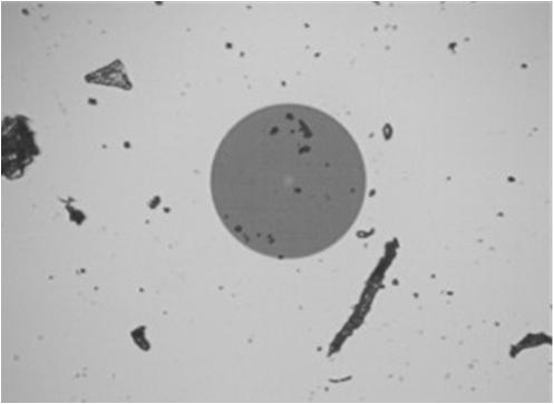
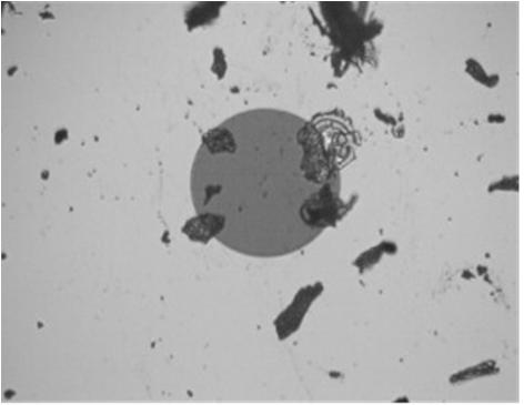
57 MPO-SMF OTDR/Switch Test Case MPO_5_02 MPO_5_09 MPO_5_08 For each fiber having issues, Link view shows which connector(s) will exceed thresholds for insertion loss or reflectance.


")
58 MPO-SMF OTDR/Switch Test Case 8 Fiber 9 MPO(U) Fiber 8 MPO(U) Fiber 8-9 MPO(P) 9 9 8


59 MPO-SMF OTDR/Switch Test Case Fiber 9 MPO(U), after wet /dry 9 8 Fiber 8-9 MPO(P), after wet /dry


60 MMF Live Test Setup HotSpot FiberBox-Demo- SMF/MMF VN C FTB-1v2-iOLM- QUAD SPSB-C-300m SPSB-EF- 34m

61 MMF Test Box
62 Back Up Slides Next 2 slides Unhide if Trouble with Live


63 OTDR Trace- MMF Example Is this accurate? Fault Location? Did these setting produce the cre Was there a Launch / Receive ca
 35m launch cable and standard 302m receive cable")
64 iolm Trace- MMF Example Insert Launch Measurement Encircled Flux (EF) standard compliant (IEC ) 35m launch cable and standard 302m receive cable (OM3).

65 Jamie Humphreys EXFO
66 Multi-Fiber Connectors Inspection and Cleaning Rob Gilberti Sr Product Marketing Manager AFL Test and Inspection Las Vegas, NV September 24, 2017
67 What is so Important about Cleaning and Inspection? Connector contamination and damage is the leading root cause of fiber optic network failures. Lower loss budget requirements make cleaning even more important than before. Inspecting and cleaning before connecting saves troubleshooting costs, downtime and improves performance. Period! Dirt can be transferred from a contaminated connector to a clean connector (i.e. cross-contamination ) All connectors --even brand new jumpers with a factory finish-- should be inspected prior to mating to prevent dirt moving from one connector to another

68 Contaminants and the Connector
69 What Happens to the fiber/connector? Dust and dirt can literally block the light Dirt and oils can cause light to refract and be lost at the connection Particles can prevent proper mating of connectors Dirt can damage connector end face when mating and cause permanent damage cleaning will no longer help

70 Which of these are acceptable Cleaning Methods? Wipe on your sleeve Wipe on your skin Blow on the fiber end Rub with your finger Clean with water Clean with alcohol Clean with tissue/paper towel NONE OF THESE!
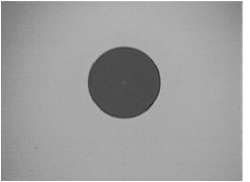
71 What is Clean? Specifies pass/fail requirements for end-face quality before connection Telco Services have widely adopted - Enterprise and data centers have yet to follow Check both sides of the connection Always inspect the fiber first If dirty, clean and inspect again to verify the cleaning was effective Only when both connectors are clean can you proceed with connecting them IEC Standard Definition - IEC :2015


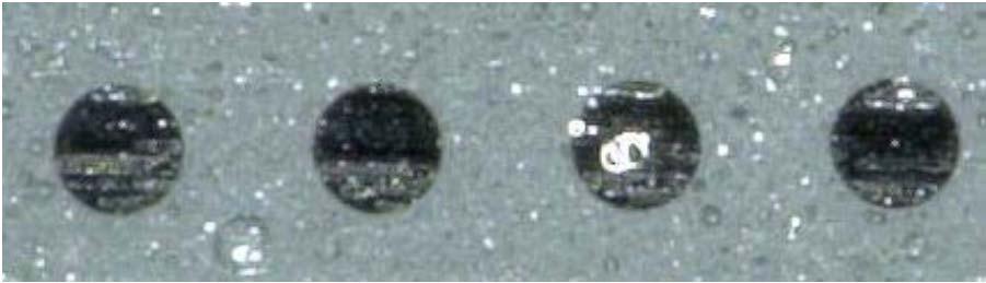
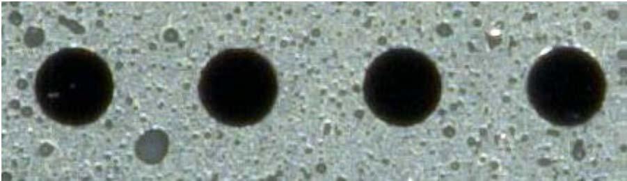
72 Examples Scratched Residue Clean
73 Clean connectors matter!

74 Inspection & cleaning You may have gotten away without it until now MPO/Multi-fiber will force you to rethink your inspection practices 40G/100G will require you to change Example of a dirty MPO end face
75 Multi-Fiber Connectors - More fibers in same space
76 Inspecting Multi-Fiber Connectors For multi-fiber connectors the criteria applies to all fibers in the array It is especially important to clean loose contaminants beyond the contact point Debris can migrate and the close spacing of the fibers increases the chances of contamination causing issues
77 Inspect You need to inspect all end faces in the connector Inspect the entire connector to determine need for cleaning Inspecting first verifies pre-connectorized products have been supplied in good condition Just because a connector comes from the factory with a protective cap does not ensure it is clean
78 Clean You need to be able to clean all end faces quickly and efficiently There are cleaners available today specifically designed for multi-fiber connectors Dry cleaning is quite effective, but is not perfect Use Mech Dry Cleaner for dust Use Wet Clean for Oil/Grease (skin contact) Repeat cleaning process until contamination removed
79 Inspect After cleaning you need to inspect all end faces in the connector again If not clean repeat the process and inspect again Many customers now require proof of inspection to certify installations Saves time and money in the long run

80 What Equipment Do I Need? A quality inspection microscope with appropriate connector tips A scope or adapter specifically designed to inspect multi-fiber connectors. Either pan and scan or wide field of view. Stand-alone or connected to your other test equipment Cleaning supplies Supplies specifically designed for multi-fiber connectors

 Connector Base PC Tip")


81 Single-row MTP/MPO Inspection MPO/MTP Bulkhead MPO/MTP Connector (Ferrule) Single-row (12-pin) Connector Base PC Tip MTP To Probe Position control to view fiber ends within row APC Tip MTPA Base + Tip is required; Base attaches to Probe Connectors are inspected through a bulkhead as shown Adjustment knob scans across row
 Select row Base PC Tip MTP")


82 Multi-row MTP/MPO Inspection MPO/MTP Bulkhead Multi-row MPO/MTP Connector (Ferrule) Select row Base PC Tip MTP 24-fiber, dual-row Connector (2 rows x 12 fibers) To Probe Select fiber within row Connectors are inspected through a bulkhead as shown One adjustment knob scans across row Second adjustment knob selects row (each row contains 12 fibers)

83 Cleaning & Inspection Best Practice START INSPECT ENDFACE ENDFACE CLEAN? PASS PLUG INTO CLEAN MATING CONNECTOR FAIL DRY CLEAN INSPECT ENDFACE Inspect Before You Clean IBYC ENDFACE CLEAN? PASS PLUG INTO CLEAN MATING CONNECTOR WET / DRY CLEAN FAIL FAIL INSPECT ENDFACE ENDFACE CLEAN? PASS PLUG INTO CLEAN MATING CONNECTOR
84 Tools and Methods Available Today 1 Stand-alone Connector Inspection Handheld Probe 4 Inspection reporting using SW Application Creates Inspection reports 2 Equipment-paired connector inspection Bluetooth transfers image & pass/fail results to TEST EQUIPMENT Displays image and pass/fail results on Test Equipment Integrates Inspection results into OTDR & OLTS reports 5 Inspection reporting using Cloud Includes image & pass/fail results 3 Connector inspection using Smart Device Bluetooth transfers image & pass/fail results to Smart Device
85 Lessons learned from the field Contamination is #1 reason for troubleshooting optical networks Inspect through bulkhead, Inspect patchcords if clean don t touch it! Connector dust caps are just that caps with dust in them Contamination has significant Impact on High Data Rates IL/RL Non-IPA solvent for effective, residual free cleaning Alcohol not good enough Optical connector ferrule end-faces tend to become contaminated with skin oils, grease, salt, moisture, fingerprints, dust, lint, grime, flux residue, uncured epoxy
86 Summary/Conclusion Connector contamination and damage is the leading root cause of fiber optic network failures. Due to the number and spacing of fibers in a multi-fiber connector, the problem is multiplied. Proactive inspection and cleaning is not difficult and saves time and money Make Inspection and Cleaning part of your standard practice OPEX is name of game long troubleshooting is deadly
87 Rob Gilberti AFL
88 Using Cloud Based Services to Improve Results and Workflow Management Jim Davis Regional Marketing Engineer Fluke Networks Las Vegas, NV, September 24, 2017
89 Message of presentation, there is a new tool out there, use it
90 Agenda Results management challenges Cloud Based (SaaS) solutions How they work Implementation Connection Options Changing the path of the elephant Adoption Challenges


91 800+ Installers VOCs: Top eight problems (hours wasted) Average amongst all respondents in the previous 30 days
92 Top eight problems: Wrong Configuration (Limit, IDs, Standard,..) Where the SaaS solution can help solve problems
93 Let s look at the process where does it leave us short- and X2 for big projects Tester Configured on-site What are the customer/manufacturer s requirements? How is the tester configured? What Test Limits? What Cable ID s? What Firmware does it have? What is the Calibration date and Period How are test results delivered? When? Today, or in a week (month) when results downloaded ?.pdf format?


94 Cloud Based Service. Minimum Rollout USB Stick in the Cloud Model A Good Start!

95 Getting the results to the cloud is a good start, but there are drawbacks When do they send the data? It is more valuable fresh What if they used the wrong Cable ID still have to go back and edit

96 What if they test to the wrong limit in field The sooner you know, the sooner you can straighten them out Going back to the job site to re-certify can take a lot of time


97 A Better Way, Cloud Based Project Definition Limits, Cable Types, Cable ID are best known by the planner/project-manager With Fiber we don t want TIA or Application limits Custom Limits Which testers are going to do testing Make configurations available to all testers Limits Cables Cable ID
98 Pre-load your Cable IDs into the tester What is the numbering scheme? TIA-606? How do you load the results into your tester? What are the rules for the Excel or CSV file for your tester Know them, use this feature Save time in keying in Cable ID Save time in post processing Select result => Right click => Properties => Edit
99 Project Building Blocks Other Configuration Options Cable Type(s) Test Limit(s) Cable ID Lists(s) Test Regime Copper Fiber BASIC Tier I (LSPM) EXTENDED Tier II (OTDR) End Face Grading 99
100 Application (IEEE) or Cabling Limit? Custom Limit? - Here is a custom Loss Length Limit - And here is an OTDR example - What Reflectance Value will you use?
101 How to Connect a Field Tester to the Cloud Service Wired Connection Bluetooth/Wifi to Cell Phone Wifi to Cloud

102 Cloud Based Management. Standard Rollout PM defines entire Project in a SAAS
103 Visibility for ACE s & Manufacturers Opportunities: Are correct limits are used? Is there a failing test result/otdr trace? Is the reference set correctly? Is the value good? Does the TRC Check show good cords? Are the performance margin as expected? What is the progress, how many tests were run?


104 Added bonus of Cloud service Asset Management View of all testers Firmware Cal date Location when last updated?
105 Cloud Based Solutions Challenges Projects are realized in Phases Projects are realized by multiple Teams Projects are realized by multiple companies (organizations) Subcontractors All Participants will need access to Cloud Based Account Permission Levels must be considered LWL 3.0 f. Manuf. & Consultants V1.0 (C) FlukeNetworks


106 Cloud Based Results Management Solutions offer efficiencies, but they have to be used Simple implementation share results to all interested parties faster Better implementation Send configurations to one or more testers Especially for custom fiber limits Sending Cable ID s is a great time saver Best Implementation get teams to use system Future benefits will be developed for data that is available
107 In Conclusion The solutions have to be used Use model can be simple Thumb Drive in the Cloud Or more complex Pre-load Cable ID s and Test Configurations Upload results frequently Keep your tester in the field Avoid Common problems Get paid faster Send results today
108 , Gracias, Obrigado Jim Davis Fluke Networks 6920 Seaway Blvd Everett, WA 98271
Fibre (TIA) Field Test Specification
 Field Test Specification") This document has been prepared to aid consultants or engineers in developing contractual specifications covering the testing of duplex fibre optic cabling installations. It is offered as a general guide.
This document has been prepared to aid consultants or engineers in developing contractual specifications covering the testing of duplex fibre optic cabling installations. It is offered as a general guide.
Reflectance, The Hidden Danger That Increases Bit Error Rates in Your Fiber Networks Denver, May 22nd, 2010
 Reflectance, The Hidden Danger That Increases Bit Error Rates in Your Fiber Networks Denver, May 22nd, 2010 Adrian Young Sr. Customer Support Engineer Foreword Reflectance is measured using an Optical
OLTS vs OTDR Tier-2 Expert; How far from Tier-1?
 OLTS vs OTDR Tier-2 Expert; How far from Tier-1? Christian Till, Application Engineer 2016/12/09 1 Why this industry is exciting! Bandwidth grows like crazy Global DC traffic 5ZB now, 10.4ZB 2019 Hyperscale
Field Testing and Troubleshooting of PON LAN Networks per IEC Jim Davis Regional Marketing Engineer Fluke Networks
 Field Testing and Troubleshooting of PON LAN Networks per IEC 61280-4 Jim Davis Regional Marketing Engineer Fluke Networks Agenda Inspection and Cleaning APC vs UPC PON basics Wavelengths Architecture
Ensuring Cabling Performance in the Customer-Owned Outside Plant
 Ensuring Cabling Performance in the Customer-Owned Outside Plant Needs to be able to qualify the installation to validate bandwidth requirements are met Future high bandwidth applications Future Proof
Ensuring Cabling Performance in the Customer-Owned Outside Plant. Keith Foord Product Manager Greenlee Communications
 Ensuring Cabling Performance in the Customer-Owned Outside Plant Keith Foord Product Manager Greenlee Communications Introduction: Outside plant fiber networks require low reflectance terminations for
The Rise of Tier 2 Testing
 The Rise of Tier 2 Testing Why enterprises today demand better visibility into their fiber infrastructure Unprecedented demand for more bandwidth, faster network speeds, lower latency, and improved data
VTI Services Technical Bulletin (TB) OTDR Measurement of Installed Optical Fibre Cabling Permanent Links and Links
 OTDR Measurement of Installed Optical Fibre Cabling Permanent Links and Links") VTI Services Technical Bulletin (TB) OTDR Measurement of Installed Optical Fibre Cabling Permanent Links and Links TB Number 004 This bulletin is supplied for information only and is intended to provide
VTI Services Technical Bulletin (TB) OTDR Measurement of Installed Optical Fibre Cabling Permanent Links and Links TB Number 004 This bulletin is supplied for information only and is intended to provide
AS/NZS ISO/IEC :2012
 AS/NZS ISO/IEC 14763.3:2012 (ISO/IEC 14763-3:2011, MOD) Australian/New Zealand Standard Telecommunications installations Implementation and operation of customer premises cabling Part 3: Testing of optical
This is a preview - click here to buy the full publication
 ISO/IEC 14763-3 CONSOLIDATED VERSION Edition 2.1 2018-08 colour inside Information technology Implementation and operation of customer premises cabling Part 3: Testing of optical fibre cabling INTERNATIONAL
Link loss measurement uncertainties: OTDR vs. light source power meter By EXFO s Systems Engineering and Research Team
 Link loss measurement uncertainties: OTDR vs. light source power meter By EXFO s Systems Engineering and Research Team INTRODUCTION The OTDR is a very efficient tool for characterizing the elements on
INTERNATIONAL STANDARD
 INTERNATIONAL STANDARD ISO/IEC 14763-3 First edition 2006-06 Information technology Implementation and operation of customer premises cabling Part 3: Testing of optical fibre cabling Reference number ISO/IEC
RLH Industries, Inc. Cleaning and Testing Fiber Optic Cable. Reference Guide MD A 0507
 RLH Industries, Inc. Cleaning and Testing Fiber Optic Cable Reference Guide MD-019 2014A 0507 RLH Industries, Inc. Copyright 2013 RLH Industries, Inc. All rights reserved. No part of this document may
MT-RJ Optical Fiber System Field Testing
 MT-RJ Optical Fiber System Field Testing Table of Contents INTRODUCTION... 3 TEST JUMPERS... 4 LAUNCH CONDITIONS... 4 MT-RJ TEST KITS... 5 MT-RJ SYSTEM TESTING: Fixed transmit and receive (SC or ST-style)
infrastructure for 10, 40 and 100Gbits/s readiness
 Field Testing of fiber optic infrastructure for 10, 40 and 100Gbits/s readiness Christian Schillab Product Manager Media Test Fluke Networks Europe Member BritishStandards Institute Working Group TCT 7/
EXECUTING HIGHLY ACCURATE FIBER MEASUREMENTS IN A FRACTION OF THE TIME
 10 /0 /100Gb/s transmission links are typically shared by a vast number of application and users. EXECUTING HIGHLY ACCURATE FIBER MEASUREMENTS IN A FRACTION OF THE TIME Claiming that they are most of the
M310 Data Center OTDR
 Designed for Data Center Testing, Troubleshooting and Documentation Features Event Dead Zone 0.8 m Attenuation Dead Zone
The True Value of Connector Inspection: New Challenges and Best Practices
 The True Value of Connector Inspection: New Challenges and Best Practices Vincent Racine Product Line Manager August 2011 1 Table of contents 1 Best Practices 2 Connector Inspection Tools 3 Connector Inspection
Fibre Specification Standards
 Fibre Specification Standards User Manual The most important thing we build is trust Cobham Wireless - Coverage Table of Contents 1. Single-mode Fibre to ITU-T Recommendation G.652 3 2. SC/APC Mated Pair
White Paper: Fiber Contamination, Cleaning and Inspection. Introduction.
 White Paper: Fiber Contamination, Cleaning and Inspection. Introduction. Despite industry best practice of inspecting and cleaning fiber optic endfaces, contaminated connections remain the number one cause
M210 Multifunction Micro OTDR
 Test, Troubleshoot and Document Single-mode and Multimode Fiber Networks Features 30 db dynamic range single-mode 16-hour battery life Remote display capable Touch and Test intuitive user interface New
Fiber Tes)ng 101 Essen)als Every Network Analyst Needs to Know. David S(llwell BCNET Oscar Rondon BCNET Gwenn Amice - EXFO
ng 101 Essen)als Every Network Analyst Needs to Know. David S(llwell BCNET Oscar Rondon BCNET Gwenn Amice - EXFO") Fiber Tes)ng 101 Essen)als Every Network Analyst Needs to Know David S(llwell BCNET Oscar Rondon BCNET Gwenn Amice - EXFO Workshop format The Workshop is going to start with three short lecture style power
Fiber Tes)ng 101 Essen)als Every Network Analyst Needs to Know David S(llwell BCNET Oscar Rondon BCNET Gwenn Amice - EXFO Workshop format The Workshop is going to start with three short lecture style power
CHALLENGE OF THE NEW OPTICAL FIBRE TECHNOLOGIES
 THE CHALLENGE OF THE NEW OPTICAL FIBRE TECHNOLOGIES 17th September 2002 Botanical Gardens Birmingham The Way We Were 1GbE and 10GbE OF Categories Channel Design Cleaning SFF Connecting Hardware Testing
M310 Enterprise OTDR. Designed for Enterprise Network Testing, Troubleshooting and Documentation. or (800) , (603)
 , (603)") Designed for Enterprise Network Testing, Troubleshooting and Documentation Features Industry leading TruEvent analysis Short dead zones provide precise testing of closely spaced events Front Panel and
Designed for Enterprise Network Testing, Troubleshooting and Documentation Features Industry leading TruEvent analysis Short dead zones provide precise testing of closely spaced events Front Panel and
M310 Enterprise OTDR. Designed for Enterprise Network Testing, Troubleshooting and Documentation. or (800) , (603)
 , (603)") Designed for Enterprise Network Testing, Troubleshooting and Documentation Features Integrated Optical Power Meter and Visual Fault Locator Short dead zones provide testing of closely spaced events Industry
Designed for Enterprise Network Testing, Troubleshooting and Documentation Features Integrated Optical Power Meter and Visual Fault Locator Short dead zones provide testing of closely spaced events Industry
M700-Series Multifunction OTDR
 M700-Series Multifunction OTDR Test, Troubleshoot and Document Single-mode and Multimode Fiber Networks Test Modes Full Auto OTDR Normal (point-to-point) fiber cable construction testing and fault location
FTTH NETWORK TESTING: REAL APPLICATIONS USING THE OLTS METHOD
 FTTH NETWORK TESTING: REAL APPLICATIONS USING THE OLTS METHOD 157 APPLICATION NOTE Mario Simard, Product Manager, Optical Business Unit The purpose of any fiber-optic network is to perform high-speed,
M210 Multifunction Micro OTDR
 Test, Troubleshoot and Document Single-mode and Multimode Fiber Networks Features 30 db dynamic range single-mode 16-hour battery life Remote display capable Touch and Test intuitive user interface New
Accelerating NBN fiber testing. Tom Ronan Marketing Lead Fiber Optics Melbourne
 Accelerating NBN fiber testing and workforce Performance. Tom Ronan Marketing Lead Fiber Optics Melbourne Agenda Network Elements and Parameters Distributed Fiber Network (DFN) Construction Network Activation
A Quick Start Guide to Fiber-to-theAntenna (FTTA) Installation and Maintenance Testing. Vol. 2 Tier 2 Certification
 Installation and Maintenance Testing. Vol. 2 Tier 2 Certification") A Quick Start Guide to Fiber-to-theAntenna (FTTA) Installation and Maintenance Testing Vol. 2 Tier 2 Certification A Quick Start Guide to Fiber-to-the-Antenna enna (FTTA) Installation and Maintenance Testing
A Quick Start Guide to Fiber-to-theAntenna (FTTA) Installation and Maintenance Testing Vol. 2 Tier 2 Certification A Quick Start Guide to Fiber-to-the-Antenna enna (FTTA) Installation and Maintenance Testing
OPX-BOX. Platform Highlights. Software Support. Key Features
 Ultra Compact, Highly Versatile OTDR with Bluetooth Wireless and USB Control The VeEX is an ultra-compact, OTDR designed to operate remotely using Fiberizer software. The unit can be controlled via USB
MTTplus Modular Test Platform
 MTTplus-410 Fiber Optics Test Module 2017 MTTplus Modular Test Platform The Fiber Optics module for the VeEX MTTplus supports a full range of test functions including OTDR, OPM, Light Source and VFL. Geo
Ensuring the Health of Tomorrow s Fiber LANs Part II OTDR Trace Analysis Become an Expert Troubleshooter with Advanced OTDR Trace Analysis
 Ensuring the Health of Tomorrow s Fiber LANs Part II OTDR Trace Analysis Become an Expert Troubleshooter with Advanced OTDR Trace Analysis Experience designing cable and network testers has enabled a breakthrough
A Quick Start Guide to Fiber-to-the-Antenna (FTTA) Installation and Maintenance Testing. Vol. 2 Tier 2 Certification
 Installation and Maintenance Testing. Vol. 2 Tier 2 Certification") A Quick Start Guide to Fiber-to-the-Antenna (FTTA) Installation and Maintenance Testing Vol. 2 Tier 2 Certification Notice Copyright Every effort was made to ensure that the information in this document
A Quick Start Guide to Fiber-to-the-Antenna (FTTA) Installation and Maintenance Testing Vol. 2 Tier 2 Certification Notice Copyright Every effort was made to ensure that the information in this document
OTDR II. Tier-2 Optical Time Domain Reflectometer for Multimode and Single-mode Fiber Cabling
 Tier-2 Optical Time Domain Reflectometer for Multimode and Single-mode Fiber Cabling Tier-2 Optical Time Domain Reflectometer for Multimode and Single-mode Fiber Cabling The OTDR II is the first tablet
White Paper: Standard-Compliant Certification & Best Practices Ensure Fiber End-face Cleanliness to Eliminate the #1 Cause of Fiber Failure
 White Paper: Standard-Compliant Certification & Best Practices Ensure Fiber End-face Cleanliness to Eliminate the #1 Cause of Fiber Failure White Paper: Standard-Compliant Certification & Best Practices
FTB-7400E Metro/CWDM OTDR METRO/CORE AND CWDM NETWORK FIBER CHARACTERIZATION
 METRO/CORE AND CWDM NETWORK FIBER CHARACTERIZATION i OLM R E A D Y GLOBAL PORTABLE FIBER OPTIC TEST EQUIPMENT MARKET LEADERSHIP AWARD High-resolution OTDR covering longer metro distances and ITU-based
A. General: Horizontal and backbone cabling shall be verified in accordance with ANSI/TIA/EIA-568-C and the addendum for fiber optic testing.
 3.4 TESTING OF FIBER OPTICS CABLING A. General: Horizontal and backbone cabling shall be verified in accordance with ANSI/TIA/EIA-568-C and the addendum for fiber optic testing. B. General: In the event
White Paper Fiber optic connections: check and clean first, then connect!
 White Paper Fiber optic connections: check and clean first, then connect! How installers ensure the quality of their work Fiber optic connections: check and clean first, then connect! How installers ensure
M700-Series OTDRs. or (800) , (603)
 , (603)") Features M700 Compact QUAD OTDR M700 OTDR with DFS1 Digital FiberScope Integrated OPM and VFL (650 nm) Inspection capable with the DFS1 FiberScope Full Auto, Expert, and Real-Time OTDR test modes Automatic
Features M700 Compact QUAD OTDR M700 OTDR with DFS1 Digital FiberScope Integrated OPM and VFL (650 nm) Inspection capable with the DFS1 FiberScope Full Auto, Expert, and Real-Time OTDR test modes Automatic
FLX380-30x FlexTester OTDR
 Features 3rd generation hand-held, all-in-one OTDR, Source, Power Meter, VFL Icon-based LinkMap display with pass/fail for easy network analysis Patented in- or out-of-service testing from a single port
Acceptance Requirements. Fibre Optic Systems. Revised 12/2017. December 5th, Alexander Kölbel
 December 5th, 2017 Acceptance Requirements Fibre Optic Systems Revised 12/2017 Alexander Kölbel +49 6190 8880-40 alexander.koelbel@datwyler.com Dätwyler Cables GmbH, Auf der Roos 4-12, 65795 Hattersheim,
Fibre Characterisation and FTTx New challenges
 Fibre Characterisation and FTTx New challenges Broadband Technology Event Rotterdam, November 10th, 2009 Nicolas CARLIER France & Benelux RSM nicolas.carlier@exfo.com What is Fiber Characterisation when
Kingfisher KI-3800 Light Source. Inexpensive handheld source for testing and commissioning optical fibre networks. Compact and rugged,
 TEST EQUIPMENT POWER METERS, LIGHT SOURCES Kingfisher KI-9800 Light Source Kingfisher KI-3800 Light Source Inexpensive handheld source for testing and commissioning optical fibre networks. Compact and
Basic Professional Fiber Optic Installation
 Basic Professional Fiber Optic Installation QUICK SUMMARY Length: 32 hours; or 40 hours with Fiber Optic Association CFOT certification Hands-on Activities: 40 activities, 70-75 % Text/Field Reference:
Fiber Optic Connector Cleaning and Inspection Kit Instructions
 Instruction Sheet 860376037 Rev E, March 2018 Fiber Optic Connector Cleaning and Inspection Kit Instructions General This instruction sheet describes the use of the CommScope Fiber Optic Connector Cleaning
FTB-720 LAN/WAN Access OTDR OPTIMIZED FOR MULTIMODE AND SINGLEMODE ACCESS NETWORK TESTING
 Provided by www.aaatesters.com FTB-720 LAN/WAN Access OTDR OPTIMIZED FOR MULTIMODE AND SINGLEMODE ACCESS NETWORK TESTING i OLM R E A D Y 2014 GLOBAL PORTABLE FIBER OPTIC TEST EQUIPMENT MARKET LEADERSHIP
Noyes OFL 250B Specs Provided by
 Noyes OFL 250B Specs Provided by www.aaatesters.com OFL 250 Handheld OTDR The Noyes OFL 250 from AFL Telecommunications is a single-mode OTDR with an integrated Optical Power Meter (OPM), Source (OLS),
TRM 2.0 Test Results Manager All-In-One Comprehensive Analysis and Reporting Software
 TRM 2.0 asic Software Features Generate professional acceptance reports including: OTDR traces Certification loss results/opm loss results Connector Inspection Results Create certification results and
Connections You Can Count On.
 Connections You Can Count On. XPRESS ULTRA FIBER CONNECTOR PRODUCT GUIDE - CLEANING & INSPECTION - TESTING AND TROUBLE SHOOTING - XPRESS ULTRA FIBER CONNECTORS - INSTALLATION KITS Connections You Can Count
ACCESS Master MT9085 Series. Product Introduction
 ACCESS Master MT9085 Series Product Introduction Strengthen of MT9085 Series: 1/5 All Optical Fiber Evaluation Functions in One Tester The ACCESS Master MT9085 series is an all-inone tester with OTDR,
OPX-BOXe Rugged, Pocket-sized Mini OTDR
 OPX-BOXe Rugged, Pocket-sized Mini OTDR Highly Versatile OTDR with Wireless and USB Control The VeEX OPX-BOXe is an ultra-compact, OTDR designed to operate remotely using Fiberizer software. The unit can
INTERNATIONAL STANDARD
 INTERNATIONAL STANDARD IEC 61280-4-1 Edition 2.0 2009-06 Fibre-optic communication subsystem test procedures Part 4-1: Installed cable plant Multimode attenuation measurement IEC 61280-4-1:2009(E) THIS
Fiber Optics for Todays Industry Applications
 Hands-On Fiber Optics for Todays Industry Applications (A Non-Telephone Company Course) Course Description This Hands-On course is designed to provide technicians with a practical understanding and Hands-On
FTBx-740C-DWC TUNABLE OTDR C-BAND DWDM METRO ETHERNET LINK CHARACTERIZATION
 C-BAND DWDM METRO ETHERNET LINK CHARACTERIZATION GLOBAL PORTABLE FIBER OPTIC TEST EQUIPMENT MARKET LEADERSHIP AWARD NEW OTDR GENERATION Tunable DWDM OTDR for testing through MUX/DEMUX channels to provide
ENCIRCLED FLUX (EF) TEST SOLUTIONS
 TEST SOLUTIONS") ENCIRCLED FLUX (EF) TEST SOLUTIONS Tier-1/2 solutions with controlled source launch conditions for maximum accuracy and repeatability designed to remove uncertainty from multimode fiber testing. KEY FEATURES
ENCIRCLED FLUX (EF) TEST SOLUTIONS Tier-1/2 solutions with controlled source launch conditions for maximum accuracy and repeatability designed to remove uncertainty from multimode fiber testing. KEY FEATURES
FLX380 and OFL280 FlexTester Series
 FLX380 and OFL280 FlexTester Series User Guide www.aflglobal.com or +1 (800) 321-5298, +1 (603) 528-7780 Contents Safety Information... 4 General Information... 5 Contacting Customer Service...5 Recommended
OptiFiber Pro OTDR Built for the enterprise
 OptiFiber Pro OTDR Built for the enterprise As enterprise networks and datacenter architectures evolve, IT infrastructure administrators demand better OTDR technology to maintain fiber network performance.
FLX380-30x FlexTester3 OTDR
 Features 3rd generation hand-held, all-in-one OTDR, OLS, OPM, VFL Patented in- or out-of-service testing from a single port 42/42 db dynamic range @ 1310/1550 nm; test up to 1x128 PON Industry-leading
Designed for Enterprise Fiber
 Datasheet: OptiFiber Pro OTDR - The OptiFiber Pro OTDR is the Tier 2 (extended) fiber certification solution and part of the Versiv Cabling Certification product family. The Versiv line also includes copper
ASSMANN ELECTRONIC GmbH ASSMANN SYSTEM GUARANTEE. DIGITUS Professional Fiber Optic Cabling System. Appendix B - Provisions for acceptance
 ASSMANN ELECTRONIC GmbH ASSMANN SYSTEM GUARANTEE DIGITUS Professional Fiber Optic Cabling System Appendix B - Provisions for acceptance Page 1 Table of contents 1. Acceptance test of the installation link
ENCIRCLED FLUX (EF) TEST SOLUTIONS SPSB-EF LAUNCH MODE CONDITIONER AND FLS-600-NS1548 LIGHT SOURCE DESIGNED FOR CONTROLLED MULTIMODE LOSS TESTING
 TEST SOLUTIONS SPSB-EF LAUNCH MODE CONDITIONER AND FLS-600-NS1548 LIGHT SOURCE DESIGNED FOR CONTROLLED MULTIMODE LOSS TESTING") ENCIRCLED FLUX (EF) TEST SOLUTIONS SPSB-EF LAUNCH MODE CONDITIONER AND FLS-600-NS1548 LIGHT SOURCE DESIGNED FOR CONTROLLED MULTIMODE LOSS TESTING Tier-1/2 solutions with controlled source launch conditions
ENCIRCLED FLUX (EF) TEST SOLUTIONS SPSB-EF LAUNCH MODE CONDITIONER AND FLS-600-NS1548 LIGHT SOURCE DESIGNED FOR CONTROLLED MULTIMODE LOSS TESTING Tier-1/2 solutions with controlled source launch conditions
OWL. Laser OWL Series. Operations Guide. Singlemode Light Sources. Optical Wavelength Laboratories. Date: October 1, 2015
 Laser OWL Series Operations Guide Singlemode Light Sources OWL Optical Wavelength Laboratories Operations Guide Laser OWL and Laser OWL HP Singlemode Light Sources Date: October 1, 015 Version.5 Optical
M210 Multifunction Micro OTDR
 Test, Troubleshoot and Document Single-mode and Multimode Fiber Networks Features 30 db dynamic range single-mode 16-hour battery life Remote display capable Touch and Test intuitive user interface New
Field Test Procedure for Optical Fibre Link Measurements
 Application Notes Field Test Procedure for Optical Fibre Link Measurements Issued April 2014 Abstract After fiber optic cables are installed, spliced and terminated, they must be tested. For every fiber
Hands-On Fiber Optic ISP / OSP Combo-Tech Splicing, Termination & Testing
 Hands-On Splicing, Termination & Testing BICSI CECs This course has been approved for CEC credits by BICSI. Please read below for a breakdown of the credits that we offer for this course. For more information
4120 Fire Alarm Network Reference
 4120 Fire Alarm Network Reference Features Autocall 4120 Fire Alarm Network communications are available for wired or fiber optic connections Wired communications are available on Network Interface Cards
Qualification Test Report LightCrimp* Plus Singlemode and Multimode LC Connector (Field Installable)
") Qualification Test Report LightCrimp* Plus Singlemode and Multimode LC Connector (Field Installable) 501-586 26Feb09 Rev F 1. INTRODUCTION 1.1. Purpose Testing was performed on Tyco Electronics LightCrimp*
Qualification Test Report LightCrimp* Plus Singlemode and Multimode LC Connector (Field Installable) 501-586 26Feb09 Rev F 1. INTRODUCTION 1.1. Purpose Testing was performed on Tyco Electronics LightCrimp*
Hands-On Fiber Optics ISP/OSP - Advanced Combo- Tech
 Hands-On Fiber Optics ISP/OSP - Advanced Combo- Tech Course Description This Hands-On 3-day course has been customized to provide technicians with a practical understanding of fiber optic theory and fiber
Hands-On CAT 5/6 & Fiber Optic Installer
 Hands-On BICSI CECs This course has been approved for CEC credits by BICSI. Please read below for a breakdown of the credits that we offer for this course. For more information regarding BICSI please visit
M-Series Compact OTDRs User s Guide
 M-Series Compact OTDRs User s Guide Limited Warranty One Year Limited Warranty All Noyes products are warranted against defective material and workmanship for a period of one year from the date of shipment
OptiFiber Pro OTDR Built for the enterprise
 OptiFiber Pro OTDR Built for the enterprise As enterprise networks and datacenter architectures evolve, IT infrastructure administrators demand better OTDR technology to maintain fiber network performance.
Datasheet: OptiFiber Pro OTDR
 Datasheet: OptiFiber Pro OTDR The OptiFiber Pro OTDR is the Tier 2 (extended) fiber certification solution and part of the Versiv Cabling Certification product family. The Versiv line also includes copper
Certified Fibre Optic Specialist - Testing
 Certified Fibre Optic Specialist - Testing COURSE DESCRIPTION: This training program is designed to introduce the student to the process of fibre optic network testing. It is intended for those looking
Advancing Fiber Optic Connectivity
 Advancing Fiber Optic Connectivity Fusion Spice-On Connectors by Brad Everette, America Ilsintech, Dallas, TX and Seung-Min Lee, Ilsintech, Daejeon, South Korea Presentation Overview Advancements in Fiber
palmotdr Series Handheld OTDR
 palmotdr Series Handheld OTDR Most Compact High-Performance OTDR Comprehensive fiber applications, ideal for LAN/WAN/FTTx certification & trouble-shooting: SM: 1310/1490/1550, 1625/1650nm (with filter),
Best Practice Briefing
 Best Practice Briefing Fiber Optic Connector Handling, Inspection, andcleaning microwave photonic systems Expand Your RF Horizons Briefing Overview Personnel Safety & Best Practices Insertion Loss (IL)
Flexibility, scalability andsecurity
 THE OF INFORMATION TECHNOLOGY SYSTEMS An Official Publication of BICSI January/February 2014 l Volume 35, Number 1 data center Flexibility, scalability andsecurity plus + The Next Five Years in AV + Measuring
Fiber Optic and CAT 5, 6, 7 and 8 Installer Premise Cabling
 Hands-On Fiber Optic and CAT 5, 6, 7 and 8 Installer Premise Cabling Certification Course Description This Hands-On course is customized to give Technicians the confidence and skills to maintain Fiber
OTDR. Optical Time Domain Reflectometer. User Guide
 OTDR Optical Time Domain Reflectometer User Guide Copyright 2013 2015 EXFO Inc. All rights reserved. No part of this publication may be reproduced, stored in a retrieval system or transmitted in any form,
Datasheet: OptiFiber Pro OTDR
 Datasheet: OptiFiber Pro OTDR Accelerates enterprise fiber troubleshooting and certification. The OptiFiber Pro OTDR is the Tier 2 (extended) fiber certification solution and part of the Versiv Cabling
FX150 OTDR. Platform Highlights. Key Features
 Mini OTDR for FTTx and Metro fiber networks FX150 mini OTDR is designed for the installation, maintenance and troubleshooting of FTTx, Mobile FrontHaul/BackHaul and Metro fiber networks. The compact, lightweight
ENGINEERING COMMITTEE Interface Practices Subcommittee AMERICAN NATIONAL STANDARD ANSI/SCTE
 ENGINEERING MITTEE Interface Practices Subcommittee AMERICAN NATIONAL STANDARD ANSI/SCTE 240 2017 SCTE Test Procedures for Testing CWDM Systems in Cable Telecommunications Access Networks NOTICE The Society
Datasheet: OptiFiber Pro OTDR
 Datasheet: OptiFiber Pro OTDR Accelerates enterprise fiber troubleshooting and certification. The OptiFiber Pro OTDR is the Tier 2 (extended) fiber certification solution and part of the Versiv Cabling
Applications Engineering Notes
 Applications Engineering Notes Document Title Document Number Revision Number Product Specification and Qualification Test Report: IBC Brand Fiber Optic Connector Cleaner MT38 II AEN-1146 Issue Effective
Optical Return Loss Measurement by Gregory Lietaert, Product Manager
 White Paper Optical Return Loss Measurement by Gregory Lietaert, Product Manager Introduction With the increasing frequency of high-speed transmission systems and DWDM deployment, optical return loss (ORL)
SECTION TESTING OF FIBER OPTIC CABLES
 SECTION 27 08 23 TESTING OF FIBER OPTIC CABLES PART 1 GENERAL 1.01 DESCRIPTION A. The work covered by this section of the Specifications includes all labor necessary to perform and complete such construction,
TRM 2.0 Test Results Manager All-In-One Comprehensive Analysis and Reporting Software
 TRM 2.0 Basic Software Features Generate professional acceptance reports including: OTDR traces Certification loss results/opm loss results Connector end-face images from FOCIS and DFS1 Create certification
FlexScan OTDR With SmartAuto and LinkMap
 FlexScan OTDR With SmartAuto and LinkMap Quick Reference Guide Test & Inspection Controls, Display, Interfaces 1 2 4 8 1. Power button 2. Power jack (5 VDC) 3. Charge/AC indicator 4. USB ports 5. OTDR/source
FTB-730 PON FTTx/MDU OTDR OPTIMIZED FOR ACCESS FIBER DEPLOYMENTS AND TROUBLESHOOTING
 OPTIMIZED FOR ACCESS FIBER DEPLOYMENTS AND TROUBLESHOOTING i OLM R E A D Y 2014 GLOBAL PORTABLE FIBER OPTIC TEST EQUIPMENT MARKET LEADERSHIP AWARD The perfect tool for field technicians who need to seamlessly
FTB/FTBx-740C-CWDM Tunable OTDR 18-WAVELENGTH CWDM OTDR FOR METRO ETHERNET AND C-RAN LINK CHARACTERIZATION
 18-WAVELENGTH CWDM OTDR FOR METRO ETHERNET AND C-RAN LINK CHARACTERIZATION NEW OTDR GENERATION A single and compact OTDR unit that covers all 18 CWDM ITU channels for testing through MUX/DEMUX channels,
GAMMA OTDR application consists of main window and menu. Using menu user can operate in different modes of application.
 GAMMA OTDR Introduction...1 Using GAMMA OTDR...1 Application main window...1 Menu description...2 file...2 instrument...2 mode...5 events...9 view...11 Introduction GAMMA OTDR is the first Android application
Intelligent Optical Link Mapper (iolm)
") Intelligent Optical Link Mapper (iolm) AUTOMATED, EXPERT-LEVEL SINGLEMODE FIBER TESTING Available on: FTB-700 OTDR Series FTB-7000 OTDR Series Powered by T E C H N O L O G Y Patent protection applies to
Intelligent Optical Link Mapper (iolm) AUTOMATED, EXPERT-LEVEL SINGLEMODE FIBER TESTING Available on: FTB-700 OTDR Series FTB-7000 OTDR Series Powered by T E C H N O L O G Y Patent protection applies to
palmotdr Series Handheld OTDR
 palmotdr Series Handheld OTDR Most Compact High-Performance OTDR Comprehensive fiber applications, ideal for LAN/WAN/FTTx certification & trouble-shooting: SM: 1310/1490/1550, 1625/1650nm (with filter),
Benefits of Enhanced Event Analysis in. Mark Miller
 Benefits of Enhanced Event Analysis in Data Center OTDR Testing Mark Miller Dr. Fang Xu AFL/Noyes Test & Inspection Overview Challenges Topics Techniques and Improvements Benefits of enhanced event analysis
IDEAL INDUSTRIES, INC. USER MANUAL IDEAL OTDR
 IDEAL INDUSTRIES, INC. USER MANUAL IDEAL OTDR Revision: March 31, 2016 Copyright 2013 2016 EXFO Inc. All rights reserved. No part of this publication may be reproduced, stored in a retrieval system or
FastReporter 2 DATA POST-PROCESSING SOFTWARE
 DATA POST-PROCESSING SOFTWARE Consolidated data management and post-processing tool designed to increase the reporting productivity for connector endface inspection and all types of optical-layer testing:
LAB REPORT SUBMISSION COVER PAGE ETN4106 OPTOELECTRONICS AND OPTICAL COMMUNICATIONS
 1/10 FACULTY OF ENGINEERING LAB REPORT SUBMISSION COVER PAGE ETN4106 OPTOELECTRONICS AND OPTICAL COMMUNICATIONS TRIMESTER 3, SESSION 2016/2017 Student Name: Student ID: Degree Major (please circle): EE
VePAL FX300 Portable OTDR, Optical Power Meter, Visual Fault Locator, and Laser Source Test Set
 VePAL Portable OTDR, Optical Power Meter, Visual Fault Locator, and Laser Source Test Set Multi-Functional Test Platform for Optical Fiber Networks VeEX VePAL is a full featured Optical test solution for
DWDM OTDR with Tunable Laser MTP-200-D100. Hand-held High Performance OTDR. Series
 MTP-200-D100 Hand-held High Performance OTDR DWDM OTDR with Tunable Laser Series Multi-Function and High Performance OTDR Testing 96 C-band wavelengths Dynamic range up to 38dB Short zone: EDZ 1m, ADZ