Circuits, Diagrams & Power. Rodger Schmidt ASSA ABLOY EMSO Group HES/Folger Adams/Securitron/Adams Rite/Alarm Controls
|
|
|
- Elisabeth Anthony
- 6 years ago
- Views:
Transcription

1 Circuits, Diagrams & Power Rodger Schmidt ASSA ABLOY EMSO Group HES/Folger Adams/Securitron/Adams Rite/Alarm Controls

2 2
3 Class Agenda Access Control the Basics Laying out the circuit & diagram Wiring circuit, lets make it work! What is the heart of the EAC system? Power Supplies, Boards and the Circuit Exiting, Switches, Existing Locksets Team System Project Open Discussion and Questions 3
4 Access Control Basics Basic Reader All inputs and outputs necessary to control door hardware are located in the control panel (above door or centrally located) Access requests sent to host PC via control panel Power Supply Power Supply
5 Traditional Electronic Access Control Wiegand Data Strike DPS REX 12 / 24 VDC 12 / 24 VDC Access Controller Multiple Readers Power Supply 120VAC Traditional solution Electromechanical hardware requiring hard wiring for power and communication Typically nonproprietary product solutions for access control locking, signaling, and monitoring Ideal for high security or complex electrified openings Usually requires access control panels and interface devices in a secure closet not above ceiling NEC Code Applies 5
6 Typical Online Access Control Ethernet (IEEE* 802.3af) Wiegand Data 12 / 24 VDC 12 / 24 VDC Strike DPS REX 3 rd Party Reader Interface 3 rd Party Access Controller Power Supply 120 VAC Power Supply 120 VAC OEM Access Control System 6 6
 12 / 24 VDC 12 / 24 VDC 3 rd Party Reader Interface 3 rd Party Access Controller ELock Power Wiegand Data REX DPS")
7 Integrated Wiegand Access Control: Harmony Access 600 Symphony SE LP10 Ethernet (IEEE* 802.3af) 12 / 24 VDC 12 / 24 VDC 3 rd Party Reader Interface 3 rd Party Access Controller ELock Power Wiegand Data REX DPS (mortise only) OEM Access Control System 7 7
 WAP Add Joe and Mary access M F 6AM6PM Remove Stuart Jane lost her card.")

8 Ethernet (IEEE* 802.3af) WiFi Access Control: v.s2 P2 Access 800 WI1 Access 800 PWI1 IN GHz ( b/g/n) WAP Add Joe and Mary access M F 6AM6PM Remove Stuart Jane lost her card. Don t grant access for her old card. Suzie used her card on 07:47:12 Door opened on 5:44:23 My battery voltage is VDC 2,400 Users 10,000 Events OEM Access Control System 8 8

9 Our focus today! Key Components Brick and Mortar


10 Where to start? Relationships, Drawings, Codes AIA Docs Divisions / CSI Change Div 1: General Div 08: Doors and WindowsHardware Div 13: Special Construction: Old Version Div 26: Electrical Div 27: Communications Div 28: Electronic Safety & Security RELATIONSHIPS
11 Occupancy IBC 2015 Chapter 3 How it is used Groupings A Assembly A1, A2, A3, A4, A5 B Business E Educational Factory & Industrial F1, F2 High Hazard H1, H2, H3, H4, H5 Institutional I1, I2, I3, I4 Mercantile Residential R1, R2, R3, R4 Storage S1, S2 Utility & Miscellaneous 1 Movie theaters, 2 Food & Drink 3 Comm Halls, 4 Arenas, 5 Stadium Banks, Call Centers Child vs. Adult F1 Assembly/Finishing/Packaging F2 Low Hazard H15 Cleaning Products, Liquid, Dust Extensive groupingsexplosiveness 1 Rehab, Assisted Living, 2Foster Detox, Psych, 3Detenction, 4Day Care Stores, Markets. Sales Rooms 1 Transient Boarding10, 2Apartment, Dorms, Frats, 3Group Living 16 & under, 4 Supervised 5 to 16 residents 1Moderate burning hazwood, tires, etc 2 Low Haz. Metals, Parking Private Garage, Sheds, Fences6 11


12 Electric Locking System Worksheet 12
13 New to the worksheet on the back! Safety, Work Hours, Noise Limitations, Start/Finish, 13

14 Who do we start with??? What does he give us? Maglock Release Button Power Supply 30 Sec Button Keypad How about a summary of expected operation? What you need? Floor Plan Picture Work Hours Electric Location Types of product Control locations Noise Limits Safety Start/Finish Ceiling Plenum 14

15 What should we know? Function Surrounding Codes Existing Conditions Restrictions Who conducts a Site Survey? 15

16 Gathering Information Customer Codes Environment Relationship Function/Narrative Fail Safe Fail Secure Security Level Threats/Concerns Budget listen carefully Your Qualifications Building Codes Fire Codes Fire Assemblies Authority Having Jurisdiction many Enforcement Occupancy/Loads Hardware Existing/Retrofit/New Occupancy/Loads Working Conditions Safety Standards Historical Asbestos Pathways Wiring Plenum/Non 16

17 What is the lifeline for our systems? So we start with the Power Supply right?

18 Simple Circuit If we break a circuit down we have to know: Hardware Fail Safe/Secure Switches Common/Smart Loads Hardware/Switches Distance Out and Return Conductors Gauge/Number Power Source Volts/Amps
19 We Design the circuit from the furthest point in! F/A Mag 150mA 2 Cond. 18 AWG 15 ft. 4 Cond. 18 AWG 10 ft. 4 cond. 18 awg. 100 ft. DK26 170mA 75mA PIR AQD6 8F8R 6A 1250 ma EEB2 6 Cond. 18 AWG 15 ft. 125 ma 6 Cond. 18 AWG 15 ft.


20 Power Supplies Voltage Amperage Power Source 120 vs 240 UL Fire Relay Fan cooling Other Features Other Boards Linear Switching
21

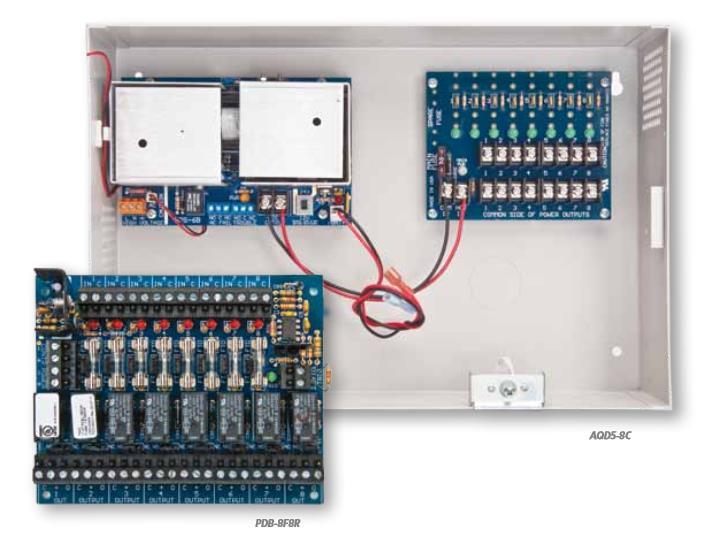
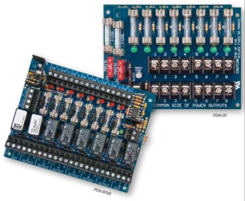
22 Other Boards Distribution Relays Outputs Relays Fire Relays Auto Releases Fuses or PTC

23 Distribution Boards Multiple Outputs Distinct and Configurable Circuits Fire Relays Limited by Design Vary by Manufacturer


24 Identify types of electronic hardware and how it is configured!
25 Fail Secure Electrified Hardware Switches are used to control a locking device or to signal a monitoring device Each switch has one movable contact, the POLE, and one or more fixed contacts, the THROWS Normally open SWITCH SYMBOL 25


26 Fail Safe Electrified Hardware Switches are used to control a locking device or to signal a monitoring device Each switch has one movable contact, the POLE, and one or more fixed contacts, the THROWS Normally closed SWITCH SYMBOL 26


27 And all the Switches! And Many More


28 Plenum verses NonPlenum Wire and Distances VERIFY with Mechanical or GC!


29 Common and Smart Devices Common Switch requires human interaction! Smart Switch requires power to work! What comes in NC. What comes in NO. Push Button COM 1 NC 1 COM 2 NO 2 What goes out NC. What goes out NO. DK12 What goes out NC. NC coming in. C What goes out NO. NO throw coming in. REX coming in. coming in. Going out. Are there wires attached?


30 What do you get from the manufactures? If a manufacturer attaches a wire they will tell you what it represents! If a manufacturer does not attach a wire they tell what each location is used for.
31 And we are now ready to select our PS?
32 Break Time 10 Minutes
33 BASIC QUESTIONS TO FIGURE OUT THE PARTS: 1) Devices on circuit what is the load? a) Hardware b) Switches 2) Wire type and gauge based on a distance circuit? a) Plenum b) NonPlenum 3) What is PS capable of for output per circuit? a) Volts & Amps b) Output(s) 4) How big of a power supply do I need? a) Spare power b) Distribution 33
34 Contact Types A NC contact means that the circuit is closed and voltage is transferred from contact to contact in the normal state. Used for Fail Safe locks Form B Contact C NC A NO contact means that the circuit is open and voltage is not transferred from contact to contact in the normal state. Used for Fail Secure locks Form A Contact C NO
35 SPST Switches SPST Normally Closed C NC SPST Normally Open C NO Switches that have one input and just one output (NO or NC) are called single polesingle throw (SPST).
36 SPDT Switches NC C NO Form C Contact Switches with one input and two outputs are called single poledouble throw (SPDT).
37 DPST Switches NC1 C1 C2 NO2 Switches with two input commons and one output for each are called double polesingle throw (DPST).

38 DPDT Switches NC1 C1 C2 NO1 NC2 NO2 Switches with two inputs and two outputs for each are called double poledouble throw (DPDT).
39 Parallel Switch Wiring Normally Open Circuit Multiple NO switches are wired in parallel for fail secure locks. Activating any of the NO switches will apply voltage, releasing the lock.
40 Series Switch Wiring Normally Closed Circuit Multiple NC switches wired in series for failsafe lock. Activating any of the NC switches will break power, releasing the lock.
41 Fail Safe Lock Wiring Step 1: Connect all component negatives to the power supply negative. PSP24 PB3ER NC1 COM1 MAGNALOCK Why do we develop steps for wiring?
42 Fail Safe Lock Wiring Step 2: Connect the power supply positive to the pushbutton COM1 and the pushbutton NC1 to the lock positive. PSP24 BW Stripe Black Wht/Red PB3ER NC1 COM1 Red MAGNALOCK Red Black
43 Fail Safe Lock Wiring Step 1: Connect all component negatives to the power supply negative. PSP24 PB3ER NC1 COM1 PB3ER COM1 NC1 MAGNALOCK

44 Fail Safe Lock Wiring Step 2: Connect the power supply positive to the pushbutton COM1, connect the pushbutton NC1 to the next pushbutton COM1, and that pushbutton NC1 to the lock positive. PSP24 BW Stripe Black Wht/Red PB3ER NC1 COM1 Red Wht/Red PB3ER COM1 NC1 Red MAGNALOCK Red Black
45 Fail Secure Lock Wiring Step 1: Connect all component negatives to the power supply negative. PSP24 PB3ER NO2 COM2 Fail Safe Lock
46 Fail Secure Lock Wiring Step 2: Connect the power supply positive to the pushbutton COM2, and the pushbutton NO2 to the lock positive. PSP24 Stripe Black Wht/Blue PB3ER NO2 COM2 Blue Black Fail Secure Lock Purple
47 Fail Secure Lock Wiring Step 1: Connect all component negatives to the power supply negative. PB3ER NO2 COM2 PSP24 PB3ER NO2 COM2 Fail Secure Lock
48 Fail Secure Lock Wiring Step 2: Connect the power supply positive to the COM2 of both pushbuttons and the NO2 of both pushbuttons to the lock positive. PB3ER Wht/Blue NO2 COM2 Blue PSP24 BW Stripe Black Wht/Blue PB3ER NO2 COM2 Blue Fail Secure Lock Purple Black
49 Wiring the Circuit Step 1: Type of electronic lock? Step 2: Type of wiring circuit/s? Step 3: Connect all component negatives to the power supply negative. Step 4: Connect your circuit/s? BPS 1 AMP PB3ER DK12 MAGNALOCK COM 1 NC 1 COM 2 NO 2 NC C NO REX
50 Fail Safe Lock Wiring Step 2: Connect all smart switch positives to the power supply positive. BPS 1 AMP PB3ER DK12 MAGNALOCK COM 1 NC 1 COM 2 NO 2 NC C NO REX
51 Fail Safe Lock Wiring Step 3: Connect the power supply positive to the pushbutton COM1, connect the pushbutton NC1 to the keypad common, and the lock positive to the keypad normally closed. BPS 1 AMP PB3ER DK12 MAGNALOCK COM 1 NC 1 COM 2 NO 2 NC C NO REX


52 R.E.X. Functions What is the R.E.X. function? The R.E.X. function allows you to use the access devices internal timer to release the lock from devices other than the access device.
53 Fail Safe Wiring With R.E.X. Step 4: Connect the pushbutton COM2 to the power supply positive, then connect the NO2 of the pushbutton to the keypad REX input. BPS 1 AMP Stripe Black Wht/Red Wht/Blu PB3ER COM 1 NC 1 COM 2 NO 2 Red Blue White Orange Red Black DK12 NC C NO REX Green Red Black MAGNALOCK
54 Fail Safe Lock Wiring with Timer Step 1: Connect all component negatives to the power supply negative. Power Supply Mom. Switch COM 1 NC 1 COM 2 NO 2 Mom. Switch NC 1 COM 1 COM 2 NO 2 TM9 Timer C NC NO TRIG Fail Safe Lock MODEL TM9 TIMEMATE Sparks, NV (702)
55 Fail Safe Lock Wiring with Timer Step 2: Connect all smart switch positives to the power supply positive. Power Supply Mom. Switch COM 1 NC 1 COM 2 NO 2 Mom. Switch NC 1 COM 1 COM 2 NO 2 TM9 Timer C NC NO TRIG Fail Safe Lock MODEL TM9 TIMEMATE Sparks, NV (702)
56 Fail Safe Lock Wiring with Timer Step 3: Connect the power supply positive to the pushbutton COM1, connect the pushbutton NC1 to the timer common, and the timer normally closed to the lock positive. Power Supply Mom. Switch COM 1 NC 1 COM 2 NO 2 Mom. Switch NC 1 COM 1 COM 2 NO 2 TM9 Timer C NC NO TRIG Fail Safe Lock MODEL TM9 TIMEMATE Sparks, NV (702)
57 Fail Safe Lock Wiring with Timer Step 4: Connect the pushbutton COM 2 to the power supply positive, then connect the normally open of the pushbutton to the timer trigger input. Power Supply Stripe Black Wht/Red Mom. Switch Wht/ Blu COM 1 NC 1 COM 2 NO 2 Wht/Red Red Blue Wht/Blu Mom. Switch NC 1 COM 1 COM 2 NO 2 Red Blue White Yellow Red Black TM9 Timer C NC NO TRIG Green Fail Safe Lock Red Black MODEL TM9 TIMEMATE Sparks, NV (702) REMINDER Parallel Circuits ALL COMMONS MUST TOUCH POSITIVE! ALL THROWS MUST TOUCH THE NEXT DEVICE IN!
58 Fail Secure Wiring With R.E.X. Step 1: Connect all component negatives to the power supply negative. BPS 1 AMP PB3ER COM2 COM1 NC1 DK12 NC C NO Fail Secure Lock NO2 REX
59 Fail Secure Wiring With R.E.X. Step 2: Connect all smart switch positives to the power supply positive. BPS 1 AMP PB3ER COM2 COM1 NC1 DK12 NC C NO Fail Secure Lock NO2 REX
60 Fail Secure Wiring With R.E.X. Step 3: Connect the COM2 of the pushbutton to the power supply positive or keypad SRC then the C of the keypad to the power supply positive, and the lock positive to the NO of the keypad. BPS 1 AMP PB3ER DK12 Fail Secure Lock COM2 COM1 NC C NC1 NO NO2 REX
61 Fail Secure Wiring With R.E.X. Step 4: Connect the pushbutton NO2 to the keypad REX input. BPS 1 AMP Stripe Black Wht/Blu PB3ER COM2 COM1 NC1 NO2 Blue White Orn Red Black DK12 NC C NO REX Blue Fail Secure Lock Purple Black
62 Fail Secure Lock Wiring with Timer Step 1: Connect all component negatives to the power supply negative. Power Supply Mom. Switch TM9 Timer Fail Secure Lock COM2 COM1 C NO NC1 NC NO2 TRIG MODEL TM9 TIMEMATE Sparks, NV (702)
63 Fail Secure Lock Wiring with Timer Step 2: Connect all smart switch positives to the power supply positive. Power Supply Mom. Switch TM9 Timer Fail Secure Lock COM2 COM1 C NO NC1 NC NO2 TRIG MODEL TM9 TIMEMATE Sparks, NV (702)
64 Fail Secure Lock Wiring with Timer Step 3: Connect the power supply positive to the pushbutton COM2 and TM9 common, connect the timer normally open to the lock positive. Power Supply Mom. Switch COM2 COM1 NC1 NO2 TM9 Timer C NO NC TRIG Fail Secure Lock MODEL TM9 TIMEMATE Sparks, NV (702)
65 Fail Secure Lock Wiring with Timer Step 4: Connect the pushbutton NO2 to the timer trigger input. Power Supply Stripe Black Wht/Blu Mom. Switch COM2 COM1 NC1 NO2 Blue White Yellow Red Black TM9 Timer C NO NC TRIG Blue Fail Secure Lock Purple Black MODEL TM9 TIMEMATE Sparks, NV (702) REMINDER Parallel Circuits ALL COMMONS MUST TOUCH POSITIVE! ALL THROWS MUST TOUCH THE NEXT DEVICE IN!


66 THE PATH Wire Pics of Shielded or Unshielded Solid or Stranded PVC Jacket or Plenum 67

67 Circuit Layout Device Current Draw On Circuit. M62 EEB2 XMS DK26 Total 150mA 50mA 50mA 190mA 440mA M62 Current Draw 150 ma XMS Current Draw 50mA DK26/KP Current Draw 20mA 190mA 25% 250mA 690mA Minimum output from circuit should be at least 700 ma Before determining the wire run length. EEB2 Current Draw 50mA
68 We Design the circuit from the furthest point in! F/A Mag 150mA 2 Cond. 18 AWG 15 ft. 4 Cond. 18 AWG 10 ft. 4 cond. 18 awg. 100 ft. DK26 170mA 75mA PIR AQD6 8F8R 6A 1250 ma EEB2 6 Cond. 18 AWG 15 ft. 125 ma 6 Cond. 18 AWG 15 ft.
69 Sizing a Power Source Starts with the Circuit Add up amperage of all components & add 25% more ma Example: Example: Strike 250mA M32 Maglock 150mA DK12 40mA Keypad 70mA Wire 125mA 415mA PIR Wire 18 Guage wire resistance = 1.6 vdc drop over 1000 ft (.250 x 6.4) = 1.6voltage drop 120mA 125mA 465mA 24vdc 1.6 = 22.4 vdc 1 Door per Circuit minimum amp on circuit If both doors on the same circuit minimum amp


70 Wire Voltage Drop To calculate the wire resistance, you need to know the distance from the power supply to the lock and the gauge of the wire. This chart shows wire resistance for copper wire per 1,000 ft
71 ELECTRIFIED HARDWARE
 = the Vdc dropped across the full length of the wire..12 X 2.5 =.6 voltage drop across the wire Strike requirement is 24 Vdc ±10% (±1.2Vdc) or xx.x low and xx.x high, but.")
72 Wire Voltage Drop Take the current draw of the lock and multiply by the resistance of the wire I X R = Voltage drop. An HES 5000 series strike requires.12 amp for 24 Vdc operation X 2.5 Ohms (14 gauge / 200 ft) = the Vdc dropped across the full length of the wire..12 X 2.5 =.6 voltage drop across the wire Strike requirement is 24 Vdc ±10% (±1.2Vdc) or xx.x low and xx.x high, but.3 amps require for inrush to open the keeper Vdc.6 Vdc = 11.4 Vdc delivered to the strike.3 amp load needed by the strike X 2 for safety =.6 amps so a 1 amp power supply will be sufficient to run the strike with power to spare.
73 Creating the Circuit! WIRING DIAGRAM Systems Wiring Diagram or Point to Point Wiring Diagram 120VAC Transformer Pushbutton PUSH TO EXIT UnLocked Electric Strike Nonpolarized C NC NO Rectifier AC Side DC Side 74
74 ELECTRIFIED HARDWARE Elements of a System ONE HARDWARE LIST THREE SYSTEM WIRING DIAGRAM OPERATIONS NARRATIVE TWO ELEVATION DRAWING FOUR 75
75 ELECTRIFIED HARDWARE 1. OPERATIONS NARRATIVE 3. ELEVATION DRAWING 2. HARDWARE LIST 4. WIRING DIAGRAM REQUIREMENTS Outside Operation At Rest (while locked) Electrically Unlock Mechanically Unlock Power Failure LED s Inside Operation Required in Specifications and Submittals 76
76 ELECTRIFIED HARDWARE 1. OPERATIONS NARRATIVE 3. ELEVATION DRAWING 2. HARDWARE LIST 4. WIRING DIAGRAM Door shall be closed and secure at all times. Entry by valid code in keypad. Electric strike will relock in 5 seconds. Outside trim has key override for emergency entry. Outside trim shall remain locked with loss of power Inside always free for immediate egress. Required in Specifications and Submittals 77
77 ELECTRIFIED HARDWARE 1. OPERATIONS NARRATIVE 3. ELEVATION DRAWING 2. HARDWARE LIST 4. WIRING DIAGRAM 1. Power Supply 2 Key Pad 3. Electric Strike Required in Specifications and Submittals 78
78 ELECTRIFIED HARDWARE Power Supply 120VAC input 1. OPERATIONS NARRATIVE 3. ELEVATION DRAWING 2. HARDWARE LIST 4. WIRING DIAGRAM Key Pad Electric Strike Not required in Specifications Required in Submittals 79

79 ELECTRIFIED HARDWARE 1. OPERATIONS NARRATIVE 2. HARDWARE LIST 3. ELEVATION DRAWING 4. WIRING DIAGRAM Not required in Specifications Required in Submittals 80

80 Riser diagrams 120 VAC INPUT TRANSFORMER 2 CONDUCTOR 2 CONDUCTOR PUSH BUTTON ¾ 24VAC ELECTRIC STRIKE Wiring diagrams Operations narratives Door is normally closed, latched and secure from the outside. Depressing the push switch will unlock the electric strike to allow ingress. The strike will stay unlocked until depressing the push button the second time. The electric strike will be locked during a power failure. Free egress is allowed at all times.
81 INSTRUCTIONS SYSTEM 1 Fail Secure, DC System Page No. Hardware List Mfg. Product No. Electric strike hes V Momentary pushbutton Securitron PB5 Power supply Securitron AQD6 Buzzer Securitron PZ1 Wiring diagram Operating Instructions: Push button to unlock strike and sound a buzzer to indicate strike unlocked. Student Instructions 1. Write an operations narrative 2. Draw an elevation diagram 3. Complete the point to point wiring diagram 4. Wire the basic circuit 5. Have instructor check wiring before applying power 6. Plug in power supply
82 Buzzer NARRATIVE/RISER DIAGRAM SYSTEM 1 Fail Secure, DC System Page No. Hardware List Electric strike (xxxx24v) Mom. pushbutton (PB5) Power supply (BPS242) Buzzer (PZ1) Ceiling line 218AWG 218AWG 24VDC out 24VDC out Power Supply 120VAC EXERCISE NO. 1 Operations Narrative: Door is normally closed latched and secure from outside Depressing pushbutton will unlock strike and buzzer will sound. Pushbutton located at receptions desk Releasing pushbutton will relock strike and shunt buzzer. Mechanical key override from outside at all times. During a power failure or fire alarm activation strike will be locked Free egress from inside at all times Finished floor
83 24 VDC Positive Outputs 24 VDC Negative Outputs Fi r e Al a r m C o n t a c t s WIRING DIAGRAM SYSTEM 1 Fail Secure, DC System Page No. Hardware List Electric strike (500024V) Mom. Pushbutton (PB5) Power supply (AQD6 24v) Buzzer (PZ1) R1 H N G 120VAC input UnLocked Electric Strike NC PUSH TO EXIT C P1 F1 FA F2 H NO 24v Buzzer
84 24 VDC Positive Outputs 24 VDC Negative Outputs Fi r e Al a r m C o n t a c t s WIRING DIAGRAM SYSTEM 1 Fail Secure, DC System Page No. Hardware List Electric strike (830024V) Mom. pushbutton (PB5) Buzzer (PZ1) Power supply (BPS242) R1 H N G 120VAC input Locked Electric Strike NC PUSH TO EXIT C P1 F1 FA F2 H NO 24v Buzzer
 Buzzer (ZP1) Timer (TM9) Power supply (BPS242) Ceiling line 218AWG 218AWG 24VDC out 24VDC out Power Supply X Timer 120VAC EXERCISE NO.")
85 Buzzer NARRATIVE/RISER DIAGRAM SYSTEM 2 Fail Secure, DC System x timer Page No. Hardware List Electric strike (830024V) Mom. pushbutton (PB5) Buzzer (ZP1) Timer (TM9) Power supply (BPS242) Ceiling line 218AWG 218AWG 24VDC out 24VDC out Power Supply X Timer 120VAC EXERCISE NO. 2 Operations Narrative: Door is normally closed latched and secure from outside Depressing and releasing pushbutton will unlock strike and sound buzzer for 5 seconds, automatically relocking and shunting buzzer Pushbutton located at receptions desk Mechanical key override from outside at all times. During a power failure or fire alarm activation strike will be locked Free egress from inside at all times Finished floor
86 24 VDC Positive Outputs 24 VDC Negative Outputs Fi r e Al a r m C o n t a c t s To NC Fire Alarm contacts WIRING DIAGRAM SYSTEM 2 Fail Secure, DC System, timer Page No. Hardware List Electric strike (xxxx24v) Mom. pushbutton (PB5) Buzzer (ZP1) Timer (TM9) Power supply (ADQ6 24v) R1 R2 R3 R4 H N G 120VAC input UnLocked PUSH TO EXIT P1 P2 F1 FA Electric Strike NC C P3 P4 F2 H NO 24v BLUE (REL. N.O.) Buzzer GREEN (REL. N.C.) WHITE (REL.COM) YELLOW (TRIGGER) RED (v OR AC IN) TM9 Timemate ON BLACK (NEG OR AC IN)
 LED s (ZLP1) Door position switch Power supply (AQD6246) Wiring diagram Ceiling line 318AWG 218AWG 24VDC out 24VDC out 218AWG Power Supply 120VAC Operations")
87 NARRATIVE/RISER DIAGRAM SYSTEM 3 Monitor Strike x LED s and DPS Page No. Hardware List Monitor strike (LML1) LED s (ZLP1) Door position switch Power supply (AQD6246) Wiring diagram Ceiling line 318AWG 218AWG 24VDC out 24VDC out 218AWG Power Supply 120VAC Operations Narrative: Door is normally closed, latched and secure all times Mechanical key entry at all times. During a power failure door remains secure and LED s not illuminated. Red LED, door closed and latched. Green LED, door opened and latch disengaged from strike Free egress from inside at all times LED s located at security panel EXERCISE NO. 3 Finished floor
88 24 VDC Positive Outputs 24 VDC Negative Outputs Fi r e Al a r m C o n t a c t s To NC Fire Alarm contacts WIRING DIAGRAM SYSTEM 3 Monitor Strike x LED s and DPS Page No. Hardware List Monitor strike (LML1) LED s (ZLP1) Door position switch Power supply (BPS242) Monitor strike (Shown Tripped with latch engaged) R1 R2 R3 H N G 120VAC input LED s NC C R4 P1 F1 RED NO P2 P3 FA F2 P4 H 242 GREEN C NC White Red NO
89 24 VDC Positive Outputs 24 VDC Negative Outputs Fi r e Al a r m C o n t a c t s To NC Fire Alarm contacts WIRING DIAGRAM SYSTEM 3 Hardware List Monitor Strike x LED s and DPS Page No. Monitor strike (LML1) LED s (ZLP1) Door position switch Power supply (BPS242) Monitor strike (Shown Tripped with latch engaged) R1 R2 R3 H N G 120VAC input LED s NC C R4 P1 F1 RED NO P2 P3 FA F2 P4 H 242 GREEN C NC White Red NO
90 24 VDC Positive Outputs 24 VDC Negative Outputs Fi r e Al a r m C o n t a c t s To NC Fire Alarm contacts WIRING DIAGRAM SYSTEM 3 Monitor Strike x LED s and DPS Page No. Hardware List Monitor strike (LML1) LED s (ZLP1) Door position switch Power supply (BPS242) Monitor strike (Shown Tripped with latch engaged) R1 R2 R3 H N G 120VAC input LED s NC C R4 P1 F1 RED NO P2 P3 FA F2 P4 H 242 GREEN C NC White Red NO
91 24 VDC Positive Outputs 24 VDC Negative Outputs Fi r e Al a r m C o n t a c t s To NC Fire Alarm contacts WIRING DIAGRAM SYSTEM 3 Monitor Strike x LED s and DPS Page No. Hardware List Monitor strike (LML1) LED s (ZLP1) Door position switch Power supply (BPS242) Monitor strike (Shown Tripped with latch engaged) R1 R2 R3 H N G 120VAC input LED s NC C R4 P1 F1 RED NO P2 P3 FA F2 P4 H 242 GREEN NC Red C White NO
92 INSTRUCTIONS SYSTEM 4 Latch Retraction by Keypad Page No. Hardware List Mfg. Product No. Power transfer hinge McKinney TA2714 x 41/2 x 41/2 x QC8 Exit Device Sargent F x 24VDC Digital keypad Securitron DK12 x 24VDC Digital timer Securitron DT7 x 24VDC Power supply Securitron BPS242 Wiring diagram Operating instructions: Connect the components so that latchbolt retracts and projects automatically at a certain time. Keypad to only operate when latchbolt is projected. Student instructions 1. Write an operations narrative 2. Draw an elevation diagram 3. Complete the point to point wiring diagram 4. Wire the basic circuit 5. Have instructor check wiring before applying power 6. Plug in power supply
 Digital keypad (DK12) Digital timer (DT7) Power supply (BPS242) Wiring Diagram Ceiling line 120VAC 418AWG Power Supply x timer 218AWG")
93 NARRATIVE/RISER DIAGRAM SYSTEM 4 Latch Retraction by Keypad Page No. Hardware List Power transfer hinge Exit Device (latch retraction) Digital keypad (DK12) Digital timer (DT7) Power supply (BPS242) Wiring Diagram Ceiling line 120VAC 418AWG Power Supply x timer 218AWG Operations Narrative: EXERCISE NO. 4 During business hours (8:00am 5:00pm) latchbolt will be retracted and door is push pull. After hours latchbolt automatically projects and secures door. Keypad mounted 42 ABF C L Entering valid numerical code will retract latchbolt for 5 seconds and then automatically release Mechanical key override from secure side at all times During a power failure or fire alarm activation door will remain secure Free egress from inside at all times Finished floor
94 24 VDC Positive Outputs 24 VDC Negative Outputs Fi r e Al a r m C o n t a c t s To NC Fire Alarm contacts WIRING DIAGRAM SYSTEM 4 Latch Retraction by Keypad Page No. Hardware List Power transfer hinge Exit device (568810) Digital keypad (DK12) Digital timer (DT7) Power supply (BPS242) R1 R2 R3 R4 H N G 120VAC input P1 F1 P2 FA P3 F2 Red Black Green Pink Tan REX NO P4 H 242 DK C 5 * 0 # NC 6
95 24 VDC Positive Outputs 24 VDC Negative Outputs Fi r e Al a r m C o n t a c t s To NC Fire Alarm contacts WIRING DIAGRAM SYSTEM 4 Latch Retraction by Keypad Page No. Hardware List Power transfer hinge Exit device (568810) Digital keypad (DK12) Digital timer (DT7 Power supply (BPS242) R1 R2 R3 R4 H N G 120VAC input P1 P2 P3 F1 FA F2 Red Black Green Pink Tan REX Wiring REX NO C P4 H 242 DK * 0 # NC 6
96 INSTRUCTIONS SYSTEM 5 Fail safe, mortise lock x keypad Page No. Hardware List Mfg. Product No. Power transfer hinge McKinney TA2714 x 41/2 x 41/2 x QC8 Mortise lock CR, Sargent, Yale ML20905, 8270, 8890FL x 24VDC Digital keypad Securitron DK12 x 24VDC Alt. keyswitch Securitron MKA Power supply Securitron BPS 242 Wiring diagram Operating Instructions: Connect the components so that entering a code will unlock the lock for 5 seconds and relock. A keyswitch to turn system on and off. Student Instructions 1. Write an operations narrative 2. Draw an elevation diagram 3. Complete the point to point wiring diagram 4. Wire the basic circuit 5. Have instructor check wiring before applying power 6. Plug in power supply
 Power supply (BPS 242) Ceiling line 218AWG 120VAC 318AWG Power Supply 218AWG Operations Narrative: C L EXERCISE NO.")
97 NARRATIVE/RISER DIAGRAM SYSTEM 5 Fail safe, mortise lock x keypad Page No. Hardware List Power transfer hinge Mortise lock (fail safe) Digital keypad (DK12) Alt. keyswitch (MKA2) Power supply (BPS 242) Ceiling line 218AWG 120VAC 318AWG Power Supply 218AWG Operations Narrative: C L EXERCISE NO. 5 Door is normally closed latched and secure from outside Entering valid numerical code will unlock the lock for 5 seconds and automatically relock C L Mechanical key override from outside at all times 72 AFF 42 AFF During a power failure or fire alarm activation lock will be unlocked Authorized key in keyswitch will turn system on and off Free egress from inside at all times Finished floor
98 24 VDC Positive Outputs 24 VDC Negative Outputs Fi r e Al a r m C o n t a c t s To NC Fire Alarm contacts WIRING DIAGRAM SYSTEM 5 Fail safe, mortise lock x keypad Page No. Hardware List Power transfer hinge Mortise lock (fail safe) Digital keypad (DK12) Alt. keyswitch (MKA2) Power supply (BPS242) R1 R2 R3 R4 H N G 120VAC input P1 F1 C NC P2 P3 FA F2 NO P4 H 242 REX NO DK BLACK RED C NC 5 6 * 0 #
99 24 VDC Positive Outputs 24 VDC Negative Outputs Fi r e Al a r m C o n t a c t s To NC Fire Alarm contacts WIRING DIAGRAM SYSTEM 5 Fail safe, mortise lock x keypad Page No. Hardware List Power transfer hinge Mortise lock (fail safe) Digital keypad (DK12) Alt. keyswitch (MKA2) Power supply (BPS242) R1 R2 R3 R4 H N G 120VAC input P1 F1 C NC P2 P3 FA F2 NO P4 H 242 REX NO DK BLACK RED C NC 5 6 * 0 #
100 Break Time 10 Minutes
101 And we are now ready to select our PS?


102 Types of Power Supplies Plugin Transformers Plugin Power Supplies Hardwired Power Supplies Fire alarm interface Battery charging Power supply monitors 103
103 Linear verses Switching Power Linear : Block transformer (steel or iron) decreases voltage by burning off heat! Old School Switching: Steps down power through diodes and capacitors to smooth out and drop voltage, reducing noise! 2017 Switching: Steps down power through diodes and capacitors to smooth out and drop voltage, reducing noise!
104 Linear Switching Linear Power Dominant until 1970 s Switch Mode Available in 1970 s Now : Consumer Products, Toys, Cell, etc. Diodes & capacitors smooth in high voltage DC. Uses diodes & capacitors for smoothing out voltage Quieter Approx. 60% efficiency DC converted to low voltage by small ferrite xtrmr and FET s or transistors. Reliability Higher Conversion required for use outside the US Does not tolerate small losses of power can cause major issues Handles voltage load changes better Voltage is converted into DC output by another set of diodes and capacitors & inductors. Approx. 96% efficiency Reliability Lower Operate almost worldwide Tolerates small power losses
105 What do you order? Call your favorite distributor! Ask for 12/24 Volt AC/DC Power Supply and Amps needed Which PS do you normally get and why? They give you a PS Rated at 6 Amps at 12 Volts DC Convert to 24 VDC what happens to Amps? Some systems convert to 50% of original amperage? 6 Amps now becomes 3 Amps Does the Power Supply use amperage to work? Does a distribution board use amperage to work?
106 Older Generation Power Supply Pick your voltage 12/24 Select your Amps Convert from 12 to 24 Reduce your amps in half Ex. 10 amps went to 5 amps* Install Backup Battery Reduces amp output Ex. 1 amp went to 750 ma* Approx. Values *
107 Next Generation Power Supply Pick your voltage 12/24 Select your Amps Convert from 12 to 24 No Reduction in amps Ex. 10 amps went to 5 amps* Install Backup Battery Charging Circuit Separate from output Selecting Fused or PTC
108 Main PS Board Average Voltage Output at 24VDC Will be around 2427 VDC AC Voltage Input DC Voltage Output Voltage Jumper VDC Output Monitor for AC and Battery Fail
109

110 What is the important?


111 Output Boards Different Sizes and functions Fire or NonFire Ratings Fuses verses PTC Universal Verses Separate Control Requires power to work

112 Amazing what the wrong voltage can do to a board.

113 Distribution Board Specifications
114 Fire Alarm Interface Used to release fail safe locks in the event of fire. Needed to meet life safety codes on most electric locking systems. Usually between power supply and fire system. EOL resistor fire alarm interface Is the circuit closed. N/C Contacts N/C Contacts N/O Contacts 2.2K EOL Resistor N/O Contacts 2.2K EOL Resistor Fire Alarm Contacts Fire Alarm Contacts BPS 1 Amp BPS 215 Amp EOL Resistor BPS 1 Amp BPS 215 Amp
115 Our focus today AQD68PCI Fire Alarm Input Relay UL Listed
116 INSTRUCTIONS SYSTEM 5 Fail safe, mortise lock x keypad Page No. Hardware List Mfg. Product No. AQDer transfer hinge McKinney TA2714 x 41/2 x 41/2 x QC8 Mortise lock CR, Sargent, Yale ML20905, 8270, 8890FL x 24VDC Digital keypad Securitron DK12 x 24VDC Alt. keyswitch Securitron MKA Power supply Securitron AQD6 Wiring diagram Operating Instructions: Connect the components so that entering a code will unlock the lock for 5 seconds and relock. A keyswitch to turn system on and off. Student Instructions 1. Write an operations narrative 2. Draw an elevation diagram 3. Complete the point to point wiring diagram 4. Wire the basic circuit 5. Have instructor check wiring before applying power 6. Plug in power supply
117 Project Time


118 Invest in training HES Electric Strike Applications & Installation Securitron State of the Art Smart Product Applications Access Control Hardware Selection Basic Low Voltage Electricity for Installers Advanced Electronic System Wiring & Troubleshooting Site Survey & Magnetic Lock System Installation Adams Rite Storefront Products Mechanical to Electronic NEW COURSES IN DEVELOPMENT: EMS Product Troubleshooting Aperio Product and Applications DKC Access Control Wiring & Configuration Advanced Technical Product Troubleshooting 119


119 Technical Support 10 Minute Rule Rodger Schmidt MAGLOCK

120 Rodger Schmidt Product Trainer ASSA ABLOY HES/Securitron/Adams Rite Phoenix, AZ

121 Thanks for a Shockingly good time

122
123 Level 3 Electric Power, Circuits and Systems

124
Electronic Locking Hardware Codes. Rodger Schmidt ASSA ABLOY EMSO Group HES/Folger Adams/Securitron/Adams Rite/Alarm Controls
 Electronic Locking Hardware Codes Rodger Schmidt ASSA ABLOY EMSO Group HES/Folger Adams/Securitron/Adams Rite/Alarm Controls 2 Rodger Schmidt ASAA ABLOY Americas Welcome & Introductions 22+ years of Security,
Power Transfer Devices. Access Control Accessories. How To Order. How to Order
 Power Transfer Devices Door Cord (TSB-C) Simplest and most economical solution for power transfer Standard with Touch Sense Bar and MGL but may also be purchased separately Consists of an 18 [460mm] or
Security Professional Mobile Showroom. Product Training
 Security Professional Mobile Showroom Product Training Benefits of the Showroom Benefits of the Security Professional Showroom Are: Bringing Full Line of Solutions to You Tours for you Technicians and
Power Supplies. Overview
 Power Supplies Overview Access control provides enhanced security, audit trails, and custom credentials. The power supply is necessary to make the entire system operational. Power supplies offer accurate
Mechanical to Electrical Making the Jump
 Mechanical to Electrical Making the Jump 1 Making the move to electrified openings doesn t have to be scary. Adams Rite makes it easy by offering products for aluminum and glass storefronts that can easily
Securitron Magnalock Corporation S. 51 st St., Ste. 102 Phoenix, AZ Phone: (800) MAGLOCK
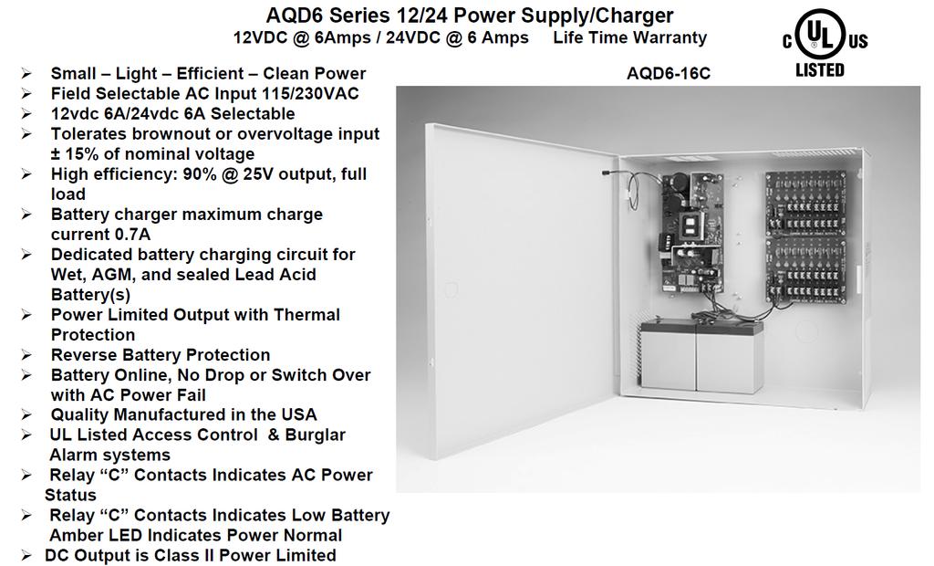
 MAGLOCK") Installation Manual AQM-20 12vdc/24vdc Series Power Supplies AQM20 Supervised Power Supply/Charger 12vdc 20Amp/24vdc 10Amp Life Time Warranty Quality Manufactured in the USA AQM20 Features: The AQM20 has
Installation Manual AQM-20 12vdc/24vdc Series Power Supplies AQM20 Supervised Power Supply/Charger 12vdc 20Amp/24vdc 10Amp Life Time Warranty Quality Manufactured in the USA AQM20 Features: The AQM20 has
Upgrade Your Solution: Mechanical to Electrical
 Upgrade Your Solution: Mechanical to Electrical 2 Upgrading from mechanical to electrified hardware doesn t have to be difficult. Adams Rite makes it easy by offering products for aluminum and glass storefronts
LOCK INTO THE ACSI ADVANTAGE LOCK INTO THE ACSI ADVANTAGE
 LOCK INTO THE ACSI ADVANTAGE LOCK INTO THE ACSI ADVANTAGE MODIFICATIONS TO: ADAMS RITE ARROW CORBIN RUSSWIN DORMA DOROMATIC MONARCH PRECISION SARGENT VON DUPRIN YALE and more SERIES 1500 EXIT DEVICES CATALOG
GATE & Fence. Solar Power Supplies. Gate Locks. Gate Lock Bracket Kits. Specialty Brackets. Power Supplies. And More...
 Solar Power Supplies Gate Locks Gate Lock Bracket Kits Specialty Brackets Power Supplies And More... GATE & Fence Electrified Locking Products and Accessories About Securitron Who We Are... Since 1971,
Mechanical to Electrical Solutions. for Aluminum and Glass Openings
 Mechanical to Electrical Solutions for Aluminum and Glass Openings Making the move to electrified openings doesn t have to be scary. Adams Rite makes it easy by offering products for aluminum and glass
ACM8 Series UL Listed Sub-Assembly Access Power Controllers. Installation Guide. ACM8 - Eight (8) Fuse Protected Outputs
 Fuse Protected Outputs") ACM8 Series UL Listed Sub-Assembly Access Power Controllers Installation Guide Models Include: ACM8 - Eight (8) Fuse Protected Outputs ACM8CB - Eight (8) PTC Protected Outputs Rev. 042811 More than just
ACM8 Series UL Listed Sub-Assembly Access Power Controllers Installation Guide Models Include: ACM8 - Eight (8) Fuse Protected Outputs ACM8CB - Eight (8) PTC Protected Outputs Rev. 042811 More than just
PS6 SERIES. Installation PS6 SERIES. Power Supplies c/w Fire Panel Interface, EOL Trigger and Standby Power Option
 Installation PS6 SERIES Power Supplies PS6 SERIES Power Supplies c/w Fire Panel Interface, EOL Trigger and Standby Power Option Installation and Specifications Manual ISDPS6_SERIES 08121590 PCN15016 R05/15GR
DE5300 Delayed Egress System. General Information
 *911031-00* 911031-00 Wiring and Configuration DE5300 Delayed Egress System Installation Instructions General Information The Von Duprin DE5300 is designed for controlled egress applications when used
1.800.MAGLOCK SECURITRON.COM GATE & FENCE
 1.800.MAGLOCK SECURITRON.COM GATE & FENCE ABOUT SECURITRON As the world s premier supplier of electric locking systems and access control components, Securitron, an ASSA ABLOY Group brand, excels in manufacturing
Remote Chexit Module (RCM) System. General Information
 System. General Information") *911032-00* 911032-00 Wiring and Configuration Remote Chexit Module (RCM) System Installation Instructions General Information The Von Duprin RCM is designed for controlled egress applications. It meets
*911032-00* 911032-00 Wiring and Configuration Remote Chexit Module (RCM) System Installation Instructions General Information The Von Duprin RCM is designed for controlled egress applications. It meets
SECTION DOOR HARDWARE
 McClellan Blakemore Architects New Warehouse Facility for SECTION 08710 DOOR HARDWARE PART 1 GENERAL 1.01 SECTION INCLUDES A. Hardware for wood and hollow steel doors. B. Hardware for fire-rated doors.
APS-300 SERIES DUAL VOLTAGE UL 294 LISTED ACCESS CONTROL POWER SUPPLIES
 APS-300 SERIES DUAL VOLTAGE UL 294 LISTED ACCESS CONTROL POWER SUPPLIES POWER SUPPLY AND BATTERY CHARGER AC AND DC STATUS INDICATORS ENOUGH POWER TO SUPPORT UP TO 3 MAGLOCKS OR ELECTRIC STRIKES PLUS REQUIRED
SP-1000X. Panic Device Power Controller Installation Guide. Rev
 TM SP-1000X Panic Device Power Controller Installation Guide Rev. 120213 Overview: SP-1000X will operate up to two (2) 24VDC panic hardware devices simultaneously. It is designed to handle the high current
Accessories. Desk Top Controls
 Accessories Desk Top Controls 15-2 15-1 15-3 15-2-3 DTMO-1 DTMA-1 Under Desk Top Mounting The SDC 15 series switch controls are mounted on the underside of a desk for remote door control. They may be connected
Installation Guide for models:
 140 58th St. Brooklyn, NY Access Power Controllers with Power Supplies Installation Guide for models: Maximal11F - Power Supply 1: 12VDC @ 3.3 amp or 24VDC @ 3.6 amp. - Power Supply 2: 12VDC @ 3.3 amp
Accessories DESK TOP CONTROLS MODELS SPECIFICATIONS MODELS SPECIFICATIONS UNDER DESK TOP MOUNTING MINI DESK TOP CONSOLE
 Accessories DESK TOP CONTROLS UNDER DESK TOP MOUNTING The SDC 15 Series Switch controls are mounted on the underside of a desk for remote door control. They may be connected to the REX input of an access
Installation Guide for models:
 140 58th St. Brooklyn, NY Access Power Controllers with Power Supplies Installation Guide for models: Maximal3FD - 12VDC @ 4.6 amp or 24VDC @ 5.2 amp. - Sixteen (16) PTC protected power-limited outputs.
ACM8 & ACM8CB. Access Power Controllers Installation Guide. - Fused Outputs - Fused Outputs. - PTC Outputs - PTC Outputs. Models Include: Rev.
 ACM8 & ACM8CB Access Power Controllers Installation Guide Models Include: ACM8 ACM8E - Fused Outputs - Fused Outputs ACM8CBE ACM8CB - PTC Outputs - PTC Outputs Rev. 092503 Overview: These units convert
Retrofit Solutions Upgrading access control from doors to drawers
 Retrofit Solutions Upgrading access control from doors to drawers ASSA ABLOY ELECTRONIC SECURITY HARDWARE & SECURITRON ADAMS RITE ALARM CONTROLS MEDECO Executive Office Hollow Metal or Wood Conference
KT-100 Door Controller
 WARNING: This manual contains information on limitations regarding product use and function and information on the limitations as to liability of the manufacturer. The entire manual should be carefully
Series. Access Power Controllers. Installation Guide
 Series Access Power Controllers Installation Guide Models Include: Maxim11 - Power Supply 1: 12VDC @ 3.5 amp or 24VDC @ 2.7 amp. - Power Supply 2: 12VDC @ 3.5 amp or 24VDC @ 2.7 amp. - Sixteen (16) fuse
ACSI AO ELECTRIC LATCH RETRACTION CONTROLLER INSTALLATION INSTRUCTIONS I.D. 1089, REV. F
 II 1400-2 ACSI 1406-04-AO ELECTRIC LATCH RETRACTION CONTROLLER INSTALLATION INSTRUCTIONS I.D. 1089, REV. F INSTALLATION Transformer Model BE31763001 by Basler Electric, Transformer Model 2010028 by Galaxy
Accessories. Desk Controls. Break Glass Emergency Door Release SECURITY DOOR CONTROLS
 Accessories Desk Controls 15-2 15-1 15-3 15-2-3 DTMO-1 DTMA-1 Under Desk Top Mounting 15-1 On-Off Push Switch 15-2 Momentary Push Switch 15-3 On-Off Toggle Switch 15-2-3 On-Off Toggle Switch and Momentary
ACM4 Series UL Listed Sub-Assembly Access Power Controllers
 ACM4 Series UL Listed Sub-Assembly Access Power Controllers Installation Guide Models Include: ACM4 - Four (4) Fuse Protected Outputs ACM4CB - Four (4) PTC Protected Outputs Rev. 051311 More than just
PLEASE READ ALL INSTRUCTIONS PRIOR TO INSTALLING THE SYSTEM. HANDLE THE EQUIPMENT CAREFULLY.
 575 Birch Street, Forestville, CT 06010 Phone (866) 322-1237 Fax (866) 322-1233 WWW.LOCKNETICS. CL-CONTROLLER CL-CONTROLLER UNLIMITED USERS ALLOWED 2000 AUDIT EVENTS SOFTWARE-MANAGED TIME ZONES SOFTWARE-MANAGED
Installation Instructions. PS902 Power Supply. These instructions cover the following parts: PS902 Power Supply Specifi cations:
 F1! 44487023 These instructions cover the following parts: PS902 Power Supply Installation Instructions! DANGER: To avoid risk of electric shock, turn off AC power before installing or servicing PS902
RDM LOCK G Series Electromagnetic Lock. Listings. Standard Features. Ordering Information:
 RDM LOCK G-1 1400 Series Electromagnetic Lock The patented 1400 Series Electromagnetic Lock is universal for all types of applications, including outdoor use. The innovative design will reduce installation
Egress Devices for Code Compliant Access-Controlled Egress Doors
 P.O. Box 6219, Westlake Village, CA 91359-6219 3580 Willow Lane, Westlake Village, CA 91361-4921 (805) 494-0622 (800) 413-8783 Fax: (805) 494-8861 Email: service@sdcsecurity.com www.sdcsecurity.com 400M
For a red enclosure add an R suffix to the part # e.g. eflow4na8dr. Altronix Corp th St. Brooklyn, NY. Installing Company: Service Rep.
 Power Supply/Chargers Installation Guide Models Include: eflow4na8d - 4A @ 12VDC or 24VDC - Eight (8) PTC Outputs eflow6na8d - 4A @ 12VDC or 24VDC - Eight (8) PTC Outputs eflow102na8d - 10A @ 12VDC - Eight
PDD-8PCI. Power Distribution Board With Supervised Interface. Installation and Specifications Manual
 INSTALLATION PDD-8PCI PDD-8PCI Power Distribution Board With Supervised Interface Installation and Specifications Manual Details The PDD-8PCI board is a power distribution/control interface. This board
120 VOLT POTENTIAL PRESENT. MAKE SURE POWER INPUT TO UNIT IS TURNED OFF DURING INSTALLATION AND WIRING PROCEDURE.
 00000 (0) 00 PowerMatic Low Energy Power Operator Wiring Instructions 0 VOLT POTENTIAL PRESENT. MAKE SURE POWER INPUT TO UNIT IS TURNED OFF DURING INSTALLATION AND WIRING PROCEDURE. REQUIREMENTS: U.L.
AL400ULACM AL600ULACM - 4 amp - 12VDC or 6 amp. - Fused Outputs - Fused Outputs
 ACM Series Access Power Controllers with Power Supplies Installation Guide Models Include: AL400ULACM AL600ULACM - 12VDC @ 4 amp - 12VDC or 24VDC @ 6 amp. or 24VDC @ 3 amp - Fused Outputs - Fused Outputs
HARDwired Installation/ Owner s Manual
 HARDwired Installation/ Owner s Manual Use this manual for circuit - Revision L or higher. For Models:,, and Multi-Door Access Controller Wiegand Compatable --R-- Provides Access Control System to manage
System components portfolio overview. Power supplies, electromagnetic locks, electric strikes and system accessories
 System components portfolio overview Power supplies, electromagnetic locks, electric strikes and system accessories Our comprehensive commercial portfolio includes everything you need to hang, protect,
705 Emmett Street Bristol, CT DynaLock MODEL 3101C-TJ101 DELAY EGRESS SYSTEM WIRING INSTRUCTIONS
 BASIC SET-UP 1. Remove the Electronics Cover to expose the circuit board assembly. C L C 2. - System Selector Switches The selector switches (S3) which control major system functions are factory set to
POWER TRANSFERS ACCESSORIES EAC. Manufacturer Product Product No. Product Description Item No.
 POWER TRANSFERS 47 Keedex Cord K-DLA K-DLB Keedex 18 Flexible Cord; Product No. K-DLA; 1/4 flexible conduit; use door loops when you need to transfer electrical current from the door frame to the door;
MODEL KP-200 VANDAL RESISTANT & WEATHERPROOF FLUSH MOUNT DIGITAL KEYPAD DESIGNED FOR ACCESS CONTROL APPLICATIONS
 MODEL KP-200 VANDAL RESISTANT & WEATHERPROOF FLUSH MOUNT DIGITAL KEYPAD DESIGNED FOR ACCESS CONTROL APPLICATIONS OPERATES ON 12 OR 24 VOLTS AC/DC, AUTO VOLTAGE SENSING FULLY PROGRAMMABLE FROM THE KEYPAD
For a red enclosure add an R suffix to the part # e.g. eflow4na8r. Altronix Corp th St. Brooklyn, NY. Installing Company: Service Rep.
 Power Supply/Chargers Installation Guide Models Include: eflow4na8-4a @ 12VDC or 24VDC - Eight (8) Fused Outputs eflow6na8-4a @ 12VDC or 24VDC - Eight (8) Fused Outputs eflow102na8-10a @ 12VDC - Eight
B. After installation, the Owner shall be able to perform hardware configuration changes as desired without the services of the Integrator.
 SECTION 281300 - ACCESS CONTROL SYSTEM PART 1 - GENERAL 1.1 SUMMARY A. Section Includes: 1. Minimum standards for Access Control Systems. B. Related Requirements: 1. Section 087100 Door Hardware. 1.2 REFERENCES
SECURITRON MODEL EXD EXIT DELAY SYSTEMS INSTALLATION AND OPERATING INSTRUCTIONS 1. DESCRIPTION
 PN# h 500-13350 Page 1 Rev. A.3, 7/03 SECURITRON MODEL EXD EXIT DELAY SYSTEMS INSTALLATION AND OPERATING INSTRUCTIONS 1. DESCRIPTION Securitron s EXD series is modular delayed exit locking systems intended
Aperio Technology. Wireless possibilities for online access control
 Aperio Technology Wireless possibilities for online access control Aperio (Latin) / a'pe.ri.o/ to uncover, open Designed for easy integration into existing access control systems, the wide range of Aperio-enabled
/ How To Order
 84-800 / 85-800 How To Order SERIES 84 = 1.0A continuous (powers and controls 1 EExER device with signal output for 1 operator) 85 = 2.0A continuous (powers and controls EExER device for 1 pair of doors
APPENDIX F: LOCKSETS AND ACCESS CONTROL
 APPENDIX F: LOCKSETS AND ACCESS CONTROL F.1 LOCKSETS The University, with the exception of the Housing Division which uses a Best 7-pin system, utilizes a Corbin Russwin 7-pin IC Core keying system. Locksets
UNC100 Integra Manual
 UNC100 Integra Manual New Generation Building Security July 30, 2014 V1.2 Copyright Notice Copyright 1995-2014 by All rights reserved Worldwide. Printed in Canada. This publication has been provided pursuant
RMS/RPX Reader. User Manual
 RMS/RPX Reader User Manual Copyright Disclaimer Trademarks and patents Intended use FCC compliance Copyright 2005, GE Security Inc. All rights reserved. This document may not be copied or otherwise reproduced,
RPSMLR2 RPSMLR2BB. Panic Device Power Controller Installation Guide LISTED. Rev
 RPSMLR2 RPSMLR2BB Panic Device Power Controller Installation Guide LISTED Rev. 102715 Overview: RPSMLR2BB, RPSMLR2 will operate up to two (2) 24VDC panic hardware devices simultaneously. It is designed
Accessories. Desk Controls. Break Glass Emergency Door Release SECURITY DOOR CONTROLS
 Accessories Desk Controls 15-2 15-1 15-3 15-2-3 DTMO-1 DTMA-1 Under Desk Top Mounting 15-1 On-Off Push Switch 15-2 Momentary Push Switch 15-3 On-Off Toggle Switch 15-2-3 On-Off Toggle Switch and Momentary
Exit Switches SECURITY DOOR CONTROLS. 400 Series 410 & 420 Series. Finishes. Finishes. Options. Options. Specifications.
 Exit Switches 400 Series 410 & 420 Series The SDC 400 series are compact, unobtrusive and contemporary in design making it the perfect choice where esthetics are a priority. Built to last, the 400 series
Installation Guide for AL300ULM. Multi-Output Access Control Power Supply Charger
 Installation Guide for AL300ULM Multi-Output Access Control Power Supply Charger R AL300ULM - Multi-Output Access Control Power Supply/Charger Overview: The AL300ULM multi-output access control power supply/charger
RCR-REX Request-to-Exit Dual Technology Motion Sensor Installation Guide
 RCR-REX Request-to-Exit Dual Technology Motion Sensor Installation Guide Introduction This is the Interlogix RCR-REX Request-to-Exit Dual Technology Motion Sensor Installation Instructions for models RCR-REX-W,
Exit Switches 410 & 420 SERIES MODELS SPECIFICATIONS HOW TO ORDER 1 SPECIFY MODEL 2 SPECIFY FINISHES 3 SPECIFY OPTIONS
 Exit Switches 410 & 420 SERIES The illuminated switch button is two inches square for easy activation and is visually conspicuous. The high impact resistant material stands up to abuse. The PUSH to EXIT
Installation Guide for AL400ULM. Multi-Output Access Control Power Supply Charger
 Installation Guide for AL400ULM Multi-Output Access Control Power Supply Charger R AL400ULM - Multi-Output Access Control Power Supply/Charger Rev. 072500 Overview: The AL400ULM multi-output access control
The system should also be capable of recording events automatically on any compatible DVR and should be able to retrieve recordings based on events.
 0BThe System The Security Management System should be capable of Controlling and Monitoring Access through the doors, Monitor and control Inputs and Outputs, include an Integrated Video Badging, Integrate
HES and Securiton have united as ASSA ABLOY Electronic Security Hardware. Electronic Security Hardware HES Securitron Pricelist 2018
 HES and Securiton have united as ASSA ABLOY Electronic Security Hardware Electronic Security Hardware HES Securitron Pricelist 2018 Effective February 1, 2018 When we come together, great things happen.
System Design and Overview Document
 System Design and Overview Document Power Calculations: This is one the most important tasks when designing your system. You must add up worst case current draw of your system. The power supply contained
STANDARD FEATURES SPECIFICATIONS
 MAG LOCK P/N 300768 STANDARD FEATURES Holding Force: 1500 lbs.(675 Kg.) Easy Installation: Versatile mounting bracket for new and existing doors and frames. Sensor: Built-in Hall effect crystal affected
ACSI MODEL 1410 POWER SUPPLY INSTALLATION INSTRUCTIONS
 II 1400-3 ACSI MODEL 1410 POWER SUPPLY INSTALLATION INSTRUCTIONS Features: For use with doors or groups of doors that must interlock with each other to regulate control of accessing one area from another,
Multi-Output Access Control Power Supply Chargers VDC or 24VDC VDC or 4 24VDC.
 M Series Multi-Output Access Control Power Supply Chargers Installation Guide Models Include: AL300ULM AL400ULM - 2.5 amp @ 12VDC or 24VDC. - 3 amp @ 12VDC or 4 amp @ 24VDC. AL600ULM AL1012ULM - 6 amp
232xt Wiring Diagrams and Specifications SPECIFICATIONS: REV 1.01
 232xt Wiring Diagrams and Specifications Voltage Selection Settings 1 2 3 Wire Xtreme Pad color to color to the wires on Programmer (Red to Red, ect.) ( / Yellow ) Position 12-24VA 15-24VD P5* Position
Securitron. Switching Power Supplies
 Securitron Switching Power Supplies Securitron AccuPower Works Better for The Securitron commitment to excellence continues with our AccuPower Series of switching power supplies the latest addition to
Access Power Controllers with Power Supplies
 Access Power Controllers with Power Supplies Installation Guide Models Include: Maximal11FD - Power Supply 1: 12VDC @ 3.3A or 24VDC @ 3.6A. - Power Supply 2: 12VDC @ 3.3A or 24VDC @ 3.6A. - Sixteen (16)
Multi-Output Access Control Power Supply Charger VDC or 24VDC VDC or 3 24VDC.
 M Series Multi-Output Access Control Power Supply Charger Installation Guide Models Include: AL300ULM AL400ULM - 2.5 amp @ 12VDC or 24VDC. - 4 amp @ 12VDC or 3 amp @ 24VDC. AL600ULM AL1012ULM - 6 amp @
Security Continuum. Solutions for Every Opening. Solutions from ASSA ABLOY Group brands:
 Security Continuum Solutions for Every Opening Solutions from ASSA ABLOY Group brands: ADAMS RITE CORBIN RUSSWIN HES MEDECO NORTON SARGENT SECURITRON YALE Properly Secure Every Opening Optimize Your Security
HES and Securiton have united as ASSA ABLOY Electronic Security Hardware. Electronic Security
 HES and Securiton have united as ASSA ABLOY Electronic Security Hardware Electronic Security Hardware HES Securitron Product Catalog 2018 When we come together, great things happen. In 2018 HES and Securitron,
HRX Technical Manual. Version 1.2
 HRX 5000 Technical Manual Version 1.2 Contents: Specification...2 Connectors...5 RS-485 Network Connectors (J6 and J7)...5 RS-232 to Printer (J19)...6 RS-232 to PC (J8)...7 TCP/IP...8 Power (J21)...9 Fire
CARD ACCESS CONTROL SYSTEM
 SECTION 13851 CARD ACCESS CONTROL SYSTEM PART 1 GENERAL 1.01 SUMMARY A. Section Includes: A complete, operable, tested, integrated proximity access control system, to operate on a proximity principle where
ABLOY EFEND. New name for security
 ABLOY EFEND New name for security SET SECURITY TO NEXT LEVEL ABLOY is now available in ANSI door environment. OPTIONS FOR EVERY NEED Inclusive product range includes both electric and mechanical locking
Rack Mount Series Installation Guide
 Rack Mount Series Installation Guide Models Include: Maximal1RHV Maximal1RV - 12VDC @ 4 amp or 24VDC @ 3 amp. - 12VDC @ 4 amp or 24VDC @ 3 amp. - Eight (8) Fuse Protected Outputs. - Sixteen (16) Fuse Protected
ML2000 Series. Mortise Locksets
 ML2000 Series Mortise Locksets Features ML20900 ECL & ML20600NAC Features Handing Handed; quick reversible. The lockset can be re-handed without disassembling the lockcase. Door Thickness 1-3/4" (44mm)
ACSI Series 1550K-MD and 1550-MD Motor Drive Electric Latch Retraction
 ACSI Series 1550K-MD and 1550-MD Motor Drive Electric Latch Retraction Riser and Point-to-Point Drawings for Standard Access Control Applications Using Maintained Latch Retraction Control or Momentary
1 Description. 2 Specifications. HP600ULM Access Control Power Supply/Charger with Power Distribution Controller PN 52393:A 1/05/06 ECN
 Honeywell 12 Clintonville Road Northford, CT 06472 http://www.honeywellpower.com HP600ULM Access Control Power Supply/Charger with Power Distribution Controller PN 52393:A 1/05/06 ECN 04-350 Product Installation
CHECK NEW PRODUCTS SECTION FOR NEW INNOVATIVE SOLUTIONS
 CHECK NEW PRODUCTS SECTION FOR NEW INNOVATIVE SOLUTIONS Table of Contents - Electronic Access & Releasing Devices Pushbutton Access Release Devices................ H1-H8 620/631 Series Heavy Duty Pushbuttons
Installation Instructions
 Request-to-Exit Dual Technology Motion Sensor 1048889B November 2005 Copyright 2005, GE Security Inc. Introduction This is the GE Request-to-Exit Dual Technology Motion Sensor for models -W, -B, and -G.
Installation Guide for AL600ULM. Multi-Output Access Control Power Supply Charger. Rev
 Installation Guide for AL600ULM Multi-Output Access Control Power Supply Charger Rev. 091800 1 AL600ULM - Multi-Output Access Control Power Supply/Charger Overview: The AL600ULM multi-output access control
CALL YOUR SALES CONSULTANT TODAY,
 38 Filtered Regulated AL175ULX AL300ULM AL300ULX AL400ULM AL400ULX AL600ULM AL600ULX AL1024ULX STRIKEIT1 AL175ULX; 12/24VDC@ 1.75 AMP; 115VAC input; latching/non latching fire alarm disconnect; grey enclosure;
SMARTWALK DEMENTIA WANDERING SYSTEM
 A division of NESS CORPORATION PTY LTD SMARTWALK DEMENTIA WANDERING SYSTEM SWD Door Responder SWD Resonator SWD-PET (Sold Separately) SWD-PET-BAND (Sold Separately) INSTALLATION MANUAL 1. CONTENTS 1. CONTENTS...1
TABLE OF CONTENTS GENERAL... 2 A. DEFINITIONS DIGITAL, ADDRESSABLE FIRE ALARM SYSTEM... 2
 Division 28 ELECTRONIC SAFETY AND SECURITY TABLE OF CONTENTS 28 0000 GENERAL... 2 A. DEFINITIONS...2 28 3111 DIGITAL, ADDRESSABLE FIRE ALARM SYSTEM... 2 A. DESIGN REQUIREMENTS...2 B. CONSTRUCTION REQUIREMENTS...2
CONSULTANT PROCEDURES & DESIGN GUIDELINES ACCESS CONTROL SYSTEM
 GENERAL: To provide minimum standards for Access Control Systems. PART 1 Common Work Results for Access Control System 1.1 Owner will provide server and software for connecting control panels through the
B. Configuration of system shall be through Schneider Electric in Homewood, Illinois (Jerry Lanfear ).
.") SECTION 28 13 00 - ACCESS CONTROL PART I - GENERAL 1.1 SUMMARY A. This specification section describes the furnishing, installation, commissioning, and programming of a complete, turnkey, hardwired Andover
SECTION 28 13 00 - ACCESS CONTROL PART I - GENERAL 1.1 SUMMARY A. This specification section describes the furnishing, installation, commissioning, and programming of a complete, turnkey, hardwired Andover
TAB C-6 KEYLESS ACCESS AND SECURITY SYSTEM GUIDELINE
 TAB C-6 KEYLESS ACCESS AND SECURITY SYSTEM GUIDELINE The University of Arizona has implemented a Keyless Access and Security System program to provide a cost effective, efficient, and maintainable means
Cabinet Lock. Part Number Examples. Strike Series Fail Safe/Secure Voltage Optional Features. Specify voltage (12 or 24) Part Number Examples
 Part Number Examples") Cabinet Locks How to Order Below is an example describing how to order an 660 cabinet lock. now offers the K100-622H Kit for those customers who desire to wirelessly add access control to a cabinet using
Cabinet Locks How to Order Below is an example describing how to order an 660 cabinet lock. now offers the K100-622H Kit for those customers who desire to wirelessly add access control to a cabinet using
UBC Technical Guidelines Section Edition Door Hardware Page 1 of 7
 Page 1 of 7 1.0 GENERAL 1.1 Related UBC Guidelines.1 Division 26.2 Division 28.3 Section 08 00 10 Openings General Requirements.4 Section 28 05 00 Common Work Results for Electronic Safety and Security.5
Integrated Door Systems
 Integrated Door Systems imagine the possibilities imagine the rite door and more Imagine an integrated commercial door system that meets all fire and safety regulations, is easy to install... and actually
Application Note. Using XPoint Wireless Devices with Emergency Lighting. 1 of 16
 Using XPoint Wireless Devices with Emergency Lighting 1 of 16 Table of Contents Introduction...3 Application Summary...3 UL924 Standard Summary...4 ER Option - Normal Power Sensing Leads...4 ER Intended
Monarch Electrified Series
 Monarch Electrified Series THE FALCON DIFFERENCE S A F E T Y, S E C U R I T Y A N D U N C O M P R O M I S I N G V A L U E At Falcon, we know that every product you sell not only has to meet local building
5900 SERIES Low Energy Power Operator
 Low Energy Power Operator introduction The Norton 5900 Series is a full-featured, extremely quiet, low energy door operator designed for moderate to high traffic doors. This cost-effective operator is
KP-100A BACKLIT DIGITAL KEYPAD FOR ELECTRIC LOCK AND SECURITY SYSTEM INSTALLATIONS
 KP-100A BACKLIT DIGITAL KEYPAD FOR ELECTRIC LOCK AND SECURITY SYSTEM INSTALLATIONS Alarm Controls ASSA ABLOY, the global leader in door opening solutions 10027 S. 51st Street, Ste. 102 Phoenix, AZ 85044
Pricelist. HES & Folger Adam Electric Strikes & Accessories. ASSA ABLOY, the global leader in door opening solutions
 2012 Pricelist HES & Folger Adam Electric Strikes & Accessories ASSA ABLOY, the global leader in door opening solutions durable, highquality Our History. For more than 35 years, Hanchett Entry Systems,
PIV-Enabled. Access Control Solutions for Government Facilities
 PIV-Enabled Solutions for Government Facilities Over five million PIV credentials are used in federal facilities. Government Facility with Multiple Access Levels Office Conference Room Prompted by security
SECTION LOW VOLTAGE LIGHTING CONTROLS
 SECTION 26 09 26 LOW VOLTAGE LIGHTING CONTROLS PART 1 - GENERAL 1.01 RELATED DOCUMENTS: A. The Conditions of the Contract and applicable requirements of Division 1, "General Requirements", and Section
Controllers. Centralization of Access Control Devices Made Easy. Installer Guide
 Controllers Centralization of Access Control Devices Made Easy Installer Guide CONTENTS 1 INTRODUCTION 3 The Overview of Hardware 5 The Overview of Installation & Communications 7 Installations with door
5600 series. Low Energy Power Operator
 5600 series Introduction The 5600 Series, a member of the POWERMATIC Family of Operators, offers functionality and control at an affordable price. Ideal for retrofit applications, the 5600 Series converts
Commercial and Light Industrial Fire Alarm Control Panel
 FireSystem 2000 Commercial and Light Industrial Fire Alarm Control Panel Features Easily expandable. All new plug-in board design Two supervised audible circuits Lamp and system trouble circuit test Ground
Security Professional Mobile Showroom. Product Training
 Security Professional Mobile Showroom Product Training Benefits of the Showroom Benefits of the Security Professional Showroom Are: Bringing Full Line of Solutions to You Tours for you Technicians and
RELEASE DEVICE CONTROLS
 RELEASE DEVICE CONTROLS RELEASE DEVICE MODEL C+ INSTALLATION MANUAL UL LISTED CANADIAN LISTED CSFM: 7300-48:00 GENERAL DESCRIPTION: MADE IN THE U.S.A. S/N: The LM0-C+ Release Device/Control Panel is a